

Page 1

SCHILLER AT-1 / AT-1smartprint ECG Unit
SERVICE HANDBOOK Issue b June 2001
AT-1 /
AT-1smartprint
ECG unit
Service Handbook
SCHILLER AG
Altgasse 68
CH-6341 Baar, Switzerland
Phone: + 41 41 766 42 42
Fax: + 41 41 761 08 80
Home page: http://www.schiller.ch/
June 2001 Article Number: 2.540022
Art.No. 2.540022
1
Page 2

AT-1 / AT-1 smartprint Service Handbook
Article Number 2. 540022b
Issue a : March 2001
Issue b : June 2001
Associated Documents
Guide to the SCHILLER Interpretation
and Measurement Program E/ D/ F Article No. 2. 510179
SCHILLER AT-1 / AT-1 smartprint User Guide - EDF Article No. 2. 510171 e
Windows™ is a trademark of Microsoft Corporation.
2
Page 3

Where to Obtain Service
SCHILLER AT-1 / AT-1smartprint ECG Unit
SERVICE HANDBOOK Issue b June 2001
USA /
Canada
Asia Pacific S CHILLE R Asia Pacific, 10 Ja la n S S 3 / 3 3, Taman Universiti, 47300 Petaling
Austria SCHIL LER HmbH, Kampmüllerweg 24, A-4044 Linz, Austria
France SCHILLER Medical S.A, BP 50, 19, Avenue de la Gare, F-67162 Wissembourg /
Germany
(
EU authorized
representative
India SCHILLER Healthcare India Pvt. Ltd.,D.C.Silk Mills Compound, 'A' Wing, 1st
WELCH ALLY N SC HILL ER I nc., 7420 Carroll Road, San Diego, CA , US-921212334 USA
Tel.: +1 858 635 6023 Fax : +1 858 635 6611
Home Page : www.welchallyn.com
Jaya, Selangor, Malaysia
Tel.: + 603 7877 5336 Fax : + 603 7877 5744
Tel.: + 43 732 709 90 Fax : + 43 732 757 000
Cedex, France.
Tel.: +33 3 88 63 36 00 Fax : +33 3 88 94 12 82
S CHIL LER Me dizi ntech nik GmbH, Ru do l f- D ie se l St r as se 1 4, D-85521
Ottobrunn, Germany
)
Tel.: + 4989 629 981 0 Fax : + 4989 609 509 0
floor, 5, Chunawala Estate, Kondivitta Lane, Andheri - Kurla Road, Andheri (E,
Mumbai - 400 059, India
Tel.: + 9122 826 3520 Fax : + 9122 826 3525
Italy ESAOTE Spa (SCHILLER), Via di Caciolle 15, I-50127 Firenze, Italy
Tel.: + 39055 4229 201 Fax : + 39055 4229 208
Switzerland SCHILLER Reomed AG, Riedstrasse 14, CH-8953 Dietikon, Switzerlan
Tel.: +411 744 3000 Fax : + 411 740 3710
All other
countries
The SCHILLER sales and service centre network is worldwide. For the address of your local distributer,
contact your nearest Schiller subsidiary . In case of difficulty a complete list of all distributers and subsidiaries
is provided on our internet site or can be supplied from our head office.
S CHILLER AG, A ltgasse 68, CH-6341 Baar, Switzerland
Tel.: + 4141 766 4242 Fax : + 4141 761 0880
Home Page : www.schiller.ch
Art.No. 2.540022
3
Page 4

Warranty
Terms of Warranty
The SCHILLER AT-1 / AT-1 smartprint is warranted against defects in material and
manufacture for the duration of one year (as from date of purchase). Excluded from
this guarantee is damage caused by an accident or as a result of improper handling.
The warranty entitles free replacement of the defective part. Any liability for subsequent
damage is excluded. The warranty is void if unauthorized or unqualified persons attempt
to make repairs.
In case of a defect, contact your dealer or the manufacturer.
The manufacturer can only be held responsible for the safety , reliability , and performance
of the apparatus if:
* assembly operations, extensions, readjustments, modifications, or repairs are carried
out by persons authorized by him, and
* the ECG unit and approved attached equipment are used in accordance with the
manufacturers instructions.
THERE ARE NO EXPRESS OR IMPLIED WARRANTIES WHICH EXTEND BEYOND THE WARRANTIES
HEREINABOVE SET FORTH. SCHILLER MAKES NO WARRANTY OF MERCHANTABILITY OR FITNESS
FOR A PARTIC ULAR PURPOSE WITH RESPECT TO THE PRODUCT OR P ARTS THE REOF.
Physicians responsibility
THIS UNIT IS PROVIDED FOR THE EXCLUSIVE USE OF QUALIFIED PHYSICIANS OR PERSONNEL
UNDER THEIR DIRECT SUPERVISION. THE NUMERICAL AND GRAPHICAL RESULTS AND ANY
INTERPRETATION DERIVED FROM A RECORDING MUST BE EXAMINED WITH RESPECT TO THE
PATIENTS OVERALL CLINICAL CONDITION. THE RECORDING PREP ARATION QUALITY AND THE
GENERAL RECORDED DATA QUALITY, WHICH COULD EFFECT THE REPORT DA TA ACCURACY,
MUST ALSO BE TAKEN INTO ACCOUNT.
IT IS THE PHYSICIANS RESPONSIBILITY TO MAKE THE DIAGNOSIS OR TO OBTAIN EXPERT
OPINION ON THE RESULTS, AND TO INSTITUTE CORRECT TREATMENT IF INDICATED.
4
Page 5

Safety Notices
DO NOT USE SOLVENT CLEANERS.
THIS UNIT COMPLIES WITH EMC REGULATIONS FOR MEDICAL PRODUCTS WHICH AFFORDS
PROTECTION AGAINST EMISSIONS AND ELECTRICAL INTERFERENCE. HOWEVER SPECIAL CARE
MUST BE EXERCISED WHEN THE UNIT IS USED WITH HIGH FREQUENCY EQUIPMENT.
BEFORE USING THE UNIT, ENSURE THAT AN INTRODUCTION REGARDING THE UNIT FUNCTIONS
AND THE SAFETY PRECAUTIONS HAS BEEN PROVIDED BY A PRODUCT REPRESENTATIVE.
SWITCH THE UNIT OFF BEFORE CLEANING AND DISCONNECT FROM THE MAINS.
THE DEVICE MUST ONLY BE OPERATED USING BATTERY POWER IF THE EARTH CONNECTION
IS SUSPECT OR IF THE MAINS LEAD IS DAMAGED OR SUSPECTED OF BEING DAMAGED.
SCHILLER AT-1 / AT-1smartprint ECG Unit
SERVICE HANDBOOK Issue b June 2001
NOTES
CAUTIONS
USE ONLY A CCESSORIES AND OTHER PARTS RECOMMENDED OR SUPPLIED BY SCHILLER AG.
USE OF OTHER THAN RECOMMENDED OR SUPPLIED PARTS MA Y RESULT IN INJURY INACCURATE
INFORMATION AND / OR DAMAGE TO THE UNIT.
IT MUST BE ENSURED THAT NEITHER THE PATIENT NOR THE ELECTRODES (INCLUDING THE
NEUTRAL ELECTRODE) COME INTO CONTACT WITH OTHER PERSONS OR CONDUCTING
OBJECTS (EVEN IF THESE ARE EARTHED).
THERE IS NO DANGER WHEN USING THE ECG UNIT FOR A PACEMAKER PATIENT OR WITH
SIMULTANEOUS USE OF OTHER ELECTRICAL STIMULATION EQUIPMENT. HOWEVER, THE
STIMULATION UNITS SHOULD ONLY BE USED AT A SUFFICIENT DISTANCE FROM THE
ELECTRODES. IN CASE OF DOUBT, THE PATIENT SHOULD BE DISCONNECTED FROM THE
RECORDER.
IF SEVERAL UNITS ARE COUPLED THERE IS A DANGER OF SUMMATION OF LEAKA GE CURRENTS.
WHEN OPERATING SEVERAL DEVICES FOR MEDICAL AND NON-MEDICAL APPLICATION DO
NOT USE ANY EXTENSION CABLES OR DISTRIBUTION BOXES FOR THE CONNECTION.
EARTH MUST BE CONNECTED WHEN THE EXTERNAL PRINTER IS USED.
Art.No. 2.540022
5
Page 6

WARNINGS
SERVICING IS TO BE CARRIED OUT BY QUALIFIED PERSONNEL ONLY .
DO NOT USE THIS UNIT IN AREAS WHERE THERE IS ANY DANGER OF EXPLOSION OR THE
PRESENCE OF FLAMMABLE GASES SUCH AS ANAESTHETIC AGENTS.
THIS PRODUCT IS NOT DESIGNED FOR STERILE USE.
THIS PRODUCT IS NOT DESIGNED FOR OUTDOOR USE.
DO NOT, UNDER ANY CIRCUMSTANCES, IMMERSE THE UNIT OR CABLE ASSEMBLIES IN LIQUID.
DO NOT USE HIGH TEMPERATURE STERILISATION PROCESSES (SUCH AS AUTOCLAVING). DO
NOT USE E-BEAM OR GAMMA RADIATION STERILISATION.
THIS UNIT IS CF
PATIENT CONNECTION IS FULLY ISOLATED AND DEFIBRILLATION PROTECTED. SCHILLER CAN
ONLY GUARANTEE PROTECTION AGAINST DEFIBRILLATION VOLTAGE HOWEVER, WHEN THE
ORIGINAL SCHILLER PATIENT CABLE IS USED.
DO NOT TOUCH THE CASING DURING DEFIBRILLATION.
IF THE PATIENT CABLE SHOULD BECOME DEFECTIVE AFTER DEFIBRILLATION, LEAD OFF WILL
BE DISPLAYED AND AN ACOUSTIC ALARM GIVEN.
CLASSIFIED ACCORDING TO IEC EN 60601-1. THIS MEANS THAT THE
6
Page 7

What is in this book
THE SERVICE PHILOSOPHY FOR ALL SCHILLER UNITS IS F AULT FINDING TO MODULE LEVEL ONL Y.
THE PURPOSE OF THIS BOOK IS TO PROVIDE ALL THE INFORMATION NECESSARY TO ENABLE
THE SERVICE ENGINEER TO EFFICIENTL Y LOCA TE AND REPLACE A FAUL TY MODULE. THIS BOOK
ASSUMES NO DETAILED KNOWLEDGE OF THE ECG UNIT BUT DOES REQUIRE THA T THE SERVICE
ENGINEER IS F AMILIAR WITH STANDARD WORKSHOP PRACTICES.
The book is divided into the following chapters:
Chapter 1 - Operating Elements
The purpose of this chapter is to provide an easy reference for all main operator functions
and to give a basic introduction to the AT-1 / AT -1smartprint. This chapter gives details of
the operator controls with the operation and function of each key briefly explained.
The information in this chapter provides a background to the operating functions only .
Complete operating information is provided in the SCHILLER AT-1 / AT-1 smartprint User
Guide.
Chapter 2 - Functional Overview
This chapter provides a functional overview of the AT-1 / AT-1 smartprint. The description
is supported by functional block diagrams.
SCHILLER AT-1 / AT-1smartprint ECG Unit
SERVICE HANDBOOK Issue b June 2001
Chapter 3 - Fault Diagnosis
This chapter provides a guide to locate a fault to module level. The diagnostics are
presented in a logical sequence of fault finding algorithms and procedures. Illustrations
are provided to support the text where needed.
Chapter 4 - Module Removal and Replacement
This chapter gives an overview of the physical construction of the AT-1 / AT-1 smartprint
with the main physical attributes of the unit briefly described. The physical description
is supported by illustrations showing the internal location of all modules. Removal and
replacement instructions for all removable modules are also provided in this chapter.
Each procedure is autonomous with details of tools, jumper settings, adjustments and
settings or special requirements that are required before and after replacement.
Functional checks that must be carried out after replacing a module are also provided.
Chapter 5 - Adjustments
This chapter provides all adjustments and settings. Also detailed in this chapter are
basic functional test procedures that can be performed to check the functioning of
the unit.
Chapter 6 - Spare Parts
This chapter provides the part numbers and reordering information for all replaceable
modules. Also included in this chapter are details of any special test equipment or
special tools required for adjustment or fault finding procedures.
Art.No. 2.540022
7
Page 8
What's in this book
Chapter 7 - Technical Data
The full technical specification of the AT-1 / AT-1 smartprint is given in this chapter .
Index
Circuit Diagrams & Board Layouts
The circuit diagrams and component layouts are provided for all boards. These details
are provided for information only .
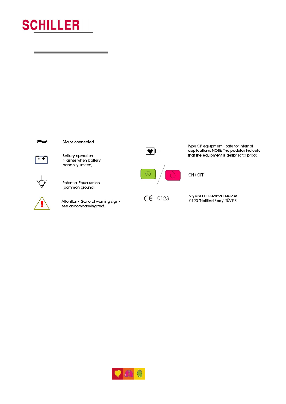
General Symbols
8
Page 9

SCHILLER AT-1 / AT-1smartprint ECG Unit
SERVICE HANDBOOK Issue b June 2001
Contents
Associated Documents 2
Where to Obtain Service 3
Warranty 4
Safety Notices 5
What is in this book 7
CHAPTER 1 OPERATING ELEMENTS 11
Introduction 12
Location & Power 13
The Keyboard 14
AT-1/AT-1smartprint Short Form Operating Instructions 15
Manual ECG Recording (internal printer only) 1 5
System Configuration 1 5
Automatic ECG Recording
with external printer connected and switched on: 1 5
with external printer NOT connected or switched off: 15
Modes of Operation 16
Automatic Mode 1 6
Manual Mode 1 6
Automatic Mode 17
a. without external printer connected or printer switched off 17
b. with external printer 18
Settings 20
Default Settings 22
Language 23
Filters 24
Baseline Filter 24
Mains Filter 24
Myogram Filter 2 5
Defining Lead Sequence & Printout 2 6
Acoustic QRS Indication 2 7
Time / Date 27
Automatic Mode (ECG) Settings, Internal Printer 28
Average Cycles 2 8
Measurements and Markings (M and C versions only) 2 9
Interpretation (C version only) 29
Automatic Mode (ECG) Settings, External Printer 30
Average Cycles 3 0
Measurements and Markings (M and C versions only) 3 1
Interpretation (C version only) 31
Art.No. 2.540022
9
Page 10

Automatic Mode (ECG) Settings 32
Interpretation Settings (C version only) 32
Selecting Rhythm Leads 33
Service Printout 34
Installing Software Options 35
Care & Maintenance 36
Replacing the Recording Paper in the Internal Printer 37
Thermal Paper Handling 38
CHAPTER 2 FUNCTIONAL OVERVIEW 39
Main Board MK 11-10 42
CHAPTER 3 FAULT DIAGNOSIS 45
Fault Diagnosis Chart 46
General Functional Check Procedures 48
Internal Printer Check 49
CHAPTER 4 MODULE REMOVAL AND REPLACEMENT 51
Warnings and Cautions 54
Physical Overview 55
Opening the Case 56
Top Housing Replacement 57
Physical Overview 58
ECG Interface Board MK 11-2 59
Printer Tray Assembly and Thermal Printer 60
Thermal Printer Removal 61
Control and Power Supply Board MK 11-10 62
Battery Pack 64
Keyboard 66
10
CHAPTER 5 ADJUSTMENTS 67
Introduction 68
Warnings, Cautions and Conditions 69
Test Equipment 70
Battery Charge Voltage 71
ECG Amplifier Reference Voltage 72
CHAPTER 6 SPARE PARTS 75
Ordering Information 76
Spare Parts 77
CHAPTER 7 TECHNICAL DATA 79
Technical Data 80
Index 83
Page 11

SCHILLER AT-1 / AT-1smartprint ECG Unit
SERVICE HANDBOOK Issue b June 2001
Chapter 1
Operating Elements
Art.No. 2.540022
11
Page 12
Introduction
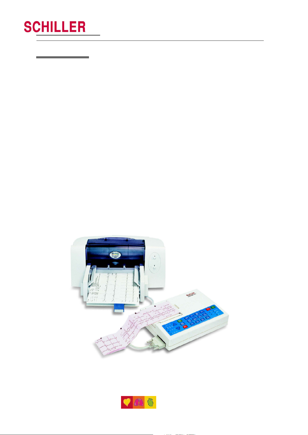
The AT-1 / AT-1 smartprint is a 3-channel ECG recorder with all (12) ECG signals
simultaneously processed to provide instant ECG recordings. Three automatic recording
modes - two for the internal printer and one for the external printer - can be individually
preset to enable one button ECG recording of preferred print formats.
Individual lamps are provided to give power , paper error , filter , lead group and lead off
indications. In addition, any detected disturbance (i.e. loose electrode or end of paper),
gives an audible alarm and the corresponding indicator lamp flashes.
The AT-1 / AT-1 smartprint includes the following features:
• Low weight and compact dimensions
• Printout from integrated quality thermal printer - OR - from external A4 inkjet
printer
• Built-in rechargeable battery for mains-independent use - 2 hrs normal use on one
battery charge
• Simple one key operation for main functions
• Automatic or manual recording modes
• Selectable printing formats - external and internal printer
• Interpretation program option (including measurements) for children and adults
• Choice of 10 languages (AT-1) and 9 languages (AT -1 smartprint) for printing.
12
Page 13
Location & Power
Location
Do not keep or operate the device in a wet, moist, or dusty environment. Also avoid
exposure to direct sunlight or heat from other sources. Do not allow the unit to come
into contact with acidic vapours or liquids, as such contact may cause irreparable
damage. The unit should not be placed near X-ray or diathermy units, large transformers
or motors. The unit must be placed on a flat surface and must not be operated in areas
where there is any danger of explosion.
Power Supply
The mains connection is on the rear of the unit. The mains indicator lamp on the keyboard
is always lit when the unit is connected to the mains supply. The unit can either be
operated from the mains supply or from the built-in rechargeable battery. The power
source is indicated by the respective indicator lamp. When battery capacity is limited,
the battery symbol flashes on and off.
To recharge the battery, connect the device to the mains supply by means of the
supplied power cable. A totally discharged battery needs less than 15 hours to be fully
recharged (60% in less than 3 hours, 90% in less than 7 hours). A fully charged battery
gives approximately 2 hours of normal use. The unit can remain connected to the mains
supply without any danger of damage to either the battery or the unit.
SCHILLER AT-1 / AT-1smartprint ECG Unit
SERVICE HANDBOOK Issue b June 2001
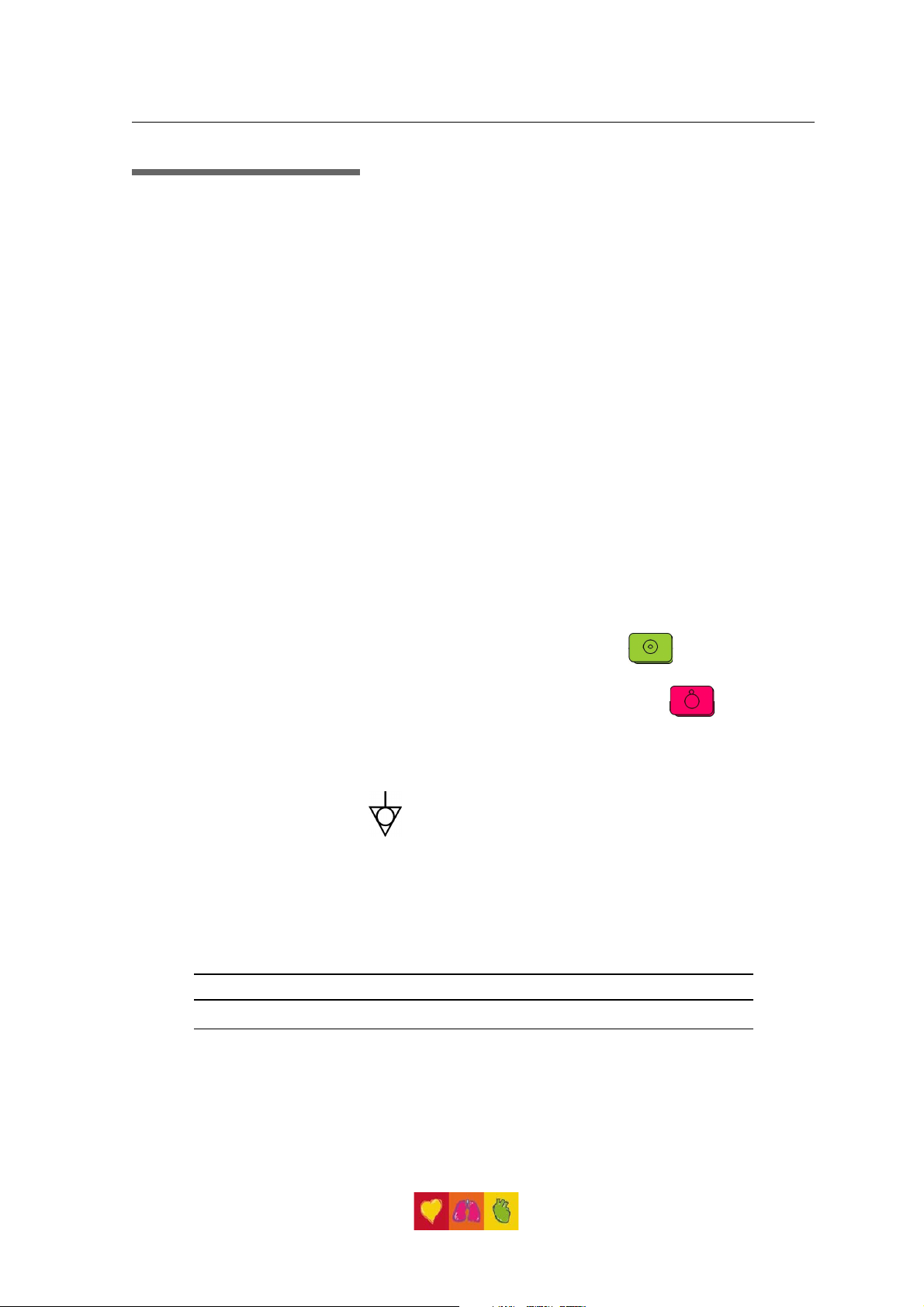
Switching On and Off
The AT-1 / AT-1 smartprint is switched on with the green ON key
and off by means of the red OFF key
The unit is automatically switched off after 5 minutes (30 seconds if battery capacity is
limited) if no key is pressed and the patient cable is not connected.
Potential Equalisation
If the A T-1 / AT-1 smartprint is used in conjunction with other patient connected equipment,
we recommend that the potential equalisation stud on the rear of the unit is connected
to the building common ground with the yellow/green ground cable (Part-no. 2.310005).
When working from an emergency vehicle, the vehicle common ground can be used.
WARNING !
THE UNIT MUST BE GROUNDED WHEN THE EXTERNAL PRINTER IS CONNECTED.
Art.No. 2.540022
13
Page 14

The Keyboard
14
Page 15

SCHILLER AT-1 / AT-1smartprint ECG Unit
SERVICE HANDBOOK Issue b June 2001
AT-1/AT-1smartprint Short Form Operating Instructions
Automatic ECG Recording
with external printer connected and switched on:
Prepare skin, hook up patient.
Switch unit on, press ON
Press AUTO to record and print externally
with external printer NOT connected or switched
off:
To record and print on internal printer:
For AUTO Format 1 press
For Auto Format 2 press
Press COPY for additional copies.
Manual ECG Recording (internal printer only)
Prepare skin, hook up patient.
Switch unit on, press ON
Press MAN START
Change lead group with
Press STOP to stop the printout.
Electrode hook-up check
and then
Art.No. 2.540022
Press
electrode dc offsets.
Best results are obtained when the electrode voltage
readings (right column) are between +50mV and - 50mV .
Filter On/Off
Press
System Configuration
Press
settings.
to switch the (Myogram) filter On / Off.
for print-out of
to print system
15
Page 16

Modes of Operation
Automatic Mode
a. without external printer connected or printer switched off
Automatic Mode provides a printout giving 10 seconds of ECG recording of all 12 leads
with a choice of 2 different formats (only for S version).
The following can be programmed freely for each of the 2 formats before recording:
• Lead Format
• Chart Speed
• With the optional interpretation program installed it is also possible to select the
measurement table, average cycles with optional markings and interpretation
statements for the printout.
For further information see paragraph `Automatic Mode (ECG) Settings` on page 28.
b. with external printer connected and switched on
Only one Automatic Mode format possible. Other details as above.
For further information see paragraph `Automatic Mode (ECG) Settings` on page 30.
Manual Mode
Manual Mode provides a real time print-out of 3 selected leads and is only possible on
the internal thermal printer.
The following can be freely selected before or during recording:
• Lead Group
• Chart Speed
• Sensitivity
• Myogram Filter
For further information see paragraph `Manual Mode` on page 19.
16
Page 17

Automatic Mode
a. without external printer connected or printer switched off
In automa tic m ode, a full 12-lead ECG is printed in one of two predefined formats
with selectable sensitivity. These formats (see Settings) are selected by the user to suit
his specific needs and requirements.
SCHILLER AT-1 / AT-1smartprint ECG Unit
SERVICE HANDBOOK Issue b June 2001
When the AUTO GAIN key
unit detects very large waveform amplitudes and sets the sensitivity for the extremity
and/or precordial leads accordingly to reduce the overlapping of traces.
To start the automatic ECG recording in Format 1, press the AUTO START
key:
To start the automatic recording in Format 2, press the ALT key followed by
the AUTO START key:
Depending upon which option is included, the printout gives the following:
• ECG recording of all leads in either Standard or Cabrera format according to
selection
• Sensitivity
• Heart Rate
• Speed
• Filter Settings
• Interpretation statements (with option C)
• Average Cycles (with options M, C)
• Intervals (with options M, C)
• Axes (with options M, C)
• Detailed Measurement Table (with options M, C)
To obtain an extra printout of the ECG recording in Format 1, simply press the COPY key:
is pressed before recording in automatic mode, the
+
To obtain an extra printout of the second format, press the ALT key followed by the
COPY key:
Note: The Auto mode settings for the two formats are detailed in the paragraph
Art.No. 2.540022
-
entitled ' Automatic Mode (ECG) Settings` later in this chapter .
17
Page 18

Automatic Mode
b. with external printer
With the external printer connected and switched on, only one Auto Mode format
(selectable) is available.
To start the automatic ECG recording in Automatic Mode, press the AUTO
START key:
For further information see paragraph `Automatic Mode (ECG) Settings` on page 30.
18
Page 19
Manual Mode
Manual mode provides a real-time ECG printout of 3 selected leads with full control
of parameter selection. This is only possible on the internal thermal printer.
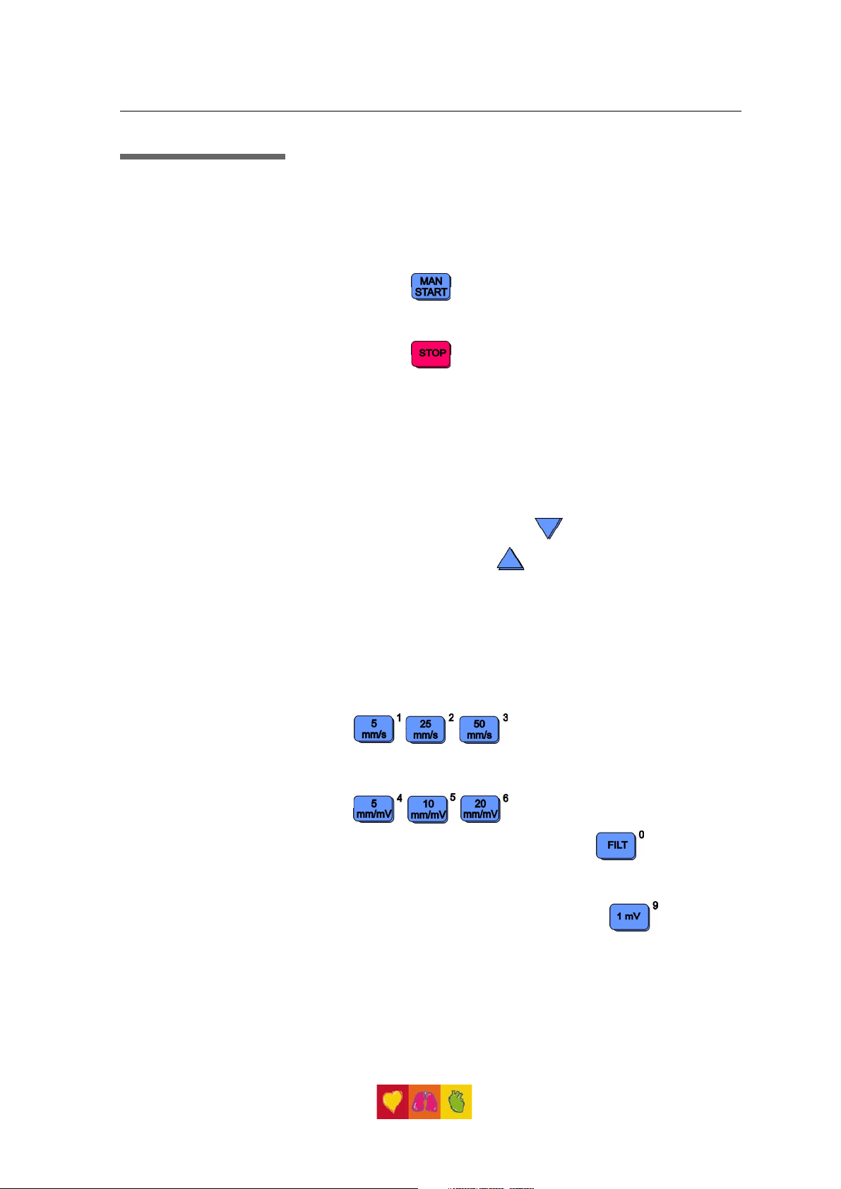
To start the manual recording of a real-time ECG, press the MAN START
Printout key
To stop the manual recording (printout) press the STOP key
The printout provides you with the following:
• Three (selected) leads with lead identification.
• On the lower edge, the chart speed and filter settings (if on).
• At the top, the heart rate as current average of 4 beats, trace sensitivity.
SCHILLER AT-1 / AT-1smartprint ECG Unit
SERVICE HANDBOOK Issue b June 2001
The following can be freely chosen during or before the recording:
Lead Group by means of the LEAD FORWARD
and LEAD BACKWARD key
The following lead groups are selectable:
• I, II, III aVR, aVL, aVF
(Cabrera: aVL, I, -aVR / II, aVF, III)
• V1, V2, V3 / V4, V5, V6
Chart Speed Select speed 5, 25 or 50 mm/s by means of the SPEED keys:
Sensitivity Select 5, 10 or 20 mm/mV by means of the SENSITIVITY keys:
Myogram Filter Switch the filter ON or OFF with the FILTER key:
25 Hz or 35 Hz is displayed on the bottom line of the printout
when the filter is switched on.
Recentering T o re-centr e the ECG traces, press the 1mV key
Art.No. 2.540022
19
Page 20

Settings
Each parameter is set by means of a code. This code comprises a combination of keys
starting with the ALT key followed by two or three numbers. The setting is confirmed with
the ST OP key. As soon as the ALT key is pressed, the keyboard is dedicated to the
programming function.
Note: The Alternative (ALT) function is only active for 4 seconds. If a programming
The setting is remembered and the keyboard released for other functions when the
STOP key is pressed. Once a setting has been confirmed, it is stored in the memory
even when the unit is switched off.
Example
If you want to set the language on your ECG unit to English, the key sequence given in
the table (see page 23), is
key is not pressed within 4 seconds, the unit reverts to standard mode. The
ALT key must again be pressed to activate the programming mode
ALT - 0 - 2 - 2 - STOP.
20
On the following pages the programmable parameters and the programming sequences
are described in detail.
Page 21

Settings (cont.)
The defined formats and settings for your unit can be checked as follows:
A printout of the defined settings will be produced and gives the following information,
depending on the installed software.
SCHILLER AT-1 / AT-1smartprint ECG Unit
SERVICE HANDBOOK Issue b June 2001
ALT - 0 - 1 - any number
Unit designation Software version, Software option installed (C =
Interpretation) and interpretation version
Serial number Serial number of the unit
Leads Standard (S) or Cabrera (C)
ECG Format Long (ooo), Short (o) or Suppressed (-)
M ECG Average cycles as defined in auto ECG recording setup
(e.g. 4 * 3 (25 mm/s) + 2)
Measurements Enabled (+) or Suppressed (-)
Marks E n a b l e d (+ ) o r Su ppressed (-)
Interpretation Enabled (+) or Suppressed (-)
Selected Rhythm leads Leads selected for R1 and R2
Automatic Centering Enabled (+) or Suppressed (-)
Paper type Z-folded
Pr intout of signal s Sequential or Simultaneous
Baseline Filter 0. 0 5 , 0 . 1 5 o r 0 .3 0 H z
Mains Filter 50, 6 0 Hz o r OFF ( -)
Myogram Filter 25 or 35 H z, O N (+ ) or OFF (-)
Interpretation settings: N/A: + /- ‘no rmal/a bno rma l’ i s wr itten (+) or
suppressed (-)
U:+/- ‘unconfirmed report’ is written (+) or
suppressed (-)
A30:+/- patient age is assumed to be < 30 (-)
or >30 (+)
S: +/- low (-) or high (+) sensitivity
Art.No. 2.540022
21
Page 22
Settings (cont.)
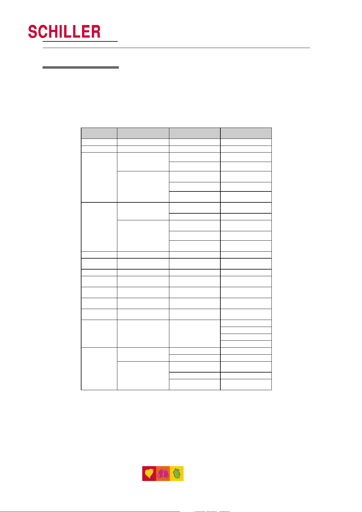
Default Settings
To reset the unit to the basic default settings, proceed as follows:
ALT - 0 - 6 - 6
SETTINGS S = STANDARD M = MEASUREMENTS
LANGUAGE AS SET AS SET AS SET
LEADS STANDARD (S) STANDARD (S) STANDARD (S)
ECG: 25MM/S, SHORT (O)
AUTO FORMAT 1
PATIENT DATA FORM
ENABLED +
ECG: 25MM/S, LONG (OOO)
AUTO FORMAT 2
PATIENT DATA FORM
ENABLED +
RHYTHM LEADS V1, II V1, II
AUTOM.
CENTERING
PAPER Z - FOLD Z - FOLD Z - FOLD
PRINTOUT OF
SIGNALS
BASELINE FILTER
SETTING
MAINS FILTER
SETTINGS
MYOGRAM
FILTER SETTING
INTERPRETATION
SETTINGS
EXTERNAL
PRINTER
ENABLED (+) ENABLED (+) ENABLED (+)
SEQUENTIAL SEQUENTIAL SEQUENTIAL
0.05HZ 0.05HZ 0.05HZ
50HZ (60HZ) 50HZ (60HZ) 50HZ (60HZ)
35HZ, OFF (-) 35HZ, OFF (-) 35HZ, OFF (-)
ECG: 25MM/S, SHORT (O)
PATIENT DATA FORM
ENABLED +
ECG : 25MM/S, SHORT (O) ECG : 25MM/S, SHORT (O)
M ECG :6*2 (50MM/S + 1) M ECG: 6*2 (50MM/S + 1)
MEASUREMENTS:
SUPRESSED (-)
MARKS: ENABLED (+) MARKS: ENABLED (+)
ECG : 25MM/S, LONG
(OOO)
M ECG: - - M ECG: NONE
MEASUREMENTS:
SUPRESSED (-)
MARKS: ENABLED (+) MARKS: ENABLED (+)
ECG : 25MM/S, SHORT (O) ECG : 25MM/S, SHORT (O)
M ECG: 6*2 (50MM/S) + 2 M ECG: 6*2 (50MM/S) + 2
MEASUREMENTS:
SUPRESSED (-)
MARKS: ENABLED (+) MARKS: ENABLED (+)
C = WITH
INTERPRETATION
MEASUREMENTS:
SUPRESSED (-)
INTERPRETATION:
ENABLED (+)
ECG : 25MM/S, LONG
(OOO)
MEASUREMENTS:
SUPRESSED (-)
INTERPRETATION:
DISABLED (-)
N/A: SUPRESSED (-)
U: ENABLED (+)
A30: UNDER THIRTY (- )
S: LOW (-)
MEASUREMENTS:
SUPRESSED (-)
INTERPRETATION:
ENABLED (+)
22
Page 23

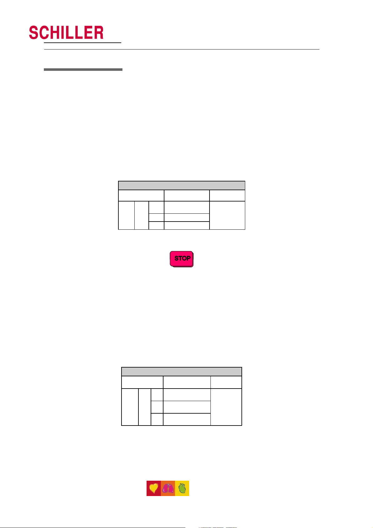
Settings (cont.)
Language
The language is selected as follows:
SCHILLER AT-1 / AT-1smartprint ECG Unit
SERVICE HANDBOOK Issue b June 2001
Language Selection AT-1
Entry Key Sequence Language Confirm
1 German
2 English
3 French
4 Swedish
ALT 0 2
5 American
6 Italian
7 Spanish
8 Portugese
9 Dutch
0 Russian
STOP key
Press
Language S election AT-1 smartprint
Entry Key Sequence Language Confirm
1 German
2 English
3 French
4 Swedish
ALT 0 2
5 American
6 Italian
7 Spanish
8 Portugese
9 Dutch
Confirm the selection by pressing
Notes: The difference between English and American is the mains filter setting -
English = 50Hz; American = 60Hz and the physical units.
Press
STOP key
Art.No. 2.540022
23
Page 24
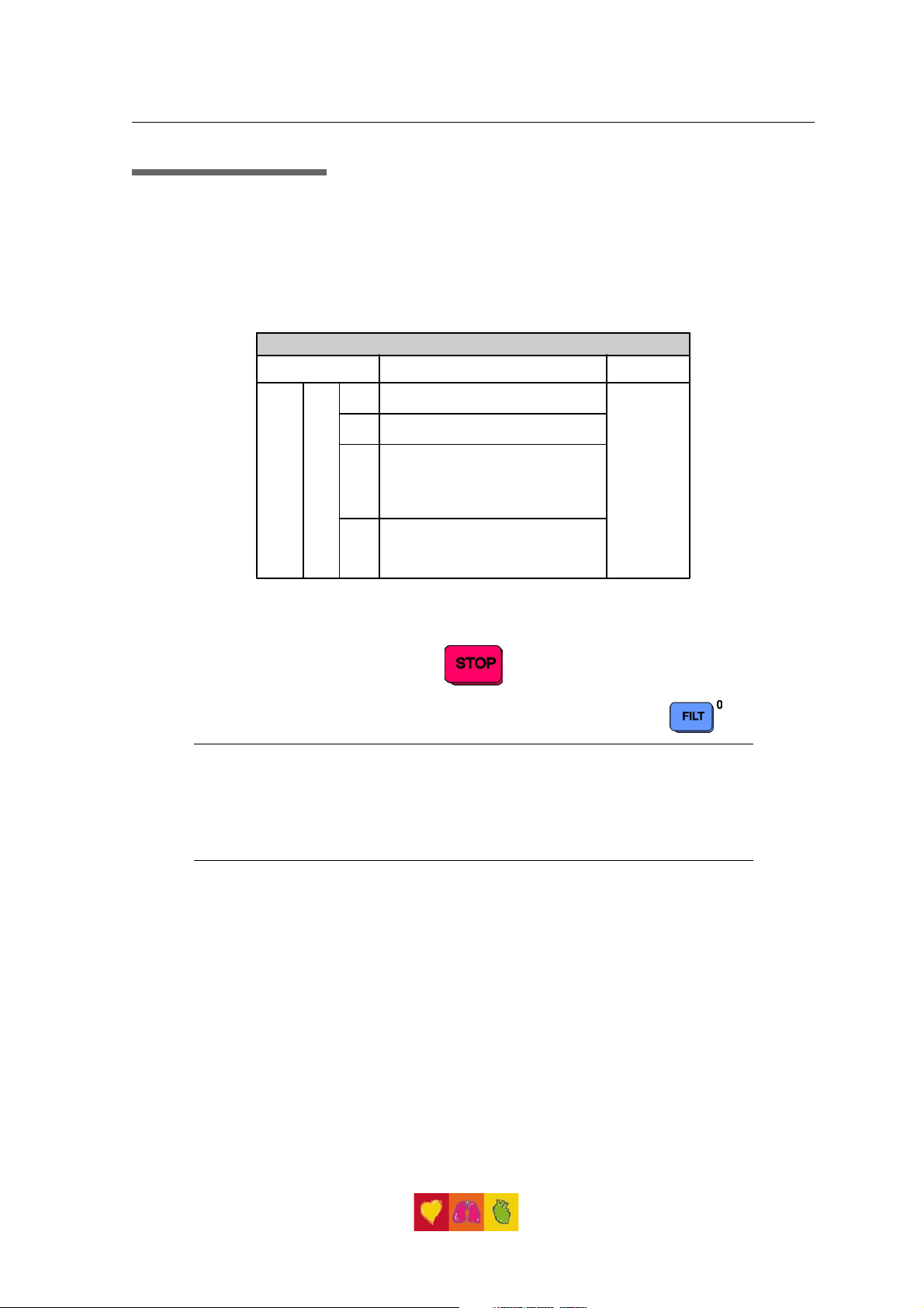
Settings (cont.)
Filters
There are three different filters which can be set individually as follows:
• Baseline filter
• Mains filter
• Myogram filter
Baseline Filter
The digital Baselin e fi lte r suppresses excessive baseline drifts. The setting options are
as follows:
Baseline Filter
Entry Key Sequence Filter Setting Confirm
ALT 5
0 0.05 H z (default)
1 0.15 Hz
3 0.30 Hz
Press STOP
key
Confirm the selection by pressing
Note: The set value is the lower limit of the frequency range and is normally set to
0.05 Hz. The settings 0.15 and 0.30 Hz should only be used when absolutely
necessary , as the possibility exists that they could affect the original ECG
signal, especially the ST segments.
Mains Filter
The Mains filter is an adaptive digital interference filter designed to suppress AC
interference without attenuating or distorting the ECG.
Set the mains filter in accordance with the frequency of your local mains supply as
follows:
Mains Filter
Entry Key
Sequence
ALT 8
Filter Setting Confirm
5 Mains Filter 50 Hz
6 Mains Filter 60 Hz
9 Mains Filter Off
Press STOP
key
24
Page 25
Settings (cont.)
Myogram Filter
The Myogram filter suppresses disturbances caused by strong muscle tremor. The set
value will be the new upper limit of the frequency range as soon as the FILT ER key is
pressed on or programmed as default when the unit is switched on. When the Myogram
filter is on, the value, i.e. 35 Hz is displayed on the bottom line of the printout.
Entry Key Sequence Setting Confirm
SCHILLER AT-1 / AT-1smartprint ECG Unit
SERVICE HANDBOOK Issue b June 2001
Myogram Filter
2 Myogram Filter 25 Hz
3 Myogram Filter 35 Hz
ALT 8
Myogram Filter active when the unit is first
1
switched on (marked on printout with +)
Myogram Filter off when the unit is first
8
switched on (marked on printout with - )
Press STOP
key
Confirm the selection by pressing the STO P key
The myogram filter is switched on and off manually with the FILTE R KEY
Note: An ECG recorded in auto mode is stored unfiltered. It is therefore possible to
print the stored ECG either with or without passing the myogram filter. Filter
ON is indicated in the bottom information line of the printout. When theFILTER
key is pressed again, the filter is switched off and the `35 Hz` indication on
the bottom information line of the printout is removed. The cutoff frequency
of the myogram filter is set to either 25 or 35 Hz.
Art.No. 2.540022
25
Page 26
Settings (cont.)
Defining Lead Sequence & Printout
The required settings can be selected as follows:
Sequences, Print & Auto-centering
Entry Key Sequence Definition Confirm
1 Standard Lead Sequence
2 Cabrera Lead Sequence
3 Simultaneous Print
ALT 7
Confirm the selection by pressing the STOP key
4 Se quential Print
5 Auto-centering ON
6 Auto-centering OFF
7 Z-fold paper
Press STOP
key
The selectable printout forms are:
Simultaneous All ECG le ads are printed in the same time segment ( in
automatic mode only).
Sequential Each group is a contiguous time segment of approximately
2.5 or 5 seconds (in automatic mode only).
Auto-Centering ON All ECG traces are centred dynamically for optimal use of
paper width.
Auto-Centering OFF ECG traces are set to a fixed baseline position and may
possibly overlap.
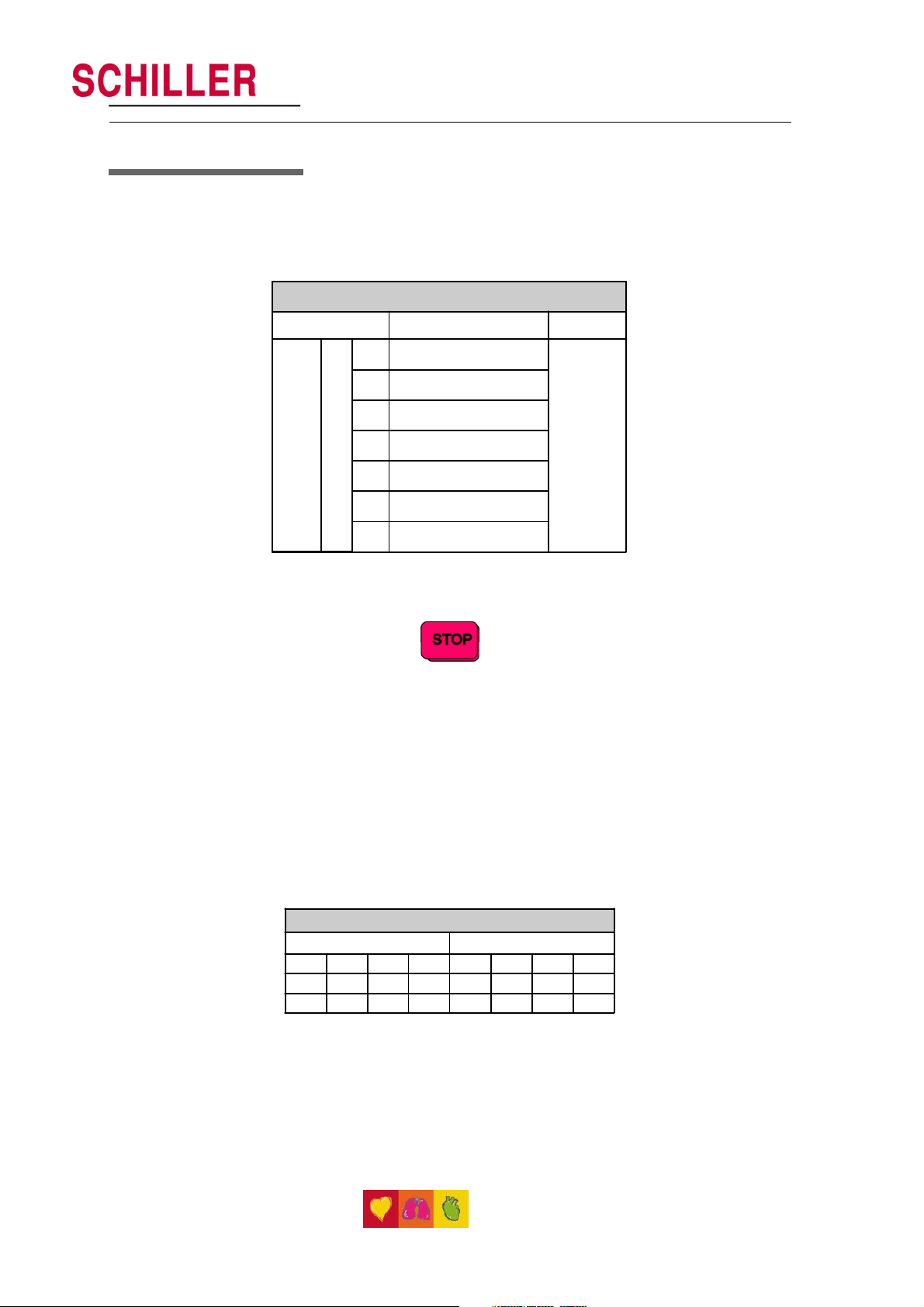
The Standard and Cabrera lead groups available for the AT-1 / AT-1smartprint are:
Lea d Groups
Standard Cabrera
I aVR V1 V4 aVL II V1 V4
II aVL V2 V5 I aVF V2 V5
III aVF V3 V6 -aVR III V3 V6
26
Page 27

Settings (cont.)
Acoustic QRS Indication
The acoustic QRS beep can be switched on or off at any time by pressing the QRS BEEP
key.
Time / Date (AT-1 smartprint only)
The required settings can be selected as follows:
Time
ALT 0 5 1 HHMMSS beep
Date
ALT 0 5 2 DDMMYY beep
SCHILLER AT-1 / AT-1smartprint ECG Unit
SERVICE HANDBOOK Issue b June 2001
Setting the Time and Date
Key Sequence Enter Data Confirmation
Seasonal Time Variation
Time change Key Sequence
Wintertime to
Summertime (+1Hr)
Summertime to
Wintertime (- 1 Hr)
ALT 0 5 4
ALT 0 5 5
Note: If the battery has been disconnected for more than half an hour, the clock
oscillator must be restarted before setting the time. To do this the following
key sequence must be pressed:
ALT - 0 - 5 - 9
This will start the oscillator and the time can be set.
Note: The time and date only appear on the AUTO printout from the external printer .
Art.No. 2.540022
27
Page 28

Automatic Mode (ECG) Settings, Internal Printer
Two separate Auto formats can be defined for the internal printer in the AT-1 /
AT -1smartprint. When defining auto format 1 the key sequence
ALT - 1
precedes the setting. When defining auto format 2 the key sequence
ALT - 2
precedes the setting.
The automatic mode formats are detailed on the following pages. The ECG format is set
as follows:
ECG Format Internal Printer
Entry Key Sequence Printout Confirm
5 No leads printed
6 Leads are printed in short form (3 sheets)
ALT 1 or 2 1
7 Leads are printed in long form (6 sheets)
8 Chart Speed 25mm/s
9 Chart Speed 50mm/s
Average Cycles
The Average cycles are defined as follows:
Note: Lead selection for the rhythm lead(s) is defined on page 33.
Average Cycles (interpretation option only) Inte rnal printe r
Entry Key Sequence Printout Confirm
5 No average lead cycles are printed
6
7
ALT 1 or 2 2
4 x 3 (25 mm/s). The average
complexes are printed in 4 groups of
three leads at a chart speed of 25mm/s
4 x 3 (50 mm/s). The average
complexes are printed in 4 groups of
three leads at a chart speed of 50mm/s
Press STOP key
Press STOP
key
28
6 x 2 (50 mm/s) + 1 rhythm lead
(25mm/s). The average complexes are
8
printed in 6 groups of two leads at a
chart speed of 50mm/s
12 x 1 (25 mm/s) + 2 rhythm leads
(25mm/s). The average complexes are
9
printed out for all 12 leads at a chart
speed of 50mm/s
Page 29

SCHILLER AT-1 / AT-1smartprint ECG Unit
SERVICE HANDBOOK Issue b June 2001
Automatic Mode (ECG) Settings, Internal Printer (cont.)
Measurements and Markings (M and C versions only)
To define the measurements and markings proceed as follows:
Measurements (M and C Options Only) Internal printer
Entry Key Sequence Printout Confirm
Detailed table of measurement results
omitted - however, the values of electrical
5
ALT 1 or 2 3
axes, intervals, and heart rate are not
Detailed table of measurement results is
6
7 Referenece markings are omitted
Reference markings (beginning and end of
8
P wave and QRS, and end of T wave)
are added to the ECG average cycles
suppressed.
printed
Press STOP
key
Interpretation (C version only)
To print or suppress interpretation statements on the printout proceed as follows:
Interpretation (Inte rpre tation Option Only) Internal printe r
Entry Key Sequence Printout Confirm
ALT 1 or 2 4
5 Interpretation is omitted
6 Interpretation is printed
Confirm the selection by pressing the STOP key
Full details of the interpretation option are given in the SCHILLER ECG Measurement and
Interpretation booklet (art. No. 2.510 179).
Press STOP
key
Art.No. 2.540022
29
Page 30

Automatic Mode (ECG) Settings, External Printer
One Auto format can be defined for the external printer in the AT-1smartprint. When
defining the auto format the key sequence
ALT - 9
precedes the setting.
The automatic mode format is detailed on the following pages. The ECG format is set as
follows:
ECG Format External printe r
Entry Key Sequence Printout Confirm
1 1 page A4 with 12 leads at 25mm/s (1x12)
One page with the first 8 leads printed for 5s and the last 4
2
5 No leads printed
6 1 page A4 with 12 leads printed in short form (2x6)
leads printed for 10s
ALT 9 1
7 2 pages A4 each with 6 leads printed in long form (6 + 6)
8 Chart Speed 25mm/s
9 Chart Speed 50mm/s
1 page A4 with 4 groups of 3 leads (4x3) at 25mm/s
0
+ 1 rhythm (25mm/s)
Average Cycles
The Average cycles are defined as follows:
Note: Lead selection for the rhythm lead(s) is defined on page 33
Average Cycles (interpretation option only) External printer
Entry Key Sequence Printout Confirm
5 No average lead cycles are printed
4 x 3 (25 mm/s) + 2 rhythm leads
(25mm/s). The average complexes are
6
printed in 4 groups of three leads at a
chart speed of 25mm/s
4 x 3 (50 mm/s) + 2 rhythm leads
(25mm/s). The average complexes are
ALT 9 2
7
printed in 4 groups of three leads at a
chart speed of 50mm/s
Press STOP key
Press STOP
key
30
6 x 2 (50 mm/s) + 2 rhythm leads
(25mm/s). The average complexes are
8
pr inted in 6 groups of two leads at a
chart speed of 50mm/s
12 x 1 lead (25mm/s) + 2 rhythm leads
9
(25mm/s)
Page 31

SCHILLER AT-1 / AT-1smartprint ECG Unit
SERVICE HANDBOOK Issue b June 2001
Automatic Mode (ECG) Settings, External Printer
(cont.)
Measurements and Markings (M and C versions only)
To define the measurements and markings proceed as follows:
Measurements (M and C Options Only) External printer
Entry Key Sequence Printout Confirm
Detailed table of measurement results
omitted - however, the values of electrical
5
ALT 9 3
axes, intervals, and heart rate are not
Detailed table of measurement results is
6
7 Reference markings are omitted
Reference markings (beginning and end of
8
P wave and QRS, and end of T wave)
are added to the ECG average cycles
suppressed.
printed
Press STOP
key
Interpretation (C version only)
To print or suppress interpretation statements on the printout proceed as follows:
Interpretation (Inte rpre tation Option Only) External printer
Entry Key Sequence Printout Confirm
ALT 9 4
5 Interpretation is omitted
6 Interpretation is printed
Confirm the selection by pressing the STOP key
Full details of the interpretation option are given in the SCHILLER ECG Measurement
and Interpretation booklet (art. No. 2.510 179).
Press STOP
key
Art.No. 2.540022
31
Page 32

Automatic Mode (ECG) Settings
Interpretation Settings (C version only)
The interpretation settings enable the user to determine whether or not certain comments
will be added to the interpretation statements on the ECG printout. Furthermore, the
patient’s age can be defined (<30 or >30) and if low or high sensitivity should be
applied. Low sensitivity will suppress certain non-specific and less important ECG diagnosis;
this may be advisable when carrying out ECGs for screening.
Interpretation Settings
Entry Key
Sequence
ALT 6
"Normal" / "Abnormal" is not
1
2 "Normal" / "Abnormal" is printed
3 "Unconfirmed report" is not printed
4 "Unconfirmed report" is printed
5 Patient age assumed to be < 30
6 Patient age assumed to be > 30
7 Low sensitivity
8 High sensitivity
Setting Confirm
printed
Press STOP
key
32
Page 33

SCHILLER AT-1 / AT-1smartprint ECG Unit
SERVICE HANDBOOK Issue b June 2001
Automatic Mode (ECG) Settings (cont.)
Selecting Rhythm Leads
The rhythm leads are printed out as defined. Two separate rhythm leads can be selected.
The following formats can be set:
Rhythm Lea ds (interpretation option only)
Entry Key
Sequence
3 De fine rhythm lead one
ALT
4 Define rhythm lead two
The 2 rhythm leads are defined as follows:
Entry Key Sequence Lead Confirm
ALT 3 or 4 8
Setup Format
Extremity Leads
1I
2II
3 III
4 aVR
5 aVL
6 aVF
Press
STOP key
Precordial Leads
Entry Key Sequence Lead Confirm
1V1
2V2
ALT 3 or 4 9
3V3
4V4
5V5
6V6
Confirm the selection by pressing the STOP key
Press
STOP key
Art.No. 2.540022
33
Page 34

Service Printout
The service printout provides information about the patient cable and electrodes and
gives the values of certain reference voltages and important internal offset values.
These values are for information only . To obtain the service printout press
ECG Reference Voltage Th is provi des me asureme nts and setting facilities for the
• Uref + This gives the value of the reference voltage used in the
• Uref - This is a negative reference voltage used on the ECG Amplifier
• Udif This is the sum of the two reference values above (Uref+and
• Uoff This is the value of the offset voltage on the multiplexer circuit.
• Calib This value is the Udif value divided by 4. The nominal value is
Electrode dc offset This gives the voltage drop in the patient cable and can
TPH TEMP This is the measured ambient temperature that the processor
EPROM This is the checksum for the EPROM. Its value varies from one
ALT - 0 - 3 - 3
reference voltage used for accurate measurement of ECG
signals
multiplexer circuit on the ECG Amplifier. The value of the
reference voltage is 2000 mV ±20 mV.
board. The value of this voltage should be -2000 mV ±20 mV.
Uref-). This value must be 4000 mV ± 20 mV.
This value should be between +150mV and - 150mV .
1000 ±5 mV .
indicate any faults in the patient cable or patient electrode.
The value given is the dc voltage between the left leg electrode
and all other electrodes. The measurements obtained will
indicate any cable short circuits or open circuits. The measured
voltage value will depend on where the electrodes are
connected. The voltage readings that can be expected are
as follows:
• With patient connected: ± 100mV
• With patient simulator connected: ± 20 mV. This will
depend on the patient simulator used and must be taken
as a flexible measurement.
• With all electrodes shorted together: ± 20 mV
• No patient cable connected: -350 to -450mV
uses to correct print quality.
This reading should be ambient temperature ± 5
software version to another.
o
.
34
Page 35

Installing Software Options
To upgrade the AT-1 / AT-1 smartprint, for example from standard to M version, type the
following:
ALT - 0 - 4 - followed by the upgrade code (obtainable from SCHILLER).
Acceptance of the code is indicated by a series of beeps.
CAUTION
MORE THAN 10 UNSUCCESSFUL ATTEMPTS TO ENTER THE CODE BLOCKS THE UNIT.
SCHILLER AT-1 / AT-1smartprint ECG Unit
SERVICE HANDBOOK Issue b June 2001
Art.No. 2.540022
35
Page 36

Care & Maintenance
12 Monthly Check
The unit should undergo a technical safety check every 12 months. This safety check
should include the following:
• Visual inspection of the unit and cables.
• Electrical safety tests according to IEC 601-1 Clause 19.
• Functional tests according to Chapter 3.
The test results must be documented.
Cleaning the Casing
SWITCH THE UNIT OFF BEFORE CLEANING AND DISCONNECT THE MAINS AND
THE EXTERNAL PRINTER (IF PRESENT). DO NOT, UNDER ANY CIRCUMSTANCES,
IMMERSE THE APPARATUS INTO A CLEANING LIQUID OR STERILIZE WITH HOT
WATER, STEAM, OR AIR.
The casing of the AT-1 / AT-1smartprint can be cleaned with a soft damp cloth on the
surface only . Where necessary a domestic non-caustic cleaner can be used for grease
and finger marks.
CAUTION
Patient Cable
CAUTION
ALIGN THE LEADS IN SUCH A WAY AS TO PREVENT ANYONE STUMBLING OVER THEM OR
ANY DAMAGE CAUSED BY THE WHEELS OF INSTRUMENT TROLLEYS. THE SAME CAUTION APPLIES
TO THE STORAGE OF THE LEADS.
The patient cable should not be exposed to excessive mechanical stress. Whenever
disconnecting the leads, hold the plugs and not the cables.
The cable can be wiped with soapy water . Sterilization, if required, should be done with
gas only and not with steam. To disinfect, wipe the cable with hospital standard
disinfectant.
Cleaning the Thermal Printhead of the internal printer
If the printer is used a lot, a residue of printers ink (from the grid on the paper) can build
up on the printhead. This can cause the print quality to deteriorate. We recommend
therefore that every month the printhead is cleaned with alcohol as follows:
Remove the paper tray. The thermal printhead is found under the paper tray release
catch. With a tissue dampened in alcohol, gently rub the printhead to remove the ink
residue. If the printhead is badly soiled, the colour of the paper grid ink (i.e. red or
green) will show on the tissue.
36
Page 37

SCHILLER AT-1 / AT-1smartprint ECG Unit
SERVICE HANDBOOK Issue b June 2001
Replacing the Recording Paper in the Internal
Printer
The recording paper must be replaced as soon as the end of the paper is indicated by
a red stripe on the lower edge. After the indication first appears, there are about 8
pages left. However, we recommend that the paper be replaced immediately. If no
paper is left, the printing process is interrupted and the paper warning lamp starts to
blink. To replace the paper proceed as follows:
• Press the latch for the paper tray to release the lid with the rubber roller.
• Remove any remaining paper from the paper tray .
• Place a new paper pack into the paper tray with the printed (grid) side facing
• Close the lid and press firmly until release catches. Press the STOP key
SCHILLER can only guarantee perfect printouts when SCHILLER original chart paper or
chart paper of the same quality is used.
Art.No. 2.540022
upwards.
to transport the paper to the start position.
37
Page 38

Thermal Paper Handling
The thermal paper used in the AT-1 / AT-1smartprint requires slightly different handling to
normal paper as it can react with chemicals and to heat. However , when the following
points are remembered, the paper will give reliable results:
The following points apply to both storage and when archiving the results.
1. Before use, keep the paper in its original cardboard cover . Do not remove the
cardboard cover until the paper is to be used.
2. Store in a cool, dark and dry area.
3. Do not store near chemicals e.g. sterilisation liquids.
4. In particular do not store in a plastic cover.
5. Certain glues can react with the paper - do not attach the printout onto a
mounting sheet with glue.
38
Page 39

SCHILLER AT-1 / AT-1smartprint ECG Unit
SERVICE HANDBOOK Issue b June 2001
Chapter 2
Functional Overview
Art.No. 2.540022
39
Page 40

printer
External Inkjet
TOP CASING
Batt. LED,
Filter, Elec-
Lead LEDs,
trode loose
Keyboard
detector
Paper mark
PRINTER
ASSEMBLY
head
Thermal print
Printer motor
12 V
Battery
+5V ref
Voltage
regulator
ON / OFF
MAIN BOARD MK 11-10
TP 12 & TP 13
SI2
+5.2V
Voltage
SI3
+US
control
regulator
Switching
P2
+24V
voltage reg.
P3 (part)
controller
External printer
conversion
Voltage sense &
MON
Motor running
Keyboard
LED Decoder /
BLOW
10.3V MON
interface
P3
+5Vi
Power rail
-5Vi
-10Vi
stabilisation
P1
Print head
System
2Vi
+
reference
DC - DC
converter
controller
Software
EPROM
P5
voltage
P4
Stepper motor
Timer
CPU /
decoder /
CTRL
MUX
Signal multi-
plexer (PWM)
P6
controller
40
LED
Mains
P3 (part)
Voltage sensing
circuit
+US
Battery charger &
+Batt
SI1
Mains
voltage regulator
OFF from CPU
ON from keyboard
+U
Overvoltage
Rectification
+5.2V
tor
connec-
protection
+24V
protection
Undervoltage
+US
PATIENT ISOLATION (4kVrms)
AC - DC
converter
400 kHz
DC - AC
converter
MK 11-2
ECG INTERFACE
+5Vi
+5.2Vi
and filter
Input amplifier
P1
Patient
connector
Page 41

Introduction
This chapter provides a functional overview of the AT-1 / AT-1smartprint electronics. The
aim of this overview is to enable the service engineer to identify processing paths in
order to help identify possible faulty modules. A functional block diagram supports the
text.
SCHILLER AT-1 / AT-1smartprint ECG Unit
SERVICE HANDBOOK Issue b June 2001
Art.No. 2.540022
41
Page 42

Main Board MK 11-10
Power Supply
The mains supply is full wave rectified to produce an unregulated dc supply of
approximately 35 V (+U). This voltage is used by a switched voltage generator to produce
+UD (13.5V). +UD charges the battery when mains is connected. When mains is not
connected, +UD is the battery voltage.
An ON/OFF control logic switches +UD to three voltage regulators. The unit is switched
on directly from the keyboard and then held on from the CPU. Detection of overvoltage
on either the 5.2 V or 24 V supplies directly switches the unit off. Similarly when an
undervoltage is detected on +US (indicating overcurrent) the unit is directly switched
off.
The mains LED is lit directly when mains is connected. The same circuit also monitors the
switched dc supply (+US) and activates signal +BATT when the unit is switched on and
mains is not connected (i.e. the unit is running on battery power).
A Battery low signal (BLOW) is set to logic 0 when battery voltage (+US) falls to 11.3 V. A
circuit compensates for voltage drop when the printer stepper motor is active and the
BLOW signal is active only at 10.3 V.
Note : The battery voltage is also monitored directly by the CPU which switches the
unit off when the voltage falls below approximately 9.4 V.
CPU and processing circuits
Overall control and coordination of the AT-1 / AT-1smartprint is performed by a Motorola
68332 Microcontroller , which performs all timing and control functions.
Memory
• An EPROM with 128 kByte memory contains the unit software.
• A static RAM memory stores the ECG data and comprises two 256 kByte RAM
chips.
• A serial EEPROM (U48) stores the unit base settings.
Thermal Printhead Controller
The thermal printhead is controlled by a printhead controller and a CPU timer circuit.
The printhead controller serialises the data for the printhead and the timer circuit controls
how long current is applied to the head, and thus the intensity of the printout.
Printer Timing
Strobe generation is controlled by the CPU when one complete pixel line of data is
ready to be written. Pulse length of STRB1 and STRB2 (each of which controls half of the
pixel array) depends on the TPH temperature and therefore on the pulse width of the
TPHT signal.
Note: TPH temperature reading is described on page 34.
42
Page 43

Main Board MK 11-10 (cont.)
Paper Mark
The pulsed paper mark signal from the printer is fed to a comparator . A detected paper
mark supresses any (logic 0) pulses of PMARK at the output of comparator U38.
Power On Reset
The Power on reset circuit controls the master reset of the CPU. This circuit has two
functions as follows:
• To provide a delay on initial switch-on to ensure that the power supply is fully
stabilized and give the 200ms reset time required by the 68332 processor .
• To disable the unit if the +5V rail drops below +4.75V.
Stepper Motor Controller
The printer stepper motor controller sets the speed of the printer motor with a clock
frequency dictated by the master CPU.
The purpose of the stepper motor controller circuit is to ensure that the motor speed
requested by the microprocessor is achieved and maintained.
SCHILLER AT-1 / AT-1smartprint ECG Unit
SERVICE HANDBOOK Issue b June 2001
ECG Isolated Power Supplies
DC/DC converter circuits produce all the isolated power voltages required by the ECG
Amplifier circuit.
The -2.0Vi and the 2Vi isolated reference voltages are generated from the -5Vi supply .
Note: When taking measurements always ensure that the isolated ground is used
for reference.
ECG Signal
The incoming ECG signals RA, LA, and C1 to C6 are low-pass filtered (approximately
10kHz) and applied to non-inverting operational amplifiers giving a gain of 11. The
signals are further low pass filtered (approximately 400Hz) and amplified by 23 before
being applied to the multiplexer .
The multiplexer sampling rate is 1000Hz.
Noise Damping
The right leg electrode to the patient is the signal ground reference signal. To assist in
cancelling some patient noise and thus reducing incoming signal distortion, the incoming
signal from the patient left leg electrode is phase shifted 180
is then used by the signal ground reference to cancel (or reduce) patient induced
noise.
o
. This phase shifted signal
Art.No. 2.540022
43
Page 44

44
Page 45

SCHILLER AT-1 / AT-1smartprint ECG Unit
SERVICE HANDBOOK Issue b June 2001
Chapter 3
Fault Diagnosis
Art.No. 2.540022
45
Page 46

Fault Diagnosis Chart
46
Page 47

Introduction
The AT-1 / AT-1smartprint is designed for easy use and service: the service philosophy of
the AT-1 / AT-1smartprint is module replacement and not board repair. The purpose of
this chapter is to provide fault-finding procedures that will quickly and efficiently identify
a fault to a specific module. Fault-finding procedures are designed so that test equipment
is kept to a minimum.
An initial fault diagnosis chart is provided detailing general fault indications. Use the
procedures on the following pages to indicate a faulty area or module. In most cases
the fault diagnosis chart should indicate the most likely faulty area. When more than
one module is stated, the first module given is the one most likely to contain the fault.
Other modules given should be checked in the order given. When a module has been
replaced, specific test parameters and setting-up of the module may be applicable.
The removal and replacement instructions for all replaceable modules, along with any
setup or check procedures required, are given in Chapters 4 and 5.
If the initial fault diagnosis chart does not indicate the area where the fault exists, recheck all the settings and parameters that have been entered.
SCHILLER AT-1 / AT-1smartprint ECG Unit
SERVICE HANDBOOK Issue b June 2001
Art.No. 2.540022
47
Page 48

General Functional Check Procedure
The procedure detailed here is a general confidence check of the unit after an internal
module or board has been replaced. It is not a full functional test (which can only be
carried out with dedicated equipment in the factory) but is intended to provide a
general confidence check in all the major AT-1 / AT-1smartprint functional areas. The
instructions given here are guides to the basic functions. If more operating information
is required (general settings, comprehensive menu guides etc.) please refer to Chapter
1 in this publication or the relevant User Manual.
To carry out the general A T -1 / A T -1smartprint functional check procedure, proceed as
follows:
1. Connect mains power to the unit and ensure that the green mains LED lights.
2. Switch the unit on by pressing the
lights flash for about a second.
3. Carry out the printer check detailed on the next page.
4. Connect an ECG simulator to the ECG connector on the side panel and switch on.
5. Press the
quality.
6. Press the
commence. Ensure that the printout is accurate and of good quality .
7. Switch the unit off
more to charge the battery.
8. Disconnect the mains and switch the unit on. Ensure that the Battery LED is lit. Run
the unit on battery power for approximately one hour . Ensure that the battery LED
flashes when the battery has limited capacity (not before 4 hours).
key and ensure that three leads are printed and are of good
key and wait approximately 10 seconds for the printout to
and leave connected to the mains supply for 10 hours or
key on the keyboard. Ensure that the LED
48
Page 49

Internal Printer Check
To check the printer and to ensure that every pixel is operational, a built-in printer test
is provided. To carry out the printer check press:
ALT - MAN START
A test printout is given. Four test patterns are available - toggle between the test patterns
with the lead arrow keys up or down.
Carefully examine the printout and ensure that all the lines are even and uninterrupted.
Any faulty printhead pixels will be seen as a horizontal white line. Examine the printout
for evenness of print.
If a faulty pixel is detected, the printer must be replaced. If the printout is uneven (for
example darker at the top than at the bottom), it indicates that the printer alignment is
not correct. If the printout is too faint or too dark, check the TPH temperature in the
service printout given in Chapter 5. Also check the paper; old paper, paper that has
been exposed to light for a long period, or poor quality paper can all adversely effect
the print quality.
SCHILLER AT-1 / AT-1smartprint ECG Unit
SERVICE HANDBOOK Issue b June 2001
NOTE: THE 'SHELF LIFE‘ OF THE PRINTER PAPER IS NOT INDEFINITE. OLD PAPER, P APER THAT
HAS NOT BEEN STORED IN A COOL DAMP-FREE ENVIRONMENT, OR PAPER THAT
HAS BEEN EXPOSED TO EXCESSIVE HEAT CAN ADVERSELY EFFECT THE QUALITY OF
THE PRINT
Printhead Alignment and Printhead Tension
The printhead tension (the pressure that the printhead exerts on the printer paper) is
achieved with two springs exerting pressure on the printhead: the printhead tension
cannot be adjusted. Similarly , printhead alignment is fixed and cannot be adjusted. If
the printhead tension or printhead alignment is not correct, change the paper tray and
printer assembly .
Pos s ible Printe r Problem
Internal Thermoprinter
Paper jams or does not stop at
correct position.
Printout uneven; Fading at top or
bottom.
Corrective Action
Clean paper mark detector with a 70% alcohol
solution. (See page 60.) Allow to dry
co mpletely.
Ensure that good quality, fresh paper is installed.
Change the Printer Motor, see page 60-61.
Check evenness of spring pressure of the printer
to ro ller by pulling a sheet of paper through.
Check roller for wear and symmetry.
Clean printhead (pixel array) with alcohol.
Ensure that good quality, fresh paper is installed.
Art.No. 2.540022
Faulty pixel. Clean printhead (pixel array) with alcohol.
Replace printer.
Printout too faint or too dark;
General quality poor.
Clean printhead (pixel array) with alcohol.
Ensure that good quality fresh paper is installed.
49
Page 50

Printer Check
External Printer Problems
Pos s ible Printe r Problem
External Inkje t printe r
No printout Check that the USB and the Centronics interface
Poor quality printout. Make sure that the printer and the AT-1
No printout No format has been selected in Settings. Se lect
Corrective Action
on the external printer are not simultaneously
engaged.
smartprint are properly grounded via the
potential equalisation stud.
a proper format.
50
Page 51

SCHILLER AT-1 / AT-1smartprint ECG Unit
SERVICE HANDBOOK Issue b June 2001
Chapter 4
Module Removal and
Replacement
Art.No. 2.540022
51
Page 52

Remove top
In Base Assembly
access to :
assembly
Paper tray
assembly
and motor
Thermal
printer
ECG
interface
MK 11-2
Control and
power supply
board
MK 11-10
In Top Assembly
access to :
Remove top
assembly
Mains trans-
former and
connector
Battery
pack
52
Keyboard
Page 53

Introduction
This chapter provides an overview of the procedures to remove and replace the modules
that are spared at service level. The instructions given in this chapter are autonomous,
with each module containing the following:
• The prerequisites that must be fulfilled before removing the module
• Tools and equipment that are required to remove and replace the module and to
carry out the functional checks and adjustments
• Removal procedures
• Replacement procedures
• Checks and tests that must be carried out after replacement.
Any adjustments, special checks or functional procedures that are required during a
procedure are detailed in the relevant step.
In-text diagrams support the text where required and provide location details of
connectors, test points and adjustment potentiometers.
SCHILLER AT-1 / AT-1smartprint ECG Unit
SERVICE HANDBOOK Issue b June 2001
Specific warnings and cautions are given where applicable. Warnings indicate potential
danger that could cause personal injury. Cautions indicate areas that could cause
damage to the equipment.
If a key operation or menu selection is required, the key sequence required is given in
bold letters. The character (or character string) given is the actual character that is
printed on the key. When a key sequence is provided it must be followed in the order
given.
Art.No. 2.540022
53
Page 54

Warnings and Cautions
BEFORE COMMENCING ANY REMOVAL OR REPLACEMENT PROCEDURES ENSURE THAT THE
MAINS POWER SUPPLY IS SWITCHED OFF AND THAT THE MAINS CABLE IS REMO VED.
CERTAIN CHECKS AND ADJUSTMENTS CAN ONLY BE CARRIED OUT WITH THE TOP ASSEMBLY
REMOVED AND WITH MAINS CONNECTED. WHEN CARRYING OUT THESE PROCEDURES
BEWARE THAT POTENTIALLY LETHAL VOLTAGES ARE PRESENT.
THE AT-1 / AT-1SMARTPRINT CONTAINS STATIC SENSITIVE CMOS COMPONENTS, OBSERVE
ANTISTATIC PRECAUTIONS.
WHEN CARRYING OUT ANY MAINTENANCE PROCEDURES ALW AYS PLACE THE UNIT ON AN
EARTHED ANTISTATIC MAT.
PERSONNEL MUST BE EARTHED WHEN HANDLING ANY BOARDS OR COMPONENTS
ALWAYS USE AN ANTISTATIC BAG WHEN TRANSPORTING BOARDS OR COMPONENTS
THE UNIT IS SUSCEPTIBLE TO ABRASION DAMAGE. TO PREVENT SCRATCHING, ALWA YS PLACE
THE UNIT ON A SOFT, NON-ABRASIVE CLOTH WHEN CARRYING OUT MAINTENANCE
PROCEDURES.
WARNINGS
CAUTIONS
TAKE CARE NOT TO PLACE ANY STRAIN ON THE CONNECTING RIBBON CABLE WHEN
REMOVING THE TOP HOUSING. ENSURE THAT THE CABLE ASSEMBLY IS NOT CRIMPED OR
TWISTED AND THAT THE TOP HOUSING IS NOT PLACED ON THE CABLE ASSEMBLY.
CARE MUST BE TAKEN WHEN REMO VING AND REPLACING CONNECTORS. NEVER USE FORCE.
NEVER STRAIN THE CABLE ASSEMBLIES.
THE PROCEDURAL STEPS GIVEN FOR EACH MODULE MUST BE FOLLOWED IN THE ORDER
GIVEN.
54
Page 55

Physical Overview
The AT-1 / AT-1smartprint unit is enclosed in a two part, medical standard, moulded
plastic case.
The top housing contains the keyboard with the base assembly containing all the
electronics of the unit, the thermal printer, the paper tray, the battery and mains
transformer.
The electronics of the unit are contained on two printed circuit boards (control and
power supply board MK 11-10 and the ECG interface board MK 11-2). The ECG interface
board also supports the patient connector . The PCBs are secured on spacers moulded
in the base section.
The battery is secured in position with double sided tape and the mains transformer is
secured on spacers.
The thermal printer is mounted on a printer / paper tray assembly which is secured in the
base assembly .
Because of the plastic construction of the case, threaded metal inserts are used
throughout for all screw fixings.
SCHILLER AT-1 / AT-1smartprint ECG Unit
SERVICE HANDBOOK Issue b June 2001
Test Equipment, Tools, and Accessories
The following list details the tools, test equipment and accessories required to carry out
all functional tests, calibration procedures and adjustments that can be carried out on
the AT-1 / AT-1smartprint. The test equipment given here is general. If specific
recommendation for test equipment is required, please contact the SCHILLER service
department.
• Selection of posi-drive and flat-bladed screwdrivers
• Cleaning agent such as Trichlorethylene
• Double-sided tape
• ECG Patient Simulator
• SCHILLER 10 lead patient cable Number 2.400070 (2.400071 for USA)
• Spring compressor, if available, or a pair of pliers
Art.No. 2.540022
55
Page 56

Opening the Case
Prerequisites
• The unit must be placed on an antistatic mat and antistatic precautions observed
when any maintenance is carried out on the AT-1 / AT-1smartprint. The room
temperature should be between 18 and 28 °C.
• THE WARNINGS AND CAUTIONS AT THE BEGINNING OF THE CHAPTER MUST BE
OBSERVED.
Tools
• Posi-drive screwdriver
Test Equipment
The following test equipment is required to carry out the functional test after unit assembly
• SCHILLER Patient Cable
• Patient Simulator e.g. phantom 320.
Top Housing Removal
The Top Housing is mounted on the Base Assembly and is secured to the Base Assembly
with six screws; access to the screws is gained from the underside of the unit. To remove
the Top Housing, proceed as follows
WARNING
ENSURE THAT THE MAINS CABLE IS REMO VED !
1. Turn the unit upside-down and rest
on a soft antistatic cloth.
2. Unscrew and remove the six
countersunk retaining screws and
washers situated in the extreme
corners and edges of the unit.
3. Grasping the top housing and base
assembly to ensure that they
cannot part, carefully return the
unit to the standing position.
4. Release the catch and open the
paper tray lid with the printer roller.
5. Gently lift the Top Housing and turn
it slightly counter-clockwise so it
can be lifted away from the paper
tray lid.
6. Disconnect the cable assembly between the control and power supply board MK
11-10 and the keyboard.
56
7. Gently lift the Top Housing away from the Base Assembly and place it on a soft
cloth.
Page 57

Top Housing Replacement
To replace the Top Housing proceed as follows:
1. Check that all boards and components are firmly secured. Check for loose
screws. Ensure that no screws or foreign bodies are loose in the bottom of the
case.
2. Inspect all the internal cable assemblies and ensure that they are in good
condition and that no visible damage can be seen. Ensure that no cable
assemblies are strained, crushed or caught.
3. Ensure that all connectors are firmly home.
4. Position the Top Housing in front of the Base Assembly and, without straining the
ribbon cable, plug in the interconnecting cable from the keyboard to the main
board MK 11-10. See picture next page.
Note: It may be nece s s a r y t o t i l t t h e T o p H o u s i n g f o r t h e c a b l e a s s e m b l i e s t o
reach.
5. Turn the Top Housing slightly counter-clockwise and lift it over the paper tray lid.
6. Carefully position the Top Housing on the Base Assembly and close the paper tray
lid.
SCHILLER AT-1 / AT-1smartprint ECG Unit
SERVICE HANDBOOK Issue b June 2001
7. Grasping the Top Housing and the Base Assembly to ensure that they cannot part,
carefully turn the unit upside-down and replace the six securing screws and
washers in the extreme corners and edges of the unit. Return the unit to the
upright position.
8. Carry out the functional check procedure detailed in Chapter 3.
Art.No. 2.540022
57
Page 58

Physical Overview
Keyboard connector Printer motor
Patient connector
View of the unit with the ECG interface board lifted upp.
58
Page 59

ECG Interface Board MK 11-2
The ECG Interface is mounted above the Control and Power Supply board MK-11-10
and is secured to six spacers.
Prerequisites
• The Warnings and Cautions at the beginning of the Chapter must be observed.
• The top housing must be removed as detailed on page 56. All external cable
assemblies must be disconnected.
Tools
• Posi-drive screwdriver
Part Numbers
The part number for the ECG Interface Board is given in Chapter 6.
Board Removal
CAUTION
THE ECG INTERFACE CONTAINS STATIC SENSITIVE CMOS COMPONENTS. OBSERVE ANTISTA TIC
PRECAUTIONS.
SCHILLER AT-1 / AT-1smartprint ECG Unit
SERVICE HANDBOOK Issue b June 2001
To remove the ECG interface proceed as follows:
1. Unscrew the six screws securing the board to the spacers.
2. Gently raise the board to gain access to the cable assembly to the Control Board
MK 11-10 and remove the connector . Remove the board.
Board Replacement
1. Connect the cable assembly to the Control Board MK 11-10. Place the ECG
amplifier board component-side down over the six spacers so that the patient
cable connector is positioned in the cutout on the side panel.
2. Secure the board to the six spacer supports with the retaining screws.
3. Replace the Top Housing as explained on page 57
Checks and Tests after Replacement
To prove the integrity of the replaced board carry out the following functional check
procedure:
Switch on the unit and connect a SCHILLER patient cable to the ECG connector . Connect
a suitable patient simulator to the ECG connector and press MAN START.Ensure that all
the leads are printed.
Art.No. 2.540022
59
Page 60

Printer Tray Assembly and Thermal Printer
Prerequisites
• The Warnings and Cautions at the beginning of the Chapter must be observed.
• The top housing must be removed as detailed previously . All external cable
assemblies must be disconnected.
Tools
• Posi-drive screwdriver
• Spring compressor or pliers
Part Numbers
The part numbers for the Thermal Printer Assembly, the printhead and the motor are
given in Chapter 6.
B
E
Retaining
screws
A
E = Paper mark detector F = Printer motor
CAUTION
THE THERMAL PRINTER CONTAINS STATIC SENSITIVE COMPONENTS. OBSERVE ANTISTATIC
PRECAUTIONS.
Printer / Paper Tray Assembly Removal
1. Remove the following connectors from the Control and Power Supply Board MK
11-10:
• data connector to the thermal printer (A)
• paper mark connector (B)
• printer motor connector (C)
• earth connector to the printhead (D)
2. Unscrew the four retaining screws and remove the complete paper tray / printer
assembly.
Printer/Paper Tray Assembly Replacement
1. Position and secure the assembly in the base with the four retaining screws.
2. Reconnect the following connectors to the Control and Power Supply Board MK 11-10:
• data connector to the thermal printer (A)
• paper mark connector (B)
• printer motor connector (C)
• earth connector (D)
3. Replace the Top Housing, see page 57.
60
D
C
F
Page 61

Thermal Printer Removal
1. Remove the top housing and the printer tray assembly as outlined above.
2. Turn the printer / paper tray assembly upside-down and unscrew the two printer
retaining screws.
SCHILLER AT-1 / AT-1smartprint ECG Unit
SERVICE HANDBOOK Issue b June 2001
3. Gently remove the printhead taking care to retain the two tensioning screws.
Thermal Printer Replacement.
To replace the thermal printer proceed as follows:
1. Position the printer in the printer / paper tray assembly so that the printer mounting
plate lips slot into the dedicated cutouts in the assembly; secure with the two
retaining screws. Ensure that the cable assemblies from the printer to the interface
PCB are not caught and are not strained.
2. Using a spring compressor or a pair of pliers, insert the two tensioning springs so
that the springs are positioned over the outer two moulded spring supports and in
the indent (hole) in the printer mounting plate
3. Replace the printer / paper tray assembly as described on page 60.
4. Replace the top housing as described on page 57.
Checks, Tests and Adjustments after Printer Replacement
Check the print quality as described in Chapter 3.
Printer Motor Removal and Replacement
1. Remove the top housing and the printer / paper tray assembly as
outlined above.
2. Turn the printer / paper tray assembly on the side to get access to
the printer motor.
3. Unscrew and remove the two fixing screws, and carefully lift the
4. Replace the motor, carefully put it in place and fasten the two
5. Replace the printer / paper tray assembly and the top housing as explained
Art.No. 2.540022
motor out of the assembly.
retaining screws.
above.
61
Page 62

Control and Power Supply Board MK 11-10
The Control and Power Supply Board MK 11-10 is secured to the base assembly and
located under the ECG Interface Board MK 11-2.
Prerequisites
• The Warnings and Cautions at the beginning of the chapter must be observed.
• The top housing must be removed and all external cable assemblies
disconnected.
• The ECG Interface Board must be removed.
• The printer / paper tray assembly must be removed.
Tools and Equipment
Posi-drive screwdriver
Parts
Control and Power Supply board MK 11-10. Part number as detailed in Chapter 6.
Board Removal
WARNING
ENSURE THAT THE MAINS CABLE IS DISCONNECTED BEFORE COMMENCING
To remove the Control and Power Supply Board MK 11-10 proceed as follows:
1. Disconnect the following connectors:
• live and neutral bayonet connectors to the mains connector
• battery connectors
black (neutral)
red (live)
62
2. Unscrew the 12 fixing screws (four on the mains transformer) and lift out the board.
Page 63

SCHILLER AT-1 / AT-1smartprint ECG Unit
SERVICE HANDBOOK Issue b June 2001
Control and Power Supply board MK 11-10
Board Replacement
To replace the Control and Power Supply Board MK 11-10 proceed as follows:
1. Position the board and secure at the 12 fixing points (four on the mains
transformer)
2. Connect the following:
• live and neutral bayonet connectors to the mains connector
• live and neutral bayonet connectors to the battery
brown
earth
yellow/green
3. Replace the printer / paper tray assembly and connect all cables.
4. Replace the ECG interface board (see page 59).
5. Replace the top housing and reassemble the unit as described on page 57.
blue
green
Art.No. 2.540022
63
Page 64

Battery Pack
The battery pack is held in position with double-sided tape.
Prerequisites
• The Warnings and Cautions at the beginning of the Chapter must be observed.
• The top housing must be removed and all external cable assemblies
disconnected.
Tools and Equipment
Double-sided tape
Parts
The part numbers of all replaceable items are given in Chapter 6.
Battery Pack Removal
THE MAINS SUPPLY MUST BE DISCONNECTED DURING THIS PROCEDURE
To remove the Battery Pack proceed as follows:
1. Ensure that the unit is switched off and that the mains is disconnected.
2. Disconnect the two bayonet connectors and remove the Battery Pack by gently
pulling away from the base.
WARNING
Battery Pack Replacement
1. Stick a piece of double-sided tape to the bottom of the battery pack.
2. Position the battery pack with the connectors towards the inside of the unit as
shown above.
3. Press firmly on the battery, so the double-sided tape sticks to the base assembly .
4. Connect the bayonet connectors for the red and black lead as shown above.
5. Replace the top housing and reassemble the unit as described on page 57.
64
black (neutral)
red (live)
Page 65

SCHILLER AT-1 / AT-1smartprint ECG Unit
SERVICE HANDBOOK Issue b June 2001
Battery Pack
Settings After Battery Replacement (AT-1 smartprint only)
Program all static settings which will have been lost when the battery was disconnected
including date and time.
Set Date
ALT - 0 - 5 - 2 - D - D - M - M - Y - Y
An acoustic signal confirms the changed setting.
Set Time
ALT - 0 - 5 - 1 - H - H - M - M - S - S
An acoustic signal confirms the changed setting.
Note: If the battery has been disconnected for more than half an hour, the clock
oscillator must be restarted before setting the time. To do this the following
key sequence must be pressed:
ALT - 0 - 5 - 9
This will start the oscillator and the time can be set.
Note: The time and date only appear on the AUTO printout from the external printer .
Art.No. 2.540022
65
Page 66

Keyboard
The keyboard comes as a complete assembly with the top housing. The part number for
the keyboard complete with top housing is given in Chapter 6.
66
Page 67

SCHILLER AT-1 / AT-1smartprint ECG Unit
SERVICE HANDBOOK Issue b June 2001
Chapter 5
Adjustments
Art.No. 2.540022
67
Page 68

Introduction
This chapter provides the procedures necessary to check and adjust all service settings.
Every procedure is self-contained and details the tools required to carry out adjustments,
and the test equipment necessary . Any adjustments, special checks or functional tests
that are required on the module, or on associated modules or software, are also detailed.
In-text illustrations support the text where required and provide location details of
connectors, test points and adjustment potentiometers.
Specific warnings and cautions are given in the text where applicable.
The part numbers for all replaceable modules are given in Chapter 6.
The AT-1 / AT-1smartprint has the following adjustments:
• Battery Charge Voltage (VR4 on the control and power supply board MK 11-10)
• ECG Amplifier reference voltage and ramp slope (VR2 and VR3 on the ECG
interface board MK 11-2)
We recommend that the reference voltages are checked every year.
68
Page 69

SCHILLER AT-1 / AT-1smartprint ECG Unit
SERVICE HANDBOOK Issue b June 2001
Warnings, Cautions and Conditions
WARNING
MAINS POWER IS POTENTIALLY LETHAL - DISCONNECT THE MAINS BEFORE DISASSEMBLING
THE UNIT. ADDITIONALLY ENSURE THAT THE MAINS IS DISCONNECTED BEFORE CARR YING OUT
ANY MAINTENANCE, CALIBRATION, CHECKS OR ADJUSTMENTS.
CAUTIONS
THE AT- 1 / AT-1 SMARTPRINT CONTAINS STATIC SENSITIVE CMOS COMPONENTS; OBSERVE
ANTISTATIC PRECAUTIONS. WHEN CARRYING OUT ANY MAINTENANCE PROCEDURES ALWAYS
PLACE THE UNIT ON AN EARTHED ANTISTAT IC MAT. PERSONNEL MUST BE EARTHED WHEN
HANDLING ANY BOARDS OR COMPONENTS. ALWAYS USE AN ANTISTATIC BAG WHEN
TRANSPORTING BOARDS OR COMPONENTS
CARE MUST BE TAKEN WHEN REMO VING AND REPLACING CONNECTORS. NEVER USE FORCE.
NEVER STRAIN THE CABLE ASSEMBLIES.
THE PROCEDURAL STEPS GIVEN FOR EACH MODULE MUST BE FOLLOWED IN THE ORDER
GIVEN.
THE OUTER SURFACES OF THE AT-1 / AT-1 SMARTPRINT ARE SUSCEPTIBLE TO ABRASION
DAMAGE. TO PREVENT SCRATCHING, ALWAYS PLACE ON A SOFT, NON-ABRASIVE CLOTH.
Conditions
The unit must be placed on an antistatic mat and antistatic precautions observed when
any maintenance is carried out on the AT-1 / AT-1smartprint.
The room temperature should be between 18 and 28 °C.
Note: Whe n a k ey op era tion or me nu s election is required in the following procedures,
the key sequence required is given in bold letters. The character , or character
string, given is the actual character, or character string, printed on the key.
Art.No. 2.540022
69
Page 70

Test Equipment
The following proprietary and dedicated test equipment is required to fault find and
carry out all board checks and adjustments on the AT-1 / AT-1smartprint.
The list of proprietary equipment is not comprehensive. Recommendations of suitable
proprietary test equipment can be obtained from the SCHILLER Service Department.
Proprietary Test Equipment/Tools
• Digital Multimeter
• Standard tool kit with a selection of flat-bladed and posi-drive screwdrivers, pliers
and general tools
• Resistor 2.7 kOhms, 250 mW
70
Page 71

Battery Charge Voltage
Precautions and Requirements
The unit must be placed on an antistatic mat and antistatic precautions observed when
any maintenance is carried out on the AT-1 / AT-1 smartprint. The room temperature
should be between 18 and 28 °C.
Tools and Equipment
• Digital Multimeter
• Small flat bladed screwdriver
• Resistor 2.7 kOhms, 250 mW
Procedure
The battery charge voltage is nominally 13.5 V (with a nominal maximum current of
approximately 5 mA). Adjust and check as follows:
• DISCONNECT THE MAINS SUPPLY !
• Disassemble the unit as detailed in Chapter 4 and remove the ECG interface
board MK 11-2.
SCHILLER AT-1 / AT-1smartprint ECG Unit
SERVICE HANDBOOK Issue b June 2001
• Remove the two battery connectors and connect a 2.7 kOhm 250 mW resistor
across the two connectors (TP12 and TP13) to simulate a discharged battery .
Connect the digital multimeter across the resistor.
• Connect the mains supply .
WARNING
EXERCISE CARE - BEWARE THAT POTENTIALLY LETHAL VOLTAGES ARE PRESENT.
• Adjust VR4 to obtain a charging voltage of 13.5 V.
• Disconnect the mains supply and reassemble the unit as detailed in Chapter 4.
TP 12
TP 13
Art.No. 2.540022
Battery Charge Voltage VR4
71
Page 72

ECG Amplifier Reference Voltage
The +/- 2 V voltage rails generated on the ECG interface board are used as a reference
by the measurement and the PWM (Pulse Width Modulation) circuits.
NOTE: The ECG board reference voltage is given on the service printout and can
be checked without disassembling the unit. Full details of the service
printout are given on page 34.
IMPORTANT
THE +/- 2 V REFERENCE VOLTAGES AND THE PWM RAMP MUST BOTH BE ADJUSTED AT THE
SAME TIME.
Tools, Equipment and Material
• Digital multimeter
• Small flat bladed screwdriver
Procedure
• DISCONNECT THE MAINS SUPPLY !!
• Disassemble the unit as detailed in Chapter 4.
• Remove the screws securing the ECG interface board MK 11-2, remove the
connecting cable to the control and power supply board, and gently lift up the
ECG interface board.
• Use a pair of flat-bladed pliers to tweak the metal tabs of the ECG shield, which
are protruding through the board, and turn them in such a way that the ECG shield
can be removed. Remove the ECG shield.
• Carefully place the ECG interface board by the side of the unit with the
component side up. Reconnect it to the control and power supply board.
• Reconnect the keyboard to the control and power supply board and place the
top housing on its side in front of the base assembly as shown below.
72
Page 73

ECG Amplifier Reference Voltage
• Switch the unit on and measure the voltage difference between the +2 V
reference and the -2 V reference on pins 1 and 7 of operational amplifier U100.
Adjust the trimmer VR2 to achieve a voltage difference of 4000 mV +/- 2 mV.
SCHILLER AT-1 / AT-1smartprint ECG Unit
SERVICE HANDBOOK Issue b June 2001
VR2
VR3
Oper . amp. U100
Pin 1 low/left
• Obtain a service printout by pressing
ALT - 0 - 3 - any key
• Ensure that the Uref+ and the Uref- measurements are both 2000 mV +/- 20 mV.
Ensure the the Udiff reading is 4000 mV. Adjust VR3 to achieve a Udiff reading of
4000 mV +/- 20 mV .
• Reassemble the unit as detailed in Chapter 4. Recheck the voltage by again
Art.No. 2.540022
obtaining a service printout.
73
Page 74

74
Page 75

SCHILLER AT-1 / AT-1smartprint ECG Unit
SERVICE HANDBOOK Issue b June 2001
Chapter 6
Spare Part s
Art.No. 2.540022
75
Page 76

Ordering Information
Your local representative stocks all the disposables and accessories available for the
AT-1 / AT-1smartprint. In case of difficulty or to obtain the address of your local dealer ,
please contact the head office. Our staff will be pleased to help process your order or
to provide any details for all SCHILLER products.
The address for advice is:
SCHILLER AG
Sales Department (Order Processing)
Altgasse 68
CH-6341 Baar
Switzerland
Pho ne Nu mber: + (41) 41 766 42 42
Fax Num ber: + (41) 41 761 08 80
When ordering, state that the order is for an AT-1 / AT-1smartprint unit and provide the
following:
• Part Description
• Part Number
• Your Address
Service Department
If you need help from our service engineers, please contact the following number:
Fax Num ber: + (41) 41 761 03 34
If you contact us by fax, be sure to provide the following information:
• Serial Number for your AT-1 / AT-1smartprint
• Software version for system, printer
• Accessories used, model and cable number
76
Page 77

Spare Parts
DESCRIPTION PART NUMBER
AT-1 Control and power supply board MK 11-1 3.2420
AT-1 smartprint Control and power supply board MK 11-10 3.2426
ECG amplifier board MK 11-2 3.2421
Paper mark sensor board MK 11-51 3. 2423
AT-1 software (programmed EPROM) 4.999940
AT-1 Bottom assembly complete 3.910960
AT-1 smartprint Bottom assembly complete 3.910940
Top housing with keyboard complete (German) 3 .910961
Top housing with keyboard complete (English) 3.910962
Top housing with keyboard complete (French) 3.910963
Top housing with keyboard complete (Spanish) 3. 910964
Top housing with keyboard complete (Portoguese)) 3.910965
SCHILLER AT-1 / AT-1smartprint ECG Unit
SERVICE HANDBOOK Issue b June 2001
Printer / Paper tray assembly complete 3.910966
Pape r tray lid 3.910967
Ground shield 4.416028
Transformer shield 4.416027
ECG isolation shield 4.435198
Mains socket complete 4.270009
Mains fuse holder 4. 210049
Mains fuse - 200 mA/T 4.210010
Mains transformer 4.320066
12 V lead acid battery 4. 350024
Printer motor complete 4.330019
Thermal printhead 4.140115
Thermal printhead cable 4.520378
Printer roller 4.410181
Potential equalisation stud 4. 260377
Art.No. 2.540022
77
Page 78

78
Page 79

SCHILLER AT-1 / AT-1smartprint ECG Unit
SERVICE HANDBOOK Issue b June 2001
Chapter 7
Technical Data
Art.No. 2.540022
79
Page 80

Technical Data
Technical data subject to change without notice.
Dimensions: 290 x 210 x 69 mm
Weight: 2 . 9 k g
Mains Supply: 100 to 115 / 220 to 240 VAC, 50/60 Hz
Battery: Built-in 12 V lead-acid battery (rechargeable)
Battery Capacity: 2 hours normal use
Power Consumption: Recording: 28 VA max
Leads: Standard / Cabrera
Paper Speed: 5 / 25 / 50 mm/s (direct)
Sensitivity: 5 /10 / 20 mm/mV, either automatically adjusted or
Chart Paper: Thermoreactive - Z-folded, 90 mm wide, perforation 90
Printing Process: High-resolution thermal printhead, 8 dots per mm
Recording Tracks: 3 channels, positioned at optimal width on 80 mm,
Automatic Lead Programs: 3 c h an n e l re p r e se n t a t io n o f 12 s i m ul t a n e ou s l y ac q u i re d
Data Record: Listing of ECG recording data
ECG Storage: Circular input memory for 10 s, 12-lead ECG.
Frequency Range
of Digital Recorder: 0 to 150 Hz (IEC)
ECG A mp li fi er : Simultaneous, synchronous registration of all 9 active
manually selected
mm
automatic baseline adjustment
standard leads
Version C: ECG measurement results (intervals,
amplitudes, electrical axes), Sokolow Index, average
complexes with optional measurement reference
markings, and interpretation.
0 to 150 Hz (AHA)
electrode signals (= 12 standard leads)
Sampling frequency: 1000 Hz
Digital resolution: 5 µV
Dynamic range: ± 10 mVAC
Max. electrode potential: ±300 mVDC
Time constant: >3.2s
Frequen cy r espon se: 0.05 to 150 Hz (-3 dB)
Input impedance: > 10 MOhms
80
Page 81

Technical Data (cont.)
Myogram Filter (muscle tremor filter): 25 Hz or 35 Hz, programmable (not active on
Line Frequency Filter: D i st o r t io n - f r ee s u p p re s s i on o f s u pe r i m p os e d 5 0 o r 6 0 H z
Patient Input: Fully floating and isolated, defibrillation protected.
Patient Leakage Current: < 5 µA
Safety Standard: CF according to IEC 60601-1 and IEC 60601-2-25
Safety Class: I according to IEC 60601-1 (with internal power supply)
Environmental Conditions: Temperature, Operating: 10O to 40OC
Control Panel: Rubber keys
SCHILLER AT-1 / AT-1smartprint ECG Unit
SERVICE HANDBOOK Issue b June 2001
averaged waveform). The stored ECGs can be printed
with or without filter.
sinusoidal interferences.
Temperature, Storage: -10O to 50O C
Relative humidity: 25 to 95%
(non condensing)
Atmospheric pressure: 700 to 1060 hPa
AT-1 smartprint only :
External Printer : 12 channel high resolution print-out, standard
Centronics connecting cable
Available Configurations
The AT-1 / AT-1smartprint is available in three versions:
Standard Version: Unit with ECG recording and printout capabilities.
Version M: Unit with additional ECG measurement program.
Version C: Unit with additional ECG Interpretation program
(including measurements).
Art.No. 2.540022
81
Page 82

82
Page 83

A
Article Numbers 77
Automatic Mode 17, 18
B
Battery Pack 64, 65
Board Removal
MK 11-10 62
Board Replacement
MK 11-10 63
C
Calib 34
Check Procedures 48
Configurations 81
Customer Services
Sales Department 76
Service Department 76
SCHILLER AT-1 / AT-1smartprint ECG Unit
SERVICE HANDBOOK Issue b June 2001
Index
D
Default Settings 22
E
ECG Isolated Power Supplies 43
ECG Signal 43
Electrode DC Offset 34
F
Fault Diagnosis Chart 46
Filter 24
Functional Overview 41
G
General Check Procedures 48
K
Keyboard 14, 66
M
Manual Mode 19
Memory 42
Motor Speed 43
N
Noise Damping 43
Art.No. 2.540022
83
Page 84

O
Opening the Case 56
Ordering Information 76
P
Paper Handling 37
Paper Mark 43
Paper Tray 60
Patient Cable Resistance 34
Physical Overview 55
Power On Reset 43
Power supply 13
Printer check 49, 50
Printer Removal & Replacement 59
Printer Timing 42
Printhead 36
Printhead Alignment and Printhead Tension 49
Program Memory 42
Proprietary Test Equipment/tools 70
R
Removal and replacement 61
S
Safety Notices 5
Serial EEPROM 42
Service and Sales 3
Settings 20
Spare Parts 77
Stepper Motor Controller 43
T
Technical Data 80
Test Equipment 70
Thermal Printhead Controller 42
Tools 55
Top Housing Removal 56
Top Housing Replacement 57
U
Udif 34
Uoff 34
Uref + 34
Uref - 34
84
 Loading...