

Page 1
SCHILLER
SERVICE
HANDBOOK
AT-1 3-Channel
Issue
ECG
Unit
3
September
1999
AT-1
3-Channel
ECG
Service
CH-6340
Phone:
Home
page:
Handbook
SCHILLER
Altgasse 68
Baar, Switzerland
+4141766 42 42
Fax:
~414176108
http://www.schiller-ag.ch
Unit
AG
80
September
1999 Article Number:
i
2.
530
033
Page 2

AT-1
Article
Service
Number
SERVICE
Handbook
2.530
033
SCHILLER
HANDBOOK
AT-]
Issue
3-Channel
3
September
ECG
Unit
1999
I
Issue 1:
Issue
Issue
Associated
Guide to
July
1995
July
2:
3:
1998, Update and revision to incorporate latest hardware and software.
September 1999. Update and revision
Documents
SCHlLLER
Interpretation
and Measurement Program E
SCHILLER AT-1 USER GUIDE
SCHILLER
AT-1
USER GUIDE - Italian / Spanish / Portuguese Article
SCHILLER AT-1 USER GUIDE
to
incorporate latest hardware and software.
/ D /
F
-
English / Gennan / French Article
-
Swedish
Article
Article
No.
No.
No.
No.
2.510 179
2.510 171
2.510 172
2.
510
322
0
Copyright 1998
by
SCHILLER AG
93/42/EEC
'Notified Body'
Medical Devices:
DEKRA
AG
01
24
Page 3

SCHILLER
SERVICE
HANDBOOK
AT-1
3-Channel
Issue 3 September
ECG
Unit
1999
DECLARATION
Diagnostic
Serial
Year
of
System
numbers starting
manufacture:
:
with:
OF
CONFORMITY
Cardiovit
190.
1995
Onwards
AT-1
We, the undersigned, hereby declare that the medical device (class
above conforms with the essential requirement listed in Annex
1
of
93/42EEC.
This
declaration
Certificate
11425-02
451 12-60-01
451 12- 16-01
of
is
supported
approval
No.:
IS0
9001
IS0 9001/07.94.
Annex
11.
/EN
46001
Section
by:
by
EN
46001 / 08.96
3
of
the directive
SQS
valid
date
17.01.2001
by
DEECRA
93/4UEEC
valid dat
valid date
30.04.2003
30.04.2003
IIa)
specified
EC
Directive
-
ad
-
Baar
(Switzerland) Dated
J.J.
Schmid Markus Butler
Research
&
Development Manager
06.05.1998
Quality Assurance Manager
iii
Page 4

SCHILLER
SERVICE HANDBOOK
AT-I
3-Channel
Issue
3
ECG
September
Unit
1999
Where
Asia Pacific
to
Obtain
America
Austria
Canada
France
Service
WELCH ALLYN SCHILLER Inc.,
92121,
USA
Telephone:
Fax:
SCHILLER Asia Pacific,
800-535-6663
315-685-3361
10A
Petaling Jaya. Malaysia
Telephone:
FaX:
(603) 777 5336
(603) 777 5744
SCHILLER Handelsgesellschaft mbH Medizintechnik. , Kampmiillerweg
24,
A-4044 Lmz, Austria
0732
70
Telephone:
Fax:
0732 7157
9 90
SCHILLER France S.A.. Zac des Luats
F
-94350
Villiers slhlarne, France
Telephone:
Fax:
01 49 41 24 40
01 49 41 24 49
000
Jalan
,7420
Carroll Road
SS
3/33,
Taman University,
58.
route de Champigny,
San
Diego, CA
47300
Germany
(EU-Bevollmiichtigter)
India
Switzerland
All
Other
Countries
SCHILLER Medizintechnlk GmbH, Rudolf Diesel
D
-55521
Ottobrunn, Germany
Telephone:
Fax:
Hottine:
SCHILLER Healthcare
Motwane Lane, Ground Floor, Fort, Mumbai
Telephone:
FaX:
ESAOTE SPA Via
Telephone:
Fax:
~
SCHILLER Reorned AG, Riedstrasse
!
Telephone:
'
Fax:
1
SCHILLER AG, Altgasse
~
Telephone:
Fax:
!
Home page:
089 629 981
089 609
089 629 981 36
+91
+91 22
di
+39 055 422 91
+39
01 741 02 09
01 740 37 10
41
41
http://www.schiller-ag.ch
0
50
9
0
India
Pvt.
22
263 4381
263
4384
Caciolle
055
41 766 42 42
41 761 08
434
01
68,
CH-6340
15,
1
80
Ltd. Kalpatarn Chambers, Nanik
,1-50127
14, CH-8953
Baar,
400
Firenze, Italy
Str.
14,
023
Dietikon, Switzerland
Switzerland
iv
Page 5
SCHIUER
SERVICE
AT-I
?-Channel
HANDBOOK
Warranty
Disclaimer
The
Information in
given
as
regarding the contents of this manual. We reserve the right to revise this document and make
changes in the specification of the product describedwithin at any time without obligation
any person
Trademarks
ECG
Unit
Issue 3 September
this
guide has been carefully checked for reliability; however
to the correctness
of
such revision or change.
1999
of
the contents and SCHILLER makes
no
guarantee
no
representations or warranties
to
is
notify
SCHILLER and AT-1 are registered
property
of
their owners.
trademarks
of SCHILLER AG. All trademarks
Copyright Notice
0
Copyright
transmit. transcribe, store in a retrieval system
any
means.
this publication without express written permission
Terms
of
The
SCHILLER AT-1 is warranted against defects
of one
accident
part. Any liability for subsequent damage is excluded. The warranty
unqualified
h
case of a defect, send the apparatus to your dealer or directly to
The manufacturer can only be held responsible for the safety, reliability, and performance of the
apparatus if:
assembly operations, extensions, readjustments, modifications, or repairs are carried out by
persons authorized by
the
instructions.
I998
and
1999
by
SCHILLER AG. All rights reserved
or
translate into
You
any
language, in any
may not reproduce,
electronic, mechanical, magnetic, optical, chemical, manual or otherwise, any part
of
SCHILLER AG.
Warranty
in
material
year
(as
from date of purchase). Excluded from this guarantee is damage caused by
or
as a result of improper handling. The warranty entitles freereplacement
persons attempt to make repairs.
him.
and
unit
and approved attached equipment is used in accordance with the manufacturers
and manufacture for
of
is
void if unauthorized or
the
manufacturer.
the
the
form
duration
defective
are
or
the
by
of
an
THERE ARENO
EXPRESS
OR
IMPLIED
WARRANTIES WHICH EXTEND BEYOND THE
WARRANTIES HEREINABOVE SET FORTH. SCHILLER MAKES NO
MERCHANTABILITY OR
FITNESS
FOR A PARTICULAR PURPOSE WITH RESPECT
THE PRODUCT OR PARTS THEREOF.
V
WARRANTY
OF
TO
Page 6
SCHILLER
SERVICE HANDBOOK
AT-1
.‘-Channel
Issue
3
ECG
September
Unit
1999
Safety
Notices
TO PREVENT ELECTRIC SHOCK DO NOT DISASSLMB LETHEUNIT.
PARTS INSIDE. REFER SERVICING
DO NOT USE THIS
OR THE PRESENCE
THIS PRODUCT IS NOT DESIGNED FOR STERILE USE.
SWITCH THE
DONOT,UNDERANY
IN
LIQUID.
DO
NOT OPERATE THE
MAINS
DO NOT USE HIGH TEMPERATURE STERILISATION PROCESSES (SUCH AS
AUTCCLAVING). DO NOT USE E-BEAM OR GAMMA RADIATION STERILISATION.
DO NOT USE SOLVENT CLEANERS
USE ONLY ACCESSORIES
SCHILLER
RESULT
LEAD IS DAMAGED OR SUSPECTED OF
AG.
IN
UNlT
IN AREAS WHERE THERE IS ANY DANGER OF EXPLOSION
OF
FLAMMABLE GASES SUCH
UNIT
OFF
BEFORE CLEANWG AND DISCONNECT FROM THE MAINS.
CIRCUMSTANCES,IMMERSETHEUNITORCABLE
UNIT
AND
USE
OF
OTHER THAN RECOMMENDED OR SUPPLIED PARTS MAY
INJURY INACCURATE INFORMATION AND/ OR DAMAGE TO THE
TO
QUALIFIED PERSONNEL ONLY.
AS
ANAESTHETIC AGENTS.
IF
THE EARTH CONNECTION IS SUSPECT OR
BEING
DAMAGED.
OTHER PARTS RECOMMENDED OR SUPPLIED BY
NO
SERVICEABLE
ASSEMBLIES
IF
THE
UNlT.
THE AT- 1 COMPLIES
AFFORDS PROTECTION AGAINST EMISSIONS AND ELECTRICAL INTERFERENCE.
HOWEVER SPECIAL CARE MUST BE EXERCISED WHEN THE AT-1
HIGH FREOUENCY EOUIPMENT.
IT
MUST BE ENSURED THAT NEITHER THE PATIENT NOR THE ELECTRODES
(INCLUDING THE NEUTRAL ELECTRODE) COME INTO CONTACT WITH OTHER
PERSONS OR CONDUCTING OBJECTS (EVEN
THEREIS
WITH SIMULTANEOUS USE
HOWEVER, THE STIMULATION
DISTANCE FROM THE ELECTRODES. IN CASE OF DOUBT, THE PATIENT SHOULD BE
DISCONNECTED
THIS
PATIENT CONNECTION IS FULLY ISOLATED
SCHKLER
VOLTAGE, HOWEVER, WHEN THE ORIGINAL SCHILLER PATIENT CABLE
NO
DANGER WHENUSING THEECG UNITFORA PACEMAKER PATIENT OR
UNIT
IS CF CLASSIFIED ACCORDING TO IEC
CAN
WITH
EMC
REGULATIONS FOR MEDICAL PRODUCTS WHICH
IS
USED WITH
IF
THESE ARE EARTHED).
OF
OTHER ELECTRICAL STIMULATION EQUIPMENT.
UNITS
SHOULD ONLY BE USED AT A SUFFICIENT
FROM
THE RECORDER.
601-1.
THIS MEANS THAT THE
AND
DEFIBRILLATION PROTECTED.
ONLY GUARANTEE PROTECTION AGAINST DEFIBRILLATION
IS
USED.
Page 7

SCHILLER
SERVICE
HANDBOOK
AT-I
3-Channel
Issue
ECG
Unit
3
September
1999
Safety
Notices
BEFORE USING THE
UNIT
FUNCTIONS AND THE
SCHILLER REPRESENTATIVE.
THE GUIDELINES FOR PATIENT ELECTRODE PLACEMENT ARE PROVIDED AS ON
OVERVIEW ONLY. THEY ARE NOT
THE
AT-1 ECG
PHYSICIANS OR PERSONNEL UNDER THEIR DIRECT SUPERVISION. THENUMERICAL
AND GRAPHICAL RESULTS AND ANY INTERPRETATION DERIVED FROM A
RECORDING MUST BE EXAMINED
CLINICAL CONDITION. THE RECORDING PREPARATION QUALJTY AND THE
GENERAL RECORDED DATA QUALITY, WHICH
ACCURACY, MUST ALSO BE TAKEN INTO ACCOUNT.
IT
IS
THE PHYSICIANS RESPONSIBILITY TO MAKE
EXPERT OPINION ON THE RESULTS, AND TO
INDICATED.
UNIT,
ENSURE THAT AN INTRODUCTION REGARDING THE
SAFETY
UNIT
IS PROVIDED FOR THE EXCLUSIVE USE
PRECAUTIONS HAS BEEN PROVIDED BY A
A
SUBSTITUTE FOR
WJTH
RESPECT TO THE PATIENTS OVERALL
COULD
THE
INSTITUTE
MEDICAL EXPERTISE.
OF
QUALIFIED
EFFECT THE REPORT DATA
DIAGNOSIS OR TO OBTAIN
CORRECT TREATMENT
IF
vii
Page 8

SERVICE
SCHILLER
HANDBOOK
AT-1
Issue
3-Channel
3 September
ECG
Unit
1999
X
Page 9

-
SCHILLER
SERVICE
HANDBOOK
AT-i
3-Cilannel ECG
Unit
Issue 3 Seprember 1999
Operaring
Chapter
Elemens
1
Introduction
Operating
Function
Indicators
Settings
Settings
Printout
Default
Service
Installing
LModes
Keys
bgw?e
Filters
Lead
Sequence
Printout
Paper
Standard / Cabrera
for
htomafic Mode
ECG
Format
Average
Measurements
Selecting
Cycles
Rhythm
of
ail
Setting
Printout
Software
Leaah
Settings
Options
Lead
Contents
sequence
Op
eruting
Chapter
Elem
2.2
13
1.1
2.5
1.6
1.7
1.8
1.9
1.9
1.9
1.9
1.10
1.10
1.10
1.11
1.11
1.12
1.13
1.14
1.15
en
1
ts
Page
I.
1
Page 10

Chapter
Operating
1
Elements
Introduction
PAPER
RELEASE
CATCH
SERVICE
SCHILLER
AT-1
HANDBOOK
3-Channel
Issue
3
ECG
September
Unit
1999
LEA0
INDICATORS
The
CARDIOVIT
AT-1
POWER
INDICATORS
is
a 3-channel portable
SYSTEM
ECG
INDICATORS
recorder
with
Thekeyboardprovidesone touchoperationof allmajorfunctions
giving visual
provided by
and
audible indications
the
AT-
1:
of
settings and alarms.
Two
MAINS AND
'_QUAUSATION CONNECTORS
PATIEM
CABLE CONNECTOR
built-in rechargeable battery.
withLEDs
methcds
andan audible beeper
of
recording
ECGs
POTENTIAL
i
are
Manual
Auto
The
Mode:
Mode a pnntout
battery gives
up
to
8
detaled measurements
any
three
leads
selected by the
time . The leads selection
printout.
is
obtained of
by
the
user.
hours
of mains-independent use.
of
the
ECG
recording for accurate analysis
user
can
be changed at
all
12
leads
An
can
be
printed
will
in
a predefined
continuously
during
and
format
in
real
before
specified
optional measurementprogram gives
of
results.
I.
Page
I2
Page 11
SCHILLER
SERVICE
WDBOOK
AT-1
3-Channel
Iswe
ECG
3
September
Unit
1999
Chapter
Operaring
I
Ekmenrs
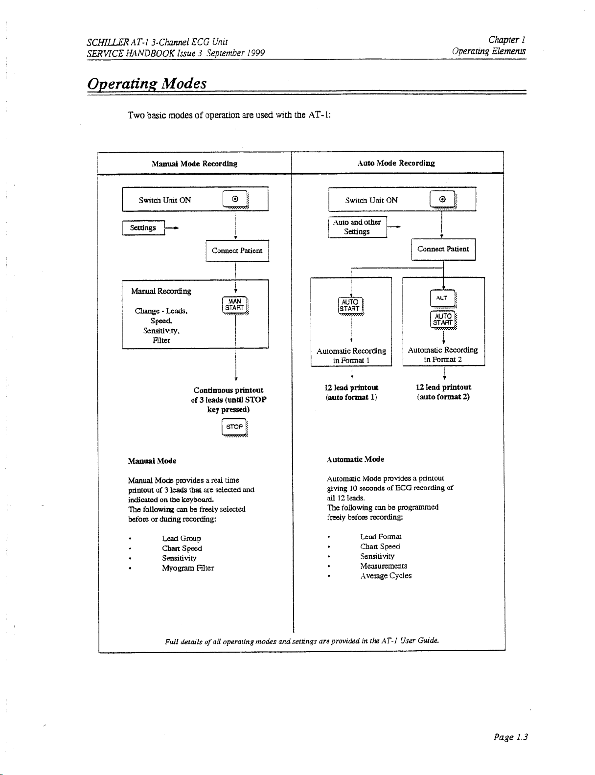
Operating
Two
basic
I
Manual
Switch
ManuaI
Change
speed.
Sensitivity,
1
Modes
modes
Mode
Unit
ON
Recording
-
Leads.
Filter
of
opemion
Recordhg
are
used
with
the
AT-
I
i
1:
1
Auto
IMode
Swtch Unit
I
j
Recording
ON
I
Connea Patient
-
I+
.............
............
I
I
Manuai
printout
indicated
?he
following
before
or
Mode
provides
of 3
leads
on
the
can
during
Lzad
chart
Sensitivity
Myogm
Full
Condnuous
of
3
rhat
are selected and
keyboard.
be
freely selected
recording:
Group
Speed
Frlter
&rolls
of
leads
(until
key
pressed)
..........
a
real
time
all operaling
printout
STOP
modes
and
selllngs
1
be
programmed
User
l2
(auto
GULL?.
12
lead
printout
(auto format
.Automatic
Automatic Mode provides a printout
gving
all
12
The following
freely
are
prowded
1)
.Mode
10
seconds
I&.
can
before
recording:
Led
Format
Chan Speed
Sensitivity
Measurements
Avenge Cycles
in
the
of ECG recording
AT-i
lead
j
printout
format
of
2)
Page I.3
Page 12

Chapter
Operanng
I
Elements
SERVICE
SCHILLER
ANNDBOOKIssue 3 September
AT-I
3-Chunnel
ECG
Unit
I999
Function
Keys
Switch
unit
on
Switch unit
Printout stored
Start
Start
Stop
off
automatic recording
manual
recording
recording
ECG
m?
;-\uTo:
m.
Id
ca
I
,iLT
4
Switch myogram riiter
A.
..........
Lead
Cancel
or
Automauc
$
Key
for
1
k
Key for initiation
pup
selector
enable
QRS
beeper
ECG
sensiuvity adjustment
ECG
automatic
Chart
only
mV
indication
of
setups
(muscle
sensitivity selector
speed
mark
on
and
tremor)
in
recording
selector
output
during
selection
of
on
or
off
automatic
(5,
second format for Auto printout
(5,
10
or
25
or
50
manual
mode
only
20
mm/mv)
mm/s)
recording
for
for
manual
manual and
recording
Page
I.4
Page 13

SCHILLER
SERVICE
AT-I
3-Channel
HANDBOOK
Indicators
ECG
Issue
3
Unit
September
1999
Chapter
Operating Elemts
I
0-
Olr
0
PAPER
0
LEADOFF
0
FILT
avR
(ti
0
v1
0
V4
aMaVF
aW
Ill)
v2
v3
V5
V6
Mains indicxor
Battery lamp
Warning
Warning
Myogram filter (lit when
Indicator lamp
(lit
when
(lit
when
lamp for end
lamp
for
loose
for
selected lead amup
mains
connecred)
mnning
of
paper
on
battery power
or
paper
jam
electrode connection
filter
ON)
I.
-
mains
II,
III
(Cabrera: an,
not connected)
I.
Indicator lamp for selected lead pup am, aVL. aVF (Cabrem
aW,
m)
Indicator lamp for selected lead pup
Indicator lamp for selected lead group
V1,
V4,
V2,
V5,
V3
V6
-am)
When the lead group
OFF
indicator
A
special lead ,goup
When
this
Note:
is
lit.
combination is selected.
The lead indicator
all
12
leads are printed
aVR,
(V1,
aVL.
II
and
ALT
!amps
aVF
is selected,
V5)
can be selected for
-
as
(downwards lead selector)
both
indicator lamps
show
the
derined
no
lead-off
lead group
in
the
auto
alarxn
manual
mode
V1-V3
and
for
manual
mode
format.
beep is sounded, only
by
pressing
V4-V6
are
lit.
mode
only.
In auto mode
the
LEAD
Page
1.5
Page 14

Chaper
Operating
I
Elements
Settings
Each
the required
number then selects
As
of
the programmable parameters
format.
a
section
a
specrfic
soon
as
the
XLT
key
is
pressed, the keyboard
is
set by means
number and one
parameter setting.
SERVICE
of
acode.
This
code comprises
or
more parameter numbers.
is
dedicated
to
the proogramrmng function.
SCHILLER
AT-I
HANDBOOK
This
combined code
3-Channel
Issue 3 Seurember
anumber
ECG
for
Unit
I999
!
t
The setting
key
the
unit
As
an example,
On
the following pages the programmable parameters
is
remembered and the keyboard
is
pressed Once the semgs have been cont'irmed, they are stored
is
mtched
if
you
Start
programming
Switch
off.
want
to
set the language
I
Key
0
Program sequence
to
numerical keyboard
/
is
only released for other funcuons when the
on
your
Key
2
I
Key
and
in
the
memory even when
AT-1
to
English,
2
proceed
CONFIRM
as
SETTING
the programming sequences are
mop
follows:
given.
L\
!
Page
,
1.6
Page 15
SCHLLER
SERVICE
HANDBOOK
AT-I
3-Chunnei
Issue 3 September
ECG
Unit
I999
Chapter
I
Operating Elements
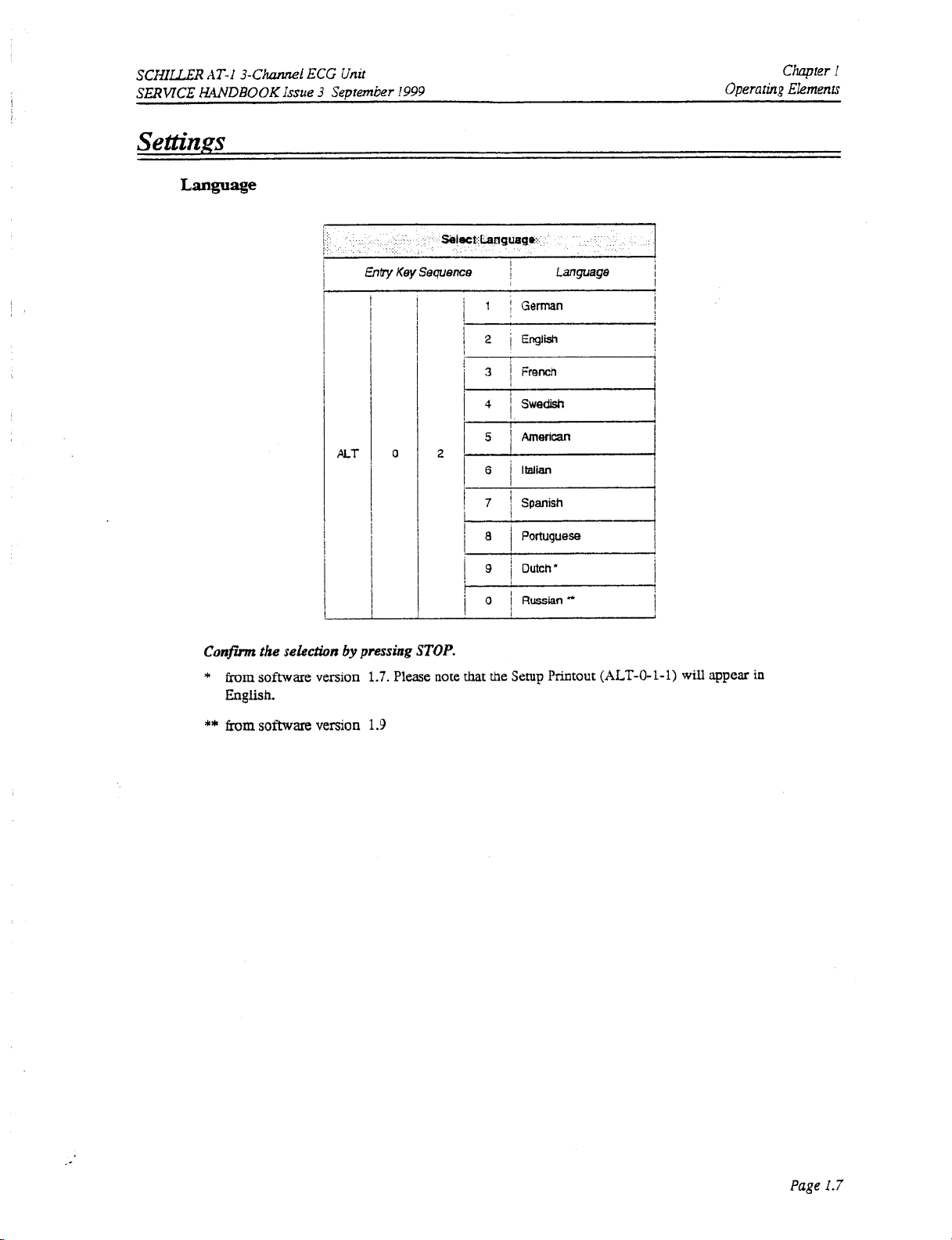
Confm
*
from
English.
**
from
the
selection
software
software
by
version
version
0
pressing
1.7.
Please
1.9
STOP.
note
i
1
I
that the
!
German
Setup
language
Printout
I
i
(ALT-0-1-1)
will
appear
in
Page
1.7
Page 16
Chapter
u.,
Operating
I
Ekments
SERVICE
SCHILLLR
AT-i
hXVDBOOK
3-Channel ECG
Issue
3
September
Unir
I999
Settings
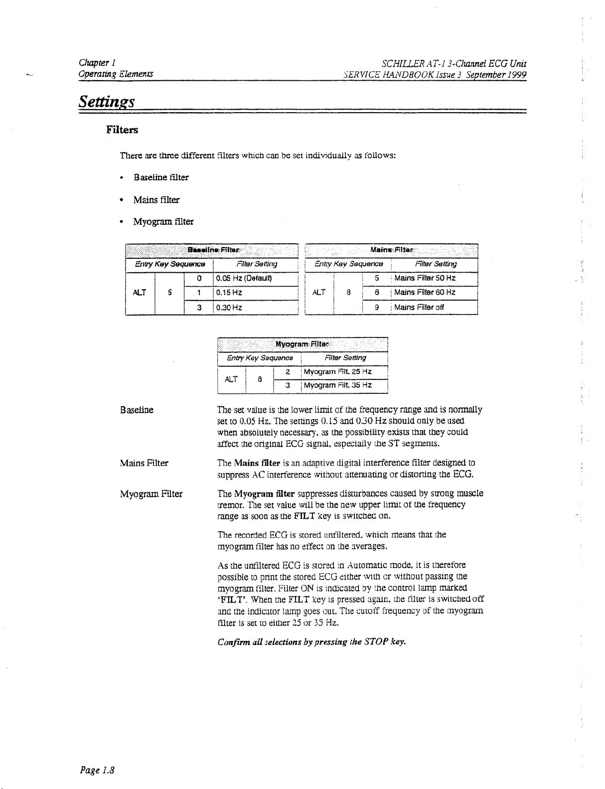
There
are
three
-
Baseline ffiter
Mains
different filters which can be set individually
filter
as
follows:
Myogram
ALT
fdter
5
Baseline
Mains
Filter
Myogram Filter
~
EntvKeySequence
0 I 0.05
1
3
Hz (Default)
10.15Hf
10.30HZ
Enby
Key Sequence
The set value is the lower
set to
0.05
Hz.
1
I
I
,
limit
The settings
Filter
Setbng
of
the frequency range and
0.15
and
0.30
when absolutely necessary, as the possibility
the
affect
The
original ECG signal, especially
Mains
fdter
is
an
adapdve digital interference filter designed
,
Hz
should only be
exists
the
ST
segments.
suppress AC interference without attenuaring or distorting the
The
LMyogram
tremor. The set value will be the new upper
range as soon
Titer
suppresses disturbances caused
as
the
FlLT
key is switched on.
limit
of
FilterSetting
is
normally
used
that they could
ECG.
by
strong muscle
the
frequency
r
I
to
Page
1.8
The recorded ECG is stored uniiltered, which means that the
myogram filter
As
the
unfiltered ECG
possible to print the stored ECG either
myogram filter. Filter
TILT'.
and
the indicator
filter is set to either
Confm
has
When the
ail
selections
no
effect on the Iverages.
is
stored in Automatic mode,
with
or without passing the
ON
is indicated
FTLT
key
is
imp
goes out. The cutoff frequency of the myogram
25
or
35
Hz.
by
pressing
by
pressed
the
the conuol lamp
sgain,
STOP
it
the filter
key.
is therefore
marked
is
switched off
Page 17
SCHILLER
SERMCE
AT-]
HANDBOOK
Settings
Lead
Sequence
Printout
Paper
3-Channel
Issue
ECG
3
September
Unit
1999
Operaring
Chapter
Ekmn
1
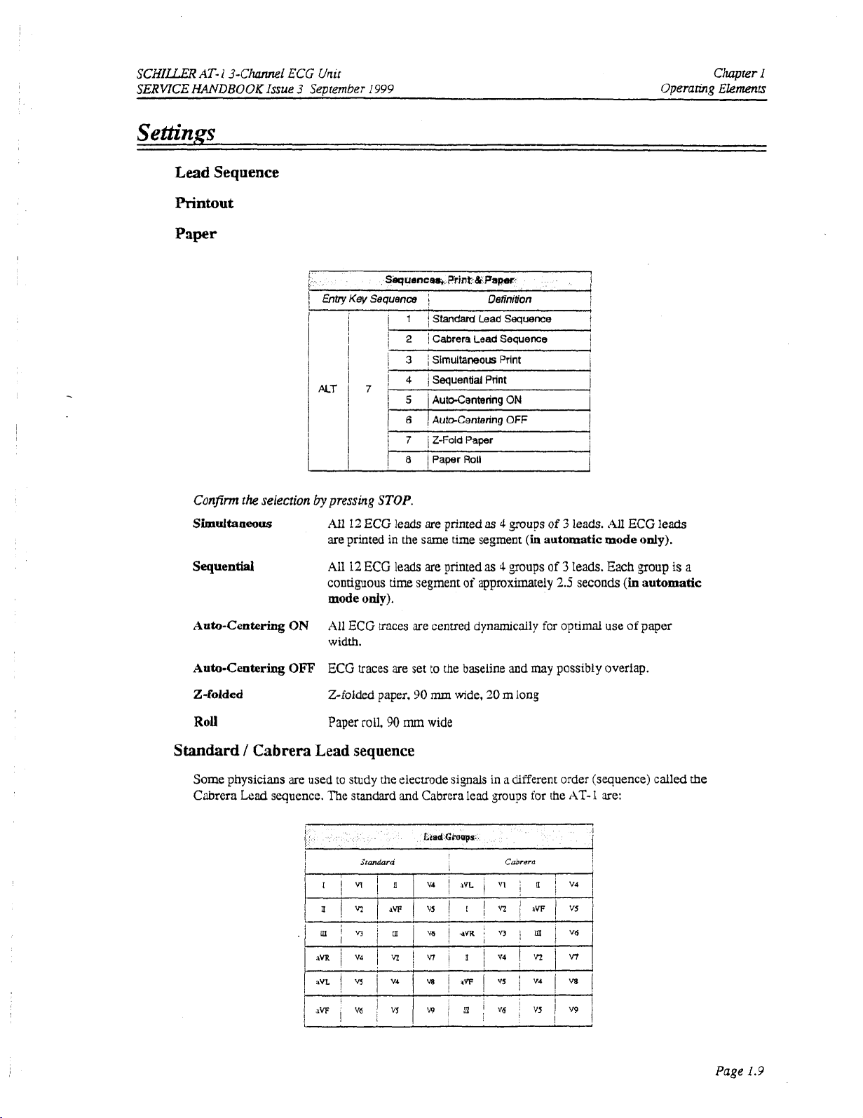
Conjirm
simurtaueous
Sequential
Auto-Centering
Auto-Centering
the
selection
I
1
~ntry~ey~equence I
I
i
i
I
I
I
I
ON
OFF
by
7'
pressing
All
12
STOP.
ECG
are printed
,411
12
ECG leads
contiguous time segment
mode
only).
All
ECG traces
width.
ECG traces are set
Sequences,
I
2
Cabrera
1
3
~
Simuitaneousprint
I
4
j
Sequentid
!
5
i
Auto-CenterinqON
I
6
Aura-Centering
1
7 1 Z-Fold
i
8 I PaperRoll
leads
are printed
in
the
same time segment
are
printed
are
centred dynamically for optimal use
to
the baseline and
Print
&
Paper
Definition
Lead
Print
Paper
as 4 groups
as 4 groups
of
approximately
Sequence
OFF
(in
may
3
1
i
!
I
i
I
I
I
I
I
of
3
leads.
automatic
of
3
2.5
possibly
mode
leads. Each group
seconds
overlap.
All
ECG
only).
(in
automatic
of
paper
leads
is
a
2-folded
Roll
Standard / Cabrera
Some physicians are used
Cabrera
Lead
sequence. The standard
I
Zfolded paper,
roll,
Paper
Lead
sequence
to
study the electrode signals
5randara
90
90
mm
and
mm
wide,
20
m
long
wide
in
a different order (sequence) called
Cabrera lead groups for the
Cabrera
AT-
1
are:
the
Page
1.9
Page 18

Chapter
1
Operarirrp Elements
SER'ITCE
SCHILLER
AT-1
HNDBOOK
3-Cilannel
ECG
Issue 3 September
Unit
I999
Settings
Two
ALT
ECG
.for
Automatic
separate
key
)as
formats
follows:
Format
Mode
for
the automatic
1
ECG
Automatic
ourput
ECG
Setup Format
cm
be selected
Format
Chart speed
Chart speed
is
IS
25
50
(1
or
mm/s
mm/s
1.
immediately
I
after
the
i
Confirm
Average
Conjinn
Note:
the
selection
Cycles
l
or
2
the
selection
Lead
by
2
by
selection
pressing
1
5
I
I
'
6
I
I
I
I
7
I
,
I
8
1
I
I
9
~
I
pressing
for
the
STOP.
average cydes are pnnted.
I
I
4
*
3
(25
mWs)
The average complexes are orinted
leads at a chart speed
4
*
3
(50
The average complexes are printed
1
leads at a chart speed
~
6
I
The average complexes are orinted
1
wtM
11
~
The average complexes are pnnted out for all
~
individually with
mrms)
2
(50
mws)
one rhvthrn lead at a chart speed
*12(25mnrls)+2'Rhy
of
25
or
50
1
*
Rhy
two
rhythm leads at
mds.
mads.
out
in four groups
out
in
out
in
of
a
chart
STOP.
2.
rhythm leads
are
defined
on
the next page.
four groups
six grouos
50
mWs.
1'2
speed
leads
of
of
of
of
25
three
three
two
mnrls.
leads
I
I
~
1
I
I
,
I
~
Page
1.10
Page 19

SCHILLER
SERVICE
HANDBOOK
AT-1
3-Chrurnei
Issue 3
ECG
September
Unit
I999
Operaring
Chapter
Elements
I
Settings
Measurements
Confirm
Selecting
.for
Automatic
the
selection
Rhythm
Measurements
by
pressing
Leads
t
'
1
ALT
'
I
I
Mode
and
Markings
Detailed table of measurement
values
5
6
of
i
suppressed.).
I
Oetailed table
Reference
j
well as end of T wave) are omitted.
i
Reference mark~ngs (beginning and end
1
well
as
end of T wave) are added
STOP.
3
j
Setup
Rhythm
4
I
SetupRhythmLead2
(Messurement
elecmcal
axes.
of
measurement results
marlcings
(beginning and end of P wave
Setup
Lead
1
intervals, and heart rate are not
lead
output
Optlon
Format
results
IS
is
to
the
only)
omitted (However,
pnnted.
and
QRS
of P wave and
ECG
cycles.
1
1
QRS
I
I
i
the
as
as
I
I
I
I
1
]
I
I
Confirm
Enay
the
Extremity
Key
Sequence
sekcrion
Leads
by
pressing
I
-Baa
1
I
EneyKeySequence
Precordfet
Leads
1
1
I
lsad
w
j
STOP.
Page
1.iI
Page 20

Chapter
Operaring
1
Elements
SERVICE
SCHILLER
HANDBOOK
AT-1
3-Chei
Issue 3 September
ECG
Unit
I999
I
I
Printout
The defined
A
pnntout
on
the
Unit designation
Serial number
Leads:
ECG
Patient
MECG:
Measurements:
Marks:
Selected
of
all
of
installed
fonnat:
data
Seftings
formars
the
rhythm
and
defined settings
software:
(AT-1).
form
leads Leads selected for
settings can be checked as follows:
ALT
-
0
-
1
-
any
number
will
be produced and gives the following information. depending
software options installed (M=Measurement)
version
Standard
Long
Enabled
Average cycles
(e.g.
Enabled
Enabled
(0001,
(+)
4
*
3
(+)
(+)
(S)
(25
or Cabrera
short
or Suppressed
as
mm/s))
or
Suppressed
or
Suppressed
(C)
(0)
or suppressed
defined
R1.
R2
rev.
in
(-1
(-1
(-1
auto
and
(-1
ECG
software
recording
,
I
-I
setup
I
Automatic centring: Enabled
Papertype: ZFolded or
Printout of signals: Sequential
Baselinefdter:
Mainsfilter: jOHz, 60Hz
Myogram filter:
0.05,0.15,
25Hz
(+)
or 35H2,
or Suppressed
Roll
or
Simultaneous
or
0.30
Hz
or
OFF(-)
On
(+)
or
(-)
Off
(-)
Page
1.12
Page 21
SCHILLER
SERVICE
HANDBOOK
AT-I
3-Channel
Issue
ECG
3
Sentember
Unir
1999
Operaring
Chapter
Ekmenrs
1
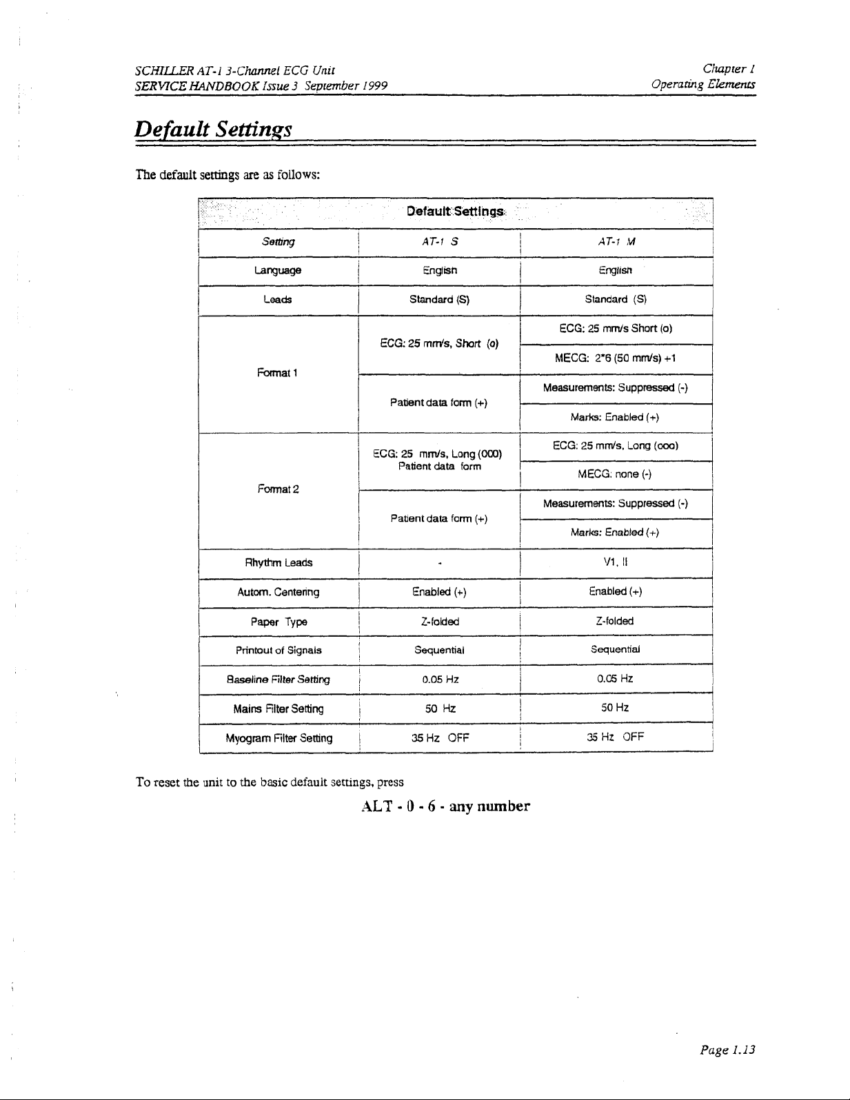
Default
The
default
settings
Settings
are
as
follows:
Semng
bng=ge
Leads
Format
Format
1
2
1
I
I
1
I
I
ECG:
Patient
Pattent
AT-1
S
English
Standard (S)
25
mds,
Short
data
form
data
form
(+)
(+)
(0)
!
I
I
I
MECG: 2.6
Standard (S)
ECG:
25
AT-;
English
mm/s
(50
!
Measurements: Suppressed
I
I
I
Marks: Enabled
Measurements: Suppressed
Marks: Enabled
M
Short
rnm/s)
j
I
i
(0)
+1
(-)
(+)
(-)
(t)
1
To
reset the
unit
Mains
to
the
basic
Filter Setting
default
I
settings,
ALT
press
-
50
0 - 6
Hz
-
any
1
I
I
number
50
Hz
1
Page
I.I3
Page 22
Chapter
Operanhg
I
Ekmenn
SCHILLER
SERVICE
HANDBOOKissue 3 September
AT-1
3-Chunnel
ECG
Unit
1999
I
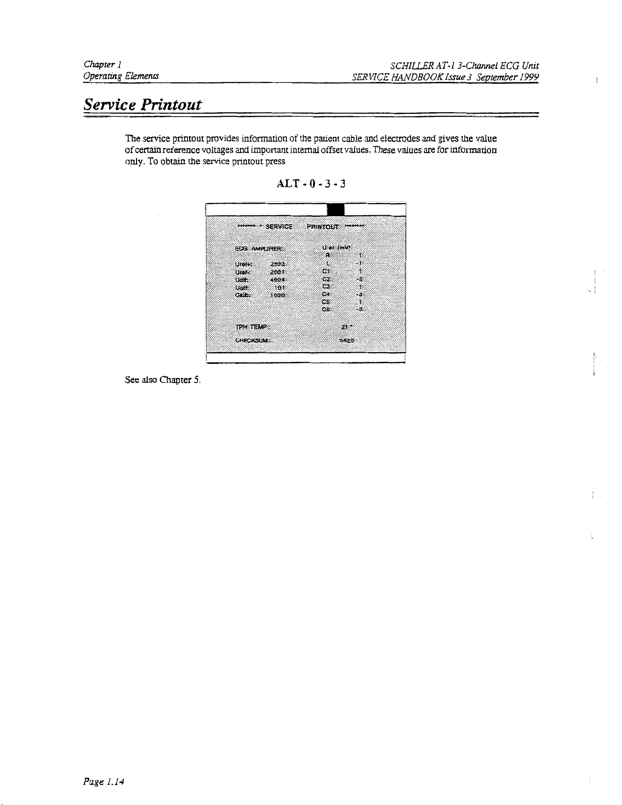
Service
The service prrntout provides
of
only.
See
Printout
certain reference voltages
To
obtain
the service printout press
also
Chapter
5.
information
and
important internal offset values. These values are
of
the patient cable
ALT
- 0 -
3 - 3
and
elecmdes
and
gives the value
for
rnformation
Page
1.14
Page 23
SCHILLER
SERWCE
EGWDEOOK
AT-1
3-ChanneL
Issue
ECG
3
September
Unit
1999
Operaiining
Chaprer
Ekmentr
I
Installing
To
Acceptance
MORE
...
Software
upgrade
the
fiT
of
THAN
AT- 1 from.
- 0 - 4 -
the
code
is
10
A'ITEMPTS
Options
for
example
followed
indicated
TO
by
by
a
ENTER
standard
the
series
to
upgrade code
of
beeps.
CAUTION
THE
M
version type the
(obtainable
INCORRECT
CODE
following:
from
Schiller)
BLOCKS
THE
W
Page
1.15
Page 24

Chapter
Operating
I
Elems
SERWCE
SCHILLER
AT-1
HANDBOOK
3-Channel
Issue
3
ECG
September
Unit
1999
-.
,
,
Page
1.16
Page 25
SCHILLER
SERVICE
HANDBOOK
AT-I
3-Chei
Issue
ECG
3
Unir
September
!999
Chapter
Functional Overview
2
Tntroakction
Control and
Power Supply
CPU
and
Memory
Control
ECG
and
Thermal
Paper Mark
Power On Reset
Stepper
Amut?@r
ECG
Isolared
ECG
Signal
Power
Supply
Processing
Power
Supply
Print Head
Motor
Conrroller
IMK
II-2
Power
board
Circuits
board
Controller
Supplies
Functional
Contents
MK
I1
-
I
MK
11
-
1
Chapter
2
Overview
2.2
2.4
2.4
2.4
2.4
2.5
2.5
2.5
2.5
2.5
2.6
2.6
2.6
Page
2.1
Page 26

Chapter
Functional
2
Overview
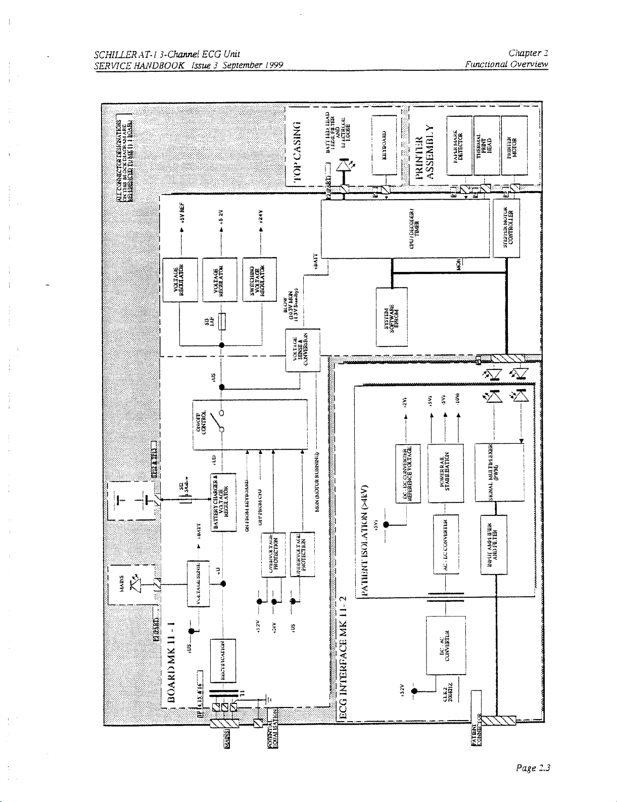
Introduction
This
chapter
to enable
modules. A functional block
the
provides
Service engineer
a
functional
SERVICE
overview
to
idenufy processing paths in order
diagram
of
supports
the
AT- 1 electronics. The
rhe
text.
SCHILLER
WDBOOK
to
help idenufy possible
aimof
AT-I
Issue
this
3-Channel
3
September
overview
faulty
is
ECG
Unit
I999
i
Page
2.2
Page 27
SCSILLER
SERWCE
fiVDBOOK
AT-I
3-Channei
issue
ECG
3
Unir
Se.ptember
1999
Chaprer
Functional Overview
3
Page
3.3
Page 28

Chapter
Funcrionai
2
Overview
SERVICE
SCHILLER
AGWDBOOK
AT-1
3-Channel
Issue
3
September
ECG
Unit
1999
Control
Power
The
35V(+U).
charges the battery wnen
voltage.
An
directly from the keyboard
overvoltage
undervoltage
The
dc supply
connected (i.e.
A
Battery low signal
compensates
only
Note:
CPU
and
Supply
mains
This voltage
ON/OFF
mains
LED
at
10.3V.
The
off
and
Processing
Power
suuply
control logic switches
on
either
is
detected
is
lit directly when
(+US)
and
the
for
voltage drop when the printer stepper motor is active
bartery voltage
(p0FF)
Supply
is
full
wave rectified
is
used
by a switched voltage generator
mains
and
the
5.2V
or
on
+us
activates signal +BAIT when the
unit
is
running
(BLOW)
when
is
is
the
board
to
produce
is
connected. When
+UD
to
three voltage regulators. The unit
then held
24V
(indicating over current) the unit
mains
on
generated when battery voltage
also
voltage
on
supplies directly switches
is
connected. The same circuit
battery power).
monitored directly
falls
below approximateiy
LMK
an
mains
from the CPU (signal
Circuits
I1
-
L
unregulated
is
unit
by
the CPU which switches
dc
supply
to
produce
not connected,
!J,PO~.
the
unit
off.
is
directly switched
also
monitors
is
switched
(+US)
falls
and
the
9.4V.
on
of
approximately
+UD
(13.jV).
+UD
is
is
Detection
Similarly when
and
mains
to 11.3V. A circuit
Blow signal
+UD
the battery
switched
off.
the
switched
is
is
active
the
unit
on
of
an
not
-.
Overall control and coordination
control functions.
of
the
AT-1
Memory
Program
An EPROM contains the unit software. The EPROM
Static
The
RAM
when the unit
Serial
The serial
Memory
RAM
Memory
memory stores
is
switched
EEPROM
EEPROM
the
off.
(U12)
ECG
data
stores the
and comprises
unit
base settings.
is
by 68332 CPU which performs
has
128
kByte
of
memory.
two
128
kbyte
RAM
chips.
all
timing
All
data are lost
..
and
.
Page
2.4
Page 29

SCMLLER
SERVICE
AT-I
3-Channel
WDBOOK
ECG
issue
Unir
3
September
I999
Funcrional
Chapter
Overview
2
Control
Thermal
!
Paper
Power
and
The Thermal
controller senalises the
applied
and
pnnter
Power
Print
hnt
to
the
head.
tmmg
Head
Head
and
are
performed
iMark
The Paper
input
1.
The Power
follows:
Mark
signal
from
to
the comparator is approximately
On
Reset
on
reset circuit controls the master reset
To
provide a delay
and
give
the
To
disable the unit
on
2oOms
if
Supply
board
Controller
is
controlled
data
for the pnnt head
thus
the intensity
the printer
initial
reset time required by the
the
+5V
by
a
pnnt
of
by the CPU.
is
fed
3.SV
switch-on
rail
drops
and
the pnnrout. Both applicauons, pnnt head conuoller
to
and
to
ensure
below
LMK
head conrroller and umer cxcuit The
the
a comparator.
when
of
68332
I1
tuner
cmmt controls how
The
this
is
present the
the
CPU.
This
that
the power supply
processor.
-
I
paper
circuit has
long
mark
detection voltage
PMARK
signal
two
is
fully stabilized
functions
+4.75V.
pnnt
current
is
logic
head
is
as
Stepper Motor Controller
The printer stepper motor speed
is
controlled
by
a timer circuit.
Page
15
Page 30
Chapter
Funcrionai
2
Overview
SERVICE
SCHILLER
HANDBOOK
AT-I
-1-Chunnel
Issue
3
ECG
September
Unit
I999
ECG
ECG
ECG
AmplQ7er
Isoiated
DUDC
Circuit.
The
are
Servicing Note:
converter
-2.OVi
stabilised
MK
Power
circuits
and the 2Vi isolatedreference voltages are
by a &nor
11-2
Supplies
produce
diode
When
used for reference.
all
the isolated power voltages required by
and voltage follower circuit.
taking
measurements always ensure
Signai
The incoming
inverting operational-ampwiers giving a gain of
(approximately
The
multiplexer sampling rate
Noise
The right leg electrode to
some
patient noise and
patient left leg electrode
ground
ECG
signals
RA.
LA.
and
1
Idlz)
and amplified by
is
1000Hz.
Damping
the
patient
is
thus
reducing incoming signal distortion,
is
phase swted
to
cancel (or reduce) patient induced
C1
to
C6
23
before being applied to
the signal ground reference signal. To assist
180".
This phase shifted signal
noise.
generated fromthe-5Vi
are
27
kHz
low-pass
11.
The signals are
the
the
the
ECG
supply.
that
the
isolated
fdtered
and
applied
further
incoming signal
is
low
multiplexer.
then used by
Amplifier
The
voltages
ground
is
to
non-
pass filtered
in
cancelling
from
the
the
signal
I
,
!
Page
2.6
Page 31

SCHILLER
SERVICE
HANDBOOK
AT-1
3-Chl
ECG
Issue
Unit
3
September
1999
Fault
Diagnosis
and
Check
Chapter
Procedures
3
Znb.Odrrctr0
Fault
General Check Procedures
Printer
‘n
Dipgnosis
Check
Chart
and
Contents
Fault
Check
Chapter
3
Diagnosis
Procedures
3.2
3.3
3.4
3.5
Page
3.1
Page 32

Chapter
Fault
3
Diagnosis
and
Check
Introduction
The
AT-
1
is designed to
1
ismodulereplacement andnot boardrepair.
procedures
procedures
An
initial
finding cham and procedures
cases
module
given
parameters
instructions for
given
If
the
settings and parameters that have been entered.
that
are
fault
the
fault
is
stated.
should
in
Chapters
initial
Procedures
be
sunple
will
quickly
designed
diagnosis chart
and
so
that test equipment
is
on
finding
be
and
charts should indicate
the
first
module
checked in the
setting-up
all
replaceable modules, along
4
and
of
the
5.
fault-finding chart
to
use
and sunple
to
The
purposeof thischapter
SCHILLER
SERVICE
HANDBOOK
service: the service ptulosophy of
is
AT-1
3-Channel
Issue
3
the
to
provide fault-finding
September
efficiently identify a fault to a specific module. Fault-finding
is
kept to a minimum.
provided detailing
the
following
given
is
the
order
given. When a module
module may
does
not indicate the area where the fault exists, re-check
all
the general fault indicadons. Use
pages to indicate a faulty area
the
most
likely
faulty
area.
one
most likely to contain the fault. Other modules
has
been replaced specific test
be
applicable. The removal and replacement
with
any setup
If
these are correct, check the software.
or
check
or
module.
When
more
procedures required,
the
In
than one
all
AT-
fault
most
are
the
ECG
Unit
I999
Page
3.2
Page 33

SCHILLER
SERVICE
XWDBOOK
AT-1
3-C;lannei
issue
ECG
3
Unit
September
1999
r'cuiit
Diagnosis
.ma
Check
Cilapter
Procedures
3
Fault
Diagnosis
Chart
Page 34

..
.
Chapter
Fault
3
Diagnosis
General
The
boardhas beenreplaced Itis not afullfunctional test(whichcanon1y
equipment
1
functional
information
relevant User
To
1.
2.
3.
4.
5.
6.
and
Check
Procedures
Check
Procedures
procedure detailed here
in
the
factory)
areas.
The
insmctions given here are guides
is
required (general settings, comprehensive menu guides etC.j please refer to
Manual for
carry
out
the
Connect
Switch
flash
Carry
Connect
Press the
good
Press the
mains
the
for a few seconds
out
the
an ECG
MAN START
quality.
AUTO
general
unit
AT-1
power
on
by pressing the
Printer Check detailed
simulator to
START
is
a
general confidence check
but
is
the
software
intended
to
provide a general confidence check in
version
applicable.
functional check procedure, proceed
to
the
unit
and ensure
ON
on
key
the
on
that
next page.
the ECG connector
key and ensure that
the
key and wait approximately
SERVICE
of
the
to
the
the
green
the keyboard. Ensure that
on
the side panel and switch on.
three
indicated leads are printed and are
10
seconds for
commence. Ensure that the printout is accurate and of good
SCHILLER
HANDBOOK
unit after
becaniedoutwithdedicated
basic
functions. Emore operating
as
follows:
mains
LED
quality.
AT-i
3-Channel
Issue
an
internal module
all
the major
lights.
the
LED
lights
the
printout
3
Sevrember
to
or
AT-
the
of
ECG
Unit
I999
i
I
7.
Switch the unit
the
battery.
8.
Disconnect
unit
on
the
battery
off
and leave connected to the
the
mains and
switch
the
unit on. Ensure that
battery power for approximately
has
limited capacity (not before
mains
supply for
an
hour. Ensure that the battery
45
minutes).
the
10
Battery
hours
LED
or more
is
lit.
LED
flashes when
to
charge
Run
the
Page
3.4
Page 35

SCHLLER
SERVICE
HANDBOOK
AT-I
3-Cmi ECG
Issue
Unit
3
September
1999
Fault
Diagnosrr
and
Check
Chapter
Procedures
3
Printer
To
To
A
lead
Carefully examine the printout and ensure
print-head pixels will be seen
Ifafaultypixelis detectedtheprintermust bereplaced. Iftheprintout isuneven (forexampledarker
at
is
been
quality.
IMPORTANT:
Print Head Alignment
Check
check
the
printer and to ensure
carry
out
the
printer check press:
test printout is given.
arrow
keys
A
up
the
top
than
at the bottom),
too
faint
or
too
dark.
exposed
to
light for a long period, or poor quality paper can
that
every pixel
ALT
Four
test patterns are avivslliable - toggle between
or
down.
as
a horizontal white line. Examine the printout for evenness of
it
indicates
check the
suobe
adjustment:Also
THE
'SHELF
INDEFLNlTE.
STORED
THAT
ADVERSELY
IN A COOL
HAS
and
Print
BEEN
LIFE'
OLD
EFFECT
is
operational, a built-in printer test is provided.
-
-MAP4
chat
that
START
all
the
lines
the printer alignment is not correct.
check
OF
TIE
PFUNTER PAPER
PAPER, PA4PER
DAMP
FREE
EXPOSED
Head
TO
THE
QUALITY
Tension
the
test
patterns
with
the
are even and unintempted. Any faulty
print
If
the
printout
the
paper: old paper, paperthat
all
adversely effect
IS
NOT
THAT HAS
ENVIRONMENT,
LYCESSIVE
OF
THE
NOT
HEAT
PRINT
BEEN
OR
CAN
has
the
print
PAPER
The
print head tension
two
spring exerting pressure
print
head
alignment
alignment
is
not correct change the paper
(the
pressure that
on
the print
is
fxed and cannot be adjusted. If the print head tension or print
the
print head exerts
head:
the print head tension cannot be adjusted.
uay
and printer assembly.
on
the
printer paper)
is
achieved
with
Similarly
head
Page
3.5
Page 36

Chapter
Fault
Diagnosis
AT-I
3
and
Check
Procedures
SERVICE
SCH1LLE.P
HANDBOOK
3-Chel
Issue
3
ECG
September
Unit
I999
I
i
Page
3.6
Page 37

SCMLLER
SERVICE
HANDBOOK
AT-1
3-Channel
Issue
ECG
3
Unit
September
1999
Module
Removal
Chapter
and
Replacement
4
Module
Introduction
Warnings
Physical
Test
Opening
Exploded
ECG
Control and
Battery
Paper
Paper
Keyboard
and
Cautions
Overview
Equipment,
the Case
view
Intel.face
Tray
Tray
Board
Power
Pack
Assembly
Assembly
Tools,
Removal
Contents
and
Accessories
IMK
11 - 2
Supply
Board
LMK
11-1
and
Thed
and
Thermal Printer
Printer
und
Chapter
4
Replacement
4.3
4.4
4.5
4.6
4.7
4.9
4.10
4.11
4.13
4.14
1.15
4.16
Page
4.1
Page 38

Chapter
Module
4
Removal
and
Revlacement
m
BASE
ASSEMBLY
To:
I
,
I
SCHILLER
SERVICE
A-
WDBOOK
I
I
AT-I
Issue
I
3-Channel
3
Seutember
ECG
Unit
I999
ASSEMBLY
MmOR
I
i
AND
!NTOP
j
1
I
i
I
1
I
ECOINERFACE
ECOINERFACE
I
I
I
I
I
I
CONTROLAM)
TOwERSUPPLY
SOARDMKII-1
ASSEMBLY
TO
ACCESS
1
1
I
I
i
MAINSTRANSFORMER
MAINSTRANSFORMER
AND
CONNECTOR
AND
CONNECTOR
r------
I
Page
4.2
Note:
The
Program
EPROM
is
mounted
on
the
Control
and
Power Supply
boardMK
11-1.
Page 39

SCHILLER
SERVICE
AT-I
3-ChanneL
HcWDBOOK
Introduction
This
Chapter
spared
at
service
containing
The prerequisites
Tools
and equipment
the
functional
ECG
Unit
Issue
3
September
provides
the
an
level.
The
following:
that
overview
must
that
checks and adjusrments
1999
of
the procedures
instructions given
be
t'uIlX.kd
before removing
in
to
rewve and replace the modules
this
chapter
are required to remove and replace
are
autonomous,
the
module
the
Module
Removal
with
each module
and
that
module and to carry out
Chapter
Replacement
are
4
Removal
Procedures
Replacement Procedures
Checks and
Any
adjustments.
a
procedure,
In-text diagrams support
points
and adjustment potentiometers.
Tests
are
detailed
that must
jumper
be
carried out after replacement.
settings, special checks or functional procedures
in
the relevant step.
the
text where required
and
provide location details
Specificwarningsandcautions are given where applicable.
could cause personal
injury.
Cautions
indicate areas
that
that
are
required
of
connectors, test
during
Wamingsindicatepotentialdangerthat
could cause damage
to
the equipment.
Page
4.3
Page 40

Chapter
Module
4
Removal
and
Renlacement
SERVICE
SCHILLER
HANDBOOK
AT-I 3-Chnnel
Issue
3
September
ECG
Unit
I999
Warnings
BEFORECOMMENCINGANYREMOVAL.
THAT THE
CABLE
CERTAIN CHECKS
TOP
ASSEMBLY
OUT
THESE PROCEDURES BEWARE THAT POTENTIALLY
ARE
PRESENT.
THE AT- 1 CONTAINS STATIC
ANTISTATIC PRECAUTIONS:
0
WHEN
THE
UNlT
and
Cautions
MAINS
IS
REMOVED.
CARRYING
ON
AN
OR REPLACE"TPR0CEDURES
POWER SUPPLY
AND
ADJUSTMEjS
REMOVED
AND
IS
SWITCHED
CAN ONLY BE CARRIED
WJTH
MAINS
CAUTIONS
SENSITIVE
OUT
ANY
MAINTENANCE PROCEDURES ALWAYS PLACE
EARTHED A"ISTATIC MAT.
OFF
AND THAT THE
CONNECTED.
CMOS
COMPONENTS;
OUT
WHEW
LETHAL
ENSURE
MAINS
WITH
THE
CARRYING
VOLTAGES
OBSERVE
I
0
PERSONNEL MUST BE EARTHED
COMPONENTS
0
ALWAYS USE
COMPONENTS
THE
UNlT
IS
ALWAYS
OUT
TAKE
ISNOTCIUMPED
THE CABLE ASSEMBLY.
CARE MUST BE TAKEN
NEVER USE FORCE.
THE PROCEDURAL
THE
PLACETHE~ONASOFT,~ON-ABRASIVECLOTHWHENC.RRMNG
MVIAINTENt-WCE PROCEDURES.
CARE
REMOVING THE TOP ASSEMBLY.
ORDER
AN
ANTISTATIC BAG
SUSCEPTIBLE TO ABRASION DAMAGE. TO
NOT
TO PLACE hNY
ORTWISTED
INEVER
STEPS
GTVM.
ANDTHATTHETOP hSSEMBLY ISNOTPLACEDON
WHEX
STRAIN
GIVEN
WHEN
HANDLING
WHEN
TRANSPORTING BOARDS
PREVENT
STRAIN
REMOVING
FOR
ON THE CONNECTING RIBBON CABLE
ENSURE
THE CABLE ASSEZUIBLIES.
EACH MODULE MUST
THAT THE CABLE ASSEMBLY
.W
REPLACING CONNECTORS.
ANY
BOARDS
SCRATCHING.
BE
FOLLOWED
OR
OR
LN
Page
4.4
Page 41

SCHILLER
SERVICE
WD30OK
AT-I
3-Channei
ECG
Issue
Unit
3
September
1999
Module
Removal
Chuprer
and
Replacement
4
Physical
The
The
the
The electronics
boardMK
supports
The
spacers.
Thethe~pnnterismountedonapapernay/thermalprinterassembly
section complete.
Because
screw
Overview
AT-1
unit
is
enclosed
top
part
contains
thermal
pnnter,
of
the
11-1,andtheECGinterface boardm
the
patient connector.
battery
is
secured
of
the plastic construction
fuirlgs.
in
a
the keyboard
the
paper
unit
are
in
position
two
tray,
contained
The
with
part
medical
with
the
the
battery
on
PCBs
are
double
of
the
case,
standard.
base
section
and
mains
two
printed
11-2).TheECGAmplifierboardMR
secured
sided
moulded plastic case.
containing
transformer.
circuit
boards
on
tape
spacers
and
the
mains
moulded
all
the
elecmnics
(control and
in
transformer
whichissecuredinthe base
threaded
metal
inserts
are
used
of
power
the
base
section.
is
secured
throughout
the
unit.
supply
11-2also
on
for
all
Page
4.5
Page 42

Chapter
Module
4
Removal
and
Replacement
SERVICE
SCHILLER
AWVDBOOK
AT-I
3-Channel
Issue 3 September
ECG
Unit
1999
Test
Equipment,
The
following
fnnctional
test equipment given here
please contact the
*
Digitalvoltmeter
*
Selection
*
Cleaning
*
Selection
*
Double-sided
*
ECG
list
tests. calibration procedures
SCHILLER
of
cross-bladed. posi-drive
agent such
of
spanners
tape
Patient
Simulator
Tools,
details
the
is
general.
as
Tricoetholine
and
tools. test
If
service
department.
Accessories
equipment
and
adjustments
specific
and
flat-bladed screwdrivers
and
accessories
that can be carried out
recormnendarion
required
for
test equipment
to
on
carry
the
AT-1.
is
required,
out
all
The
‘I
r,
Page
4.6
Page 43

SCHlLLER
SERVICE
HANDBOOK
AT-I
3-Channel
Issue
ECG
3
Unit
September
1999
Module
Removal
Chapter
and
Replacement
4
Opening
Prerequisites
The umt must be placed
mfenance
28
THE
BE
Tools
Posi-drive screwdriver
Test
The
following
ScHlLLER
Patient Simulator e.g. phantom
Top
The Top Assembly
six
screws:
Assembly,
the
Case
IS
cmed out
degrees.
WARNINGS
OBSERVED.
Equipment
test equipment
Patient Cable
Assembly
access
proceed
Removal
is
to
as
on
an
antlstauc
on
the
AT-
1.
AM)
CAUTIONS
is
mounted
required
on
to
320.
'
the Base Assembly and
the screws is gained
follows
mat
and anusmc precautions observed when any
The
room
temperature should be between
AT
THE
BEGINNING
carry out the functional test after
from
the underside
is
secured
OF
THE
CHAPTER
unit
to
the Base Assembly with
of
the
unit.
To remove
18
and
&MUST
assembly
the
Top
WARNING:
ENSURE
1.
Turn
the
unit
upside-down and rest
2.
Unscrew and remove rhe six countersunk retaining screws and washers situated
extreme corners and edges
3.
Grasping
carefully
5.
Release
6.
Gently
from
7.
Disconnect the cabie assembiy between the
the
the top and bottom
return
the
catch
lifl
the
Top Assembly and
the paper tray
keyboard.
the unit
and
THAT
THE
it
on
of
the
unit.
of
the
unit
to
the
standing
open the paper tray lid
turn
lid.
MAINS
a
soft
antistatic cloth.
to
ensure
CABLE
thar
the
IS
REMOVED.
two
assemblies cannot part,
position.
with
the printer roller.
it
slightly counter-clockwise so
Controi
and
Power Supply board
it
in
the
can be lifted away
MK
11-1
and
7.
Place the Top Assembly
on
a
soft cloth.
Page
4.7
Page 44

Chapter
Module
4
Removal
and
Replacement
SERWCE
SCHILLER
HWDBOOK
AT-I
3-Channel
issue
3
September
ECG
Unit
I999
Opening
Top
replace
To
Check
1.
that no screws or foreign bodies are loose
Inspect
2.
no visible damage can be seen.
caught.
Ensure
3.
Position
4.
cable, plug
bOXdMK
Note: It may
Turn
5.
Carefully position the Top Assembly on the Base Assembly and close the paper tray
6.
7.
Grasping
down and replace
the
the
case
Assembly
the
that
that
the
unit.
Replacement
Top Assembly proceed
alI
boards
and components
all
the
internal cable assemblies and ensure that they
all
connectors are firmly
the
Top Assembly in
in
the interconnecting cable
11-1.
be
necessary
Top Assembly slightly counter-clockwise and lift
the
two
assemblies
the
six securing screws and washers
Return
the
unit to
the
as
follows:
are
fly secured. Check for loose screws. Ensure
in
Ensure
that
home.
front
of
the
Base Assembly and without
from
to
tilt
the
Top
Assembly for the cable assemblies
to
ensure that they cannot
upright position.
the
bottom
of
the
are
no
cable assemblies are
the
Ktiyboard to the Control
it
over the paper tray
part,
carefully
in
the
extreme corners and edges
case.
in
good condition and that
strained.
crushed or
straining
and
tum
the
the
Power supply
to
reach.
unit
ribbon
lid.
lid.
upside-
!
I
i
of
Cany out
8.
the
functional check procedure
detailed
in Chapter
3.
Page
4.8
Page 45

SCHILLER
SERVICE
HANDBOOK
AT-1
3-Chunnei
Issue
ECG
3
Unit
September
I999
Module Removal
and
Replacement
Chapter
4
Exploded
L
View
t
1
,
PZandP3to
Keyboard
I
\
I
I
\,
1,
//
P
4
to
Prmt
Head
P6audPt
to
the
printer
Motor
and
MadcDetector
Paper
respeaively
Stepper
the
P5tO
ECG
Amplifier
procesSor
part
j
?ewer
supply
part
BUCK
Ba=Y
Connectors
Page
4.9
Page 46

Chapter
Module
4
Removal
and
Revlacement
SERVICE
SCHILLER
WDBOOK
AT-1
3-ChaMel
lssue
3
Seprember
ECG
Unit
1999
ECG
Interface
The ECG Interface
to
six
spacers.
Board
is
mounted above the Control
iMK
Prerequisite
The
Warnings
The
Top
Took
Cross-bladed posi-dnve screwdnver
and Cauuons at
Assembly
and
Test
the
must
be
removed
Equipment
beginning
Parts
ECG
Amplifier board.
Board
THE
ANTISTATIC PRECAUTIONS.
To
1.
Removai
ECG
AMPLIFIER
remove
Unscrew
the
the
Part
number
CONTAINS STATIC
ECG Amplifier proceed
six
screws
securing
11-
2
and
of
the Gapter
and
all
external cable assemblies disconnected.
as
detailed in Chapter
CAUTION
SENSnIVE CMOS
as
follows:
the board to
the
Power Supply boardMK
must
be
observed.
6.
COMPONENTS. OBSERVE
spacers.
11-1
andis secured
2.
Gently
raise the board
the
connector. Remove
Board
1.
2.
Checks
To
Switchon
patient
printed.
Replacement
Place the ECG Amplifier board component side down over
cable assembly to the Conrrol board
connector
Secure the board to the
prove
is
and
Tests
the
integnty
the
unit
simulator
positioned
to
gain access
the
board.
in
the cutout
six
spacer supports
to
the cable assembly
MK
1-1
1.
Place
on
the
side panel.
with
the
after Repiacement
of
the repaced board carry out the following functional
andconnectaSCHELER pauentcable to theECGconnector. Connectasuitable
io
the
ECG connector
and
press
'MAN
to
the
Control board and remove
the
six
spacers and connect
the
board
so
that
retaining screws.
START.
Ensure that
the
patient cable
check
all
the
procedure:
the
leads
are
Page
4.
I0
Page 47

SCHILLER
SERMCE
HANOBOOK
AT-1
3-Channel
Issue
ECG
3
Unit
September
1999
Module
Removal
Chapter
and
Replacement
4
Control
TheConuolandPowerSupplyBoardMK!l-1
ECG
Prerequisite
Tools
Pod-drive screwdriver
Parts
Control and Power Supply board
Board
ENSURE
and
Interface
The
Warnings
The
Top
The
ECG
and
Removal
Power
MK
and
Assembly
Interface
Equipment
THAT
THE
Supply
11-2.
Cmions
must be removed and
must
MAINS
at
the beginning
be removed
MK
CABLE
Board
issecuredtothe base
of
all
external cable assemblies disconnected
11-1.
Part
number
WARNING
IS
DISCONNECTED
IMK
the
11-1
Chapter mst
as
detailed in Chapter
trayandpositionedunderthe
be
observed
6.
BEFORE
COMMENCING
To
remove
1.
Disconnect the following connectors:
*
.
2.
Unscrew the nine spacer
the
Control
live and the neutral bayonet connectors
and
live
data
connector
paper
printer
ground connector to the
note: (the power supplies connector
removed
and
Power Supply board
the neutral bayonet connectors
to
the thennal
mark
connector
motor
connector
as
detailed
in
tixauons
MK
11-1 proceed
to
the
mains
to
the battery
pnnter
pnnt
head
to
the
ECG
the previous paragraph).
(four
on
the
mns
transromer)
as
follows:
connector
Amulifier will already have been
and
remove the board.
Page
4.
I1
Page 48

Chapter
Module
4
Removal
and
Replacement
SERVICE
SCHILLER
HANDBOOK
AT-i
3-ChaMel
Issue 3 September
ECG
Unit
1999
1
1
Control
Board
To
1.
2.
3.
and
Power
Replacement
replace
the
Position
COM-
the
the
live
live
data
paper
printer
ground
Replace
the
Supply
Control
and
and
and
Power
board
and
secure
following:
the neutral bayonet connectors
the
neutral bayonet connectors
connector
mark
to
the
connector
Board
Supply
at
the
nine
thermal printer
motor connector
connector
ECG
to
Amplifier
the
print
(detailed
board
fig
head
in
the
L'MK
MK
11-
points
to
the
to
the
previous
11-1
1
proceed
(
four
on
mains
connector
battery
paragraph)
(cont.)
as
follows:
the
mauls
and
reassemble the
transformer)
unit
Page
4.12
Page 49

SCHILLER
SERVICE
HANDBOOK
AT-I 3-CitMnei
issue
ECG
3
Unit
Seprember
I999
Module Removal
Chapter
and
Replacement
4
Battery
Pack
The battery pack
is
held
in
position
with
double sided
tape.
Prerequisite
The
Warnings
The Top i\ssembiy must be removed and
I
and Cautions
at
the begmmng
of
the Chapter must
all
external cable assemblies disconnected.
be
observed.
Parts
The
part
numbers
of
all
replaceable items
are
given
in
Chapter
6.
Battery Pack Removal
WARNING
THE
MAINS
To remove the Battery Pack proceed
1.
Ensure that the
2.
Disconnect the
away
from
SUPPLY
unit
two
the
base.
MUST
BE
is
switched
DISCONNECTED
as
follows:
off
and that the
DURING
mains
THlS
is
disconnected.
PROCEDURE
bayonet connectors and remove the Battery Pack by gently
pulling
Battery Pack Replacement
1.
Position
2.
Remove the double-sided tape protective sheet and secure
3.
Connect bayonet connectors.
Checks
Program
the Battery
and
Tests
all
static settings which
Pack
After Battery Repiacement
with
the connectors towards the inside
will
have been
lost
when the battery was disconnected.
of
the
unit.
the
Battery Pack to the base.
Page
4.13
Page 50

Chapter
Module
4
Removal
and
Replacement
SERVICE
SCHILLER
HANDBOOK
AT-1
3-Channel
Issue
3
ECG
September
Unit
I999
Paper
Prerequisite
Tools
Part
The part numbers for the
Chapter
THE
PRECAUTIONS
Tray
Assembly
The
Warnings
The Top Assembly
must be disconnected.
Cross-bladed screwdriver
Flat-bladed
Rat
ended
and
Cautions
must
screwdriver
pliers
Numbers
6.
THERMAL
PRINTER
and
at the beginning
be removed
Thermal
CONTAINS
Thermal
as
detailed previously.
Printer
Assembly,
CAUTION
IS
STATIC
Printer
of
the Chapter must
the
print
SENSI'ITW
be
observed
All
external cable assemblies
head
and
the motor are given
OBSERVE
ANTISTATIC
in
CWWHEEL
(4.
430
118)
AND
ROLLER
BEARING
(4.
CO
168)
PRINTHEAD
4.
143 115
I
i
i
Page
4.14
Page 51

SCMLLER
SERVICE
hkVDBOOK
AT-I
3-Chl
ECG
issue
Unit
3
September
I999
.Moduie
Removal
and
Replacement
Chapter
4
Paper Tray Assembly
PrinterRaper
1.
Remove
data
paper
pnnter motor connector
ground connecfor to the print head
2.
Unscrew the four retaining screws and remove the complete paper tray/printer assembly.
Thermal Printer Removal
1.
Turn
the
screws.
2.
Gently remove the printer taking care
Thermal
To
replace
1.
Position
slot
into
that
the
strained.
tray
Assembly Removal
the
followng connectors from the
connector
mark
Paper my/printer assembly upsidedown and unscrew the
Printer
the
Thermal Printer proceed
the
Printer in the paper tray/print assembly
the dedicated cutouts
cable assemblies from
to
connector
Replacement.
and
the thermal printer
Thermal Printer
to
retain the
as
follows:
in
the
assembly: secure
the
printer to the Interface PCB
Control
and Power supply board
two
pnter
two
tensioning screws.
so
that
the
printer mounting plate
with
the two retaining screws.
are
not caught and are
h4K
11-1
retaining
:
lips
Ensure
not
2.
Using a suring compressor. insert
positioned over the moulded spring supports and
mounting plate.
the
two
tensioning springs
in
PrinterPaper tray Xssem bly Replacement
1.
Position and secure
2.
Reconnect
3.
Replace the
Checks,
Check
the
the
data
paper
printer motor connector
ground connector
Tests
pnnt quaiity
connector
in
the
base
the assembly
following connectors to the
to
the thermal printer
mark
connector
to
the print head
Top
Assembly.
and
Adjustments after Printer
as
descnbed
in
Chapter
with
Contlol
3.
so
that the springs are
the
indent (hole) in the printer
the
four
retaining screws.
and Power supply board
Replacement
iw(.
11-
1
:
Page
4.15
Page 52

Chapter
Module
4
Removal
Keyboard
The
keyboardcomes
keyboards
and
Replacement
are
given
as
acomplete
in
Chapter
assembly
6.
with
the
SERVICE
top
casing.
SCHlLLER
HANDBOOK
The
parts
AT- I 3-Cltannei
Issue
numbers
ofthe
ECG
3
September
various
Unit
I999
f
Page
4.
I6
Page 53

SCHLLER
SERMCE
HANDBOOK
AT-I
3-Ciuuulel
Issue
ECG
3
Unit
September
1999
Chapter
Adjustments
5
Introhction
Warnings,
Test Equipment
Test Setup
Control Board
Battery
ECG
ECG
Service
Sofhyare
Cautions
Chruge
Amplifier
Ampiifir
Printout
and
Settings
and
Conditions
MK
I1-1
Component
VoUage
+ZV,
-2V
and
PWM
reference vohge
Contents
Location
Ramp
Time
Adjustment
Chapter
5
Adjustments
5.2
5.3
5.4
5.5
5.6
5.7
5.8
5.9
5.10
5.11
Page
5.1
Page 54

Chapter
Adjustments
5
Introduction
This
Chapter
procedure
equipment necessary.
required
In-text
points
is
on
diagrams
and adjustment potentiometers.
SERMCE
provides
self-contained
the
the procedures
and
Any
adjustments.
necessary
details
the tools required
jumper
to
check and adjust
settings.
special
module. or on associated modules or software. xe
support
the text where required and provide location deas
SCHILLER
HANDBOOK
all
to
carry out adjustments, and
checks
or
also
demied
AT-I
service settings. Every
functional
of
connectors,
3-Ciuuutel
Issue
tesrs
3
September
the
test
that
are
test
ECG
Unit
1999
Specific
The
part
The
AT-1
Battery
ECG
2)
We
recommend
warnings
numbers
has
the
Charge
and
cautions
for
all
replaceable
following
Voltage
are
adjustments:
(VR4
on the Microprocessorflower
Amplifier reference voltage
that
the
refenmce voltages
given
modules
and
in
rhe text where applicable.
are
given
in
Chapter
(VR3
and
VR3
on
the ECG Amplifier
are
checked
every
year.
6.
supply
Board
MK
Board
11-1)
MK11-
,
Page
5.2
Page 55

,
SCHILLER
SERVICE
AT-i
3-Chmi
IteVDBOOK
ECG
Issue
Unit
3
September
1999
Chapter
Adiusrmenrs
5
Warnings,
I
iMAINS
DISASSEMBLING THE
DISCONNECTED
CHEcz(s.
THE AT-1
PRECAUTIONS.
PLACE THE
EARTHED
ANTISTATIC BAG
CARE
USE
THE
ORDER
Cautions and Conditions
POWER
OR
CONTAINSSTATIC SENSmCMOS COMPONENTS;
WHEi'i'
MUST
FORCE.
PROCEDURAL
GIVEN.
WARNING
IS
POTENTIALLY
UNIT.
BEFORE
ADJUSTMENTS.
CARRYING
LETHAL
ADDITIONALLY
OUT
-
DISCONNECT
M
ENSURE
MA"
THE
MAINS
THAT
THE
ANCE. CALIBRATION,
BEFORE
MAINS
IS
CAUTIONS
OBSERVE
WHENCARRYINGOUT~MAIN~ANCEPROCEDURESALWAYS
UNIT
ON
XN
HANDLING
WHEN
BE
TAKEN
NEVER
EARTHED
TRANSPORTING
WHEN
STRAIN
STEPS
THE
GIVEN
ANY
RFMOVING
ANTISTATIC
BOARDS OR COMPONENTS.
BOARDS
I-WD
CABLE
FOR
ASSEMBLES.
EACH MODULE MUST BE
MAT.
OR
COMPONENTS
REPLACING
PERSOIWEL
CONNECTORS.
FOLLOWED
ANTISTATIC
WAYS
MUST
USE
NEVER
IN
BE
AN
THE
THE
OUTER
PREVENT
Conditions
The
unit
must
matntenance
The
room
temperature should be between
SURFACES
SCRATCHING.
be
placed
is
camed
OFTHEAT- 1 ARE SUSCEPTIBLETO ABRASION DAMAGE.
on
out
on
ALWAYS
an
antlsrauc
the
AT-
i.
PLACE
ma1
I8
and
ON
A
SOFT.
NON-ABRASTVE CLOTH.
and
anustauc precauuons observed when
28'
C.
TO
any
Page
5.3
Page 56

Chapter
Adjustments
5
SERVICE
SCHXLLER
AT-I
HANDBOOK
3-Channel
Issue
3
ECG
September
Unit
1999
Test
Equipment
The
following
board
checks
The
list
test equipment can
Proprietary
0
ECG
0
Oscilloscope
0
DigitaiMultimeter
0
Standard
pliers
0
ScHlLLER
proprietary
and
adjustments
of
proprietary
Test
Emulator,
tool kit
and general tools
10
and
dedicated test
on
rhe
equipment
be
obtained
is
from
not
EquipmenUToois
e.g. Phantom
with
lead
patient
a
seiection
cable Number
320
equipment
AT-1.
is
required
to
fault
comprehensive. Recommendations
the
SCHILLER
of
cross-bladed,
Service Deparrment.
flat-bladed
2.400070
(2.
and
jooO71
posi-dtive
for
frnd
and
carry out
of
suitable proprietary
screwdrivers,
USA)
all
Page
5.4
Page 57

SCHILLER
SERVICE
HANDBOOK
AT-
I
3-Channei
ECG
Issue
Unit
3
Seprember
1999
Chaprer
Adjustments
5
Test
Setup
Page
5.3
Page 58

Chapter
5
Adjustments
SERVICE
SCHIW
AT-I
HANDBOOK
3-Cha~meL
Issue
3
ECG
September
Unit
1999
Control
3oard
MK 11-1
TP??
Component
BATERY
VOLTAGE
.'
b
Location
CHARGE
(VR4)
I
SI2
EATERY
CHARGE
1.5
A
slow
NSE
Page
5.6
SU
5.2
1
I
V
FUSE
him
Page 59

SCHILLER
SERVICE
WDBOOK
AT-1
3-Chmel
Issue
ECG
3
Unir
September
1999
Chapter
Adjustments
5
Battery
Precautions
The
mmtenance
Took
Procedure
The
5
Charge Voluge
and
Requirements
unit
must
be
placed
on
m
anastatic
is
cam&
out
on
the
.AT-
and
Equipment
Digital voltmeter
SmaU
flat
bladed screwdriver
Resistor
batterychargevoltageisnominally
mA).
DISCONNECT
Disassemble the unit
Remove
two
multimeter
2.7
kOhms.
Adjust and check as
50
THE
iWS
as
the
two
battery connectors and connect
connectors
(TP12
across
the resistor.
mW
follows:
SUPPLY
detailed
and TP13)
mat
and antistatic precautions observed when
1.
The
room
temperature should be between 18 and
13.5
V(withanominal~rncurrentofappro~e1y
in
Chapter 4 and remove the
a
2.7
to
simulate a discharged battery. Connect the
kOhm
ECG
250
mW
Amplifier
resistor
MK11-2.
across
digital
any
28O
C.
the
Connect
mCISECARE-
Adjust
Disconnect
the
VR4
Mains
to
obtain a charging voltage
the
mains
supply.
WARNING
BE
AWARETHATPOTENTIALLYLETHALVOLTAGES
of
13.5
V.
supply
and
reassemble the
unit
as
detailed
in
Chapter
AREPRESENT
4.
Page
5.7
Page 60

Chapter
AdjurmKtS
3
SERVICE
SCHILLER
1Lt4NDBOOK
AT-I
3-Ch~nneL
Issue
3
ECG
September
Unit
1999
ECG
Amplifier
The
z2
V
voltage ra& generated
measurement
Note: The
THE
3V
AT
THE
Tools,
Digital voltmeter
Small
Procedure
DISCONNECT
Disassemble
Remove
side
the
and
ECG
checked withour disassembling
later
in
REFERENCE
SAME
Equipment
flat
bladed screwdriver
the
screws securing
of
the
unit
top assembly
t2
K
-2V
and
on
PWM
(Pulse
Width
board reference voltage
rhrs
chapter.
VOLTAGES,
TIME.
and
Material
THE
iMAINS
the
unit
as
component side
on
its
detailed
side
in
SUPPLY
the
uD.
front
P
WM
the
ECG
Modulauon)
is
given
the
umt
.WD
THE
in
Chapter
ECG
Reconnect
4
Amplifier board
of
the Base assembly
Ramp Tt’me
Xmplifier
cmuits.
on
Full
PWM
the
keyboard
board
the
service pnntout and can be
demls
RAMP
MKIl-2
are
used
of
the
smce pMtout are given
MUST
BOTH
and gently place by
to
the
control
as
shown below.
Adjustment
as
a
reference by
BE
ADJUSTED
the
board and place
the
I
Remove
the
EMC
shield
I
fron
the
ECG
Amplifier
board
Page
5.8
Page 61

SCHlLLER
SERVICE
AT-I
3-Channel
HANDBOOK
ECG
Issue
Unit
3
Sevtember
!
999
Chapter
Adjustments
5
ECG
Amplifier
Switch
the
unit
2V
reference
achieve a voltage
Obtain
a
service
on
reference
on
and
measure the voltage difference between the
pins
1
and
7
of
operational amplifier
difference
pnntout
of
by
pressing
4000
ALT
voltage
mV
tz
mV.
-
0
-3
-
any
key
U100.
Adjust
+2V
reference
trimmer
VR2
and
to
the
-
Ensure
that
the Udiff
Reassemble
sexvice
reading
ptout.
the
the
Uref+
is
4000
unit
and
the Uref- measurements are
mV
Adjust
VR3
as
detaled
in
Chapter
to
acnieve
4
Xecheck
00th
3000
a
Udif
reading
the voltage
mV
by
C
20
mV.
of
40o0
agm
Ensure
mV
f
obtauung
20
a
that
mV.
Page
5.9
Page 62

Chapter
5
Adjusmnts
SCHILLER
5ERVTCc'hkVDBOOK
AT-I
3-Channel
Issue
3
September
ECG
Unil
I999
Service
The Service
of
only.
The
engineer;
obtain
ECG
Printout
prrntout provides
certainreference
service
printout also gives variable settings and measurements
to
carry out these adjustments some
the
service
Ref.
Voltage
voltages
iniormauon
and
important
of
the pauent
cable
internal orfset values. These
of
~e settings require additional test equipment.
printout press the following key sequence:
UT
-
0
-3
-
my
key
This
pmwdes measurements and
for
accurate measurement
oi
ECG
semng
slpnals
faalities
and zlecwdes
chat
values
can
be
and
are
set
gives
for
by
for rhereterence voltage used
the
value
information
the service
To
'.
.
EIecuode dc offset
depend
expected are
0
0
Uref-
This gives the value
rnuluplexer cncuit
reference voltage
Uref
Udif
-
Thxs
;\mplifier
mV
This
-and Uref
uoif
This
c'xcuit. This
Calib
This
value
This
gives the
voltage
drop
the pauent cable or pauent
leg
the left
indicate
zlecmde
any
cable
on
where the elecrroaes are
3s
follows:
and
short
all
cucm
With pauent connec:ed
With pauent sirnulator connecred
pauent
simulator used and nust
With
all
zlecuodes shorted together:
of
the reference voltage used
on
the ECG Amplifier. The valueofthe
is
3000
mV
220
is
3
negauve reference voltage sed
board.
The
value
of
ths
-30
rnV
is
che
sum
of
[he
:wo
reference values above (Uref
-I.
3s
value must be
1s
'he value
value
is
i000
in
s!ecuode.
other
ts
or
of
vam
snould be
!s
[he
Uuif
5
rne
?men[ ::able
The value given
z!ec'mYeS.
open
CXC'JIIS.
connected.
-
z
10
mV
-
be
difset voltage
in
rhe
.ialue divided
md
is
The measurements
Tne
measured voltage
The voltage rezlings that
z
20
mV
taken
as
-
z
20
mV
in
mV.
on
the
ECG
voltage should
4000
mV
on
range
by
can indicate any fauits
the dc voltage between
-
ths
will depend
3
flexlble measurement.
i
20
the
muluplexer
=
150.
3.
The
obtaned
value
be
-2000
mV.
nomtnal
will
will
can
on
the
in
be
the
Page
5.10
TPH
Temp
Checksum
This
IS
the temperaturee
This
is
the
No
pauenr cable connected:
or
rhe
EPROM
check
sum.
=
100
mV
rhermal pnnt head.
The
value
my
change arter a software update.
Page 63

SCHILLER
SERVICE
hWWBOOK
AT-]
3-Channel
Issue
ECG
3
Unit
September
1999
Chapter
Adjustments
5
Software
The
software
The
only
settings
Details
instailing
To
update
Acceptance
MORE
and
option
press
of
all
the
ALT
of
THAN
Settings
version
of
the
available
rhe
following
sertLtgs
Software
- 0 - 4 -
are
AT-1
from.
the code
10
AlTEMPTS
options
followed
is
unit
and
the
options
is
the measurements
key sequence:
ALT
given
in
the
AT-I
for
example
indicated
by
TO
standard
the
by
a
ENTER
installed
option:
- 0 - 1 -
User
update
series
an
any
Guide.
to
M
version
code (obtainable
of
beeps.
CAUTION
THE
INCORRECT
are printed
M
is
printed.
key
type
CODE
on
the
bottom
To
obtain a printout
the
following:
from
BLOCKS
of
all
printouts.
Schiller)
THE
of
UNIT
ail
Page
5.1
1
Page 64

,
Chapter
Adjustments
5
SERVICE
SCHILLER
AT-
HANDBOOK
I
3-Chunnel
Issue
3
September
ECG
Unit
1999
Page
5.12
Page 65

SCHILLER
SERVICE
HANDBOOK
AT-I
3-Channel
Issue 3 September
ECG
Unit
1999
Chapter
Spare
6
Purrs
ordering
spare
Parts
Information
Contents
Chapter
Spare
6.2
6.3
6
Parts
Page
6.1
Page 66

Chapter
Spare
Pans
6
SERVICE
SCHILLER
WDBOOK
AT-I
Issue
3-ChanneI
3
September
ECG
Unit
1999
Ordering
Your
local reuresentauve stocks
of
difficulty or
will
be pleased
The
address
SCBILLER
Sales
AItgaSse
(38-6340
Switzeriand
Phone
Fax
When
Part
Part
Your
hfomation
to
obtain
the
to
help process
for advice
Department
68
Baar
Number
1Vumber:
ordering,
Description
Number
Address
is:
AG
(Order
MI41
:
MI41
state that the order is for
all
the disposables and accessones available for
address
of
your
your
order or
Processing)
766
42 42
761
08
80
an
local
to
AT-
dealer,
provlde
1
unit
please contact
any
details for
and provide
the
all
the
following:
the
AT-
head
office.
SCmLER
1.
Incase
Our
staff
products.
Service
If
If
you
Phone
Far
you
need help
Number:
contact
Department
Number
serial number for
software version
accessories
from
our service engmeers, please contact the following numbers:
i4141
:
41
41
us
by
fax.
be sure
your
AT-
used,
model and cable number.
766
761
to
provide the
1
42
03
85
34
following
infomuon:
Page
6.2
Page 67

I-
SCiaLLER
SERVICE
AT-i
3-Ciu2nnei
WDBOOK
TechnicsJ
Available
ECS
Unit
hue
3
September
Data
Con,tiguratwns
&'999
Contents
Chapter
Technical
1.2
7.3
Chpter
Tech
rcal
Da
7
ra
7
Data
Page
7.1
Page 68

SCHILLER
SERVICE
HANDBOOK
AT-1
3-Chan7wi
Issue
ECG
3
Unit
September
I999
Chapter
Spare
6
Parts
Spare
Parts
DESCRlPTION
Microprocessor and Power Supply
ECG Amplifier Board MK
Paper Mark Sensor Board
AT-1
Software
Bottom
Top Housing
Top Housing
Top Housing
Top Housing
Top Housing
(Prugrammd
Housing Complete
with
Keyboard Complete
with
Keyboard Complere (English)
with
with
Keyboard Complete
with
MIS
Keyboard Complete (French)
Keyboard Complete (Portuguese)
Paper Tray and Printer Assembly Complete
Paper Tray Lrd
11-2
11-5 1
EPROM)
Board
(German)
(Spanish)
MK
11-1
PART
NUMBER
3.
24
20
3.2421
3.
24
23
4.999
940
3.910 960
3.910 961
3.910 962
3.910 963
3.910 964
3.910 965
3.910 966
3.910 967
2
103,Cy
-
C04G
Ground Shield
Transformer Shield
ECG Isolation Shield
Mains
Socket Complete
Mains
Fuse Holder
Mains
fuse
-
2OOm/AT
Mains
Transformer
12V
Lead
Acid
Bmery
Printer Motor Comulete
Pnnt
Thennal
Thennal Print
Head
Head
Cable
Printer Roller
Potential Equalisadon Stud
4.416 028
4.
416
027
4.435 198
4.
270009
4.210
049
4.210 010
066
4.320
4.350 024
4.330 019
1.
140
115
4.520 378
4.
410 181
4. 260 377
Page
6.3
Page 69

Chapter
Technical Data
7
SERVICE
SCillLLER
kWVDBOOK
AT-1
3-Channel
Issue
3
ECG
Unit
September1999
Y
Technical
Technical
Dimensions
Weight:
Mains
Battery:
Power
LtZId.5:
Paper
Sensitivity:
Chart Paper:
printing
Recording
Data
data
subject
(yw/h):
Supply:
Consumption:
Speed:
Process:
Tracks:
to
change without notice.
290
x
210
x
69
mm
2.9
ke
~ ~~ ~~ ~ ~~ ~~
100 to
115
/
220
to
340
VAC,
50160
Hz
Bullt-in
Recording:
Standard 1 Cabren
5
manually selected
Themoreactive
-
-
High-resolution
3
automatic baseline adjusrment
12
V
!ead-acid battery (rechargeable)
7-8
VA
max.
/10
I
20
mm/mV,
2-folded,
Roll,
channels, positioned at optimal width
either automatically adjusted or
90
mm
wide, perforation
90
mm
wide
(only
on
certain
thermal
print head 3 dots per
90
markets)
on
80
mm
mm
mm.
or
I
I
I
Auto
matic
Data
Record:
ECG
Storage:
Frequency
ECG
hmpiifier:
Myogram
Filter
Lead
Programs:
Range
(musde
of
Digital
Recorder:
tremor
filter):
3
channel representation
standard
-
Version
ECG
axes),
rqerence
-
-
-
-
-
-
-
-
-
-
-
-
25
waveform). The stored
without filter.
leads
~~ ~ ~~~ ~~ ~ ~~
Listing
of
IM:
measurement
uverage
Hz
or
complexes
markings.
Memory for
Circular input memory for
0
to
150
HZ.
i)
to
150
HZ
Simultaneous, synchronous iegstration
3
active elecuode signals
Sampling frequency:
Digital
resolution:
Dynamic range:
Max.
electrode potential:
Time constant:
Frequency response:
Input impedance:
35
Hz.
programmable
of
ECG
recording data
results
10
s,
12-lead ECG
(EC)
(MA)
ECGs
12
simultaneously acquired
(intervals,
with
optional rneasuremenr
1000
5
,uV
210
>3.2
0.05
>I0
(not
can be printed with or
amplitudes,
10
s,
12-lead ECG.
(=
12
standard leads)
Hz
mVAC
5300
s
to
150
Hz
MR
active
mVDC
(-3
on
averaged
electrical
of
all
dB)
I
1
I
I
I
I
I
I
Page
7.2
Line
Frequency
Filter:
Distortion-free suppression
sinusoidal interferences by means
filter.
of
superimposed
of
an
adaptive
50
or
60
digital
Hz
I
I
Page 70

SCHIUR
SERVICE
HANDBOOK
AT-I
3-Channel
Issue
ECG
3
September
Unit
1999
Chapter
Technical
7
Data
Technical
Patient
Patient
Safety
Standard.
Safety
Class
Environmental Conditions:
Contrd
Available
The
CARDIOVlT
Standard Version:
Version
Version
Data
Input:
Leakage
Panel:
Configurations
M:
C:
Current:
AT-
1
is
available
Fully floating and isolated, defibrillaaon protected
duA
BF
I
Temperature, Operating:
Temperature.
Relative
Atmospheric pressure:
Rubber keys.
in
two
different versions:
Unit
Unit
Unit
NOTE
CERTAJN
according
according
to
Storage:
humidity:
with
ECG
with
additional
with
measurement
!
:
THIS
COUNTRIES.
to
IEC
601-1
IEC
501-
recording
ECG
VERSION
and IEC
10"
-
25
700
and
601-2-25
to
40"
C
10"
to
5.5"
to
95%
(non
to
1060
printout capabilities.
measurement
program
IS
ONLY
(M)
and interpretation.
MARKETED
C
condensing)
hPa
program.
IN
Page
7.3
Page 71

Chapter
7
Technical
Daxa
SERVICE
SCHLLER
AT-
hWVDBOOK
I
3-Chnel
Issue
3
ECG
September
Unit
I999
Page
7.4
Page 72

SCHILLER
SERVICE
iWVDBOOK
AT-1
3-Channel
Issue
ECG
2
Unir
JuLV
I998
Chapter
Glossan.
8
Introduction
Acronym
Contents
Chapter
Glossary
8.2
8.3
8
Page
8.1
Page 73

Chaprer
8
Glossary
Introduction
The
following
diagrams
Only
and electronic
for
abbreviations
list
provides
the
SCHILLER
that
are
abbreviations
a
glossary
instnunens.
specific
are
not
of
the
They
to
SCHILLER
included.
important
will
not
equipment
signals
all
appiy
are
SCHILLER
SERVICE
and
acronyms
to
the
included
AT-I
HANDBOOK
used
in
AT-
1.
here.
General
3-Channel
ECG
Issue 2 Julv
the
circuit
electrical
Unit
I998
Page
8.2
Page 74

SCHILLER
SERVICE
AT-1
3-Clmnel
IteVDBOOK
Acronvms
ECG
issue
2
Unir
July
1998
Chapter
Glossary
8
..os
A(
1
..d
ALBEEP
ANAL
AS
BAT"
BA?TLC
BAW
BLOW
CHNI
CIF(0..16)
ANA2
..
Offset signal ion the ECG amplifier)
CPU
Address
Alarm
signal is about
Analog
Address
Signal
Analog
bactery.
Battery voltage
processor
Battery less
the battery voltage drops
switched od These values apply
other equipment the
ECG
signal multiplexer control signals (on the
Communication interface. General conmi signals for
communication interface circuits.
Bus.
beeper
signal
to
the audio amplifier. The frequency
1000
Hz.
input from
strobe
to
CPU indicaring battery operation
signal
to
the
expeximentai inputs
to
the processor giving the charge condiaon of the
-
analog signal from the power supply
assess battery or
than
113.
Limits
mains
operation.
LCD
flashes when
to
below approximately
to
equipment with
are
different.
DC1
and
this
signal is active. When
9.4V
ECG
of
DC3.
used
by the
the
unit
12
V
battery. For
Amplifier)
the
this
is
CI(O..lO)
CO(O..lO)
1
CL
CL2
CLK..
cs..
CTS
D
(0..15)
DACWR
DIO..
DMUX
DWV
RS
interface control lines - input.
RS
interface control lines - output.
19
kHz
LCD
latch
pulse.
3.1
1
MHz
LCD
clock frequency.
Clock Signal. The number following
19
For example CLH
Chip select. The general format
followed
which
chip seiecr signal
signal fot the
Clear
Data
Digital
Data inpudoutput on the Data
Data multiplexer.
Dynamic
by
some charmers. The characters indicate the device
tne
chip select
EPROM
to
send. Gened signal used in
Bus
/
analog
RW
indicates a frequency of
of
signal
apperms. For example CSRTC is
for
the real time clock
etc.
converter wire.
I/O
the chip select signals
connector
the
CLK
indicates the frequency.
19
and
CSEPROM
data
communication.
MHz.
is
Cs
to
the
is
the
select
DRC(0..6)
DS..
DyTlamic
Data
suobe.
RAii
control.
Page
8.3
Page 75

Chaprer
8
Glossarv
Acronvms
SCHILLER
SERVICE
AT-I
3-Channel ECG
HANDBOOK
Issue
2
Juiv
1998
Unit
DSP..
DTXCK
DTR
ECGl
ECGMUX
ECGO
EF
EJCT
EKGRES
FFOR
FL&M
FPLN
FWR
Digitai
Transfer
signal
processor
data
acknowledge.
ion
program
Bus
signal
dam
Outgoing serial
ECG
in
-
The multiplexed ECG signal
ECG out - serial ECG
the
optical interface.
Empty
tlag.
data
serial ECG
tuns
modem
dam
to
the CPU sent over the
from
amplifier
control
on.
the ECG
Eject (paper tray).
si,d
to
the
ECG
Reset
Amplifier
First
in
to
first
out
recenter the
read.
Control signal for
.hpMier.
ECG image
frame
synchronisation
T~IS
Input for floating point co-processor.
Rag
read / write.
pack).
to acknowledge transfer of
optical
interface.
amplifier.
dam
from
the
CPU
sent
si@
resets
the
ECG
on
the LCD.
of
the
LCD.
over
HEV
HSYNC
IPLO..:!
IREG
ISYS
KB
..
KBBEEP
KB
CLR
KBCLl
'KB
CL3
KBIN..
KBS..
KONV
LA
For
Output enable signal
thermal
Horizontal synchronisation (video
Interrupt priority level
(binary
print
head
/
VGA output).
encoded).
dam
(History
Control signal from the current detector and limiter circuit
power supply
Interrupt system
Keyboard
Keyboard beep
data
to
regulate
(2
supply.
Wz).
in.
(to
audio amplifier).
Keyboard clear.
Keyboard clock.
Keyboard clock.
Keyboard
from the keyboard
to
the
CPU.
data
in
-
serial
data
Keyboard Strobe.
Conven
signal initiates the conversion
or'
the
incoming
-
this
from rhe ECG .ArnpLifer..
.kn.
Left
enable).
on
the
signal
Page
8.4
LCA
LCDAS
Liquid ~xysral address - enable.
LCD Address Strobe.
Page 76

SCHLLLER
SERVICE
AT-1
HANDBOOK
3-Channei
ECG
Issue
Unir
2
Julv
1998
Chapter
Glossary
8
Acro
n
vms
LCDKONT
LCDW
LD
1.2.3.4
LDS
LED
(0.3
LEDB
LEDMAINS
LOE
LP
LSRAM
LWE
M
LCD contrast - sets
backlight
LCD Write.
Lower
Lower
Operate signals to
Battery
Signal
key board.
Lower output enable
Line synchronisation.
Lower
Lower Write Enable - control
LCD control signal derived
power
LO
data
suobe.
LED.
indicating
output
the
-18
V
is
generated) and thus the contrast
dam
the
LED
indicators on the keyboard.
mains
connected - to operate
-
con,uol
enable - control
from
voltage level (from which
of
the screen.
LED
indicator on the
si,.nal
signal
signal
for static
for static
for
Static
Ram.
RAM.
Ram.
EM.
the
LCD
MCLK
IMOD
MOFF
MON
m
NMI
OFF
PDS
PM
PMARK
PMPON
PMNEG
PMPOS
PWM
Motor Clock - speed control for the printer motor.
Conuol signal from the battery charging circuir
off.
-Motor
.Motor
On
-
Pnnter motor enable signal.
Mains
supply.
Non-maskable intermpt
activated by the reset button.
Off
signal from the
Conuoi signal derived from
frequency).
Paper mark signal.
Paper mark detection signal.
Pacemaker detection pulse.
Pacemaker negxive
Pacemaker positive
Pulse Width AModulation
-
interrupt for U47 (Schiller gate
OFF
key to switch
&'vl
-
indicates the trailing edge
-
indicates the leading edge
off
the power supply.
(unity waveform
of
of a pacemaker pulse.
array)
1/2
&&I
a
pacemaker pulse.
QmG
Eu
RAS
RES
QRS trigger
Right
Row address strobe.
Reset.
.Ann.
-
output signal.
Page
8.5
Page 77

Chapter
5
Glossary
Acronyms
RESLCDI
Resers
I
darkens the
LCD.
SCHILLER
SERVICE
AT-I
3-CImeL
HANDBOOK
Issue
2
ECG
July
Unit
I998
RESP
RTS
ftyD
R/W
SC(O..S)
SCINV
SI
so
SP..
SRAM
sm1/2
SYSED
TGATE
TM
Error reset signal to inactivate the LCD.
to
Ready
Receive
Read i Write
System control
Screen inversion.
Senal
Serial
Spirometry control and
Static
Timing
System enable
will
Gate pulse for programmable
si,.nal.
Thermal printer temperature - dc voltage from the print head, pulse
width modulation
send - ougoing serial
data
-
incoming serial
bus
in.
output
from
fib4
memory.
signals
not
work
for
-
active when the program pack
if
this
of
-
CPU control signals.
the
CPU
printer conuol.
signal
signal
dam
is
TPTH.
dam
data.
to
the
ECG
signals.
not active.
timer.
T~IS
handshake with
amplifier
signal
via
is
inserted. The
sets the
CTS-
opt0 isolators.
CPU
"DUR
TPC
TPCLK
TPD
TPDUR
TPCSEL
TPL
TPRES
TPSOk1
TPTH
TS
TXD
Thermal printer clock.
active when loading a line
Thermal printer clock
Thermal printer
Thermal printer duration
the ambient temperature
print head.
Thermai printer controller select
(input memory buffer).
Thermal pnnter latch
Thermal pnnter reset
Thermal Printer Strobe
Thermal Pnnter temperature
approximately
Temperature sense (from battery).
Outgoing serial
3.7V
This
data - serial
-
duration
of
-
print
-
FIFO
-
master timing strobe enable signal.
at
room temperature.
data.
is
not a continuous clock signal but
of
printer
data
the print head and the resistance
-
suobe
reset for thennal printer controller.
-
dc voltage from the print head
data
(into shift registers).
for the printer.
of
the strobe pulse dependant
control
of
thermal printer
control and
data
latch signal.
is
of
the
FlFO
to
ADC,
on
Page
5.6
Page 78

SCHILLER
SERVICE
AT-I
3-CImel
HANDBOOK
Acronyms
ECG
Issue
Unit
2
July 1998
Off
control signal. Logic 1 keeps the
switches the unit
directly
hm
the
off.
ON
Yote
key
on
unit
that
rhe
unit
the keyboard.
switched
is
inirially
on.
Logic
switched
0
on
Chapter
Glossan
8
U1.2.3.4
+uB
UCAS
uD1,
uD2
UDS
UOE. USRAM
+UP
UWE
+U
+UBU
+uD
-ULCD
Upper LCD
Battery voltage.
Upper
ljpper
Upper Data Strobe
Upper output enable
Voltage recrtfied
i
15
Upper Write Enable - for static
Unregulated dc supply
Back-up voltage for the real time clock and static
Unswitched regulated dc voltage
switched supply +US. The voltage
or battery voltage when
connected.
Contrast voltage
data.
column
data
V.
address strobe (for dynamic
strobe
-
used
for generating
-
used
on
-
for smc
from
the
mains
from
mains
mains
this supply charges the battery.
to
LCD.
RAM).
UOE
and UWE.
the
SCHILLER
gate array.
,9XIM.
input
and
regulated
R;LM.
(approximately
used
as
power
is
13.5V
when
is not connected. When
to
30
RAM.
source
mains
approximately
V).
for the
is
connected,
mains
is
+us
vcc
VMA
VP.4
VSYNC
WPO and
‘yDO..XD3
XSCL
YD
YDISI
ZEROSET
WP1
dc
Switched
voltage when working from the battery. Input voltage for
the power supply board.
+j
V.
Valid memory address.
Valid
Vertical synchronisation
ECG
the optical
Pixel iniormation.
Shift
Frame synchronisauon.
LCD
Baseline reset (on the ECG amplifier)
voltage
peripheral address.
In
-
the serial multiplexed ECG serial
interha,
clock
for .an.
off.
of
13.3’
from
when
-
(video
/
VGA
rhe
ECG Amplifier.
mains
output).
from
is
connected or battery
data
to
the CPU sent over
the processor.
all
PSUs
on
Page
8.7
Page 79

Cluprer
Glossan
8
SCHILLER
SERVICE
AT-1
3-Clmel
HANDBOOK
Issue
ECG
2
JuLv
Unit
1998
Page
8.8
Page 80

SCHILLER
SERVICE
HANDBOOK
AT-1
3-Channel
Issue
ECG
3
Unit
Seutember
1999
Index
Index
Page
.
I
Page 81

Index
Index
A
Adjustment
+2V,
-2V
5.8
Banery
ECGAmDMier
PWMRampTme 5.8
Auto-Czntering
B
Charge Voltage 5.7
1.9
5.8
SERVICE
SCHLLLER
HRNDBOOK
AT-1
3-Chunnel
Issue
3 September
ECG
Unit
I999
Battery
Pack
Remove / replace
C
Component
ECGAmplifier
MK
Configurations
CPU
11-1
and
Processing
Location
4.6
7.3
D
Diagnosis
Dimensions
E
ECG
Functional Overview
Reference Voltage 5.9
TechcaIData 72
ECG
ECG
Sequential
simultaneous
ECGSignai
Electrode
Environmental
Exploded
AT-1 4.9
Paper
Chart
Anplifier
Isolated Power Supplies
pnntout
Dc
View
tray
3.3
7.2
1.9
1.9
2.6
Offset
Condition
assembly
4.13
5.9
Circuits
2.6
5.10
4.14
I
‘I
2.4
2.6
7.3
F
Filter
Baseline
Mains
Myopm
Function
Functional Overview
G
General Check
Graphic
I
Indicators
Page
.2
1.8,
Xeys
AT-1
1.5
1.8
7.2
1.8.
1.4
Procedures
1.2
7.2
2.1
3.4
Page 82

SCHILLER
SERVICE
HAMIBOOK
L
AT-1
3-Channel
Issue
ECG
3
Unit
September
1999
Index
Lead Sequence
1.9
M
Main
board
Memory 2.4
EEPROM
Propram
static
RAM
MotorSpeed
?Ax
2.4
2.4
2.5
11-1
2.4
2.4, 2.5
N
Noise
Dampng
2.6
0
Openingthecase 4.7
Operatingmodes
Ordering information
1.3
6.2
P
Paper
PaperMark 2.5
PartNumbers
Patient Cable Resistance
Patient Lmkage Current 7.3
Physical Overview 4.5
Power Consumption
Power
Power Supply 2.1
printer
Printout
1.9
On
Reset 2.5
Check
Motor
controller 2.5
Service
Settings
3.5
1.14,
6.3
1.12,
5.10
7.2
5.10
5.11
R
Removal
Control
ECG
Paper tray 4.14
Thermalpnnter 4.14
Top Assembly 4.7
Replacement
Control
ECG
Keyboard
and
power supply
Interface
and
power supply
Interface
3.16
board
board
board
MKll-2
board
MK
11-2
MX
4.10
lvLK
4.10
11-1
11-1
4.11
4.12
Page
.3
Page 83

Index
Index
Paper
my
assembly
Thermalpter
Top
Assembly
RhythmLeads
Selection
1.11
S
Service
Support
Settings
Automatic
Average cycles
Debuit 1.13
ECG
Fiiters
Language 1.7
Measurement 1.1
Printout 1.12
Programmable parameters 1.6
software
Installing
Spare
Format
options
parts
6.2
mode
1.8
1.15,
6.1
4.15
4.15
4.8
1.10
1.10
1.10
1
5.11
SERVICE
SCHIUER
HANDBOOK
AT-1
Issue
3-Channel
3
September
ECG
Unit
1999
T
TechnicalData 7.1
Test Equipment 4.6,
Thermal
Tools
W
Weight
Pnnt Head
Alignment
Controller 2.5
4.6
7
3.5
2
5.4
Page
.4
Page 84

1-
I
Page 85

LLDUNNS
CPUNECODEMlMERIHlCC
~-'
hl
1:
C
-.
.-
.- - . . .
.-.
-
5
2VltZ4V DCfDC CONVEflTER
3
HON
____-
IKlllDCD
kch
IKl
I
lONO
IE~
MICROPROCESSOR
Slze
A3 )Drawn
by
STH
dlllRA SCH
IAlNS
3
BAll
3
lf
IKI 1
MK11-1
1
Enlw
(AT-1)
lllsp
INPUT
DUMS
IBAT
I
BAl~Y
.ch
(Dale
CHARGER
30
01
97
-
-
-
Altgasse
68
Page 86

VtC
"CC
PAPERMARK
DETECTOR
mcc
8/13
VR50K
TP /KEYBOARD
Slle
A3
IDrswnby
STR
CONTROLLER
(Enlw
rnsp
MKI
1-1
(AT-1)
-
Altyasse
68
-_
Page 87

I
I
Ill
Page 88

I
Ill
I
‘Ill
Page 89

Page 90

11
I
Page 91

MAINS
230VAC
11 WAC
C83
3
0
L
.U
4
012
UND OND
GND
CUD
OND
Page 92

?
I
U
Page 93

I
Page 94

I
I-
,.-
I
Page 95

I
-2
Page 96

I
LL
>-----.-----
CAVE,
CAVE,
39klD
lJ
1%
Page 97

A
n
s
T
,\
-
I
Page 98

"I
4
.-
"I
T
v
B
0
T
,
,
I
t
I
I
1
Page 99

Page 100

 Loading...