

Page 1
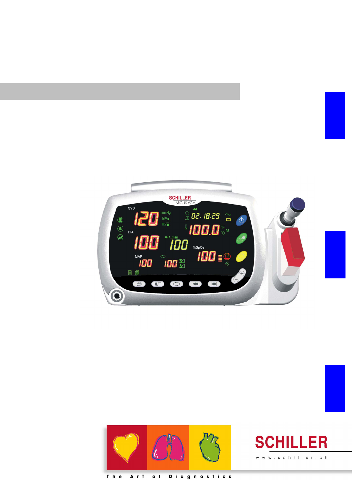
ARGUS VCM
English Français
Vital Compact Monitor
Patientenmonitor
Moniteur patient
Deutsch
Art. No.: 2.510558 Rev. a *2.510558*
User Guide
Gebrauchsanweisung
Mode d'emploi
Page 2

Sales and Service information
The SCHILLER sales and service centre network is worldwide. For the
address of your local distributor, contact your nearest SCHILLER subsidiary. In case of difficulty a complete list of all distributors and subsidiaries
is provided on our internet site: http://www.schiller.ch
Sales information can also be obtained from:
Sales@schiller.ch
Argus VCM produced by
Mediana Co.,Ltd.
Verkaufs und Service Informationen
SCHILLER besitzt ein weltweites Netz von Kundendienst-, Verkaufs- und Beratungsstellen. Fragen Sie bei der nächsten SCHILLER-Niederlassung nach Ihrer lokalen Vertretung. Eine vollständige Liste aller Vertreter und Niederlassungen finden Sie auf unserer
Internet-Site: http://www.schiller.ch
Verkaufsinformationen erhalten Sie ausserdem unter: Sales@schiller.ch
Argus VCM produziert durch
Mediana Co.,Ltd.
Informations concernant la distribution et l’entretien
SCHILLER entretient un réseau international composé de services clients, de
services commerciaux et d’agences de conseil. Pour obtenir les coordonnées de
votre représentant local, veuillez vous adresser à la filiale SCHILLER la plus proche de votre domicile. Vous trouverez une liste complète de tou(te)s les représentants et filiales sur notre site Internet. http://www.schiller.ch
Des informations commerciales sont également disponibles à l’adresse
suivante : sales@schiller.ch
Argus VCM produit par
Mediana Co.,Ltd.
Address Headquater
SCHILLER AG Phone: +41 (0)41 766 42 42
Algasse 68 Fax: +41 (0)41 761 08 80,
CH-6341 Baar, Switzerland e-mail: sales@schiller.ch
Web: www.schiller.ch
Article Number 2.510558 Rev. a
Issue Date: 2. July 2004
Headquarters : SC HILLE R AG , Altgasse 68, CH-634 1 Baar , Switz erland, Phone: +41 ( 0) 41 766 42 42 , Fa x: +41 (0) 41 761 08 80, e-mail : sale
s@sch
iller.ch
Page 3

Contents
Figures
Tables
Notice
This document contains proprietary information that is protected by copyright. All Rights Reserved.
Reproduction, adaptation, or translation without prior written permission is prohibited, except as
allowed under the copyright laws.
Warranty
The information contained in this document is subject to change without notice.
Schiller makes no warranty of any kind with regard to this material, including, but not limited to, the
implied warranties or merchantability and fitness for a particular purpose.
Schiller shall not be liable for errors contained herein or for incidental or consequential damages in
connection with the furnishing, performance, or use of this material.
Revision History
The documentation part number and revision number indicate its current edition. The revision number
changes when a new edition is printed in accordance with the revision history of the documentation.
Minor corrections and updates which are incorporated at reprint do not cause the revision number to
change. The document part number changes when extensive technical changes are incorporated.
English
ARGUS VCM Operator’s Manual i
Page 4

Contents ARGUS VCM
Safety Information.................................................................................................................................... 1
General Safety Information............................................................................................................... 1
Warni ngs ..............................................................................................................................................1
Cautions............................................................................................................................................... 3
Introduction ...............................................................................................................................................5
Features for ARGUS VCM ................................................................................................................5
Intended Use for ARGUS VCM........................................................................................................ 6
About This Manual ............................................................................................................................6
Description of Controls, Indicators, Symbols and Displays............................................................ 7
Identification of Front Panel Controls and Symbols .....................................................................7
Identification of Rear Panel Components and Symbols ...............................................................8
Description of ARGUS VCM Symbols/Indicators .........................................................................9
Description of ARGUS VCM Controls ..........................................................................................13
Setting up the Monitor........................................................................................................................... 15
Unpacking and Inspection ..............................................................................................................16
List of Components.......................................................................................................................... 16
Power Cable Connections ...............................................................................................................17
Measurement Cable Connections ..................................................................................................18
Battery Operation.................................................................................................................................... 21
Operating ARGUS VCM on Battery Power.................................................................................. 21
Charging a Low Battery ..................................................................................................................22
Low Battery Indication.................................................................................................................... 22
Using the Monitor................................................................................................................................... 23
Turning on the Monitor ...................................................................................................................23
Performing Power On and Self-Test (POST)................................................................................. 24
Setting Date and Time .....................................................................................................................26
Setting Patient Type .........................................................................................................................27
Setting NIBP Units ...........................................................................................................................28
Setting Temperature Units and Modes..........................................................................................29
Setting Pulse Tone Volume..............................................................................................................30
Setting Alarm Volume ..................................................................................................................... 31
Resetting to Factory Defaults.......................................................................................................... 32
NIBP Monitoring .................................................................................................................................... 33
General............................................................................................................................................... 34
Setup Connections............................................................................................................................ 35
NIBP Measurement Modes............................................................................................................. 36
Description of NIBP Operation ......................................................................................................36
SpO2/Pulse Rate Monitoring................................................................................................................ 41
General............................................................................................................................................... 42
Setup Connections............................................................................................................................ 43
Description of Pulse Rate Operation .............................................................................................44
Description of SpO2 Operation...................................................................................................... 44
Temperature Monitoring .......................................................................................................................47
General............................................................................................................................................... 48
Setup Connections............................................................................................................................ 48
Temperature Measurement Modes................................................................................................ 49
Description of Temperature Operation .........................................................................................49
Alarms and Limits...................................................................................................................................55
General............................................................................................................................................... 55
ii ARGUS VCM Operator’s Manual
Page 5

ARGUS VCM Contents
Setting Alarm Limits........................................................................................................................56
Alarm Silence ....................................................................................................................................62
Reviewing Patient Data .........................................................................................................................63
General............................................................................................................................................... 63
Displaying Stored Patient Data ......................................................................................................63
Printing Stored Patient Data (Optional Printer Installed) ..........................................................65
Erasing Patient Data......................................................................................................................... 65
Printing .....................................................................................................................................................67
General............................................................................................................................................... 67
Selecting Manual or Stream Printing type.................................................................................... 67
Printing Patient Data (Manual Mode)........................................................................................... 68
Print Out Configuration.................................................................................................................. 69
RS-232 Interface....................................................................................................................................... 71
Overview ...........................................................................................................................................71
Cable Connection ............................................................................................................................. 71
Nurse Call Interface .........................................................................................................................72
Quick Guide to Operation.....................................................................................................................73
Maintenance............................................................................................................................................. 79
General............................................................................................................................................... 79
Returning ARGUS VCM and System Components ....................................................................79
Service ................................................................................................................................................79
Periodic Safety Checks .....................................................................................................................80
Cleaning............................................................................................................................................. 80
Battery maintenance......................................................................................................................... 80
Replacement of Printer Paper......................................................................................................... 81
Troubleshooting ......................................................................................................................................83
General............................................................................................................................................... 83
Corrective Action.............................................................................................................................. 84
EMI (Electromagnetic Interference)............................................................................................... 85
Obtaining Technical Assistance...................................................................................................... 86
Factory Defaults ......................................................................................................................................87
General............................................................................................................................................... 87
Parameter Ranges and Default Settings........................................................................................ 87
Specifications........................................................................................................................................... 89
Physical.............................................................................................................................................. 89
Electrical.............................................................................................................................................89
Environmental .................................................................................................................................. 89
Measurement Parameters................................................................................................................90
Compliance........................................................................................................................................ 92
Manufacturer’s Declaration ............................................................................................................93
Figures
Figure 1. Front Panel Controls and Symbols.................................................................................................................................... 7
Figure 2. Rear Panel Components and Symbols............................................................................................................................... 8
Figure 3. AC Power Connection..................................................................................................................................................... 17
Figure 4. NIBP Cable Connections................................................................................................................................................. 18
Figure 5. SpO2 Sensor/Cable Connections..................................................................................................................................... 18
Figure 6. Temperature Probe Connections...................................................................................................................................... 19
Figure 7. ARGUS VCM Power On Self Test ................................................................................................................................. 24
Figure 8. ARGUS VCM Normal Mode Before Measurement........................................................................................................ 25
Figure 9. Date and Time Setting .................................................................................................................................................... 26
English
ARGUS VCM Operator’s Manual iii
Page 6

Contents ARGUS VCM
Figure 10. Patient Type Setting...................................................................................................................................................... 27
Figure 11. NIBP Units Setting....................................................................................................................................................... 28
Figure 12. Temperature Units and Modes Setting ......................................................................................................................... 29
Figure 13. Pulse Tone Volume Setting............................................................................................................................................ 30
Figure 14. Alarm Volume Setting................................................................................................................................................... 31
Figure 15. Factory Defaults Setting ............................................................................................................................................... 32
Figure 16. NIBP Setup Connections .............................................................................................................................................. 35
Figure 17. Initial Inflation Pressure............................................................................................................................................... 36
Figure 18. Manual mode of NIBP operation................................................................................................................................... 37
Figure 19. Indication of Auto Mode Turn-Off................................................................................................................................37
Figure 20. Auto Mode Setting (i.e.) – 15 minute Period................................................................................................................ 38
Figure 21. Auto Mode of Measurement.......................................................................................................................................... 38
Figure 22. STAT Mode Setting....................................................................................................................................................... 39
Figure 23. SpO2 Setup Connections .............................................................................................................................................. 43
Figure 24. Pulse Rate Operation .................................................................................................................................................... 44
Figure 25. SpO2 Operation............................................................................................................................................................ 44
Figure 26. Temperature Setup Connections.................................................................................................................................... 48
Figure 27. Temperature – Predictive Mode..................................................................................................................................... 50
Figure 28. Temperature – Monitored Mode.................................................................................................................................... 53
Figure 29. Example display of over 43°C or under 26°C................................................................................................................ 53
Figure 30. Systolic High Alarm Limit Setting............................................................................................................................... 57
Figure 31. Systolic Low Alarm Limit Setting................................................................................................................................. 57
Figure 32. Diastolic High Alarm Limit Setting ............................................................................................................................. 58
Figure 33. Diastolic Low Alarm Limit Setting............................................................................................................................... 58
Figure 34. MAP High Alarm Limit Setting................................................................................................................................... 59
Figure 35. MAP Low Alarm Limit Setting.................................................................................................................................... 59
Figure 36. Pulse Rate High Alarm Limit Setting........................................................................................................................... 60
Figure 37. Pulse Rate Low Alarm Limit Setting............................................................................................................................ 60
Figure 38. SpO2 High Alarm Limit Setting................................................................................................................................... 61
Figure 39. SpO2 Low Alarm Limit Setting.................................................................................................................................... 61
Figure 40. Stored Patient Data Display ......................................................................................................................................... 64
Figure 41. Printing Type Setting.................................................................................................................................................... 67
Figure 42. Real-Time Printing........................................................................................................................................................ 69
Figure 43. Stored Data Printing (Batch Printing) ......................................................................................................................... 69
Figure 44. Stream Printing at Alarm Condition ............................................................................................................................ 70
Figure 45. System Information Printing ........................................................................................................................................ 70
Figure 46. RS-232 I/O connector ................................................................................................................................................... 71
Figure 47. Data Port Pin Layout.................................................................................................................................................... 71
Tab le s
Table 1. Display Symbols/Indicators................................................................................................................................................. 9
Table 2. ARGUS VCM Controls .................................................................................................................................................... 13
Table 3. Front Panel Indications in accordance with power operation............................................................................................ 21
Table 4 . Cuf f S ize ............................................................................................................................................................................ 35
Table 5. SpO2 Sensors .................................................................................................................................................................... 43
Table 6. Indication of Temperature Measurement Mode................................................................................................................. 49
Table 7. Alarm Indication............................................................................................................................................................... 55
Table 8. Range of Alarm Limits (Defaults) ..................................................................................................................................... 56
Table 9. RS-232 Serial Interface Connections................................................................................................................................. 71
Table 10. Error Codes...................................................................................................................................................................... 83
Table 11. Parameter Ranges and Factory Defaults ......................................................................................................................... 87
Table 12. Electromagnetic Emissions (IEC60601-1-2) ................................................................................................................... 93
Table 13. Electromagnetic Immunity (IEC60601-1-2) ................................................................................................................... 93
Table 14. Electromagnetic Immunity (IEC60601-1-2) ................................................................................................................... 94
Table 15. Recommended Separation Distances ............................................................................................................................... 95
Table 16. Cables (IEC60601-1-2) .................................................................................................................................................... 95
iv ARGUS VCM Operator’s Manual
Page 7

Safety Information
General Safety Information
This section contains important safety information related to general use of
vital signs monitor. Other important safety information appears throughout the manual in
sections that relate specifically to the precautionary information. Read all precautionary
Warnings
information.
this manual.
Important! Before use, carefully read this manual, accessory directions for use, all
precautionary information, and specifications.
Warnings are identified by the WARNING symbol shown above.
Warnings alert you to potential serious outcomes (death, injury, or adverse events) to the
patient or user.
WARNING: To avoid burns, the probe must remain in the probe holder when
turning
WARNING: In the USA, do not connect to an electrical outlet controlled by a wall
switch because the device may be accidentally turned off.
WARNING: Impending power loss, the monitor will automatically operate by
internal battery. If in doubt about the integrity of the AC power source, the monitor
must be operated from its internal battery.
WARNING: Do not disconnect a power cord before the system power completely
shuts down because monitor settings may be lost at this moment.
WARNING: As with any medical equipment, carefully route patient cabling to
reduce the possibility of patient entanglement or strangulation.
WARNING: ARGUS VCM is not defibrillator proof. It may remain attached to the
patient during defibrillation or while an electrosurgical unit is in use, but the
readings may be inaccurate during use and shortly thereafter.
WARNING: If the monitor occurs to be abnormal shutdown, the monitor’s settings
are back to the factory defaults.
WARNING: You must check the equipment prior to use and ensure its safe and
proper use.
WARNING: Explosion hazard. Do not use ARGUS VCM monitor in the presence of
flammable anesthetics or gases. Do not operate ARGUS VCM in a hyperbaric
chamber, in oxygen-enriched environments, or in any other potentially explosive
environment.
ARGUS VCM vital signs monitor will be referred to as ARGUS VCM throughout
ARGUS VCM monitor on or off.
ARGUS VCM
English
ARGUS VCM Operator’s Manual 1
Page 8

Safety Information ARGUS VCM
WARNING: Do not autoclave the monitor.
WARNING: Before use, carefully read sensor or probe directions for use, including
all warnings, cautions, and instructions.
WARNING: Do not use damaged cuffs, sensors and other cables. Do not immerse
cuffs, sensors and other cables completely in water, solvents, or cleaning solutions
because the connectors are not waterproof. Do not sterilize cuffs, sensors and other
cables by irradiation, steam, or ethylene oxide. Refer to each cleaning instructions in
the directions for use.
WARNING: If the battery shows any signs of damage, leakage, or cracking, it must be
replaced immediately, by a qualified service person, and only with a battery
approved by the manufacturer.
WARNING: The monitor
used in conjunction with clinical signs and symptoms.
be
WARNING: The measurement of ARGUS VCM vital signs monitor can be affected
by patient conditions, motions, sensors, environmental condition and electromagnetic
external condition.
WARNING: It is possible that any radio frequency transmitting equipment and other
sources of electrical noise such as cellular phones, due to close proximity or strength
of a source, may result in disruption of performance.
WARNING: To ensure patient safety, do not place the monitor in any position that
might cause it to fall on the patient.
WARNING: Disconnect ARGUS VCM and sensors during magnetic resonance
imaging (MRI) scanning. Use during MRI could cause burns or adversely affect the
MRI image or the monitor’s accuracy. Also, to avoid burns, remove the sensors from
the patient before conducting MRI.
WARNING: During prolonged and continuous SpO2 monitoring, check the sensor
site at least once every 4 hours. Inspect the patient’s skin integrity and circulation,
and relocate the sensor if necessary. Tissue damage can result from improper or
prolonged sensor attachment.
WARNING: Do not lift the monitor by a sensor cable or a power cord because the
cable could disconnect from the monitor, causing the monitor to drop on the patient.
WARNING: ARGUS VCM may not operate effectively on patients who are
experiencing convulsions or tremors.
is intended only as an adjunct in patient assessment. It must
2
ARGUS VCM Operator’s Manual
Page 9

Cautions Cautions
Safety Information
CAUTION: Alert you to exercise care necessary for the safe and effective use of ARGUS
VCM monitor. Inaccurate data may be measured if operated or stored at conditions outside
the stated ranges, or subjected to excessive shock or dropping.
CAUTION: Grounding reliability can only be achieved when equipment is connected to an
equivalent receptacle marked 'Hospital Only' or 'Hospital Grade'.
CAUTION: The accuracy of the monitor may degrade if the monitor is connected to
secondary I/O devices when the monitor is not connected to earth reference.
CAUTION: Never place fluids on the monitor. In case of fluid spilling on the monitor,
disconnect power cord, wipe clean immediately and have the monitor serviced to ensure
that no hazard exists.
CAUTION: The monitor may clearly appropriate error codes when outside of the
measurable range occur.
English
glish
ARGUS VCM Operator’s Manual 3
Page 10

Safety Information ARGUS VCM
This page is intentionally left blank.
4
ARGUS VCM Operator’s Manual
Page 11

Introduction
Features
Intended Use
About This Manual
WARNING: ARGUS VCM is intended only as an adjunct in patient assessment. It
must be used in conjunction with clinical signs and symptoms.
This manual contains information about ARGUS VCM vital signs monitor. ARGUS VCM monitor includes
the following configuration:
Config. Features Config. Features
N Standard (NIBP + Pulse Rate) NP Standard + Printer
NS Standard + SpO2 NSP Standard + SpO2 + Printer
NT Standard + Temperature NTP Standard + Temperature+ Printer
NST Standard + SpO2 + Temperature NSTP Standard + SpO2 + Temperature + Printer
All information in this manual, including the illustrations, is based on a monitor configured with
the Temperature, SpO2, and Printer options. If your monitor configuration lacks any of these
options, then some information in this manual does not apply.
Features for ARGUS VCM
Physical
ARGUS VCM vital signs monitor is a lightweight and compact vital signs monitor measuring
130×180×278 (mm) (H×D×W) and weighing 2.7 kg. Its carrying handle is designed for
instrument transport while battery-powered monitoring.
Electrical
ARGUS VCM is powered by an internal battery pack that provides 2 hours of monitoring from
fully charged batteries (typical, performance is at 25 °C, with no printing and one NIBP
measurement every 15 minutes). The batteries are continuously recharged when AC power
(100-240 VAC, 50-60 Hz) is connected to the monitor. Details are described in the Battery
Operation section.
Display
ARGUS VCM has an FND display that shows numeric patient information as well as
alphanumeric status conditions and error codes.
Auxiliary
Outputs
ARGUS VCM monitor provides RS-232 I/O port for software upgrade or nurse call system.
Refer to the RS-232 Interface section for additional information.
English
ARGUS VCM Operator’s Manual 5
Page 12

Introduction ARGUS VCM
Intended Use for ARGUS VCM
The purpose and function of the Schiller
invasive blood pressure (systolic, diastolic, and mean arterial pressures), functional arterial
oxygen saturation, pulse rate and temperature for adult, pediatric and neonate patients in
all hospital areas and hospital-type facilities. It may be used during hospital transport and
in mobile, land-based environments, such as ambulances, within the specification of the
environmental characteristics.
Note: Hospital use typically covers such areas as general care floors, operating rooms,
special procedure areas, intensive and critical care areas, within the hospital plus
hospital-type facilities. Hospital-type facilities include physician office based facilities,
sleep labs, skilled nursing facilities, surgicenters, and sub-acutecenters.
Note: Intra-hospital transport includes transport of a patient within the hospital or hospital-
type facility.
ARGUS VCM vital signs monitor is to monitor non-
About This Manual
This manual explains how to set up and use
safety information relating to general use of
Other important safety information is located throughout the text where applicable.
All users should read this manual thoroughly. More experienced users of
be able to go to the topics for the information they require.
Read the entire manual including the Safety Information section, before you operate the
monitor.
ARGUS VCM vital signs monitor. Important
ARGUS VCM appears before this introduction.
ARGUS VCM will
6
ARGUS VCM Operator’s Manual
Page 13
Description of Controls, Indicators, Symbols and Displays
Identification of Front Panel Controls and Symbols
Identification of Rear Panel Controls and Symbols
Description of ARGUS VCM Symbols/ Indicators
Description of ARGUS VCM Controls
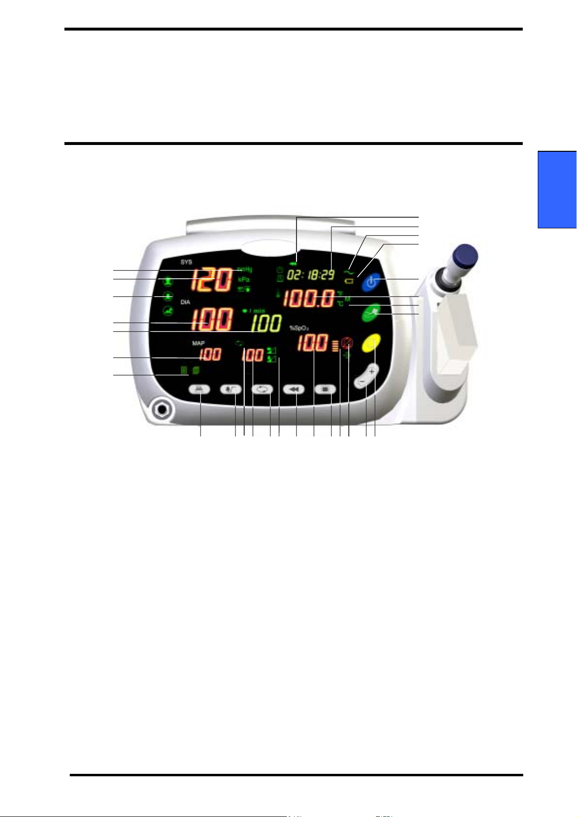
Identification of Front Panel Controls and Symbols Identification of Front Panel Controls and Symbols
1
2
3
4
5
6
28
27
26
25
2 4
23
22
21
English
glish
7
8 9 10 11 12 13 14 15 16 1718 19 20
1. Blood Pressure Unit Indicators 15. %SpO2 Display
2. Systolic Blood Pressure Display 16. Mode Button
3. Patient Type Indicators 17. Pulse Amplitude Indicator
4. Diastolic Blood Pressure Display 18. Alarm Silence Indicator
5. Pulse Rate Display 19. Up/Down Selection Button
6. MAP (Mean Arterial Pressure) Display 20. Alarm silence button
7. Print Setting Indicators 21. NIBP start/stop button
8. Print Button 22. Temperature Unit/Mode Indicators
9. Alarm Button 23. Temperature Display
10. Auto Indicator 24. Power Button
11. Auto Cycle Display 25. Battery Indicator
12. Auto Button 26. Charging/AC in Indicator
13. Pulse Tone/Alarm Volume Setting Indicators 27. Time Display
14. Review Button 28. Review Indicator
Figure 1. Front Panel Controls and Symbols
ARGUS VCM Operator’s Manual 7
Page 14
Description of Controls, Indicators, Symbols and Displays ARGUS VCM
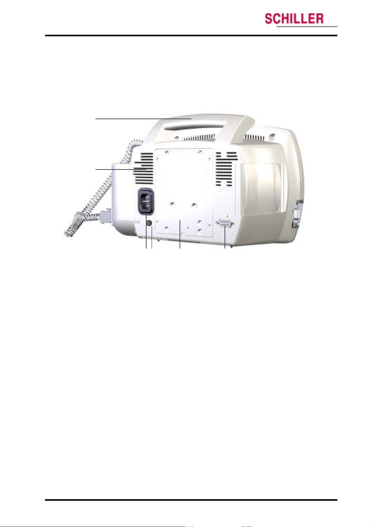
Identification of Rear Panel Components and Symbols
1
2
AC IN
100-240V~,
50/60 Hz
28-38VA
3 4 5 6
1. Handle 4. Equipotential (Ground)
2. Air Ventilator 5. Battery Cover (Replacement)
3. AC Power Connector 6. RS-232 Data Interface
Figure 2. Rear Panel Components and Symbols
8
ARGUS VCM Operator’s Manual
Page 15
ARGUS VCM Description of Controls, Indicators, Symbols and Displays
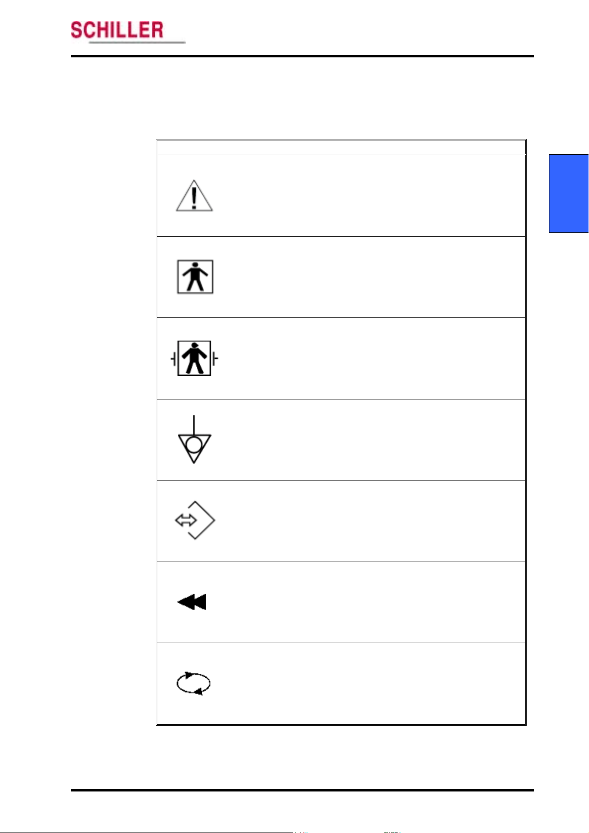
Description of ARGUS VCM Symbols/Indicators
The symbols and Indicators of
Symbols Description
ARGUS VCM are described as follows:
Table 1. Display Symbols/Indicators
Attention, consult accompanying documents.
Type BF applied part
English
Type BF – Defibrillator proof
Equipotientiality
Data interface
Review Indicator
is lit when the user select the Review button to see the patient
history.
Auto Indicator
is on whenever NIBP automatic timed cycles are enabled.
ARGUS VCM Operator’s Manual 9
Page 16
Description of Controls, Indicators, Symbols and Displays ARGUS VCM
Symbols Description
Charging/AC in Indicator
is on whenever AC power is present from the wall (even if the
monitor is off and is not under battery charging).
The Charging/AC in indicator flashes while the battery is
charging, and then remains illuminated once the battery is
maintained with a trickle charge.
Battery Indicator
indicates the state of the battery. This indicator is on when the
monitor uses battery power. This indicator will be flashing when
the battery needs charging. It is not reset unless AC power cord
has been plugged in for battery charging.
Alarm Silence Indicator
is on continuously whenever the unit is in Alarm Silence mode.
Temperature in degrees Fahrenheit
is configured to display temperature in degrees Fahrenheit.
Temperature in degrees Celsius
is configured to display temperature in degrees Celsius.
Temperature in Monitor mode
is configured to take temperature in the monitor mode. This
indicator is off when the temperature is being taken using the
predictive method.
Patient type: Adult
shall be on when the Patient type is adult.
10
Patient type: Pediatric
is on when the Patient type is pediatric.
ARGUS VCM Operator’s Manual
Page 17
ARGUS VCM Description of Controls, Indicators, Symbols and Displays
Symbols Description
Patient type: Neonatal
is on when the Patient type is neonatal.
NIBP unit: mmHg
is on when the NIBP unit setting is mmHg.
NIBP unit: kPa
is on when the NIBP unit setting is kPa.
English
Target Pressure Setting Indicator
is flashing when the NIBP target inflation pressure is under
setting for NIBP measurement.
Time Indicator
is on when the actual time is displayed on the time/date numeric
display area. It is flashing when it is selected to set the time in
the configuration mode.
Date Indicator
is on when the actual date is displayed on the time/date numeric
display area. It is flashing when it is selected to set the date in the
configuration mode.
Manual Print Indicator
is on when the print setting is the Manual Print.
Stream Print Indicator
is on when the print setting is the Stream Print.
ARGUS VCM Operator’s Manual 11
Page 18
Description of Controls, Indicators, Symbols and Displays ARGUS VCM
Symbols Description
Pulse Tone Volume Setting indicator
is flashing when the pulse tone volume setting is selected in the
setting mode.
Alarm Volume Setting Indicator
is flashing when the alarm volume setting is selected in the
setting mode.
Network Indicator
is flashing when the monitor is set to software upgrade mode.
12
ARGUS VCM Operator’s Manual
Page 19
ARGUS VCM Description of Controls, Indicators, Symbols and Displays
Description of ARGUS VCM Controls
Table 2. ARGUS VCM Controls
Controls Description
Power Button
ARGUS VCM monitor on or off when pressed
turns
for over 1 second.
NIBP start/stop button
initiates NIBP measurement when pressed. If the NIBP start/stop
button is pressed again during the measurement, it will cancel
the current reading.
Alarm Silence Button
allows you to silence a patient alarm temporarily and also is
used to acknowledge (cancel) other non-patient alarms.
Up/Down Selection Buttons
allows you to select items within a particular settable feature in
several different modes. If the Up or Down selection button is
pressed and held, the unit will scroll through the available
selections as if the button is being pressed repeatedly while the
button is held in.
English
Print Button (Option)
sends the data to the printer and prints current onscreen
readings if a printer is installed in the monitor. Pressing the Print
button during print-out stops printing.
Review Button
allows the user to review or to erase measurement data in the
memory. If pressed and held for more than 3 seconds, the
monitor will erase the data.
Auto Button
puts the monitor in Auto interval selection mode, allowing the
user to take automatic blood pressures at a selected increment.
ARGUS VCM Operator’s Manual 13
Page 20

Description of Controls, Indicators, Symbols and Displays ARGUS VCM
Controls Description
Alarm Button
puts the monitor into Alarm Set mode, allowing the user to set
alarm limits for Systolic, Diastolic, MAP, Pulse rate and SpO2.
Mode Button
puts the monitor into the Settings or Configuration mode. Once
the monitor is in one of these modes, the Mode button will be
used to cycle through the configuration options of the specific
menu mode.
14
ARGUS VCM Operator’s Manual
Page 21

Setting Up The Monitor
Unpacking and Inspection
List of Components
Power Cable Connections
Measurement Cable Connections
WARNING: ARGUS VCM is a prescription device and is to be operated by qualified
personnel only. ARGUS VCM is designed for use by medical clinicians. Although this
document might illustrate medical monitoring techniques, the monitor must be used
only by trained clinicians who know how to take and interpret a patient’s vital signs.
WARNING: In the USA, do not connect to an electrical outlet controlled by a wall
switch because the device may be accidentally turned off.
WARNING: As with all medical equipment, carefully route patient cabling to reduce
the possibility of patient entanglement or strangulation.
WARNING: To ensure patient safety, do not place the monitor in any position that
might cause it to fall on the patient.
WARNING: Do not lift the monitor by the sensor cables or power cord because the
cable could disconnect from the monitor, causing the monitor to drop on the patient.
WARNING: Disconnect ARGUS VCM and sensors/cables during magnetic resonance
imaging (MRI) scanning. Using the monitor during MRI may cause burns or adversely
affect the MRI image or the monitor’s accuracy.
WARNING: To ensure accurate performance or prevent device failure do not subject
ARGUS VCM to extreme moisture, such as direct exposure to rain. Such exposure may
cause inaccurate performance or device failure
WARNING: Do not use ARGUS VCM vital signs monitor, SpO2 sensors, temperature
probes or connectors that appear damaged.
WARNING: Discarded battery may explode during incineration. Follow local
government ordinances and recycle instructions regarding disposal or recycling of
device components, including batteries.
WARNING: ARGUS VCM is not defibrillator-proof. It may remain attached to the
patient during defibrillation or while an electrosurgical unit is in use, but the readings
may be inaccurate during the defibrillation and shortly thereafter.
WARNING: Ensure that the speaker is clear of any obstruction. Failure to do so could
result in an inaudible alarm tone.
CAUTION: If ARGUS VCM is to be stored for a period of 2 months or longer, it is
recommended to notify service personnel to remove the battery from the monitor prior to
storage. Recharging the battery is strongly recommended when the battery has not been
echarged for 2 or more months.
r
CAUTION: Recycle used batteries properly. Do not dispose of batteries in refuse containers.
English
glish
ARGUS VCM Operator’s Manual 15
Page 22

Setting up the Monitor ARGUS VCM
Unpacking and Inspection
ARGUS VCM vital signs monitor is shipped in one carton. Examine the carton carefully for
evidence of damage. Contact Schiller Technical Services Department immediately if any
damage is discovered. Return all packing material and monitor. Refer to the Maintenance
section for instructions on returning damaged items.
List of Components
Quantity Item
1
1 NIBP Cuff for adult (10.0 – 13.5 inch / 25.3 – 34.3 cm)
1 NIBP Cuff for pediatric (6.2 – 8.4 inch / 15.8 – 21.3 cm)
1 NIBP Hose for adult/pediatric
1 Temperature Probe with Temperature option configured
1 Temperature Probe Cover with Temperature option configured
1 SpO2 Sensor with SpO2 option configured
1 Pulse Oximetry Cable with SpO2 option configured
1
1 Power Cord (applicable to country of sale)
1 pack Printer Paper with Printer option configured
ARGUS VCM Vital signs monitor
ARGUS VCM Operator’s Manual
16
ARGUS VCM Operator’s Manual
Page 23
ARGUS VCM Setting up the Monitor
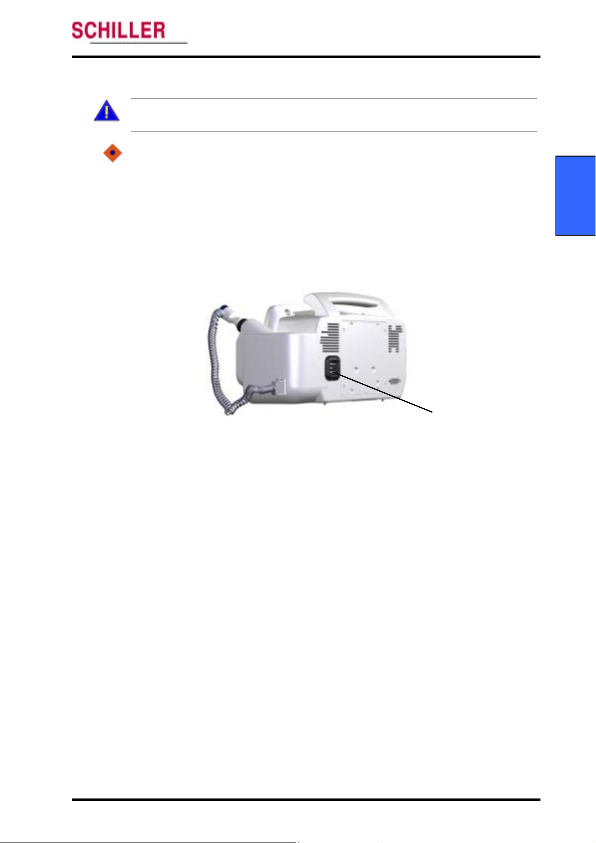
Power Cable Connections Power Cable Connections
WARNING: In the USA, do not connect to an electrical outlet controlled by a wall
switch because the device may be accidentally turned off.
CAUTION: For the safety of patients, use only a Schiller supplied power cord. Using an
unqualified power cord can damage the monitor, and will void the product warranty. If in
doubt about the integrity of the AC power source, the monitor must be operated from its
internal battery.
AC Power
Ensure that the AC outlet is properly grounded and that it is the specified voltage and
frequency (100-240 VAC, 50-60 Hz).
English
glish
1
AC Power Connector
Figure 3. AC Power Connection
1. Connect the female connector end of the AC power cord to the monitor rear panel
connector.
2. Plug the male connector end of the AC power cord into a properly grounded AC outlet.
3. Verify that the Charging/AC in Indicator is lit. This indicator will be flashing if the battery
needs charging.
Note: If the Charging/AC in Indicator is not lit, check:
the power cord
the AC power inlet
ARGUS VCM Operator’s Manual 17
Page 24
Setting up the Monitor ARGUS VCM
Measurement Cable Connections
WARNING: Do not lift the monitor by the sensor cables, or power cord because the
cable could disconnect from the monitor, causing the monitor to drop on the patient.
NIBP Hoses and Cuffs
NIBP Cuff Hose Connector
1. Select the appropriate size cuff for the patient (Refer to the NIBP Monitoring
section) and apply the cuff to the selected site.
2. Connect the hose to the right panel NIBP connector (see Figure 4).
Note: For the safety of patients, and to ensure the best product performance and accuracy,
use only a cuff and a hose provided with
by Schiller Technical Services.
SpO2 Cables and Sensors
1
Figure 4. NIBP Cable Connections
ARGUS VCM, or a cuff and hose recommended
Note: For the safety of patients, and to ensure the best product performance and accuracy,
18
1
SpO2 Sensor/ Cable Connector
Figure 5. SpO2 Sensor/Cable Connections
1. Select an appropriate sensor for the patient and desired application.
2. Apply the sensor to the selected site.
3. Connect the sensor to the cable.
4. Connect the cable to the right panel SpO2 connector (see Figure 5).
use only Schiller provided sensor pulse oximetry cables and SpO2 sensors with
VCM
.
ARGUS VCM Operator’s Manual
ARGUS
Page 25
ARGUS VCM Setting up the Monitor
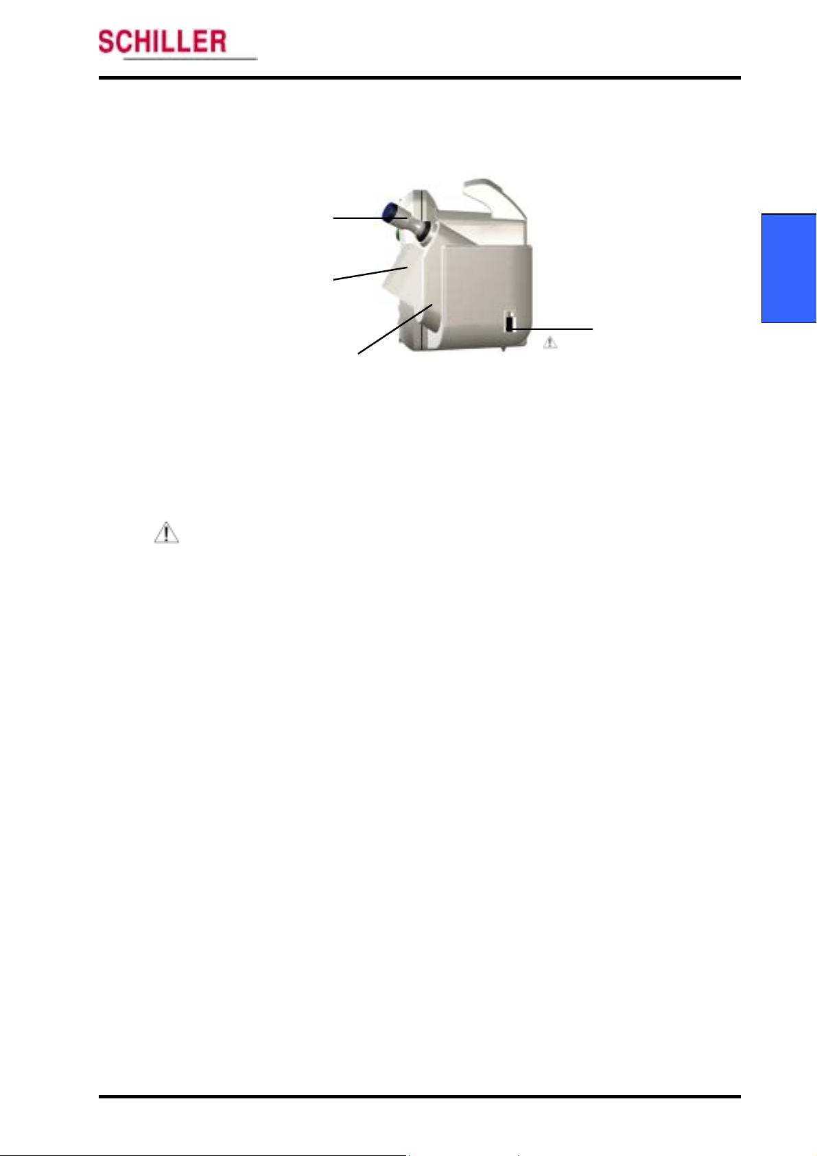
Temperature Probes Temperature Probes
1
Temperature Probe
English
2
Temperature Probe Cover
Temperature Probe Holder
3
4
Temperature Probe Connector
glish
Figure 6. Temperature Probe Connections
1. Insert the plug into the compatible jack on the monitor right panel.
Note: For the safety of patients, and to ensure the best product performance and accuracy,
use only Schiller provided temperature probes (see Figure 6).
Note: The temperature probes are available from Schiller sales department. For the safety of
patients, and to ensure the best product performance and accuracy, use only
temperature probes that have passed the recommended biocompatibility testing in
compliance with ISO10993-1.
ARGUS VCM Operator’s Manual 19
Page 26

Setting up the Monitor ARGUS VCM
This page is intentionally left blank.
20
ARGUS VCM Operator’s Manual
Page 27
Battery Operation
Operating ARGUS VCM on Battery Power
Charging a Low Battery
Low Battery Indication
WARNING: Dispose of Battery in accordance with local requirements and regulation.
Follow local government ordinances and recycle instructions regarding disposal or
recycling of batteries.
CAUTION: If ARGUS VCM is to be stored for a period of 2 months or longer, it is
recommended to notify service personnel to remove the battery from the monitor prior to
storage. Recharging the battery is strongly recommended when it has not been recharged
for 2 or more months.
CAUTION: Measured or displayed data may not be assured in the low battery or the
critical low battery condition.
CAUTION: Discarded battery may explode during incineration. Recycle used batteries
properly. Do not dispose of batteries in refuse containers.
Note: It is recommended that the monitor remain connected to AC power source when not
in use. This will ensure a fully charged battery whenever it is needed.
Note: As the battery is used and recharged over a period of time, the amount of time
between the onset of the low battery alarm and the instrument shut-off may become
shorter. It is recommended for service personnel to check periodically or replace of
internal battery if necessary.
Operating ARGUS VCM on Battery Power
ARGUS VCM monitor has an internal battery that can be used to power the monitor during
transport or when AC power source is not available.
Table 3. Front Panel Indications in accordance with power operation
English
glish
Condition
Monitor AC Power Battery
No operation Connected Full charged ‘Charging/AC in’ on
No operation Connected Charging ‘Charging/AC in’ flashing
Operation Connected Full charged ‘Charging/AC in’ on
Operation Connected Charging ‘Charging/AC in’ flashing
Operation Disconnected Normal battery status ‘Battery’ on
Operation Disconnected Low battery status ‘Battery’ flashing
ARGUS VCM
Operator’s Manual 21
Indicators
Page 28

Battery Operation ARGUS VCM
The monitor cannot operate with a fully discharged battery. Before turning on ARGUS VCM
which battery has been completely discharged, first plug the monitor into an AC outlet to
charge the battery for a few minutes. The monitor may then be powered on.
A new, fully charged battery will provide 2 hour of monitoring time under the following
conditions:
No audible alarms sound
No serial output devices are attached to
No printing
All the monitoring parameters are active with one NIBP measurement
per 15 minutes
ARGUS VCM
Charging a Low Battery
1. Connect the monitor to AC power in order to charge a low or dead battery.
(see the Setting up the Monitor section)
Note: A full charge of a dead battery takes approximately 12 hours while the monitor is
turned off.
Low Battery Indication
Battery Indicator is flashing when the remaining battery power is only enough for about 10
minutes of operation. The monitor will also sound an audible alarm. This will inhibit the
monitor from taking printing. This audible alarm can be silenced by pressing the Alarm
silence button. Connecting the monitor to AC power will terminate the alarm.
The monitor remaining the battery status of only about 3-minute operation will inhibit the
monitor from taking NIBP inflation.
After a critical low battery alarm sounds for about 5 seconds,
automatically shut down. You should connect the monitor to an AC power source to avoid
any loss of monitor settings and trend data
ARGUS VCM monitor will
22
ARGUS VCM Operator’s Manual
Page 29

Using The Monitor
Turning on the Monitor
Performing Power On and Self-Test (POST)
Setting Date and Time
Setting Patient Type
Setting NIBP Units
Setting Temperature Units and Modes
Setting Pulse Tone Volume
Setting Alarm Volume
Resetting to Factory Defaults
WARNING: To avoid burns, the probe must remain in the probe holder when turning
ARGUS VCM monitor on or off.
WARNING: If the POST (power on self-test) of ARGUS VCM is not completed
successfully, do not use the monitor.
WARNING: Ensure that the speaker is clear of any obstructions. Failure to do so could
result in an inaudible alarm tone.
WARNING: Disconnect ARGUS VCM and sensors/cables during magnetic resonance
imaging (MRI) scanning. Using the monitor during MRI may cause burns or adversely
affect the MRI image or the monitor’s accuracy.
WARNING: ARGUS VCM is intended only as an adjunct in patient assessment. It must be
used in conjunction with clinical signs and symptoms.
WARNING: ARGUS VCM is a prescription device and is to be operated by qualified
personnel only. ARGUS VCM is designed for use by medical clinicians. Although this
document might illustrate medical monitoring techniques, the monitor must be used
only by trained clinicians who know how to take and interpret a patient’s vital signs.
WARNING: Each time the monitor is used, check alarm limits to ensure that they are
appropriate for the patient being monitored.
Turning on the Monitor
Before using
safe to use. Proper working condition will be verified each time
as described in the following procedure.
Note: Physiological conditions, medical procedures, or external agents that may interfere
with the monitor’s ability to detect and display measurements, include
dysfunctional hemoglobin, arterial dyes, low perfusion, dark pigment, and
externally applied coloring agents such as nail polish, dye, or pigmented cream.
Note: The parameters may be set on an individual basis, by the clinician, and these
settings will remain in effect until
ARGUS VCM, you must verify that the monitor is working properly and is
English
ARGUS VCM is turned on
ARGUS VCM is turned off.
ARGUS VCM
Operator’s Manual 23
Page 30
Using the Monitor ARGUS VCM
Performing Power On and Self-Test (POST)
CAUTION: ARGUS VCM automatically starts the Power-On-Self-Test, which tests the
monitor circuitry and functions. During POST (immediately after power-up), confirm
that all display segments and indicators are illuminated and the power on beep tone
sounds.
CAUTION: If any indicator or display element does not light, or the speaker does not
sound, do not use the monitor. Instead, contact qualified service personnel or Schiller
Technical Service Department.
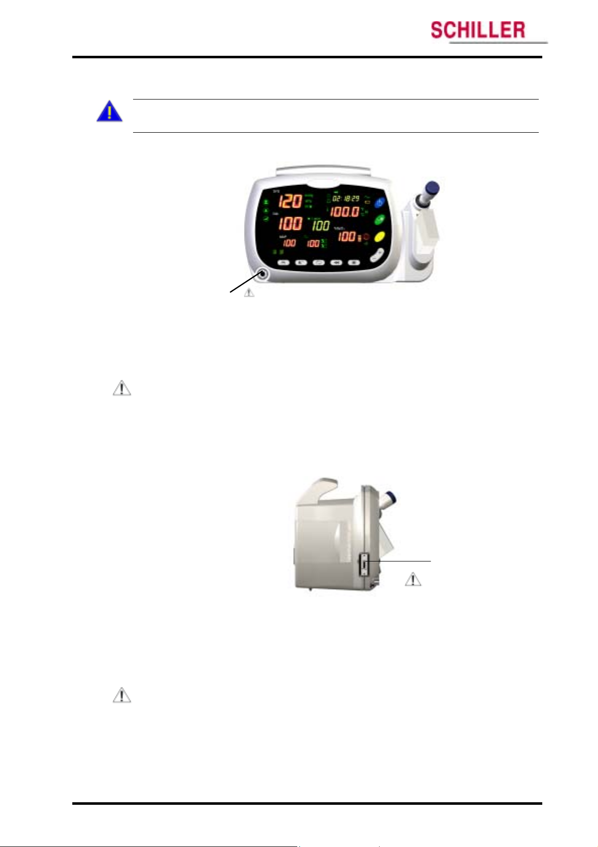
1. Turn on the monitor by pressing the Power button for over 1 second.
2. The monitor automatically starts the Power On Self Test (POST), which tests monitor
circuitry and functions.
3. Ensure the monitor sounds the power-on beep tones, and all displays and indicators
are illuminated for 3 seconds.
4. If
ARGUS VCM detects an internal problem during POST, the monitor will display an
error code. Contact qualified service personnel or Schiller Technical Services
Department.
24
Figure 7. ARGUS VCM Power On Self Test
ARGUS VCM Operator’s Manual
Page 31

ARGUS VCM Using the Monitor
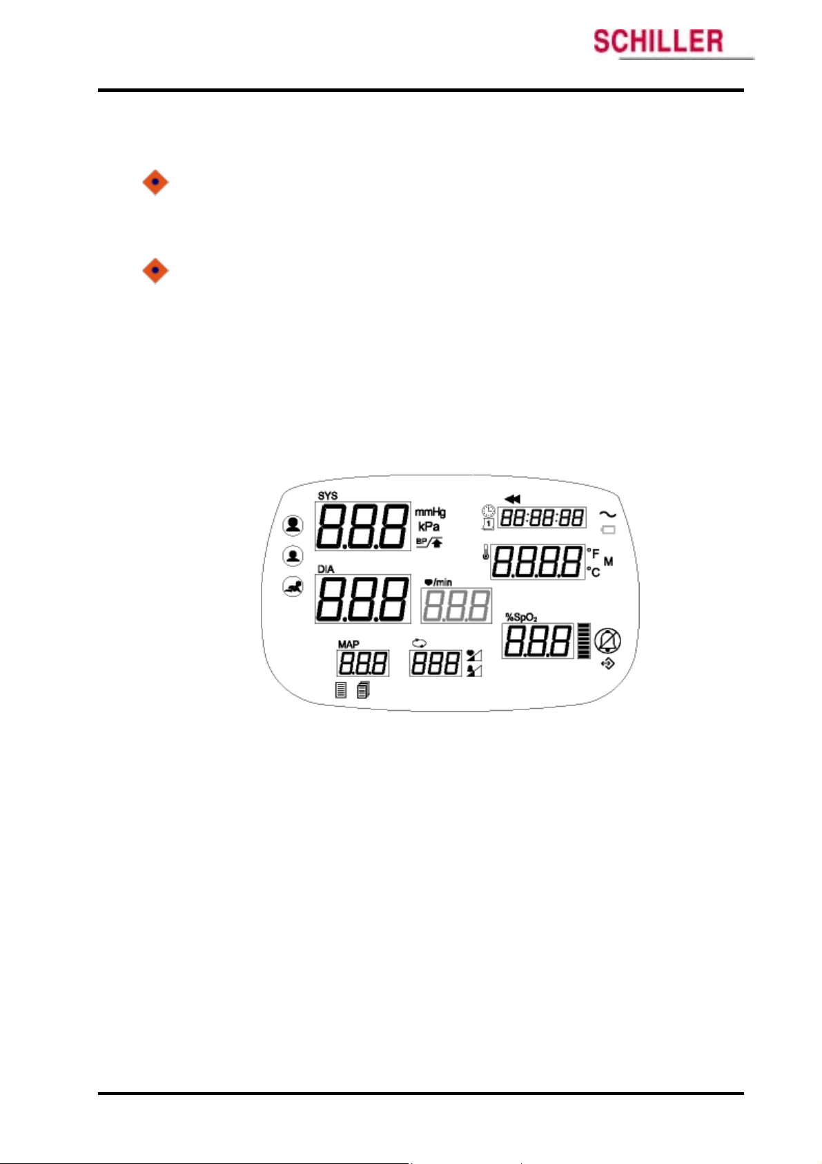
5. Upon successful completion of the POST, the monitor is blanked and enters Normal
mode.
English
Figure 8. ARGUS VCM Normal Mode Before Measurement
Note: If the segment of ‘SYS’, ‘DIA’ and ‘MAP’ displays is blinking, do not use the
monitor and contact qualified service personnel or Schiller Technical Services
Department because this symptom indicates that an internal problem may occur.
ARGUS VCM Operator’s Manual 25
Page 32

r
Using the Monitor ARGUS VCM
Setting Date and Time
This procedure will enable you to set current date and time of
With the monitor in the normal monitoring mode:
1. Press and hold the Mode button for 3 seconds or more until the monitor
enters Configuration mode.
2. Press the Mode button twice until the Time indicator and Hour set are
flashing.
Set current time to increment Hour up and down between 0 and 23, using the
Up/Down (+/-) selection buttons.
3. Press the Mode button until the Time indicator and Minute set are flashing.
Set current minute between 00 and 59, using the Up/Down (+/-) selection
buttons.
4. Press the Mode button until the Time indicator and Second set are flashing.
Set current second between 00 and 59, using the Up/Down (+/-) selection
buttons.
5. Press the Mode button until the Date indicator and Year set are flashing.
Set current year, using the Up/Down (+/-) selection buttons.
6. Press the Mode button until the Date indicator and Month set are flashing.
Set current month, using the Up/Down (+/-) selection buttons.
7. Press the Mode button until the Date indicator and Day set are flashing.
Set current day, using the Up/Down (+/-) selection buttons.
8. Pressing buttons other than the Mode button also returns to normal operation.
If there is no activity for 5 seconds, the monitor will return to normal
operation.
Figure 9. Date and Time Setting
ARGUS VCM monitor.
Hou
Minute
Second
Year
Month
Day
26
ARGUS VCM Operator’s Manual
Page 33

ARGUS VCM Using the Monitor
Setting Patient Type
Setting Patient Type
This procedure will allow you to select Patient Type: Adult, Pediatric or Neonatal of
This procedure will allow you to select Patient Type: Adult, Pediatric or Neonatal of
ARGUS VCM monitor.
ARGUS VCM monitor.
With the monitor in the normal monitoring mode: With the monitor in the normal monitoring mode:
1. Press the Mode button until the Patient type indicators are on (a selected
1. Press the Mode button until the Patient type indicators are on (a selected
2. Select a desired patient type, using the Up/Down (+/-) selection buttons. 2. Select a desired patient type, using the Up/Down (+/-) selection buttons.
3. Press any other button to return to normal operation. If there is no activity for
3. Press any other button to return to normal operation. If there is no activity for
Patient type indicator is shown flashing).
Patient type indicator is shown flashing).
3 seconds, the monitor will return to normal operation.
3 seconds, the monitor will return to normal operation.
English
glish
Figure 10. Patient Type Setting
ARGUS VCM Operator’s Manual 27
Page 34

Using the Monitor ARGUS VCM
Setting NIBP Units
This procedure will allow you to select a NIBP measurement unit either mmHg or kPa.
With the monitor in the normal monitoring mode:
1. Press and hold the Mode button for 3 seconds or more until the monitor enters
Configuration mode. Once the monitor is in the Configuration mode, current
NIBP unit is flashing on the display.
2. Select a NIBP unit either mmHg or kPa, using the Up/Down (+/-) selection
buttons.
3. Press any other button to return to normal operation. If there is no activity for
3 seconds, the monitor will return to normal operation.
28
Figure 11. NIBP Units Setting
ARGUS VCM Operator’s Manual
Page 35

ARGUS VCM Using the Monitor
Setting Temperature Units and Modes
Setting Temperature Units and Modes
This procedure will allow you to set temperature type and measurement units of
This procedure will allow you to set temperature type and measurement units of
VCM
VCM
with temperature option. You may select a temperature measurement unit either
with temperature option. You may select a temperature measurement unit either
Celsius (°C) or Fahrenheit (°F) to be displayed. Also you may select whether to use
Celsius (°C) or Fahrenheit (°F) to be displayed. Also you may select whether to use
Monitor mode or Predictive mode for taking temperatures. For more information, refer
Monitor mode or Predictive mode for taking temperatures. For more information, refer
to page 49 in Temperature Monitoring section of this manual.
to page 49 in Temperature Monitoring section of this manual.
With the monitor in the normal monitoring mode: With the monitor in the normal monitoring mode:
1. Press the Mode button 3 times until the Temperature units and modes are on
1. Press the Mode button 3 times until the Temperature units and modes are on
(a selected unit/mode is shown flashing).
(a selected unit/mode is shown flashing).
2. Select desired temperature unit and mode, using the Up/Down (+/-) selection
2. Select desired temperature unit and mode, using the Up/Down (+/-) selection
buttons.
buttons.
Fahrenheit Predictive (F) Fahrenheit Monitored (F M)
Fahrenheit Predictive (F) Fahrenheit Monitored (F M)
Celsius Predictive (C) Celsius Monitored (C M)
Celsius Predictive (C) Celsius Monitored (C M)
3. Press any other button to return to normal operation. If there is no activity for
3. Press any other button to return to normal operation. If there is no activity for
3 seconds, the monitor will return to normal operation.
3 seconds, the monitor will return to normal operation.
ARGUS
ARGUS
English
glish
Figure 12. Temperature Units and Modes Setting
ARGUS VCM Operator’s Manual 29
Page 36

Using the Monitor ARGUS VCM
Setting Pulse Tone Volume
This procedure will enable you to set Pulse Tone Volume of
With the monitor in the normal monitoring mode:
1. Press the Mode button 4 times until the Pulse Tone Volume setting indicator
and current pulse tone volume are displayed.
2. Select a level of pulse tone volume between 0 and 8, using the Up/Down (+/-)
selection buttons.
3. Press any other button to return to normal operation. If there is no activity for
3 seconds, the monitor will return to normal operation.
ARGUS VCM monitor.
Figure 13. Pulse Tone Volume Setting
30
ARGUS VCM Operator’s Manual
Page 37

ARGUS VCM Using the Monitor
Setting Alarm Volume
This procedure will enable you to set audible Alarm Volume of
With the monitor in the normal monitoring mode:
1. Press the Mode button 5 times until the Alarm Volume setting indicator and
current alarm volume are displayed.
2. Select a level of alarm volume between 1 and 8, using the Up/Down (+/-)
selection buttons.
3. Press any other button to return to normal operation. If there is no activity for
3 seconds, the monitor will return to normal operation.
ARGUS VCM monitor.
English
Figure 14. Alarm Volume Setting
ARGUS VCM Operator’s Manual 31
Page 38

Using the Monitor ARGUS VCM
Resetting to Factory Defaults
Following procedure will allow you to reset the monitor operating parameters to the
factory default settings.
With the monitor powered off:
1. Simultaneously press the Power button and the NIBP start/stop button.
2. The monitor runs a self-test and then displays the current monitor software
version.
3. Press the Mode button 4 times until “ DEFAULT RESET=NO” is displayed.
4. To leave the settings unchanged, select ‘NO’ using only the Down (-) selection
button.
To reset the operating parameters to the factory default values, select ‘YES’
using only the Up (+) selection button. The monitor immediately resets to the
defaults and the confirmation tone sounds.
5. To return to normal operation, turn the monitor off; then restart.
32
Figure 15. Factory Defaults Setting
ARGUS VCM Operator’s Manual
Page 39

NIBP Monitoring
General
Setup Connections
NIBP Measurement Modes
Description of NIBP Operation
WARNINGS: For the safety of patients, and to ensure the best product performance
and accuracy, use only the Cuffs and the Hose or a hose provided with the monitor, or
cuff recommended by Schiller Technical Services. Using other cuffs or hoses may
result in inaccuracies.
WARNING: Inaccurate measurements may be caused by incorrect cuff application or
use, such as placing the cuff too loosely on the patient, using the incorrect cuff size, or
not placing the cuff at the same level as the heart, leaky cuff or hose, and excessive
patient motion.
WARNING: Keep patients under close surveillance when monitoring. It is possible,
although unlikely, that radiated electromagnetic signals from sources external to the
patient and ARGUS VCM can cause inaccurate measurement readings. Do not rely
entirely on ARGUS VCM readings for patient assessment.
WARNING: ARGUS VCM is not intended for diagnostic treatment. To ensure patient
safety, use other diagnosis equipments.
WARNING: ARGUS VCM displays results of the last blood pressure measurement
until another measurement starts. If a patient’s condition changes during the time
interval between measurements, ARGUS VCM will not detect the change or indicate
an alarm condition.
WARNING: Any excessive patient motion may cause inaccurate measurements of noninvasive blood pressure. Make sure there is no patient motion affected to blood
pressure measurements.
WARNING: The blood pressure cuff should not be applied to the same extremity as
the one to which an SpO2 sensor is attached, since cuff inflation will disrupt SpO2
monitoring and lead to nuisance alarms.
WARNING: Check the patient’s limb on which the cuff is applied to assure that
circulation is not constricted. Constriction of circulation is indicated by discoloration
of the extremity. This check should be performed at the clinician’s discretion at regular
intervals based on the circumstances of the specific situation.
WARNING: In some cases, rapid, prolonged cycling of an oscillometric, noninvasive
blood pressure monitor cuff has been associated with any or all of the following:
ischemia, purpura, or neuropathy. Apply the oscillometric cuff appropriately,
according to instructions, and check the cuff site and cuffed extremity regularly when
blood pressure is measured at frequent intervals or over extended periods of time.
WARNING: Never place the cuff on extremity being used for intravenous infusion or
any area where circulation is compromised or has the potential to be compromised.
Never fit NIBP system with Luer Lock adapters.
English
ARGUS VCM
Operator’s Manual 33
Page 40

NIBP Monitoring ARGUS VCM
WARNING: As with all automatically inflatable blood pressure devices, continual
cuff measurements can cause injury to the patient being monitored. Weigh the
advantages of frequent measurement and/or use of STAT mode against the risk of
injury.
WARNING: During use on patients, ensure that heavy objects are not placed on the
hose. Avoid crimping or undue bending, twisting, or entanglement of the hose.
WARNING: Never use an adult or pediatric monitor setting or cuff for an NIBP
measurement on a neonatal patient. Adult and pediatric inflation limits can be
excessive for neonatal patients, even if a neonatal cuff is used.
WARNING: NIBP readings may be inaccurate for patients experiencing moderate to
severe arrhythmia.
Note: A patient’s vital signs may vary dramatically during administration of agents
affecting the cardiovascular system, such as those used to raise or lower blood
pressure or raise or lower heart rate.
Note: Blood pressure measurements can be affected by the position of the patient, the
patient’s physiological condition, and other factors.
General
NIBP processing by the monitor uses the oscillometric measuring technique. A motorized
pump inflates the cuff to initially blocking the flow of blood in the extremity. Then, under
monitor control, the pressure in the cuff is gradually reduced, while a pressure transducer
detects air pressure and transmits a signal to the NIBP circuitry.
When the cuff pressure is still above systolic pressure, small pulses or oscillations in the cuff
pressure begin to be sensed by the transducer. As the cuff continues to deflate, oscillation
amplitude increases to a maximum and then decreases. When maximum oscillation
amplitude occurs, the cuff pressure at that time is measured as mean arterial pressure
(MAP). The systolic and diastolic pressures are calculated based on analysis of the
oscillation amplitude profile.
34
ARGUS VCM Operator’s Manual
Page 41

ARGUS VCM NIBP Monitoring
Setup Connections Setup Connections
NIBP Cuff Hose Connector
1
Figure 16. NIBP Setup Connections
For the safety of patients, and to ensure the best product performance and accuracy, use only
the cuffs and the hose provided with
Services.
1. Measure the patient’s limb and select the proper size cuff. As a general rule, cuff width
should span approximately two-thirds of the distance between the patient’s elbow and
shoulder. Follow cuff directions for use for applying the cuff to the arm.
2. Connect the hose to the bottom of left corner of the monitor as shown Figure 16.
ARGUS VCM or recommended by Schiller Technical
English
glish
Table 4. Cuff Size
Cuffs Circumference Range
Newborn (arm), disposable/durable 3.0 – 4.1 (inch) / 7.7 – 10.5 (cm)
Infant (arm), disposable/durable 3.9 – 5.2 (inch) / 9.8 – 13.3 (cm)
Pediatric (arm), disposable/durable 6.2 – 8.4 (inch) / 15.8 – 21.3 (cm)
Adult (arm), disposable/durable 10.0 – 13.5 (inch) / 25.3 – 34.3 (cm)
Large Adult (arm), disposable/durable 12.6 – 17.1 (inch) / 32.1 – 43.4 (cm)
ARGUS VCM Operator’s Manual 35
Page 42

NIBP Monitoring ARGUS VCM
NIBP Measurement Modes
Blood pressure measurements can be made in three modes:
MANUAL mode One measurement of each systolic/diastolic/mean arterial pressure.
Automatic (AUTO) mode Measurements at preset intervals.
STAT mode As many measurements as possible within a 5-minute period.
Description of NIBP Operation
Setting Initial Inflation Pressure
With the monitor in the normal monitoring mode:
1. Press the Mode button twice until current NIBP target inflation is displayed.
2. Change NIBP target inflation to be desired, using the Up/Down (+/-) selection buttons.
3. Press any other button to return to normal operation. If there is no activity for 3 seconds,
the monitor will return to normal operation.
The numeric display in the lower right corner of the NIBP frame indicates the setting of the
initial inflation pressure. The initial inflation pressure can be set from 100 to 270 mmHg for
adult (80 to 170 mmHg for pediatric, 50 to 132 mmHg for neonatal), in intervals of 10, 12, 20
or 30mmHg. You may select an initial cuff inflation pressure. This is particularly important
with children, since an initial cuff inflation pressure of factory default, 160 mmHg for adult
(120 mmHg for pediatric, 90 mmHg for neonatal) may be uncomfortable, and is typically
higher than it needs to be.
36
Figure 17. Initial Inflation Pressure
ARGUS VCM Operator’s Manual
Page 43

ARGUS VCM NIBP Monitoring
Initiating MANUAL mode of NIBP operation Initiating MANUAL mode of NIBP operation
1. Press, momentarily, the NIBP start/stop button. 1. Press, momentarily, the NIBP start/stop button.
A single blood pressure measurement will be made. As soon as an NIBP measurement
A single blood pressure measurement will be made. As soon as an NIBP measurement
begins, the SYS display dynamically shows the current cuff pressure.
begins, the SYS display dynamically shows the current cuff pressure.
Systolic, diastolic, and MAP values are presented when the measurement is completed. The
Systolic, diastolic, and MAP values are presented when the measurement is completed. The
measurements remain in the numeric display for 2 minutes or until another NIBP cycle
measurements remain in the numeric display for 2 minutes or until another NIBP cycle
begins.
begins.
Systolic
Diastolic
MAP
English
glish
Figure 18. Manual mode of NIBP operation
Initiating AUTO mode of NIBP operation
1. Press the Auto button. The latest selected interval is displayed.
2. .Press the Up/Down (+/- ) selection buttons to cycle through the options, which
include (- ), STAT, and a range of intervals: 1, 2, 3, 4, 5, 10, 15, 30, 45, 60, 90, 120, and
240 minutes for taking automatic blood pressures. The dash (-) indicate that automatic
measurement is turned off.
Figure 19. Indication of Auto Mode Turn-Off
Upon selection, automatic measurement is activated and the initial measurement will be
made immediately after you select an interval.
ARGUS VCM Operator’s Manual 37
Page 44

NIBP Monitoring ARGUS VCM
The AUTO indicator is flashing when s selected for the automatic mode interval. After the
first cycle, the cuff target pressure is not used; rather, the cuff inflates to a pressure level
20~30 mmHg above the previous systolic reading.
The automatic NIBP cycles continue until one of the following occurs:
The monitor reaches the 5-minute limit for a STAT measurement.
The monitor halts because the NIBP start/stop button is pressed.
The monitor halts because the Auto button is pressed.
The monitor halts because of an alarm, alert, or error condition.
The AUTO cycle is changed to ‘-’.
Note: During Auto mode, if an NIBP limit violation alarm occurs, this alarm disables any
automatic NIBP measurement until the alarm is released.
Figure 20. Auto Mode Setting (i.e.) – 15 minute Period
Note: The interval is the time from the beginning of one measurement cycle to the beginning
of the next measurement cycle.
Note: The selected interval is displayed on the Auto cycle display. The countdown timer for
initiating next measurement is displayed on the Time display.
38
Figure 21. Auto Mode of Measurement
ARGUS VCM Operator’s Manual
Page 45

ARGUS VCM NIBP Monitoring
Initiating STAT mode of NIBP operation
1. Press the Auto button. The latest selected interval is displayed.
2. Press the Up/Down (+/-) selection buttons to set STAT.
Upon selection, automatic measurement is activated and the initial measurement will
be made in 3 seconds after you select an interval.
English
Figure 22. STAT Mode Setting
With the selected interval STAT, the monitor takes repeated NIBP measurements for 5
minutes. Current cuff pressures are not dynamically displayed during a STAT reading. The
measurement displays the NIBP reading from the previous cycle until the current cycle
finishes. (Before the first cycle finishes, the display appears blank.)
Note: During STAT mode, if an alarm, alert, or error condition occurs, the STAT
measurement will be terminated.
Stopping Blood Pressure Measurements
1. Press the NIBP start/stop button at any time that you wish to stop the current
measurement and deflate the cuff. If AUTO or Stat mode is underway, the mode
including interval time will be reset.
Note: During AUTO mode, pressing the NIBP start/stop button at the time before the next
auto measurement starts will cancel the AUTO mode and will be made a single blood
pressure measurement (MANUAL mode).
ARGUS VCM Operator’s Manual 39
Page 46

NIBP Monitoring ARGUS VCM
This page is intentionally left blank.
40
ARGUS VCM Operator’s Manual
Page 47

SpO2/Pulse Rate Monitoring
General
Setup Connections
Description of Pulse Rate Operation
Description of SpO
WARNING: Tissue damage can be caused by incorrect application or use of an SpO2
sensor, for example by wrapping the sensor too tightly or by applying supplemental
tape. Inspect the sensor site as directed in the sensor directions for use to ensure skin
integrity and correct positioning and adhesion of the sensor.
WARNING: Do not use damaged SpO2 sensors. Do not use an SpO2 sensor with
exposed optical components. Do not immerse sensor completely in water, solvents, or
cleaning solutions because the sensor and connectors are not waterproof. Do not
sterilize SpO2 sensors by irradiation, steam, or ethylene oxide. Refer to the cleaning
instructions in the directions for use for reusable SpO2 sensors.
WARNING: Pulse oximetry readings and pulse signal can be affected by certain
ambient environmental conditions, sensor application errors, and certain patient
conditions.
WARNING: The monitor
used in conjunction with clinical signs and symptoms.
WARNING: Inaccurate measurements may be caused by:
WARNING: Loss of pulse signal can occur in any of the following situations:
WARNING: Do not attach any cable to the sensor port (sensor connector) that is
intended for computer use.
incorrect sensor application or use
significant levels of dysfunctional hemoglobin
(such as carboxyhemoglobin or methemoglobin)
intravascular dyes such as indocyanine green or methylene blue
exposure to excessive illumination, such as surgical lamps (especially ones with
a xenon light source), bilirubin lamps, fluorescent lights, infrared heating
lamps, or direct sunlight
excessive patient movement
high-frequency electrosurgical interference and defibrillators
venous pulsations
placement of a sensor on an extremity with a blood pressure cuff, arterial
catheter, or intravascular line
the patient has hypotension, severe vasoconstriction, severe anemia, or
hypothermia
there is arterial occlusion proximal to the sensor the patient is in cardiac arrest
or is in shock
the sensor is too tight
there is excessive illumination from light sources such as a surgical lamp, a
bilirubin lamp, or sunlight
a blood pressure cuff is inflated on the same extremity as the one to which an
SpO2 sensor is attached
2 Operation
is intended only as an adjunct in patient assessment. It must be
English
ARGUS VCM Operator’s Manual 41
Page 48

SpO2/Pulse Rate Monitoring ARGUS VCM
CAUTION: The sensor disconnect error and associated alarm indicate the sensor is either
disconnected or the wiring is faulty. Check the sensor connection and, if necessary, replace
the sensor, pulse oximetry cable, or both.
CAUTION: Inaccurate readings could result if a sensor is used incorrectly. Before using a
sensor, carefully read and understand the sensor directions for use. Periodically check to see
the sensor remains properly positioned on the patient and that skin integrity is acceptable.
Refer to sensor directions for use.
CAUTION: To ensure the best product performance and accuracy, use only Schiller
provided SpO2 sensors for SpO2 measurements. Other SpO2 sensors may cause improper
ARGUS VCM performance.
General
ARGUS VCM uses pulse oximetry to measure functional oxygen saturation in the blood. Pulse
oximetry works by applying an OXIMAX sensor to a pulsating arteriolar vascular bed. SpO2
and Pulse rate is updated every second. The OXIMAX sensor contains a dual light source
and photodetector. Bone, tissue, pigmentation, and venous vessels normally absorb a
constant amount of light over time. The arteriolar bed normally pulsates and absorbs
variable amounts of light during the pulsations. The ratio of light absorbed is translated into
a measurement of functional oxygen saturation (SpO2). Because a measurement of SpO2 is
dependent upon light from the OXIMAX sensor, excessive ambient light can interfere with
this measurement.
42
ARGUS VCM Operator’s Manual
Page 49

ARGUS VCM SpO2/Pulse Rate Monitoring
Setup Connections Setup Connections
ARGUS VCM.
Use only provided sensor pulse oximetry cables and SpO2 sensors with
Use only provided sensor pulse oximetry cables and SpO2 sensors with
Biocompatibility testing has been conducted on sensors in compliance with ISO10993-1,
Biocompatibility testing has been conducted on sensors in compliance with ISO10993-1,
Biological Evaluation of Medical Devices, Part 1: Evaluation and Testing. The sensors have
Biological Evaluation of Medical Devices, Part 1: Evaluation and Testing. The sensors have
passed the recommended biocompatibility testing and are therefore in compliance with
passed the recommended biocompatibility testing and are therefore in compliance with
ISO10993-1.
ISO10993-1.
When selecting a sensor, consider patient’s weight and activity, adequacy of perfusion,
When selecting a sensor, consider patient’s weight and activity, adequacy of perfusion,
availability of sensor sites, need for sterility, and anticipated duration of monitoring. For
availability of sensor sites, need for sterility, and anticipated duration of monitoring. For
more information, refer to Table 5, or contact to Schiller sales department.
more information, refer to Table 5, or contact to Schiller sales department.
ARGUS VCM.
1
English
glish
SpO2 Sensor/ Cable Connector
Figure 23. SpO2 Setup Connections
1. Observe all warnings and cautions in the directions for use.
2. Carefully apply the sensor to the patient, as described in the sensor directions for use. The
sensor may be connected directly to the connector. Typically, however, it is more
convenient to connect the sensor to the monitor by using an SpO2 pulse oximetry cable.
Table 5. SpO2 Sensors
Sensor Model Patient Size
OXIMAX Durasensor ® Oxygen transducer
(Reusable, non-sterile)
OXIMAX oxygen transducer (Sterile, single-use only) MAX-N
OXIMAX oxygen transducer (Sterile, single-use only) MAX-A >30 kg
OXIMAX adhesive reflectance oxygen transducer MAX-FAST >40 kg
DS-100A >40 kg
<3 or >40 kg
ARGUS VCM Operator’s Manual 43
Page 50

SpO2/Pulse Rate Monitoring ARGUS VCM
Description of Pulse Rate Operation
The monitor displays the pulse rate during SpO2 measurements. It displays NIBP pulse
information only if no SpO2 reading is available.
During the measurement period, the pulse amplitude indicator rises and falls in rhythm
with the monitored pulse rate. The pulse amplitude indicator is a segmented display
showing the relative strength of the detected pulse. As the detected pulse becomes stronger,
more bars light with each pulse.
Pulse Rate
Figure 24. Pulse Rate Operation
Description of SpO2 Operation
SpO2 Operation
SpO2 &
Pulse Amplitude Indicator
Figure 25. SpO2 Operation
44
ARGUS VCM Operator’s Manual
Page 51

ARGUS VCM SpO2/Pulse Rate Monitoring
Functional versus Fractional Saturation Functional versus Fractional Saturation
This monitor measures functional saturation — oxygenated hemoglobin expressed as a
This monitor measures functional saturation — oxygenated hemoglobin expressed as a
percentage of the hemoglobin that can transport oxygen. It does not detect significant
percentage of the hemoglobin that can transport oxygen. It does not detect significant
amounts of dysfunctional hemoglobin, such as carboxyhemoglobin or methemoglobin. In
amounts of dysfunctional hemoglobin, such as carboxyhemoglobin or methemoglobin. In
contrast, hemoximeters such as the IL482 report fractional saturation — oxygenated
contrast, hemoximeters such as the IL482 report fractional saturation — oxygenated
hemoglobin expressed as a percentage of all measured hemoglobin, including measured
hemoglobin expressed as a percentage of all measured hemoglobin, including measured
dysfunctional hemoglobin. To compare functional saturation measurements to those from an
dysfunctional hemoglobin. To compare functional saturation measurements to those from an
instrument that measures fractional saturation, fractional measurements must be converted
instrument that measures fractional saturation, fractional measurements must be converted
as follows:
as follows:
functional saturation = fractional saturation functional saturation = fractional saturation
100 – (%carboxyhemoglobin + %methemoglobin) 100 – (%carboxyhemoglobin + %methemoglobin)
Measured versus Calculated Saturation Measured versus Calculated Saturation
When saturation is calculated from a blood gas partial pressure of oxygen (PO2), the
When saturation is calculated from a blood gas partial pressure of oxygen (PO2), the
calculated value may differ from the SpO2 measurement of the monitor. This usually occurs
calculated value may differ from the SpO2 measurement of the monitor. This usually occurs
because the calculated saturation was not appropriately corrected for the effects of variables
because the calculated saturation was not appropriately corrected for the effects of variables
that shift the relationship between PO2 and pH, temperature, the partial pressure of carbon
that shift the relationship between PO2 and pH, temperature, the partial pressure of carbon
dioxide (PCO2), 2, 3-DPG, and fetal hemoglobin.
dioxide (PCO2), 2, 3-DPG, and fetal hemoglobin.
Automatic Calibration Automatic Calibration
Because light absorption by hemoglobin is wavelength dependent and because the mean
Because light absorption by hemoglobin is wavelength dependent and because the mean
wavelength of LEDs varies, an oximeter must know the mean wavelength of the OXIMAX
wavelength of LEDs varies, an oximeter must know the mean wavelength of the OXIMAX
sensor’s red LED to accurately measure SpO2. The wavelength range of the light emitted are
sensor’s red LED to accurately measure SpO2. The wavelength range of the light emitted are
near 660 nm and 890 nm with the energy not exceeding 15 mW. During monitoring, the
near 660 nm and 890 nm with the energy not exceeding 15 mW. During monitoring, the
instrument’s software selects coefficients that are appropriate for the wavelength of that
instrument’s software selects coefficients that are appropriate for the wavelength of that
individual sensor’s red LED; these coefficients are then used to determine SpO2.
individual sensor’s red LED; these coefficients are then used to determine SpO2.
Additionally, to compensate for differences in tissue thickness, the light intensity of the
Additionally, to compensate for differences in tissue thickness, the light intensity of the
sensor’s LEDs is adjusted automatically.
sensor’s LEDs is adjusted automatically.
Adjusting Pulse Tone Volume from SpO2 signal Adjusting Pulse Tone Volume from SpO2 signal
For the setting the pulse tone volume, you may refer to page 30, of this manual. For the setting the pulse tone volume, you may refer to page 30, of this manual.
1. Press the Mode button 4 times until the Pulse Tone Volume setting indicator and
1. Press the Mode button 4 times until the Pulse Tone Volume setting indicator and
current pulse tone volume are displayed.
current pulse tone volume are displayed.
2. Select a level of pulse tone volume between 0 and 8, using the Up/Down (+/-)
2. Select a level of pulse tone volume between 0 and 8, using the Up/Down (+/-)
selection buttons.
selection buttons.
× 100
English
glish
ARGUS VCM Operator’s Manual 45
Page 52

SpO2/Pulse Rate Monitoring ARGUS VCM
This page is intentionally left blank.
46
ARGUS VCM Operator’s Manual
Page 53

Temperature Monitoring
General
Setup Connections
Temperature Measurement Modes
Description of Temperature Operation
WARNING: To avoid burns, the probe must remain in the probe holder when turning
ARGUS VCM monitor on or off.
WARNING: The monitor is intended only as an adjunct in patient assessment. It must
be used in conjunction with clinical signs and symptoms.
WARNING: To ensure patient safety and to obtain accurate and reliable temperature
results, read this section thoroughly before using the temperature instrument.
WARNING: To limit patient cross-contamination, use only manufacturer’s
recommended single-use disposable probe covers. The use of any other probe cover, or
the failure to use a probe cover, can endanger patients in the electrical risk point of
view and produce inaccurate temperature measurements.
WARNING: Never re-use a probe cover. Discard, without using it, any probe cover
that makes contact with any heat source (including hands and fingers) prior to use.
WARNING: Use of a probe at the wrong site produces inaccurate measurements and
can cause patient injury.
WARNING: Use extreme caution when taking rectal temperatures on children. Insert
the probe tip only 3/8-inch (~1 cm) to avoid risk of bowel perforation.
WARNING: The thermometer consists of high-quality precision parts. Protect it from
severe impact or shock. Do not use the thermometer if you notice any signs of damage
to the probe or the instrument.
WARNING: Do not use the temperature instrument for any purpose other than those
described in this document. Doing so will invalidate the product warranty.
WARNING: The probe must remain in steady contact with the sublingual pocket
throughout the measurement period; otherwise, the monitor fails to accurately predict
the temperature.
English
ARGUS VCM
Operator’s Manual 47
Page 54

Temperature Monitoring ARGUS VCM
General
This section applies if the monitor is configured with the temperature option.
Measurement of patient temperature is accomplished by processing the signal from a probe
containing a resistance element whose impedance is temperature dependent. These devices
are called thermistors. The signal from the probe is conditioned by the monitor input
circuitry, processed, and the measured values are shown in the numeric frame.
Setup Connections
WARNING: To limit patient cross-contamination, use only manufacturer’s
recommended single-use disposable probe covers. The use of any other probe cover, or
the failure to use a probe cover, can endanger patients in the electrical risk point of
view and produce inaccurate temperature measurements.
1
Temperature Probe Connector
Figure 26. Temperature Setup Connections
Follow the directions for use accompanying the temperature probe.
Note: Use only provided temperature probes which have passed the recommended
biocompatibility testing in compliance with ISO10993-1.
Note: If temperature probes are not readily available, contact Schiller sales department. To
avoid nuisance limit alarms, the probe should be affixed to the patient before
connecting to
ARGUS VCM right panel connector.
48
ARGUS VCM Operator’s Manual
Page 55

ARGUS VCM Temperature Monitoring
Temperature Measurement Modes
Temperature measurements can be made in two modes:
PREDICTIVE mode
is a one-time measurement that takes only a few seconds. It results in a single
temperature reading which is displayed at the end of the brief measurement period.
MONITORED mode
is a continuous measurement over an indefinite period. The current temperature
displayed dynamically throughout the measurement period.
Description of Temperature Operation
Setting the Temperature Measurement Mode
For the setting the Temperature measurement mode, you may refer to page 29, of this
manual.
1. Press the Mode button 3 times until the Temperature units and modes are on (a
selected unit/mode is shown flashing).
2. Select desired temperature unit and mode, using the Up/Down (+/-) selection
buttons.
Note: If there is no activity for 3 seconds, the monitor will return to normal operation.
Table 6. Indication of Temperature Measurement Mode
English
Indication Temperature Mode
Celsius Predictive
Celsius Monitored
Fahrenheit Predictive
Fahrenheit Monitored
ARGUS VCM Operator’s Manual 49
Page 56

Temperature Monitoring ARGUS VCM
Taking a Predictive Measurement
To take a predictive temperature (Celsius Predictive or Fahrenheit Predictive indicator shall
be on), follow these steps:
Note: Verify that the temperature measurement type is set to predictive. (Indicator ‘M’ is not
illuminated.)
Temperature
- Predictive Mode (i.e. Celsius)
Figure 27. Temperature – Predictive Mode
Oral Measurement
1. Remove the temperature probe from the probe holder. The temperature probe runs a
self-test, displaying ‘888.8’ for a few seconds. When it is ready for use, verify “OrL”
appears in the temperature display. If not, press the Up/Down (+/-) selection buttons
to select Oral or Axillary.
2. Put a new probe cover on the probe tip. Verify that the cover locks into position.
3. Insert the tip of the probe into the mouth—under the tongue and against a sublingual
pocket.
4. Hold the probe in place until the measurement is complete.
When the temperature prediction is complete (usually about 10 seconds later), the
monitor briefly sounds a tone and displays the temperature reading, which persists
for one minute.
Note: Use only a blue-capped probe for oral temperatures.
Note: The probe must remain in steady contact with the sublingual pocket throughout
the measurement period; otherwise, the monitor fails to accurately predict the
temperature.
Note: During the measurement period, the temperature window displays a “walking
box”—a box with the sides illuminated sequentially. When the measurement is
complete, the monitor sounds a tone and displays the measurement in the
temperature window.
5. Eject the probe cover by pressing the ejection button, and hygienically dispose of it.
6. Return the probe into the probe well.
If the monitor cannot make a predicted measurement, it takes a monitored temperature.
(See “Taking a Monitored Measurement” on page 53.)
Possible reasons for a failure to predict are the following:
The measured temperature is below 94.5°F (27.1°C) for one minute or
The ambient temperature is above 93°F (26.1°C) or
If a probe position error occurs during the temperature determination, the temperature
display alternates between the measured temperature and “P”.
The temperature measurement varies too much during the prediction period.
50
ARGUS VCM Operator’s Manual
Page 57

ARGUS VCM Temperature Monitoring
Axillary Measurement
1. Remove the temperature probe from the probe holder. The temperature probe runs a
self-test, displaying ‘888.8’ for a few seconds. When it is ready for use, verify “ALY”
appears in the temperature display. If not, press the Up/Down (+/-) selection buttons
to select Oral or Axillary.
2. Put a new probe cover on the probe tip. Verify that the cover locks into position.
Note: Use only a blue-capped probe for axillary temperatures.
Note: During the measurement period, the temperature window displays a “walking
box”—a box with the sides illuminated sequentially. When the measurement is
complete, the monitor sounds a tone and displays the measurement in the
temperature window.
Note: Be sure that nothing touches the probe tip before you place it in the axillary
measurement site. If the probe tip is moved after it first makes contact, the
measurement is unreliable.
3. Lift the patient’s arm to fully expose the axilla.
4. Place the probe tip as high as possible in the axilla, and then bring the patient’s arm
down to make maximum contact with the probe tip. Hold the patient’s arm in this
position, keeping the patient as still as possible, for the duration of the measurement.
When the temperature prediction is complete (usually about 10 seconds later), the
monitor briefly sounds a tone and displays the temperature reading, which persists
for one minute.
5. Eject the probe cover by pressing the ejection button, and hygienically dispose of it.
6. Return the probe into the probe well.
If the monitor cannot make a predicted measurement, it takes a monitored temperature.
(See “Taking a Monitored Measurement” on page 53.)
Possible reasons for a failure to predict are the following:
The measured temperature is below 94.5°F (27.1°C) for one minute or
The ambient temperature is above 93°F (26.1°C) or
The temperature measurement varies too much during the prediction period.
Be sure that the probe tip is fully covered by the axilla and the arm, and that it is not
touching any clothing.
If a probe position error occurs during the temperature determination, the temperature
display alternates between the measured temperature and “P”.
English
ARGUS VCM Operator’s Manual 51
Page 58

Temperature Monitoring ARGUS VCM
Rectal Measurement
1. Remove the temperature probe from the probe holder.
The temperature probe runs a self-test, displaying ‘888.8’ for a few seconds. When it is
ready for use, the monitor clears the temperature display. “rEC” appears in the
temperature display.
2. Load a probe cover onto the probe.
3. Apply a thin coat of water-based lubricant to the probe tip.
4. Separate the patient’s buttocks with one hand.
5. Insert the probe tip 1 centimeter (3/8-inch) inside the rectal sphincter. Tilt the probe
slightly to ensure good tissue contact, and keep the buttocks separated throughout the
duration of the measurement.
The monitor displays the temperature reading for one minute.
Note: Use only a red-capped probe for rectal temperatures.
Note: During the measurement period, the temperature window displays a “walking
box”—a box with the sides illuminated sequentially. When the measurement is
complete, the monitor sounds a tone and displays the measurement in the
temperature window.
6. Remove the probe.
7. Eject the probe cover by pressing the ejection button, and hygienically dispose of it.
8. Return the probe into the probe well.
If a probe position error occurs during the temperature determination, the temperature
display alternates between the measured temperature and “P”.
52
ARGUS VCM Operator’s Manual
Page 59

ARGUS VCM Temperature Monitoring
Taking a Monitored Measurement Taking a Monitored Measurement
To take a predictive temperature (Celsius Monitored or Fahrenheit Monitored indicator shall
To take a predictive temperature (Celsius Monitored or Fahrenheit Monitored indicator shall
be on), the procedures for monitored and predictive temperature measurements are the
be on), the procedures for monitored and predictive temperature measurements are the
same, with the following exceptions:
same, with the following exceptions:
For monitored measurements: For monitored measurements:
The monitor must be set to take a monitored temperature. The monitor must be set to take a monitored temperature.
The monitor displays the temperature continuously. The monitor displays the temperature continuously.
The measurement continues until the probe is replaced in the probe holder. The measurement continues until the probe is replaced in the probe holder.
Note: Verify that the temperature measurement type is set to monitored. Note: Verify that the temperature measurement type is set to monitored.
If the measured temperature remains below the minimum measurable temperature for 5
If the measured temperature remains below the minimum measurable temperature for 5
minutes, the temperature cycle is terminated and the temperature display goes blank. To
minutes, the temperature cycle is terminated and the temperature display goes blank. To
reactivate the probe, insert it into the probe holder and extract it again.
reactivate the probe, insert it into the probe holder and extract it again.
English
glish
Temperature
- Monitored mode (i.e. Celsius)
Figure 28. Temperature – Monitored Mode
Note: The monitor only displays 26°C to 43°C (80°F to 110°F). If the reading is over 43°C
(110°F) or under 26°C (80°F), the monitor will display as follows.
Figure 29. Example display of over 43°C or under 26°C
ARGUS VCM Operator’s Manual 53
Page 60

Temperature Monitoring ARGUS VCM
Probe Decontamination Procedure
1. Wipe the probe with a cloth dampened with warm water and a mild detergent
solution.
2. Clean the probe with either 70% isopropyl alcohol or a 10% solution of chlorine bleach.
3. Remove the probe from the probe well.
Unplug the latching probe connector from the thermometer.
Clean the inner surface of the probe well by swabbing with a cloth dampened
with 70% isopropyl alcohol or a 10% solution of chlorine bleach. You can
immerse the probe well during cleaning.
4. Thoroughly dry all surfaces.
5. Reassemble the thermometer components.
6. Reconnect the probe latching connector to the thermometer, making sure that the
connector snaps into place.
7. Reinstall the probe well into the monitor.
8. Insert the probe into the probe well.
Note: You can also replace any components of the thermometer. For the safety of patients,
and to ensure the best product performance and accuracy, use only parts recommended
by the manufacturer.
54
ARGUS VCM Operator’s Manual
Page 61

Alarms and Limits
General
Setting Alarm Limits
Alarm Silence
WARNING: Do not silence the audible alarm or decrease its volume if patient safety
could be compromised.
WARNING: Each time the monitor is used, check alarm limits to ensure that they are
appropriate for the patient being monitored.
WARNING: The audible and visual alarms on the monitor, used in conjunction with
clinical signs and symptoms, are the primary source for notifying medical personnel
that an alarm condition exists.
CAUTION: For patient safety, all alarms are reset to the factory default levels whenever
the patient type is changed. This means that you must either accept the default alarm
limits or set new limits every time you change patient type.
CAUTION: The high alarm limit for any vital sign is always higher than the low alarm
limit for the same vital sign. For example, the alarm limit for systolic high is always
higher than the alarm limit for systolic low.
Note: For adjusting alarm volume, you may refer to page 31, of this manual. Alarm
volume is set to ‘4’ as a factory default.
General
When the monitor detects certain conditions that require user attention, such as out-oflimit vital signs,
indicated by visual and audible indication
ARGUS VCM monitor enters an alarm state. The monitor response is
Table 7. Alarm Indication
English
glish
Alarm Condition Alarm Indication
Battery Failure
Loss of Pulse
Limit violation
Other system or
measurement error
Presenting appropriate error codes and sounding audible alarms.
Note: In case of loss of pulse alarm, error code (E44) is flashing
Flashing the violating value in the appropriate display and
sounding audible alarms.
Presenting appropriate error codes and sounding audible
alarms if available.
ARGUS VCM
Operator’s Manual 55
Page 62

Alarms and Limits ARGUS VCM
Setting Alarm Limits
During patient monitoring, an alarm occurs when a measurement falls outside the
programmed alarm limit. Alarms can be set or turned off for the following vital signs:
Systolic high and Systolic low alarm limits
Diastolic high and Diastolic low alarm limits
MAP high and MAP low alarm limits
Pulse rate high and Pulse rate low alarm limits
SpO 2 high and SpO 2 low alarm limits
The range of high and low alarm limits for each vital sign is shown here:
Table 8. Range of Alarm Limits (Defaults)
Parameter Low Limit, Default High Limit, Default Resolution
Systolic (mmHg)
Neonatal 25 to 115, 50 30 to 120, 100 5 mmHg (0.7 kPa)
Pediatric 30 to 155, 75 35 to 160, 145 5 mmHg (0.7 kPa)
Adult 30 to 255, 75 35 to 260, 220 5 mmHg (0.7 kPa)
Diastolic (mmHg)
Neonatal 10 to 100, 30 15 to 105, 70 5 mmHg (0.7 kPa)
Pediatric 15 to 125, 35 20 to 130, 100 5 mmHg (0.7 kPa)
Adult 20 to 250, 35 25 to 255, 110 5 mmHg (0.7 kPa)
MAP (mmHg)
Neonatal 10 to 105, 35 15 to 110, 80 5 mmHg (0.7 kPa)
Pediatric 15 to 135, 50 20 to 140, 110 5 mmHg (0.7 kPa)
Adult 20 to 250, 50 25 to 255, 120 5 mmHg (0.7 kPa)
PR (bpm)
Neonatal 25 to 295, 100 30 to 300, 200 5 bpm
Pediatric 25 to 295, 50 30 to 300, 150 5 bpm
Adult 25 to 295, 50 30 to 300, 120 5 bpm
SpO2 %
Neonatal 50 to 98, 85 52 to 100, 98 1%
Pediatric 50 to 98, 90 52 to 100, 100 1%
Adult 50 to 98, 90 52 to 100, 100 1%
56
ARGUS VCM Operator’s Manual
Page 63

ARGUS VCM Alarms and Limits
NIBP Alarm Limits
Alarm Limits determine the high and low points of patient data at which the monitor
will sound an alarm.
Systolic high and low alarm limits
With the monitor in the normal monitoring mode:
1. Press the Alarm button until Systolic high alarm limit is displayed.
2. Leave the limit unchanged or press the Up/Down (+/-) selection buttons as needed
to change the limit to another value.
3. Press the Alarm button once again until Systolic low alarm limit is displayed.
4. Leave the limit unchanged or press the Up/Down (+/-) selection buttons as needed
to change the limit to another value.
English
Figure 30. Systolic High Alarm Limit Setting
Figure 31. Systolic Low Alarm Limit Setting
ARGUS VCM Operator’s Manual 57
Page 64

Alarms and Limits ARGUS VCM
Diastolic high and low alarm limits
With the monitor in the normal monitoring mode:
1. Press the Alarm button 3 times until Diastolic high alarm limit is displayed.
2. Leave the limit unchanged or press the Up/Down (+/-) selection buttons as needed
to change the limit to another value.
3. Press the Alarm button once again until Diastolic low alarm limit is displayed.
4. Leave the limit unchanged or press the Up/Down (+/-) selection buttons as needed
to change the limit to another value.
Figure 32. Diastolic High Alarm Limit Setting
Figure 33. Diastolic Low Alarm Limit Setting
58
ARGUS VCM Operator’s Manual
Page 65

ARGUS VCM Alarms and Limits
MAP high and low alarm limits
With the monitor in the normal monitoring mode:
1. Press the Alarm button 5 times until MAP high alarm limit is displayed.
2. Leave the limit unchanged or press the Up/Down (+/-) selection buttons as needed
to change the limit to another value.
3. Press the Alarm button once again until MAP low alarm limit is displayed.
4. Leave the limit unchanged or press the Up/Down (+/-) selection buttons as needed
to change the limit to another value.
English
Figure 34. MAP High Alarm Limit Setting
Figure 35. MAP Low Alarm Limit Setting
ARGUS VCM Operator’s Manual 59
Page 66

Alarms and Limits ARGUS VCM
Pulse Rate Alarm Limits
Alarm Limits determine the high and low points of patient data at which the monitor
will sound an alarm.
With the monitor in the normal monitoring mode:
1. Press the Alarm button 7 times until Pulse rate high alarm limit is displayed.
2. Leave the limit unchanged or press the Up/Down (+/-) selection buttons as needed
to change the limit to another value.
3. Press the Alarm button once again until Pulse rate low alarm limit is displayed.
4. Leave the limit unchanged or press the Up/Down (+/-) selection buttons as needed
to change the limit to another value.
Figure 36. Pulse Rate High Alarm Limit Setting
Figure 37. Pulse Rate Low Alarm Limit Setting
60
ARGUS VCM Operator’s Manual
Page 67

ARGUS VCM Alarms and Limits
SpO2 Alarm Limits
Alarm Limits determine the high and low points of patient data at which the monitor
will sound an alarm.
With the monitor in the normal monitoring mode:
1. Press the Alarm button 9 times until SpO2 high alarm limit is displayed.
2. Leave the limit unchanged or press the Up/Down (+/-) selection buttons as needed
to change the limit to another value.
3. Press the Alarm button once again until SpO2 low alarm limit is displayed.
4. Leave the limit unchanged or press the Up/Down (+/-) selection buttons as needed
to change the limit to another value.
English
Figure 38. SpO2 High Alarm Limit Setting
Figure 39. SpO2 Low Alarm Limit Setting
ARGUS VCM Operator’s Manual 61
Page 68

Alarms and Limits ARGUS VCM
Alarm Silence
WARNING: Do not silence the audible alarm or decrease its volume if patient safety
could be compromised.
Press the Alarm Silence Button on the front panel. This action temporarily silences all
audible alarms for 90 seconds. Alarm Silence Indicator lights during a temporary silence
period.
1. Press the Alarm Silence Button to immediately silence the alarm tone. (Alarm
silence period default-90 seconds later, the alarm resumes if the alarm condition
has not been corrected.)
2. Check the patient and provide appropriate care.
If the Alarm Silence Button is pressed during the alarm silence, the alarm silence is
ended and the audible alarms are re-enabled.
Note: Visual indications of an alarm condition cannot be turned off. For example, if
the %SpO2 low alarm limit is exceeded, the audible alarm can be silenced for the
alarm silence period, but the %SpO2 value will continue to flash.
Note: Low Battery alarm cannot be silenced while running on battery power.
Connecting the monitor to AC power will silence the alarm. If a sensor disconnect
alarm is occurred, the alarm can be released by pressing the Alarm Silence Button.
Note: The alarms can be canceled by pressing the Alarm silence button, but battery
failure, loss of pulse and limit violation alarms cannot be released until the alarm
condition is terminated.
62
ARGUS VCM Operator’s Manual
Page 69

Reviewing Patient Data
General
Displaying Stored Patient Data
Printing Stored Patient Data (Optional Printer Installed)
Erasing Patient Data
General
You can review stored patient data either by viewing it on the monitor or by printing it. The
monitor stores 200 measurement data. After 200 data is reached, the oldest stored data will
be deleted for the newest data. 24-hour old data will also be automatically deleted. Data is
recorded when patient measurement completes or an alarm condition occurs.
Pressing the Review button while the monitor is in Normal mode or Auto mode will enter
Review mode. This will cause the monitor to display the most recent data set. If SpO2 data
or temperature data is available when the NIBP cycle completes, that information will be
included in the record and will display in Review mode.
Displaying Stored Patient Data
1. Press the Review button to display the newest stored set of patient vital-signs data.
The monitor interrupts the dynamic display of any current vital-sign
measurement.
The most current set of stored data including NIBP, SpO2, Pulse rate and
Temperature with a data-set sequence number and the time and date of the
displayed reading during a patient data review, if available, displays on entry
into Review mode.
The next most recent stored data sets display wrapping from the first stored
data set to the last by pressing the Review button subsequently.
In Review mode, the readings show time of reading in minus time, for
example, (-0:05) is 5 minutes ago, (-2:45) is 2 hour 45 minutes ago
2. Press the Up/Down (+/-) selection button to cycle forward or backward (scroll)
through the stored measurement data sets. (The monitor stores 200 measurement
cycles.)
3. To stop reviewing data and return to normal operation, press any button other than
the Review button or the Up/Down (+/-) selection button.
English
ARGUS VCM
Operator’s Manual 63
Page 70

Reviewing Patient Data ARGUS VCM
Data #1 Display: Data stored
at an error occurred 2 minutes ago
Data #2 Display: Data stored
at the measurement completed 18 minutes ago
Figure 40. Stored Patient Data Display
Note: 5 seconds of operator inactivity will exit Review mode and return to Normal mode.
64
ARGUS VCM Operator’s Manual
Page 71

ARGUS VCM Reviewing Patient Data
Printing Stored Patient Data (Optional Printer Installed)
You can print vital-signs measurement data each time the monitor completes a
measurement cycle (stream printing), or you can store patient data and then print all of it at
one time (batch printing). For information on setting the printer for stream printing or batch
printing, see “Printing section” on page 67.
Follow the instructions to print stored data if an optional printer is installed.
1. Press Print button when the monitor is in Review mode to display stored data on the
screen.
If the monitor is not printing, press the Print button to start printing.
If the monitor is printing, press the Print button to stop printing.
Note: The print button is not enabled during an NIBP cycle.
Erasing Patient Data
All patient vital-signs data is stored even the monitor is powered off, however 24-hour old
data will be removed. You can also erase patient data when you change the time and date
settings and at any time during normal monitor operation.
Erasing Data During Normal Operation
To erase patient data during normal operation;
1. Press and hold the Review button for 3 seconds to erase data in the memory. After
data cleared, the monitor returns to normal operation.
English
ARGUS VCM Operator’s Manual 65
Page 72

Reviewing Patient Data ARGUS VCM
This page is intentionally left blank.
66
ARGUS VCM Operator’s Manual
Page 73

Printing
General
Selecting Manual or Stream Printing Type
Printing Patient Data
Print Out Configuration
General General
This section applies if the monitor is configured with the printer option. This section applies if the monitor is configured with the printer option.
When the optional printer is installed, the monitor allows the user to print in Manual mode
When the optional printer is installed, the monitor allows the user to print in Manual mode
or Stream mode. The type is determined by the Print setting in Configuration mode.
or Stream mode. The type is determined by the Print setting in Configuration mode.
Manual Mode Manual Mode
The monitor prints out current measurement data (Real-time printing) or stored patient
The monitor prints out current measurement data (Real-time printing) or stored patient
data on the screen (Batch printing). Manual print indicator is on.
data on the screen (Batch printing). Manual print indicator is on.
Stream Mode Stream Mode
The monitor automatically prints out patient measurement data: as NIBP measurement or
The monitor automatically prints out patient measurement data: as NIBP measurement or
Temperature predictive measurement completes. Also in Stream mode, the monitor
Temperature predictive measurement completes. Also in Stream mode, the monitor
automatically prints out the measurement data when an alarm condition occurs. When the
automatically prints out the measurement data when an alarm condition occurs. When the
Print button is pressed at Stream mode, the monitor prints out current measurement data.
Print button is pressed at Stream mode, the monitor prints out current measurement data.
Stream print indicator is on.
Stream print indicator is on.
Selecting Manual or Stream Printing type Selecting Manual or Stream Printing type
This procedure will allow you to select Print mode either Manual or Stream. This procedure will allow you to select Print mode either Manual or Stream.
With the monitor in the normal monitoring mode: With the monitor in the normal monitoring mode:
1. Press and hold the Mode button for 3 seconds or more until the monitor enters
1. Press and hold the Mode button for 3 seconds or more until the monitor enters
Configuration mode.
Configuration mode.
2. Press the Mode button once again until either Manual Print or Stream Print
2. Press the Mode button once again until either Manual Print or Stream Print
indicator is flashing on the display.
indicator is flashing on the display.
3. Press the Up/Down (+/-) selection button to alternate between Manual Print and
3. Press the Up/Down (+/-) selection button to alternate between Manual Print and
Stream Print and display. A selected type indicator will be flashing on the display.
Stream Print and display. A selected type indicator will be flashing on the display.
4. To set the displayed printing method and return to normal operation, press any
4. To set the displayed printing method and return to normal operation, press any
other key. If there is no activity for 5 seconds, the monitor will return to normal
other key. If there is no activity for 5 seconds, the monitor will return to normal
operation.
operation.
English
glish
Figure 41. Printing Type Setting
ARGUS VCM
Operator’s Manual 67
Page 74

Printing ARGUS VCM
Printing Patient Data (Manual Mode)
You can print vital-signs measurement data each time you press the Print button (Manual
printing), or you can store patient data and then print all of it at one time (Batch printing).
Follow the instructions to print stored data if an optional printer is installed.
1. Press Print button when the monitor is in Normal or Review mode.
If the monitor is not printing, press the Print button to start printing.
If the monitor is printing, press the Print button to stop printing.
Note: The print button is not enabled during an NIBP cycle.
Note: The monitor sounds an invalid button tone when the printer door opens or when
paper runs out.
68
ARGUS VCM Operator’s Manual
Page 75

ARGUS VCM Printing
Print Out Configuration
Print Out includes information as follows:
Header: Time, Date, Measurement Parameters and Parameter units
Measurement data and/or error codes
Real Time Print Out at Manual and Stream Modes
Patient Name:
Patient ID:
Physician:
Comments:
TIME SYS DIA MAP HR O
- - mmHg - - BPM % °C
17:26 26-Mar-2004
17:26 127 84 98 68 98 36.1
2 TEMP
English
Stored Data Print Out
Figure 42. Real-Time Printing
Patient Name:
Patient ID:
Physician:
Comments:
TIME SYS DIA MAP HR O
- - mmHg - - BPM % °C
17:20 26-Mar-2004
17:19 126 83 98 60 98 36.5
17:15 123 82 97 62 98 36.5
17:14 E22 - - - - -
2 TEMP
Figure 43. Stored Data Printing (Batch Printing)
ARGUS VCM Operator’s Manual 69
Page 76

Printing ARGUS VCM
Stream Print Out at Alarm Condition
Patient Name:
Patient ID:
Physician:
Comments:
2 TEMP
26-Mar-2004
Adult
160
15
mmHg
Predict
°F
Manual
Off
4
4
220
75
110
35
120
50
120
50
100
90
6
2
1.00
2.00
1.81
2.1
System Information Print out
If the Print button is pressed while the monitor is in Service mode only accessed by
qualified authorized personnel, the monitor prints out the internal settings of the monitor as
shown in Figure 44.
TIME SYS DIA MAP HR O
- - mmHg - - BPM % °C
17:52 26-Mar-2004
17:52 127 84 98 200↑ 75 36.1
Figure 44. Stream Printing at Alarm Condition
17:52
Patient type:
NIBP target press (mmHg):
NIBP auto interval:
NIBP units:
Temperature mode:
Temperature units:
Print mode:
Night panel:
Pulse tone volume:
A larm tone volume:
Alarm limit settings
High Sys (mmHg)
Low Sys (mmHg)
High Dia (mmHg)
Low Dia (mmHg)
High MAP (mmHg)
Low MAP (mmHg)
High HR (BPM)
Low HR (BPM)
High SpO2 (%)
Low SpO2 (%)
Total cycles:
T otal runtime:
Software versions:
Units:
NIBP:
SpO2:
Temp:
70
Figure 45. System Information Printing
ARGUS VCM Operator’s Manual
Page 77

RS-232 Interface
Overview
Cable Connection
Nurse Call Interface
Overview Overview
ARGUS VCM monitor provides RS-232 I/O port for software upgrade or nurse call system.
ARGUS VCM monitor provides RS-232 I/O port for software upgrade or nurse call system.
The 9-pin connector mounted on the rear panel provides an access port for a serial interface.
The 9-pin connector mounted on the rear panel provides an access port for a serial interface.
RS-232 I/O port is intended only for connection to specified equipment in accordance with
RS-232 I/O port is intended only for connection to specified equipment in accordance with
compliance requirements.
compliance requirements.
Cable Connection Cable Connection
English
glish
Figure 46. RS-232 I/O connector
The Pin layouts (as viewed from the rear panel of
1
Figure 47. Data Port Pin Layout
Table 9. RS-232 Serial Interface Connections
Pin # Signal
1 +5V (Use for Software Upgrade)
2 RxD_232 (RS-232 Input)
3 TxD_232 (RS-232 Output)
4 DTR (Use for Software Upgrade)
5 Signal ground (Isolated from Earth ground)
6 DSR (Use for Software Upgrade)
7 Nurse call A
8 Nurse call B
9 SMODE (Use for Software Upgrade)
1
RS-232 I/O connector
ARGUS VCM) are illustrated below.
9876
5432
ARGUS VCM
Operator’s Manual 71
Page 78

RS-232 Interface ARGUS VCM
Nurse Call Interface
WARNING: Although the Nurse Call option enables remote notification of an alarm
condition, it is not intended to replace appropriate bedside patient surveillance by
trained clinicians.
The monitor can be connected to a Nurse Call system through a customized cable that
connects to the Nurse Call connector. When the cable is connected and operational, the
monitor immediately notifies the Nurse Call system when a patient alarm occurs.
The Nurse Call function specification is as follows:
Switch current: 1 A maximum
Switch voltage: 30 Vac/dc maximum
Isolation: 1500 Vrms
Alarm relay: Energized during patient alarm
72
ARGUS VCM Operator’s Manual
Page 79

Quick Guide to Operation
English
ARGUS VCM
Operator’s Manual 73
Page 80

Quick Guide to Operation ARGUS VCM
74
ARGUS VCM Operator’s Manual
Page 81

ARGUS VCM Quick Guide to Operation
English
ARGUS VCM Operator’s Manual 75
Page 82

Quick Guide to Operation ARGUS VCM
76
ARGUS VCM Operator’s Manual
Page 83

ARGUS VCM Quick Guide to Operation
English
ARGUS VCM Operator’s Manual 77
Page 84

Quick Guide to Operation ARGUS VCM
78
ARGUS VCM Operator’s Manual
Page 85

Maintenance
General
Returning ARGUS VCM and System Components
Service
Periodic Safety Checks
Cleaning
Battery Maintenance
Replacement of Printer Paper
WARNING: only qualified service personnel should remove the cover. There are no
internal user-serviceable parts.
WARNING: Do not spray, pour, or spill any liquid on ARGUS VCM vital signs
monitor, its accessories, connectors, switches, or openings in the chassis.
CAUTION: Unplug the power cord from the monitor before cleaning the monitor.
General
Follow local governing ordinance and recycling instructions regarding the disposal or
recycling of end of life use of
may be harmed from improper disposal of battery or accessories.
Returning ARGUS VCM and System Components
Contact Schiller Technical Services Department for shipping instructions including a
Returned Goods Authorization (RGA) number. Pack
sensors, cables or other accessory items in its original shipping carton. If the original carton
is not available, use a suitable carton with appropriate packing material to protect the
monitor during shipping. Return
of delivery.
Service
ARGUS VCM requires no routine service other than cleaning or battery maintenance that is
mandated by the user’s institution. For more information, refer to
manual. Qualified service personnel in the user’s institution should perform periodic
inspections of the monitor. If service is necessary, contact qualified service personnel or
Schiller Technical Services Department.
If the institution’s service personnel cannot correct problems,
returned to Schiller for service. Contact Schiller Technical Services Department for return
instructions.
ARGUS VCM and accessories. Otherwise environment or people
ARGUS VCM vital signs monitor with
ARGUS VCM by any shipping method that provides proof
ARGUS VCM service
ARGUS VCM should be
English
glish
ARGUS VCM Operator’s Manual 79
Page 86

Maintenance ARGUS VCM
Periodic Safety Checks
It is recommended that the following checks be performed every 24 months.
Inspect the equipment for mechanical and functional damage.
Inspect the safety relevant labels for legibility.
Cleaning
For surface-cleaning, follow your institution’s procedures or:
ARGUS VCM may be surface-cleaned by using a soft cloth dampened with either a
commercial or nonabrasive cleaner, and lightly wiping the top, bottom, and front
surfaces of the monitor lightly.
For sensors and probes follow cleaning, disinfecting and/or sterilizing instructions in the
directions for use shipped with those components.
Never allow any liquid substance to enter any monitor connector. If a connector does come
in contact with a liquid substance accidentally, clean and dry thoroughly before reuse. If in
doubt about monitor safety, refer the unit to qualified service personnel.
Battery maintenance
If
ARGUS VCM vital signs monitor has not been used 2 months, the battery will need charging.
To charge the battery, connect
Operation section.
Note: Storing
battery capacity. A full charge of a dead battery takes approximately 12 hours while
the monitor is turned off.
CAUTION: If ARGUS VCM is to be stored for a period of 2 months or longer, it is
recommended to notify service personnel to remove the battery from the monitor prior to
storage. Recharging the battery is strongly recommended when the battery has not been
recharged for 2 or more months.
CAUTION: If the battery shows any signs of damage, leakage, or cracking, it must be
replaced immediately, by a qualified service person, and only with a battery approved by
the manufacturer.
CAUTION: Discarded battery may explode during incineration. Follow local government
ordinances and recycle instructions regarding disposal or recycling of device components,
including batteries.
CAUTION: Recycle used batteries properly. Do not dispose of batteries in refuse containers.
ARGUS VCM for a long period without charging the battery may degrade the
ARGUS VCM to an AC power source as described in the Battery
80
ARGUS VCM Operator’s Manual
Page 87

ARGUS VCM Maintenance
Replacement of Printer Paper
The monitor provides the indication as follows:
The Manual Print indicator will flash in Manual mode.
The Stream Print indicator will flash in Stream mode.
1. Open the door by pulling the latch on the printer slightly. The door should tilt open.
2. Reach in and remove the spent paper core by pulling it over gently with your thumb
and index finger.
3. Place a new paper roll. Orient the paper roll.
4. Pull the paper towards you until approximately 2 inches (5.08 cm) of paper have been
unrolled.
5. Align the paper with the pinch roller attached to the printer door.
6. Close the printer door.
Note: To ensure that the paper is aligned in the slot and has not been pinched in the door,
pull the loose edge until a few inches of paper is showing. If the paper will not move,
open the door and return to alignment step 5.
Note: The monitor sounds an invalid button tone when the printer door opens or when
paper runs out.
English
ARGUS VCM Operator’s Manual 81
Page 88

Maintenance ARGUS VCM
This page is intentionally left blank.
82
ARGUS VCM Operator’s Manual
Page 89

Troubleshooting
General
Corrective Action
EMI (Electromagnetic Interference)
Obtaining Technical Assistance
WARNING: If you are uncertain about the accuracy of any measurement, check the
patient’s vital signs by alternate means; then make sure the monitor is functioning
correctly.
WARNING: only qualified service personnel should remove the cover. There are no
user-serviceable parts inside.
CAUTION: Do not spray, pour, or spill any liquid on ARGUS VCM, its accessories,
connectors, switches, or openings in the chassis.
General
If
ARGUS VCM is unable to perform any of its monitoring functions because of the loss of
software control a detected hardware malfunction, an error code is presented.
English
glish
Table 10. Error Codes
Error Codes Description
E01 Battery failure
E02 Abnormally shutdown last time
E09 System error (malfunction)
E21 Air leakage
E22 Cuff not detected
E23 Kinked or neonate hose
E24 Cuff too large for neonate
E25 Overpressure condition
E26 Motion artifact
E27 Weak pulse or no pulse detected
E28 Valid BP not found
E29 NIBP module error (malfunction)
E41 Sensor off
E42 Sensor disconnected
E43 Bad sensor
E44 Loss of pulse
E49 SpO2 module error (malfunction)
“P” Loss of tissue contact
E62 Probe disconnected
E63 Probe error
E64 Probe heated too high
E65 Ambient temperature out of range
E69 Temperature module error (malfunction)
ARGUS VCM
Operator’s Manual 83
Page 90

Troubleshooting ARGUS VCM
Serviceable error codes and other error codes are listed in ARGUS VCM service manual. If
the monitor continues to present an error code, call the Schiller technical representative and
report the error code number. You will be advised of the remedial action to be taken. Before
calling the Schiller Technical Services Department, make sure that the battery is charged,
and that all power connections are correctly made.
Corrective Action
If you experience a problem while using
qualified service personnel or Schiller Technical Services Department.
ARGUS VCM service manual, which is for user by qualified service personnel, provides
additional troubleshooting information.
Following is a list of possible errors and suggestions for correcting them.
1. There is no response to the Power On/Off switch.
A fuse may be blown. Notify service personnel to check and, if necessary, replace
the fuse.
If operating on battery power, the battery may be missing or discharged. If the
battery is discharged, charge the battery, see Battery Operation section.
2. The monitor display does not function properly and the power-on beep tones do not
sound during the power-on self-test.
Do not use
Services Department.
3. The monitor is operating on battery power, even though it is connected to AC.
Make sure that the power cord is properly connected to
Check to see if power is available to other equipment on the same AC circuit.
The monitor will be operated from its internal battery if in doubt about the integrity
of the AC power source,
ARGUS VCM; contact qualified service personnel or Schiller Technical
ARGUS VCM and are unable to correct it, contact
ARGUS VCM.
84
ARGUS VCM Operator’s Manual
Page 91

ARGUS VCM Troubleshooting
EMI (Electromagnetic Interference) EMI (Electromagnetic Interference)
WARNING: Keep patients under close surveillance when monitoring. It is possible,
although unlikely, that radiated electromagnetic signals from sources external to the
patient and ARGUS VCM can cause inaccurate measurement readings. Do not rely
entirely on ARGUS VCM readings for patient assessment.
WARNING: It is possible that any radio frequency transmitting equipment and other
sources of electrical noise such as cellular phones, due to close proximity or strength of
a source, may result in disruption of performance of ARGUS VCM.
WARNING: It is possible, although unlikely, that large equipment using a switching
relay for its power on/off may result in disruption of performance of ARGUS VCM
when the large equipment powers on or off. Do not place ARGUS VCM to monitor in
such environments.
CAUTION: This device has been tested and found to comply with the limits for medical
devices to the IEC60601-1-2, and the Medical Device Directive 93/42/EEC. These limits are
designed to provide reasonable protection against harmful interference in a typical medical
installation.
However, because of the proliferation of electromagnetic noise in health care environments
(for example; electrosurgical unit, cellular phones, mobile two-way radios, electrical
appliances, and high-definition television), it is possible that high levels of such interference
due to close proximity or strength of a source may result in disruption of performance of
this device.
CAUTION: ARGUS VCM is designed for use in environments in which the signal can be
obscured by electromagnetic interference. During such interference, measurements may
seem inappropriate or the monitor may not seem to operate correctly.
CAUTION: Disruption may be evidenced by erratic readings, cessation of operation, or
other incorrect functioning.
If this occurs, the site of use should be surveyed to determine the source of this disruption,
and the following actions taken to eliminate the source:
Turn equipment in the vicinity off and on to isolate the offending equipment.
Reorient or relocate the interfering equipment.
If assistance is required, contact Schiller Technical Services Department.
Increase the separation between the interfering equipment and this equipment.
English
glish
ARGUS VCM Operator’s Manual 85
Page 92

Troubleshooting ARGUS VCM
Obtaining Technical Assistance
For technical information and assistance, or to order an
Schiller Technical Services Department. The service manual includes information required
by qualified service personnel when servicing
When calling Schiller Technical Services Department, you may be asked to tell the
representative the software version number of your
or Schiller Technical Services Department may help you check the software version
installed in your monitor.
ARGUS VCM.
ARGUS VCM service manual, call
ARGUS VCM. Qualified service personnel
86
ARGUS VCM Operator’s Manual
Page 93

Factory Defaults
General
Parameter Ranges and Default Settings
General
ARGUS VCM is shipped with factory default settings. You may change the default settings to
desired values as described in ‘Using the Monitor’ and ‘Alarm and Limits’ sections of this
manual. When you turn the monitor off properly with the change of the default setting, the
changed settings will be saved and they will be power-on default settings for next power-on.
If you want the power-on setting back to factory defaults, refer to page 32 ‘Using the
Monitor’ section of this manual.
Parameter Ranges and Default Settings
Table 11. Parameter Ranges and Factory Defaults
Parameter Ranges Defaults
Systolic (mmHg) Neonatal Low: 25 to 115 High: 30 to 120 50, 100
Alarm Limits Pediatric Low: 30 to 155 High: 35 to 160 75, 145
Adult Low: 30 to 255 High: 35 to 260 75, 220
Diastolic (mmHg) Neonatal Low: 10 to 100 High: 15 to 105 30, 70
Alarm Limits Pediatric Low: 15 to 125 High: 20 to 130 35, 100
Adult Low: 20 to 250 High: 25 to 255 35, 110
MAP (mmHg) Neonatal Low: 10 to 105 High: 15 to 110 35, 80
Alarm Limits Pediatric Low: 15 to 135 High: 20 to 140 50, 110
Adult Low: 20 to 250 High: 25 to 255 50, 120
PR (bpm) Neonatal Low: 25 to 295 High: 30 to 300 100, 200
Alarm Limits Pediatric Low: 25 to 295 High: 30 to 300 50, 150
Adult Low: 25 to 295 High: 30 to 300 50, 120
SpO2 % Neonatal Low: 50 to 98 High: 52 to 100 85, 98
Alarm Limits Pediatric Low: 50 to 98 High: 52 to 100 90, 100
Adult Low: 50 to 98 High: 52 to 100 90, 100
Patient Type Adult, Pediatric, Neonatal Adult
NIBP Units mmHg, kPa mmHg
NIBP Auto Interval Off, STAT, 1, 2, 3, 4, 5, 10, 15, 30, 45, 60, 90, 120,
Temperature Units/Modes °C, °F, °C M, °F M °F
Pulse Tone Volume 0 to 8 4
Alarm Volume 1 to 8 4
Night Panel On, Off Off
Print Control Manual, Stream Manual
English
15
240
ARGUS VCM
Operator’s Manual 87
Page 94

Factory Defaults ARGUS VCM
This page is intentionally left blank.
.
88
ARGUS VCM Operator’s Manual
Page 95

Specifications
Physical, Electrical, Environmental
Measurement Parameters
Compliance
Manufacturer’s Declaration
Physical
English
Electrical
Environmental
Instrument
Dimensions 130×180×278 (mm)
Weight 2.7 (kg)
AC Power
Power 100Vac to 240Vac, 50 Hz/60 Hz, 28 to 38 VA
Battery
Type Lead acid
Voltage/Capacity 6 V/ 4 Ampere-Hours
Recharge 12 hours with ARGUS VCM
Shelf Life 2 months, new fully charged battery
Complies with 91/157/EEC
Operation
Temperature 10 °C (50 °F) to 40 °C (104 °F)
Exemption: thermometry module
– operating temperature 16 °C (60 °F) to 40 °C (104 °F)
Humidity 15 % RH to 95% RH, non-condensing
Altitude 170 m (557 ft) below sea level
4,877 m (16,000 ft) above sea level
Transport and Storage
Temperature –20 °C (-4 °F) to 50 °C (122 °F)
Humidity 15 % RH to 95% RH, non-condensing
Altitude –610 m (–2,000 ft) below sea level
12,192 m (40,000 ft) above sea level
Note: The system may not meet its performance specifications if stored or used outside the
manufacturer’s specified temperature and humidity range.
ARGUS VCM
Operator’s Manual 89
Page 96

Specifications ARGUS VCM
Measurement Parameters
NIBP
Pulse Rate
Pulse Rate Range Adult/Pediatric/Neonatal 30 BPM to 220 BPM
Pulse Rate Accuracy ±3 BPM or ±3%, whichever is greater
NIBP (Non-Invasive Blood Pressure)
Technique Oscillometric Measurement
Measurement modes AUTO, MANUAL and STAT
AUTO Mode Automatic NIBP measurements at intervals of 1, 2, 3, 4, 5, 10, 15,
30, 45, 60, 90, 120, and 240 minutes
MANUAL Mode Single measurement initiated by NIBP Start/Stop switch
STAT Mode Series of consecutive measurements for 5 minutes
NIBP pressure measurement range
Systolic pressure range Adult: 30 mmHg to 260 mmHg (3.9 kPa to 34.5 kPa)
Pediatric: 30 mmHg to 160 mmHg (3.9 kPa to 21.2 kPa)
Neonatal: 25 mmHg to 120 mmHg (3.3 kPa to 15.9 kPa)
Diastolic pressure range Adult: 20 mmHg to 235 mmHg (2.6 kPa to 31.2 kPa)
Pediatric: 15 mmHg to 130 mmHg (1.9 kPa to 17.2 kPa)
Neonatal: 10 mmHg to 105 mmHg (1.3 kPa to 13.9 kPa)
Mean pressure range Adult: 20 mmHg to 255 mmHg (2.6 kPa to 33.9 kPa)
Pediatric: 15 mmHg to 140 mmHg (1.9 kPa to 18.6 kPa)
Neonatal: 10 mmHg to 110 mmHg (1.3 kPa to 14.6 kPa)
Pressure Display Accuracy Meets ANSI/AAMI SP10:1992+A1:1996
Cuff Pressure Range 0 to 300 mmHg (0 to 40 kPa)
Initial Cuff Inflation Adult:
100, 120, 140, 160(Default), 180, 200, 220, 240, 270 mmHg
(13.3, 15.9, 18.6, 21.2(default), 23.9, 26.6, 29.2, 31.9, 35.9 kPa)
Pediatric:
80, 90, 100, 110, 120(default), 130, 140, 150, 160, 170 mmHg
(10.6, 11.9, 13.3, 14.6, 15.9(default), 17.2, 18.6, 19.9, 21.2, 22.6 kPa)
Neonatal:
50, 60, 70, 80, 90(default), 100, 110, 120, 132 mmHg
(6.6, 7.9, 9.3, 10.6, 11.9(default), 13.3, 14.6, 15.9, 17.5 kPa)
Overpressure protector Adult 280 mmHg (N.C.), 308 mmHg (S.F.C.)
Pediatric 220 mmHg Neonatal 154 mmHg
Standards ANSI/AAMI SP10:1992+A1:1996, IEC60601-2-30:1999
EN1060-1:1995 and EN1060-3:1997.
Note: Systolic and diastolic blood pressure measurements determined with this device are equivalent to
those obtained by a trained observer using the cuff/stethoscope auscultation method, within the limits
prescribed by the American National Standard, Electronic or automated sphygmomanometers.
90
ARGUS VCM Operator’s Manual
Page 97

SpO2/Pulse Rate
Specifications
%Saturation
Range 1% to 100%
Low Perfusion 0.03% to 20%
Temperature
Accuracy Without Motion-Adults 70% to 100% ±2 digits
1% to 69% unspecified
Without Motion-Neonate
Low Perfusion
2
70% to 100% ±2 digits
1
70% to 100% ±3 digits
1% to 69% unspecified
1% to 69% unspecified
Pulse Rate
Range 20 BPM to 300 BPM
Accuracy Without Motion2 20 BPM to 300 BPM ±3 digits
Low Perfusion2 20 BPM to 300 BPM ±3 digits
Standards EN865:1997
1
Neonate specifications are shown for neonate sensors with ARGUS VCM. Saturation accuracy will vary
by sensor type recommended by the manufacturer..
2
Specification applies to monitor performance and was validated with Biotek and Nellcor simulators
Probe Type Thermistor probe
English
Printer
Range 26° C to 43° C (80° F to 110°F)
Display Accuracy ±0.1° C (±0.2° F)
Measurement units ° C, ° F
Measurement modes Predictive, Monitored
Predictive Mode One-time measurement in a single temperature reading which
is displayed at the end of the brief measurement period
Monitored Mode Continuous measurement over an indefinite period.
Standards ASTM E1112-00, EN12470-3
Type Thermal
Resolution 8 (dots/mm)
Printing speed 45 (mm/s)
Paper width 57 (mm)
ARGUS VCM Operator’s Manual 91
Page 98

Specifications ARGUS VCM
Compliance
Item Compliant with
Classification Class I (on AC power) Internally powered (on battery power)
Type of
protection
General Safety IEC60601-1:1998+A1:1991+A2:1995
Alarms IEC60601-1-8:2001 Draft
Non-invasive
blood pressure
Oxygen
saturation
Type BF – Applied part
General requirements for Safety and Essential Performance
Alarm systems requirements, tests and guidances in medical
electrical equipments systems
AAMI SP10:1992+A1:1996
Electronic or Automated Sphygmomanometers
EN1060-1:1995 Non-invasive sphygmomanometers
EN1060-3:1997
Supplementary requirements for electrical-mechanical blood
pressure measuring systems
IEC60601-2-30:1999
Particular requirements for the Safety, including essential
performance, of automatic cycling indirect blood pressure
monitoring equipment
EN865:1997 Pulse oximeters, Particular requirements
Temperature
monitoring
Electromagnetic
Compatibility
Labeling EN1041:1998
Marking IEC 60878, EN 980, ISO 7000, EN 60417-1, EN 60417-2
E1112-00
Electronic thermometer for intermittent determination of patient
temperature
EN12470-3:2000
Performance of compact electrical thermometers (non-predictive
and predictive) with maximum device
IEC 60601-1, sub clause 36, IEC/
IEC60601-1-2:2001
Electromagnetic compatibility-requirements & test
Information supplied by the manufacturer with medical devices
92
ARGUS VCM Operator’s Manual
Page 99

Manufacturer’s Declaration
WARNING: The use of accessories, transducers, and cables other than those
specified may result in increased emission and/or decreased immunity of ARGUS
VCM monitor.
ARGUS VCM is suitable for use in the specified electromagnetic environment. The
customer and/or user of
electromagnetic environment as described below;
Table 12. Electromagnetic Emissions (IEC60601-1-2)
Emission Test Compliance Electromagnetic Environment
RF emission
CISPR 11
RF emissions
CISPR 11
Harmonic emissions
IEC 61000-3-2
Voltage fluctuations/flicker
emission
IEC 61000-3-3
Table 13. Electromagnetic Immunity (IEC60601-1-2)
Specifications
ARGUS VCM should assure that it is used in an
Group 1 ARGUS VCM must emit electromagnetic
energy in order to perform its intended
function. Nearby electronic equipment may
be affected.
Class B
Complies
Complies
ARGUS VCM is suitable for use in all
establishments.
English
Emission Test IEC60601-1-2 Test
Level
Electrostatic
discharge (ESD)
IEC 61000-4-2
Electric fast
transient/burst
IEC 61000-4-4
Surge
IEC 61000-4-5
Voltage dips,
short
interruptions
and voltage
variations on
power supply
IEC 61000-4-11 40 % U T
70 % U T
±6 kV contact
±8 kV air
±2 kV for
power supply lines
±1 kV for
input/output lines
±1 kV differential
mode
±2 kV
common mode
<5 % U T
(>95 % dip in UT )
for 0.5 cycle
(60 % dip in UT )
for 5 cycles
(30 % dip in UT )
for 25 cycles
Compliance
Level
±6 kV contact
±8 kV air
±2 kV for
power supply
lines
±1 kV for
input/output lines
±1 kV differential
mode
±2 kV
common mode
<5 % U T
(>95 % dip in U T)
for 0.5 cycle
40 % U T
(60 % dip in U T)
for 5 cycles
70 % U T
(30 % dip in UT)
for 25 cycles
Electromagnetic Environment
Guidance
Floor should be wood,
concrete, or ceramic tile. If
floors are covered with
synthetic material, the relative
humidity should be at least
30 %.
Mains power quality should be
that of a typical commercial
and/or hospital environment
Mains power quality should be
that of a typical commercial
and/or hospital environment
Mains power quality should be
that of a typical commercial
and/or hospital environment. If
the user of
requires continued operation
during power mains
interruption, it is
recommended that
VCM
uninterruptible power supply
or battery.
ARGUS VCM
ARGUS
be powered from an
ARGUS VCM Operator’s Manual 93
Page 100

Specifications ARGUS VCM
Emission Test IEC60601-1-2 Test
Level
<5 % U T
(95 % dip in UT )
for 5 sec.
Power
frequency
(50/ 60 Hz)
magnetic field
IEC 61000-4-8
Note: UT is the AC mains voltage prior to application of the test level.
3 A/m 3 A/m It may be necessary to position
Table 14. Electromagnetic Immunity (IEC60601-1-2)
Compliance
Level
<5 % U T
(95 % dip in UT)
for 5 sec.
Electromagnetic Environment
Guidance
ARGUS VCM further from the
sources of power frequency
magnetic fields or to install
magnetic shielding. The power
frequency magnetic field
should be measured in the
intended installation location
to assure that it is sufficiently
low.
Emission Test IEC60601-1-2
Test Level
Potable and mobile RF communications equipment should be used no closer to any part of
ARGUS VCM , including cables, than the recommended separation distance calculated from
the equation appropriate for the frequency of the transmitter.
Radiated RF
IEC 6100-4-3
3 V/m
Conducted RF
IEC 61000-4-6
Note: Field strengths from fixed transmitters, such as base stations for radio (cellular/
cordless) telephones and land mobile radios, amateur radio, AM and FM radio broadcast,
and TV broadcast cannot be predicted theoretically with survey accuracy. To assess the
electromagnetic environment due to fixed RF transmitters, an electromagnetic site survey
should be considered. If the measured field strength in the location in which ARGUS VCM is
used exceeds the applicable RF compliance level above, ARGUS VCM should be observed to
verify normal operation. If abnormal performance is observed, additional measures may be
necessary, such as re-orienting or relocating
Note: These guidelines may not apply in all situations. Electromagnetic propagation is
affected by absorption and reflection from structures, objects, and people.
3 V/m, 80 MHz
800 MHz
800 MHz
2.5 GHz
3 Vrms
150 kHz
80 MHz
Compliance Level Electromagnetic Environment
Guidance
Recommend Separation Distance
3 V/m distance = 1.2 √Power
3 V/m distance = 2.3 √Power
80 MHz to 2.5 GHz
3 Vrms distance = 1.2 √Power
150 kHz to 80 MHz
ARGUS VCM.
94
Interference may occur in the vicinity of equipment marked with the following symbol:
ARGUS VCM Operator’s Manual
 Loading...