

Page 1
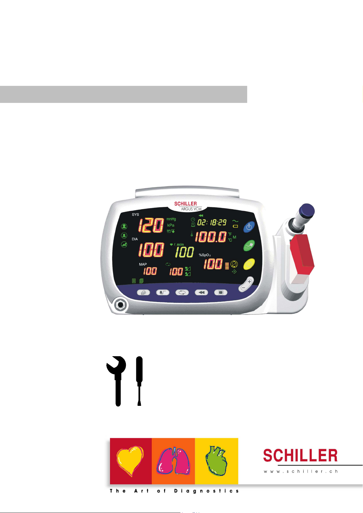
ARGUS VCM
Vital Compact Monitor
Art. No.: 2.540041 Rev. a *2.540041*
Service Handbook
Page 2

Contents
Figures
Tables
Notice
This document contains proprietary information that is protected by copyright. All Rights Reserved.
Reproduction, adaptation, or translation without prior written permission is prohibited, except as
allowed under the copyright laws.
Warranty
The information contained in this document is subject to change without notice.
Schiller makes no warranty of any kind with regard to this material, including, but not limited to, the
implied warranties or merchantability and fitness for a particular purpose.
Schiller shall not be liable for errors contained herein or for incidental or consequential damages in
connection with the furnishing, performance, or use of this material.
Revision History
The documentation part number and revision number indicate its current edition. The revision
number changes when a new edition is printed in accordance with the revision history of the
documentation. Minor corrections and updates which are incorporated at reprint do not cause the
revision number to change. The document part number changes when extensive technical changes are
incorporated.
ARGUS VCM Service Manual i
Page 3

Contents
ARGUS VCM
Introduction 1
Manual Overview ............................................................................................................................................ 3
Related Documents.......................................................................................................................................... 3
Description of the ARGUS VCM monitor .................................................................................................... 3
Specifications 7
Physical.............................................................................................................................................................. 7
Electrical ............................................................................................................................................................ 7
Environmental.................................................................................................................................................. 7
Measurement Parameters ...............................................................................................................................8
Compliance .....................................................................................................................................................10
Routine Maintenance 11
Cleaning ..........................................................................................................................................................11
Periodic Safety and Functional Checks....................................................................................................... 11
Functional Checks.......................................................................................................................................... 12
Batteries........................................................................................................................................................... 12
Environmental Protection............................................................................................................................. 12
Performance Verification 13
Introduction .................................................................................................................................................... 13
Equipment Needed........................................................................................................................................ 13
Performance Tests ..........................................................................................................................................14
Safety Tests...................................................................................................................................................... 21
Service Mode and Demo Mode 25
Introduction .................................................................................................................................................... 25
Service Mode ..................................................................................................................................................25
Demo Mode ....................................................................................................................................................31
Firmware download 33
Introduction .................................................................................................................................................... 33
Equipment Needed........................................................................................................................................ 33
How to Download .........................................................................................................................................33
Troubleshooting 35
Introduction .................................................................................................................................................... 35
How to Use This Section ...............................................................................................................................35
Who Should Perform Repairs.......................................................................................................................35
Replacement Level Supported ..................................................................................................................... 35
Troubleshooting Guide.................................................................................................................................. 36
Disassembly Guide 43
General ............................................................................................................................................................43
Replacement Level Supported ..................................................................................................................... 44
Prior to Disassembly...................................................................................................................................... 45
Fuse Replacement ..........................................................................................................................................45
Battery Replacement...................................................................................................................................... 45
Monitor Disassembly..................................................................................................................................... 46
Spare Parts 57
Introduction .................................................................................................................................................... 57
Obtaining Replacement Parts....................................................................................................................... 57
Parts List.......................................................................................................................................................... 58
ii ARGUS VCM Service Manual
Page 4

ARGUS VCM
Contents
Packing For Shipment 61
General Instructions ......................................................................................................................................61
Returning the ARGUS VCM......................................................................................................................... 61
Repacking In Original Carton ...................................................................................................................... 61
Repacking In a Different Carton.................................................................................................................. 62
System Processing Description 63
System Overview ...........................................................................................................................................63
NIBP Processing............................................................................................................................................. 66
SpO2 Processing............................................................................................................................................. 68
Temperature Processing ................................................................................................................................ 70
ARGUS VCM Service Manual iii
Page 5

Contents
ARGUS VCM
Figures
Figure 1. ARGUS VCM Front Panel............................................................................................................................................... 4
Figure 2. ARGUS VCM Rear Panel................................................................................................................................................ 5
Figure 3. ARGUS VCM Left Side Panel.......................................................................................................................................... 6
Figure 4. ARGUS VCM Right Side Panel....................................................................................................................................... 6
Figure 5. System Version............................................................................................................................................................... 25
Figure 6. Battery Voltage Level..................................................................................................................................................... 26
Figure 7. NIBP Inflation Cycle ..................................................................................................................................................... 26
Figure 8. Total Runtime ................................................................................................................................................................ 27
Figure 9. Factory Defaults Reset .................................................................................................................................................. 27
Figure 10. Night Panel ................................................................................................................................................................. 29
Figure 11. NIBP Calibration......................................................................................................................................................... 29
Figure 12. NIBP Pressure Test...................................................................................................................................................... 30
Figure 13. Sound Calibration ....................................................................................................................................................... 30
Figure 14. Demo Mode Display.................................................................................................................................................... 31
Figure 15. Disassembly Sequence Flow Chart............................................................................................................................. 44
Figure 16. Battery Disassembly.................................................................................................................................................... 45
Figure 17. Monitor Disassembly................................................................................................................................................... 46
Figure 18. Front Case Disassembly.............................................................................................................................................. 47
Figure 19. Main BD, SpO2, FND modules Disassembly .............................................................................................................. 48
Figure 20. Front Case Disassembly – Overlay, NIBP cuff hose connector................................................................................... 49
Figure 21. Rear Case Disassembly- Battery, SMPS...................................................................................................................... 50
Figure 22. Rear Case Disassembly- NIBP module ....................................................................................................................... 51
Figure 23. Rear Case Disassembly- Printer ................................................................................................................................. 52
Figure 24. Rear Case Disassembly – Speaker, Handle, etc........................................................................................................... 53
Figure 25. Temperature Case Disassembly – Temperature Module.............................................................................................. 54
Figure 26. Temperature Case Disassembly ................................................................................................................................... 55
Figure 27. ARGUS VCM Exploded View ...................................................................................................................................... 56
Figure 28. ARGUS VCM Exploded View – Spare Parts................................................................................................................ 58
Figure 29. ARGUS VCM System Block Diagram.......................................................................................................................... 63
Tables
Table 1. Required Test Equipments ............................................................................................................................................... 13
Table 2. Earth Leakage Current Values ........................................................................................................................................ 21
Table 3. Enclosure Leakage Current............................................................................................................................................. 22
Table 4. Patient Leakage Current Values ...................................................................................................................................... 22
Table 5. Patient Leakage Current Values—Mains Voltage on Applied Part.................................................................................. 23
Table 6. Test Lead Combinations .................................................................................................................................................. 24
Table 7. Allowable Leakage Current............................................................................................................................................. 24
Table 8. Factory Default Settings for ARGUS VCM..................................................................................................................... 28
Table 9. Required Equipments for Firmware download................................................................................................................ 33
Table 10. Technical Error Codes................................................................................................................................................... 42
Table 11. Part Descriptions – Monitor Assembly.......................................................................................................................... 46
Table 12. Part Descriptions – Front Case Assembly..................................................................................................................... 47
Table 13. Part Descriptions – Main BD, SpO2, FND Modules Assembly..................................................................................... 48
Table 14. Part Descriptions – Overlay, NIBP Cuff Hose Connector............................................................................................. 49
Table 15. Part Descriptions – Battery, SMPS Assembly ............................................................................................................... 50
Table 16. Part Descriptions – NIBP Module Assembly................................................................................................................. 51
Table 17. Part Descriptions – Printer Assembly........................................................................................................................... 52
Table 18. Part Descriptions – Speaker, Handle, etc Assembly...................................................................................................... 53
Table 19. Part Descriptions – Temperature Module Assembly...................................................................................................... 54
Table 20. Part Descriptions – Temperature Case Assembly.......................................................................................................... 55
Table 21. ARGUS VCM Parts List ................................................................................................................................................ 59
iv ARGUS VCM Service Manual
Page 6

Introduction
Manual Overview
Related Documents
Description of the ARGUS VCM monitor
Warnings
Warnings are identified by the WARNING symbol shown above.
Warnings alert the user to potential serious outcomes (death, injury, or adverse
events) to the patient or user.
WARNING: Explosion hazard. Do not use ARGUS VCM in the presence of
flammable anesthetics or gases.
WARNING: Do not spray, pour, or spill any liquid on ARGUS VCM, its accessories,
connectors, switches, or openings in the chassis.
WARNING: Do not immerse ARGUS VCM or its accessories in liquid or clean with
caustic or abrasive cleaners.
WARNING: Ensure that conductive portions of the cables do not come into contact
with any other conductive parts.
WARNING: Electrical shock hazard. Disconnect the power cord from ARGUS VCM
before attempting to open or disassemble ARGUS VCM.
WARNING: The use of accessories, transducers and cables other than those specified
may result in increased emission and/or decreased immunity of ARGUS VCM
monitor.
WARNING: Do not silence ARGUS VCM audible alarm or decrease its volume if
patient safety could be compromised.
WARNING: During safety tests, AC mains voltage will be present on the applied
part terminals. Exercise caution to avoid electrical shock hazard.
WARNING: Do not place ARGUS VCM into operation after repair or maintenance
until Performance, Safety Tests and NIBP Calibration listed in this service manual
have been performed. Failure of these tests could result in erroneous readings.
ARGUS VCM Service Manual 1
Page 7

Introduction
Cautions
ARGUS VCM
Cautions are identified by the Caution symbol shown above.
Cautions alert the user to exercise care necessary for the safe and effective use of
ARGUS VCM monitor.
CAUTION: Observe ESD (electrostatic discharge) precautions when working within
the unit and/or when disassembling and reassembling ARGUS VCM monitor and
when handling any of the components of ARGUS VCM monitor.
CAUTION: When reassembling ARGUS VCM, over-tightening could strip out the
screw holes in the cases, rendering it unusable.
CAUTION: If any problem with ARGUS VCM built in an optional printer, check a
printer’s door is closed well. Operating error may be caused if the cover is not closed
correctly.
CAUTION: If internal battery cable has been disconnected, pay particular attention to
polarity of the cable before reattaching. If battery cable polarity is reversed, it is likely
that circuit damage will occur.
CAUTION: Ferrite Cores are used for electromagnetic compatibility. Please do not
remove Ferrite Cores while disassembling or reassembling, otherwise the monitor can
be affected by electromagnetic interference and measure inaccurate data to be
displayed or stored.
2 ARGUS VCM Service Manual
Page 8

ARGUS VCM
Manual Overview
This manual contains information for servicing
The monitor subsequently referred to as
qualified service personnel should service this product. Before servicing
read the operator’s manual carefully for a thorough understanding of safe operation.
Read and understand all safety warnings and service notes printed in this service
manual and the operator’s manual.
This manual contains information about ARGUS VCM monitor. ARGUS VCM monitor
includes the following configuration:
Config. Features Config. Features
N Standard (NIBP + Pulse Rate) NP Standard + Printer
NS Standard + SpO2 NSP Standard + SpO2 + Printer
NT Standard + Temperature NTP Standard + Temperature+ Printer
NST Standard + SpO2 + Temperature NSTP Standard + SpO2 + Temperature + Printer
All information in this manual, including the illustrations, is based on the monitor
configured with Temperature, SpO
of these options, some information in this manual does not apply.
2 and Printer options. If your monitor lacks any
Related Documents
To perform test and troubleshooting procedures and to understand the principles of
operation and circuit analysis sections of this manual, you must know how to operate
the monitor. Refer to
To understand the various blood pressure cuffs, SpO
that work with the monitor, refer to the individual directions for use that accompany
these accessories.
ARGUS VCM operator’s manual.
Description of the ARGUS VCM monitor
The purpose and function of Schiller
blood pressure (systolic, diastolic, and mean arterial pressures), functional arterial
oxygen saturation, pulse rate, and temperature for adult, pediatric and neonate patients
in all hospital areas and hospital-type facilities. It may be used during hospital
transport and in mobile, land-based environments, such as ambulances, within the
specification of the environmental characteristics. Monitor users should be skilled at
the level of qualified health care professionals, such as a technician, doctor, nurse or
medical specialist.
Note: Hospital use typically covers such areas as general care floors, operating rooms,
special procedure areas, intensive and critical care areas, within the hospital plus
hospital-type facilities. Hospital-type facilities include physician office based facilities,
sleep labs, skilled nursing facilities, surgicenters, and sub-acutecenters.
Note: Intra-hospital transport includes transport of a patient within the hospital or
hospital-type facility.
ARGUS VCM monitor is to monitor noninvasive
Introduction
ARGUS VCM monitor.
ARGUS VCM throughout this manual. Only
ARGUS VCM,
2 sensors and temperature probes
ARGUS VCM Service Manual 3
Page 9
Introduction
ARGUS VCM
The physical and operational characteristics of the monitor are described in the
operator’s manual and in the Specification section of this manual.
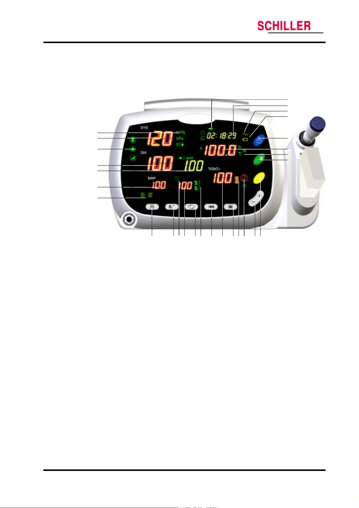
Figure 1 and 2 identify the displays, controls, indicators and symbols of the front and
rear panels.
1
2
3
4
5
6
7
28
27
26
25
2 4
23
22
21
8 9 10 11 12 13 14 15 16 1718 19 20
1. Blood Pressure Unit Indicators 15. %SpO
2 Display
2. Systolic Blood Pressure Display 16. Mode Button
3. Patient Type Indicators 17. Pulse Amplitude Indicator
4. Diastolic Blood Pressure Display 18. Alarm Silence Indicator
5. Pulse Rate Display 19. Up/Down Selection Button
6. MAP (Mean Arterial Pressure) Display 20. Alarm Silence Button
7. Print Setting Indicators 21. BP start/stop button
8. Print Button 22. Temperature Unit/Mode Indicators
9. Alarm Button 23. Temperature Display
10. Auto Indicator 24. Power Button
11. Auto Cycle Display 25. Battery Indicator
12. Auto Button 26. Charging/AC in Indicator
13. Pulse Tone/Alarm Volume Setting Indicators 27. Time Display
14. Review Button 28. Review Indicator
Figure 1. ARGUS VCM Front Panel
4 ARGUS VCM Service Manual
Page 10
ARGUS VCM
Introduction
1
2
AC IN
100-240V~,
50/60 Hz
28-38VA
3 4 5 6
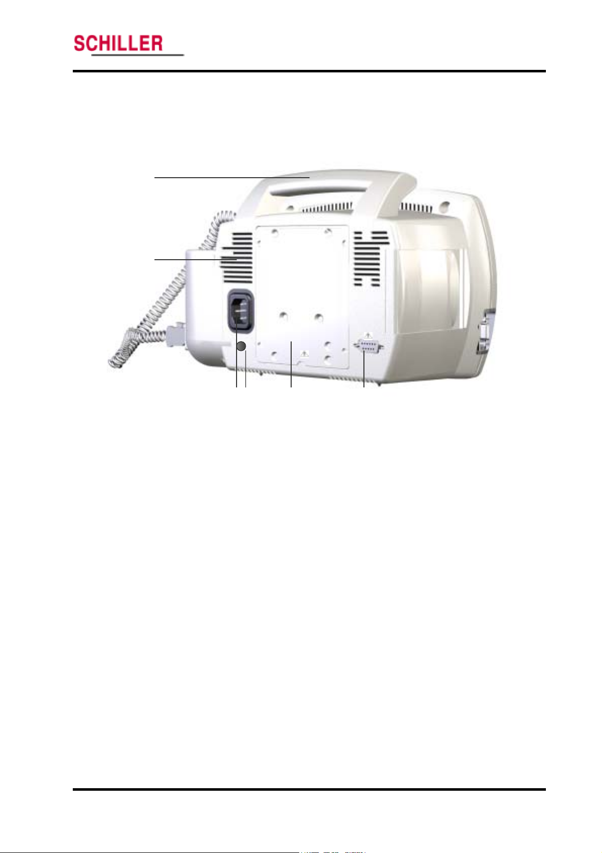
1. Handle 4. Equipotential (Ground)
2. Air Ventilator 5. Battery Cover (Replacement)
3. AC Power Connector 6. RS-232 Data Interface
Figure 2. ARGUS VCM Rear Panel
ARGUS VCM Service Manual 5
Page 11
Introduction
ARGUS VCM
1
2
3
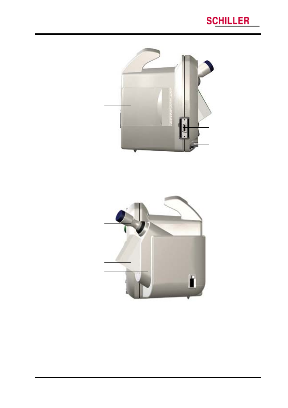
1. Printer 3. NIBP hose connector
2 sensor/cable connector
2. SpO
Figure 3. ARGUS VCM Left Side Panel
1
2
3
1. Temperature probe 3. Probe holder
2. Probe cover 4. Temperature probe connector
Figure 4. ARGUS VCM Right Side Panel
4
6 ARGUS VCM Service Manual
Page 12

Specification
Physical
Electrical
Environmental
Measurement Parameters
Compliance
Physical
Electrical
Instrument
Dimensions 130×180×278 (mm)
Weight 2.7 (kg)
AC Power
Power 100Vac to 240Vac, 50 Hz/60 Hz, 28 to 38 VA
Environmental
Battery
Type Lead acid
Voltage/Capacity 6 V/ 4 Ampere-Hours
Recharge 12 hours with ARGUS VCM
Shelf Life 2 months, new fully charged battery
Complies with 91/157/EEC
Operation
Temperature 10 °C (50 °F) to 40 °C (104 °F)
Exemption: thermometry module
– operating temperature 16 °C (60 °F) to 40 °C (104 °F)
Humidity 15 % RH to 95% RH, non-condensing
Altitude 170 m (557 ft) below sea level
4,877 m (16,000 ft) above sea level
Transport and Storage
Temperature –20 °C (-4 °F) to 50 °C (122 °F)
Humidity 15 % RH to 95% RH, non-condensing
Altitude –610 m (–2,000 ft) below sea level
12,192 m (40,000 ft) above sea level
Note: The system may not meet its performance specifications if stored or used outside the
manufacturer’s specified temperature and humidity range.
ARGUS VCM Service Manual 7
Page 13

Specification
Measurement Parameters
NIBP
Pulse Rate Range Adult/Pediatric/Neonatal 30 BPM to 220 BPM
Pulse Rate Accuracy ±3 BPM or ±3%, whichever is greater
Technique Oscillometric Measurement
Measurement modes AUTO, MANUAL and STAT
AUTO Mode Automatic NIBP measurements at intervals of 1, 2, 3, 4, 5, 10, 15,
MANUAL Mode Single measurement initiated by NIBP Start/Stop switch
STAT Mode Series of consecutive measurements for 5 minutes
NIBP pressure measurement range
Systolic pressure range
Diastolic pressure range
Mean pressure range
Pressure Display Accuracy Meets ANSI/AAMI SP10:1992+A1:1996
ARGUS VCM
Pulse Rate
NIBP (Non-Invasive Blood Pressure)
30, 45, 60, 90, 120, and 240 minutes
Adult: 30 mmHg to 260 mmHg (3.9 kPa to 34.5 kPa)
Pediatric: 30 mmHg to 160 mmHg (3.9 kPa to 21.2 kPa)
Neonatal: 25 mmHg to 120 mmHg (3.3 kPa to 15.9 kPa)
Adult: 20 mmHg to 235 mmHg (2.6 kPa to 31.2 kPa)
Pediatric: 15 mmHg to 130 mmHg (1.9 kPa to 17.2 kPa)
Neonatal: 10 mmHg to 105 mmHg (1.3 kPa to 13.9 kPa)
Adult: 20 mmHg to 255 mmHg (2.6 kPa to 33.9 kPa)
Pediatric: 15 mmHg to 140 mmHg (1.9 kPa to 18.6 kPa)
Neonatal: 10 mmHg to 110 mmHg (1.3 kPa to 14.6 kPa)
Cuff Pressure Range 0 to 300 mmHg (0 to 40 kPa)
Initial Cuff Inflation
Overpressure protector
Standards ANSI/AAMI SP10:1992+A1:1996, IEC60601-2-30:1999
Note: Systolic and diastolic blood pressure measurements determined with this device are equivalent to
those obtained by a trained observer using the cuff/stethoscope auscultation method, within the limits
prescribed by the American National Standard, Electronic or automated sphygmomanometers.
Adult:
100, 120, 140, 160(Default), 180, 200, 220, 240, 270 mmHg
(13.3, 15.9, 18.6, 21.2(default), 23.9, 26.6, 29.2, 31.9, 35.9 kPa)
Pediatric:
80, 90, 100, 110, 120(default), 130, 140, 150, 160, 170 mmHg
(10.6, 11.9, 13.3, 14.6, 15.9(default), 17.2, 18.6, 19.9, 21.2, 22.6 kPa)
Neonatal:
50, 60, 70, 80, 90(default), 100, 110, 120, 132 mmHg
(6.6, 7.9, 9.3, 10.6, 11.9(default), 13.3, 14.6, 15.9, 17.5 kPa)
Adult 280 mmHg (N.C.), 308 mmHg (S.F.C.)
Pediatric 220 mmHg Neonatal 154 mmHg
EN1060-1:1995 and EN1060-3:1997.
8 ARGUS VCM Service Manual
Page 14

ARGUS VCM
SpO2/Pulse Rate
Specification
%Saturation
Range 1% to 100%
Low Perfusion 0.03% to 20%
Accuracy Without Motion-Adults 70% to 100% ±2 digits
1% to 69% unspecified
Without Motion-Neonate1 70% to 100% ±3 digits
1% to 69% unspecified
Low Perfusion
Range 20 BPM to 300 BPM
Accuracy Without Motion2 20 BPM to 300 BPM ±3 digits
Low Perfusion
2
70% to 100% ±2 digits
1% to 69% unspecified
Pulse Rate
2
20 BPM to 300 BPM ±3 digits
Temperature
Printer
Standards EN865:1997
1
Neonate specifications are shown for neonate sensors with ARGUS VCM. Saturation accuracy will vary
by sensor type recommended by the manufacturer..
2
Specification applies to monitor performance and was validated with Biotek and Nellcor simulators
Probe Type Thermistor probe
Range 26° C to 43° C (80° F to 110°F)
Display Accuracy ±0.1° C (±0.2° F)
Measurement units ° C, ° F
Measurement modes Predictive, Monitored
Predictive Mode One-time measurement in a single temperature reading which
is displayed at the end of the brief measurement period
Monitored Mode Continuous measurement over an indefinite period.
Standards ASTM E1112-00, EN12470-3
Typ e Thermal
Resolution 8 (dots/mm)
Printing speed 45 (mm/s)
Paper width 57 (mm)
ARGUS VCM Service Manual 9
Page 15

Specification
Compliance
ARGUS VCM
Item Compliant with
Classification Class I (on AC power) Internally powered (on battery power)
Type of
protection
General Safety IEC60601-1:1998+A1:1991+A2:1995
Alarms IEC60601-1-8:2001 Draft
Non-invasive
blood pressure
Oxygen
saturation
Type BF – Applied part
General requirements for Safety and Essential Performance
Alarm systems requirements, tests and guidances in medical
electrical equipments systems
AAMI SP10:1992+A1:1996
Electronic or Automated Sphygmomanometers
EN1060-1:1995 Non-invasive sphygmomanometers
EN1060-3:1997
Supplementary requirements for electrical-mechanical blood
pressure measuring systems
IEC60601-2-30:1999
Particular requirements for the Safety, including essential
performance, of automatic cycling indirect blood pressure
monitoring equipment
EN865:1997 Pulse oximeters, Particular requirements
Temperature
monitoring
Electromagnetic
Compatibility
Labeling EN1041:1998
Marking IEC 60878, EN 980, ISO 7000, EN 60417-1, EN 60417-2
E1112-00
Electronic thermometer for intermittent determination of patient
temperature
EN12470-3:2000
Performance of compact electrical thermometers (non-predictive
and predictive) with maximum device
IEC 60601-1, sub clause 36, IEC/
IEC60601-1-2:2001
Electromagnetic compatibility-requirements & test
Information supplied by the manufacturer with medical devices
10 ARGUS VCM Service Manual
Page 16

Routine Maintenance
Cleaning
Periodic Safety and Functional Checks
Functional Checks
Batteries
Environmental Protection
WARNING: Do not spray or pour any liquid on the monitor or its accessories. Do
not immerse ARGUS VCM or its accessories in liquid or clean with caustic or
abrasive cleaners.
Cleaning
To clean ARGUS VCM, dampen a cloth with a commercial, nonabrasive cleaner and wipe
the exterior surfaces lightly.
CAUTION: Do not allow any liquids to come in contact with the power connector or
switches or to penetrate connectors or openings in the instrument.
Note: For cuffs, sensors and probes, follow the cleaning instructions in the directions
for use that accompany these accessories.
Note: If liquid is spilled on the monitor, clean and dry thoroughly before reuse.
Note: If in doubt about the monitor safety, refer the unit to qualified service personnel.
For surface-cleaning, follow your institution’s procedures or:
ARGUS VCM may be surface-cleaned by using a soft cloth dampened with
either a commercial or nonabrasive cleaner, and lightly wiping the top,
bottom, and front surfaces of the monitor lightly.
Periodic Safety and Functional Checks
ARGUS VCM requires no routine service or calibration other than cleaning and battery
maintenance. The following performance verification tests may be used following repair
or during routine maintenance (if required by your local institution).
1. Inspect the exterior of
2. Inspect labels for legibility. If the labels are not legible, contact Schiller Technical
Services Department.
3. Verify that the unit performs properly as described in Performance Verification
section.
4. Perform the electrical safety tests detailed in Performance Verification section. If the
unit fails these electrical safety tests, do not attempt to repair. Contact Schiller
Technical Services Department.
ARGUS VCM for damage.
ARGUS VCM Service Manual 11
Page 17

Routine Maintenance
Functional Checks
The following checks should be performed at least every 2 years by a qualified service
technician.
1. If the monitor has been visibly damaged or subjected to mechanical shock (for
example, if dropped), perform the performance tests as described in Performance
Verification section.
2. Perform the electrical safety tests as described in Safety Tests section. If the unit fails
these electrical safety tests, refer to Troubleshooting section.
3. Inspect the fuses for proper value and rating
- qty 2, 2.0 A, 250 volts for AC mains (L/N: F1, F2)
- qty 1, 6.3 A, 250 volts for internal battery (L/N: F3)
Batteries
If ARGUS VCM has not been used for a long period of time, more than 2 months, the
battery will need charging. To charge the battery, connect
as described in Performance Verification section of this service manual or the Battery
Operation section of the operator’s manual.
Schiller recommends replacing the instrument’s battery every 2 years. When
VCM
is going to be stored for 2 months or more, it is recommended to remove the
battery prior to storage. To replace or remove the battery, refer to Disassembly Guide.
Note: Storing
the battery capacity. The battery may require a full charge/discharge cycle to
restore normal capacity. A full charge of a dead battery takes approximately 12
hours while the monitor is turned off. Schiller recommends that
sealed, lead acid batteries be replaced at 2-year intervals. Refer to Disassembly
Guide Section.
CAUTION: If ARGUS VCM is to be stored for a period of 2 months or longer, it is
recommended to notify service personnel to remove the battery from the monitor prior
to storage. Recharging the battery is strongly recommended when the battery has not
been recharged for 2 or more months.
CAUTION: If the battery shows any signs of damage, leakage, or cracking, it must be
replaced immediately.
CAUTION: Discarded battery may explode during incineration. Recycle used batteries
properly. Do not dispose of batteries in refuse containers.
ARGUS VCM for a long period without charging the battery may degrade
Environmental Protection
Follow local governing ordinances and recycling plans regarding disposal or recycling
batteries and other device components.
ARGUS VCM
ARGUS VCM to an AC outlet
ARGUS
ARGUS VCM’s
12 ARGUS VCM Service Manual
Page 18

Performance Verification
Introduction
Equipment Needed
Performance Tests
Safety Tests
Introduction
This section discusses the tests used to verify performance following repairs or during
routine maintenance. All tests can be performed without removing
All tests except battery charge and battery performance tests must be performed as the
last operation before the monitor is returned to the user.
If
ARGUS VCM fails to perform as specified in any test, repairs must be made to correct
the problem before the monitor is returned to the user.
Equipment Needed
Table 1 lists the equipment required for performance verification.
Table 1. Required Test Equipments
ARGUS VCM covers.
Equipment Description
Digital Multi Meter (DMM) Fluke Model 87 or Equivalent
NIBP Cuff Durable, Adult 11cm
NIBP Cuff Durable, Neonatal 5cm
NIBP Hose Adult, 8 feet
NIBP Hose Neonatal, 6 feet
NIBP Rigid PVC Vessel 9cm diameter
NIBP Rigid PVC Vessel 5cm diameter
SpO2 Sensor Extension Cable DOC-10
Temperature Probe Oral Probe
NIBP Simulator Bio-Tek BP Pump 2 or Equivalent
SpO2 Simulator NELLCOR SRC-MAX
Temperature Simulator WelchAllyn 9600 Calibration Tester
Safety Analyzer METRON QA-90 or Equivalent
Stopwatch Manual or electronic
ARGUS VCM Service Manual 13
Page 19

Performance Verification
Performance Tests
The battery charge and battery performance test should be performed before the
monitor repairs whenever the battery is suspected as being a source of the problems.
All other tests may be used following repairs or during routine maintenance (if
required by your local institution). Before performing the battery performance test,
ensure that the battery is fully charged. This section is written using factory defaults set
as power-up. If your institution has preconfigured custom defaults, those values will be
displayed.
Power
1. Connect the monitor to AC power source using proper power cord.
2. Verify Charging/AC in indicator is lit (or flashing).
3. Press Power button over 1 second, and then verify that the monitor is turned on.
4. After the monitor operates in normal mode, disconnect the power cord.
5. Verify Battery indicator is lit instead of Charging/AC in indicator.
6. Press Power button over 1 second, and then verify that the monitor is turned off.
Battery Charge
1. Connect the monitor to AC power source using proper power cord. (the monitor is
turned off)
2. Verify Charging/AC in indicator is lit (or flashing).
ARGUS VCM
Note: If Charging/AC in indicator is flashing, the battery needs fully charging.
3. Charge the battery fully until Charging/AC in indicator is no more flashing. It takes
for at least 12 hours.
4. To check for a full charge, disconnect the power cord. Press Power button and the
NIBP start/stop button simultaneously over 1 second to enter the Service mode. Then
select battery voltage level displayed.
5. Verify that current battery voltage display in Service mode indicates ‘6.0V’ or greater.
Note: The battery may require a complete charge/discharge cycle to restore its normal
capacity, depending on its previous usage.
Battery Discharge
1. Disconnect the power cord from the monitor with fully charged battery.
2. Turn on the monitor by pressing Power button over 1 second.
3. Connect NIBP simulator to the monitor. Set NIBP simulator:
SYS of 120mmHg, DIA of 80mmHg, PR of 80 bpm.
4. Set NIBP Auto interval of the monitor to 15 minutes.
5. After more than 2 hours of the monitor operating, verify an audible alarm is sounding
and the battery level of the monitor is under 5.4V.
6. Allow the monitor to operate until it automatically powers down due to low battery
condition. Verify that high priority alarm occurs 5 seconds before the monitor
automatically shuts down.
7. If the monitor passes this test, immediately recharge battery.
14 ARGUS VCM Service Manual
Page 20

ARGUS VCM
Performance Verification
Power-On Self-Test
1. Connect the monitor to AC power source and verify Charging/AC in indicator is lit.
2. Observe the monitor front panel. With the monitor off, press Power button. The
Note: Power-on self-test takes approximately 7 seconds to complete.
Note: If an error code is displayed, please refer to Troubleshooting section.
monitor must perform the following sequence.
a. All FNDs and indicators are illuminated.
b. Power-on beeps sounds consecutively.
c. Upon successful completion of power-on self-test, the display will enter the
normal mode.
General Operation Tests
Alarms and Alarm Silence
1. Connect the monitor to an AC power source.
2. Press the monitor Power button to turn the monitor on.
3. Connect NIBP simulator to the monitor.
4. Set NIBP simulator as follows:
Systolic of 120mmHg, Diastolic of 80mmHg and pulse rate of 150 bpm.
5. Press NIBP start/stop button.
6. Verify following the monitor reaction after measurement completes:
a. The monitor displays NIBP and pulse rate as specified by the simulator.
b. Audible alarm sounds and Pulse rate display flashes indicating the parameter
has violated default alarm limits.
7. Press Alarm silence button on the front panel of the monitor.
8. Verify the following:
a. An audible alarm is temporarily silenced.
b. Pulse rate display continues flashing.
c. Alarm silence indicator is lit.
d. Audible alarm returns in approximately 90 seconds.
9. Set NIBP simulator as follows:
Systolic of 120mmHg, Diastolic of 80mmHg and pulse rate of 80 bpm.
10. Press NIBP start/stop button.
11. Verify following the monitor reaction after measurement completes:
a. The monitor displays NIBP and pulse rate as specified by the simulator.
b. The alarm is terminated.
12. Disconnect NIBP simulator from the monitor.
13. Kink NIBP cuff hose connector of monitor and then press NIBP start/stop button.
14. Verify that the monitor displays an error code, E23 and sounds audible alarm.
15. Press Alarm silence button.
16. Verify that the alarm is terminated.
ARGUS VCM Service Manual 15
Page 21

Performance Verification
Pulse Tone Volume Control
1. Connect the monitor to an AC power source.
2. Press Power button to turn the monitor on.
3. Connect SpO
monitor.
4. Set SpO
5. Verify SpO2/ pulse rate values and pulse amplitude indicator correctly display, and
pulse tone sounds.
6. Press the mode button to enter setting mode.
7. Press Up (+) selection button to adjust pulse tone volume from 1 to 8. Return to the
monitoring screen.
8. Verify beeping pulse tone increases.
9. Press the mode button to enter setting mode.
10. Press Down (-) selection button to adjust pulse tone volume from 8 to 1. Return to
the monitoring screen.
11. Verify beeping pulse tone decreases.
12. Set pulse tone volume to 0, and return to the monitoring screen. Verify pulse tone is
no longer audible.
2 simulator as follows: SpO2 of 90% and pulse rate of 60 bpm.
ARGUS VCM
2 simulator to the pulse oximetry cable and connect the cable to the
13. Return pulse tone volume to a comfortable level.
Alarm Volume Control
1. Connect the monitor to an AC power source.
2. Press Power button to turn the monitor on.
3. Kink NIBP cuff hose connector of the monitor and then press NIBP start/stop button.
4. Verify that the monitor ‘E23’ displays and sounds audible alarm.
5. Press the mode button to enter setting mode.
6. Press Up (+) selection button to adjust alarm volume from 1 to 8. Return to the
monitoring screen.
7. Verify alarm tone increases.
8. Press the mode button to enter setting mode.
9. Press Down (-) selection button to adjust alarm volume from 8 to 1. Return to the
monitoring screen.
10. Verify alarm tone decreases.
11. Return alarm volume to a comfortable level.
Real-Time Clock
1. Connect the monitor to an AC power source.
2. Press Power button to turn the monitor on.
3. Verify that Time display updates every second.
16 ARGUS VCM Service Manual
Page 22

ARGUS VCM
Printer Test
Flash Memory
Performance Verification
If Printer option installed, the following test procedures will verify printer performance.
1. Connect the monitor to an AC power source.
2. Press Power button to turn the monitor on.
3. Connect all necessary simulators to the monitor.
4. Press Printer button when the monitor displays the measurements.
5. Verify the measurement values are printed out correctly.
6. Press the mode button over 3 seconds (configuration mode) to select Stream print.
7. Kink NIBP cuff hose connector of the monitor and then press NIBP start/stop button.
8. Verify that the monitor ‘E23’ displays and also prints out.
9. Open the printer door, and then press Print button.
10. Verify that the monitor sounds ‘invalid button tone’.
Perform the following procedure to test the flash memory.
1. Connect the monitor to an AC power source.
2. Press Power button to turn the monitor on.
3. Change alarm limits and other settings.
Temperature mode C M
Alarm Limit, SYS HI 160
Alarm Limit, DIA LO 15
Alarm Limit, PR HI 180
Alarm Limit, SpO
4. Kink NIBP cuff hose connector of the monitor to generate an error ‘E23’.
5. Turn the monitor off.
6. Press Power button to turn the monitor on again.
7. Verify that previously changed alarm limits and settings are saved/displayed.
8. Press Review button. Verify that ‘E23’ event is saved/displayed.
9. Turn the monitor off.
10. Press Power button & NIBP start/stop button simultaneously to enter Service mode.
11. Set ‘DEFAULT RESET’ to ‘YES’. The monitor will return to the factory defaults.
12. Turn the monitor off.
13. Press Power button to turn the monitor on again.
14. Verify that alarm limits and settings of the monitor are set to the factory defaults.
Refer to Table 8 Factory defaults.
15. Press Review button. Verify invalid button tone sounds and all events of trend data
has been removed.
2 LO 85
ARGUS VCM Service Manual 17
Page 23

Performance Verification
Measurement Parameter Operation Tests
Pneumatic System Operation
These tests verify the functionality of
1. Place the neonatal cuff with a rigid PVC vessel (5cm diameter). Connect the cuff to
NIBP cuff hose connector via the neonatal hose.
2. Connect the monitor to an AC power source, and then press Power button to turn the
monitor on.
3. Press NIBP start/stop button.
4. Verify that Systolic blood pressure display indicates an error code E23 and an audible
alarm sounds.
5. Press the mode button (setting mode) to change Patient type to Neonatal. Return to
the monitoring screen.
6. Press NIBP start/stop button. Verify that the monitor inflates.
7. Press NIBP start/stop button. Verify that the monitor deflates.
8. Place the adult cuff with a rigid PVC vessel (9cm diameter). Connect the cuff to NIBP
cuff hose connector via the adult hose.
9. Press NIBP start/stop button.
10. Verify that Systolic blood pressure display indicates an error code E22 (or E24) and
an audible alarm sounds.
11. Press the mode button (setting mode) to change Patient type to Adult. Return to the
monitoring screen.
12. Press NIBP start/stop button. Verify that the monitor inflates.
13. Press NIBP start/stop button. Verify that the monitor deflates.
NIBP air leakage test
1. Connect the monitor to an AC power source.
2. Press Power button and NIBP start/stop button to enter Service mode.
3. Select NIBP Pressure Test by pressing Mode button (see figure 12).
4. Set a desired target pressure between 50and 300mmHg by pressing Up/Down (+/-)
selection buttons.
5. Place the adult cuff with a rigid PVC vessel (9cm diameter). Connect the cuff and the
adult hose to NIBP simulator. Then connect the adult hose to the monitor.
6. Set NIBP simulator to Pressure test or Leakage test mode.
7. Select the set point of NIBP simulator as the same point of target pressure of the
monitor.
8. Press NIBP start/stop button of the monitor as simultaneously pressing start button of
NIBP simulator. Current pressure appears on the diastolic pressure display.
9. After current inflating pressure comes up to the desired target pressure, the monitor
starts deflating. Ensure that air leakage rate displays.
10. Verify that air leakage rate is within 6mmHg/min.
ARGUS VCM
ARGUS VCM pneumatic system.
18 ARGUS VCM Service Manual
Page 24

ARGUS VCM
Performance Verification
NIBP overpressure test
1. Connect the monitor to an AC power source, and then press Power button to turn the
monitor on.
2. Press Mode button. Set to Adult patient type and NIBP target pressure, 270mmHg.
3. Place the adult cuff with a rigid PVC vessel (9cm diameter). Connect the cuff and the
adult hose to NIBP simulator. Then connect the adult hose to the monitor.
4. Set NIBP simulator to Pressure relief or Overpressure test mode.
5. Press NIBP start/stop button of the monitor as simultaneously pressing start button of
NIBP simulator. NIBP simulator pressurizes the system until the monitor’s overpressure relief system activates.
6. Verify that peak point displayed on NIBP simulator (point of protection pressure) is
within 300mmHg.
Also this point of protection pressure may be verified at the moment of the monitor’s
NIBP valve of relieved.
NIBP transducer accuracy test
1. Follow the procedure of NIBP air leakage test specified above.
2. During the deflation of the cuff pressure, verify that the difference is within ±3mmHg
between monitor’s current pressure and simulator’s current pressure.
Pulse Oximetry Operation
2 option installed, the following test procedures will verify SpO2 performance.
If SpO
1. Connect the monitor to an AC power source.
2. Turn on the monitor by pressing Power button.
3. Connect SpO
monitor.
4. Set SpO
5. The monitor will:
- sound an audible alarm
- display an SpO
- display a pulse rate of 60 ±3 bpm
- display Pulse amplitude indicator
6. Disconnect the pulse oximetry cable from the monitor.
7. Verify that the monitor displays an error code, E42 and sounds audible alarm.
2 simulator as follows: SpO2 of 75% and pulse rate of 60 bpm.
2 simulator to the pulse oximetry cable and connect the cable to the
2 of 75 ±2 digits (flashing)
ARGUS VCM Service Manual 19
Page 25

Performance Verification
Temperature Operation
If Temperature option installed, the following test procedures will verify temperature
performance.
1. Connect the monitor to an AC power source.
2. Press Power button to turn the monitor on.
3. Connect temperature probe to the temperature connector of the monitor.
4. Set Temperature tester to 96.4
5. Press the mode button (setting mode) to select ‘F M’ (monitored mode).
6. Insert the temperature probe into ‘…’ of Temperature tester when ‘Ready’ indicator of
the test is on.
7. After 3 minutes, verify that the monitor displays 96.1
Measurement accuracy: ±0.2° F
Temperature tester accuracy: ±0.1° F
8. Return the probe into the probe holder.
9. Verify that Temperature display indicates ‘- -‘.
ARGUS VCM
° F.
° F ~ 96.7° F.
20 ARGUS VCM Service Manual
Page 26

ARGUS VCM
Safety Tests
ARGUS VCM
IEC60601-1, Clause 19 (Second Edition, 1988; Amendment 1, 1991-11, Amendment 2,
1995-03), for instruments classified as Class I, Type BF.
Protective Earth Continuity
This test checks the integrity of the power cord ground wire from the AC plug to the
instrument chassis ground. The current used for this test is less than or equal to 4 Volts
RMS, 50 to 60 Hz, and 25 Amperes.
1. Connect the monitor AC mains plug to the analyzer as recommended by the analyzer
operating instructions.
2. Connect the analyzer resistance input lead to the equipotential terminal (ground lug)
on the rear of the instrument. Verify that the analyzer indicates 100 milliohms or less.
Electrical Leakage
Earth Leakage Current
This test is in compliance with IEC60601-1 earth leakage current. The applied voltage for
IEC60601-1 the voltage is 264 Volts AC, 50 to 60 Hz. All measurements shall be made
with the power switch in both “On” and “Off” positions.
1. Connect the monitor AC plug to the electrical safety analyzer as recommended by the
analyzer operating instructions.
2. Perform test as recommended by analyzer operating instructions.
safety tests meet the standards of, and are performed in accordance with,
Performance Verification
Normal Condition (NC) 500
SFC Open Supply (SFC OS) 1000
Normal Condition RM (NCRM) 500
SFC Open Supply RM (SFC OSRM) 1000
Note: Earth leakage current is measured under various conditions of the AC mains and
protective earth conductor. For each condition, the measured leakage current must
not exceed that indicated in Table 2.
Note: NC-normal condition
Enclosure Leakage Current
This test is in compliance with IEC60601-1 enclosure leakage current. This test is for
ungrounded enclosure current, measured between enclosure parts and earth. The
applied voltage for IEC60601-1 the applied voltage is 264 Volts AC at 50 to 60 Hz.
1. Connect the monitor AC plug to the electrical safety analyzer as recommended by the
analyzer operating instructions.
2. Place a 200 cm
contact with any metal parts of the enclosure that may be grounded.
Table 2. Earth Leakage Current Values
Test Condition Allowable Leakage Current (microamps)
/ SFC-single fault condition / RM-reverse mains/line voltage
2
foil in contact with the instrument case making sure the foil is not in
ARGUS VCM Service Manual 21
Page 27

Performance Verification
3. Measure the leakage current between the foil and earth.
Note: The analyzer leakage current indication must note exceed the values listed in Table
3.
ARGUS VCM
Table 3. Enclosure Leakage Current
Normal Condition RM (NCRM) 100
SFC Open Supply RM (SFC OSRM) 500
SRC Open Earch RM (SFC OERM) 500
Patient Leakage Current
This test measures patient leakage current in accordance with IEC60601-1, clause 19, for
Class I, Type BF equipment. Patient leakage current in this test is measured from any
individual patient connection to earth (power ground).
1. Configure the electrical safety analyzer as recommended by the analyzer operating
instructions.
2. Connect the monitor’s AC mains power cord to the analyzer as recommended by the
analyzer operating instructions.
3. Apply NIBP cuff wrapped tightly around an appropriate metal cylinder.
4. Connect a test cable between the cylinder and an input connector on analyzer.
5. Turn on
6. Perform the patient leakage current test as recommended by the analyzer operating
instructions.
7. Repeat the patient leakage current test for SpO
if those options configured, using the appropriate test cables.
Note: Patient leakage current is measured under various conditions of the AC mains and
protective earth conductor. For each condition, the measured leakage current must
not exceed that indicated in Table 4.
Note: This test requires a test cable for each patient connector. Test cables for NIBP, SpO
and temperature can be configured in a similar manner, by wrapping each sensor
end individually with aluminum foil filled with conductive gel (only enough gel to
ensure conductivity). Attach a wire to the foil that is connected to a test lead from
the electrical safety analyzer.
Test Condition
Normal Condiction (NC) 100
SFC Open Supply (OS) 500
SFC Open Earch (SFC OE) 500
ARGUS VCM.
Allowable Leakage Current (microamps)
2 and temperature patient connections,
2
Table 4. Patient Leakage Current Values
Test Condition
Normal Condiction (NC) 100
SFC Open Supply (OS) 500
SFC Open Earch (SFC OE) 500
Normal Condition RM (NCRM) 100
SFC Open Supply RM (SFC OSRM) 500
SRC Open Earch RM (SFC OERM) 500
22 ARGUS VCM Service Manual
Allowable Leakage Current (microamps)
Page 28

ARGUS VCM
Patient Leakage Current - (Mains Voltage on the Applied Part)
WARNING: AC mains voltage will be present on the applied part terminals during
this test. Exercise caution to avoid electrical shock hazard.
WARNING: Do not touch the patient leads clips or the simulator parts connected to
patient leads during this test as an electrical shock will occur.
This test measures patient leakage current in accordance with IEC60601-1, clause 19, for
Class I, type BF equipment. In this test, 110% of mains voltage is applied between each
patient connection and earth (power ground). Patient leakage current is then measured
from any individual patient connection to earth.
Note: Keep the patient test cable length as short as possible during the leakage test.
Note: This test requires the same test cables for each patient connector as described
above Patient Leakage Current.
1. Configure electrical safety analyzer as recommended by analyzer operating
instructions.
2. Connect the monitor’s AC mains power cord to analyzer as recommended by analyzer
operating instructions.
3. Apply NIBP cuff wrapped tightly around an appropriate metal cylinder.
4. Connect a test cable between the cylinder and an input connector on analyzer.
5. Turn on
6. Perform test as recommended by analyzer operating instructions.
7. Repeat test for SpO
using appropriate test cables.
Note: Patient leakage current is measured with normal and reverse mains polarity. For
ARGUS VCM.
2 and temperature patient connections, if those options configured,
each condition, the measured leakage current must not exceed that indicated in
Table 5.
Performance Verification
Table 5. Patient Leakage Current Values—Mains Voltage on Applied Part
Reverse polarity (SFCRM) 5000
Patient Auxiliary Current
This test measures patient auxiliary current in accordance with IEC60601-1, clause 19, for
Class I, type BF equipment. The applied voltage for IEC60601-1 the voltage is 264 volts,
50 to 60 Hz. Patient auxiliary current is measured between each test cable for all possible
connections.
Note: Keep the patient test cable length as short as possible during the leakage test.
Note: This test requires the same test cables for each patient connector as described in
Patient Leakage Current.
Test Condition
Normal polarity (SFC) 5000
Allowable Leakage Current (microamps)
ARGUS VCM Service Manual 23
Page 29

Performance Verification
1. Configure the electrical safety analyzer as recommended by the electrical analyzer’s
operating instructions.
2. Connect monitor’s AC mains power cord to the electrical analyzer as recommended by
the electrical analyzer’s operating instructions.
3. Connect the patient test lead combination in table 6 to the appropriate input connector
on the electrical analyzer.
4. Turn on ARGUS VCM.
5. Perform patient auxiliary current test per table 7 as recommended by electrical
analyzer’s operating instructions.
6. Repeat the patient auxiliary current test for each test lead combination as listed in
Table 7 and measure each patient auxiliary current.
ARGUS VCM
Table 6. Test Lead Combinations
First Test Lead
Temperature probe NIBP cuff
Temperature probe SpO2 sensor
NIBP cuff SpO2 sensor
Second Test Lead
Table 7. Allowable Leakage Current
Test Condition
Normal Condiction (NC) 100
SFC Open Supply (OS) 500
SFC Open Earch (SFC OE) 500
Normal Condition RM (NCRM) 100
SFC Open Supply RM (SFC OSRM) 500
SRC Open Earch RM (SFC OERM) 500
Allowable Leakage Current (microamps)
24 ARGUS VCM Service Manual
Page 30

Service Mode and Demo Mode
Introduction
Service Mode
Demo Mode
Introduction
This section describes Service mode that allows authorized personnel to review/check
system version, battery voltage level, NIBP inflation cycle, total system runtime, factory
default reset, night panel, NIBP calibration, NIBP pressure test and sound calibration in
order to obtain service-related information about the monitor. Also this section explains
how to demonstrate the monitor (Demo mode).
Service Mode
Follow the procedure below to enter Service mode.
1. With the monitor powered off, press Power button and NIBP start/stop button
simultaneously.
2. System version displays on the monitor.
3. Press Mode button to select a mode item.
System Version
The revision level of the system software displays: system software version, NIBP
module version, SpO
System version
2 module version and Temperature module version.
NIBP module version
SpO2 module version
Temperature module version
Figure 5. System Version
ARGUS VCM Service Manual 25
Page 31

Service Mode and Demo Mode
Battery Voltage Level
Current battery voltage level is displayed (unit of voltage: V).
NIBP Inflation Cycle
The number of NIBP inflation cycles operated is displayed.
Figure 6. Battery Voltage Level
ARGUS VCM
Note: The values of NIBP inflation cycle may not be reset, but it will be reset to zero
when a new Main PCB assembly is installed.
Figure 7. NIBP Inflation Cycle
26 ARGUS VCM Service Manual
Page 32

ARGUS VCM
Total System Runtime
Total Runtime displays the number of hours, rounded to the nearest hour, that the
monitor has been operational.
Note: The values of Total Runtime may not be reset, but it will be reset to zero when a
new Main PCB assembly is installed.
Factory Default Reset
To reset the monitor operating parameters to the factory default settings, press the
Mode button until “ DEFAULT RESET=NO” is displayed.
To reset to the factory default values, select ‘YES’ using only Up (+) selection button.
The monitor immediately resets to the defaults and the confirmation tone sounds.
To leave the settings unchanged, select ‘NO’ using only Down (-) selection button.
Service Mode and Demo Mode
Figure 8. Total Runtime
Figure 9. Factory Defaults Reset
ARGUS VCM Service Manual 27
Page 33

Service Mode and Demo Mode
Factory default settings are described in Table 8.
Table 8. Factory Default Settings for ARGUS VCM
Parameter Ranges Defaults
Systolic (mmHg) Neonatal Low: 25 to 115 High: 30 to 120 50, 100
Alarm Limits Pediatric Low: 30 to 155 High: 35 to 160 75, 145
Adult Low: 30 to 255 High: 35 to 260 75, 220
Diastolic
(mmHg)
Alarm Limits Pediatric Low: 15 to 125 High: 20 to 130 35, 100
Adult Low: 20 to 250 High: 25 to 255 35, 110
MAP (mmHg) Neonatal Low: 10 to 105 High: 15 to 110 35, 80
Alarm Limits Pediatric Low: 15 to 135 High: 20 to 140 50, 110
Adult Low: 20 to 250 High: 25 to 255 50, 120
PR (bpm) Neonatal Low: 25 to 295 High: 30 to 300 100, 200
Alarm Limits Pediatric Low: 25 to 295 High: 30 to 300 50, 150
Adult Low: 25 to 295 High: 30 to 300 50, 120
SpO2 % Neonatal Low: 50 to 98 High: 52 to 100 85, 98
Alarm Limits Pediatric Low: 50 to 98 High: 52 to 100 90, 100
Adult Low: 50 to 98 High: 52 to 100 90, 100
Patient Type Adult, Pediatric, Neonatal Adult
NIBP Units mmHg, kPa mmHg
NIBP initial
cuff inflation
Pediatric
Adult
NIBP Auto Interval Off, STAT, 1, 2, 3, 4, 5, 10, 15, 30,
Temperature Units/Modes °C, °F, °C M, °F M °F
Pulse Tone Volume 0 to 8 4
Alarm Volume 1 to 8 4
Night Panel On, Off Off
Print Control Manual, Stream Manual
Neonatal Low: 10 to 100 High: 15 to 105 30, 70
Neonatal
ARGUS VCM
50, 60, 70, 80, 90, 100, 110, 120, 132 mmHg
(6.6, 7.9, 9.3, 10.6, 11.9, 13.3, 14.6, 15.9, 17.5 kPa)
80, 90, 100, 110, 120, 130, 140, 150, 160, 170 mmHg
(10.6, 11.9, 13.3, 14.6, 15.9, 17.2, 18.6, 19.9, 21.2, 22.6
kPa)
100, 120, 140, 160, 180, 200, 220, 240, 270 mmHg
(13.3, 15.9, 18.6, 21.2, 23.9, 26.6, 29.2, 31.9, 35.9 kPa)
45, 60, 90, 120, 240
90 mmHg
(11.9 kPa)
120 mmHg
(15.9 kPa)
160 mmHg
(21.2 kPa)
15
28 ARGUS VCM Service Manual
Page 34

ARGUS VCM
Night Panel
Night panel is used to adjust the light intensity of the display.
With ‘Night Panel’ selected,
- select ‘YES’ using only Up (+) selection button to degrade the light intensity between
21:00 to 06:00.
- select ‘No’ using only Down (-) selection button not to use this option.
NIBP Calibration
‘NIBP Calibration’ is used to calibrate NIBP pneumatic pump.
With ‘NIBP Calibration’ selected,
1. Connect the NIBP adult hose to the monitor.
2. Kink the distal end (farthest from the monitor).
3. Press Up (+) selection button to start calibration.
4. The monitor displays ‘ING’ during the calibration.
5. Wait for about 20 seconds to complete.
6. Verify that Time display indicates one of digits from 040000 to 070000 after ‘End’
7. Turn off the monitor.
8. After a few seconds, power on the monitor.
Service Mode and Demo Mode
message appears. (If fails, refer to Troubleshooting section.)
Figure 10. Night Panel
Figure 11. NIBP Calibration
ARGUS VCM Service Manual 29
Page 35

Service Mode and Demo Mode
NIBP Pressure Test
The real-time value of the system pneumatic pressure is displayed in mmHg.
For more information, refer to Performance Verification section.
With ‘NIBP Pressure Test’ selected,
1. Place the adult cuff with a rigid PVC vessel (9cm diameter). Connect the cuff and the
adult hose to NIBP simulator. Then connect the adult hose to the monitor.
2. Set NIBP simulator to a test mode required.
3. Adjust a desired target pressure using Up/Down (+/-) selection buttons.
4. Press NIBP start/stop button.
ARGUS VCM
Sound Calibration
‘Sound Calibration’ is used to set a level of sound volume at factory.
With ‘Sound Calibration’ selected,
1. Press Up (+) selection button.
2. Verify that the level 1 of the volume sounds continuously.
Figure 12. NIBP Pressure Test
Figure 13. Sound Calibration
30 ARGUS VCM Service Manual
Page 36

ARGUS VCM
Demo Mode
Service Mode and Demo Mode
The purpose of Demo mode is to show a visual presentation demonstrating how
ARGUS VCM monitor works. The following procedure is set to Demo mode.
1. With the monitor powered off, press Power button and Alarm silence button
simultaneously.
2. The monitor is now set to Demo mode, and demonstrates a typical the monitoring
display.
Note: No setting changes allowed.
Note: Only beep tones may be off or on by pressing Up/Down (+/-) selection buttons.
Alarm silence button can be accessed in order to demonstrate Alarm silence
indicator illuminated.
Figure 14. Demo Mode Display
ARGUS VCM Service Manual 31
Page 37

Service Mode and Demo Mode
This page is intentionally left blank.
ARGUS VCM
32 ARGUS VCM Service Manual
Page 38

Firmware download
Introduction
Equipment Needed
How to Download
Introduction
This section is for the purpose of reloading Firmware (software?) into the monitor when
the possibility of corrupted Firmware exists, or updating Firmware with a new system
revision (system/device version). Call Schiller Technical Service Department for the
latest version of Firmware and utility required.
Equipment Needed
Table 9 lists the equipment required for Firmware download.
Table 9. Required Equipments for Firmware download
Equipment Description
Firmware Downloading Cable 9-pin Serial Cable (use only Mediana provided)
Firmware Downloading Software Rabbit Field Utility
Personal Computer With Serial Port
How to Download
1. Turn off the monitor.
2. Connect Firmware downloading cable to the data interface port of the monitor.
3. Connect the other side of Firmware downloading cable to a PC.
4. Run RFU.EXE (Rabbit Field Utility) on the PC.
5. Choose Setup.
6. Click on Communication.
7. Check Use Serial Connection and Enable Processor Detection.
8. Set Baud Rate to 115200.
9. Select an appropriate COM Port that current Firmware downloading cable connected.
10. Click OK.
11. Press Power button to turn on the monitor.
12. Verify that Network indicator is flashing.
13. Choose File > Load Flash Image.
14. Use the browser to select a binary file e.g. 20040630_VER1.00_SCHILLER.BIN.
15. Click OK to start downloading.
ARGUS VCM Service Manual 33
Page 39

Firmware download
16. After completion of downloading, turn off the monitor.
17. Disconnect Firmware downloading cable from the monitor and PC.
18. Press Power button and NIBP start/stop button simultaneously to enter Service
mode of the monitor.
19. Press Mode button to go to DEFAULT RESET.
20. Select DEFAULT RESET=YES to reset the monitor to factory defaults.
21. Turn off the monitor.
22. After a few seconds, turn the monitor on.
23. Perform the tests specified in Performance Verification section.
Note: Only Mediana provided Firmware download cable must be used. Otherwise,
Main BD may be damaged.
Note: Software versions of OEM boards are not field-upgradeable. (NIBP, SpO
Temperature module.) Replace the subsystem board with a higher (current)
version if necessary.
Note: If any problem during Firmware downloading, refer to Firmware Download in
Troubleshooting section.
ARGUS VCM
2 or
34 ARGUS VCM Service Manual
Page 40

Troubleshooting
Introduction
How to Use This Section
Who Should Perform Repairs
Replacement Level Supported
Troubleshooting Guide
Introduction
This section explains how to troubleshoot
Tables are supplied that list possible difficulties and recommended actions to correct the
difficulty.
How to Use This Section
Use this section in conjunction with Performance Verification section and Spare Parts
section. To remove and replace a part you suspect is defective, follow the instructions in
Disassembly Guide section.
Who Should Perform Repairs
Only qualified service personnel should open the monitor housing, remove and replace
components, or make adjustments in accordance with this service manual. If your
medical facility does not have qualified service personnel, contact Schiller Technical
Services.
Replacement Level Supported
The replacement level supported for this product is to the printed circuit board (PCB
assembly) and major subassembly level. Once you isolate a suspected PCB assembly,
follow the procedures in Disassembly Guide section, to replace the PCB assembly with
a known good PCB assembly. Check to see if the trouble symptom disappears and that
the monitor passes all performance tests.
If the trouble symptom persists, swap back the replacement PCB assembly with the
suspected malfunctioning PCB assembly (the original PCB assembly that was installed
when you started troubleshooting) and continue troubleshooting as directed in this
section.
Obtaining Replacement Parts
Schiller Technical Services provides technical assistance information and replacement
parts. To obtain replacement parts, contact Schiller. Refer to parts by the part names and
part numbers listed in Spare Parts section.
ARGUS VCM if problems arise.
ARGUS VCM Service Manual 35
Page 41

Troubleshooting
Troubleshooting Guide
Power
Problems with
instructions.
Note: Taking the recommended actions discussed in this section will correct the majority
of problems you will encounter. However, problems not covered here can be
resolved by calling Schiller Technical Services.
Power problems are related to AC and/or Battery as follows. If the action requires
replacement of the components, refer to Disassembly Guide.
CAUTION: Electrical shock hazard. Disconnect a power cord from ARGUS VCM before
attempting to open or disassemble ARGUS VCM.
1. Before further troubleshooting of the power problems:
1-1. Review customer complaint and determine if it is safe to plug in and turn on
ARGUS VCM.
1-2. Verify that Charging/AC in indicator is lit (or flashing) as a power cord is
connected.
1-3. Check fuses (F1, F2 and F3) located on SMPS. If blown, replace fuses.
1-4. Check the connection of 8-pin wire between Main BD and SMPS.
1-5. Check the connection of 5-pin wire between Battery and SMPS.
2. When AC power cord is connected to
front panel is not lit.
2-1. Check fuses (F1, F2 and F3) located on SMPS. If blown, replace fuses.
2-2. Replace 8-pin wire connected between Main BD and SMPS.
2-3. Replace Main BD if problem persists.
2-4. Replace SMPS if problem persists after Main BD replaced.
2-5. Replace FND module if problem still persists.
3.
ARGUS VCM fails to power-up when Power button is pressed.
3-1. Check on action 1-2 to 1-5.
3-2. Download Firmware (see Firmware download section).
3-3. Replace 8-pin wire of Main BD connected to SMPS if problem persists.
3-4. Replace Main BD if problem persists.
3-5. Replace Rubber button.
3-6. Replace SMPS if problem persists.
4.
ARGUS VCM is operating on AC main, but not operating on Battery.
4-1. Check on action 1-2 to 1-5.
4-2. The battery may be discharged. To recharge the battery, connect a power cord to
AC mains over 12 hours (refer to Battery charge in Performance Verification
section).
Note: The monitor may be used with a less than fully charged battery but with a
corresponding decrease in operating time from that charge. The battery may be
defective.
4-3. Replace Battery if problem persists after fully charged.
4-4. Replace SMPS if problem persists after Battery replaced.
ARGUS VCM are separated into the categories for further troubleshooting
ARGUS VCM
ARGUS VCM, Charging/AC in indicator on the
36 ARGUS VCM Service Manual
Page 42

Display
Sound
ARGUS VCM
The followings are symptoms of problems relating to non-functioning displays, and
recommended actions. If the action requires replacement of a PCB assembly or module,
refer to Disassembly Guide.
1. Display is totally black (no data is visible) after system powers up.
1-1. Replace Main BD.
1-2. Replace FND module.
2. Not all display segments light during POST.
2-1. Verify that Main BD connector is properly connected to FND module.
2-2. Replace FND module if problem persists.
2-3. If problem persists, replace Main BD after FND module replaced.
3. Values are erratically displayed after system powers up.
3-1. Verify that Main BD connector is properly connected to FND module.
3-2. Replace FND module if problem persists.
3-3. If problem persists, replace Main BD after FND module replaced.
4. No visual alarm displayed during alarm condition.
4-1. Ensure that alarm limits are properly set.
4-2. Ensure that patient type is correctly set.
4-3. Ensure that patient measurement cables are properly connected and placed.
4-4. Replace Main BD if problem persists.
4-5. Replace acquisition modules (NIBP, SpO
The followings are symptoms of problems and recommended actions relating to sound.
If the action requires replacement of a PCB assembly or module, refer to Disassembly
Guide.
1. Audible tones do not sound after system powers up.
1-1. Verify that Speaker is working properly. If necessary, replace Speaker.
1-2. Check the connection of 2-pin wire between Speaker and Main BD.
1-3. If problem persists, replace Main BD.
2. Sound volume is too low to be heard.
2-1. Check if a level of volume is set to minimum value.
2-2. Adjust the trim-pot (R117) on Main BD.
2-3. If problem persists, replace Main BD.
3. Audible tones sound, but a level of sound volume does not change even a level is
set to 8.
3-1. Adjust the trim-pot (R117) on Main BD.
3-2. If problem persists, replace Main BD.
Troubleshooting
2 or Temperature) if problem persists.
Refer to page 30, 31 in the operator’s manual.
ARGUS VCM Service Manual 37
Page 43

Troubleshooting
Buttons
The following is a symptom of problems and recommended actions relating to buttons. If
the action requires replacement of a PCB assembly, refer to Disassembly Guide.
1. Buttons do not respond and/or buttons are operating with pressed.
1-1. Replace Rubber button on Main BD.
1-2. If problem persists, replace Main BD.
2. Buttons do respond, but no button tones when pressed.
2-1. Ensure that Speaker is damaged to fail.
2-2. Check the connection of 2-pin wire between Speaker and Main BD.
2-3. Adjust the trim-pot (R117) on Main BD.
2-4. If problem persists, replace Main BD.
NIBP Performance
The followings are symptoms of problems and recommended actions relating to NIBP
operational performance. If the action requires replacement of a PCB or module, refer to
Disassembly Guide.
1. Dashes ‘- - -‘ are flashing on NIBP display.
1-1. Go to Service mode. Perform NIBP Calibration (see Service Mode section).
1-2. If NIBP Calibration is not able to perform, check the connection of 24-pin ribbon
1-3. If problem persists, replace NIBP module.
1-4. Replace Main BD, if problem persists after NIBP module replaced.
2. After NIBP calibration, the digit shown in Time display is outside of 040000~070000.
2-1. Turn off the monitor.
2-2. Go to Service mode. Perform NIBP Calibration again (see Service Mode section).
2-3. If problem persists, verify that internal silicon tubing is kinked or disconnected.
2-4. Replace NIBP module and pump if problem still persists.
3. Often error codes, E22, E23 and/or E24 display(s).
3-1. Ensure that an appropriate cuff and hose are used to correspond with Patient
3-2. Go to Service mode. Perform NIBP Calibration (see Service Mode section).
3-3. If problem persists, replace NIBP pump.
4. Error code, E29 displays.
4-1. Replace both NIBP module and pump.
4-2. If problem persists, replace Main BD.
ARGUS VCM
cable between NIBP module and Main BD.
type selected.
38 ARGUS VCM Service Manual
Page 44

ARGUS VCM
Troubleshooting
SpO2 Performance
The followings are symptoms of problems and recommended actions relating to SpO
operational performance. If the action requires replacement of a PCB or module, refer to
Disassembly Guide.
1. No displays (blank) on SpO
1-1. Replace SpO
1-2. If problem persists, replace Main BD.
2. Dashes ‘- -‘ are displaying on SpO
2-1. Verify that red LED of SpO
2-2. Ensure that the LED intensity increases when opening the SpO
2-3. If problem persists, replace SpO
3. Error code, E49 displays.
3-1. Replace SpO
Temperature Performance
The followings are symptoms and recommended actions to address problems with
temperature operational performance. If the action requires replacement of a PCB or
module, refer to Disassembly Guide.
1. No displays (blank) on Temperature display.
1-1. Check the connection of 5-pin wire between Temperature PCB and Main BD.
1-2. Replace Temperature PCB if problem persists.
1-3. Replace Temperature module if problem still persists.
1-4. If problem persists after Temperature module replaced, replace Main BD.
2. Dashes ‘- -‘ are displaying on Temperature display, but no data measured.
2-1. Use another temperature probe.
2-2. Check the connection of 5-pin wire between Temperature PCB and Main BD.
2-3. Replace Temperature PCB if problem persists.
2-4. Replace Temperature module if problem still persists.
3. Error codes, E63 and/or E64 often display(s).
3-1. Use another temperature probe.
3-2. Replace Temperature module if problem persists.
4. Error code, E65 often displays.
4-1. Replace Temperature PCB.
4-2. Replace Temperature module if problem persists.
5. Error code, E69 displays.
5-1. Replace Temperature module.
2
2 display.
2 module.
2 display, but no data measured.
2 sensor is on. If not, replace the SpO2 sensor.
2 sensor.
2 module.
2 module.
ARGUS VCM Service Manual 39
Page 45

Troubleshooting
Printer
The followings are symptoms of problems and recommended actions related to printing.
If the action requires replacement of a PCB or module, refer to Disassembly Guide.
1. Print setting indicator does not light after system powers up.
1-1. Check the connection of 6-pin wire between Printer and Main BD.
1-2. Replace Printer.
1-3. Replace Main BD if problem persists after Printer replaced.
2. Print setting indicator is lit, but no printing after Print button pressed.
2-1. Ensure that Printer door is properly closed.
2-2. Check if Printer paper runs out.
2-3. Ensure that Printer paper is placed appropriately.
2-4. Check the connection of 6-pin wire between Printer and Main BD.
2-5. Replace Printer if problem still persists.
Firmware download
The followings are symptoms and recommended actions to address problems with
firmware download. If the action requires replacement of a PCB, refer to Disassembly
Guide.
1. Network indicator is not flashing with the pressure of Power button after Firmware
downloading cable connected.
1-1. Check on action 1-2 to 1-5 of Power troubleshooting (page…).
1-2. Ensure that Mediana Firmware downloading cable is connected.
1-3. Ensure that Firmware downloading cable is properly connected to the data
1-4. Check the connection of 9-pin serial wire of the monitor inside.
1-5. Replace Main BD if problem persists.
2. Network indicator is flashing, but Firmware download/update fails.
2-1. Ensure that COM port of Field utility is properly set.
2-2. Verify that COM port of a PC operates correctly.
2-3. Reboot a PC.
2-4. Ensure that Mediana Firmware downloading cable is connected.
2-5. Ensure that Firmware downloading cable is properly connected to the data
2-6. Check the connection of 9-pin serial wire of the monitor inside.
2-7. Replace Main BD if problem persists.
ARGUS VCM
interface port of the monitor. Also ensure that the other side of Firmware
downloading cable is well connected to a PC.
interface port of the monitor. Also ensure that the other side of Firmware
downloading cable is well connected to a PC.
40 ARGUS VCM Service Manual
Page 46

Others
ARGUS VCM
The followings are symptoms of problems and recommended actions that may happen
related to operating the monitor. If the action requires replacement of a PCB or module,
refer to Disassembly Guide.
1. No operation but Network indicator flashing after system powers up.
1-1. If a cable connected to the data interface port of the monitor, disconnect the cable.
1-2. Replace Main BD if problem persists.
1-3. Replace 9-pin serial wire if problem persists after Main BD replaced.
2. During POST, all display segments and indicators are illuminated but stopped to
process.
2-1. Press Power button to turn the monitor off.
2-2. Verify that the monitor powers off. If the system still powered on, open Battery
2-3. Download the latest version of Firmware if problem persists.
2-4. Replace Main BD if problem still persists.
3. Error code, E02 often displays after completion of POST.
3-1. Check the connection of 8-pin wire between SMPS and Main BD.
3-2. Check the connection of 5-pin wire between SMPS and Battery.
3-3. Ensure that Battery is fully charged.
3-4. Replace Battery if problem persists.
3-5. Replace Main BD if problem persists after Battery replaced.
4. Settings and/or measured data are not saved in the memory of the monitor.
4-1. Replace Main BD.
5. Time display is not updated and/or does not indicate current time.
5-1. Replace Lithium battery (BT1) on Main BD.
5-2. Replace Main BD if problem persists.
6. Error code, E09 often displays.
6-1. Replace both SMPS and Main BD.
Troubleshooting
Then, turn on the monitor.
cover. Then separate Battery terminals to power off the system.
ARGUS VCM Service Manual 41
Page 47

Troubleshooting
Error Codes
When
code on the display screen.
If such an error occurs during the monitoring operation, the monitor will sound a lowpriority alarm. Audible alarm can be terminated if the alarm silence button pressed, but
it depends on error codes and conditions.
Table 10 provides a complete list of error codes and problem identification.
ARGUS VCM
ARGUS VCM detects an error condition, the monitor will attempt to show an error
Table 10. Technical Error Codes
Error Codes Description
E01 Battery failure
E02 Abnormally shutdown last time
E09 System error (malfunction)
E21 Air leakage
E22 Cuff not detected
E23 Kinked or neonate hose
E24 Cuff too large for neonate
E25 Overpressure condition
E26 Motion artifact
E27 Weak pulse or no pulse detected
E28 Valid BP not found
E29 NIBP module error (malfunction)
E41 Sensor off
E42 Sensor disconnected
E43 Bad sensor
E44 Loss of pulse
E49 SpO2 module error (malfunction)
“P” Loss of tissue contact
E62 Probe disconnected
E63 Probe error
E64 Probe heated too high
E65 Ambient temperature out of range
E69 Temperature module error (malfunction)
42 ARGUS VCM Service Manual
Page 48

Disassembly Guide
General
Replacement Level Supported
Prior to Disassembly
Fuse Replacement
Battery Replacement
Monitor Disassembly
WARNING: Do not place ARGUS VCM into operation after repair or maintenance
until Performance, Safety Tests and NIBP Calibration
have been performed. Failure of these tests could result in erroneous readings.
WARNING: Electrical shock hazard. Disconnect the power cord from ARGUS VCM
before attempting to open or disassemble ARGUS VCM.
CAUTION: Observe ESD (electrostatic discharge) precautions when working within the
unit.
Note: Some spare parts have a business reply card attached. When you receive these
spare parts, please fill out and return the card.
General
This section describes disassembly procedures detailed disassembly instructions and
accompanied by illustrations. Disassembly Sequence Flow Chart that is used to access
replaceable parts of
represent the various components or sub-assemblies. A complete listing of the available
spare parts and part numbers is in Spare Parts section. Follow the reverse sequence of
the disassembly procedures for reassembly.
A RGUS VCM can be disassembled down to all major component parts, including:
listed in this service manual
ARGUS VCM is illustrated in Figure 6. The boxes on the flow chart
PCB assemblies
acquisition modules
FND module
Printer
SMPS
Battery
Speaker
cables & wires
brackets & cases
The following tools are required:
small, Phillips-head (+) screwdriver
medium, Phillips-head (+) screwdriver
5mm, Box wrench
10mm, Box wrench
0.35inch Spanner
needle-nose pliers
ARGUS VCM Service Manual 43
Page 49

Disassembly Guide
ARGUS VCM
ARGUS VCM
A1
A2
A3
A4
AB
Front Case
Main Board
A1-1
Rubber Button
A1-2
SpO2Module
A1-3
FND Module
SpO2Connector Box
Overlay
NIBP Hose Connector
B1
B2
B3
B4
B5
B6
B7
Rear Case
Battery Cover
B1-1
Battery
SMPS
B2-1
SMPS Hol der
B2-2
GND Br acket
NIBP Module
B3-1
NIBP Pump
Pri nter
Speaker
Handle
Serial C on nector
C1
C2
C
Temperature Case
Temperatu re Boar d
C1-1
Temperature Module
Temperatu re Po d
B8
Figure 15. Disassembly Sequence Flow Chart
Replacement Level Supported
The replacement level supported for this product is to the printed circuit board (PCB)
and major subassembly level. Once you isolate a suspected PCB, follow the procedures
in Disassembly Guide, to replace the PCB with a known good PCB. Check to see if the
trouble symptom persists, swap back the replacement PCB with the suspected
malfunctioning PCB (the original PCB that was installed when you started trouble
shooting) and continue troubleshooting as detected in this section.
GND Termi nal
44 ARGUS VCM Service Manual
Page 50

ARGUS VCM
Prior to Disassembly
1. Turn
2. Disconnect the monitor from the AC power source
ARGUS VCM off by pressing the Power On/Off switch.
Fuse Replacement
1. After Step B2
2. Remove 1 battery fuse (F3: 250V/6.3A) out of the socket if required.
3. Replace (a) new fuse(s).
4. Reassembly the monitor.
Battery Replacement
This section describes the steps to remove the battery from
without disassembling the main case of the monitor
B1. Battery disassembly
Disassembly Guide
, remove 2 AC main fuses (F1, F2: 250V/2A) out of the socket if required.
ARGUS VCM for replacement
5. Remove 4 small flat-head screws (S8094-0) fastening Battery cover.
6. Remove Battery cover.
7. Remove Battery carefully from the monitor.
8. Disconnect the wire between 2 Battery terminals.
Figure 16. Battery Disassembly
ARGUS VCM Service Manual 45
Page 51

Disassembly Guide
Monitor Disassembly
This section describes the steps to separate the front and rear case assemblies.
ARGUS VCM
Figure 17. Monitor Disassembly
Table 11. Part Descriptions – Monitor Assembly
Part Codes Descriptions Qty
- Front case assembly (A) 1
- Rear case assembly (B) 1
- Temperature case assembly (C) 1
S8071-0 Screw 3 × 8 (tapping) 2
S8070-0 Screw 3 × 8 (flat-head) 3
S8091-0 Screw 3 × 12 3
S8092-0 Screw 3 × 16 2
Before the steps A, B and C
1. If Temperature option installed, remove 2 tapping screws (S8071-0) on the rear of the
temperature case.
2. Disconnect Temperature wire to separate the temperature case from the rear case.
3. Remove 3 flat-head screws (S8070-0) on the bottom of the monitor.
4. Remove 5 screws (S8091-0, S8092-0) on the rear case.
5. Separate the front case from the rear case.
6. Carefully disconnect all cables running between cases: disconnect SMPS wire, NIBP
cable, Printer wire, Speaker wire, Serial wire and NIBP hose.
46 ARGUS VCM Service Manual
Page 52

ARGUS VCM
Front Case Disassembly (A)
This section describes the items that may be removed on the front case assembly.
Disassembly Guide
Figure 18. Front Case Disassembly
Table 12. Part Descriptions – Front Case Assembly
Part Codes Descriptions Qty
T0024-0 Front case 1
T1000-0 Rubber button vertical 1
T1001-0 Rubber button horizontal 1
- Main BD ass’y 1
S8007-0 Screw 3 × 6 3
A1. Main BD disassembly
1. Remove the marked 3-point screw (S8007-0) on the Main BD.
2. Separate Main BD from the front case assembly.
A1-1. Rubber Button disassembly
1. After step A1, remove 2 rubber buttons (T1000-0, T1001-0) from Main BD.
ARGUS VCM Service Manual 47
Page 53

Disassembly Guide
ARGUS VCM
Figure 19. Main BD, SpO
2, FND modules Disassembly
Table 13. Part Descriptions – Main BD, SpO2, FND Modules Assembly
Part Codes Descriptions Qty
M4019-0 FND module 1
T0025-0 SpO2 connector box 1
P1028-0 Main BD 1
M0001-0 SpO2 module 1
S8007-0 Screw 3 × 6 8
S8010-0 Screw 2.5 × 6 (flat-head) 2
A1-2. SpO2 module disassembly
1. After step A1, remove 3 screws (S8007-0) holding SpO2 module.
2. Remove SpO2 module.
A1-3. FND module disassembly
1. After step A1, remove 5 screws (S8007-0) holding FND module.
2. Remove FND module.
A2. SpO2 connector box disassembly
1. After step A1, remove 2 flat-head screws (S8010-0).
2. Remove SpO2 connector box.
48 ARGUS VCM Service Manual
Page 54

ARGUS VCM
Disassembly Guide
Figure 20. Front Case Disassembly – Overlay, NIBP cuff hose connector
Table 14. Part Descriptions – Overlay, NIBP Cuff Hose Connector
Part Codes Descriptions Qty
T0024-0 Front case 1
T8005-0 ~ T8012-0 Front overlay 1
T4104-0 NIBP cuff hose connector 1
A3. Overlay disassembly
1. After step A1, push out Overlay from the inside of the front case to remove.
2. Remove Overlay.
A4. NIBP cuff hose connector disassembly
1. After step A1, use a spanner to unfasten NIBP cuff hose connector.
2. Remove NIBP cuff hose connector.
ARGUS VCM Service Manual 49
Page 55

Disassembly Guide
Rear Case Disassembly
This section describes the items that may be removed on the front case assembly.
ARGUS VCM
Figure 21. Rear Case Disassembly- Battery, SMPS
Table 15. Part Descriptions – Battery, SMPS Assembly
Part Codes Descriptions Qty
M2010-0 SMPS 1
T4108-0 GND bracket 1
T0029-0 SMPS holder 1
M6007-0 Lead acid battery 1
T4107-0 Battery cover 1
S8094-0 Screw 3 × 8 (small flat-head) 4
S8002-0 Screw 3 × 8 (with washer) 1
B2. SMPS disassembly
1. Remove 1 screw (S8002-0) located on the right top of SMPS.
2. Remove a nut holding GND bracket with 10mm box wrench
3. Pull out SMPS, and then separate SMPS holder from SMPS.
50 ARGUS VCM Service Manual
Page 56

ARGUS VCM
Disassembly Guide
Figure 22. Rear Case Disassembly- NIBP module
Table 16. Part Descriptions – NIBP Module Assembly
Part Codes Descriptions Qty
M0005-0 NIBP module 1
S8007-0 Screw 3 × 6 4
S8070-0 Screw 3 × 8 (flat-head) 2
S8097-0 Nut M3 2
B3. NIBP module disassembly
1. Remove NIBP pump harness from the connector.
2. Remove 4 screws (S8007-0) holding NIBP module.
3. Remove NIBP module.
4. Remove 2 screws (S8070-0) and 2 nuts (S8097-0) fastening NIBP pump.
5. Remove NIBP pump.
ARGUS VCM Service Manual 51
Page 57

Disassembly Guide
ARGUS VCM
Figure 23. Rear Case Disassembly- Printer
Table 17. Part Descriptions – Printer Assembly
Part Codes Descriptions Qty
M4020-0 Printer 1
S8090-0 Screw 3 × 8 3 (1)
S8093-0 Screw 3 × 25 0 (2)
* ( ) refers to the number of required screws if a print option is not installed in.
B4. Printer disassembly
1. Remove 1 screw (S8090-0) holding on the right top of Printer.
2. Remove 2 screws (S8090-0) on the front side of Printer.
* If no print option in, remove 2 screws (S8093-0) on the front side of Printer.
3. Open Printer door.
4. Pull out Printer to remove from the rear case assembly.
52 ARGUS VCM Service Manual
Page 58

ARGUS VCM
Disassembly Guide
Figure 24. Rear Case Disassembly – Speaker, Handle, etc
Table 18. Part Descriptions – Speaker, Handle, etc Assembly
Part Codes Descriptions Qty
E9007-0 Speaker 1
T0027-0 Handle 1
S8066-0 Screw 3 × 5 (tapping) 2
S8096-0 Screw 3 × 25 (tapping) 2
B5. Speaker disassembly
1. After step B4, remove 2 screws (S8066-0) holding Speaker.
2. Remove Speaker.
B6. Handle disassembly
1. Remove 2 screws (S8096-0) fastening Handle.
2. Push Handle backward to separate from the rear case.
B7. Serial connector disassembly
1. Remove 2 nuts fastening Serial connector on the rear case with 5mm box wrench.
2. Remove Serial connector.
B8. GND terminal disassembly
1. After step B2, remove a nut holding GND terminal with 10mm box wrench.
2. Remove GND terminal.
ARGUS VCM Service Manual 53
Page 59
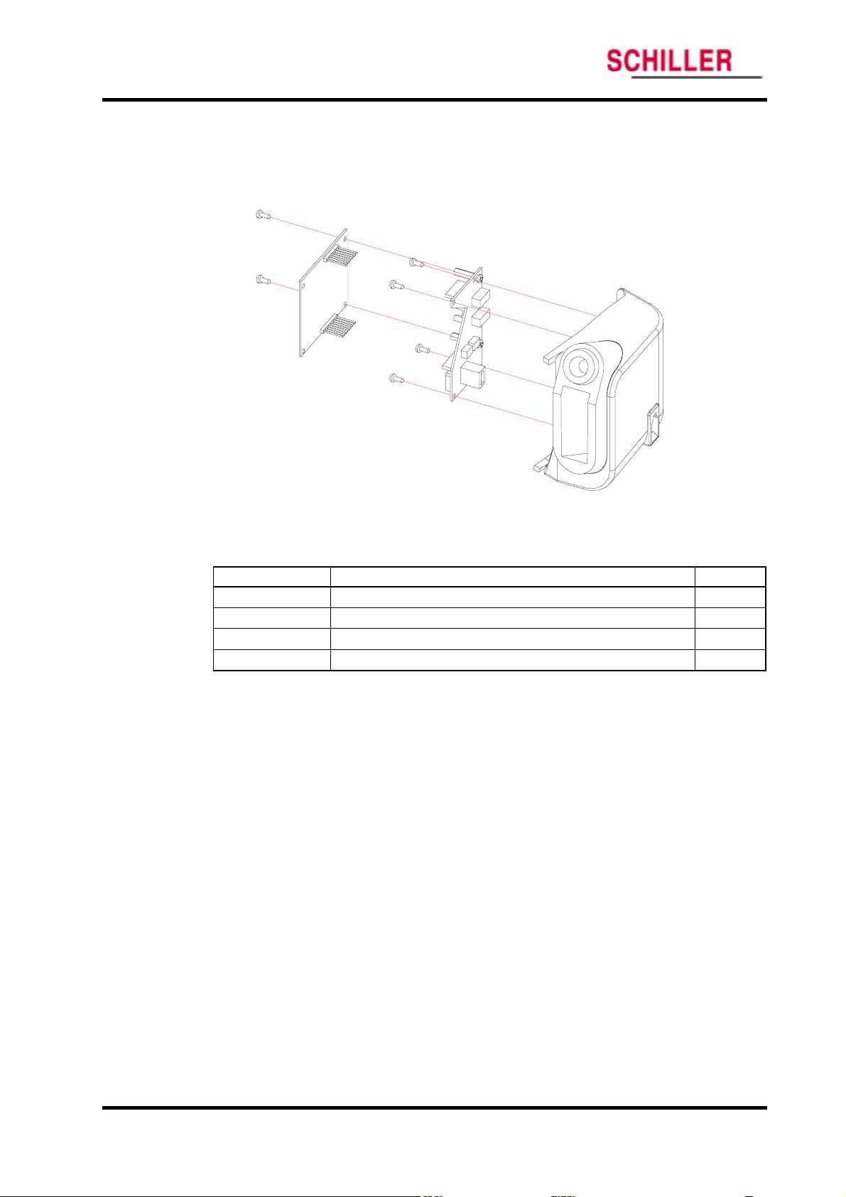
Disassembly Guide
Temperature Case Disassembly
This section describes the items that may be removed on the temperature case assembly.
ARGUS VCM
Figure 25. Temperature Case Disassembly – Temperature Module
Table 19. Part Descriptions – Temperature Module Assembly
Part Codes Descriptions Qty
P1029-0 Temperature BD 1
M0006-0 Temperature module 1
S8007-0 Screw 3 × 6 2
S8071-0 Screw 3 ×8 (tapping) 4
C1.Temperature module disassembly
1. Remove 2 screws (S8007-0) holding Temperature module.
2. Remove Temperature module.
3. Disconnect Temperature wire.
4. Remove 4 screws (S8071-0) fastening Temperature BD.
5. Remove Temperature BD.
54 ARGUS VCM Service Manual
Page 60

ARGUS VCM
Disassembly Guide
Figure 26. Temperature Case Disassembly
Table 20. Part Descriptions – Temperature Case Assembly
Part Codes Descriptions Qty
T0030-0 Temperature case 1
T0031-0 Temperature probe holder 1
S8090-0 Screw 3 × 8 2
S8002-0 Screw 3 × 8 (with washer) 1
C2. Temperature case disassembly
1. After step C1, remove 3 screws holding Temperature probe holder.
2. Remove Temperature probe holder from Temperature case.
ARGUS VCM Service Manual 55
Page 61

Disassembly Guide
ARGUS VCM
Figure 27. ARGUS VCM Exploded View
56 ARGUS VCM Service Manual
Page 62

Spare Parts
Introduction
Obtaining Replacement Parts
Parts List
WARNING: Follow local government ordinances and recycle instructions
regarding disposal or recycling of device components, including batteries.
Introduction
Spare parts, along with part numbers, are shown in Table 21. “Item No.” corresponds to
the circled callout numbers in Figure 8.
Obtaining Replacement Parts
Schiller Technical Service provides technical assistance information and replacement
parts. To obtain replacement parts, contact Schiller. Refer to parts by the part names
and part numbers.
ARGUS VCM Service Manual 57
Page 63

Spare Parts
Parts List
ARGUS VCM
Schiller Technical Service provides technical assistance information and replacement
parts. To obtain replacement parts, contact Schiller. Refer to parts by part numbers and
part names.
Figure 28. ARGUS VCM Exploded View – Spare Parts
58 ARGUS VCM Service Manual
Page 64

ARGUS VCM
Spare Parts
Table 21. ARGUS VCM Parts List
No. Part Code Item
Cases
1 T0024-0 Front case
2 T0025-0 SpO2 connector box
3 T0026-0 Rear case
4 T0027-0 Handle
5 T0029-0 SMPS holder
6 T0030-0 Temperature case
7 T0031-0 Temperature probe holder
Structure Components
8 T8005-0 Front overlay / NST
8 T8006-0 Front overlay / NSTP
8 T8007-0 Front overlay / NS
8 T8008-0 Front overlay / NSP
8 T8009-0 Front overlay / NT
8 T8010-0 Front overlay / NTP
8 T8011-0 Front overlay / N
8 T8012-0 Front overlay / NP
9 T1000-0 Rubber button vertical
10 T1001-0 Rubber button horizontal
11 T4104-0 NIBP cuff hose connector
12 T1005-0 Rubber foot circular
13 T1006-0 Rubber foot oval
14 T1007-0 Temperature connector cover
15 T4107-0 Battery cover
16 GND terminal
17 T4108-0 GND bracket
Electrical Components
18 P1028-0 Main BD
19 P1029-0 Temperature BD
20 M2010-0 SMPS
21 M4019-0 FND module
22 M0005-0 NIBP module
23 M0001-0 SpO2 module
24 M0006-0 Temperature module
25 M4020-0 Printer
26 M6007-0 Lead acid battery
27 E9007-0 Speaker
Harness
- W0107-0 SMPS wire / 8-pin
- W0108-0 Battery wire / 5-pin
- W0109-0 NIBP cable / 24-pin
T4003-0
ARGUS VCM Service Manual 59
Page 65

Spare Parts
ARGUS VCM
No. Part Code Item
- W0110-0 Serial wire / 9-pin
- W0111-0 Temperature wire / 5-pin
- W0112-0 Printer wire / 6-pin
Screws / Spacers
- S8007-0 Screw 3 × 6
- S8090-0 Screw 3 × 8
- S8002-0 Screw 3 × 8 (with washer)
- S8091-0 Screw 3 × 12
- S8092-0 Screw 3 × 16
- S8093-0 Screw 3 × 25
- S8010-0 Screw 2.5 × 6 (flat-head)
- S8070-0 Screw 3 × 8 (flat-head)
- S8094-0 Screw 3 × 8 (small flat-head)
- S8066-0 Screw W 3 × 5 (tapping)
- S8071-0 Screw 3 × 8 (tapping)
- S8096-0 Screw 3 × 25 (tapping)
- S8097-0 Nut M3
60 ARGUS VCM Service Manual
Page 66

Packing For Shipment
General Instructions
Returning the ARGUS VCM
Repacking In Original Carton
Repacking In a Different Carton
General Instructions
To ship the monitor for any reason, follow the instructions in this section.
Pack the monitor carefully. Failure to follow the instructions in this section may result
in loss or damage not covered by the Schiller warranty. If the original shipping carton is
not available, use another suitable carton; North American customers may call Schiller
Technical Services to obtain a shipping carton.
Prior to shipping the monitor, contact your supplier or the Schiller office (Technical
Services Department) for a returned goods authorization (RGA) number. Mark the
shipping carton and any shipping documents with the returned goods authorization
number.
Pack to shipping the monitor, contact your supplier or the Schiller office (Technical
Services Department) for a returned goods authorization number. Mark the shipping
carton and any shipping documents with the returned goods authorization (RGA)
number. Return
Returning the ARGUS VCM
Contact Schiller Technical Services Department for shipping instructions, including a
Returned Goods Authorization (RGA) number. Unless otherwise instructed by Schiller
Technical Services Department, it is not necessary to return other accessory items with
the monitor. Pack
not available, use a suitable carton with appropriate packing material to protect it
during shipping.
Repacking In Original Carton
If available, use the original carton and packing materials. Pack the monitor as follows:
1. Place the monitor and, if necessary, accessory items in original packaging.
ARGUS VCM by any method that provides proof of delivery.
ARGUS VCM in its original shipping carton. If the original carton is
2. Place in shipping carton and seal carton with packaging tape.
3. Label carton with shipping address, return address and RGA number, if applicable.
ARGUS VCM Service Manual 61
Page 67

Packing For Shipment
Repacking In a Different Carton
If the original carton is not available, use the following procedure to pack
1. Place the monitor in a plastic bag.
2. Locate a corrugated cardboard shipping carton with at least 200 pounds per square
inch (psi) bursting strength.
3. Fill the bottom of the carton with at least 2 inches of packing material.
4. Place the bagged unit on the layer of packing material and fill the box completely
with packing material.
5. Seal the carton with packing tape.
6. Label the carton with the shipping address, return address, and RGA number, if
applicable.
ARGUS VCM
ARGUS VCM:
62 ARGUS VCM Service Manual
Page 68

System Processing Description
System Overview
NIBP Processing
SpO2 Processing
Temperature Processing
System Overview
System Block Diagram
MAIN BOARD
TEMPERATURE BOARD
Isolated Area
DC/DC
Temperature
Module
Patient
Connec tor
SMPS /
Battery Charger
PC
PC
D
+12V
T
A
A
Display Driver
Slave MCU
Temperature
Connec tor
Power R egulat ors
(+3.3V / +5V)
Power C onnec tor
DATA
D
A
T
A
NIBP C onnector
NIBP Module
NIBP Pump
DAT A
Button Interface
Main MCU
A
T
A
D
Sound Driver
Speaker
Connec tor
Speaker
DC/DC
PC
PC
DAT
A
DC/DC
DAT
A
DAT A
Printer Connec tor
Printer
Isolated Area
Isolated Area
PC
PC
NurseCall
PC
PC
PC
SpO2Module
Patient
Connec tor
RS232 Driver
Relay
Serial C onnec tor
Figure 29. ARGUS VCM System Block Diagram
ARGUS VCM monitor is a multi-function the monitor for use on adult, pediatric and
neonatal patients; non-invasive blood pressures, arterial oxygen saturation, pulse rate, and
temperature.
ARGUS VCM Service Manual 63
Page 69

System Processing Description
In addition to the monitoring and displaying the status of these physiological parameters,
the instrument performs various microprocessor-programmed analytical functions;
Creating both visual and audible alarm signals when settable limits are violated;
Creating and displaying error codes when conditions are detected that would degrade
or prevent valid measurements;
Creating and reviewing saved data/event;
Providing input to an optional recorder for printout of data.
The monitor is essentially a battery-powered instrument. An internal charging unit is
designed to accept only an AC line voltage.
Unit Description
SMPS
The ARGUS VCM allows the user to connect the monitor to AC power ranging from 100
volts AC to 240 volts AC. AC power enters directly the ARGUS VCM’s Power Supply. A 2amp fuse protects both the “Line” and “Neutral” lines. These user-non-accessible fuses
are located on a fuse socket, which is part of the Power Supply located in the ARGUS
VCM. The ARGUS VCM uses a switch mode power supply (SMPS). This Power Supply
provides the DC power needed to charge the battery and to power the Main Board. The
output of the transformer varies, depending on load and input. High frequency noise
from the AC line and from the Main Board is filtered before passing through the bridge
rectifier. The bridge rectifier provides the DC power used in the ARGUS VCM. The
positive output is 12 volts DC.
Battery Charger
The power supply will charge the battery any time ARGUS VCM is connected to AC
power even if the monitor is not turned on. The voltage applied to the battery is 7.5 ± 0.3
volts DC.
Battery
A lead-acid battery is used in the ARGUS VCM. It is rated at 6 volts DC, 4 amp hours.
When new and fully charged, the battery will operate the monitor for 2 hours. A new
battery will last 10 minutes from the time the low battery alarm is declared until the unit
is shut down due to battery depletion. Recharging the battery to full capacity takes 12
hours. Changing from AC to battery power does not interrupt the normal monitoring
operation of the ARGUS VCM.
Power Regulator
The Power Regulator receives the inputs from the SMPS, the Battery, and generates an
appropriate power rate.
Main MCU
The Main MCU is the heart of the ARGUS VCM. The MCU is a Rabbit 3000. Rabbit 3000
manages each modules to generate signal outputs from data received on the base of the
internal algorithm. The MCU controls sound generation, button check and SMPS
operation. The Rabbit 3000 also communicates with NIBP Module, SpO
Temperature Module, Printer, Display driver and Personal Computer.
ARGUS VCM
2 Module,
64 ARGUS VCM Service Manual
Page 70

ARGUS VCM
System Processing Description
Slave MCU
Slave MCU is Toshiba TMP86PM47U. Slave MCU is mainly used for display driver. Slave
MCU checks on Battery voltage level to transfer the level to Main MCU, and also it
controls SMPS function during Firmware downloading mode.
Button Interface
10 buttons including Power button interfaces Main board directly. Button access controls
the monitor functions including power on/off, operating mode transition, alarm limit
adjustment, alarm silence function, and etc.
Display Driver
Front panel display provides visual patient data and monitor status. At power up, all
indicators are illuminated to allow verification of their proper operation. Display consists
of FND Module. FND module is integrated with Display Drive IC, GM6486. FND module
is able to display red, amber and/or green.
7-segments display patient measurement data, time and/or values. Pulse amplitude
indicator displays in the format of 8-segments. The pulse amplitude indicator illuminates
with each pulse beat. The number of segments illuminated indicates the relative signal
strength of the pulse beat. Indicators are also located on the front panel display. Indicators
are illuminated indicating a function that is active. Functions indicated by the Indicators
are AC/battery status, alarm silence, patient type, NIBP & temperature unit and print
mode.
Sound Driver
Sound frequency generated from Main MCU is transferred to output to the Speaker via
LM386 audio amplifier. The gain of this amplifier changes sound level of volume as a
resistor is adjusted.
NIBP Patient block
NIBP patient block measures NIBP data interfaced with WelchAllyn NIBP module POEM.
More information about NIBP measurement theory is specified in NIBP Processing.
SpO
2 Patient block
SpO2 patient block measures oxygen saturation data and pulse rate interfaced with
Nellcor Oximetry module MP-506. More information about Oximetry theory is specified
in SpO
2 Processing.
Temperature Patient block
Temperature patient block measures Temperature data. interfaced with WelchAllyn
Temperature module SureTemp. More information about Temperature measurement
theory is specified in Temperature Processing.
ARGUS VCM Service Manual 65
Page 71

System Processing Description
NIBP Processing
Overview
The oscillometric technique does not use Korotkoff sounds to determine blood
pressure. The oscillometric technique monitors the changes in cuff pressure caused by
the flow of blood through the artery. The monitor inflates the cuff to a pressure that
occludes the artery. Even when the artery is occluded, the pumping of the heart against
the artery can cause small pressure pulses in the cuff baseline pressure. The monitor
lowers cuff pressure at a controlled rate. As the cuff pressure goes down, blood starts
to flow through the artery. The increasing blood flow causes the amplitude of the
pressure pulses in the cuff to increase. These pressure pulses continue to increase in
amplitude with decreasing cuff pressure until they reach a maximum amplitude at
which point they begin to decrease with decreasing cuff pressure. The cuff pressure at
which the pulse amplitude is the greatest is known as Mean Arterial Pressure(MAP).
The manner in which the pulse amplitudes vary is often referred to as the pulse
envelope. The envelope is an imaginary line that connects the peak of each pressure
pulse and forms an outline. The shape of the envelope is observed by the monitor
using a variety of techniques to determine the diastolic and systolic blood pressure.
ARGUS VCM
MAP
Distole
Systole
Systole
MAP
Distole
Overall Accuracy Discussion
Overall system accuracy shall be determined by considering various influences of the
pressure sensor accuracy, motion artifacts and other artifact created by pressure valve,
technical errors of electrical components, and the origin error of oscillometric method.
The origin error of oscillometric comes from the basic theory of that the MAP is
determined by the pulse. Therefore, there might be an error of the time between two
pulses. In another words, the greatest amplitude point of pulses could not represent
the MAP point exactly.
TIME
TIME
Systole
MAP
Distole
● Oscillometric Response
(Pressure Pulses)
● Cuff Pressure
66 ARGUS VCM Service Manual
Page 72

ARGUS VCM
System Processing Description
On clinical trial perspective, overall system accuracy is not easy to be determined. The
clinical trial test protocols have been tried and have been described in many treatises,
and international standards. So, there are many methods to determine the overall
system accuracy of Automated Sphygmomanometer using the oscillometric method.
But, there are no absolute test protocols to determine the overall system accuracy of the
Automated Sphygmomanometer using oscillometric method. Normally, the Gold
standards of Blood pressure for the reference are the intra-arterial pressure and the
auscultatory method.
The popular standard for the overall system accuracy is AAMI, SP-10 1992; 1996
(Electronic or automated sphygmomanometers).
The main test conditions are as follow:
A. Data comparing the Intra-arterial or the auscultatory by the clinical experts with
the automated sphygmomanometer.
B. For data collection and the data analysis, Bland-Altman Plot is used.
C. On the systolic, diastolic, and MAP, the Deltas of all measurements shall be met
under +/- 5mmHg of mean difference (MD), and +/- 8mmHg of standard deviation
(SD).
(Delta = Intra-arterial or Auscultatory – Automated sphygmomanometer)
SYSTOLIC PRESSURE
Mean difference(MD): 0 mmHg
20
15
10
5
0
-5
-10
-15
Diff ere nce betwee n t est and ref ere nce metho ds (m mHg)
-20
(EXAMPLE) Agreement between test and reference methods for systolic pressure. Hypothetical data
Standard deviation(SD): 6 mmHg
mean + 2 SD
mean
mean - 2 SD
200180160140120100
Average of test and reference methods (mm Hg)
ARGUS VCM Service Manual 67
Page 73

System Processing Description
SpO2 Processing
Overview
Pulse oximetry works by applying a sensor to a pulsating arteriolar vascular bed. The
sensor contains a dual light source and photodetector. Bone, tissue, pigmentation, and
venous vessels normally absorb a constant amount of light over time. The arteriolar bed
normally pulsates and absorbs variable amounts of light during systole and diastole, as
blood volume increases and decreases. The ratio of light absorbed at systole and diastole
is translated into an oxygen saturation measurement (SpO
SpO
2 is dependent upon light from the sensor, excessive ambient light can interfere with
this measurement.
Pulse oximetry is based on two principles: that oxyhemoglobin and deoxyhemoglobin
differ in their absorption of red and infrared light (spectrophotometry), and that the
volume of arterial blood in tissue (and hence, light absorption by that blood) changes
during the pulse (plethysmography). The monitor determines SpO
infrared light into an arteriolar bed and measuring changes in light absorption during
the pulsatile cycle. Red and infrared low-voltage light-emitting diodes (LED) in the
oximetry
detector. Because oxyhemoglobin and deoxyhemoglobin differ in light absorption, the
amount of red and infrared light absorbed by blood is related to hemoglobin oxygen
saturation. To identify the oxygen saturation of arterial hemoglobin, the monitor uses
the pulsatile nature of arterial flow. During systole, a new pulse of arterial blood enters
the vascular bed, and blood volume and light absorption increase. During diastole,
blood volume and light absorption reach their lowest point. The monitor bases its SpO
measurements on the difference between maximum and minimum absorption
(measurements at systole and diastole). By doing so, it focuses on light absorption by
pulsatile arterial blood, eliminating the effects of nonpulsatile absorbers such as tissue,
bone, and venous blood.
Automatic Calibration
Because light absorption by hemoglobin is wavelength dependent and because the mean
wavelength of LEDs varies, an oximeter must know the mean wavelength of the
OXIMAX sensor’s red LED to accurately measure SpO
instrument’s software selects coefficients that are appropriate for the wavelength of that
individual sensor’s red LED; these coefficients are then used to determine SpO
Additionally, to compensate for differences in tissue thickness, the light intensity of the
sensor’s LEDs is adjusted automatically.
Measured versus Calculated Saturation
The measured SpO
calculated from a blood gas partial pressure of oxygen (P
because the calculated saturation was not appropriately corrected for the effects of
variables that shift the relationship between P
partial pressure of carbon dioxide (PC
OXIMAX sensor serve as light sources; a photo diode serves as the photo
2 value from an oximeter may differ from the saturation value that is
ARGUS VCM
2). Because a measurement of
2 by passing red and
2
2. During the monitoring, the
2.
O2). This usually occurs
O2 and saturation: pH, temperature,
O2), 2, 3-DPG, and fetal hemoglobin.
68 ARGUS VCM Service Manual
Page 74

ARGUS VCM
System Processing Description
100
50
Saturation (%)
Functional versus Fractional Saturation
This monitor measures functional saturation — oxygenated hemoglobin expressed as a
percentage of the hemoglobin that can transport oxygen. It does not detect significant
amounts of dysfunctional hemoglobin, such as carboxyhemoglobin or methemoglobin.
In contrast, hemoximeters such as the IL482 report fractional saturation — oxygenated
hemoglobin expressed as a percentage of all measured hemoglobin, including measured
dysfunctional hemoglobin. To compare functional saturation measurements to those
from an instrument that measures fractional saturation, fractional measurements must
be converted as follows:
functional saturation = fractional saturation
100 – (%carboxyhemoglobin + %methemoglobin)
pH
Temperature
PCO2
2,3-DPG
Fetal Hb
pH
Temperature
PCO2
2,3-DPG
0
50 100
PO2 (mmHg)
Oxyhemoglobin Dissociation Curve
× 100
ARGUS VCM Service Manual 69
Page 75

System Processing Description
Temperature Processing
Overview
Patient temperature can be measured via an oral/axillary, rectal, or skin surface probe. A
predictive algorithm in conjunction with the thermistor based thermometer is used for
fast temperature or monitoring temperature.
Predictive temperature
Thermometers that render a temperature reading before steady state is achieved are
classified as predictive thermometers. Predictive thermometers reduce the time required
for measurement by using algorithms to “predict” what the temperature would be if the
probe were left in place until steady state is achieved.
Monitor temperature
A function or mode of an electronic thermometer used to continuously monitor
temperature until it reached the thermal steady state (unchanging). The thermal steady
state is achieved orally in approximately 3 minutes, and axillary in approximately five
minutes.
Measuring Principle
The ARGUS VCM temperature probe utilizes a negative temperature coefficient (NTC)
thermistor and control circuitry in combination with the temperature module’s
predictive algorithm to calculate patient temperatures.
NTC thermistors have a large temperature coefficient of resistance and change in
resistance as temperature changes. This predictable change in resistance is the basis for
predictive thermometry.
The Oral/axillary probe is pre-warmed to approximately 34℃ (94℉). The probe
warming process is a closed loop feedback control system incorporating pulse width
modulation (PWM) control. The probe warmer circuitry is used to heat the probe tip
prior to taking a temperature reading in order to speed the convergence of the
prediction algorithm. A fail safe hardware shut off circuit is included to ensure the
heater will shut down in the event of a software failure.
When the probe is first extracted and colder than 33.9℃, the heater pulse
widths are at a maximum percentage On vs Off to warm the probe quickly.
When the probe reached 33.9℃, the pulse widths narrow to a duty cycle just
enough to maintain temperature.
When the probe is placed in the mouth, the heat supplied by the mouth makes
the pulse widths reduce to zero. This reduction to zero (and probe being at
least up to 33.1 (9℃ 1.6 )℉ triggers the start of the prediction algorithm.
The shape of the rising temperature curve is monitored and the best fit to a curve is
found. When the curve fit is stable, the final predicted temperature is provided.
ARGUS VCM
70 ARGUS VCM Service Manual
Page 76

Page 77

Page 78

Sales and Service information
The SCHILLER sales and service centre network is worldwide. For the
address of your local distributor, contact your nearest SCHILLER subsidiary. In case of difficulty a complete list of all distributors and subsidiaries
is provided on our internet site: http://www.schiller.ch
Sales information can also be obtained from:
Sales@schiller.ch
Argus VCM produced by
Mediana Co.,Ltd.
Adress Headquarter
CHILLER AG Phone: +41 (0)41 766 42 42
S
Algasse 68 Fax: +41 (0)41 761 08 80,
CH-6341 Baar, Switzerland e-mail: sales@schiller.ch
Web: www.schiller.ch
Article Number 2.540041 Rev. a
Issue Date: 10. September 2004
Headquarters: SCHILLER AG, Altgasse 68, CH-6341 Baar, Switzerland, Phone: +41 (0)41 766 42 42, Fax: +41 (0)41 761 08 80, e-mail: sales@schiller.ch
REF: A7055-0
 Loading...