

Page 1
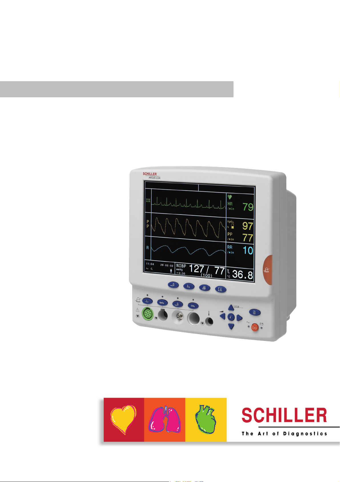
ARGUS LCM
Patient monitor
ARGUS LCM and ARGUS LCM PLUS
Art. no.: 2.510474 rev.: d
Operating Instruction
Page 2

Sales and Service Information
The SCHILLER sales and service centre network is world-wide. For the address
of your local distributor, contact your nearest SCHILLER subsidiary. In case of difficulty a complete list of all distributors and subsidiaries is provided on our internet
site: http://www.schiller.ch.
Sales information can also be obtained from:
sales@schiller.ch
Address Headquarters
SCHILLER AG Phone: +41 (0) 41 766 42 42
Altgasse 68 Fax: +41 (0) 41 761 08 80,
CH-6341 Baar, Switzerland E-mail: sales@schiller.ch
Web: www.schiller.ch
Article no.: 2.510474 rev.: d
Issue date: 10.04.06
Page 3

ARGUS LCM/PLUS
Operating Instruction
Contents
1 Safety notes ..............................................5
1.1 Responsibility of the user ................................................... 5
1.2 Intended use ........................................................................ 5
1.3 Organisational measures..................................................... 5
1.4 Safety-conscious operation ................................................ 6
1.5 Safety facilities ..................................................................... 6
1.6 Operation with other devices .............................................. 6
1.7 Maintenance.......................................................................... 7
1.8 Safety symbols and pictograms ......................................... 8
1.8.1 Symbols used in this user guide ........................................................ 8
1.8.2 Symbols used on the device .............................................................. 9
1.9 Additional terms ................................................................... 9
1.9.1 Implied authorisation.......................................................................... 9
1.9.2 Terms of Warranty ............................................................................. 9
2 Introduction ............................................10
2.1 Version overview ................................................................ 10
2.1.1 ARGUS LCM (basic) from serial number 781.000-781.999............. 10
2.1.2 ARGUS LCM (basic) from serial number 781.1000 and higher ....... 10
2.1.3 ARGUS LCM PLUS (from 780.001and higher)................................ 11
2.2 Functional overview ........................................................... 12
2.2.1 Buttons of the Argus LCM PLUS...................................................... 12
2.2.2 Description of buttons ..................................................................... 13
2.2.3 Description of display ....................................................................... 14
3 Operation ................................................ 15
3.1 Start-up................................................................................ 15
3.1.1 Connecting and power on ................................................................ 15
3.1.2 Battery operation.............................................................................. 15
3.1.3 Operation with external dc voltage................................................... 16
3.2 Switching off and disconnecting from mains.................. 16
3.2.1 Interruption of the mains supply ....................................................... 16
3.3 Inserting printing paper .................................................... 17
3.4 Initial settings ..................................................................... 18
3.4.1 Selecting the language..................................................................... 18
3.4.2 Saving and restoring default values ................................................ 18
3.4.3 Load factory defaults........................................................................ 18
3.4.4 Alarm limit setting............................................................................. 19
3.4.5 Setting loudness of audible alarm and QRS sound ......................... 20
3.5 Trend or alarm display ....................................................... 21
3.6 Display of additional leads ................................................ 21
Art. no.: 2.510474 rev.: d
3.7 Procedure in case of an alarm .......................................... 22
3.7.1 Display of alarms.............................................................................. 22
3.7.2 Switching off an alarm...................................................................... 22
3.7.3 Suppressing/acknowledging an audible alarm................................. 23
3.7.4 Preventive alarm suppression.......................................................... 24
3.7.5 Overview of physiological alarms..................................................... 24
Page 1
Page 4

ARGUS LCM/PLUS
4 Start monitoring .....................................25
4.1 Connecting the cables for monitoring.............................. 25
4.2 ECG monitoring .................................................................. 25
4.2.1 RRi monitoring with HF-ECG cable ................................................. 25
4.2.2 Pacemaker monitoring..................................................................... 26
4.2.3 Pacemaker monitoring with HF-ECG cable ..................................... 26
4.3 NIBP monitoring ................................................................. 27
4.4 SPO
monitoring................................................................. 28
2
4.5 IBP monitoring .................................................................... 29
4.5.1 Preparing IBP measurement............................................................ 29
4.5.2 IBP calibration.................................................................................. 30
4.6 CO2 monitoring ................................................................... 30
4.7 Temperature monitoring .................................................... 30
5 Maintenance ............................................31
5.1 Maintenance interval .......................................................... 31
5.1.1 Visual unit check.............................................................................. 31
5.1.2 Button test........................................................................................ 31
5.2 Maintenance interval for the battery ................................. 32
5.2.1 Charging the battery ........................................................................ 32
5.2.2 Battery disposal ............................................................................... 32
5.3 Changing the fuse and mains voltage .............................. 33
5.4 Cleaning the device, cable and sensors........................... 34
5.4.1 Cleaning the device, cables and sensors ........................................ 34
5.5 Zero and two point CO2 calibration .................................. 35
5.5.1 Starting the zero point calibration .................................................... 35
5.5.2 Starting the two point calibration...................................................... 35
5.6 Trouble shooting ................................................................ 36
5.6.1 Accessories and disposables........................................................... 37
6 Technical Data ........................................38
6.1 System data......................................................................... 38
6.2 Technical data - measured values .................................... 40
6.2.1 ECG ................................................................................................. 40
6.2.2 Respiration....................................................................................... 40
6.2.3 Temperature .................................................................................... 41
6.2.4 NIBP - non-invasive blood pressure ................................................ 41
6.2.5 IBP - invasive blood pressure .......................................................... 41
6.2.6 SpO
6.2.7 etCO
- pulsoximetry ........................................................................ 42
2
- capnography....................................................................... 42
2
7 Appendix .................................................43
7.1 Settings menu ..................................................................... 43
7.1.1 Main menu ....................................................................................... 43
7.1.2 Special menu “About+” .................................................................... 44
7.2 Factory settings .................................................................. 45
7.3 Connecting the ECG patient cable ................................... 46
7.3.1 3-leads cable for children and neonates.......................................... 46
7.3.2 3-lead cable for respiration .............................................................. 46
7.3.3 3-lead cable for adults...................................................................... 46
7.3.4 3p-lead cable ................................................................................... 48
Art. no.: 2.510474 rev.: d
Page 2
Page 5

ARGUS LCM/PLUS
Operating Instruction
7.3.5 Three- and five-lead cables for adults and children ......................... 48
7.3.6 10-lead ECG patient cable............................................................... 49
7.3.7 Electrodes identification and colour code IEC/AHA ......................... 50
7.4 CO2 settings........................................................................ 51
7.4.1 Description of CO2 parameters........................................................ 51
7.4.2 Compensation settings..................................................................... 51
7.4.3 Combination of N
7.4.4 Environmental pressure compensation............................................ 52
O and O2 compensation .................................... 52
2
8 Index ........................................................ 53
Art. no.: 2.510474 rev.: d
Page 3
Page 6

ARGUS LCM/PLUS
Page 4
Art. no.: 2.510474 rev.: d
Page 7
ARGUS LCM/PLUS
Safety notes 1
Operating Instruction Responsibility of the user 1.1
1 Safety notes
1.1 Responsibility of the user
V This device must only be used by qualified doctors or trained medical personnel
under their direct supervision.
V The numerical and graphical results and any interpretation given must be exam-
ined with respect to the overall clinical condition of the patient and the general recorded data quality.
V The indications given by this equipment are not a substitute for regular checking
of vital functions.
V Specify the competencies of the personnel for operation and repair.
V Ensure that the personnel have read and understood these operating instructions
and in particular this chapter “safety notes".
V Have damaged or missing components replaced immediately.
V The operator is responsible for compliance with all applicable accident prevention
and safety regulations.
1.2 Intended use
V The ARGUS LCM/PLUS is a patient monitoring device used for the measuring of
, CO
the parameters of a patient, including ECG, SpO
sure, temperature and respiration.
V The system is suitable for internal hospital transport.
V There is no danger for patients with pacemaker.
V The device is only intended for single patient use.
V Only operate the device in accordance with the specified technical data.
V The system is not designed for sterile use nor is it designed for outdoor use.
V Do not use this unit in areas where there is any danger of explosion or in the pres-
ence of flammable gases such as anaesthetic agents.
V This unit is CF classified. It is defibrillation protected only when the
SCHILLER original patient cable is used. However, as a safety precaution when
possible, remove electrodes before defibrillation.
V This product is not designed for direct cardiac application.
non invasive blood pres-
2
2,
1.3 Organisational measures
V Before using the unit, ensure that an introduction regarding the unit functions and
the safety precautions has been provided by a medical product representative.
V Keep these operating instructions in an accessible place for reference when re-
quired. Make sure that they are always complete and legible.
V Observe the operating instructions and maintenance instructions.
Art. no.: 2.510474 rev.: d
V These operating instructions do not override any statutory or local regulations, or
procedures for the prevention of accidents and environmental protection.
Page 5
Page 8
1 Safety notes
1.4 Safety-conscious operation
1.4 Safety-conscious operation
1.5 Safety facilities
ARGUS LCM/PLUS
V Make sure that the staff has read and understood the operating instructions - par-
ticularly the "Safety Notes" chapter.
V Position the device so that there is no possibility of it falling on the patient or floor.
V Do not touch the unit casing during defibrillation.
V To grant the patient's safety, it must be ensured that neither the electrodes, in-
cluding the neutral electrode, nor the patient, or persons touching the patient,
come into contact with conducting objects (e.g. RS-232 interface - see Fig. 3.1 on
page 15), even if these are earthed.
V Immediately report any changes that impair safety (including operating behav-
iour) to the person responsible.
V Do not place any liquids on the unit. If liquid should be spilled over the device,
immediately disconnect the device from the mains and wipe it. The device must
be serviced before reusing.
V Operating the device without the correctly rated fuse, or with defective cables,
constitutes a danger to life. Therefore:
– Do not operate the unit if the earth connection is suspect or if the mains lead is
damaged or suspected of being damaged.
– Damaged cable connections and connectors must be replaced immediately.
– The electrical safety devices, such as fuses, must not be modified.
– Ruptured fuses must only be replaced with the same type and rating as the orig-
inal.
1.6 Operation with other devices
V Use only accessories and other parts recommended or supplied by SCHILLER
AG. Use of other than recommended or supplied parts may result in injury, inaccurate information and/or damage to the unit.
V Ancillary equipment connected to the analogue and/or digital interfaces must be
certified according to the respective IEC standards (e.g. IEC/EN 60950 for data
processing equipment and IEC/EN 60601-1 for medical equipment). Furthermore
all configurations shall comply with the valid version of the system standard IEC/
EN 60601-1-1. Everybody who connects additional equipment to the signal input
part or signal output part configures a medical system, and is therefore responsible that the system complies with the requirements of the valid version of the system standard IEC/EN 60601-1-1. If in doubt, consult the technical service department or your local representative.
V Any other equipment used with the patient must use the same common earth as
the ARGUS LCM.
V Precautions must be observed when using high frequency devices. Use the fre-
quency SCHILLER patient cable to avoid possible signal interference during ECG
acquisition.
V There is no danger when using the ECG unit simultaneously with electrical stim-
ulation equipment. However, the stimulation units should only be used at a sufficient distance from the electrodes. If in doubt, the patient should be disconnected
from the monitor.
V If the patient cable should become defective after defibrillation, a lead-off indica-
tion is displayed in the upper right part of the screen and an audible alarm is issued.
Art. no.: 2.510474 rev.: d
Page 6
Page 9

ARGUS LCM/PLUS
Safety notes 1
Operating Instruction Maintenance 1.7
1.7 Maintenance
V Danger of electric shock! Do not open the device. No serviceable parts inside.
Servicing may only be carried out by a qualified technician authorised by Schiller
AG.
V Before cleaning and to isolate the mains power supply, switch the unit off and dis-
connect it from the mains by removing the plug.
V Do not use high temperature sterilisation processes
(such as autoclaving). Do not use E-beam or gamma radiation sterilisation.
V Do not use solvent or abrasive cleaners on either the unit or cable assemblies.
V Do not, under any circumstances, immerse the unit or cable assemblies in liquid.
Art. no.: 2.510474 rev.: d
Page 7
Page 10
1 Safety notes
1.8 Safety symbols and pictograms
1.8 Safety symbols and pictograms
1.8.1 Symbols used in this user guide
ARGUS LCM/PLUS
The safety level is classified according ANSI Z535.4. The following overview shows
the safety symbols and pictograms used in this manual
For a direct danger which could lead to severe personal injury or death.
For a possibly dangerous situation, which could lead to heavy bodily injury or death.
For a possibly dangerous situation which could lead to personal injury. This symbol
is also used to indicate possible damage to property.
For general safety notes as listed in this chapter.
Used for electrical dangers, warnings and other notes in regarding operation with
electricity.
NOTE For possibly dangerous situations, which could lead to damages to property
or system failure or IMPORTANT for helpful user information.
Reference to other guidelines
Page 8
Art. no.: 2.510474 rev.: d
Page 11
ARGUS LCM/PLUS
Safety notes 1
Operating Instruction Additional terms 1.9
1.8.2 Symbols used on the device
Potential equalisation
CF symbol. This unit is classified safe for internal and external use. However, It is
only defibrillation protected when used with the original SCHILLER patient cable!
The unit/component can be recycled.
Notified body of the CE certification (TÜV P.S.)
Note: Follow the instructions in the documentation.
1.9 Additional terms
1.9.1 Implied authorisation
Possession or purchase of this device does not convey any express or implied license to use the device with replacement parts which would alone, or in combination with this device, fall within the scope of one or more patents relating to this device.
1.9.2 Terms of Warranty
Your SCHILLER ARGUS LCM/PLUS is warranted against defects in material and
manufacture for the duration of one year (as from date of purchase). Excluded from
this guarantee is damage caused by an accident or as a result of improper handling.
The warranty entitles free replacement of the defective part. Any liability for subsequent damage is excluded. The warranty is void if unauthorised or unqualified persons attempt to make repairs.
In case of a defect, send the apparatus to your dealer or directly to the manufacturer.
The manufacturer can only be held responsible for the safety, reliability, and performance of the apparatus if:
• assembly operations, extensions, readjustments, modifications, or repairs are carried out by persons authorised by him, and
• the ARGUS LCM/PLUS and approved attached equipment is used in accordance
with the manufacturer's instructions.
There are no express or implied warranties which extend beyond the warranties
hereinabove set forth. SCHILLER makes no warranty of merchantability or fitness for
a particular purpose with respect to the product or parts thereof.
Art. no.: 2.510474 rev.: d
Page 9
Page 12

2 Introduction
2.1 Version overview
ARGUS LCM/PLUS
2 Introduction
The ARGUS LCM/PLUS (Low Weight and Compact Monitor) is a flexible patient
monitoring device for the comprehensive monitoring of vital parameters in adults,
children and neonates.
Mains power supply (115/230 VAC) is used for stationary use. The LCM also provides full vital data monitoring during transport with the built in battery (one hour),
or using a DC voltage supply (11 - 30 VDC).
2.1 Version overview
2.1.1 ARGUS LCM (basic) from serial number 781.000-781.999
The following table shows the equipment of the ARGUS LCM. This basic device cannot be upgraded.
ARGUS LCM ECG SpO
Basic device Only with 3 leads/display one lead (II) x x
Options: printer, additional battery (can be updated in the field)
2
NIBP
2.1.2 ARGUS LCM (basic) from serial number 781.1000 and higher
The ARGUS LCM BASIC with the microprocessor MK19-11 has a new ECG amplifier
(3p). It is now possible to to display 6 leads with a 3p-lead cable. The 3p-lead cable
is marked with a black connector housing instead of green.
This works only with software 1.24 and higher.
ARGUS LCM version
Axxxx1x
B x x x x 1x x
Dxxxx1xx
E x x x x x x
a
Monitoring amplifier only with 3p- and 5 lead cable (6 or 7 lead display)
Options for all versions: printer, additional battery and nurse call or vehicle power supply
Version A can be updated with etCO
Version B/C/D/E can be updated with printer and additional battery
a
ECG
SpO2 NIBP Respiration Temperature etCO
module, printer and additional battery.
2
IBP
2
Page 10
Art. no.: 2.510474 rev.: d
Page 13

ARGUS LCM/PLUS
Introduction 2
Operating Instruction Version overview 2.1
2.1.3 ARGUS LCM PLUS (from 780.001and higher)
ARGUS LCM PLUS version
a
ECG
SpO2 NIBP Respiration Temperature etCO2IBP
AxxxX1x
B x x x x 1x x
Dxxxx1xx
E x x x x x x
a
Diagnostic amplifier only with 3- or 5- or 10 lead cable (1- or 7- or 12 lead display)
Options for all versions: printer, additional battery and nurse call or vehicle power supply
Version A can be upgrade with etCO
module, printer and additional battery.
2
Version B/C/D/E can be upgrade with printer and additional battery
Art. no.: 2.510474 rev.: d
Page 11
Page 14
2 Introduction
2.2 Functional overview
ARGUS LCM/PLUS
2.2 Functional overview
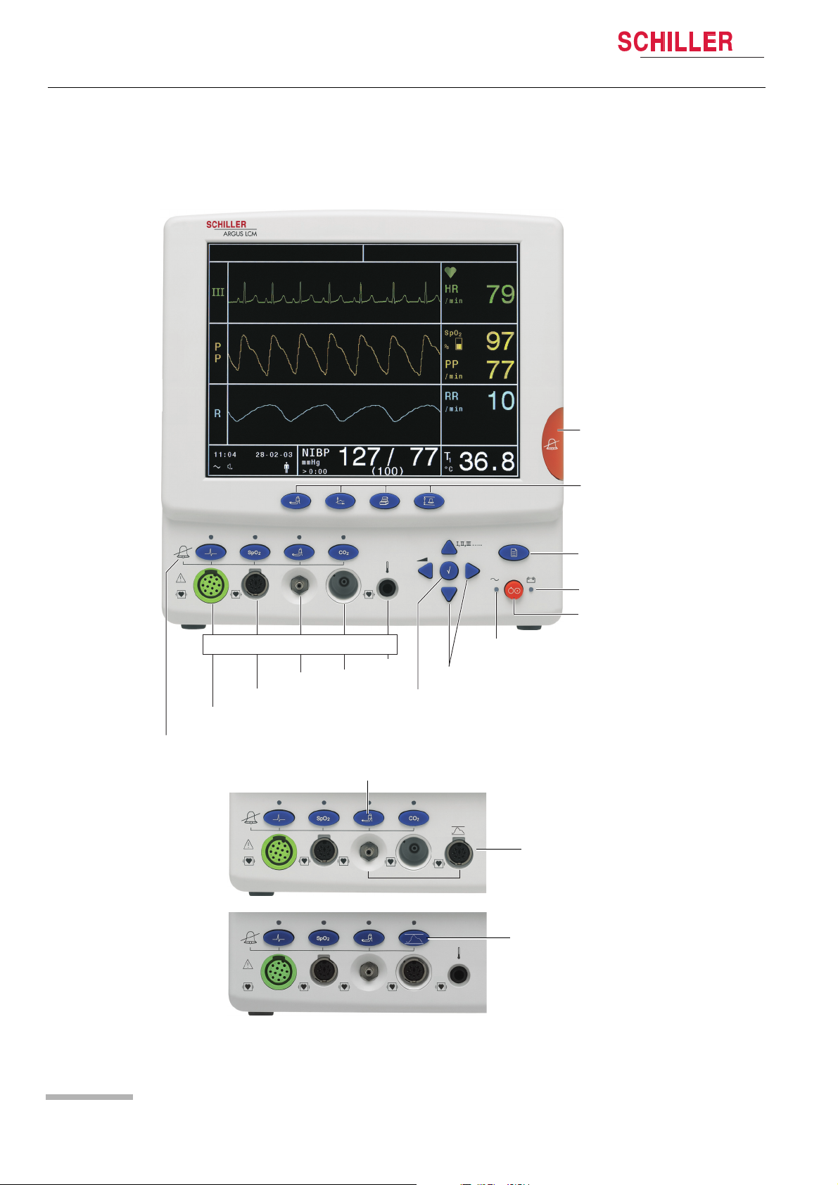
2.2.1 Buttons of the Argus LCM PLUS
i
Audible Alarm
suppress/acknowledge
ECG
Alarm OFF
This is the LCM plus
version E.
1
2
Patient connections
CO
IBP
SPO
NIBP
2
Access to the menu IBP and NIBP alarm
on/off and IBP calibration.
Direct buttons for :
1. NIBP s
tart/stop
2. Trend display
3
4
3. Print
4. Setting alarm limits
Menu access button
LED indicating battery
operation
LCM ON/OFF button
LED indicating main supply operation
°C/°F
2/
Navigation buttons down/up, /leftright
Program and enter button
IBP connection instead of Temperature
This is the LCM plus
version D.
Page 12
Fig. 2.1 ARGUS LCM front view
IBP connection instead of CO
2
Art. no.: 2.510474 rev.: d
Page 15
ARGUS LCM/PLUS
Introduction 2
Operating Instruction Functional overview 2.2
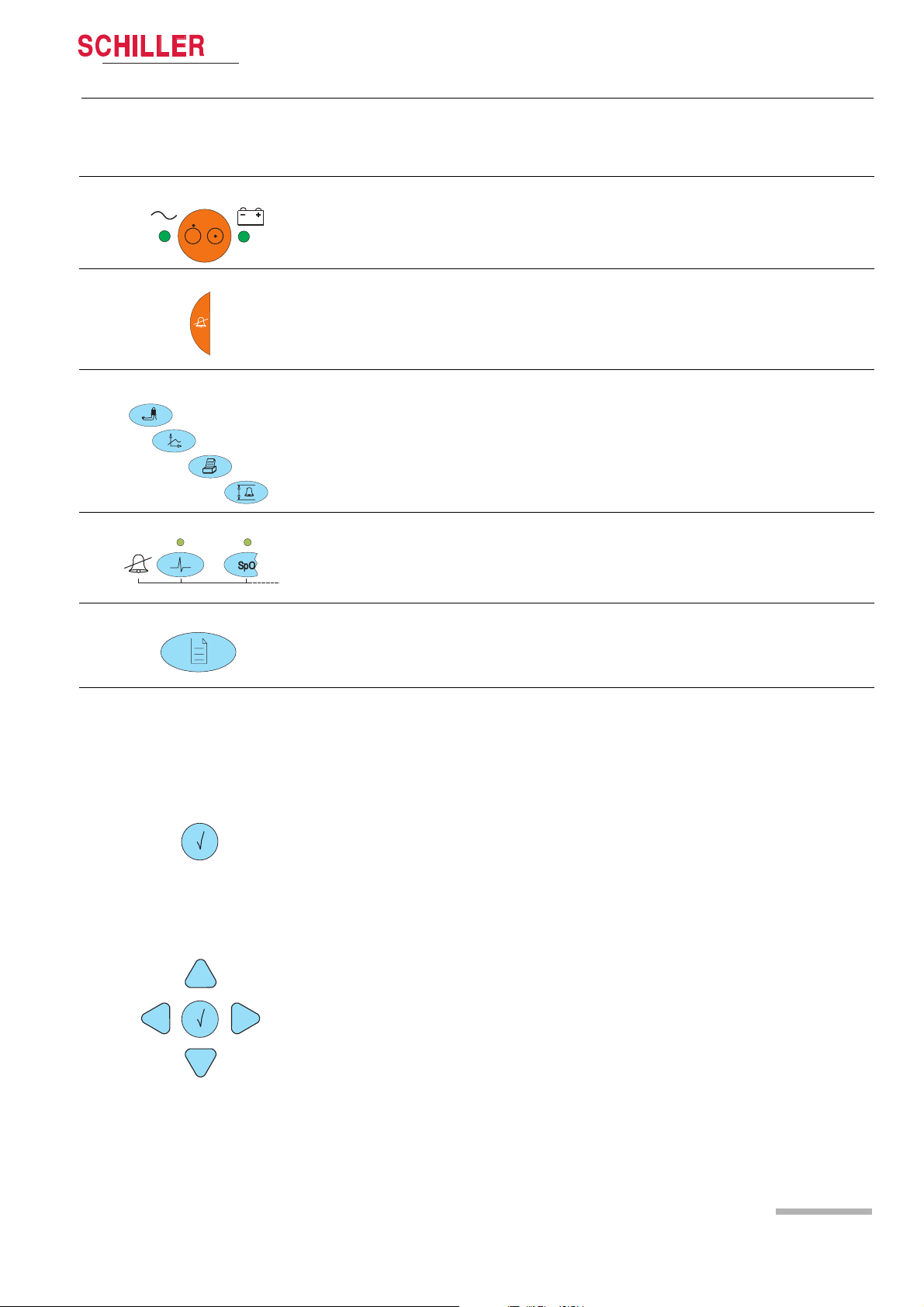
2.2.2 Description of buttons
ON/OFF
The LED indicates if the LCM is running from mains power or battery.
Button for suppression/acknowledgement of audible alarms
The alarm can be suppressed or acknowledged in two ways. This is defined in set-
tings About+/Alarm setup menu.
See detailed description in paragraph 3.7.3
Direct buttons for:
(1) NIBP start/stop or, if pressed for 2 s, switch between auto and manual
(2) Trend and alarm displays
(3) Printout of the current display
(4) Alarm limit settings
Art. no.: 2.510474 rev.: d
Enter
Navigation
Alarm off
These buttons disable alarms of the individual parameters. Acknowledgement is
displayed on the top left e.g. ECG Alarm OFF. The LED above the corresponding
button is lit (for details refer to section 3.7.4).
Menu access
Opens the main menu. Navigate through the menus with the right/left buttons.
Press the menu button to again leave the menu.
The navigation and enter buttons have different functions dependent on operating
mode:
Normal single lead display:
Pressing the enter button shows the first 3 leads instead of the single lead display.
By pressing the up/down buttons, the next lead, or lead group is displayed.
Press the left button to adjust the loudness of the audible alarm and the QRS signal.
Programming mode:
1. Activating the programming mode with the menu button.
2. Selecting the menu with the left/right buttons.
3. Selecting a value with the up/down buttons.
4. Press the enter button.
5. Change a value using the up/down buttons.
6. Retrieve a value by pressing enter.
Trend display mode:
Activate the trend display mode with the trend display button.
Use the
left/right buttons to move forward/backward in the trend display.
Use the trend button to toggle between the trend display, alarm display and normal
monitor display.
Page 13
Page 16
2 Introduction
2.2 Functional overview
ARGUS LCM/PLUS
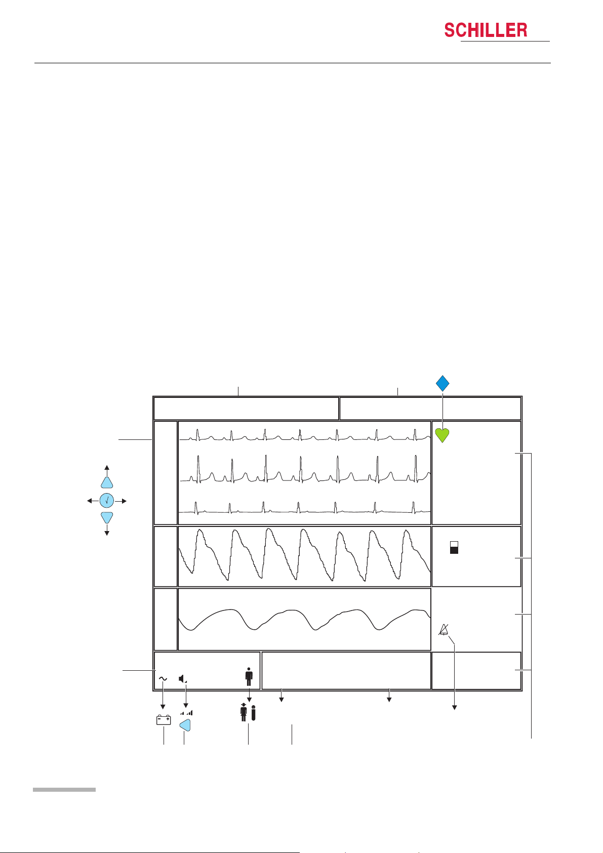
2.2.3 Description of display
Alarms
(1) Status field for physiological alarms
(2) Status field for technical alarms
Curve field
(3) 1 or 3 channel leads display. With enter display 1 or 3 leads, with
up/down select the following/previous lead/lead group.
System status field
(4) System status field
(5) Symbol for battery operation.
(6) Loudness (3-step) for alarm- and QRS-sound. Adjust with left button.
(7) Symbol of the selected patient type.
Blood pressure
(8) < 0:12 A = remaining time (h/min) to the next automatic blood pressure meas-
urement.
> 0:12 = Time since the last manual blood pressure measurement
Remark: During blood pressure measuring the actual system pressure in mmHg
will be displayed.
Measurement field
(9) Various displayed values e.g. HR, Sp02, IBP, CO2, RRi, temperature.
I
aVR, III,...
3
I,II, …
4
1
Alarm HR Low ECG lead off
I
II
I
II
III
III
P
P
R
11 :04 28-10-04
NIBP
mmHg
<0:12A
>0:12
127/77
SYS/DIA
2
(100
(MAP)
PM detection
HR
/ min
PM ON
SpO
%
PP
/ min
RRi
/ min
T
1
)
°C
RRi Alarm
switch off
60
2
98
60
10
36.8
Art. no.: 2.510474 rev.: d
Page 14
56
78
9
Page 17
ARGUS LCM/PLUS
Operation 3
Operating Instruction Start-up 3.1
3Operation
3.1 Start-up
V Danger of electrical shock. Do not operate the unit if the earth connection is sus-
pect or if the mains lead is damaged or suspected of being damaged.
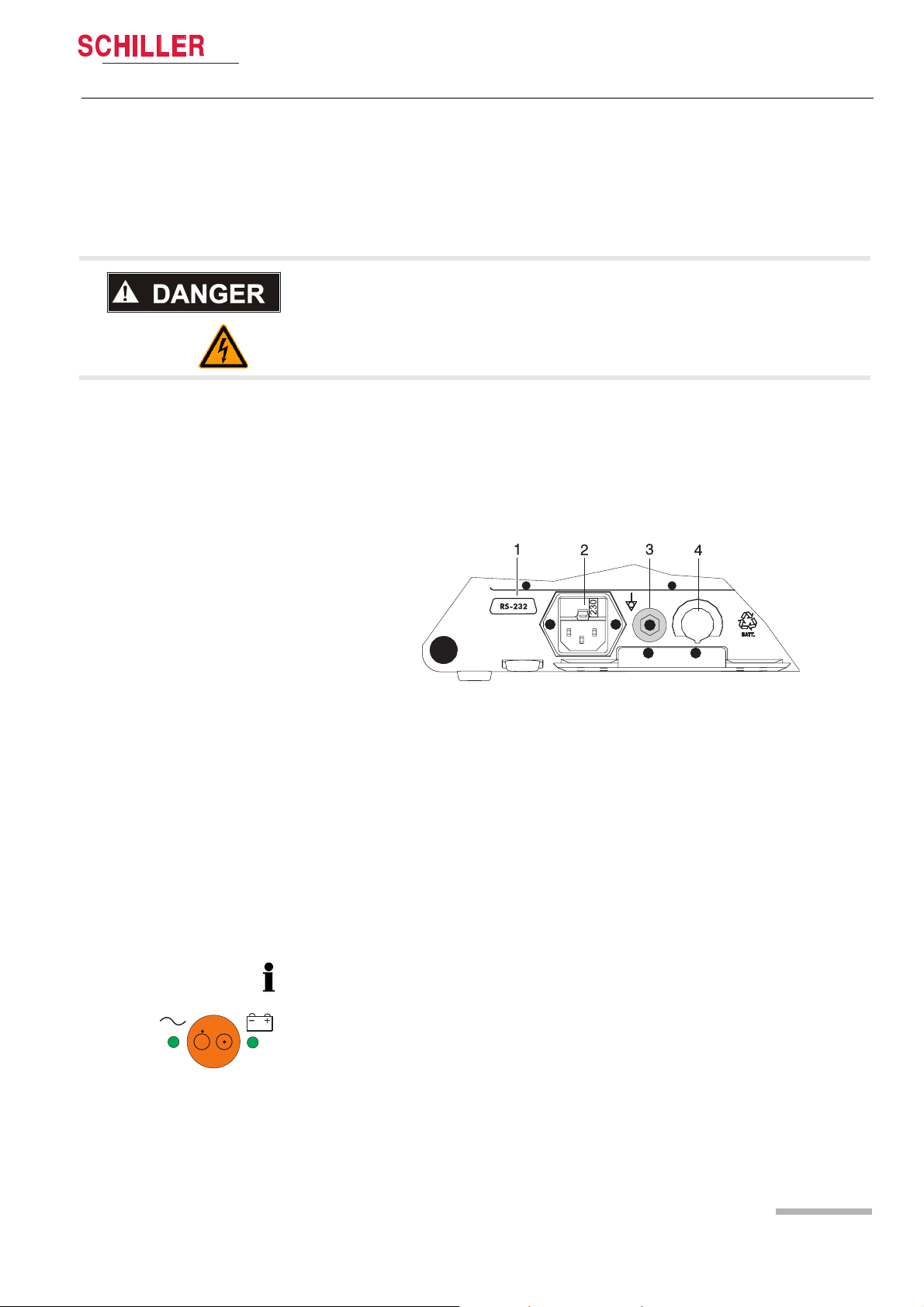
3.1.1 Connecting and power on
(1) RS-232
(2) Mains connection (100 -115 or 220 -240 VAC)
(3) Potential equalisation
(4) Nurse call or DC in 11 - 30 VDC (option)
Fig. 3.1 ARGUS LCM back panel
1. Voltage setting (2) 115 or 230 V. Refer to chapter 5.3 for the mains voltage. Connect the power cable at the rear of the unit (2).
2. Connect the potential equalisation cable (3) to the central potential equalisation
socket.
3. Press the on/off button.
4. Check that all LEDs flash shortly and there is a
beep on start-up.
5. Check the settings according to sections 3.4 and 7.1.
3.1.2 Battery operation
Important
The Battery operation is indicated by the LED below the battery symbol.
When the battery charge is low, the alarm message Battery low appears or
Art. no.: 2.510474 rev.: d
1
– the LED (1) blinks
– the Battery symbol in the bottom left display field blinks
for Battery recharging refer to chapter 5.2
Page 15
Page 18

3Operation
3.2 Switching off and disconnecting from mains
3.1.3 Operation with external dc voltage
Important
Before initial operation with external dc voltage, check voltage supply. (The voltage
must be in the range of 11-30 VDC). On connection, make sure that the polarity is
correct.
3.2 Switching off and disconnecting from mains
1. Press the on/off button. A dialogue window appears.
2. Select with the left button YES and confirm the selection with the enter button.
3. Remove the mains cable from the mains supply socket (2) (see Fig. 3.1) to isolate
the device from the mains.
Important
If no dialogue window appears, it is possible to switch off the device by keeping the
On/Off button pressed for 10 seconds.
ARGUS LCM/PLUS
3.2.1 Interruption of the mains supply
If the mains supply is interrupted, the device automatically switches over to battery
operation. The user settings are maintained. These settings can be saved in the
menu About+/Software.
Page 16
Art. no.: 2.510474 rev.: d
Page 19

ARGUS LCM/PLUS
1
Operation 3
Operating Instruction Inserting printing paper 3.3
3.3 Inserting printing paper
Important
The device is delivered without printing paper installed. Only use original SCHILLER printing paper. The thermo-paper is sensitive to heat, humidity and chemical vapours. Store the paper in a cool and dry area.
1. Press the locking catch (1) upwards. The printer door opens downward
2. Insert paper and pull it up. Be sure that the paper lies behind the cover (2).
3. Close the cover. Be sure that the paper lies exactly between the rails (3).
2
3
Art. no.: 2.510474 rev.: d
Page 17
Page 20

3Operation
3.4 Initial settings
ARGUS LCM/PLUS
3.4 Initial settings
This chapter details the most important and typical programming sequences.
V Only authorised personnel, trained in the operation of this device, are permitted
to do the setups in the following menu.
The extended menu is displayed by pressing the following button combination:
Press ; select About; press and then .
3.4.1 Selecting the language
1. Open the menu About/Device.
2. Confirm with the enter button.
3. Press the down button and select the language.
4. Confirm with the enter button.
5. Press right/left to move to the next menu and continue with more setups.
6. Save the user settings. Open the Software panel, select Save as Default and
confirm with the enter button.
7. Return to the normal display mode by pressing the menu button.
For system settings, see detailed list in the sections 7.1.1and 7.1.2.
3.4.2 Saving and restoring default values
Changed values can be saved permanently and restored. See section 7.1.2.
1. Open the About+ panel and select Device.
2. Select Save as Default or Restore Defaults and confirm with
enter. The default values will then be saved or restored.
3. Press the menu button to exit the programming mode.
3.4.3 Load factory defaults
When the factory defaults are loaded, the system language will be German.
The SCHILLER factory defaults are listed in section 7.2. When you load these defaults, they will overwrite the user settings.
1. Open the About+ panel and select Device.
2. Select Factory Defaults and confirm with the enter button. The factory defaults
will be loaded.
3. Press the menu button to exit the programming mode.
Art. no.: 2.510474 rev.: d
Page 18
Page 21

ARGUS LCM/PLUS
Operation 3
Operating Instruction Initial settings 3.4
3.4.4 Alarm limit setting
All alarm limits are reset to the default or user specific system settings after switching the unit off/on, if they have not been stored as default. (see menu About+/Soft-
ware)
1. Press alarm limit button.
2. Press up/down or left/right buttons to select an alarm parameter and confirm
with enter. The entry field appears blue.
3. Press up/down to change the value and confirm with the enter button.
4. Press the up/down or left/right buttons to select other parameters or press the
alarm limit button to exit the menu.
The following table gives the default alarm limits settings for adults. A changed value can be stored as default in the menu About+/Software.
The factory defaults are listed in the sections 7.1 and 7.2..
Alarm Low High Unit
a
Prio.
b
Print
HR 50 140 /min High Off
ASYS - 2 s High Off
c
RRi
c
APNi
SpO
2
8 35 min Low Off
- 25 s High Off
90 101 % Low Off
PP 50 140 min High Off
SYS 100 140 mmHg Low Off
DIA 40 95 mmHg Low Off
MAD 70 140 mmHg Low Off
Ps 95 180 mmHg Low Off
Pm 50 100 mmHg Low Off
Pd 40 100 mmHg Low Off
eCO
CO2 i
2
35 45 mmHg Low Off
0 2 mmHg Low Off
RRc 8 35 /min Low Off
APNc - 25 s High Off
a. "High" priority = audible signal with 2 x 5 impulses.
"Low" priority = audible signal with 1 x 2 impulses and 20 s pauses between the
impulse sequences.
Art. no.: 2.510474 rev.: d
b. Print "On" = Default printout containing a warning message when the min./max.
value is exceeded.
c. If the RRi alarm option is Off in the ECG settings panel, the "Low" and "High" val-
ues for RRi and APNi will be "Off".
Page 19
Page 22

3Operation
3.4 Initial settings
ARGUS LCM/PLUS
Printing alarm limits
1. Press the alarm limit button.
2. Press the print button. The displayed table is printed.
3.4.5 Setting loudness of audible alarm and QRS sound
1. Select normal monitor mode. Press menu if in programming mode or trend if in
trend display.
2. Press the left button to adjust the loudness. The pictogram in the status display
on the bottom left shows the current setting.
Page 20
Art. no.: 2.510474 rev.: d
Page 23

ARGUS LCM/PLUS
Operation 3
Operating Instruction Trend or alarm display 3.5
3.5 Trend or alarm display
The trend values are measured every minute and additionally on every manual
NIBP measurement. The trends can be displayed in graphical or tabular form for all
parameters over 24 hours.
The display interval for the table can be selected in the menu About+/Trend. The
displayed trend table or not acknowledged alarms can be printed out by pressing
the print button. The displayed graph cannot be printed.
Table display
1. Press the trend button. The trend will be displayed in a table in 1, 5 ,15, 30, 60,
120 or 240 minute intervals. Change the displayed interval using the up/down
button. Move the display forward/backward on the time axis using the left/right
button.
Graph display (cannot be printed)
2. To display the graph, press the trend button once again. The graph's time frame
corresponds to 3 hours. Display the next 3 h by pressing the up/down button.
Move the cursor on the top right corner using the right/left button to display the
exact measured values for the selected position on the right. The cursor can be
positioned on the NIBP value by pressing ENTER .
Display of not acknowledged alarms
3. To display the last twelve not acknowledged alarms, press the trend button a third
time.
3.6 Display of additional leads
The basic LCM basic serial number 0-999 can only display one lead.
1. Select the normal monitor mode. Press menu if in programming mode or trend
if in trend display.
2. Press the enter button to switch between the normal display mode containing
one lead and the 3-lead display.
3. By pressing the up/down buttons, the next leads are displayed.
Art. no.: 2.510474 rev.: d
Page 21
Page 24

3Operation
I
3.7 Procedure in case of an alarm
3.7 Procedure in case of an alarm
3.7.1 Display of alarms
3.7.2 Switching off an alarm
ARGUS LCM/PLUS
During initial switching on
The alarms are suppressed for a defined time (programmable in the menu About+/
Alarm. Alarm suppr. time standard is 3 minutes)
The message Alarm suppressed 3:00 appears.
During monitoring
There are two alarms:
• Technical alarm, displayed in the alarm status field on the top right.
In the case of a technical alarm, an audible alarm sounds and the measurement
field for the respective value flashes.
• Physiological alarms, displayed in the alarm status field on the top left.
In the case of a physiological alarm, an acoustic alarm sounds and the measurement field for the respective value flashes.
Each alarm off function is password protected. Read carefully the following warning
and information:
V When the acoustic alarm is switched off, the patient acoustic physiological
alarms are silenced and suppressed indefinitely. Use this function only if disconnecting a sensor from the patient for a long period of time.
• When the alarm off button is pressed, the audible alarm for the respective parameter is suppressed. This is indicated by the LED above the button and a message
on the monitor, e.g. Alarm ECG OFF. If an alarm occurs as long as the alarm off
button is pressed, a visual alarm is displayed in the respective measurement field.
• With the LCM plus version E the access to the NIBP and IBP alarm off function will
be executed by the NIBP alarm button. A menu with blood pressure alarm off (common for NIBP and IBP) and IBP calibration function appears.
BP Alarm On/Off
Connect zero mmHg
Start IBP calibration
End / Escape
Page 22
Enter Password
Press [Enter] to cancel
Entering alarm OFF password
1. Press the desired alarm off button. The password dialog appears.
2. Press following button to enter the password:
, , ,
1. The password protection can be disabled in the special menu see chapter 7.1.2
page 44
I,II, II
Art. no.: 2.510474 rev.: d
Page 25

ARGUS LCM/PLUS
Operation 3
Operating Instruction Procedure in case of an alarm 3.7
3.7.3 Suppressing/acknowledging an audible alarm
There are two ways to proceed in the case of an alarm. The procedure depends on
the set alarm stop mode (On/Off) and the alarm suppression time in the menu
About+/Alarm:
(1) Alarm stop off (suppression)
This function suppresses an audible alarm for a defined period of time. However, the
flashing measurement field (red measured value and coloured field) will remain.The
audible alarm is reactivated after the defined period of time has elapsed.
(2) Alarm stop on (acknowledging)
This function will suppress an audible alarm as long as the defined limits are exceeded. However, the flashing measurement field (red measured value and coloured field)
remains.
Art. no.: 2.510474 rev.: d
Page 23
Page 26

3Operation
3.7 Procedure in case of an alarm
3.7.4 Preventive alarm suppression
3.7.5 Overview of physiological alarms
ARGUS LCM/PLUS
The preventive alarm suppression is used to deactivate in advance all alarms that
may be caused by disconnecting patient cables, lose electrodes and relocation of
the patient.
« Press the alarm button and confirm with the enter button before an alarm is dis-
played.
Message Alarm suppressed 3:00 is displayed. The time can be programmed in the
menu About+/Alarm/Alarm suppr. time.
The alarms are reactivated after the defined period of time has elapsed.
Removing the patient cables
When a cable is removed, the message Cable off or no Sensor is displayed.
« Press the alarm suppressing button.
The alarm is deleted and the measurement and wave field is no longer displayed.
Alarm abbreviation Description
Asys limit Asystole time limit exceeded
SpO2 Low/High
PP Low/High
Oxygen saturation of the blood
Peripheral pulse of SpO
2
RRi Low/High Respiration rate impedance (from ECG electrode)
Apnea limit Apnea time limit exceeded
CO2i low/high Inspiratory CO
2
RRc low/high Capnographic respiration rate
eCO2 low/high End-tidal expiratory CO
2
SYS low/high Systolic pressure
DIA low/high Diastolic pressure
MAD low/high Mean atrial pressure
HR low/high Heart reat
Ps low/high Invasive systolic blood pressure
Pm low/high Invasive mean blood pressure
Pd low/high Invasive diastolic blood pressure
When the temperature is outside the measuring range,
Temp low/high
this is indicated by “<<“(15 below °C) or “>>” (above 45
°C). This limit is fixed.
Page 24
Art. no.: 2.510474 rev.: d
Page 27

ARGUS LCM/PLUS
Start monitoring 4
Operating Instruction Connecting the cables for monitoring 4.1
4 Start monitoring
Values are only displayed when the ECG cable or at least one sensor is connected.
If a sensor is disconnected, a technical alarm is issued. The measured value will no
longer be displayed if the sensor is disconnected and the alarm is acknowledged.
4.1 Connecting the cables for monitoring
1. Connect the ECG cable, the NIBP cuff, the SpO2 sensor, the CO2 sensor or the
temperature sensor to the patient.
2. Press the menu button and select System. Select
between adult, child or neonate.
3. Check the settings in the ECG, NIBP, IBP, SpO
4. Connect the cable to the LCM. As soon as an ECG cable or another sensor cable
is connected, the corresponding indication appears on the display.
5. Press the alarm limits button and check the settings.
6. Check the alarm and the system statuses. (See section 2.2.3.)
and CO2 panels.
2
4.2 ECG monitoring
V In order to minimise interference and the danger of burns to the patient, only use
the original SCHILLER HF ECG cables against high-frequency radiation. Keep
the ECG cable as far away as possible from the operated area and the electrosurgical cables. Make sure that the electro-surgical return conductor (neutral) is
well attached to the patient and that a good contact is guaranteed.
V Patients with a pacemaker must be observed continuously because the heart rate
from the pacemaker might still be registered in case of a cardiac arrest or some
arrhythimas.
– SCHILLER recommends to attach, in addition to ECG measurement, a SpO
sensor and adjust the alarm range of PP near to peripheral pulse.
« Refer to section 7.3 for ECG electrode placement.
The ECG curve field is only displayed when the ECG cable is connected and the
electrodes are applied. As soon one derivation is detected the curve field will be displayed.
4.2.1 RRi monitoring with HF-ECG cable
An RRi monitoring with HF-ECG cable against high frequncy signals is not possible.
The used HF-signal for the RRi measuring will be filtered by the HF protection in the
ECG cable.
2
Art. no.: 2.510474 rev.: d
Page 25
Page 28

4 Start monitoring
4.2 ECG monitoring
ARGUS LCM/PLUS
4.2.2 Pacemaker monitoring
1
1
2
HF 60
/ min
1
PM On
Set the PM monitoring in the menue ECG/Pacemaker On to display the pacemaker
pulses as vertical lines (1) on the ECG display. When pacemaker signals are detected, the heart symbole is replaced by a diamond (2). These vertical lines represent
neither magnitude nor duration of the pacemaker pulse but are purely time relative.
The RRi curve field is switched of when Pacemaker detection is on.
4.2.3 Pacemaker monitoring with HF-ECG cable
Pacemaker monitoring with HF-ECG cable against high frequncy signals is not possible. The used pacemaker impulse will be filtered by the HF protection in the ECG
cable.
Page 26
Art. no.: 2.510474 rev.: d
Page 29

ARGUS LCM/PLUS
Operating Instruction NIBP monitoring 4.3
4.3 NIBP monitoring
V To prevent extensive pressure on the extremity, it is very important to choose the
correct cuff size and to check the setting in the panel System/Patient (Adult,
Pediatric, Neonatal).
V In case of long-term monitoring or automatic operation, the connected body areas
of the patient and the extremity to which the cuff is attached must be checked regularly for signs of ischaemia, purpura and/or neuropathy.
V The cuff must not be attached to a limb that is already used for interventions such
as infusions.
V To prevent incorrect measurement results, make sure that the tube is not com-
pressed.
V Applie the cuff always on the same level as the right atrium to be able to measure
a correct arterial pressure.
• To prevent errors if the SpO2 saturation is measured on the same limb as the NIBP,
the SpO
(see Menu NIBP/SpO
• The deflation rate has an importand influence to the accuracy of the messuring
special at patient with low puls. It is recommended to reduce the deflation rate for
patient with bradicardia and hypotonia from 5 mmHg to 3 mmHg.
alarm is suppressed during NIBP measurement.
2
suppression page 43.)
2
Start monitoring 4
« The cuff is attached to the left or right upper arm.
« Note the cuff size for the respective patient type.
Art. no.: 2.510474 rev.: d
Page 27
Page 30

4 Start monitoring
4.4 SPO
monitoring
2
good perfusion
poor perfusion
ARGUS LCM/PLUS
4.4 SPO2 monitoring
• The pulsoximeter enables the continuous non-invasive monitoring of the functional
oxygen saturation of the arterial hemoglobin and the pulse rate. When the signal
is received from the patient sensor, the Masimo SET signal extraction technology
is used to calculate the patient's functional oxygen saturation and pulse rate.
• The display shows the continuous progress of the numeric SpO2, pulse rate,
plethysmographic waveform and signal quality values.
• The displayed plethysmographic waveform is not proportional to the pulse volume.
• The update period of the measurement readings on the display is 0.2 seconds.
• According to the relevant standards, the temporary alarm suppression must be set
to maximally 2 minutes.
• Check low/high setting of the SpO2 sensor see chapter 7.1.2 page 44.
Low sensitivity mode provides the best combination of sensitivity and sensor off
detection performation. this mode is recommended for the majority ofr patients.
High sensitivity mode should be used for patients, where optaining a reading is
most difficult. This mode is only recommended during procedures and when clinican and patient contact is continuous.
V Only use sensors recommended from SCHILLER for SpO2 measurement with
the Argus LCM. Other oxygen transducers (sensors) may lead to improper performance.
V The information in this manual does not overrule any instructions given in the
Masimo operating manual, which must be consulted for full instructions.
V Do not use the pulsoximeter or Masimo sensors during magnetic resonance im-
age scanning. Induced current could potentially cause burns, and the pulsoximetry may affect the image and the accuracy of the measurements.
V Before using the sensor, carefully read the sensor directions for use.
V Tissue damage can be caused by incorrect application or use of a sensor. Inspect
the sensor site as described in the sensor directions for use to ensure skin integrity and correct positioning and adhesion of the sensor.
V Do not use damaged patient cables, damaged sensors or sensor with exposed
optical components.
V Substances causing disturbances: Carboxyhemoglobin can lead to falsely high
measurement readings. The degree of the deviation approximately corresponds
to the quantity of carboxyhemoglobin. Colours or substances containing colours
that influence the natural blood pigments can also lead to incorrect measurement
readings.
V Exposure to excessive illumination, such as surgical lamps (especially those with
xenon light source), bilirubin lamps, fluorescent lights, infrared heating lamps or
direct sunlight, can affect the performance of an SpO2 sensor. To prevent exposure to excessive illumination, ensure that the sensor is correctly applied and that
it is covered with an opaque material, if required. If these measures are neglected, excessive illumination can lead to incorrect measurements.
V Change the sensor's position at least every 4 hours.
Page 28
Alarm test
1. Apply the SpO
2. Set the lower SpO
3. When the SpO
4. Reset the alarm limit to its original value.
sensor to the patient.
2
alarm limit to 99%.
2
value is lower than the alarm limit, an alarm is issued.
2
Art. no.: 2.510474 rev.: d
Page 31

ARGUS LCM/PLUS
Start monitoring 4
Operating Instruction IBP monitoring 4.5
4.5 IBP monitoring
V Carefully read the manufacturer's instructions before using the invasive blood
pressure kit.
V When applying the kit to the patient, make sure that absolutely no air penetrates
the system.
V To achieve correct arterial pressure measurement, the pressure sensor must be
installed on the level of the right atrium.
V If the pressure sensor's position is moved after calibration, this might lead to
wrong low or high values.
V If an invasive catheter for blood pressure measurement is introduced into an ar-
terial vessel, the circulation in the terminal vessels must be checked in regular intervals.
V Single-use sensors and valves must not be reused.
V To grant the patient's safety, it must be ensured that neither the electrodes nor
the patient, or persons touching the patient, come into contact with conducting
objects, even if these are earthed.
V Precautions must be observed when using high frequency surgical equipment.
Use high frequency protected sensors to avoid wrong IPB measurements.
• The kit and operating procedure vary according to manufacturer. Please consult
the manufacturer's documentation for connection.
• For warm-up time/ready for measurement and displacement for invasive transducers, refer to the documentation of the transducer manufacturer.
4.5.1 Preparing IBP measurement
The rinse must be contained in a flexible container. This container must be surrounded by a pressure bag which should exert a pressure of 300 mmHg ± 30 mmHg
on the container. This is in order to ensure a minimum flow of rinse of approximately
6 ml per hour to prevent occlusion of the catheter tip.
1. Unpack the disposable measuring kit and check all tube connections for tight-
ness.
2. Secure the infusion bag and connect the infusion tube to the bag.
3. Hang the measuring kit in the holder and secure the holder.
4. Connect the cable of the transducer to the adapter cable.
5. Connect the cable to the unit.
Art. no.: 2.510474 rev.: d
Page 29
Page 32

4 Start monitoring
4.6 CO
monitoring
2
Rinse
ARGUS LCM/PLUS
4.5.2 IBP calibration
• Calibration must be carried out before every application.
• Zero point calibration is automatically carried out when the pressure sensor cable
is plugged in. However, it can also be initiated manually via the IBP setting screen.
• In order to avoid wrong results based on physiological zero-point drift of the used
sensor, recalibrate the sensor every 24 hours.
Note
If the pressure sensor's position is moved after or during calibration, this might lead
to wrong low or high values.
1. In accordance with the manufacturer's instructions, open the relevant valve(s) to
equalise the system pressures as is shown in this example.
Sensor
LCM
Set three-way
valve to atmospheric pressure.
Patient
2. Press the IBP alarm button. or NIBP alarm button with
LCM version E.
3. Select Start IBP Calibration.
4. Confirm with enter.
4.6 CO
V Side stream waste products and the CO2 watertrap should be treated as hazard-
V To ensure that children and neonates have sufficient air to breathe, it is vital that
IBP Alarm On/Off
Connect zero mmHg
Start IBP calibration
End / Escape
monitoring
2
ous waste.
the "System > Patient" ("Adult", "Pediatric", "Neonatal") and the CO
checked. The flow rate for CO
measurement must be 120 ml/min for children and
2
90 ml/min for neonates.
settings be
2
Page 30
4.7 Temperature monitoring
• Depending on the sensor type, the sensor can be applied to the ear, the skin or per
rectum.
• The minimum measurement duration to achieve a measured value, independent
of the measuring site, amounts to at least 2 minutes.
Art. no.: 2.510474 rev.: d
When the temperature is outside the measuring range, this is indicated by “<<“(15
below °C) or “>>” (above 45 °C). This limit is fixed.
Page 33

ARGUS LCM/PLUS
Maintenance 5
Operating Instruction Maintenance interval 5.1
5 Maintenance
5.1 Maintenance interval
The software controlled devices have undergone a software risk analysis to minimise any hazards connected to software defects.
The regular system maintenance must include a software check according to the
manufacturer's instructions. The test results must be recorded and compared to the
values in the accompanying documents.
Maintenance work not described in this chapter, e.g. battery replacement, may only
be accomplished by a qualified technician authorised by SCHILLER AG.
The following table indicates the intervals and responsibilities of the maintenance
work required. Country specific regulations can prescribe additional or other intervals
and examinations.
Interval Maintenance Responsible
•CO
Every two weeks
Every 6 months
Every 12 months
Every 24 months
zero point calibration
2
• Visual inspection of the unit and cables
• LED test (see section 3.1.1)
• Keys and alarm test (see section 5.1.1)
two point calibration (see section 5.5.2)
•CO
2
• All services performed in six months' intervals
• Function inspections according to the instructions in the service
handbook
• NIBP calibration
• ECG calibration
• Safety test according to EN 60601-1 (1990), clauses 18 and 19
• All service work performed in six- and twelve-months' intervals
• All measurement inspections and calibration according to the instruc-
tions in the service handbook
(see section 5.5.1)
« User
« User
« Service staff authorised by
SCHILLER AG
« Service staff authorised by
SCHILLER AG
5.1.1 Visual unit check
Defective units or damaged cables must be replaced immediately.
Visually inspect the unit and cables for the following damages:
« Device casing not deformed?
« Sheathings of sensor, mains and potential equalisation cables undamaged?
« Signal input sockets undamaged?
« Type plate on the rear of the unit readable?
« Keyboard and designation on the front of the unit readable?
Art. no.: 2.510474 rev.: d
5.1.2 Button test
Press all buttons and check if they work properly.
Page 31
Page 34

5 Maintenance
5.2 Maintenance interval for the battery
5.2 Maintenance interval for the battery
Important
The battery is maintenance free during its normal life.
The battery should remain charged during storage. If the storage period exceeds
three months, recharge the battery.
• During normal operation no maintenance necessary.
• If not used every 3 months.
Replace the battery approx. every 4 years (depending upon application) if the actual
running time falls substantially under 30minutes.
5.2.1 Charging the battery
Important
A totally discharged battery requires approx. 5 hours to be 90% recharged.
It is possible to use the unit when the battery is being charged. However, when this
is the case, the charging time of the battery will be substantially extended!
ARGUS LCM/PLUS
1. Connect the device to the mains but do not switch it on.
2. The LED for mains supply (1) is lit.
3. Charge the battery for at least 5 hours.
1
2
5.2.2 Battery disposal
V Danger of explosion! Battery may not be burned or disposed of domestic refuse.
V Danger of acid burns! Do not open the battery.
The battery is to be disposed of in municipally approved areas or sent back to
SCHILLER AG.
Page 32
Art. no.: 2.510474 rev.: d
Page 35

ARGUS LCM/PLUS
Maintenance 5
Operating Instruction Changing the fuse and mains voltage 5.3
5.3 Changing the fuse and mains voltage
V The mains voltage may only be changed by qualified personnel.
V Before changing the fuse and mains voltage, disconnect the device from the
mains and remove the mains plug. See section 3.2.
V Ruptured fuses must only be replaced with the fuse types indicated in the below
table.
Fuse types
Voltage range Number Fuse types
220 - 240 VAC 2 250 V 200 mA (T)
100 - 115 VAC 2 115 V 315 mA (T)
Changing the fuse
1. Disconnect the device from the mains and remove the mains plug. See chapter
3.2.
2. Loosen the fuse using a screwdriver and remove it.
3. Replace both fuses (see "Fuse types" table).
4. Reinsert the fuse inset.
Changing the mains voltage
1. Disconnect the device from the mains and remove the mains plug. See section
3.2.
2. Loosen the fuse using a screwdriver and remove it.
3. Remove the grey inset, turn it by 180° and reinsert it.
4. Check the voltage indication in the window.
5. Replace both fuses (see "Fuse types" table).
6. Reinsert the fuse inset.
Fig. 5.1 Fuse inset
Art. no.: 2.510474 rev.: d
Page 33
Page 36

5 Maintenance
5.4 Cleaning the device, cable and sensors
5.4 Cleaning the device, cable and sensors
V Disconnect the device from the mains and remove the mains plug before clean-
ing. See section 3.2.
V Do not immerse the unit or the cable and sensors in liquid!
V Do not use aggressive cleaners.
V Reusable sensors must be treated as biologically dangerous material after usage
and sterilised according to the manufacturer's instructions.
V Observe the manufacturer's notes when cleaning the sensors and cables.
5.4.1 Cleaning the device, cables and sensors
1. Disconnect the device from the mains and remove the plug and sensors.
2. Wipe the equipment, cable and sensors with a dampened cloth and a mild cleaning solution. The manufacturer recommends using 70 % alcohol.
3. Dispose of single-use sensors and protective coverings according to the relevant
regulations.
Notes regarding the cleaning of NIBP cuffs
The manufacturer recommends using 70% alcohol to clean the NIBP cuff and tube.
ARGUS LCM/PLUS
Notes regarding the cleaning of the SPO
The manufacturer recommends using 70% alcohol to clean the cable and sensor.
Dry the sensor before reuse.
Notes regarding the cleaning of the ECG cable and electrodes
The cable can be wiped with a mild cleaning agent or with 70% alcohol. If required,
sterilisation should be carried out with gas only (Alhydex or Vygon) but not with
steam. Electrodes can be cleaned with soapy water after every use. Make sure that
no water is left in the suction cups of suction electrodes.
sensor
2
Page 34
Art. no.: 2.510474 rev.: d
Page 37

ARGUS LCM/PLUS
Maintenance 5
Operating Instruction Zero and two point CO
2
5.5 Zero and two point CO2 calibration
•CO2 scrubber not more than one year old.
• Watertrap
• Calibration gas 10% CO
• Or calibration kit including above items and accessory Art.no. 2.100741
• Calibrate the sensor's zero point voltage at dry, clean air and at room temperature.
• Zero point calibration must be carried out every two weeks. A zero point calibration
is successful if the CO
• Two point calibration must be carried out every six months. A two point calibration
automatically includes zero-point calibration. A two point calibration is successful
if the CO
value is 10% after one minute.
2
• The calibration date is saved by the LCM and displayed in the CO
When the calibration interval has elapsed, a message is displayed.
To reduce the calibration time, you can change the respiration source to CO
menu About+/Param. The pump starts as soon as the menu is closed.
Bal. N
2
value is in the range of 0.0% to 0.3%.
2
2
calibration 5.5
settings panel.
2
in the
2
5.5.1 Starting the zero point calibration
1. Connect the watertrap (1) to the CO
2. In the CO
screen, select Start zero point calibration and confirm with enter.
2
The pump is started.
1
3. Continue with enter. You are prompted to connect the CO
4. Connect the CO
scrubber (2) to the watertrap (1).
2
5. Press enter to continue. The pump must run five min. before the calibration is carried out automatically.
2
6. When the calibration is finished, a message is displayed. Finish the calibration by
pressing enter.
socket.
2
scrubber.
2
5.5.2 Starting the two point calibration
1. Connect the watertrap (1) to the CO
4
3
2. In the CO
screen, select Start two point calibration and confirm with enter. The
2
pump is started.
3. Continue with enter. You are prompted to connect the CO
4. Connect the CO
scrubber (2) to the watertrap (1).
2
5. Press enter to continue. The pump must run five min. before the calibration is carried out automatically. When the zero point calibration is finished, you are prompted to connect the calibration gas.
6. Remove the CO2 scrubber and connect the calibration gas (3) to the watertrap (4)
using a T-piece (5).
5
7. Open the valve of the gas bottle. An eCO
the calibration is carried out.
8. When the calibration is finished, a message is displayed. Finish the calibration by
Art. no.: 2.510474 rev.: d
pressing enter.
socket. (See zero point calibration.)
2
scrubber.
2
value of about 10% is indicated, and
2
Page 35
Page 38

5 Maintenance
5.6 Trouble shooting
ARGUS LCM/PLUS
5.6 Trouble shooting
Alarm Cause Remedy
ECG cable off • ECG cable disconnected « Connect the ECG cable.
ECG lead off • Electrode lose/defective « Check and reapply/replace electrodes.
Low Perfusion • Bad sensor positioning « Check the sensor and reapply.
SpO
2
SpO2 Sensor off • Sensor off « Check the contact between the sensor and the patient.
SpO
no sensor • SpO2 sensor failed or disconnect-ed« Replace the sensor.
2
NIBP no module detect. • NO NIBP module detected « Switch device Off/On or replace device.
NIBP error • NIBP module failed « Replace the device.
NIBP no/off cuff • No cuff connected or insufficiently
fitted.
• Pump is not running
• Pump is running
• Pressure offset above 10 mm/Hg
see page 14
NIBP signal low • Cuff not applied correctly
• Pulse too low for good measurement
• Tube too long for neonates
NIBP pressure range • Pressure min. 15 mm/Hg max.
310 mm/Hg below or above the
limit
NIBP time too long • Pumping running time exceeded
(40 s for neonates, 60 s for adults)
CO2 No watertrap • Watertrap not connected
• Microswitch defective
module failure • CO2 module defective « Replace the device.
CO
2
CO2 Communication • Communication interrupted « Replace the device.
CO
Environment dist. • Temperature, or barometric pres-
2
sure of the CO
sensor outside
2
the range
• Pump damaged
• Air or vacuum source connected
to the CO
input
2
CO2 Occlusion • Tube system clogged « Check the tube system and watertrap for occlusion.
Temp. Sensor off • Sensor removed. « Reconnect the sensor.
Temp. out of range • Temperature out of range of 15
°C to 45 °C.
Temp. failed • Sensor failed « Replace the sensor.
IBP no sensor • IBP sensor failed « Replace the sensor.
IBP not calibrated • Zero point sensor too high/low
pressure higher then ± 30 mmHg
or pressure variations.
« Check the cuff position.
« Pump is mechanical blocked (call service)
« Pump not or wrong connected (call service)
« Internal tubes off (call service)
« Adjust the zero point of the NIBP module. Call service.
« Reposition/check the cuff.
« Use a tube for neonates (max. 1.5 m).
« Check cuff and connection.
« Check cuff and connection for leaks
« Pressure approx. 50 mmHg when pump is running check
valve
« Internal tubings
« Check the watertrap.
« Check the microswitch.
« Check the environmental conditions. (call service)
« Inspect the pump.
« Inspect the connection.
« This limit is fixed. The display shows “<<“(15 below °C)
or “>>” (above 45 °C).
« Check tube system, sensor and ventil
« Calibrate the sensor.
Table page 1 of 2
Art. no.: 2.510474 rev.: d
Page 36
Page 39

Maintenance 5
ARGUS LCM/PLUS
Operating Instruction Trouble shooting 5.6
Alarm Cause Remedy
IBP Artefact • Loose sensor contact
• A manipulation at the sensor,
such as rinsing, has caused variation peaks ± 150 mmHg
IBP wrong value • Constant pressure ( ± 30 mmHg)
during calibration
Paper insert • Paper finished « Insert new paper.
Check paper • Paper jammed « Check the paper.
Battery low • Battery capacity too low « Connect the device to the mains and recharge the bat-
Respiration curve field is not
shown
Respiration curve is not displayed
No QRS sound • Setup QRS source « Set QRS source to SpO
Pacemaker pulse is not dis-
played
• Pacemaker is On and respiration
source is ECG
• HF ECG cable connected « Connect standard ECG cable
• The pacemaker impulse will be
filtered by the HF protection in
the ECG cable.
« Inspect the sensor and cable connection.
« After rinsing, calibrate the sensor.
« Check tube system, sensor and ventil. Set the sensor to
ambient pressure
« Calibrate the sensor.
tery.
« Set respiration source to CO
« Connect standard ECG cable
or pacemaker to Off.
2
or ECG
2
Table page 2 of 2
5.6.1 Accessories and disposables
V Always use SCHILLER replacement parts and disposables, or products ap-
proved by SCHILLER. Failure to do so may endanger life and invalidate the
guarantee.
Your local representative stocks all the disposables and accessories available for the
Argus LCM. A full list of all SCHILLER representatives can be found on the SCHILLER website (www.schiller.ch). In case of difficulty, contact our head office in Switzerland. Our staff will be pleased to help process your order or to provide any details for
all SCHILLER products.
Art. no.: 2.510474 rev.: d
Page 37
Page 40

6 Technical Data
6.1 System data
ARGUS LCM/PLUS
6 Technical Data
6.1 System data
Manufacturer
Device type
Dimensions
Weight
Protection case
Power supply
Voltage
Power consumption
Battery operation
Fuses
Boardnet supply
Environmental conditions
Operating temperature
Storage temperature
Atmospheric pressure
Display
Resolution
Dimension diagonal
SCHILLER AG
ARGUS LCM/PLUS monitoring system
290 x 275 x 180 mm (h x l x w)
4.6 kg
IP20
100 - 115 VAC or 220 - 240 VAC 50/60 Hz
28 VA
Up to 1 hour, option with additional battery 2 hours
2 x 200 mA (T) at 250 VAC, 2 x 315 mA (T) at 115 VAC
11-30 VDC max. 2.5 A
The unit is suitable for use in networks according to CISPR 11.
10 ºC .. 40 Cº relative humidity at 25-95% (noncondensing)
-10 ºC ... 50 Cº relative humidity at 25-95 % (noncondensing)
700 ... 1060 hPa
Colour TFT-LCD, backlit
SVGA 800 x 600 dots
27 cm, 10.4″
Printer
Resolution
Paper
Print speed
Printout length
Recording tracks
Battery
Battery type
Recharging time
Life
Connections
Interfaces
High resolution thermo-printer
8 dots/mm (amplitude-axis), 40 dots/mm (time-axis) at 25 mm/s,
Thermoreactive, Z-folded, 72 mm width, length approx. 20 m
25 mm/s
10 second ECG records (equal 4 pages)
3-channel display, with optimal width of 72 mm, automatic baseline adjustment
Leakproof, rechargeable lead acid battery
90% full: Approx. 5 hours, 100% full: Approx. 15 hours
Approx. 4 years
ECG patient cable, SpO
•RS-232
• Nurse call (alarm delay at the signal output component < 0.5 s)
Table 1 of 2
NIBP, CO
2,
temperature, invasive pressure,
2,
Art. no.: 2.510474 rev.: d
Page 38
Page 41

ARGUS LCM/PLUS
Monitoring functions
Display
Trend
Alarm limits
Technical Data 6
Operating Instruction System data 6.1
• All vital data numerical and/or graphical
• All vital data are stored for up to 24 h and can be displayed in tabular or graphical
form in intervals of 1, 5, 15, 30, 60, 120 or 240 minutes.
• The upper and lower limits can be defined freely for all vital data (exception for
temperature: only numerical display).
Safety standard
EMC
Additional requirements
Conformity
• IEC/EN 60601-1, protection class I, CF classified (with internal power supply)
• IEC/EN 60601-2-27
IEC/EN 60601-1-2
EN 1060-1 and 3 (non-invasive blood pressure recorders part 1)
CE according to directive 93/42/EEC class IIb
Art. no.: 2.510474 rev.: d
Page 39
Page 42

6 Technical Data
6.2 Technical data - measured values
6.2 Technical data - measured values
6.2.1 ECG
ARGUS LCM/PLUS
Leads
Patient cable
Heart rate
Lead display
Sensitivity
ECG amplifier
Sampling frequency
Pacemaker detection
HF calculation
Line frequency filer
ECG baseline drift (LCM plus)
Pacemaker
ECG Filters
Diagnostic (Hardware filter)
Monitoring 1 (Hardware filter)
Monitoring 2 (Hard & Software)
Artefact (Hard- and Software)
Mains filter
Simultaneous, synchronous recording of all 9 active electrodes giving 12 leads
3p-, 3-,5-, 10-lead cable
20 – 250 beats/min
Selection of 1 or 3 simultaneous leads
5/10/20/40 mm/mV programmable
1000 Hz
≥± 2 mV/≥0.1 ms
8 beats
Distortion-free suppression of superimposed 50 or 60 Hz sinusoidal interferences by
means of adaptive digital filtering
<< 0.5 mV
Amplitude 1...2 mV, atrial and ventricular
High/low-pass: hp = 0.05 Hz, lp = 150 Hz for LCMplus and LCMbasic SN < 1000
High/low-pass: hp = 0.5 Hz, lp = 40 Hz for LCMbasic SN > 1000
Hardware see above, SW
Hardware see above, SW
50/60 Hz
= 0.6 Hz, SWlp = 35 Hz
hp
= 2.4 Hz, SWlp = 20 Hz
hp
Pacemaker detection
Amplitude
Puls width
Measuring method
Sampling frequency
Measurement range
Calculation
Trigger point calculation
Impedance range
> 2 mV
> 0.1 ms
6.2.2 Respiration
Impedance method with 3p-, 3-,5-, 10-lead cable
250 Hz
Apnea, respiration rate 0-200 inspirations/min
8 breats
32 s
0.1 - 3 Ohm
Art. no.: 2.510474 rev.: d
Page 40
Page 43

ARGUS LCM/PLUS
Technical Data 6
Operating Instruction Technical data - measured values 6.2
6.2.3 Temperature
Sensor
Measurement interval
Measurement range
Resolution
Minimum measurement
duration
Measurement
Measuring method
Measurement range
Accuracy
Max. mean error
Max. standard deviation
Deflation rate
YSI 401, rectal, skin or ear
1x per second
15 °C to 45 °C
0.1 °C
2 min until a measured value is achieved
6.2.4 NIBP - non-invasive blood pressure
Automatic or manual
Oscillometric
15 to 300 mmHg
± 5 mmHg
± 8 mmHg
3 to 9 mmHg
6.2.5 IBP - invasive blood pressure
Measurement range
Sampling rate
Accuracy
Calibration
Pulse calculation
Art. no.: 2.510474 rev.: d
-20 ... 300 mmHg
500 Hz
• 1 mmHg at 0...100 mmHg or
• ±1% at 100...300 mmHg
• other sensors may cause lower accuracy
Manual
8 beats
Page 41
Page 44

6 Technical Data
6.2 Technical data - measured values
6.2.6 SpO2 - pulsoximetry
ARGUS LCM/PLUS
Amplifier
Operation
Sampling rate
Accuracy
Calibrated range
Measurement range
Displayed range
PP calculation
Measuring method
Displayed range
Masimo™ MS-3, MS-7, NELL-1
Normal and sensitive
62.5 Hz
SpO
2
• Adults 70 to 100% ± 2 digits
• Neonates 70 to 100% ± 3 digits
PP
• 30 ... 199/min ± 4 digits
70 ... 100% (calibraton is fixed, no calibration required)
SpO21 ... 100%
PP 25 ... 240/min
1 ... 100%
8 s
6.2.7 etCO
Side stream
0 ... 99 mmHg
- capnography
2
Suction rate
Accuracy
Respiration rate
Environmental pressure compensation
90/120/200 ml/min
± 3 mmHg at 0 ... 40 mmHg
± 8 mmHg at 41 ... 76 mmHg
± 10 mmHg at 77 ... 99 mmHg
0 ... 99 inspirations/min
Automatic when the unit is switched on and when the watertrap is inserted.
Art. no.: 2.510474 rev.: d
Page 42
Page 45

Appendix 7
ARGUS LCM/PLUS
Operating Instruction Settings menu 7.1
7Appendix
7.1 Settings menu
7.1.1 Main menu
Bold marked values are factory settings.
Main menu Parameter Values
ECG Display sensitivity 5/10/20/40 mm/mV
a
ECG - Filter
QRS beep source Off/ ECG/ SpO
Pacemaker Off /On (If pacemaker on, it is no RRi measuring possible)
RRi Alarm On /Off
Cable mode Automatic /3-/5-/10-or 3p electrodes
Mains filter Off/ 50 or 60 Hz
NIBP Initial pressure Adult 180, pediatric 150, neonatal 120 mmHg (0..300)
Autom. measuring Off/ On
Interval time 2/3/5/10/15/ 30/60 min
Deflation speed 5 (3..9)
SpO2 suppression Off/ On
IBP Scale 0..300/200/100/50/30/Auto
Start IBP Calibration Function
CO
2
System Patient Adult/Pediatric/Neonatal
About Device info see section 7.7.2
Art. no.: 2.510474 rev.: d
a. Diagnostic (Hardware filter): High/low-pass: hp = 0.05 Hz, lp = 150 Hz for LCMplus and LCMbasic SN < 1000
Monitoring 1 (Hardware filter): High/low-pass: hp = 0.5 Hz, lp = 40 Hz for LCMbasic SN > 1000
Monitoring 2 (Hard & Software):Hardware see above, SW
Artefact (Hard- and Software): Hardware see above, SW
Flow Rate 200/120/90 ml/min (See chapter 7.4 for more details)
O2-Compensation Off/ On (Off = O2 ≤ 60% / On = O2 > 60%)
N
O Compensation Off/ On (Off = 0% N2 O /On = ≥ 12%)
2
Desflurane compensation Off/ On (On = Desflurane ≥ 12%)
Steam compensation Off/ On
BTPS compensation Off/ On
Zero point cal. date ddmmjj
Two point cal. date ddmmjj
Start zero Point Calibration Function
Start two-Point Calibration Function
Date ddmmjj
Time hhmm
a
Diagnostic/ Monitoring 1 / Monitoring 2 / Artefact
= 0.6 Hz, SWlp = 35 Hz
hp
= 2.4 Hz, SWlp = 20 Hz
hp
2
Page 43
Page 46

7 Appendix
7.1 Settings menu
ARGUS LCM/PLUS
7.1.2 Special menu “About+”
V Only authorised personnel trained in the operation of this device are allowed to
do the setups in this menu.
The extended menu About+ is displayed by pressing the following button combination:
Press ; select About; press and then
Main menu extended Parameter Value
About+
Alarm Alarm stop mode On/Off
Alarm suppr. time 2 min (2 ... 10)
Alarm sound DIN EN 475/Standard
Nurse call Immediately/in 5 sec.
Alarm restriction (see page 22 ) On/Off
Param Lead II
Lead speed 12.5/25/50 mm/s
Respiration source
Respiration speed 6.25/12.5 mm/s
Pulse
SpO
2
SpO2 sensitivity
NIBP adult Initial 180
NIBP pediatric Initial. 150
NIBP neonatal Initial 120
NIBP MAP On
Temperature unit °C /°F
CO2 mmHg/kPA/Vol%
Trend View time 1, 5, 15, 30, 60, 120, 240 min
Device Language
Software Save as default
Restore defaults
Factory defaults
Service
Program update For service only
a. When the set respiration source is ECG and the pacemaker is on, respiration measurement via the ECG is not possible. The respi-
ration wave field is not displayed in this case.
b. The Russian language requires a separate software.
a
ECG/CO
2
4/8 or 16 s
Low /High
b
English/Deutsch/
Français/Svenska/American/Ital-
iano/Español/Portuges/Norge
With this function, changed values can be perma-
nently saved. (See section 3.4.2.)
With this function, the saved default values can be re-
stored. (See section 3.4.2.)
Restores the SCHILLER factory settings. The display
language is changed to German. (See section 3.4.3.).
For service only
NIBP update or ECG electrode test.
Art. no.: 2.510474 rev.: d
Page 44
Page 47

ARGUS LCM/PLUS
Appendix 7
Operating Instruction Factory settings 7.2
7.2 Factory settings
These values can be loaded from the menu About+/Software. See chapter 7.1.2.
Parameter Abbrev. Unit Type Limit Step Alarm
Adult Child Neonat
Prio.
Heart rate HR min High 80...220 5 Low 140 180 200
min Low 15...100 5 50 70 90
Asystole s 2...20 1 High 2 2 2
Respiration RR min High 25...120 5 Low 35 35 60
min Low 1...20 5 6 12 20
Apnea s 15...45 1 Low 20 15 10
NIBP SYS mmHg High 80...300 5 Low 180 180 80
mmHg Low 10...150 5 100 100 50
DIA mmHg High 30...120 5 Low 95 95 45
mmHg Low 0...80 5 40 40 30
MEAN mmHg High 0...200 5 Low 140 140 45
mmHg Low 0...100 5 70 70 30
Pulse min High 80...220 5 Low 140 180 200
min Low 15...100 5 50 70 90
Pulsoximetry
SpO
% High 80...101 1 High 101 101 98
2
% Low 70...99 1 90 89 88
PP min High 80...220 5 Low 140 180 200
min Low 15...100 5 50 70 90
Capnography
eC0
Vol% High 4.5...10 0.1 Low 6.0 6.0 6.0
2
Vol% Low 0...6.0 0.1 4.5 4.5 4.5
i
CO
Vol% High 0.1...1.5 0.1 Low 0.2 0.2 0.2
2
Vol% Low 0...1 0.1 0 0 0
eCO
kPa High 4.5...10 0.1 Low 6.0 6.0 6.0
2
kPa Low 0...6.0 0.1 4.5 4.5 4.5
i
CO
kPa High 0.1...1.5 0.1 Low 0.2 0.2 0.2
2
kPa Low 0...1 0.1 0 0 0
eCO
mmHg High 35....76.0 0.5 Low 45.0 45.0 45.0
2
mmHg Low 0...45.0 0.5 35.0 35.0 35.0
i
CO
mmHg High 1...10.0 0.5 Low 1.5 1.5 1.5
2
mmHg Low 0...8.0 0.5 0 0 0
IBP Ps mmHg High 0...300 1 Low 180 180 180
mmHg Low -20...150 1 95 95 95
Pm mmHg High 0...200 1 Low 100 100 100
mmHg Low -20...150 1 50 40 40
Art. no.: 2.510474 rev.: d
Pd mmHg High 0...120 1 Low 100 100 100
mmHg Low -20...80 1 40 40 40
T
1
T
1
°C or °F No alarm No settings - - - - -
Page 45
Page 48

7 Appendix
)
1
2
3
4
5
)
)
1
2
3
4
5
)
)
7.3 Connecting the ECG patient cable
7.3 Connecting the ECG patient cable
ARGUS LCM/PLUS
Important
The guidelines for patient electrode placement are provided as an overview only.
They are not a substitute for medical expertise.
RRi
An RRi monitoring with HF-ECG cable against high frequncy signals is not possible.
The used HF-signal for the RRi measuring will be filtered by the HF protection in the
ECG cable.
Pacemaker monitoring with HF-ECG cable
Pacemaker monitoring with HF-ECG cable against high frequncy signals is not possible. The used pacemaker impulse will be filtered by the HF protection in the ECG
cable.
V Danger of destroying the device during defibrillation! The device is only type CF
protected if the original SCHILLER patient cables are used.
7.3.1 3-leads cable for children and neonates
Red (R)
Black (N)
Yellow (L)
Red (R)
7.3.2 3-lead cable for respiration
Red (R
Black (N
1
2
3
4
5
Yellow (L)
7.3.3 3-lead cable for adults
Yellow (L)
Black (N
Page 46
Red (R
Black (N
1
2
3
4
5
Yellow (L)
see note
Art. no.: 2.510474 rev.: d
Page 49

ARGUS LCM/PLUS
Appendix 7
Operating Instruction Connecting the ECG patient cable 7.3
Note
When the signal amplitude is < 0.5 mV, place the yellow electrode according the following picture instead to adjust the resolution to 40 mm/V. Because of that the artefacts can be reduzed.The signal amplitude is influenced by the electrical heart axis.
Art. no.: 2.510474 rev.: d
Page 47
Page 50

7 Appendix
)
)
)
7.3 Connecting the ECG patient cable
7.3.4 3p-lead cable
ARGUS LCM/PLUS
The ARGUS LCM BASIC Serial number > 1000 with the microprocessor MK19-11
has a new ECG amplifier (3p). It is now possible to display 6 leads with a 3p-lead cable. The 3p-lead cable is marked with an black connector housing instead of green.
This works only with software 1.24 and higher.
Red (RA
Yellow (LA)
Green (LL
7.3.5 Three- and five-lead cables for adults and children
Red (R)
Black (N)
The colours shown here are according to code 1 (European) requirements. In paragraph 7.3.7, you can find a table with the colour codes of the American Heart Association (AHA).
Yellow (L)
white
Green (F
Page 48
Art. no.: 2.510474 rev.: d
Page 51

ARGUS LCM/PLUS
1
2
3
4
5
Appendix 7
Operating Instruction Connecting the ECG patient cable 7.3
7.3.6 10-lead ECG patient cable
The following illustration indicates the placement locations for the electrodes of a
ten-lead patient cable.
Yellow (L)
White/Green C3
Red (R)
White/red C1
White/Yellow C2
Black (N)
1
2
3
4
5
White/Braun C4
White/Black C5
White/Violet C6
Green (F)
Art. no.: 2.510474 rev.: d
Page 49
Page 52

7 Appendix
7.3 Connecting the ECG patient cable
ARGUS LCM/PLUS
7.3.7 Electrodes identification and colour code IEC/AHA
The electrode placements shown in this handbook are labelled with the colours according to code 1 requirements. The equivalent code 2 colours are given below.
CODE 1 (usually European) CODE 2 (usually American)
System Electrode identifier Colour code Electrode identifier Colour code
R Red RA white
Limb L Yellow LA Black
F Green LL Red
CwhiteVBrown
C1 White/red V1 Brown/red
Chest C2 White/yellow V2 Brown/yellow
according C3 White/green V3 Brown/green
to Wilson C4 White/brown V4 Brown/blue
C5 White/black V5 Brown/orange
C6 White/violet V6 Brown/violet
Neutral N Black RL Green
Page 50
Art. no.: 2.510474 rev.: d
Page 53

ARGUS LCM/PLUS
Operating Instruction CO
7.4 CO2 settings
7.4.1 Description of CO2 parameters
Parameter Setup Description
Flow rate
O2-Compensation
O-Compensation
N
2
Desflurane
Comp.
Steam
Compensation
BTPS compensation
200/120/90 ml/min
Off/On
Off/On
Off/On
On/Off
To ensure that children and neonates have sufficient air to breathe, it is vital
that the "System > Patient" ("Adult", "Pediatric", "Neonatal") and the CO
tings be checked. The flow rate for CO
children and 90 ml/min for neonates.
Correction factor for O2 = 1.03
Additional oxygen O
the sensor. This leads to too low results when the CO
rection is activated when the O
Correction factor for N2O (laughing gas) = factor 0.952
Additional N
ence the IR absorption directly but reduces the CO
energy. The CO
Correction factor for desflurane = 0.952, as for N2O.
The compensation is activated when the desflurane concentration is greater
than 12%. However, it has the same effect as N
Steam affects the IR absorption by CO
ed mathematically.
The compensation is activated during normal side-stream measurement.
During control loop measurement, e.g. CO
tion is deactivated.
Body temperature, ambient pressure, saturated with steam.
Appendix 7
settings 7.4
2
set-
2
measurement must be 120 ml/min for
2
in the CO2 gas mixture reduces the IR absorption in
2
is measured. The cor-
2
values are greater than 60%.
2
O increases the IR absorption. However, N2O does not influ-
2
molecule's absorption
2
molecule can therefore absorb more energy (IR radiation).
2
O compensation.
2
molecules. Its influence is calculat-
2
in the incubator, the compensa-
2
On/Off
This factor compensates differences regarding humidity saturation in inspired and expired air. This compensation is used for side-stream measurement, as the device assumes 100% humidity and a temperature of 37 °C for
expired air.
7.4.2 Compensation settings
O2<-Compensation
Off Off Off
On Off Off
Off On Off
Off Off On Desflurane greater than 12%
On On Off
Art. no.: 2.510474 rev.: d
N2<O-Compensation
Desflurane
Comp.
Condition
O
less than 60%, no N2 O or
2
25% N
O and 75% O
2
2.
O2 grater than 60%, no N2O
N
O greater than 12%
2
greater than 60%, N2O greater than
O
2
12%
Page 51
Page 54

7 Appendix
7.4 CO
settings
2
7.4.3 Combination of N2O and O2 compensation
As the influence on N2O is greater than on O2, the influences can cancel each other
out in a gas mixture of 25% N
be deactivated. The overall correction when both compensations are active is 0.99.
O and 75% O2. In that case, both compensations can
2
7.4.4 Environmental pressure compensation
The environmental pressure is automatically compensated when the unit is
switched on or the watertrap is connected.
ARGUS LCM/PLUS
Page 52
Art. no.: 2.510474 rev.: d
Page 55

ARGUS LCM/PLUS
Index 8
Operating Instruction
8 Index
A
A32
Accessories and Disposables37
Alarm
Alarm limit setting
Alarm suppr. time22
Default settings for alarm limits19
19
C
Calibration date35
D
Display
3 Leads
21
Battery operation14
Language18
Loudness14
Normal21
Patient type14
E
Entering alarm OFF password22
F
Factory defaults18
Fuse types33
S
Save as default18
T
Two point calibration35
Z
Zero point calibration35
I
Initial settings18
L
Language18
Language setup18
Loudness of audible alarm and QRS sound20
M
Maintenance interval31
N
NIBP
Switch between auto and manual
P
Print
Alarms, not confirmed
Trend table21
Printing alarm limits20
Art. no.: 2.510474 rev.: d
21
R
Restore defaults18
13
Page 53
Page 56

8 Index
ARGUS LCM/PLUS
Page 54
Art. no.: 2.510474 rev.: d
 Loading...