

Page 1

ARGUS LCM
Patient monitor
ARGUS LCM and ARGUS LCM PLUS
Art. no.: 2.540033 rev.: d
Service Handbook
Page 2

Sales and Service Information
The SCHILLER sales and service centre network is world-wide . For the address
of your local distributor, contact your nearest SCHILLER subsidiary. In case of difficulty a complete list of all distributors and subsidiaries is provided on our internet
site: http://www.schiller.ch.
Sales information can also be obtained from:
sales@schiller.ch
Address Headquarters
SCHILLER AG Phone: +41 (0) 41 766 42 42
Altgasse 68 Fax: +41 (0) 41 761 08 80,
CH-6341 Baar, Switzerland E-mail: sales@schiller.ch
Web: www.schiller.ch
Article no.: 2.540033 rev.: d
Issue date: 27.03.08
Page 3

ARGUS LCM/PLUS Service Handbook
Contents
1 Safety notes ..............................................7
1.1 Responsibility of the user ................................................... 7
1.2 Intended use ......................................................................... 7
1.3 Organisational measures..................................................... 7
1.4 Safety-conscious operation ................................................ 7
1.5 Safety facilities ..................................................................... 8
1.6 Operation with other devices .............................................. 8
1.7 Safety Symbols and Pictograms......................... ... ... .... ... ... 9
1.7.1 Used symbols in this document ......................................................... 9
1.7.2 Used symbols on the device............................................................ 10
2 Introduction ............................................11
2.1 Version overview / compatibility................... ... ... ... ... .... ... . 11
2.1.1 ARGUS LCM (basic) from serial number 781.000-781.999............. 11
2.1.2 ARGUS LCM (basic) from serial number 781.1000-xxxx................. 11
2.1.3 ARGUS LCM PLUS from serial number 780.001-xxxx.................... 11
2.1.4 Nurse call option version 1............................................................... 12
2.1.5 Nurse call option version 2............................................................... 12
2.1.6 SpO2 sensors Masimo and Nellcor MP-100.................................... 12
2.1.7 LCD display replacing version 1 to 2................................................ 12
2.1.8 NIBP pump versions ........................................................................ 13
2.2 Functional overview........................................................... 14
2.2.1 Buttons of the ARGUS LCM PLUS.................................................. 14
2.2.2 Description of buttons ..................................................................... 15
2.2.3 Description of display....................................................................... 16
2.2.4 Navigation and changing values in the menu.................................. 17
3 Operation ................................................18
3.1 Start-up................................................................................ 18
3.1.1 Connecting and power on ................................................................ 18
3.1.2 Boardnet supply............................................................................... 18
3.1.3 Battery operation.............................................................................. 19
3.2 Switching off and disconnecting from mains.................. 19
3.2.1 Interruption of the mains supply....................................................... 19
3.3 Initial settings ... .... ... ... ... .... ... ... ... ... ..................................... 20
3.3.1 Selecting the language..................................................................... 20
3.3.2 Save and restore default settings..................................................... 20
3.3.3 Load factory defaults............................................................ .. .......... 20
3.3.4 Setting alarm limits........................................................................... 21
3.3.5 Setting loudness of audible alarm and QRS sound ......................... 22
3.4 Trend or alarm display....................................................... 23
3.5 Display of additional leads ................................................ 23
Art. no.: 2.540033 rev.: d
3.6 Procedure in case of an alarm .......................................... 24
3.6.1 Display of alarms.............................................................................. 24
3.6.2 Suppressing/acknowledging an audible alarm................................. 24
3.6.3 Preventive alarm suppression.......................................................... 24
3.6.4 Switching off an alarm.......................................................... .. .......... 25
3.6.5 Overview of physiological alarms..................................................... 26
Page 1
Page 4

3.7 General Cleaning instructions...................... ... .... ... ... ... ... .. 27
3.7.1 Cuff cleaning.................................................................................... 27
3.7.2 SpO
3.7.3 ECG cable........................................................................................ 27
Sensor ................................................................................... 27
2
4 Setup and Programming ........................28
4.1 Settings menu..................................................................... 28
4.1.1 Main menu.......................................... ... .......................................... 28
4.1.2 Special menu “About+” ................................................................... 29
4.2 Factory settings.................................................................. 30
4.3 CO
4.3.1 Description of CO2 parameters ....................................................... 31
4.3.2 Compensation settings ................................ .................................... 31
4.3.3 Combination of N2O and O2 compensation.................................... 32
4.3.4 Environmental pressure compensation............................................ 32
4.3.5 Measuring principle Pryon LC110 CO
4.4 ECG monitoring setup ....................................................... 36
4.4.1 Bipolar Electrode placement according Einthoven .......................... 36
4.4.2 Unipolar derivation and augmentation according Goldberger.......... 36
4.4.3 3-leads cable for children and neonates (LCM plus) ....................... 37
4.4.4 3-lead cable for respiration .............................................................. 37
4.4.5 3-lead cable for adults...................................................................... 37
4.4.6 3 leads cable 3P (LCM basic).......................................................... 38
4.4.7 Three- and five-lead cables for adults and children (LCM basic/plus 38
4.4.8 10-lead ECG patient cable (LCM plus)............................................ 39
4.4.9 Electrodes identification and colour code IEC/AHA......................... 39
4.4.10 ECG Processing ................................................................... ... ........ 40
4.4.11 Respiration measuring (RRi)............................................................ 41
4.5 NIBP Processing................................................................. 42
4.5.1 Example at 3 mmHg deflation rate.................................. ... .............. 42
4.5.2 Example at 8 mmHg deflation rate.................................. ... .............. 43
4.6 Temperature measuring..................................................... 44
4.7 Invasive blood pressure...................... .... ... ... ... .... ... ... ... ... .. 45
4.7.1 Influence of transducer placement................................................... 46
4.8 SpO2 measuring ................................................................. 47
4.8.1 Principles of Pulse Oximetry Technology ..................................... ... 47
settings...... ... ... .... ... ... ....................................... ... ... ... .. 31
2
Module............................... 32
2
Page 2
5 Maintenance ............................................49
5.1 Service Interval................................................................... 49
5.1.1 Visual unit check............................................................. ................. 49
5.1.2 Button test........................................................................................ 49
5.2 Measurement and Safety Check........................................ 50
5.2.1 Required measurement equipment.................................................. 50
5.2.2 General test requirements ............................................................... 50
5.3 ECG Test.............................................................................. 51
5.3.1 Amplitude Check.............................................................................. 51
5.3.2 Electrode and Patient cable Check.................................................. 51
5.4 SpO2 test, Masimo.............................................................. 52
5.5 NIBP Test............................................................................. 53
5.5.1 Cuff over pressure test.............................. ... .. .................................. 54
5.5.2 Leak rate and cuff pressure tolerance test....................................... 54
5.5.3 Deflation curve test.......................................................................... 55
5.5.4 Measurement at a test person......................................................... 55
5.5.5 NIBP pressure calibration....................................... ... .. .................... 56
Art. no.: 2.540033 rev.: d
Page 5

ARGUS LCM/PLUS Service Handbook
5.6 Invasive Blood pressure test............................................. 57
5.6.1 IBP test of the LCM.......................................................................... 57
5.6.2 IBP test of the LCM and transducer................................................. 57
5.7 Temperature Test .......... .... ... ... ... ... .... ... ... ... .... ... ... ... ... .... .... 58
5.7.1 Temperature test with IBP/temperature test box.............................. 58
5.7.2 Temperature test of the sensor according German directive........... 59
5.7.3 Messung des Isolationswiderstand des Temperaturaufnehmer....... 59
5.7.4 Calculation of resistance and temperatur......................................... 60
5.8 CO2 Calibration................................................................... 61
5.8.1 Start zero point calibration ............................................................... 61
5.8.2 Start two point calibration................................................................. 62
5.9 Nurse call test..................................................................... 63
5.10 Safety Tests ................ ... .... ... ... ... ........................................ 64
5.10.1 Protective earthing, functional earthing and potential equalization.. 65
5.10.2 Continuous leakage and patient auxiliary current............................ 65
5.10.3 Dielectric strength............................................................................ 65
5.11 Maintenance interval for the battery................................. 66
5.11.1 Checking the battery........................................................................ 66
5.11.2 Charging the battery......................................................................... 67
5.11.3 Replacing battery............................................................................. 68
5.11.4 Adding second battery..................................................................... 68
5.11.5 Battery disposal................................................................................ 68
5.12 Changing the fuse and mains voltage.............................. 69
5.13 Trouble shooting ................................................................ 70
5.13.1 Alarm messages, cause and remedy............................................... 70
6CO
Installation .......................................72
2
6.1 Scope of delivery................................................................ 72
6.1.1 Illustration catalogue........................................................................ 73
6.2 Installation........................................................................... 74
6.2.1 Preparation....................................................................................... 74
6.3 Trouble shooting CO
2................................................................. 79
7 Various Installation and Replacements 80
7.1 Printer Installation............................. ... ... ... .... .................... 80
7.1.1 Scope of Supply............................................................................... 80
7.1.2 Illustration catalogue........................................................................ 81
7.1.3 Mounting the printer into the fixing bracket...................................... 82
7.1.4 Opening the LCM............................................................................. 82
7.1.5 Removing printer faceplate and mount printer................................. 83
7.1.6 Paper load........................................................................................ 85
7.1.7 Drawings Printer........................ ... .................................................... 86
7.2 Nurse call Installation ........................................................ 87
7.2.1 Housing preparation....................................................... ... ............... 87
7.2.2 Version 1.......................................................................................... 87
7.3 NIBP Pump replacement...................... ... ... .... ... ... ... ... .... ... . 89
7.3.1 Rolling pump overview..................................................................... 89
Art. no.: 2.540033 rev.: d
7.3.2 Relieve valve......................................................... ........................... 90
7.3.3 Rolling pump V1/V2 replacement..................................................... 91
7.3.4 Rolling pump V3 replacement.......................................................... 92
7.3.5 Update current limitation on the MK19-1 board ............................... 93
7.4 Transformer replacement .................................................. 94
7.4.1 Transformer on the LCM print.......................................................... 94
Page 3
Page 6

7.5 LCD Replacement....................................... ... ... .... ... ... ... ... .. 95
7.5.1 Backlight inverter V1 4.150114........................................................ 95
7.5.2 Overview LCD Version 1.................................................................. 95
7.5.3 Overview LCD Version 2.................................................................. 97
8 Software Download ................................98
8.1 Preparing serial communication....................................... 98
8.2 Start Download ................. ... .... ... ... ... ... .... ... ... ... .... ... ........... 99
8.2.1 Program Update............................................................................... 99
8.2.2 NIBP Update........................................................... ... .................... 101
9 Various Cables ......................................102
9.1 RS-232 cable ..................................................................... 102
9.2 Boardnet cable.................................................................. 102
9.3 ECG cable.......................................................................... 103
9.3.1 Cable type...................................................................................... 104
9.3.2 ECG cable pinning................................. ........................................ 105
9.3.3 ECG-cable connector to print..................................... .. .................. 107
9.3.4 ECG patient cable....................................................................... .. . 108
9.4 SpO2 connection cable.................................................... 109
9.4.1 SpO2 adapter cable....................................................................... 109
9.4.2 SpO2 Nellcor cable............................................................ ... ......... 109
9.4.3 SpO2 Masimo LNC cable .............................................................. 110
9.4.4 SpO2 LNCS Sensors..................................................................... 110
9.4.5 SpO2 LNOP Sensors..................................................................... 111
9.4.6 SpO2 Nellcor Sensors ................................... ................................ 112
9.5 IBP connection cable ....................................................... 113
9.5.1 Cable IBP Braun............................................................................ 114
9.5.2 Testbox cables................................................................... ............ 115
9.6 Temperature probe........................................................... 116
9.6.1 Temperature cable......................................................................... 116
9.7 NIBP Cuff and connection hose...................................... 117
Page 4
10 Drawing and Schematics .....................118
10.1 LCM exploded view front ................................................. 118
10.2 LCM exploded view back ................................................. 119
10.3 Drawing Temperature, IBP, SPO2 and Nurse call.......... 120
10.4 P1 connector Temperature, IBP, SPO2, Nurse call ....... 121
10.5 MK19-53 print SP02 and Temperature............................ 122
10.6 MK19-1 UP board.............................................................. 123
11 Accessories ...........................................124
11.1 Wall mount set p/n 2.100722............................................ 124
11.2 Roll mount unit light set p/n 2.100499 ............................ 124
11.3 Remount LCM p/n 2.100501............................................. 125
11.4 Bed rail mounting p/n 3.920946 ...................................... 125
12 Technical Data ......................................126
12.1 System data....................... ... .... ... ... ... ... .... ... ... ... .... ... ... ... ... 126
Art. no.: 2.540033 rev.: d
Page 7

ARGUS LCM/PLUS Service Handbook
12.2 Technical data - measured values .................................. 128
12.2.1 ECG ............................................................................................... 128
12.2.2 Respiration..................................................................................... 128
12.2.3 Temperature................................................................................... 129
12.2.4 NIBP - non-invasive blood pressure............................................... 129
12.2.5 IBP - invasive blood pressure ........................................................ 129
12.2.6 SpO
12.2.7 etCO2 - end tidal capnography...................................................... 130
- Saturation periphery O2 pulsoximetry ............................... 130
2
12.3 Options........................... .... ... ... ... ... .... ... ... ......................... 130
12.4 EMC information Table .................................................... 131
12.4.1 Electromagnetic Emissions Table 201........................................... 131
12.4.2 Immunity Table 202 ....................................................................... 131
12.4.3 Emissions Equipment and Systems that are NOT Life-Supporting
Table 204....................................................................................... 132
12.4.4 Recommended Separations distance between portable and
mobile RF communications equipment and the device Table 206. 133
13 Index ......................................................135
14 Testprotocol ..............................................1
14.1 ECG Test ........ ... .... ... ... ....................................... ... ... ... .... ... ... 2
14.2 SpO
Test............................................................................... 2
2
14.3 NIBP....................................................................................... 3
14.4 Invasive Blood Pressure...................................................... 4
14.5 Temperature.......................................................................... 4
14.6 CO2 test................................................................................. 5
14.7 Nurse call test....................................................................... 5
14.8 Safety Tests ............. ... ... .... ... ... ... ... .... ... ... ... .......................... 5
Art. no.: 2.540033 rev.: d
Page 5
Page 8

Page 6
Art. no.: 2.540033 rev.: d
Page 9
ARGUS LCM/PLUS
Safety notes 1
Service Handbook Responsibility of the user 1.1
1 Safety notes
This Service Handbook is for qualified service personnel only, trained by Schiller AG.
Refer to the operating instruction manual 2.510474 for operation the device.
1.1 Responsibility of the user
V Specify the competencies of the personnel for operation and repair.
V Ensure that service personnel have read and understood these service instruc-
tions. In particular this section “safety notes" must be read and understood.
V Have damaged or missing components replaced immediately.
V The service personnel is responsible for compliance with all applicable accident
prevention regulations and safety regulations.
1.2 Intended use
V The ARGUS LCM/PLUS is a patient monitoring device used for the measuring
of the parameters of a patient, including ECG, SpO
pressure, temperature and respiration.
V Only operate the device in accordance with the specified technical data.
V Do not use or repair this unit in areas where there is any danger of explosion or
in the presence of flammable gases such as anaesthetic agents.
, CO2 non and invasive blood
2
1.3 Organisational measures
V Before servicing the unit, ensure that an introduction regarding the unit functions
and the safety precautions has been provided by Schiller AG
V Keep these service instructions in an accessible place for reference when re-
quired. Make sure that they are always complete and legible.
V Observe the operating instructions and service instructions.
V These service instructions do not override any statutory or local regulations, or
procedures for the prevention of accidents and environmental protection.
1.4 Safety-conscious operation
V Do not place any liquids on the unit. If liquid should be spilled over the device,
immediately disconnect the device from the mains and wipe it. The device must
be serviced before reusing.
V Danger of electric shock! Do not open the device without disconnecting the de-
vice from the mains.
V Before cleaning and to isolate the mains power supply, switch the unit off and
disconnect it from the mains by removing the plug.
Art. no.: 2.540033 rev.: d
V Do not use high temperature sterilisation processes
(such as autoclaving). Do not use E-beam or gamma radiation sterilisation.
V Do not use solvent or abrasive cleaners on either the unit or cable assemblies.
V Do not, under any circumstances, immerse the unit or cable assemblies in liquid.
Page 7
Page 10

1 Safety notes
1.5 Safety facilities
ARGUS LCM/PLUS
1.5 Safety facilities
V Operating the device without the correctly rated fuse, or with defective cables,
constitutes a danger to life. Therefore:
– Do not operate the unit if the earth connection is suspect or if the mains lead is
damaged or suspected of being damaged.
– Damaged cable connections and connectors must be replaced immediately.
– The electrical safety devices, such as fuses, must not be altered.
– Ruptured fuses must only be replaced with the same type and rating as the orig-
inal.
1.6 Operation with other devices
V Use only accessories and other parts recommended or supplied by SCHILLER
AG. Use of other than recommended or supplied parts may result in injury, inaccurate information and/or damage to the unit.
V Ancillary equipment connected to the analogue and/or digital interfaces must be
certified according to the respective IEC standards (e.g. IEC/EN 60950 for data
processing equipment and IEC/EN 60601-1 for medical equipment). Furthermore all configurations shall comply with the valid version of the system standard IEC/EN 60601-1-1. Everybody who connects additional equipment to the
signal input part or signal output part configures a medical system, and is therefore responsible that the system complies with the requirements of the valid version of the system standard IEC/EN 60601-1-1. If in doubt, consult the technical
service department or your local representative.
– EC/EN 60601-1-1 states that the patient must remain at least 1.5 meters clear
of the unit. If this is not possible, a safety isolating transformer must be installed.
V Medical electrical equipment is subject in regard to the electromagnetic compat-
ibility (EMC) and its special precautionary measure. (see chapter 12.4 page 131)
V Portable and mobile Radio Frequency (RF) – communicating systems (such as
cell phones) can have influence to medical electrical equipment.
Page 8
Art. no.: 2.540033 rev.: d
Page 11
ARGUS LCM/PLUS
Safety notes 1
Service Handbook Safety Symbols and Pictograms 1.7
1.7 Safety Symbols and Pictograms
1.7.1 Used symbols in this document
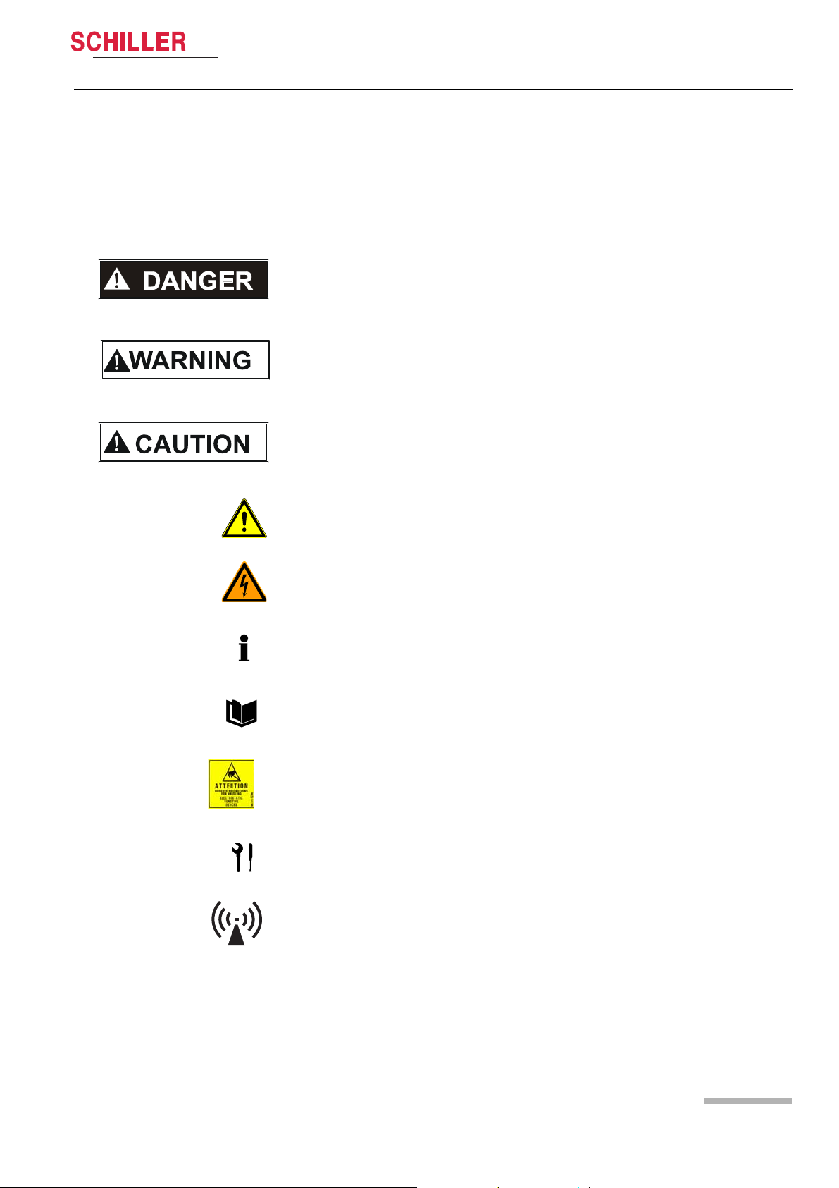
The safety level is classified according ANSI Z535.4. Th e following overview shows
the used safety symbols and pictograms used in this manual.
For a direct danger which could lead to severe personal injury or to death.
For a possibly dangerous situation, which could lead to heavy bodily injury or to death.
For a possibly dangerous situation which could lead to personal injury. This symbol is
also used to indicate possible damage to property.
For general safety notes as listed in this chapter.
Used for electrical dangers, warnings and other notes in regarding operation with electricity.
Note For possibly dangerous situations, which could lead to damages to property or
system failure. Important or helpful user information
Reference to other guidelines
Observe precautions for handling electrostatic sensitive devices.
Used tool for the following procedure.
Interference may occur in the vicinity of equipment marked with following Symbol “non
ionizing radiation” (see chapter 12.4 page 131)
Art. no.: 2.540033 rev.: d
Page 9
Page 12
1 Safety notes
1.7 Safety Symbols and Pictograms
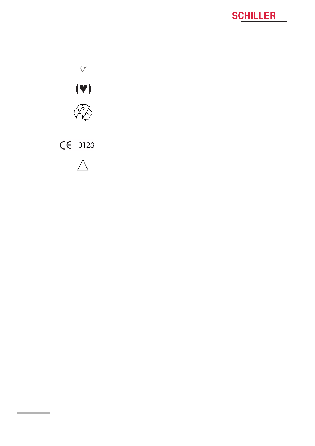
1.7.2 Used symbols on the device
ARGUS LCM/PLUS
Potential equalization
CF symbol. This unit is classified safe for internal and external use. However, It is only
defibrillation protected when used with the original SCHILLER patient cable!
Inappropriate disposal can lead to environmental pollution.
Units/components and Accessoires no longer required can be returned to SCHILLER
AG for disposal. Alternatively, the unit should be d isposed of in a municipally approved recycling centre.
Notified body of the CE certification (TÜV P.S.)
Attention: Consult accompanying documents.
Page 10
Art. no.: 2.540033 rev.: d
Page 13

Introduction 2
ARGUS LCM/PLUS
Service Handbook Version overview / compatibility 2.1
2 Introduction
Following an overview of the different version of the ARGUS LCM/PLUS (Low
Weight and Compact Monitor)
2.1 Version overview / compatibility
2.1.1 ARGUS LCM (basic) from serial number 781.000-781.999
The following table shows the equipment of the ARGUS LCM. This basic device cannot be upgraded.
ARGUS LCM ECG SpO2 NIBP Microprocessor Connector board
Basic device Only with 3 leads/display one lead (II) x x MK19-10 MK19-50
Options: printer, additional battery (can be updated in the field)
2.1.2 ARGUS LCM (basic) from serial number 781.1000-xxxx
The microprocessor board MK19-11 is populated with a monitoring ECG amplifier.
This supports 2 cables. 3p-lead cable (RA, LA, LL and measures 6 derivations) and
5-lead cables. This works only with software 1.24 and higher.
ARGUS LCM
Axxxx1x MK19-11MK19-5
B x x x x 1x x MK19-11 MK19-5
D x x x x 1x x MK19-11 MK19-53
E x x x x x x
a
Monitoring amplifier only with 3p- and 5 lead cable (6 or 7 lead display).· Modus-x possible.
• Options for all versions: printer, additional battery and nurse call or vehicle power supply.
• Version A can be upgraded with etCO
a
ECG
SpO2 NIBP Respiration Temp. etCO
module, printer and additional battery.
2
IBP Microproces-
2
sor board
Connector
board
MK19-11 MK19-54
2.1.3 ARGUS LCM PLUS from serial number 780.001-xxxx
ARGUS LCM PLUS
Version
A x x x x 1x MK19-1 MK19-5
B x x x x 1x x MK19-1 MK19-5
D x x x x 1x x MK19-1 MK19-53
E x x x x x x MK19-1 MK19-54
a
Only with 3- or 5- or 10 lead cable (1- or 7- or 12 lead display).
• Options for all versions: printer, additional battery and nurse call or vehicle power supply.
Art. no.: 2.540033 rev.: d
• Version A can be upgraded with etCO
a
SpO2 NIBP Respiration Temp etCO2IBP Microproces-
ECG
module, printer and additional battery.
2
sor board
Connector
board
Page 11
Page 14

2 Introduction
2.1 Version overview / compatibility
2.1.4 Nurse call option version 1
2.1.5 Nurse call option version 2
ARGUS LCM/PLUS
The version 1 is prepared only for a relays contact NO.
Board number Board type LCM version Index
3.2561 MK19-5 Basic/LCMplus version A and B A
3.2564 MK19-50 Basic A
Following boards indexes are prepared with potential free change over contact relays
NO/NC.
Board number Board type LCM version Index
3.2561 MK19-5 Basic/LCMplus version A and B C
3.2564 MK19-50 Basic B
3.2566 MK19-53 Basic/LCMplus version D A
3.2567 MK19-54 Basic/LCMplus version E A
Nurse call cable version 2 p/n 3.920908.
With the same boards index changes Masimo MS-7 to MS-3 board.
2.1.6 SpO2 sensors Masimo and Nellcor MP-100
The LCM can be equipped with Masimo or Nellcor SpO2 sensors. The type of used
sensor is applied on the front of the LCM housing. If LCM will b e upgrade d, the typ e
of used sensor must be labelled on the front of the LCM housing.
Nellcor module
Following board indexes are prepared to equip with Nellcor module
Board number Board type LCM version Index
3.2561 MK19-5 Basic/LCMplus version A and B C
3.2564 MK19-50 Basic B
3.2566 MK19-53 Basic/LCMplus version D B
3.2567 MK19-54 Basic/LCMplus version E B
2.1.7 LCD display replacing version 1 to 2
Page 12
The LCD version 1 (Samsung 16 pin) have been replaced by LCD version 2 (AU Optronics 20 pin). The table below shows the board compatibility for LCD version 2.
Board number Board type LCM version Index
3.2574 MK19-11 Basic > xxx.1000
Board prepared but 20 pin connector
not soldered in.
3.2574 MK19-11 Basic > xxx.2000
Board ready with 20 pin connector
AA
BB
Art. no.: 2.540033 rev.: d
Page 15

ARGUS LCM/PLUS
Introduction 2
Service Handbook Version overview / compatibility 2.1
Board number Board type LCM version Index
3.2563 MK19-10 Only 14 pin connector. Only LCD version 1 can be used
3.2560 MK-19-1 Only 14 pin connector. Only LCD version 1 can be used
3.2560 MK-19-1 20 pin connector. Only LCD version 2
can be used. Requires new housing.
Board 19-11 with index FA has the 20 pin connector at the backside.
Board 19-10 and 19-1 index F has only 14 pin LCD connection, so only LCD version
1 can be used.
To replace a defective LCD version 1 with the LCD version 2 a new fro nt housing is
needed. See following table where a front is needed.
E
E
FC
Housing V2 = Sticker for SpO
module + Schiller = LCD version 2
2
LCM Type Serial number LCD Type Front required
LCM Basic 781.0000 - 781.01716 Samsung Yes
LCM Basic 781.02000-xxxxx AU Optronics No
LCM plus 780.0000 - 780.03183 Samsung Yes
LCM plus 780.03184-780.xxxxx AU Optronics No
2.1.8 NIBP pump versions
ARGUS LCM plus / basic V1
• 1300 ccm
• 4.330040
780 / 781.xxx - 2999 x x
780 / 781.xxx - 2999 x x optional preferred
780 / 781.3000- xxxx x x
Board/ Index
MK-1/EV x
MK-10/AF x
MK-11/BE x
• 1300 ccm
• 3.920921
V2
V3
• 2300 ccm
• 4.330044
201R
Current limit 1 A
301R
Current limit 1.3 A
Art. no.: 2.540033 rev.: d
Page 13
Page 16

2 Introduction
Access to the menu IBP and NIBP alarm
on/off and IBP calibration.
IBP connection instead of CO
2
This is the LCM plus
version E.
This is the LCM plus
version D.
IBP connection instead of Temperature
2.2 Functional overview
ARGUS LCM/PLUS
2.2 Functional overview
2.2.1 Buttons of the ARGUS LCM PLUS
Page 14
Fig. 2.1 ARGUS LCM front view
Art. no.: 2.540033 rev.: d
Page 17
ARGUS LCM/PLUS
Introduction 2
Service Handbook Functional overview 2.2
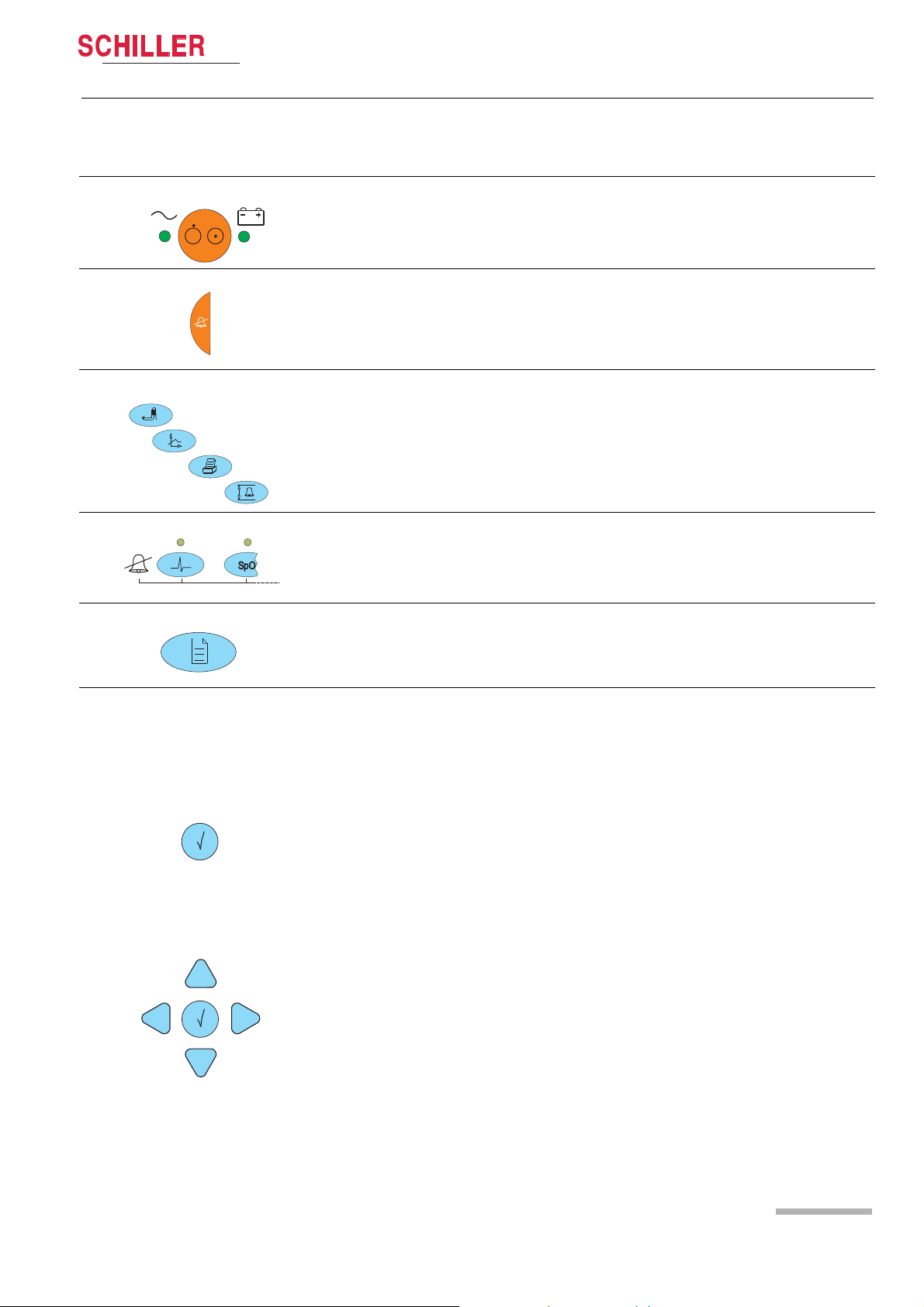
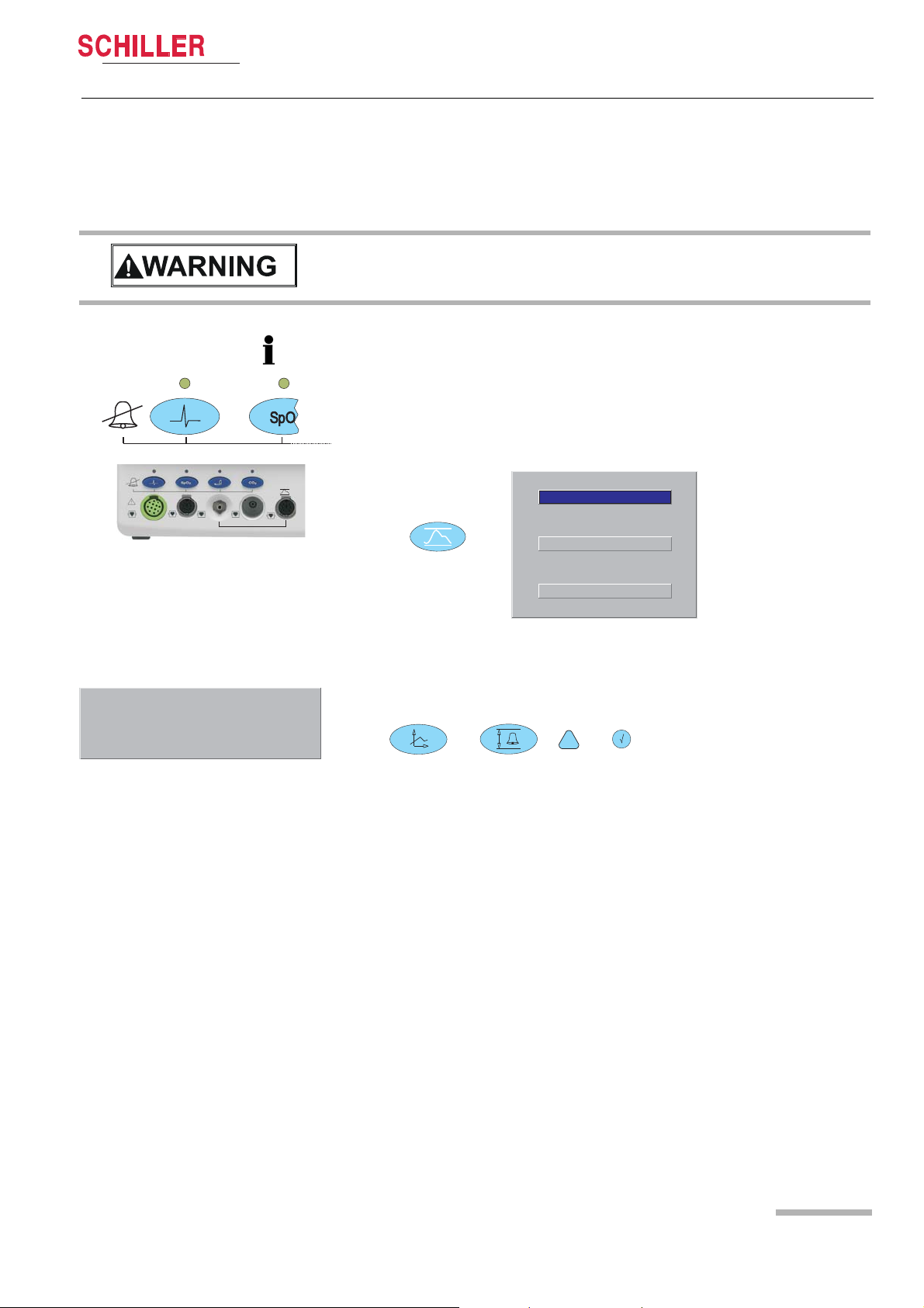
2.2.2 Description of buttons
ON/OFF
The LED indicates if the LCM is running from mains power or battery.
Button for suppression/acknowledgement of audible alarms
The alarm can be suppressed or acknowledged in two ways. This is defined in set-
tings About+/Alarm setup menu.
See detailed description in paragraph 3.6.2
Direct buttons for:
(1) NIBP start/stop or, if pressed for 2 s, switch between auto and manual
(2) Trend and alarm displays
(3) Printout of the current display
(4) Alarm limit settings
Art. no.: 2.540033 rev.: d
Enter
Navigation
Alarm off
These buttons disable alarms of the individual parameters. Acknowledgement is
displayed on the top left e.g. ECG Alarm OFF. The LED above the corresponding
button is lit (for details refer to section 3.6.3).
Menu access
Opens the main menu. Navigate through the menus with the right/left buttons.
Press the menu button to again leave the menu.
The navigation and enter buttons have different functions dependent on operating
mode:
Normal single lead display:
Pressing the enter button shows the first 3 leads instead of the single lead display.
By pressing the up/down buttons, the next lead, or lead group is displayed.
Press the left button to adjust the loudness of the audible alarm and the QRS sig-
nal.
Programming mode:
1. Activating the programming mode with the menu button.
2. Selecti ng the menu with the left/right buttons.
3. Selecti ng a value with the up/down buttons.
4. Press the enter button.
5. Change a value using the up/down buttons.
6. Retrieve a value by pressing enter.
Trend display mode:
Activate the trend display mode with the trend display button.
Use the
left/right buttons to move forward/backward in the trend display.
Use the trend button to toggle between the trend display, alarm display and normal
monitor display.
Page 15
Page 18
2 Introduction
HR
/ min
60
98
60
SpO
2
PP
/ min
%
10
RRi
/ min
R
P
P
I
II
III
11 :04 28-10-04
127/77
(100
)
36.8
T
1
°C
Alarm HR Low ECG lead off
I
I
II
III
I,II, …
aVR, III,...
>0:12
1
2
3
56
78
PM ON
SYS/DIA
(MAP)
4
PM detection
RRi Alarm
switch off
NIBP
mmHg
<0:12A
9
2.2 Functional overview
ARGUS LCM/PLUS
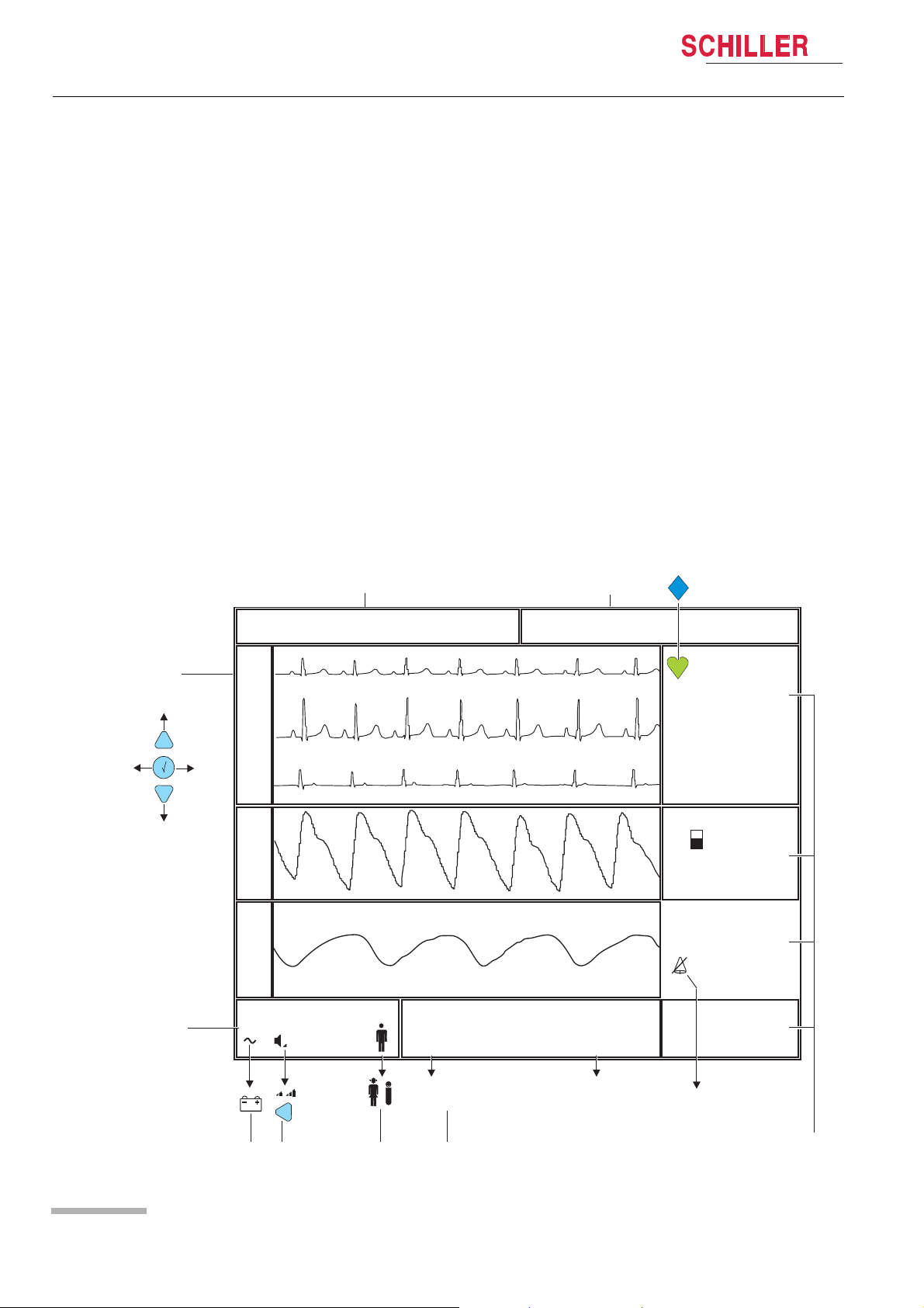
2.2.3 Description of display
Alarms
(1) Status field for physiological alarms
(2) Status field for technical alarms
Curve field
(3) 1 or 3 channel lead display. With enter display 1 or 3 leads, with
up/down select the following/previous lead/lead group.
System status field
(4) System status field
(5) Symbol for battery operation.
(6) Loudness (3-step) for alarm- and QRS-sound. Adjust with left button.
(7) Symbol of the selected patient type.
Blood pressure
(8) < 0:12 A = remaining time (h /min) to the next a utomatic bl ood pressure meas-
urement.
> 0:12 = Time since the last manual blood pressure measurement
Remark: During blood pressure measuring the current system pressure in
mmHg is displayed.
Measurement field
(9) Various displayed values e.g. HR, Sp02, IBP, CO2, RRi, temperature.
Art. no.: 2.540033 rev.: d
Page 16
Page 19

ARGUS LCM/PLUS
Graphic scale : 10 mm/mV
ECG filter : Diagnostic
QRS Beeb source : Off
Pacemaker : Off
RRi alarm : Off
RRi high alarm : Immediately
Cable type : 3-lead
Mains filter : Off Hz
Alarm / Param / Trend / Device / Software
ECG / NIBP / CO2 / System / About
Introduction 2
Service Handbook Functional overview 2.2
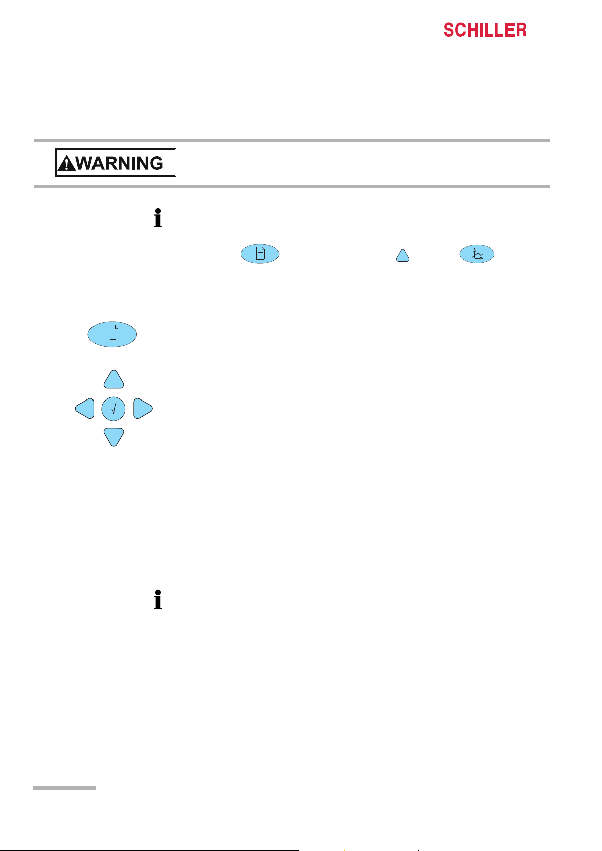
2.2.4 Navigation and changing values in the menu
Fig. 2.2 Picture menu
The upper menu display is normally hidden. The exte nded menu di sp lay can b e di splayed with the following combination of buttons.
Press , select menu About press, and then .
Top change values proceed as follows:
Select with the desired parameter (white box) and press to get ac-
cess and change or selecting value with and confirm with .
The changed value will be not permanently stored. After power off/on the default value will be set. To store changed value as default permanently refer to chapter 3.3.2
Art. no.: 2.540033 rev.: d
Page 17
Page 20
3Operation
Potential equalisation Cable
p/n 2.310056
4.260419
4.260400
3.1 Start-up
ARGUS LCM/PLUS
3 Operation
3.1 Start-up
V Danger of electrical shock. Do not operate the unit if the earth connection is sus-
pect or if the mains lead is damaged or suspected of being
damaged.
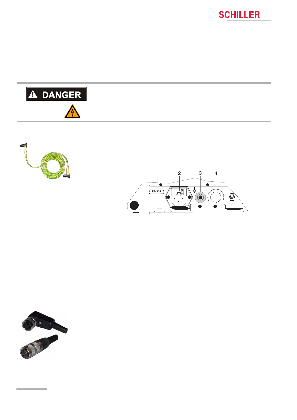
3.1.1 Connecting and power on
(1) RS-232
(2) Mains connection (115 or 230 VAC)
(3) Potential equalisation connection (Cable p/n 2.310056)
(4) Nurse call or DC in 11 - 30 VDC (option)
Fig. 3.2 Boardnet plugs
Fig. 3.1 ARGUS LCM back panel
1. Voltage setting (2) 115 or 230 V. Refer to chapter 4.2 for the mains voltage. Connect the power cable at the rear of the unit.
2. Connect the potential equalisation cable (3) and all other necessary cables at the
rear of the LCM.
3. Press the on/off button.
4. Check that all LEDs flash shortly and there is a beep on sta r t-up.
5. Check the settings according to chapters 3.3 and 10.1.
3.1.2 Boardnet supply
Only with board net supply option installed. (see picture (4) above.
1. See internal cable page 102.
2. Use one of the board net plugs
3. Use a stranded wire with 2.5 mm
er requirements.
Boardnet Supply
11 ...30 VDC, I max. 2.5 A
Remarks: The boardnet connection is not certified to use in ambulance or air rescue.
2
or bigger depending in the cable length and oth-
Art. no.: 2.540033 rev.: d
Page 18
Page 21

ARGUS LCM/PLUS
1
Operation 3
Service Handbook Switching off and disconnecting from mains 3.2
3.1.3 Battery operation
Important
The Battery operation is indicated by the LED below the battery symbol.
When the battery charge is low, the alarm message Battery low appears and
– the LED (1) blinks
– the Battery symbol in the bottom left display field blinks
for Battery recharging refer to chapter 4.1
3.2 Switching off and disconnecting from mains
1. Press the on/off button. A dialogue window appears.
2. Select with the left button YES and confirm the selection with the enter button.
3. Remove the mains cable from the mains supply socket (2) (see Fig. 3.1) to isolate
the device from the mains.
Important
If no dialogue window appears it is possible to switch off the device by keeping the
On/Off button pressed for 10 seconds.
3.2.1 Interruption of the mains supply
If the mains supply is interrupted, the device automatically switches over to battery
operation. The user settings are maintained. These settings can be saved in the menu
About+/Software.
Art. no.: 2.540033 rev.: d
Page 19
Page 22
3Operation
3.3 Initial settings
ARGUS LCM/PLUS
3.3 Initial settings
This chapter details the most important and typical programming sequences.
V Only authorised personnel, trained in the operation of this device, are permitted
to do the setups in the following menu.
The extended menu display About+ can be displayed with the following combination
of buttons.
Press , select menu About press, and then .
3.3.1 Selecting the language
1. Open the menu About+ and select menu Device.
2. Confirm with the enter button.
3. Press the down button and select the language.
4. Confirm with the enter button.
5. Press right/left to move to the next menu and continue with more setups.
6. Save the user settings. Open the menu Software, select Save as Default and
confirm with the enter button.
7. Return by pressing the menu button to the normal display mode.
For system settings see detailed list in the chapters 10.1.1and 10.1.2.
3.3.2 Save and restore default settings
Changed values can be stored permanently and again restored. See chapter 10.1.2.
1. Select the menu About+/Software.
2. Select Save as Default or restore Defaults and confirm with the Enter button. It
will now save or restore the default settings.
3.3.3 Load factory defaults
The SCHILLER factory defaults are listed in chapter 10.2. When you load these defaults, they will over write the user settings and language changes to german default.
If selecting factory defaults the language changes to english default settings.
1. Open the menu About and select menu Software.
2. Select function factory defaults and confirm with the enter button. The factory
defaults will be loaded.
3. Press the menu button to exit the programming mode.
Art. no.: 2.540033 rev.: d
Page 20
Page 23

ARGUS LCM/PLUS
Operation 3
Service Handbook Initial settings 3.3
3.3.4 Setting alarm limits
All alarm limits are reset to the default or user specific system settings after switching
the unit off/on, if they have not been stored as default. (see menu About+/Software)
There are no alarm limits for temperature.
1. Press alarm limit button.
2. Press up/down or left/right buttons to select an alarm parameter and confirm
with enter. The entry field appears blue.
3. Press up/down to change the value and confirm with the enter button.
4. Press the up/down or left/right buttons to select other parameters or press the
alarm limit button to exit the menu.
The following table gives the default alarm limits settings for adul ts. A changed value
can be stored as default in the menu About+/Software.
The factory defaults are listed in the sections 10.1 and 10.2.
Alarm Low High Unit
a
Prio.
b
HR 50 140 /min High Off
ASYS 2 s High Off
c
RRi
C
APNi
SpO
2
8 35 min Low Off
20 s High Off
90 101 % Low Off
PP 50 140 min High Off
SYS 100 140 mmHg Low Off
DIA 40 95 mmHg Low Off
MAP 70 140 mmHg Low Off
Ps 95 50 mmHg low Off
Pm 50 100 mmHg low Off
Ps 40 100 mmHg low Off
eCO
2
35.0 45.0 mmHg Low Off
CO2 i 0.0 1.5 mmHg Low Off
RRc 8 25 /min low Off
APNc 25 s low Off
a. "High" priority = audible signal with 2 x 5 impulses.
"Low" priority = audible signal with 1 x 2 impulses and 20 s pauses between the
impulse sequences.
b. Print "On" = Default printout containing a warning message when the min./max.
value is exceeded.
c. If the RRi alarm option is Off in the ECG settings panel, the "Low" and "High" val-
ues for RRi and APNi will be "Off".
Print
Art. no.: 2.540033 rev.: d
Page 21
Page 24

3Operation
3.3 Initial settings
ARGUS LCM/PLUS
3.3.5 Setting loudness of audible alarm and QRS sound
1. Select normal mo nitor mode. Press menu if in pr ogramming mode or trend if in
trend display.
2. Press the left button to adjust the loudne ss. The pictogram in the sta tus display
on the bottom left shows the current setting.
Page 22
Art. no.: 2.540033 rev.: d
Page 25
ARGUS LCM/PLUS
Operation 3
Service Handbook Trend or alarm display 3.4
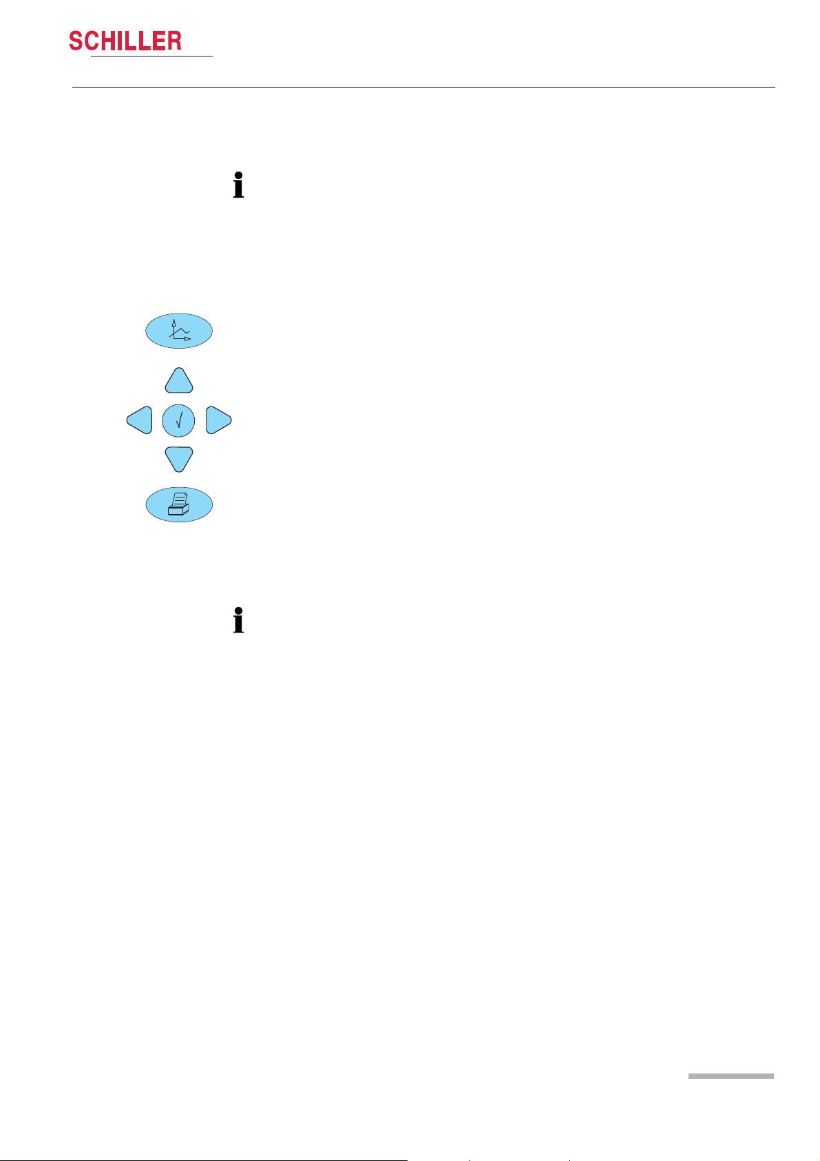
3.4 Trend or alarm display
The trend values are stored for all parameters every minute and additional ly on every manual NIBP measurement over the last 24 hours. The trends can be displayed
in graphical or tabular.
The display interval for the table can be selected in the menu About+/Trend. The
displayed trend table or not acknowledged alarms can be printed out by pressing
the print button. The displayed graph cannot be printed.
Table display
1. Press the trend button. The trend will be displayed in a table in 1, 5,15, 30, 60,
120 or 240 minute intervals. Change the displayed interval using the up/down
button. Move the display forward/backward on the time axis using the left/right
button.
Graph display (cannot be printed)
2. To display the graph, press the trend button once again. The graph's time frame
corresponds to 3 hours. Display the next 3 h by pressing the up/down button.
Move the cursor on the top right corner using the right/left button to display the
exact measured values for the selected position on the right. The cursor can be
positioned on the NIBP value by pressing ENTER.
Display of not acknowledged alarms
3. To display the last 12 no t acknowledged alarms, press the trend button a third
time.
3.5 Display of additional leads
The LCM basic serial number 0-999 can only measure lead II.
1. Select the normal monitor mo de. Press menu if in programming mode or trend
if in trend display.
2. Press the enter button to switch between the normal display mode containing
one lead and the 3-lead display.
3. By pressing the up/down buttons, the next leads are displayed.
Art. no.: 2.540033 rev.: d
Page 23
Page 26

3Operation
3.6 Procedure in case of an alarm
3.6 Procedure in case of an alarm
3.6.1 Display of alarms
3.6.2 Suppressing/acknowledging an audible alarm
ARGUS LCM/PLUS
During initial switching on
The alarms are suppressed for a defined time (programma ble in the menu About+/
Alarm. Alarm suppr. time standard is 3 minutes)
The message Alarm suppressed 3:00 appears.
During monitoring
There are two alarms:
• Technical alarm, displayed in the alarm status field on the top right.
In case of a technical alarm, an audible alarm sounds and the measurement field
for the respective value flashes.
• Physiological alarms, displayed in the alarm status field on the top left.
In the case of a physiological alarm, an acoustic alarm sounds and the mea surement field for the respective value flashes.
There are two ways to proceed in the case of an alarm. The procedure dep ends on
the set alarm stop mode (On/Off) and the alarm suppression time in the menu
About+/Alarm:
(1) Alarm stop off (suppression)
This function suppresses an audible alarm for a defined period of time (2..10 min.).
However, the flashing measurement field (red measured value and coloured field) will
remain. The audible alarm is reactivated after the defined period of time has elapsed.
(2) Alarm stop on (acknowledging)
This function will suppress an audible alarm as long as the defined alarm limits are
exceeded. However, the flashing measurement field (red measured value and coloured field) remains.
3.6.3 Preventive alarm suppression
The preventive alarm suppression is used to deactivate in advance all alarms that
may be caused by disconnecting patient cables, loose electrodes an d relocation of
the patient.
« Press the alarm button and confirm with the enter button before an alarm is dis-
played.
Message Alarm suppressed 3:00 is displayed. The time can be programmed in the
menu About+/Alarm/Alarm suppr. time.
As soon as the time has expired, the acoustic and the visual alarms are again reactivated.
Page 24
Removing of the patient cables
If a cable is removed the message Cable off or no Sensor is displayed.
« Press the button alarm suppressing.
The alarm is deleted and the measured value field is no longer indicated.
Art. no.: 2.540033 rev.: d
Page 27
ARGUS LCM/PLUS
IBP Alarm On/Off
Connect zero mmHg
Start IBP calibration
End / Escape
Enter Password
Press [Enter] to cancel
I,II, III
Operation 3
Service Handbook Procedure in case of an alarm 3.6
3.6.4 Switching off an alarm
Each alarm off function is password protected. Read carefully the followi ng warning
and information:
V When the acoustic alarm is switched off, the patient acoustic physiological
alarms are silenced and suppressed indefinitely. Use this function only if disconnecting a sensor from the patient for a long period of time.
• When the alarm off button is pressed, the audible alarm for the respective parameter is suppressed. This is indicated by the LED above the button and a message
on the monitor, e.g. Alarm ECG OFF. If an alarm occurs as long as the alarm off
button is pressed, a visual alarm is displayed in the respective measurement field.
• With the LCM plus version E the access to the IBP alarm off function will be executed by the NIBP alarm button. A menu with blood pressure a larm off (common
for NIBP and IBP) and IBP calibration function appears.
Entering alarm OFF password
1. Press the desired alarm off button. The password dialog appears.
2. Press following button to enter the password:
, , ,
1. The password protection can be disabled in the special menu see chapter 4.1.2
page 29
Art. no.: 2.540033 rev.: d
Page 25
Page 28

3Operation
3.6 Procedure in case of an alarm
3.6.5 Overview of physiological alarms
ARGUS LCM/PLUS
Alarm abbreviation Description
Asys limit Asystole time limit exceeded
SpO2 Low/High
PP Low/High
RRi Low/High Respiration rate impedance (from ECG electrode)
Apnea limit Apnea time limit exceeded
CO2i low/high Inspiratory CO
RRc low/high Capnographic respiration rate
eCO2 low/high End-tidal expiratory CO
SYS low/high Systolic pressure
DIA low/high Diastolic pressure
MAD low/high Mean atrial pressure
HR low/high Heart rate
Ps low/high Invasive systolic blood pressure
Pm low/high Invasive mean blood pressure
Pd low/high Invasive diastolic blood pressure
Temp low/high
Oxygen saturation of the blood
Peripheral pulse of SpO
2
2
2
When the temperature is outside the measuring range,
this is indicated by “<<“(below 15 °C) or “>>” (above 45
°C). This limit is fixed.
Page 26
Art. no.: 2.540033 rev.: d
Page 29
ARGUS LCM/PLUS
Operation 3
Service Handbook General Cleaning instructions 3.7
3.7 General Cleaning instructions
3.7.1 Cuff cleaning
V Do not use Chlorine
V Do not autoclave
V Follow the manufacturer’s instruction. (Disinfectants and Cuff)
• If using machine washing, be sure that the hook and loop fastener are engaged
• The fastener can melt at temperature above 325° F / 162° C, when being ironed.
• Use 70% isopropyl alcohol or mild detergent for cleaning.
1. Remove the rubber inflation bag from the cuff.
2. Disinfect cuff and inflation bag if necessary or wash the cuff in warm, soapy water.
3. Rinse thoroughly to remove any residual disinfectants because of skin irritation.
3.7.2 SpO2 Sensor
V Do not use undiluted bleach (5...5.25 % sodium hypochlorite)
V Do soak or immerse the cable or the sensor in any liquid solution
V Do not autoclave
V Follow the manufacturer’s instruction. (Disinfectants and Sensor)
• Use 70% isopropyl alcohol or mild detergent for cleaning.
1. Disconnect sensor from the device.
2. Disinfect sensor an d cable by wiping it with a 70% isopropyl alcohol pad.
3. Allow the sensor to dry prior to placement on a patient.
3.7.3 ECG cable
V Do soak or immerse the cable in any liquid solution
V Do not autoclave
V Follow the manufacturer’s instruction. (Disinfectants and Cable)
• Use 70% isopropyl alcohol or mild detergent for cleaning.
1. Disconnect cable from the device.
2. Disinfect cabl e and clip by wiping it with a 70% isopropyl alcohol pad.
Art. no.: 2.540033 rev.: d
3. Allow the cable to dry prior to placement on a patient.
Page 27
Page 30

4 Setup and Programming
4.1 Settings menu
ARGUS LCM/PLUS
4 Setup and Programming
4.1 Settings menu
4.1.1 Main menu
Bold marked values are factory settings.
Main menu Parameter Values
ECG Display sensitivity 5/10/20/40 mm/mV
a
ECG - Filter
QRS beep source Off/ ECG/ SpO
Pacemaker Off /On (If pacemaker on, it is no RRi measuring possible)
RRi Alarm On /Off
Cable type Display of the connected cable type (3p-,/3-/5-/10-lead)
Mains filter Off/ 50 or 60 Hz
NIBP Initial pressure Adult 180, pediatric 150, neonatal 120 mmHg (0..300)
Autom. measuring Off/ On
Interval time 2/3/5/10/15/ 30/60 min
Deflation speed 5 (3..9) mmHg
SpO2 suppression Off/ On
IBP Scale 0..300/200/100/50/30/Auto
Start IBP Calibration Function
CO
2
System Patient Adult/Pediatric/Neonatal
About Device info see section 7.7.2
a.Diagnostic (Hardware, filtering low):High/low-pass: hp = 0.05 Hz, lp = 150 Hz for LCMplus and LCMbasic SN < 1000
Monitoring 1 (Hardware, filtering low):High/low-pass: hp = 0.5 Hz, lp = 40 Hz for LCMbasic SN > 1000
Monitoring 2 (Hard & Software, filtering medium):Hardware see above, SW
Artefact (Hard- and Software, filtering high):Hardware see above, SW
Flow Rate 200/120/90 ml/min (see details page 31)
O2-Compensation Off/ On (Off = O2 ≤ 60% / On = O2 > 60%)
N
O Compensation Off/ On (Off = 0% N2 O /On = ≥ 12%)
2
Desflurane compensation Off/ On (On = Desflurane ≥ 12%)
Steam compensation Off/ On
BTPS compensation Off/ On
Zero point cal. date ddmmjj
Two point cal. date ddmmjj
Start zero Point Calibration Function
Start two-Point Calibration Function
Date ddmmjj
Time hhmm
Diagnostic/ Monitoring 1 / Monitoring 2 / Artefact
2
= 0.6 Hz, SWlp = 35 Hz
hp
= 2.4 Hz, SWlp = 20 Hz
hp
Art. no.: 2.540033 rev.: d
Page 28
Page 31

ARGUS LCM/PLUS
Service Handbook Settings menu 4.1
4.1.2 Special menu “About+”
V Only authorised personnel which is trained in the operation of this device is al-
lowed to do the setups of the following menu.
The extended menu display About+ can be displayed with the following combination
of buttons.
Press , select menu About, press and then
Main menu extended Parameter Value
About+
Alarm Alarm stop mode On/Off
Alarm suppr. time 2 min (2 ... 10)
Alarm sound DIN EN 475/Standard
Nurse call Immediately/in 5 sec.
Alarm restriction (see page 25) On/Off
Param
Trend
Device Language
Software Save as default
Art. no.: 2.540033 rev.: d
Lead II
Lead speed 12.5/25/50 mm/s
Respiration source
a
ECG/CO
2
Respiration speed 6.25/12.5 mm/s
SpO2 Pulse
SpO
sensitivity
2
4/8 or 16 s
Low /High
NIBP adult Initial 180
NIBP pediatric Initial. 150
NIBP neonatal Initial 120
NIBP MAP On
Temperature unit °C /°F
CO
2
mmHg/kPA/Vol%
View time 5, 15, 30, 60, 120, 240 min
English/Deutsch/
iano/Español/Portuges/Norge
With this function, changed values can be perma-
nently saved. (See section 3.3.2.)
Restore defaults
Factory Default
With this function, the saved default values can be re-
stored. (See section 3.3.2.)
With this function, the factory default values can be
restored.see section 3.3.3
Service see section 8.2
Program update see section 8.2
Setup and Programming 4
b
Français/Svenska/American/Ital-
a. Wh en the set respiration source is ECG and the pacemaker is on, respiration measure ment via the ECG is not possible. The resp i-
ration wave field is not displayed in this case.
b. The Russian language requires a separate software.
Page 29
Page 32

4 Setup and Programming
4.2 Factory settings
ARGUS LCM/PLUS
4.2 Factory settings
These values can be loaded from the menu About+/Software. See section 10.1.2.
Parameter Abbrev. Unit Type Limit Step Alarm
Adult Child Neonat
Prio.
Heart rate HR min High 80...220 5 Low 140 180 200
min Low 15...100 5 50 70 90
Asystole s 2...20 1 High 2 2 2
Respiration RR min High 25...120 5 Low 35 35 60
min Low 1...20 5 6 12 20
Apnea s 15...45 1 Low 20 15 10
NIBP SYS mmHg High 80...300 5 Low 180 180 80
mmHg Low 10...150 5 100 100 50
DIA mmHg High 30...120 5 Low 95 95 45
mmHg Low 0...80 5 40 40 30
MEAN mmHg High 0...200 5 Low 140 140 45
mmHg Low 0...100 5 70 70 30
Pulse min High 80...220 5 Low 140 180 200
min Low 15...100 5 50 70 90
Pulsoximetry SpO
PP min High 80...220 5 Low 140 180 200
Capnography eCO
CO
eCO
CO
eCO
CO
IBP Ps mmHg High 0...300 1 Low 180 180 180
Pm mmHg High 0...200 1 Low 100 100 100
Pd mmHg High 0...120 1 Low 100 100 100
T
1
T
1
% High 80...101 1 High 101 101 98
2
% Low 70...99 1 90 89 88
min Low 15...100 5 50 70 90
Vol% High 4.5...10 0.1 Low 6.0 6.0 6.0
2
Vol% Low 0...6.0 0.1 4.5 4.5 4.5
i Vol% High 0.1...1.5 0.1 Low 0.2 0.2 0.2
2
Vol% Low 0...1 0.1 0 0 0
kPa High 4.5...10 0.1 Low 6.0 6.0 6.0
2
kPa Low 0..6.0 0.1 4.5 4.5 4.5
i kPa High 0.1...1.5 0.1 Low 0.2 0.2 0.2
2
kPa Low 0...1 0.1 0 0 0
mmHg High 35.. 76.0 0.5 Low 45.0 45.0 45.0
2
mmHg Low 0. .45.0 0.5 35.0 35.0 35.0
i mmHg High 1.. 10.0 0.5 Low 1.5 1.5 1.5
2
mmHg Low 0.. 8.0 0.5 0 0 0
mmHg Low -20...150 1 95 95 95
mmHg Low -20...150 1 50 40 40
mmHg Low -20...80 1 40 40 40
°C or °F No ala rm N o s etti ngs - - - - -
Art. no.: 2.540033 rev.: d
Page 30
Page 33

ARGUS LCM/PLUS
Service Handbook CO
4.3 C O2 settings
4.3.1 Description of CO2 parameters
Parameter Setup Description
Flow rate
O2-Compensation
N
O-Compensation
2
Desflurane
Comp.
Steam
Compensation
BTPS compensation
200/120/90 ml/min
Off/On
Off/On
Off/On
On/Off
To ensure that children and neonates have sufficient air to brea the, it is vital
that the "System > Patient" ("Adult", "Pediatric", "Neonatal") and the CO
tings be checked. The flow rate for CO
children and 90 ml/min for neonates.
Correction factor for O2 = 1.03
Additional oxygen O
in the CO2 gas mixture reduces the IR absorption in
2
the sensor. This leads to too low results when the CO
rection is activated when the O
Correction factor for N2O (laughing gas) = factor 0.952
Additional N
O increases the IR absorption. However, N2O does not influ-
2
ence the IR absorption directly but reduces the CO
energy. The CO
molecule can therefore absorb more energy (IR radiation).
2
Correction factor for desflurane = 0.952, as for N2O.
The compensation is activated when the desfluran e concentration is greater
than 12%. However, it has the same effect as N
Steam affects the IR absorption by CO
ed mathematically.
The compensation is activated during normal side-stream measurement.
During control loop measurement, e.g. CO
tion is deactivated.
Body temperature, ambient pressure, saturated wi th stea m.
Setup and Programming 4
2
measurement must be 120 ml/min for
2
is measured. The cor-
2
values are greater than 60%.
2
molecule's absorption
2
O compensation.
2
molecules. Its influence is calculat-
2
in the incubator, the compensa-
2
settings 4.3
set-
2
On/Off
This factor compensates differences regarding humidity saturation in inspired and expired air. This compensation is used for side-stream measurement, as the device assumes 100% humidity and a temperature of 37 °C for
expired air.
4.3.2 Compensation settings
O2<-Compensation
Off Off Off
On Off Off
Off On Off
Off Off On Desflurane greater than 12%
On On Off
Art. no.: 2.540033 rev.: d
N2<O-
Compen-
sation
Desflu-
rane
Comp.
Condition
O
less than 60%, no N2 O or
2
25% N
O2 grater than 60 %, no N2O
N
O
12%
O and 75% O
2
O greater than 12%
2
greater than 60%, N2O greater than
2
2.
Page 31
Page 34

4 Setup and Programming
1
CO
2
t
4.3 CO
Capnography
settings
2
4.3.3 Combination of N2O and O2 compensation
As the influence on N2O is greater than on O2, the influences can cancel each other
out in a gas mixture of 25% N
O and 75% O2. In that case, both compensations can
2
be deactivated. The overall correction when both compensations are acti ve is 0.99.
4.3.4 Environmental pressure compensation
The environmental pressure is automatically compensated when the unit is
switched on or the watertrap is connected.
4.3.5 Measuring principle Pryon LC110 CO2 Module
ARGUS LCM/PLUS
Fig. 4.1 Capnography
Measurement Calculation
Capnography is the non-invasive measurement and graphic displa y of airway CO
concentration as a function of time. The resulting waveform is called capnogram. The
evaluation of the capnogram is useful in the assessment of the carbon dioxide exchange in the lungs, the integrity of the patient's airways as well as the cardiopulmonary and ventilator functions.
(1) Monitoring of CO
(ETCO2) monitoring.
CO
2
concentration at the end of expiration is referred as end-tidal
2
2
The LC101 provides the following
parameters
Page 32
Fig. 4.2 Block diagram CO2 measuring
•ETCO2 (eCO2)
• Inspiratory CO2 (CO2i)
• Respiratory rate (RRC)
These three measurements are collectively referred to as breath data.
Art. no.: 2.540033 rev.: d
Page 35

ARGUS LCM/PLUS
Setup and Programming 4
Service Handbook CO
settings 4.3
2
Measuring Principle CO
2
The CO2 measurement is based on the infra-red (IR) absorption characteristics of
molecules. The CO2 sensor uses non-dispersive IR spectroscopy to measure
CO
2
the number of CO2 molecules present in the sample gas. CO
sorption band which relates to a CO2 molecule's composition and mass. The CO
gas has a unique ab-
2
2
gas
concentration is measured by detecting the absorption in this band. Due to the nature
of the measurement technique employed, user calibration is necessary with this system.
The basic components of the CO2 sensor (C-Cap bench) include
• IR source
• Dual element IR detector
• Optical filter
• Non-volatile memory
The IR sour ce emits energy that is directed towards a dual element thermopile IR de-
tector. The dual element design uses two opposing thermopiles connected in series.
A change in the ambient temperature is compensated by the two elements so the output won't be distorted. Only one element is exposed to energy from the IR source, resulting in a voltage change due to only that energy. The detector generates a voltage
based on the amount of energy it receives. The IR path between the IR source and
the detector contains an optical filter, which only allows a specific IR wavelength to
pass and the gas sample within the sensor chamber.
A temperature sensor is attached to the detector housing for temperature compensation beyond the thermopile's designed compensation, including temperature changes
in the system sensitivity.
The detector generates a voltage in the mV range and an OP-amp on the circuit board
amplifies the signal.
The non-volatile memory is an EPROM containing calibra tion and manufacturing
data specific to the CO
Measurement Compensation T he IR absorption in th e CO
tors that alter the CO
for some of these factors, while others must be set in the menu. These factors include:
• Steam compensation
• Body Temperature, ambient Pressure and Saturated with water vapour BTPS
• Pressure broadening (automatically always on)
• Gas mixing (automatically always on)
• Oxygen, nitrous oxide and desflurane or O
Art. no.: 2.540033 rev.: d
sensor.
2
wavelength band may be affected by a number of fac-
2
measurement. The LC101 module automatically compensates
2
, N2O, desflurane
2
Page 33
Page 36

4 Setup and Programming
4.3 CO
settings
2
ARGUS LCM/PLUS
Correction for O
Correction for O
, N2O, desflurane
O
2
compensation
2
As the N2 in the sample gas is replaced by O2, the effect is a decrease in IR absorption. This results in a lower than actually measured CO
the additional O
creased be a slight factor to correct for the O
present, the raw measurement from the LC101 module must be in-
2
effect.
2
value (CO2
2
MEASURED
). With
O2 correction is recommended when the O2 concentration is greater th an 60%. At O
levels equal to or less than 60%, no correction should be made.
, N2O To correct for N2O in the sample gas, an assumption is made: if N2O is administered
2
to the patient, then the remaining balance of the administered mixture is O
bined effect of these gases is two-fold. The presence of O
tion, whereas the presence of N
O increases the absorption. Although N2O does not
2
directly absorb the filtered IR energy, it causes the CO
along some of its energy to the N
By passing off some of this energy, the CO
O molecule, which has a similar molecular weight.
2
molecule becomes free to absorb even
2
decreases the IR absorp-
2
molecule to absorb and pass
2
. The com-
2
more energy, which leads to an increased absorption.
Since the increased absorption effect due to N2O presence is greater than the decrease due to the O
75% O
effectively cancels the combined effect.
2
presence, an optimal administered mixture of 25 % N2O and
2
The presence of the oxygen (O2), nitrous oxide (N2O) and desflurane in the gas sample affects the measurement of the CO
IR absorption characteristics of CO
concentration, because these gases have the
2
molecules.
2
2
Correction for O
Steam compensation
(water vapour)
, N2O The effect of desflurane on the CO2 measurement is similar to the effect of N2O. For
2
desflurane concentrations above 12%, the N
O correction may be applied.
2
Water vapour compensation accounts for the effect that water vapour has on the IR
absorption characteristics of CO
measurements are adjusted mathematically to compensate for this effect.
CO
2
molecules. During normal sidestream operation,
2
The host may choose to disable this compensation when performing dry gas measurements in which the gas does not contain water vap our. Dry gas procedures may
include steady state measurements and calibration procedures. Steady state measurements are performed only when background CO2, or CO2 present in the immedi-
ate environment, is measured. An example of a steady state measu rement is measuring the CO
content inside an incubator. Calibration procedures use calibrated gas
2
which is free of water vapour, or dry, as well.
BTPS The clinician's intent is often to determine the CO
where the gas exchange takes place. BTPS compensation corrects for the envi ronmental differences between the measurement site (i.e. the bench) and "deep lung"
.
CO
2
levels within the patient's lungs
2
Art. no.: 2.540033 rev.: d
Page 34
Page 37

Setup and Programming 4
ARGUS LCM/PLUS
Occlusion A total blockage in some region of the inlet tubing, or a total inlet occlusion, is typically
Leakage Test A total inlet occlusion can be useful to check for internal pneumatic leaks. When the
Service Handbook CO
settings 4.3
2
caused by a kinked or occluded sample line, a fully saturated watertrap or an occluded secondary shutoff filter. In the event that this condition occurs, the pneumatic system increases the pump speed to achieve a high clearing vacuum (HCV) for 5 seconds. If the occlusion is cleared by this action, the pump returns to normal operation.
If the occlusion is not cleared after 5 seconds, the module automatically reverts to a
hold, or low clearing vacuum (LCV) state, for up to 15 minutes. During this condition,
the module responds to "CO2 Occlusion" message bar (right on the top). If the occlu-
sion is not removed after 15 minutes of LCV, the module reverts to the stand-by mode
and a new measurement of auto run mode command must be issued to start CO
waveform and breath data packet transmission.
module goes into LCV state, the pump operation remains relatively stable in holding
the vacuum.
However, if there are leaks within the overall system, the pump speed is increased to
maintain LCV. The module may toggle between the normal and inlet occluded states
depending on the magnitude of the leak. A specific connection may also be tested by
blocking specific locations in the pneumatics.
2
Art. no.: 2.540033 rev.: d
Page 35
Page 38

4 Setup and Programming
Lead AHA IEC
ILA - RA
L - A
II LL - RA
F - R
III LL - LA
F - L
aVR = R - 0.5 (L + F) aVL = L - 0.5 (L + F)
aVF = F - 0.5 (L + RA)
4.4 ECG monitoring setup
ARGUS LCM/PLUS
4.4 ECG monitoring setup
Important
The guidelines for patient electrode placement are provided as an overview only.
They are not a substitute for medical expertise.
Following drawing are using IEC colour code. (see also chapter 4.4.9 page 39)
V Danger of destroying the device during defibrillation! The device is only type CF
protected if the original SCHILLER patient cables are used.
4.4.1 Bipolar Electrode placement according Einthoven
4.4.2 Unipolar derivation and augmentation according Goldberger
Art. no.: 2.540033 rev.: d
N electrode is used as CMRR (Common Mode Rejection Ratio). electrode and electrode off can not be detected.
F electrode is the reference electrode for all derivations.
Page 36
Page 39

ARGUS LCM/PLUS
Black (N)
Yellow (L)
Red (R)
Black (N)
Yellow (L)
Red (R
1
2
3
4
5
1
2
3
4
5
Red (R)
Black (N)
Yellow (L)
Respiration measurement
over the delta impedance of
the peritoneum
1
2
3
4
5
1
2
3
4
5
Red (R)
Black (N)
Yellow (L)
see note
Setup and Programming 4
Service Handbook ECG monitoring setup 4.4
4.4.3 3-leads cable for children and neonates (LCM plus)
Electrode is the reference electrode for all derivations. Only derivation II is available
4.4.4 3-lead cable for respiration
4.4.5 3-lead cable for adults
Note
When the signal amplitude is < 0.5 mV, place the yellow electrode according the following picture instead to adjust the resolution to 40 mm/V. Because of that the artefacts can be reduzed.The signal amplitude is influenced by heart axis.
Art. no.: 2.540033 rev.: d
Page 37
Page 40

4 Setup and Programming
Red (R)
Green (F)
Yellow (L)
Yellow (L)
Green (F)
Black (N)
Red (R)
white (C1)
4.4 ECG monitoring setup
ARGUS LCM/PLUS
4.4.6 3 leads cable 3P (LCM basic)
This 3 lead cable 3P is supported only with th e Monitoring ECG amplifier only. This
amplifier is build in the ARGUS LCM with the Serial number 78 1.1000-xxxx, microprocessor board MK 19-11 and software 1.24 or higher. This combination display 6
derivations. 3 lead cable 3P attribute is R/L/F instead of N/R/L.
4.4.7 Three- and five-lead cables for adults and children (LCM basic/ plus
Art. no.: 2.540033 rev.: d
Page 38
Page 41

ARGUS LCM/PLUS
Red (R)
Black (N)
White/red C1
Yellow (L)
White/Green C3
White/Braun C4
White/Black C5
White/Violet C6
Green (F)
White/Yellow C2
Setup and Programming 4
Service Handbook ECG monitoring setup 4.4
4.4.8 10-lead ECG patient cable (LCM plus)
The following illustration indicates the placement locations for the electrodes of a
ten-lead patient cable.
4.4.9 Electrodes identification and colour code IEC/AHA
The electrode placements shown in this handbook are labelled with the colours according to code 1 requirements. The equivalent code 2 colours are given below.
CODE 1 (usually European) IEC 60601-2-51 CODE 2 (usually American) AHA
System Electrode identifier Colour code Electrode identifier Colour code
R Red RA white
Limb L Yellow LA Black
F Green LL Red
CwhiteVBrown
C1 White/red V1 Brown/red
Chest C2 White/yellow V2 Brown/yellow
according C3 White/green V3 Brown/green
to Wilson C4 White/brown V4 Bro wn/b l ue
C5 White/bl ack V5 Brown/orange
C6 White/violet V6 Brown/violet
Neutral N Black RL Green
Art. no.: 2.540033 rev.: d
Page 39
Page 42

4 Setup and Programming
ECG Amplifier
PM Detection
A / D
Cha nger
EKG
1000 Hz
EKG
500 Hz
Ringbuffer
EKG
250 Hz
Notch
50/
60Hz
Myofilter
Base
line
filter
Arte-
fact
ECG Processing
QRS
Detection
PM Marker
Monitoring curve
PM
Fade
Out
No
Y
N Y
N
Y
N
N
Y
Yes
Resp
250 Hz
25 kHz
4.4 ECG monitoring setup
4.4.10 ECG Processing
ARGUS LCM/PLUS
The incoming ECG signals are low-pass filtered and applied to non-inverting operational amplifiers. The signals are further low-pass filtered, ac coupled and amplified before being applied to the multiplexer. The left leg electrode to the patient is
the signal ground reference signal. To assist in cancelling patient common mode
noise and thus reducing incoming signal distortion, the signal from the patient left
leg electrode is phase shifted 180°. This phase shifted signal is then used to cancel
(or reduce) patient common mode noise via the right leg driver.
Page 40
Art. no.: 2.540033 rev.: d
Page 43

Setup and Programming 4
1
2
3
4
5
1
2
3
4
5
Red (R)
Black (N)
Yellow (L)
G
≈
respiration curve
black
electrode
green
electrode
body
25 kHz
5 μA
max.
min.
average value
upper trigger
Threshold
lower trigger
Threshold
R
average
R1 R2 R3 R4 R5 R6 R7 R8+++++++
8
-------------------------------------------------------------------------------------------------------------=
R
60
R
average
--------------------------- -=
R1 R2
Window 1
R4.
Window 2
ARGUS LCM/PLUS
Service Handbook ECG monitoring setup 4.4
4.4.11 Respiration measuring (RRi)
Respiration Respiration is measured between the left leg- and the right leg patient electrodes
which are placed on the abdomen. The physical action of the patient breathing
causes impedance change and this is used to detect and calculate respiration ra te .
The resistance across the electrodes is approximately 1 kohm + 250 ohm and the
impedance change during respiration is between 0.1 and 3 ohm.
The input signals are modulated with 25 kHz, 5μA, which results in an amplitude
modulated signal. This signal is then high pass filtered, demodulated and wave
shaped and sent to the processor via the multiplexer.
Respiration measuring not possible when using HF-cable
.
Respiration Detection
As with the ECG signal, it is necessary to first determine where a respiration has taken
place (triggering). The respiration triggering in the ARGUS LCM is based on the following principle.
Art. no.: 2.540033 rev.: d
Picture: Determination of the Trigger Thresholds
Using a continuous time window of 32 seconds, the largest positive (max.) amplitude
and the largest negative (min.) amplitude is determined. The mean value is then calculated from these two functions. The upper and lower trigger threshold is determined
from this mean value.
Calculation of the Respiration Rate
The Respiration Rate is calculated as a continuous average according to the distances between the individual respirations. Only respirations which were triggered during
the respiration detection, are averaged.
The distances of 8 respirations are averaged. The respiration frequency is calculated
out of the average R-distance R
tion
. This procedure is repeated for every inspira-
average
Page 41
Page 44

4 Setup and Programming
PD (C)
P
S
(A)
3 mmHg/s
(B)
4.5 NIBP Processing
ARGUS LCM/PLUS
4.5 NIBP Processing
Overview Oscillometric technique The oscillometric technique does not use Korotkoff sounds to determine blood pres-
sure. The oscillometric technique monitors the changes in cuff pressure caused by
the flow of blood through artery. Even when the artery is occluded, the pumping of the
heart against the artery can cause small pressure pulses in the baseline pressure.
LCM NIBP processing The LCM reduces the cuff pressure at controlle d deflation rate . When the cuff pres-
sure goes down, blood starts to flow through the artery. Above the systolic pressure
the oscillation amplitudes are almost constant. The increasing blood flow causes to
increase the pressure pulse amplitude in the cuff.
This is known as SYS, Systolic Pressure (A). These pressure pulse amplitude continue to increase with decreasing cuff pressure until it reaches maximum amplitude (B).
The cuff pressure at which the greatest pulse amplitude is generated is known as
MAP, mean arterial pressure. At this point the oscillation amplitu des getting smaller
with decreasing cuff pressure. Before the amplitude stays constant small, it is the
point to read out DIA, Diastolic Pressure (C).
The manner in which the pulse amplitudes vary is often referred to as the pulse envelope. The envelope is an imaginary line that connects the peak of each pressure pulse
and forms an outline. The shape of the envelope is obser ved by the monitor using a
variety of techniques to determine the diastolic and systolic blood pressure.
4.5.1 Example at 3 mmHg deflation rate
Page 42
Art. no.: 2.540033 rev.: d
Page 45

ARGUS LCM/PLUS
P
D
P
S
8 mmHg/s
Setup and Programming 4
Service Handbook NIBP Processing 4.5
4.5.2 Example at 8 mmHg deflation rate
Overall Accuracy Discussion Overall system accuracy shall be determined by considering various influences of the
pressure sensor accuracy, motion artifacts and other artifact created by pressure
valve, technical errors of electrical components, and the origin error of oscillometric
method.The origin error of oscillometric comes from the basic theory of that the MAP
is determined by the pulse. Therefore, there might be an error of the time between two
pulses. In another words, the greatest amplitude point of pulses co uld not represe nt
the MAP point exactly.
Deflation rate It is recommended to reduce the deflation rate for patient with bradicardia and
hypotonia.
Initial pressure If the initial pressure is to low and it i s not possible to get a measuring, th e pressure
will be set as following:
Set Initial pressure
[ mmHg ]
Adult
Increase if set pressure is to
low [ mmHg ]
Increase if measurement was
successful [ mmHg ]
50...119 +80 +30
120...190 +60 +30
191...290 +50 +30
Children
50...79 +60 +30
80...130 +40 +30
131...200 +30 +30
Neonatal
50...59 +40
60...100 +30
101...140 +20
Art. no.: 2.540033 rev.: d
+30
+30
+30
a
a
a
a. After a successful measuring the systolic pressure will be increased by 30 mmHg.
At Neonate mode the initial pressure will be rounded down to the nearest ten and
then increased by 30 mmHg.
Page 43
Page 46

4 Setup and Programming
Temperature resistance
gradient
[°C]
[Ω]
996 Ω
upper limit
3377 Ω
Upper Limit
R1
R3
R2
Test measurement
System error
44.7
36.7
25.3
1372 Ω
2222 Ω
16
4.6 Temperature measuring
ARGUS LCM/PLUS
4.6 Temperature measuring
Function Principle The resistance is temperature sensitive and registers different temperatures with var-
ied Ohm values. The higher the temperature, the lower the Ohm value (NTC negative
temperature coefficient). This Ohm value is measured and processed by the Monitor.
Temperature Amplifier The temperature transducer contains a resistor with a known temperature coeffi-
cient (nominal value approximately 1300 ohms at 20°). The output from the temperature multiplexer is filtered and amplified and sent to the CPU via a second multiplexer and an opto coupler.
Temperature Calculation The temperature is calculated using the temperature resistance gradient and the re-
sistance values transmitted to the Monitor Unit:
Measurement accuracy of the System
Page 44
Reference resistances are known resistances which are independe nt of temperatures. The temperature resistance gradient is determined using the two reference resistances R1 and R2. A further reference resistance R3 is used to check the measurement accuracy at any given time.
The resistance values (ohm values) measured in the ARGUS LCM are entered on the
temperature resistance gradient. Therefore the temperature can be read from the
temperature gradient.
Using the reference resistances R1 and R2, the temperature resistance gradient is
determined and the upper and lower limits of the temperature measurement are simultaneously defined. Ohm values measured by the temperature sensor that are outside these upper and lower limits are invalid.
The reference resistance R* checks the accuracy of the temperature resistance gradient. If the deviation of its value to the temperature resistance gradients is too large,
no value is shown. The system has to be checked
Defective Sensors or errors in the system are recognized and shown as “<<“(below
15 °C) or “>>” (above 45 °C) in the measurement field and a technical Alarm appears.
Art. no.: 2.540033 rev.: d
Page 47

Setup and Programming 4
AV-AV+
INA +
INA -
20 k
20
k
7
5
Ω
R
P
S1 = S
2
S
1
S
1
Systole
Mean pressure
Diastole
Close of aortic valve
MAP
Systole 2 Diastole×()+
3
------------------------------------------------------------------=
ARGUS LCM/PLUS
Service Handbook Invasive blood pressure 4.7
4.7 Invasive blood pressure
Pressure Amplifier The pressure transducer contains a variable resistor in a bridge coupling as shown
left. The impedance of the variable resistor is directly proportional to the pressure
and so is the voltage between -INA and +INA.
Power for the pressure transducer is supplied via a voltage regulator and filter circuit. The resultant voltage between -INA and +INA is filtered and applied to a multiplexer. The output from the multiplexer is filtered and sent to the CPU via a second
multiplexer and an opto coupler.
Example RP
mmHg Resistance of RP [Ω]
075.1
30 74.5
50 73.9
100 72.7
200 70.1
300 67.7
Systole The systolic pressure corresponds to the contraction of the myocard (pumping action
of the heart muscle) and gives the upper peak value on the pressure curve.
Diastole The diastolic pressure corresponds to the relaxation of the myocard (no muscle action
of the heart) and gives the lowest point on the pressure curve.
Mean Arterial Pressure (MAP) Clinically, the mean pressure is especially important if there are arrhythmias. It is cal-
culated from the systole and diastole:
Art. no.: 2.540033 rev.: d
Example:
Systolic Pressure = 120 mmHg / Diastolic Pressure = 80 mmHg
MAP = 93 mmHg (rounded)
Page 45
Page 48

4 Setup and Programming
4.7 Invasive blood pressure
ARGUS LCM/PLUS
4.7.1 Influence of transducer placement
The correct placement of the sensor is important for a correct measurement of the invasive blood pressure. Altitude change after calibration causes wrong measuring of 8
mmHg/10 cm.
Page 46
Art. no.: 2.540033 rev.: d
Page 49

ARGUS LCM/PLUS
Light source (LED)
Photo detector
Constant light absorption due to tissue,
bone etc.
Variable light absorption due pulsatile
volume of arterial blood.
Constant light absorption due to non pulsa-
tile volume of arterial blood.
Constant light absorption due to venous
blood.
Setup and Programming 4
Service Handbook SpO
4.8 SpO2 measuring
4.8.1 Principles of Pulse Oximetry Technology
The principle of pulse oximetry is based on the red and infrared light absorption characteristics of oxygenated and deoxygenated haemoglobin. Oxygenated haemoglobin
absorbs more infrared light and allows more red light to pass through. Deoxygenated
(or reduced) haemoglobin absorbs more red light and allows more infrared light to
pass through. Red light is in the 600-750 nm wavelength light band. Infrared light is in
the 850-1000 nm wavelength light band.
Pulse oximetry uses a light emitter with red and infrared LEDs that shines through a
reasonably translucent site with good blood flow. Typical adult/paediatric sites are the
finger, toe, pinna (top) or lobe of the ear. Infant sites are the foot or palm of the hand
and the big toe or thumb. Opposite the emitter is a photo detector that rece ives the
light that passes through the measuring site.
measuring 4.8
2
Art. no.: 2.540033 rev.: d
After the transmitted red (R) and infrared (IR) signals pass through the measuring site
and are received at the photo detector, the R/IR ratio is calculated. The R/IR is compared to a “look-up” table (made up of empirical formulas) that convert the ratio to an
value. Most manufacturers have their own look-up tab les based on calibration
SpO
2
curves derived from healthy subjects at various SpO
0.5 equates to approximately 100% SpO
while a ratio of 2.0 equates to 0% SpO2.
At the measuring site there are constant light absorbers that are always present. This
are skin, tissue, venous blood, and the arterial blood. However, with each heart beat
the heart contracts and there is a surge of arterial blood, which momentarily increases
arterial blood volume across the measuring site. This results in more light absorption
during the surge. If light signals received at the photo detector are looked at ‘as a
waveform’, there should be peaks with each heartbeat and troughs between heartbeats. If the light absorption at the trough (which should include all the constant absorbers) is subtracted from the light absorption at the peak then, in theory, the resultants are the absorption characteristics due to added volume of blood only; which is
arterial. Since peaks occur with each heartbeat or pulse, the term “pulse oximetry”
was coined. This solved many problems inherent to oximetry measurements in the
past and is the method used today in conventional pulse oximetry.
levels. Typically a R/IR ratio of
2
, a ratio of 1.0 to approximately 82% SpO2,
2
Page 47
Page 50

4 Setup and Programming
4.8 SpO
measuring
2
ARGUS LCM/PLUS
Still, conventional pulse oximetry accuracy suffered greatly during motion and low
perfusion and made it difficult to depend on when making medical decisions. Arterial
blood gas tests have been and continue to be commonly used to supplement or validate pulse oximeter readings.
Page 48
Art. no.: 2.540033 rev.: d
Page 51

Maintenance 5
ARGUS LCM/PLUS
Service Handbook Service Interval 5.1
5 Maintenance
5.1 Service Interval
The device must be serviced in regular intervals. The test results must be documented and be compared with the values in the accompanying documents.
After successful calibration put the calibration sticker on the device with the date of
the next calibration.
Maintenance work not described in this chapter, e.g. battery changes, may only be
accomplished by a qualified technician authorised by SCHILLER AG.
The following table gives information about interval and competence of maintenance
which can be required. Country specific regulations can prescribe additional or other
intervals and examinations.
Interval Service Responsible
Every 6 months
Every 12 months
Every 24 months
• Keyboard test
• LED test
• Visual inspection of the unit, cables and sensors
• Every servicing of the six month interval
• Functional tests according to the Service Handbook.
• NIBP calibration
• ECG calibration
• Electrical safety tests according to IEC 60601-1, Clause 18 and 19
• Every servicing of the 6- and 12 months interval.
• Every measuring test and calibrations according to the service handbook.
« User
« By SCHILLER AG author-
ised technician
« By SCHILLER AG author-
ised technician
Country Directive Description
Deutschland MPBetreibV § 6
Oesterreich ÖNORM E 8751-1
Art. no.: 2.540033 rev.: d
Countries with specific regulations
Sicherheitstechnische Kontrolle nach den genannten Vorgaben alle 12 Monate.
Sicherheitstechnische Kontrolle nach den genannten Vorgaben alle der Norm
5.1.1 Visual unit check
Defective units or damaged cables must be replaced immediately.
Visually inspect the unit and cables for the following damages:
« Device casing not deformed?
« Sheathings of sensor, mains and potential equalisation cables undamaged?
« Signal input sockets undamaged?
« Type plate on the rear of the unit readable?
« Keyboard and designation on the front of the unit readable?
5.1.2 Button test
Press all buttons and check if they work properly.
Page 49
Page 52

5 Maintenance
Simulator HKP
Simulator Phantom 320
Simulator MS410
5.2 Measurement and Safety Check
5.2 Measurement and Safety Check
5.2.1 Required measurement equipment
ARGUS LCM/PLUS
These instruction describe which measurement and safety checks have to be carried
out for the measuring parameters of the ARGUS LCM and how the che cks are to be
carried out.
DescriptionPart number
• ECG Patient simulator Müller+Sebastiani MS410 (IEC/AHA) 2.200241
• ECG Patient simulator HKP ARSI-2(AHA) 2.200218
• ECG Patient simulator Müller+Sebastiani Phantom 320 (AHA)2.200215
• Pressure test cylinder 500 ml 3.910993
• Reference recorder ”Delta Cal” for invasive pressure 2.210055
• IBP/Temperature test box 2.320011
• IBP cable for test box 4.520677
• Temperatur cable for test box 4.520678
• SpO2 test plug Masimo 2.100433
• Nurse call tester 2.320012
• LCM-PC link cable 2 .310208
Reference thermometer type:..............................................................
The service department decides which type of reference thermometer is to be used.)
Multimeter:..........................................................................................
(The service department decides which type of multi meter is used.)
Table YSI Thermistor Resistance versus Temperature in °C
Schiller AG develops and distributes a calibration kit for all parameters.
The safety/measurement checks must follow the test instructions of Schiller AG.
5.2.2 General test requirements
Whenever a device is opened for repairs or calibration, a functional and Safety Test
has to be carried out at the end of the operation.
Safety Check Before Measurement Check in every Case the Security Check has to be done first.
Environment Conditions • Temperature: 18 ... 28 °C
• Relative humidity: 30 ... 70%
Measurement Devices • Every Testequipemt used by technician needs to have a valid Calibration check.
• The service technician is responsible for the correct function of the measurement
devices.
Art. no.: 2.540033 rev.: d
Page 50
Page 53

ARGUS LCM/PLUS
Signal from
Simulator
Signal with
HW filter
Signal with HW
+ SW filter
Maintenance 5
Service Handbook ECG Test 5.3
5.3 ECG Test
5.3.1 Amplitude Check
1. Connect a 10-l ead ECG cable to Argus LCM plus or a 5-lead cable for Argu s
LCM basic.
2. Set the following filters:
– ECG to Diagnostic
– Pacemaker off
– Mains filter off
– Scale to 10 mm/mV
3. Set the height of Amplitude and the Heartrate at your simulator
hkp ARSI 2 ECG simulator settings:
– HR 60 bpm,
– amplitude 1 mV
« Press button to generate at lead I a 1mV rectangular test signal.
Phantom 320 simulator settings:
– Connect RL/LL/LA/V1 to output RL and RA to output “1 mV “
– HR 60 bpm, amplitude 1 mV.
4. Measure the calibration rectangle at the screen or at a print out.
5. Check all cables.
Test criteria:
• Amplitude on the printout and screen is 10 mm ± 0.25 mm
• Heartrate is ± 1b/min
Art. no.: 2.540033 rev.: d
Fig. 5.1 Lead check
The square signal will be displayed distorted with the different fi lter settings.
5.3.2 Electrode and Patient cable Check
« To check the electrode resistance and the integrity of the cable, select in the
menu extended menu About+/Software/Service/ECG leads and confirm with enter key.
This gives electrode dc offset and is the voltage drop in the patien t cable. It can indi cate any faults in the patient cable or patient electrode. The value given is the dc voltage between the left leg electrode and all other electrodes. The measurements obtained will indicate any cable short circuits or open circuits. The measured voltage
value will depend on where the electrodes are connected.
Test criteria U el [mV]:
• With patient connected (good connection, low resistance): -100 to +100mV.
An offset of up to −300 to +300mV will give an acceptable recording.
• With patient simulator connected: -20 mV to +20
This will depend on the patient simulato r used and must be taken as a flexible
measurement.
• With all electrodes shorted together: -20 mV to +20
• No patient cable connected: -350 to -500mV
Test criteria ECG amplifier:
• Udiff = 4000 ± 15 mV
Page 51
Page 54

5 Maintenance
5.4 SpO
test, Masimo
2
ARGUS LCM/PLUS
5.4 SpO2 test, Masimo
Use the specific Testplug for Masimo Module.
The Plug simulates a peripheral Pulsation Frequency ( PP ) a defined Saturation.
« Check values on the screen.
Test criteria:
• PP = 60 b/min ±1 with MS-3 board / MS-7
• Saturation = 85% ±3
5.5 Sp02 test Nellcor
No defined yet.
Page 52
Art. no.: 2.540033 rev.: d
Page 55

ARGUS LCM/PLUS
Link to PC and
service tool
Manometer e.g
Utah Delta Cal
Art. no.:2.210055
Manual pump
Pressure cylinder
Art.no.: 3.910993
1
Maintenance 5
Service Handbook NIBP Test 5.5
5.5 NIBP Test
• Argus PB-1000 Service Tool program.
• Link cable LCM-PC Art.no: 2.310208
If you are using a NIBP-Simulator the result has to be same as described in the User
manual of Simulator.
Test setup
The pressure cylinder has to be connected with 2 T-Pieces and 3 small hoses (like
NIBP Connector hose ). See scheme below.
Art. no.: 2.540033 rev.: d
Start up Service Tool program
1. Connect the PC to the RS-232 of the LCM.
2. Start the serviceTool.exe program.
3. Select the used Com port for the ARGUS LCM.
4. Select ARGUS LCM menu About+/Software and click on the button Service on
the ARGUS LCM
screen with the message Transparent Mode. The transpare nt mode is used for
the following NIBP test.
5. Press on the Service Tool dialoge the button LCM switch on (1). You will prompt
to set the LCM into transparent mode.
. The LCM switches to transparent mode and shows a black
Page 53
Page 56

5 Maintenance
1
2
1
2
3
5
4
5.5 NIBP Test
ARGUS LCM/PLUS
5.5.1 Cuff over pressure test
Over pressure control by software
Above 310 mmHg the relieve valve will be opened. The valve will be enabled, whe n
the actual running timer is expired. (see Timer picture below)
Over pressure control by over pressure valve
Above approx. 330 mmHg the over pressure valve will be opened. A reset can be only
executed by reset the NIBP module. Switch off LCM and set the LCM again to transparent mode.
1. Press the button (1) Cuff Press.
2. Press the button (2) Close valve.
3. Pump up and increase the pressure quickly to 300 mmHg.
4. Increase now the pressure slowly up to 335 mmHg.
• The opening of the relieve valve is indicated by the smooth sound of the relieved
air with accompanying slow deflation rate.
• The opening of the over pressure valve is indicated by the strong sound o f the relieved air with accompanying fast deflation rate.
Test criteria:
• At 330 mmHg the valve has to open and the pressure must decrease to 0 mmHg.
5.5.2 Leak rate and cuff pressure tolerance test
This test runs automatically. When the pressure is reached and stable for 2 seconds
the timer starts for 60 s. Note Pressure tolerance and the leak rate in the protocol
1. Press button (1) Leak rate.
2. Select the Initi al pressure (2) 50 mmHg.
3. Press button (2) Start 50 mmHg.
4. Note the displayed pressure (4) for the tolerance and from reference pressure de-
vice.
5. Note the Leak rate (5) after 60 second.
6. Continue with step 2-5 with pressures of 120 and 200 mmHg.
Test criteria:
• Leak rate ± 6 mmHg between initial and cuff pressure.
• Pressure tolerance ± 3 mmHg between the displayed (4) an d measured value on
the reference pressure device.
If the leak rate stays at ≅ 22 mmHg perform first the deflation test and proceed again
with the leak rate test.
Page 54
Art. no.: 2.540033 rev.: d
Page 57

ARGUS LCM/PLUS
1
2
4
3
Maintenance 5
Service Handbook NIBP Test 5.5
5.5.3 Deflation curve test
The deflation rate is defined as following:
Adult 5 = dp/dt 5 mmHg, Pmax 200 mmHg
Adult 3 = dp/dt 3 mmHg, Pmax 200 mmHg
Neon 5 = dp/dt 5 mmHg, Pmax 150 mmHg
Neon 3 = dp/dt 3 mmHg, Pmax 150 mmHg
1. Press button (1) Deflation.
2. Select the Deflation rate (2) e.g Adult 5.
3. Press the butto n (3) Start Adult 5.
The curve panel shows first the increasing pressure to the Pmax. value and then the
declining curve till the test will be aborted, because the pul sa tion is mi ssi ng. An error
message 000 appears.
Test criteria:
• The value dp/dt is max. ± 1 mmHg of the selected value.
• The curve must be linear and not crossing the margin.
5.5.4 Measurement at a test person
1. The Parameter box has to be attached with a NIBP-Cuff to a Test person
2. Start one measurement.
Test criteria:
• Verified by a manual Measurement of NIBP with a stethoscope. Both results ha s
to verified to plausibility.
Art. no.: 2.540033 rev.: d
Page 55
Page 58

5 Maintenance
VR2 zero
VR3 span
[mmHg]
100 200 300
VR3
span
0
V2
zero
280 mmHg
5 mmHg
U [mV]
5.5 NIBP Test
5.5.5 NIBP pressure calibration
A full NIBP test has to be carried out at the end of the calibration.
1. Set the LCM to transparent mode
2. Press the button (1) Cuff Press.
3. Press the button
4. Increase the pressure to approx.5 mmHg (Reading from the Digital reference manometer.
5. Use the VR2 zero potentiometer to ad just the displayed pressure exactly to 5
mmHg.
6. Increase the pressure to approx. 280 mmHg (Reading fro m the Digital refere nce
manometer.
7. Use the VR3 span potentiometer to adjust the displayed Cuff pressure exactly to
280 mmHg.
8. Redo step 5-7 if necessary.
9. Secure both potentiometer by seal lacquer.
(2) Close valve.
ARGUS LCM/PLUS
Page 56
Art. no.: 2.540033 rev.: d
Page 59

ARGUS LCM/PLUS
Manometer
e.g Utah Delta Cal
Art. no.: 2.210055
Manual pump
3-way valve
Use transducer and interface cable
from the customer/hospital
Fig. 5.2 IBP Testability
Maintenance 5
Service Handbook Invasive Blood pressure test 5.6
5.6 Invasive Blood pressure test
5.6.1 IBP test of the LCM
• IBP/Temperature test box Art. no.: 2.320011
• IBP cable for test box Art. no.: 4.520677
• Temperature cable for test box Art. no.: 4.520678
With this device you can test the logical unit inside the LCM.
1. Connect the test box to the IBP input.
2. Set the input IBP to zero.
3. Select the pressure at the te st box and check the result at Argus LCM.
Test criteria:
• max. ±1 mmHg between displayed value and reference pressure.
5.6.2
IBP test of the LCM and transducer
With pressure reference device ”DeltaCal” you can test the whole invasi ve pressure
system ( Main cable and Transducer). The big advantage of this method is that you
can use a transducer system of your customer and test this environment if it is connected to our system.
1. Connect transducer and Digital manome ter according the picture below.
2. Increase the pressure by using your manual pump in Steps of 50mmHg up to 300
mmHg. At every Step (0, 50, 100, 150, 200, 250 and 300 mmHg) note your pressure from the measurement field into your document.
Test criteria:
• max. ±1 mmHg (LCM) plus x %-tolerance of the transducer.
(see transducer accuracy).
Art. no.: 2.540033 rev.: d
Page 57
Page 60

5 Maintenance
5.7 Temperature Test
ARGUS LCM/PLUS
5.7 Temperature Test
5.7.1 Temperature test with IBP/temperature test box
1. Conne ct the test box to the temperature input.
2. Select the temperature.
3. Note the results from the temperature measurement fields shown at the screen.
Test criteria:
• max . ±0.1°C.
If temperature is not in this range replace the module.
Page 58
Art. no.: 2.540033 rev.: d
Page 61

ARGUS LCM/PLUS
R
U
I
--- -=
Maintenance 5
Service Handbook Temperature Test 5.7
5.7.2 Temperature test of the sensor according German directive
Für die Bundesrepublik Deutschland gilt der entsprechende Absatz 15.1 der Eichordnung des Bundesamtes für das Eichwesen.
Die Temperaturaufnehmer werden in einem Wasser-Bad (definierte Temperatur
zwischen 25
buchse angeschlossen. Mit Hilfe eines geeichten Referenz-Thermometers wird die
Wasser-Bad Temperatur gemessen.
Um Messfehler zu vermeiden muss eine homogene Wasser- und Temperatur
verteilung sichergestellt werden ( z.B. durch einen Qui rl)
Mit dem Multimeter (R) wird nun der Widerstand des Thermistors gemessen und mit
Hilfe der Temperaturkennlinie des Temperaturaufnehmers in einen Temperaturwert
umgerechnet. Die jeweiligen Werte werden ins Protokoll übernommen. Die Differenz
zwischen dem berechneten Temperaturwert und dem gemessenen Wert des Referenz-Thermometers darf nicht grösser sein als 0.1 °C.
o
und 42 C
o
im Prüfprotokoll zu vermerken) eingetaucht und an der Test-
5.7.3 Messung des Isolationswiderstand des Temperaturaufnehmer
Der Temperaturaufnehmer wird ganz in den Behälter mit der physiologischen Kochsalzlösung eingetaucht und an der Testbuchse angeschlossen. Die beiden Kon ta k te
der Testbuchse werden kurzgeschlossen. Die Testbuchse wird mit dem Mul timeter
(mA) an der Buchse (+) verbunden und in die Kochsalzlösung eingetaucht. Nun wird
das Multimeter (-) mit der Spannungsquelle (+) verbunden und (-) der Spannungsquelle mit der Elektrode.
Die Ausgangsspannung der Spannungsquelle muss mit dem Multimeter (V) kontrolliert werden.
Der dabei fliessende Strom wird am Multimeter (A) abgelesen. Mit der Ausgangsspannung der Spannungsquelle kann nun der Isolationswiderstand berechnet
werden:
Art. no.: 2.540033 rev.: d
Test Kiterium:
• Isolationswiderstand Ri > 3.89 ΜΩ
Page 59
Page 62

5 Maintenance
5.7 Temperature Test
5.7.4 Calculation of resistance and temperatur
This tabel shows the calculation of the resistance for a defined temperatur display.
FINDING RESISTANCE AND TEMPERATURE USING STEINHART & HART EQUATION
1/T = a + b(Ln R) + c(Ln R)^3, T in degrees Kelvin
Temp. [°C] Resistance [Ω] Temp. [°K] LnR
Low 27 2064 300.15 7.6324011
Mid 34 1533 307.15 7.3349819
High 41 1152 314.15 7.0492548
Ln(R1) - Ln(R2) 0.29741925
Ln(R1) - Ln(R3) 0.58314629
(1/T1) - (1/T2) 0.00007593
(1/T1) - (1/T3) 0.00014847
Coefficients
a = 0.001474260
b = 0.000237025
c = 0.000000109
ARGUS LCM/PLUS
Solving for R, given T: Resistance [Ω] dR/dT %dR/dT alpha beta
Temp. [°C] = 1 6983.66 -353.87 -5.07 -19991.32343 21994.14804
Temp. [°K] = 274.15
Solving For T, given R:
Ohms = 28137 Temp °C = -24.36
Temp °[°C] Resistance [Ω] DRDT alpha beta
23.60 2'395.34 -106 -17436.06 21443.72504
27.80 1'993.80 -86 -17003.476 21356.70494
34.50 1'501.46 -62 -16337.851 21226.41372
38.00 1'300.26 -53 -16001.535 21162.26775
42.10 1'102.54 -44 -15617.063 21090.34037
Page 60
Art. no.: 2.540033 rev.: d
Page 63

ARGUS LCM/PLUS
1
2
Service Handbook CO
5.8 C O2 Calibration
•CO2- Scrubber not older then one year (when the grey pellets are turned to purple
or tourqoise replace the scrubber. (2.100424)
• Sure CO
• Calibration gas 10% CO
• Or calibration kit including above items and accessory Art.no. 2.100741
• Calibration of the Zero voltage of the sensor at dry, clean air (Zero CO2) at room
temperature.
• The Zero calibration will be executed every two weeks. Zero poi nt calibration is
successful when the CO
• The 2-point calibration will be executed every 6 month. During this calibration a
Zero point calibration will be automatically executed. A Two point calibration is successful when the CO
• The date of the calibration will be stored and displayed in the menu CO
ibration interval expires a message will be displayed.
• Before calibration the CO
tion time set in the menu About/Param the value Respiration source to CO
pump starts as soon escaping the menu.
• Change CO
sample line art no. 2.100439
2
2
2
value is at 10% after 1 minute.
2
unit to Vol. % in the menu About/Param.
2
Maintenance 5
Calibration 5.8
2
Bal. N
2
value is between 0.0 and 0.3%.
If the cal-
2.
needs a warm-up time of 5 minute. To reduce calibra-
2
. The
2
V Read first the safety notes of the CO2 gas bottle.
V Do not apply any pressure directly to the module inlet or outlet.
5.8.1 Start zero point calibration
1. Attach sample line at the CO
2. Set Respiration source to CO
3. Select in the menu CO
key. The pumps will be started.
4. Press the Enter key to go ahead. A prompt appears to attach the CO
5. Attach the CO
scrubber (2) at the sample line (1).
2-
6. Press the Enter key to go ahead. The pump has to run 5 minutes before a calibration can be executed.
7. When the calibration is successfully terminated a message appears. Use the
Enter key to escape from the calibration menu.
Test criteria:
•CO
= 0.0 till 0.3%
2
2
Start Zero point calibration and confirm with the Enter
2
connection.
in the menu About/Param.
2
- scrubber.
2
Art. no.: 2.540033 rev.: d
Page 61
Page 64

5 Maintenance
3
5
4
5.8 CO
Calibration
2
ARGUS LCM/PLUS
5.8.2 Start two point calibration
• The two point calibration includes the zero point calibration.
• Instead of the watertrap (1) you can use also the Sure CO2 sample line
1. Attach watertrap at the CO
2. Set Respiration source to CO
3. Select in the menu CO
connection. (see zero point calibration)
2
in the menu About/Param.
2
Start Two point calibration and confirm with the Enter
2
key. The pump will be started.
4. Press the Enter key to go ahead. A prompt appears to attach the CO
5. Attach the CO
scrubber (2) at the watertrap (1).
2-
- scrubber.
2
6. Press the Enter key to go ahead. The pump has to run 5 minutes before a calibration can be executed. When the calibration is successfully terminated a message appears with the prompt to connect the calibration gas.
7. Remove the CO2 scrubber and connect the calibration gas (3) with a Tee connector (5) at the watertrap (4).
8. Open the regulator of the gas bo ttle. eCO
value shows a value of about 10 %.
2
Allow the reference to flow for at least 1 minute. and executed automatically the
calibration
9. When the calibration is successfully terminated a message appears. Use the
Enter key to escape from the calibration menu.
Test criteria:
•CO2 value = 10% after 1 minute
Verification of calibration
For measuring test by reading gas out of bottle the compensation factor needs to be
switched off.
Page 62
Art. no.: 2.540033 rev.: d
Page 65

ARGUS LCM/PLUS
Red
green
NC
NO
NC = no alarm
for version 2
(see page 12)
Maintenance 5
Service Handbook Nurse call test 5.9
5.9 Nurse call test
Nurse call tester Art. no.: 2.320012 or multimeter
The output can be tested also with a multimeter.
1. Connect the tester to the Nurse call input of the LCM.
2. Generate an alarm. The light has to change from green to red.
Art. no.: 2.540033 rev.: d
Page 63
Page 66

5 Maintenance
FE
Safety tester
LCM
Applied part
Power supply cable
Mains plug
Appliance inlet
ECG patient
cable connector
5.10 Safety Tests
ARGUS LCM/PLUS
5.10 Safety Tests
The safety test is carried out in accordance with the IEC/EN 60601-1, Clause 18 and
19. This test may only be carried out with a tester that fulfils the above mentioned
norms and has been calibrated in accordance with ISO norms.
To carry out the test, follow the instructions of the manufacturers.
Documentation
Note the results or have them printed by the test device. Always include one copy of
the results with the repair report. The original remains with the device and is given to
the customer for his files.
Test setup for test 4.1.9 and 4.9.2.
Page 64
Protective earth
Potential equalization
FE = Functional earth (screen cabel to applied part shielding).
Art. no.: 2.540033 rev.: d
Page 67

ARGUS LCM/PLUS
Maintenance 5
Service Handbook Safety Tests 5.10
5.10.1 Protective earthing, functional earthing and potential equalization
According IEC/EN 60601-1, Clause 18
Test criteria:
• Ground Resistance: ≤ 0. 2Ω measured with the mains cable.
5.10.2 Continuous leakage and patient auxiliary current
According IEC/EN 60601-1, Clause 19
Voltage Type CF
normal condition first error
Earth current general [mA] 0.5 0.5
Shell current [mA] 0.1 0.5
Patient current [mA] 0.01 0.05
Patient current [mA]
(Mains voltage at signal entrance and exit)
Patient current [mA] (mains voltage at used
part)
Patient independent current [mA]
Direct Alternating Current [mA]
-- --
-- 0.05
0.01
0.01
5.10.3 Dielectric strength
Only executed by the manufacturer.
According IEC/EN 60601-1, Clause 20
Tested insulation
U ≤ 50 50 < U ≤ 150 150 < U ≤ 250 250 < U ≤ 1000 1000 < U ≤ 10000
Basic insulation 500 1000 1500 2 U + 1000 2U + 2000
Supplementary insulation 500 2000 2500 2 U + 2000 U + 3000
Reinforced or double insulation 500 3000 4000 2(2 U + 1500) 2(U + 2500)
Test voltage for reference voltage U in
[V]
0.05
0.05
Art. no.: 2.540033 rev.: d
Page 65
Page 68

5 Maintenance
5.11 Maintenance interval for the battery
5.11 Maintenance interval for the battery
V Total discharge of the lead battery can cause irreparable damage.
V Lead acid battery needs to be recharged every 3 months if not used to prevent
• during normal operation no maintenance is necessary.
• If not used every 3 months.
replace the battery approx. every 4 years (depending upon application) if the actua l
running time falls substantially under 1 hour.
5.11.1 Checking the battery
A 12 V battery has 6 cell with a max. voltage of 2.275 V. That means that a new fully
charged 12 V battery can have an open-circuit voltage (o.c.v.) of about 13.6 V. That
is also the reason that the charging voltage is adjusted to 13.6 V.
« Measure the open-circuit voltage by means of a voltmeter. If the open-circuit volt-
ARGUS LCM/PLUS
permanent performance degradation.
age (o.c.v.) drops below 12,5 Volt, then top-charging is mandatory. Recharge and
check whether the battery recovers to an o.c.v. greate r than 12,6 V some 12
hours after the top-charging.
o.c.v [V] Capacity [%]
12,8-13,0 100
12,6-12,8 80
12,3-12,5 60
11,9-12,2 40*
11,7-12,0 20
11,2-11,8 0
« *If the battery o.c.v is below 12 V after recharging replace the battery.
V A voltage below 10.5 V or below 1.75 V /cell will damage the battery.
Page 66
Art. no.: 2.540033 rev.: d
Page 69

ARGUS LCM/PLUS
1
2
[V]
[time]
Charging time
/ [A]
13.6 V
Charging voltage constant
1.2 A
Charging current reduced over time
max. current
limitation
Maintenance 5
Service Handbook Maintenance interval for the battery 5.11
5.11.2 Charging the battery
Important
A totally discharged battery requires approx. 5 hours to be 90% recharged.
It is possible to use the unit when the battery is being charged. However, when this is
the case, the charging time of the battery will be substantially extended!
1. Conne ct the device to the mains but do not switch it on.
2. The LED for mains suppl y (1) is lit.
3. Charge the battery for at least 5 hours.
Checking the charging circuit
« Measure the charging voltage at the battery. It must be approx. 13.6 V
max. 1.3 A.
Art. no.: 2.540033 rev.: d
Page 67
Page 70

5 Maintenance
5.11 Maintenance interval for the battery
5.11.3 Replacing battery
• Phillips screw driver size 1
• Lead acid battery 12 V, 2.6 Ah p/n 4.350023
• Alternative lead acid battery Yuasa12 V, 2.3 Ah, p/n 4.350005
1. Disconnecting the device from the mains.
2. Loosen the 3 Phillips screw from the battery cover.
3. Remove the cover.
4. Take the battery out and remove the cable.
5. Insert a new battery and connect th e cable. Check the polarity.
6. Charge the battery. see section 5.11.2.
ARGUS LCM/PLUS
Fig. 5.3 Battery replacement
5.11.4 Adding second battery
• Optional battery set p/n 3.920906 in cl.:
– Lead acid Battery 12 V, 2,6 Ah p/n 4.350023
– Connecting cable p/n 4.520601
1. Disconnecting the device from the mains.
2. Loosen the 3 Phillips screw from the battery cover.
3. Remove the cover.
4. Insert a new battery and connect the cable to P7 of the MK-10-53 print (see page
122.
5. Fix the cable with a tyrap.
6. Charge the battery. see section 5.11.2
5.11.5 Battery disposal
V Danger of explosion! Battery may not be burned or disposed of domestic refuse.
V Danger of acid burns! Do not open the battery.
The battery is to be disposed of in municipally approved areas or sent back to
SCHILLER AG.
Page 68
Art. no.: 2.540033 rev.: d
Page 71

ARGUS LCM/PLUS
Maintenance 5
Service Handbook Changing the fuse and mains voltage 5.12
5.12 Changing the fuse and mains voltage
V The mains voltage may only be changed by qualified personnel.
V Before the fuse and mains voltage are changed, the device must be disconnect-
ed from the mains and remove the mains plug. See section 3.2.
V The fuse may only be replaced by the indicated fuse type.
Changing the fuse
1. Disconne ct the device from the mains and remove the mains pl ug. See section
3.2.
2. Loosen the fuse inset using a screwdriver and remove it.
3. Replace both fuses.
250 VAC 2 x 200 mA (T), 115 VAC 2 x 315 mA (T)
4. Re-insert the fuse inset.
Changing the mains voltage
1. Disconne ct the device from the mains and remove the mains pl ug. See section
3.2.
2. Loosen the fuse using a screwdriver and remove it.
3. Remove the grey inset, turn it by 180° and re-insert it.
4. Check the voltage indication in the window.
5. Replace both fuses for the selected voltage as follows:
– 250 VAC 2 x 200 mA (T) p/n 4.210010
– 115 VAC 2 x 315 mA (T) p/N 4.210032
6. Re-insert the fuse assembly.
Fig. 5.4 Fuse inset
Art. no.: 2.540033 rev.: d
Page 69
Page 72

5 Maintenance
5.13 Trouble shooting
ARGUS LCM/PLUS
5.13 Trouble shooting
5.13.1 Alarm messages, cause and remedy
Alarm Cause Remedy
ECG cable off • ECG cable disconnected « Connect the ECG cable.
ECG lead off • Electrode lose/defective « Check and reapply/replace electrodes.
Low Perfusion • Bad sensor positioning « Check the sensor and reapply.
SpO
2
SpO2 Sensor off • Sensor off « Check the contact between the sensor and the patient.
SpO
no sensor • SpO2 sensor failed or disconnect-ed« Replace the sensor.
2
NIBP no module detect. • NO NIBP module detected « Switch device Off/On or replace device.
NIBP error • NIBP module failed « Replace the device.
NIBP no/off cuff • No cuff connected or insufficiently
fitted.
• Pump is not running
• Pump is running
• Pressure offset above 8 mm/Hg
see page 16
NIBP signal low • Cuff not applied correctly
• Pulse too low for good measurement
• Tube too long for neonates
NIBP pressure range • Pressure min. 15 mm/Hg max.
310 mm/Hg below or above the
limit
NIBP time too long • Pump running time exceeded (40
s for neonates, 60 s for adults)
CO2 No watertrap • Watertrap not connected
• Microswitch defective
module failure • CO2 module defective « Replace the device.
CO
2
CO2 Communication • Communication interrupted « Replace the device.
CO
Environment dist. • Temperature, or barometric pres-
2
sure of the CO
sensor outside
2
the range
• Pump damaged
• Air or vacuum source connected
to the CO
input
2
CO2 Occlusion • Tube system clogged « Check the tube system and watertrap for occlusion.
Temp. Sensor off • Sensor removed. « Reconnect the sensor.
Temp. out of range • Temperature out of range of 15
°C to 45 °C.
Temp. failed • Sensor failed « Replace the sensor.
IBP no sensor • IBP sensor failed « Replace the sensor.
« Check the cuff position.
« Pump is mechanical blocked
« Pump not or wrong connected
« Internal tubes off
« Adjust the zero point of the NIBP module. Call service.
« Reposition/check the cuff.
« Use a tube for neonates (max. 1.5 m).
« Check cuff and connection.
« Check cuff and connection for leaks
« Pressure approx. 50 mmHg when pump is running check
valve
« Internal tubings
« Check the watertrap.
« Check the microswitch.
« Check the environmental conditions. (call service)
« Inspect the pump.
« Inspect the connection.
« This limit is fixed. The display shows “<<“(below 15 °C)
or “>>” (above 45 °C).
Table page 1 of 2
Art. no.: 2.540033 rev.: d
Page 70
Page 73

Maintenance 5
ARGUS LCM/PLUS
Service Handbook Trouble shooting 5.13
Alarm Cause Remedy
IBP not calibrated (nKal) • During calibration sensor under
pressure higher than ± 30 mmHg
or pressure variations.
IBP Artefact • Loose sensor contact
• A manipulation at the sensor,
such as rinsing, has caused variation peaks ± 150 mmHg
IBP false value • Constant pressure (± 30 mmHg)
during calibration
Paper insert • Paper finished « Insert new paper.
Check paper • Paper jammed « Check the paper.
Battery low • Battery capacity too low « Connect the device to the mains and recharge the bat-
Respiration curve field is not
shown
Respiration curve is not dis-
• Pacemaker is On and respiration
source is ECG
• HF ECG cable connected « Connect standard ECG cable
played
No QRS sound • Setup QRS source « Set QRS source to SpO
« Check tube system, sensor and valve
« Calibrate the sensor.
« Inspect the sensor and cable connection.
« After rinsing, calibrate the sensor.
« Check tube system, sensor and valve. Set the sensor to
ambient pressure
« Calibrate the sensor.
tery.
« Set respiration source to CO
(Version B) or pacemaker
2
to Off.
or ECG
2
Table page 2 of 2
Art. no.: 2.540033 rev.: d
Page 71
Page 74

6CO2 Installation
6.1 Scope of delivery
ARGUS LCM/PLUS
6CO2 Installation
Minimum Request:
This upgrade requires software version 1.10 or higher
• Philips Screwdriver, PH1, PH2
• Flat pliers
• Soldering iron
• Protective facilities, ESD mat, wristband
• Countersink
• Edge cutter
•Solder
• Calibration gas
6.1 Scope of delivery
LCM upgrade kit CO2 Art. no: 2.100748
Description: Art. no. Quantity:
Distance bolt M2.5*19 PA, black 4.430208 4
Philips-Screw 2.5*8 4.910011 7
Countersunk screw M2.5*8 4.914020 1
CO2 module, LC-101 Pryon 4.150108 1
Zero ohm resistor 4.715000 1
Water trap receiver grey 4.150140 1
Power-Data cable (4 wire) 4.520495 1
Connecting cable (micro switch) (2 wire, blue) 4.520608 1
Cable tie (100mm) 4.530007 5
Airway Adapter, Andros box of 25 2.100436 1
Scrubber Box, CO2 absorber, box of 5 2.100424 1
CO
2
Sure CO2 sample line 2.100439 5
Page 72
Art. no.: 2.540033 rev.: d
Page 75

CO2 Installation 6
replaced by Fig. 6.13
2.100439
ARGUS LCM/PLUS
Service Handbook Scope of delivery 6.1
6.1.1 Illustration catalogue
Fig. 6.1 Power data cable 4.520495 Fig. 6.2 Micro switch cable 4.520608 Fig. 6.3 Secondary shut off filter 4.150162
Fig. 6.4 Watertrap receiver 4.150140 Fig. 6.5 CO2 module LC101 4.150108 Fig. 6.6 Scrubber attached to watertrap
Fig. 6.7 Watertrap 2.100425 Fig. 6.8 CO2 scrubber 2.100424 Fig. 6.9 Airway adapter 2.100436
Fig. 6.10 CO2 sample line 2.100422
replaced by 6.13
Fig. 6.11 Nasal canula adult 2.100426 Fig. 6.12 CO2 calibration kit 2.100741
10 CO
balance
2
Art. no.: 2.540033 rev.: d
Fig. 6.13 Sure CO2 sample line 2.100439
Page 73
Page 76

6CO2 Installation
J102, micro switch watertrap receiver
J102 -> MK19 / MK19 ->micro switch
J101
power and Data
R136
voltage selection
with zero ohm resis-
6.2 Installation
ARGUS LCM/PLUS
6.2 Installation
Observe precautions for handling electrostatic sensitive devices such as all electronic
circuits of the LCM.
6.2.1 Preparation
Fig. 6.14 Pryon LC 101 CO
Next to the brown module interface connector (J101) are two contacts, labelled with
R136. This input voltage selection has to be set on 5 volts, therefore R136 needs a
zero ohm resistor (short-circuit).
module
2
Pin Signal Signal description of J101 4-pin Molex connector
1 Vin Input power (the "square" plated-through hole designates pin 1 on
the module
2 Gnd Ground
3 TXD Data from module to host system (LCM)
4 RXD Data from host system (LCM) to module
Art. no.: 2.540033 rev.: d
Page 74
Page 77

ARGUS LCM/PLUS
Behind this EMC shield is
the position of the Pryon
LC101 CO
2
module
1
2
3
4
CO2 Installation 6
Service Handbook Installation 6.2
Fig. 6.16 Cover plate
Fig. 6.17 Watertrap and micro switch
Art. no.: 2.540033 rev.: d
Fig. 6.15 Open LCM
1. Remove 6 screws from the backside and carefully open the LCM.
2. Remove 10 screws (2) of the MK19-1D PCB
3. Disco nnect ECG connector (3)
4. Remo ve 4 screws of the transformer (4)
5. Remove the cover plate (1) see Fig. 6.16. The four screws are used later on to fix
the LC 101 module.
6. Take the micro switch of the receiver, to get access to the 4th screw
7. Fix the receiver with four screws 2.5*8 (4.910011), then fit the micro switch. It has
to be engaged in the receiver.
Page 75
Page 78

6CO2 Installation
P13, see page 123
1
LCD
back
2
6.2 Installation
ARGUS LCM/PLUS
Fig. 6.18 Receiver mounting
Fig. 6.19 Lifted MK19-1 PCB
8. Carefully lift the MK1 9 PCB on the left side and disconnect the cable (2) (white/
pink) on the small backlight PCB.
9. Disconnect the yellow display cable (1)
10. Then untwist the mounting feet of the largest EMC shield. It is on the backside of
the MK19 PCB. See Fig. 5.7
Fig. 6.20 Removal of EMC shield
Page 76
Art. no.: 2.540033 rev.: d
Page 79

ARGUS LCM/PLUS
1
2
3
12
Fig. 6.21 Backside of MK19 and small
backlight PCB
CO2 Installation 6
Service Handbook Installation 6.2
11. Remove the small backlight PCB (1). The mounting hole (2) behin d it must be
countersunk. The bolt head has to be on the same level as the PCB surface. Then
fix the distance bolt by using a countersunk screw M2.5*8 (4.914020).
12. Fix the other three (3) distance bolts using the Philips-Screw 2.5*8 (4.910011).
13. Mount the LC101 module on the 4 bolts (1) using the 4 screws from the removed
cover plate.
14. Connect the mod ule to the LCM. 4 Pin connector fo r power & data (2) and 2 Pin
Connector for micro switch (2). (4.520608 and 4.520495)
15. Set back the backlight PCB and reconnect the yellow display cable. Then put the
EMC shield over the LC101 module and direct the tubes out of it. See illustration
11. Avoid any sharp bend. The thin, clear tube is the inlet and is connected to the
watertrap receiver. The thick, pink tube is the gas outlet.
16. Put the large EMC shield over the LC101 module and fix it by twisting the mount-
ing feet on the backside of the MK19. Fix the board MK19 (10screws) and transformer (4screws)
17. Fix the tubes. No squeeze, no sharp bend are accepted.
18. Connect the micro switch to the 2pin connector next to the transformer. See illus-
tration 6. Then reconnect the ECG connector.
19. Double check all the cable and tube connections. If everything is connected prop-
erly, close the instrument (LCM) and fix the front with 6 screws from the backside.
Fig. 6.22 Mounted LC101 module
Art. no.: 2.540033 rev.: d
Page 77
Page 80

6CO2 Installation
Secondary shutoff filters.The typical
reason for the filters to become occluded is exposure to excessive
moisture.
Gas inlet
(sample)
Gas outlet
6.2 Installation
ARGUS LCM/PLUS
Page 78
Fig. 6.23 Piping
Art. no.: 2.540033 rev.: d
Page 81

ARGUS LCM/PLUS
CO2 Installation 6
Service Handbook Trouble shooting CO
6.3
2
6.3 Trouble shooting CO
2
Alarm/Messages Cause Remedy
Unable to calibrate • CO2 scrubber not attached
•CO
scrubber expired. Pellets
2
« Attached the CO
« Replace scrubber.
purple or turqoise
Time too long for calibration • Defective CO2 module « Replace CO2 module
CO
No watertrap • Watertrap not connected
2
• Microswitch failed
CO2 module failure
CO
menu not accessable
2
•CO2 module failed
• Lost connection
• Power failure
communication
CO
2
CO
menu not accesable
2
• Communication lost
module failed
•CO
2
• Lost connection
« Check connection of the watertrap
« Check microswitch
« Replace device
« Check J101
« Check power supply
« Replace device
« Check J101
« Check power supply
• Power failure
CO2 Environment dist • Environment disturbed, wrong
measuring of CO2 concentration
CO
Occlusion • Tube system clogged
2
« Check right assembly of watertrap or CO2 absorber dur-
ing calibration
« External *watertrap is blocked. Replace try again, or ac-
tivate manually the switch in watertrap receiver. If still
blocked. Internal secondary shut off (see page 73 and
78) needs to be replaced.
Calibrate CO
2
• Calibration interval expired « Recalibrate CO2 system. See calibration.
scrubber or replace it with a new one.
2
*The watertrap using time is dependant on the volume of the moisture. it is designed
to hold up to 3.5 ml of moisture. So, depending on the application, the trap could last
a couple hours or as many as 8-24 hours. There is nothing in the trap that will show
how soon the trap must be replace. When the trap is full, the moisture eventually hits
the shut-off pellet and occludes. Once occluded, the secondary shut off needs to be
replaced must be replaced.
Alternative use a Sure CO
page 73)
Art. no.: 2.540033 rev.: d
sample line (Nafion®) art number 2.100439. (See also
2
Page 79
Page 82

7 Various Installation and Replacements
7.1 Printer Installation
7 Various Installation and
Replacements
7.1 Printer Installation
7.1.1 Scope of Supply
LCM UPGRADE KIT PRINTER SCHILLER ART 2.100750
ARGUS LCM/PLUS
Description: Schiller art: Quantity:
Printer 3.920907 1
Fixing bracket 4.415577 1
Step motor cable extension, 80mm * 4.520498 1
Ground cable 4.520611 1
Screw PT 30*10 (worm used for plastic) 4.910219 5
Counter sunk screw M3*6 4.914026 3
Counter sunk screw M3*10 4.914031 1
Nut M3 4.920003 1
Flat washer M3/3.2 4.930003 2
Serrated flat washer M3/3.2 4.930030 2
Register paper 2.157026 1
• Wire cutting pliers, small
• Metal file
• Knife universal
• Bevelled-edge chisel
• Screwdriver Philips No. 1, long shank (110 mm)
• Spanner 5.5 mm
Art. no.: 2.540033 rev.: d
Page 80
Page 83

ARGUS LCM/PLUS
Various Installation and Replacements 7
Service Handbook Printer Installation 7.1
7.1.2 Illustration catalogue
Fig. 7.1 Screw PT M3x10/4.910219
Fig. 7.4 Motor cable extension 4.520498 Fig. 7.5 Ground cable 4.520611 Fig. 7.6 Registration paper 2.517026
Fig. 7.7 Fixing bracket 4.415577 Fig. 7.8 Thermal printer 3.920907 Fig. 7.9 Printer flap 4.310230
Fig. 7.2 Screw SK M3x6/4.914026 Fig. 7.3 Washers
Art. no.: 2.540033 rev.: d
Page 81
Page 84

7 Various Installation and Replacements
Mounting bracket
4.415577
2x PT30x10
4.910219
1x M3x10/4.914031
3x SK M3x6/4.914026
1x M3 x 10 / 4.914031
3x SK M3 x 6 / 4.914026
7.1 Printer Installation
7.1.3 Mounting the printer into the fixing bracket
1. The step motor cable has to go through the hol e of the fixing bracket.
2. Screw the printe r onto the mounting bracket. Th e M3 x 10 screw takes place at
3. Lay the light barrier wires flat side by side (no space for crossing) on the backside
ARGUS LCM/PLUS
the right lower corner
of the printer. Can be fixed by a thin tape.
Fig. 7.10 Printer mounting on the fixing
bracket
7.1.4 Opening the LCM
« To open the LCM, remove the 6 screws from the backside of the monitor and lay
the front down carefully.
Fig. 7.11 Opening LCM
Art. no.: 2.540033 rev.: d
Page 82
Page 85

ARGUS LCM/PLUS
1
21
3
Fig. 7.12 Removing printer cover
Various Installation and Replacements 7
Service Handbook Printer Installation 7.1
7.1.5 Removing printer faceplate and mount printer
1. Cut the 4 fixation bridges (1) off at the inside of the LCM hou sing using the wire
cutting pliers.
2. After that, carefull y cut through the 4 bridges from outside of the housing using
the bevelled-edge chisel or universal knife.
3. Removing the printer faceplate and file down the remaining parts.
4. Place the prepared printer as shown.
5. Mount the fi xing bracket with 2 screws PT30*10.
6. Put the GND cable (2) of the thermal print head under the upper screw using a
flat washer and a serrated flat washer (3). The serrated flat washer goes between
the fixing bracket and the cable shoe and reduces the resistance. The flat washer
goes between the cable shoe and the screw head.
Art. no.: 2.540033 rev.: d
Fig. 7.13 Mounting printer
Page 83
Page 86

7 Various Installation and Replacements
12 3
4
7.1 Printer Installation
7. Take the long shank Philips screwdriver, put it through the fixing bracket hole and
ARGUS LCM/PLUS
fix the other side of the printer using 3 screws PT 30*10.
Fig. 7.14 Fixing screw
8. Conne ct following cable on the PCB MK19-5:
– Blue connector (1) 4 pins, step motor, if the motor cable is too short (150mm)
use the cable extension cable (90mm).
– Blue connector (2) 3 pins, light barrier
– white connector (3) 13 pins, thermal print head
– GND cable (4) to the mainboard MK19-1.
Page 84
Fig. 7.15 Cable connections
9. The LCM can be reassembled. Check the proper placement of the PCB MK19-5.
Close the LCM an fix it by 6 screws.
Start the LCM, during start up the printer will be detected and ready for Printout
unless paper is missing. See also paper load Illustration 11, paper load.
If the LCM is in the specific state "Low Batt", printouts will be suppressed.
Art. no.: 2.540033 rev.: d
Page 87

ARGUS LCM/PLUS
Light barrier position
The paper goes behind the
printer flap
Black mark is used by the light
barrier to control the paper position.
Various Installation and Replacements 7
Service Handbook Printer Installation 7.1
7.1.6 Paper load
« Load the registration paper [2.157026] as shown in the picture above. The paper
has to be placed behind the printer flap. The black mark has to be on the left side.
This mark is used to control the paper position. The paper grid looks upwards. Lift
the paper end and close the printer flap.
Art. no.: 2.540033 rev.: d
Fig. 7.16 Paper load
Page 85
Page 88

7 Various Installation and Replacements
Mounting bracket
4.415577
2x PT30x10
4.910219
1x M3x10/4.914031
1x washer M3/ 4.90003
1x SF washer M3 /
4.900030
3x SK M3x6/4.914026
3x PT30x10/4.910219
Thermal printer 3.920907
LCM housing front, printed 4.310295
LCM housing backside 4.310265
7.1 Printer Installation
7.1.7 Drawings Printer
ARGUS LCM/PLUS
Fig. 7.17 Exploded drawing F.780043a
Flap and Drive roll
Fig. 7.18 Drawing flap an d dr i v e ro ll
Art. no.: 2.540033 rev.: d
Page 86
Page 89

ARGUS LCM/PLUS
5 mm
∅ = 6 mm
2
1
NO
NC
red
red
3
Various Installation and Replacements 7
Service Handbook Nurse call Installation 7.2
7.2 Nurse call Installation
• For hardware requirements see page 12.
• This upgrade does not require a software update.
• Nurse call programming see page 29.
• Philips screw driver size 1, 2
• screw driver
•Flat pliers
• Soldering equipment
• Driller metal 6 mm
•Scale
7.2.1 Housing preparation
1. Remo ve the housing
2. Measure th e distances according picture 8.1.
3. Drill a 6 mm hol e
4. Mount the cable into the hole .
5. Continue version 1 or Version 2 nurse call.
Fig. 7.19 Cutout for nurse call
Art. no.: 2.540033 rev.: d
Fig. 7.20 Nurse call changes version 1
7.2.2 Version 1
« Plug in the cable 3.920903. Standard function is normally open (NO).
For the relays function normally closed (NC) proceed as follows:
1. Cut the stri p line (1).
2. Solder a wire connection at the back of the relays (2)
3. Change the pinning of the nurse call cable (3) 3.920903.
Page 87
Page 90

7 Various Installation and Replacements
1
2
Pin1
Pin1
NC = normally closed
NO = normally open
Relays
Nurse call plug
7.2 Nurse call Installation
Version 2
1. Solder in the nurse call relays (part. no.: 4.428006 ) to position 2.
2. Connect the cable on the board (1). (see also page 120 and 122)
part. no.: 3.920908
ARGUS LCM/PLUS
Relays specification:
•TQ2-5
•1A / 30 VDC
•0.3 A / 110 VDC
•0.5 A / 125 VAC
Fig. 7.21 Nurse call update version 2
Nurse call plug connection
Page 88
Art. no.: 2.540033 rev.: d
Page 91

ARGUS LCM/PLUS
1
2
Various Installation and Replacements 7
Service Handbook NIBP Pump replacement 7.3
7.3 NIBP Pump replacement
7.3.1 Rolling pump overview
Pump V1 p/n 4.330040
• V1 pump excl. connecting cable p/n 4.330040
• Connecting cable p/n 4.520499
• 6 VDC, 1300 ccm, Samsung
• Coil resistance ≈ 10 Ω
• Current limitation on PCB 1 A with a 1 Ω resistance (R364II365)
• Typical inflation/deflation time @ 500 ml/ 250 mmHg
0- 250 mmHg ≅ 19 sec
250 - 0 mmHg ≅ 9 sec
Pump V2 p/n 3.920921
• V2 pump incl. connecting cable p/n 3.920921
– V2 pump p/n 4.330045
– Connecting cable p/n 4.520499
• 6 VDC, 1300 ccm, Mabuchi
• Coil resistance ≈ 6 Ω
• Current limitation on circuite board 1 A with a 1 Ω resistance (R364II365) or 1.3 A
(R364II365ll657)
• Typical inflation/deflation time @ 500 ml/ 250 mmHg
0- 250 mmHg ≅ 15 sec
250 - 0 mmHg ≅ 9 sec
Pump Set V2 p/n 3.920902
• Pump set V2 complete with pump, valve, tube and cable
• Protective rubber casing (1) p/n 4.435257
Pump V3 p/n 4.330044
• Pump V3 excl. cable p/n 4.330044
• Cable p/n 4.520650
• 6 VDC, 2300 ccm, Samsung
• Coil resistance ≈ 3.2 Ω
• Current limitation on PCB 1.3 A (R364II365III657)
• Typical inflation/deflation time @ 500 ml/ 250 mmHg
0- 250 mmHg ≅ 10 sec
250 - 0 mmHg ≅ 6 sec
Pump Set V3 “Service” p/n 3.920909
• Upgrade set incl. pump, valve, tube, cable mounting plate
Art. no.: 2.540033 rev.: d
• Protective rubber casing (2) p/n 4.435289
Pump Set V3 “Upgrade” p/n 2.100765
• Upgrade set incl. tube, cable mounting plate but without valve
• Valve (2) p/n 3.900432
Page 89
Page 92

7 Various Installation and Replacements
1
Ω
Ω
Valve
12.1 Ω 16 Ω
3.9 Ω
0.25 W/ 5 %
7.3 NIBP Pump replacement
7.3.2 Relieve valve
V Do never remove the silicone tube (1) from the valve. This can damage the valve.
Relieve valve part. no 3.900432
Check the coil of the valve by measuring with a multimeter the re sistance of the coil
as shown in the drawing.
ARGUS LCM/PLUS
Page 90
Art. no.: 2.540033 rev.: d
Page 93

ARGUS LCM/PLUS
Silicone tube 4.530108
l = 200 mm
T-part 4.300205
1 x ∅ 3 mm
2 x ∅ 1 mm
Connection tube 4.435286
l = 75 mm
Pump
Over
pressure
Valve
Sensor A/D
Micro plug (male)
4.410233
Relieve valve
3.900432
Relieve valve
Tyrap 4.53009
Various Installation and Replacements 7
Service Handbook NIBP Pump replacement 7.3
7.3.3 Rolling pump V1/V2 replacement
If V1 is replaced by V2 update current limitation
Art. no.: 2.540033 rev.: d
Page 91
Page 94

7 Various Installation and Replacements
T-part 4.300205
∅ 1x 3 mm/ 2 x 1 mm
Silicone tube to pressure valve 4.435286
∅ = 1 mm l = 75 mm
Silicone tube 4.530108
∅ = 3 mm l = 200 mm
T-part 4.300225
∅ 3x 3 mm
Pump
Over
pressure
Valve
Sensor A/D
Micro plug (male)
4.410233
Relieve valve
3.900432
Silicone tube 4.530243
50 mm
Silicone tube 4.530108
length 20 mm
Support for tyrap
4.530081
Tyrap
4.530009
Silicone tube to over relieve valve
customized 4.435286 l = reduced to 35 mm.
This will be delivered with the valve. Do not remove it
Silicone tube 4.435286
l = 75 mm
l = 55 mm
Over pressure valve p/n 3.900414
Closing cap p/n 4.430122
7.3 NIBP Pump replacement
7.3.4 Rolling pump V3 replacement
See also drawing page 123
ARGUS LCM/PLUS
Page 92
Art. no.: 2.540033 rev.: d
Page 95

ARGUS LCM/PLUS
657
R 364
R 657
R 365
side view
Q31
BC857
C264
120P
+5.2V
R364
1R
R365
1R
1
2
3
4
5
6
7
8
U83
SI9435DY
R374
1K
R376
2k2
C262
10U/16V
R373
10K
GND GND
R375
1K
D72
MMBD914
R372
10K
+5.2V
L21
22UH CDR74
D70
BAT42
C254
100N
C257
68U/6.3V
GND
max. 1A
V+
POUT
VOUT
V1+
V1+
V1+ V1+
V1+
GND
GND
C249
100N
C251
100N
C252
100N
C256
68U/6.3V
R361
100R
R369
20K
R366
47K
R367
47K
R368
20K
R362
100R
5
6
7
U82B
TL032
D69
BAT42
D68
BAT42
2
1 8
7
U80A
SI9945AEY
4
3 6
5
U80B
SI9945AEY
L22
100UH CDR74
L19
10UH CD75
L18
10UH CD75
C259
47N
C258
47N
C261
10U/16V
CAVE CAVE
CAVECAVE
GND
CAVECAVE
V1+
C253
100N
GND
Q30
BC857
R370
10K
R371
10K
C266
1U/1206
+5.2V
BPRES/
R377
2K2
GND
TP117
TP110
TP115
TP116
TP114
TP113
R359
100K
GND
1
2
3
P10
DUBOX-3
1
2
3
P11
DUBOX-3
V+
V+
3
2
1
84
U82A
TL032
GND
V1+
VALVE
PUMP
C260
NB/TELKO-C
R638
10K
TP189
GND
TP239
TP240
P
300 mm Hg
S2
SENSOR-JUST-TOP
TP256
TP257
TP110A
TP115A
R 657
R364 II R365 = max. 1 A
R364 II R365 II R657 = max. 1.3 A
Various Installation and Replacements 7
Service Handbook NIBP Pump replacement 7.3
7.3.5 Update current limitation on the MK19-1 board
The Current limitation for the V2 and the V3 pump is 1.3 A.
If an V1 pump is replaced add a 1 Ω resistance (R657 Mini Melf 1Ω, 1%, 0204
p/n 4.716109) parallel to the resistance (R363II365).
Update necessary for index up toBoard index with current
limitation 1.3 A
MK19-1/EU MK19-1/EV and later
MK19-10/AE MK19-10/AF and later
MK19-11/BD MK19-11/BE and later
Art. no.: 2.540033 rev.: d
Fig. 7.22 Drawing MK19-1D sheet 13
Page 93
Page 96

7 Various Installation and Replacements
Fuse 1.5 AT p/n 4.215005
U ≈ 27 VDC
7.4 Transformer replacement
7.4 Transformer replacement
Transformer V1 p/n 4.320066, 15 VA Intronic replaced by:
Transformer V2 p/n 4.320169 “Schaffer”
• 115/230 VAC, 50-60 Hz
•25 VA
• Thermo fuse 130 °C
• Primary winding 115 V, IN 0.254 A, Pin 1-3 = 39 Ω
• Primary winding 220 V, I
• Secondary winding Pin 5-6 = 1.3 Ω, U
7.4.1 Transformer on the LCM print
See also drawing page 123 for component position
ARGUS LCM/PLUS
0.127A, Pin 1-4 = 152 Ω, Pin 3-4 = 113 Ω,
N
= 18.8 V, IN 1.33 A
N
Page 94
Art. no.: 2.540033 rev.: d
Page 97

ARGUS LCM/PLUS
LCD version 1 Samsung, 10,4 “ 800x600 pixel
p/n 4.600078
14 pin cable
p/n 4.520600
EMC shield for LCD
p/n 4.416104
Backlight inverter Version V1 p/n 4.150114
Various Installation and Replacements 7
Service Handbook LCD Replacement 7.5
7.5 LCD Replacement
V The backlight of the LCD has high voltage > 1000 V!
7.5.1 Backlight inverter V1 4.150114
Replaced by Version V2 p/n 4.150200 (see also page 12)
Art. no.: 2.540033 rev.: d
7.5.2 Overview LCD Version 1
See also drawing page 123 for cable position
Page 95
Page 98

7 Various Installation and Replacements
7.5 LCD Replacement
Pin assignment LCD version 1 with 14 pin connector
Pin No.: Symbol Function
1 VDD Power supply + 3.3 V
2 VDD Power supply + 3.3 V
3 GND Ground
4 GND Ground
5 RxIN06 RxIN0+
7 RxIN18 RxIN1+
9 RxIN210 RxIN2+
11 RxCLK12 RxCLK+
13 GND Ground
14 GND Ground
LVDS differential receiver channel 0
LVDS differential receiver channel 1
LVDS differential receiver channel 0
LVDS differential receiver clock
ARGUS LCM/PLUS
Backlight pin assignment
Pin No.: Symbol Colour Function
1 Hot pink High voltage
2 Cold white Ground
Page 96
Art. no.: 2.540033 rev.: d
Page 99

ARGUS LCM/PLUS
• LCD version 2 AU optronics p/n 3.910810 including:
– LCD 10.4” 800x600 SVGA p/n 4.600085
– Extension cable p/n 4.520641
20 pin cable yellow
p/n 4.520691
Backlight inverter V2 p/n 4.150200
EMC shield for LCD
p/n 4.416143
Extension cable p/n 4.520641
Various Installation and Replacements 7
Service Handbook LCD Replacement 7.5
7.5.3 Overview LCD Version 2
See also drawing page 123 for cable position
Art. no.: 2.540033 rev.: d
Pin assignment LCD version 2 with 20 pin connector
(backside of MK19-1x
Pin No.: Symbol Function
1 VDD Power supply + 3.3 V
2 VDD Power supply + 3.3 V
3 GND Ground
4 GND Ground
5 RxIN06 RxIN0+
7 GND Ground
8 RxIN1-
9 RxIN1+
10 GND Ground
11 RxIN212 RxIN2+
13 GND Ground
14 RxCLK15 RxCLK+
16 GND Ground
17 NC No connection
18 NC No connection
19 GND Ground
20 GND Ground
LVDS differential receiver channel 0
LVDS differential receiver channel 1
LVDS differential receiver channel 0
LVDS differential receiver clock
Backlight pin assignment
Pin No.: Symbol Colour Function
1 H pink High voltage
2 L white Ground
Page 97
Page 100

8 Software Download
1
2
8.1 Preparing serial communication
8 Software Download
8.1 Preparing serial communication
ARGUS LCM/PLUS
• Requirement to run Install.exe file:
Win NT4, Win 98, Win 2000, Win XP.
• Connect the LCM to the mains
• Do not power off during update!
• RS-232 cable see drawing appendix.
• Download software Install_LCMVxxx.exe
1. Connect the RS-232 cable to the connector (1) on the back of the device.
2. Connect the DB 9 connector to your PC RS-232 Com port.
3. Install the software on your pc with a double click to the Install_LCMV100.exe file.
Fig. 8.1 RS-232 connector
4. Start the program LCMSwup
5. Press button config (1).
6. Select the com port (2) Com 1 or Com 2 you have choosen to download the software.
7. Select baudrate = auto.
Art. no.: 2.540033 rev.: d
Fig. 8.2 Software update
Page 98
 Loading...