

Page 1
HM120L
Art.Nr.
3901216901
AusgabeNr.
3901216850
Rev.Nr.
26/08/2015
DE
Zug-, Kapp- und Gehrungssäge
Originalbetriebsanleitung
6-17
GB
Sliding cross cut mitre saw
Translation from the original instruction manual
18-28
FR
Scie à onglet
Traduction du manuel d’origine
29-40
CZ
Kapovací a pokosová pila s pojezdem
Překlad originálního návodu k obsluze
41-51
SK
Tesárska, kapovacia a pokosová píla
Preklad originálu návodu na obsluhu
52-62
Nachdrucke, auch auszugsweise, bedürfen der Genehmigung. Technische Änderungen vorbehalten. Abbildungen beispielhaft!
www.scheppach.com service@scheppach.com +(49)-08223-4002-99 +(49)-08223-4002-58
Page 2
DE
Nur für EU-Länder.
Werfen Sie Elektrowerkzeuge nicht in den Hausmüll!
Gemäß europäischer Richtlinie 2012/19/EU über Elektro- und ElektronikAltgeräte und Umsetzung in nationales Recht müssen verbrauchte Elektrowerkzeuge getrennt gesammelt und einer umweltgerechten Wiederverwertung zugeführt werden.
GB
Only for EU countries.
Do not dispose of electric tools together with household waste material!
In observance of European directive 2012/19/EU on wasted electrical and
electronic equipment and its implementation in accordance with national
law, electric tools that have reached the end of their life must be collected
separately and returned to an environmentally compatible recycling facility.
FR
Pour les pays européens uniquement
Ne pas jeter les appareils électriques dans les ordures ménagères!
Conformément à la directive européenne 2012/19/EU relative aux déchets
d’équipements électriques ou électroniques (DEEE), et à sa transposition
dans la législation nationale, les appareils électriques doivent être collectés à part et être soumis à un recyclage respectueux de l’environnement.
IT
Solo per Paesi EU.
Non gettare le apparecchiature elettriche tra i rifi uti domestici!
Secondo la Direttiva Europea 2012/19/EU sui rifi uti di apparrecchiature
elettriche ed elettroniche e la sua attuazione in conformità alle norme
nazionali, le apparecchiature elettriche esauste devono essere raccolte
separatamente, al fi ne di essere reimpiegate in modo eco-compatibile.
NL
Allen voor EU-landen.
Geef elektrisch gereedschap niet met het huisvuil mee!
Volgens de europese richtlijn 2012/19/EU inzake oude elektrische en
elektronische apparaten en de toepassing daarvan binnen de nationale
wetgeving, dient gebruikt elektrisch gereedschap gescheiden te worden
ingezameld en te worden afgevoerd naar en recycle bedrijf dat voldoet aan
de geldende milieu-eisen.
ES
Sólo para países de la EU
¡No deseche los aparatos eléctricos junto con los residuos domésticos!
De conformidad con la Directiva Europea 2012/19/EU sobre residuos
de aparatos eléctricos y electrónicos y su aplicación de acuerdo con la
legislación nacional, las herramientas electricas cuya vida útil haya llegado
a su fi n se deberán recoger por separado y trasladar a una planta de
reciclaje que cumpla con las exigencias ecológicas.
PT
Apenas para países da UE.
Não deite ferramentas eléctricas no lixo doméstico!
De acordo cum a directiva europeia 2012/19/EU sobre ferramentas
eléctricas e electrónicas usadas e a transposição para as leis nacionais,
as ferramentas eléctricas usadas devem ser recolhidas em separado e
encaminhadas a uma instalação de reciclagem dos materiais ecológica.
SE
Gåller endast EU-länder.
Elektriska verktyg får inte kastas i hushållssoporna!
Enligt direktivet 2012/19/EU som avser äldre elektrisk och elektronisk
utrustning och dess tillämpning enligt nationell lagstiftning ska uttjänta
eletriska verktyg sorteras separat och lämnas till miljövänlig återvinning.
FI
Koskee vain EU-maita.
Älä hävitä sähkötyökalua tavallisen kotitalousjätteen mukana!
Vanhoja sähkö- ja elektroniikkalaitteita koskevan EU-direktiivin 2012/19/
EU ja sen maakohtaisten sovellusten mukaisesti käytetyt sähkötyökalut on
toimitettava ongelmajätteen keräyspisteeseen ja ohjattava ympäristöystävälliseen kierrätykseen.
NO
Kun for EU-land.
Kast aldri elektroverktøy i husholdningsavfallet!
I henhold til EU-direktiv 2012/19/EU om kasserte elektriske og elektroniske
produkter og direktivets iverksettning i nasjonal rett, må elektroverktøy som
ikke lenger skal brukes, samles separat og returneres til et miljøvennlig
gjenvinningsanlegg.
DK
Kun for EU-lande.
Elværktøj må ikke bortskaffes som allmindeligt affald!
I henhold til det europæiske direktiv 2012/19/EU em bortskaffelse af
elektriske og elektroniske produkter og gældende national lovgivning skal
brugt elværktoj indsamles separat og bortskaffes på en måde, der skåner
miljøet mest muligt.
SK
Kun for EU-lande.
Elværktøj må ikke bortskaffes som allmindeligt affald!
I henhold til det europæiske direktiv 2012/19/EU em bortskaffelse af
elektriske og elektroniske produkter og gældende national lovgivning skal
brugt elværktoj indsamles separat og bortskaffes på en måde, der skåner
miljøet mest muligt.
SI
Samo za drzave EU.
Električnega orodja ne odstranjujte s hišnimi odpadki!
V skladu z Evropsko direktivo 2012/19/EU o odpani električni in elektronski
opremi in z njenim izvajanjem v nacionalni zakonodaji je treba električna
orodja ob koncu nijihove življenjske dobe ločeno zbirati in jih predati v
postopek okulju prijaznega recikliranja.
HU
Csak EU-országok számára.
Az elektromos kéziszerszámokat ne dobja a háztartási szemétbe!
A használt villamos és elektronikai készülékekról szóló 2012/19/EU
irányelv és annak a nemzeti jogba való átültetése szerint az elhasznált
elektromos kéziszerszámokat külön kell gyüjteni, és környezetbarát módon
újra kell hasznositani.
HR
Samo za EU-države.
Električne alate ne odlažite u kućne otpatke!
Prema Europskoj direktivi 2012/19/EU o starim električnim i elektroničkim
strojevima i usklađivanju s hrvatskim pravom istrošeni električni alati
moraju se sakupljati odvojeno i odvesti u pogon za reciklažu.
CZ
Jen pro státy EU.
Elektrické náradi nevyhazujte do komunálniho odpadu!
Podle evropské smêrnice 2012/19/EU o nakládání s použitými elecktrickými a elektronickými zarizeními a odpovídajícich ustanoveni právnich predpisú jednotlivých zemí se použitá elektrická náradí musí sbírat oddêlenê
od ostatniho odpadu a podrobit ekologicky šetrnému
recyklování.
PL
Tylko dla państw UE.
Proszę nie wyrzucać elektronarzędzi wraz z odpadami domowymi!
Zgodnie z europejską Dyrektywą 2012/19/EU dot. zużytego sprzętu elek-
trycznego i elektronicznego oraz odpowiednikiem w prawie narodowym
zużyte elektronarzędzia muszą być oddzielnie zbierane i wprowadzane do
ponownego użytku w sposób nieszkodliwy dla środowiska.
RO
Numai pentru ţările din UE.
Nu aruncaţi echipamentele electrice la fel ca reziduurile menajere!
Conform Directivei Europene 2012/19/EU privitoare la echipamente
electrice şi electronice scoase din uz şi în conformitate cu legile naţionale,
echipamentele electrice care au ajuns la fi nalul duratei de viaţă trebuie să
fi e colectate separat şi trebuie să fi e predate unei unităţi de reciclare.
EE
Kehtib vaid EL maade suhtes.
Ärge kasutage elektritööriistu koos majapidamisjäätmetega!
Vastavalt EÜ direktiivile 2012/19/EU elektri- ja elektroonikaseadmete jäätmete osas ja kooskõlas igas riigis kehtivate seadustega, kehtib kohustus
koguda kasutatud elektritööriistad eraldi kokku ja suunata need keskkonnasõbralikku taasringlusesse.
LV
Tikai attiecībā uz ES valstīm.
Neutilizējiet elektriskas ierīces kopā ar sadzīves atkritumiem!
Ievērojot Eiropas Direktīvu 2012/19/EU par elektrisko un elektronisko
iekārtu atkritumiem un tās ieviešanu saskaņā ar nacionālo likumdošanu,
elektriskas ierīces, kas nokalpojušas savu mūžu, ir jāsavāc dalīti un
jāatgriež videi draudzīgās pārstrādes vietās.
LT
Tik ES šalims.
Nemesti elektros prietaisų kartu su kitomis namų ūkio atliekomis!
Pagal Europos Sąjungos direktyvą 2012/19/EU dėl elektros ir elektroninės
įrangos atliekų ir jos vykdymo pagal nacionalinius įstatymus elektros
įrankius, kurių tinkamumo naudoti laikas pasibaigė, reikia surinkti atskirai ir
perduoti aplinkai nekenksmingo pakartotinio perdirbimo įmonei.
IS
Aðeins fyrir lönd ESB:
Ekki henda rafmagnstækjum með heimilisúrgangi!
Í fylgni við evrópsku tilskipunina 2012/19/EU um fargaðan rafbúnað og
rafrænan búnað og framkvæmd þess í samræmi við innlend lög, verða
rafmagnstæki sem úr sér gengin.
Page 3

1
2
3
4 5
6a 6b 6c
1
2a
542
2
3
6
7
9
34
10
11
13
122214151617
35
24
21
41
26
27
40
30
20
19
31
13
12
9 10 17
9 17 39a39 9
9
20
19
12 3913
25
22
4
18
28
8
23
Page 4
4
9
b
7
16
7
a
16
7
10
c
c
31
31
d
30
40
8
40
2019
d
30
11
28
7
29
14
28b
13
28a
12
8mm
Page 5
5
18
16
4
15
6
7
33
36
38
17
432
33
37
Page 6

Inhaltsverzeichnis:
Seite:
1.
Einleitung 08
2.
Gerätebeschreibung 08
3.
Lieferumfang 08
4.
Bestimmungsgemäße Verwendung 09
5.
Wichtige Hinweise 09
6.
Technische Daten 12
7.
Vor Inbetriebnahme 13
8.
Aufbau und Bedienung 13
9.
Transport 16
10.
Wartung 16
11.
Lagerung 16
12.
Elektrischer Anschluss 16
13.
Entsorgung und Wiederverwertung 17
14.
Störungsabhilfe 17
15.
Konformitätserklärung 67
6 D
Page 7
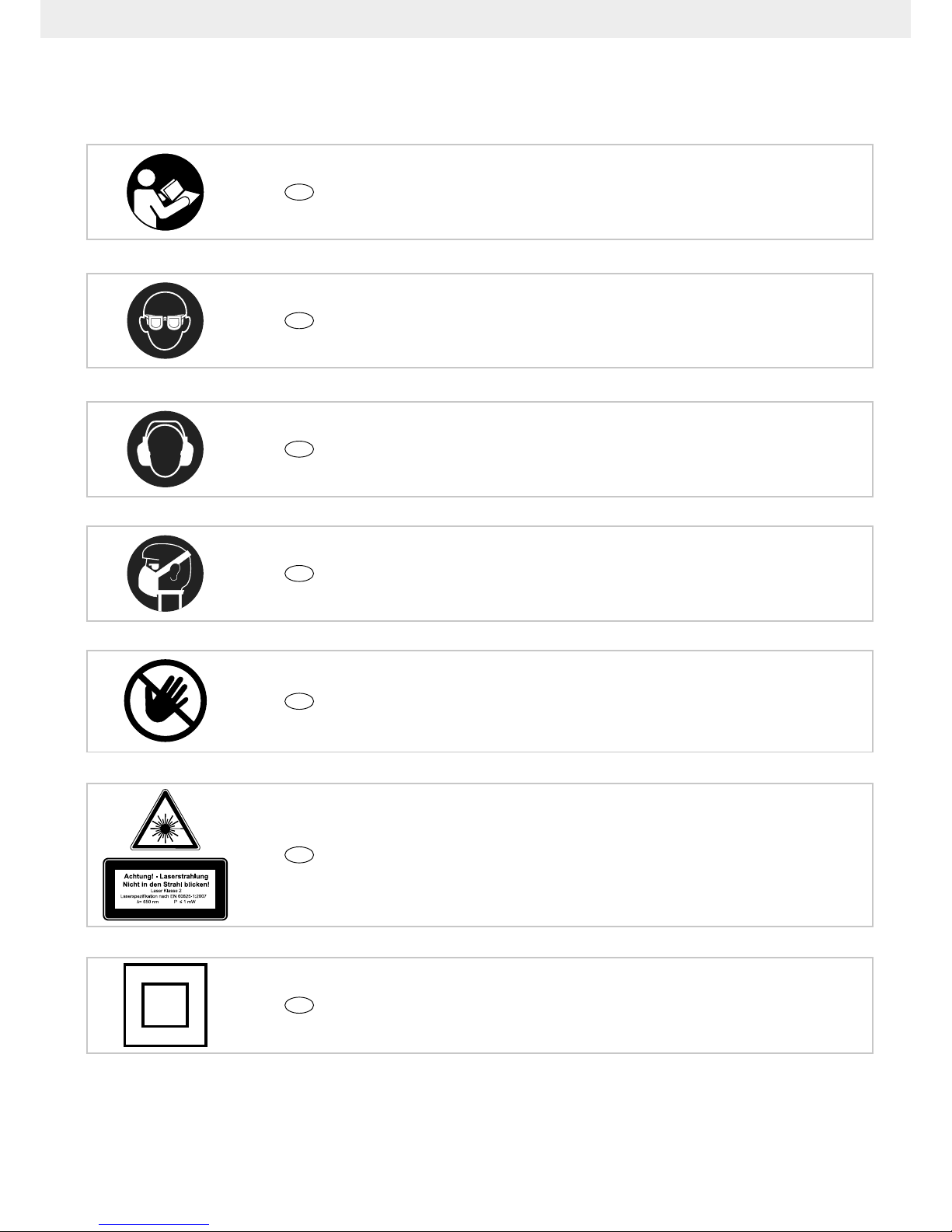
DE
Vor Inbetriebnahme Bedienungsanleitung und Sicherheitshinweise lesen und beachten!
DE
Schutzbrille tragen!
DE
Achtung! Verletzungsgefahr! Nicht in das laufende Sägeblatt greifen!
0
DE
Achtung! Laserstrahlung!
DE
Schutzklasse II
DE
Gehörschutz tragen!
DE
Bei Staubentwicklung Atemschutz tragen!
Erklärung der Symbole auf dem Gerät
7D
Page 8

8 D
1. Einleitung
HERSTELLER:
scheppach
Fabrikation von Holzbearbeitungsmaschine GmbH
Günzburger Straße 69
D-89335 Ichenhausen
VEREHRTER KUNDE,
Wir wünschen Ihnen viel Freude und Erfolg beim Arbeiten mit Ihrem neuen Gerät.
HINWEIS:
Der Hersteller dieses Gerätes haftet nach dem geltenden Produkthaftungsgesetz nicht für Schäden, die an
diesem Gerät oder durch dieses Gerät entstehen bei:
• unsachgemäßer Behandlung,
• Nichtbeachtung der Bedienungsanweisung,
• Reparaturen durch Dritte, nicht autorisierte Fach-
kräfte,
• Einbau und Austausch von nicht originalen Ersatz-
teilen,
• nicht bestimmungsgemäßer Verwendung,
• Ausfällen der elektrischen Anlage bei Nichtbeachtung
der elektrischen Vorschriften und VDE-Bestimmungen 0100, DIN 57113 / VDE0113.
m Achtung!
Beim Benutzen von Geräten müssen einige Sicherheitsvorkehrungen eingehalten werden, um Verletzungen
und Schäden zu verhindern. Lesen Sie diese Bedienungsanleitung / Sicherheitshinweise deshalb sorgfältig durch. Bewahren Sie diese gut auf, damit Ihnen die
Informationen jederzeit zur Verfügung stehen. Falls Sie
das Gerät an andere Personen übergeben sollten, hän-
digen Sie diese Bedienungsanleitung / Sicherheitshin-
weise bitte mit aus. Wir übernehmen keine Haftung für
Unfälle oder Schäden, die durch Nichtbeachten dieser
Anleitung und den Sicherheitshinweisen entstehen.
Zusätzlich zu den Sicherheitsbestimmungen dieser Bedienungsanleitung müssen Sie unbedingt die für den
Be trieb des Elektrowerkzeugs geltenden Vorschriften
Ihres Landes beachten. Bewahren Sie die Bedienungsanleitung, in einer Plas tik hülle geschützt vor Schmutz
und Feuchtigkeit, bei dem Elektrowerkzeug auf. Sie
muss von jeder Bedienungsperson vor Aufnahme der
Arbeit gelesen und sorgfältig beachtet wer den. An dem
Elektrowerkzeug dürfen nur Personen arbeiten, die im
Gebrauch des Elektrowerkzeugs unterwiesen und über
die damit verbundenen Gefahren unterrichtet sind. Das
ge for der te Mindestalter ist einzuhalten.
Neben den in dieser Bedienungsanleitung enthalte-
nen Si cherheitshinweisen und den besonderen Vorschriften Ih res Landes sind die für den Betrieb von
Holzbearbeitungs maschinen allgemein anerkannten
technischen Regeln zu beachten.
2. Gerätebeschreibung (Abb. 1-18)
1. Handgriff
2. Ein-/Ausschalter
2a. Entriegelungsschalter Ein-/Ausschalter
3. Entriegelungshebel
4. Sägewellensperre
5. Maschinenkopf
6. Sägeblattschutz beweglich
7. Sägeblatt
8. Spannvorrichtung
9. Werkstückauage
10. Feststellschraube für Werkstückauage
11. Tischeinlage
12. Raststellungshebel
13. Feststellgriff
14. Zeiger
15. Skala
16. Drehtisch
17. feststehender Sägetisch
18. Anschlagschiene
19. Skala
20. Zeiger
21. Spänefangsack
22. Feststellgriff
23. Feststellschraube für Zugführung
24. Sicherungsbolzen
25. Zugführung
26. Schraube für Schnitttiefenbegrenzung
27. Anschlag für Schnitttiefenbegrenzung
28. Verschiebbare Anschlagschiene
29. Feststellschraube für verschiebbare Anschlag-
schiene
30. Justierschraube (90°)
31. Justierschraube (45°)
32. Flanschschraube
33. Außenansch
34. Laser
35. Ein-/Ausschalter Laser
36. Schraube
37. Innenansch
38. Führungsbügel
39. Kippsicherung
39a. Feststellschraube Kippsicherung
40. Anschlagplatte 90
0
41. Transportgriff
42. Kohlebürsten (beidseitig)
a) 90° Anschlagwinkel (Im Lieferumfang nicht enthalten)
b) 45° Anschlagwinkel (Im Lieferumfang nicht enthalten)
c) Innensechskantschlüssel, 6 mm
3. Lieferumfang
• Öffnen Sie die Verpackung und nehmen Sie das Ge-
rät vorsichtig heraus.
• Entfernen Sie das Verpackungsmaterial sowie Verpa-
ckungs-/ und Transportsicherungen (falls vorhanden).
• Überprüfen Sie, ob der Lieferumfang vollständig ist.
• Kontrollieren Sie das Gerät und die Zubehörteile auf
Transportschäden.
Page 9

9
D
• Bewahren Sie die Verpackung nach Möglichkeit bis
zum Ablauf der Garantiezeit auf.
ACHTUNG
Gerät und Verpackungsmaterialien sind kein Kinderspielzeug! Kinder dürfen nicht mit
Kunststoffbeuteln, Folien und Kleinteilen spielen!
Es besteht Verschluckungs- und
Erstickungsgefahr!
• Zug-, Kapp- und Gehrungssäge
• 1 x Spannvorrichtung (8)
• 2 x Werkstückauage (9)
• Spänefangsack (21)
• Innensechskantschlüssel (c)
• 1 x Kippschutz
• Betriebsanleitung
4. Bestimmungsgemäße Verwendung
Die Zug-, Kapp- und Gehrungssäge dient zum Kappen
von Holz und Kunststoff, entsprechend der Maschinengröße. Die Säge ist nicht zum Schneiden von Brennholz geeignet.
Die Maschine dar f nur nach ihrer Bestimmung ver wendet werden. Jede weitere darüber hinausgehende Verwendung ist nicht bestimmungsgemäß. Für daraus
hervorgerufene Schäden oder Verletzungen aller Art
haftet der Benutzer/Bediener und nicht der Hersteller.
Es dürfen nur für die Maschine geeignete Sägeblätter
verwendet werden. Die Verwendung von Trennscheiben
aller Art ist untersagt.
Bestandteil der bestimmungsgemäßen Verwendung ist
auch die Beachtung der Sicherheitshinweise, sowie die
Montageanleitung und Betriebshinweise in der Bedienungsanleitung.
Personen, die die Maschine bedienen und warten, müssen mit dieser vertraut und über mögliche Gefahren
unterrichtet sein.
Darüber hinaus sind die geltenden Unfallverhütungsvorschriften genauestens einzuhalten.
Sonstige allgemeine Regeln in arbeitsmedizinischen
und sicherheitstechnischen Bereichen sind zu beachten.
Veränderungen an der Maschine schließen eine Haftung des Herstellers und daraus entstehende Schäden
gänzlich aus.
Trotz bestimmungsgemäßer Verwendung können bestimmte Restrisikofaktoren nicht vollständig ausgeräumt
werden. Bedingt durch Konstruktion und Aufbau der
Maschine können folgende Punkte auftreten:
• Berührung des Sägeblattes im nicht abgedeckten
Sägebereich.
• Eingreifen in das laufende Sägeblatt (Schnittverlet-
zung).
• Rückschlag von Werkstücken und Werkstückteilen.
• Sägeblattbrüche.
• Herausschleudern von fehlerhaften Hartmetallteilen
des Sägeblattes.
• Gehörschäden bei Nichtverwendung des nötigen Ge-
hörschutzes.
• Gesundheitsschädliche Emissionen von Holzstäuben
bei Verwendung in geschlossenen Räumen.
Bitte beachten Sie, dass unsere Geräte bestimmungsgemäß nicht für den gewerblichen, handwerklichen oder
industriellen Einsatz konstruiert wurden. Wir übernehmen keine Gewährleistung, wenn das Gerät in Gewerbe-, Handwerks- oder Industriebetrieben sowie bei
gleichzusetzenden Tätigkeiten eingesetzt wird.
5. Wichtige Hinweise
Achtung! Beim Gebrauch von Elektrowerkzeugen sind
zum Schutz gegen elektrischen Schlag, Verletzungsund Brandgefahr folgende grundsätzliche Sicherheitsmaßnahmen zu beachten. Lesen Sie alle diese Hinweise, bevor Sie dieses Elektrowerkzeug benutzen, und
bewahren Sie die Sicherheitshinweise gut auf.
Sicheres Arbeiten
1 Halten Sie Ihren Arbeitsbereich in Ordnung
– Unordnung im Arbeitsbereich kann Unfälle zur
Folge haben.
2 Berücksichtigen Sie Umgebungseinüsse
– Setzen Sie Elektrowerkzeuge nicht dem Regen
aus.
– Benutzen Sie Elektrowerkzeuge nicht in feuchter
oder nasser Umgebung.
– Sorgen Sie für gute Beleuchtung des Arbeitsbe-
reichs.
– Benutzen Sie Elektrowerkzeuge nicht, wo Brand-
oder Explosionsgefahr besteht.
3 Schützen Sie sich vor elektrischem Schlag
– Vermeiden Sie Körperberührung mit geerdeten
Teilen (z. B. Rohren, Radiatoren, Elektroherden,
Kühlgeräten).
4 Halten Sie andere Personen fern.
– Lassen Sie andere Personen, insbesondere Kin-
der, nicht das Elektrowerkzeug oder das Kabel berühren. Halten Sie sie von Ihrem Arbeitsbereich
fern.
5 Bewahren Sie unbenutzte Elektrowerkzeuge si-
cher auf
– Unbenutzte Elektrowerkzeuge sollten an einem
trockenen, hochgelegenen oder abgeschlossenen Ort, außerhalb der Reichweite von Kindern,
abgelegt werden.
6 Überlasten Sie Ihr Elektrowerkzeug nicht
– Sie arbeiten besser und sicherer im angegebenen
Leistungsbereich.
7 Benutzen Sie das richtige Elektrowerkzeug
– Verwenden Sie keine leistungsschwachen Elekt-
rowerkzeuge für schwere Arbeiten.
– Benutzen Sie das Elektrowerkzeug nicht für solche
Zwecke, für die es nicht vorgesehen ist. Benutzen
Sie zum Beis piel kei ne Handkreissäg e zum Sc hneiden von Baumästen oder Holzscheiten.
– Verwenden Sie das Elektrowerkzeug nicht zum
Brennholzsägen.
Page 10

10
D
8 Tragen Sie geeignete Kleidung
– Tragen Sie keine weite Kleidung oder Schmuck, sie
könnten von beweglichen Teilen erfasst werden.
– Bei Arbeiten im Freien ist rutschfestes Schuhwerk
empfehlenswert.
– Tragen Sie bei langen Haaren ein Haarnetz.
9 Benutzen Sie Schutzausrüstung
– Tragen Sie eine Schutzbrille.
– Verwenden Sie bei stauberzeugenden Arbeiten
eine Atemmaske.
10 Schließen Sie die Staubabsaug-Einrichtung an,
wenn Sie Holz, holzähnliche Werkstoffe oder Kunststoffe bearbeitet werden.
– Falls Anschlüsse zur Staubabsaugung und Auf-
fangeinrichtung vorhanden sind, überzeugen Sie
sich, dass diese angeschlossen und richtig benutzt werden.
– Der Betrieb in geschlossenen Räumen ist beim
Bearbeiten von Holz, holzähnlichen Werkstoffen
und Kunststoffen nur mit einer geeigneten Absauganlage zulässig.
11 Verwenden Sie das Kabel nicht für Zwecke, für
die es nicht bestimmt ist
– Benutzen Sie das Kabel nicht, um den Stecker aus
der Steckdose zu ziehen. Schützen Sie das Kabel
vor Hitze, Öl und scharfen Kanten.
12 Sichern Sie das Werkstück
– Benutzen Sie Spannvorrichtungen oder einen
Schraubstock, um das Werkstück festzuhalten.
Es ist damit sicherer gehalten als mit Ihrer Hand
und ermöglicht die Bedienung der Maschine mit
beiden Händen.
– Bei langen Werkstücken ist eine zusätzliche Aua-
ge (Tisch, Bö cke, etc.) er forderlich, um ein Kippen
der Maschine zu vermeiden.
– Drücken Sie das Werkstück immer fest gegen Ar-
beitsplatte und Anschlag, um ein Wackeln bzw.
Verdrehen des Werkstückes zu verhindern.
13 Vermeiden Sie abnormale Körperhaltung
– Sorgen Sie für sicheren Stand und halten Sie je-
derzeit das Gleichgewicht.
– Vermeiden Sie ungeschickte Handpositionen, bei
denen durch ein plötzliches Abrutschen eine oder
beide Hände das Sägeblatt berühren könnten.
14 Pegen Sie Ihre Werkzeuge mit Sorgfalt
– Halten Sie die Schneidwerkzeuge scharf und sau-
ber, um besser und sicherer arbeiten zu können.
– Befolgen Sie die Hinweise zur Schmierung und
zum Werkzeugwechsel.
– Kontrollieren Sie regelmäßig die Anschlussleitung
des Elektrowerkzeugs und lassen Sie diese bei
Beschädigung von einem anerkannten Fachmann
erneuern.
– Kontrollieren Sie Verlängerungsleitungen regel-
mäßig und ersetzen Sie diese, wenn sie beschädigt sind.
– H alte n Sie Handgri ffe tro cken, sauber und frei von
Öl und Fett.
15 Ziehen Sie den Stecker aus der Steckdose
– Entfernen Sie nie lose Splitter, Späne oder einge-
klemmte Holzteile bei laufendem Sägeblatt.
– Bei Nichtgebrauch des Elektrowerkzeugs, vor der
Wartung und beim Wech sel von Werkzeu gen wie
z. B. Sägeblatt, Bohrer, Fräser.
– Wenn das Sägeblatt beim Schneiden durch eine
zu große Vorschubkraft blockiert, schalten Sie das
Gerät aus und trennen Sie es vom Netz. Entfernen
Sie das Werkstück und stellen Sie sicher, dass
das Sägeblatt frei läuft. Schalten Sie das Gerät
ein, und führen Sie den Schnittvorgang er ne ut mit
reduzierter Vorschubkraft durch.
16 Lassen Sie keine Werkzeugschlüssel stecken
– Ü berprüfen Sie vor dem Einschalten, dass Sc hlüs-
sel und Einstellwerkzeuge entfernt sind.
17 Vermeiden Sie unbeabsichtigten Anlauf
– Vergewissern Sie sich, dass der Schalter beim
Einstecken des Steckers in die Steckdose ausgeschaltet ist.
18 Benutzen Sie Verlängerungskabel für den Au-
ßenbereich
– Verwenden Sie im Freien nur dafür zugelassene
und entsprechend gekennzeichnete Verlängerungskabel.
– Verwenden Sie die Kabeltrommel nur im abge-
rollten Zustand.
19 Seien Sie stets aufmerksam
– Achten Sie darauf, was Sie tun. Gehen Sie mit
Vernunft an die Arbeit. Benutzen Sie das Elektrowerkzeug nicht, wenn Sie unkonzentriert sind.
20 Überprüfen Sie das Elektrowerkzeug auf even-
tuelle Beschädigungen
– Vor weiterem Gebrauch des Elektrowerkzeugs
müssen Schutzvorrichtungen oder leicht beschädigte Teile sorgfältig auf ihre einwan dfreie und be stimmungsgemäße Funktion untersucht werden.
– Überprüfen Sie, ob die beweglichen Teile ein-
wandfrei funktionieren und nicht klemmen oder
ob Teile beschädigt sind. Sämtliche Teil e müssen
richtig montiert sein und alle Bedingungen erfüllen, um den einwandfreien Betrieb des Elektrowerkzeugs zu gewährleisten.
– Die bewegliche Schutzhaube darf in geöffnetem
Zustand nicht festgeklemmt werden.
– Beschädigte Schutzvorrichtungen und Teile müs-
sen bestimmungsgemäß durch eine anerkannte
Fachwerkstatt repariert oder ausgewechselt werden, soweit nichts anderes in der Bedienungsanleitung angegeben ist.
– Beschädigte Schalter müssen bei einer Kunden-
dienstwerkstatt ersetzt werden.
– Benutzen Sie keine fehlerhaften oder beschädig-
ten Anschlussleitungen.
– Benutzen Sie keine Elektrowerkzeuge, bei denen
sich der Schalter nicht ein- und ausschalten lässt.
21 ACHTUNG!
– Bei Doppelgehrungsschnitten ist besondere Vor-
sicht geboten.
22 ACHTUNG!
– Der Gebrauch anderer Einsatzwerkzeuge und
anderen Zubehörs kann eine Verletzungsgefahr
für Sie bedeuten.
Page 11

11
D
23 Lassen Sie Ihr Elektrowerkzeug durch eine Elek-
trofachkraft reparieren
– Dieses Elektrowerkzeug entspricht den einschlä-
gigen Sicherheitsbestimmungen. Reparaturen
dürfen nur von einer Elektrofachkraft ausgeführt
werden, indem Originalersatzteile verwendet werden; anderenfalls können Unfälle für den Benutzer
entstehen.
ZUSÄTZLICHE SICHERHEITSHINWEISE
1 Sicherheitsvorkehrungen
– Warnung! Beschädigte oder deformierte Säge-
blätter nicht verwenden.
– Tauschen Sie einen abgenutzten Tischeinsatz
aus.
– Verwenden Sie nur vom Hersteller empfohlene
Sägeblätter, die EN 847-1 entsprechen.
– Achten Sie darauf, dass ein für den zu schne iden-
den Werkstoff geeignetes Sägeblatt ausgewählt
wird.
– Tragen Sie eine geeignete persönliche Schutz-
ausrüstung. Dies schließt ein:
– Gehörschutz zur Verminderung des Risikos
schwerhörig zu werden,
– Atemschutz zur Verminderung des Risikos ge-
fährlichen Staub einzuatmen,
– Tragen Sie beim Hantieren mit Sägeblättern
und rauen Werkstoffen Handschuhe. Tragen
Sie Sägeblätter, wann immer praktikabel, in
einem Behältnis.
– Tragen Sie eine Schutzbrille. Während der Ar-
beit entstehende Funken oder aus dem Gerät
heraustretende Splitter, Späne und Stäube
können Sichtverlust bewirken.
– Schließen Sie das Elektrowerkzeug beim Sägen
von Holz an eine Staubauffangeinrichtung an. Die
Staubfreisetzung wird unter anderem durch die Art
des zu bearbeitenden Werkstoffs und die richtige
Einstellung von Hauben/Leitblechen/Führungen
beeinusst.
– Verwenden Sie keine Sägeblätter aus hochlegier-
tem Schnellarbeitsstahl (HSS-Stahl).
2 Wartung und Instandhaltung
– Ziehen Sie bei jeglichen Einstell- und Wartungs-
arbeiten den Netzstecker.
– Die Lärmbelastung wird von verschiedenen Fak-
toren beeinusst, unter anderem von der Beschaffenheit der Sägeblätter, Zustand von Sägeblatt und Elektrowerkzeug. Verwenden Sie nach
Möglichkeit Sägeblätter, die zur Verringerung der
Geräuschentwicklung konstruiert wurden, warten
Sie das Elektrowerkzeug und Werkzeugaufsätze
regelmäßig und setzen Sie diese gegebenenfalls
instand, um Lärm zu reduzieren.
– Melden Sie Fehler an dem Elektrowerkzeug,
Schutzeinrichtungen oder dem Werkzeugaufsatz
sobald diese entdeckt wurden, der für die Sicherheit verantwortlichen Person.
3 Sicheres Arbeiten
– Verwenden Sie nur Sägeblätter, deren höchstzu-
lässige Drehzahl nicht geringer ist als die maximale Spindeldrehzahl de r Säge und die für den zu
schneidenden Werkstoff geeignet sind.
– Vergewissern Sie sich, dass das Sägeblatt in
keiner Stellung den Drehtisch berührt, indem Sie
bei gezogenem Netzstecker das Sägeblatt mit der
Hand, in der 45° und in der 90° Stellung drehen.
Sägekopf gegebenenfalls neu justieren.
– Verwenden Sie beim Transportieren des Elekt-
rowerkzeuges nur die Transportvorrichtungen.
Verwenden Sie niemals die Schutzvorrichtungen
für Handhabung oder Transport.
– Achten Sie darauf, dass während des Transportes
der untere Teil des Sägeblattes abgedeckt ist, beispielsweise durch die Schutzvorrichtung.
– Darauf achten, nur solche Distanzscheiben und
Spindelringe zu verwenden, die für den vom Hersteller angegebenen Zweck geeignet sind.
– Der Fußboden im Umkreis der Maschine muss
eben, sauber und frei von losen Partikeln, wie z.
B. Spänen und Schnittresten, sein.
– Arbeitsstellung stets seitlich vom Sägeblatt.
– Keine Schnittreste oder sonstige Werkstückteile
aus dem Schnittbereich entfernen, so lange die
Maschine läuft und das Sägeaggregat sich noch
nicht in der Ruhestellung bendet.
– Darauf achten, dass die Maschine, wenn irgend
möglich, immer an einer Werkbank oder einem
Tisch befestigt ist.
– Lange Werkstücke gegen Abkippen am Ende des
Schneidvorgangs sichern (z. B. Abrollständer oder
Rollbock).
Warnung! Dieses Elektrowerkzeug erzeugt während
des Betriebs ein elektromagnetisches Feld. Dieses Feld
kann unter bestimmten Umständen aktive oder passive
medizinische Implantate beeinträchtigen. Um die Gefahr von ernsthaften oder tödlichen Verletzungen zu
verringern, empfehlen wir Personen mit medizinischen
Implantaten ihren Arzt und den Hersteller vom medizinischen Implantat zu konsultieren, bevor das Elektrowerkzeug bedient wird.
SICHERHEITSHINWEISE FÜR DEN UMGANG MIT
SÄGEBLÄTTERN
1 Setzen Sie nur Einsatzwerkzeuge ein, wenn Sie den
Umgang damit beherrschen.
2 Beachten Sie die Höchstdrehzahl. Die auf dem Ein-
satzwerkzeug angegebene Höchstdrehzahl darf
nicht überschritten werden. Halten Sie, falls angegeben, den Drehzahlbereich ein.
3 Beachten Sie die Motor- Sägeblatt- Drehrichtung.
4 Verwenden Sie keine Einsatzwerkzeuge mit Rissen.
Mustern Sie gerissene Einsatzwerkzeuge aus. Eine
Instandsetzung ist nicht zulässig.
5 Reinigen Sie die Spannächen von Verschmutzun-
gen, Fett, Öl und Wasser.
Page 12
12
D
6 Verwenden Sie keine losen Reduzierringe oder
-buchsen zum Reduzieren von Bohrungen bei Kreissägeblättern.
7 Achten Sie darauf, dass xierte Reduzierringe
zum Sichern des Einsatzwerkzeuges den gleichen
Durchmesser und mindestens 1/3 des Schnittdurch-
messers haben.
8 Stellen Sie sicher, dass xierte Reduzierringe par-
allel zueinander sind.
9 Handhaben Sie Einsatzwerkzeuge mit Vorsicht.
Bewahren Sie diese am besten in der Originalverpackung oder speziellen Behältnissen auf. Tragen
Sie Schutzhandschuhe, um die Griffsicherheit zu
verbessern und das Verletzungsrisiko weiter zu
mindern.
10 Stellen Sie vor der Benutzung von Einsatzwerkzeu-
gen sicher, dass alle Schutzvorrichtungen ordnungsgemäß befestigt sind.
11 Vergewissern Sie sich vor dem Einsatz, dass das
von Ihnen benutzte Einsatzwerkzeug den technischen Anforderungen dieses Elektrowerkzeuges
entspricht und ordnungsgemäß befestigt ist.
12 Benutzen Sie das mitgelieferte Sägeblatt nur für
Sägearbeiten in Holz, holzähnlichen Werkstoffen,
Kunststoffen und Buntmetallen (außer Magnesium
und magnesiumhaltige Legierungen).
13 Verwenden Sie die Säge niemals zum Schneiden
anderer als der festgelegten Werkstoffe.
14 Achten Sie darauf, dass die Maschine vor jedem
Sägevorgang sicher steht.
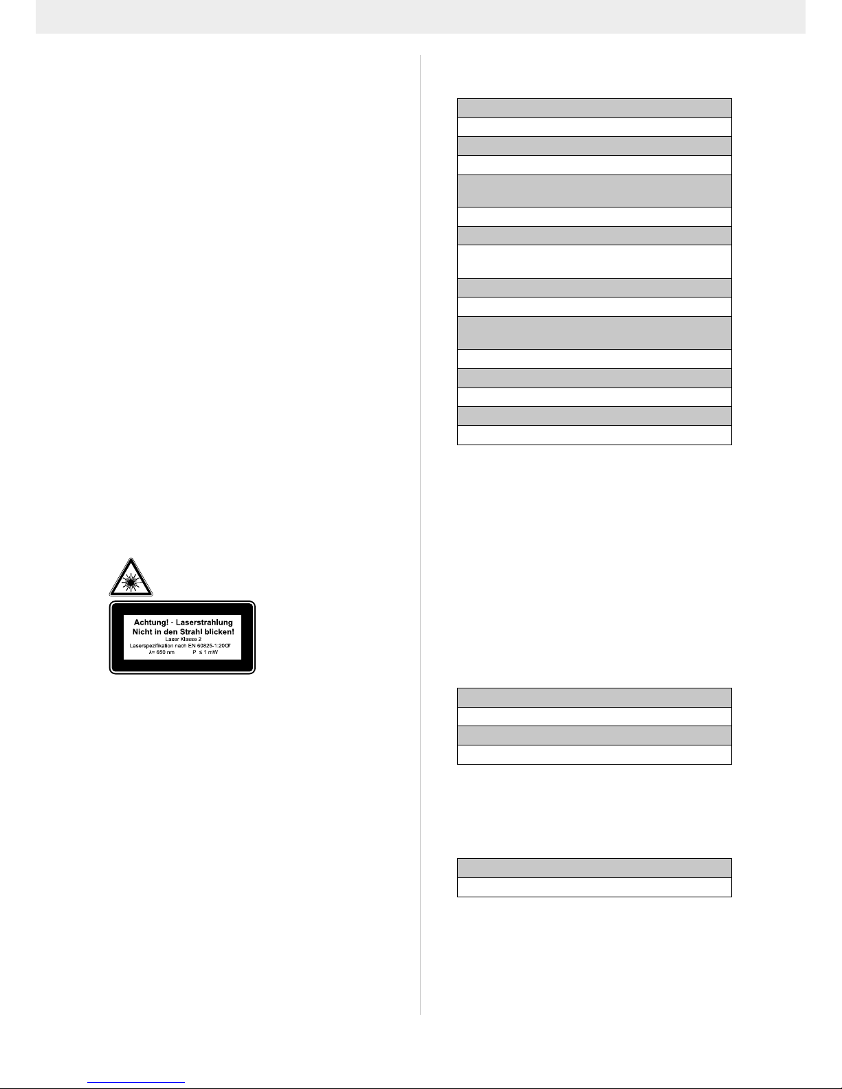
Achtung: Laserstrahlung
Nicht in den Strahl blicken
Laserklasse 2
Schützen Sie sich und Ihre Umwelt durch geeignete
Vorsichtsmaßahmen vor Unfallgefahren!
• Nicht direkt mit ungeschütztem Auge in den Laser-
strahl blicken.
• Niemals direkt in den Strahlengang blicken.
• Den Laserstrahl nie auf reektierende Flächen und
Personen oder Tiere richten. Auch ein Laserstrahl
mit geringer Leistung kann Schäden am Auge verursachen.
• Vorsicht - wenn andere als die hier angegebenen Ver-
fahrensweisen ausgeführt werden, kann dies zu einer
gefährlichen Strahlungsexposition führen.
• Lasermodul niemals öffnen. Es könnte unerwartet zu
einer Strahlenexposition kommen.
• Wenn die Kappsäge längere Zeit nicht benutzt wird,
sollten die Batterien entfernt werden.
• Der Laser darf nicht gegen einen Laser anderen
Typs ausgetauscht werden.
• Reparaturen am Laser dür fen nur vom Hersteller des
Lasers oder einem autorisierten Vertreter vorgenommen werden.
0
6. Technische Daten
Wechselstrommotor 230 V~ 50Hz
Leistung 2000 Watt
Betriebsart S6 25% *
Leerlaufdrehzahl 4200 min
-1
Hartmetallsägeblatt
ø 305 x ø 30 x 3,0 mm
Anzahl der Zähne 60
Schwenkbereich -45° / 0°/ +45°
Gehrungsschnitt
0° bis 45°
(links / rechts)
Sägebreite bei 90° 340 x 90 mm
Sägebreite bei 45° 240 x 90 mm
Sägebreite bei 2 x 45°
(Doppelgehrungsschnitt)
240 x 55 mm
Schutzklasse II
Gewicht (inkl. Zubehör) 23,0 kg
Laserklasse 2
Wellenlänge Laser 650 nm
Leistung Laser < 1 mW
* Betriebsart S6 25%, ununterbrochener periodischer
Betrieb. Der Betrieb setzt sich aus einer Anlaufzeit, einer Zeit mit konstanter Belastung und einer Leerlaufzeit
zusammen. Die Spieldauer beträgt 10 min,
die relative Einschaltdauer beträgt 25% der Spieldauer.
Das Werkstück muss mindestens eine Höhe von 3
mm und eine Breite von 10 mm haben.
Achten Sie darauf, dass das Werkstück immer mit
der Spannvorrichtung gesichert wird.
Geräusch und Vibration
Die Geräusch- und Vibrationswerte wurden entsprechend EN 61029 ermittelt.
Schalldruckpegel L
pA
99,9 dB(A)
Unsicherheit K
pA
3 dB
Schallleistungspegel L
WA
112,9 dB(A)
Unsicherheit K
WA
3 dB
Tragen Sie einen Gehörschutz.
Die Einwirkung von Lärm kann Gehörverlust bewirken.
Schwingungsgesamtwerte (Vektorsumme dreier Richtungen) ermittelt entsprechend EN 61029.
Schwingungsemissionswert a
h
2,091 m/s²
Unsicherheit K 1,5 m/s²
Der angegebene Schwingungsemissionswert ist nach
einem genormten Prüfverfahren gemessen worden und
kann zum Vergleich eines Elektrowerkzeugs mit einem
anderen verwendet werden;
Der angegebene Schwingungsemissionswert kann
auch zu einer ersten Beurteilung der Belastung verwendet werden.
Page 13

13
D
Warnung:
Der Schwingungsemissionswert kann sich während der
tatsächlichen Benutzung des Elektrowerkzeugs von
dem Angabewert unterscheiden, abhängig von der Art
und Weise, in der das Elektrowerkzeug verwendet wird;
Versuchen Sie, die Belastung durch Vibrationen so
gering wie möglich zu halten. Beispielhafte Maßnahmen zur Verringerung der Vibrationsbelastung sind das
Tragen von Handschuhen beim Gebrauch des Werkzeugs und die Begrenzung der Arbeitszeit. Dabei sind
alle Anteile des Betriebszyklus sind zu berücksichtigen
(beispielsweise Zeiten, in denen das Elektrowerkzeug
abgeschaltet ist, und solche, in denen es zwar eingeschaltet ist, aber ohne Belastung läuft).
Restrisiken
Das Elektrowerkzeug ist nach dem Stand der Technik und den anerkannten sicherheitstechnischen
Regeln gebaut. Dennoch können beim Arbeiten einzelne Restrisiken auftreten.
• Gefährdung der Gesundheit durch Strom bei Verwendung nicht ordnungsgemäßer Elektro-Anschlussleitungen.
• Desweiteren können trotz aller getroffener Vorkehrungen nicht offensichtliche Restrisiken bestehen.
• Restrisiken können minimiert werden, wenn die „Sicherheitshinweise“ und die „Bestimmungsgemäße Verwendung“, sowie die Bedienungsanweisung
insge samt beachtet werden.
• Belasten Sie die Maschine nicht unnötig: zu starker
Druck beim Sägen beschädigt das Sägeblatt schnell.
Dies kann zu einer Leistungsverminderung der Maschine bei der Verarbeitung und einer Verminderung
der Schnittgenauigkeit führen.
• Beim Schneiden von Plastikmaterial verwenden Sie
bitte immer Klemmen: die Teile, die gesägt werden
sollen, müssen immer zwischen den Klemmen xiert
werden.
• Vermeiden Sie zufällige Inbetriebsetzungen der Maschine: beim Einführen des Steckers in die Steckdose
darf die Betriebstaste nicht gedrückt werden.
• Verwenden Sie das Werkzeug, das in diesem Handbuch empfohlen wird. So erreichen Sie, dass Ihre
Kappsäge optimale Leistungen erbringt.
• Halten Sie Ihre Hände vom Arbeitsbereich fern, wenn
die Maschine in Betrieb ist.
• Bevor Sie Einstell- oder Wartungsarbeiten vornehmen, lassen Sie die Starttaste los und ziehen den
Netzstec ker.
7. Vor Inbetriebnahme
• Die Maschine muss standsicher aufgestellt werden,
d.h. auf einer Werkbank, dem Untergestell o. ä. festschrauben. Verwenden Sie dazu die Bohrungen, die
sich im Gestell der Maschine benden.
• Vor Inbetriebnahme müssen alle Abdeckungen und Sicherheitsvorrichtungen ordnungsgemäß montiert sein.
• Das Sägeblatt muss frei laufen können.
• Bei bereits bearbeitetem Holz auf Fremdkörper, wie
z.B. Nägel oder Schrauben, usw. achten.
• Bevor Sie den Ein-/Ausschalter betätigen, vergewis-
sern Sie sich, ob das Sägeblatt richtig montiert ist
und bewegliche Teile leichtgängig sind.
• Überzeugen Sie sich vor dem Anschließen der Ma-
schine, dass die Daten auf dem Typenschild mit den
Netzdaten übereinstimmen.
8. Aufbau und Bedienung
8.1 Säge aufbauen (Abb.1/2/6a-c)
• Zum Verstellen des Drehtisches (16) den Feststell-
griff (13) im Uhrzeigersinn drehen um die Arretierung
zu lösen.
• Raststellungshebel (12) mit dem Zeigenger nach
oben ziehen.
• Drehtisch (16) und Zeiger (14) auf das gewünschte
Winkelmaß der Skala (15) einstellen und durch drehen des Feststellgriffs (13) entgegen dem Uhrzeigersinn, xieren.
• Durch leichtes Drücken des Maschinenkopfes (5)
nach unten und gleichzeitiges Herausziehen des Sicherungsbolzens (24) aus der Motorhalterung, wird
die Säge aus der unteren Stellung entriegelt.
• Maschinenkopf (5) nach oben schwenken, bis der
Entriegelungshebel (3) einrastet.
• Die Spannvorrichtung (8) kann sowohl links als auch
rechts an dem feststehenden Sägetisch (17) befestigt
werden. Stecken Sie die Spannvorrichtung (8) in die
dafür vorgesehene Bohrung an der Hinterseite der
Anschlagschiene (18).
• Werkstückauagen (9) an dem feststehenden Säge-
tisch (17) wie in Abbildung 6a,b,c gezeigt anbringen und komplett durchschieben. Die Wellen mit
den Schrauben gegen ein unbeabsichtigtes Heraus-
rutschen sichern. Danach mit der Schraube (10) auf
gewünschter Stellung xieren.
• Kippsicherung (39) an dem feststehenden Sägetisch
(17) wie in Abbildung 6c gezeigt anbringen. Die Wel-
len mit Schraube (39a) gegen ein unbeabsichtigtes
Herausrutschen sichern.
• Der Maschinenkopf (5) kann durch Öffnen des Fest-
stellgriffes (22), nach links oder rechts auf max. 45°
geneigt werden.
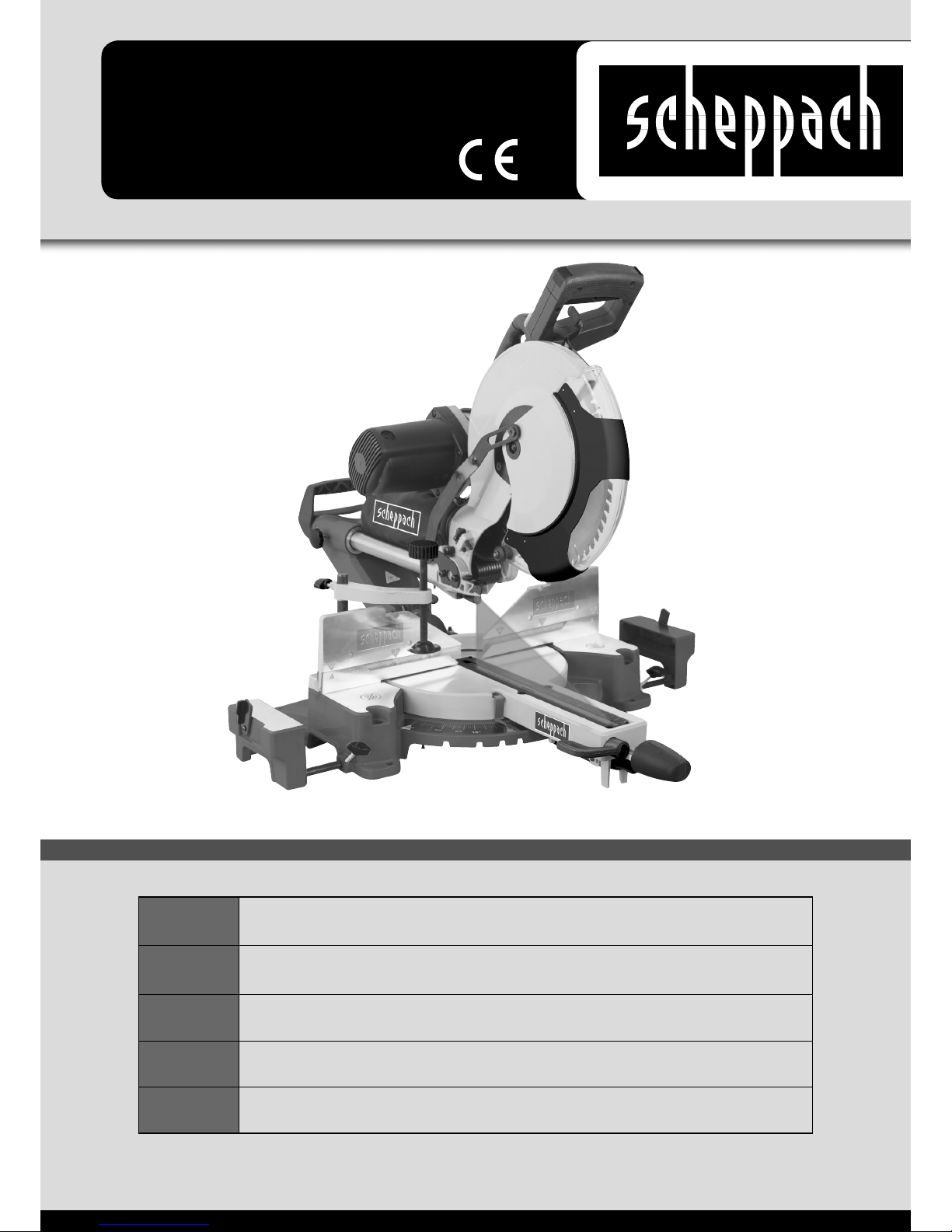
8.2 Feinjustierung des Anschlags für Kappschnitt
90° (Abb. 1/2/5/7/8)
• Anschlagwinkel (a) nicht im Lieferumfang ent-
halten.
• Den Maschinenkopf (5) nach unten senken und mit
dem Sicherungsbolzen (24) xieren.
• Feststellgriff (22) lockern.
• Anschlagwinkel (a) zwischen Sägeblatt (7) und Dreh-
tisch (16) anlegen.
• Anschlagplatte 90
0
(40) nach oben klappen
• Gegenmutter (Abb.8 Pos. d) lockern. Die Justier-
schraube (30) soweit verstellen, bis der Winkel zwischen Sägeblatt (7) und Drehtisch (16) 90° beträgt.
• Gegenmutter (d) wieder festziehen, um diese Einstel-
lung zu xieren.
Page 14

14
D
• Überprüfen Sie abschließend die Position der Win-
kelanzeige. Falls erforderlich, Zeiger (20) mit Kreuzschlitzschraubendreher lösen, auf 0°-Position der
Winkelskala (19) setzen und Halteschraube wieder
festziehen.
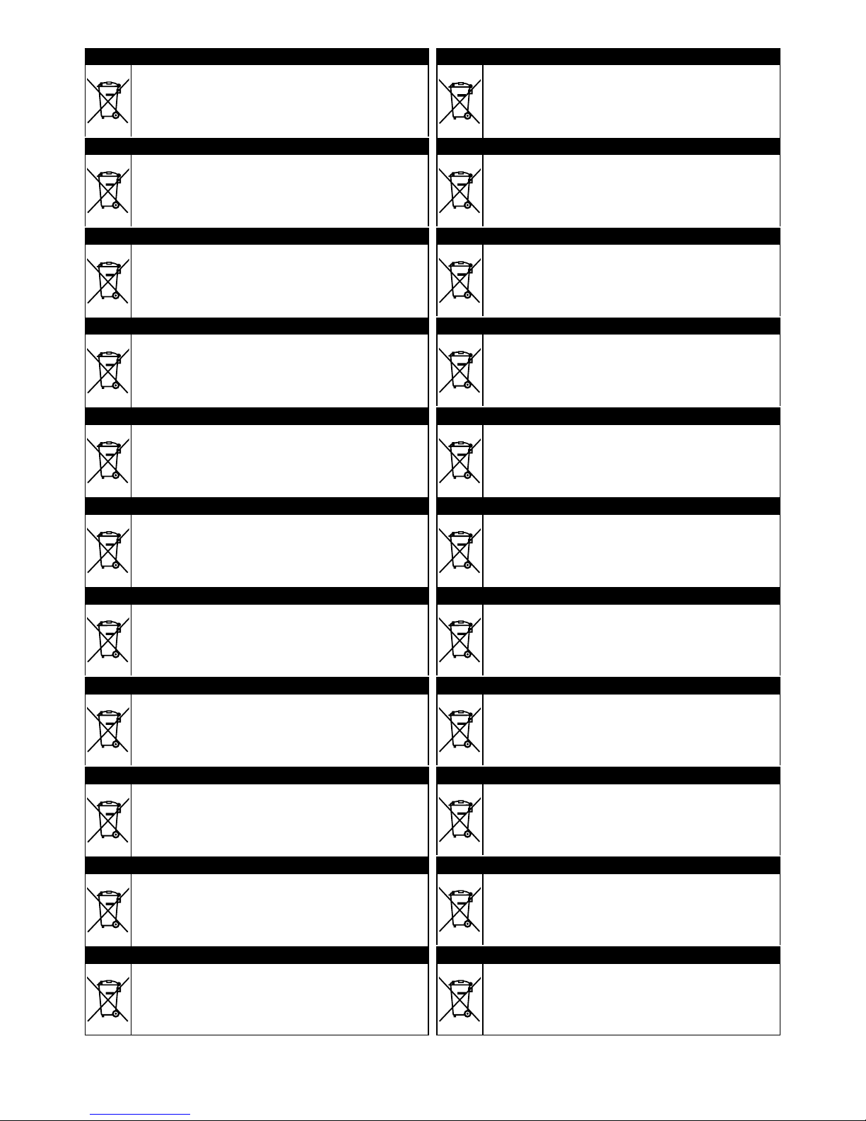
8.3 Feinjustierung des Anschlags für Gehrungsschnitt +45°/-45° (Abb. 1/2/5/9/10)
• Anschlagwinkel (b) nicht im Lieferumfang ent-
halten.
• Den Maschinenkopf (5) nach unten senken und mit
dem Sicherungsbolzen (24) xieren.
• Den Drehtisch (16) auf 0° Stellung xieren.
• Die Feststellschraube (22) lösen und mit dem Hand-
griff (1) den Maschinenkopf (5) nach links oder rechts,
auf 45° neigen.
• 45°-Anschlagwinkel (b) zwischen Sägeblatt (7) und
Drehtisch (16) anlegen.
• Gegenmuttern (c) lockern. Justierschrauben (31) so-
weit verstellen, bis der Winkel zwischen Sägeblatt (7)
und Drehtisch (16) genau +45°/-45° beträgt.
• Gegenmuttern (c) wieder festziehen, um diese Ein-
stellung zu xieren.
8.4 Kappschnitt 90° und Drehtisch 0° (Abb.1/2/11/12)
Bei Schnittbreiten bis ca. 100 mm kann die Zugfunktion
der Säge mit der Feststellschraube (23) in der hinteren
Position xiert werden. In dieser Position kann die Maschine im Kapp-Betrieb betrieben werden. Sollte die
Schnittbreite über 100 mm liegen, muss darauf geachtet
werden, dass die Feststellschraube (23) locker und der
Maschinenkopf (5) beweglich ist.
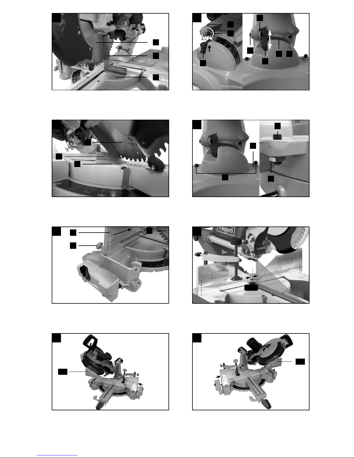
Achtung! Die verschiebbare Anschlagschiene (28)
muss für 90° - Kappschnitte in der inneren Position
beidseitig xiert werden. (siehe Abb. 11)
• Öffnen Sie die Feststellschraube (29) der verschieb-
baren Anschlagschiene (28) und schieben Sie die
verschiebbare Anschlagschiene (28) nach innen.
• Die verschiebbare Anschlagschiene (28) muss soweit
vor der innersten Position arretiert werden, dass der
Abstand zwischen Anschlagschiene (28) und Sägeblatt (7) maximal 8 mm beträgt. (siehe Abb. 12)
• Prüfen Sie vor dem Schnitt, dass zwischen der An-
schlagschiene (28) und dem Sägeblatt (7) keine Kollision möglich ist.
• Feststellschraube (29) wieder anziehen.
• Maschinenkopf (5) in die obere Position bringen.
• Maschinenkopf (5) am Handgriff (1) nach hinten
schieben und gegebenenfalls in dieser Position xieren (je nach Schnittbreite).
• Legen Sie das zu schneidende Holz an die Anschlag-
schiene (18) und auf den Drehtisch (16).
• Das Material mit der Spannvorrichtung (8) auf dem
feststehenden Sägetisch (17) feststellen, um ein Verschieben während des Schneidvorgangs zu verhindern.
• Entriegelungshebel (3) drücken um den Maschinen-
kopf (5) freizugeben.
• Ein-, Ausschalter (2) und Entriegelungsschalter (2a)
gedrückt halten um den Motor einzuschalten.
• Bei xierter Zugführung (23):
Maschinenkopf (5) mit dem Handgriff (1) gleichmäßig und mit leichtem Druck nach unten bewegen,
bis das Sägeblatt (7) das Werkstück durchschnitten
hat.
• Bei nicht xierter Zugführung (23):
Maschinenkopf (5) nach ganz vorne ziehen. Den
Handgriff (1) gleichmäßig und mit leichtem Druck
ganz nach unten absenken. Nun Maschinenkopf (5)
langsam und gleichmäßig ganz nach hinten schieben, bis das Sägeblatt (7) das Werkstück vollständig durchschnitten hat.
• Nach Beendigung des Sägevorgangs Maschinen-
kopf wieder in die obere Ruhestellung bringen und
Ein,- Ausschalter (2) loslassen.
Achtung! Durch die Rückholfeder schlägt die Maschine automatisch nach oben. Handgriff (1) nach
Schnittende nicht loslassen, sondern Maschinenkopf langsam und unter leichtem Gegendruck nach
oben bewegen.
8.5 Kappschnitt 90° und Drehtisch 0°- 45°
(Abb. 1/2/11/12)
Mit der Kappsäge können Schrägschnitte nach links
und rechts von 0°- 45° zur Anschlagschiene ausgeführt
werden.
Achtung! Die verschiebbare Anschlagschiene (28)
muss für 90° - Kappschnitte in der inneren Position
beidseitig xiert werden. (siehe Abb. 11)
• Öffnen Sie die Feststellschraube (29) der verschieb-
baren Anschlagschiene (28) und schieben Sie die
verschiebbare Anschlagschiene (28) nach innen.
• Die verschiebbare Anschlagschiene (28) muss soweit
vor der innersten Position arretiert werden, dass der
Abstand zwischen Anschlagschiene (28) und Sägeblatt (7) maximal 8 mm beträgt. (siehe Abb. 12)
• Prüfen Sie vor dem Schnitt, dass zwischen der An-
schlagschiene (28) und dem Sägeblatt (7) keine Kollision möglich ist.
• Feststellschraube (29) wieder anziehen.
• Den Feststellgriff (13) entgegen dem Uhrzeigersinn
lösen und den unteren Raststellungshebel (12) mit
dem Zeigenger nach oben ziehen.
• Mit dem Feststellgriff (13) den Drehtisch (16) auf den
gewünschten Winkel einstellen. Der Zeiger (14) auf
dem Drehtisch (16) muss mit dem gewünschtem Winkelmaß der Skala (15) auf dem feststehenden Sägetisch (17) übereinstimmen.
• Den Feststellgriff (13) im Uhrzeigersinn drehen um
den Drehtisch (16) zu xieren.
• Schnitt wie unter Punkt 8.4 beschrieben ausführen.
8.6 Gehrungsschnitt 0°- 45° und Drehtisch 0°
(A bb. 1/2/11-14)
Mit der Kappsäge können Gehrungsschnitte nach links/
rechts von 0°- 45° zur Arbeitsäche ausgeführt werden.
Achtung! Die verschiebbare Anschlagschiene
(28a/28b) muss für Gehrungschnitte (geneigter
Sägekopf) in der äußeren Position xiert werden.
Page 15

15
D
• Öffnen Sie den Feststellgriff (29) der verschiebba-
ren Anschlagschiene (28) und schieben Sie die verschiebbare Anschlagschiene (28) auf der Seite der
Neigung (siehe Abb. 13+14) nach außen.
• Die andere verschiebbare Anschlagschiene (28)
muss soweit vor der innersten Position arretiert werden, dass der Abstand zwischen Anschlagschiene
(28) und Sägeblatt (7) mindestens 8 mm beträgt. (siehe Abb. 12)
• Prüfen Sie vor dem Schnitt, dass zwischen der An-
schlagschiene (28) und dem Sägeblatt (7) keine Kollision möglich ist.
• Feststellschraube (29) wieder anziehen.
• Maschinenkopf (5) in die obere Stellung bringen.
• Den Drehtisch (16) auf 0° Stellung xieren.
• Die Feststellschraube (22) lösen und mit dem Hand-
griff (1) den Maschinenkopf (5) nach links/rechts neigen, bis der Zeiger (20) auf das gewünschte Winkelmaß an der Skala (19) zeigt.
• Feststellschraube (22) wieder festziehen.
• Schnitt wie unter Punkt 8.4 beschrieben durchführen.
8.7 Gehrungsschnitt 0°- 45° und Drehtisch 0°- 45°
(Abb. 1-2/11-14)
Mit der Kappsäge können Gehrungsschnitte nach links/
rechts von 0°- 45° zur Arbeitsäche und gleichzeitig
0°- 45° zur Anschlagschiene ausgeführt werden (Doppelgehrungsschnitt).
Achtung! Die verschiebbare Anschlagschiene (28)
muss für Gehrungschnitte (geneigter Sägekopf) in
der äußeren Position xiert werden.
• Öffnen Sie den Feststellgriff (29) der verschiebbaren
Anschlagschiene (28a/28b) und schieben Sie die verschiebbare Anschlagschiene (28) auf der Seite der
Neigung (siehe Abb. 13+14) nach außen.
• Die andere verschiebbare Anschlagschiene (28)
muss soweit vor der innersten Position arretiert werden, dass der Abstand zwischen Anschlagschiene
(28) und Sägeblatt (7) mindestens 8 mm beträgt. (siehe Abb. 12)
• Prüfen Sie vor dem Schnitt, dass zwischen der An-
schlagschiene (28) und dem Sägeblatt (7) keine Kollision möglich ist.
• Feststellschraube (29) wieder anziehen.
• Maschinenkopf (5) in die obere Stellung bringen.
• Den Feststellgriff (13) entgegen dem Uhrzeigersinn
lösen und den unteren Raststellungshebel (12) mit
dem Zeigenger nach oben ziehen.
• Mit dem Feststellgriff (13) den Drehtisch (16) auf den
gewünschten Winkel einstellen. Der Zeiger (14) auf
dem Drehtisch (16) muss mit dem gewünschtem Winkelmaß der Skala (15) auf dem feststehenden Sägetisch (17) übereinstimmen.
• Den Feststellgriff (13) im Uhrzeigersinn drehen um
den Drehtisch (16) zu xieren.
• Die Feststellschraube (22) lösen.
• Mit dem Handgriff (1) den Maschinenkopf (5) nach
links, auf das gewünschte Winkelmaß neigen (siehe
hierzu auch Punkt 8.6).
• Feststellschraube (22) wieder festziehen.
• Schnitt wie unter Punkt 8.4 beschrieben ausführen.
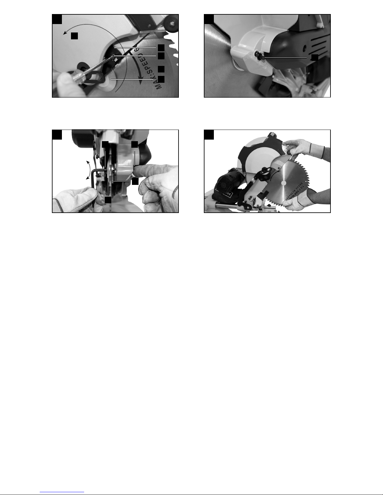
8.8 Schnitttiefenbegrenzung (Abb. 3)
• Mittels der Schraube (26) kann die Schnitttiefe stufen-
los eingestellt werden. Hierzu Rändelmutter an der
Schraube (26) lösen. Den Anschlag für die Schnitttiefenbegrenzung (27) nach außen stellen. Die gewünschte Schnitttiefe durch Eindrehen oder Herausdrehen der Schraube (26) einstellen. Anschließend
die Rändelmutter wieder an der Schraube (26) festziehen.
• Überprüfen Sie die Einstellung anhand eines Probe-
schnittes.
8.9 Spänefangsack (Abb. 2)
Die Säge ist mit einem Spänefangsack (21) für Späne
ausgestattet.
Drücken Sie die Metallringügel des Staubbeutels zusammen und bringen Sie ihn an der Auslaßöffnung im
Motorbereich an.
Der Spänefangsack (21) kann über den Reißverschluss
auf der Unterseite entleert werden.
8.10 Austausch des Sägeblatts (Abb. 15-18)
Netzstecker ziehen!
Achtung!
Tragen Sie zum Wechseln des Sägeblatts Schutzhandschuhe! Verletzungsgefahr!
• Sägeblattschutz (6) öffnen
• Schraube (36) lösen
• Sägeblattschutz (6) nach oben schieben, bis dieser
gehalten wird
• Sägewellensperre (4) fest drücken , und Flansch-
schraube (32) langsam im Uhrzeigersinn drehen.
Nach max. einer Umdrehung rastet die Sägewellensperre (4) ein.
• Jetzt mit etwas mehr Kraftaufwand Flanschschraube
(32) im Uhrzeigersinn lösen.
• Flanschschraube (32) ganz heraus drehen und Au-
ßenansch (33) abnehmen.
• Das Sägeblatt (7) vom Innenansch (37) abnehmen
und nach unten herausziehen.
• Flanschschraube (32), Außenansch (33) und Innen-
ansch (37) sorgfältig reinigen.
• Das neue Sägeblatt (7) in umgekehrter Reihenfolge
wieder einsetzen und festziehen.
• Führungsbügel (38) wieder auf die Schraube (36) set-
zen und sichern.
• Achtung! Die Schnittschräge der Zähne d.h. die Dreh-
richtung des Sägeblattes (7), muss mit der Richtung
des Pfeils auf dem Gehäuse übereinstimmen.
• Vor dem Weiterarbeiten die Funktionsfähigkeit der
Schutzeinrichtungen prüfen.
• Achtung! Nach jedem Sägeblattwechsel prüfen, ob
das Sägeblatt (7) in senkrechter Stellung sowie auf
45° gekippt, frei in der Tischeinlage (11) läuft.
• Achtung! Das Wechseln und Ausrichten des Säge-
blattes (7) muss ordnungsgemäß ausgeführt werden.
Page 16

16
D
8.11 Betrieb Laser (Abb. 2)
• Einschalten: Ein- / Ausschalter Laser (35) in Stellung
„1“ bewegen. Auf das zu bearbeitende Werkstück wird
eine Laserlinie projiziert, die die genaue Schnittführung anzeigt.
• Ausschalten: Ein- / Ausschalter Laser (35) in Stel-
lung „0“ bewegen.
9. Transport (Abb. 1/2)
• Um den Drehtisch (16) zu verriegeln, muß der Fest-
stellgriff (13) angezogen werden.
• Entriegelungshebel (3) betätigen, Maschinenkopf (5)
nach unten drücken und mit Sicherungsbolzen (24)
arretieren. Die Säge ist nun in der unteren Stellung
verriegelt.
• Zugfunktion der Säge mit der Feststellschraube für
Zugführung (23) in der hinteren Position xieren.
• Maschine am Transportgriff (41) tragen.
• Zum erneuten Aufbau der Maschine, wie unter 8.1
beschrieben vorgehen.
10. Wartung
m Warnung! Vor jeglicher Einstellung, Instandhaltung
oder Instandsetzung Netzstecker ziehen!
Allgemeine Wartungsmaßnahmen
Wischen Sie von Zeit zu Zeit mit einem Tuch Späne und
Staub von der Maschine ab. Ölen Sie zur Verlängerung
des Werkzeuglebens einmal pro Monat die Drehteile.
Ölen Sie nicht den Motor.
Benutzen Sie zur Reinigung des Kunststoffes keine ätzenden Mittel.
Bürsteninspektion
Prüfen Sie die 2 Kohlebürsten (42) bei einer neuen Maschine nach den ersten 50 Betriebsstunden, oder wenn
neue Bürsten montiert wurden. Prüfen Sie sie nach der
ersten Prüfung alle 10 Betriebsstunden.
Wenn der Kohlenstoff auf 6 mm Länge abgenutzt ist,
die Feder oder der Nebenschlußdraht verbrannt oder
beschädigt sind, müssen Sie beide Bürsten ersetzen.
Wenn die Bürsten nach dem Ausbau für einsatzfähig
befunden werden, können Sie sie wieder einbauen.
11. Lagerung
Lagern Sie das Gerät und dessen Zubehör an einem
dunklen, trockenen und frostfreiem sowie für Kinder unzugänglichem Ort. Die optimale Lagertemperatur liegt
zwischen 5 und 30˚C.
Bewahren Sie das Elektrowerkzeug in der Originalverpackung auf.
Decken Sie das Elektrowerkzeug ab, um es vor Staub
oder Feuchtigkeit zu schützen.
Bewahren Sie die Bedienungsanleitung bei dem Elektrowerkzeug auf.
12. Elektrischer Anschluss
Der installierte Elektromotor ist betriebsfertig angeschlossen. Der Anschluss entspricht den einschlägigen VDE- und DIN-Bestimmungen. Der kundenseitige Netzanschluss sowie die verwendete
Verlängerungsleitung müssen diesen Vorschriften
entsprechen.
• Das Produkt erfüllt die Anforderungen der EN
61000-3-11 und unterliegt Sonderanschlußbedingungen. Das heisst, dass eine Verwendung an
beliebigen frei wählbaren Anschlusspunkten nicht
zulässig ist.
• Das Gerät kann bei ungünstigen Netzverhältnissen
zu vorübergehenden Spannungsschwankungen
führen.
• Das Produkt ist ausschließlich zur Verwendung an
Anschlußpunkten vorgesehen, die
a) eine maximale zulässige Netzimpedanz “Z”
(Z
max
= 0.382 Ω) nicht überschreiten, oder
b) eine Dauerstrombelastbarkeit des Netzes von
mindestens 100 A je Phase haben.
• Sie müssen als Benutzer sicherstellen, wenn nötig
in Rücksprache mit Ihrem Energieversorgungsunternehmen, daß Ihr Anschlußpunkt, an dem Sie das
Produkt betreiben möchten, eine der beiden genannten Anforderungen a) oder b) erfüllt.
Wichtige Hinweise
Bei Überlastung des Motors schaltet dieser selbständig
ab. Nach einer Abkühlzeit (zeitlich unterschiedlich) lässt
sich der Motor wieder einschalten.
Schadhafte Elektro-Anschlussleitung
An elektrischen Anschlussleitungen entstehen oft Isolationsschäden.
Ursachen hierfür können sein:
• Druckstellen, wenn Anschlussleitungen durch Fenster
oder Türspalten geführt werden.
• Knickstellen durch unsachgemäße Befestigung oder
Führung der Anschlussleitung.
• Schnittstellen durch Überfahren der Anschlusslei-
tung.
• Isolationsschäden durch Herausreißen aus der
Wandsteckdose.
• Risse durch Alterung der Isolation.
Solch schadhafte Elektro-Anschlussleitungen dürfen nicht
verwendet werden und sind aufgrund der Isolationsschäden
lebensgefährlich.
Elektrische Anschlussleitungen regelmäßig auf Schäden überprüfen. Achten Sie darauf, dass beim Überprüfen die Anschlussleitung nicht am Stromnetz hängt.
Elektrische Anschlussleitungen müssen den einschlägigen VDE- und DIN-Bestimmungen entsprechen. Verwenden Sie nur Anschlussleitungen mit Kennzeichnung
H05VV-F.
Ein Aufdruck der Typenbezeichnung auf dem Anschlusskabel ist Vorschrift.
Page 17

17
D
Wechselstrommotor
• Die Netzspannung muss 230 V~ betragen.
• Verlängerungsleitungen bis 25 m Länge müssen ei-
nen Querschnitt von 1,5 Quadratmillimeter aufwei-
sen.
Anschlüsse und Reparaturen der elektrischen Ausrüstung dürfen nur von einer Elektro-Fachkraft durchgeführt werden.
Bei Rückfragen bitte folgende Daten angeben:
• Stromart des Motors
• Daten des Maschinen-Typenschildes
• Daten des Motor-Typschildes
13. Entsorgung und Wiederverwertung
Das Gerät bendet sich in einer Verpackung um Transportschäden zu verhindern. Diese Verpackung ist Rohstoff und ist somit wieder verwendbar oder kann dem
Rohstoffkreislauf zurückgeführt werden.
Das Gerät und dessen Zubehör bestehen aus verschiedenen Materialien, wie z.B. Metall und Kunststoffe. Führen Sie defekte Bauteile der Sondermüllentsorgung zu.
Fragen Sie im Fachgeschäft oder in der Gemeindeverwaltung nach!
14. Störungsabhilfe
Störung Mögliche Ursache Abhilfe
Motor funktioniert nicht Motor, Kabel oder Stecker defekt, Siche-
rungen durchgebrannt
Maschine vom Fachmann überprüfen lassen. Nie
Motor selbst reparieren. Gefahr! Sicherungen kontrollieren, evtl. auswechseln
Der Motor geht langsam an und erreicht die
Betriebsgeschwin-digkeit
nicht.
Spannung zu niedrig, Wicklungen beschädigt, Kondensator durchgebrannt
Spannung durch Elektrizitätswerk kontrollieren
lassen. Motor durch einen Fachmann kontrollieren
lassen. Kondensator durch einen Fachmann auswechseln lassen
Motor macht zu viel Lärm Wicklungen beschädigt, Motor defekt Motor durch einen Fachmann kontrollieren lassen
Motor erreicht volle Leis-
tung nicht.
Stromkreise in Netzanlage überlastet
(Lampen, andere Motoren, etc.)
Verwenden Sie keine andere Geräte oder Motoren
auf demselben Stromkreis
Motor überhitzt sich leicht. Überlastung des Motors, ungenügende
Kühlung des Motors
Überlastung des Motors beim Schneiden verhindern, Staub vom Motor entfernen, damit eine opti-
male Kühlung des Motors gewährleistet ist
Verminderte Schnittleistung
beim Sägen
Sägeblatt zu klein (zu oft geschliffen) Endanschlag des Sägeaggregates neu einstellen
Sägeschnitt ist rau oder
gewellt
Sägeblatt stumpf, Zahnform nicht geeignet für die Materialdicke
Sägeblatt nachschärfen bzw. geeignetes Sägeblatt
einsetzen
Werkstück reißt aus bzw.
splittert
Schnittdruck zu hoch bzw. Sägeblatt für
Einsatz nicht geeignet
Geeignetes Sägeblatt einsetzen
Page 18

18
GB
Table of contents:
Page:
1.
Introduction 20
2.
Device description 20
3.
Scope of delivery 20
4.
Intended use 21
5.
Safety information 21
6.
Technical data 24
7.
Before starting the equipment 24
8.
Attachment and operation 25
9.
Transport 27
10.
Maintenance 27
11.
Storage 27
12.
Electrical connection 27
13.
Disposal and recycling 28
14.
Troubleshooting 28
15.
Declaration of conformity 67
Page 19

19
GB
GB
Caution - Read the operating instructions to reduce the risk of inquiry
GB
Wear safety goggles!
GB
Important! Risk of injury. Never reach into the running saw blade!
0
GB
Important! Laser radiation
GB
Protection class II
GB
Wear ear-muffs!
GB
Wear a breathing mask!
Explanation of the symbols on the equipment
Page 20

20
GB
1. Introduction
MANUFACTURER:
scheppach
Fabrikation von Holzbearbeitungsmaschine GmbH
Günzburger Straße 69
D-89335 Ichenhausen
DEAR CUSTOMER,
We hope your new tool brings you much enjoyment and
success.
NOTE:
According to the applicable product liability laws, the
manufacturer of the device does not assume liability
for damages to the product or damages caused by the
product that occurs due to:
• Improper handling,
• Non-compliance of the operating instructions,
• Repairs by third parties, not by authorized service
technicians,
• Installation and replacement of non-original spare
parts,
• Application other than specied,
• A breakdown of the electrical system that occurs due
to the non-compliance of the electric regulations and
VDE regulations 0100, DIN 57113 / VDE0113.
m Important!
When using electric tools safety precautions should
always be followed to reduce the risk of re, electric
shock and personal injury including the following. Read
all these instructions before attempting to operate this
product and save these instructions. Keep this manual
in a safe place, so that the information is available at
all times. If you give the equipment to any other person,
hand over these operating instructions and safety regulations as well. We cannot accept any liability for damage or accidents which arise due to a failure
In addition to the safety regulations in the operating
instructions, you have to meet the applicable regulations that apply for the operation of the machine in your
country. Keep the operating instructions package with
the machine at all times and store it in a plastic cover
to protect it from dirt and moisture. Read the instruction
manual each time before operating the machine and
carefully follow its information. The machine can only
be operated by persons who were instructed concerning the operation of the machine and who are informed
about the associated dangers. The minimum age requirement must be complied with.
2. Layout (Fig. 1-19)
1. Handle
2. ON/OFF switch
2a. Release for ON/OFF switch
3. Release lever
4. Saw shaft lock
5. Machine head
6. Movable blade guard
7. Saw blade
8. Clamping device
9. Workpiece support
10. Locking screw for workpiece support
11. Table insert
12. Indexed position lever
13. Locking handle
14. Pointer
15. Scale
16. Turntable
17. Fixed saw table
18. Stop rail
19. Scale
20. Pointer
21. Sawdust bag
22. Locking lever
23. Locking screw for drag guide
24. Locking bolt
25. Drag guide
26. Screw for cutting depth limiter
27. Stop for cutting depth limiter
28. Movable stop rail
29. Set screw for moveable stop rail
30. Adjustment screw (90°)
31. Adjustment screw (45°)
32. Flange screw
33. Outer ange
34. Laser
35. ON/OFF switch for laser
36. Screw
37. Inner ange
38. Guide bar
39. Tilt lock
39a. Anti-tilt locking screw
40. Stop plate 90
0
41. Carrying handle
42. Carbon brush (on both sides)
a) 90° stop angle (not supplied)
b) 45° stop angle (not supplied)
c) Allen key, 6 mm
3. Scope of delivery
• Open the packaging and remove the device carefully.
• Remove the packaging material as well as the pack-
aging and transport bracing (if available).
• Check that the delivery is complete.
• Check the device and accessory parts for transport
damage.
• If possible, store the packaging until the warranty pe-
riod has expired.
Page 21

21
GB
ATTENTIO N
The device and packaging materials are not toys!
Children must not be allowed to play with plastic
bags, lm and small parts! There is a risk of swallowing and suffocation!
• Drag, crosscut and mitre Saw
• 1 x Clamping device (8)
• 2 x Workpiece support (9)
• Sawdust bag (21)
• Allen key (c)
• 1x anti-tip
• Operating manual
4. Intended use
The drag, crosscut and mitre saw is designed to crosscut wood and plastic respective of the machine’s size.
The saw is not designed for cutting rewood.
The equipment is to be used only for its prescribed purpose. Any other use is deemed to be a case of misuse.
The user / operator and not the manufacturer will be liable for any damage or injuries of any kind caused as
a result of this.
The equipment is to be operated only with suitable saw
blades. It is prohibited to use any type of cutting-off
wheel.
To use the equipment properly you must also observe
the safety information, the assembly instructions and
the operating instructions to be found in this manual.
All persons who use and service the equipment have to
be acquainted with this manual and must be informed
about the equipment’s potential hazards. It is also imperative to observe the accident prevention regulations
in force in your area. The same applies for the general
rules of health and safety at work.
The manufacturer will not be liable for any changes
made to the equipment nor for any damage resulting
from such changes. Even when the equipment is used
as prescribed it is still impossible to eliminate certain
residual risk factors. The following hazards may arise in
connection with the machine’s construction and
design:
• Contact with the saw blade in the uncovered saw
zone.
• Reaching into the running saw blade (cut injuries).
• Kick-back of workpieces and parts of workpieces.
• Saw blade fracturing.
• Catapulting of faulty carbide tips from the saw blade.
• Damage to hearing if ear-muffs are not used as nec-
essary.
• Harmful emissions of wood dust when used in closed
rooms.
Please note that our equipment has not been designed
for use in commercial, trade or industrial applications.
Our warranty will be voided if the equipment is used in
commercial, trade or industrial businesses or for equivalent purposes.
5. Safety information
Attention! The following basic safety measures must
be observed when using electric tools for protection
against electric shock, and the risk of injury and re.
Read all these notices before using the electric tool and
keep the safety instructions for later reference.
Safe work
1 Keep the work area orderly
– Disorder in the work area can lead to accidents.
2 Take environmental inuences into account
– Do not expose electric tools to rain.
– Do not use electric tools in a damp or wet envi-
ronment.
– Make sure that the work area is well-illuminated.
– Do not use electric tools where there is a risk of
re or explosion.
3 Protect yourself from electric shock
– Avoid physical contact with earthed parts (e.g.
pipes, radiators, electric ranges, cooling units).
4 Keep children away
– Do not allow other persons to touch the equipment
or cable, keep them away from your work area.
5 Securely store unused electric tools
– Unused electric tools should be stored in a dry,
elevated or closed location out of the reach of
children.
6 Do not overload your electric tool
– They work better and more safely in the specied
output range.
7 Use the correct electric tool
– D o not use low-output elect ric tools for heavy work.
– D o not use the electric tool fo r pu rposes for wh ich it
is not intended. For example, do not use handheld
circular saws for the cutting of branches or logs.
– Do not use the electric tool to cut rewood.
8 Wear suitable clothing
– Do not wear wide clothing or jewellery, which can
become entangled in moving parts.
– When working outdoors, anti-slip footwear is rec-
ommended.
– Tie long hair back in a hair net.
9 Use protective equipment
– Wear protective goggles.
– Wear a mask when carrying out dust-creating
work.
10 Connect the dust extraction device if you will
be processing wood, materials similar to wood, or
plastics.
– If connectio ns for dust extraction and a collecting
device are present, make sure that they are connected and used properly.
– When processing wood, materials similar to wood,
and plastics. operation in enclosed spaces is only
permitted wit h the use of a suitab le extracti on sys tem.
11 Do not use the cable for purposes for which it
is not intended
– Do not use the cable to pull the plug out of the outlet.
Protect the cable from heat, oil and sharp edges.
Page 22

22
GB
12 Secure the workpiece
– Use the clamping devices or a vice to hold the
work piece in place. In this manner, it is held mo re
securely than with your hand.
– A n additional support is necessary for long work-
pieces (table, trestle, etc.) in order to prevent the
machine from tipping over.
– Always press the workpiece rmly against the
working plate and stop in order to prevent bouncing and twisting of the workpiece.
13 Avoid abnormal posture
– Make sure that you have secure footing and al-
ways maintain your balance.
– Avoid awkward hand positions in which a sudden
slip could cause one or both hands to come into
contact with the saw blade.
14 Take care of your tools
– Keep cutting tools sharp and clean in order to be
able to work better and more safely.
– Follow the instructions for lubrication and for tool
replacement.
– Check the connection cable of the electric tool
regularly and have it replaced by a recognised
specialist when damaged.
– Check extension cables regularly and replace
them when damaged.
– Keep the handle dry, clean and free of oil and
grease.
15 Pull the plug out of the outlet
– Never remove loose splinters, chips or jammed
wood pieces from the running saw blade.
– D uring non -use of the ele ctric tool or prior to main-
tenance and when replacing tools such as saw
blades, bits, milling heads.
– When the saw blade is blocked due to abnormal
feed force during cutting, turn the machine off
and di sconnect it from power supply. Remove the
work piece and ensure that the saw blade runs
free. Turn the machine on and start new cutting
operation with reduced feed force.
16 Do not leave a tool key inserted
– Before switching on, make sure that keys and ad-
justing tools are removed.
17 Avoid inadvertent starting
– Make sure that the switch is switched off when
plugging the plug into an outlet.
18 Use extension cables for outdoors
– Only use approved and appropriately identied
extension cables for use outdoors.
– Only use cable reels in the unrolled state.
19 Remain attentive
– Pay attention to what you are doing. Remain sen-
sible when working. Do not use the electric tool
when you are distracted.
20 Check the electric tool for potential damage
– Protective devices and other parts must be care-
fully inspected to ensure that they are fault-free
and function as intended prior to continued use
of the electric tool.
– Check whether the moving parts function fault-
lessly and do not jam or whether parts are damaged. All parts must be correctly mounted and all
conditions must be fullled to ensure fault-free
operation of the electric tool.
– The moving protective hood may not be xed in
the open position.
– Damaged protective devices and parts must be
properly repaired or replaced by a recognised
workshop, insofar as nothing different is specied in the operating manual.
– Damaged switches must be replaced at a cus-
tomer service workshop.
– Do not use any faulty or damaged connection
cables.
– Do not use any electric tool on which the switch
cannot be switched on and off.
21 ATTENTION!
– Exercise elevated caution for double mitre cuts.
22 ATTEN TION!
– The use of other insertion tools and other acces-
sories can entail a risk of injury.
23 Have your electric tool repaired by a qualied
electrician
– This electric tool conforms to the applicable safety
regulati ons. Repairs may only be perfo rmed by an
electrician using original spare parts. Otherwise
accidents can occur.
ADDITIONAL SAFETY INSTRUCTIONS
1 Safety precautions
– Warning! Do not use damaged or deformed saw
blades.
– Replace a worn table insert.
– Only use saw blades reco mmended by the manu -
facturer which conform to EN 847-1.
– Make sure that a suitable saw blade for the mate -
rial to be cut is selected.
– Wear suitable personal protective equipment. This
includes:
– Hearing protection to avoid the risk of becom-
ing hearing impaired,
– Respiratory protection to avoid the risk of inhal-
ing harmful dust,
– Wear gloves when handling saw blades and
rough materials. Carry saw blades in a container whenever practical.
– Wear goggles. Sparks generated during work
or splinters, chippings and dust coming from
the device can lead to loss of eyesight.
– Connect a dust collecting device to the electric
tool when sawing wood. The emission of dust is
inuenced, among other things, by the type of
material to be processed, the signicance of local
separation (collection or source) and the correct
setting of the hood/guide plates/guides.
– Do not use saw blades made of high-speed alloy
steel (HSS steel).
Page 23

23
GB
2 Maintenance and repair
– Pull out the mains plug for any adjustment or re-
pair tasks.
– The generation of noise is inuenced by vari-
ous factors, including the characteristics of saw
blades, condition of saw blade and electric tool.
Use saw blades which were designed for reduced
noise development, insofar as possible. Maintain
the electric tool and tool attachments regularly
and if necessary, initiate repairs in order to reduce noise.
– Report faults on the electric tool, protective de-
vices or the tool attachment to the person responsible for safety as soon as they are discovered.
3 Safe work
– Only use saw blades for whic h the maximum per-
missible speed is not lower than the maximum
spindle speed of table saws and which are suitable
for the material to be cut.
– Make sure that the saw blade does not touch the
rota ry tabl e in any position by pulling out the mains
plug and rotating the saw blade by hand in the
45° and 90° position. If necessary, readjust the
saw head.
– When transporting the electric tool, only use the
transport devices. Never use the protective devices for handling or transport.
– Make sure that the lower part of the saw blade is
covered during transport, e.g. by the protective
device.
– Be sure to only use spacers and spindle rings
specied by the manufacturer as suitable for the
intended purpose.
– The oor around the machin e must be level, clean
and free of loose particles, such as chips and
cutting residues.
– Always work from the side to the saw blade.
– Do not remove any cut ting resi dues or other part s
of wor kpieces from the cutting zone while the ma chine is running and the saw unit is not at rest.
– Make sure that the machine is alway s secured on
a workbench or a table if at all possible.
– Support long workpieces (e.g. with a roller table)
to prevent them sagging at the end of a cut.
Warning! This electric tool generates an electromag-
netic eld during operation. This eld can impair active
or passive medical implants under certain conditions. In
order to prevent the risk of serious or deadly injuries, we
recommend that persons with medical implants consult
with their physician and the manufacturer of the medical
implant prior to operating the electric tool.
SAFETY INSTRUCTIONS FOR THE HANDLING OF
SAW BLADES
1 Only use insertion tools if you have mastered their
use.
2 Obser ve the maximum speed. The ma ximum speed
spec ied on the insertion tool may not be exc eeded.
If specied, observe the speed range.
3 Observe the motor / saw blade direction of rotat io n.
4 Do not use any insertion tools with cracks. Sort out
cracked insertion tools. Repairs are not permitted.
5 Clean grease, oil and water off of the clamping sur-
faces.
6 Do not use any loose reducing rings or bushes for
the reducing of holes on saw blades.
7 Make sure that xed reducer rings for securing the
insertion tool have the same diameter and have at
least 1/3 of the cutting diameter.
8 Make sure that xed reducer rings are parallel to
each other.
9 Handle insertion tool with caution. They are ideally
stored in the originally package or special containers. Wear protective gloves in order to improve grip
and to further reduce the risk of injury.
10 Prior to the use of insertion tools, make sure that all
protective devices are properly fastened.
11 Prior to use, make sure that the insertion tool meets
the technical requirements of this electric tool and
is properly fastened.
12 Only use the supplied saw blade for sawing opera-
tions in wood, materials similar to wood, plastics
and non-ferrous metals (except for magnesium and
alloys containing magnesium).
13 Never use the saw to cut other than dened materi-
als.
14 Make sure that the machine is safe before working.
Attention: Laser radiation
Do not stare into the beam
Class 2 laser
Protect yourself and you environment from accidents using suitable precautionary measures!
• Do not look directly into the laser beam with unpro-
tected eyes.
• Never look into the path of the beam.
• Never point the laser beam towards reecting surfac-
es and persons or animals. Even a laser beam with a
low output can cause damage to the eyes.
• Caution - methods other than those specied here
can result in dangerous radiation exposure.
• Never open the laser module. Unexpected exposure
to the beam can occur.
• If the mitre saw is not used for an extended period of
time, the batteries should be removed.
• The laser may not be replaced with a different type
of laser.
• Repairs of the laser may only be carried out by the
laser manufacturer or an authorised representative.
0
Page 24

24
GB
6. Technical data
AC motor 230 V~ 50Hz
Power 2000 Watt
Operating mode S6 2 5%*
Idle speed 4200 min
-1
Carbid e saw blade ø 305 x ø 30 x 3,0 mm
Number of teeth 60
Swivel range -45° / 0°/ +45°
Mitre cut 0° to 45° left / right
Saw width at 90° 340 x 90 mm
Saw width at 45°
240 x 90 mm
Saw width at 2 x 45°
(double mitre cut)
240 x 55 mm
Protection class II
Weight (incl. accessories) 23,0 kg
Laser class 2
Wavelength of laser 650 nm
Laser output < 1 mW
* S6 25%, continuous operation periodic duty.
Identical duty cycles with a period at load followed
by a period at no load. Running time 10 minutes;
duty cycle is 25% of the running time.
The work piece must have a minimum height of
3mm and a minimum width of 10 mm.
Make sure that the workpiece is always secured
with the clamping device.
Noise and vibration
Total vibration values determined in accordance with
EN 61029.
sound pressure level L
pA
99,9 dB(A)
uncertainty K
pA
3 dB
sound power level L
WA
112,9 dB(A)
uncertainty K
WA
3 dB
Wear hearing protection.
The effects of noise can cause a loss of hearing. Total
vibration values (vector sum - three directions) determined in accordance with EN 61029.
Vibration emission value a
h
2,091 m/s²
Uncertainty K 1,5 m/s²
The specied vibration value was established in accordance with a standardized testing method. It may
change according to how the electric equipment is used
and may exceed the specied value in exceptional cir-
cumstances;
The specied vibration value can be used to compare
the equipment with other electric power tools.
The specied vibration value can be used for initial assessment of a harmful effect.
Attention!
The indicated weighted effective value of acceleration
can differ during operation from the indicated value,
dependent on the manner in which the device is used.
Dependent upon the actual conditions of use (periodic
duty) it may be necessary to establish safety precautions for the protection of the operator.
Residual risks
The machine has been built according to the state
of the art and the recognised technical safety requirements.
However, individual residual risks can arise during
operation.
• Health hazard due to electrical power, with the use of
improper electrical connection cables.
• Furthermore, despite all precautions having been
met, some non-obvious residual risks may still remain.
• Residual risks can be minimised if the „safety instructions“ and the „Proper use“ are observed along with
the whole of the operating instructions.
• Do not load the machine unnecessarily: excessive
pressure when sawing will quickly damage the saw
blade, which results in reduced output of the machine
in the processing and in cut precision.
• When cutting plastic material, please always use
clamps: the parts which should be cut must always
be xed between the clamps.
• Avoid accidental starting of the machine: the operating button may not be pressed when inserting the
plug in an outlet.
• Use the tool that is recommended in this manual.
In doing so, your mitre saw provides optimal performance.
• Hands may never enter the processing zone when the
machine is in operation. Release the handle button
and switch off the machine prior to any operations.
7. Before starting the equipment
• The equipment must be set up where it can stand
securely, i.e. it should be bolted to a workbench, a
universal base frame or similar.
• All covers and safety devices have to be properly tted before the equipment is switched on.
• It must be possible for the blade to run freely.
• When working with wood that has been processed
before, watch out for foreign bodies such as nails or
screws, etc.
• Before you press the ON/OFF switch check that the
saw blade is tted correctly. Moving parts must run
smoothly.
• Before you connect the equipment to the power supply make sure the data on the rating plate are identical to the mains data.
Page 25

25
GB
8. Attachment and operation
8.1 Attaching the saw (Fig. 1/2/6a-c)
• To adjust the turntable (16) turn the locking handle
(13) clockwise to release the lock.
• Slide the locking position lever (12) upwards. To do
this, take your index nger.
• Now adjust the turntable (16) and pointer (14) by use-
ing the required angle of the scale (15). Fix it by turning the locking handle (13) counterclockwise.
• Pressing the machine head (5) lightly downwards and
removing the locking bolt (24) from the motor bracket
at the same time disengages the saw from the lowest position.
• Swing the machine head (5) up until the release lever
(3) latches into place.
• It is possible to secure the clamping device (8) to the
left or right on the stationary saw bench (17).
• Attach the workpiece supports (9) to the xed saw
table (17) as shown in Figure 6a,b,c and push all the
way through. Secure the shafts with the screws to
prevent them from slipping out accidentally. Then fasten in the desired position with the screw (10).
• Install anti-tilt (42) on the xed saw table (17) and
push it completely. (See Fig. 6c) Secure the shaft with
a screw (42a) against loosening.
• The machine head (5) can be tilt left or right to max.
450 by opening the locking handle (22).
8.2 Precision adjustment of the stop for crosscut
90° (Fig. 1/2/5/7/8)
• No stop angle (a) included.
• Lower the machine head (5) and secure using the
locking bolt (24).
• Loosen the locking lever (22).
• Position the angle stop (a) between the saw blade (7)
and the rotary table (16).
• Flip stop plate 900 (40) at top
• Slacken the counternut (Fig. 8 Pos. d). Adjust the ad-
justing screw (30) until the angle between the saw
blade (7) and rotary table (16) is 90°.
• Retighten the counternut (d) to secure this setting.
• Subsequently check the position of the angle indi-
cator. If necessary loosen the pointer (20) using a
Philips screwdriver, set to position 0° on the angle
scale (19) and re-tighten the retaining screw.
8.3 Precision adjustment of the stop for mitre cut +45°/-
45° (Fig. 1/2/5/9/10)
• No stop angle (b) included.
• Lower the machine head (5) and secure using the
locking bolt (24).
• Fix the rotary table (16) in the 0° position.
• Loosen the locking lever (22) and use the handle (1)
to angle the machine head (5) 45° to the left or right.
• 45° - position angle stop (b) between the saw blade
(7) and rotary table (16).
• Slacken the counternut (c). Adjust the adjusting screw
(31) until the angle between the saw blade (7) and rotary table (16) is precisely +45°/-45°.
• Retighten the counternut (c) to secure this setting.
8.4 Cross cut 90° and turntable 0° (Fig.1/2/11/12)
In the case of cutting widths up to approx. 100 mm it is
possible to x the traction function of the saw with the
set screw (23) in the rear position. In this position the
machine can be operated in cross cutting mode. If the
cutting width is over 100 mm then it is necessary to ensure that the set screw (23) is loose and the machine
head (5) can move.
Attention! For 90° mitre cuts, the moveable stop
rail (28) must be xed in the inner position on both
sides. (see Fig. 11)
• Open the set screw (29) on the moveable stop rail
(28) and push the moveable stop rail (28) inwards.
• The moveable stop rail (28) must be locked in a posi-
tion far enough from the inner position that the distance between the stop rail (28) and the saw blade
(7) is no more than 8 mm. (see Fig. 12)
• Before making the cut, check that no collision could
occur between the stop rail (28) and the saw blade
(7).
• Tighten the set screw (29) again.
• Move the machine head (5) to its upper position.
• Use the handle (1) to push back the machine head
(5) and x it in this position if required (dependent on
the cutting width).
• Place the piece of wood to be cut at the stop rail (18)
and on the turntable (16).
• Lock the material with the clamping device (8) on the
xed saw table (16) to prevent the material from moving during the cutting operation.
• Push down the release lever (3) to release the ma-
chine head (5).
• Press the ON/OFF switch (2) and the unlocking
switch (2a) to start the motor.
• With the drag guide (23) xed in place:
use the handle (1) to move the machine head (5)
steadily and with light pressure downwards until the
saw blade (7) has completely cut through the work
piece.
• With the drag guide (23) not xed in place:
pull the machine head (5) all the way to the front.
Lower the handle (1) to the very bottom by applying
steady and light downward pressure. Now push the
machine head (5) slowly and steadily to the very back
until the saw blade (7) has completely cut through
the work piece.
• When the cutting operation is completed, move
the machine head (5) back to its upper (home)
position and release the ON/OFF button (2).
Attention! The machine executes an upward stroke
automatically due to the return spring, i.e. do not release the handle (1) af ter completing the cut; instead
allow the machine head to move upwards slowly
whilst applying light counter pressure.
8.5 Cross cut 90° and turntable 0°- 45° (Fig.
1/2/11/12)
The crosscut saw can be used to make crosscuts of
0°-45° to the left and 0°-45° to the right in relation to
the stop rail.
Page 26

26
GB
Attention! For bevel cuts (inclined saw head), the
moveable stop rail (28) must be xed in the outer
position on both sides. (see Fig. 11)
• Open the set screw (29) on the moveable stop rail
(28) and push the moveable stop rail (28) outwards.
• The moveable stop rail (28) must be locked in a posi-
tion far enough from the inner position that the distance between the stop rail (28) and the saw blade
(7) is no more than 8 mm. (see Fig. 12)
• Before making the cut, check that no collision could
occur between the stop rail (28) and the saw blade (7).
• Tighten the set screw (29) again.
• Loosen the locking handle (13) counterclockwise and
pull the indexed position lever (12) with the index nger at top.
• Set the turntable (16) to the desired angle by using
the locking handle (13). The pointer (14) on the turntable (16) must match with the desired angular scale
(15) on the xed saw table (17).
• Turn the locking handle (13) clock wise to x the turn-
table (16).
• Cut as described under section 8.4.
8.6 Mitre cut 0°- 45° and turntable 0° (Fig. 1/2/11-14)
The crosscut saw can be used to make mitre cuts of 0°
- 45° to left/right in relation to the work face.
Important. To make miter cuts (inclined saw head),
the adjustable stop rail (28a/28b) must be xed at
the outer position.
• Open the locking screw (29) for the adjustable stop
rail (28) and push the adjustable stop rail (of inclined
side) outwards. (see Fig. 13+14)
• The other adjustable stop rail (28) must be xed far
enough in front of the innermost position that the distance between the stop rail (28) and the saw blade (7)
amounts to a maximum of 8 mm. (see Fig. 12)
• Before making a cut, check that the stop rail (28) and
the saw blade (7) cannot collide.
• Secure the locking screw (29) again.
• Move the machine head (5) to the top position.
• Fix the rotary table (16) in the 0° position.
• Loosen the locking lever (22) and use the handle (1)
to angle the machine head (5) to the left/right, until
the pointer (20) indicates the desired angle measurement on the scale (19).
• Re-tighten the locking lever (22).
• Cut as described in section 8.4.
8.7 Mitre cut 0°- 45° and turntable 0°- 45°
(Fig. 1-2/11-14)
The crosscut saw can be used to make mitre cuts to the
left/right of 0°- 45° in relation to the work face and, at
the same time, 0°- 45° to the left or 0°- 45° to the right
in relation to the stop rail (double mitre cut).
Important. To make miter cuts (inclined saw head),
the adjustable stop rail (28) must be xed at the
outer position.
• Open the locking screw (29) for the adjustable stop
rail (28a/28b) and push the adjustable stop rail (of inclined side) outwards. (see Fig. 13+14)
• The other adjustable stop rail (28) must be xed far
enough in front of the innermost position that the distance between the stop rail (28) and the saw blade (7)
amounts to a maximum of 8 mm. (see Fig. 12)
• Before making a cut, check that the stop rail (28) and
the saw blade (7) cannot collide.
• Secure the locking screw (29) again.
• Move the machine head (5) to its upper position.
• Loosen the locking handle (13) counterclockwise and
pull the indexed position lever (12) with the index nger at top.
• Set the turntable (16) to the desired angle by using
the locking handle (13). The pointer (14) on the turntable (16) must match with the desired angular scale
(15) on the xed saw table (17).
• Turn the locking handle (13) clock wise to x the turn-
table (16).
• Loosening the locking lever (22).
• Use the handle (1) to angle the machine head (5) to
the left/right, until the pointer (20) indicates the desired angle measurement on the scale (19). (in this
connection see also section 8.6).
• Re-tighten the locking lever (22).
• Cut as described under section 8.4.
8.8 Limiting the cutting depth (Fig. 3)
• The cutting depth can be innitely adjusted using the
screw (26). To do this loosen the knurled nut on the
screw (26). Move the stop for the cutting depth limitre (27) to the outside. Turn the screw (26) in or out
to set the required cutting depth. Then re-tighten the
knurled nut on the screw (26).
• Check the setting by completing a test cut.
8.9 Sawdust bag (Fig. 2)
The saw is equipped with a debris bag (21) for sawdust
and chips.
Squeeze together the metal ring on the dust bag and
attach it to the outlet opening in the motor area.
The debris bag (21) can be emptied by means of a zipper at the bottom.
8.10 Changing the saw blade (Fig. 15-18)
Remove the power plug!
Important.
Wear safety gloves when changing the saw blade.
Risk of injury!
• Blade guard (6) open
• Loosen the screw (36)
• Blade guard (6) upwards until it is held
• Firmly press the saw shaft lock (4), and slowly turn
the ange screw (32) clockwise. After max. one turn,
the saw shaft lock (4) engages.
• Then undo the ange screw (32), by applying a slight-
ly greater force in a clockwise direction.
• Fully unscrew the ange screw (32) and remove the
outer ange (33).
• Then remove the saw blade (7) from the inner ange
(39) and pull out in a downwards direction.
• Carefully clean the ange screw (32), outer ange
(33) and inner ange (39).
Page 27

27
GB
• Insert the new saw blade (7) in the reverse sequence
and tighten.
• Position the guide bar (40) on the pin (36) again, and
secure.
• Important! The cutting angle of the teeth, in other
words the direction of rotation of the saw blade (7)
must coincide with the direction of the arrow on the
housing.
• Before continuing your work make sure that all safety
devices are in good working condition.
• Important! Every time that you change the saw blade
(7), check to see that it spins freely in the table insert
(11) in both perpendicular and 45° angle settings.
• Important! The work to change and align the saw
blade (7) must be carried out correctly.
8.11 Using the laser (Fig. 2)
• To switch on: Move the ON/OFF switch of the laser
(35) to the “I” position. A laser line is projected onto
the material you wish to process, providing an exact
guide for the cut.
• To switch off: Move the ON/OFF switch of the laser
(35) to the “0” position.
9. Transport (Fig. 1/2)
• Tighten the locking handle (13) in order to lock the
rotary table (16)
• Activate the release lever (3), press the machine head
(5) downwards and secure with the safety pin (24).
The saw is now locked in its bottom position.
• Fix the saw’s drag function with the locking screw for
drag guide (23) in rear position.
• Wearing the machine at the transport handle (44).
• When reassembling the equipment proceed as de-
scribed under section 8.1.
10. Maintenance
m Warning! Prior to any adjustment, maintenance or
service work disconnect the mains power plug!
General maintenance measures
Wipe chips and dust off the machine from time to time
using a cloth. In order to extend the service life of the
tool, oil the rotary parts once monthly. Do not oil the
motor.
When cleaning the plastic do not use corrosive products.
Brush inspection
Check the 2 carbon brushes (42) after the rst 50 operating hours with a new machine, or when new brushes
have been tted. After carrying out the rst check, repeat the check every 10 operating hours.
If the carbon is worn to a length of 6 mm, or if the spring
or contact wire are burned or damaged, it is necessary
to replace both brushes. If the brushes are found to be
usable following removal, it is possible to reinstall them.
11. Storage
Store the device and its accessories in a dark, dry and
frost-proof place that is inaccessible to children. The
optimum storage temperature is between 5 and 30˚C.
Store the electrical tool in its original packaging.
Cover the electrical tool in order to protect it from dust
and moisture.
Store the operating manual with the electrical tool.
12. Electrical connection
The electrical motor installed is connected and
ready for operation. The connection complies with
the applicable VDE and DIN provisions.
The customer‘s mains connection as well as the
extension cable used must also comply with these
regulations.
• The product meets the requirements of
EN 61000-3-11 and is subject to special connection conditions. This means that use of the product
at any freely selectable connection point is not allowed.
• Given unfavorable conditions in the power supply the
product can cause the voltage to uctuate temporarily.
• The product is exclusively intended for use at con-
nection points that have a continuous current-carrying capacity of at least 100 A per phase.
• As the user, you are required to ensure, in consulta-
tion with your electric power company if necessary,
that the connection point at which you wish to operate the product meets the specied requirements.
Important information
In the event of an overloading the motor will switch itself
off. After a cool-down period (time varies) the motor can
be switched back on again.
Damaged electrical connection cable
The insulation on electrical connection cables is often
damaged.
This may have the following causes:
• Passage points, where connection cables are passed
through windows or doors.
• Kinks where the connection cable has been improp-
erly fastened or routed.
• Places where the connection cables have been cut
due to being driven over.
• Insulation damage due to being ripped out of the wall
outlet.
• Cracks due to the insulation ageing.
Such damaged electrical connection cables must not
be used and are life-threatening due to the insulation
damage.
Check the electrical connection cables for damage regularly. Make sure that the connection cable does not
hang on the power network during the inspection.
Electrical connection cables must comply with the applicable VDE and DIN provisions. Only use connection
cables with the marking „H05VV-F“.
Page 28

28
GB
14. Troubleshooting
Fault Possible cause Remedy
Motor does not work Motor, cable or plug defective, fuses burnt Arrange for inspection of the machine by a special-
ist. Never repair the motor yourself. Danger! Check
fuses and replace as necessary
The motor starts up
slowly and does not
reach operating speed.
Voltage too low, coils damaged, capacitor
burnt
Contact the utility provider to check the voltage.
Arrange for inspection of the motor by a specialist. Arrange for replacement of the capacitor by a
specialist
Motor makes excessive
noise
Coils damaged, motor defective Arrange for inspection of the motor by a specialist
The motor does not
reach its full power.
Circuits in the network are overloaded (lamps,
other motors, etc.)
Do not use any other equipment or motors on the
same circuit
Motor overheats easily. Overloading of the motor, insufcient cooling
of the motor
Avoid overloading the motor while cutting, remove
dust from the motor in order to ensure optimal cool-
ing of the motor
Reduced cutting power
when sawing
Saw blade too small (ground too much) Readjust end stop of the saw unit
Saw cut is rough or
wavy
Saw blade dull, tooth shape not appropriate
for the material thickness
Resharpen saw blade and/or use suitable saw
blade
Workpiece pulls away
and/or splinters
Excessive cutting pressure and/or saw blade
not suitable for use
Insert suitable saw blade
The printing of the type designation on the connection
cable is mandatory.
AC motor
• The mains voltage must be 230 V~
• Extension cables up to 25 m long must have a cross-
section of 1.5 mm2.
Connections and repairs of electrical equipment
may only be carried out by an electrician.
Please provide the following information in the event
of any enquiries:
• Type of current for the motor
• Machine data - type plate
• Machine data - type plate
13. Disposal and recycling
The equipment is supplied in packaging to prevent it
from being damaged in transit. The raw materials in this
packaging can be reused or recycled. The equipment
and its accessories are made of various types of material, such as metal and plastic. Defective components
must be disposed of as special waste. Ask your dealer
or your local council.
Page 29

29
FR
Table des matières:
Page:
1.
Introduction 31
2.
Description de l'appareil 31
3.
Ensemble de livraison 31
4.
Utilisation conforme 32
5.
Notes importantes 32
6.
Caractéristiques techniques 35
7.
Avant la mise en service 36
8.
Structure et commande 36
9.
Transport 39
10.
Maintenance 39
11.
Stockage 39
12.
Raccordement électrique 39
13.
Mise au rebut et recyclage 40
14.
Dépannage 40
15.
Déclaration de conformité 67
Page 30

30
FR
FR
AVERTISSEMENT - pour réduire le risque de blessure, lisez le mode d’emploi!
FR
Portez des lunettes de protection!
FR
Attention! Risque de blessure! Ne mettez pas vos doigts sur la lame en rotation!
FR
Attention! Rayonnement Laser
FR
Catégorie de protection II
FR
Portez une protection auditive!
FR
Portez un masque anti-poussière!
Légende des symboles gurant sur l’appareil
Page 31

31
FR
1. Introduction
FABRICANT :
scheppach
Fabrikation von Holzbearbeitungsmaschine GmbH
Günzburger Straße 69
D-89335 Ichenhausen
CHER CLIENT,
Nous espérons que votre nouvelle machine vous apportera de la satisfaction et de bons résultats.
REMARQUE:
Selon la loi en vigueur sur la responsabilité du fait des
produits, le fabricant n’est pas tenu pour responsable de
tous les dommages subis par cet appareil et pour tous
les dommages résultant de son utilisation, dans les cas
suivants :
• Mauvaise manipulation,
• Non-respect des instructions d‘utilisation,
• Travaux de réparation effectués par des tiers, par des
spécialistes non agréés,
• Remplacement et montage de pièces de rechange
qui ne sont pas d‘origine.
• Utilisation non conforme,
• Lors d’une défaillance du système électrique en cas
de non-respect des réglementations électriques et
des normes VDE 0100, DIN 57113 / VDE0113.
m Attention !
Lors de lʼutilisation dʼappareils, il faut respecter certaines mesures de sécurité an dʼéviter des blessures
et dommages. Veuillez donc lire attentivement ce mode
dʼemploi/ces consignes de sécurité. Veillez à le conserver en bon état pour pouvoir accéder aux informations à
tout moment. Si lʼappareil doit être remis à dʼautres personnes, veillez à leur remettre aussi ce mode dʼemploi/
ces consignes de sécurité. Nous déclinons toute responsabilité pour les accidents et dommages dus au
non-respect de ce mode dʼemploi et des consignes de
sécurité.
En plus des consignes de sécurité continues dans ce
manuel d‘utilisation, vous devez respecter scrupuleusement les réglementations et les lois applicables lors de
l‘utilisation de la machine dans votre pays.
Conservez le manuel d‘utilisation dans une pochette
plastique pour le protéger de la saleté et de l‘humidité,
auprès de la machine. Avant de commencer à travailler avec la machine, chaque utilisateur doit lire le manuel d‘utilisation puis le suivre attentivement. Seules
les personnes formées à l‘utilisation de la machine et
conscientes des risques associés sont autorisées à travailler avec la machine. L‘âge minimum requis doit être
respecté.
2. Description de l’appareil (Fig. 1-19)
1. Poignée
2. Interrupteur Marche / Arrêt
2a. Interrupteur de déverrouillage Marche/Arrêt
3. Levier de déverrouillage
4. Blocage de l’arbre de scie
5. Tête de la machine
6. Capot de protection de lame de scie mobile
7. Lame de scie
8. Dispositif de maintien des pièces à scier
9. Support latéral extensible
10. Vis de xation du support latéral
11. Insert de table
12. Poignée de verrouillage de position
13. Levier de blocage
14. Pointeur
15. Graduation
16. Table orientable
17. Table xe
18. Butée
19. Graduation
20. Pointeur
21. Sac collecteur de copeaux
22. Manette de blocage
23. Vis de xation du guidage radial
24. Boulon de securité
25. Guidage radial
26. Vis moletée de limitation de la profondeur de coupe
27. Butée de limitation de la profondeur de coupe
28. Rai de butée mobile
29. Vis de blocage de la butée mobile
30. Vis d’ajustage (90°)
31. Vis d’ajustage (45°)
32. Vis de bride
33. Bride extérieure
34. Laser
35. Interrupteur Marche / Arrêt du laser
36. Vis
37. Flasque intérieur
38. Etrier de guidage
39. Sécurité anti-basculement
39a. Vis de xation de la sécurité anti-basculement
40. Butée à 90°
41. Poignée de transport
42. Charbons (des deux côtés)
a) Equerre à 90° (non comprise dans la livraison)
b) Equerre à 45° (non comprise dans la livraison)
c) Clé allen, 6 mm
3. Ensemble de livraison
• Ouvrez l’emballage et sortez-en délicatement l’appa-
reil.
• Retirez les matériaux d’emballage, ainsi que les pro-
tections mise en place pour le transpor t (s’il y a lieu).
• Vériez que les fournitures sont complètes.
• Vériez que l’appareil et les accessoires n’ont pas été
endommagés lors du transport.
Page 32

32
FR
• Conservez si possible l’emballage jusqu’à la n de la
période de garantie.
ATTENTIO N
L’appareil et les matériaux d’emballage ne sont pas
des jouets ! Les enfants ne doivent en aucun cas
jouer avec les sacs en plastique, lms d’emballage
et pièces de petite taille ! Il existe un risque d’ingestion et d’asphyxie !
• Scie à onglet radiale
• Dispositifs tendeurs (8)
• 2 x supports de pièces (9)
• Sac collecteur de copeaux (21)
• Clé allen (c)
• 1x anti-basculement
• Mode d’emploi
4. Utilisation conforme
La scie passe-partout, tronçonneuse et de coupe d’onglet sert à tronçonner le bois et les matières plastiques
en fonction des dimensions de la machine. La scie ne
convient pas pour couper du bois de chauffage.
La scie ne convient pas à la découpe du bois de chauffage.
La machine doit être utilisée selon les indications fournies.
Seules des lames de scie correspondant à la machine peuvent être utilisées. Il est interdit d‘utiliser des
disques à tronçonner.
L’utilisation conforme consiste à respecter les consignes
de sécurité, ainsi que les instructions de montage et les
consignes d‘utilisation du mode d‘emploi.
Les personnes utilisant la machine et en assurant
la maintenance doivent bien la connaître, ainsi que
connaître les dangers possibles qu‘elle implique.
Toute autre utilisation est considérée comme étant
non conforme. Le fabricant décline toute responsabilité quant aux dommages ou blessures qui en résulteraient. Dans ce cas, l‘utilisateur/opérateur est le seul
responsable.
En outre, les prescriptions de prévention des accidents
doivent être respectées de la manière la plus scrupuleuse possible.
Toutes les autres règles de médecine du travail et de
sécurité doivent être respectées.
Toute modication de la machine annule toute garantie
du fabricant pour les dommages en résultant.
Une utilisation conforme ne permet pas d‘exclure totalement certains facteurs de risque résiduels. De par la
construction et la structure de la machine, les événements suivants peuvent se produire :
• Contact avec la lame de scie dans la zone de sciage
non protégée.
• Contact avec la lame de scie en cours de fonctionnement (blessure par coupure).
• Mouvement de recul des pièces et des chutes.
• Cassure de la lame de scie.
• Projection de pièces de métal dur de la lame de scie,
présentant un défaut.
• Dommages au niveau de l‘audition en cas de négli-
gence quant au port de la protection auditive nécessaire.
• Émissions de sciure de bois nocive pour la santé en
cas d‘utilisation en espaces clos.
Remarque : conformément aux dispositions, nos appareils n‘ont pas été conçus pour une utilisation commerciale, artisanale ou industrielle. Nous déclinons toute
responsabilité si l‘appareil est utilisé dans des exploitations commerciales, artisanales ou industrielles, ou
dans le cadre d‘activités comparables.
5. Notes importantes
Attention ! Les consignes de sécurité suivantes
doivent impérativement être respectées lors de l’utilisation d’outils électriques pour éviter les électrocutions,
les risques de blessures et d’incendie. Lisez toutes les
instructions avant d’utiliser l’outil électrique et conservez les consignes de sécurité.
Travail en toute sécurité
1 Maintenir l‘ordre dans la zone de travail
– Le désordre régnant dans la zone de travail peut
entraîner des accidents.
2 Prendre en compte les facteurs environnementaux
– Ne pas exposer les outils électriques à la pluie.
– Ne pas utiliser les outils électriques dans un envi-
ronnement humide ou mouillé.
– Veiller à ce qu e la zone de travail soit bie n éclairée.
– Ne pas utiliser les outils électriques dans les lieux
soumis à des risques d‘incendie ou d‘explosion.
3 Assurer une protection contre les chocs élec-
triques
– Éviter tout contact du corps avec les pièces mises
à la terre (par exemple, tuyaux, radiateurs, fours
électriques, appareils de réfrigération).
4 Tenez les enfants à l‘écart !
– Ne laissez pas d’autres personnes toucher l’outil
ou le câble, éloignez-les de votre poste de travail.
5 Conserver les outils électriques non utilisés en
sécurité
– Les outils électriques non utilisés doivent être
conservés dans un lieu sec, en hauteur ou fermé,
hors de portée des enfants.
6 Ne pas forcer l‘outil électrique
– Il fonctionne en effet de manière plus satisfaisante
et plus sûre dans sa plage de performances.
7 Utiliser le bon outil électrique
– Ne pas utiliser d‘outils électriques de faibles per-
formances pour réaliser des travaux exigeants.
– Ne pas utiliser l‘outil électrique à des ns pour
lesquelles il n‘a pas été prévu. Par exemple, ne pas
utiliser de scie circulaire manuelle pour découper
des poteaux de construction ou des bûches de
bois.
8 Porter des vêtements adaptés
– Ne pas porter de vêtements amples ou de bijoux
qui risqueraient d‘être entraînés par les pièces
mobiles.
Page 33

33
FR
– En cas de travail en extérieur, il est recommandé
de porter des chaussures antidérapantes.
– Recouvrir les cheveux longs d‘un let.
9 Utiliser des équipements de protection
– Porter des lunettes de protection.
– Si l‘intervention génère de la poussière, porter un
masque respiratoire.
10 Raccordez un dispositif d’aspiration des pous-
sières si vous êtes amené à usiner du bois, des
matériaux semblables au bois ou des matières
plastiques.
– Si des raccords sont disponibles pour l’aspiration
et la collecte des poussières, veillez à ce qu’ils
soient raccordés et utilisés correctement.
– Une utilisation en espace clos n’est permise
qu’avec une installation d’aspiration adaptée lors
de l’usinage du bois, des matériaux semblables
au bois et des matières plastiques.
11 Ne pas utiliser le câble d’alimentation dans de
mauvaises conditions
– Ne pas tirer sur le câble pour débrancher la che
de la prise. Protéger le câble de la chaleur, de
l‘huile et des arêtes coupantes.
12 Fixation de la pièce à usiner
– Utiliser des dispositifs de serrage ou un étau pour
maintenir la pièce. Elle sera ainsi maintenue de
manière plus sûre qu‘à la main.
– En présence de pi èc es longues, il est nécessaire
d‘utiliser un support supplémentaire (table, tréteaux, etc.) an d‘éviter que la machine ne bascule.
– Appuyer toujours fermement la pièce contre le
plateau de travail et la butée pour éviter que la
pièce ne bouge ou ne se torde.
13 Éviter les positions du corps anormales
– Veiller à adopter une position stable et à toujours
maintenir son équilibre.
– Éviter le s positions maladroites des mains qui ris-
queraient de toucher la lame de la scie en cas de
glissement soudain.
14 Prendre soin de ses outils
– Veiller à ce que les outils de découpe demeurent
affûtés et propres an d‘assurer un fonctionnement plus efcace et plus sûr.
– Respecter les consignes de graissage et de rem-
placement des outils.
– Contrôler régulièrement le câble de raccordement
de l‘outil électrique et le faire remplacer par un
spécialiste agréé en cas de dommage.
– Contrôler régulièrement les rallonges et les rem-
placer en cas de dommage.
– Veiller à ce que les poignées soient sèches,
propres et exemptes d‘huile et de graisse.
15 Toujours débrancher la machine
– Ne pas retirer de chutes, de copeaux ou de pièces
coincées pendant que la lame tourne.
– En cas de non-utilisation de l‘outil électrique,
avant une opération de maintenance et lors du
remplacement des outils, par exemple, lame de
scie, foret, fraise.
– Lorsque la lame de scie se bloque en raison
d’une pression anormale ou trop forte exercée par l’utilisateur lors de la coupe, éteignez la machine et débranchez-la du secteur.
Retirez la pièce en cours de sciage et veillez
à ce que la lame de scie tourne librement une
fois dégagée. Mettez la machine en marche et
recommencez la coupe en exerçant une pression
réduite.
16 Retirer les clés de réglages
– Avant toute mise en service, veiller à ce que les
clés et outils de réglages aient été retirés.
17 Éviter une mise en marche involontaire
– S‘assurer lors du branchement de la che dans la
prise que l‘interrupteur est éteint.
18 Utiliser la rallonge pour l‘extérieur
– En extérieur, utiliser uniquement des rallonges
conformes et marquées comme étant conformes
à cet emploi.
– N‘utiliser les tambours de câbles que lorsqu‘ils
sont déroulés.
19 Rester vigilant
– Regarder ce que vous êtes en train de faire, faire
preuve de bon sens et ne pas utiliser l’outil lorsque
vous êtes fatigué.
– Ne pas utiliser l’outil si l’interrupteur ne permet
pas de passer de l’état de marche à l’état d’arrêt.
20 Vérier si l‘outil électrique présente des dom-
mages
– Avant de poursuivre l‘utilisation de l‘outil élec-
trique, il convient de vérier soigneusement que
les dispositifs de protection et les autres pièces
fonctionnent parfaitement et conformément aux
dispositions.
– Vérier que les pièces mobiles fonctionnent par-
faitement, ne sont pas coincées et ne sont pas
endommagées. Toutes les pièces doivent être
montées correctement et toutes les conditions
doivent être remplies pour garantir un fonctionnement impeccable de l‘outil électrique.
– Le capot de protection ne doit pas être bloqué en
position ouverte.
– Sauf indication contraire dans la notice d‘utilisa-
tion, les dispositifs de protection et pièces endommagés doivent être réparés ou remplacés conformément aux dispositions par un atelier spécialisé
et agréé.
– Les interrupteurs défectueux (ex : ne permettant
pas de passer de l’état de marche à l’état d’arrêt)
doivent être remplacés par un atelier de service
après-vente.
– Ne pas utiliser de câbles de raccordement défail-
lants ou endommagés.
– Ne pas utiliser d‘outils électriques pour lesquels
les ches ne se branchent et ne se débranchent
pas.
21 ATTENTION !
– Les doubles découpes de biais réclament une
attention particulière.
Page 34

34
FR
22 ATTEN TION !
– L’utilisation de tout accessoire ou de toute xation
autre que celui ou celle recommandé(e) dans le
présent manuel d’instructions peut présenter un
risque de blessure des personnes.
23 Faire réparer l‘outil électrique par un électricien
spécialisé
– Cet outil électrique est conforme aux dispositions
de séc urité en vigueu r. Les réparations ne doivent
être menée à bien que par un électricien spécialisé qui utilisera des pièc es de rechang e d‘origine.
Sinon, l‘utilisateur risque l‘accident.
CONSIGNES DE SÉCURITÉ
SUPPLÉMENTAIRES
1 Mesures de prévention
– Avertissement ! Ne pas utiliser de lames de scie
endommagées ou déformées.
– Remplacer le bloc de table dès qu‘il est usé.
– Utiliser uniquement des lames de scie recomman-
dées par le fabricant et conformes à la norme
EN 847-1.
– Veiller à choisir une lame de scie correspondant
au matériau à découper.
– Porter un équipement de protection individuelle
adapté. Cet équipement comprend :
– Protection auditive visant à réduire le risque
de dommage pour l‘ouïe.
– Protection respiratoire visant à réduire le risque
lié aux poussières nocives.
– Porter des gants lors de la manipulation des
lames de scie et des matériaux rugueux. Dans
la mesure du possible, transporter les lames
de scie dans un support.
– Portez des lunettes de protection. Les étin-
celles générées pendant le travail, de même
que le s éclats, copeaux et poussiè re s s‘écha ppant de l‘appareil peuvent faire perdre la vue.
– Raccorder l‘appareil électrique à un dispositif de
co llecte des po us sières lors du sciage de bois. La
poussière générée dépend entre autres du type
de matériau à traiter, de l‘efcacité du dispositif
de séparation en place (captage ou source) et du
réglage correct des capots/déecteurs/guidages.
– Ne pas utiliser de lames de scie en acier rapide
à fort alliage (acier HSS).
2 Maintenance et entretien
– Débrancher le connecteur secteur pour toute
intervention de réglage et de maintenance.
– Le bruit émis dépend de divers facteurs, notam-
ment du type de lame de scie, de son état et de
l‘outil électrique. Utiliser dans la mesure du possible des lames de scie conçues pour réduire
l’émission de bruit. Procéder régulièrement à la
maintenance de l‘outil électrique et de ses accessoires an de réduire le niveau sonore.
– Signaler à la personne en charge de la sécurité les
défauts de l‘outil électrique, les dispo sitifs de protection ou les accessoires dès qu‘ils sont décelés.
3 Travail en toute sécurité
– Utiliser uniquement des lames de scie dont la
vitesse maximale autorisée n‘est pas inférieure
à la vitesse maximale de la scie circulaire. Elles
devront en outre être adaptées au matériau à
découper.
– Veiller à ce que la lame de sc ie ne touch e absolu-
ment pas la table orientable en amenant manuellement (câble secteur débranché) la lame à 45°
et à 90°. Ajuster au besoin la tête de la scie en
procédant comme indiqué au point 8.3/8.4.
– Lo rs du transpor t de l‘outil électrique, utiliser uni-
quement les dispositifs de transport. N‘utiliser
jamais les dispositifs de protection pour la manipulation ou le transport.
– Pendant le transport, veiller à ce que la partie
inférieure de la lame de scie soit recouverte, par
exemple, par le dispositif de protection.
– Veillez à n’utiliser que des disques , des cales
et des bagues de serrage de l’arbre considérées
par le fabricant comme appropriées et adaptées
à l’alésage de la lame.
– Le sol autour de la machine doit être plat, propre
et net de déch et s (par exemp le: copeaux et chutes
de coupe).
– Tenez vous toujours de côté par rapport à lame
de scie.
– Ne retirez pas de chutes de coupes ni d’autres
morceaux détachés de la pièce à usiner dans
la zone de coupe pendant que la machine fonctionne, que la lame de scie ne s’est pas complètement arrêtée et tant que la tête de scie n’est pas
en position repos.
– Veillez à ce que la machine soi t toujours xée à un
établi ou à une table dans la mesure du possible.
– Les pièces longues doivent être bloquées pour
les empêcher de basculer à la n de la coupe.
Pour cela utiliser la/les presse(s) de maintien, les
extensions latérales et si possible équipez vous
de servantes latérales de maintien pour supporter
les pièces longues.
Avertissement! Pendant son fonctionnement, cet
outil électrique génère un champ électromagnétique.
Ce champ peut dans certaines circonstances nuire
aux implants médicaux actifs ou passifs. Pour réduire
les risques de blessures graves voire mortelles, nous
recommandons aux personnes porteuses d‘implants
médicaux de consulter leur médecin, ainsi que le fabricant de leur implant avant d‘utiliser l‘outil électrique.
CONSIGNES DE SÉCURITÉ CONCERNANT LE
MANIEMENT DES LAMES DE SCIE
1 N‘utiliser les lames que lorsque l‘on en maîtrise le
maniement.
2 Respecter la vitesse de rotation maximale. La vi-
tesse de rotation maximale indiquée sur la lame ne
doit pas être dépassée. Si une plage de vitesse de
rotation est indiquée, la respecter.
3 Respecter le sens de rotation de la lame de scie et
du moteur.
4 Ne pas utiliser de lames présentant des ssures.
Page 35

35
FR
5 Mettre hors service les lames présentant des s-
sures. Il est interdit de les réparer. Éliminer des surfaces de serrage les impuretés, la graisse, l‘huile
et l‘eau.
6 Ne pas utiliser de bagues ou de douilles de réduction
indépendantes pour réduire les alésages des lames
de scie circulaire.
7 Veiller à ce que les bagues de réduction xées ser-
vant à maintenir la lame présentent le même diamètre et au moins 1/3 du diamètre de coupe.
8 Veiller à ce que les bagues de réduction xées
soient parallèles les unes aux autres.
9 Manipuler les lames avec prudence. Les conserver
de préférence dans leur emballage d‘origine ou dans
des emballages spéciaux. Porter des gants pour
une prise en main plus sûre et pour réduire encore
le risque de blessures.
10 Avant d‘utiliser les lames, veiller à ce que tous les
dispositifs de protection soient bien xés.
11 Avant toute utilisation, veiller à ce que la lame ré-
ponde aux exigences techniques de l‘outil électrique
et à ce qu‘elle soit bien xée.
12 La lame de scie livrée de série doit être utilisée
uniquement pour scier du bois, des matériaux assimilables au bois.
13 Ne jamais utiliser cette lame pour scier d’autres ma-
tériaux que ceux qui sont spéciés.
14 S’assurer que la machine est en position stable
avant d’effectuer chaque coupe.
ATTENTION: RAYONNEMENT LASER
NE PAS REGARDER DANS LE FAISCEAU
APPAREIL À LASER DE CLASSE 2
Se protéger et protéger son environnement en appliquant des mesures de prévention des accidents
adaptées !
• Ne xez pas le rayon laser sans protection. des yeux.
• Ne regardez jamais directement dans le faisceau du
rayon.
• Le rayon laser ne doit jamais être dirigé sur des
surfaces réverbérantes, ni sur des animaux ou personnes. Même un rayon laser de faible puissance
peut occasionner des dommages aux yeux.
• Attention - si vous procédez d’autres manières que
celles indiquées ici, cela peut entraîner une exposition dangereuse au rayon.
• N’ouvrez jamais le module du laser.
• Lorsque l’appareil n’est pas employé pendant une pé-
riode prolongée, il est préférable d’en retirer les piles.
• Le laser ne doit pas être échangé contre un autre
type de laser.
• Les reparations du laser ne peuvent être effectuées
que par le fabricant du laser ou un représentant
agréé.
6. Caractéristiques techniques
Moteur à courant alternatif 230 V~ 50Hz
Puissance 2000 Watt
Mode de fonctionnement S6 25%*
Vitesse de rotation en
marche à vide n
0
4200 min
-1
Lame de scie en mét al dur ø 305 x ø 30 x 3,0 mm
Nombre de dents 60
Plage d’inclinaison -45° / 0°/ +45°
Coupe d’onglet
0° bis 45° gauche /
droite
Profondeur de coupe à 90° 340 x 90 mm
Profondeur de coupe à 45° 240 x 90 mm
Profondeur de coupe à
2 x 45° (double coupe
d’onglet)
240 x 55 mm
Catégorie de protection II
Poids
(accessoires compris)
23,0 kg
Classe de laser 2
Longueur d’ondes du laser 650 nm
Puissance laser < 1 mW
* Cycle de service S6 25%, fonctionnement périodique continu. Le fonctionnement comporte une durée de mise en route, une durée de fonctionnement
à régime constant et une durée de fonctionnement
à vide. Durée de fonctionnement à plein régime:
10 min par période de 25% d’utilisation.
La pièce doit au moins présenter une hauteur de 3
mm et une largeur de 10 mm en coupe droite et
transversale.
Veiller à ce que la pièce à usiner soit toujours xée.
Bruits et vibrations
Les valeurs totales des vibrations ont été déterminées
conformément à EN 61029
Niveau de pression acoustique L
pA
99,9 dB(A)
incertitude K
pA
3 dB
Niveau acoustique L
WA
112,9 dB(A)
incertitude K
WA
3 dB
Portez une protection auditive.
Les nuisances sonores peuvent entraîner une perte
d’audition. Les valeurs globales d’oscillation (somme
vectorielle des 3 directions) ont été calculées conformément à la norme EN 61029.
Valeur d’émission des vibrations a
h
2,091 m/s²
incertitude K 1,5 m/s²
Page 36

36
FR
La valeur d’émission de vibration a été mesurée selon
une méthode d’essai normée et peut être Modiée, en
fonction du type d’emploi de l’outil électrique, elle peut
dans certains cas exceptionnels être supérieure a la
valeur indiquée. La valeur d’émission de vibration indiquée peut être utilisée pour comparer un outil électrique
à un autre.
La valeur totale de vibrations déclarée peut également
être utilisée pour une évaluation préliminaire de l’exposition.
Attention!
Le niveau moyen de vibrations est susceptible de varier
en fonction des conditions d’utilisation de l’appareil. En
fonction de l’utilisation effective (fonctionnement intermittent), il peut être nécessaire de prévoir des mesures
spéciales de protection de l’utilisateur.
Les risques résiduels
La machine est construite à la pointe de la technique et selon les règles techniques de sécurité reconnues. Toutefois, des risques résiduels peuvent
survenir lors des travaux.
• Danger pour la santé dû au courant en cas d‘utilisation de ligne de raccordement électrique non
conformes.
• En outre, et ce malgré toutes les mesures préventives prises, des risques résiduels cachés peuvent
demeurer.
• Les risques résiduels peuvent être minimisés en
observant les consignes de sécurité, l‘utilisation
conforme ainsi que la notice d‘utilisation de manière
générale.
• Ne surchargez pas la machine inutilement : une pression trop importante lors du sciage endommage rapidement la lame de scie, ce qui peut nuire à la précision de coupe et aux performances de la machine
lors de l‘usinage.
• Lors de la découpe de plastique, utilisez toujours des
pinces : les pièces à scier doivent toujours être xées
entre les pinces.
• Évitez toute mise en service impromptue de la machine : lors de l‘introduction du connecteur dans la
prise, la touche de fonctionnement ne doit pas être
actionnée.
• Utilisez l‘outil recommandé dans le présent manuel.
Vous conserverez ainsi des performances optimales.
• Faites en sorte de ne pas placer vos mains dans la
zone de sciage si la machine est en cours de fonctionnement. Avant d‘entreprendre une opération de
réglage ou d’entretien, relâchez la touche de la poignée et arrêtez la machine.
7. Avant la mise en service
• La machine doit être placée de façon à être bien
stable, autrement dit vissée à fond sur un établi, un
support xe universel, ou autre.
• Avant la mise en service, les recouvrements et dispositifs de sécurité doivent être montés dans les règles
de l’art.
• La lame de scie doit pouvoir tourner librerment.
• Veillez aux corps étrangers inclus dans les morceaux
de bois de récupération, comme par ex. les clous et
les vis, etc.
• Avant d’actionner l’interrupteur marche / arrêt, assu-
rez-vous que la lame de scie est montée correctement. Les parties mobiles doivent fonctionner librement.
• Avant le raccordement, vériez si les données de la
plaque signalétique correspondent bien aux données
du réseau.
8. Assemblage et utilisation
8.1 Assemblage de la scie (Fig. 1/2/6a-c)
• Pour régler le plateau tournant (16), tourner la poignée
de verrouillage (13) dans le sens horaire pour le déverrouiller.
• Relever la manette de verrouillage (12) vers le haut en
utilisant l’index.
• Amener le plateau tournant (16) et le pointeur (14) à
.l’angle souhaité sur la graduation (15) et bloquer sa
position en tournant la poignée dans le sens inverse
des aiguilles d’une montre.
• En appuyant légèrement sur la tête de la machine (5)
tout en retirant le boulon de xation (24) du support moteur, la scie se débloque de sa position inférieure.
• Relevez la tête de la machine (5) vers le haut jusqu’à ce
que le levier de déverrouillage (3) s’enclenche.
• Le dispositif de serrage (8) peut être xé aussi bien à
gauche qu’à droite sur le plateau xe de la scie(17). Insérez le dispositif de serrage dans l’alésage prévu à cet
effet à l’arrière de la butée (18) et le bloquer avec la vis
de serrage.
• Mettre les supports de pièce (9) en place dans le pla-
teau xe de la scie (17) comme indiqué à la g. 6 a,b,c,
les emmancher à fond.et les assurer tiges à l’aide des
vis pour éviter une extraction intempestive. Ensuite les
positionner à la distance voulue en les xant à l’aide de
la manette(10).
• Mettre la sécurité anti-basculement (39) en place
comme indiqué en g.6c dans le plateau xe de la
scie. Fixer les deux tiges à l’aide des vis pour éviter
une extraction intempestive.
• La tête de la machine (5) peut être l’inclinaison gauche
ou droite pour max. 450 en ouvrant la poignée de verrouillage (22).
8.2 Réglage de précision de la butée pour la coupe
pendulaire à 90° (Fig. 1/2/5/7/8)
• L’équerre (a) ne fait pas partie de la livraison.
• Abaisser la tête de la machine (5) et la xer à l’aide
du boulon de xation (24).
• Desserrer la poignée de verrouillage (22).
• Placer l’équerre (a) contre la lame de scie (7) et sur
la platine orientable (16).
• Relever la butée à 90° (40) vers le haut.
• Desserrer le contre-écrou (Fig.8 d). Desserrer la vis
de réglage (30) jusqu’à ce que l’angle entre la lame
de scie (7) et la platine orientable (16) soit de 90°.
• Resserrer le contre-écrou (d) pour maintenir la posi-
tion réglée.
Page 37

37
FR
• Vérier ensuite la position sur la graduation. Au be-
soin, desserrer le pointeur (20) à l’aide d’un tournevis
cruciforme, le positionner en face du 0° de la graduation (19) et resserrer la vis de maintien.
8.3 Réglage de précision de la butée pour coupe
d’onglet à +45°/-45° (Fig. 1/2/5/9/10)
• L’équerre (b) ne fait pas partie de la livraison.
• Abaisser la tête de machine (5) et la xer à l’aide du
boulon de xation (24).
• Fixer la platine orientable (16) en position 0°.
• Desserrer la vis de xation (22) et incliner la tête de
la machine (5) à l’aide de la poignée (1) à 45° vers la
droite ou la gauche.
• Placer l’équerre à 45° (b) entre la lame (7) et la pla-
tine orientable (16).
• Desserrer le contre-écrou (c) et tourner la vis de ré-
glage (31) jusqu’à ce que l’angle entre la lame de
scie (7) et la platine orientable (16) soit de +45°/-45°.
8.4 Tronçonnage à 90° et table orientable à 0° (Fig.
1/2/11/12)
Pour les coupes inférieures ou égales à env. 100 mm,
la fonction radiale de la scie peut être bloquée à l’aide
de la vis de xation (23) en position arrière. Dans cette
position, la machine peut fonctionner en mode incliné.
En cas de largeur de coupe supérieure à 100 mm, il
convient de veiller à ce que la vis de xation (23) soit
desserrée et à ce que la tête de la machine (5) soit
mobile.
Attention ! La butée réglable (28) doit être xée à la
position intérieure des deux côtés pour effectuer
les coupes à 90° (voir Fig.11)
• Ouvrir la vis de blocage (29) de la butée mobile (28)
et pousser la butée (28) vers l‘intérieur.
• La butée mobile (28) doit être bloquée de manière à
ce que l‘écart entre la butée (28) et la lame de scie
(7) soit de. 8 mm.au maximum. (voir Fig.12)
• Avant de procéder à la découpe, vérier qu‘il n‘existe
aucun risque de collision entre la butée (28) et la lame
de scie (7).
• Resserrer la vis de blocage (29).
• Mettre la tête de la machine (5) en position haute.
• Poussez la tête de la machine (5) vers l’arrière avec
la poignée (1) et xez-la éventuellement dans cette
position. (en fonction de la largeur de coupe)
• Placer la pièce à découper contre la butée (18) et sur
la table orientable (16).
• Fixer la pièce à l’aide de dispositif de serrage (8) sur
la table xe (17) an d’éviter qu’elle ne se déplace
pendant la coupe.
• Appuyer sur le levier de déverrouillage (3) pour libérer
la tête de la machine (5).
• Maintenir l’interrupteur Marche/Arrêt (2) et le levier
de déverrouillage (2a) enfoncés pour mettre le moteur en marche.
• Lorsque le guidage radial (23) est xe :
déplacer la tête de la machine (5) a l’aide de la poignée (1) régulièrement et avec une légère pression
vers le bas, jusqu’à ce que la lame de scie (7) ait
coupé la pièce.
• Lorsque le guidage radial (23) n’est pas xe :
tirer la tête de la machine (5) complètement vers
l’avant. Abaisser la poignée (1) complétement vers
le bas d’un mouvement régulier avec une légère
pression. Pousser à présent la tête de machine (5)
lentement et régulièrement complétement vers l’arrière jusqu’à ce que la lame de scie (7) ait complétement coupé la pièce.
• Apres avoir terminé la coupe, replacer la tête de la
machine (5) en position haute, au repos et relâcher
l’interrupteur Marche/Arrêt (2).
Attention! Sous l’effet du ressort de rappel, la
machine se déplace automatiquement vers le haut,
autrement dit, ne pas relâcher la poignée (1) après
la n de la coupe, mais déplacer lentement la tête
de machine vers le haut en appliquant une légère
contre-pression.
8.5 Tronçonnage à 90° et table orientable de 0°à
45° (Fig. 1/2/11/12)
Il est possible d’effectuer des coupes de biais vers la
droite et vers la gauche de 0° à 45° par rapport à la butée à l’aide de cette scie.
Attention ! La butée réglable (28) doit être xée à la
position intérieure des deux côtés pour effectuer
les coupes à 90° (voir Fig.11)
• Ouvrir la vis de blocage (29) de la butée mobile (28)
et la pousser vers l‘intérieur.
• La butée mobile (28) doit être bloquée de manière à
ce que l‘écart entre la butée (28) et la lame de scie
(7) soit de.8 mm.au maximum. (voir Fig.12)
• Avant de procéder à la découpe, vérier qu‘il n‘existe
aucun risque de collision entre la butée (28) et la lame
de scie (7).
• Resserrer la vis de blocage (29).
• Desserrer la poignée (13) en la tournant dans le sens
inverse des aiguilles d’une montre et relever le levier
de maintien (12) avec l’index vers le haut.
• A l’aide de la poignée (13) amener la platine tournan-
te (16) à l’angle souhaité. L’index (14) du plateau
tournant (16) doit correspondre à l’angle souhaité sur
la graduation (15) du plateau xe (17).
• Resserrer la poignée (13) dans le sens des aiguilles
d’une montre an de xer la plateau tournant (16).
• Réalisez la coupe comme décrit au point 8.4.
8.6 Coupe d’onglet de 0° à 45° et table orientable à
0° (Fig. 1/2/11-14)
Il est possible d’effectuer des coupes de biais à droite et
à gauche de 0° à 45° par rappor t à la surface de travail
à l’aide de cette scie.
Attention ! La butée réglable (28a/28b) doit être
xée en position extérieure pour effectuer des
coupes de biais ( tête de la machine inclinée).
• Desserrer la manette (29) de la butée réglable (28) et
faire glisser la butée (28) vers l’extérieur du côté de
l’inclinaison ( Voir Fig.13 + 14)
• L’autre butée mobile (28) doit être bloquée de manière
à ce que l‘écart entre la butée (28) et la lame de scie
(7) soit de 8 mm.au minimum. (voir Fig. 12)
Page 38

38
FR
• Avant de procéder à la découpe, vérier qu‘il n‘existe
aucun risque de collision entre la butée (28) et la lame
de scie (7).
• Resserrer la vis de blocage (29).
• Relever la tête de la machine (5) en position supé-
rieure.
• Fixer la platine orientable (16) en position 0°.
• Desserrer la vis de xation (22) et à l’aide de la
poignée (1), incliner la tête de machine (5) vers la
gauche ou la droite jusqu’à ce que le pointeur (20)
indique l’angle sélectionné selon la graduation (19).
• Resserrez la vis de xation (22) à fond.
• Réalisez la coupe comme décrit au point 8.4.
8.7 Coupe d’onglet de 0°à 45° et table orientable de
0°à 45° (Fig. 1-2/11-14)
Cette scie permet d’effectuer des coupes d’onglet vers
la gauche et la droite de 0° à 45° par rapport à la surface de travail et simultanément de 0° à 45° vers la
gauche et de 0° à 45° vers la droite et la gauche par
rapport à la butée (double coupe d’onglet).
Attention ! La butée mobile (28) doit être xée en
position extérieure pour les coupes d‘onglet (tête
de scie inclinée).
• Desserrer la manette (29) de la butée réglable (28) et
faire glisser la butée (28) vers l’extérieur du côté de
l’inclinaison ( Voir Fig.13 + 14)
• L’autre butée mobile (28) doit être bloquée de manière
à ce que l‘écart entre la butée (28) et la lame de scie
(7) soit de 8 mm.au minimum. (voir Fig. 12)
• La butée mobile (28) doit être bloquée de manière à
ce que l‘écart entre la butée (28) et la lame de scie (7)
soit de 8 mm.au minimum Avant de procéder à la découpe, vérier qu‘il n‘existe aucun risque de collision
entre la butée (28) et la lame de scie (7). (Voir Fig. 12)
• Resserrer la vis de blocage (29).
• Relever la tête de la machine (5) en position haute.
• Desserrer la poignée (13) en la tournant dans le sens
inverse des aiguilles d’une montre et relever le levier
de maintien (12) avec l’index vers le haut.
• A l’aide de la poignée (13) amener la platine tournan-
te (16) à l’angle souhaité. L’index (14) du plateau
tournant (16) doit correspondre à l’angle souhaité sur
la graduation (15) du plateau xe (17).
• Tourner la poignée (13) dans le sens des aiguilles
d’une montre pour xer le plateau (16).
• Desserrer la manette (22).
• Incliner la tête de la machine (5) vers la gauche en
utilisant la poignée (1) à l’angle souhaité ( voir également le point 8.6)
• Resserrer la vis de xation (22) à fond.
• Réaliser la coupe comme décrit au point 8.4.
8.8 Limitation de la hauteur de coupe (Fig. 3)
• Cette vis (26) permet de régler en continu la profon-
deur de coupe. Desserrez pour ce faire l’écrou moleté
au niveau de la vis (26). Placez la butée de limitation
de la profondeur de coupe (27) vers l’extérieur. Réglez la profondeur de coupe désirée en vissant ou en
dévissant la vis (26). Resserrez ensuite l’écrou moleté
au niveau de la vis (26).
• Contrôler le réglage en effectuant d’une coupe d’es-
sai.
8.9 Sac collecteur de copeaux (Fig. 2)
La scie est équipée d’un sac collecteur (21) pour la
sciure.
Rapprocher les extrémités de la bague métallique du
sac à poussières et le placer sur l’embout d’évacuation
dans la zone du moteur.
Le sac à sciure (21) peut être vidé grâce à une fermeture à glissière située sur la face inférieure.
8.10 Remplacement de la lame de scie
(Fig. 15 à 18)
Débrancher la che du secteur !
Attention !
Porter des gants de protection pour changer la
lame de scie ! Risque de blessure !
• Protège-lame (6) ouverte
• Desserrer la vis (36)
• Protège-lame (6) vers le haut jusqu’à ce qu’il soit tenu
• Appuyer fermement sur le blocage d’arbre (4) et tour-
ner la vis de serrage de la bride (32) lentement dans
le sens des aiguilles d’une montre. Après un tour
maximum, le blocage d’arbre (4) se met en place.
• Maintenant ,en exerçant une force supérieure, des-
serrer la vis de la bride (32) en tournant dans le sens
des aiguilles d’une montre.
• Dévisser complètement la vis de serrage (32) et en-
lever la bride extérieure (33).
• Ensuite en appuyant plus fortement , dévisser la vis
de serrage (32) complètement et enlever la bride extérieure (33).
• Ensuite enlever la lame (7) de la bride intérieure (39)
en la faisant descendre vers le bas.
• Nettoyer avec précaution la vis de bride (32), la bride
extérieure (33) et la bride intérieure (39).
• Mettre la nouvelle lame (7) en place en effectuant les
opérations en sens inverse et la resserrer.
• Repositionner l’étrier (38) sur le boulon (36) et le
co ntrer.
• Attention ! Le biais des dents de la scie, c’est à dire
le sens de rotation de la lame (7) doit correspondre
au sens indiqué par la èche apposée sur le carter.
• Avant de continuer à travailler, vérier le fonctionne-
ment des dispositifs de protection.
• Attention ! Après chaque changement de lame, véri-
er que la lame (7) à 90° et inclinée à 45° ne touche
pas l’insert de table (11).
• Attention ! Le remplacement et l’alignement de la scie
(7) doivent être réalisés en respectant scrupuleusement les instructions.
8.11 Service laser (Fig. 2)
• Mise en circuit : Placer l’interrupteur marche/arrêt
du laser (35) en position « I ». Un faisceau laser est
projeté sur la pièce à usiner et indique exactement la
tracé de la coupe.
• Mise hors circuit : Placer l’interrupteur marche/arrêt
du laser (35) en position « 0 ».
Page 39

39
FR
9. Transport (Fig. 1/2)
• Pour verrouiller la platine orientable (16), le levier de
blocage (13) doit être serré.
• Actionner le levier de déverrouillage (3), abaisser la
tête de la machine (5) vers le bas et la bloquer avec
le boulon de sécurité (24). La scie est à présent verrouillée en position inférieure.
• Fixer la fonction radiale de la scie avec la vis de xa-
tion du guidage radial (23) en position arrière.
• Toujours porter la machine en utilisant la poignée de
transport (41).
• Pour remettre la machine, en fonction, procéder
comme décrit au point 8.1.
10. Maintenance
m Avertissement ! Avant tout réglage, entretien ou
réparation, débrancher la che du secteur!
Maintenance générale
Essuyer de temps en temps la machine à l’aide d’un chiffon an d’en éliminer les copeaux et la poussière. Huiler
les pièces tournantes une fois par mois pour prolonger la
durée de vie de l’outil. Ne pas huiler le moteur.
Pour nettoyer le plastique, ne pas utiliser de produits
corrosifs.
Inspection des charbons
Sur une machine neuve, vérier les 2 charbons (42)
après les 50 premières heures de fonctionnement ou
lorsque de nouveaux charbons ont été montés. À l’issue
du premier contrôle, procéder à un contrôle toutes les
10 heures de fonctionnement.
Si le charbon est usé sur 6 mm ou si les ressorts ou le
l de connexion sont brûlés ou endommagés, les deux
charbons doivent être remplacés. Si les charbons sont
considérés comme utilisables après leur démontage, il
est possible de les remettre en place.
11. Stockage
Entreposer l’appareil et ses accessoires dans un lieu
sombre, sec et à l’abri du gel. En outre, ce lieu doit être
hors de portée des enfants. La température de stockage
optimale se situe entre 5 °C et 30 °C.
Conserver l’outil électrique dans l’emballage d’origine.
Recouvrir l’outil électrique an de le protéger de la
poussière ou de l’humidité.
Conserver la notice d’utilisation à proximité de l’outil
électrique.
12. Raccord électrique
Le moteur électrique installé est prêt à fonctionner
une fois raccordé. Le raccordement correspond aux
dispositions de la VDE et DIN en vigueur.
Le branchement au secteur effectué par le client
ainsi que la rallonge électrique utilisée doivent correspondre à ces prescriptions.
• Le produit répond aux exigences de la norme EN
61000-3-11 et est soumis à des conditions de raccordement spéciales. Autrement dit, il est interdit de
l’utiliser sur un point de raccordement au choix.
• L’appareil peut entraîner des variations de tension
provisoires lorsque le réseau n’est pas favorable.
• Le produit est exclusivement prévu pour l’utilisation
aux points de raccordement qui ont une de capacité
de charge de courant permanent du réseau de 100
A au moins par phase.
• En tant qu’utilisateur, vous devez vous assurer, si
nécessaire en consultant votre entreprise d’électricité locale, que le point de raccordement avec
lequel vous voulez exploiter le produit, répond à
l’exigence citée.
Consignes importantes
En cas de surcharge du moteur, ce dernier s‘arrête de
lui-même.
Après un temps de refroidissement (d‘une durée variable), le moteur peut être remis en marche.
Câble de raccordement électrique défectueux
Des détériorations de l‘isolation sont souvent présentes
sur les câbles de raccordement électriques.
Les causes peuvent en être :
• Des points de pression, si les lignes de raccordement
passent par des fenêtres ou interstices de portes.
• Des pliures dues à une xation ou à un cheminement
incorrects des câbles de raccordement.
• Des coupures si l’on roulé sur les câbles.
• Des détériorations de l‘isolation dues à un arrache-
ment hors de la prise murale.
• Des ssures dues au vieillissement de l‘isolation.
Des câbles de raccordement électriques endommagés
de la sorte ne doivent pas être utilisés et, en raison de
leur isolation défectueuse, et présente un danger de
mort.
Vérier régulièrement que les câbles de raccordement
électriques ne sont pas endommagés.
Lors du contrôle, veiller à ce que la câble de raccordement ne soit pas connecté au réseau.
Les câbles de raccordement électriques doivent correspondre aux dispositions VDE et DIN en vigueur. N‘utilisez que des câbles de raccordement dotés du sigle
H05VV-F.
L‘inscription du type sur le câble de raccordement est
obligatoire.
Moteur à courant alternatif
• La tension du réseau doit être de 230V~ 50 Hz
• La ligne utilisée doit être protégée par un fusible de
16 A.
• Les conducteurs des rallonges d‘une longueur maxi.
de 25 m doivent avoir une section de 1,5 mm2.
• Les raccordements et réparations de l‘équipement
électrique doivent être réalisés par un électricien.
• Pour toute question, veuillez indiquer les données
suivantes :
• Type de courant du moteur
Page 40

40
FR
• Données gurant sur la plaque signalétique de la
machine
• Données gurant sur la plaque signalétique du mo-
teur
13. Mise au rebut et recyclage
L’appareil se trouve dans un emballage permettant
d’éviter les dommages dus au transport. Cet emballage
est une matière première et peut donc être réutilisé
ultérieurement ou être réintroduit dans le circuit des
matières premières. L’appareil et ses accessoires sont
en matériaux divers, comme par ex. des métaux
et matières plastiques. Eliminez les composants
défectueux par le circuit d’élimination des déchets
spéciaux. Renseignez-vous dans un commerce
spécialisé ou auprès de l’administration de votre commune !
14. Dépannage
Panne Cause possible Remède
Le moteur ne fonctionne
pas
Moteur, câble ou connecteur défectueux,
fusibles grillés
Faire vérier la machine par un spécialiste. Ne
jamais réparer le moteur soi-même. Danger !
Contrôler les fusibles, les remplacer au besoin
Le moteur fonctionne
lentement et n'atteint
pas la vitesse de
fonctionnement.
Tension trop faible, bobinages endommagés,
condensateur grillé
Faire contrôler la tension par votre prestataire.
Faire contrôler le moteur par un spécialiste. Faire
remplacer le condensateur par un spécialiste.
Le moteur est trop
bruyant
Bobinages endommagés, moteur défectueux Faire contrôler le moteur par un spécialiste.
Le moteur ne fonctionne
pas à plein régime.
Circuit de l'installation électrique surchargé
(lampes, autres moteurs, etc.)
N'utilisez aucun autre appareil ou moteur sur le
même circuit électrique.
Le moteur surchauffe
facilement.
Surcharge du moteur, refroidissement
insufsant du moteur
Empêcher la surcharge du moteur lors de la coupe,
éliminer la poussière du moteur pour garantir un
refroidissement optimal du moteur.
Diminution de la
puissance de coupe lors
du sciage
Lame de scie trop petite (affûtée trop souvent) Régler à nouveau la butée de hauteur de coupe du
module de sciage.
La découpe de la
scie est rugueuse ou
gondolée
Lame de scie émoussée, forme de dents
inadaptée à l'épaisseur du matériau
Réaffûter la lame de scie ou utiliser une lame
adaptée
Pièce cassée ou
fendillée
Pression de coupe trop élevée ou lame de
scie inadaptée
Utiliser une lame de scie adaptée
Page 41

41
CZ
Obsah:
Strana:
1.
Úvod 43
2.
Popis přístroje 43
3.
Rozsah dodávky 43
4.
Použití podle účelu určení 44
5.
Důležité pokyny 44
6.
Technická data 47
7.
Před uvedením do provozu 47
8.
Montáž a obsluha 48
9.
Přeprava 50
10.
Údržba 50
11.
Skladování 50
12.
Elektrická přípojka 50
13.
Likvidace a recyklace 51
14.
Odstraňování závad 51
15.
Prohlášení o shodě 67
Page 42

42
CZ
Před uvedením do provozu si přečtěte a dodržujte návod k obsluze a bezpečnostní pokyny.
CZ
Noste ochranné brýle!
CZ
Pozor! Nebezpečí poranění! Nedotýkejte se pilového listu v provozu!
0
CZ
Pozor! Laserové záření
CZ
Třída ochrany II
CZ
Noste ochranná sluchátka!
CZ
Bude-li se při práci prášit, noste ochranu dýchacích cest!
Vysvětlení symbolů na přístroji
Page 43

43
CZ
1. Úvod
VÝROBCE:
scheppach
Fabrikation von Holzbearbeitungsmaschine GmbH
Günzburger Straße 69
D-89335 Ichenhausen
VÁŽENÝ ZÁKAZNÍKU,
přejeme Vám hodně radosti a úspěchů při práci s Vaším
novým přístrojem.
POZNÁMKA:
V souladu s platnými zákony, které se týkají odpovědnosti za výrobek, výrobce zařízení nepřebírá odpovědnost za poškození výrobku nebo za škody způsobené
výrobkem, ke kterým z následujících důvodů:
• Nesprávná manipulace.
• Nedodržení pokynů pro obsluhu.
• Opravy prováděné třetí stranou, opravy neprováděné
v autorizovaném servisu.
• Montáž neoriginálních dílů nebo použití neoriginálních
dílů při výměně.
• Jiné než specikované použití.
• Porucha elektrického systému, která byla způsobena
nedodržením elektrických předpisů a předpisů VDE
0100, DIN 57113, VDE0113.
m DOPORUČUJEME!
Před montáží a obsluhou tohoto zařízení si přečtěte
kompletní text v návodu k obsluze. Pokyny pro obsluhu
jsou určeny k tomu, aby se uživatel seznámil s tímto zařízením a aby při jeho použití využil všech jeho možností
v souladu s uvedenými doporučeními. Tento návod k obsluze obsahuje důležité informace o tom, jak provádět
bezpečnou, profesionální a hospodárnou obsluhu stroje,
jak se zabránit rizikům, jak ušetřit náklady na opravy, jak
zkrátit doby prostojů a jak zvýšit spolehlivost a prodloužit
provozní životnost stroje. Mimo bezpečnostních předpisů uvedených v návodu k obsluze musíte dodržovat take
platné předpisy, které se týkají provozu stroje ve vaší zemi.
Uchovávejte návod k obsluze stále v blízkosti stroje a
uložte jej do plastového obalu, aby byl chráněn před nečistotami a vlhkostí. Přečtěte si návod k obsluze před každým použitím stroje a pečlivě dodržujte v něm uvedené
informace. Stroj mohou obsluhovat pouze osoby, které
byly řádně proškoleny v jeho obsluze a které byly řádně informovány o rizicích spojených s jeho obsluhou. Při
obsluze stroje musí být splněn stanovený minimální věk.
Nepřebíráme žádnou záruku za nehody nebo škody způsobené nedodržením tohoto návodu a bezpečnostních
pokynů.
2. Popis přístroje (obr. 1-18)
1. Rukojeť
2. Spínač / vypínač
2a. Odblokovací spínač spínač/vypínač
3. Odblokovací páčka
4. Blokování hřídele pily
5. Hlava stroje
6. Pohyblivá ochrana pilového kotouče
7. Pilový kotouč
8. Upínací zařízení
9. Uložení obrobků
10. Upevňovací šroub pro uložení obrobků
11. Stolní vložka
12. Zajišťovací páka
13. Aretační rukojeť
14. Ukazatel
15. Stupnice
16. Otočný stůl
17. Pevný pilový stůl
18. Dorazová lišta
19. Stupnice
20. Ukazatel
21. Vak na třísky
22. Aretační rukojeť
23. Upevňovací šroub pro vedení táhla
24. Zajišťovací čep
25. Vedení táhla
26. Šrouby pro omezení hloubky řezu
27. Doraz pro omezení hloubky řezu
28. Posuvná dorazová lišta
29. Upevňovací šroub pro posuvnou dorazovou lištu
30. Seřizovací šroub (90°)
31. Seřizovací šroub (45°)
32. Přírubový šroub
33. Vnější příruba
34. Laser
35. Spínač/vypínač laseru
36. Šroub
37. Vnitřní příruba
38. Vodicí třmen
39. Pojistka proti převržení
39a. Upevňovací šroub pojistky proti převržení
40. Dorazová deska 900
41. Přepravní madlo
42. Uhlíkové kartáče (oboustranně)
a) 90° příložný úhelník (není obsažen v dodávce)
b) 45° příložný úhelník (není obsažen v dodávce)
c) Klíč na vnitřní šestihran, 6 mm
3. Rozsah dodávky
• Otevřete balení a opatrně vyjměte přístroj.
• Odstraňte materiál obalu a obalové a přepravní po-
jistky (pokud je jimi výrobek opatřen).
• Zkontrolujte, zda je obsah dodávky úplný.
• Zkontrolujte přístroj a díly příslušenství, zda se při
přepravě nepoškodily.
• Uchovejte obal dle možností až do uplynutí záruční
doby.
Page 44

44
CZ
POZOR
Přístroj a obalové materiály nejsou hračka! Dětem
nepatří do rukou plastikové sáčky, fólie ani drobné součástky! Hrozí nebezpečí jejich spolknutí a
udušení!
• Dvouruční, zarovnávací a pokosová pila
• 1 x Upínací zařízení (8)
• 2 x Uložení obrobků (9)
• Vak na třísky (21)
• Klíč na vnitřní šestihran (c)
• 1 x Ochrana proti převrácení
• Návod k obsluze
4. Použití podle účelu určení
Kapovací a pokosová pila s pojezdem slouží ke kapování dřeva a plastů, odpovídajíc velikosti stroje. Pila
není vhodná pro řezání palivového dříví.
Stroj smí být používán pouze podle svého účelu určení. Každé další, toto překračující použití, neodpovídá
použití podle účelu určení. Za z toho vyplývající škody
nebo zranění všeho druhu ručí uživatel/obsluhující
osoba a ne výrobce.
Použivat se smi pouze pro stroj vhodne pilove kotouče. Použiti dělicich kotoučů všech druhů je zakazano.
Současti použiti podle učelu určeni je take dbat bezpečnostnich pokynů, tak jako navodu k montaži a provoznich pokynů v navodu k použiti.
Osoby, ktere stroj obsluhuji a udržuji, musi byt s timto
seznameny a byt poučeny o možnych nebezpečich.
Kromě toho musi byt co nejpřisněji dodržovany platne
předpisy k předchazeni urazům. Dale je třeba dodržovat ostatni všeobecna pravidla v pracovnělekařskych a
bezpečnostně technickych oblastech.
Změny na stroji zcela vylučuji ručeni vyrobce a z toho
vznikle škody. I přes použiti podle učelu určeni nelze
zcela vyloučit určite zbyvajici rizikove faktory. Podminěna konstrukci a uspořadanim stroje se mohou vyskytnout nasledujici rizika:
• Dotknuti se piloveho kotouče v nezakryte časti pily.
• Sahnuti do běžiciho piloveho kotouče (řezne zraně-
ni)
• Zpětny vrh obrobků a jejich časti.
• Zlomeni piloveho kotouče.
• Vyletnuti vadnych tvrdokovovych časti piloveho ko-
touče.
• Poškozeni sluchu při nepouživani potřebne ochrany
sluchu.
• Zdravi škodlive emise dřevneho prachu při použivani
v uzavřenych mistnostech.
Dbejte prosím na to, že naše přístroje nebyly podle
svého účelu určení konstruovány pro živnostenské,
řemeslnické nebo průmyslové použití. Nepřebíráme
žádné ručení, pokud je přístroj používán v živnostenských, řemeslných nebo průmyslových podnicích a při
srovnatelných činnostech.
5. Důležité pokyny
Pozor! Při používání elektrických nástrojů musí být za
účelem ochrany před zásahem elektrickým proudem
a nebezpečí zranění a požáru dodržována následující
základní bezpečnostní opatření. Před použitím tohoto
elektrického nástroje si přečtěte všechny tyto pokyny a
bezpečnostní pokyny dobře uschovejte.
Bezpečná práce
1 Udržujte Vaše pracoviště v pořádku
– Nepořádek na pracovišti představuje nebezpečí
úrazu.
2 Zohledněte vlivy prostředí
– Nevystavujte elektrické nářadí dešti. Nepouží-
vejte elektrické nářadí ve vlhkém nebo mokrém
prostředí.
– Postarejte se o dobré osvětlení.
– Nepoužívejte elektrické nářadí v blízkosti hořla-
vých kapalin nebo plynů.
– Elektrický nástroj nepoužívejte, hrozí-li nebezpečí
požáru nebo výbuchu.
3 Chraňte se před úderem elektrickým proudem
– Vyhýbejte se tělesnému kontaktu s uzemněnými
částmi např. rourami, topnými tělesy, sporáky,
ledničkami.
4 Nepouštějte do blízkosti děti!
– Nenechte jiné osoby dotýkat se nářadí nebo
kabelu, nepouštějte je na své pracoviště..
5 Nářadí uschovávejte bezpečně
– Nepoužívané nářadí musí být uloženo na su-
chém, uzamčeném místě a mimo dosah dětí.
6 Nářadí nepřetěžujte
– Na těžké práce nepoužívejte moc slabé nářadí
nebo přídavné nářadí.
7 Používejte správné nářadí
– Nepoužívejte nářadí k účelům na práce, na které
není určeno.
– Například nepoužívejte ruční kotoučovou pilu na
kácení stromů nebo ořezávání větví.
– Elektrický nástroj nepoužívejte k řezání palivové-
ho dříví.
8 Noste vhodné pracovní oblečení
– Nenoste široké oblečení nebo šperky. Mohly by
být zachyceny pohyblivými částmi.
– Při práci na volném prostranství jsou vhodné
gumové rukavice a pevná neklouzavá obuv.
– V případě dlouhých vlasů noste vlasovou síťku.
9 Používejte ochranné pomůcky
– Noste ochranné brýle.
– Při prašných pracích používejte dýchací masku.
10 Připojte zařízení na odsávání prachu, pokud ob-
rábíte dřevo, materiály na bázi dřeva nebo umělé
hmoty. POZOR! Při obrábění kovů nesmí být
odsávání prachu připojené. Nebezpečí požáru a
výbuchu z důvodu horkých třísek nebo odlétajících jisker! Při obrábění kovů odstraňte i
záchytný vak na třísky (21).
– Jsou-li k dispozici přípojky pro odsávání prachu
a záchytné zařízení, přesvědčete se, že jsou tato
zařízení připojena a správně používána.
Page 45

45
CZ
– Provoz v uzavřených prostorech při obrábění
dřeva, materiálů na bázi dřeva a umělé hmoty je
přípustný pouze s vhodným odsávacím zařízením.
11 Nepoužívejte kabel na účely, pro které není určen
– Nenoste nářadí za kabel a nepoužívejte ho na
vytažení zástrčky ze zásuvky. Chraňte kabel
před horkem, olejem a ostrými hranami.
12 Obrobek zajistěte
– Na držení obrobku používejte upínací zařízení
nebo svěrák. Je tak držen bezpečněji než Vaší
rukou a kromě toho máte obě ruce volné na
ovládání stroje.
– Budete-li opracovávat delší předměty, bude
nutná podpěra (stůl, podstavce atd.), aby se
zabránilo překlopení stroje.
– Opracovávaný předmět vždy pevně přitiskněte
proti pracovní desce a zarážce, abyste zabránili
viklání, případně převrácení opracovávaného
předmětu.
13 Vyhněte se nenormálnímu držení těla
– Zajistěte si bezpečnou podložku a buďte vždy v
rovnováze.
– Vyhněte se nesprávným polohám rukou, kdy by
se kvůli náhlému vyklouznutí mohla jedna ruka
nebo obě ruce dotknout pilového listu.
14 Nářadí pečlivě ošetřujte
– Udržujte nářadí stále čisté a ostré, abyste mohli
dobře a bezpečně pracovat.
– Dodržujte předpisy pro údržbu a pokyny k výmě-
ně nářad.
– Pravidelně kontrolujte zástrčku a kabel a v přípa-
dě poškození je nechte obnovit autorizovaným
odborníkem.
– Pravidelně kontrolujte prodlužovací kabely a
poškozené nahraďte.
– Udržujte rukojeti suché a prosté oleje a tuku.
15 Vytáhněte vidlici z elektrické zásuvky
– S pilovým listem v provozu nikdy neodstraňujte
třísky, hobliny nebo upevněné dřevěné díly.
– Pokud elektrický nástroj nepoužíváte, před údrž-
bou a při výměně nástrojů, např. pilového listu,
vrtáků, fréz.
– Když se kotouč pily při řezání zablokuje příliš
velkým odporem proti posuvu, přístroj vypněte
a odpojte od sítě. Odstraňte obrobek a uvolněte
kotouč pily. Přístroj zapněte a znovu proveďte
řezací proces s nižším odporem proti posuvu.
16 Nenechte zastrčené žádné klíče pro nářadí
– Před zapnutím překontrolujte, jestli jsou klíče a
nastavovací nástroje odstraněny.
17 Vyhněte se neúmyslnému spuštění
– Ujistěte se, že je spínač při zasunutí vidlice do
elektrické zásuvky vypnutý.
18 Venku používejte prodlužovací kabel.
– Venku používejte pouze k tomu schválené a
odpovídajícím způsobem označené prodlužovací
kabely.
– Naviják prodlužovacích kabelů používejte pouze
s odvinutým kabelem.
19 Buďte soustředění
– Dávejte pozor na to, co se děje. Pracujte s rozu-
mem. Elektrický nástroj nepoužívejte, jestliže se
nesoustředíte.
20 Zkontrolujte nářadí, zda není poškozeno
– Před dalším použitím nářadí musí být pečlivě
překontrolována bezvadná a řádná funkce ochranných zařízení nebo lehce poškozených částí.
– Překontrolujte, zda je v pořádku bezvadná
funkce pohyblivých dílů, jestli neuvázly nebo
jestli nejsou díly poškozeny. Všechny části musí
být správně namontovány, aby byla zajištěna
bezpečnost přístroje.
– Pohyblivý ochranný kryt nesmí být upínán v
otevřeném stavu.
– Poškozená bezpečnostní zařízení a díly musí
být řádně opraveny nebo vyměněny v dílně
zákaznického servisu, pokud není v návodu k
použití uvedeno jinak.
– Poškozené vypínače musí být nahrazeny v dílně
zákaznického servisu.
– Nepoužívejte žádné vadné nebo poškozené
přívodní kabely.
– Nepoužívejte stroje, u kterých se nedá za- a
vypnout vypínač.
21 POZOR!
– Při dvojitých pokosových řezech je nařízena
obzvláštní opatrnost.
22 POZOR!
– Použití jiných pracovních nástrojů nebo jiného
příslušenství pro vás může znamenat nebezpečí
poranění.
23 Svůj elektrický nástroj nechávejte opravovat odbor-
nými elektrikáři.
– Toto elektrické nářadí odpovídá příslušným bez-
pečnostním ustanovením. Opravy smí provádět
pouze odborný elektrikář; v jiném případě nelze
vyloučit úrazy provozovatele.
Doplňující bezpečnostní pokyny
1 Preventivní bezpečnostní opatření
– Upozornění! Nepoužívejte poškozené nebo
deformované pilové listy.
– Opotřebovanou stolovou vložku vyměňte.
– Používejte pouze pilové listy doporučené výrob-
cem, které odpovídají normě EN 847-1.
– Dávejte pozor, abyste vybrali pilový list vhodný
pro řezaný materiál.
– Noste vhodné osobní ochranné pomůcky. To
zahrnuje:
– Ochranná sluchátka pro zabránění riziku
vzniku nedoslýchavosti.
– Ochranu dýchacích cest pro zabránění
vdechnutí nebezpečného prachu.
– Při manipulaci s pilovými listy a surovým
materiálem noste rukavice. Vždy, když to
bude prakticky možné, přenášejte pilové listy
v pouzdře.
Page 46

46
CZ
– Noste ochranné brýle. Během práce vznik-
lé jiskry nebo z přístroje odlétávající třísky,
hobliny a prachové částice mohou způsobit
ztrátu zraku.
– Při řezání dřeva připojte elektrický nástroj k zaří-
zení na zachytávání prachu. Uvolňování prachu
bude mimo jiné ovlivněno druhem zpracovávaného materiálu, významem místní separace (zachytávání nebo zdroj) a správným nastavením
krytů / vodicích plátů / vodicích prvků.
– Nepoužívejte pilové listy z vysoce legované
rychlořezné oceli (ocel HSS).
2 Údržba a servis
– Při každém nastavení a údržbě nástroje vytáh-
něte síťovou vidlici ze zásuvky.
– Příčiny vzniku hluku jsou ovlivňovány různými
faktory, mimo jiné kvalitou pilových listů, stavem
pilového listu a elektrického nástroje. Abyste
omezili hluk, používejte podle možností pilové
listy, které jsou sestrojeny pro omezení hluku,
pravidelně udržujte elektrický nástroj a jeho
nástavce a v případě potřeby je opravte.
– Osobě odpovědné za bezpečnost hlaste závady
elektrického nástroje, bezpečnostních zařízení
nebo nástavce nástroje ihned poté, co se objeví.
3 Bezpečná práce
– Používejte pouze pilové listy, jejichž maximální
povolený počet otáček nebude menší než maximální počet otáček vřetena stolní kotoučové pily
a které budou vhodné pro řezaný materiál.
– Ujistěte se, že se pilový list v žádné pozici
nedotýká otočného stolu, což provedete tak, že
s vytaženou síťovou vidlicí otočíte rukou pilový
list do pozice 45° a 90°. V případě potřeby znovu
nastavte pilovou hlavu.
– Při dopravě elektrického nástroje používejte pou-
ze dopravní prostředky. Pro manipulaci nebo dopravu nikdy nepoužívejte ochranné prostředky.
– Dávejte pozor na to, aby byla během dopravy
je spodní část pilového listu zakryta, například
ochranným prostředkem.
– Přitom dbejte na to, abyste používali pouze ty
distanční lišty a vřetenové kroužky, které jsou
vhodné pro výrobcem uvedený účel.
– Podlaha kolem stroje musí být rovná, čistá a
nesmí se na ní nacházet drobné předměty, jako
například hobliny a odřezky.
– Pracovní poloha vždy vedle pilového listu
– Z oblasti řezání neodstraňujte žádné odřezky
ani jiné části obráběného předmětu, dokud bude
stroj v chodu a dokud nebude pilový agregát v
klidové pozici.
– Dávejte pozor na to, aby byl stroj, bude-li to
možné, vždy připevněn na pracovní lavici nebo
na stole.
– Dlouhé opracovávané předměty zajistěte na kon-
ci procesu řezání proti převrácení (např. odvíjecí
rám nebo vozík).
Upozornění! Tento elektrický nástroj vytváří během
provozu elektromagnetické pole. Toto pole může za určitých podmínek ovlivňovat aktivní nebo pasivní zdravotní
implantáty. Pro snížení rizika vážných nebo smrtelných
úrazů doporučujeme osobám se zdravotními implantáty, aby se před obsluhou tohoto elektrického nástroje
obrátily na svého lékaře nebo na výrobce zdravotního
implantátu.
BEZPEČNOSTNÍ POKYNY PRO MANIPULACI S
PILOVÝMI LISTY
1 Abyste mohli ovládat manipulaci, nasaďte pouze
nástavce.
2 Dodržujte nejvyšší počet otáček. Nesmí být pře-
kročen nejvyšší počet otáček uvedený na nástavci.
Bude-li uveden, dodržujte rozsah otáček.
3 Dodržujte směr otáčení motoru a pilového listu.
4 Nepoužívejte prasklé nástavce. Prasklé nástavce
vyřaďte z používání. Opravy nejsou povoleny.
5 Z povrchu čelistí odstraňte nečistoty, mastnotu,
olej a vodu.
6 Pro zmenšení otvorů v listech kotoučové pily nepo-
užívejte žádné redukční kroužky ani vložky.
7 Dávejte pozor na to, aby měly redukční kroužky
připevňované za účelem zajištění nástavce stejný
průměr a alespoň 1/3 průřezu.
8 Zajistěte, aby byly připevňované redukční kroužky
umístěny navzájem rovnoběžně.
9 S nástavci manipulujte opatrně. Nejlepším způso-
bem jejich uložení je originální obal nebo speciální
obaly. Noste ochranné rukavice, abyste zlepšili
bezpečnost úchopu a dále snížili riziko zranění.
10 Před použitím nástavců se ujistěte, že jsou správ-
ně připevněny všechny ochranné prostředky.
11 Před použitím se ujistěte, že vámi používaný
nástavec splňuje technické požadavky tohoto elektrického nástroje a že je správně připevněn.
12 Dodávaný pilový list používejte pouze k řezání
dřeva, nikdy pro obrábění kovů.
13 Nikdy pilu nepoužívejte k řezání jiných materiálů,
než je stanoveno.
14 Dbejte na to, aby stroj bezpečně ustaven před
každým procesem řezání.
Pozor: Laserové záření
Nedívat se do paprsku
Třída laseru 2
0
Chraňte sebe a své okolí vhodnými bezpečnostními
opatřeními před nebezpečím úrazu!
• Nedivat se nechraněnyma očima přimo do laserove-
ho paprsku.
• Nedivat se nikdy přimo do drahy paprsků.
• Laserovy paprsek nikdy nesměrovat na reektujici
plochy, na osoby nebo zviřata. Take laserovy paprsek s nizkym vykonem může važně poškodit oko.
Page 47

47
CZ
• Pozor - pokud jsou provaděny jine, než zde uvedene
postupy, může to vest k nebezpečnemu vystaveni
paprskům.
• Nikdy neotvirat laserovy modul.
• Nebudete-li pokosovou pilu delší dobu používat, mě-
li byste vyjmout baterie.
• Laser nesmí být vyměňován za laser jiného typu.
• Opravy laseru smí provádět pouze výrobce laseru
nebo autorizovaný zástupce.
6. Technická data
Motor na střídavý proud 230 V~ 50Hz
Výkon 2000 W
Druh provozu S6 25% *
Volnoběžné otáčky 4200 min
-1
P i l o v ý k o t o u č z t v r d o k o v u
ø 305 x ø 30 x 3,0 mm
Počet zubů 60
Rozsah otáčení -45° / 0°/ +45°
Řez pod úhlem
0° až 45°
(vlevo / vpravo)
Šířka pily při 90° 340 x 90 mm
Šířka pily při 45° 240 x 90 mm
Šířka pily při 2 x 45° (dvo-
jitý řez pod úhlem)
240 x 55 mm
Třída ochrany II
Hmotnost (včet.
příslušenství)
23,0 kg
Laserová třída 2
Vlnová délka laseru 650 nm
Výkon laseru < 1 mW
* Provozní režim S6 25%, nepřetržitý periodický
provoz. Provoz se skládá z doby náběhu, doby s
konstantním zatížením a doby volnoběhu. Provozní
cyklus činí 10 minut, relativní cyklus nasazení činí
25 % provozního cyklu.
Opracovávaný předmět musí být vysoký alespoň 3
mm a široký alespoň 10 mm.
Dávejte pozor, aby byl opracovávaný předmět vždy
zajištěn držákem.
Hluk a vibrace
Hluk této pily byl změřen podle normy EN 61029.
Hladina akustického tlaku L
pA
99,9 dB(A)
Nejistota K
pA
3 dB
Hladina akustického výkonu L
WA
112,9 dB(A)
Nejistota K
WA
3 dB
Noste ochranu sluchu.
Působení hluku může vést ke ztrátě sluchu. Celkové
hodnoty vibrací (součet vektorů tří směrů) zjištěny podle EN 61029.
Emisní hodnota vibrací a
h
2,091 m/s²
Nejistota K 1,5 m/s²
Uvedená hodnota vibračních emisí byla měřena
normovaným zkušebním postupem a může být použita
ke srovnání elektrického nástroje s jiným;
Uvedená hodnota vibračních emisí může být použita
rovněž k prvnímu posouzení zatížení.
Upozornění:
Hodnota vibračních emisí se může během reálného
používání elektrického nástroje lišit od uvedené hodnoty v závislosti na způsobu jeho použití;
Pokuste se zajistit, abyste udrželi zatížení vibracemi
na co nejnižší úrovni. Opatřeními k omezení zatížení
vibracemi jsou například nošení rukavic při používání
nástroje a vymezení pracovní doby. Přitom je třeba
zohlednit všechny části provozního cyklu (například
doby, kdy je elektrický nástroj odpojen, a doby, kdy je
sice zapojen, avšak běží naprázdno).
Zbytková rizika
Stroj je zkonstruován podle aktuálního stavu
techniky a podle uznávaných bezpečnostnětechnických norem. Přesto se mohou během práce
vyskytnout jednotlivá zbytková rizika.
• Ohrožení zdraví zásahem elektrickým proudem při
použití elektrických přívodních kabelů, které nebudou v pořádku.
• Kromě toho mohou přes všechna přijatá preventivní
opatření vzniknout zbytková rizika, která nebudou
zjevná.
• Zbytková rizika mohou být minimalizována, budeteli dodržovat jak „Bezpečnostní pokyny“, tak „Určené
použití“ a pokyny k obsluze.
• Stroj nadměrně nezatěžujte: příliš silný tlak při řezání
rychle poškozuje pilový list, což vede ke snížení výkonu stroje při obrábění a jeho přesnosti při řezání.
• Při řezání umělých hmot používejte prosím vždy
svorky: části, které mají být odříznuty, musí být vždy
upevněny do svorek.
• Zabraňte náhodnému spuštění stroje: při vložení vidlice do elektrické zásuvky nesmí být stisknut hlavní
spínač.
• Používejte nástroje, které jsou doporučeny v této
příručce. Tím dosáhnete toho, že bude vaše pokosová pila poskytovat optimální výkon.
• Bude-li stroj v provozu, nesmíte nikdy pokládat ruce do oblasti obrábění. Před tím, než se pustíte do
nějakých činností, uvolněte tlačítko držadla a stroj
vypněte.
• Před provedením nastavení nebo údržby uvolněte
spouštěcí tlačítko a vytáhněte síťovou zástrčku.
7. Před uvedením do provozu
• Stroj musí být stabilně postaven, tzn. přišroubován
na pracovním stole, na univerzálním podstavci apod.
• Před uvedením do provozu musí být všechny kryty a
bezpečnostní zařízení správně namontovány.
• Pilový kotouč musí být volně otočný.
Page 48

48
CZ
• U již opracovaného dřeva dbát na cizí tělesa jako
např. hřebíky nebo šrouby atd.
• Před stisknutím za-/vypínače musí být správně na-
montován pilový kotouč. Pohyblivé díly musí být volně
pohyblivé.
• Před připojením zkontrolovat, zda údaje na datovém
štítku souhlasí s údaji sítě.
8. Montáž a obsluha
8.1 Montáž pily (obr.1/2/6a-c)
• Chcete-li seřídit otočný stůl (16), otáčejte k povolení
aretace aretační rukojeť (13) ve směru hodinových
ručiček.
• Vytáhněte zajišťovací páku (12) ukazovákem nahoru.
• Otočný stůl (16) a ukazatel (14) nastavte do
požadovaného úhlu stupnice (15) a upevněte
otáčením aretační rukojeti (13) proti směru hodinových ručiček.
• Zlehka zatlačte hlavu stroje (5) dolů a současně
vytáhněte zajišťovací čep (24) z držáku motoru pro
odblokování pily ze spodní polohy.
• Hlavu stroje (5) otočte nahoru, až zapadne odbloko-
vací páčka (3).
• Upínací zařízení (8) může být na pevném pilovém
stole (17) upevněno buď vlevo nebo vpravo. Zasuňte
upínací zařízení (8) do příslušného otvoru na zadní
straně dorazové lišty (18).
• Uložení obrobků (9) umístěte na pevný pilový stůl (17)
tak, jak se uvedeno na obrázku 6a,b,c a kompletně
protlačte. Zajistěte hřídele pomocí šroubů proti neúmyslnému vyklouznutí. Poté upevněte šroubem (10)
v požadované poloze.
• Pojistku proti převržení (39) umístěte na pevný pilový
stůl (17) tak, jak se uvedeno na obrázku 6c. Zajistěte
hřídele pomocí šroubů (39a) proti neúmyslnému vyklouznutí.
• Uvolněním aretační rukojeti (22) je možné naklonit
hlavu stroje (5) doleva nebo doprava do max. úhlu
45°.
8.2 Jemné seřízení dorazu pro kapovací řez 90° (obr.
1/2/5/7/8)
• Příložný úhelník (a) není obsažen v rozsahu do-
dávky.
• Hlavu stroje (5) skloňte dolů a upevněte ji zajišťovacím
čepem (24).
• Uvolněte aretační rukojeť (22).
• Příložný úhelník (a) vložte mezi kotouč pily (7) a
otočný stůl (16).
• Vyklopte dorazovou desku 900 (40) nahoru
• Povolte pojistnou matici (obr. 8 pol. d). Seřizovací
šroub (30) nastavte tak, aby úhel mezi kotoučem pily
(7) a otočným stolem (16) byl 90°.
• Pojistnou matici (d) opět utáhněte, abyste toto nas-
tavení zaxovali.
• Na závěr zkontrolujte polohu indikace úhlu. Pokud je
třeba, uvolněte ukazatel (20) křížovým šroubovákem,
nastavte jej do polohy 0° úhlové stupnice (19) a
přídržný šroub opět utáhněte.
8.3 Jemné seřízení dorazu pro kapovací řez +45°/-
45° (obr. 1/2/5/9/10)
• Příložný úhelník (b) není obsažen v rozsahu do-
dávky.
• Hlavu stroje (5) skloňte dolů a upevněte ji zajišťovacím
čepem (24).
• Otočný stůl (16) zaxujte v poloze 0°.
• Povolte upevňovací šroub (22) a pomocí rukojeti (1)
nakloňte hlavu stroje (5) doleva nebo doprava do úhlu 45°.
• Příložný úhelník 45° (b) vložte mezi kotouč pily (7) a
otočný stůl (16).
• Povolte pojistné matice (c). Seřizovací šrouby (31)
nastavte tak, aby úhel mezi pilovým kotoučem (7) a
otočným stolem (16) byl přesně +45°/-45°.
• Pojistné matice (c) opět utáhněte, abyste toto nastavení zaxovali.
8.4 Kapovací řez 90° a otočný stůl 0° (obr. 1/2/11/12)
U šířek řezu cca do 100 mm lze zaxovat tažnou funkci
pily upevňovacím šroubem (23) v zadní poloze. V této
poloze může stroj pracovat v kapovacím provozu. Pokud by šířka řezu byla větší než 100 mm, je třeba dbát
na to, aby byl upevňovací šroub (23) uvolněný a hlava
stroje (5) se volně pohybovala.
Pozor! Posuvná dorazová lišta (28) musí být pro
kapovací řezy 90° oboustranně upevněná ve vnitřní
poloze. (viz obr. 11)
• Povolte upevňovací šroub (29) posuvné dorazové
lišty (28) a zasuňte posuvnou dorazovou lištu (28)
dovn itř.
• Posuvná dorazová lišta (28) musí před maximální
vnitřní polohou zaaretovaná tak, aby vzdálenost
mezi dorazovou lištou (28) a pilovým kotoučem (7)
byla maximálně 8 mm. (viz obr. 12)
• Zkontrolujte před řezem, zda není mezi dorazovou
lištou (28) a pilovým kotoučem (7) možná kolize.
• Upevňovací šroub (29) opět utáhněte.
• Hlavu stroje (5) uveďte do horní polohy.
• Hlavu stroje (5) na rukojeti (1) posuňte dozadu a
případně zaxujte v této pozici (podle šířky řezu).
• Položte dřevo, které se má řezat, na dorazovou
lištu (18) a otočný stůl (16).
• Upevněte materiál pomocí upínacího zařízení (8)
na pevném pilovém stole (17), aby se zabránilo posunutí během procesu řezání.
• Odblokovací páčku (3) stiskněte, aby bylo možné
uvolnit hlavu stroje (5).
• Stiskněte spínač, vypínač (2) a odblokovací spínač
(2a) pro zapnutí motoru.
• Při xovaném vedení táhla (23):
• Hlavou stroje (5) rukojetí (1) pohybujte rovnoměrně
a lehkým tlakem dolů, dokud pilový kotouč (7)
neprořeže obrobek.
• Při nexovaném vedení táhla (23):
• Hlavu stroje (5) vytáhněte úplně dopředu. Rukojeť
(1) spouštějte rovnoměrně a lehkým tlakem úplně
dolů. Nyní posunujte hlavou stroje (5) pomalu a
rovnoměrně úplně dozadu, dokud pilový kotouč (7)
obrobek úplně neprořeže.
Page 49

49
CZ
• Po ukončení procesu řezání hlavu stroje uveďte
opět do horní klidové pozice a pusťte spínač,
vypínač (2).
Pozor! Pomocí vratné pružiny se vrátí stroj automaticky nahoru. Rukojeť (1) po ukončení řezu
nepouštějte, hlavou stroje pohybujte pomalu a lehkým protitlakem nahoru.
8.5 Kapovací řez 90° a otočný stůl 0°- 45°
(obr. 1/2/11/12)
Pokosovou pilou lze provádět šikmé řezy doleva a doprava v úhlu 0°- 45° k dorazové liště.
Pozor! Posuvná dorazová lišta (28) musí být pro
kapovací řezy 90° oboustranně upevněná ve vnitřní
poloze. (viz obr. 11)
• Povolte upevňovací šroub (29) posuvné dorazové
lišty (28) a zasuňte posuvnou dorazovou lištu (28)
dovn itř.
• Posuvná dorazová lišta (28) musí před maximální
vnitřní polohou zaaretovaná tak, aby vzdálenost mezi dorazovou lištou (28) a pilovým kotoučem (7) byla
maximálně 8 mm. (viz obr. 12)
• Zkontrolujte před řezem, zda není mezi dorazovou
lištou (28) a pilovým kotoučem (7) možná kolize.
• Upevňovací šroub (29) opět utáhněte.
• Aretační rukojeť (13) povolte proti směru hodinových
ručiček a spodní zajišťovací páku (12) ukazovákem
vytáhněte nahoru.
• Pomocí aretační rukojeti (13) nastavte otočný stůl (16)
do požadovaného úhlu. Ukazatel (14) na otočném stole (16) musí souhlasit s požadovaným úhlem stupnice
(15) na pevném pilovém stole (17).
• Aretační rukojeť (13) otočte ve směru hodinových
ručiček pro zaxování otočného stolu (16).
• Proveďte řez podle popisu v bodu 8.4.
8.6 Řez pod úhlem 0°- 45° a otočný stůl 0°
(obr. 1/2/11-14)
Pokosovou pilou lze provádět řezy pod úhlem doleva/
doprava 0°- 45° k pracovní desce.Pozor! Posuvná
dorazová lišta (28a/28b) musí být upevněná pro
řezy pod úhlem (vhodná pilová hlava) ve vnější
poloze.
• Povolte aretační rukojeť (29) posuvné dorazové lišty
(28) a posuňte posuvnou dorazovou lištu (28) na
straně úkosu (viz obr. 13+14) směrem ven.
• Druhá posuvná dorazová lišta (28) musí být před
maximální možnou vnitřní polohou zaaretovaná tak,
aby vzdálenost mezi dorazovou lištou (28) a pilovým
kotoučem (7) byla minimálně 8 mm. (viz obr. 12)
• Zkontrolujte před řezem, zda není mezi dorazovou
lištou (28) a pilovým kotoučem (7) možná kolize.
• Upevňovací šroub (29) opět utáhněte.
• Hlavu stroje (5) uveďte do horní polohy.
• Otočný stůl (16) zaxujte v poloze 0°.
• Povolte upevňovací šroub (22) a pomocí rukojeti (1)
nakloňte hlavu stroje (5) doleva/doprava, až bude
ukazatel (20) ukazovat na požadovaný úhel na stupnici (19).
• Upevňovací šroub (22) opět utáhněte.
• Proveďte řez podle popisu v bodu 8.4.
8.7 Řez pod úhlem 0°- 45° a otočný stůl 0°- 45° (obr.
1-2/11-14)
Pokosovou pilou lze provádět řezy doleva/doprava pod
úhlem 0°- 45° k pracovní desce a současně 0°- 45° k
dorazové liště (dvojité řezy pod úhlem).
Pozor! Posuvná dorazová lišta (28) musí být
upevněná pro řezy pod úhlem (vhodná pilová hlava) ve vnější poloze.
• Povolte aretační rukojeť (29) posuvné dorazové lišty
(28a/28b) a posuňte posuvnou dorazovou lištu (28)
na straně úkosu (viz obr. 13+14) směrem ven.
• Druhá posuvná dorazová lišta (28) musí být před
maximální možnou vnitřní polohou zaaretovaná tak,
aby vzdálenost mezi dorazovou lištou (28) a pilovým
kotoučem (7) byla minimálně 8 mm. (viz obr. 12)
• Zkontrolujte před řezem, zda není mezi dorazovou
lištou (28) a pilovým kotoučem (7) možná kolize.
• Upevňovací šroub (29) opět utáhněte.
• Hlavu stroje (5) uveďte do horní polohy.
• Aretační rukojeť (13) povolte proti směru hodinových
ručiček a spodní zajišťovací páku (12) ukazovákem
vytáhněte nahoru.
• Pomocí aretační rukojeti (13) nastavte otočný stůl (16)
do požadovaného úhlu. Ukazatel (14) na otočném stole (16) musí souhlasit s požadovaným úhlem stupnice
(15) na pevném pilovém stole (17).
• Aretační rukojeť (13) otočte ve směru hodinových
ručiček pro zaxování otočného stolu (16).
• Povolte upevňovací šroub (22).
• S pomocí rukojeti (1) nakloňte hlavu stroje (5) doleva,
do požadovaného úhlu (viz též bod 8.6).
• Upevňovací šroub (22) opět utáhněte.
• Proveďte řez podle popisu v bodu 8.4.
8.8 Omezení hloubky řezu (obr. 3)
• Pomocí šroubu (26) lze plynule nastavit hloubku řezu.
Za tímto účelem povolte rýhovanou matici na šroubu
(26). Umístěte doraz pro omezení hloubky řezu (27)
směrem ven. Nastavte požadovanou hloubku řezu
zašroubováním nebo vyšroubováním šroubu (26).
Následně rýhovanou matici na šroubu opět utáhněte
(26).
• Zkontrolujte nastavení pomocí zkušebního řezu.
8.9 Vak na třísky (obr. 2)
Pila je vybavena vakem na třísky (21).
Stiskněte kovové západky kovového kroužku sáčku na
prach k sobě a nasaďte ho na výstupní otvor v
oblasti motoru.
Vak na třísky (21) lze na dolní straně vyprázdnit pomocí zipu.
8.10 Výměna pilového kotouče (obr. 15-18)
Odpojte zástrčku z el. sítě!
Pozor!
Při výměně pilového kotouče noste ochranné rukavice! Nebezpečí poranění!
• Otevřete chránič pilového kotouče (6)
• Povolte šrouby (36)
• Chránič pilového kotouče (6) posouvejte nahoru, až
dosáhne k držení
Page 50

50
CZ
• Pevně stiskněte blokování hřídele pily (4) a
přírubovým šroubem (32) pomalu otáčejte ve směru
hodinových ručiček. Po max. jedné otáčce blokování
hřídele pily (4) zapadne.
• Nyní o něco větší silou povolte přírubový šroub (32)
ve směru hodinových ručiček.
• Přírubový šroub (32) úplně vyšroubujte a odeberte
vnější přírubu (33).
• Sejměte pilový kotouč (7) z vnitřní příruby (37) a
vytáhněte dolů.
• Přírubový šroub (32), vnější přírubu (33) a vnitřní
přírubu (37) pečlivě vyčistěte.
• Nasaďte nový pilový kotouč (7) v opačném pořadí a
utáhněte.
• Nasaďte opět vodicí třmen (38) na šroub (36) a
zajistěte ho.
• Pozor! Zkosení řezu zubů, tzn. směr otáčení pilové-
ho kotouče (7) se musí shodovat se směrem šipky
na pouzdře.
• Než budete pokračovat v práci, zkontrolujte funkčnost
bezpečnostních zařízení.
• Pozor! Po každé výměně pilového kotouče zkontro-
lujte, zda pilový kotouč (7) běží volně ve stolní vložce
(11) ve svislé pozici i sklopený na 45°.
• Pozor! Výměna a vyrovnání pilového kotouče (7) se
musí řádně provést.
8.11 Provoz laseru (obr. 2)
• Zapnutí: Spínač / vypínač laseru (35) přepněte do
polohy „1“. Na zpracovávaný obrobek bude naprojektována linie laseru, která znázorňuje přesné vedení řezu.
• Vypnutí: Spínač / vypínač laseru (35) přepněte do
polohy „0“.
9. Přeprava (obr. 1/2)
• Pro zajištění otočného stolu (16) je nutné dotáhnout
aretační rukojeť (13).
• Stiskněte odblokovací páčku (3), tlačte hlavu stroje
(5) dolů a zaaretujte zajišťovacím čepem (24). Pila je
nyní zajištěna v dolní poloze.
• Tažnou funkci pily zaxujte upevňovacím šroubem
pro vedení táhla (23) v zadní poloze.
• Stroj noste za přepravní madlo (41).
• Pro opětné sestavení stroje postupujte podle popisu
v bodu 8.1.
10. Údržba
m Upozornění! Před každým nastavením, údržbou
nebo opravou vytáhněte síťovou zástrčku!
Všeobecná opatření údržby
Čas od času otřete stroj hadříkem, abyste odstranili
třísky a prach. Jednou za měsíc naolejujte otočné díly,
abyste prodloužili životnost nástroje. Motor však neolejujte.
K čistění plastových součástí nepoužívejte žádné žíravé
látky.
Kontrola kartáčů
U nového stroje zkontrolujte uhlíkové kartáče po
prvních 50 provozních hodinách anebo po instalaci
nových kartáčů. Po první kontrole kartáče kontrolujte
každých 10 provozních hodin.
Pokud se uhlík opotřebuje na pouhých 6 mm délky
nebo pokud se pružina či paralelní drát spálí nebo
poškodí, musíte oba kartáče vyměnit. Pokud zjistíte,
že jsou kartáče po vyjmutí ještě použitelné, můžete je
namontovat zpátky.
11. Skladování
Uložte přístroj a jeho příslušenství na tmavém, suchém místě, chráněném před mrazem a nedostupném
pro děti. Optimální skladovací teplota se pohybuje mezi 5 a 30°C.
Elektrický přístroj uchovávejte v originálním obalu.
Elektrický přístroj zakryjte, aby byl chráněný před prachem nebo vlhkem.
Návod k obsluze uložte u přístroje.
12. Elektrická přípojka
Instalovaný elektromotor je zabudován v pro-
vozuschopném stavu. Přípojka musí odpovídat
příslušným předpisům VDE a DIN.
Těmto předpisům musí odpovídat síťová přípojka
zákazníka i použité prodlužovací kabely.
• Výrobek splňuje požadavky normy EN 61000-3-11
a podléhá zvláštním připojovacím podmínkám. To
znamená, že použití libovolných, volně vybraných
připojovacích bodů není přípustné.
• Přístroj může při špatných podmínkách sítě
způsobit přechodné výkyvy napětí.
• Výrobek je určen výhradně k použití na přípojných
bodech, které
a) nepřekračují maximální přípustnou impedanci
sítě „Z“ (Zmax = 0.382 Ω), nebo
b) mají zatížitelnost sítě trvalým proudem nejméně
100 A na fázi.
• Vy jako uživatel musíte zajistit, v případě potřeby
prostřednictvím dohody se svým dodavatelem
energie, aby váš připojovací bod, na kterém chcete
výrobek provozovat, splňoval jeden ze dvou uvedených požadavků a) nebo b).
Důležité pokyny
Při přetížení se motor automaticky vypne. Po určité
době na vychladnutí (čas se liší) nechte motor znovu
zapnout.
Vadný elektrický přívodní kabel
U elektrických přívodních kabelů často dochází k poškození izolace.
Jeho příčinami mohou být:
• Poškození tlakem, je-li přívodní kabel veden oknem
nebo štěrbinou ve dveřích.
• Prohnutí kvůli nevhodnému upevnění nebo vedení
přívodního kabelu.
• Zlomení kvůli přejíždění přes přívodní kabel.
Page 51

51
CZ
• Poškození izolace kvůli vytrhnutí z elektrické zásuv-
ky ve stěně.
• Protržení v důsledku stárnutí izolace.
Tyto vadné elektrické přívodní kabely nesmí být používány a kvůli poškození izolace jsou životu nebezpečné.
Pravidelně kontrolujte poškození elektrických přívodních kabelů. Dávejte pozor, aby nebyl přívodní kabel
při kontrole připojen do elektrické sítě.
Elektrické přívodní kabely musí odpovídat příslušným
předpisům VDE a DIN. Používejte pouze přívodní kabely s označením H05VV-F.
Uvedení typového označení na přívodním kabelu je
povinné.
Motor na střídavý proud
• Napětí v síti musí činit 230 V~
• Prodlužovací kabely do délky 25 m mít průměr 1,5
milimetru čtverečního.
Připojení a opravy elektrického vybavení mohou provádět pouze odborní elektrikáři.
Při zpětných dotazech uvádějte prosím tyto údaje:
• Typ proudu napájejícího motor
• Údaje z typového štítku stroje
• Údaje z typového štítku motoru
13. Likvidace a recyklace
Přístroj je uložen v balení, aby bylo zabráněno poškození
při přepravě. Toto balení je surovina a tím znovu
použitelné nebo může být dáno zpět do cirkulace surovin. Příslušenství je vyrobeno z rozdílných materiálů,
jako např. kov a plasty. Defektní součástky odevzdejte k likvidaci zvláštních odpadů. Zeptejte se v odborné
prodejně nebo na místním zastupitelství!
14. Odstraňování závad
Závada Možná příčina Odstranění
Motor nefunguje. Motor, kabel nebo zástrčka je vadná,
propálené pojistky
Stroj nechte zkontrolovat odborníkem. Motor nikdy
neopravujte sami. Nebezpečí! Zkontrolujte pojistky,
příp. je vyměňte.
Motor se spouští pomalu
a nedosahuje provozní
rychlosti.
Příliš nízké napětí, poškozená vinutí,
propálený kondenzátor
Nechte zkontrolovat napětí elektrickými závody.
Motor nechte zkontrolovat odborníkem. Kondenzátor
nechte vyměnit odborníkem.
Motor je příliš hlučný. Poškozená vinutí, vadný motor Motor nechte zkontrolovat odborníkem.
Motor nedosahuje plného
výkonu.
Elektrické okruhy v síti jsou přetížené
(svítilny, ostatní motory atd.).
Nepoužívejte jiné přístroje nebo motory na stejném
elektrickém okruhu.
Motor se lehce přehřívá. Přetížení motoru, nevhodné chlazení
motoru
Zabraňte přetížení motoru při řezání, odstraňte prach
z motoru a zjistěte tak optimální chlazení motoru.
Snížený výkon při řezání Pilový list je příliš malý (příliš často
broušený)
Nastavte koncová pravítka pilové jednotky.
Řez pilou je hrubý nebo
zvlněný.
Pilový list je tupý, má nevhodný tvar zubů
pro danou tloušťku materiálu.
Pilový list nabruste, resp. použijte vhodný pilový list.
Obrobek se vytrhává, resp.
třepí.
Příliš vysoký tlak při řezání, resp. pilový
list není vhodný pro dané nasazení
Použijte vhodný pilový list.
Page 52

52
SK
Obsah:
Strana:
1.
Úvod 54
2.
Popis prístroja 54
3.
Rozsah dodávky 54
4.
Správny spôsob použitia 55
5.
Dôležité upozornenia 55
6.
Technické údaje 58
7.
Pred uvedením do prevádzky 59
8.
Zloženie a obsluha 59
9.
Preprava 61
10.
Údržba 61
11.
Skladovanie 61
12.
Elektrická prípojka 61
13.
Likvidácia a recyklácia 62
14.
Odstraňovanie porúch 62
15.
Vyhlásenie o zhode 67
Page 53

SK
Pred uvedením do prevádzky si prečítajte návod na obsluhu a bezpečnostné upozornenia a
dodržiavajte ich!
SK
Noste ochranné okuliare!
SK
Pozor! Nebezpečenstvo poranenia! Nesiahajte do bežiaceho pílového kotúča!
0
SK
Pozor! Laserové žiarenie
SK
Trieda ochrany II
SK
Noste ochranu sluchu!
SK
Pri tvorbe prachu noste ochranu dýchania!
Vysvetlenie symbolov na prístroji
Page 54

54
SK
1. Úvod
VÝROBCA:
scheppach
Fabrikation von Holzbearbeitungsmaschine GmbH
Günzburger Straße 69
D-89335 Ichenhausen
VÁŽENÝ ZÁKAZNÍK,
Želáme Vám veľa zábavy a úspechov pri práci s Vaším
novým prístrojom.
POZNÁMKA:
V súlade s platnými zákonmi, ktoré sa týkajú zodpovednosti za výrobok, výrobca zariadenia nepreberá
zodpovednosť za poškodenia výrobku alebo za škody
spôsobené výrobkom, ku ktorým došlo z nasledujúcich
dôvodov:
• nesprávnej manipulácie,
• nedodržania pokynov na obsluhu,
• opravy vykonanej treťou stranou, opravy nevykonanej
v autorizovanom servise,
• montáže neoriginálnych dielcov alebo použitia neo-
riginálnych dielcov pri výmene,
• iného než špecikované použitia,
• poruchy elektrického systému, ktorá bola spôsobená
nedodržaním elektrických predpisov a predpisov VDE
0100, DIN 57113, VDE0113.
m Odporúčame!
Pred montážou a obsluhou tohto zariadenia si prečítajte
kompletný text v návode na obsluhu. Pokyny na obsluhu sú určené na to, aby sa používateľ oboznámil s týmto zariadením a aby pri jeho použití využil všetky jeho
možnosti v súlade s uvedenými odporučeniami. Tento
návod na obsluhu obsahuje
dôležité informácie o tom, ako vykonávať bezpečnú,
profesionálnu a hospodárnu obsluhu stroja, ako zabrániť
rizikám, ako ušetriť náklady na opravy, ako skrátiť časy
prestojov a ako zvýšiť spoľahlivosť a predĺžiť prevádzkovú životnosť stroja. Okrem bezpečnostných predpisov uvedených v návode na obsluhu musíte dodržiavať
tiež platné predpisy, týkajúce sa prevádzky stroja vo
vašej krajine.
Uchovávajte návod na obsluhu stále v blízkosti stroja a
uložte ho do plastového obalu, aby bol chránený pred
nečistotami a vlhkosťou. Prečítajte si návod na obsluhu pred každým použitím stroja a dôkladne dodržiavajte
v ňom uvedené informácie. Stroj môžu obsluhovať iba
osoby, ktoré boli riadne preškolené v jeho obsluhe a
ktoré boli riadne informované o rizikách spojených s jeho obsluhou. Pri obsluhe stroja musí byť splnený stanovený minimálny vek.
Nepreberáme ručenie za žiadne nehody alebo
škody, ktoré vznikli nedodržaním tohto návodu a
bezpečnostných upozornení.
2. Popis prístroja (obr. 1-18)
1. Držadlo
2. Zapínač/vypínač
2a. Odisťovací spínač zapínača/vypínača
3. Odisťovacia páka
4. Blokovanie hriadeľa píly
5. Hlava stroja
6. Pohyblivá ochrana pílového kotúča
7. Pílový kotúč
8. Upínacie zariadenie
9. Podložka pod obrobok
10. Fixačná skrutka podložky pod obrobok
11. Vložka stola
12. Páčka so západkami
13. Blokovacia rukoväť
14. Ukazovateľ
15. Stupnica
16. Otočný stôl
17. Pevný stôl píly
18. Dorazová koľajnička
19. Stupnica
20. Ukazovateľ
21. Vrecko na zachytávanie pilín
22. Blokovacia rukoväť
23. Fixačná skrutka vedenia ťahu
24. Poistný kolík
25. Vedenie ťahu
26. Skrutka obmedzenia hĺbky rezu
27. Doraz obmedzenia hĺbky rezu
28. Posuvná dorazová koľajnička
29. Fixačná skrutka posuvnej dorazovej koľajničky
30. Nastavovacia skrutka (90°)
31. Nastavovacia skrutka (45°)
32. Prírubová skrutka
33. Vonkajšia príruba
34. Laser
35. Zapínač/vypínač lasera
36. Skrutka
37. Vnútorná príruba
38. Vodiaci strmeň
39. Sklopná poistka
39a. Fixačná skrutka sklopnej poistky
40. Dorazová platňa 900
41. Prepravná rukoväť
42. Uhlíkové kefky (na oboch stranách)
a) 90° príložný uholník (neobsiahnutý v rozsahu dodávky)
b) 45° príložný uholník (neobsiahnutý v rozsahu dodávky)
c) Inbusový kľúč, 6 mm
3. Rozsah dodávky
• Otvorte obal a opatrne vyberte prístroj.
• Odstráňte obalový materiál, ako aj obalové a prep-
ravné poistky (ak sú použité).
• Skontrolujte, či je rozsah dodávky kompletný.
• Prístroj a diely príslušenstva skontrolujte ohľadom
poškodení spôsobených prepravou.
Page 55

55
SK
• Obal podľa možnosti uschovajte až do uplynutia
záručnej doby.
POZOR
Prístroj a obalové materiály nie sú hračkami pre
deti! Deti sa nesmú hrať s plastovými vreckami, fóliami ani drobnými súčiastkami! Vzniká
nebezpečenstvo prehltnutia a udusenia!
• Ťahacia, skracovacia a pokosová píla
• 1 x upínacie zariadenie (8)
• 2 x podložka pod obrobok (9)
• Vrecko na zachytávanie pilín (21)
• Inbusový kľúč (c)
• 1 x sklápacia ochrana
• Návod na použitie
4. Správny spôsob použitia
Tesárska, kapovacia a pokosová píla slúži na orezávanie dreva a plastov primerane k veľkosti zariadenia.
Píla nie je vhodná na pílenie palivového dreva.
Prístroj smie byť použitý len na ten účel, na ktorý bol
určený. Každé iné odlišné použitie sa považuje za nespĺňajúce účel použitia. Za škody alebo zranenia akéhokoľvek druhu spôsobené nesprávnym používaním
ručí používateľ/obsluhujúca osoba, nie však výrobca.
Smu sa použivať len pilove kotuče vhodne pre toto zariadenie. Použivanie rozbrusovacich kotučov akehokoľvek druhu je zakazane.
Sučasťou spravneho učeloveho použitia pristroja je
taktiež dodržiavanie bezpečnostnych predpisov, ako
aj navodu na montaž a pokynov k prevadzke nachadzajucich sa v navode na obsluhu.
Osoby, ktore obsluhuju stroj a vykonavaju jeho udržbu,
musia byť s nim oboznamene a informovane o možnych nebezpečenstvach. Okrem toho sa musia prisne
dodržiavať platne bezpečnostne predpisy proti urazom. Treba dodržiavať aj ostatne všeobecne predpisy
z oblasti pracovnej mediciny a bezpečnostnej techniky. Zmeny vykonane na stroji celkom anuluju ručenie
vyrobcu a ručenie za škody takto sposobene. Napriek
spravnemu učelovemu použitiu sa nemožu niektore
špecicke rizikove faktory celkom vylučiť. Z dovodu
danej konštrukcie a stavby tohto stroja sa možu vyskytnuť nasledujuce body:
• Kontakt s pilovym kotučom v piliacej oblasti, ktora
nie je prikryta.
• Siahnutie do bežiaceho piloveho kotuča (rezne zranenie).
• Spatny uder obrobkov a časti obrobkov.
• Zlomenie piloveho kotuča.
• Vymrštenie poškodenych tvrdokovovych časti pilo-
veho kotuča.
• Poškodenie sluchu pri nepouživani potrebnej ochra-
ny sluchu.
• Emisie dreveneho prachu poškodzujuce zdravie pri
použivani v uzatvorenych miestnostiach.
Prosím berte ohľad na skutočnosť, že naše prístroje
neboli svojim určením konštruované na profesionálne,
remeselnícke ani priemyselné použitie. Nepreberáme
žiadne záručné ručenie, ak sa prístroj bude používať v
profesionálnych, remeselníckych alebo priemyselných
prevádzkach ako aj na činnosti rovnocenné s takýmto
použitím.
5. Dôležité upozornenia
Pozor! Pri používaní elektrických prístrojov je nutné na
ochranu pred zásahom elektrickým prúdom, pred nebezpečenstvom poranenia a nebezpečenstvom požiaru
dodržiavať nasledujúce základné bezpečnostné upozornenia. Predtým ako použijete tento elektrický prístroj,
prečítajte si všetky bezpečnostné upozornenia a dobre
ich uschovajte.
Bezpečná práca
1 Udržujte Vaše pracovisko vždy v čistom stave
– Neporiadok na pracovisku môže spôsobiť nebez-
pečenstvo úrazu.
2 Dbajte na vplyvy okolia
– Nevystavujte elektrické prístroje dažďu.
– Nepoužívajte elektrické nástroje vo vlhkom alebo
mokrom prostredí.
– Postarajte sa o dobré osvetlenie. Nepoužívajte
elektrické prístroje v blízkosti horľavých tekutín
alebo plynov.
– Elektrické prístroje nepoužívajte na miestach,
kde hrozí nebezpečenstvo vzniku požiaru alebo
výbuchu.
3 Chráňte sa pred elektrickým úrazom
– Zabráňte telesnému dotyku s uzemnenými pred-
metmi, ako napríklad potrubnými rúrami, radiátormi, pecami, chladničkami.
4 Zabráňte prístup deťom!
– Nedovoľte iným osobám dotýkať sa prístroja
alebo káblu počas práce, zabráňte im vstupu do
Vašej pracovnej oblasti.
5 Ukladajte Vaše prístroje na bezpečnom mieste
– Nepoužívané nástroje musia byť uskladnené v
suchej, uzatvorenej miestnosti a mimo dosahu
detí.
6 Nepreťažujte Vaše prístroje
– Práca je dôkladnejšia a bezpečnejšia v rozmedzí
uvedeného výkonu prístroja.
7 Používajte vždy správny nástroj
– Nepoužívajte na ťažké práce nástroje alebo prí-
davné prípravky s príliš slabým výkonom.
– Nepoužívajte náradia na účely a práce, na ktoré
neboli určené, napríklad v žiadnom prípade nepoužívajte ručnú kruhovú pílu na stínanie stromov
alebo rezanie konárov.
– Elektrický prístroj nepoužívajte na rezanie palivo-
vého dreva.
8 Pri práci používajte vhodný pracovný odev
– Nenoste pri práci s prístrojom voľné oblečenie
ani šperky. Môžu byť totiž zachytené pohyblivými
súčiastkami.
– Pri prácach vonku sa odporúčajú gumené rukavi-
ce a protišmyková pevná obuv.
– Ak máte dlhé vlasy, používajte sieťku na vlasy.
9 Používajte ochranný výstroj.
– Noste ochranné okuliare.
Page 56

56
SK
– Pri prácach, pri ktorých sa vytvára prach, noste
ochrannú masku.
10 Zariadenie pripojte na odsávanie prachu, ak bude-
te obrábať drevo, drevu podobné materiály alebo
plasty. POZOR! Pri obrábaní kovov sa odsávanie
prachu nesmie pripojiť. Nebezpečenstvo požia-
ru a výbuchu spôsobené horúcimi trieskami
alebo úletom iskier! Pri obrábaní kovov taktiež
odstráňte vrece na zachytávanie triesok (21).
– Ak sú k dispozícii prípojky na odsávanie prachu
a prípojky zachytávacieho zariadenia, presvedčte sa, či sú tieto pripojené a správne použité.
– Prevádzka v uzatvorených priestoroch je pri
obrábaní dreva, drevu podobných materiálov
a plastov dovolená iba s vhodným odsávacím
zariadením.
11 Nepoužívajte kábel na iné účely
– Nenoste prístroj zavesený za elektrický kábel a
nepoužívajte ho na vyťahovanie zástrčky von zo
zásuvky. Chráňte elektrický kábel pred teplom,
olejom a ostrými hranami.
12 Zaistite obrábaný materiál
– Používajte upínacie zariadenia alebo zverák na
pevné uchytenie obrábaného materiálu. Obrobok
je tak držaný oveľa bezpečnejšie ako Vašou rukou a umožňuje sa tak obsluha prístroja oboma
rukami.
– Pri dlhých obrobkoch je žiaduca prídavná podpe-
ra (stôl, kozlíky atď.) na zabránenie prevráteniu
stroja.
– Obrobok vždy pevne zatlačte proti pracovnej
doske a dorazu, aby sa zabránilo kývaniu, príp.
otáčaniu obrobku.
13 Vyhýbajte sa abnormálnemu držaniu tela.
– Postarajte sa o bezpečný postoj a neustále udr-
žiavajte rovnováhu.
– Vyhýbajte sa „nešikovným“ polohám rúk, pri
ktorých by ste mohli nečakaným skĺznutím jednej
alebo oboch rúk prísť do kontaktu s pílovým
kotúčom.
14 Dôkladne ošetrujte Vaše prístroje
– Udržujte Vaše prístroje vždy ostré a čisté, aby
ste mohli pracovať dôkladne a bezpečne.
– Dodržiavajte predpisy pre údržbu a pokyny pre
výmenu nástrojov.
– Pravidelne kontrolujte zástrčku a kábel, a pri
eventuálnom poškodení ich nechajte vymeniť
autorizovaným odborníkom.
– Pravidelne kontrolujte predlžovací kábel a nahra-
ďte káble, ktoré sú poškodené.
– Udržujte rukoväte a držadlá suché a čisté od
oleja a tukov.
15 Zástrčku vytiahnite zo zásuvky.
– Pri bežiacom pílovom kotúči nikdy neodstraňujte
triesky, piliny ani zaseknuté kusy dreva.
– Pri nepoužívaní elektrického prístroja, pred
údržbou a pri výmene nástrojov, napr. pílového
kotúča, vrtáka, frézky.
– Ak je pílový kotúč pri rezaní blokovaný príliš veľ-
kou posuvnou silou, zariadenie vypnite a odpojte
ho od siete. Odstráňte obrobok a zabezpečte,
aby sa pílový kotúč voľne pohyboval. Zariadenie
zapnite a proces rezania vykonajte opakovane
so zníženou posuvnou silou.
16 Nezabudnite v prístroji zastrčené nástrojové kľúče
– Pred zapnutím vždy skontrolujte, že sa na prí-
stroji nenachádzajú žiadne kľúče a nastavovacie
nástroje.
17 Zabráňte neúmyselnému nábehu.
– Uistite sa, že je spínač pri zasunutí zástrčky do
zásuvky vypnutý.
18 Pre vonkajšiu oblasť používajte predlžovací kábel.
– Na voľnom priestranstve používajte iba povolené
a príslušne označené predlžovacie káble.
– Používajte káblový bubon iba v rozvinutom
stave.
19 Buďte opatrní.
– Dávajte pozor na to, čo robíte. Pri práci použí-
vajte rozum. Elektrický prístroj nepoužívajte, ak
sa nesústredíte.
20 Pravidelne kontrolujte prípadné poškodenia vášho
prístroja
– Pred ďalším používaním prístroja starostlivo
skontrolovať, či sú ochranné zariadenia alebo
ľahko poškodené súčiastky stále v náležitom
funkčnom stave podľa predpisov.
– Skontrolujte, či je funkcia všetkých pohyblivých
dielov prístroja v poriadku, t.j. či nedochádza k
ich blokovaniu alebo nie sú poškodené. Všetky
diely musia byť správne namontované, aby sa
zabezpečila bezpečnosť prístroja.
– Pohyblivý ochranný kryt sa nemôže v otvorenom
stave zaseknúť.
– Poškodené ochranné zariadenia a súčiastky
musia byť odborne opravené alebo vymenené v
zákazníckom servise, pokiaľ nie je v návodoch
na obsluhu uvedené inak.
– Poškodené spínače musia byť nahradené v
zákazníckom servise.
– Benutzen Sie keine fehlerhaften oder beschä-
digten Anschlussleitungen.
– V žiadnom prípade nepoužívajte prístroje, ak na
nich nie je možné vypnúť a zapnúť ich vypínač.
21 POZOR!
– Pri dvojúkosových rezoch buďte mimoriadne
opatrní.
22 POZOR!
– Používanie iných nástrojov a iného príslušen-
stva môže pre vás znamenať nebezpečenstvo
poranenia.
23 Elektrický prístroj nechajte opraviť vyučeným
elektrikárom.
– Tento elektrický prístroj je v súlade s príslušnými
bezpečnostnými smernicami. Opravy smie vykonávať len odborný elektrikár, v opačnom prípade
môže dôjsť k úrazu obsluhujúcej osoby.
Dodatočné bezpečnostné upozornenia
1 Bezpečnostné opatrenia
– Varovanie! Nepoužívajte poškodené ani defor-
mované pílové kotúče.
– Opotrebovanú vložku stola vymeňte.
Page 57

57
SK
– Používajte iba pílové kotúče odporučené výrob-
com, ktoré zodpovedajú norme EN 847-1.
– Dávajte pozor na to, aby ste na rezaný materiál
použili vhodný pílový kotúč.
– Noste vhodný osobný ochranný výstroj. Tento
obsahuje:
– Ochranu sluchu na zabránenie možnému
vzniku nedoslýchavosti.
– Ochranu dýchania na zabránenie riziku
vdýchnutia nebezpečného prachu.
– Pri manipulácii s pílovými kotúčmi a drsnými
materiálmi noste rukavice. Pílové kotúče, ak
je to možné, noste v úložnom puzdre.
– Noste ochranné okuliare. Počas práce vznika-
jú iskry alebo z prístroja odletujú triesky, piliny
a prach, ktoré môžu zapríčiniť stratu zraku.
– Elektrický prístroj pri rezaní dreva pripojte k od-
sávaciemu zariadeniu. Emisie prachu sú, okrem
iného, ovplyvnené druhom obrábaného materiálu, významom lokálnej separácie (zaznamenanie
alebo zdroj) a správnym nastavením krytov/
vodiacich plechov/vedení.
– Nepoužívajte pílové kotúče z vysokolegovanej
rýchloreznej ocele (HSS oceľ).
2 Údržba a oprava
– Pri všetkých nastavovacích a údržbových prá-
cach vytiahnite sieťovú zástrčku.
– Príčinu hluku ovplyvňujú rôzne faktory, okrem
iného aj povaha pílových kotúčov, stav pílového
kotúča a elektrického prístroja. Podľa možností
používajte pílové kotúče, ktoré boli skonštruované na zníženie tvorby hluku, pravidelne vykonávajte údržbu elektrického prístroja a nástrojových násadcov, v prípade potreby vykonajte ich
opravu s cieľom zníženia hluku.
– Chyby na elektrickom prístroji, ochranných za-
riadeniach alebo nástrojových násadcoch ihneď
po ich zistení oznámte osobe zodpovednej za
bezpečnosť.
3 Bezpečná práca
– Používajte iba pílové kotúče, ktorých najvyššie
povolené otáčky nie sú nižšie ako maximálne
otáčky vretena kotúčovej stolovej píly a také,
ktoré sú vhodné na rezanie materiálu.
– Aby pílový kotúč v žiadnej polohe neprišiel do
kontaktu s otočným stolom sa uistíte tak, že pri
vytiahnutej sieťovej zástrčke otočíte pílový kotúč
rukou do polohy 45° a 90°. V prípade potreby
nanovo nastavte pílový suport.
– Pri preprave elektrického prístroja používajte iba
prepravné zariadenia. Na manipuláciu ani prepravu nikdy nepoužívajte ochranné zariadenia.
– Dávajte pozor na to, aby ste počas prepravy
prikryli spodný diel pílového kotúča, napríklad
ochranným zariadením.
– Dávajte pozor na to, aby ste použili iba také
dištančné podložky a krúžky vretena, ktoré sú
vhodné na účel zadaný výrobcom.
– Podlaha v okolí stroja musí byť rovná, čistá, bez
častíc, ako napr. pílín a zvyškov po rezaní.
– Pracovná poloha vždy zo strany od pílového
kotúča.
– Z oblasti rezania neodstraňujte žiadne zvyšky
po rezaní ani iné diely obrobku, pokiaľ stroj beží
a pílový agregát sa ešte nenachádza v kľudovej
polohe.
– Dávajte pozor na to, aby bol stroj, ak je to mož-
né, vždy upevnený na pracovnom pulte alebo
stole.
– Dlhé obrobky zaistite proti spadnutiu na konci
procesu rezania (napr. valčekovým stojanom
alebo valčekovým kozlíkom).
Varovanie! Tento elektrický prístroj vytvára počas
prevádzky elektromagnetické pole. Toto pole môže za
určitých okolností ovplyvniť aktívne alebo pasívne implantáty. Na zníženie nebezpečenstva závažných alebo
smrteľných poranení odporúčame osobám s implantátmi
prekonzultovať situáciu so svojím lekárom a výrobcom
implantátu ešte predtým, ako začnú obsluhovať elektrický prístroj.
BEZPEČNOSTNÉ UPOZORNENIA PRE
MANIPULÁCIU S PÍLOVÝMI KOTÚČMI
1 Používajte iba prístroje, s ktorými viete manipulo-
vať.
2 Dodržiavajte najvyššie otáčky. Najvyššie otáčky
uvedené na prístroji sa nesmú prekročiť. Ak je to
uvedené, dodržiavajte rozsah otáčok.
3 Dodržiavajte smer otáčania pílového kotúča.
4 Nepoužívajte žiadne prístroje s trhlinami. Prístroje
s trhlinami vyraďte. Oprava nie je povolená.
5 Upínacie plochy zbavte nečistôt, tuku, oleja a vody.
6 Nepoužívajte žiadne redukčné krúžky ani puzdrá
na zmenšenie otvorov pri kotúčoch kotúčových píl.
7 Dbajte na to, aby xované redukčné krúžky na za-
istenie nástroja mali rovnaký priemer a minimálne
1/3 rezného priemeru.
8 Uistite sa, že xované redukčné krúžky sú navzá-
jom paralelné.
9 S nástrojmi manipulujte s opatrnosťou. Skladuj-
te ich v originálnom obale alebo v špeciálnych
puzdrách. Na zlepšenie bezpečného uchopenia a
zníženie nebezpečenstva poranenia noste ochranné rukavice.
10 Pred použitím nástrojov sa uistite, že všetky
ochranné zariadenia boli upevnené v súlade s
predpismi.
11 Pred použitím sa uistite, že vami používaný nástroj
zodpovedá technickým požiadavkám tohto elektrického prístroja a je upevnený v súlade s predpismi.
12 Dodaný pílový kotúč používajte iba na rezanie do
dreva, nikdy na obrábanie kovov.
13 Pílu nikdy nepoužívajte na rezanie iných ako urče-
ných materiálov.
14 Dávajte pozor na to, aby stroj pred každým pílením
stabilne stál.
Page 58

58
SK
Pozor: Laserové žiarenie
Nepozerať sa priamo do lúča
Trieda laseru 2
0
Chráňte seba a Vaše okolie vhodnými bezpečnostnými opatreniami pred rizikami vzniku nehody!
• Nepozerajte sa priamo nechranenymi očami na la-
serovy luč.
• Nepozerať sa v žiadnom pripade priamo do luča.
• V žiadnom pripade nesmerovať laserovy luč na re-
ektujuce plochy, na osoby alebo na zvierata. Aj la-
serovy luč s nizkym vykonom može sposobiť važne
poškodenie zraku.
• Pozor - ak sa budu použivať ine pracovne postupy
ako su uvedene v tomto navode, može to viesť k vy-
staveniu sa nebezpečnemu žiareniu.
• Nikdy neotvarať laserovy modul.
• Ak sa skracovacia píla dlhší čas nepoužíva, musia
sa vybrať batérie.
• Laser sa nesmie vymeniť za laser iného typu.
• Opravy na laseri smie vykonať iba výrobca lasera
alebo autorizovaný zástupca.
6. Technické údaje
Motor na striedavý prúd 230 V~ 50Hz
Výkon 2000 Watt
Pracovný režim S6 25% *
Otáčky pri voľnobehu n
0
4200 min
-1
Pílový kotúč zo spekaného
karbidu ø 216 x ø 30 x 2,8 mm
Počet pílových zubov 60
Dosah otáčavosti -45° / 0°/ +45°
Šikmý rez
0° bis 45°
(Ľavý / Pravý)
Šírka rezu pri 90° 340 x 90 mm
Šírka rezu pri 45° 240 x 90 mm
Šírka rezu pri 2 x 45° (dvo-
jitý šikmý rez)
240 x 55 mm
Trieda ochrany II
Hmotnosť 23,0 kg
Trieda laseru 2
Vlnová dĺžka laseru 650 nm
Výkon laseru < 1 mW
* Typ prevádzky S6 25%, neprerušená periodická pre-
vádzka. Prevádzka sa skladá z času nábehu, času s
konštantným zaťažením a času chodu naprázdno. Trvanie cyklu predstavuje 10 minút, relatívna doba spínania
prestavuje 25 % trvania cyklu.
Obrobok musí byť vysoký minimálne 3 mm a široký
10 mm.
Prihliadajte na to, aby bol obrobok vždy zaistený upínacím zariadením.
Zvuk a vibrácia
Hluk tejto píly bol určený podľa smernice EN 61029.
Hladina akustického tlaku L
pA
99,9 dB(A)
Nepresnosť K
pA
3 dB
Hladina akustického výkonu L
WA
112,9 dB(A)
Nepresnosť K
WA
3 dB
Noste ochranu sluchu.
Vplyv hluku môže spôsobiť stratu sluchu. Celkové hodnoty vibrácií (vektorový súčet troch smerov) stanovené
podľa EN 61029.
Emisná hodnota vibrácie a
h
2,091 m/s²
Faktor neistoty K 1,5 m/s²
Uvedená hodnota emisií vibrácií bola meraná podľa
normovanej skúšobnej metódy a môže sa použiť na
porovnanie elektrického prístroja s iným prístrojom.
Uvedená hodnota emisií vibrácií sa môže použiť aj na
prvé posúdenie zaťaženia.
Varovanie:
Hodnota emisií vibrácií sa môže počas skutočného
používania elektrického prístroja odlišovať od zadanej
hodnoty, v závislosti od typu a spôsobu použitia elektrického prístroja.
Zaťaženie vibráciami sa snažte udržať podľa možností
čo najnižšie. Opatreniami na zníženie zaťaženia vibráciami sú napríklad nosenie rukavíc pri používaní prístroja a ohraničenie pracovného času. Pri tom je potrebné zohľadniť prevádzkový cyklus (napríklad časy, kedy
je elektrický prístroj vypnutý, a také, počas ktorých je
zapnutý, no beží bez zaťaženia).
Zostatkové riziká
Stroj je skonštruovaný podľa stavu techniky a prijatých bezpečnostnotechnických pravidiel. Napriek
tomu sa môžu pri práci vyskytnúť jednotlivé zo-
statkové riziká.
• Ohrozenie zdravia prúdom pri použití elektrických prípojných vedení v rozpore s určením.
• Napriek všetkým prijatým opatreniam môžu
pretrvávať zostatkové riziká, ktoré nie sú očividné.
• Zostatkové riziká je možné minimalizovať, ak sa
dodržiavajú bezpečnostné upozornenia, použitie v
súlade s určením, ako aj návod na obsluhu.
• Stroj zbytočne nezaťažujte: príliš veľký tlak pri rezaní rýchlo poškodzuje pílový kotúč, čo môže viesť
k zníženiu výkonu stroja pri obrábaní a k nepresnostiam rezu.
• Pri rezaní plastového materiálu vždy používajte svorky: diely, ktoré sa majú rezať, musia byť vždy zaxované medzi svorkami.
• Vyhýbajte sa náhodným uvedeniam stroja do prevádzky: pri zasunutí zástrčky do zásuvky sa nesmie
stlačiť tlačidlo prevádzky.
Page 59

59
SK
• Používajte nástroj, ktorý sa odporúča v tejto príručke.
Tak dosiahnete, že skracovacia píla dosiahne optimálne výkony.
• Nikdy nevkladajte ruky do pracovnej oblasti, keď je
stroj v prevádzke.
• Pred vykonaním nastavovacích alebo údržbových
prác uvoľnite tlačidlo Štart a vytiahnite sieťovú
zástrčku.
7. Pred uvedením do prevádzky
• Zariadenie sa musí umiestniť stabilne, t.j. na pracovný
stôl, univerzálny podstavec apod.
• Pred uvedením do prevádzky sa musia všetky kryty a
bezpečnostné prípravky správne namontovať.
• Pílový kotúč musí môcť voľne bežať.
• Pri dreve, ktoré už bolo opracované, je potrebné dbať
na cudzie telesá ako napr. klince alebo skrutky atď.
• Pred stlačením vypínača zap/vyp musí byť pílový
kotúč správne namontovaný. Pohyblivé diely musia
mať ľahký chod.
• Pred zapojením skontrolovať, či sú všetky údaje na
dátovom štítku v súlade s údajmi elektrickej siete.
8. Zloženie a obsluha
8.1 Zloženie píly (obr.1/2/6a-c)
• Na prestavenie otočného stola (16) otáčajte blokovacou rukoväťou (13) v smere hodinov ých ručičiek, aby
ste uvoľnili aretáciu.
• Páčku so západkami (12) potiahnite ukazovákom nahor.
• Otočný stôl (16) a ukazovateľ (14) nastavte na
požadovaný uhlový rozmer stupnice (15) a zaxujte
otočením blokovacej rukoväte proti smeru hodinových
ručičiek (13).
• Ľahkým stlačením hlavy stroja (5) nadol a súčasným
vyťahovaním poistného kolíka (24) z držiaka motora
sa píla odistí z dolnej polohy.
• Hlavu stroja (5) otáčajte nahor, kým sa nezaistí
odisťovacia páka (3).
• Upínacie zariadenie (8) je možné upevniť nielen
vľavo, ale aj vpravo na pevný stôl píly (17). Upínacie
zariadenie (8) zasuňte do určeného otvoru na zadnej
stene dorazovej koľajničky (18).
• Podložky pod obrobok (9) umiestnite na pevný stôl
píly (17) podľa obrázka 6a, b, c a úplne prestrčte.
Hriadele zaistite skrutkami proti neúmyselnému
vyšmyknutiu. Potom ich skrutkou (10) zaxujte v
požadovanej polohe.
• Sklopnú poistku (39) umiestnite na pevný stôl píly (17)
podľa obrázka 6c. Hriadele zaistite skrutkou (39a)
proti neúmyselnému vyšmyknutiu.
• Hlavu stroja (5) je možné ot vorením blokovacej rukoväte (22) nakloniť doľava alebo doprava do max. 45°.
8.2 Jemné nastavenie dorazu pre 90° skracovací rez
(obr. 1/2/5/7/8)
• Príložný uholník (a) nie je obsiahnutý v rozsahu
dodávky.
• Hlavu stroja (5) spustite nadol a zaxujte poistným
kolíkom (24).
• Uvoľnite blokovaciu rukoväť (22).
• Medzi pílový kotúč (7) a otočný stôl (16) priložte
príložný uholník (a).
• Dorazovú platňu 90° (40) vyklopte nahor
• Uvoľnite poistnú maticu (obr.8, poz. d). Nastavovaciu
skrutku (30) prestavujte dovtedy, kým nebude mať
uhol medzi pílovým kotúčom (7) a otočným stolom
(16) 90°.
• Poistnú maticu (d) opäť pevne utiahnite, aby ste za-
xovali toto nastavenie.
• Následne skontrolujte polohu ukazovateľa uhla. V prí-
pade potreby ukazovateľ (20) uvoľnite skrutkovačom
na skrutky s krížovou drážkou, nastavte na polohu 0° uhlovej stupnice (19) a opäť pevne utiahnite
pridržiavaciu skrutku.
8.3 Jemné nastavenie dorazu pre +45°/-45° úkosový
rez (obr. 1/2/5/9/10)
• Príložný uholník (b) nie je obsiahnutý v rozsahu
dodávky.
• Hlavu stroja (5) spustite nadol a zaxujte poistným
kolíkom (24).
• Otočný stôl (16) zaxujte v polohe 0°.
• Uvoľnite xačnú skrutku (22) a rukoväťou (1) nakloňte
hlavu stroja (5) doľava alebo doprava, do 45°.
• Medzi pílový kotúč (7) a otočný stôl (16) priložte 45°
príložný uholník (b).
• Uvoľnite poistné matice (c). Nastavovaciu skrutku
(31) prestavujte dovtedy, kým nebude mať uhol medzi pílovým kotúčom (7) a otočným stolom (16) presne
+45°/-45°.
• Poistné matice (c) opäť pevne utiahnite, aby ste za-
xovali toto nastavenie.
8.4 Skracovací rez 90° a otočný stôl 0° (obr.1/2/11/12)
Pri šírkach rezov do cca 100 mm je možné funkciu
ťahania píly zaxovať xačnou skrutkou (23) v zadnej
polohe. V tejto polohe je možné stroj prevádzkovať v
skracovacej prevádzke. Ak by sa šírka rezu nachádzala nad 100 mm, musí sa dbať na to, aby bola xačná
skrutka (23) voľná a hlava stroja (5) pohyblivá.
Pozor! Posuvná dorazová koľajnička (28) sa musí
pre 90° skracovacie rezy zaxovať obojstranne vo
vnútornej polohe. (pozri obr. 11)
• Otvorte xačnú skrutku (29) posuvnej dorazovej
koľajničky (28) a posuvnú dorazovú koľajničku (28)
posuňte dovnútra.
• Posuvná dorazová koľajnička (28) sa musí zaaretovať
tak ďaleko pred vnútornou polohou, aby bola
vzdialenosť medzi dorazovou koľajničkou (28) a pílovým kotúčom (7) maximálne 8 mm. (pozri obr. 12)
• Pred rezom skontrolujte, či nie je medzi dorazo-
vou koľajničkou (28) a pílovým kotúčom (7) možná
kolízia.
• Opäť utiahnite xačnú skrutku (29).
• Hlavu stroja (5) uveďte do hornej polohy.
• Hlavu stroja (5) posuňte za rukoväť (1) dozadu a
v danom prípade ju v tejto polohe zaxujte (podľa
šírky rezu).
• Na dorazovú koľajničku (18) a na otočný stôl (16)
položte drevo, ktoré chcete rezať.
Page 60

60
SK
• Materiál zaistite upínacím zariadením (8) na pev-
nom stole píly (17), aby ste zabránili presunutiu
počas procesu rezania.
• Potlačte odisťovaciu páku (3), aby ste uvoľnili hlavu
stroja (5).
• Držte stlačený zapínač, vypínač (2) a odisťovací
spínač (2a), aby ste zapli motor.
• Pri zaxovanom vedení ťahu (23):
Hlavou stroja (5) pohybujte rovnomerne rukoväťou
(1) a s ľahkým tlakom nadol, kým pílový kotúč (7)
neprereže obrobok.
• Pri nezaxovanom vedení ťahu (23):
Hlavu stroja (5) potiahnite úplne dopredu. Rukoväť
(1) spustite rovnomerne a s ľahkým tlakom úplne
nadol. Hlavu stroja (5) teraz pomaly a rovnomerne
posúvajte úplne dozadu, kým pílový kotúč (7) úplne
neprereže obrobok.
• Po ukončení procesu pílenia hlavu stroja opäť
uveďte do hornej pokojovej polohy a uvoľnite
zapínač, vypínač (2).
Pozor! Vplyvom vratnej pružiny sa stroj automaticky presunie nahor. Na konci rezu neuvoľnite
rukoväť (1), ale hlavou stroja pohybujte nahor pomaly a s miernym protitlakom.
8.5 Skracovací rez 90° a otočný stôl 0° – 45°
(obr. 1/2/11/12)
Skracovacou pílou je možné vykonať šikmé rezy doľava
a doprava od 0° do 45° k dorazovej koľajničke.
Pozor! Posuvná dorazová koľajnička (28) sa musí
pre 90° skracovacie rezy zaxovať obojstranne vo
vnútornej polohe. (pozri obr. 11)
• Otvorte xačnú skrutku (29) posuvnej dorazovej
koľajničky (28) a posuvnú dorazovú koľajničku (28)
posuňte dovnútra.
• Posuvná dorazová koľajnička (28) sa musí zaaretovať
tak ďaleko pred vnútornou polohou, aby bola
vzdialenosť medzi dorazovou koľajničkou (28) a pílovým kotúčom (7) maximálne 8 mm. (pozri obr. 12)
• Pred rezom skontrolujte, či nie je medzi dorazovou
koľajničkou (28) a pílovým kotúčom (7) možná kolízia.
• Opäť utiahnite xačnú skrutku (29).
• Blokovaciu rukoväť (13) uvoľnite proti smeru hodino-
vých ručičiek a dolnú páčku so západkami (12) potiahnite ukazovákom nahor.
• Blokovacou rukoväťou (13) nastavte otočný stôl (16)
na požadovaný uhol. Ukazovateľ (14) na otočnom stole (16) sa musí zhodovať s požadovaným uhlovým
rozmerom stupnice (15) na pevnom stole píly (17).
• Blokovaciu rukoväť (13) otočte v smere hodinových
ručičiek, aby ste zaxovali otočný stôl (16).
• Rez vykonajte podľa opisu v bode 8.4.
8.6 Úkosový rez 0° – 45° a otočný stôl 0°
(obr. 1/2/11-14)
Skracovacou pílou je možné vykonať úkosové rezy
doľava/doprava od 0° do 45° k pracovnej ploche.
Pozor! Posuvná dorazová koľajnička (28a/28b) sa
musí pre úkosové rezy (naklonený pílový suport)
zaxovať vo vonkajšej polohe.
• Otvorte blokovaciu rukoväť (29) posuvnej dorazovej
koľajničky (28) a posuvnú dorazovú koľajničku (28)
posuňte na strane sklonu (pozri obr. 13+14) smerom
von.
• Druhá posuvná dorazová koľajnička (28) sa musí
zaaretovať tak ďaleko pred vnútornou polohou, aby
bola vzdialenosť medzi dorazovou koľajničkou (28) a
pílovým kotúčom (7) minimálne 8 mm. (pozri obr. 12)
• Pred rezom skontrolujte, či nie je medzi dorazovou
koľajničkou (28) a pílovým kotúčom (7) možná kolízia.
• Opäť utiahnite xačnú skrutku (29).
• Hlavu stroja (5) uveďte do hornej polohy.
• Otočný stôl (16) zaxujte v polohe 0°.
• Uvoľnite xačnú skrutku (22) a rukoväťou nakláňajte
(1) hlavu stroja (5) doľava/doprava, kým ukazovateľ
(20) nebude ukazovať na požadovaný uhlový rozmer
na stupnici (19).
• Opäť pevne utiahnite xačnú skrutku (22).
• Rez vykonajte podľa opisu v bode 8.4.
8.7 Úkosový rez 0° – 45° a otočný stôl 0° – 45° (obr.
1-2/11-14)
Skracovacou pílou je možné vykonať úkosové rezy
doľava/doprava od 0° do 45° k pracovnej ploche a
súčasne 0° – 45° k dorazovej koľajničke (dvojúkosový rez).
Pozor! Posuvná dorazová koľajnička (28) sa
musí pre úkosové rezy (naklonený pílový suport)
zaxovať vo vonkajšej polohe.
• Otvorte blokovaciu rukoväť (29) posuvnej dorazo-
vej koľajničky (28) a posuvnú dorazovú koľajničku
(28a/28b) posuňte na strane sklonu (pozri obr. 13+14)
smerom von.
• Druhá posuvná dorazová koľajnička (28) sa musí
zaaretovať tak ďaleko pred vnútornou polohou, aby
bola vzdialenosť medzi dorazovou koľajničkou (28) a
pílovým kotúčom (7) minimálne 8 mm. (pozri obr. 12)
• Pred rezom skontrolujte, či nie je medzi dorazovou
koľajničkou (28) a pílovým kotúčom (7) možná kolízia.
• Opäť utiahnite xačnú skrutku (29).
• Hlavu stroja (5) uveďte do hornej polohy.
• Blokovaciu rukoväť (13) uvoľnite proti smeru hodino-
vých ručičiek a dolnú páčku so západkami (12) potiahnite ukazovákom nahor.
• Blokovacou rukoväťou (13) nastavte otočný stôl (16)
na požadovaný uhol. Ukazovateľ (14) na otočnom stole (16) sa musí zhodovať s požadovaným uhlovým
rozmerom stupnice (15) na pevnom stole píly (17).
• Blokovaciu rukoväť (13) otočte v smere hodinových
ručičiek, aby ste zaxovali otočný stôl (16).
• Uvoľnite xačnú skrutku (22).
• Rukoväťou (1) nakloňte hlavu stroja (5) doľava, na
požadovaný uhlový rozmer (pozri k tomu aj bod 8.6).
• Opäť pevne utiahnite xačnú skrutku (22).
• Rez vykonajte podľa opisu v bode 8.4.
Page 61

61
SK
8.8 Obmedzenie hĺbky rezu (obr. 3)
• Pomocou skrutky (26) je možné hĺbku rezu nastaviť
plynule. Uvoľnite na to ryhovanú maticu na skrutke
(26). Doraz obmedzenia hĺbky rezu (27) nastavte
smerom von. Požadovanú hĺbku rezu nastavte zaskrutkovaním alebo vyskrutkovaním skrutky (26). Ryhovanú maticu na skrutke (26) následne opäť pevne
utiahnite.
• Nastavenie prekontrolujte na základe skúšobného rezu.
8.9 Vrecko na zachytávanie pilín (obr. 2)
Táto píla je vybavená vreckom na zachytávanie pilín
(21).
Stlačte kovový krúžok vrecka na prach a namontujte ho
na vypúšťací otvor
v oblasti motora.
Vrecko na zachytávanie pilín (21) je možné vyprázdniť
cez zips na dolnej strane.
8.10 Výmena pílového kotúča (obr. 15-18)
Vytiahnite sieťovú zástrčku!
Pozor!
Za účelom výmeny pílového kotúča noste ochranné
rukavice! Nebezpečenstvo poranenia!
• Otvorte ochranu pílového kotúča (6)
• Uvoľnite skrutku (36)
• Ochranu pílového kotúča (6) posúvajte nahor, kým
nebude držaná
• Pevne stlačte blokovanie hriadeľa píly (4) a prírubo-
vou skrutkou (32) pomaly otáčajte v smere hodinových ručičiek. Po max. jednej otáčke sa blokovanie
hriadeľa píly (4) zaistí.
• Teraz s trochu väčšou silou uvoľnite prírubovú skrut-
ku (32) v smere hodinových ručičiek.
• Prírubovú skrutku (32) úplne vyskrutkujte a odoberte
vonkajšiu prírubu (33).
• Pílový kotúč potom (7) zložte z vnútornej príruby (37)
a vytiahnite nadol.
• Prírubovú skrutku (32), vonkajšiu prírubu (33) a
vnútornú prírubu (37) dôkladne vyčistite.
• Nový pílový kotúč (7) opäť nasaďte v opačnom poradí
a pevne utiahnite.
• Vodiaci strmeň (38) opäť nasaďte na skrutku (36) a
zaistite.
• Pozor! Rezný sklon zubov, tzn. smer otáčania pílo-
vého kotúča (7) sa musí zhodovať so smerom šípky
na telese.
• Pred pokračovaním v práci skontrolujte funkčnosť
ochranných zariadení.
• Pozor! Po každej výmene pílového kotúča skontro-
lujte, či sa pílový kotúč (7) vo zvislej polohe, ako aj
naklonený v 45° otáča voľne vo vložke stola (11).
• Pozor! Výmena a vyrovnanie pílového kotúča (7) sa
musí vykonať podľa predpisu.
8.11 Prevádzka lasera (obr. 2)
• Zapnutie: Zapínač/vypínač lasera (35) posuňte do
polohy „1“. Na obrábaný obrobok sa premietne laserová čiara, ktorá zobrazuje presné vedenie rezu.
• Vypnutie: Zapínač/vypínač lasera (35) posuňte do
polohy „0“.
9. Preprava (obr. 1/2)
• Za účelom zablokovania otočného stola (16) sa musí
blokovacia rukoväť (13) utiahnuť.
• Stlačte odisťovaciu páku (3), hlavu stroja (5) potlačte
nadol a zaaretujte ju poistným kolíkom (24). Píla je
teraz zablokovaná v dolnej polohe.
• Funkciu ťahania píly zaxujte xačnou skrutkou ve-
denia ťahu (23) v zadnej polohe.
• Stroj noste za prepravnú rukoväť (41).
• Na opakované zloženie stroja postupujte podľa opisu
v kapitole 8.1.
10. Údržba
m Varovanie! Pred každým nastavením, údržbou alebo
opravou vytiahnite sieťovú zástrčku!
Všeobecné údržbové opatrenia
Raz za čas zo stroja utrite handrou triesky a prach.
Raz za mesiac naolejujte otočné diely pre predĺženie
životnosti nástroja. Motor neolejujte.
Na čistenie plastu nepoužívajte žiadne leptavé prostriedky.
Inšpekcia keek
Uhlíkové kefky skontrolujte na novom stroji, alebo ak
ste namontovali nové kefky, po prvých 50 prevádzkových hodinách. Po prvej kontrole ich skontrolujte
každých 10 prevádzkových hodín.
Ak je uhlík opotrebovaný na dĺžku 6 mm, pružina alebo vedľajší koncový drôt je spálený alebo poškodený,
musíte vymeniť obidve kefky. Ak kefky po vymontovaní ohodnotíte ako použiteľné, môžete ich opäť
namontovať.
11. Skladovanie
Prístroj a jeho príslušenstvo skladujte na tmavom, suchom a nezamŕzajúcom mieste neprístupnom pre deti.
Optimálna skladovacia teplota sa nachádza medzi 5 a
30 ˚C.
Elektrický prístroj skladujte v originálnom obale.
Elektrický prístroj zakryte, aby ste ho chránili pred prachom alebo vlhkosťou.
Návod na obsluhu skladujte pri elektrickom prístroji.
12. Elektrická prípojka
Nainštalovaný elektromotor je pripojený a pripravený na prevádzku. Pripojenie zodpovedá príslušným ustanoveniam VDE a DIN.
Sieťová prípojka na strane zákazníka, ako aj predlžovacie vedenie musia zodpovedať týmto predpi-
som.
• Výrobok spĺňa požiadavky EN 61000-3-11 a pod-
lieha špeciálnym podmienkam pripojenia. To znamená, že použitie na ľubovoľných voľne voliteľných
prípojných bodoch nie je dovolené.
• Prístroj môže pri nevhodných sieťových pomeroch
viesť k prechodným kolísaniam napätia.
Page 62

62
SK
• Výrobok je určený výhradne na použitie na prí-
pojných bodoch, ktoré
a) neprekročia maximálnu dovolenú impedanciu
siete „Z“ (Zmax = 0,382 Ω), alebo
b) majú zaťažiteľnosť siete trvalým prúdom minimálne 100 A na fázu.
• Ako používateľ musíte zabezpečiť, v prípade potre-
by po konzultáciách s vaším dodávateľom elektrickej energie, aby váš prípojný bod, na ktorom
chcete výrobok prevádzkovať, spĺňal jednu z dvoch
uvedených požiadaviek a) alebo b).
Dôležité upozornenia
Pri preťažení motora sa tento samočinne vypne.
Po vychladení (časovo odlišné) je možné motor znovu
zapnúť.
Poškodené elektrické prípojné vedenie
Na elektrických prípojných vedeniach často vznikajú
škody na izolácii.
Príčinami môžu byť:
• Stlačené miesta, keď sa prípojné vedenia vedú cez
okno alebo medzeru medzi dverami.
• Zalomené miesta v dôsledku neodborného upevne-
nia alebo vedenia prípojného vedenia.
• Rozrezané miesta vzniknuté pri prejazde cez prípoj-
né vedenie.
• Škody na izolácii pri vytrhnutí zo zásuvky v stene.
• Trhliny pri zostarnutí izolácie.
Takéto poškodené elektrické prípojné vedenia sa nesmú používať a z dôvodu poškodenia izolácie sú životunebezpečné.
Elektrické prípojné vedenia pravidelne kontrolujte
ohľadne poškodení. Dávajte pozor na to, aby pri kontrole prípojného vedenia nebolo toto pripojené k elektrickej sieti.
Elektrické prípojné vedenia musia zodpovedať príslušným ustanoveniam VDE a DIN. Používajte iba prípojné
vedenia s označením H05VV-F.
Vytlačenie označenia typu na prípojnom kábli je predpis.
Motor na striedavý prúd
• Sieťové napätie musí predstavovať 230 V~.
• Predlžovacie vedenia do dĺžky 25 m musia vykazo-
vať priemer 1,5 mm².
Prípojky a opravy elektrickej výbavy smie vykonávať
iba vyučený elektrikár.
V prípade otázok uveďte, prosím, nasledujúce údaje:
• druh prúdu motora,
• údaje z typového štítka stroja,
• údaje o motore z typového štítka.
13. Likvidácia a recyklácia
Prístroj sa nachádza v obale za účelom zabránenia
poškodeniu pri transporte. Tento obal je vyrobený zo suroviny a tým pádom je ho možné znovu použiť alebo sa
môže dať do zberu na recykláciu surovín. Prístroj a jeho
príslušenstvo sa skladajú z rôznych materiálov, ako sú
napr. kovy a plasty. Poškodené súčiastky odovzdajte na
vhodnú likvidáciu špeciálneho odpadu. Informujte sa v
odbornej predajni alebo na miestnych úradoch!
14. Odstraňovanie porúch
Porucha Možná príčina Náprava
Motor nefunguje. Motor, kábel alebo zásuvka sú chybné,
poistky spálené.
Stroj nechajte skontrolovať odborníkom. Nikdy motor
neopravujte sami. Nebezpečenstvo! Skontrolujte
poistky, príp. ich vymeňte.
Motor beží pomaly a
nedosahuje prevádzkovú
rýchlosť.
Napätie je príliš nízke, vinutia poškodené,
kondenzátor spálený.
Napätie nechajte skontrolovať distribútorom
elektriny. Motor nechajte skontrolovať odborníkom.
Kondenzátor nechajte vymeniť odborníkom.
Motor je príliš hlučný. Poškodené vinutia, chybný motor. Motor nechajte skontrolovať odborníkom.
Motor nedosahuje plný
výkon.
Prúdové obvody v sieťovom zariadení
preťažené (kontrolky, iné motory atď.).
Nepoužívajte žiadne iné zariadenia ani motory na
rovnakom prúdom obvode.
Motor sa ľahko prehrieva. Preťaženie motora, nedostatočné
chladenie motora.
Zabráňte preťaženiu motora pri rezaní, z motora
odstráňte prach, aby sa zaručilo optimálne chladenie
motora.
Znížený výkon rezania pri
rezaní.
Príliš malý pílový kotúč (príliš často
obrusovaný).
Nanovo nastavte koncový doraz pílového agregátu.
Rez je drsný alebo zvlnený. Pílový kotúč je tupý, forma zubov nie je
vhodná na hrúbku materiálu.
Dodatočne obrúste pílový kotúč, príp. použitie
vhodný pílový kotúč.
Obrobok je vytrhaný, príp.
vyštiepaný.
Príliš vysoký tlak rezania, príp. pílový
kotúč nie je vhodný na dané použitie.
Použite vhodný pílový kotúč.
Page 63

63
SK
Page 64

64
SK
Page 65

65
Page 66

66
Page 67

DE
erklärt folgende Konformität gemäß EU-Richtline
und Normen für den Artikel
GB
hereby declares the following conformity under the
EU Directive and standards for the following article
FR
déclare la conformité suivante selon la directive UE
et les normes pour l’article
IT
dichiara la seguente conformità secondo le direttive e le normative UE per l‘articolo
CZ
prohlašuje následující shodu podle smernice EU a
norem pro výrobek
HU
az EU-irányelv és a vonatkozó szabványok szerinti
következo megfeleloségi nyilatkozatot teszi a
termékre
HR
ovime izjavljuje da postoji sukladnost prema EUsmjernica i normama za sljedece artikle
RO
declară următoarea conformitate corespunzător
directivelor şi normelor UE pentru articolul
TR
Normları geregince asagıdaki uygunluk açıkla
masını sunar.
FIN
vakuuttaa täten, että seuraava tuote täyttää ala
esitetyt EU-direktiivit ja standardit
PL
deklaruje, ze produkt jest zgodny z nastepujacymi
dyrektywami UE i normami
SLO
izjavlja sledeco skladnost z EU-direktivo in normami za artikel
SK
prehlasuje nasledujúcu zhodu podla smernice EU
a noriem pre výrobok
EST
kinnitab järgmist vastavus vastavalt ELi direktiivi
ja standardite järgmist artiklinumbrit
LT
pareiškia, taip atitiktis pagal ES direktyvos ir
standartai šį straipsnį
LV
apliecina šādu saskaņā ar ES direktīvu atbilstības
un standarti šādu rakstu
NL
verklaart hierbij dat het volgende artikel voldoet
aan de daarop betrekking hebbende EG-richtlijnen
en normen
RUS
заявляет о соответствии товара следующим
директивам и нормам ЕС
PT
declara o seguinte conformidade com a Directiva
da UE e as normas para o seguinte artigo
ES
declara la conformidad siguiente según la directiva
la UE y las normas para el artículo
DK
erklærer hermed, at følgende produkt er ioverensstemmelse med nedenstående EUdirektiver og
standarder:
SE
försäkrar härmed följande överensstämmelse enligt EU-direktiv och standarder för följande artikeln
NO
erklærer herved følgende samsvar under EUdirektiv og standarder for følgende artikkel
BG
искането за съответствие със следните
директиви и стандарти на ЕС
BE-VLG
verklaart de volgende conformiteit volgens EUrichtlijn en normen voor het artikel
Zug-, Kapp- und Gehrungssäge / HM120L
Standard references: EN 61029-1; EN 61029-2-9; EN 50581; EN 55014-1;
EN 55014-2; EN 61000-3-2; EN 61000-3-11
Konformitätserklärung
scheppach Fabrikation von Holzbearbeitungsmaschinen GmbH • Günzburger Str. 69 • D-89335 Ichenhausen
Ichenhausen, den 15.05.2014 _____________________
Unterschrift / Markus Bindhammer / Technical Director
2009/105/EC
2006/95/EC
2006/28/EC
2005/32/EC
X 2004/108/EC
2004/22/EC
1999/5/EC
97/23/EC
90/396/EC
X 2011/65/EU
89/686/EC_96/58/EC
X 2006/42/EC
Annex IV
Notied Body:
Notied Body No.:
2000/14/EC_2005/88/EC
Annex V
Annex VI
Noise: measured L
WA
=xx dB(A); guaranteed L
WA
=xx dB(A)
Notied Body:
2004/26/EC
Emission. No:
Art.-No. 3901216901
Subject to change without notice
Documents registar: Andreas Pecher
Günzburger Str. 69, D-89335 Ichenhausen
Page 68

Garantie DE
Offensichtliche Mängel sind innerhalb von 8 Tagen nach Erhalt der Ware anzuzeigen, andernfalls verliert der Käufer sämtliche Ansprüche wegen solcher Mängel. Wir leisten Garantie für
unsere Maschinen bei richtiger Behandlung auf die Dauer der gesetzlichen Gewährleistungsfrist
ab Übergabe in der Weise, dass wir jedes Maschinenteil, dass innerhalb dieser Zeit nachweisbar
in Folge Material- oder Fertigungsfehler unbrauchbar werden sollte, kostenlos ersetzen. Für
Teile, die wir nicht selbst herstellen, leisten wir nur insoweit Gewähr, als uns Gewährleistungsansprüche gegen die Vorlieferanten zustehen. Die Kosten für das Einsetzen der neuen Teile trägt
der Käufer. Wandlungs- und Minderungsansprüche und sonstige Schadensersatzansprüche
sind ausgeschlossen. Das Sägeblatt ist ein Verschleißteil und von jeglichen Garantieansprüchen grundsätzlich ebenfalls ausgeschlossen.
Warranty GB
Apparent defects must be notied within 8 days from the receipt of the goods. Otherwise, the
buyerís rights of claim due to such defects are invalidated. We guarantee for our machines in
case of proper treatment for the time of the statutor y warranty period from delivery in such a way
that we replace any machine part free of charge which provably becomes unusable due to faulty
material or defects of fabrication within such period of time. With respect to parts not manufac-
tured by us we only warrant insofar as we are entitled to warranty claims against the upstream
suppliers. The costs for the installation of the new parts shall be borne by the buyer. The cancellation of sale or the reduction of purchase price as well as any other claims for damages shall be
excluded. The saw blade is a consumable item and explicitly excluded from any warranty.
Garantie FR
Les défauts visibles doivent être signalés au plus tard 8 jours après la réception de la marchandise, sans quoi l’acheteur perd tout droit au dédommagement. Nous garantissons nos machines,
dans la mesure où elles sont utilisées de façon conforme, pendant la durée légale de garantie à
compter de la réception, sachant que nous remplaçons gratuitement toute pièce de la machine
devenue inutilisable du fait d’un défaut de matière ou d’usinage durant cette période. Toutes les
pièces que nous ne fabriquons pas nous-mêmes ne sont garanties que si nous avons la possibilité d’un recours en garantie auprès des fournisseurs respectifs. Les frais de main d’œuvre
occasionnés par le remplacement des pièces sont à la charge de l’acquéreur. Tous droits à rédhibition et toutes prétentions à une remise ainsi que tous autres droits à dommages et intérêts
sont exclus. La lame est une pièce d’usure et est exclue de la garantie.
Záruka CZ
Zjevné nedostatky je nutné nahlásit do 8 dnů pro obdržení zboží, jinak kupující ztratí veškeré nároky
vyplývající z těchto nedostatků. Poskytujeme záruku pro naše stroje při správném používání na
dobu zákonné záruční lhůty od předání takovým způsobem, že každý díl stroje, který se stane
během této doby prokazatelně nepoužitelným z důvodu vady materiálu nebo výroby, bezplatně
nahradíme. Za díly, které sami nevyrábíme, poskytujeme záruku jen v takovém rozsahu, v jakém
nám přísluší nároky na záruku od subdodavatelů. Náklady za používání nových dílů přebírá
kupující. Nároky na vrácení peněz a slevu z kupní ceny a jiné nároky na náhradu škody jsou
vyloučeny. Kotouč pily je opotřebitelný díl a je rovněž zásadně vyloučen z jakýchkoli nároků na
záruku.
Záruka SK
Zjavné nedostatky treba oznámiť v priebehu 8 dní od príjmu tovaru, v opačnom prípade stráca
kupujúci všetky nároky kvôli takýmto nedostatkom. Záruku na naše stroje pri správnom zaobchádzaní poskytujeme na dobu zákonnej záručnej lehoty od odovzdania tým spôsobom, že
každú časť stroja, ktorá by sa v priebehu tohto času stala dokázateľne nepoužiteľnou následkom
chýb materiálu alebo výrobných chýb, bezplatne vymeníme. Na diely, ktoré sami nevyrábame,
poskytujeme záruku iba do takej miery, do akej nám prináležia nároky na záručné plnenie voči
subdodávateľom. Náklady za vloženie nových dielov nesie kupujúci. Nároky na výmenu tovaru a
nároky na zníženie ceny a ostatné nároky na odškodnenie sú vylúčené. Pílový kotúč je spotrebný diel a zásadne je taktiež vylúčený z akýchkoľvek záručných nárokov.
scheppach Fabrikation von Holzbearbeitungsmaschinen GmbH | Günzburger Str. 69 |
D-89335 Ichenhausen | www.scheppach.com
 Loading...