

Page 1
Removing a manual gearbox
IMPORTANT!
WARNING!
General
Applies to gearboxes GR801, GR900, GRS890, GRS900 and GRS920.
Safety
• Never work under a vehicle supported by jacks only. Use axle stands.
• Empty the air bellows if applicable.
• Never alter the height between the frame and the axles, e.g. by filling the air bellows, when the truck is supported on stands.
Wear protective gloves and goggles.
General
03:65-00 Issue 1 en-GB 1 (11)
©
Scania CV AB 2012, Sweden
Page 2
Removing a manual gearbox
Tools
Examples of suitable tools from Scania:
Part number Designation
98 401 V block
98 405-1 Fixture beam
98 405-2 Fixture bracket
99 044 Rear gearbox support
99 301 Adapter
99 302 Tips for retaining ring pliers
587 585
99 309 Turning tool
99 318 Engine support
Work description
Tools
The work description is general and applies to all versions of the manual gearbox.
The work description is based on a manual gearbox with retarder. There are minor
differences in working methods between the different versions depending on whether
the gearbox is combined with:
• Torque converter
• All-wheel drive
• Opticruise
• Power take-off EK 630/640
• or if the gearbox does not have a retarder
The extent to which any extra equipment such as power take-off, torsion damper, etc.
have to be removed, has to be determined from case to case.
03:65-00 Issue 1 en-GB 2 (11)
©
Scania CV AB 2012, Sweden
Page 3
Removing a manual gearbox
Note:
Note:
1m
123 046
min 150 mm
123 047
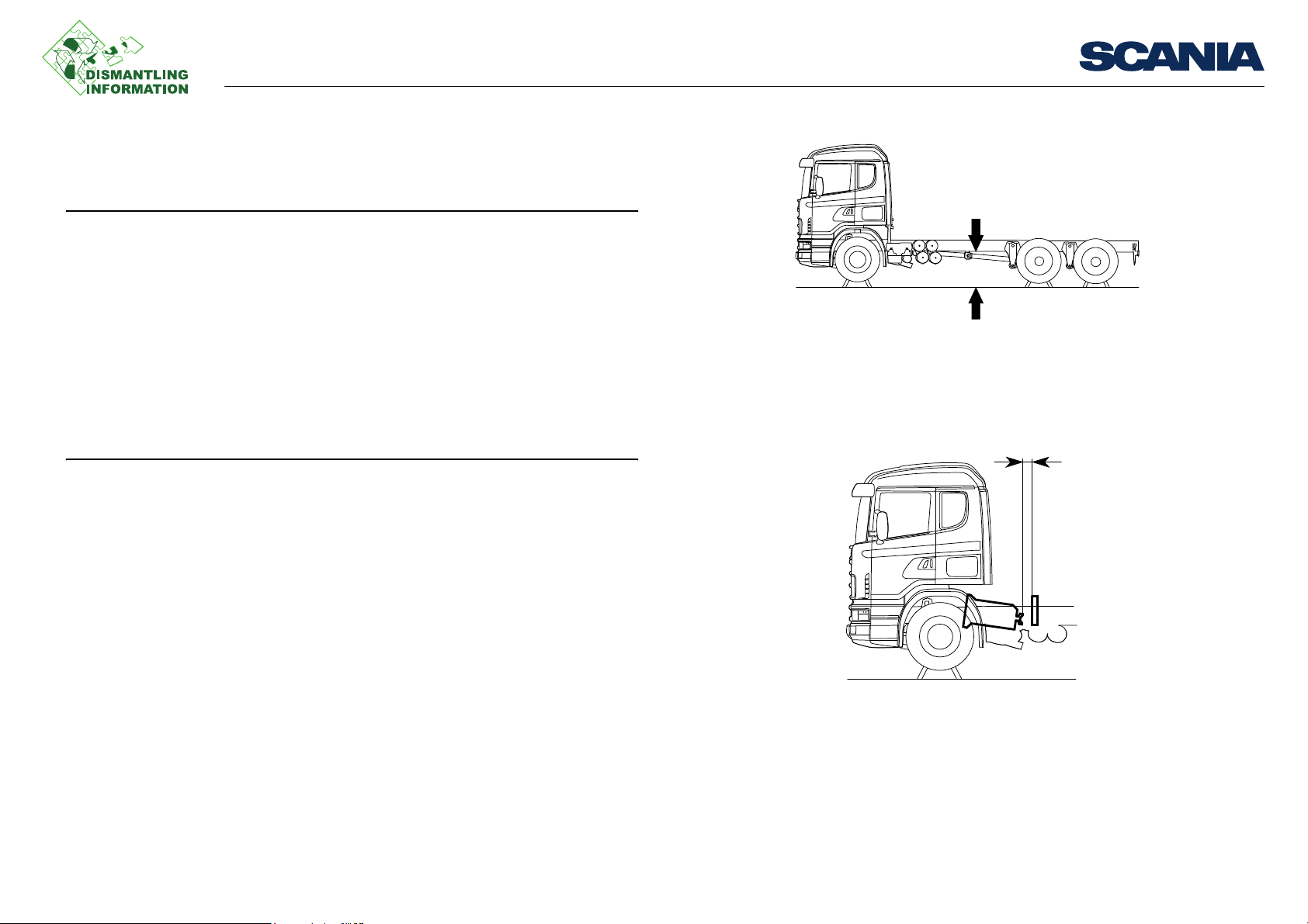
Minimum height between chassis and floor in which to remove the gearbox is approx. 1 meter.
Minimum distance behind gearbox in which to remove it is approx. 150 mm.
Work description
03:65-00 Issue 1 en-GB 3 (11)
©
Scania CV AB 2012, Sweden
Page 4
Removing a manual gearbox
106 095
85
85
40
123 053
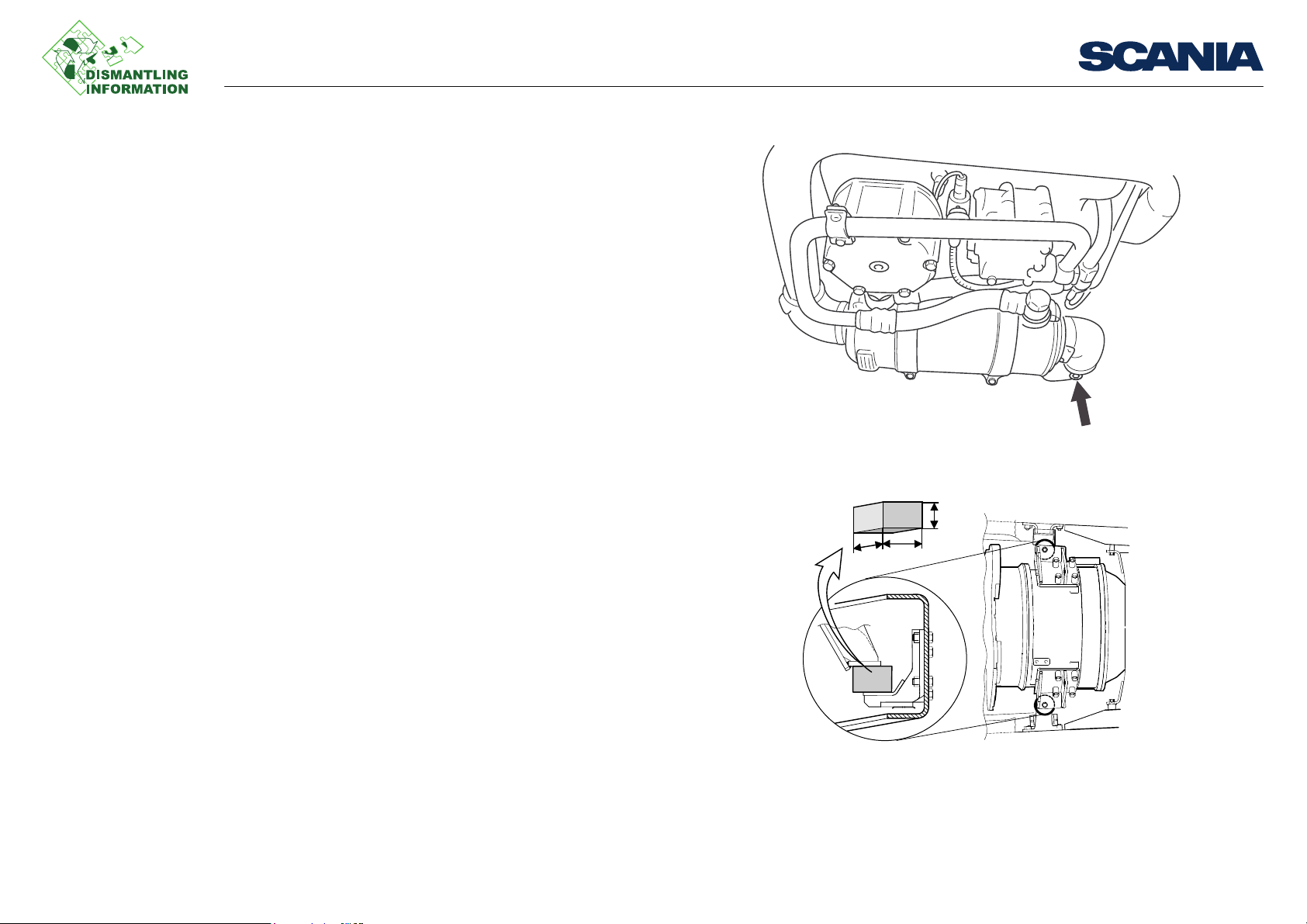
Gearbox with torque converter
• Drain the coolant from the torque converter by undoing the drain nipple on the
illustration.
• The torque converter must be supported when the power train is raised, see illustration. Replace the rubber cushions on the torque converter with 85x85x40 mm
wooden blocks when supporting.
Work description
03:65-00 Issue 1 en-GB 4 (11)
©
Scania CV AB 2012, Sweden
Page 5

Removing a manual gearbox
Vehicles with all-wheel drive
• Remove the propeller shafts between the gearbox and transfer gearbox and between the transfer gearbox and front axle.
• Remove the underslung crossmember.
• Remove the hydraulic pipe to the cab tilt cylinder.
Work description
03:65-00 Issue 1 en-GB 5 (11)
©
Scania CV AB 2012, Sweden
Page 6

Removing a manual gearbox
147 273
147 275
A
Gearbox with power take-off EK630/640
1. Detach and place the valve package to one side.
2. Undo connection A for the slave cylinder. Detach and remove the slave cylinder
and its bracket.
Work description
03:65-00 Issue 1 en-GB 6 (11)
©
Scania CV AB 2012, Sweden
Page 7

Removing a manual gearbox
147 277
B C
3. Make sure the bell crank pressure rollers B is free from the clutch release bearing
lugs C when the gearbox is separated from the engine. The release bearing is not
locked.
Work description
03:65-00 Issue 1 en-GB 7 (11)
©
Scania CV AB 2012, Sweden
Page 8

b115351
8 14
9
4
2
99 044587 313
98 655
98 405-2
98 401
13
Removing a manual gearbox
Removing
1. Drain the retarder
2. Drain the gearbox fluid
3. Undo the oil hoses (5)
4. Undo the pipe to the oil filter (4)
5. Remove the propeller shaft and exhaust pipe
6. Detach the air pipe between the solenoid valve and pressure limiting valve (1)
7. Detach the hose from the proportional valve (2)
8. Remove the cable to the speedometer sensor (3)
9. Detach the gear control (6)
10. Undo the torque rod (7)
11. Split the multi-pin connector (8)
12. Undo the clutch servo hose (9)
13. Remove the shock absorber (10)
14. Remove the accumulator
15. Support the engine
16. Attach the gearbox to the rear gearbox support (13)
17. Screw the vibration insulators up about 10 mm (12)
18. Raise the powertrain to relieve the pressure on the gearbox brackets
19. Undo the gearbox brackets (14)
20. Lower the powertrain
21. Remove the clutch housing nuts (11)
22. Undo the retaining ring on the clutch
Work description
03:65-00 Issue 1 en-GB 8 (11)
©
Scania CV AB 2012, Sweden
Page 9

b115352
1
3
7
6
14
11
12
5
10
Removing a manual gearbox
Work description
23. Remove the gearbox
Draining the retarder
Lower the air suspension to its lowest point.
Tilt the cab.
1. Drain the coolant using adapter 99 301 and coolant tank 588 450.
2. Drain the remaining coolant through drain plug 1 on the retarder left-hand cool-
ant pipe by the clutch housing.
3. Drain the oil from the retarder oil cooler.
03:65-00 Issue 1 en-GB 9 (11)
©
Scania CV AB 2012, Sweden
Page 10

Removing a manual gearbox
IMPORTANT!
05_5402
2
4
3
1
Support the engine
When working on removing and fitting a gearbox, the engine in the vehicle should
be supported.
Never alter the distance between the front axle beam and frame, e.g. by raising the
air suspension. There is a risk that the engine will drop.
1. Secure engine support (1) 99 318 on the front axle beam. On vehicles with all-
wheel drive a U-beam manufactured in-house must be used. Make sure that the
protruding parts of the beam side pieces end up on the outside of the leaf springs.
2. Screw on the lowest spacing sleeve (2) f necessary. On vehicles with all-wheel
drive the lower spacing sleeves should be used on both sides.
3. Unscrew two screws on the oil sump. Select the screws so that the intermediate
sleeve ends up behind the centre of the front axle. On vehicles with all-wheel
drive the two screws at the very back on the sides of the oil sump should be removed.
4. Adjust with intermediate sleeves (3) so that the threaded adjusting device pins
can be fitted into the screw holes. On vehicles with all-wheel drive, the oil sump
design means that on the right-hand side there is only room for the shortest intermediate sleeve and the adjusting device must be screwed out further. On the lefthand side there is room for a longer intermediate sleeve.
5. Adjust the position of the sleeves so that they are as straight as possible and tight-
en the nuts on the lowest spacing sleeve.
6. Screw up the adjusting device (4) so that the support bottoms against the oil
sump.
Work description
03:65-00 Issue 1 en-GB 10 (11)
©
Scania CV AB 2012, Sweden
Page 11

Removing a manual gearbox
Detach the clutch retaining ring
1. Pull the gearbox backwards 10-15 mm.
2. Plug the slave cylinder. Use plug 813 876 and union nut 812 888.
3. Carefully push the gearbox back towards the propeller shaft flange, so that the
retaining ring is relieved of pressure.
4. Compress the retaining ring wire ends until the end of the slave cylinder is re-
leased from the diaphragm spring joint. Allow the pliers to remain in place. Use
pliers 587 585 with tips 99 302. A cable tie may be used instead of the pliers to
hold the wire ends of the retaining ring together.
Work description
03:65-00 Issue 1 en-GB 11 (11)
©
Scania CV AB 2012, Sweden
 Loading...