

Page 1

December 2017, en-GB
Dismantling information
P, G, R and S series
Page 2

Page 3

Table of contents
General............................................................................................................................. 1
Dismantling information ..................................................................................................1
Exchange components ...................................................................................................3
Hazardous substances and materials...............................................................................4
Identification of plastics ...................................................................................................9
Lifting and supporting on stands ....................................................................................27
Engine ............................................................................................................................ 38
Engine.........................................................................................................................38
Oil filter .......................................................................................................................41
Rotor ...........................................................................................................................43
Engine oil.....................................................................................................................45
Cooling system ............................................................................................................. 46
Coolant........................................................................................................................46
Fuel and exhaust systems ........................................................................................... 50
Dismantling the silencer ................................................................................................ 50
Reductant tank .............................................................................................................54
Fuel tank......................................................................................................................57
Coupling......................................................................................................................... 60
Connection and operation .............................................................................................60
Gearbox.......................................................................................................................... 63
Gearbox ...................................................................................................................... 63
Brakes - Pneumatic system ......................................................................................... 65
Compressed air tanks ..................................................................................................65
Spring brake chamber...................................................................................................66
Suspension.................................................................................................................... 68
Air suspension .............................................................................................................68
Steering.......................................................................................................................... 71
Removal - Airbag.......................................................................................................... 71
Electrical system........................................................................................................... 75
Chassis central electric unit ..........................................................................................75
Removal - Curtain airbag...............................................................................................77
Batteries ......................................................................................................................81
Page 4

Instrument...................................................................................................................... 83
Removal - Instrument panel...........................................................................................83
Cab - Body - Canopy..................................................................................................... 93
Cab tilt system ............................................................................................................. 93
U4, Refrigerator............................................................................................................95
A/C compressor ...........................................................................................................97
Working with refrigerant ................................................................................................99
Compressor - auxiliary cab cooler (E114) .....................................................................101
Page 5

General - Dismantling information
General
Dismantling information
General
This information is aimed at everybody dealing with reconditioning and scrapping of Scania vehicles. The
information applies to workshops, dismantling and recycling companies.
The information is applicable to new Scania models. However, not all parts are covered by this
information booklet. The information is incomplete.
Draining and removing describes how environmentally hazardous waste should be separated from the
vehicle (pre-treatment).
Identification of materials is to facilitate identification and sorting of material for recycling.
Colours and a material code identify polymer materials. Parts consisting of two plastic materials are twocoloured. Where there are more than one variant of a part, the codes of both materials will be stated.
Scania and the environment
Scania works continuously towards products, processes and services with reduced impact on the
environment. The environmental work therefore focuses on doing the right thing from the beginning, and
reducing the consumption of resources such as base materials and energy.
By including environmental aspects in the product development from an early stage, the product's impact
on the environment can be reduced during the whole life cycle - from research and development, via
production and usage, to end-of-life treatment. Lower fuel consumption and reduced exhaust emissions
are always in focus. An environmentally appropriate end-of-life treatment can be made possible by
adapting the design solutions, by choosing materials with little environmental impact, and by avoiding
hazardous materials.
A more environmentally friendly production is obtained by, among other things, reducing the consumption
of water, chemicals, base materials and energy. Residual products such as chips and scrap are utilised.
Scania supports its customers in choosing the right vehicle for a certain transport task. This reduces both
fuel consumption and wear. Scania can also assist with driver training and inspection programmes.
Correct maintenance is important in order to maintain the environmental characteristics of the vehicle.
About 1,500 Scania workshops are found around the world to provide this.
Dismantling information and correct marking of components and materials facilitate end-of-life treatment.
End-of-life treatment of vehicles
With the ever increasing global population and economical development, efficient usage of the resources
is becoming more and more important. Material reuse and recycling are two ways to contribute to efficient
usage of resources.
Scania's involvement in end-of-life treatment issues aims for responsible, environmentally responsible
and resource-efficient after-life management of Scania vehicles.
End-of-life treatment comprises a number of procedures that the vehicle must undergo, for example:
• Pre-treatment: E.g. draining fluids, emptying climate control systems and removing batteries
• Re-use: Parts, reconditioned or non-reconditioned, are being re-used after removal. Scania has its own
service exchange system.
December 2017, en-GB © Scania CV AB
1
Page 6

General - Dismantling information
• Recycling: The material is re-used in the production of new products with the same or a lower quality
rating.
• Energy recovery: Combustion with energy recovery.
Only disposal remains if none of the above alternatives is possible.
2
© Scania CV AB December 2017, en-GB
Page 7

General - Exchange components
Exchange components
General
As part of its efforts to be environmentally-friendly, Scania offers a wide range of Service Exchange
components. Units that have been returned are reconditioned so as to have the same technical status as
a new part. Scania Service Exchange is a sustainable way of reducing harmful carbon dioxide emissions,
energy use and consumption of raw materials.
Exchange components have the same warranty as other spare parts.
Ordering exchange components
Exchange components are ordered from Scania in the same way as other spare parts. Orders for spare
parts and exchange components can be placed on the same order.
Scania service exchange system
For more information about the Scania service exchange system, you can contact a Scania dealer or a
Scania workshop.
December 2017, en-GB © Scania CV AB
3
Page 8

General - Hazardous substances and materials
Hazardous substances and materials
The following list is a guide of lubricants, fluids and parts that are recovered from the truck during pretreatment. Volumes are approximate.
ENVIRONMENT
Avoid spillage and use a receptacle when handling
hazardous fluids
Engine:
7-9 litre engine
D9/13 XPI Fuel filter housing, diesel
D9/13/16 XPI
13 litre engine
D16 XPI
D13 PDE
16 litre engine
Cooling system: Specification: Quantity:
7-9 litre engine
13 litre engine
16 litre engine
Chassis: Specification: Quantity:
Fuel tank Diesel
Specification: Quantity:
Oil
High pressure fuel pump, oil
Oil
Fuel filter housing, engine,
diesel
Fuel filter housing
Oil
Coolant
Coolant
Coolant
27 - 38 litres
0.4 l
0.3 l
40 - 44 litres
0.2 l
0.3 l
32 - 47 litres
30-52 litres
40-62 litres
45-102 litres
-
Steering: Specification: Quantity:
Steering axle
Gearbox: Specification: Quantity:
Gearbox Oil
Transfer gearbox
Opticruise, longitudinal stroke
damper
Retarder
M33 electric machine
4
Transmission oil, ATF 2.2 litres
13-50 litres
Oil
Oil
Oil
Oil
© Scania CV AB December 2017, en-GB
6.5 litres
0.09 litres
approx. 7.5 litres
5.5 litres
Page 9

General - Hazardous substances and materials
Axle gear:
Axle gear
Axle gear with bogie gear
Portal axle (ZF) Oil
Hub:
Hub reduction gears
ZF hub
Specification: Quantity:
Oil
Oil
9-13 litres
11-12 litres
19.5 litres
Specification: Quantity:
Oil
Oil
2 litres
0.7 litres
Cab: Specification: Quantity:
Refrigerator Refrigerant R134a
Auxiliary cab cooler
A/C
Airbag (H14)
Safety belt with belt pretensioner
Refrigerant R134a
Refrigerant R134a
- -
- -
30-47 g
approx. 1,200 g
(H16, H17)
Side curtain airbags (H30, H31)
- -
Cab tilt system: Specification Quantity
Pump and cylinder Pentosin oil 1.7-2 l
Electrical parts:
Battery, VPS
Starter battery
Battery cable terminals Lead, brass
Wheel
Balancing weights
Specification Quantity
- -
- -
-
Specification Quantity
- -
December 2017, en-GB © Scania CV AB
5
Page 10

General - Hazardous substances and materials
Isocyanates
WARNING!
Isocyanates are found in some paints, putty, adhesive
and plastic foams that are used in motor vehicles.
Inhaling isocyanates in the form of vapour, dust or
aerosols may cause irritation of mucous membranes
causing asthmatic symptoms from the respiratory
passages and an impaired function of the lungs.
Even brief exposure to high concentrations can
cause problems of permanent hypersensitivity
When products containing isocyanates in combined
form are heated to temperatures above 150°C,
isocyanates are released. This results in a high
degree of exposure. This applies for example to
grinding, welding and cutting products to which a top
coat of paint containing isocyanates has been
applied. For this reason, make sure that there is
adequate ventilation in the areas where the work is
carried out. Personnel carrying out such work should
use protection such as respiratory masks with air
supply.
Do not take any risks when carrying out work
involving heating materials that may contain
isocyanates; always presume that the material
contains isocyanates and take the necessary safety
precautions.
6
© Scania CV AB December 2017, en-GB
Page 11

Vehicle fires
WARNING!
Where a vehicle is involved in a fire, a number of
substances that are hazardous to health and the
environment are formed. Smoke and water carry
these substances and to a certain extent they remain
in the vehicle (ashes).
Use protective equipment such as respiratory
protective equipment and gloves when working on
vehicles that have been involved in a fire. Avoid skin
contact with ashes.
When dismantling a vehicle that has been involved in
a fire, the following must be taken into consideration:
General - Hazardous substances and materials
The vehicle may be weakened, which can have a
negative affect on lifting points. This should also be
taken into consideration when tilting cabs.
Gas dampers which have not been punctured
represent an explosion risk, as the material they are
made of may be weakened or damaged.
Wash the vehicle before starting dismantling.
Keep the following in mind:
Do not start dismantling before the cause of the fire
has been fully investigated.
Power should be disconnected on vehicles which
have been involved in a fire as soon as possible, by
disconnecting the battery cables. This is to prevent
short circuits, which can result in a new fire.
Corrosion is accelerated on vehicles which have
been involved in a fire, for example due to moisture in
combination with ashes and some extinguishing
agents. The vehicle should be processed as soon as
possible, to minimise the risk of undesirable leakage
of environmentally hazardous fluids and substances.
Fire damaged vehicles should be washed in a way
that allows the washing water to be disposed of in an
environmentally responsible way, as it contains
environmentally hazardous contaminants
December 2017, en-GB © Scania CV AB
7
Page 12

General - Hazardous substances and materials
IMPORTANT!
When carrying out any type of work which involves
heating products, the relevant safety regulations for
this type of work should be followed.
Cut the power to the vehicle before starting work.
When working with air bellows, the system must not
be pressurised.
8
© Scania CV AB December 2017, en-GB
Page 13
General - Identification of plastics
Identification of plastics
Plastics are divided into 2 main groups; meltable (thermoplastics) and non-meltable (thermosets).
Thermoplastics are cast or injection moulded and unlike thermosets they lack bonds between the plastic
molecules. Thermoplastics can be recycled with good results.
Thermoplastic recycling is a good way to conserve base materials and save money. There are different
types of thermoplastics and it is important to keep them separate during recycling work so that the
mechanical properties of the recycled material are not impaired. Certain material combinations can be
compensated using additives that make the plastics miscible. Mixing in new base material can also
improve the properties.
Parts made of thermoplastic
Parts made of thermosets
December 2017, en-GB © Scania CV AB
9
Page 14

General - Identification of plastics
Examples of plastics that are not suitable for mixing are listed in the table below:
Base material
ABS
ABS
PA B A B
PBT A B A A A A B B B
PC
PC
+ABS
PC
Mixing material
+PBT
PE
PMMA A B B A A A B A B B
PP
PVC
=
A
B
C
Compatible
=
Compatible in purer mixtures (<5%)
=
Incompatible
A B A A A A
A
A B A A A A B A B
A
C
C
A
PA PBT
C
C
B
B
C C C C C
A A A A B A B
A A A A B A B
C
C C C C
PC PC
+ABSPC+PBT
C C C
B
C C
PE PMM-APP
C
B B B
A
B A B A
B A B A
A
C
C
A B
PVC
A
C
C
C
C
C
Painting thermoplastics is disadvantageous with respect to recycling even though there are methods of
separating the paint. Plastics age and become brittle. Take a random sample for measuring the melting
index to see how far degradation has advanced. See ISO 1133.
Pure plastic that does not contain a high degree of other material (maximum 5% of another plastic), and
has not degraded due to long periods of damp or heat treatment can be classified as new plastic, though
with reduced properties.
Mixed material or material with molecules degraded to short chains can only be reshaped to very simple
products or used for energy recovery.
Thermosets are plastic prepared with hardeners which bind the plastic molecules to each other.
Thermosets are strong and rigid but brittle. Therefore it is often reinforced with for example glass fibre
mat.
Thermosetting plastics are more difficult to recycle as it is not possible to melt and reshape them. The
methods of recycling available today are energy recovery and, to a certain degree, pulverisation for filling.
Marking of plastics
Scania marks all its plastics (where there is space for a mark) in compliance with Scania Standard STD
387, which in turn is based on ISO 11469 - Generic identification and marking of plastic products.
The marks consists of international designations according to the following standards:
ISO 1043 Plastics - Symbols and abbreviations
ISO 1433 Vulcanised rubber - Choice of required properties
ISO 1629
10
Rubber and latex -Terminology
© Scania CV AB December 2017, en-GB
Page 15

General - Identification of plastics
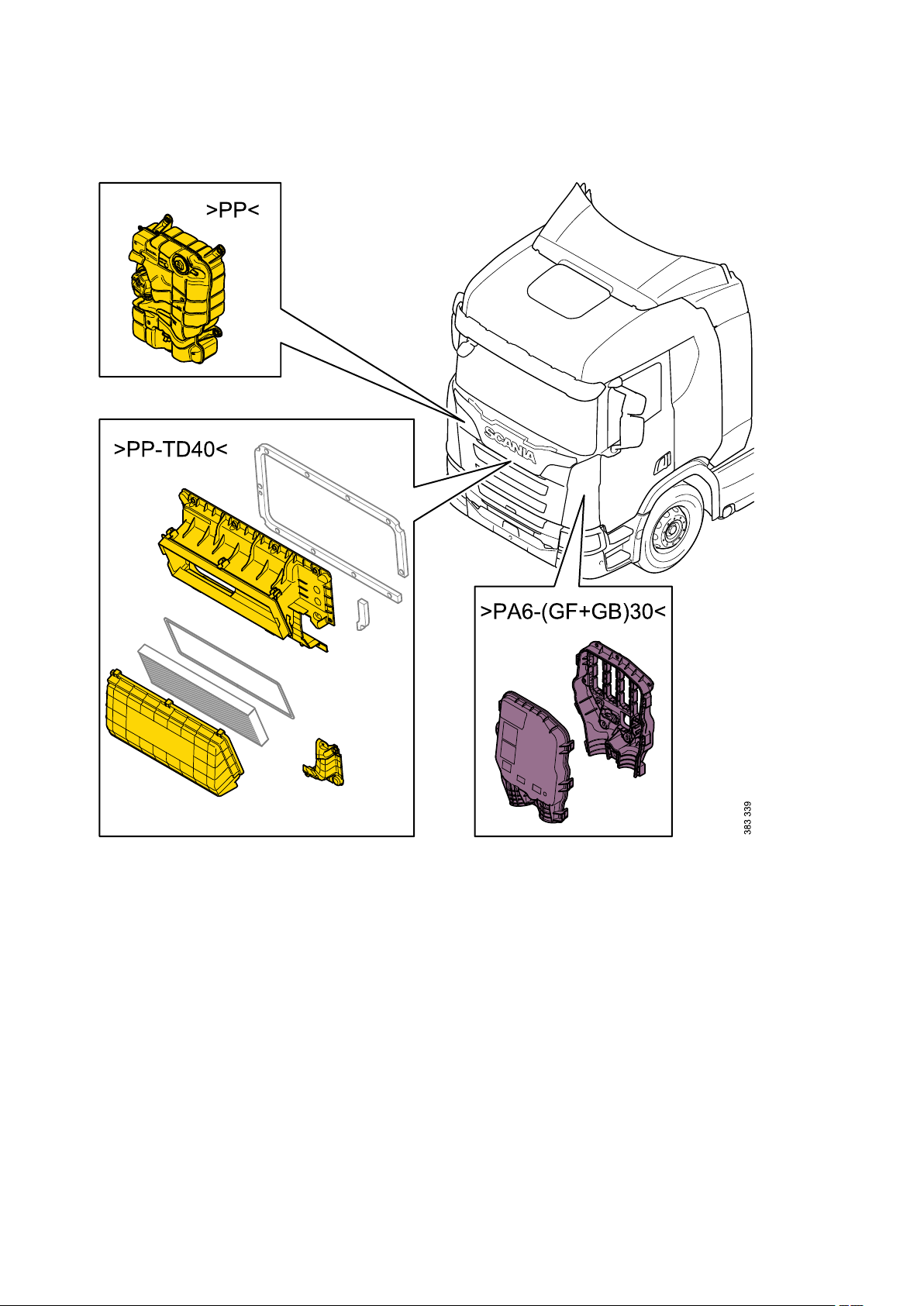
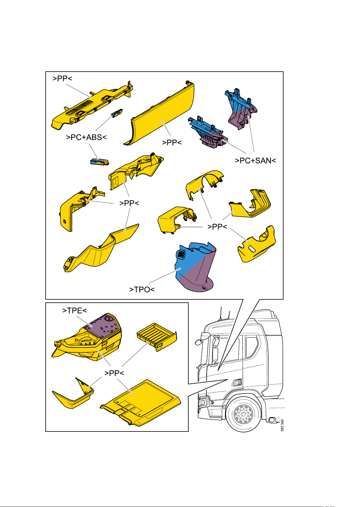
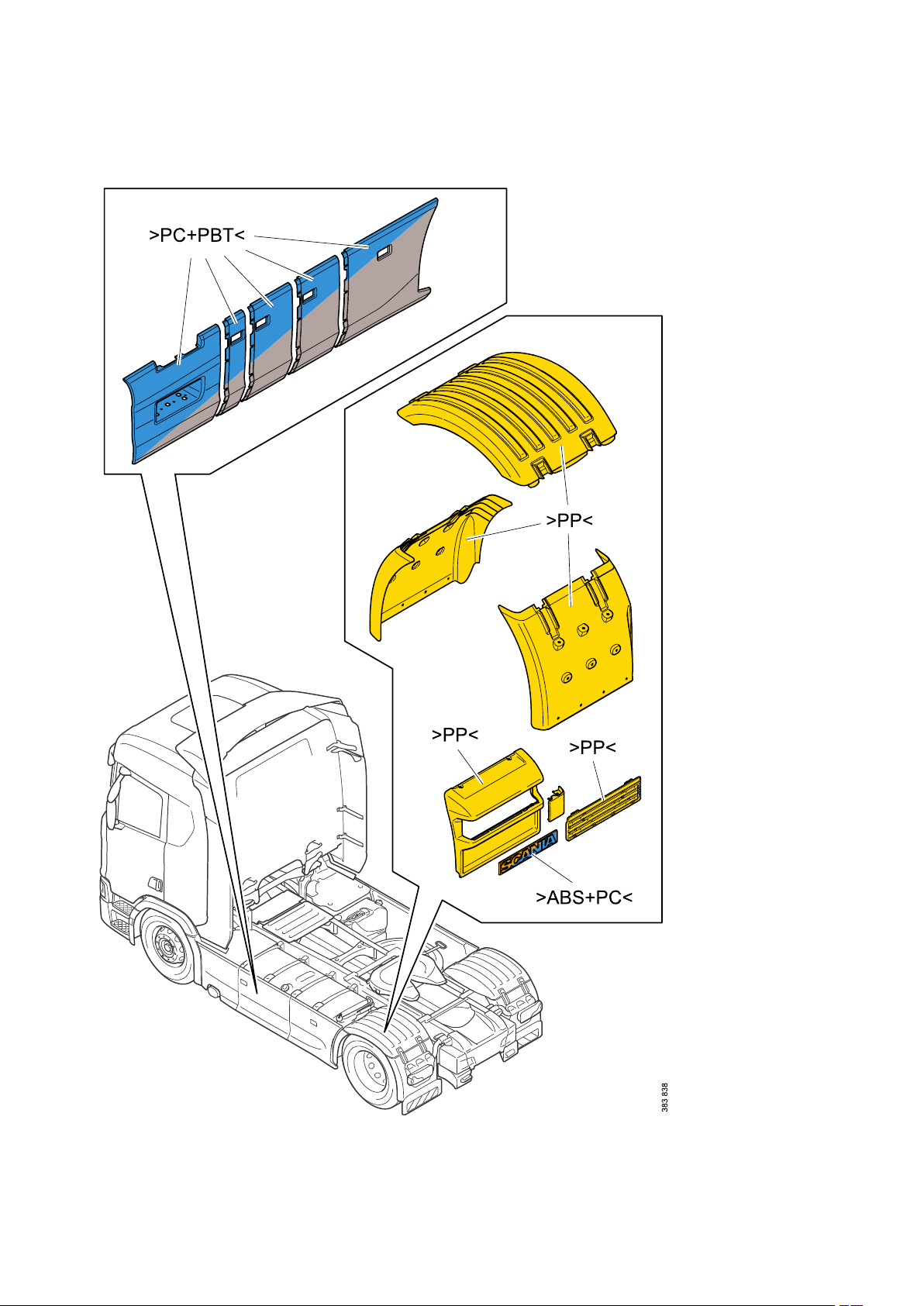
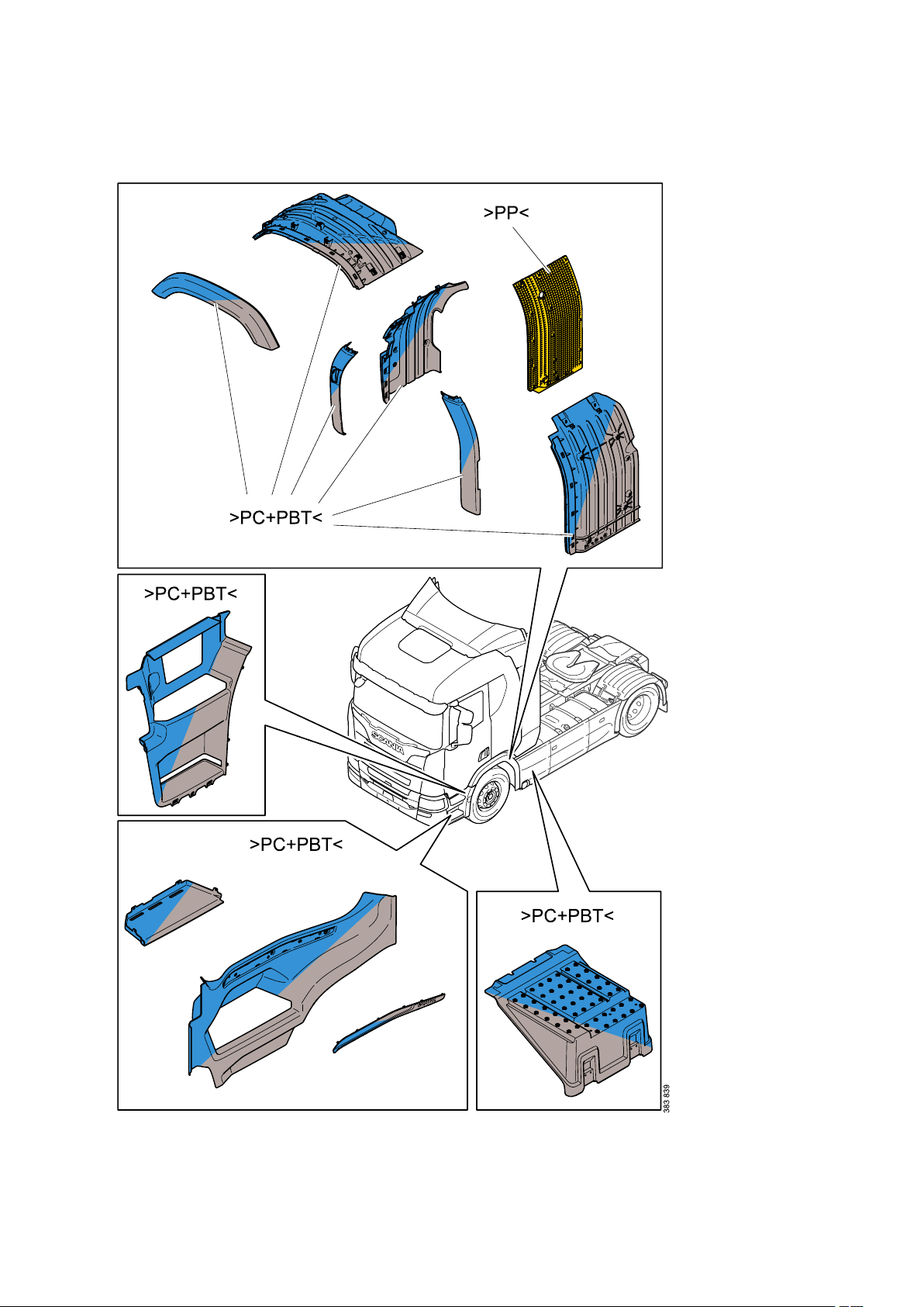
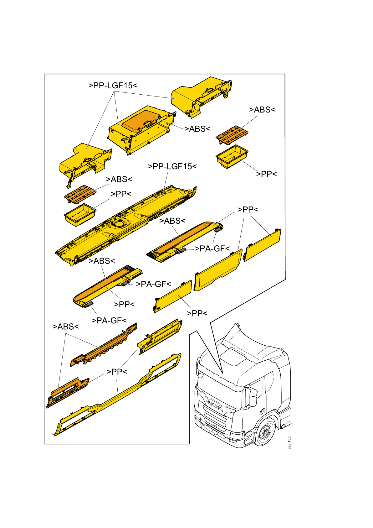
The marks start and finish with the arrow symbols > and <.
The following is a brief description of the thermoplastics most commonly used by Scania. Plastics are
designated by 2 to 4 capital letters (e.g. >ABS<) and sometimes a mixture of 2 materials (e.g. >ABS
+PC<).
There are often fillers (T for Talcum powder, M for Mineral and G for Glass) and the amount of filler as a
percentage (e.g. >ABS-T20<, which means ABS with 20% talcum powder).
Part numbers are necessary for identification of parts in production as well as for maintenance and spare
parts. Part numbers comprise a five, six or seven digit serial number, e.g. 1234567-LH (part number - lefthand).
The marked date refers to the date of manufacture. The marked date often comprises a date and a time
or just a date field.
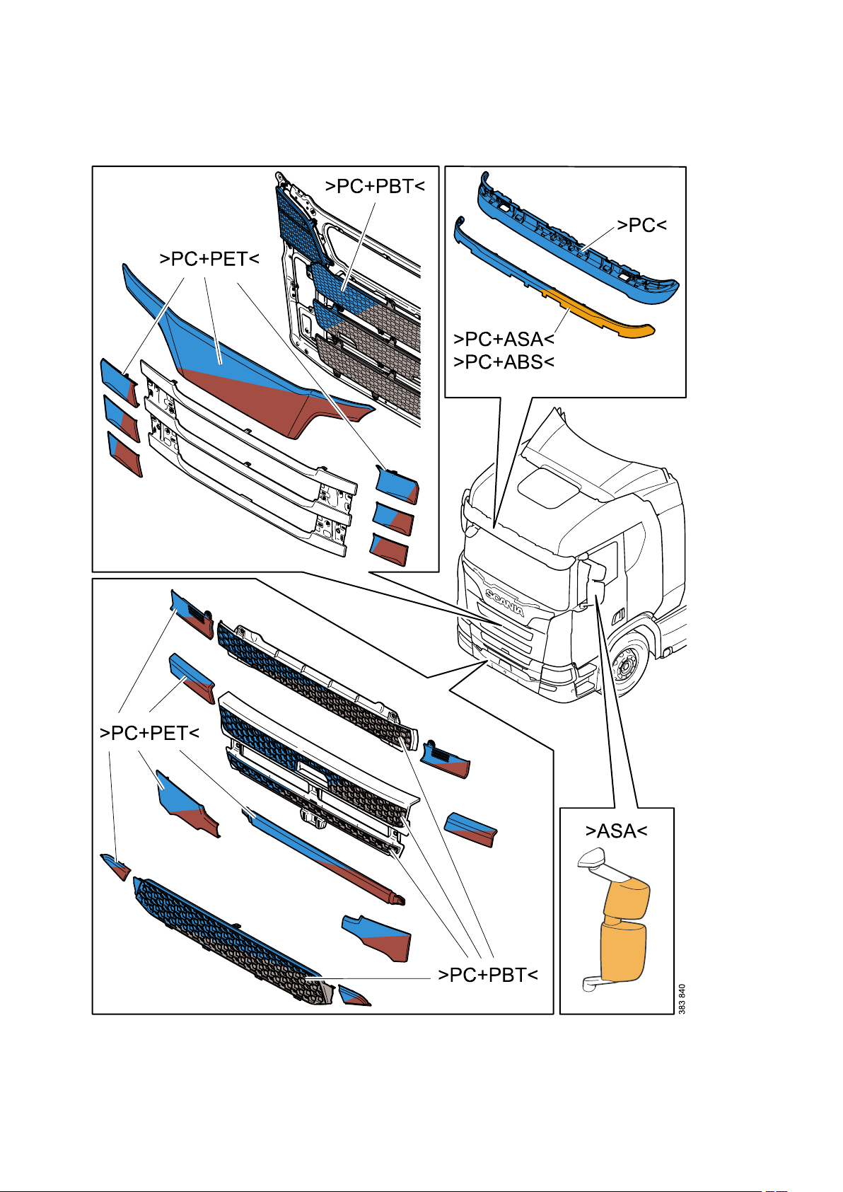
Plastics designations
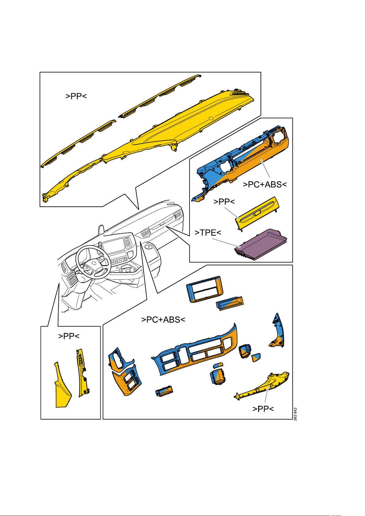
>ABS<
Acrylonitrile butadiene styrene:
ABS is easy to recycle and can be mixed with PC to form PC+ABS after recycling, which is advantageous
since pure ABS can loose impact resistance when remelted.
>ASA<
Acrylonitrile styrene acrylate:
Used for A-pillar panels, windscreen wiper panels, hinge covers, rear view mirror holders and roof hatch
panels. Weather and colour resistant. Easy to recycle.
>EPDM<
Ethylene propylene diene monomer (rubber).
>HDPE<
High density polyethylene.
NR
Nitrile rubber.
>PA<
Polyamide:
The designation is often followed by one of the figures 6, 6.6, 11 or 12. Used primarily for engine
compartment components, compressed air and fuel pipes. Recycling is limited by the availability of
material. Material properties are not impaired to any significant degree as long as the recycling process
takes into account the problems of moisture.
>PBT<
Polybutyleneterephthalate:
Recycling is limited by the relatively small amounts of material available and the lack of material data
collected from recycled material.
December 2017, en-GB © Scania CV AB
11
Page 16

General - Identification of plastics
>PMMA<
Polymethylmethacrylate:
Better known as plexiglas. Used primarily for covers for lighting and instruments. Easy to recycle.
>PC<
Polycarbonate:
At Scania, we use PC in exterior sun visors and as lenses. PC is often used in combination with ABS,
PBT, PETor ASA.
>PC+PBT<
A mixture of PC and PBT, combining the best characteristics from both materials. It is sensitive to
moisture and high temperatures during manufacturing.
Recycling is difficult to assess as the material degrades at high temperatures and after exposure to
moisture for long periods.
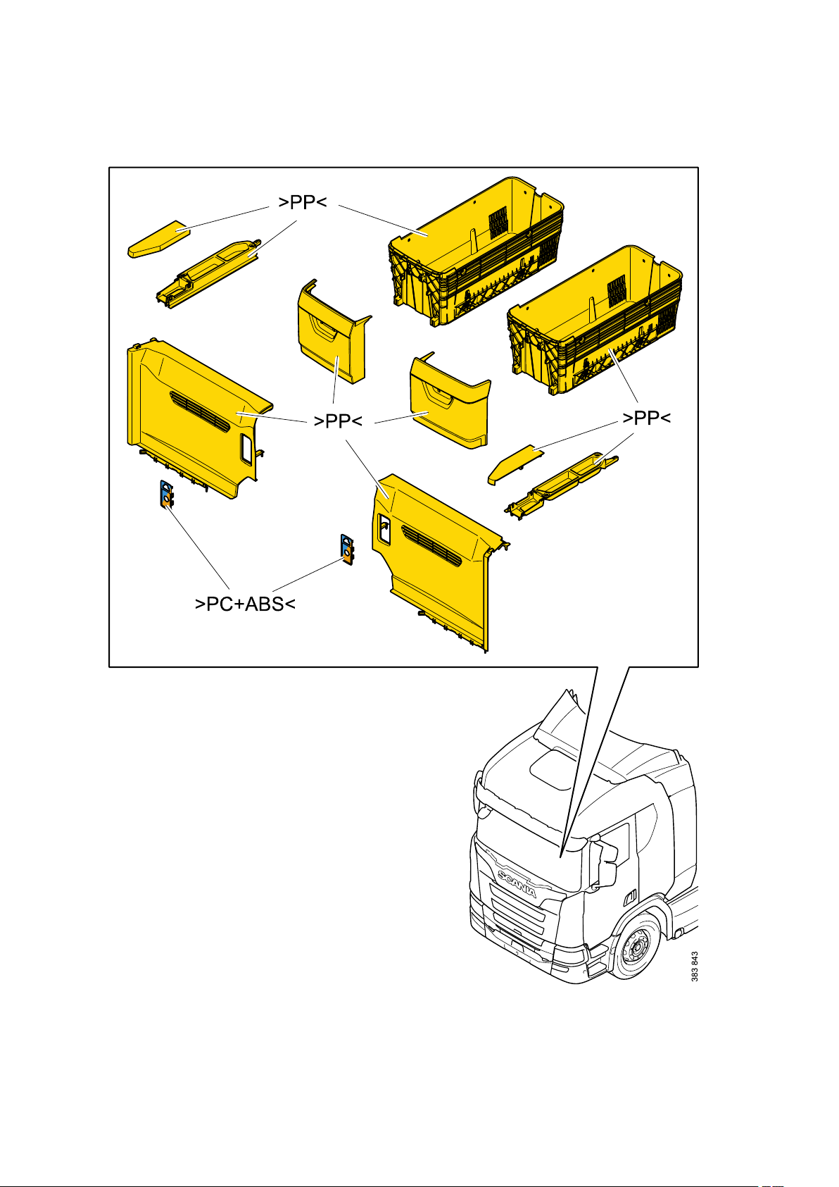
>PC+ABS<
A mixture of PC and ABS. Recycling is easier than PC+PBTand works well for material for simpler
products.
>PE<
Polyethylene:
Several designations can occur depending on the density:
• PE - LD where LD means Low Density
• PE - HD where HD means High Density
Used for certain fuel tanks, etc. Polythene is the most recycled material in the world. The material
absorbs fuel which later, and if recycled, emits odour. Material from fuel tanks should therefore undergo
special treatment and be used for energy recovery.
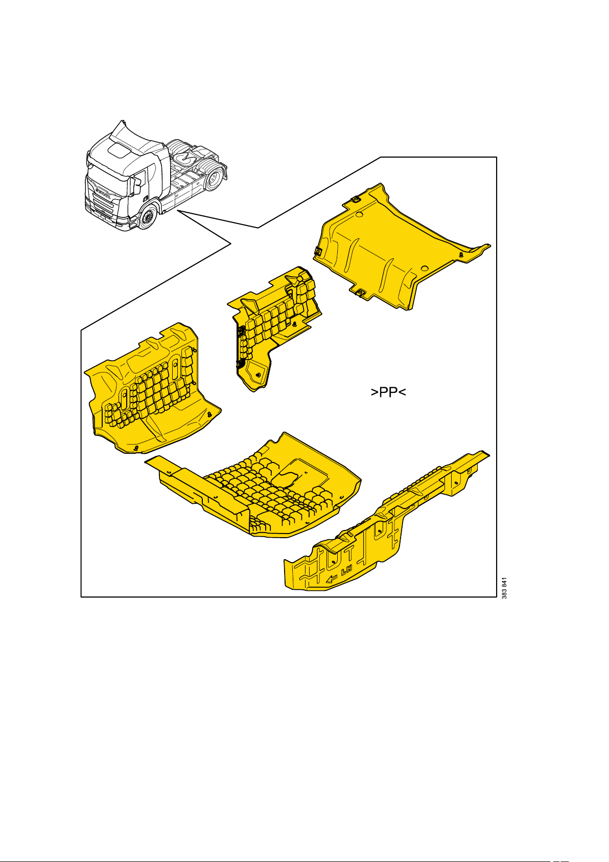
>PP<
Polypropylene:
Normally used for interiors, in low temperature applications around the engine and even externally in
some cases. PP is easy to recycle.
>PUR<
Polyurethane (Thermosets):
Used in squab cushions, armrests and noise reduction mats. This material is difficult to recycle at
present.
>PVC<
Polyvinyl chloride:
Used for cable insulation, for example. This material is difficult to recycle as it is sensitive to impurities. It
also forms hydrochloric acid during incineration.
>TPE<
Thermoplastic elastomer (rubber).
12
© Scania CV AB December 2017, en-GB
Page 17

General - Identification of plastics
>UP<
Unsaturated polyester (Thermosets):
At Scania, UP is used mostly as pressed SMC - Sheet Moulding Compound. SMC is a semi-finished
product comprising fibres (usually glass fibres) and UP mixed with filling, release agent, hardener and
sometimes paint. Used most often for air deflector kits and exterior panels.
Overview illustrations
Colour codes
"other" = other polymer materials
December 2017, en-GB © Scania CV AB
13
Page 18

General - Identification of plastics
14
© Scania CV AB December 2017, en-GB
Page 19
General - Identification of plastics
December 2017, en-GB © Scania CV AB
15
Page 20
General - Identification of plastics
16
© Scania CV AB December 2017, en-GB
Page 21
General - Identification of plastics
December 2017, en-GB © Scania CV AB
17
Page 22
General - Identification of plastics
18
© Scania CV AB December 2017, en-GB
Page 23
General - Identification of plastics
December 2017, en-GB © Scania CV AB
19
Page 24
General - Identification of plastics
20
© Scania CV AB December 2017, en-GB
Page 25
General - Identification of plastics
December 2017, en-GB © Scania CV AB
21
Page 26
General - Identification of plastics
22
© Scania CV AB December 2017, en-GB
Page 27
General - Identification of plastics
December 2017, en-GB © Scania CV AB
23
Page 28
General - Identification of plastics
24
© Scania CV AB December 2017, en-GB
Page 29
General - Identification of plastics
December 2017, en-GB © Scania CV AB
25
Page 30
General - Identification of plastics
26
© Scania CV AB December 2017, en-GB
Page 31

General - Lifting and supporting on stands
Lifting and supporting on stands
Safety precautions
WARNING!
Never work under a vehicle only supported by a jack!
IMPORTANT!
Never support on stands or lift a raised vehicle on
parts belonging to the wheel suspension or steering.
Never support on stands or lift underneath the torque
rods or their brackets.
WARNING!
Use reliable and correctly dimensioned axle stands,
struts and locks with standard locking devices.
Ensure that the jack and stands are stable on a level
surface.
WARNING!
Always empty the air bellows or support the frame on
stands before starting work under vehicles with air
suspension. See the Work on vehicles with air
suspension section.
Raising with a jack
NOTE:
Read the safety precautions before starting work!
December 2017, en-GB © Scania CV AB
27
Page 32

General - Lifting and supporting on stands
IMPORTANT!
Lifting under the front axle or rear axle is only
permitted on an unladen vehicle.
Lifting using a jack under driving axles with a high
axle weight can cause the axle housing and gear
housing to become deformed.
No load must be placed on the oil drain plug.
IMPORTANT!
When lifting vehicles with several front axles or rear
axles, the axle weight distribution must be taken into
account.
1.
WARNING!
Chock the wheels and release the parking brake
before jacking up the vehicle, so that the vehicle can
follow the movement of the jack.
Chock the wheels to prevent the vehicle rolling
away and release the parking brake.
2. Lift the vehicle under any of the lifting points
IMPORTANT!
A laden vehicle can only be lifted under the spring
mountings.
3. Secure the vehicle on axle stands.
28
© Scania CV AB December 2017, en-GB
Page 33

General - Lifting and supporting on stands
Raising with wheel lifts
WARNING!
Always empty the bellows before lifting with wheel
lifts.
If there is a loss of air pressure, the axle distance will
change, which can cause the wheel lifts to tip over.
Vehicles with air suspension:
Empty the bellows of air according to Work on vehicles with air suspension.
Supporting on stands under the axle
Front
Always raise all axles with wheel lifts.
Supporting under the axle, front
December 2017, en-GB © Scania CV AB
29
Page 34

General - Lifting and supporting on stands
Rear
Supporting under the axle, rear
Vehicles with leaf spring suspension can also be supported under the springs.
Supporting the vehicle on stands, front
NOTE:
Read the safety precautions before starting work!
1. Remove the air deflector, if fitted, by unscrewing the
screws at the front edge and then unhook the air
deflector from the rear brackets.
2. Raise the vehicle on jacks or wheel lifts.
30
© Scania CV AB December 2017, en-GB
Page 35

3. Place axle stands under the jacking points.
General - Lifting and supporting on stands
4. Lower the vehicle carefully, making sure that it is
secure on the axle stands.
Supporting vehicles with a heavy-duty front on stands
NOTE:
Read the safety precautions before starting work!
Without tools
1. Raise the vehicle on jacks or wheel lifts.
2. Remove the inner rear screws securing the corner
plates.
3. Place axle stands under the jacking points.
4. Lower the vehicle carefully, making sure that it is
secure on the axle stands.
December 2017, en-GB © Scania CV AB
31
Page 36

General - Lifting and supporting on stands
With tools
1. Raise the vehicle on jacks or wheel lifts.
2. Remove the corner plates.
3. Screw tool 99 363 in place.
4. Place axle stands under the jacking tools.
5. Lower the vehicle carefully, making sure that it is
secure on the axle stands.
Supporting vehicles with front underrun protection on stands
NOTE:
Read the safety precautions before starting work!
1. Raise the vehicle on jacks or wheel lifts.
2. Place axle stands under the jacking points.
IMPORTANT!
Only support with stands under the underrun
protection on an unladen vehicle.
32
© Scania CV AB December 2017, en-GB
Page 37

General - Lifting and supporting on stands
3. Lower the vehicle carefully, making sure that it is
secure on the axle stands.
Supporting on stands under rear frame
NOTE:
Read the safety precautions before starting work!
If there is space, supporting the vehicle on stands in front of the axle is permitted. In this case position the
stand as close to the axle as possible.
Position the stands on the frame behind the last rear axle.
On vehicles with the battery at the rear and air suspension, the axle stands can be positioned between
the rear axle and the air bellows.
Supporting vehicles with air suspension, rear
Always use the safety prop when working in a pit under vehicles with air suspension. If the air bellows
fails, this can result in personal injury.
WARNING!
The safety prop must always be fitted parallel on the
left and right sides.
December 2017, en-GB © Scania CV AB
33
Page 38

General - Lifting and supporting on stands
IMPORTANT!
The vehicle must not be driven when the safety prop
is fitted.
Fitting the safety prop to vehicles with air suspension
The safety prop is available in 2 lengths, short: 99 678 and long: 99 677.
Fit the safety prop between the spring shackle and frame. The load on the axles is not to exceed 7.5
tonnes per safety prop.
Clean any dirt from the air spring link before fitting the safety prop.
1. Set the rear air suspension to approximately half of
the air spring height.
2. Fit the safety prop at the top between the screws on
the shock absorber bracket in the frame.
3. Position the foot of the safety prop in front of the air
bellows on the air spring link.
4. Detach the rotary control so that the release button
can be pushed in and then pull the safety prop out to
the correct length.
34
© Scania CV AB December 2017, en-GB
Page 39

5. Finish by tightening the quick extension bar until the
safety prop is stable.
Tighten the rotary control and lock the release
button.
IMPORTANT!
If the air bellows are filled with air during the work, the
safety prop must be adjusted afterwards as
described in steps 4-5.
General - Lifting and supporting on stands
Removing the safety prop
1. Fill the air bellows with air until the safety prop is no
longer under load.
WARNING!
Take care when removing the safety prop, there is a
risk of crush injuries.
Detach the rotary control so that the button on the
safety prop can be pushed in. Push the safety prop
together and remove it.
Maintenance
To ensure that the safety prop can be used safely at all times, the following points must be checked at
regular intervals.
December 2017, en-GB © Scania CV AB
35
Page 40

General - Lifting and supporting on stands
1. Checking screw joints. Check that the screw joints
have not come loose. Max. 7 millimetres of the
thread should be visible (1).
2. Checking the release button. Check that the
release button does not stick and that it goes out to
the locked position. This ensures that it will not
collapse during work.
3. Checking the feet. Check that there is not crack
formation on the safety prop feet.
Also make sure that:
4. The threads are free of dirt.
5. The screws securing the cover are tightened. (See
picture.) This is important, as these bolts also retain
the release button springs.
6. Finally the balls of the joints should be lubricated
with oil if they are stiff.
Renewing the foot on the safety prop
If the feet on the safety prop are damaged or worn, they should be renewed.
1. The threads are locked with adhesive. To unscrew
the feet, heat the thread in a suitable manner.
2. Unscrew the feet.
3. Lock the thread with adhesive.
36
© Scania CV AB December 2017, en-GB
Page 41

4. Fit the new feet. A maximum of 7 millimetres of
thread (1) should be visible.
General - Lifting and supporting on stands
December 2017, en-GB © Scania CV AB
37
Page 42

Engine - Engine
Engine
Engine
Removal - Engine
NOTE:
The gearbox must be removed before removing the
engine.
Tools:
NNuummbbeerr
99 063
98 094
DDeessiiggnnaattiioonn
Lifting yoke
Lifting chain
Picture Tool-board
D4
38
99 611
Lifting eye for V8 engine
© Scania CV AB December 2017, en-GB
Page 43

Engine - Engine
NNuummbbeerr
99 637
587 308 Ratchet lever hoist
99 318
Lifting eye for 9 and 13 litre engines
DDeessiiggnnaattiioonn
Engine support
Picture Tool-board
D5
99 470
2 377 964
1. Tilt the cab in accordance with the applicable safety
precautions. See the section Cab tilt system.
2. Cut the power.
Completing kit for engine support kit
Adapter
99 318
IMPORTANT!
Turn off the power by removing the battery negative
terminals.
3. Detach all pipes and hoses from the engine.
4. Drain the engine of all fluids.
D5
D5
December 2017, en-GB © Scania CV AB
39
Page 44

Engine - Engine
5. Undo the 8 screws. The image shows a V8 engine
but the principle is the same for other engines as
well.
6. Lift off the engine. Use the lifting eyes. The image
shows a V8 engine but the principle is the same for
other engines as well.
IMPORTANT!
V8 engine
The lifting eyes are designed to manage a maximum
inclination angle of 30° when lifting an engine with the
gearbox removed.
1. Lifting eye 99611 for V8 engines
2. Engine-mounted lifting eye
40
© Scania CV AB December 2017, en-GB
Page 45

Oil filter
Removal - Oil filter
WARNING!
Always tilt the cab fully. When working under the cab,
it should be secured in accordance with the safety
precautions. See the section Cab tilt system.
1. Detach the oil filter cover. Let the system drain for 30
seconds.
Engine - Oil filter
December 2017, en-GB © Scania CV AB
Oil filter, 9 and 13 litre engine
41
Page 46

Engine - Oil filter
2. Remove the oil filter.
Oil filter, 16 litre engine
42
© Scania CV AB December 2017, en-GB
Page 47

Rotor
Removal - Rotor
WARNING!
Always tilt the cab fully. When working under the cab,
it should be secured in accordance with the safety
precautions. See the section Cab tilt system.
Removing the rotor, 9 and 13 litre engine
1. Remove the engine noise shields to access the
centrifugal oil cleaner.
Engine - Rotor
2. Unscrew the bottom lid of the centrifugal oil cleaner,
2 rotations. Let the system drain.
NOTE:
Use a waste oil trolley when draining the centrifugal
oil cleaner.
3. Remove the bottom cover together with the rotor.
Remove the rotor from the cover by pulling the rotor
straight up from the cover.
Centrifugal oil cleaner, 9 and 13 litre engine
Bottom cover on centrifugal oil cleaner
December 2017, en-GB © Scania CV AB
43
Page 48

Engine - Rotor
Removing the rotor, 16 litre engine
NNuummbbeerr
588 475 Socket
1. Tilt the cab in accordance with the applicable safety
precautions. See the section Cab tilt system.
2. Remove the engine noise shields to access the
centrifugal oil cleaner.
DDeessiiggnnaattiioonn
Picture Tool-board
MB2
Centrifugal oil cleaner, 16 litre engines
3. Undo the cover with socket 588 475. Remove the
cover and rotor.
1. Cover
2. Rotor
44
© Scania CV AB December 2017, en-GB
Page 49

Engine oil
Draining the engine oil
1. Remove the noise shield underneath the engine.
2. Detach the pipe from the crankcase ventilation and
unscrew the oil plug.
ENVIRONMENT
Drain oil into a suitable container.
Engine - Engine oil
Oil plug, 9 litre engine
December 2017, en-GB © Scania CV AB
45
Page 50

Cooling system - Coolant
Cooling system
Coolant
Draining coolant
WARNING!
If the engine is at operating temperature, the coolant
is very hot and can cause burns.
ENVIRONMENT
Avoid spillage and use a suitable container. Used
coolant must be disposed of as specified in national
and international law.
Tools:
NNuummbbeerr
588 540
99 301
1. Carefully open the expansion tank cap. The cooling
system may be exposed to overpressure.
Coolant trolley (replaces 588 450)
DDeessiiggnnaattiioonn
Adapter (for 588 450)
Picture Tool-board
D5
46
© Scania CV AB December 2017, en-GB
Page 51

2. Remove the rubber plug that protects the drain and
filler nipple of the cooling system.
Cooling system - Coolant
Drain nipple for coolant directly under the cab
front
3. Connect the hose from the coolant trolley (588 540)
to the drain nipple under the cab front. Drain and
collect the coolant.
With the earlier version of the trolley (588 450),
adapter 99 301 is required.
Drain nipple for coolant, V8 engines with EGR
cooler
December 2017, en-GB © Scania CV AB
47
Page 52

Cooling system - Coolant
4. Remove the noise shields to access the lower drain
nipple on the engine cylinder block.
Connect the hose from coolant trolley 588 540 to the
drain nipple.
Drain the coolant as described above.
Drain nipple for coolant on the cylinder block, 16
litre engine
Vehicles with Scania retarder
NNuummbbeerr
588540
Coolant trolley (replaces 588 450)
DDeessiiggnnaattiioonn
Hose to coolant drainage nipple on the cylinder
block, 9 and 13 litre engine
Picture Tool-board
48
© Scania CV AB December 2017, en-GB
Page 53

1. Connect the hose from the coolant trolley (588 540)
to the drain nipple on the engine.
With the earlier version of the trolley (588 450),
adapter 99 301 is required.
Cooling system - Coolant
2. Drain the coolant.
1. Drain nipple for coolant.
December 2017, en-GB © Scania CV AB
49
Page 54

Fuel and exhaust systems - Dismantling the silencer
Fuel and exhaust systems
Dismantling the silencer
Silencer Euro 3, 4, 5
1. Cut away the brackets.
2. Remove the outer protective casing by cutting above
the weld joint which has been highlighted in the
illustration.
50
© Scania CV AB December 2017, en-GB
Page 55

Fuel and exhaust systems - Dismantling the silencer
3. Remove the casing over the catalytic converter by
cutting around the entire weld joint securing the
casing.
4. Remove the outer protective plate by cutting as
illustrated.
December 2017, en-GB © Scania CV AB
51
Page 56

Fuel and exhaust systems - Dismantling the silencer
5. Remove the inner plate by cutting as illustrated.
6. Cut off the pipe according to the marking in the
illustration.
52
© Scania CV AB December 2017, en-GB
Page 57

Fuel and exhaust systems - Dismantling the silencer
7. Remove the plate over the catalytic converter by
cutting under the weld joint as illustrated.
8. Cut off the bracket between the catalytic converters.
9. The catalytic converters are attached to double
plates. Cut through both plates and lift off the
catalytic converters.
December 2017, en-GB © Scania CV AB
53
Page 58

Fuel and exhaust systems - Reductant tank
Reductant tank
Safety precautions and procedures when working on the reductant
circuit
Even though the reductant is not toxic, the following should be taken into account when working on the
reductant circuit.
• In case of eye contact, rinse immediately using an eye bath and then seek medical attention.
• In case of contact with skin, rinse with water.
• Change immediately out of clothes which have spills on.
• If ammonia gas is inhaled, make sure that plenty of fresh air is provided immediately.
WARNING!
Use protective goggles and gloves if there is any risk
of splashing or spraying of reductant or coolant.
WARNING!
When the engine is running, the exhaust system
parts can reach such high temperatures that there is
a risk of personal injury. Make sure that the exhaust
system temperature has decreased to a suitable level
before starting work.
WARNING!
The reductant system is heated by water from the
engine cooling system. The cooling system runs at
overpressure and when the engine is hot the coolant
is hot. Do not open any hoses without first stopping
the coolant flow in the hose.
IMPORTANT!
Cleanliness is very important when working on the
reductant circuit. Clean thoroughly around all parts to
be dismantled to prevent dirt from entering the
system.
IMPORTANT!
Reductant causes certain metals to corrode. Always
rinse away any spillage on e.g. connections and other
parts with lukewarm water to prevent corrosion.
54
© Scania CV AB December 2017, en-GB
Page 59

Fuel and exhaust systems - Reductant tank
IMPORTANT!
When working on the SCR system, e.g. when
renewing hoses for the reductant tank and SCR
pump, connections must only be lubricated with
soapy water or distilled water with a 3% urea mixture.
Any other types of lubricants may block and damage
components in the SCR system.
Draining reductant using tool 588 682
Use the equipment to drain reductant during work that involves removing the reductant tank from the
vehicle.
Clean the filter 588 684 every three uses; refer to the instructions for cleaning filter 588 684 below.
Draining
1. Remove the reductant tank cover.
2.
Side-hung reductant tank: Remove the adapter and
press the draining tool suction hose to the bottom of
the reductant tank.
Hidden reductant tank: Remove the pressurising
hose and the bleed hose from the tank and press the
draining tool suction hose to the bottom of the tank.
3. Connect compressed air to the fuel suction unit.
December 2017, en-GB © Scania CV AB
55
Page 60

Fuel and exhaust systems - Reductant tank
4. Open the compressed air connection tap.
5. Use the filler handle to pump over reductant into the
draining tool drum.
6. Close the compressed air connection tap once the
reductant tank is empty.
7. Side-hung reductant tank: Remove the suction
hose from the reductant tank and refit the adapter.
Hidden reductant tank: Remove the suction hose
from the reductant tank.
56
© Scania CV AB December 2017, en-GB
Page 61

Fuel tank
Draining the fuel tank
Fuel and exhaust systems - Fuel tank
NNuummbbeerr
588 794 Fuel suction unit for fuel tanks
DDeessiiggnnaattiioonn
Picture Tool-board
Fuel suction unit for fuel tanks
The fuel suction unit is intended for ethanol, diesel and petrol. It is fitted with wheels but it can also be
handled with a pallet lifter or a forklift truck. The fuel suction unit is made from stainless steel. Its capacity
is 630 litres and it weighs 145 kg when empty.
The fuel suction unit is equipped with a pneumatic diaphragm pump. An overfill protection device
automatically breaks the air supply to the pump if the fuel level in the fuel suction unit is too high.
Pumping must always be interrupted manually at the marked maximum level on the level pipe.
The fuel suction unit is equipped with a venting hose fitted with a flame guard, which is connected to the
vehicle exhaust extraction system when draining vehicles to achieve odourless fuel handling.
Use of tool 544794.
A - Control lever
B - Off position F - Compressed air
C - Draining position G - Pressure regulator
D - Refilling position H - Flow valve L - Fuel hose with strainer
Always ensure that the pneumatic system is free from water and dirt before the fuel suction unit is
operated. Water and dirt can damage the fuel suction unit.
Never leave the fuel suction unit unattended during operation. Never rely on the automatic overfill
protection device. The operator is responsible for interrupting pumping when it reaches the marked
maximum level on the level pipe.
E - Manometer M - Venting
J - Maximum level
K - Level pipe
December 2017, en-GB © Scania CV AB
57
Page 62

Fuel and exhaust systems - Fuel tank
Position the fuel suction unit on a level surface close to the vehicle that is to be drained. The castor
wheels must be locked during operation. Connect the fuel suction unit to compressed air 4-8 bar.
If the overfill protection is triggered: It is reset by pumping the fuel back, lever in the Refill vehicle position
until the maximum level is no longer exceeded. When pumping is completed, the control lever must be in
the Off position and the fuel hose disconnected from the drain pipe and drain valve so that the coupling is
sealed. In adverse conditions, the fuel may otherwise continue to flow through the pump to the siphon
effect. For complete draining and cleaning of the fuel suction unit: Open the bottom plug with a 10 mm
internal hexagon key.
WARNING!
The fuel suction unit must be fully drained using the
pump before removing the bottom plug.
Q – Bottom plug
ENVIRONMENT
Any fuel spills must be disposed of in compliance
with local regulations.
Fix the ground clamp to an unpainted metal surface with the best possible grounding connection.
WARNING!
Without grounding there is a risk for static electricity
to build up when the fuel is pumped. Static electricity
can cause a spark which in turn can set the fuel
alight.
58
© Scania CV AB December 2017, en-GB
Page 63

Removal - Fuel tank
Fuel and exhaust systems - Fuel tank
NNuummbbeerr
2 378 561
588 794 Fuel suction unit for fuel tanks
588 084
Crowfoot wrench, U-type, 22 mm
DDeessiiggnnaattiioonn
Hydraulic, mobile lifting table
Picture Tool-board
1. Drain the tank using tool 588 794.
2. Detach the electrical connection and hoses from the
fuel pick-up unit.
WARNING!
There may be residual pressure in the pipes. Wear
eye protection during removal.
3. Remove the fuel pick-up unit, separating the plastic
and metal.
4. Drill a hole in the fuel tank to get all the fuel out.
December 2017, en-GB © Scania CV AB
59
Page 64

Coupling - Connection and operation
Coupling
Connection and operation
Draining – clutch fluid
NNuummbbeerr
587 949
588 905
Clutch bleeder/filling equipment
Tool for extracting excess clutch fluid
DDeessiiggnnaattiioonn
WARNING!
Use goggles. Clutch fluid is corrosive and can cause
permanent eye damage.
1. Remove the plastic cover.
Picture Tool-board
2. Unscrew the cap on the clutch fluid reservoir in the
vehicle and remove the strainer.
60
© Scania CV AB December 2017, en-GB
Page 65

3. Connect the cover on clutch bleeder 587 949 to the
clutch fluid reservoir. Tighten the cover so that it is
sealed tightly.
4. Connect compressed air to the clutch bleeder.
Check that the upper manometer shows 2 bar.
Coupling - Connection and operation
5. Connect a bleed hose with a container to the bleed
nipple at the gearbox.
6. Open the tap on clutch bleeder 587 949.
December 2017, en-GB © Scania CV AB
61
Page 66

Coupling - Connection and operation
7. Drain and bleed the system by opening the bleed
nipple.
NOTE:
The clutch pedal must be in its highest position and
must not be actuated during the bleeding phase.
8. Close the tap on the clutch bleeder and disconnect
the tool.
62
© Scania CV AB December 2017, en-GB
Page 67

Gearbox - Gearbox
Gearbox
Gearbox
Gearbox - tools
There are several different models of gearboxes. The following tools are used when removing gearboxes
from Scania vehicles.
NNuummbbeerr
99 644* Base bracket
99 646 Bracket kit
587 313
588 966 Machine lift
DDeessiiggnnaattiioonn
Gearbox jack
Picture Tool-board
F3
F3
-
-
*Tool 99 644 fits most gearbox jacks distributed by Scania. If another type of gearbox jack is used,
another base bracket must be used, see tool sheet for 99 645.
The above combination of lifting accessories is used for lifting components.
For information on how to dismantle a specific gearbox, contact a Scania workshop.
December 2017, en-GB © Scania CV AB
63
Page 68

Gearbox - Gearbox
WARNING!
Always secure the vehicle against collapsing before
starting work. There is a serious danger of crushing.
Both the chassis and moving axle suspension
components must be secured with axle stands to
ensure absolute safety when working under a raised
vehicle.
If the vehicle has air suspension, the air bellows must
be emptied before starting work.
Only move a loaded gearbox jack with the load in the
lowest possible position.
When lowering, make sure that nothing catches and
damages the gearbox jack, component or the lifting
accessory.
Be aware of the risk of crushing when lowering the
gearbox jack and the lifting accessory.
64
© Scania CV AB December 2017, en-GB
Page 69

Brakes - Pneumatic system - Compressed air tanks
Brakes - Pneumatic system
Compressed air tanks
Draining – compressed air tanks
IMPORTANT!
Handle empty compressed air tanks in compliance
with local regulations.
Pull the drain valves to depressurise the tanks.
December 2017, en-GB © Scania CV AB
65
Page 70

Brakes - Pneumatic system - Spring brake chamber
Spring brake chamber
Removal – Spring brake chamber
1. Place wheel chocks in front of and behind at least 2
wheels.
2. Release the parking brake.
3. Unscrew the release bolt until the parking brake is
fully released on the relevant wheel.
WARNING!
When the release bolts are screwed out, the vehicle
has no parking brake on the wheels where the
release bolt has been screwed out. Therefore, use
wheel chocks to prevent the vehicle from rolling.
WARNING!
Always ensure that the parking brake is released
before removing the spring brake chamber. Check
this by rotating the brake disc.
IMPORTANT!
Danger of cross-threading. Clean and oil the bolt. Do
not use a nut runner. If the bolt is damaged, the
parking brake will not release even though the bolt is
unscrewed.
The release bolts (1) are available in different versions. The release bolt is screwed out different lengths
depending on the version. Screw until it stops. On certain versions there is a red pin (2) in the release bolt
centre that indicates that the bolt is screwed out from its normal position.
66
© Scania CV AB December 2017, en-GB
Page 71

Brakes - Pneumatic system - Spring brake chamber
4. Apply the parking brake again on the other wheels
to release the braking pressure.
5. Detach the compressed air connections.
6. Undo the 2 nuts which attach the spring brake
chamber. If there are wear wires, move the wear
sensor cable retainer to the side.
7. Remove the spring brake chamber.
WARNING!
The spring brake unit must not be dismantled.
Dismantling the spring brake unit constitutes a
serious risk of injury due to strong spring tension.
1. Release bolt
2. On some versions, there is a red pin that indicates
that the screw has been turned out of its normal
position.
December 2017, en-GB © Scania CV AB
67
Page 72

Suspension - Air suspension
Suspension
Air suspension
Work on vehicle with air suspension
NOTE:
Always support the vehicle. See the Lifting and
supporting on stands section.
WARNING!
Always support the vehicle on stands when working
on vehicles with air suspension. Empty the air
bellows.
When working on vehicles without stands under the
frame, there is a considerable risk of serious personal
injury. When the bellows lose air pressure, the frame
will drop onto the axles. This will occur when:
– pressurised lines are removed.
– an air bellows is punctured.
– voltage is applied to the valve for the purpose of
emptying the bellows.
– the level sensor lever is moved downwards.
WARNING!
Always empty the bellows before lifting with wheel
lifts.
If there is a loss of air pressure, the axle distance will
change, which can cause the wheel lifts to tip over.
IMPORTANT!
Never support on stands or lift a raised vehicle on
parts belonging to the wheel suspension or steering.
Never support on stands or lift underneath the torque
rods or their brackets.
68
© Scania CV AB December 2017, en-GB
Page 73

IMPORTANT!
Always use new U-bolts and nuts as well as new
washers and screws.
Safety precautions
1. Use reliable and correctly dimensioned axle stands,
struts and locks with standard locking devices.
2. Ensure that the jack and axle stands are stable on a
level surface.
3. Lifting accessories must have been approved for
use.
4. Apply the parking brake.
Suspension - Air suspension
5. Chock the wheels before the vehicle is lifted with a
jack.
Empty the air bellows
Use the level adjustment switch or operation unit to empty the bellows. Hold the button down until the
vehicle rests on the bump stops.
Example of a level adjustment switch
December 2017, en-GB © Scania CV AB
69
Page 74

Suspension - Air suspension
Position of the operation unit.
70
© Scania CV AB December 2017, en-GB
Page 75

Steering - Removal - Airbag
Steering
Removal - Airbag
Action on contact with hazardous substances from the airbag
Hazardous substances in the airbag: An airbag that has not been activated contains hazardous
substances that can cause damage or injury if they leak out. See below and in the product data sheet in
the stores. Before activation an airbag contains sodium azide, potassium nitrate, silicon oxide and iron
oxide.
If inhaled: Go outdoors in the fresh air. Give the person artificial respiration or oxygen, if necessary. The
person should seek medical attention.
Skin contact: Wash with plenty of soap and water.
Eye contact: Rinse with water for at least 15 minutes. Seek medical attention
If ingested: Drink 2-3 decilitres of water and provoke vomiting by inserting one or two fingers down the
throat. Call a doctor. If the person is unconscious or has convulsions, do not try to make him drink water
or provoke vomiting. Call a doctor without delay.
Signal cap with built-in airbag (H14)
WARNING!
Cut the power to the vehicle and wait at least 10
seconds before starting work on the airbag.
The airbag contains an explosive charge. Do not
perform any other work besides that described here.
Carry the airbag with the Scania badge facing you.
NNuummbbeerr
588390
DDeessiiggnnaattiioonn
Tool kit for panels
Picture Tool-board
1. Turn the wheels to the straight-ahead position.
A latch clamp holds the signal cap in place. To
remove it, you must carry out steps 2-4 below on
both sides of the steering wheel.
December 2017, en-GB © Scania CV AB
71
Page 76

Steering - Removal - Airbag
2. Make a hole in the marked area on the side of the
steering wheel (see illustration) if this has not been
done previously. Use a T30 Torx screwdriver.
3. Press in the screwdriver approx. 3 cm. Then lightly lift
the screwdriver towards the steering wheel and
press it straight in towards the latch clamp.
72
© Scania CV AB December 2017, en-GB
Page 77

4. Keep the pressure against the latch clamp and lift the
edge of the signal cap until there is a gap of approx.
1 cm to the steering wheel.
Use tools from tool kit 588 390 to facilitate removal of
the signal cap.
5. Repeat steps 2-4 on the opposite side of the
steering wheel.
6. Support the signal cap against the steering wheel.
Steering - Removal - Airbag
December 2017, en-GB © Scania CV AB
73
Page 78

Steering - Removal - Airbag
7. Remove the connector for the airbag. For information
on handling of the airbag, see the section Action on
contact with hazardous substances from the airbag.
8. Remove the horn connectors.
74
© Scania CV AB December 2017, en-GB
Page 79

Electrical system - Chassis central electric unit
Electrical system
Chassis central electric unit
Removal - Chassis central electric unit
NOTE:
The instructions below apply to both central electric
unit P8 and central electric unit P11.
1. Tilt the cab, see the Cab tilt system section.
2. Remove the mudguard. The chassis central electric
unit is suspended in the same plate as the
mudguard.
3. Remove the wheel housing.
4. Remove the batteries. See the Batteries section.
WARNING!
The batteries are removed for safety reasons to avoid
short circuits, as there is very little space between the
batteries and the chassis central electrical unit.
5. Remove the battery box for better access to the
chassis central electric unit.
December 2017, en-GB © Scania CV AB
75
Page 80

Electrical system - Chassis central electric unit
6. Unscrew the nuts on the rear of the chassis central
electric unit.
7. Remove the chassis central electric unit.
76
© Scania CV AB December 2017, en-GB
Page 81

Removal - Curtain airbag
H30, Curtain airbag, driver's side
NOTE:
The curtain airbag is regarded as pyrotechnic
equipment and must be handled according to special
rules. Every country has its own legislation regarding
handling, but in general this equipment is considered
explosive goods as soon as it is handled outside the
vehicle.
For the storage, transport or disposal of nondeployed units, check with the relevant country's
Scania importer which rules apply in your country.
Electrical system - Removal - Curtain airbag
For transport between Scania parts warehouses and
workshops, the pyrotechnic equipment is transported
in specially reinforced packaging. The transport is
considered hazardous goods.
WARNING!
Cut the power to the vehicle and wait at least 10
seconds before starting work on the curtain airbag.
The curtain airbag contains an explosive charge. Do
not perform any other work besides that described
here.
Carry the airbag with the metal casing facing away
from you.
Preparatory work
1. Remove the upper bed.
2. Remove the panels:
• Ceiling panel
• The A- and B-pillar cover
• Lower side wall panel
• Upper side wall panel
December 2017, en-GB © Scania CV AB
77
Page 82

Electrical system - Removal - Curtain airbag
Removing the curtain airbag
1. Start by undoing the curtain airbag connectors. Pull
the highlighted part of the connector from the curtain
airbag to detach the connector.
2. Then detach the cable duct in the A-pillar and place it
to one side.
3. Drill out the rivets (2) and remove the screws (1).
Prise the curtain out of its keyhole brackets.
78
© Scania CV AB December 2017, en-GB
Page 83

H31, Curtain airbag, passenger side
NOTE:
The curtain airbag is regarded as pyrotechnic
equipment and must be handled according to special
rules. Every country has its own legislation regarding
handling, but in general this equipment is considered
explosive goods as soon as it is handled outside the
vehicle.
For the storage, transport or disposal of nondeployed units, check with the relevant country's
Scania importer which rules apply in your country.
For transport between Scania parts warehouses and
workshops, the pyrotechnic equipment is transported
in specially reinforced packaging. The transport is
considered hazardous goods.
Electrical system - Removal - Curtain airbag
WARNING!
Cut the power to the vehicle and wait at least 10
seconds before starting work on the curtain airbag.
The curtain airbag contains an explosive charge. Do
not perform any other work besides that described
here.
Carry the airbag with the metal casing facing away
from you.
Preparatory work
1. Remove the upper bed.
2. Remove the panels:
• Ceiling panel
• The A- and B-pillar cover
• Lower side wall panel
• Upper side wall panel
December 2017, en-GB © Scania CV AB
79
Page 84

Electrical system - Removal - Curtain airbag
Removing the curtain airbag
1. Start by undoing the curtain airbag connectors. Pull
the highlighted part of the connector from the curtain
airbag to detach the connector.
2. Then detach the cable duct in the A-pillar and place it
to one side.
3. Drill out the rivets (2) and remove the screws (1).
Prise the curtain out of its keyhole brackets.
80
© Scania CV AB December 2017, en-GB
Page 85

Batteries
Removal - Batteries
The information below applies to starter batteries.
WARNING!
Wear gloves and eye protection, as the vehicle
batteries contain corrosive diluted sulphuric acid and
the toxic metal lead.
If acid splashes into your eyes, rinse immediately with
running water for at least 15 minutes. Always see a
doctor if you get acid in your eyes.
Electrical system - Batteries
If acid splashes on other parts of your body, rinse
immediately with water.
ENVIRONMENT
Handle and store batteries in compliance with local
regulations. Within the EU there are manufacturer
responsibility regulations for batteries. This means
that all Scania workshops are obliged to dispose of
batteries responsibly and ensure that they are
recycled correctly.
The vehicle batteries contain lead. Lead is harmful to
humans and the environment. The batteries must
therefore be handled in accordance with national
regulations on environmentally hazardous
substances.
IMPORTANT!
Be aware of the risks of short-circuiting when working
near the battery terminals. Use a lifting board for
removing and replacing the batteries.
NNuummbbeerr
588 084
December 2017, en-GB © Scania CV AB
DDeessiiggnnaattiioonn
Hydraulic, mobile lifting table
Picture Tool-board
81
Page 86

Electrical system - Batteries
1. Remove the battery from the battery box.
2. Loosen the connections to the central electric unit.
3. Sort the electrical scrap from the cable harness and
recycle.
82
© Scania CV AB December 2017, en-GB
Page 87

Instrument
Removal - Instrument panel
Preparatory work
Tools:
Instrument - Removal - Instrument panel
NNuummbbeerr
587 627
2 397 198
1. Remove the battery negative terminals, see the
Batteries section
2. Open and close the expansion tank cap to release
the overpressure.
3. Drain the A/C circuit of refrigerant; see the section
Working with refrigerant.
Hose pinch-off pliers, 2 off, or 588 603
DDeessiiggnnaattiioonn
Recycling station
Picture Tool-board
-
December 2017, en-GB © Scania CV AB
83
Page 88

Instrument - Removal - Instrument panel
Working from inside the cab
Tools:
NNuummbbeerr
588 390
1. Remove the A-pillar panels.
2. Remove the covers on the driver's side.
3. Remove the covers on the passenger side.
4. Remove the lower storage compartment.
DDeessiiggnnaattiioonn
Tool kit for panels
Picture Tool-board
-
Lower storage, R-cab
Lower storage, S-cab
84
© Scania CV AB December 2017, en-GB
Page 89

5. Remove the bracket to the lower storage.
6. Remove the defroster panel.
Remove the upper attachments of the instrument
panel in the firewall.
Instrument - Removal - Instrument panel
7. Remove the pipe to the exhaust air vent, left-hand
side of floor.
Detach the vertical steering column at the top.
8. Remove the cable harness and air supply on the
driver's side.
1. Remove the door cabling (C14 and C18), floor
cabling (C12, C20, C78) (and C8015, if fitted)
2. Remove the screws (C14 and C18) and floor
cabling (C12, C20, C78) (and C8015, if fitted)
Attach the ground cable to the instrument panel
crossmember with cable ties.
December 2017, en-GB © Scania CV AB
85
Page 90

Instrument - Removal - Instrument panel
9. Remove the cable harness and air supply on the
passenger side.
1. Remove the door cabling (C9, C25 and C218)
2. Remove the cable harness for the roof shelf.
3. Remove the cable harness and the central electric
unit for BWE, between the instrument panel and
floor lead-through
4. Remove the compressed air supply, screw and
electrical ground point (G).
Attach the cable harnesses for the door and roof
shelf with cable ties to the grab handle. Attach the
ground cable to the instrument panel crossmember
with cable ties.
Working from outside the cab
Tools:
NNuummbbeerr
2 397 198
1. Remove the windscreen panels and windscreen
wiper linkage.
Hose pinch-off pliers, 2 off, or 588 603
WARNING!
Use eye protection as washer fluid can splash from
the washer hoses.
2. Remove the coolant hoses. Use tool 2 397 198.
DDeessiiggnnaattiioonn
Picture Tool-board
-
86
Borttagning av kylvätskeslangarna.
© Scania CV AB December 2017, en-GB
Page 91

3. Remove the receiver dryer.
WARNING!
Always use personal protection equipment when
working with refrigerant. Refrigerant could cause
frostbite injury if it comes into contact with the skin.
Immediately contact a doctor if the refrigerant comes
into contact with the eyes. Do not rub! Flush
immediately with plenty of water, preferably running
water.
4. Remove the HVAC housing.
Instrument - Removal - Instrument panel
5. Remove the A/C pipe connection at the expansion
valve.
IMPORTANT!
Vira mjukt torkpapper runt anslutningarna för att
skydda O-ringarna.
Skydda anslutningarna till expansionsventilen.
Röranslutningen för AC vid expansionsventilen.
December 2017, en-GB © Scania CV AB
87
Page 92

Instrument - Removal - Instrument panel
6. Remove the service brake module connections.
7. Remove the connector panel.
A. Sugledning till behållare för kopplingsvätska. B.
Tryckledning från behållare för kopplingsvätska.
88
© Scania CV AB December 2017, en-GB
Page 93

8. Remove the outer frame for the connector panel.
1. Remove the holder for the compressed air lines.
2. Remove the outer frame for the connector panel.
Insert the connector panel through the firewall and
suspend the connector panel with cable ties from
the instrument panel.
9. Remove the pedal panel.
Instrument - Removal - Instrument panel
10. Remove the screws for attachment of the HVAC to
the firewall.
Instrument panel from the cab
WARNING!
Risk of crush injuries when the instrument panel is
lifted out of the cab. Secure the instrument panel in
an overhead hoist and machine lift during the work.
Tools:
Pedalpanelen
Infästningspunkter för HVAC mot torpedplåten.
December 2017, en-GB © Scania CV AB
89
Page 94

Instrument - Removal - Instrument panel
NNuummbbeerr
99 644 Base bracket
99 646 Bracket kit
2 426 173
588 966 Machine lift
DDeessiiggnnaattiioonn
Lifting accessory
Picture Tool-board
-
Spirit level -
Fit the lifting accessory to the instrument panel
1. Push the exhaust air vent to the door aside.
Fit 2 426 173 Lifting accessory for instrument panel
in the instrument panel crossmember.
2. Remove the screw in the crossmember on the
driver's side.
90
© Scania CV AB December 2017, en-GB
Page 95

3. Fit the lifting accessory to the overhead lifting sling.
Tension the lifting sling so that it is stretched.
Instrument - Removal - Instrument panel
4. Fit 2 426 173 Lifting accessory for instrument panel
in the instrument panel crossmember.
Remove the screw to the crossmember on the
passenger side.
Remove the instrument panel from the cab
1. The right-hand side of the instrument panel should
be lifted off by person 1 at the same time as person 2
controls the overhead hoist.
Place the left hand on the lifting accessory and right
hand on the defroster outlet for balance.
Lift the instrument panel out of the cab until only ten
centimetres of the right-hand side of the instrument
panel is in the cab.
December 2017, en-GB © Scania CV AB
91
Page 96

Instrument - Removal - Instrument panel
2. Insert 588 966 Machine lift under the instrument
panel.
Fit the machine lift in the instrument panel
crossmember and in the HVAC, as illustrated.
Use flange screws M8x30.
3. Slightly lift the instrument panel using the machine
lift.
Remove the instrument panel from the cab.
4. Lower the instrument panel using the machine lift,
leave the instrument panel secured to the overhead
lifting sling whilst lowering.
92
© Scania CV AB December 2017, en-GB
Page 97

Cab - Body - Canopy - Cab tilt system
Cab - Body - Canopy
Cab tilt system
Safety - Cab tilt system
Working on the cab tilting mechanism disables the integral safety functions.
Always follow the instructions and use the special tools specified, otherwise there is a risk of personal
injury.
WARNING!
Risk of crushing when the cab is tilted back. The cab
falls freely during the last part of the tilting back
phase.
WARNING!
Do not stand in front of or behind the cab during
tilting.
WARNING!
Do not work under a cab tilted to the intermediate
position.
Always tilt and tilt back the cab fully.
Working under a partially tilted cab can result in
personal injury.
WARNING!
Do not tilt the cab if the anti-roll bar has been
removed.
WARNING!
Do not tilt the cab if the ground slopes more than 10
%.
December 2017, en-GB © Scania CV AB
93
Page 98

Cab - Body - Canopy - Cab tilt system
WARNING!
When driving vehicles equipped with a mechanical
cab tilt pump, the pump valve must be in the tilt-back
position. Otherwise the hydraulics may cause
damage.
WARNING!
Removing and fitting the cab tilt cylinder or cab tilt
pump must only be carried out when the cab is tilted
back with the cab locks in the locked position, unless
otherwise specified in the work description.
94
© Scania CV AB December 2017, en-GB
Page 99

U4, Refrigerator
Refrigerator
1. Fold up the lower bed.
2. Pull out the refrigerator.
Cab - Body - Canopy - U4, Refrigerator
3. Remove the connection.
December 2017, en-GB © Scania CV AB
95
Page 100

Cab - Body - Canopy - U4, Refrigerator
NOTE:
Depending on the refrigerator model, there may be 4
or 6 screws.
Remove the screws.
5. Lift the refrigerator out of the storage compartment.
96
© Scania CV AB December 2017, en-GB
 Loading...