

Page 1
DI13
Marine engine
en-GB 2 291 901
Issue 1.0
Operator's manual
PDE
Important information
Serious risk of injury
When working on the engine, for example when adjusting drive belts and the clutch, or when changing the
oil, it is important not to start the engine. The engine could be damaged, but more importantly there is a
serious risk of injury.
For this reason, always secure the starting device or disconnect a battery cable before working on the engine.
This is especially important if the engine has a remote starter or automatic starting.
WARNING!
This warning symbol and text can be found next to those inspection points where it is particularly important
to bear in mind the risk of injury.
Start-up Report – Warranty
When the start-up report has been filled in and sent to Scania, you have a 1-year warranty from the date of
entry into service. Fill in the particulars below as well. This can make things easier if you need to contact a
workshop for example.
Engine type and variant are indicated on the engine data plate.
Engine serial number
Date of entry into service
User's name and address
Signature
Engine type
Variant
Page 2

OPM 250 en-GB 2
©
Scania CV AB 2016, Sweden
Introduction . . . . . . . . . . . . . . . . . . . . . . . . . . . . 3
Power classes . . . . . . . . . . . . . . . . . . . . . . . . . . . 4
Environment and safety . . . . . . . . . . . . . . . . . . 5
Environmental responsibility . . . . . . . . . . . . . 5
Safety . . . . . . . . . . . . . . . . . . . . . . . . . . . . . . . 5
Warnings and advisories . . . . . . . . . . . . . . . . . 7
Certification . . . . . . . . . . . . . . . . . . . . . . . . . 16
Engine data plate . . . . . . . . . . . . . . . . . . . . . . . 17
Component identification . . . . . . . . . . . . . . . . 18
Starting and running . . . . . . . . . . . . . . . . . . . . 19
Checks before running . . . . . . . . . . . . . . . . . 19
Starting the engine . . . . . . . . . . . . . . . . . . . . 20
Running. . . . . . . . . . . . . . . . . . . . . . . . . . . . . 21
Engine shutdown. . . . . . . . . . . . . . . . . . . . . . 24
Checks after running . . . . . . . . . . . . . . . . . . . 25
Inspection . . . . . . . . . . . . . . . . . . . . . . . . . . . . . 26
Engines with few hours of operation . . . . . . 27
Inspection interval. . . . . . . . . . . . . . . . . . . . . 28
Lubrication system . . . . . . . . . . . . . . . . . . . . . 29
Oil grade . . . . . . . . . . . . . . . . . . . . . . . . . . . . 29
Oil analysis . . . . . . . . . . . . . . . . . . . . . . . . . . 30
Checking oil level . . . . . . . . . . . . . . . . . . . . . 30
Changing the oil . . . . . . . . . . . . . . . . . . . . . . 31
Renewing the oil filter. . . . . . . . . . . . . . . . . . 32
Labels for top-up engine oil grade . . . . . . . . 33
Parts. . . . . . . . . . . . . . . . . . . . . . . . . . . . . . . . 33
Cleaning the centrifugal oil cleaner . . . . . . . 34
Operational testing . . . . . . . . . . . . . . . . . . . . 39
Cooling system . . . . . . . . . . . . . . . . . . . . . . . . . 40
Coolant . . . . . . . . . . . . . . . . . . . . . . . . . . . . . 40
Checking coolant level . . . . . . . . . . . . . . . . . 44
Checking the sacrificial anodes. . . . . . . . . . . 45
Checking the sea water pump impeller . . . . . 45
Checking antifreeze and corrosion inhibitor. 46
Antifreeze and corrosion inhibitor . . . . . . . . 47
Changing coolant . . . . . . . . . . . . . . . . . . . . . 48
Cleaning the cooling system . . . . . . . . . . . . . 50
Air cleaner . . . . . . . . . . . . . . . . . . . . . . . . . . . . 56
Reading the vacuum indicator. . . . . . . . . . . . 56
Renewing the filter element . . . . . . . . . . . . . 56
Filter with a non-renewable element. . . . . . . 57
Renewing the safety cartridge. . . . . . . . . . . . 57
Fuel system . . . . . . . . . . . . . . . . . . . . . . . . . . . . 58
Checking fuel level . . . . . . . . . . . . . . . . . . . . 58
Renewing the fuel filter. . . . . . . . . . . . . . . . . 58
Renewing and bleeding double, commutative
fuel filters . . . . . . . . . . . . . . . . . . . . . . . . . . . 59
Renewing the water separating fuel filter . . . 60
Bleeding the fuel system . . . . . . . . . . . . . . . . 61
Miscellaneous . . . . . . . . . . . . . . . . . . . . . . . . . . 62
Checking the drive belt . . . . . . . . . . . . . . . . . 62
Checking for leaks . . . . . . . . . . . . . . . . . . . . 64
Checking and adjusting the valve clearance . 64
Diesel . . . . . . . . . . . . . . . . . . . . . . . . . . . . . . . . .68
Composition of the fuel . . . . . . . . . . . . . . . . .68
Sulphur content of fuel. . . . . . . . . . . . . . . . . .68
Using DMX and DMA fuels in marine engines.
68
Temperature dependency of the fuel . . . . . . .69
Preparing the engine for storage . . . . . . . . . . .70
Handling the engine . . . . . . . . . . . . . . . . . . . .70
Preservative coolant . . . . . . . . . . . . . . . . . . . .70
Preservative fuel. . . . . . . . . . . . . . . . . . . . . . .71
Preservative oil. . . . . . . . . . . . . . . . . . . . . . . .71
Preparations for storage . . . . . . . . . . . . . . . . .72
Technical data . . . . . . . . . . . . . . . . . . . . . . . . . .75
General data . . . . . . . . . . . . . . . . . . . . . . . . . .75
Lubrication system . . . . . . . . . . . . . . . . . . . . .75
Injection system . . . . . . . . . . . . . . . . . . . . . . .77
Cooling system. . . . . . . . . . . . . . . . . . . . . . . .77
Intake system . . . . . . . . . . . . . . . . . . . . . . . . .77
Electrical system . . . . . . . . . . . . . . . . . . . . . .77
Scania Assistance . . . . . . . . . . . . . . . . . . . . . . .78
Page 3

OPM 250 en-GB 3
©
Scania CV AB 2016, Sweden
Introduction
Introduction
This Operator's Manual describes the operation
and inspection of Scania marine engines.
The engines are direct-injection, liquid-cooled,
four-stroke, turbocharged diesel engines.
The engines are available with different output
and speed settings. The normal output setting of
the engine (performance code) is indicated on
the engine data plate.
Note:
Only standard components are described in the
operator's manual. Information about special
equipment is contained in instructions from the
various manufacturers.
To ensure the maximum performance and the
longest service life for the engine remember the
following:
• Read through the Operator's Manual before
starting to use the engine. Even regular users
of Scania engines will get new information
from the Operator's Manual.
• Always follow the inspection instructions.
• Read the section on safety carefully.
• Get to know your engine so that you know
what it can do and how it works.
• Always contact an authorised Scania workshop.
The information in this manual was correct at the
time of going to press. Scania reserves the right
to make alterations without prior notice.
Note:
Always use Scania spare parts for inspection and
repair.
Page 4

OPM 250 en-GB 4
©
Scania CV AB 2016, Sweden
Power classes
Power classes
Scania supplies engines in 4 different power
classes:
ICFN – continuous operation: Intended for unlimited number of operational hours per year at a
total load factor of 100%.
IFN – periodic operation: Intended for periodic
operation, where full power is available 1 h/3 h.
The accumulated load factor must not exceed
80% of the calculated load. Unlimited number of
hours per year.
Patrol craft – long: Intended for periodic operation, where full power is available 1 h/6 h. In
between periods of operation at full load, the engine speed must be reduced by at least 10% of
the maximum engine speed attained. The maximum accumulated operating time must be 2,000
hours per year.
Patrol craft – short: Intended for periodic operation where the calculated power is available 1h/
12h. In between periods of operation at full load,
the engine speed must be reduced by at least 10%
of the maximum engine speed attained. The
maximum accumulated operating time must be
1,200 hours per year.
The engine serial numbers and power classes for
the engines that are used in this installation
should be listed below:
Indicate below the type of operation, and enter it
on page 1.
( ) ICFN – continuous operation
( ) IFN – periodic operation
( ) Patrol craft – long
( ) Patrol craft – short
Engine serial number:
Engine type:
Engine power: kW at rpm
Page 5

OPM 250 en-GB 5
©
Scania CV AB 2016, Sweden
Environment and safety
Environment and safety
Environmental responsibility
Scania develops and produces engines that are as
environmentally-friendly as possible. Scania has
made major investments in the reduction of
harmful exhaust emissions in order to fulfil the
environmental requirements in force in almost
every market.
At the same time, we have been able to maintain
a high level of performance and operating economy for Scania Industrial and Marine Engines.
To maintain these throughout the entire service
life of the engine, it is important for the user to
follow the instructions on running, inspection
and fuel and lubricating oil as outlined in the Operator's Manual.
Other green initiatives taken include ensuring
that, following inspection and repair, waste that
is harmful to the environment (for example oil,
fuel, coolant, filters and batteries) is disposed of
accordance with the applicable environmental
requirements.
Safety
The following pages contain a summary of the
safety precautions to be complied with when operating and inspecting Scania engines. The
equivalent text can also be found under the relevant inspection point.
To prevent damage to the engine and to ensure
that it runs optimally, follow the instructions in
the warnings and advisories.
If the instructions are not followed, the warranty
can cease to apply.
Page 6

OPM 250 en-GB 6
©
Scania CV AB 2016, Sweden
Environment and safety
Different types of advisory
Warning!
All advisories preceded by Warning! are very
important. They warn of serious faults and incorrect operation that could lead to personal injury.
Example:
WARNING!
Block the starting device when working on the
engine. If the engine starts unexpectedly, there is
a serious risk of injury.
Important!
Advisories preceded by Important! warn of
faults and incorrect operation that could lead to
equipment being damaged. Example:
IMPORTANT!
For Scania to guarantee that the engine corresponds to its certified configuration, and take responsibility for any damage and injuries that
occur, inspection must be carried out as above.
Note:
Advisories preceded by Note: refer to information important to ensure the best possible operation and functionality. Example:
Note:
Always use genuine Scania parts during inspection and repair so as to keep your engine in the
best possible working order.
Environment
This Operator’s Manual contains specially highlighted text with instructions to help protect the
environment during inspection. Example:
Environment
Use a container to avoid spillage.
Page 7

OPM 250 en-GB 7
©
Scania CV AB 2016, Sweden
Environment and safety
Warnings and advisories
Smoking
WARNING!
Smoking is prohibited
• in the vicinity of flammable or explosive material, e.g. fuel, oils, batteries, chemicals
• when refuelling and in the vicinity of the filling station
• when working on the fuel system
Safety precautions for running the
engine
Daily inspection
Always carry out a visual inspection of the engine and engine compartment before starting the
engine or when the engine has been switched off
after operation.
This inspection should be done to detect fuel, oil
or coolant leaks, or anything else that may require corrective action.
Fuel
Use only fuel recommended in the workshop
manual.
WARNING!
The wrong fuel grade can cause breakdowns or
stoppages by causing the injection system to
malfunction. This can cause damage to the engine and, possibly, personal injury.
Page 8

OPM 250 en-GB 8
©
Scania CV AB 2016, Sweden
Environment and safety
Refuelling
Never overfill the fuel tank as the fuel needs
space to expand. Also ensure that the filler cap is
properly closed.
WARNING!
During refuelling there is a risk of fire and explosion. The engine must be switched off and smoking is prohibited.
Hazardous gases
WARNING!
Only start the engine in a well ventilated area.
The exhaust gases contain carbon monoxide and
nitrogen oxides, which are toxic.
If it is run in an enclosed space, there should be
an effective device to extract exhaust gases and
crankcase gases.
Starter lock
IMPORTANT!
If the control panel is not fitted with a starter
lock, the engine compartment should be locked
to prevent unauthorised personnel from starting
the engine. Alternatively, a lockable master
switch or battery master switch can be used.
Page 9

OPM 250 en-GB 9
©
Scania CV AB 2016, Sweden
Environment and safety
Starter gas
WARNING!
Never use starter gas or similar agents to help
start the engine. This can cause an explosion in
the intake manifold and possible injury.
Running
WARNING!
The engine must not be run in environments
where there is a risk of explosion, as all of the
electrical or mechanical components can generate sparks.
Approaching a running engine always poses a
safety risk. Parts of the body, clothes or dropped
tools can get caught in rotating parts such as the
fan and cause injury. For personal safety all rotating parts and hot surfaces must be fitted with
guards.
Safety precautions for handling materials
Fuel and lubricating oil
WARNING!
All fuels and lubricants as well as many chemicals are flammable. Always follow the instructions on the relevant packaging.
The work must be carried out on a cold engine.
Fuel leaks and spillage on hot surfaces can cause
fire.
Store used rags and other flammable materials
safely so as to avoid spontaneous combustion.
Page 10

OPM 250 en-GB 10
©
Scania CV AB 2016, Sweden
Environment and safety
Batteries
WARNING!
The batteries contain and form oxyhydrogen gas,
particularly during charging. Oxyhydrogen gas
is flammable and highly explosive.
There must be no smoking, naked flames or
sparks near the batteries or the battery compartment. Incorrect connection of a battery cable or
jump lead can cause a spark, which can cause the
battery to explode.
Chemicals
WARNING!
Most chemicals such as glycol, anti-corrosive
agents, preservative oils and degreasing agents,
are hazardous to health.
Some chemicals, such as preservative oil, are
also flammable.
Always follow the safety precautions on the relevant packaging.
Store chemicals and other materials which are
hazardous to health in approved containers,
marking them clearly and storing them where
they are inaccessible to unauthorised persons.
Environment
Always hand in leftover and used chemicals to
an authorised waste disposal contractor.
Page 11

OPM 250 en-GB 11
©
Scania CV AB 2016, Sweden
Environment and safety
Safety precautions for inspection
and repair
Switch off the engine
Always switch off the engine before carrying out
inspections and repairs, unless otherwise indicated.
Make it impossible to start the engine: Remove
any starter key, or cut the power using the main
power switch or battery master switch and lock
them.
Fix a warning plate somewhere appropriate,
showing that work is being carried out on the engine.
WARNING!
Working with a running engine always poses a
safety risk. Parts of the body, clothes or dropped
tools can get caught in rotating parts and cause
injury.
Hot surfaces and fluids
WARNING!
There is always a risk of sustaining burns when
an engine is hot. Particularly hot parts are engine
manifolds, turbochargers, oil sumps, hot coolant
and oil in pipes and hoses.
Page 12

OPM 250 en-GB 12
©
Scania CV AB 2016, Sweden
Environment and safety
Lift the engine out
Always use the engine lifting eyes. Always
check that lifting devices are in good condition
and are designed to lift the weight.
Optional equipment on the engine can change
the centre of gravity. This means that it may be
necessary to use additional lifting devices to balance the engine correctly and lift it safely.
WARNING!
Never work underneath a suspended engine!
Batteries
WARNING!
The batteries contain highly corrosive sulphuric
acid. Take care to protect your eyes, skin and
clothes when charging or handling batteries.
Wear protective gloves and goggles.
If sulphuric acid comes in contact with the skin:
Wash with soap and plenty of water. If it gets in
your eyes: Rinse immediately with plenty of water and seek medical attention.
Environment
Always hand in used batteries to an authorised
waste disposal contractor.
Page 13

OPM 250 en-GB 13
©
Scania CV AB 2016, Sweden
Environment and safety
Electrical system
The engine must be switched off and the power
disconnected using the master switch or battery
master switch before working on the electrical
system. External power supplies to extra equipment on the engine must also be disconnected.
IMPORTANT!
Always use Scania spare parts for the fuel and
electrical systems. Scania spare parts are designed to minimise the risk of fire and explosion.
Electric welding
IMPORTANT!
When carrying out welding work on and near the
engine, disconnect the battery and alternator
leads. Pull out the multi-pin connector for the engine control unit as well.
Connect the welding clamp close to the component to be welded. The welding clamp must not
be connected to the engine, or so that the current
can cross a bearing.
When welding is finished:
1. Connect the alternator and control unit ca-
bles first.
2. Then connect the batteries.
Page 14

OPM 250 en-GB 14
©
Scania CV AB 2016, Sweden
Environment and safety
Lubrication system
WARNING!
Hot oil can cause burns and skin irritation. Wear
protective gloves and goggles when changing
hot oil.
Make sure that there is no pressure in the lubrication system before starting work on it.
The oil filler cap must always be in place when
starting and running the engine to prevent oil being ejected.
Environment
Always hand in used oil to an authorised waste
disposal contractor.
Cooling system
WARNING!
Never open the coolant filler cap when the engine is hot. Hot coolant and steam may spray out
and cause burns.
If the cap has to be opened do it slowly and carefully to release the pressure before removing the
cap. Wear gloves as the coolant is still very hot.
Environment
Always hand in used coolant to an authorised
waste disposal contractor.
Page 15

OPM 250 en-GB 15
©
Scania CV AB 2016, Sweden
Environment and safety
Fuel system
WARNING!
Always wear protective goggles when testing injectors. Fuel escaping at high pressure can penetrate tissues and cause serious injury.
Always use Scania spare parts for the fuel and
electrical systems. Scania spare parts are designed to minimise the risk of fire and explosion.
Before starting
Ensure that all guards are in place before starting
the engine. Ensure that no tools or other objects
have been left on the engine.
WARNING!
The air filter must be fitted before starting the engine. Otherwise there is a risk of objects being
sucked into the compressor impeller or of injury
if you come into contact with the air filter.
Page 16

OPM 250 en-GB 16
©
Scania CV AB 2016, Sweden
Environment and safety
Certification
An emissions certified engine fulfils the emissions requirements for a particular range of application.
On each emissions certified engine there is a label which shows which requirements the engine
fulfils. Scania guarantees that each such engine
fulfils the emissions requirements for the range
of application for which it is certified.
The following are required for the certified engine to fulfil the emissions requirements once it
has been taken into service:
• Inspection is to be carried out in accordance
with the instructions in this Operator's Manual.
• The inspection and repair of injection equipment are to be carried out by an authorised
Scania workshop.
• The engine may only be modified with equipment that has been approved by Scania.
• Seals may be broken and setting data edited
only once approval has been granted by Scania. Modifications may be made by authorised personnel only.
• Modifications affecting the exhaust and intake systems must be approved by Scania.
Otherwise, the instructions in the Operator's
Manual for the running and inspection of the engine shall apply. The safety precautions on the
following pages must be observed.
IMPORTANT!
For Scania to guarantee that the engine corresponds to its certified configuration, and take responsibility for any damage and injuries that
occur, inspection must be carried out as above.
Page 17

OPM 250 en-GB 17
©
Scania CV AB 2016, Sweden
Engine data plate
Engine data plate
The engine data plate indicates, in the form of a
code, the engine type, its size and applications.
The engine EU type approval for exhaust emissions is indicated under Output, where applicable.
The engine serial number is stamped onto the top
of the cylinder block at the front right.
Example: DI13 070M
DI Supercharged diesel engine with water-cooled charge air cooler.
13 Displacement in whole dm
3
.
070 Performance and certification code. The code indicates, together
with the application code, the normal gross engine output.
M Code for application. M means for marine use.
Made by
Type
Engine No
Output. kW rpm.
DI13 070M
6950106
331
Type approval No:
e5x97/68LAx2004/26x0142x00
1800
323 646
Example of an engine data plate
Page 18
OPM 250 en-GB 18
©
Scania CV AB 2016, Sweden
Component identification
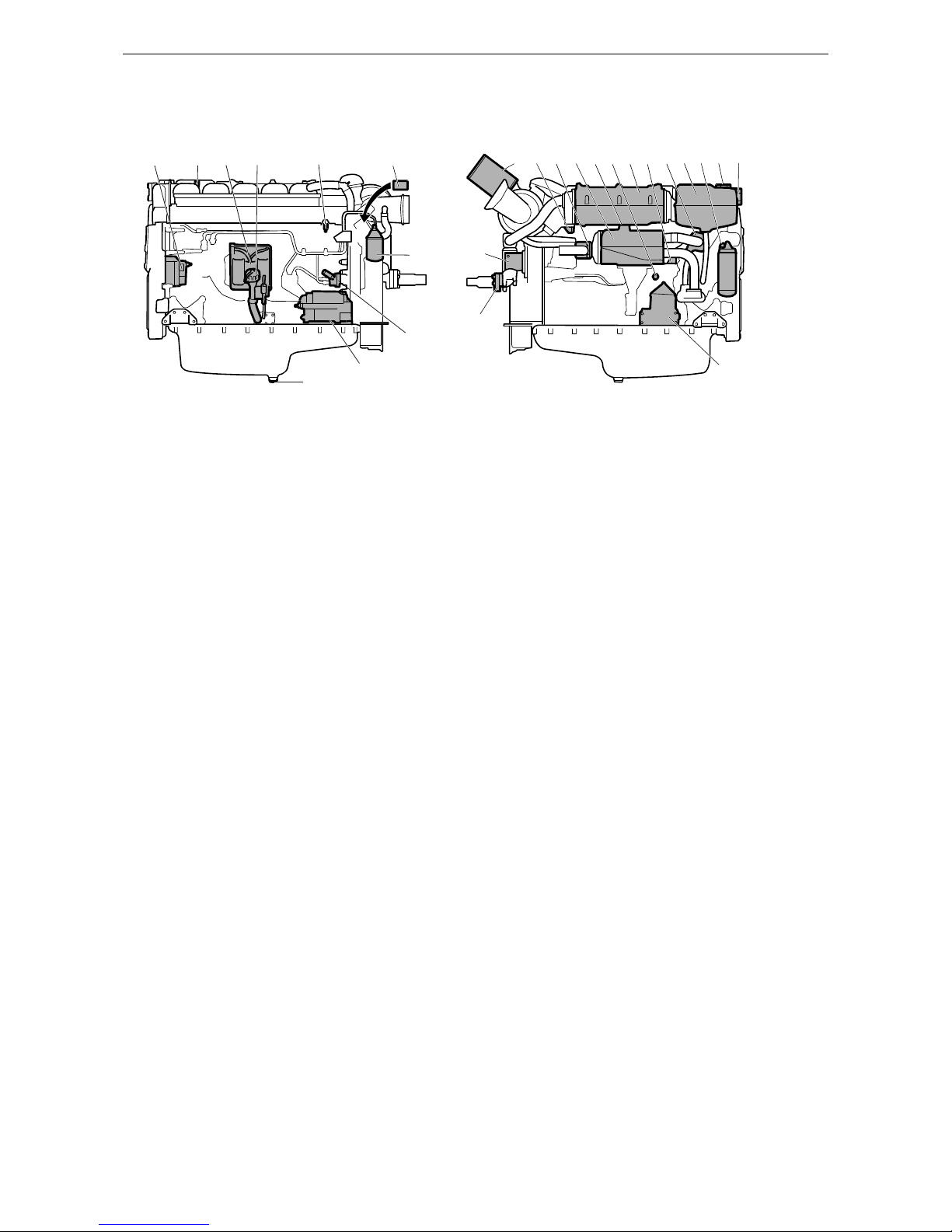
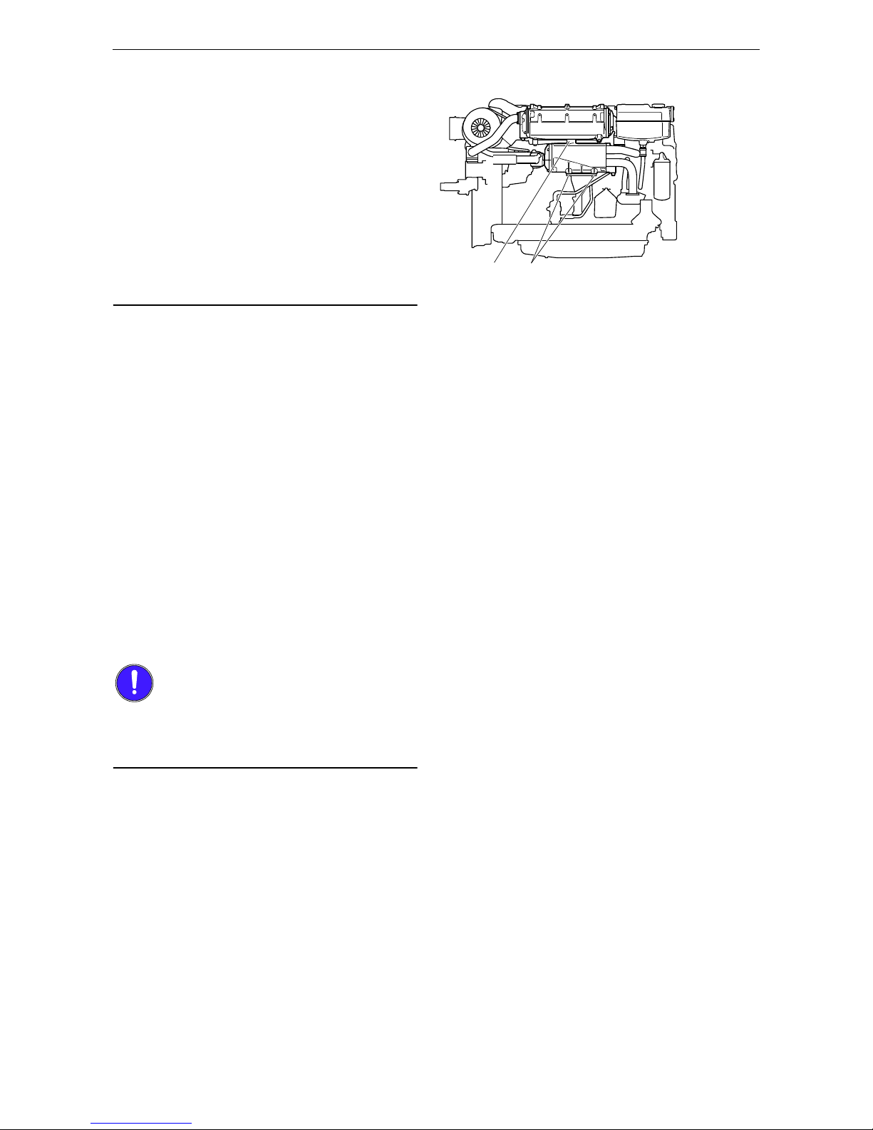
Component identification
1. Alternator
2. Oil filler cap
3. Engine control unit
4. Oil dipstick
5. Fuel manifold bleed nipple
6. Engine data plate
7. Fuel filter
8. Fuel pump with hand pump
9. Starter motor
10. Oil plug
11. Air filter
12. Sacrificial anodes (2)
13. Sea water outlet
14. Heat exchanger
15. Holes for draining condensation in charge air cooler
16. Coolant drain tap
17. Charge air cooler
18. Thermostat
19. Expansion tank
20. Oil filter
21. Filling coolant
22. Level glass for checking coolant level
23. Centrifugal oil cleaner
24. Sea water intake
25. Sea water pump
1
5
6
12
11
7
8
10
9
2
13
14
25
24
23
15 161712
18
19 20
21
22
3
4
343 190
The illustration shows a normal version of a DI13 engine with heat exchanger. The engine ordered may have
different equipment
Page 19

OPM 250 en-GB 19
©
Scania CV AB 2016, Sweden
Starting and running
Starting and running
Note:
When the engine is started for the first time, carry out the inspection points listed under First
start-up in the inspection schedule. See the Inspection section.
Always check the following before running:
• oil level
•coolant
• fuel level
• electrolyte level in batteries
• state of charge of the batteries
• condition of the drive belt.
Checks before running
Carry out a daily inspection as described in the
inspection schedule prior to operation. See the
Inspection section.
WARNING!
Block the starting device when working on the
engine. If the engine starts unexpectedly, there is
a serious risk of injury.
Page 20

OPM 250 en-GB 20
©
Scania CV AB 2016, Sweden
Starting and running
Starting the engine
For environmental reasons the Scania engine has
been developed to be started with a low fuel feed.
Using unnecessarily large amounts of fuel when
starting the engine always results in emissions of
unburnt fuel.
• Open the fuel cock if fitted.
• Disengage the engine.
• If the engine has a battery master switch:
Switch on the power by means of the battery
master switch.
• Start the engine.
If the fuel tank has been run dry or if the engine
has not been used for a long time, bleed the fuel
system.
WARNING!
Never use starter gas or similar agents to help
start the engine. An explosion may occur in the
intake manifold with a risk of personal injury.
Only start the engine in a well ventilated area.
When the engine is run in an enclosed space,
there must be effective devices to extract exhaust
gases and crankcase gases.
IMPORTANT!
The starter motor must only be cranked twice for
30 seconds at a time. After that, it must rest for at
least 5 minutes before the next attempt to start it.
Starting at low temperatures
Take the local environmental requirements into
account. Use a fuel heater and engine heater to
avoid starting problems and white smoke.
Scania recommends that an engine heater should
be used if the engine will be used at temperatures
below -10°C.
A low engine speed and a moderate load on a
cold engine limits white smoke, gives better
combustion and warms up the engine more
quickly than warming it up with no load.
Avoid running it longer than necessary at idling
speed.
Page 21

OPM 250 en-GB 21
©
Scania CV AB 2016, Sweden
Starting and running
Running
Check instruments and warning lamps at regular
intervals.
Engine speed range
Limp home mode
If there is a fault in the normal throttle opening or
if CAN communication is interrupted, the following emergency operation option is provided:
A CAN fault or throttle opening fault in an allspeed engine (both signal and idling switch):
• The throttle opening value is 0% and the engine is running at normal idling speed.
• The throttle opening value is 0% and the engine is running at raised idling speed (750
rpm) if this function is activated.
Throttle opening fault, but the idling switch is
working:
• The throttle opening value can be increased
slowly between 0 and 50% by using the idling
switch.
CAN fault:
• The engine is switched off if the shutdown
function is activated.
600-750 rpm Low idling. Engine idling is controlled by the engine manage-
ment system.
Low idling up to 2,300 rpm The engine operating speed range, depending on power class.
2,300-2,600 rpm Unsuitable operating speed, but a slightly higher engine speed
than the normal maximum operating speed may occur when
load is low or negative.
2,600-3,000 rpm Prohibited engine speed.
Page 22

OPM 250 en-GB 22
©
Scania CV AB 2016, Sweden
Starting and running
Coolant temperature
Normal coolant temperature during operation is
90-95°C/194–203°F for engines with a heat exchanger and 83-88°C/181-190°F for engines
with keel cooling.
Alarm levels are set in the engine control unit.
The default setting for the lowest and highest
limit values for high coolant temperature are
95°C/203°F and 105°C/221°F respectively.
The high coolant temperature alarm has the following functions:
• Alarm only.
• Alarm and torque reduction at the lowest limit value.
• Alarm at the lowest limit value and engine
shutdown at the highest limit value.
• Alarm, torque reduction at the lowest limit
value and engine shutdown at the highest limit value.
• Alarm at the lowest limit value and engine
shutdown at the highest limit value with the
possibility of engine shutdown override control.
• Alarm, torque reduction at the lowest limit
value and engine shutdown at the highest limit value, with the possibility of engine shutdown override control.
If run for extended periods under an extremely
light load, the engine may have difficulty in
maintaining the coolant temperature. At an increased load the coolant temperature rises to the
normal value.
IMPORTANT!
An excessively high coolant temperature can
damage the engine.
Page 23

OPM 250 en-GB 23
©
Scania CV AB 2016, Sweden
Starting and running
Oil pressure
Information about the normal oil pressure and
lowest permitted oil pressure is contained in the
section headed Technical Data.
The engine management system has the following alarm levels:
• At an engine speed below 1,000 rpm and an
oil pressure below 0.7 bar/10.2 psi.
• At an engine speed above 1,000 rpm and an
oil pressure below 2.5 bar/36.3 psi for longer
than 3 seconds.
The incorrect oil pressure alarm has the following functions:
• Alarm only.
• Alarm and torque reduction by 30%.
• Alarm and engine shutdown.
• Alarm and engine shutdown override control.
Note:
High oil pressure (above 6 bar/87 psi) is normal
when starting a cold engine.
Charging indicator lamp
If the lamp comes on during operation:
• Check and adjust the alternator drive belts as
described under the corresponding inspection
point. See the Inspection section.
If the charging indicator lamp is still on, this
could be due to an alternator fault or a fault in the
electrical system.
Belt transmission
When the belt transmission is new, it may make
a squeaking noise when running. The noise is
normal and disappears after 50-100 hours of operation.
The noise does not affect the service life of the
belt transmission.
Page 24

OPM 250 en-GB 24
©
Scania CV AB 2016, Sweden
Starting and running
Engine shutdown
1. Run the engine without a load for a few min-
utes if it has been run continuously with a
heavy load.
2. Switch off the engine.
Note:
The battery voltage must remain on for a few
seconds after the 15 voltage is switched off so
that the control units can store the values and
switch to standby mode.
10 prohibited engine shutdowns will cause a
torque reduction (70% of fuel quantity). Reset
the engine by switching it off correctly once.
IMPORTANT!
There is risk of post boiling and of damage to the
turbocharger if the engine is switched off without cooling.
The power must not be switched off before the
engine has stopped.
Page 25

OPM 250 en-GB 25
©
Scania CV AB 2016, Sweden
Starting and running
Checks after running
WARNING!
Block the starting device when working on the
engine. If the engine starts unexpectedly, there is
a serious risk of injury.
There is always a risk of sustaining burns when
an engine is hot. Particularly hot parts are turbochargers, oil sumps, hot coolant and oil in pipes
and hoses.
• Check that the power supply has been cut.
• Fill the fuel tank. Make sure that the filler cap
and the area round the filler opening are clean
to avoid contamination of the fuel.
• If there is a risk of freezing, the cooling system must contain enough glycol.
• If the temperature is below 0°C/32°F: Prepare
for the next start by connecting the engine
heater (if fitted).
IMPORTANT!
Check the coolant level following the first start.
Top up if necessary.
Page 26

OPM 250 en-GB 26
©
Scania CV AB 2016, Sweden
Inspection
Inspection
The inspection programme covers a number of
points that are divided into the following sections:
• Lubrication system
• Cooling system
• Air cleaner
• Miscellaneous
WARNING!
Block the starting device when working on the
engine. If the engine starts unexpectedly, there is
a serious risk of injury.
The inspection programme includes the following inspections:
• S inspection: Minimum basic inspection.
• M inspection: More extensive inspection.
• L inspection: Includes nearly all inspection
points.
• XL inspection: Includes all inspection points.
During a period, the sequence is S-M-S-L-S-MS-L-S-M-S-XL.
XL
6000
S
5500
M
5000
S
4500
L
4000
S
3500
M
3000
S
2500
L
2000
S
1500
M
1000
S
500
313 153
Page 27

OPM 250 en-GB 27
©
Scania CV AB 2016, Sweden
Inspection
Engines with few hours of operation
IMPORTANT!
On engines with few hours of operation, inspection must be carried out annually or every 5
years.
Stand-by generator sets and the like that are not
used regularly should be test run and checked in
accordance with the manufacturer's instructions.
The following inspection points must be carried
out once the engine has been warmed up to operating temperature.
1. Checking oil level.
2. Checking coolant level.
3. Checking vacuum indicator.
4. Checking fuel level.
5. Check for engine leaks.
Page 28

OPM 250 en-GB 28
©
Scania CV AB 2016, Sweden
Inspection
Inspection interval
1 More often if required.
Daily First time at Interval (hours) At least
first start 500 500 1,000 2,000 6,000 annu-
ally
every
5
years
SMLXL
Lubrication system
XX
Checking oil level
Changing the oil
X
1
X
1
X 1X
1
X
Cleaning the centrifugal oil
cleaner
X
1
X
1
X 1X
1
X
Renewing the oil filter
X
1
X
1
X 1X
1
X
Cooling system
X
Checking coolant level
Checking sacrificial anodes XXXXX
Checking the sea water pump
impeller
XX X X X
Checking coolant antifreeze or
corrosion protection
X
X
XX
Cleaning the cooling system and
changing coolant
XX
Air cleaner
X
Reading the vacuum indicator
Renewing the filter element
X
1
XX
Renewing the safety cartridge XX X
Fuel system
XX
Checking the fuel level
Renewing the fuel filter
X
1
X
1
X
1
X
Miscellaneous
XXXXX
Checking the drive belt
Checking for leaks XXX
Checking and adjusting valve
clearances and injectors
XXX
Page 29

OPM 250 en-GB 29
©
Scania CV AB 2016, Sweden
Lubrication system
Lubrication system
Oil grade
Scania LDF stands for the Scania Long Drain
Field test standard. Scania LDF oils have been
carefully selected after extensive testing. The approval is only granted to the highest quality engine oils available on the market.
The engine oil must fulfil the following quality
requirements:
• ACEA E5/API CI-4
• ACEA E7/API CI-4+
• For engines not run on low-sulphur fuel, the
TBN (Total Base Number) should be at least
12 (ASTM 2 896).
• Oils with a low ash content (ACEA E9/API
CJ4) are not recommended.
Check with your oil supplier that the oil meets
these requirements.
If the engine is used in areas of the world where
lubricating oil with ACEA or API classification
is not available, the oil grade must be measured
in actual operation. In this case contact the nearest Scania workshop.
For operation at extremely low outdoor temperatures: Consult your nearest Scania representative
on how to avoid starting difficulties.
Recommended oil
Scania Oil LDF
Scania Oil LDF-2
Scania Oil LDF-3
Scania Oil E7
Viscosity class Outdoor temperature
SAE 20W-30 -15°C (5°F) - +30°C (86°F)
SAE 30 -10°C (14°F) - +30°C (86°F)
SAE 40 -5°C (23°F) - > +45°C (113°F)
SAE 50 0°C (32°F) - > +45°C (113°F)
SAE 5W-30 < -40°C (-40°F) - +30°C (86°F)
SAE 10W-30 -25°C (-13°F) - +30°C (86°F)
SAE 15W-40 -20°C (-4°F) - > +45°C (113°F)
Page 30

OPM 250 en-GB 30
©
Scania CV AB 2016, Sweden
Lubrication system
Oil analysis
To be able to extend the oil change intervals using an oil analysis, Scania LDF-2 and LDF-3 oils
must be used.
Oil companies can offer analysis of the engine
oil.
The following conditions must remain fulfilled
when the oil is changed.
• Viscosity at 100°C (212°F): max. ±20% of
original value of the fresh oil.
• TBN (in accordance with ASTM D4739): >
3.5
• TBN (in accordance with ASTM D4739): >
TAN (in accordance with ASTM D664)
• Soot (DIN 51452): < 3%
Such analysis measures the oil's TBN (Total
Base Number), TAN (Total Acid Number), fuel
dilution, water content, viscosity and the quantity of particles and soot in the oil.
The result of a series of analyses is used as the
basis for establishing a suitable oil change interval.
If the conditions are changed, a new oil analysis
programme must be carried out to establish new
change intervals.
Checking oil level
Checking the oil level with the engine
switched off
Note:
Leave the engine off for at least 1 minute before
checking the oil level.
1. Remove the oil dipstick (1) and check the oil
level. The correct level is between the minimum and maximum marks on the oil dipstick.
2. Top up with more oil (2) when the oil level is
at or below the lower mark.
Information on the correct oil type is found under
the heading Oil grade.
312 506
2
1
Page 31

OPM 250 en-GB 31
©
Scania CV AB 2016, Sweden
Lubrication system
Changing the oil
Note:
Renew the oil filter and clean the centrifugal oil
cleaner when changing oil.
WARNING!
Hot oil can cause burns and skin irritation. Wear
protective gloves and goggles when changing
hot oil.
Make sure that there is no pressure in the lubrication system before starting work on it.
The oil filler cap must always be in place when
starting and running the engine to prevent oil being ejected.
Environment
Use a container to avoid spillage. Used oil must
be disposed of as specified in national and international law.
Note:
Change oil more often if the engine is subjected
to particularly demanding operation, such as a
dusty environment, or if deposits in the centrifugal oil cleaner are thicker than 28 mm (1.1 in).
1. Unscrew the oil plug and drain the oil when
the engine is hot.
In certain engines the oil is pumped out by
means of a bilge pump.
2. Clean the magnet on the oil plug.
3. Refit the oil plug.
4. Top up with oil.
5. Check the level on the oil dipstick.
314 603
Min. 40 litres (10.5 US gallons)
Max. 48 litres (12.6 US gallons)
314 602
Max. 34 litres (9 US gallons)
Min. 28 litres (7.4 US gallons)
325 168
Max. 30 litres (7.9 US gallons)
Min. 25 litres (6.6 US gallons)
Page 32

OPM 250 en-GB 32
©
Scania CV AB 2016, Sweden
Lubrication system
Maximum angles of inclination during operation
Maximum permissible angles during operation
vary, depending on the type of oil sump; see illustration.
Renewing the oil filter
IMPORTANT!
Clean the centrifugal oil cleaner when renewing
the oil filter. Otherwise, the oil filter will be
blocked and resistance in the filter will increase.
If this happens, an overflow valve in the filter retainer opens and lets the oil pass without being
filtered.
1. Remove the old filter.
2. Oil the rubber gasket on the new filter.
3. Tighten the filter by hand. Never use tools,
the filter could sustain damage, obstructing
circulation.
4. Start the engine and check for leaks.
30°
30°
30° 30°
30°
25°
25°
30°
30°
25°
25°
30°
343 842
325 164
Page 33
OPM 250 en-GB 33
©
Scania CV AB 2016, Sweden
Lubrication system
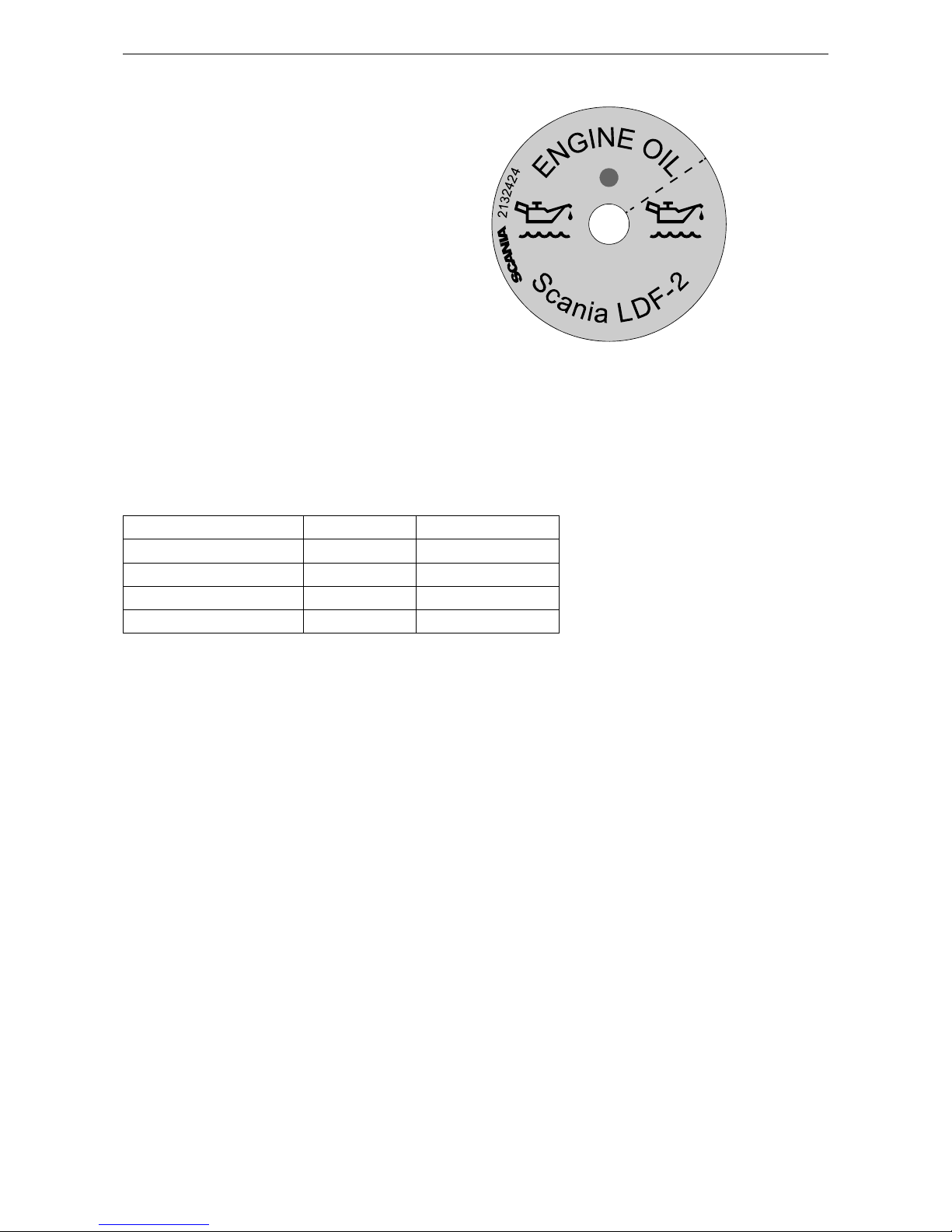
Labels for top-up engine oil
grade
When changing oil it is important to use the correct engine oil grade.
The oil filler cap must be clearly marked with a
label showing the top-up oil grade.
If the label is missing or if the engine oil grade is
changed, a new label must be fitted.
Parts
Oil grade Colour Part No.
Scania LDF-2 Blue 2 132 424
Scania LDF-3 Red 2 132 426
Scania LDF Grey 2 269 345
ACEA E7 White 2 132 425
336 492
The illustration shows the label for oil grade Scania
LDF-2.
Page 34

OPM 250 en-GB 34
©
Scania CV AB 2016, Sweden
Lubrication system
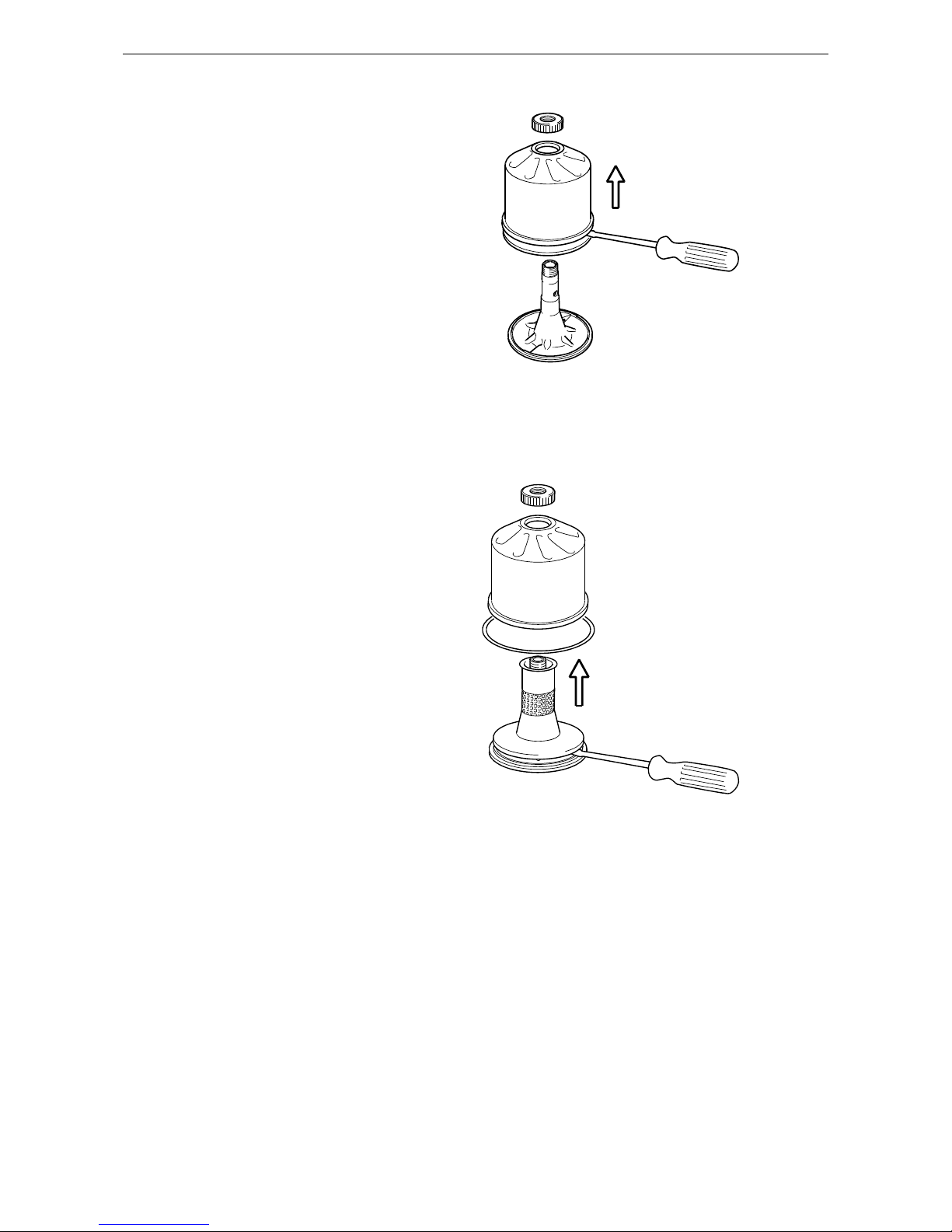
Cleaning the centrifugal oil
cleaner
When cleaning the centrifugal oil cleaner there
will be some dirt deposits in the rotor cover. If
this is the case, this indicates that the rotor is
working. If it is not working, the cause must be
established immediately.
If the dirt deposit exceeds 28 mm at the recommended intervals, the rotor cover should be
cleaned more often.
WARNING!
The oil may be hot. Carefully remove the cover
from the centrifugal oil cleaner.
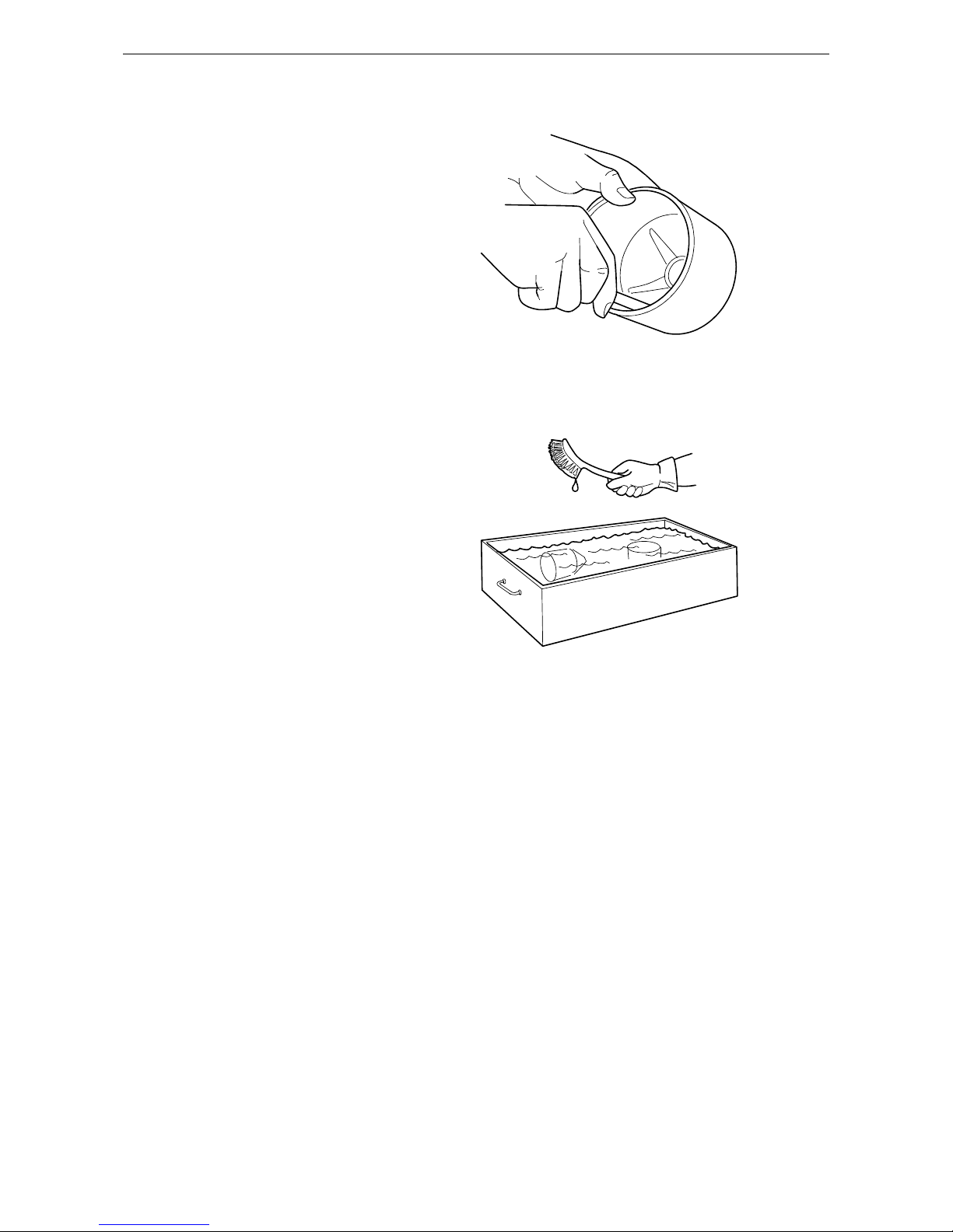
1. Clean the cover. Unscrew the nut securing
the outer cover.
2. Let the oil run out from the rotor.
3. Lift out the rotor. Wipe off the outside. Undo
the rotor nut and unscrew it about 1.5 turns to
protect the bearing.
Note:
Take care not to damage the rotor shaft.
4. If the rotor nut is difficult to get loose, turn
the rotor upside down and fasten the rotor nut
in a vice. Turn the rotor counterclockwise
1.5 turns by hand or use an M20 nut, see illustration.
IMPORTANT!
The rotor must not be put in a vice. Never strike
the rotor cover. This may cause damage resulting
in imbalance.
x 1.5
133 315
x 1.5
M20
133 316
Page 35
OPM 250 en-GB 35
©
Scania CV AB 2016, Sweden
Lubrication system
5.
Remove the rotor cover by holding the rotor
in both hands and tapping the rotor nut
against the table. Never strike the rotor directly as this may damage its bearings.
6. Remove the strainer from the rotor cover. If
the strainer is stuck, insert a screwdriver between the rotor cover and strainer and carefully prise them apart.
133 317
127 878
Page 36
OPM 250 en-GB 36
©
Scania CV AB 2016, Sweden
Lubrication system
7.
Remove the paper insert and scrape away
any remaining dirt deposits inside the rotor
cover. If the deposits are thicker than 28 mm,
the centrifugal oil cleaner must be cleaned
more often.
8. Wash the parts.
9. Inspect the 2 nozzles on the rotor. Ensure that
they are not blocked or damaged. Renew any
damaged nozzles.
10. Check that the bearings are undamaged.
333 044
333 037
Page 37

OPM 250 en-GB 37
©
Scania CV AB 2016, Sweden
Lubrication system
11.
Fit a new paper insert on the inside of the rotor cover. Fit the strainer onto the rotor.
12. Fit the strainer onto the rotor.
13. Fit a new O-ring by sliding it over the strain-
er.
14. Refit the rotor cover. Make sure that the O-
ring is seated correctly on the inside.
15. Screw the rotor nut back on by hand.
16. Check that the shaft is not loose. Secure with
thread-locking fluid 561 200 if it is loose.
First clean thoroughly using a suitable solvent. Tighten the rotor shaft using socket
wrench 99 520. Tightening torque 27 Nm.
Note:
Take care not to damage the rotor shaft.
1
234
337 178
127 881
Page 38

OPM 250 en-GB 38
©
Scania CV AB 2016, Sweden
Lubrication system
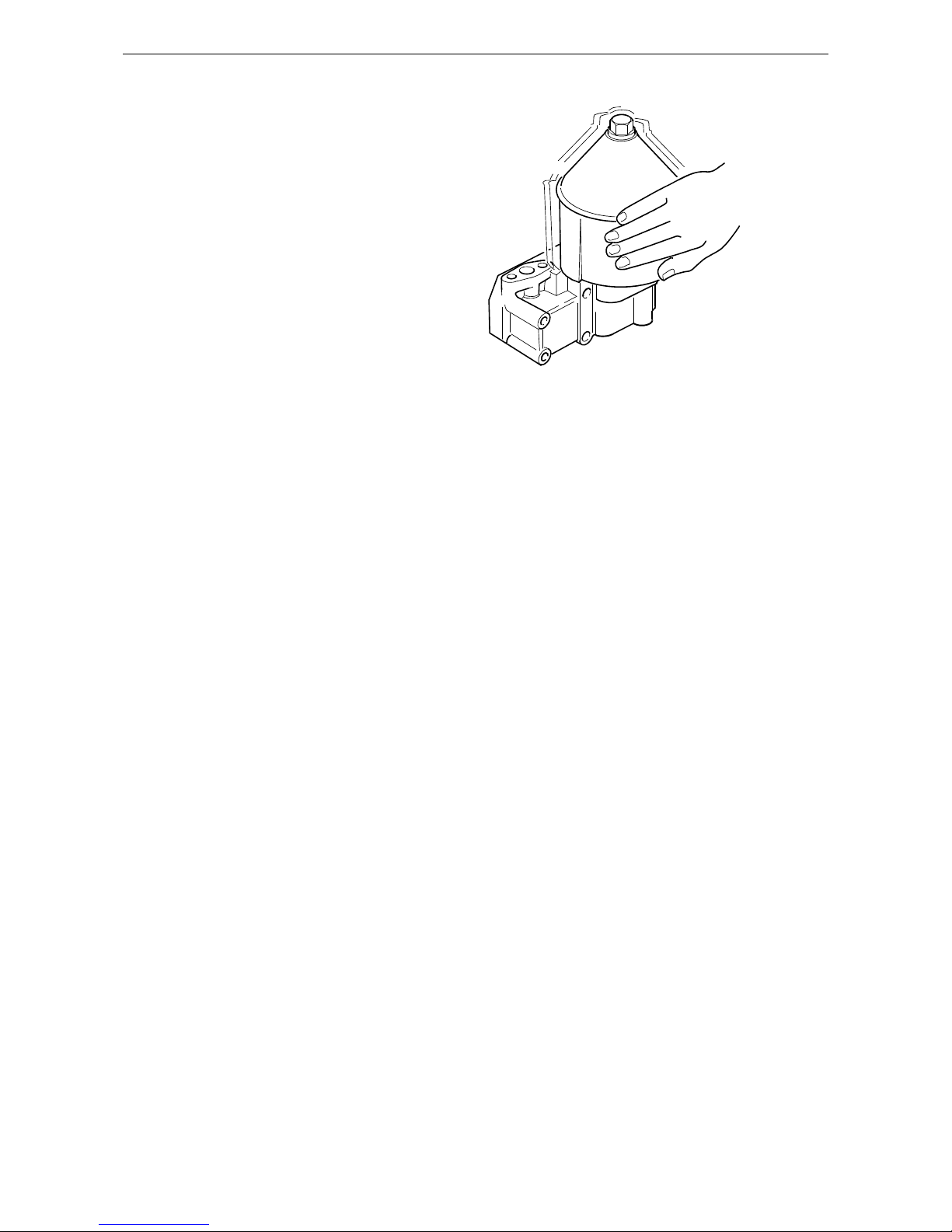
17.
Refit the rotor and rotate it by hand to make
sure it rotates easily.
18. Renew the O-ring on the cover of the oil
cleaner housing and fit the cover. Tighten the
lock nut to 15 Nm.
127 882
127 883
15 Nm
Page 39
OPM 250 en-GB 39
©
Scania CV AB 2016, Sweden
Lubrication system
Operational testing
Operational testing need only be carried out if it
is suspected that the centrifugal oil cleaner is not
working properly. For example, if there is an abnormally small amount of deposit in the centrifugal oil cleaner in relation to the distance driven.
The rotor rotates very fast and should continue to
turn when the engine has stopped.
1. Run the engine until it is warm.
2. Stop the engine and listen for noise coming
from the rotor. Use your hand to feel if the
filter housing is vibrating.
3. If the filter housing is not vibrating, disman-
tle and check the centrifugal oil cleaner.
333 039
Page 40

OPM 250 en-GB 40
©
Scania CV AB 2016, Sweden
Cooling system
Cooling system
Coolant
WARNING!
Ethylene glycol can be fatal if ingested and can
cause skin irritation and eye damage.
The coolant recommended by Scania is a mixture of water with antifreeze and corrosion inhibitor (ethylene glycol). The coolant has several
characteristics which are important for the operation of the cooling system:
• Corrosion inhibitor
• Antifreeze
• Increases the boiling point
The coolant should always contain 35-55% by
volume of antifreeze and corrosion inhibitor so
that the coolant properties ensure that the coolant
works correctly.
Note:
The coolant should be changed when the cooling
system is cleaned: every 6,000 hours or at least
every 5 years. Refer to Changing coolant.
Coolant resistance to cold
The following example shows coolant properties
with 30 percent by volume of antifreeze and corrosion inhibitor:
• Ice slush starts to form at -16°C (3°F).
• At -30°C (-22°F), there is a risk of cooling
system malfunction.
• There is no risk of damage by freezing with a
minimum antifreeze and corrosion inhibitor
content of 35 percent by volume.
The chart depicts coolant properties at different
percents of antifreeze and corrosion inhibitor
concentration by volume.
Curve A: Ice formation starts (ice slush)
Curve B: Damage by freezing occurs
Area 1: Safe area
Area 2: Malfunctions may occur (ice
slush)
312 505
2
1
3
°C
BA
-50
-40
-30
-20
-16
-10
0
10020 30 40 50
%
Page 41

OPM 250 en-GB 41
©
Scania CV AB 2016, Sweden
Cooling system
Area 3: Risk of damage by freezing
Page 42

OPM 250 en-GB 42
©
Scania CV AB 2016, Sweden
Cooling system
Antifreeze and corrosion inhibitor concentration table
35% by volume of Scania antifreeze provides
sufficient protection against corrosion.
Example:
1. The total volume of the cooling system is 40
litres in this example.
2. The measured concentration of ethylene gly-
col is 35% by volume (freezing point -21
°C). According to the table there are 14 litres
of ethylene glycol in the cooling system.
3. The required concentration of ethylene gly-
col is 45% by volume (freezing point -30
°C). According to the table, 18 litres of ethylene glycol are required in the cooling system.
4. Since there are already 14 litres in the cool-
ing system, 4 litres of ethylene glycol must
be added to the cooling system (18 - 14 = 4
litres).
For calculation Adequate protection against corrosion
Volume of ethylene glycol
(%) 202530 3540455060
Cooling system
volume (litres)
Ice slush forms (°C) -6 -9 -12 -21 -24 -30 -38 -50
Volume of ethylene glycol (litres)
5 6 8 1112141518 30
6 8 10 14 16 18 20 24 40
8 1013 1820232530 50
9 1215 2124273036 60
11 14 18 25 28 32 35 42 70
12 16 20 28 32 36 40 48 80
14 18 23 32 36 41 45 54 90
15 20 25 35 40 45 50 60 100
17 22 28 39 44 50 55 66 110
18 24 30 42 48 54 60 72 120
20 26 33 46 52 59 65 78 130
21 28 35 49 56 63 70 84 140
23 30 38 53 60 68 75 90 150
24 32 40 56 64 72 80 96 160
26 34 43 60 68 77 85 102 170
27 36 45 63 72 81 90 108 180
29 38 48 67 76 86 95 114 190
30 40 50 70 80 90 100 120 200
Page 43

OPM 250 en-GB 43
©
Scania CV AB 2016, Sweden
Cooling system
Antifreeze and corrosion inhibitor concentration table
35% by volume of Scania antifreeze provides
sufficient protection against corrosion.
Example:
1. The total volume of the cooling system is
10.6 US gallons in this example.
2. The measured concentration of ethylene gly-
col is 35% by volume (freezing point -6°F).
According to the table there are 3.7 US gallons of ethylene glycol in the cooling system.
3. The required concentration of ethylene gly-
col is 45% by volume (freezing point -22°F).
According to the table, 4.8 US gallons of ethylene glycol are required in the cooling system.
4. Since the cooling system already contains
3.7 US gallons, fill another 1.1 US gallons of
ethylene glycol in the cooling system (4.8 -
3.7 = 1.1 US gallons).
For calculation Adequate protection against corrosion
Volume of ethylene glycol
(%) 202530 3540455060
Cooling system
volume (US gallons)
Ice slush forms (°F) 21 16 10 -6 -11 -22 -36 -58
Volume of ethylene glycol
(US gallons)
1.3 1.6 2.1 2.9 3.2 3.7 4 4.8 7.9
1.6 2.1 2.6 3.7 4.2 4.8 5.3 6.3 10.6
2.1 2.6 3.4 4.8 5.3 6.1 6.6 7.9 13.2
2.4 3.2 4 5.5 6.3 7.1 7.9 9.5 15.9
2.9 3.7 4.8 6.6 7.4 8.5 9.2 11.1 18.5
3.2 4.2 5.3 7.4 8.5 9.5 10.6 12.7 21.1
3.7 4.8 6.1 8.5 9.5 10.8 11.9 14.3 23.8
4 5.3 6.6 9.2 10.6 11.9 13.2 15.9 26.4
4.5 5.8 7.4 10.3 11.6 13.2 14.5 17.4 29.1
4.8 6.3 7.9 11.1 12.7 14.3 15.9 19 31.7
5.3 6.9 8.7 12.2 13.7 15.6 17.2 20.6 34.3
5.5 7.4 9.2 12.9 14.8 16.6 18.5 22.2 37
6.1 7.9 10 14 15.9 18 19.8 23.8 39.6
6.3 8.5 10.6 14.8 16.9 19 21.1 25.4 42.3
6.9 9 11.4 15.9 18 20.3 22.5 26.9 44.9
7.1 9.5 11.9 16.6 19 21.4 23.8 28.5 47.6
7.7 10 12.7 17.7 20.1 22.7 25.1 30.1 50.2
7.9 10.6 13.2 18.5 21.1 23.8 26.4 31.7 52.8
Page 44

OPM 250 en-GB 44
©
Scania CV AB 2016, Sweden
Cooling system
Checking coolant level
The following instructions apply to Scania expansion tanks. For other types of expansion
tanks, follow the manufacturer's instructions.
WARNING!
Never open the coolant filler cap when the engine is hot. Hot coolant and steam may spray out
and cause burns.
If the cap has to be opened do it slowly and carefully to release the pressure before removing the
cap. Wear gloves as the coolant is still very hot.
1. Check the coolant level through the sight
glass.
2. Top up with coolant as necessary.
IMPORTANT!
Do not top up large quantities of coolant through
the expansion tank. Top up in accordance with
the instructions in the section headed Changing
coolant instead.
Never fill a large amount of cold coolant in a hot
engine. There is great risk of cracks forming in
the cylinder block and cylinder heads.
Only pour pre-mixed coolant into the cooling
system.
Page 45

OPM 250 en-GB 45
©
Scania CV AB 2016, Sweden
Cooling system
Checking the sacrificial anodes
• Empty the sea water circuit and check the sacrificial anodes.
• Scrape off all loose material from the anode.
• Renew if less than half the anode is left. A
new anode is 60 mm long with a diameter of
17 mm.
• If the sacrificial anodes are very corroded, the
inspection interval must be reduced
Checking the sea water pump
impeller
• Close the bottom valve if the sea water pump
is below water level.
• Drain the sea water circuit.
• Take off the sea water pump cap.
• Check that the vanes of the impeller are not
heavily splintered or damaged.
Note:
If the impeller must be renewed frequently, the
cleaning of the sea water must be improved.
Renewing the impeller
• Pull out the impeller using puller 98 482.
• Fit a new impeller and cap. Check that the cap
seal is not hard or damaged.
Note:
There should be a spare impeller on board.
The impeller can be deformed during extended
periods of inactivity. Renew the impeller before
starting or remove the impeller before longer periods of stoppage. See also "Preparations for
storage".
325 163
325 165
Page 46

OPM 250 en-GB 46
©
Scania CV AB 2016, Sweden
Cooling system
Checking antifreeze and corrosion inhibitor
Note:
Use only pure fresh water that is free from particles, sludge and other impurities.
1. Pour a small amount of coolant into a con-
tainer and check that the coolant is pure and
clear.
2. Change the coolant if it is contaminated or
cloudy.
3. Measure the antifreeze content with one of
the following instruments:
The following rules apply to ethylene glycolbased coolant:
• The antifreeze and corrosion inhibitor content
must be minimum 35 percent by volume for
corrosion protection to be sufficient.
• An antifreeze and corrosion inhibitor content
greater than 55 percent by volume impairs the
ability to protect against frost.
• If ice forms in the coolant, there are disruptions initially, but there is no immediate risk
of damage. The engine should not be subjected to heavy loads when ice starts to form.
Part No. Designation
588 805 Refractometer
588 226 Refractometer
Page 47

OPM 250 en-GB 47
©
Scania CV AB 2016, Sweden
Cooling system
Antifreeze and corrosion inhibitor
Only the product Scania coolant, or other products that are tested to provide proper antifreeze
and protection against corrosion for Scania, may
be used in Scania engines. Products that do not
satisfy the requirements for use in a Scania engine can result in faults in and damage to the
cooling system. This can lead to the invalidation
of Scania's warranty for faults and damage
caused by the use of inappropriate coolant.
The antifreeze and corrosion inhibitor used in
Scania engines should be of the ethylene glycol
type.
Scania concentrate
Designation Contents Part No. Volume Volume (US
gallons)
Coolant Antifreeze and corrosion inhibitor (concentrate) 1 894 323 5 l 1.3 gallons
Coolant Antifreeze and corrosion inhibitor (concentrate) 1 894 324 20 l 5.3 gallons
Coolant Antifreeze and corrosion inhibitor (concentrate) 1 894 325 210 l 55 gallons
Coolant Antifreeze and corrosion inhibitor (concentrate) 1 894 326 1,000 l 264 gallons
Scania Ready Mix
Designation Contents Part No. Volume Volume (US
gallons)
Coolant Scania antifreeze and corrosion inhibitor Ready Mix
50/50
1 921 955 5 l 1.3 gallons
Coolant Scania antifreeze and corrosion inhibitor Ready Mix
50/50
1 921 956 20 l 5.3 gallons
Coolant Scania antifreeze and corrosion inhibitor Ready Mix
50/50
1 921 957 210 l 55 gallons
Coolant Scania antifreeze and corrosion inhibitor Ready Mix
50/50
1 896 695 1,000 l 264 gallons
Page 48

OPM 250 en-GB 48
©
Scania CV AB 2016, Sweden
Cooling system
Changing coolant
Environment
Avoid spillage and use a suitable container. Used
coolant must be disposed of as specified in national and international law.
Draining coolant
• Drain coolant from the engine by opening the
expansion tank filler cap. Detach the drain tap
located on the right-hand side below the heat
exchanger.
• It is also possible to drain the coolant from the
lowest point in the engine and the cooling
system.
Draining the sea water circuit
• Drain the sea water circuit by first closing the
sea cock of the vessel and then removing the
connection pipe from the heat exchanger outlet (1).
• Also remove the cover from the sea water
pump (2) to completely drain the pump.
325 364
2
1
325 342
Page 49

OPM 250 en-GB 49
©
Scania CV AB 2016, Sweden
Cooling system
Filling coolant
1. Connect the hose from unit 588 540 to the
engine's drain valve.
2. Open the expansion tank cap.
3. Pump in coolant using coolant unit 588 540.
Fill with coolant to the max. level of the expansion tank.
4. Disconnect the hose
5. Set the heating control to maximum heating
and start the engine. Idling speed must not
exceed 600 rpm. Leave the engine idling for
15 minutes.
6. Stop the engine and top up with coolant to
the maximum level through the expansion
tank.
7. Air pockets may still be left in the cooling
system, which will disappear after the engine
has been operated for a period of time. It
may, therefore, need some topping up to start
with.
IMPORTANT!
When it is necessary to fill a large quantity of
coolant, it must be pumped in from underneath.
This is to ensure that air does not get into the
cooling system, which can cause the coolant
pump to overheat.
307 399
Unit 588 540
Page 50
OPM 250 en-GB 50
©
Scania CV AB 2016, Sweden
Cooling system
Cleaning the cooling system
Note:
Clean the cooling system more often than the inspection interval if necessary.
IMPORTANT!
Do not use caustic soda or other alkaline detergent as this could damage the aluminium.
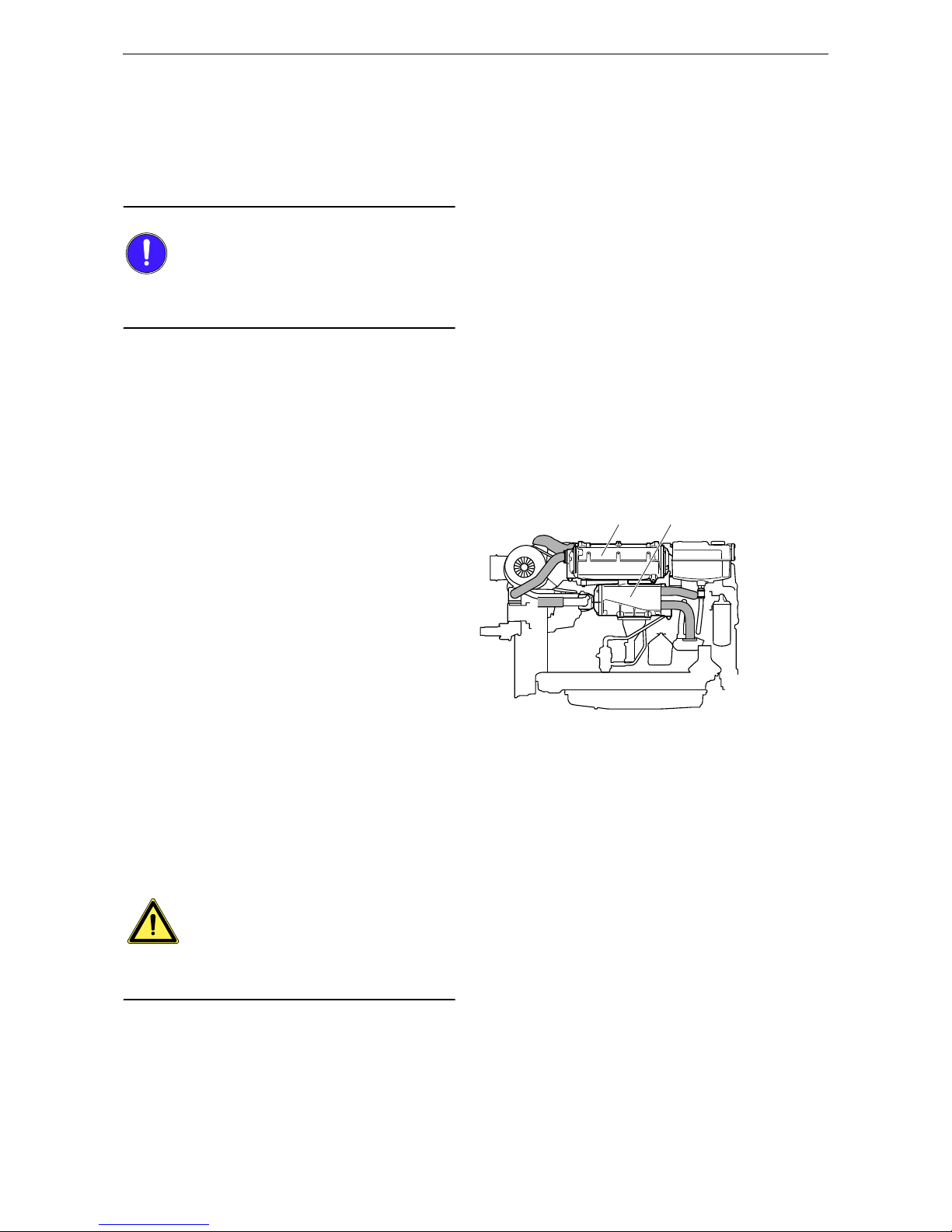
Removing heat exchanger and
charge air cooler
1. Make sure that the system is empty as de-
scribed earlier.
2. Remove the protective plate that sits on the
charge air cooler.
3. Detach the inlet pipe from the turbocharger.
4. Remove the front charge air pipe by loosen-
ing the screws on the bracket, protection cover and inlet pipe.
5. Remove the water pipe from the sea water
pump to the charge air cooler.
6. Detach the upper clamp on the rubber bel-
lows between the charge air cooler and the
heat exchanger.
7. Undo the screws securing the charge air
cooler to the engine.
8. Remove the charge air cooler and the brack-
et.
9. Remove the pipe between the heat exchanger
and the exhaust pipe.
10. Remove the coolant pipes, both intake and
outlet, from the heat exchanger.
11. Detach the heat exchanger from the bracket.
WARNING!
To ensure proper handling of cooling system detergent, study the warning text on the package.
A B
325 343
A Charge air cooler
B Heat exchanger
Page 51

OPM 250 en-GB 51
©
Scania CV AB 2016, Sweden
Cooling system
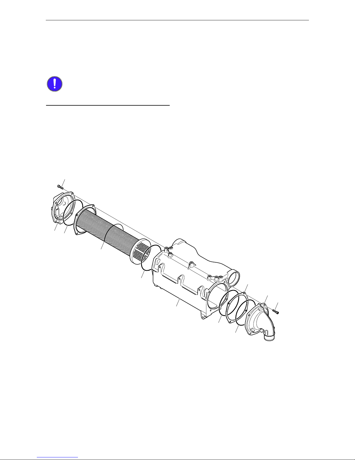
Cleaning the heat exchanger
1. Remove the cover and pull out the cooler
core.
2. Clean the outside of the cooler core.
IMPORTANT!
Use a paraffin-based engine cleaning agent.
3. Remove any internal deposits using a round
rod.
4. Replace damaged and hard O-rings.
5. Assemble the heat exchanger.
6. Tighten the screws to 15-18 Nm.
7. Fit the heat exchanger according to the de-
scription.
1. Screw
2. Rear cover
3. O-ring
4. Cooler core
5. Housing
6. Flange
7. Front cover
1
1
6
7
2
3
4
5
3
3
3
325 160
Page 52
OPM 250 en-GB 52
©
Scania CV AB 2016, Sweden
Cooling system
Cleaning the charge air cooler
1. Remove the charge air cooler cover and pull
out the cooler core.
2. Clean the outside of the cooler core.
IMPORTANT!
Use a paraffin-based engine cleaning agent.
3. Remove any internal deposits using a round
rod.
4. Renew damaged and hard O-rings and as-
semble the charge air cooler.
5. Tighten the screws to 15-18 Nm.
6. Fit the charge air cooler according to the de-
scription.
1. Screw
2. Rear cover
3. O-ring
4. Cooler core
5. Charge air cooler
6. Flange
7. Front cover
1
1
2
3
4
3
3
3
5
6
7
325 161
Page 53
OPM 250 en-GB 53
©
Scania CV AB 2016, Sweden
Cooling system
Fitting heat exchanger and charge air
cooler
1. Fit the heat exchanger on the bracket.
2. Fit the charge air cooler bracket and tighten
the screws as illustrated.
Note:
When the heat exchanger is re-fitted, the screw
(26 Nm) on the upper side must be fitted first.
Then fit the lower screws (50 Nm). Otherwise
there is a risk of serious damage.
Tightening torques for screws.
M6: 10 Nm
M8: 26 Nm
M10: 50 Nm
3. Fit the coolant pipes to the heat exchanger.
4. Fit the heat exchanger outlet pipe for sea wa-
ter.
5. Fit the charge air cooler, inlet pipe from the
turbocharger and the outlet pipe. Check Orings, apply vaseline and push the pipes into
position. Torque tighten the screws.
6. Fill the system with coolant according to
specification.
7. Start the engine and check that no leakage
occurs. Check the coolant level and top up as
necessary.
IMPORTANT!
Use silicone or teflon-based grease to lubricate
the O-rings. Only lubricate the O-rings, too
much grease can cause leakage.
1
2
325 344
Page 54

OPM 250 en-GB 54
©
Scania CV AB 2016, Sweden
Cooling system
Internal: Removing oil and grease
1. Run the engine until it has reached operating
temperature and then drain the cooling system.
2. Remove the thermostats.
3. Fill the system with clean, hot water mixed
with liquid dishwasher detergent intended
for household machines. Concentration 1%
(0.1/10 litres).
4. Warm up the engine for approximately 20-
30 minutes. Remember to switch on the cab
heating system, if one is installed.
5. Drain the cooling system.
6. Fill the system with clean, hot water and run
the engine for about 20-30 minutes.
7. Drain the water from the cooling system.
8. Refit the thermostats.
9. Fill the cooling system with new coolant fol-
lowing the specification under Coolants earlier in the document.
Environment
Avoid spillage and use a suitable container. Used
coolant must be disposed of as specified in national and international law.
Page 55

OPM 250 en-GB 55
©
Scania CV AB 2016, Sweden
Cooling system
Internal: Removing deposits
1. Run the engine until it has reached operating
temperature and then drain the cooling system.
2. Remove the thermostats.
3. Fill the system with clean, hot water mixed
with some commercially available radiator
detergent which is based on sulphamic acid
and contains dispersing agents. Follow the
manufacturer's instructions for the concentration and cleaning period.
4. Run the engine for the specified time. Re-
member to switch on the cab heating system,
if one is installed.
5. Drain the cooling system.
6. Fill the cooling system with clean, hot water
and run the engine for about 20-30 minutes.
7. Drain the water from the cooling system.
8. Refit the thermostats.
9. Fill the system with new coolant following
the specification under Coolants earlier in
the document.
Environment
Avoid spillage and use a suitable container. Used
coolant must be disposed of as specified in national and international law.
Page 56
OPM 250 en-GB 56
©
Scania CV AB 2016, Sweden
Air cleaner
Air cleaner
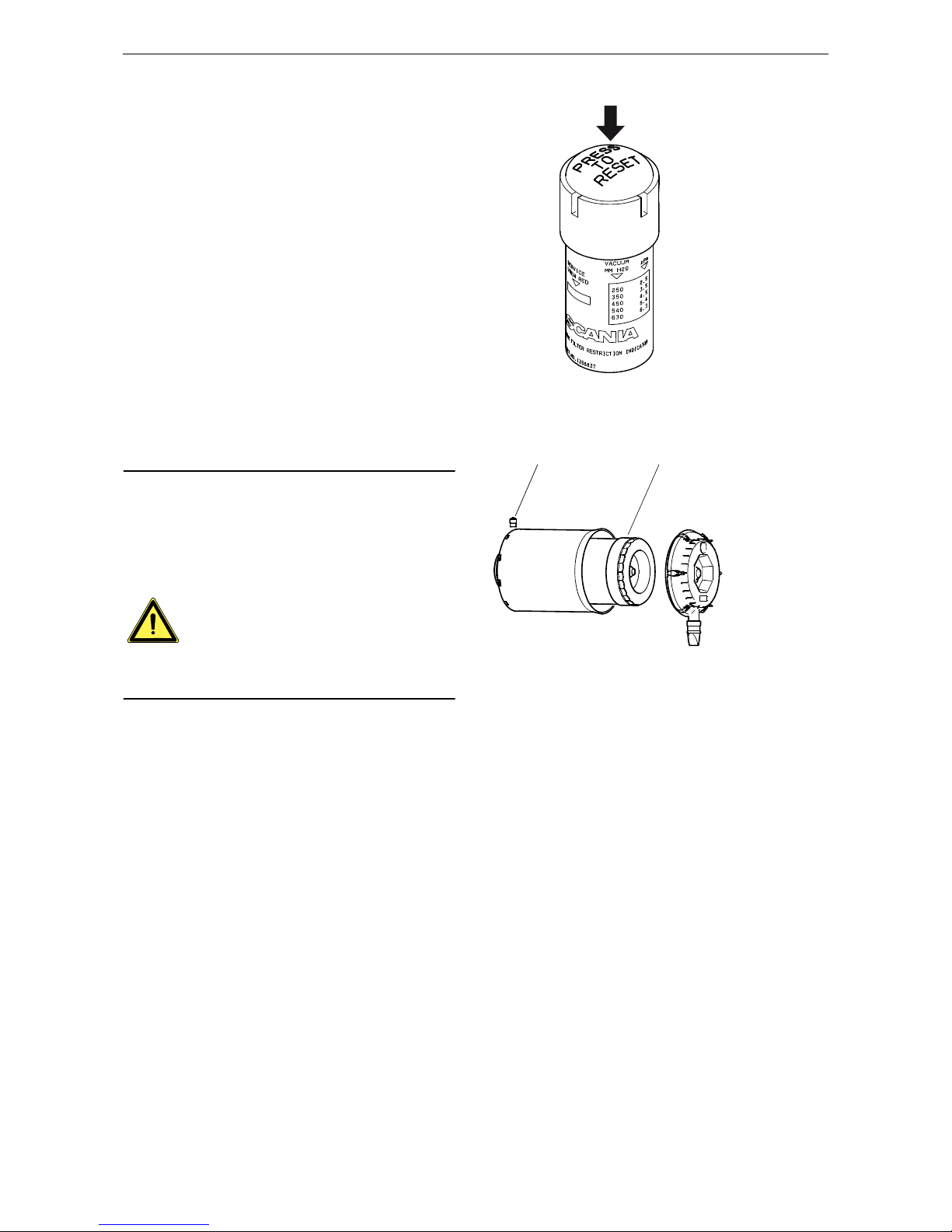
Reading the vacuum indicator
If the indicator's red plunger is fully visible, renew the air cleaner filter element following the
instructions.
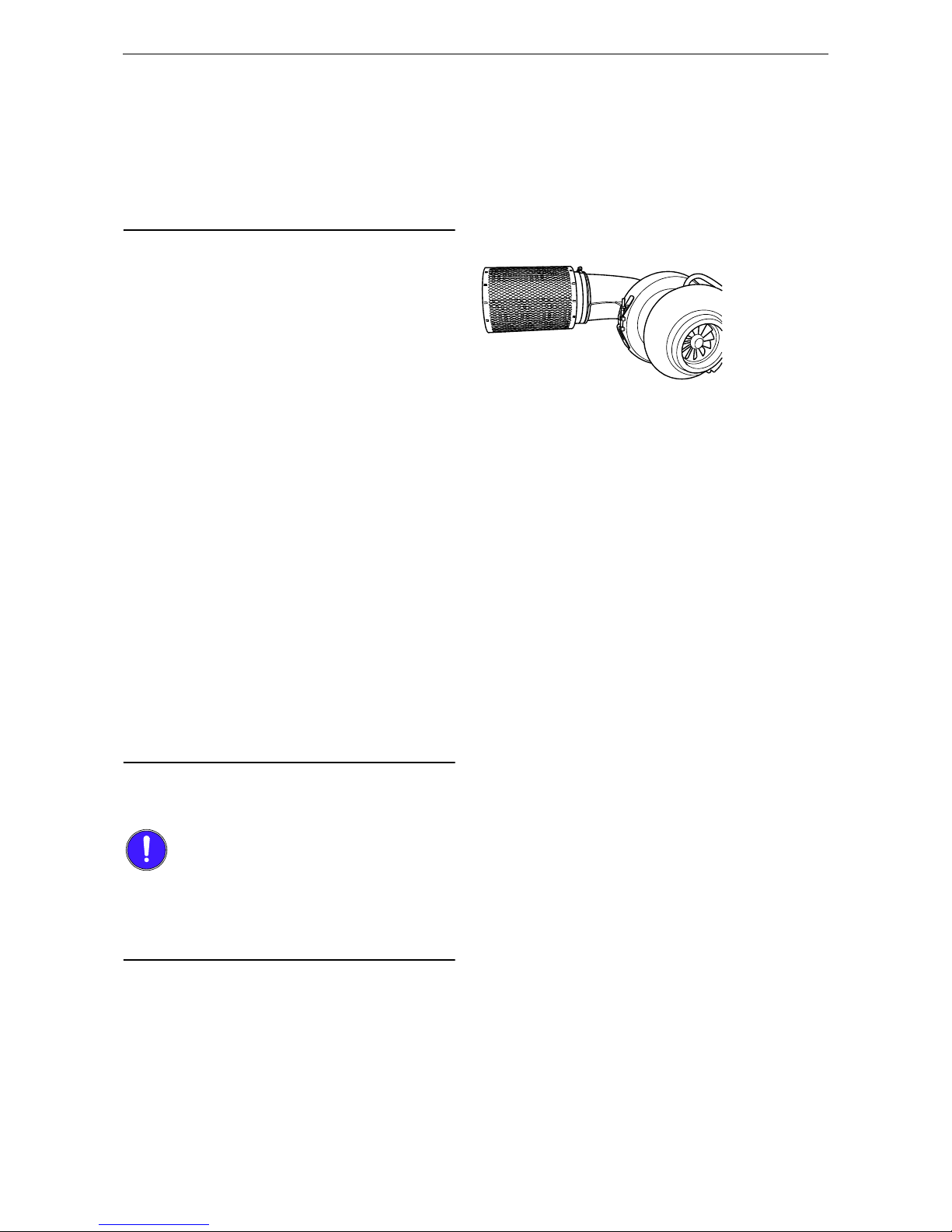
Renewing the filter element
Note:
Renew the filter element earlier than the inspection interval if the indicator shows red.
There is always a risk that the filter element will
be damaged when it is cleaned.
The filter element must not be cleaned in water
or be blown clean with compressed air.
WARNING!
Never start the engine without the air filter as this
could cause injury and severe engine damage.
1. Remove the cover from the air cleaner.
2. Renew the filter element.
3. Carry out a check by inserting an inspection
lamp into the element and checking from the
outside that there are no holes or cracks in the
filter paper.
4. Assemble the air cleaner.
5. Reset the vacuum indicator by pressing the
button.
326 671
A B
336 100
A Vacuum gauge
B Filter element
Page 57
OPM 250 en-GB 57
©
Scania CV AB 2016, Sweden
Air cleaner
Filter with a non-renewable
element
Note:
Scania recommends that the filter should be renewed rather than cleaned.
• The filter may be cleaned a maximum of 3
times. Mark the filter after each time it has
been cleaned.
• Use a cleaning solution consisting of water
mixed with approx. 1% mild detergent.
1. Pour the cleaning solution into the filter out-
let at the same time as turning the filter so
that the cleaning solution pours through the
filter against the direction of the air flow.
2. Leave the filter in the cleaning solution for 5
minutes and then take it out so that all the
cleaning solution drains away.
3. Rinse the filter with 30 litres of clean water
at a temperature of 30 to 40°C.
4. Take out the element and allow the rinsing
water to drain off.
5. Repeat this procedure until the rinsing water
is clean.
6. Leave the element to dry in a warm place for
a few days.
Note:
The filter must not be dried with compressed air.
Renewing the safety cartridge
IMPORTANT!
When renewing the safety cartridge, take great
care to ensure that no dirt or other impurities get
into the engine. Do not remove the safety cartridge unnecessarily.
1. Remove the cover from the air cleaner.
2. Remove the filter element.
3. Remove the safety cartridge.
4. Fit a new, genuine safety cartridge.
5. Renew or clean the filter element.
6. Assemble the air cleaner.
325 166
Page 58
OPM 250 en-GB 58
©
Scania CV AB 2016, Sweden
Fuel system
Fuel system
Sulphur content in fuel and its effect on oil
change interval
• A sulphur content of 0-2,000 ppm in the fuel
gives an oil change interval of up to 500
hours.
• With a sulphur content of 2,000-4,000 ppm in
the fuel, the oil change interval is halved to
max. 250 hours.
Checking fuel level
• Check the fuel level and top up with fuel as
necessary.
Note:
The fuel system must be bled if the tank has been
run dry. Refer to the Bleeding the fuel system
section.
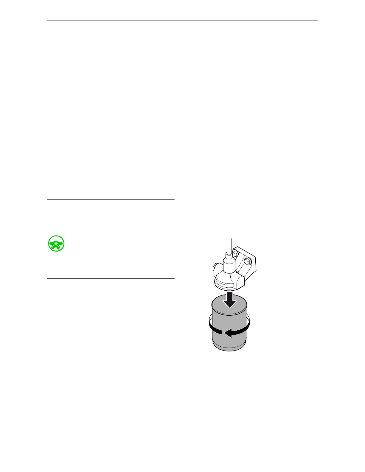
Renewing the fuel filter
Environment
Avoid spillage and use a suitable container. Used
fuel must be disposed of as specified in national
and international law.
1. Clean the exterior of the filter with a damp
cloth.
2. Unscrew the filter.
3. Apply oil to the gasket on the new filter.
4. Screw the filter into place by hand until it
makes contact.
5. Turn screw a further half turn by hand.
6. Then bleed the fuel system as per instruc-
tions.
325 167
Page 59
OPM 250 en-GB 59
©
Scania CV AB 2016, Sweden
Fuel system
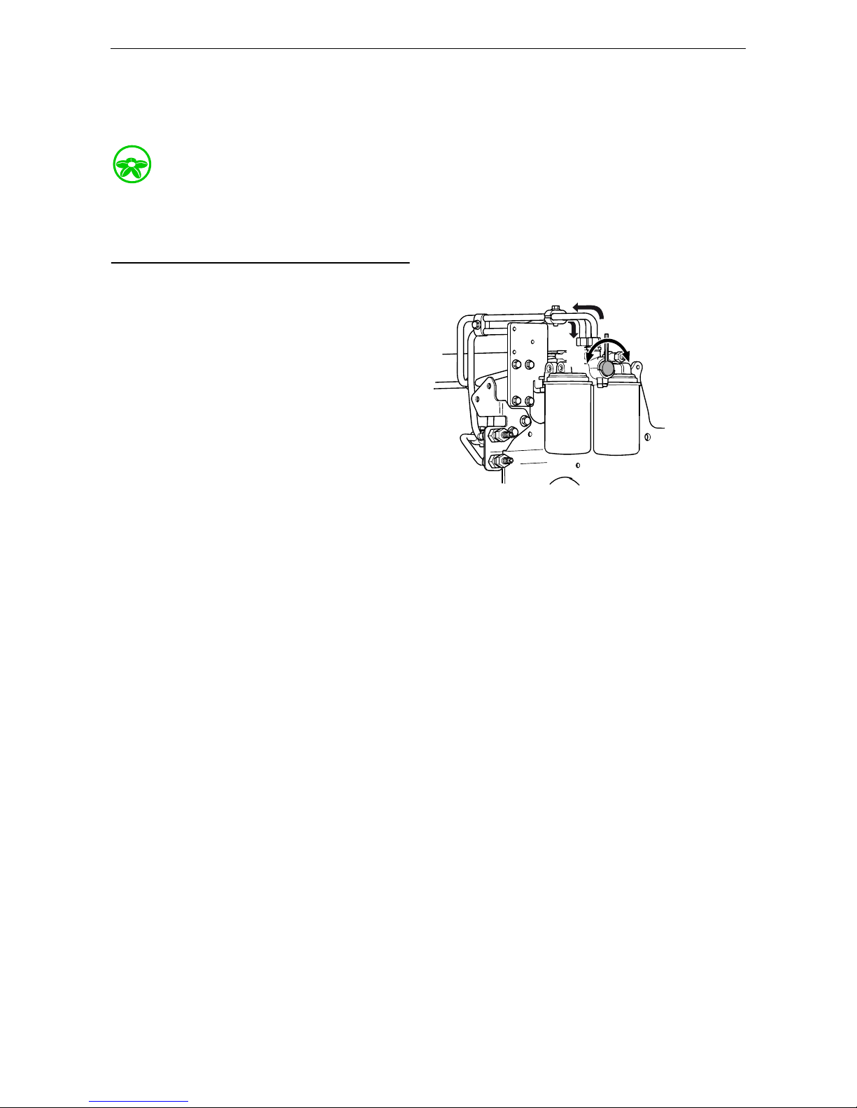
Renewing and bleeding double, commutative fuel filters
Environment
Since the engine may be running during filter renewal, fuel may spill. Use a suitable container.
Used fuel must be disposed of as specified in national and international law.
While running, the rotary control should point
90° towards the filter used.
1. Turn the rotary control 90° to the right so that
it points towards filter B. The fuel then flows
through the filter.
2. Connect a transparent plastic hose to the
bleed nipple located above filter A. Place the
other end in a container with a capacity of at
least 3 litres (1 US gallon).
3. Open the bleed nipple on side A; the remain-
ing pressure is released.
4. Clean the exterior of the filter with a cloth.
5. Unscrew the filter.
6. Apply oil to the gasket on the new filter.
7. Screw the filter into place by hand until it
makes contact.
8. Turn screw a further half turn by hand.
9. Turn the rotary control 90° to the left so that
the rotary control points straight up. Both filters now run simultaneously.
10. When fuel without air bubbles comes out,
close the bleed nipple. Because the engine is
running, a lot of fuel will come through the
hose.
11. Turn the rotary control 90° to the left so that
the pin points towards filter A. Filter B can
then be renewed following the procedure described for filter A.
AB
B
A
325 340
Page 60

OPM 250 en-GB 60
©
Scania CV AB 2016, Sweden
Fuel system
Renewing the water separating fuel filter
1. Close the shut-off cock in the fuel pipe and
position a container under the filter.
2. Undo the sensor cable from the connector on
the filter bracket.
3. Open the drain tap in the filter cover and let
the fluid run down into the container.
4. Unscrew the filter cover.
5. Unscrew the filter from the filter head.
6. Discard the old filter and use a new filter.
7. Lubricate the O-ring in the filter cover with
engine oil.
8. Screw the filter cover onto the new filter by
hand. Make sure that the drain tap is fully
closed.
9. Lubricate the O-ring on the filter with engine
oil.
10. Fill the width of the filter with clean fuel.
11. Screw the filter into position until the O-ring
rests against the filter head. Tighten the filter
another 1/2-3/4 turn by hand.
12. Open the shut-off cock and check the system
for leaks.
13. Connect the sensor cable to the connector on
the filter bracket.
14. Bleed the fuel system.
IMPORTANT!
The sensor cable is sensitive. Handle it carefully.
2
3
4
1
336 101
1. Sensor cable
2. Drain tap
3. Filter cover
4. Filter
Page 61

OPM 250 en-GB 61
©
Scania CV AB 2016, Sweden
Fuel system
Bleeding the fuel system
1. Attach a clear plastic hose to the bleed nipple
on the fuel manifold. Place the end of the
plastic hose in a container that holds at least
3 litres (1 US gallons).
2. Open the bleed nipple and pump with the
hand pump until fuel comes out of the hose.
If the fuel system is empty, it is necessary to
pump approximately 200 strokes in order to
draw up the fuel. Depending on the installation, a much greater number of pump strokes
may be required before fuel comes out.
3. Pump until fuel without air bubbles comes
out.
4. Close the bleed nipple on the fuel manifold
and remove the plastic hose.
5. Pump approximately 20 strokes with the
hand pump until the overflow valve opens. A
hissing sound should be heard.
6. Start the engine. The engine should be easy
to start.
7. If the fuel filter has been renewed, check that
no fuel is leaking from the filter. The fuel filter may then need to be tightened further.
325 169
Page 62
OPM 250 en-GB 62
©
Scania CV AB 2016, Sweden
Miscellaneous
Miscellaneous
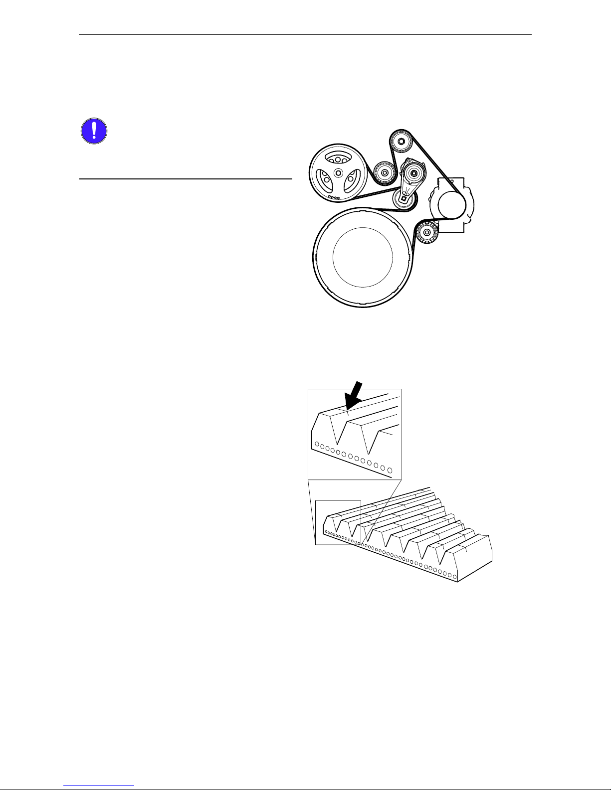
Checking the drive belt
IMPORTANT!
Refit the drive belt with the same direction of rotation as it had before removal.
Check the drive belt thoroughly, particularly at
the idler rollers.
Check the drive belt for cracks.
325 162
106 229
The drive belt must be renewed if it has cracks.
Page 63

OPM 250 en-GB 63
©
Scania CV AB 2016, Sweden
Miscellaneous
Check drive belt wear.
112 931
The drive belt is starting to become worn, but can be
refitted.
112 932
The belt is worn down to the cord. The drive belt
must be renewed.
Page 64

OPM 250 en-GB 64
©
Scania CV AB 2016, Sweden
Miscellaneous
Checking for leaks
• Start the engine.
• Check for oil, coolant, fuel, air or exhaust
leaks.
• Tighten or renew leaking connections. Check
the overflow holes which show whether the
O-rings between the cylinder liners and
crankcase are leaking.
IMPORTANT!
If serious leakage occurs, contact your nearest
Scania workshop.
Checking and adjusting the
valve clearance
Note:
Checking and adjusting valve clearances should
also be done after the first 500 hours of operation.
Valve clearances should be adjusted when the
engine is cold, at least 30 minutes after running.
WARNING!
Block the starting device when working on the
engine. If the engine starts unexpectedly, there is
a serious risk of injury.
Readings can be taken from the flywheel through
openings in the flywheel housing either from
above or below depending on access when fitting.
“TDC up” or ”"TDC down" is found on the flywheel. Both openings are fitted with a blanking
piece on delivery.
310 343
Openings for taking readings on the flywheel housing.
Page 65

OPM 250 en-GB 65
©
Scania CV AB 2016, Sweden
Miscellaneous
Specifications
Valve clearance, intake
valve
0.45 mm (0.018 in)
Valve clearance, exhaust valve
0.70 mm (0.028 in)
Tightening torques
Lock nut for valves 35 Nm (26 lbf/ft)
Lock nut for unit injectors
39 Nm (29 lbf/ft)
312 879
Special tool 99 309 is used when turning from below.
312 878
Special tool 99 109 is used when turning from
above.
314 829
Special tool 99 442 is used to check the height of the
unit injectors.
Page 66

OPM 250 en-GB 66
©
Scania CV AB 2016, Sweden
Miscellaneous
• Turn the flywheel in the engine's direction of
rotation so that TDC down or TDC up is visible in the flywheel housing window.
• Check the valve transition and start adjusting
as indicated in the table.
Checking and adjusting the unit injector
The unit injectors are adjusted using setting tool
99 442 or a digital sliding caliper.
From below Valve transition Valve adjust-
ment
Injector From above
TDC down 1 6 2 TDC up
120/480 5 2 4 300/660
240/600 3 4 1 60/420
TDC down 6 1 5 TDC up
120/480 2 5 3 300/600
240/600 4 3 6 60/420
1
A
B
a
314 823
Dimension A = 69.9 +/- 0.1 (2.75 in)
Dimension B = 38.8 (1.53 in)
Page 67

OPM 250 en-GB 67
©
Scania CV AB 2016, Sweden
Miscellaneous
8.
Fit the setting tool with the metal plate
around the unit injector
WARNING!
Be very careful when checking the unit injector
if the measurement is outside the setting dimension. The spring is pre-tensioned and can come
loose, causing personal injury.
9. When adjusting, undo the lock nut around
the adjusting screw and adjust the unit injector with the adjusting screw 1.
The unit injector is correctly set when the
small piston 2 is level with the flat upper surface of the tool. Use a finger to check. The
setting dimension is 69.9 +/- 0.1 mm (2.75
in).
314 831
1
2
314 832
Page 68

OPM 250 en-GB 68
©
Scania CV AB 2016, Sweden
Diesel
Diesel
Composition of the fuel
The composition of the fuel is extremely important for the operation and service life of the engine and injection system. The engine output and
exhaust gases are also dependent on the fuel
grade.
The requirements and testing standards for the
most important characteristics are described in
the Workshop Manual which can be ordered
from Scania dealers or directly from Scania.
The fuel must conform to EU standard EN590.
The table shows some of the key properties.
Sulphur content of fuel
• A sulphur content of 0-2,000 ppm in the fuel
(0.2%) gives an oil change interval of up to
500 hours.
• With a sulphur content of 2,000-4,000 ppm in
the fuel, the oil change interval is halved to
max. 250 hours.
• Maximum permitted sulphur contents in the
fuel is 4,000 ppm.
Using DMX and DMA fuels in
marine engines
DMX and DMA fuels normally cause increased
wear on the injection system. As a result of the
high sulphur content in these fuels the engine oil
is also affected. The engine oil must have as high
a Total Base Number (TBN) as possible.
REQUIREMENT!
For engines running on DMX and DMA fuels the
engine oil must have a TBN of at least 12.
Property Requirements
Viscosity at 40°C (104°F) 2.0-4.5 cSt
Density at 15°C (59°F) 0.82-0.86 cSt
Ignitability (CET rating) minimum 49
Flashpoint 56°C (132°F)
Page 69

OPM 250 en-GB 69
©
Scania CV AB 2016, Sweden
Diesel
When the engine is taken into operation the engine oil must be analysed every 50 hours to determine the correct oil change interval. The oil
analysis must be carried out according to the Oil
analysis section in this Operator's manual.
Bear in mind that the emission limit for the current engine type may limit the maximum permitted sulphur content of the fuel.
Temperature dependency of
the fuel
At temperatures lower than those specified for
the fuel, paraffin wax may precipitate from the
fuel and block filters and pipes. The engine can
then lose power or stop.
The fuel is adapted for use in the specific climate
of each country. If a vehicle or an engine is to be
operated in a temperature zone with a temperature lower than normal, first identify the temperature properties of that particular fuel.
The properties of the fuel when cold can be improved by adopting one of the following measures before the temperature drops:
• Install an electric fuel heater if this particular
fuel is not suitable for the expected temperature and no fuel is available with the correct
temperature properties.
• Add 0.5-2% alcohol (isopropanol) to prevent
any water in the fuel from freezing and forming plugs of ice. Drain fuel tanks and drain or
renew fuel filters regularly.
IMPORTANT!
Mixing kerosene or other paraffins with the fuel
is prohibited. The injectors may be damaged.
Mixing petrol with the fuel is prohibited. In the
long term petrol can cause wear in the injectors
and engine.
Page 70

OPM 250 en-GB 70
©
Scania CV AB 2016, Sweden
Preparing the engine for storage
Preparing the engine for
storage
If the engine is not being used for an extended
period its cooling system, fuel system and combustion chamber and outside must be protected
against rust.
An alternative to preparing the engine for longterm storage is to start the engine and warm it up
every 6 months.
Handling the engine
The engine can normally stand idle for up to 6
months without preparation. For longer periods
of downtime, the following measures should be
taken. These measures provide protection for approximately 4 years.
Preparations for storage:
• Thoroughly clean the engine.
• Run the engine for a specific period using
special preservative fuel, oil and coolant.
• Otherwise prepare the engine for storage (filter renewal, lubrication, etc.).
Preservative coolant
If the engine is to be stored with a full cooling
system, use coolant containing 50 percent glycol
by volume. Glycol without nitrite-based inhibitor should be used. Example: BASF G48 or
BASF D542.
WARNING!
Ethylene glycol can be fatal if ingested. Avoid
contact with the skin.
Page 71

OPM 250 en-GB 71
©
Scania CV AB 2016, Sweden
Preparing the engine for storage
Preservative fuel
Use diesel mixed with Lubrizol 560H or the
equivalent. Mix 1 cm
3
(ml)/0.06 in3 Lubrizol
560H in 10 dm
3
/2.3 US gallons of fuel.
WARNING!
Lubrizol 560H contains aromatic hydrocarbons
which are hazardous to health.
• Use spot extractors where there is a danger of
vapour build-up.
• Wear protective goggles and gloves when
handling the fuel.
• Do not use contaminated clothing.
• If it gets in your eyes: Flush with a gentle jet
of water for at least 15 minutes and contact a
doctor.
• If it gets on your skin: Wash with soap and
water.
• If you inhale it: Fresh air, rest and warmth.
• Store in well-sealed containers in a dry, cool,
place out of the reach of children.
Lubrizol is flammable and has a 2A fire rating.
The flashpoint is +27°C/81°F. In case of fire: Extinguish with carbon dioxide, powder or foam.
Preservative oil
Suitable preservative oils are supplied by most
oil companies. Example: Dinitrol 40 or equivalent.
Page 72

OPM 250 en-GB 72
©
Scania CV AB 2016, Sweden
Preparing the engine for storage
Preparations for storage
Environment
Use a container to avoid spills when draining the
oil and coolant. Dispose of used fluids through
an authorised waste disposal contractor.
1. Drain and flush the cooling system. Top up
with preservative coolant.
2. Warm up the engine on normal fuel. Stop the
engine and drain the oil.
3. Renew the fuel filter.
4. Fill the engine with preservative oil up to the
minimum level on the oil dipstick.
5. Mix preservative fuel in a can. Detach the
fuel pipe at the feed pump suction line and
connect a hose from the can.
6. Detach the fuel pipe at the overflow valve
and connect a return hose to the can.
7. Start the engine and run it at about 1,000 rpm
for 20-25 minutes.
8. Stop the engine, remove the hoses and con-
nect the normal fuel pipes.
9. Remove the rocker covers and lubricate the
valve mechanisms with plenty of preservative oil. Refit the rocker covers.
Note:
Do not remove the injectors.
Page 73

OPM 250 en-GB 73
©
Scania CV AB 2016, Sweden
Preparing the engine for storage
10.
Drain the preservative oil from the engine.
Fill with new engine oil immediately or
when the engine is to be reused.
11. Drain the coolant if the engine is not to be
stored with coolant in the system. Plug and
tape all coolant connections if the engine is
to be stored without a cooling system.
12. Air cleaner: Clean or renew the filter ele-
ment.
13. Cover air intakes and exhaust pipes.
14. Alternator and starter motor: Spray with wa-
ter-repellent anti-corrosive oil, CRC 226,
LPS1 or the equivalent.
15. Spray the outside of bright engine parts, first
with penetrating preservative oil such as
Dinitrol 25B and then with Dinitrol 112 or
the equivalent.
Clearly mark the engine with the storage preparation date, and state that the engine must not be
started or cranked.
Batteries
Remove the batteries and trickle charge them at
the battery charging station. This does not apply
to batteries specified as maintenance-free by the
manufacturer.
The same applies to short-term storage, even if
the engine has not been prepared for storage as
above.
WARNING!
Wear gloves and protective goggles when charging and handling batteries. The batteries contain
a highly corrosive acid.
Page 74

OPM 250 en-GB 74
©
Scania CV AB 2016, Sweden
Preparing the engine for storage
Storage
After the preparations, the engine should be
stored in a dry and warm place (room temperature).
When the engine is to be taken into
operation again
1. Remove plugs and tape from coolant connec-
tions, air intakes and exhaust pipes.
2. Fill the cooling system with coolant. For
more information refer to the section headed
Inspection.
3. Check the oil level in the engine or top up
with fresh engine oil.
4. Lubricate the valve mechanisms and their
pushrods and valve tappets as well as the injector mechanisms with plenty of oil.
5. Drain the preservative fuel from the fuel
manifold and fuel filter.
6. Connect and bleed the fuel system. For more
information refer to the section headed Inspection.
7. Wash off any preservative oil on the outside
using white spirit.
Page 75

OPM 250 en-GB 75
©
Scania CV AB 2016, Sweden
Technical data
Technical data
General data
Lubrication system
Number of cylinders and configuration 6, straight
Working principle 4-stroke engine
Cylinder diameter (mm/in) 130/5.12
Piston stroke (mm/in) 160/6.3
Displacement (dm
3
/in3)
12.7/775.0
Firing sequence 1 - 5 - 3 - 6 - 2 - 4
Compression ratio
DI13 070//071/072/073/077/078M 16.3:1
DI13 080/081/082M 17.3:1
Engine direction of rotation viewed from rear Anti-clockwise
Fan direction of rotation viewed from front Clockwise
Cooling Coolant
Valve clearances, cold engine
Intake valve (mm/in) 0.45/0.018
Outlet valve (mm/in) 0.70/0.028
Number of teeth on the flywheel 158
Low idling speed (rpm) 600-750
Maximum full-load speed (rpm) 2,300
Fuel Diesel
Approximate weight, without coolant and oil (kg/lb)
With heat exchanger 1,190/2,624
With keel cooling 1,140/2,513
Without heat exchanger and liquid-cooled charge air cooler 1,123/2,476
Oil volume See Inspection
Oil cleaning Centrifugal oil cleaning
Oil cooler Coolant cooled, full
flow
Oil filter Paper filter, full flow
Interval between oil changes (h) 500
Oil grade
Engines run on low-sulphur fuel ACEA E5 or E7
Engines not run on low-sulphur fuel Total Base Number
(TBN) > 12
(ASTM 2896)
Oil pressure (bar)
Normal with the engine at operating temperature, operating speed 3-6
Minimum permitted at idling speed 0.7
Page 76

OPM 250 en-GB 76
©
Scania CV AB 2016, Sweden
Technical data
Crankcase pressure with closed crankcase ventilation (mbar) -5.4 to 2.0
Page 77

OPM 250 en-GB 77
©
Scania CV AB 2016, Sweden
Technical data
Injection system
Cooling system
Intake system
Electrical system
Type PDE (unit injector)
Control system EMS
Fuel filter Paper filter from Scania
Fuel filter with water separator Paper filter from Scania
Coolant volume, excluding radiator (dm
3
/US gallons)
With heat exchanger 40/10.6
With keel cooling, 1 coolant circuit 24/6.3
With keel cooling, 2 coolant circuits 20/5.3
Without heat exchanger and liquid-cooled charge air cooler 20/5.3
Coolant temperature (°C/°F)
With heat exchanger 90-95/194-203
With keel cooling 83-88/181-190
Without heat exchanger and liquid-cooled charge air cooler 83-88/181-190
Number of thermostats 1
Thermostat opening temperature (°C/°F)
With heat exchanger 80/176 and 87/187
With keel cooling 75/167
Without heat exchanger and liquid-cooled charge air cooler 75/167
Permissible pressure drop in the intake system with cleaned or new filter (mbar)
30
Permissible pressure drop in the intake system with blocked (dirty) filter (mbar)
65
Type 2-pin, 24 V, DC
Starter motor, standard equipment 2-pin, 24 V, 7.0 kW
Alternator, standard equipment 2-pin, 28 V, 100 A
Page 78

OPM 250 en-GB 78
©
Scania CV AB 2016, Sweden
Scania Assistance
Scania Assistance
Wherever you are, you can always get assistance
from the Scania service organisation, Scania Assistance, all day, every day of the year.
Always call the contact for your country.
Other countries: +46 8 52 24 24 24
Note:
Calls will be recorded for training purposes.
AR 0800 999 722 642 IE +353 71 9634000
AT +43 1 256 44 11 IT +39 0461 996 222
AU 1300 SCANIA KR +82 1588 6575
1300 722642 LU +32 226 400 000
BE +32 2 264 00 00 MA +34 91 678 92 13
BG +359 886 660001 MX 01 800 4SCANIA
BR 0800 019 42 24 NL +31 70 4182666
CA +1-800-2-SCANIA NO +47 223 217 00
CH +41 800 55 24 00 PL +48 602 622 465
CL 188 800 722 642 PT +48 91 678 9247
CZ +420 225 020 225 RO +40 723 27 27 26
DE +49 261 887 8888 SE +46 42 100 100
DK +45 333 270 44 SK +421 903 722 048
ES +34 91 678 80 58 TR +90 212 335 04 40
FI +358 10 555 24 TZ +255 78 472 2642
FR +33 2 414 132 32 US 1-800-2-SCANIA
GB 0 800 800 660 UY 0800 8351
+44 1274 301260 ZA 0800 005 798
GR +30 6944 420 410 +27 11 661 9823
HU +36 209 727 197
 Loading...