

Page 1
05:05-02
Issue 1
Opticruise
Description of operation and work description
en
1 585 369
©
Scania CV AB 1995-10
100 830
Page 2

Contents
General Opticruise in brief ..............................................3
Introduction ........................................................4
Controls and operation .......................................6
Fault codes
Description of operation
Gear changing ....................................................7
Opticruise controls the engine via EDC ............ 7
Gear changing sequence, description ................ 8
Engine brake program ....................................... 9
Starting gear, programming .............................. 9
Kick-down ..........................................................9
Auxiliary brake system ......................................9
EDC cruise control .......................................... 10
ABS/TC ............................................................10
Power take-offs ................................................10
Configuration, control unit .............................. 11
Power supply and fuses ................................... 11
Interaction with other systems ........................ 12
Opticruise, design .............................................14
Warning system ................................................16
General .............................................................19
Faults that do not generate fault codes ............ 19
Electrical system
Mechanical work
Exploded view drawings
Clarifications, new terms ................................ 20
List of fault codes ....................................... 19-52
References to wiring diagrams ........................ 53
Location of electrical components .............54-55
Control unit signals .................................... 56-59
Driving mode selector ......................................60
Test program .............................................. 61-71
General .............................................................73
Instructions for repair and adjustment ....... 73-76
Components on gearbox ............................. 77-83
2
©
Scania CV AB 1995 05:05-02 en
Page 3
General
General
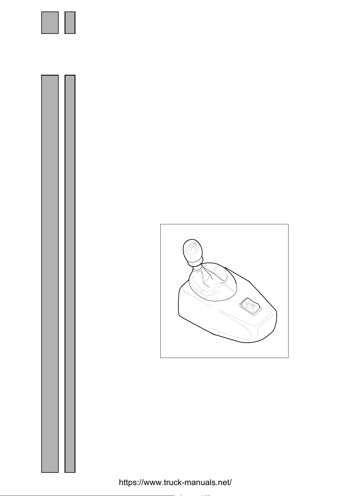
Opticruise in brief
Opticruise is a system which allows a normal
manual gearbox to shift automatically. The
clutch is retained but is used only when starting, stopping and shunting.
A control unit collects and processes data from
controls, sensors and adjacent systems such as
EDC, ABS/TC and auxiliary brake (if fitted).
When it is time to change gear, the control unit
actuates the solenoid valves, releasing compressed air to the air cylinders. These air cylinders then change to the required gear.
The control unit has an in-built warning system. Fault codes can either be read on the display or using a PC and the Scania Diagnos
program. The latter makes fault diagnosis
quicker.
05_5338
Opticruise requires that the vehicle be fitted
with both EDC and ABS/TC, due to the information exchange requirements between the
systems.
When changing gear, the engine speed is controlled so that the speeds of the gearbox input
shaft and output shaft correspond for the gear
to be engaged. Gear changing is only then
completed.
When necessary, the exhaust brake is used to
make changing up fast and smooth.
05:05-02 en
©
Scania CV AB 1995 3
Page 4
General
Introduction
Scania Opticruise is an automatic gear changing system for
manual gearboxes. Opticruise is constructed in more or less
the same way as the Scania CAG system, the major difference
being that the driver only needs to use the clutch pedal when
starting, stopping and shunting.
The system is able to change gear automatically without the
clutch because the engine is regulated to synchronous speed
for the gear that is to be engaged. This means that the electronics adapt both engine speed and torque to exactly the levels required by the gearbox. This makes all gear changing
gentle and precise, increasing the service life of the entire
powertrain.
Opticruise requires the engine to be equipped with EDC. It
would not be possible, using a mechanical injection pump, to
control the engine with the speed and precision required for
Opticruise to work smoothly. Opticruise also requires the
vehicle to be equipped with ABS/TC in order to select the
correct gear, even if the drive wheels lose grip on a slippery
road surface.
Using Opticruise, the driver can choose to drive with manual
or automatic gear selection. In manual gear selection driving
mode, the driver selects the gear and when it is changed
(depending on road speed and/or engine speed). The control
unit decides whether it is possible to change gear without the
driver using the clutch. If this is the case, the gear is immedi-
100 830
ately changed when the driver moves the driving mode selector sideways. Otherwise, the driver has to depress the clutch
pedal in order to change gear.
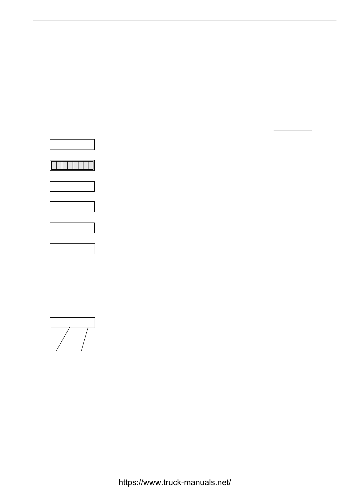
Normal
Hill
In automatic gear selection driving mode, the control unit calculates which gear is appropriate and carries out this shift
when the calculation is complete. In this case, gear changing
always takes place without the driver having to use the clutch
pedal. If the EDC cruise control is engaged, gear change is
automatic without the cruise control being disengaged. This
applies until speed is so low that it is a question of stopping or
shunting. The clutch must then be used.
In addition to the driving mode selector and its various positions, the driver can choose between two different driving
programs. This is done using a program selector beside the
driving mode selector. These programs are called Normal and
Hill. The Hill program is for steep upward slopes with more
than 5 % gradient.
100 830
4
©
Scania CV AB 1995 05:05-02 en
Page 5
CLU MODE
LIMPHOME
General
The control unit varies the point at which it changes gear,
depending on the position of the program selector. When driving with the program selector set to Hill, gear changing is
faster than when the Normal program is engaged. If necessary, the exhaust brake may also be used in order to quickly
reduce the speed of the engine.
Like the older CAG system, Opticruise has a selectable starting gear which is programmed in one of the control unit memories. The driver can easily select the starting gear for the
average gross train weight of the vehicle combination. The
control unit retains this setting, even when power is interrupted. In addition to this, the driver can temporarily select a
starting gear other than the one programmed in the memory.
This is fully described in the driver’s manual.
The control unit has a built-in warning system. This has made
it possible to reduce the inconvenience in the event of a fault.
Opticruise has two built-in emergency driving programs. The
first of these, clutch mode, is activated in the case of less serious faults and the driver has to depress the clutch pedal every
time a gear is changed. If the driving mode selector is set to
automatic, Opticruise still preselects the gear as normal. In
this situation, Opticruise works in the same way as Scania
CAG.
In the case of more serious faults, the driver should activate a
limp home program. This makes it possible to drive the vehicle to a workshop, even if something like a sensor is faulty.
This means that the vehicle can be run, even if the emergency
driving program feels basic with its manually-requested compressed air gear changes.
The Opticruise system interacts with the braking effect of the
diesel engine, the exhaust brake and the Scania retarder, if the
vehicle is fitted with this. This reduces brake wear, reducing
running costs. In addition, wear to the entire powertrain is
reduced as power is transferred more gently than on vehicles
with manual gearboxes.
However, the greatest advantage, not least financially, is of
course improved driver comfort. Opticruise enables the driver
to maintain concentration longer than when driving a vehicle
with manual gear changing. This is an advantage for both running costs and road safety.
05:05-02 en
©
Scania CV AB 1995 5
Page 6
General
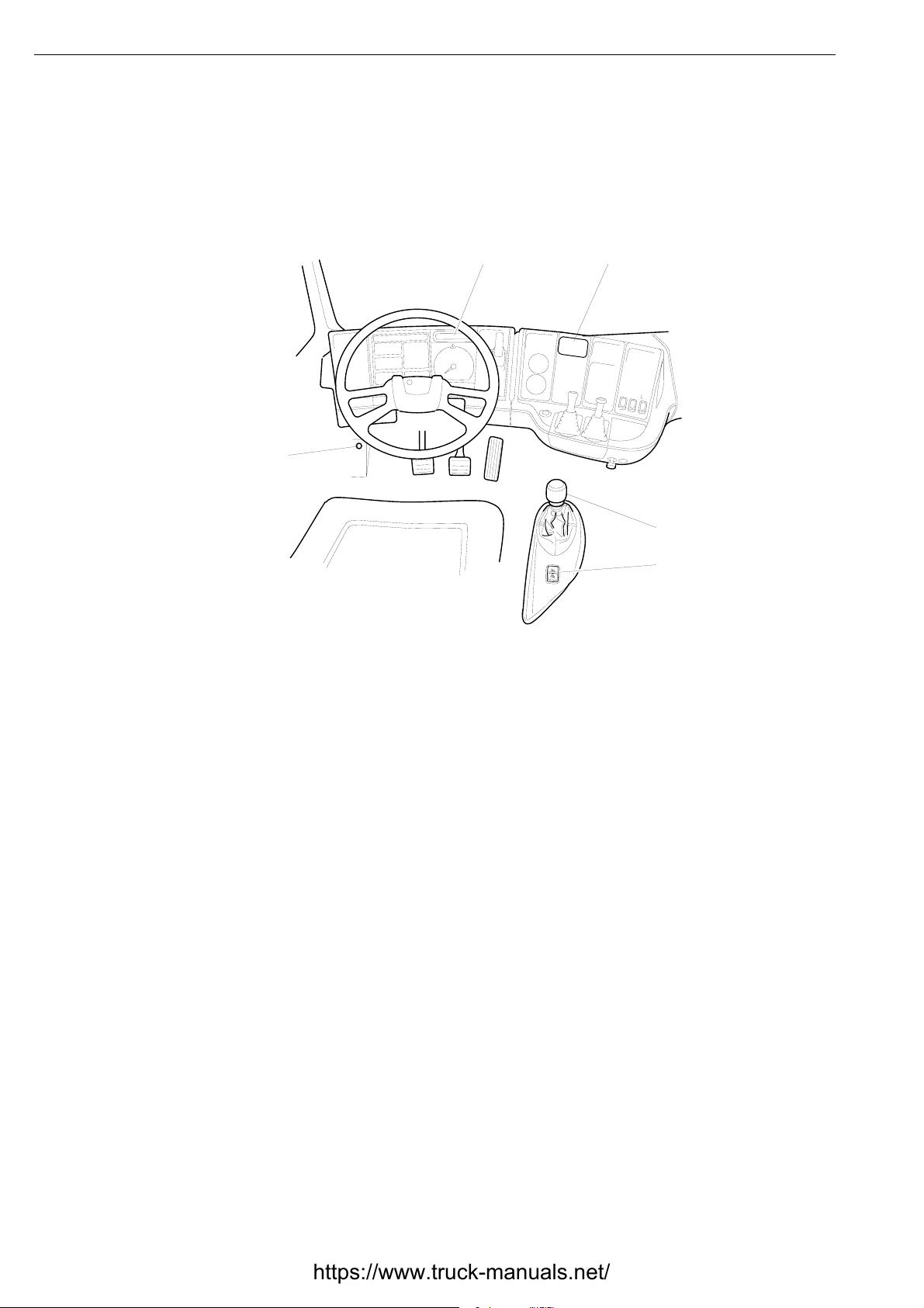
Controls and operation
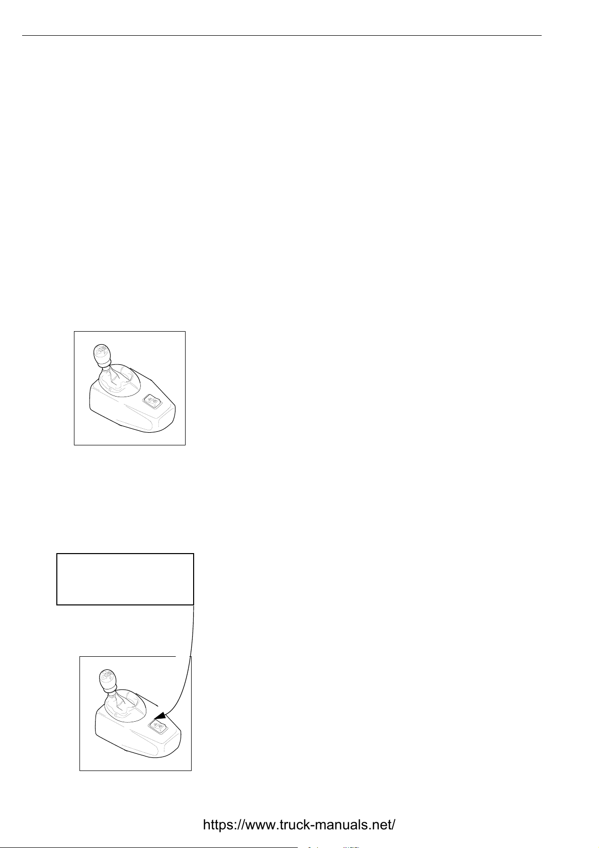
3
The above drawing shows the controls used for
Opticruise. The clutch pedal, controls for EDC
cruise control and auxiliary brake control unit
also affect the system.
5
4
1
2
100 829
1 Driving mode selector with positions R, N,
A and M. The driver is able to command up
and downshift by moving the selector lever
to the side.
For example, the auxiliary brake may request
that the engine brake program be activated in
order to increase engine speed and therefore
coolant flow. This is essential for optimum
retarder performance.
When driving with the cruise control, the system changes gear automatically provided the
driving mode selector is set the position A. The
cruise control is deactivated using the clutch
pedal, brake pedal, retarder lever, cruise control OFF button or using the exhaust brake
switch on the floor.
2 Program selector with Normal and Hill
positions. The Hill position is for use on
steep slopes, preferably with the driving
mode selector set to M (manual).
3
Switch for activating engine brake program and exhaust brake.
4
Diagnostics switch
5
Gear indicator with display and buzzer.
6
©
Scania CV AB 1995 05:05-02 en
Page 7

Description of operation
Description of operation
Gear changing
Driving in automatic position A means that the
system changes gear automatically in accordance with the driving program set using the
program selector, either ”Normal” or ”Hill”.
However, the gear selected automatically can
be changed at any time by the driver by moving the driving mode selector to the side. The
control unit always checks that the driver’s
selection is within reasonable limits.
The driver can even preselect a gear that
appears completely inappropriate under the circumstances, such as 3rd when driving in 7th.
There are two conditions that must be met for
this to work.
• The vehicle must lose speed (be retarded).
• The driving mode selector must be set to
manual and the program selector to Hill.
The gearbox then starts the shift by first going
to neutral. The control unit then prepares itself
for the correct splitter level, correct lateral
stroke and the correct range before road speed
is reduced sufficiently for the particular gear
change to be requested.
At the same time, engine speed is automatically increased to high idling, about 2500 rpm.
When road speed has decreased sufficiently,
the gear is engaged smoothly and gently. When
gear changing is complete, control of the
engine is returned to the driver.
When driving, the driver can at any time move
the driving mode selector to neutral (N) when,
for example, approaching a traffic light. If he
changes his mind and the vehicle is still moving, it is possible to move the driving mode
selector back to one of positions A or M. The
control unit then selects a suitable gear, based
on the speed of the vehicle and other information from sensors etc. It is not necessary to use
the clutch unless speed is too low.
From automatic position A, the driver can at
any time move the lever to manual position M
and vice versa. This can be useful if you, for
example, want to ”lock” a gear on a slippery
road surface. The same applies if he wants to
shift manually, for example on steep hills.
Note: On uphill slopes greater than 8 %, it may
be necessary to drive with the driving mode
selector set to M and with the program selector
set to ”Hill”. This gives the fastest possible
gear changing, which means that the vehicle
does not lose so much speed during changing.
Opticruise controls the engine via EDC
Gear changing when driving is done by
Opticruise controlling the engine via EDC to
synchronous speed for the gear that is about to
be engaged, without the driver using the clutch
pedal. This means that both engine speed and
torque are adjusted to precisely the level
required by the gearbox.
In order to make gear changing easier, engine
torque is reduced in a controlled manner just
before the gear is disengaged.
Gear changing takes place after the speed of
the moving parts in the gearbox has been synchronized.
Towards the end of gear changing, engine
torque increases in a gentle and controlled
manner to the level requested by the driver
using the throttle pedal. This means that gear
changing is always gentle and precise, increasing the service life of the entire powertrain.
This precise control is made possible by communication between the Opticruise and EDC
control systems.
05:05-02 en
©
Scania CV AB 1995 7
Page 8

Description of operation
Description of the gear changing process
1 Gear change requested automatically or by the driver.
2 Engine regulated so that there is no torque on the gearbox
input shaft.
3 Gearbox set to neutral.
4 Engine regulated to synchronize the speed of the gearbox
input shaft and the moving parts for the gear to be
engaged.
5 Gear engaged.
6 The engine is regulated to the required torque. The
Opticruise then returns control of the engine to the driver.
• During certain upshifts, the exhaust brake is used to more
quickly brake the engine to the correct speed in relation to
the gear selected.
• When driving in automatic (A), the control unit continuously calculates which gear is most suitable. When this calculation shows that a gear other than the one engaged
would be more suitable, the gear change takes place immediately. This may be either a single change or a block
change.
The calculation of appropriate gear is made based on the following data:
- Position of program selector
- Current road speed
- Current acceleration
- Current torque
- Total gear ratio
- Throttle pedal position
- Any request for the activation of the engine brake program
from the driver or from the auxiliary brake control unit.
8
©
Scania CV AB 1995 05:05-02 en
Page 9

Description of operation
Engine brake program
The function of the engine brake program is to
give optimum engine braking in all driving
conditions. The engine brake program has
nothing to do with the Normal/Hill program
selector, but is controlled by a separate switch
on the floor of the cab.
In order to use the engine brake program, the
throttle pedal must be fully released.
A short press on the floor switch is all that is
required to activate the engine brake program.
This means that upshift is delayed as the control unit maintains the gear for longer before
changing up, increasing engine brake output.
However, if the floor switch is held down all
the time, the exhaust brake is also engaged and
downshift takes place earlier.
If the brake pedal is held down, the upshift
points change. The control unit is informed of
this via the brake lamp switch.
The engine brake program is connected until
the throttle pedal is next depressed.
If the vehicle is equipped with an auxiliary
brake system with Scania retarder, the engine
brake program can be automatically engaged
(if appropriate) when using the retarder. This is
done by the auxiliary brake control unit. The
intention is to raise engine speed and thus coolant flow, providing the retarder with maximum
braking effect and activation time.
Programming start-off gear
The system permits free choice of starting gear
between 1st and 4th. 1st or 2nd are normally
used, but it may be appropriate to use another
one in extreme cases.
Note: When the vehicle is heavily loaded, 1st
or 2nd must be used. Otherwise, the clutch
will be subjected to excessive wear.
It may sometimes be necessary to start in a
gear other than the one programmed. This can
be done, irrespective of whether the driving
mode selector is set to A or M. Simply move
the driving mode selector to the side until the
required gear is shown on the display. The
vehicle can now be started. The ordinary starting gear remains programmed in the control
unit memory. More information can be found
in the driver’s manual.
Kick-down
By pressing the throttle pedal from full throttle
to kick-down, the gear changing points are
raised, usually causing faster downshift.
Auxiliary brake system
See ”Engine brake program”.
05:05-02 en
©
Scania CV AB 1995 9
Page 10

Description of operation
EDC Cruise control
When driving with the cruise control, the system automatically change gear if the driving mode selector is set to A. It is
however still possible to manually control gear selection in
both positions A and M, without disengaging the cruise control.
If the driving mode selector is set to N when the vehicle is
being driven with the cruise control activated, engine speed is
increased to high idling (i.e. the engine surges). The driver
should therefore disengage the cruise control before setting
the driving mode selector to N.
The cruise control is disengaged using the clutch pedal, brake
pedal, retarder lever, cruise control OFF button or the exhaust
brake switch on the cab floor.
ABS/TC
The Opticruise control unit communicates with the ABS/TC
system. If there is wheel lock (causing ABS control) or spin
(causing TC control), the Opticruise is very reluctant to
change gear and does so according to special criteria. When
the driving mode selector is set to A, the Opticruise endeavours to maintain the engaged gear.
Power take-offs
The control unit is configured for two types of power take-off,
PTO EK/ED and PTO EG.
PTO EK/ED provides torque compensation and therefore very
smooth gear changing if the vehicle is driven with an enginedriven power take-off engaged (Max. compensation 200 Nm).
If the ED120 is used to drive a hydraulic pump, there may be
a lack of space around the longitudinal stroke cylinder. If this
is the case, turn the longitudinal stroke cylinder the other way
and move the compressed air couplings so that they swap
places.
PTO EG is for gearbox-driven power take-offs. If the vehicle
is driven with this input signal active, all gear changing is
blocked. The text PTO also flashes on the display if the vehicle is driven above a certain speed.
10
©
Scania CV AB 1995 05:05-02 en
Page 11

Description of operation
Miscellaneous
Control unit configuration
The control unit contains all programming necessary for a number of different Scania versions. So that the control unit fits each Scania,
it must first be configured so that it uses the
correct program for the particular vehicle. This
is equivalent to the code plug in other (less
modern) control units, such as for CAG.
The required configuration is fed into the control unit at manufacture using a PC. Configuration may be changed later by qualified
personnel.
Configuration must contain the following
information:
• Vehicle category (e.g. truck)
• Chassis number
• Part No. for control unit software
• Gearbox type
• Engine type and version
Power supply and fuses
Generally, Opticruise continues to work if a
fuse blows while the vehicle is being driven. It
may, however, be impossible to start the system the next time.
The control unit is protected by two fuses:
• Fuse 41 is used for 30 supply.
• Fuse 5 is used for 15 supply.
Power to the control unit is usually interrupted
using the starter switch. What happens then is
that control unit 15 supply to pin 55 is broken.
When this happens, important data is transferred from the RAM to the EEPROM and
stored there until the next start. The control
unit then goes into rest state, despite the fact
that 30 supply from the batteries is still applied
to pin 19.
• If fuse 41 for 30 supply blows, or if a battery cable is removed, data cannot be transferred from the RAM to the EEPROM and
be stored. The control unit ”forgets” any
newly-programmed starting gear as well as
new fault codes.
• Rear axle ratio
• Wheel rolling radius
• End-of-line data (date, signature)
• If fuse 5 for the 15 supply blows, data is
transferred as normal from RAM to EEPROM and stored there. In this situation, the
control unit believes that the starter key has
been set to position 0. This means that it is
not possible to restart Opticruise until the
fault has been corrected.
05:05-02 en
©
Scania CV AB 1995 11
Page 12

Description of operation
Interaction with other systems
The figure opposite shows which other systems
are connected to Opticruise and in which
directions data is transferred.
Any faults are transmitted in the same
direction. This means that a fault in the
ABS/TC system can manifest itself in the
Opticruise system, but not vice versa.
Where appropriate, the figure applies to all
optional equipment affected.
• The Opticruise is coupled to the EDC system to enable synchronous control of the
speed of the gearbox input and output
shafts. The particular gear change does not
take place until these speeds correspond
with each other.
The communication between the Opticruise
and the EDC covers a wide range of data,
such as engine speed, requested and actual
torque, throttle pedal position, coolant temperature and cruise control.
Communication is via two CAN leads and is
for such things as executing engine-controlled gear changing and determining which
gear should be selected at any particular
time.
• Opticruise is coupled to the auxiliary brake
system to make it possible to engage the
engine brake program to optimize the
retarder and achieve maximum braking
power in kW.
When the auxiliary brake has requested the
exhaust brake to retard the vehicle, the
Opticruise will still be able to control the
exhaust brake for gear changing.
When the gear change is complete, the
exhaust brake will again be used to retard
the vehicle. Prioritization of the various
tasks of the exhaust brake is controlled by
the exhaust brake control unit (EEB).
If the vehicle has an auxiliary brake, the
Opticruise forwards the speed signal from
the speed sensor on the gearbox output shaft
to the auxiliary brake control unit.
• Opticruise is connected to the tachograph so
that it can use the speed information from
this to check that other speed signals are
reasonable.
12
• The Opticruise is coupled to the ABS/TC
system to receive information on ABS control, TC control, wheel speeds etc.
The communication between Opticruise and
ABS/TC is used for confirming such things
as the suitability of the gear selection. If the
wheels are spinning or slipping, Opticruise
would be “fooled” into selecting the wrong
gear. The speed of each wheel is also used
to check that other speed signals appear
plausible.
Communication is via the two CAN leads.
©
Scania CV AB 1995 05:05-02 en
Page 13
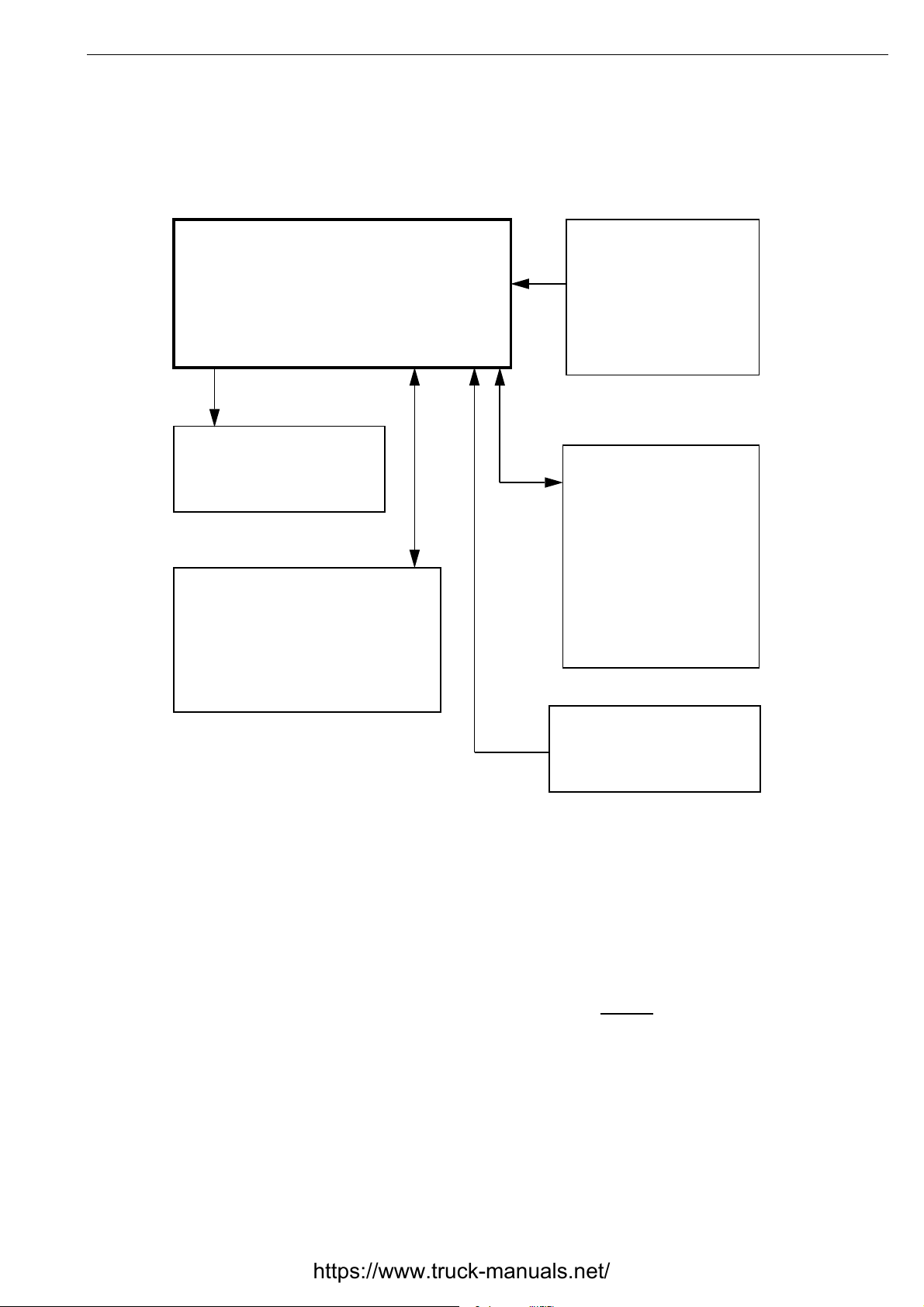
Opticruise
Exhaust brake
Description of operation
ABS/TC
Auxiliary brake
system with
Scania retarder
EDC
Tachograph
Signal paths between the Opticruise control unit
and other computer-controlled systems that
in the vehicle.
Any faults are transferred from one system to
another in the same direction as communication
(see arrows).
may be
05:05-02 en
©
Scania CV AB 1995 13
Page 14

Description of operation
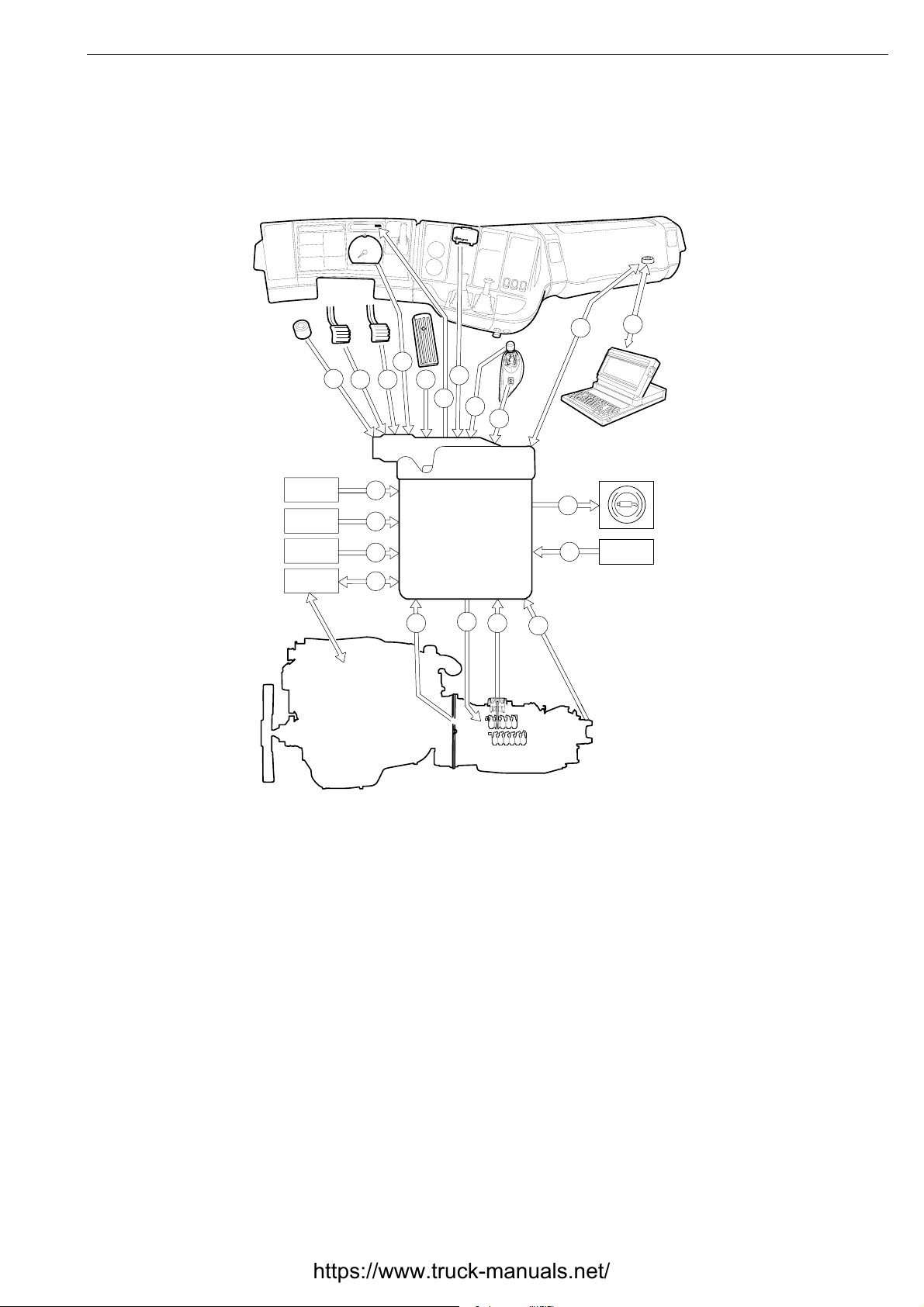
Opticruise, design
Item numbers refer to the drawing opposite.
1 The floor switch is used to activate the
engine brake program and exhaust brake.
In vehicles with no auxiliary brake, the
exhaust brake is used in combination with
the engine brake program when the floor
switch is held down. The signal goes via
the auxiliary brake control unit if the vehicle has this. Also see point 14.
2 Two switches provide data on the position
of the clutch pedal (released, partly or fully
depressed).
3 EDC informs the control unit that the
driver is braking. The engine brake program then uses slightly shifted upshift
points.
4 The tachograph provides a speed signal
which Opticruise compares with the other
speed signals. These come from ABS/TC
and the gearbox output shaft.
5 The throttle pedal sensor provides data on
requested throttle and kick-down. The
potentiometer signal goes via the EDC
control unit.
6 The gear indicator with display and buzzer
is used to display driving program, which
gear is engaged, fault messages etc.
8 The driving mode selector informs the con-
trol unit about requested driving mode and
if the driver wants to actuate the automatic
system by commanding a change up or
down.
12 The diagnostic switch is used to activate
the test program built into the control unit
and for erasing fault codes.
13 Opticruise receives information from
ABS/TC on speed, slip and possible wheel
spin in order to select the correct gear at
any moment. In addition, Opticruise must
be able to prevent gear change if the drive
wheels lose grip. This is for safety.
14 Opticruise uses the exhaust brake to adapt
engine speed during certain gear changing
procedures, but the exhaust brake is normally used to brake the vehicle.
The exhaust brake control unit prioritizes
requests depending on driving conditions.
The exhaust brake can be activated automatically, manually or by the auxiliary
brake control unit.
15 The engine speed sensor is used to be able
to synchronize the speeds of the gearbox
input and output shafts when changing
gear. The signal goes via the EDC and
through the communications circuit.
16 The solenoid valves on the gearbox carry
out each gear change by releasing compressed air to the longitudinal and lateral
stroke cylinders. In turn, the cylinders activate the gear selector shaft.
17 The hall effect sensor and the confirmation
switches monitor and confirm gear changing movement.
14
9 The program selector has two positions.
The Normal position provides optimum
fuel economy and the box changes gear
calmly and comfortably. The Hill mode
provides a faster gear changing cycle at
higher engine speed.
10 Diagnostic socket for PC via interface
(Scania VCI).
11 PC with Scania Diagnos 2 fault tracing
program provides the fastest result when
fault tracing.
©
Scania CV AB 1995 05:05-02 en
Page 15
Description of operation
The drawing below is general and applies to all optional equipment affected. Only relevant sections apply to vehicles with less equipment.
PTO EK/ED
PTO EG
RETARDER
EDC
10
4
1
3
2
21
22
20
19
12
5
6
8
OPTI−
CRUISE
15
16
17
9
14
13
18
11
ABS/TC
18 The speed sensor on the gearbox output
shaft is used to calculate vehicle speed and
to confirm other speed signals from
ABS/TC and the tachograph. A corresponding output signal is relayed to the
auxiliary brake control unit.
19 Control of engine torque and speed is
requested by Opticruise but carried out by
EDC. Just when Opticruise is controlling
the engine, the control unit continuously
checks that actual torque corresponds to
the requested level.
20 The auxiliary brake system control unit can
request Opticruise to activate the engine
brake program.
100862
21 PTO EK/ED provides torque compensa-
tion during engine-controlled gear changing and therefore an excellent level of
comfort if the vehicle is driven with an
engine-driven power take-off engaged.
22 PTO EG is for gearbox-driven power take-
offs. When this input signal is active, all
gear changing is blocked and the clutch
cannot be used.
05:05-02 en
©
Scania CV AB 1995 15
Page 16
Description of operation
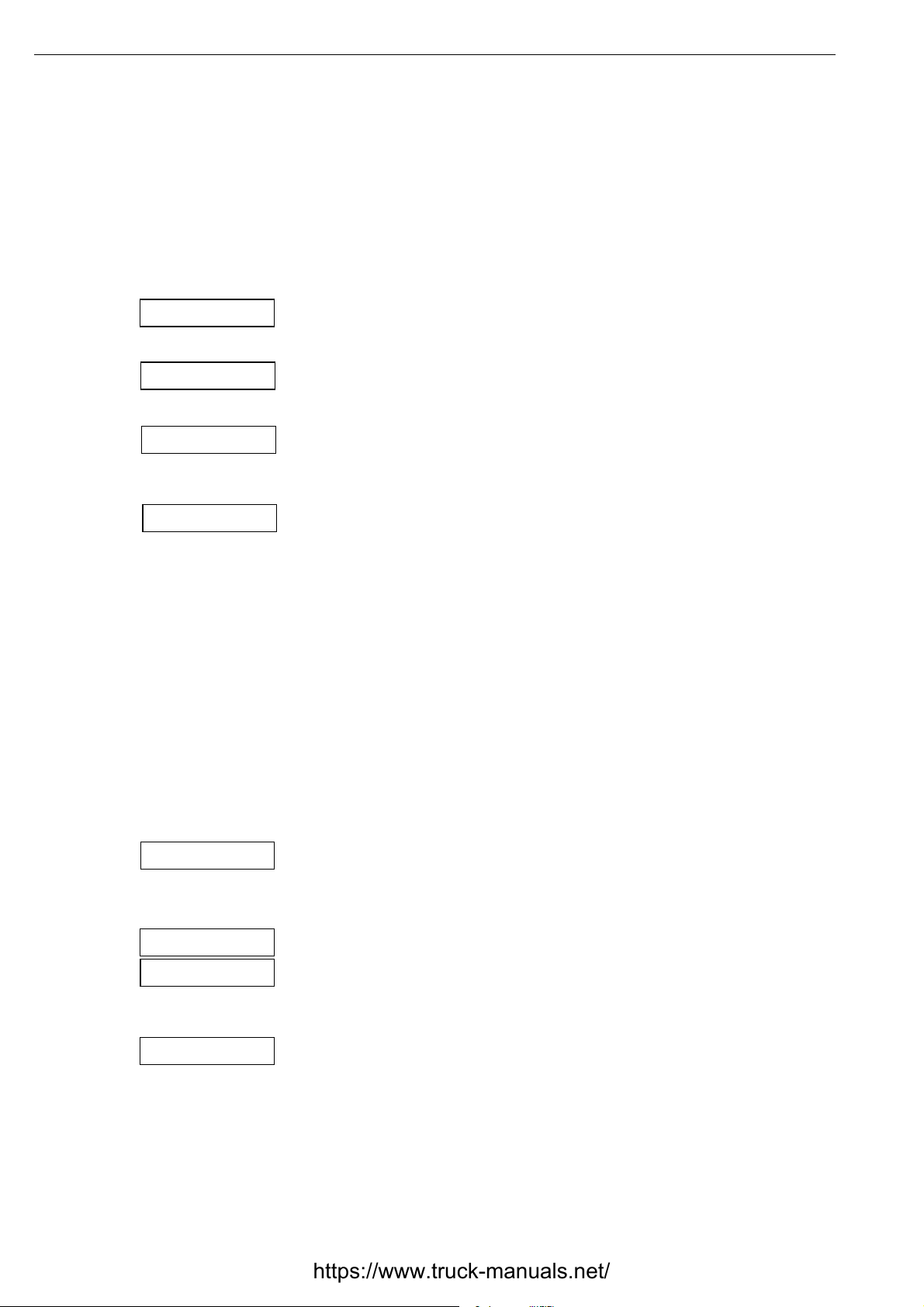
Warning system
The control unit takes various action in the case of faults. This
is to prevent the fault having expensive consequences. For
example, the control unit has two different emergency gear
changing programs. The first of these still provides good drivability while the second requires more from the driver. The
intention of this is that minor faults should not cause too much
inconvenience.
CLU MODE
C
NORMAL
FAILURE
Certain types of less-serious fault cause the control unit to
switch from normal operation to the simpler of the two emergency gear changing programs. The text ”CLU MODE”
(clutch mode) is shown on the gear indicator display. In this
case, the driver is required to use the clutch for each gear
change. While the control unit is working in this mode, the
letter C will be displayed near the left of the display.
If the fault disappears on its own, the control unit immediately
returns to normal operation. The display then shows ”NORMAL”.
In the case of more serious faults, ”FAILURE” is displayed. If
this happens when driving, the control unit locks the engaged
gear. This gear alone is shown on the display. The driver must
then stop the vehicle and activate the ”LIMPHOME” emergency gear changing program. This process is described in
detail in the Opticruise driver’s manual.
16
CHK CODE
ERROR1
ERROR2
CONFIG
Fault code messages
When the driver switches off the power, the message ”CHK
CODE” is displayed if the control unit has stored any fault
codes during driving. This message is repeated when the
power is switched back on again.
”ERROR1” or ”ERROR2” means that the control unit has
supplied faulty signals or no signals to the display. A PC must
be used to read any fault codes.
”CONFIG” means that the configuration of the control unit is
not correct. In this case, change the configuration of the control unit using a PC and Scania Programmer.
©
Scania CV AB 1995 05:05-02 en
Page 17
Description of operation
Reading fault codes
Fault codes are read in the first part of the Opticruise test program. This test program is described in full on pages 59 - 69
of this booklet.
However, describing how to read fault codes would be a suitable introduction to the list of fault codes in the next chapter
and the method is therefore also shown here.
1 Stop the vehicle and switch off the engine.
TESTING
ECU NO
PROG NO
CHASSNO
F CODES
2 Switch on the power using the starter key.
seconds and then hold the diagnostic switch depressed for
at least a half second. Release it. ”TESTING” is shown on
the display and the buzzer sounds.
Do not touch the diagnostic switch for the moment. The
test program has now started. All parts of the display light
for one second and the buzzer sounds.
3 ”ECU NO” is displayed, directly followed by the part
number of the control unit hardware.
4 ”PROG NO” is displayed, directly followed by the part
number of the control unit software.
5 ”CHASSNO” is displayed, directly followed by the vehi-
cle chassis number.
6 ”F CODES” is displayed, directly followed by any fault
codes stored. More on this below.
• The fault codes are displayed one at a time, with two seconds between them.
Wait for five
E010 003
A
B
• When all stored fault codes have been displayed, the
buzzer sounds briefly. The stored fault codes are then displayed again. This may be repeated any number of times,
so there is no danger if you should lose concentration.
The display can, for example, look like the figure to the
left. A shows the number of the fault code (10 in this case)
and B shows how many times this fault code has been registered (3).
7 Make a note of the fault codes. Run through the test pro-
gram. Press the diagnostic switch to switch between the
various stages of the test. See pages 59 - 69.
05:05-02 en
©
Scania CV AB 1995 17
Page 18
Description of operation
Erasing fault codes
It may be necessary to reset the warning system
every now and then. Someone may, for example, have unplugged a cable while the power
was switched on. This can easily happen and the
control unit will then believe that a genuine fault
has arisen.
The warning system is either reset using the
diagnostic switch, concealed behind the cover
on the instrument panel, or using a PC connected to the vehicle’s diagnostic socket in the
central electric unit.
Fault codes are extremely useful in the workshop as they facilitate fault diagnosis.
• In the driver’s manual, there is an explanation of how to erase fault codes. However, it
is also advised that they should not be erased
unnecessarily and that it is preferable, if possible, to seek advice at a workshop.
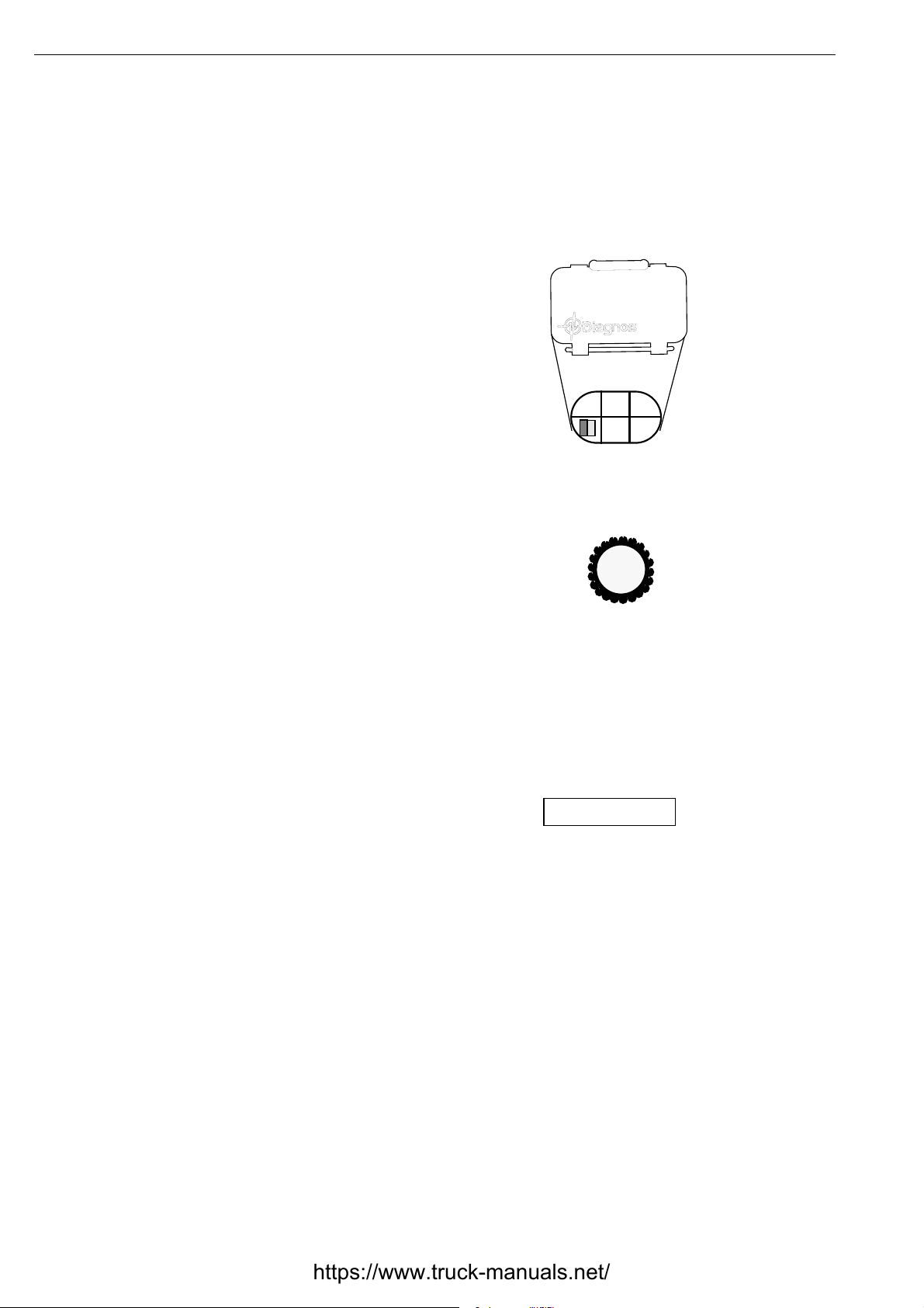
05_5161
The symbols for the various switches are on the
inside of the lid. These can be seen when the lid
is opened. The Opticruise symbol is shown to
the right.
When the warning system is reset, all fault
codes are erased. Proceed as follows:
1 Switch off the power using the starter key.
2 Press the diagnostic switch and hold it
down. Switch on the power.
3 The buzzer gives a short signal. When the
text ”ERASED” is displayed, erasure is
complete.
ERASED!
18
©
Scania CV AB 1995 05:05-02 en
Page 19

Fault codes
General
The control unit acts fast and accurately, according to certain
instructions. It has no imagination and no judgement. When it discovers a fault, or anything it interprets as abnormal, it reacts
immediately and generates fault codes. The warning system is
capable of generating around 70 different fault codes.
Fault codes
Despite the advanced and ”farsighted” software, a fault can arise which the control unit is
unable to distinguish from something which
might happen during normal operation. If this
is the case, no fault code is generated. There is
always a limit to how complete monitoring can
be. This applies to all types of control unit.
Limitations
It is not only ”genuine” faults that lead to the
generation of fault codes. It is sufficient that
someone has unplugged a cable while the
power was on. This can easily happen and the
control unit will then believe that a fault has
arisen.
As for cases of loose contact, the fault may no
longer be present, but the fault code is stored in
the control unit memory until it is erased. It is
at least possible then to see which circuit the
fault was in and look for the cause there, even
if there is currently no fault.
Faults that do not generate fault codes
The following are the faults which do not cause
a fault code to be generated that we are aware
of at the time of going to press.
• Fuse 5 blown (15 supply).
• Break in the diagnostics switch circuit.
• Break in the floor switch circuit.
• Break or continuous signal from program
selector (Normal/Hill).
• Break in circuit to the exhaust brake control
unit. Fault code 14 is generated in some, but
not all, cases.
• Break to gear indicator.
• Broken lamp in gear indicator.
05:05-02 en
©
Scania CV AB 1995 19
Page 20

Fault codes
Explanations
Several new terms are used in the fault code
list or in the connection diagram in group 16.
These terms are explained below.
EEPROM: Stands for electrically erasable
programmable read only memory. Memory is
retained, even if power is broken using the
starter key. The contents can be erased and
updated during service, using a PC and Scania
Programmer.
This memory contains the control unit configuration, programmed starting gear, any fault
codes etc.
FLASH memory: This memory contains the
complete basic programming of the control
unit. The content remains, even if power is
switched off using the starter key. The basic
program can be changed during service using a
PC connected to the diagnostic socket.
RAM: Stands for random access memory. The
content disappears every time the power is
switched off using the starter key or if power is
lost for any other reason.
This memory stores and processes the various
control unit driving data from such things as
sensors, controls and adjacent systems (EDC,
ABS and the retarder).
CAN: Stands for controller area network. CAN
communication is used to reduce the number of
cables in the vehicle. This is intended to
increase reliability.
Vehicles with Opticruise have a communications circuit consisting of two cables, CAN
high (pin 38) and CAN low (pin 20).
In simple terms, CAN communication can be
likened to radio technology. Data signals
through a CAN cable can be likened to radio
waves through the air.
When listening to the radio, the receiver is set
so that one radio station is heard at one time.
This is the only station that can be heard,
despite the fact that there are many radio stations broadcasting at the same time.
A control unit does more or less the same thing
with the data coming through a CAN cable. It
listens for things such as information from
EDC on coolant temperature, receives this
value and uses it in calculations.
The control unit receives all CAN signals that
are sent through the communications circuit in
a special memory. This memory can be likened
to a number of radio receivers, set to different
radio stations in order to hear several, particular radio programmes at the same time. In this
way, the control unit always knows what is
happening.
This is nothing that a mechanic needs to worry
about.
The only thing to remember is that it is
not possible to check CAN signals using a multimeter. This is not even necessary as we have
precise fault codes.
20
©
Scania CV AB 1995 05:05-02 en
Page 21

Fault codes
Fault code 1
Fault code 2
Fault: Fault in integrated control unit memory.
Cause: Test calculation of content of FLASH memory did not
provide the result the control unit was expecting.
Comment: FLASH memory itself contains basic control
unit program. The control unit checks that the FLASH memory is working as follows. All memory addresses are added
together to provide a sum. This sum is then used in a test calculation which must provide the ”correct answer”. Otherwise,
this fault code is generated.
Action: Change control unit.
Fault: Fault in integrated control unit memory.
Cause: Test calculation of content of EEPROM memory did
not provide the result expected by the control unit.
Comment: EEPROM memory contains the configuration of
the control unit. Configuration controls which parts of the
basic program are used for the particular vehicle. When the
control unit checks that the EEPROM memory is working, the
following happens. All values that are important for configuration are added up to a sum. This sum is then used in a test
calculation which must provide the ”correct answer”. Otherwise, this fault code is generated.
Fault code 3
Action: Correctly configure the control unit using a PC. If
this does not help, change the control unit.
Fault: Fault in integrated control unit memory.
Cause: The control unit’s test of the RAM has shown that
some of the memory cells are not working properly.
Comment: The RAM is the actual working memory of the
control unit. It is here that all calculations are made.
When the control unit checks that the RAM is working prop-
erly, the following happens. Firstly, the control unit writes
certain values into the RAM and then reads these same values
to check that they have not become confused . If the control
unit interprets any deviation, this fault code is generated.
Action: Change control unit.
05:05-02 en
©
Scania CV AB 1995 21
Page 22

Fault codes
Fault code 4
Fault: Break or short in circuit for UX supply.
Cause: Control unit has detected that power consumption
from pin 36 on the control unit (the so-called UX feed, +24V)
is either too low or too high.
Comment: The control unit gives UX supply on pin 36 to
supply the sensors, controls and display with power. The UX
supply enables the control unit to sense both open and short
circuits as they cause abnormal power consumption. It is this
abnormal power consumption from pin 36 which causes fault
code 4 to be generated.
Open circuit: The circuit consumes no current. Short circuit:
The circuit consumes high current.
In order for the fault code to be regenerated, power consumption must suddenly change, due to something such as loose
contact. If the fault remains, the fault code is regenerated each
time the control unit attempts to activate the UX supply.
Fault code 5
High current in the UX circuit can be caused by such things as
shorted sensors.
Action: Check the UX circuit, wiring and components.
Fault: Fault in voltage supply in control unit.
Cause: Control unit could not confirm its own internal U15
supply when the driver switched on the power using the
starter key.
Comment: The control unit started working when the power
was switched on, despite it not being possible to confirm U15
supply in the test circuit monitoring this.
When this fault arises, it is not possible for the EEPROM to
store new information. This means that the control unit ”forgets” any newly-programmed starting gear, and any newlygenerated fault codes. The number of faults is displayed as 1,
even if there are several. It is possible to drive the vehicle, but
it should be repaired as soon as possible as certain safety features may be jeopardized.
22
Action: Change control unit.
©
Scania CV AB 1995 05:05-02 en
Page 23

Fault code 7
Fault codes
Fault: Fault in monitoring feature inside control unit.
Cause: The integrated watchdog relay does not activate when
the control unit starts working, or this relay is already activated when the driver switches on the starter power (this
should not be the case).
Comment: The control unit has detected a malfunction in one
of its internal safety features. Each malfunction of this type
causes the watchdog relay to alarm, generating fault code 7.
If the watchdog relay does not activate, power supply is lost to
all control unit outputs. Not even the starter gear can be
engaged, making the vehicle unusable.
Action: Change control unit.
Fault code 14
Fault: Not possible to regulate engine speed to correct level
when changing gear.
Cause: The control unit has received a message from the
EDC via the communications circuit (pins 20 and 38) which
indicated an incorrect response from the engine. The exhaust
brake may have been activated during gear changing without
the Opticruise requesting this.
Comment: Requested torque exceeds permitted value for
engine-controlled gear changing when the gearbox has been
confirmed to be in neutral. This can happen if a gear is
engaged when the control unit is not expecting it. A possible
cause of this might be the slider in the gearbox breaking. If
this fault arises, the driver must use the clutch for every gear
change. CLU_MODE is displayed.
Action: Start by checking the sensor signals for gear position
and then the gearbox itself.
Fault code 15
05:05-02 en
Fault: EDC gives a torque which does not correspond to the
requested torque.
Cause: When the Opticruise control unit requested a particular torque via the communications circuit (pins 20 and 38),
EDC responded with a response which Opticruise considered
to indicate impossible values.
©
Scania CV AB 1995 23
Continued >
Page 24

Fault codes
Comment: Requested torque from Opticruise is ”translated”
in this manner to actual control rack position in the injection
pump. The Opticruise control unit continuously checks that
each response of this type from EDC corresponds with the
expected result. If this fault arises, the driver has to use the
clutch whenever changing gear. CLU_MODE is displayed.
Action: Check whether the EDC control unit has generated
any fault codes. Check that the EDC control unit has the correct part number. Check connectors and wiring. End by
checking the position of the control rack in the injection
pump.
Fault code 19
Fault: NO signal or impossible signal from driving mode
selector.
Cause: The control unit has received a signal on at least two
of pins 10, 11, 28, 29, 47 and 48 at the same time, or there is
no signal at all from the driving mode selector. These signals
are provided with UX voltage (+24V).
Comment: These signals are impossible as the driving mode
selector can only be in one position at a time.
If this fault arises, the control unit does not ”obey” the driving
mode selector. Either there is no signal at all, or the control
unit has received conflicting signals in one of the following
combinations:
Upshift and downshift at the same time (pins 10 and 28).
Reverse and automatic position at the same time (pins 48
and 29).
Reverse and manual position at the same time (pins 48
and 47).
24
Neutral and manual position at the same time (pins 11
and 47).
©
Scania CV AB 1995 05:05-02 en
Continued >
Page 25

Fault code 22
Fault codes
Action: Check the driving mode selector, connectors and wiring. Use wiring diagrams and a multimeter to check the driving mode selector.
Fault: Impossible signals from clutch switches.
Cause: Control unit has sensed that pin 8 received a signal
when there was no signal on pin 45.
Comment: The lower clutch pedal switch has been closed
despite the upper clutch pedal switch not being closed. It
should not be possible for something like this to happen when
driving.
When these switches are activated, they are closed to system
earth (0V).
Fault code 23
The gearbox cannot change gear automatically if this fault has
arisen. The vehicle can, however, be operated using the LIMPHOME emergency gear changing program.
Action: Check both clutch pedal switches, connectors and
wiring.
Fault: Uninterrupted signal from the lower clutch pedal
switch.
Cause: Control unit has sensed that there was a signal for too
long on pin 8.
Comment: The clutch pedal switch cannot be closed for this
long when driving normally.
When this switch is activated, it is closed to system earth
(0V).
The gearbox cannot change gear automatically if this fault has
arisen. The vehicle can, however, be operated using the LIMPHOME emergency gear changing program.
05:05-02 en
Action: Check the lower clutch pedal switch, connectors and
wiring.
©
Scania CV AB 1995 25
Page 26

Fault codes
Fault code 24
Fault: Uninterrupted signal from upper clutch pedal switch.
Cause: Control unit has sensed that the signal remained for
too long on pin 45.
Comment: The clutch pedal switch cannot be closed for this
long when driving normally, unless the driver rests his foot on
the clutch pedal when driving.
When this switch is activated, it is closed to system earth
(0V).
The gearbox cannot carry out engine-controlled gear changing
in manual position if this fault arises.
Action: Check the upper clutch pedal switch, connectors and
wiring.
Fault code 26
Fault: Uninterrupted signal from floor switch for engine
brake program.
Cause: Control unit has sensed that the signal remained for
too long on pin 27.
Comment: The floor switch cannot be closed for this long
during normal driving.
When this switch is activated, it is closed to +24V. Note that
the signal to pin 27 does not always come from the floor
switch. The retarder control unit can also send the same signal.
If this fault arises, the control unit is forced to use the engine
brake program.
Action: Check the floor switch, connectors and wiring. Check
if there are any fault codes stored in the retarder control unit
(if the vehicle has a retarder).
26
©
Scania CV AB 1995 05:05-02 en
Page 27

Fault code 27
Fault codes
Fault: Uninterrupted signal from diagnostic switch.
Cause: Control unit has sensed that the signal remained for
too long on pin 30.
Comment: It is not possible for the diagnostic switch to be
depressed this long during normal use.
When this switch is activated, it is closed to system earth
(0V).
If this fault arises when the driver switches on the power, all
fault codes that can be shown on the display will be erased. It
may also be impossible to start the test program.
Action: Check the diagnostic switch, connectors and wiring.
Fault code 28
Fault: Impossible deviation, vehicle speed compared to tachograph.
Cause: The control unit has sensed that the difference in frequency between the signals to pins 31 and 49 (which together
generate a frequency in the control unit) and the signal to pin
32 is too great.
Comment: The difference between the signal from the inductive speed sensor on the gearbox output shaft and the tachograph signal from the combined instrument was greater than
permitted.
Action: Check the road speed sensor on the gearbox output
shaft, the tachograph signal, connectors and wiring.
05:05-02 en
©
Scania CV AB 1995 27
Page 28

Fault codes
Fault code 31
Fault: Defective contact or loss of signal, vehicle speed sensor.
Cause: Control unit has sensed that the signals on pin 31
and/or pin 49 are too uneven.
Comment: Speed signal from the inductive road speed sensor
on the gearbox output shaft has varied more than permitted.
Speed must exceed a certain limit for the control unit to register this fault.
Action: Check the road speed sensor on the gearbox output
shaft, connectors and wiring.
Fault code 34
Fault code 36
Fault: Break or short circuit, vehicle speed sensor.
Cause: Power consumption too low or too high on pin 31
and/or 49.
Comment: This fault can either be due to a break in the wir-
ing or in the actual sensor, or to a cable being shorted to chassis earth or +24V. In this case, the control unit cannot feel that
the sensor in question is connected.
Action: Check the road speed sensor on the gearbox output
shaft, connectors and wiring.
Fault: Gear changing movement forward on the left-hand
side commanded but not confirmed.
Cause: No confirmation for forward longitudinal stroke (pin
43) on the left-hand side (pin 42), despite several attempts to
activate the solenoid valves which release the compressed air.
28
Comment: The control unit counts both its own attempts and
those of the driver to change gear.
©
Scania CV AB 1995 05:05-02 en
Continued >
Page 29

Fault code 37
Fault codes
Action: Start by checking the air hoses to the solenoid valves
and that the correct air pressure is reaching the solenoid
valves. Then check that the confirmation signals from the hall
effect sensors are transmitted correctly. Check the solenoid
valves for forward longitudinal stroke and left-hand lateral
stroke, connectors and wiring.
Fault: Gear changing movement backward on left-hand side
ordered but not confirmed.
Cause: No confirmation for rearward longitudinal stroke (pin
6) on left-hand side (pin 42), despite several attempts to activate the solenoid valves which release the compressed air.
Comment: The control unit counts both its own attempts and
those of the driver to change gear.
Fault code 38
Action: Start by checking the air hoses to the solenoid valves
and that the correct air pressure is reaching these solenoid
valves. Then check that the confirmation signals from the hall
effect sensor are transmitted correctly. Check the solenoid
valves for rearward longitudinal stroke and left-hand lateral
stroke, connectors and wiring.
Fault: Gear changing movement forward in centre position
commanded but not confirmed.
Cause: No confirmation for forward longitudinal stroke (pin
43), despite several attempts to activate the solenoid valve
which releases the compressed air.
Comment: The control unit counts both its own attempts and
those of the driver to change gear.
Action: Start by checking the air hoses to the solenoid valves
and that the correct air pressure is getting to the solenoid
valves. Then check that the confirmation signals from the hall
effect sensor are transmitted correctly. Check the solenoid
valve for forward longitudinal stroke, connectors and wiring.
05:05-02 en
©
Scania CV AB 1995 29
Page 30

Fault codes
Fault code 39
Fault: Gear changing movement rearward in centre position
commanded but not confirmed.
Cause: No confirmation for rearward longitudinal stroke
(pin 6), despite several attempts to activate the solenoid valve
which releases the compressed air.
Comment: The control unit counts both its own attempts and
those of the driver to change gear.
Action: Start by checking the air hoses to the solenoid valves
and that the correct air pressure is getting to the solenoid
valves. Then check that the confirmation signals from the hall
effect sensor are transmitted correctly. Check the solenoid
valve for rearward longitudinal stroke, connectors and wiring.
Fault code 40
Fault: Forward gear changing movement on right-hand side
ordered but not confirmed.
Cause: No confirmation for forward longitudinal stroke (pin
43) on right-hand side (pin 24), despite several attempts to
activate the solenoid valves which release the compressed air.
Comment: The control unit counts both its own attempts and
those of the driver to change gear.
Action: Start by checking the air hoses to the solenoid valves
and that the correct air pressure is getting to the solenoid
valves. Then check that the confirmation signals from the hall
effect sensor are transmitted correctly. Check the solenoid
valves for forward longitudinal stroke and right-hand lateral
stroke, connectors and wiring.
30
©
Scania CV AB 1995 05:05-02 en
Page 31

Fault code 41
Fault codes
Fault: Gear changing movement rearward on the right-hand
side commanded but not confirmed.
Cause: No confirmation for rearward longitudinal stroke (pin
6) on right-hand side (pin 24), despite several attempts to activate the solenoid valves which release the compressed air.
Comment: The control unit counts both its own attempts and
those of the driver to change gear.
Action: Start by checking the air hoses to the solenoid valves
and that the correct air pressure is getting to the solenoid
valves. Then check that the confirmation signals from the hall
effect sensor are transmitted correctly. Check the solenoid
valves for rearward longitudinal stroke and right-hand lateral
stroke, connectors and wiring.
Fault code 42
Fault: Gear changing movement to the left commanded but
not confirmed.
Cause: No confirmation for left-hand lateral stroke (pin 42),
despite several attempts to activate the solenoid valve which
releases the compressed air.
Comment: The control unit counts both its own attempts and
those of the driver to change gear.
Action: Start by checking the air hoses to the solenoid valves
and that the correct air pressure is getting to the solenoid
valves. Then check that the confirmation signals from the hall
effect sensor are transmitted correctly. Check the solenoid
valve for left-hand lateral stroke, connectors and wiring.
05:05-02 en
©
Scania CV AB 1995 31
Page 32

Fault codes
Fault code 43
Fault: Gear changing movement to the right commanded but
not confirmed.
Cause: No confirmation for right-hand lateral stroke (pin 24),
despite several attempts to activate the solenoid valve which
releases the compressed air.
Comment: The control unit counts both its own attempts and
those of the driver to change gear.
Action: Start by checking the air hoses to the solenoid valves
and that the correct air pressure is getting to the solenoid
valves. Then check that the confirmation signals from the hall
effect sensor are transmitted correctly. Check the solenoid
valve for right-hand lateral stroke, connectors and wiring.
Fault code 44
Fault: Gear changing movement laterally towards the centre
position requested but not confirmed.
Cause: The control unit has sensed that a confirmation signal
for lateral stroke to the left (pin 42) or a lateral stroke to the
right (pin 24) is still present.
Comment: When the confirmation signal for the lateral neutral position exceeds 10 V and no solenoid valve is activated,
a time count is initiated which then stops when the confirmation signals for lateral stroke are no longer present. This fault
code is generated if the time count is not completed within a
predetermined time.
Action: Start by checking the air lines to the solenoid valves
and check that the correct air pressure is reaching the solenoid
valves. Then check that the confirmation signals from the
Hall-effect sensor are correctly received. Check the venting of
the solenoid valves for left and right-hand lateral stroke, the
return springs, connectors and wiring.
32
©
Scania CV AB 1995 05:05-02 en
Page 33

Fault code 45
Fault codes
Fault: Loss of confirmation, forward stroke.
Cause: Control unit has sensed the sudden loss of confirma-
tion signal on pin 43.
Comment: For the control unit to be able to check if the sig-
nal is lost, a complete gear change must first be completed.
Five seconds after the control unit has received confirmation
of the completed gear change, it starts to sense whether the
confirmation signal continues to be transmitted as it should
be. The control unit checks this until it commands the gearbox
to carry out the next gear change. This fault code is generated
if, for example, the gear is ejected mechanically.
Action: Check the hall effect sensor, connectors and wiring.
Fault code 46
Fault: Loss of confirmation, rearward stroke.
Cause: Control unit has sensed the sudden loss of confirma-
tion signal on pin 6.
Comment: For the control unit to be able to check if the sig-
nal is lost, a complete gear change must first be completed.
Five seconds after the control unit has received confirmation
of the completed gear change, it starts to sense whether the
confirmation signal continues to be transmitted as it should
be. The control unit checks this until it commands the gearbox
to carry out the next gear change. This fault code is generated
if, for example, the gear is ejected mechanically.
Action: Check the hall effect sensor, connectors and wiring.
05:05-02 en
©
Scania CV AB 1995 33
Page 34

Fault codes
Fault code 47
Fault: Loss of confirmation, right-hand lateral stroke.
Cause: Control unit has sensed the sudden loss of confirma-
tion signal on pin 24.
Comment: For the control unit to be able to check if the sig-
nal is lost, a complete gear change must first be completed.
Five seconds after the control unit has received confirmation
of the completed gear change, it starts to sense whether the
confirmation signal continues to be transmitted as it should
be. The control unit checks this until it commands the gearbox
to carry out the next gear change. This fault code is generated
if, for example, the gear is ejected mechanically.
Action: Check the hall effect sensor, connectors and wiring.
Fault code 48
Fault code 49
Fault: Loss of confirmation, left-hand lateral stroke.
Cause: Control unit has sensed the sudden loss of confirma-
tion signal on pin 42.
Comment: For the control unit to be able to check if the sig-
nal is lost, a complete gear change must first be completed.
Five seconds after the control unit has received confirmation
of the completed gear change, it starts to sense whether the
confirmation signal continues to be transmitted as it should
be. The control unit checks this until it commands the gearbox
to carry out the next gear change. This fault code is generated
if, for example, the gear is ejected mechanically.
Action: Check the hall effect sensor, connectors and wiring.
Fault: Loss of confirmation, neutral position.
Cause: Control unit has sensed the sudden loss of confirma-
tion signal on pin 7.
34
©
Scania CV AB 1995 05:05-02 en
Continued >
Page 35

Fault code 50
Fault codes
Comment: For the control unit to be able to check if the signal is lost, a complete gear change must first be completed.
Five seconds after the control unit has received confirmation
of the completed gear change, it starts to sense whether the
confirmation signal continues to be transmitted as it should
be. The control unit checks this until it commands the gearbox
to carry out the next gear change. This fault code is generated
if, for example, the gear is ejected mechanically.
Action: Check the hall effect sensor, connectors and wiring.
Fault: No confirmation, neutral position.
Cause: Control unit has not received confirmation signal on
pin 7 to confirm that the commanded gear change has been
carried out.
Fault code 51
Comment: When the solenoid valve for neutral is activated,
time measurement starts which is interrupted when the confirmation signal for neutral position exceeds 10 V. This fault
code is generated if time measurement is not carried out
within a preset time.
This fault code can only be generated when vehicle speed is
greater than 5 km/h or when the clutch pedal is fully
depressed.
Action: Check control cylinders, solenoid valve for neutral
position, compressed air lines, hall effect sensors, connectors
and wiring.
Fault: Continuous confirmation signal, neutral position.
Cause: Control unit has sensed that the confirmation signal
remained for too long on pin 7.
Comment: Confirmation signal may not remain too long after
the command for forward longitudinal stroke or rearward lateral stroke has been given. This fault code can be generated if
the gearbox is binding, for example in severe cold.
05:05-02 en
Action: Check control cylinders, solenoid valves, compressed
air lines, hall effect sensors, connectors and wiring.
©
Scania CV AB 1995 35
Page 36

Fault codes
Fault code 52
Fault: Impossible confirmation (impossible gear positions).
Cause: Simultaneous confirmation from several gears at the
same time.
Comment: The signals are impossible because the Hall-effect
sensor and the confirmation switches should only be able to
confirm one gear changing movement at a time.
Any of the following confirmations have come at the same
time:
Neutral and forward confirmation (pin 7 and pin 43)
Neutral and rear confirmation (pin 7 and pin 6)
Forward and rear confirmation (pin 43 and pin 6)
Right and left confirmation (pin 24 and pin 42)
Low range and high range confirmation (pin 41 and pin 5)
Fault code 53
Low split and high split confirmation (pin 4 and pin 23).
Action: Check hall effect sensors, confirmation switches,
connectors and wiring.
Fault: Gear changing movement to low range commanded
but not confirmed.
Cause: No signal on pin 41.
Comment: No confirmation for low range, despite several
attempts to activate the solenoid valve which releases compressed air. Each gear changing attempt must take a certain
time in order to be counted.
Action: Check control cylinders, confirmation switches, the
low range solenoid valve, compressed air lines, connectors
and wiring.
36
©
Scania CV AB 1995 05:05-02 en
Page 37

Fault code 54
Fault codes
Fault: Gear changing movement towards high range commanded but not confirmed.
Cause: No signal on pin 5.
Comment: No confirmation for high range, despite several
attempts to activate the solenoid valve which releases compressed air. Each gear changing attempt must take a certain
time in order to be counted.
Action: Check control cylinders, confirmation switches, the
high range solenoid valve, compressed air lines, connectors
and wiring.
Fault code 55
Fault: Gear changing movement towards low split commanded but not confirmed.
Cause: No signal on pin 4.
Comment: No confirmation for low split, despite several
attempts to activate the solenoid valve which releases compressed air. Each gear changing attempt must take a certain
time in order to be counted.
Action: Check control cylinders, confirmation switches, the
low split solenoid valve, compressed air lines, connectors and
wiring.
05:05-02 en
©
Scania CV AB 1995 37
Page 38

Fault codes
Fault code 56
Fault: Gear changing movement to high split commanded but
not confirmed.
Cause: No signal on pin 23.
Comment: No confirmation for high split despite several
attempts to activate the solenoid valve which releases the
compressed air. Each gear changing attempt must take a certain time in order to be counted.
Action: Check control cylinders, confirmation switches, the
high split solenoid valve, compressed air lines, connectors and
wiring.
Fault code 57
Fault: Loss of confirmation, low range.
Cause: The control unit has sensed the sudden loss of confir-
mation signal on pin 41.
Comment: For the control unit to be able to check if the sig-
nal is lost, a complete gear change must first be completed.
Five seconds after the control unit has received confirmation
of the completed gear change, it starts to sense whether the
confirmation signal continues to be transmitted as it should
be. The control unit checks this until it commands the gearbox
to carry out the next gear change. This fault code is generated
if, for example, the gear is ejected mechanically.
Action: Check confirmation switches, connectors and wiring.
38
©
Scania CV AB 1995 05:05-02 en
Page 39

Fault code 58
Fault codes
Fault: Loss of confirmation, high range.
Cause: The control unit has sensed the sudden loss of confir-
mation signal on pin 5.
Comment: For the control unit to be able to check if the sig-
nal is lost, a complete gear change must first be completed.
Five seconds after the control unit has received confirmation
of the completed gear change, it starts to sense whether the
confirmation signal continues to be transmitted as it should
be. The control unit checks this until it commands the gearbox
to carry out the next gear change. This fault code is generated
if, for example, the gear is ejected mechanically.
Action: Check confirmation switches, connectors and wiring.
Fault code 59
Fault: Loss of confirmation, low split.
Cause: The control unit has sensed the sudden loss of confir-
mation signal on pin 4.
Comment: For the control unit to be able to check if the sig-
nal is lost, a complete gear change must first be completed.
Five seconds after the control unit has received confirmation
of the completed gear change, it starts to sense whether the
confirmation signal continues to be transmitted as it should
be. The control unit checks this until it commands the gearbox
to carry out the next gear change. This fault code is generated
if, for example, the gear is ejected mechanically.
Action:Check confirmation switches, connectors and wiring.
05:05-02 en
©
Scania CV AB 1995 39
Page 40

Fault codes
Fault code 60
Fault: Loss of confirmation, high split.
Cause: The control unit has sensed the sudden loss of confir-
mation signal on pin 23.
Comment: For the control unit to be able to check if the sig-
nal is lost, a complete gear change must first be completed.
Five seconds after the control unit has received confirmation
of the completed gear change, it starts to sense whether the
confirmation signal continues to be transmitted as it should
be. The control unit checks this until it commands the gearbox
to carry out the next gear change. This fault code is generated
if, for example, the gear is ejected mechanically.
Action: Check confirmation switches, connectors and wiring.
Fault code 61
Fault: Solenoid valve for forward longitudinal stroke is live
when it should not be.
Cause: Control unit output to solenoid valve for forward longitudinal stroke has been powered without the control unit
commanding this.
Comment: This fault code is generated if the control unit output for the solenoid valve in question has been powered for
the wrong reason, for example due to a short circuit to +24
volts (e.g. in wiring). Otherwise, there is a fault in the control
unit itself.
Action: Disconnect the cable from pin 3 and measure using a
multimeter. Then check connectors and wiring.
40
©
Scania CV AB 1995 05:05-02 en
Page 41

Fault code 62
Fault codes
Fault: Solenoid valve for rearward longitudinal stroke is
powered when it should not be.
Cause: Control unit output to solenoid valve for rearward longitudinal stroke has been powered despite the fact that control
unit has not commanded this.
Comment: This fault code is generated if the control unit output for the solenoid valve in question has been powered for
the wrong reason, for example due to a short circuit to +24
volts (e.g. in wiring). Otherwise, there is a fault in the control
unit itself.
Action: Disconnect the cable from pin 22 and measure using
a multimeter. Then check connectors and wiring.
Fault code 63
Fault: Solenoid valve for neutral position is powered when it
should not be.
Cause: Control unit output to the solenoid valve for neutral
position has been powered despite the control unit not commanding this.
Comment: This fault code is generated if the control unit output for the solenoid valve in question has been powered for
the wrong reason, for example due to a short circuit to +24
volts (e.g. in wiring). Otherwise, there is a fault in the control
unit itself.
Action: Disconnect the cable from pin 40 and measure using
a multimeter. Then check connectors and wiring.
05:05-02 en
©
Scania CV AB 1995 41
Page 42

Fault codes
Fault code 64
Fault: Solenoid valve for low range is powered when it
should not be.
Cause: Control unit output to solenoid valve for low range
has been powered despite the control unit not commanding
this.
Comment: This fault code is generated if the control unit output for the solenoid valve in question has been powered for
the wrong reason, for example due to a short circuit to +24
volts (e.g. in wiring). Otherwise, there is a fault in the control
unit itself.
Action: Disconnect the cable from pin 39 and measure using
a multimeter. Then check connectors and wiring.
Fault code 65
Fault: Break or short in circuit to solenoid valve for forward
longitudinal stroke.
Cause: Power consumption too low or too high from pin 3 on
the control unit.
Comment: When the solenoid valve for forward longitudinal
stroke is activated, the control unit can sense the following
cases. Break:Circuit not consuming any current. Short circuit:Current in circuit too high.
For the fault code to be regenerated, power consumption must
suddenly change, for example due to a defective contact. If
the fault remains, the fault code is regenerated each time the
control unit attempts to activate the solenoid valve in question.
High current can be caused by such things as shorted windings in the solenoid valve coil.
Action: Check the solenoid valve for forward longitudinal
stroke, connectors and wiring.
42
©
Scania CV AB 1995 05:05-02 en
Page 43

Fault code 66
Fault codes
Fault: Break or short in circuit to solenoid valve for rearward
longitudinal stroke.
Cause: Power consumption too low or too high from pin 22
on the control unit.
Comment: When the solenoid valve for rearward longitudinal stroke is activated, the control unit can sense the following
cases. Break: Circuit not consuming any current. Short circuit:
Current in circuit too high.
For the fault code to be regenerated, power consumption must
suddenly change, for example due to a defective contact. If
the fault remains, the fault code is regenerated each time the
control unit attempts to activate the solenoid valve in question.
High current can be caused by such things as shorted windings in the solenoid valve coil.
Fault code 67
Action: Check the solenoid valve for rearward longitudinal
stroke, connectors and wiring.
Fault: Break or short in circuit to solenoid valve for righthand lateral stroke.
Cause: Power consumption too low or too high from pin 17
on the control unit.
Comment: When the solenoid valve for right-hand lateral
stroke is activated, the control unit can sense the following
cases. Break: Circuit not consuming any current. Short circuit:
Current in circuit too high.
For the fault code to be regenerated, power consumption must
suddenly change, for example due to a defective contact. If
the fault remains, the fault code is regenerated each time the
control unit attempts to activate the solenoid valve in question.
05:05-02 en
High current can be caused by such things as shorted windings in the solenoid valve coil.
Action: Check the solenoid valve for right-hand lateral
stroke, connectors and wiring.
©
Scania CV AB 1995 43
Page 44

Fault codes
Fault code 68
Fault: Break or short in circuit to solenoid valve for left-hand
lateral stroke.
Cause: Power consumption too low or too high from pin 53
on the control unit.
Comment: When the solenoid valve for left-hand lateral
stroke is activated, the control unit can sense the following
cases. Break:Circuit not consuming any current. Short circuit:
Current in circuit too high.
For the fault code to be regenerated, power consumption must
suddenly change, for example due to a defective contact. If
the fault remains, the fault code is regenerated each time the
control unit attempts to activate the solenoid valve in question.
High current can be caused by such things as shorted windings in the solenoid valve coil.
Fault code 69
Action: Check the solenoid valve for left-hand lateral stroke,
connectors and wiring.
Fault: Break or short in circuit to solenoid valve for neutral
position.
Cause: Power consumption too low or too high from pin 40
on the control unit.
Comment: When the solenoid valve for neutral position is
activated, the control unit can sense the following cases.
Break:Circuit not consuming any current. Short circuit: Current in circuit too high.
For the fault code to be regenerated, power consumption must
suddenly change, for example due to a defective contact. If
the fault remains, the fault code is regenerated each time the
control unit attempts to activate the solenoid valve in question.
44
High current can be caused by such things as shorted windings in the solenoid valve coil.
Action: Check the solenoid valve for neutral position, connectors and wiring.
©
Scania CV AB 1995 05:05-02 en
Page 45

Fault code 70
Fault codes
Fault: Break or short in circuit to solenoid valve for low
range.
Cause: Power consumption too low or too high from pin 39
on the control unit.
Comment: When the solenoid valve for low range is activated, the control unit can sense the following cases.
Break:Circuit not consuming any current. Short circuit: Current in circuit too high.
For the fault code to be regenerated, power consumption must
suddenly change, for example due to a defective contact. If
the fault remains, the fault code is regenerated each time the
control unit attempts to activate the solenoid valve in question.
High current can be caused by such things as shorted windings in the solenoid valve coil.
Fault code 71
Action: Check the solenoid valve for low range, connectors
and wiring.
Fault: Break or short in circuit to solenoid valve for high
range.
Cause:Power consumption too low or too high from pin 54
on the control unit.
Comment: When the solenoid valve for high range is activated, the control unit can sense the following cases. Break:
Circuit not consuming any current. Short circuit: Current in
circuit too high.
For the fault code to be regenerated, power consumption must
suddenly change, for example due to a defective contact. If
the fault remains, the fault code is regenerated each time the
control unit attempts to activate the solenoid valve in question.
05:05-02 en
High current can be caused by such things as shorted windings in the solenoid valve coil.
Action: Check the solenoid valve for high range, connectors
and wiring.
©
Scania CV AB 1995 45
Page 46

Fault codes
Fault code 72
Fault: Break or short in circuit to solenoid valve for low split.
Cause: Power consumption too low or too high from pin 2 on
the control unit.
Comment: When the solenoid valve for low split is activated,
the control unit can sense the following cases. Break:Circuit
not consuming any current. Short circuit:Current in circuit too
high.
For the fault code to be regenerated, power consumption must
suddenly change, for example due to a defective contact. If
the fault remains, the fault code is regenerated each time the
control unit attempts to activate the solenoid valve in question.
High current can be caused by such things as shorted windings in the solenoid valve coil.
Action: Check the solenoid valve for low split, connectors
and wiring.
Fault code 73
Fault: Break or short in circuit to solenoid valve for high
split.
Cause: Power consumption too low or too high from pin 18
on the control unit.
Comment: When the solenoid valve for high split is activated, the control unit can sense the following cases.
Break:Circuit not consuming any current. Short circuit:Current in circuit too high.
For the fault code to be regenerated, power consumption must
suddenly change, for example due to a defective contact. If
the fault remains, the fault code is regenerated each time the
control unit attempts to activate the solenoid valve in question.
High current can be caused by such things as shorted windings in the solenoid valve coil.
Action: Check the solenoid valve for high split, connectors
and wiring.
46
©
Scania CV AB 1995 05:05-02 en
Page 47

Fault code 75
Fault codes
Fault: Fault in power supply to control unit.
Cause: Control unit has sensed that there was no U30 power
supply when the driver switched off the power with the starter
switch.
Comment: The control unit has been switched off several
times in a row without being able to store its data from the
EEPROM. This may be because the control unit has been
switched off with no U30 supply connected to the control
unit. It may also be due to the control unit having been
exposed to strong disturbance which has caused the integrated
protective features in the control unit to act and restart it
repeatedly.
Action: Check the fuse for U30 supply to the Opticruise control unit, connectors and wiring.
Fault code 76
Fault code 77
Fault: The EDC cannot provide a reliable value for throttle
pedal position.
Cause: The control unit has received a message from EDC
via the communications circuit (pins 20 and 38) which shows
that the value from the throttle pedal sensor potentiometer is
impossible.
Comment: In this case, the communications circuit itself is
probably not faulty. Otherwise, the control unit would have
generated a different fault code (fault code 82 or 83).
Action: Check whether there are any fault codes stored in the
EDC control unit.
Fault: The EDC cannot provide a reliable value for current
engine speed.
Cause: The control unit has received a message from EDC
via the communications circuit (pins 20 and 38) which shows
that the value from the engine speed sensor is impossible.
05:05-02 en
Comment: In this case, the communications circuit itself is
probably not faulty. Otherwise, the control unit would have
generated a different fault code (fault code 82 or 83).
Action: Check whether there are any fault codes stored in the
EDC control unit.
©
Scania CV AB 1995 47
Page 48

Fault codes
Fault code 78
Fault code 79
Fault: The EDC cannot provide a reliable value for current
vehicle speed.
Cause: The control unit has received a message from EDC
via the communications circuit (pins 20 and 38) which shows
that the value of the speed signal is impossible.
Comment: In this case, the communications circuit itself is
probably not faulty. Otherwise, the control unit would have
generated a different fault code (fault code 82 or 83).
Action: Check whether there are any fault codes stored in the
EDC control unit.
Fault: The EDC cannot provide a reliable value for brake
pedal position.
Fault code 80
Cause: The control unit has received a message from EDC
via the communications circuit (pins 20 and 38) which shows
that the value from the brake pedal sensor is impossible.
Comment: In this case, the communications circuit itself is
probably not faulty. Otherwise, the control unit would have
generated a different fault code (fault code 82 or 83).
Action: Check whether there are any fault codes stored in the
EDC control unit.
Fault: The EDC cannot provide a reliable value for coolant
temperature.
Cause: The control unit has received a message from EDC
via the communications circuit (pins 20 and 38) which shows
that the value from the temperature sensor is impossible.
Comment: In this case, the communications circuit itself is
probably not faulty. Otherwise, the control unit would have
generated a different fault code (fault code 82 or 83).
48
Action: Check whether there are any fault codes stored in the
EDC control unit.
©
Scania CV AB 1995 05:05-02 en
Page 49

Fault code 81
Fault codes
Fault: Fault in integrated control unit memory.
Cause: The control unit test of communications circuit mem-
ory has shown that some of the memory cells are not working
properly.
Comment: The memory for the communications circuit is
used as a buffer to store information from adjacent systems
(such as EDC and ABS) and then to sort this information
before it is used by Opticruise. The control unit starts by feeding specific values into the communications memory and then
reads these same values to check that they have not become
confused. If the control unit detects any deviation, this fault
code is generated.
Action: Change control unit.
Fault code 82
Fault code 83
Fault: Fault in communications circuit.
Cause: The control unit has sensed that the signal level in the
communications circuit has been faulty. This indicates an
open or short circuit somewhere beyond pins 20 and 38.
Comment: When the signal level fault has ceased, communication starts to work again with no further action.
Action: Check connectors and wiring. If these are not at fault,
then the control unit is faulty, but there is not much chance of
this.
Fault: No communications signal from EDC control unit.
Cause: There has been an abnormally long delay in the
expected signal from EDC via the communications circuit
(pins 20 and 38).
Comment: The Opticruise control unit continuously receives
information from the EDC control unit and ”realizes” that
communication is working properly. If this information is not
present, fault code 83 is generated.
05:05-02 en
Action: Check to see whether there are any fault codes stored
in the EDC control unit. Check connectors and wiring in the
communications circuit.
©
Scania CV AB 1995 49
Page 50

Fault codes
Fault code 84
Fault: No communications signal from ABS control unit.
Cause: There has been an abnormally long delay in the
expected signal from ABS via the communications circuit
(pins 20 and 38).
Comment: The Opticruise control unit continuously receives
information from the ABS control unit and ”realizes” that
communication is working properly. If this information is not
present, fault code 84 is generated.
Action: Check to see whether there are any fault codes stored
in the ABS control unit. Check connectors and wiring in the
communications circuit.
Fault code 85
Fault: Impossible signal from throttle pedal kick-down
switch.
Cause: Control unit has sensed a signal on pin 44, despite the
throttle pedal not being fully depressed.
Comment: The kick-down switch closes to earth (0V). If a
faulty analog value is received from the throttle pedal sensor,
fault code 76 is generated, but the control unit cannot then
generate fault code 85.
Action: Check whether there are any fault codes stored in the
EDC control unit and if the Opticruise control unit has stored
fault code 76. Check the kick-down switch in the throttle
pedal sensor, connectors and wiring.
50
©
Scania CV AB 1995 05:05-02 en
Page 51

Fault code 86
Fault codes
Fault: Incorrect gear ratio in gearbox.
Cause: The relationship between the speed of the input shaft
and output shaft does not correspond to the gear engaged.
Comment: Input shaft speed is taken from the engine speed
sensor. This means that the clutch must be fully released for
speed comparisons to be made.
This fault code can be generated if the control unit has
received confirmation that the clutch is released, but it is still
slipping. The fault code can also be generated if there are
faulty confirmation signals for gear position.
Action: Check if fault codes for gear positions or road speed
sensors are stored. Check that the control unit is configured
for the correct type of gearbox.
Fault code 87
Fault: Impossible deviation, vehicle speed compared to speed
signal from ABS.
Cause: Control unit has sensed too great a difference in frequency between the signals to pins 31 and 49 (which together
generate a frequency in the control unit) and the signal to pins
20 and 38.
Comment: The difference between the signal from the inductive speed sensor on the gearbox output shaft and the speed
signal from the ABS control unit was greater than permitted.
Action: Check the road speed sensor on the gearbox output
shaft, fault codes in the ABS system, connectors and wiring.
05:05-02 en
©
Scania CV AB 1995 51
Page 52

Fault code 88
Fault code 89
Fault: Impossible deviation, tachograph compared to speed
signal from ABS.
Cause: The control unit has sensed that the difference in frequency between the signals to pin 32 and the signal to pin 20
and 38 was too great.
Comment: The difference between the signal from the tachograph and the speed signal from the ABS control unit was
greater than permitted.
Action: Check the tachograph, fault codes in the ABS system,
connectors and wiring.
Fault: ABS cannot provide a reliable value for vehicle speed.
Cause: The control unit has received a message from ABS via
the communications circuit (pins 20 and 38) that shows that
the speed value is impossible.
Comment: In this case, the fault is unlikely to lie with the
communications circuit. Otherwise, the control unit should
have generated another code (fault code 82 or 84).
Action: Check whether there are any fault codes stored in the
ABS control unit.
52
©
Scania CV AB 1995 05:05-02 en
Page 53

Electrical system
References to wiring diagrams
At the time of going to press, no wiring diagrams for the particular fault codes have been produced. We therefore refer to the
connection diagram in Group 16 of the Workshop Manual.
Connection diagram
Electrical system
Publication number: 16:04-21.
Circuit diagrams
Publication number: No information.
Control unit configuration
Configuration is briefly covered on page 11.
Location of electrical components.
See overleaf.
05:05-02 en
©
Scania CV AB 1995 53
Page 54

Electrical system
Location of electrical
components
Item Function
B16 Reversing lights
B25 Throttle actuation
1
(included in D35)
B26 Kick-down (included in D35)
B27 Clutch pedal fully depressed
B41 Confirmation, high range
B42 Confirmation, low range
B43 Confirmation, high split
B44 Confirmation, low split
B49 Exhaust brake and engine brake program
C46-
C401
Connector
D18 Diode unit for EDC
D35 Throttle pedal sensor
E5 Control unit, Opticruise
E6 Hall effect sensor
E12 Control unit, EDC
F2 Fuse holder
G4 Earth connection, instrument panel
G8 Earth connection, instrument panel
G13 Earth connection, connector panel
G18 Earth connection, connector panel
O1 Instrument cluster
O4 Tachograph
P2 Central electric unit
S17 Exhaust brake (on instrument panel)
S30 Power take-off,EG
(S31) Power take-off, EK/ED
S88 Diagnostics switch
S100 Program selector
S101 Driving mode selector
T17 Speed sensor, output shaft
T20 Speed sensor, for tachograph
V13 Solenoid valve, EG power take-off
V20 Solenoid valve, right lateral stroke
V21 Solenoid valve, left lateral stroke
V22 Solenoid valve, neutral position
V23 Solenoid valve, rearward longitudinal stroke
V24 Solenoid valve, forward longitudinal stroke
V62 Solenoid valve, low split
V63 Solenoid valve, low range
V77 Solenoid valve, high split
V78 Solenoid valve, high range
54
1. This switch is not used for the actual Opticruise system.
It closes at the start of throttle pedal travel.
©
Scania CV AB 1995 05:05-02 en
Page 55

05:05-02 en
©
Scania CV AB 1995 55
This figure applies to both LHD and RHD vehicles and covers all
affected optional equipment. Vehicles with less optional equipment
are covered where appropriate.
100917
Electrical system
Page 56

56
Input signals
Function Source Signal type Pin
Confirmation of low split Confirmation switch, split +24V UX 4
Confirmation of high range Confirmation switch, range +24V UX 5
Electrical system
Input signals
The tables on this spread show which input signals the control unit can receive.
©
Scania CV AB 1995 05:05-02 en
Confirmation of rearward longitudinal
stroke
Confirmation of neutral position Hall effect sensor +18V (supplied from UX)
Gives clutch pedal position Lower pedal switch Earthing (0V) 8
Shows whether EK/ED power take-off
is activated
Request for upshift Driving mode selector +24V UX
Request for neutral position Driving mode selector +24V UX 11
Activation of ”Hill” program Program selector +24V UX 12
Confirmation of high split Confirmation switch, split +24V UX 23
Confirmation of right-hand lateral
stroke
Activates engine brake program Retarder control unit or floor switch +24V
To request down shift Driving mode selector +24V UX 28
To request automatic position Driving mode selector +24V UX 29
Hall effect sensor +18V (supplied from UX) 6
7
Switch +24V 9
10
Hall effect sensor +18V (supplied from UX) 24
27
Page 57

05:05-02 en
Input signals, contd.
Function Source Signal type Pin
To activate the test program Diagnostics switch Earthing (0V) 30
Gives vehicle speed Sensor on output shaft Frequency 31
Gives vehicle speed Tachograph Frequency 32
©
Scania CV AB 1995 57
Confirmation, low range Confirmation switch, range +24V UX 41
Confirms left-hand lateral stroke Hall effect sensor +18V (supplied from UX) 42
Confirms forward longitudinal stroke Hall effect sensor +18V (supplied from UX) 43
To request kick-down Kick-down switch Earthing (0V) 44
Gives clutch pedal position Upper pedal switch Earthing (0V)
45
To request manual position Driving mode selector +24V UX 47
To request reverse position Driving mode selector +24V UX 48
Gives vehicle speed Sensor on output shaft Frequency 49
Shows whether EG power take-off is
Switch +24V 50
activated
Stated readings can vary due to a number of factors such as battery voltage
level, length of cables and the condition of cables and contacts.
Electrical system
Page 58

58
Output signals
Function Destination Signal type Pin
To request low split Solenoid valve, low split +24V 2
Electrical system
Output signals
The table below shows which output signals the control unit can supply.
©
Scania CV AB 1995 05:05-02 en
To request forward longitudinal stroke Solenoid valve, forward longitudi-
nal stroke
Gives vehicle speed Retarder control unit via C56 Frequency (+24V)
To request right-hand lateral stroke Solenoid valve, right-hand lateral
stroke
To request high split Solenoid valve, high split +24V
To request rearward longitudinal stroke Solenoid valve, rearward longitudi-
nal stroke
To activate buzzer Buzzer Earthing (0V)
Provides power supply Sensor, controls, display +24V 36
To request low range Solenoid valve, low range +24V 39
To request neutral position Neutral solenoid valve +24V 40
To request activation or disconnection
of exhaust brake
To request left-hand lateral stroke Solenoid valve, left-hand lateral
Exhaust brake control unit PWM Signal 52
stroke
+24V 3
14
+24V 17
18
+24V 22
33
+24V
53
To request high range Solenoid valve, high range +24V
54
Page 59

05:05-02 en
Other connections
Function Source or destination Signal type Pin
Earth for control unit G13 Earthed (0V) 1
Power supply in From batteries, fuse 41 +24V (U30) 19
Communication EDC, ABS/TC etc Data 20
Communication Diagnostic socket for PC Data 25
Communication Diagnostic socket for PC Data 35
Communication EDC, ABS/TC etc Data 38
Other connections
The table below shows the control unit connections for power supply, system earth, communications
lines etc.
©
Scania CV AB 1995 59
Communication Digital display Data 51
Power supply in Via starter switch, fuse 5 +24V (U15)
55
Electrical system
Page 60

Electrical system
Driving mode selector
-R +
• The figure to the right shows the internal connection of the driving mode selector when in
-N+
neutral position.
• The lower figure shows which contacts are
-A +
closed when the driving mode selector is in
its various positions.
-M+
Position Input pin (UX supply) Output pin
33 43 53 63 73 83 34 44 64 54 74 84
R +
R
N
A
M
+
63
54
53
64
83
84
73
74
43
44
33
-
34
R R
RN
N +
N N
NA
A +
A -
A
60
AM
M +
M -
M
= Connection between each terminal pin
©
Scania CV AB 1995 05:05-02 en
Page 61

Test program
• The vehicle must be stationary and the engine be switched off,
unless otherwise stated in the particular test stage.
• Power should be on (starter key to drive position)
• The test program is controlled using the diagnostic switch, concealed under a cover on the instrument panel.
Test program
The test program consists of start, five test stages
and end. The test program only runs in one direc-
FOOTCONT
tion, but can be repeated any number of times. The
diagnostic switch is used to proceed to the next
stage.
The figure to the right shows the gear indicator dis-
TESTING
HANDCONT
GEARENGA
play before each test stage. This is explained in
more detail in the table below.
Various phases of test program
END TEST
ENGINCOM
RPM INFO
Display Intention of test
Various phases of test program
TESTING Test program starts. Presentation of chassis number and control unit part
numbers for hardware and software. Then any fault codes.
FOOTCONT Testing foot controls
HANDCONT Testing hand controls
GEARENGA Testing changing movements and confirmation signals
ENGINCOM Testing engine communication
RPM INFO Testing engine speed sensors and road speed sensors
END TEST Test program ended
05:05-02 en
©
Scania CV AB 1995 61
Page 62

Test program
General
The test program should no be used when driving. Generally, the vehicle should be stationary,
with the engine switched off before testing
starts.
The vehicle may only be driven with the
test program running when this is
demanded in the test instructions. Under
no other circumstances.
If the control unit registers a road speed or
engine speed during testing, the test program is
interrupted. The control unit then returns to normal operation. The intention of this is to avoid
the danger of an unsuitable gear being engaged.
WARNING!
!
END TEST
There are however two test stages which require
the vehicle to be driven and this is when road
speed or engine speed are to be checked. This is
explained in the particular test stages (RPM
INFO and ENGINCOM).
Text in display
For each test stage, a ”heading” is shown in the
display. At the same time, the buzzer gives a
short signal. This reduces the danger of confusing the various test stages.
FOOTCONT
HANDCONT
GEARENGA
ENGINCOMRPM INFO
62
As the gear indicator display is limited to a certain size, letters are used as symbols for the various signals etc in the different test stages. These
symbols are explained in each test stage.
©
Scania CV AB 1995 05:05-02 en
EK
Page 63

Test program
TESTING
ECU NO
PROG NO
CHASSNO
Starting the test program
Fault codes are read at the beginning of the Opticruise test
program. This is also described on pages 16 and 17 in this
booklet. Here, the test program is described in full.
1 The vehicle should be stationary with the engine switched
off.
2 Switch on the power with the starter key. Wait for five
seconds and then press the diagnostic switch for at least
half a second. Release it. ”TESTING” appears in the display and the buzzer sounds.
Leave the diagnostic switch for the moment. The test program has now started. All parts of the display light for one
second. The buzzer sounds.
3 ”ECU NO” is displayed, directly followed by the part
number of the control unit hardware.
4 ”PROG NO” is displayed, directly followed by the part
number of the control unit software.
FCODES
E010 003
A
B
5 ”CHASSNO” is displayed, directly followed by the vehi-
cle chassis number.
6 ”F CODES” is displayed, directly followed by any fault
codes stored. More on this below.
• The fault codes are displayed one at a time, with two seconds between them.
• When all stored fault codes have been displayed, the
buzzer sounds briefly. The stored fault codes are then displayed again. This may be repeated any number of times,
so there is no danger if you should lose concentration.
The display can, for example, look like the figure to the
left. A shows the number of the fault code (10 in this case)
and B shows how many times this fault code has been registered (3).
7 Note the fault codes. Proceed to the next test stage. See
next page.
05:05-02 en
©
Scania CV AB 1995 63
Page 64

Test program
FOOTCONT
Foot controls
The gearbox cannot be operated as long as the control unit is
occupied with this test stage.
1 Preconditions:Stationary vehicle, engine switched off and
power on.
2 Press the diagnostic switch for at least a half second and
release it. ”FOOTCONT” is displayed.
3 Test the controls in order. When each letter is displayed,
the particular signal is active. Use the table below for
clarification.
Signal designation
Floor switch for engine brake program (and
E
exhaust brake)
Upper switch for clutch pedal
U
Lower switch for clutch pedal
D
Brake pedal switch
B
Kick-down switch (integrated in throttle pedal sen-
K
sor)
4 When the test has ended, proceed to the next test stage.
64
©
Scania CV AB 1995 05:05-02 en
Page 65

Test program
HANDCONT
R
N
A
Hand controls
The gearbox cannot be operated as long as the control unit is
occupied with this test stage.
1 Preconditions:Stationary vehicle, engine switched off and
power on.
2 Press the diagnostic switch for at least one half second
and release it. ”HANDCONT” is displayed.
3 Test the controls in order. When each letter is displayed,
the particular signal is active. Use the table below for
clarification.
Signal designation
Driving mode selector to reverse position
R
Driving mode selector to neutral position
N
Driving mode selector to automatic position
A
M
D
U
1 / 2 / X
H
Driving mode selector to manual position
M
Driving mode selector to downshift position
D
Driving mode selector to upshift position
U
Program selector for normal driving or for steep
H
uphill slopes
1 = Switch for power take-off (PTO EK/ED)
1
1
2 = Switch for power take-off (PTO EG)
2
X = Both power take-offs activated simultaneously
1
X
1. When the driving mode selector is set for steep uphill slopes,
the letter H should be displayed.
4 When the test has ended,
neutral and proceed to the next test stage.
set the driving mode selector to
05:05-02 en
©
Scania CV AB 1995 65
Page 66

Test program
GEARENGA
WARNING!
!
Engine must be switched off
during testing.
Gear changing movements and confirmation
signals
In this case, we force the solenoid valves which release compressed air for the shift cylinders and read the confirmation
signals. In this way, it is possible to check that each gear
changing cycle works properly.
If there are fault codes stored which indicate loss of or impossible road speed signals, this test stage cannot be used for
safety reasons.
1 Preconditions: Stationary vehicle, engine switched off,
compressed air in air system and power on.
2 Press the diagnostic switch for at least half a second and
then release it. ”GEARENGA” is displayed.
3 Hold the clutch pedal depressed and try the positions of
the driving mode selector in turn. This is described on the
following pages. Use the table below for clarification.
Signal designation
Range gear position is
always displayed on the far
left of the display, as L, H or
X.
rs
Split gear position is always
displayed on the far right of
the display, as L, H or X.
Range confirmation, where L=low range, H=high
r
range and X=both low range and high range at the
same time
Confirmation for left-hand lateral stroke
L
Confirmation for rearward longitudinal stroke
B
Confirmation for neutral position
N
Confirmation for forward longitudinal stroke
F
Confirmation for right-hand lateral stroke
R
Split confirmation, where L=low split, H=high
s
split and X=both low split and high split simultaneously
4 When the test has ended,
tral and proceed to the next test stage.
check that the gearbox is in neu-
66
©
Scania CV AB 1995 05:05-02 en
Page 67

Low split and low range simultaneously
1 Set the driving mode selector as in fig. 1.
Test program
R
2 Check that LNL is displayed.
High split and high range
simultaneously
3 Set the driving mode selector as in fig. 2.
4 Check that HNH is displayed.
N
A
M
1
R
N
A
M
2
Left lateral stroke
5 Set the driving mode selector as in fig. 3.
6 Check that HLNH (or LLNL) is displayed.
Rearward longitudinal stroke on
left-hand side
7 Set driving mode selector as in fig. 4.
8 Check that HLBH (or LLBL) is displayed.
R
N
A
M
3
R
N
A
05:05-02 en
M
4
©
Scania CV AB 1995 67
Page 68

Test program
Forward longitudinal stroke on left-hand
side
R
9 Set driving mode selector as in fig. 5.
10 Check that HLFH (or LLFL) is displayed.
Rearward longitudinal stroke in centre
position
11 Set driving mode selector as in fig. 6.
12 Check that HBH (or LBL) is displayed.
N
A
M
5
R
N
A
M
6
Forward longitudinal stroke in centre
position
(Only applies to GR gearbox, not GRS)
13 Set driving mode selector as in fig. 7.
14 Check that HFH (or LFL) is displayed.
Rearward longitudinal stroke on
left-hand side
15 Set driving mode selector as in fig. 8.
16 Check that HBRH (or LBRL) is displayed.
R
N
A
M
7
R
N
A
M
68
©
Scania CV AB 1995 05:05-02 en
8
Page 69

Forward longitudinal stroke on
right-hand side
Test program
R
17 Set driving mode selector as in fig. 9.
18 Check that HFRH (or LFRL) is displayed.
Neutral position
Neutral position often, but not always, arises in
combination with another confirmation signal.
19 Set driving mode selector as in fig. 10.
20 Check that HLNH (or LLNL) is displayed.
N
A
M
9
R
N
A
M
10
21 Set driving mode selector as in fig. 11.
22 Check that HNH (or LNL) is displayed.
23 Set driving mode selector as in fig. 12.
24 Check that HNRH (or LNRL) is displayed.
R
N
A
M
11
R
N
A
M
05:05-02 en
©
Scania CV AB 1995 69
12
Page 70

Test program
ENGINCOM
Engine communication
In this test stage, we check the kind of data that Opticruise
must have from the EDC system. In this way, it is possible to
check whether sensors, EDC control unit data processing and
the actual communications circuit are working properly.
During this test, the display gives the test result instead of
gear position and the like. In addition, the vehicle can be
driven as normal.
1 Preconditions: Initially stationary vehicle, engine
switched off and power on. The vehicle should be driven
when the actual test stage has been initiated.
2 Press the diagnostic switch for at least one half second
and release it. ”ENGINCOM” is displayed.
3 Start the engine and drive the vehicle. Drive at an even
speed and check that the values displayed seen plausible.
Use the table below for clarification.
Signal designation
gg
Requested throttle
ee
Actual torque
dd
Requested torque
gg
ee
dd
tt
4 When the test has ended, proceed to the next test stage.
Requested throttle as percentage of full throttle (0 99 %)
Actual torque (x 100 Nm)
Requested torque (x 100 Nm)
Engine temperature (0 - 99 ˚C)
70
tt
Engine temperature
©
Scania CV AB 1995 05:05-02 en
Page 71

Test program
RPM INFO
Speed sensors
Here, we check the various speed information which is compared by Opticruise. In this way, it is possible to check that
both sensors and their wiring are working properly.
During this test, the display gives the test result instead of
gear position and the like. In addition, the vehicle can be
driven as normal.
1 Preconditions: The vehicle should be driven when the
actual test stage has been started.
2 Press the diagnostic switch for at least one half second
and release it. ”RPM INFO” is displayed.
3 Drive the vehicle at an even speed and check that the val-
ues displayed seem plausible. Use the table below for
clarification
Signal designation
nn
Engine speed (x 100 rpm)
nn
Engine speed
v_1
Propeller shaft speed
v_2
From tachograph
v_1
v_2
4 When the test has ended, press the diagnostic switch to
end the test program. When this has been done, ”END
TEST” is displayed and the control unit returns to normal
operation.
See pages 16 to 17 for description of any fault messages
which have arisen during test driving.
Propeller shaft speed from sensor on gearbox output shaft (x 10 rpm)
Speed signal from tachograph, recalculated to propeller shaft speed (x 10 rpm)
05:05-02 en
©
Scania CV AB 1995 71
Page 72

72
©
Scania CV AB 1995 05:05-02 en
Page 73

Mechanical work
General
Internally, the gearbox is standard. Its operating system is similar
to the corresponding one for 3 series CAG 2, but with the difference that the stroke damper for Opticruise is now built into the
longitudinal stroke cylinder. The gearshift housing, located on
the top of the gearbox is also changed. The design is more compact than in previous models.
Mechanical work
Hall effect sensor and shift cylinders
Mechanically, Opticruise has no great changes. We therefore
concentrate on changing and setting the hall effect sensor and
changing the shift cylinders. This is described on the following
pages.
Confirmation switches
The four confirmation switches are of the same type; normally
closed. Tightening torque: 20 Nm. Their location is shown in the
figure below, with the gearbox shown viewed from above. On
older gearboxes, B42 is located on the right-hand side. Designations are explained on page 54.
B44
05:05-02 en
B43
©
Scania CV AB 1995 73
B42
100870
B41
Page 74

Mechanical work
Hall effect sensor, adjusting and
replacement
Use the control unit’s integrated test program or
a PC to detect faults in the hall effect sensor, and
to verify that faults have been corrected when a
repair is completed.
Removal
1 Set the driving mode selector to the neutral
position.
2 Detach the air hoses from the longitudinal
stroke cylinders and the lateral stroke cylinders. Unplug the connector to the hall effect
sensor wiring from the sensor housing.
3 Detach the gearshift housing from the gear-
box and place it upside down on the workbench.
ABA = B
4 Detach the sensor housing from the gear-
shift housing.
5 Blow compressed air into the centre air con-
nection on the longitudinal stroke cylinder.
This sets the gear shift shaft to the neutral
position. Check that the stop on the lever is
in the centre of the coulisse as in the figure
above to the right.
Checking and adjusting
6 Remove both the guide pins from guide
plate 99 150 (these are not needed). Fit the
guide plate in the place of the sensor housing. Check that the magnet housing is in the
correct position.
7 When adjusting: Undo the magnet housing
bolts enough to move the housing, but no
further.
Note: The bolts are locked with locking compound, but do not heat the magnet housing. This
may damage the magnet.
74
8 Adjust the position of the magnet housing
using the guide plate. Then lock the bolts
with locking compound 561 029 and screw
then fully down.
Continued >
©
Scania CV AB 1995 05:05-02 en
1 Sensor housing
2 Magnet housing
3 Spring pins
4 Guide plate 99 150
(Figure shows series 3 design)
Page 75

Hall effect sensor, fitting
9 Fit the sensor housing to the gear shift hous-
ing.
Refit the gear shift housing to the gearbox.
Changing the longitudinal stroke
cylinder
The vehicle’s compressed air system must be
pressurized for the longitudinal stroke cylinder
to be set to the correct position before it is
removed.
1 Switch on the power. Set the driving mode
selector to neutral. The longitudinal stroke
cylinder is set to neutral.
Mechanical work
2 Cut the power. Disconnect the three air
hoses from the longitudinal stroke cylinder.
3 Undo the four securing bolts and remove the
cylinder.
4 Fit the new cylinder. Blow compressed air
into the centre connector, setting the cylinder to the neutral position. Make sure that
teeth on the gearshift shaft are engaged in
the centre position.
5 Fit the air hoses.
6 Remove the level plug. Fill with ATF fluid
up to the hole (about 0.27 litres).
7 Switch on the power and check the gear
changing movements using the test program
(test stage ”GEARENGA”).
The longitudinal stroke cylinder can be turned if
extra space is required. If this is done, the compressed air couplings must also be switched.
Hint: Remove the gear selector housing from
the gearbox if turning the cylinder. this makes
the task easier.
05_5336
05:05-02 en
©
Scania CV AB 1995 75
Page 76

Mechanical work
Changing the lateral stroke
cylinder
It is not necessary for the compressed air system
to be pressurized in order to remove the lateral
stroke cylinder.
1 Switch on the power. Set the driving mode
selector to neutral position.
2 Cut the power. Disconnect the hoses from
the lateral stroke cylinder.
3 Undo the securing bolts and remove the cyl-
inder.
4 Lubricate the piston with brake grease, part
No. 319 308.
5 Fit the new cylinder.
6 Fit the air hoses.
7 Switch on the power and check the gear
changing movements using the test program
(test stage ”GEARENGA”).
Location of compressed air
cylinders
• The figure to the right shows which solenoid
valve the various compressed air couplings
belong to.
• The figure applies to standard vehicle versions.
• The longitudinal stroke cylinder can be
turned. This is sometimes necessary to allow
sufficient clearance for e.g. a hydraulic
pump.
V23
V22
V24
05_5334
V20
V21
76
If this is the case, the air lines for V23 and
V24 must be swapped. This allows the longitudinal stroke cylinder to work in the right
direction when it has been turned.
©
Scania CV AB 1995 05:05-02 en
V62
V77
V63
V78
100859
Page 77

Exploded view drawings
Exploded view drawings
This chapter shows the exploded view drawings for the
most important Opticruise components on the gearbox.
Part numbers are given in our spare parts catalogues.
The drawing below shows the location of solenoid
valves for Opticruise. Designations are explained on
page 54. The location of air lines is shown on page 76.
05:05-02 en
V23
V63
V22
V78
V24
V62
V20
V77
V21
PTO
Location of solenoid valves on gearbox. The two
PTO solenoid valves are for the power take-offs.
©
Scania CV AB 1995 77
100860
Page 78

Exploded view drawings
Longitudinal stroke
cylinder
Item Quantity Designation
1 1 Gasket
2 4 Screw
3 1 Housing
4 1 End plate
5 1 Gasket
6 5 Screw
7 2 Spring pin
8 2 Plug
9 2 Gasket
10 1 Piston rod
11 1 Rack
12 2 Retaining ring
13 2 Retaining ring
14 1 Piston rod
15 2 Washer
16 2 Piston
17 4 Retaining ring
18 1 Bearing sleeve
19 1 V-ring
20 2 Bearing
21 1 O-ring
22 2 Piston
23 2 O-ring
24 2 Washer
25 2 Retaining ring
26 2 Seal
27 1 O-ring
28 1 Cylinder cover
29 3 Screw
78
©
Scania CV AB 1995 05:05-02 en
Page 79

Exploded view drawings
Component parts of the longitudinal
stroke cylinder. Part numbers are listed
in our spare parts catalogues.
Remember to swap the compressed air
couplings if it is necessary to turn the
cylinder to increase available space.
100918
05:05-02 en
©
Scania CV AB 1995 79
Page 80

Exploded view drawings
Gear shift housing with
lateral stroke cylinder
Item Quantity Designation
1 4 Bushing
2 1 Retaining ring
3 1 Filter disc for venting
4 1 O-ring
5 1 Sensor housing assembly
6 1 Magnet housing
7 1 O-ring
8 2 Spring pin
9 4 Screw
10 4 Screw
11 1 Gear shift shaft
12 1 Magnet holder
13 1 Screw
14 3 Screw
15 1 Lever
16 2 Screw
17 2 Key
18 2 Spacer
19 1 Coulisse
20 2 Cap
21 4 Screw
22 2 Retaining ring
23 2 Washer
24 1 Spring
25 1 Spacer
26 1 O-ring
27 1 Retaining ring
28 1 V-ring
29 1 Lever
30 1 Cylinder
31 1 Piston
32 1 Spacer
33 1 V-ring
34 1 O-ring
35 1 O-ring
36 1 O-ring
37 1 O-ring
38 2 Screw
39 2 Plug
40 2 Gasket
80
41 1 Housing
42 1 Screw
43 1 Washer
©
Scania CV AB 1995 05:05-02 en
Page 81

Exploded view drawings
05:05-02 en
Component parts of the gear shift housing and lateral stroke cylinder. Part
numbers are listed in our spare parts
catalogues.
©
Scania CV AB 1995 81
Page 82

Exploded view drawings
Compressed air parts
on gearbox
Item Quantity Designation
1 1 Bracket
2 2 Bracket
1
3 3 Holder
4 2 Nut
5 2 Screw
6 2 Screw
7 2 Nut
8 11 Strap
9 22 Screw
10 22 Washer
11 7 Screw
12 7 Nut
13 14 Cone
14 9 Solenoid valve
15 7 O-ring
16 2 Union
17 10 Elbow union
18 5 Elbow union
19 4 Union
20 1 Clip
2
21 1 Screw
22 4 Bracket
23 2 T-union
VAE M
3
Plastic pipe
VAJ -”- Plastic pipe
VAF -”- Plastic pipe
VSR -”- Plastic pipe
VSS -”- Plastic pipe
XBN -”- Plastic pipe
VRH -”- Plastic pipe
VRL -”- Plastic pipe
VCH -”- Plastic pipe
VCL -”- Plastic pipe
VSH -”- Plastic pipe
VSL -”- Plastic pipe
A ERF4Union nut
Ferrule
Insert sleeve
82
1. Drawing shows early version
2. See page 77 for locations
3. M = By the metre
4. ERF = Whatever quantity is required
©
Scania CV AB 1995 05:05-02 en
Page 83

Exploded view drawings
05:05-02 en
Compressed air parts on gearbox. Part
numbers are listed in our spare parts
catalogues.
©
Scania CV AB 1995 83
Page 84

84
©
Scania CV AB 1995 05:05-02 en
 Loading...