

Page 1

Operator's manual
Scania
Instrumentation
en-GB 2 374 015
Issue 2.0
Page 2

Introduction . . . . . . . . . . . . . . . . . . . . . . . . . . . . 3
Overview . . . . . . . . . . . . . . . . . . . . . . . . . . . . . . 3
Analogue instrument panel . . . . . . . . . . . . . . . 5
Analogue instrument panel for engines without
SCR system . . . . . . . . . . . . . . . . . . . . . . . . . . . 5
Analogue instrument panel for engines with SCR
system . . . . . . . . . . . . . . . . . . . . . . . . . . . . . . . 6
Display in tachometer . . . . . . . . . . . . . . . . . . . 7
Control panel . . . . . . . . . . . . . . . . . . . . . . . . . . 10
Starter lock . . . . . . . . . . . . . . . . . . . . . . . . . . 10
Engine speed setting 1 and 2. . . . . . . . . . . . . 11
Idling speed adjustment . . . . . . . . . . . . . . . . 12
Limp home mode . . . . . . . . . . . . . . . . . . . . . 12
Remote control . . . . . . . . . . . . . . . . . . . . . . . . . 13
Digital display . . . . . . . . . . . . . . . . . . . . . . . . . 14
Function . . . . . . . . . . . . . . . . . . . . . . . . . . . . 14
Display structure . . . . . . . . . . . . . . . . . . . . . . 15
Favourite screens. . . . . . . . . . . . . . . . . . . . . . 16
Information (4) . . . . . . . . . . . . . . . . . . . . . . . . . 19
Statistics trip (4.1) . . . . . . . . . . . . . . . . . . . . . 19
Performance (4.2) . . . . . . . . . . . . . . . . . . . . . 19
Fault codes (5). . . . . . . . . . . . . . . . . . . . . . . . . . 21
Information about the highlighted fault code 22
Clear fault codes . . . . . . . . . . . . . . . . . . . . . . 22
Update the fault code list . . . . . . . . . . . . . . . 23
Settings (6). . . . . . . . . . . . . . . . . . . . . . . . . . . . . 23
Contrast/brightness (6.1). . . . . . . . . . . . . . . . 23
Button beep (6.2). . . . . . . . . . . . . . . . . . . . . . 24
Language (6.3) . . . . . . . . . . . . . . . . . . . . . . . 24
Units (6.4) . . . . . . . . . . . . . . . . . . . . . . . . . . . 25
Engine (6.5). . . . . . . . . . . . . . . . . . . . . . . . . . 26
Examples of setting. . . . . . . . . . . . . . . . . . . . 32
Base system (6.6) . . . . . . . . . . . . . . . . . . . . . 33
Alarm and fault code generation . . . . . . . . . . 33
Alarms. . . . . . . . . . . . . . . . . . . . . . . . . . . . . . 33
External alarm signal . . . . . . . . . . . . . . . . . . 35
Fault code generation . . . . . . . . . . . . . . . . . . 35
OPM 500 en-GB 2
©
Scania CV AB 2014, Sweden
Page 3
Introduction
Note:
321 034
1
2
3
4
5
6
7
8
4
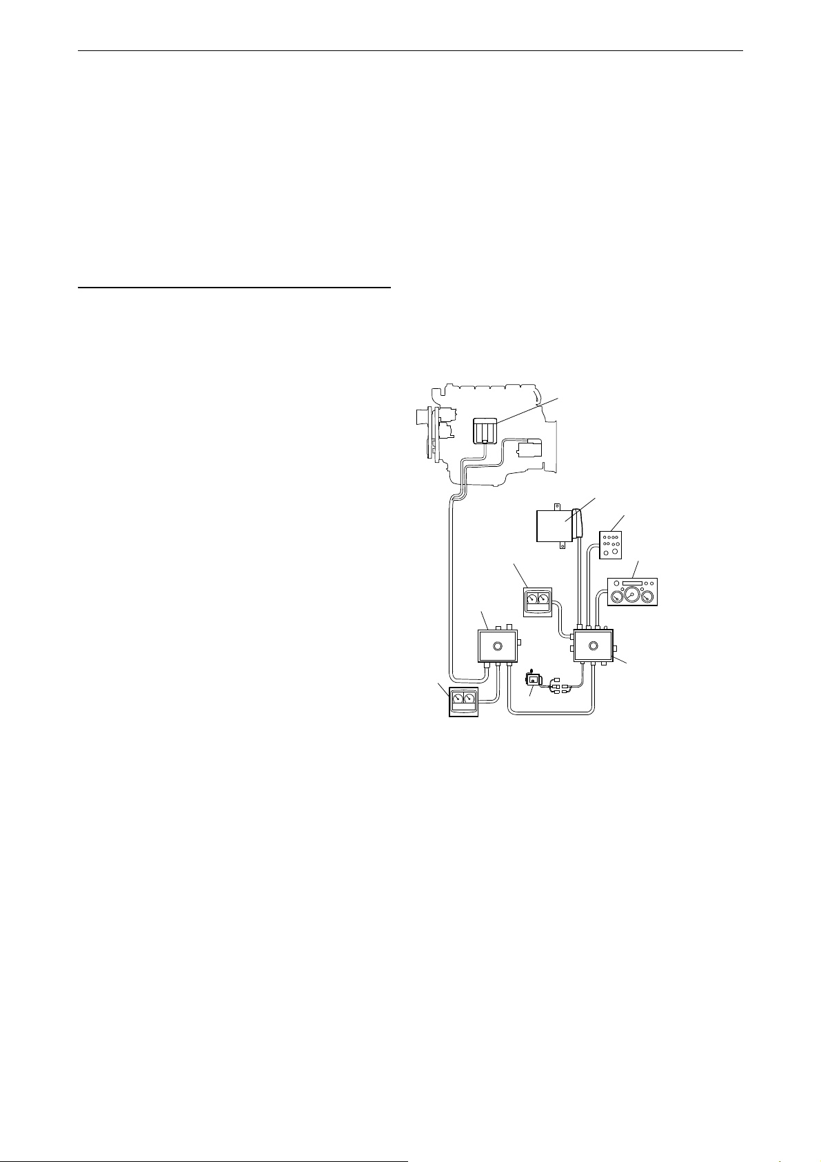
Base system for industrial engines
1. Engine control unit
2. Main junction box
3. Coordinator
4. Digital display
5. Coordinator junction box
6. Control panel
7. Analogue instrument panel
8. Accelerator pedal sensor
This Operator's manual describes operation of
Scania instrumentation.
The information in this manual was correct at the
time of going to press. Scania reserves the right
to make alterations without prior notice.
Always use Scania spare parts for repair work.
Overview
The base system consists of a coordinator, coordinator junction box and main junction box. The
main junction box is connected directly to the engine control unit. There are a number of different
options for the base system that can be connected
to the system:
Introduction
• A digital display together with a control panel
with starter key.
• An analogue instrument panel that can be
used instead of the digital display or together
with it.
• An accelerator pedal sensor.
• A remote control (for marine engines only).
The entire instrumentation system is Plug and
Play which makes it very easy to install.
This Operator's manual only describes the analogue instrument panel, remote control, digital
display and control panel.
OPM 500 en-GB 3
©
Scania CV AB 2014, Sweden
Page 4

Overview
1
2
3
4
5
6
7
8
9
343 188
Base system for marine engines
1. Engine control unit
2. Remote control
3. Main junction box
4. Accelerator pedal sensor
5. Coordinator junction box
6. Analogue instrument panel
7. Control panel
8. Coordinator
9. Digital display
OPM 500 en-GB 4
©
Scania CV AB 2014, Sweden
Page 5
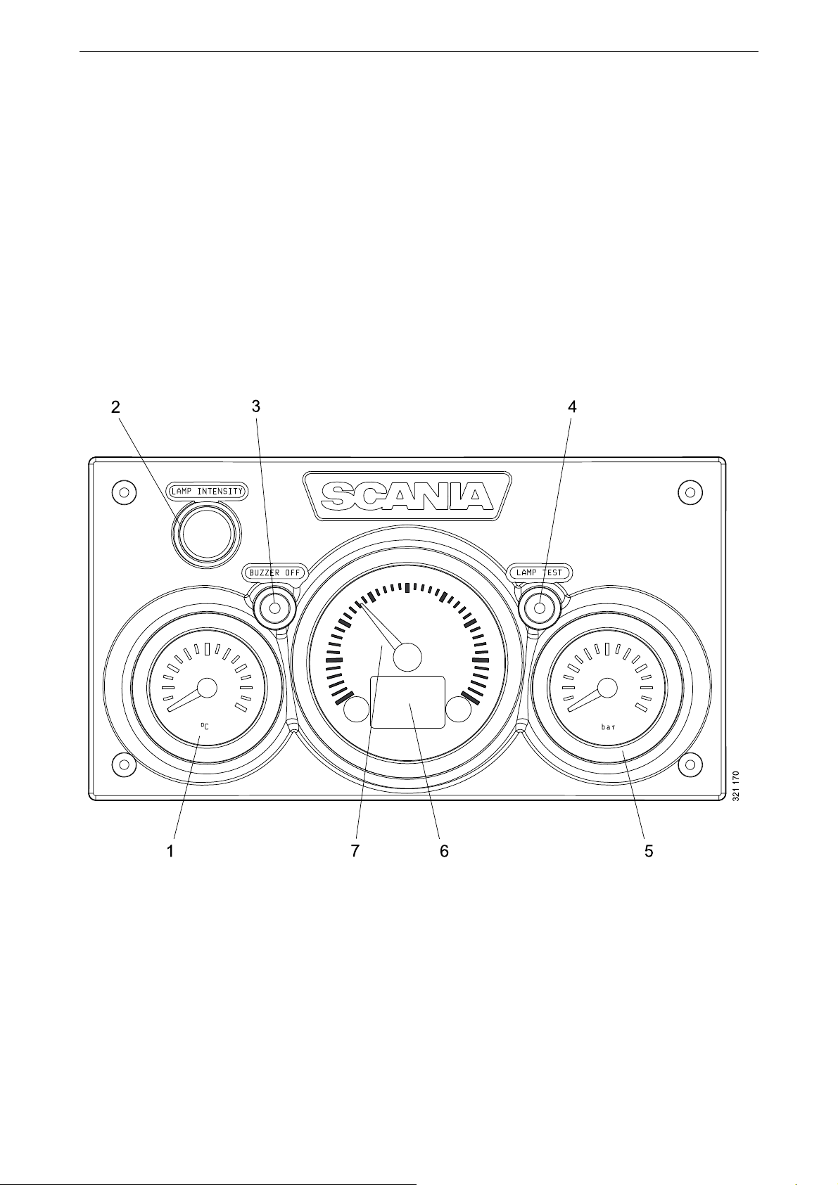
Analogue instrument panel
1. Coolant temperature display
2. Adjusting instrument lighting brightness (Lamp intensity)
3. Buzzer deactivation (Buzzer off)
4. Lamp test (Lamp test)
5. Display for oil pressure
6. Display showing engine data, alarms and fault codes
7. Tachometer
The analogue instrument panel has instruments
for reading engine speed, coolant temperature
and oil pressure. It also has hour counting and diagnostic and alarm switches and lamps.
The analogue instrument panel is available in 2
versions, depending on whether the engine is
equipped with an SCR system or not.
Analogue instrument panel
for engines without SCR system
Analogue instrument panel
OPM 500 en-GB 5
©
Scania CV AB 2014, Sweden
Page 6

Analogue instrument panel
1. Coolant temperature display
2. Adjusting instrument lighting brightness (Lamp intensity)
3. Buzzer deactivation (Buzzer off)
4. Lamp test (Lamp test)
5. Display for oil pressure
6. Display showing engine data, alarms and fault codes
7. Tachometer
8. Warning lamp for low reductant level
9. Warning lamp for SCR system faults.
for engines with SCR system
Analogue instrument panel
OPM 500 en-GB 6
©
Scania CV AB 2014, Sweden
Page 7
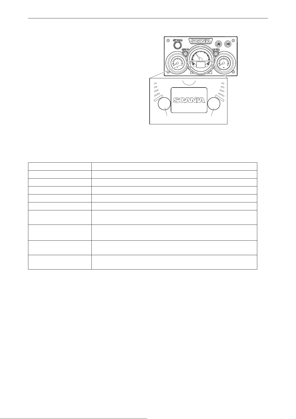
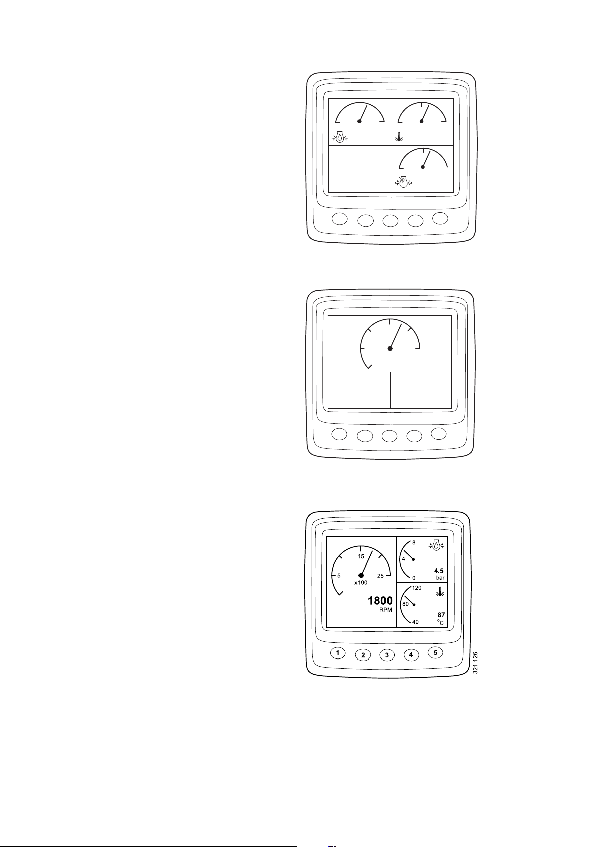
Display in tachometer
322 253
12
Integrated in the tachometer is a digital display
that shows engine data, alarms and fault codes.
Button 1 displays the previous page and button 2
displays the next page. The table below describes
how to go down a level in the structure.
Engine data shown on the display
Analogue instrument panel
Engine data Explanation
Coolant temperature
Oil pressure
Fuel level
Fuel consumption
Charge air pressure
Trip meter
Adjusting instrument lighting brightness
Reset the trip meter by holding buttons 1 and 2 down at the same time for
3 seconds.
Reduce the brightness by holding button 1 down for 3 seconds
Increase the brightness by holding button 2 down for 3 seconds
Settings No settings can be changed. The only available language is English and the
only available unit is metric
Fault codes Display an explanation of active fault codes by holding buttons 1 and 2
down at the same time for 3 seconds.
OPM 500 en-GB 7
©
Scania CV AB 2014, Sweden
Page 8
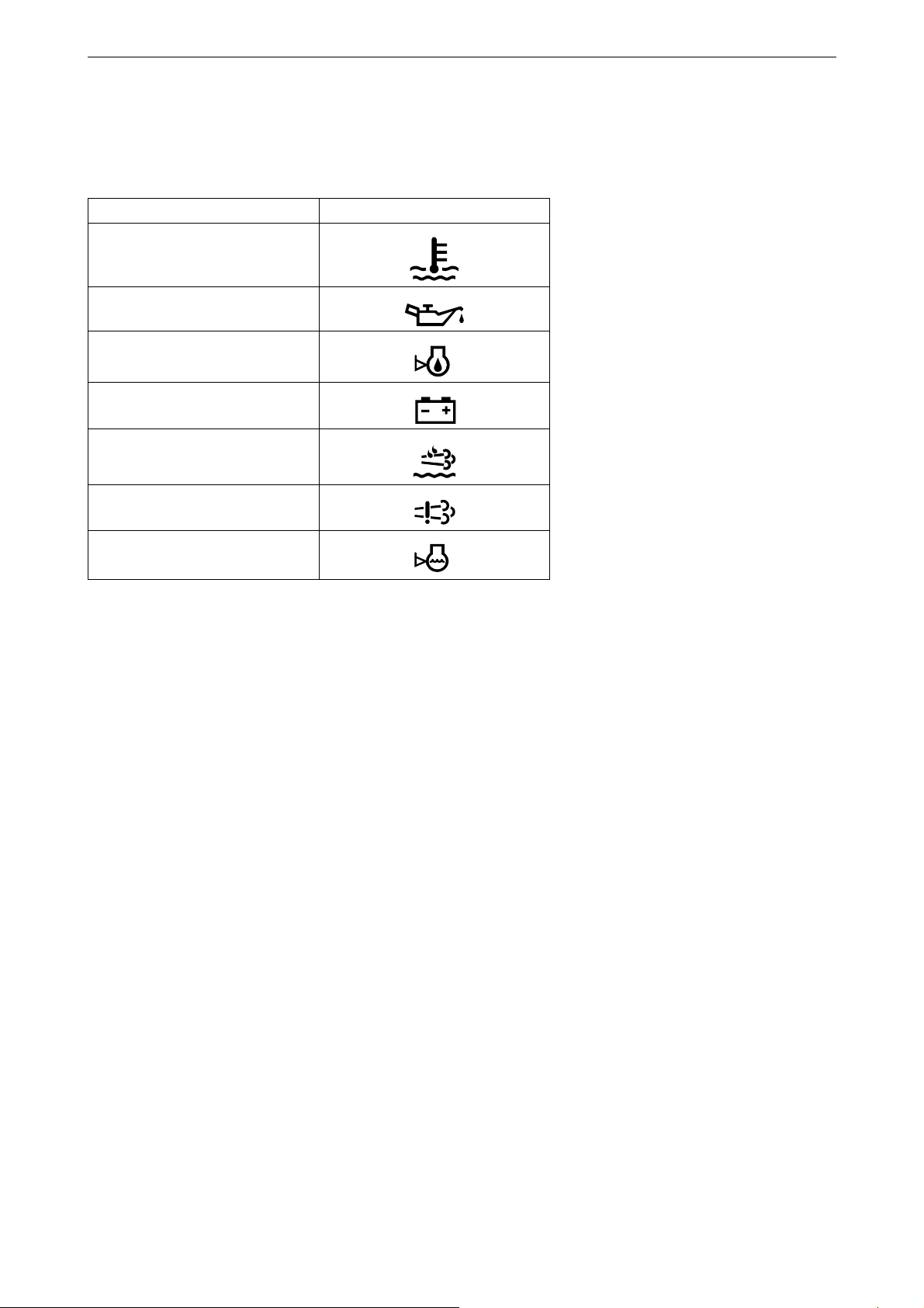
Alarms
On the display in the tachometer, the following
alarms are shown:
Alarm Symbol
High coolant temperature
Low oil pressure
Analogue instrument panel
Oil level too high or low
1
Alternator not charging
Low reductant level
SCR fault
1
Low coolant level
1. Depending on how the engine is equipped.
1
1
OPM 500 en-GB 8
©
Scania CV AB 2014, Sweden
Page 9
Fault codes
343 928
21
322 255
92.2
Coolant [C˚]
322 256
DTC:
EMS
11
1/16
2100!
1
2
3
4
5
6
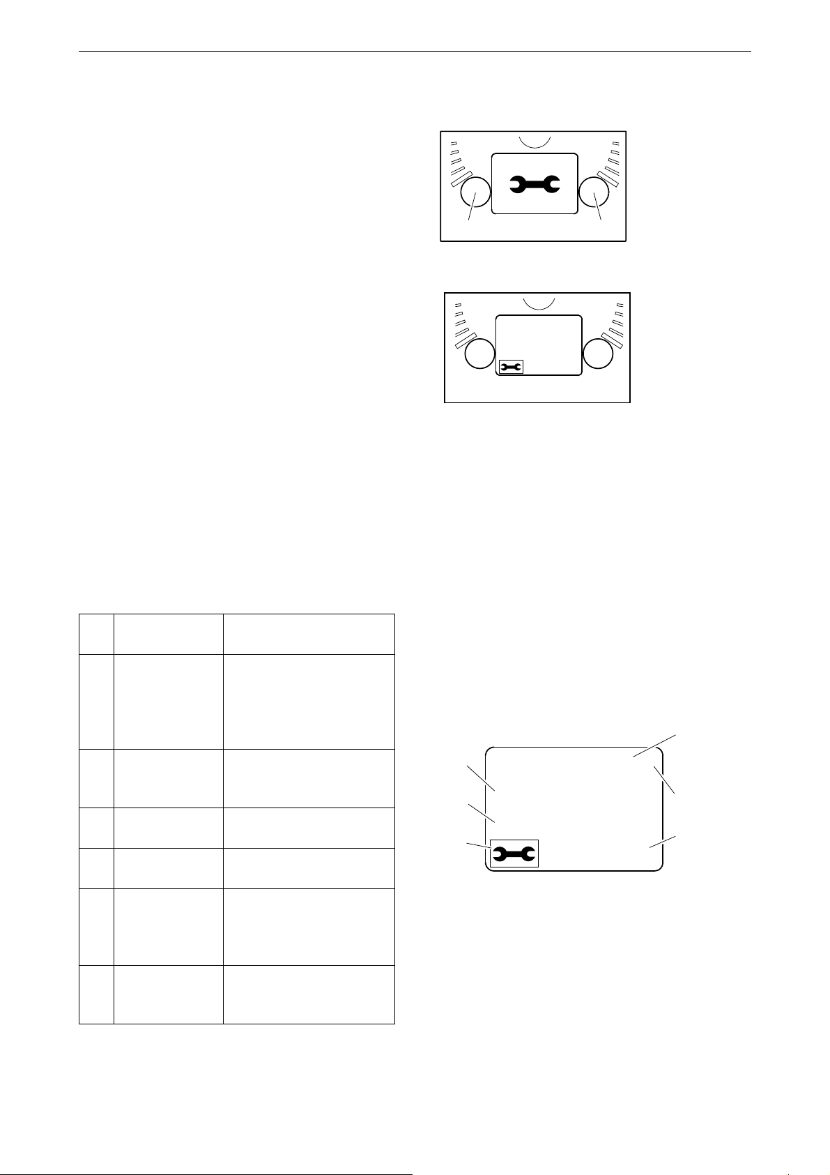
When a fault code is generated, a symbol is
shown on the display in the tachometer. Acknowledge the fault code by pressing button 1 or
2.
Once the fault code has been acknowledged, the
fault code symbol remains (refer to illustration)
as long as the fault code is active.
Analogue instrument panel
Fault code description
If you want to see a more detailed description of
the fault code, hold buttons 1 and 2 down at the
same time for 3 seconds.
The fault code contains the following information:
Pos.Information Explanation
1 Shows the con-
trol unit in
which the fault
code was registered
2 Counter Shows how many times
3 Fault code sym-
bol
4 Fault code Shows the fault code in
5 Active fault
code
6 Page Shows which page is ac-
The engine management
system (EMS), coordinator (COO) or SCR control
unit (SCR)
the displayed fault has occurred
hexadecimal form
! is shown if the fault code
is active. If the fault code
is inactive, no ! is displayed
tive and how many pages
there are
OPM 500 en-GB 9
©
Scania CV AB 2014, Sweden
Page 10

Control panel
23 4 5
19 8
6
7
321 169
The engine is started and shut down from the
control panel, which has a starter lock and functions for engine speed setting and idling setting.
1. Control for adjusting engine speed and idling
speed
2. Control for storing new engine speed and
idling speed
3. Control for activating engine speed setting 1
4. Control for activating engine speed setting 2
5. Control for deactivating engine speed setting
1 (marine engines) or 2 (industrial engines).
6. Indicator lamp for limp home throttle con-
1
trol
7. Limp home throttle control (Limp home)
8. Starter lock
9. Indicator lamp for active panel (Active pan-
el)
1
Control panel
Starter lock
The starter lock (8) is used to start and shut down
the engine.
Position 0: The engine electrical system and the
engine are switched off.
Position 1: The engine electrical system is activated.
Position 2: The starter motor is activated.
1. Only available for marine engines.
OPM 500 en-GB 10
©
Scania CV AB 2014, Sweden
Page 11

Engine speed setting 1 and 2
Note:
23 4 5
19 8
6
7
321 169
Engine speed setting 1 is an engine speed set between high and low idling. High and low idling
vary depending on the engine. The engine speed
is set with control 3.
Engine speed setting 2 is an engine speed that is
set between 450 and 2,000 rpm. The engine
speed is set with control 4.
For both engine speed settings, torque limitation
can be set via either the digital display or using
SDP3. The engine speed settings are isochronous, i.e. the engine speed is held constant irrespective of load.
When either of the engine speed settings is activated, the engine speed goes up or down to the
last saved engine speed.
Control panel
In order to activate engine speed setting 1 or 2,
the engine must be running, the active panel indicator lamp must be on and the throttle must be
at 0%.
Change the engine speed:
• Activate engine speed setting 1 or 2 with control 3 or 4.
• Adjust engine speed up or down with control
1.
• Save the new setting by holding control 2
down for 3 seconds.
If the setting is not saved, the engine uses the last
saved value next time engine speed setting is activated.
This is how to switch off the engine speed settings:
• Press control 5, touch the accelerator pedal or
switch off the engine.
OPM 500 en-GB 11
©
Scania CV AB 2014, Sweden
Page 12

Idling speed adjustment
Note:
23 4 5
19 8
6
7
321 169
Setting range:
Engine type Setting range
XPI engine 600-750 rpm
PDE engine 500-1,300 rpm
Set the engine idling speed:
• Hold control 2 down for 3 seconds. This will
take you to the adjustment mode.
• Adjust idling up or down with control 3.
• Save the new setting by holding control 2
down for 3 seconds.
It is also possible to change engine idling speed
with the digital display or using SDP3.
Control panel
In order to change the idling speed setting, the
coolant temperature must be higher than 50°C
(122°F) with the engine idling.
Limp home mode
Limp home mode is a marine engine function
that is activated if the coordinator or accelerator
pedal fails or if CAN communication is not
working.
If one of these occurs, the indicator lamp for limp
home throttle control 6 and limp home throttle
control 7 is connected.
The limp home throttle consists of a potentiometer on the control panel which can be used to
limp home. The potentiometer value goes directly to connector A2 on the engine control unit.
In order to use the limp home throttle control, the
potentiometer must first be turned to the 0 position and then activated.
OPM 500 en-GB 12
©
Scania CV AB 2014, Sweden
Page 13

Remote control
WARNING!
START
LOCAL
REMOTE
STOP
2
3
1
4
343 187
Remote control
1. Green indicator lamp
2. Starter button
3. Key switch to activate the Local function
4. Stop button
The remote control for marine engines is connected on connector C4044 on the main junction
box. The remote control can be used to lock the
engine so that it cannot be controlled from anywhere other than where the remote control is located.
This can and should only be done when the boat
is moored, i.e. when there is no risk that the boat
will drift out of control. There is a sign on the remote control with this warning text.
There are 2 positions for key switch 3: Local and
Remote.
Remote control
• Local: The engine cannot be controlled from
anywhere other than from the remote control.
• Remote: Normal position, i.e. the engine can
be operated from the other throttle control positions.
When Local mode is activated, the green indicator lamp 1 comes on. At the same time the active
panel indicator lamp on the control panel starts to
flash, which indicates that the control panel cannot be activated.
When the engine is started from the remote control via starter button 2, it only runs at idling
speed whileLocal mode is activated and no other
throttle control can be used.
If the key switch is reset from Local to Remote
when the engine is running, the green indicator
lamp 1 goes out and the engine continues to run
at idling speed. Other control positions can however take command of throttle control, if the control panel is activated. If key switch 3 is reset
from Remote to Local while running, nothing
happens, but this will be regarded as an unintentional action.
If CAN communication fails when the engine
has been started from the remote control, the engine will stop, but the limp home throttle pedal
will not be engaged.
In order to start the engine again, it is necessary
to carry out the following connection:
• Connect pin 50 on the starter relay to the positive pin on the starter motor. The engine
OPM 500 en-GB 13
©
Scania CV AB 2014, Sweden
Page 14

starts but it is only possible to control the
throttle using the limp home throttle control.
In order to switch off the engine you must switch
off the power to the engine control unit by turning the starter key to 0. Alternatively you can
switch off the power via connector C4027 in the
main junction box.
Digital display
The digital display shows engine data and any
alarm systems and fault codes. But the display
can also be used to set certain parameters in the
engine control unit.
Digital display
Function
The information content can be found in different screens according to a tree structure. The are
6 different screens at the top level:
• 3 favourite screens
• Information
• Diagnostics
• Settings
The buttons on the display have different functions depending on which screen is active. Use
buttons 1 and 5 to scroll between the different
screens at the top level, depending on which direction you want to go in the loop.
When one of the favourite screens is active, the
information about each button's function is hidden. The reason for this is to make as big an area
as possible available for presentation. When a
button is pressed, the description of the buttons is
displayed for about 5 seconds. Each window
apart from the favourite screens is numbered at
the top left. The numbering indicates the favourite screen and the level of the structure you are
on.
OPM 500 en-GB 14
©
Scania CV AB 2014, Sweden
Page 15

Display structure
123
Favourite screen (3)
Information
Fault codes
Display modes, levels
Change appearance of Favourite
Change content in window
screen
Statistics trip Display and reset
Performance Display
System data Information
Clear fault codes Acknowledgement
Information on fault code
Update fault code list Acknowledgement
Digital display
Contrast/brightness Adjust
Button beep Change
Language Change
Settings
Units Change
Engine
Base system Change
1. A password is required to change engine settings.
Change engine settings
1
OPM 500 en-GB 15
©
Scania CV AB 2014, Sweden
Page 16
Favourite screens
Favourite screen 1
Favourite screen 2
Favourite screen 3
Digital display
The favourite screens are used to show engine
data during operation. There are 3 different favourite screens which are all at the top level of
the display structure.
4
2
4.5
ENGINE SPEED
1500
RPM
1
2
5
OIL PRESSURE
3.2
bar
84080120
bar
2
0
2.5
4
3
15
25
x100
1800
RPM
COOLANT TEMP
91
o
C
o
87
C
4
bar
5
341 589
1
2
3
5
4
341 590
OPM 500 en-GB 16
©
Scania CV AB 2014, Sweden
Page 17
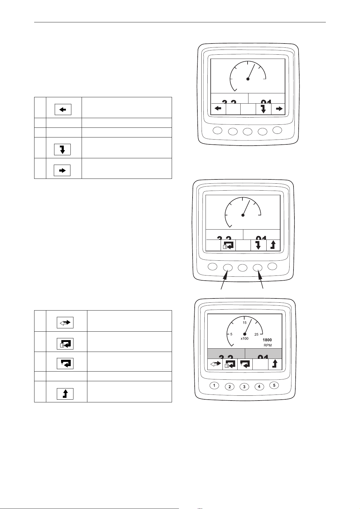
If you want to change from one favourite screen
3
2
1
1
2
7
321 128
3
2
1
1
4
6
321 129
321 130
321 131
321 132
to another favourite screen, press button 1 or 5
depending on which is currently displayed.
In this display mode, the buttons have the following functions:
1 Scroll to the left in the top level
2
3
4 Go down one level in the struc-
ture
5 Scroll to the right in the top level
5
OIL PRESSURE
1
2
15
25
x100
COOLANT TEMP
3
Digital display
1800
RPM
5
4
341 591
Change appearance of Favourite
screen
If you want to change the appearance of a favourite screen, press button 4.
Then press button 2 to change the appearance of
the screen in the sequence on the previous page.
Change content in window
Press button 4 from the change appearance position on the favourite screen to display the button
panel in the table below.
1
2
3
Change between digital and
analogue display
Change active (not greyed)
window
Change content in active (not
greyed) window
5
OIL PRESSURE
1
2
OIL PRESSURE
15
25
x100
COOLANT TEMP
3
COOLANT TEMP
1800
RPM
5
4
341 592
4
5
Go up one level in the structure
OPM 500 en-GB 17
©
Scania CV AB 2014, Sweden
341 593
Page 18
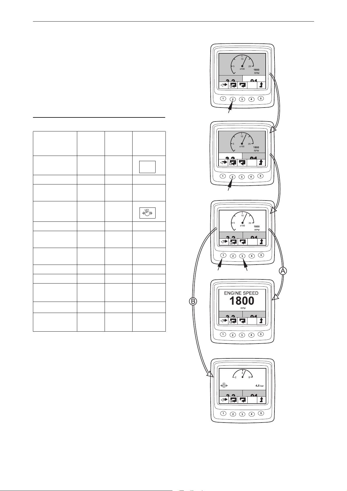
In order to select the contents of a subwindow, it
Note:
OIL PRESSURE
COOLANT TEMP
OIL PRESSURE
COOLANT TEMP
OIL PRESSURE
COOLANT TEMP
OIL PRESSURE
COOLANT TEMP
OIL PRESSURE
COOLANT TEMP
341 594
RPM
321 133
321 134
must be active. Activate a window by pressing
button 2.
The information in the different subwindows can
be displayed in digital or analogue format.
Some information can only be displayed in digital format. Refer to the table.
Digital display
Parameter Digital
display
Analogue
display
Engine speed x x
Oil pressure x x
Coolant tem-
xx
perature
Charge air pres-
xx
sure
System voltage x x
Fuel consump-
x
tion
Load at current
x
engine speed
Operating time x
Throttle x
Oil tempera-
1
ture
Oil level
1
Reductant lev-
1
el
1. Depending on how the engine is ordered.
xx
x
x
Symbol
Switch between analogue and digital display by
pressing button 1 (A).
Change the contents of an activated subwindow
by pressing button 3 (B).
OPM 500 en-GB 18
©
Scania CV AB 2014, Sweden
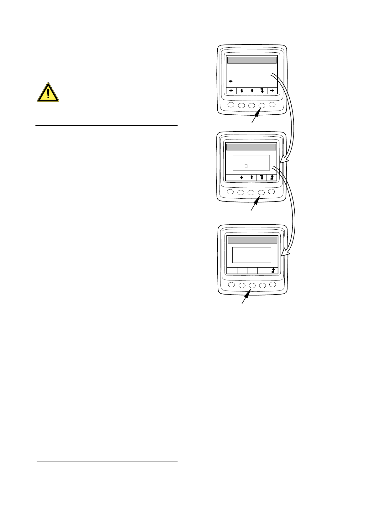
Page 19

Information (4)
Note:
This is how to go to the Information display
mode from a favourite screen:
Press any button to display the button bar on the
screen.
Press button 5 one to three times, depending on
which favourite screen is active, to open the Information display mode. The button bar now remains on the screen.
OIL PRESSURE
Digital display
COOLANT TEMP
Move up and down the list by pressing buttons 2
and 3.
Statistics trip (4.1)
Go down one level in the Statistics trip structure
by pressing button 4. This displays information
about:
• average fuel consumption,
• total fuel consumption since last reset,
• total operating time since last reset
Reset the measurement by pressing button 1.
Go back to the Information display mode by
pressing button 5.
The maximum measurement time is 999 h. After
this period, the measurement is automatically reset.
STATISTICS TRIP
PERFORMANCE
SYSTEM DATA
STATISTICS TRIP
TRIP FUEL AVG
TRIP FUEL
TRIP HOURS
341 595
Performance (4.2)
Go down one step in the list by pressing button
2. Then press button 4 to go down one step in the
structure to the Performance display mode.
This displays current performance in a well-organised manner.
Go back to the Information display mode by
pressing button 5.
OPM 500 en-GB 19
©
Scania CV AB 2014, Sweden
STATISTICS TRIP
PERFORMANCE
ATA
SYSTEM D
PERFORMANCE
ENGINE SPEED
OIL PRESSURE
COOLANT TEMP
BOOST PRESS
FUEL RATE
LOAD, SPEED
341 596
Page 20
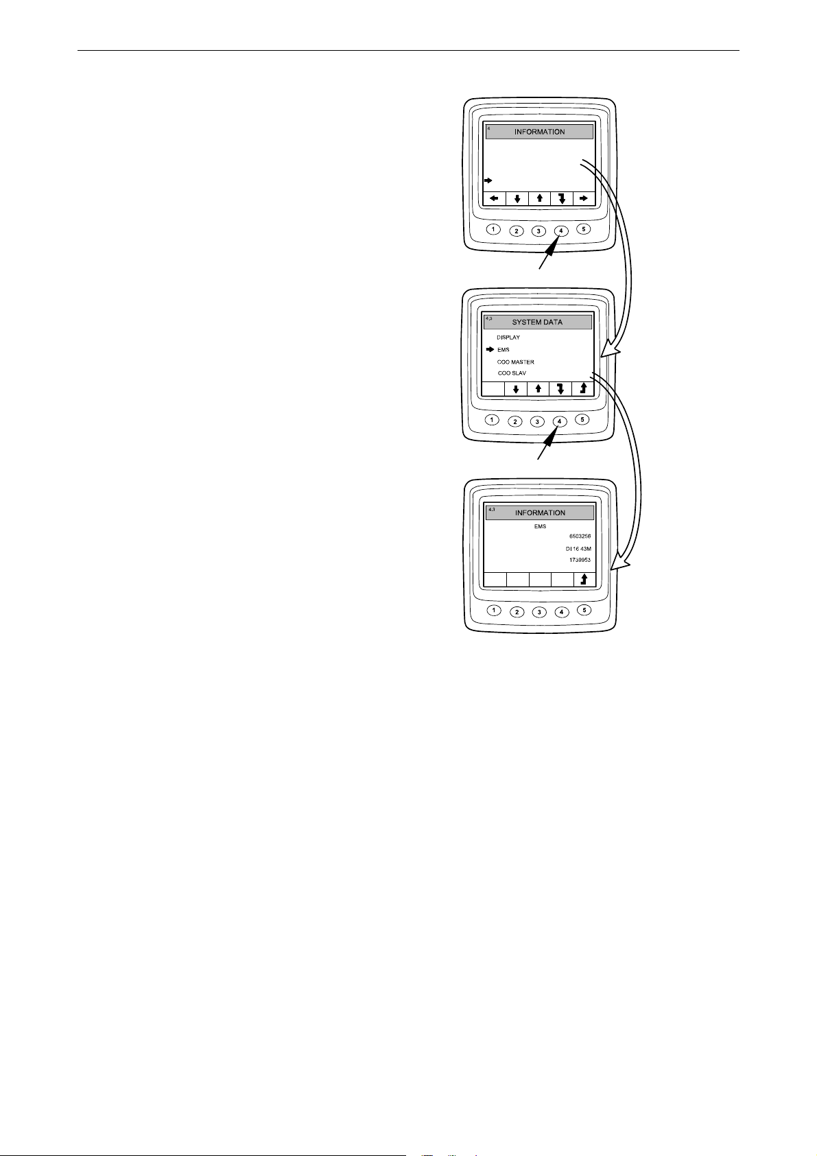
System data (4.3)
STATISTICS TRI
P
PERFORMANCE
SYSTEM D
ENGINE NO
ENGINE
TYPE
PART NO
ATA
341 597
Go down 2 steps in the list by pressing button 2.
Then go down one step in the structure to the
System data display by pressing button 4.
Information about the different system control
units is displayed in this display mode:
• Digital display (Display)
• Engine control unit (EMS)
• Coordinator (COO Master)
• SCR control unit
Move up and down the list by pressing buttons 2
and 3.
Display information about the control unit concerned by pressing button 4.
Digital display (Display)
Information on:
Digital display
• Part number (assembly part number)
• Hardware number
• Software number
• Version number
Engine control unit (EMS)
Information on:
• Engine serial number
• Engine type
• Engine control unit part number
Coordinator
Information on:
• Part number (assembly part number)
• Hardware number
• Software number
• Version number
SCR control unit
Information on:
• Hardware number
• Software number
OPM 500 en-GB 20
©
Scania CV AB 2014, Sweden
Page 21
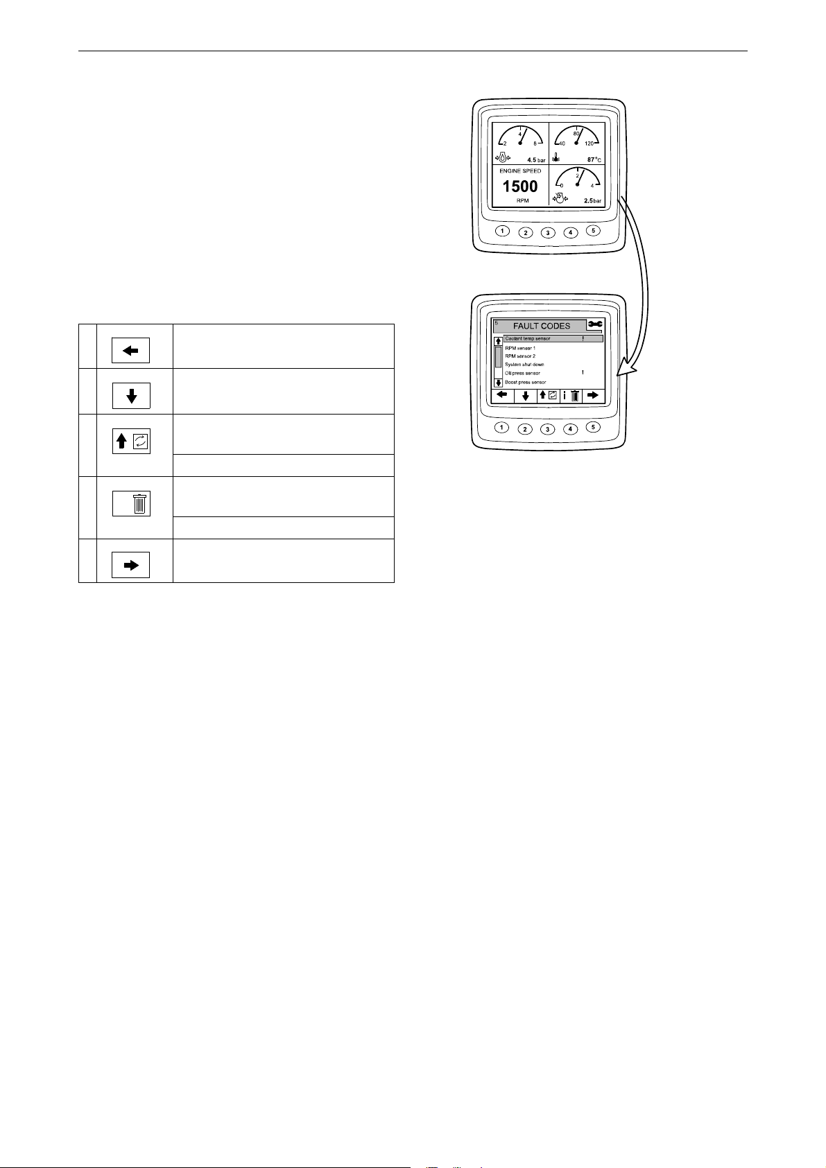
Fault codes (5)
341 598
3
2
1
1
2
7
321 143
321 144
i
321 145
3
2
1
1
4
6
This is how to go to the Fault codes display mode
from a favourite screen:
• Press any button to display the button bar on
the screen.
• Use button 1 or 5 to scroll in a favourite
screen to open the Fault codes display mode.
The button bar changes appearance and remains on the screen.
Digital display
1
Scroll to the left in the top level
2
Go down one step in the list
3 Short press: Go up one step in the
list
Long press (3 s): Update the list
4 Short press: Display information
about the selected fault code
Long press (3 s): Clear fault codes
5
Scroll to the right in the top level
In the example, the Coolant temp sensor and Oil
press sensor are marked with an !, which means
that they are active fault codes.
OPM 500 en-GB 21
©
Scania CV AB 2014, Sweden
Page 22

Information about the high-
341 599
341 600
lighted fault code
In the example on the previous page, Coolant
temp sensor is selected. Give a short press on
button 4 to bring up the information screen for
the fault code.
Digital display
View on dis-
Description In the example
play
EMS Control unit in
which the fault
was registered
Coolant temp
sensor
Name of fault
code
Start problem How the system
reacts when the
fault is active
Code The number of
the selected
fault code
Status Fault status, i.e.
active or passive
Counter How many
times the fault
has occurred
Engine control
unit
Coolant temperature sensor
Starting problems
2001
Active
3 times
Clear fault codes
• Hold control 4 down for 3 seconds.
• Delete all fault codes by pressing button 1.
• Confirm deletion by pressing button 3.
OPM 500 en-GB 22
©
Scania CV AB 2014, Sweden
Page 23

Update the fault code list
341 601
1
2
3
4
5
1
2
3
4
5
6
SETTINGS
BRIGHTNESS/LIGH
T
BUTTON BLEE
P
LANGUAGE
UNITS
ENGINE
BASE SYSTEM
6
SETTINGS
BRIGHTNESS/LIGH
T
BASE SYSTEM
-
+
-
+
341 602
• Hold control 3 down for 3 seconds.
• Confirm the update by pressing button 3.
Digital display
Settings (6)
• Use button 1 or 5 to scroll in a favourite
screen to open the Settings display mode.
• Move up and down the list by pressing buttons 2 and 3.
To get to Settings more quickly, regardless of
where you are in the structure, press buttons 2
and 4 simultaneously.
Contrast/brightness (6.1)
• Select Contrast/brightness and press button 4.
This will take you to the adjustment mode.
• Adjust the brightness and the contrast to current operating conditions.
You can reset the contrast and brightness to the
default settings by holding buttons 2, 3 and 4
down at the same time for 3 seconds.
Go back to the Settings display mode by pressing
button 5.
OPM 500 en-GB 23
©
Scania CV AB 2014, Sweden
Page 24

Button beep (6.2)
Note:
1
2
3
4
5
1
2
3
4
5
6
SETTINGS
6
SETTINGS
BUTTON BLEE
P
OFF
341 603
.2
BRIGHTNESS/LIGH
T
BUTTON BLEE
P
LANGUAGE
UNITS
ENGINE
BASE SYSTEM
1
23
4
5
1
23
4
5
6
SETTINGS
6
.
3
LANGUAGE
ENGLIS
H
SVENSK
A
FRANCAI
S
DEUTSC
H
IT
ALIAN
O
ESP ANO
L
341 604
BRIGHTNESS/LIGH
T
BUTTON BLEE
P
LANGUAGE
UNITS
ENGINE
BASE SYSTEM
• Select Button beep and press button 4. This
will take you to the adjustment mode.
• Switch between button beep off and button
beep on by pressing button 3.
Go back to the Settings display mode by pressing
button 5.
The Button beep off setting does not affect the
alarm signal.
Digital display
Language (6.3)
Information on the display can be shown in 7 different languages:
• English
•Swedish
•German
•French
• Spanish
• Italian
• Portuguese
The default setting is English.
• Select Language and press button 4. This will
take you to the adjustment mode.
• Select the required language with buttons 2
and 3.
• Confirm by pressing button 4. The box on the
right will be selected as an acknowledgement
that the change has been saved.
Go back to the Settings display mode by pressing
button 5.
OPM 500 en-GB 24
©
Scania CV AB 2014, Sweden
Page 25

Units (6.4)
BRIGHTNESS/LIGH
T
BUTTON BLEE
P
LANGUAGE
UNITS
ENGINE
BASE SYSTEM
METRIC
US IMPERIA
L
METRIC
US IMPERIA
L
SETTINGS
UNITS
UNITS
341 605
It is possible to choose between 2 different units
– metric and US Imperial:
Parameter Metric US Imperial
Pressure Bar Psi
Voltage V V
Engine speed rpm rpm
Temperature °C °F
Fuel consumption L/h, L US gallons/h,
US gallons
• Select Units and press button 4. This will take
you to the adjustment mode.
• Select the unit by pressing button 2 or 3.
• Confirm by pressing button 4. The box on the
right will be selected as an acknowledgement
that the change has been saved.
Digital display
Display the information in the above table by
pressing button 1.
Go back to the Settings display mode by pressing
button 5.
OPM 500 en-GB 25
©
Scania CV AB 2014, Sweden
Page 26
Engine (6.5)
WARNING!
1
2
3
4
5
1
2
3
4
5
6
6
1
2
3
4
5
6
ENGINE
.5
P
ASSWORD
0
00
0
SETTINGS
OK
W
ARNING
ENGINE SETTINGS
CAN NOW BE CHANGED
341 606
BRIGHTNESS/LIGH
T
BUTTON BLEE
P
LANGUAGE
UNITS
ENGINE
BASE SYSTEM
SETTINGS
In this display mode, you can change the default
settings of the engine.
If you change the default settings of the engine,
it can affect safety-critical functions.
• Select Engine and press button 4. This will
take you to the adjustment mode.
1
• Enter the password
• A warning is displayed. Press button 3 to proceed to the list of parameters that can be set.
The engine settings that can be changed are described on this page and on subsequent pages.
and press button 4.
Digital display
Idling (6.5.1)
Low idling for PDE engines can be set between
500 and 1,300 rpm.
Low idling for XPI engines can be set between
600 and 750 rpm.
It is not possible to change the idling setting if
the coolant temperature is below 50°C (122°F)
or if the engine is running at raised low idling
speed for some reason.
1. The default password is 2222, but this can be changed by
OPM 500 en-GB 26
the user. See section 6.5.9.
©
Scania CV AB 2014, Sweden
Page 27

Lower temperature limit (6.5.2)
1
2
3
4
5
6
.5
ENGINE
IDLE SPEED
HIGH TEMP LIMI
T
FIXED SPEED
FIXED SPEED
1
2
SAFETY SWITCH
LOW TEMP LIMI
T
341 607
The lower temperature limit, which has a default
setting of 95°C (203°F), is the level for the alarm
and for torque reduction if torque reduction has
been selected. See section 6.5.8.
The lower temperature limit can be set between
85°C (185°F) and 105°C (221°F). The lower
temperature limit cannot be set to a higher value
than the upper temperature limit.
Upper temperature limit (6.5.3)
The upper temperature limit, which has a default
setting of 105°C (221°F), is the level for the
alarm and also for engine shutdown if engine
shutdown has been selected. See section 6.5.8.
The upper temperature limit can be set between
95°C (203°F) and 105°C (221°F). The upper
temperature limit cannot be set to a lower value
than the lower temperature limit.
Digital display
Engine speed setting 1 (6.5.4)
Engine speed setting 1 is a constant idling speed
set and activated from the control panel. See section Engine speed setting 1 and 2.
An upper torque limitation for engine speed
setting 1 can be set in the digital display. The setting only applies when engine speed setting 1 is
activated.
OPM 500 en-GB 27
©
Scania CV AB 2014, Sweden
Page 28

Engine speed setting 2 (6.5.5)
WARNING!
Engine speed setting 2 is a constant idling speed
set and activated from the control panel. See section Engine speed setting 1 and 2.
An upper torque limitation for engine speed
setting 2 can be set in the digital display. The setting only applies when engine speed setting 2 is
activated.
Idling switch (6.5.6)
The idling switch is a safety function in Scania's
electrical system which checks that the accelerator pedal is functioning correctly.
The idling switch is a closing switch that is activated when the accelerator pedal is activated.
The function can be disengaged.
Digital display
If the idling switch is disengaged, a safety function is disengaged.
Fuel density (6.5.7)
The fuel density affects the calculation of the engine power, and it can be changed in the default
settings for the engine. The default setting is
840 kg/m
tween 700 and 1,000 kg/m
3
, but the fuel density can be set be-
3
.
OPM 500 en-GB 28
©
Scania CV AB 2014, Sweden
Page 29
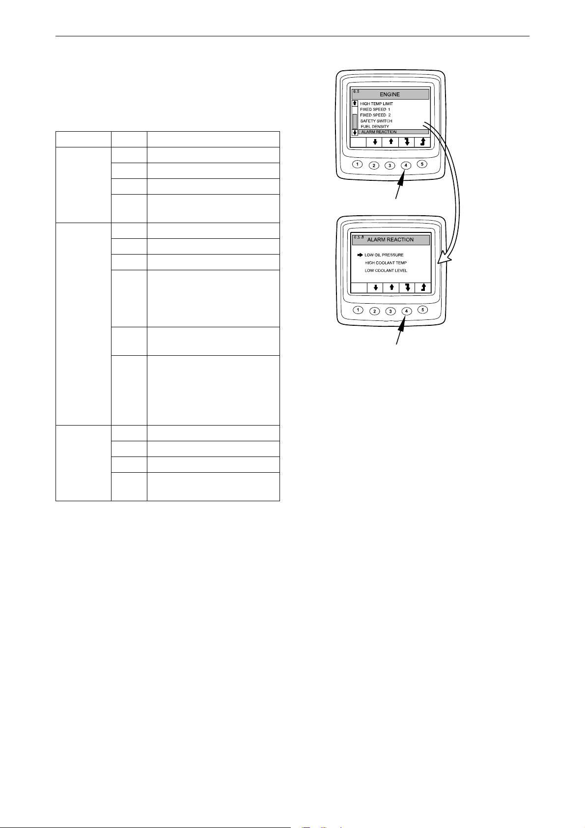
Alarm reaction (6.5.8)
341 608
The engine behaviour may vary depending on
how the engine control unit is programmed.
Signal Line Engine behaviour
1 Alarm only
Low oil
pressure
High coolant temperature
Low coolant level
2 Alarm and torque reduction
3 Alarm and engine shutdown
4 Engine shutdown with over-
ride
1 Alarm only
2 Torque reduction
3 Engine shutdown
Torque reduction at lower
temperature limit
4
Engine shutdown at upper
temperature limit
5 Engine shutdown with over-
ride
Torque reduction at lower
temperature limit
6
Engine shutdown with override at upper temperature limit
1 Alarm only
2 Alarm and torque reduction
3 Alarm and engine shutdown
4 Engine shutdown with over-
ride
Digital display
• Select Alarm reaction and press button 4.
This will take you to the adjustment mode.
• Select signal type by pressing button 2 or 3.
• Press button 4 to go to the next level.
OPM 500 en-GB 29
©
Scania CV AB 2014, Sweden
Page 30
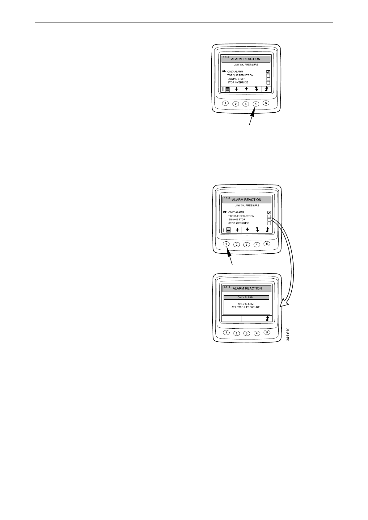
• Select an alarm reaction with buttons 2 and 3.
341 60
9
• Confirm by pressing button 4. The box on the
right will be selected as an acknowledgement
that the change has been saved.
Display a more detailed description of the selected alarm reaction by pressing button 1.
Digital display
Go back to the Settings display mode by pressing
button 5.
OPM 500 en-GB 30
©
Scania CV AB 2014, Sweden
Page 31
Change password (6.5.9)
Note:
1
2
3
4
5
6
.5
ENGINE
FIXED SPEED
FIXED SPEED
1
2
SAFETY SWITCH
FUEL DENSIT
Y
ALARM REACTION
1
23
4
5
6
.5
ENGINE
CHANGE PASSWORD
CHANGE PASSWORD
1
2
3
4
1
2
3
4
5
6
.5
ENGINE
123
4
CONFIRM
1
23
4
5
6
.5
ENGINE
P
ASSWORD
CHANGED
341 6
1
1
OK
You can set a new password. Valid values are
0001–9999.
• Select Change password and press button 4.
This will take you to the adjustment mode.
• Enter the password and press button 4.
• Confirm the password by pressing button 4.
• Go back by pressing button 3.
Contact your nearest Scania distributor if you
have forgotten the password.
Digital display
OPM 500 en-GB 31
©
Scania CV AB 2014, Sweden
Page 32
Examples of setting
Note:
1
2
3
4
5
1
2
3
4
5
6
SETTINGS
BRIGHTNESS/LIGH
T
BUTTON BLEE
P
LANGUAGE
UNITS
ENGINE
BASE SYSTEM
6
1
2
3
4
5
6
ENGINE
.5
P
ASSWORD
0
00
0
SETTINGS
OK
W
ARNING
ENGINE SETTINGS
CAN NOW BE CHANGED
1
23
4
5
6
.5
ENGINE
IDLE SPEED
HIGH TEMP LIMI
T
FIXED SPEED
FIXED SPEED
1
2
SAFETY SWITCH
LOW TEMP LIMI
T
1
23
4
5
6
ENGINE
.5
.5
-
+
LOW TEMP LIMI
T
(85 C)
95
(105 C)
o
o
341 612
Set lower temperature limit (6.5.2)
• Select Engine and press button 4. This will
take you to the adjustment mode.
• Enter the password and press button 4.
• A warning is displayed. Press button 3 to proceed to the list of parameters that can be set.
• Move up and down the list by pressing buttons 2 and 3.
• Press button 4 when Lower temp limit has
been selected.
• Press button 4 again. This will take you to the
adjustment mode.
• increase or reduce the value by pressing button 2 or 4.
Digital display
When one of the buttons is pressed, the old value
is automatically deleted and the new value saved.
• Go back to the Settings by pressing button 5.
You can set other parameters in the same way.
OPM 500 en-GB 32
©
Scania CV AB 2014, Sweden
Page 33

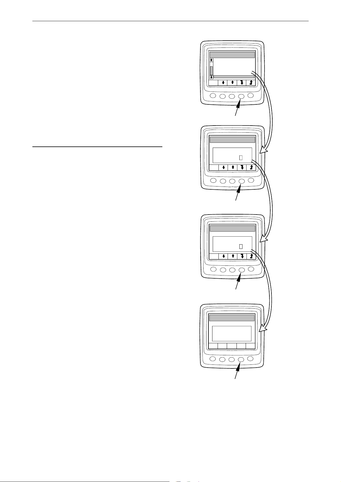
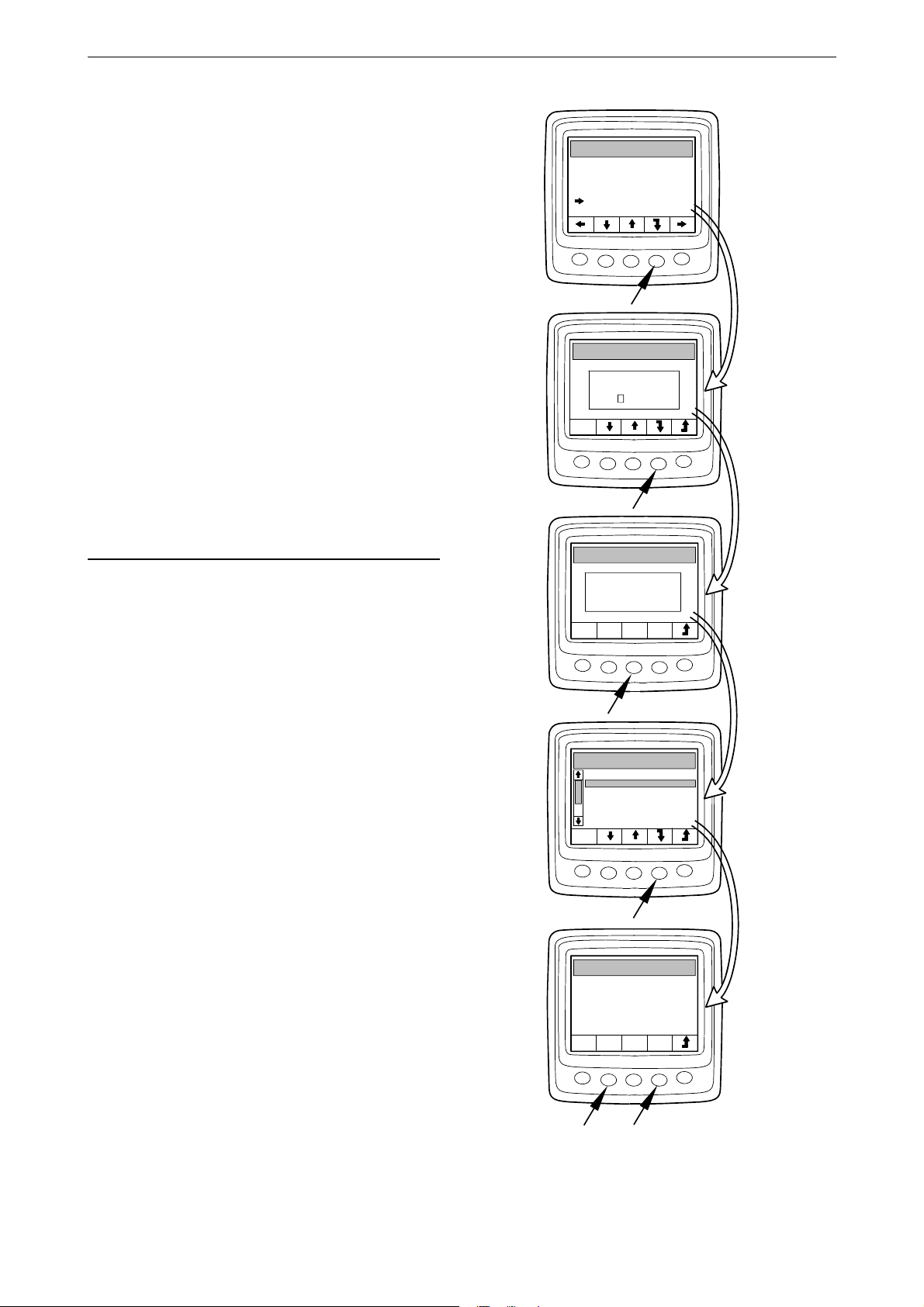
Base system (6.6)
1
2
3
4
5
6
SETTINGS
BRIGHTNESS/LIGH
T
BUTTON BLEE
P
LANGUAGE
UNITS
ENGINE
BASE SYSTEM
1
23
4
5
6
.6
BASE SYSTEM
NO
SINGLE
DOUBLE
341 613
321 162
321 163
321 164
-
+
321 165
You can configure the digital display for the
electrical system it will be used with in Base system mode. The options are:
•None
•Single
• Double
• Select Base system and press button 4. This
will take you to the adjustment mode.
• Select the type of base system by pressing
button 2 or 3.
• Confirm by pressing button 4. The box on the
right will be selected as an acknowledgement
that the change has been saved.
• Go back to the Settings by pressing button 5.
Alarm and fault code generation
Alarm and fault code generation
Both new alarms and fault codes generate dialogue boxes in the digital display. The dialogue
box for alarm has the highest priority of all functions in the digital display.
Alarms
There are 7 different alarms in the system.
Alarm Icon Comments
Low oil pressure
High coolant temperature
Low coolant level
Alternator not charging System voltage displayed
SCR fault
Low reductant level
Oil level too high or low
OPM 500 en-GB 33
©
Scania CV AB 2014, Sweden
Page 34
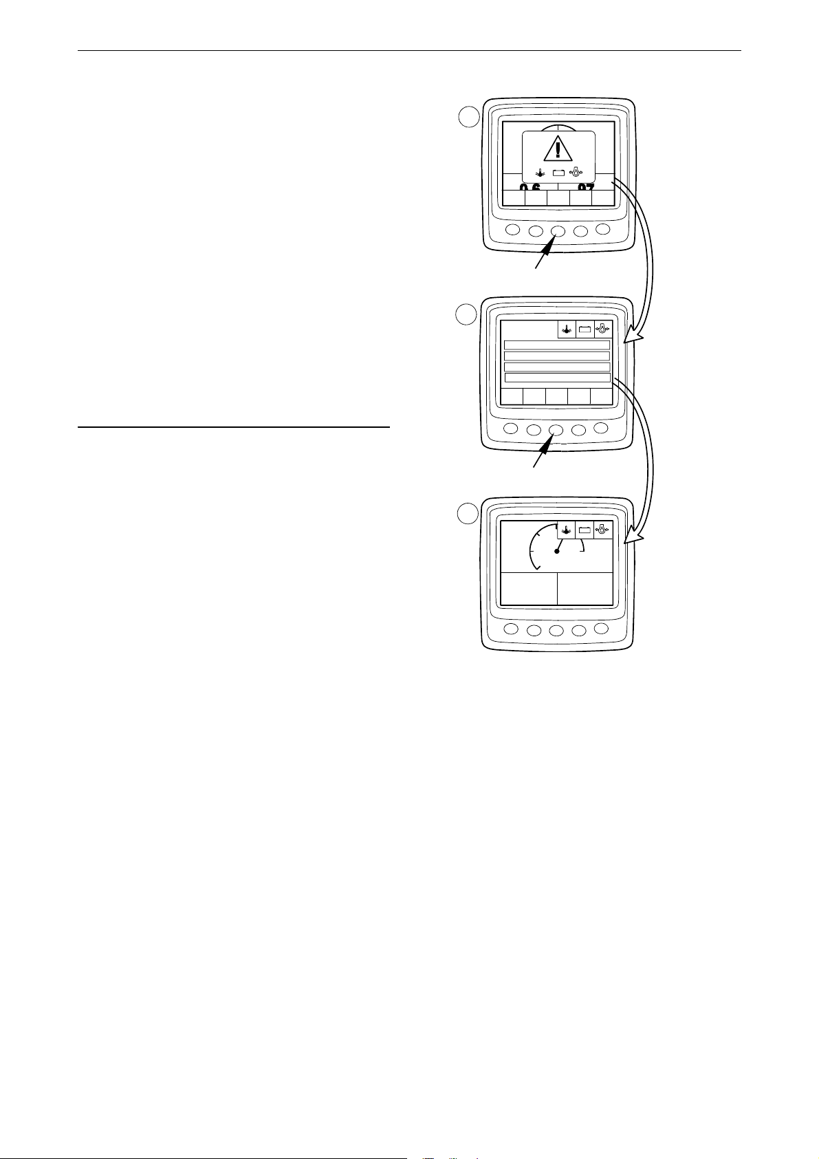
Alarm function
Note:
1
23
4
5
1
2
3
4
5
-
+
OK
-
+
-
+
A
B
C
o
C
bar
RPM
1
23
4
5
1800
5
25
x100
OIL PRESSURE
COOLAN
T
TEM
P
0.6
97
1
ENGINE SPEED
1500 R/MIN
OIL PRESSURE
0.6 BAR
COOLAN
T
TEM
P
97 C
VOLTAGE
16V
o
OK
341 614
When an alarm is generated, a warning is shown
in the display together with the alarm icon. At the
same time, an alarm signal sounds both in the analogue instrument panel and the digital display.
Acknowledge the alarm signal in the digital display by pressing button 3. If several alarms are
active, acknowledge one alarm at a time. See
figure A.
Each acknowledged alarm is then displayed as
an icon at the top right of the display as long as
the fault is active. The alarm is displayed regardless of which screen is active.
All alarms must be acknowledged before the
next screen will be displayed.
Alarm and fault code generation
The screen in figure B always has the same content.
If you press button 3 in figure B, you will return
to the screen displayed before the first alarm was
generated. See figure C.
©
Scania CV AB 2014, Sweden
OPM 500 en-GB 34
Page 35

External alarm signal
Output for external alarm
OIL PRESSURE
COOLANT
TEM
P
341 615
When an alarm is generated, pin 11 in the 12-pin
display connector is activated. The output can be
used to activate a warning lamp or suchlike. In
this case use pin 11 to ground a warning lamp.
Maximum current 200 mA. Use a relay if a higher current than 200 mA is required. See illustration.
Alarm and fault code generation
Fault code generation
There are several fault codes in the electrical system to help when a system fault or engine fault
occurs.
When a new active fault code is registered in the
system, it will be shown on the display as in figure A.
Acknowledge all active fault codes by pressing
button 3. The next screen then displays a fault
code icon at the top right as shown in figure B.
The icon is always displayed when at least one
fault code is active.
When starting the system, a dialogue box as in
figure A is always displayed if there is at least
one active fault code.
OPM 500 en-GB 35
©
Scania CV AB 2014, Sweden
 Loading...