

Page 1

To User
To User
Scania Higer A30, mounted with original SCANIA chassis, is a
newly developed deluxe c oac h.
The coach mainly runs on the high graded road and highway for
passenger transportation and tourism, et c.
This driver’s instruction cont ains oper ation, st ructure, specification
and maintenance of the c oach b ody. You are kindly advised to rea d the
manual carefully for the correct operation and maintenance of your
coach.
In regard to the chassis instruction, please read the “Scania
Driver’s Instructions” and keep the operating instructions within the
vehicle.
Correct operation and maintenance can result in good
performance and longer service of the coach and lower operating
costs.
This driver’s instruction is edited on basis of the products before
delivery from the factory. Higer Bus Company Limited reserves the
right to modify the specification or change the parts or components of
this model at any time without m odification of the delivered coaches.
In case of any questions or suggestions concerning our coaches,
you are welcome to provide feedback for our continuous improvement
of our products as well as better service to you.
Higer Bus Company Li mit ed
June 2012
Page 2

Catalog
Catalog
Vehicle Identification ............................................................. 1
Specification .......................................................................... 2
Body structure ....................................................................... 4
Driver’s area ......................................................................... 5
Passenger door ..................................................................... 6
Safety equipment ................................................................ 12
Rocker switch ...................................................................... 19
Driver’s seat ........................................................................ 29
Rear view mirror .................................................................. 32
Passenger area ................................................................... 34
Electronic clock ................................................................... 36
Microphone amplifier ........................................................... 39
DVD .................................................................................... 40
LCD ..................................................................................... 69
Reverse monitor .................................................................. 70
Air conditioning ................................................................... 72
Heating system ................................................................... 81
Defroster ............................................................................. 84
Electrical part ...................................................................... 87
Page 3
Vehicle Identification
Nameplate
Vehicle Identification
The coach body nameplate is riveted on the RHS door entrance
panel of the front passenger door entrance.
1
Page 4

Specification
Body
Parking on slope % ≥ 20
Passenger door - Out swing
Roof hatch 2
Window -
Electrical apparatus - 24V negative grounded
Specification
Double glazing front
windshield, the rest is
tempered glass
A/C system
Inner
equipment
Type -
Cooling power kw 30
Refrigerant - R134A
Media player
Roof mounted condenser
and evaporator
2
Page 5

Specification
Daylight lamp+ LED night
equipment
Inner
xenon headlamps/
Front headlamps -
halogen headlamps
lamp
Floor leatheroid
Composite floor
Guardrail - -
CAN -
-
domestic floor leatheroid
-
-
3
Page 6
Body structure
5
Windscreen
10
Rear wheel
Body structure
1 Front fog lamp 6 Rear view mirror
2 Headlamp 7 Passenger door
3 Decoration panel 8 Front wheel
4 Windscreen wiper 9 Luggage compartm ent
4
Page 7
Driver’s area
2
Microphone amplifier
13
Gear selection button
3
Media player
14
Brake pedal
4
Reverse monitor
15
Accelerator pedal
5
Vent
16
Rocker switch(L-panel)
Rear view mirror
7
Combination switch
18
Microphone
8
Steer ing wheel
19
A/C control panel
9
Ignition switch
20
Parking brake
10
Instrument cluster
21
Driver’s seat
Driver’s area
1 Rocker switch(Centre console) 12 Retarder control handle
6
Rocker switch
11 Rocker switch and Headlamp
knob
17
control button
5
Page 8
Passenger door
Passenger door
1. Mechanical lock
The mechanical lock is installed on the outside of front door panel.
Unlock the door
Rotate the lock cover by 180° to expose the key hole;
Insert the key and turn clockwise by 90°;
Turn the handle (with the key) clockwise by 90° and then
release it. The handle will automatically turns back by 90° and
the lock pin extends out;
Turn the key counterclockwise by 90° and then withdraw the
key;
Rotate the lock cover to cover the key slot.
Lock the door
Rotate the lock cover by 180° to expose the key hole;
Insert the key and turn clockwise by 90°;
Turn the handle (with the key) counterclockwise by 90° and then
release it. The handle will automatically turns back by 90° and
the lock pin extends out;
6
Page 9
Passenger door
Turn the key counterclockwise by 90° and then withdraw the
key;
Rotate the lock cover to cover the key hole.
Caution:
Once the door is secured by the key, the electro-pneumatic
controls of the door are disabled.
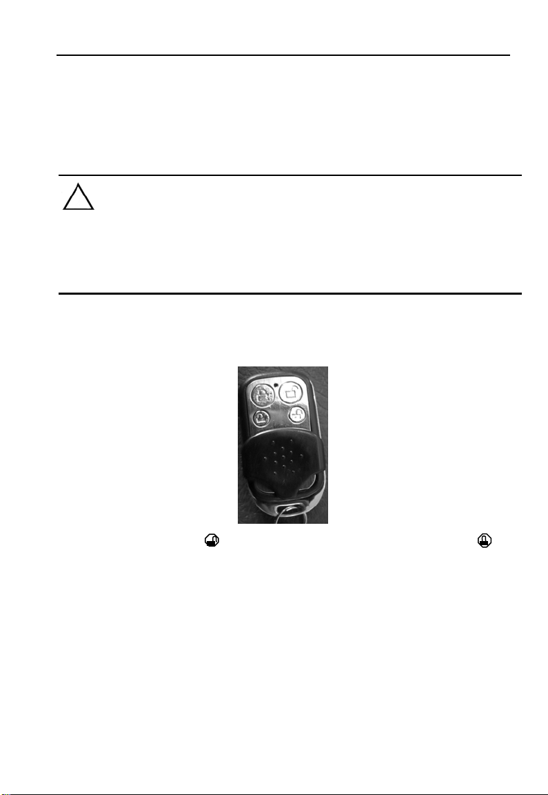
2. Remote control
Press the button“ ” to unlock the door. Press the button” ” to
lock the door.
Replace the battery in the remote control when the indicator
light becomes dim or the control distance is reduced
drastically;
The upper buttons control the fr ont passenger door, the lower
switch control the middle passenger door;
Each remote control is coded to ensure its uniqueness. Each
new coach is delivered equipped with two remote controls. If
7
Page 10
Passenger door
they are lost, contact your Scania dealer.
If the coach is equipped with only the front passenger door , the
remote control will only contains the upper row buttons.
Note:
1) The remote control will only function when the handbrake is
applied or the air pressure in the system is within the normal
range.
2) The spare remote control should be kept in a safe location;
3) Do not throw or mishandle the remote controller
3. Rocker switch on dashboard
The battery master switch if turned on (by pressing the lower
edge) will connect to bulk of the electrical system to the battery.
The driver can control the door with the rocker switch on the
instrument cluster. “1” switch control the passenger door.
Press the upper or lower part of a rocker sw itch to open or shut
8
Page 11
Passenger door
the door.
Warning:
1) Ensure that there is no obstacle before operating the
passenger door.
2) If the passenger door is obstructed by any person or objects
during closing, it will re-open automatically.
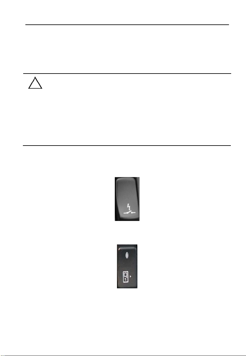
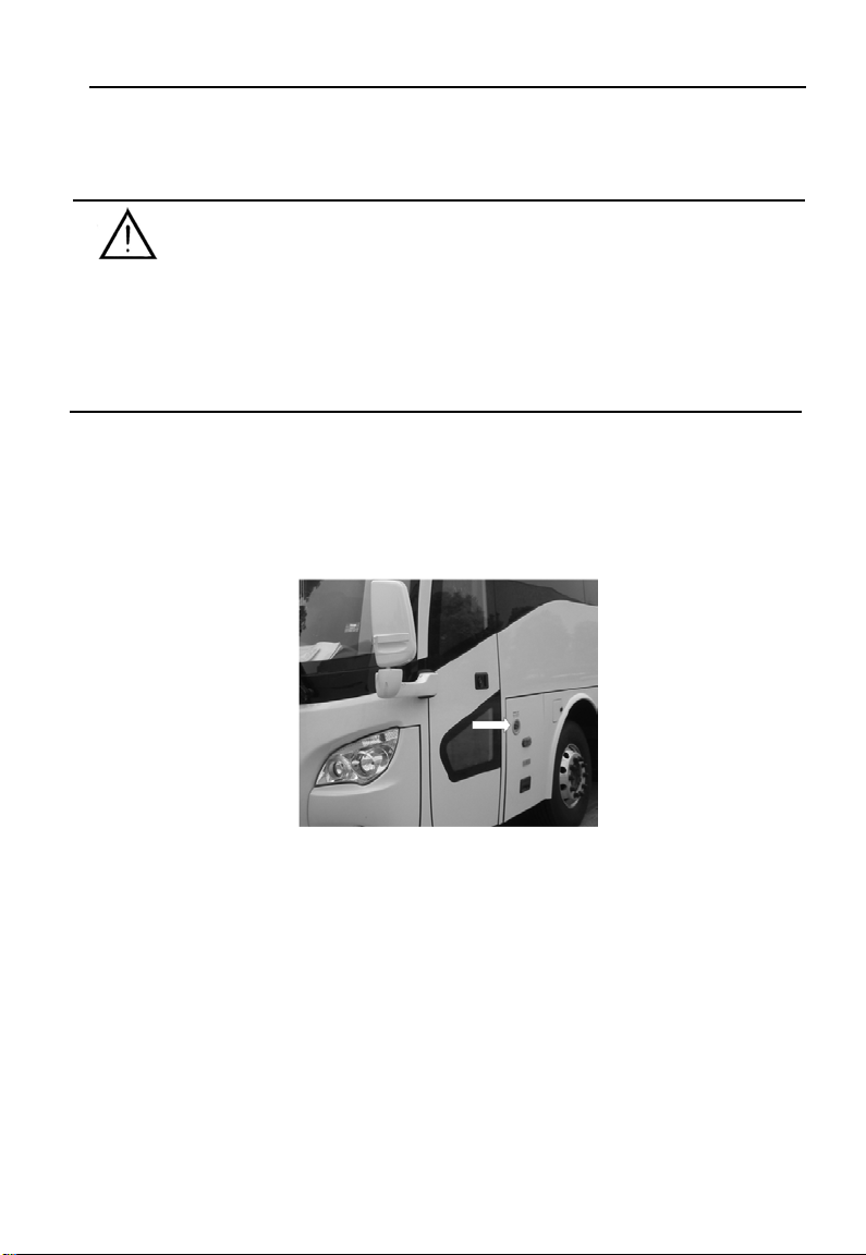
4. Emergency switch
Outer emergency switch
Position of the outside emergency switch of front door: The switch is
installed close to the front door;
Position of the outside emergency switch of middle door: The switch is
installed close to the middle door.
Operation:
In an emergency, rotate the red emergency knob clockwise to
release the air pressure in the pump. The door can then be
opened manually by pushing/pulling.
Reset the red emergency knob to its initial position before
9
Page 12
Passenger door
reverting to the normal door control.
If the vehicle is not in use for extended period, turn on the
emergency switch. This will release the air pressure in the
pneumatic pipelines.
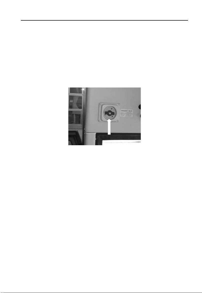
Inner emergency switch
Position of the inner emergency swit ch: The valve is installed above
the front or middle door in the coach.
Operation:
In an emergency, rotate the red emergency knob clockwise and
push open the door by hands.
Rotate the red emergency knob counterclockwise to its initial
position before reverting to normal control.
10
Page 13

Passenger door
Note:
The rocker switch controlling the door on the dashboard and the
remote control will be disabled when the emergency switch is been
turned on.
11
Page 14
Safety equipment
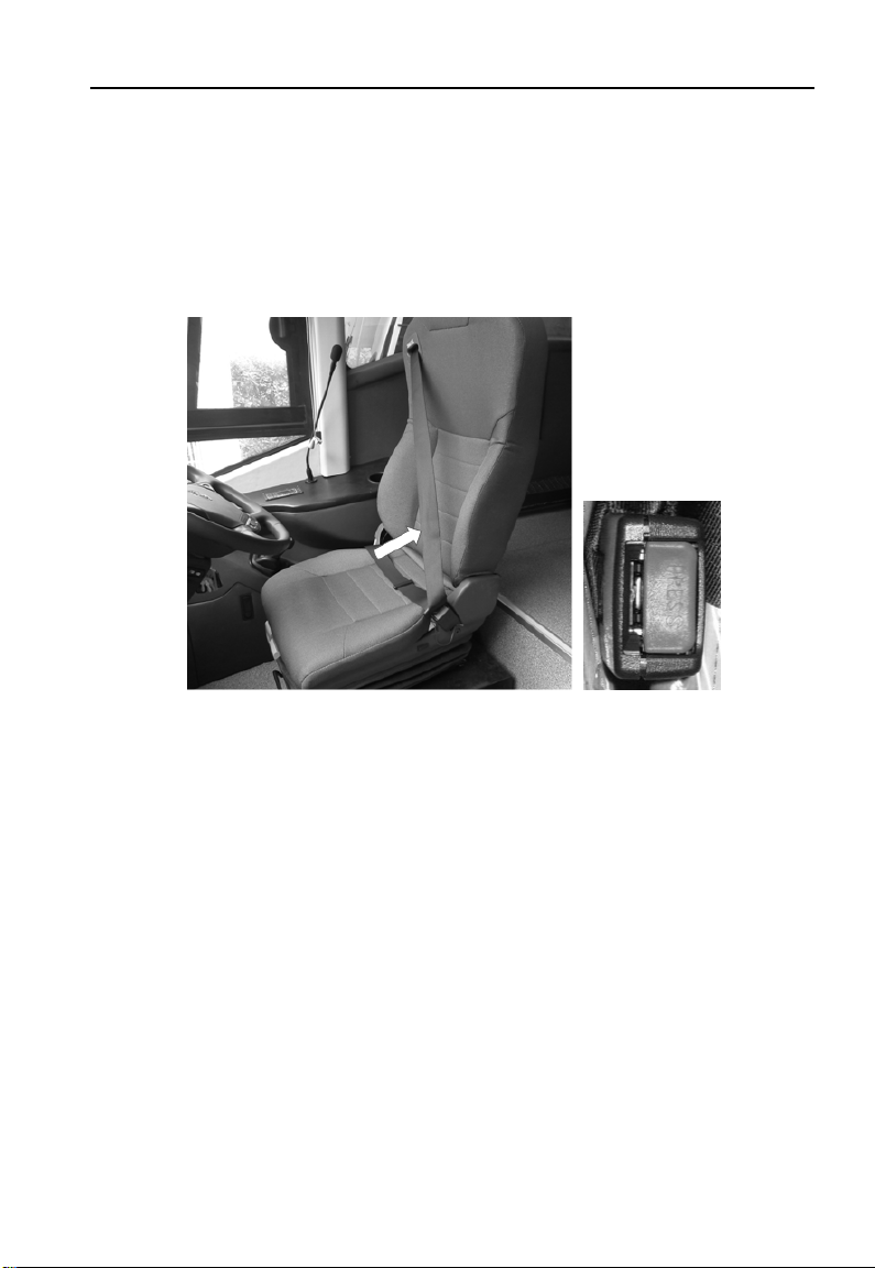
1. Safety belt
Three point safety belt
Safety equipment
Function of safety bel t
Protect the driver and passengers in an emergency.
Operation:
1) Insert the tongue of the belt into the buckle at the cushion as
indicated in the above pictur e. A click sound will ensure that the tongue
is safely “locked” in the buckle.
2) To release, press the RED button at the s id e of the buckle a s sh own
in the above picture. This will unfasten the belt.
3) The three point belt should extend to the chest and hip instead of
12
Page 15

being under the arm or at the waist .
Safety equipment
Note:
1) The seat belt should not be t wisted.
2) Damaged seat belt should not be repaired but r epla ced.
3) Over inclination will prevent the seat belt from normal extension
or retraction.
2. Emergency switch of passenger door
In an emergency, turn the red emergency switch clockwise to
release the air pressure from the pump. The door can then be
pushed open by hand. Rotate the switch counterclockwise to its
initial position before reverting to the normal door control. (Refer to
the related passenger door for details)
Warning:
Do not operate the emergency switch other than during an
emergency, to avoid any injury.
13
Page 16
Safety equipment
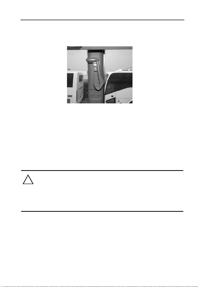
3. Emergency exit window
In an emergency, break the side window to escape.
As the centre part of the tempered glass window is tougher than the
edges, knock the edg e, es peci ally from the t op middl e, by directing the
hammer hitting tip at an angle. Continue hitting until crac ks appear and
the glass is broken. The heels of female shoes can also be used for
the purpose, if there is a lack of hammers. The thinner the heel, the
more effective it wi ll be in breaking the glass.
Note:
Check to ensure all the hammers are at the right positions before
driving each day.
14
Page 17
Safety equipment
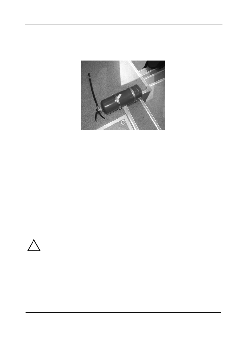
4. Portable fir e ext inguisher
Position:
There is one fi re extinguisher in the bus, which is fixed on the edge of
step stripe beside the driv er.
Operation:
1) Pull out the safety pin completely from the handl e
2) Press the handle, directing nozzle towards the fire, to extinguish
the fire.
Note:
1) Ensure that the fire extinguisher is with a valid cert i ficate.
2) Keep the nozzle away from the skin to avoid any injury;
3) Ensure that the fire extinguishers are secured at right positions
before operating the coach each day.
15
Page 18
Safety equipment
5. Ceiling hatch
Without venti l a t or
Operation:
1. Push the black handle upwards to open one side of the roof
hatch for ventilation.
2. Pull the black handle downwards to close it.
3. In an emergency, pull the emergency handle away from the
hatch horizontally along the ceiling, until the elastic lock pins
release the roof hatch. Push open the hatch upwards for
passengers to escape.
16
Page 19
With ventilator
Safety equipment
②
①Protruding handle ②Red handle
Operation:
①
1. Push the protruding handle upwards to open one side of the roof
hatch for ventilation.
2. Pull the protruding handle downwards to close it.
3. In an emergency, pull the red emergency handle downwards on
both sides and lift the hatch until it can be opened completely for
passengers to escape.
Warning:
Do not open the roof hatch completely unless during an
emergency.
17
Page 20
Safety equipment
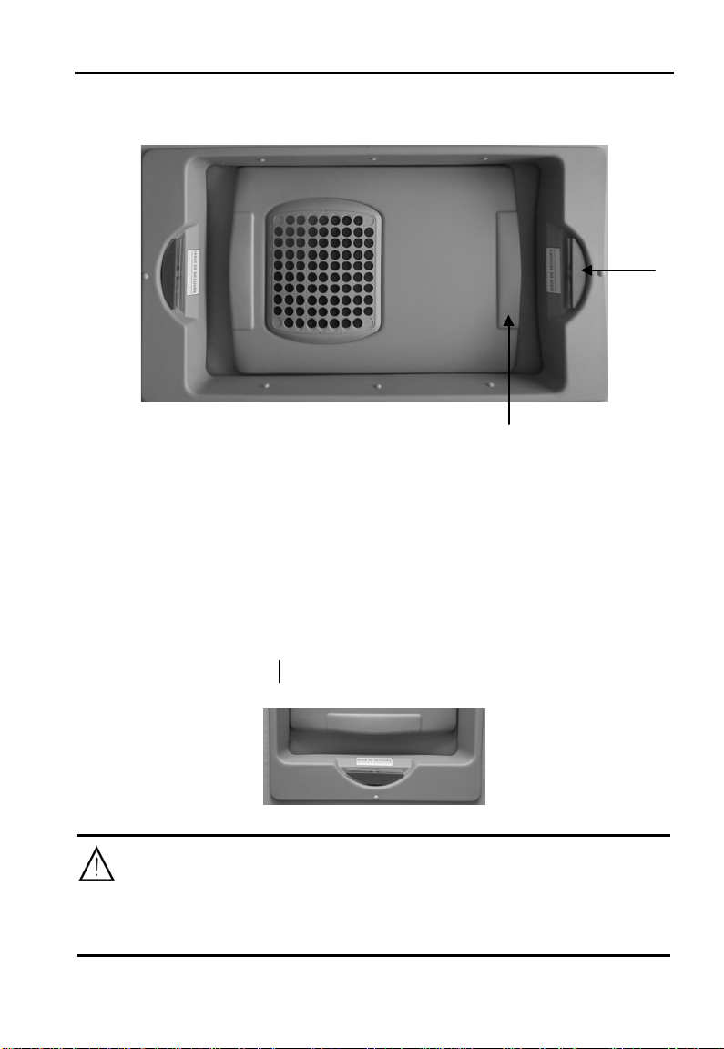
6. Using the correct amperage fuse
When re pla cing f us es, it i s important not to use over-rated fuses as it
may cause overheating and f ire.
18
Page 21
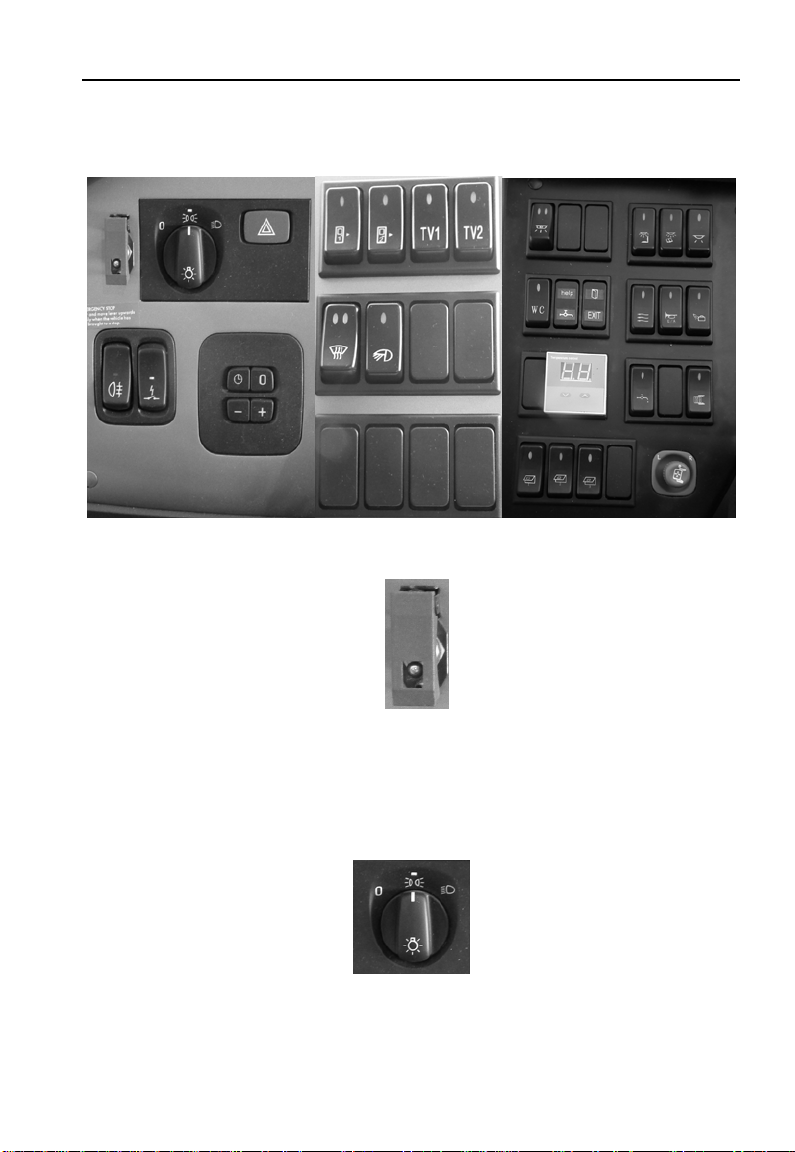
Rocker switch
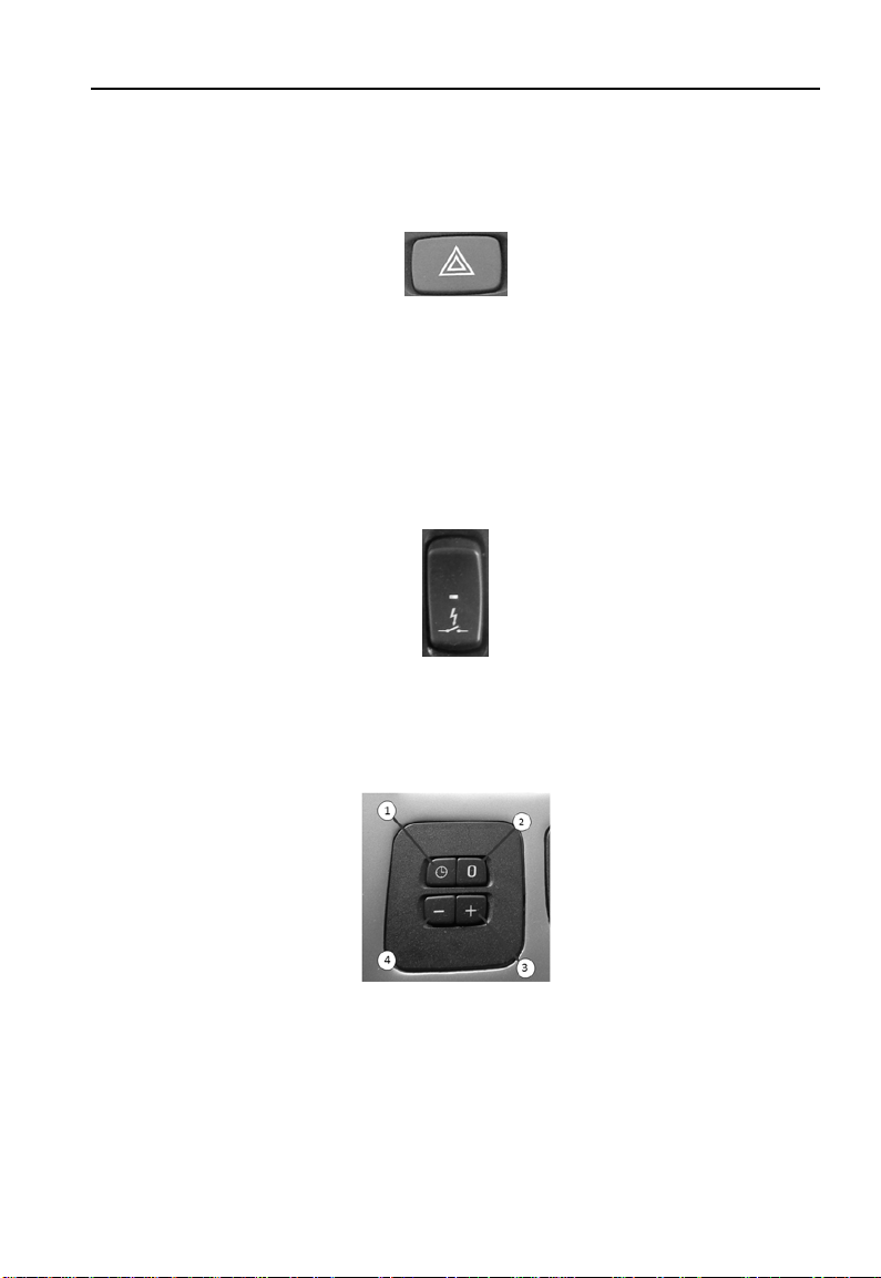
Emergency stop switch
Rocker switch
Remove cover and move lever upwards. Actuate only when the
vehicle has been brought to a stop.
Headlamp knob
Knob with three positions: “0” position, marker lamps, and headlamps.
The marker lam ps a nd t he head la mp s w ill be powered off if the knob is
19
Page 22
Rocker switch
switched to “0” position.
Hazard warning signal
When this switch is depressed, all the turn signal lights on both sides
of the vehicle will flash simultaneously. It is to be used only during
emergency with the vehicle in stationary position, in order to attract
other drivers’ at t ention.
Battery master switch
The battery master switch if turned on (by pres sing the lower edge) w ill
connect to bulk of the elect r ical sy stem to the battery.
Instrument cluster controls but ton
1. Setting for information sign display: time setting.
2. Setting for informatio n sign display: reset.
3. Setting for information sign display: decrease value.
4. Setting for information sign display: increase value.
20
Page 23
Rocker switch
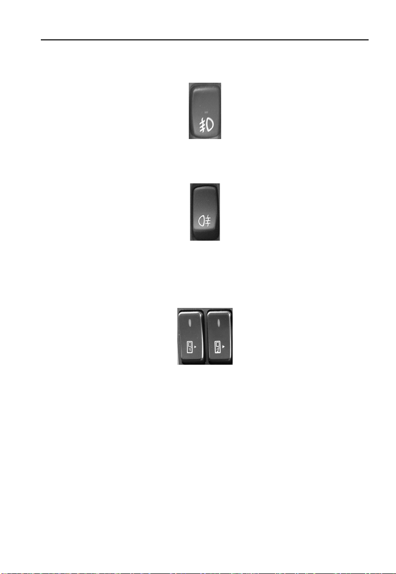
Front fog lamp switch
This switch controls the fr ont fog lamp.
Rear fog lamp switch
Only with the front fog switch turned on, will this switch functions,
switching on the rear fog lamp.
Passenger door switches
These two switches control the front and middle passenger doors;
press the upper or lower side of the switch will open or close the
relevant passenger door respectively. The number on the two switches:
“1” controls the front door, and “2” controls the middle door.
21
Page 24
Rocker switch
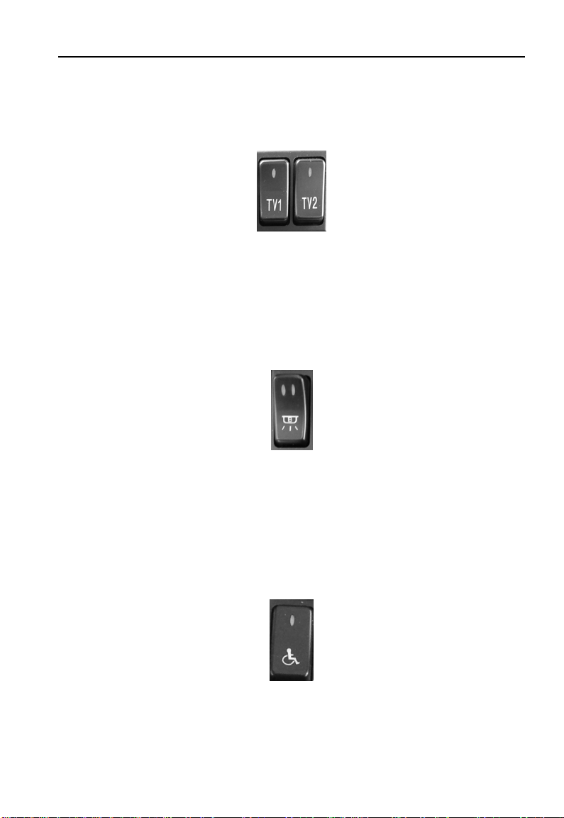
LCD switch
This two switches control the power supply of the front and middle
LCD. Press the side with mark of the rocker switch to turn on the
relevant LCD, TV1 cont r ols front LCD, TV2 controls middle LCD.
Ceiling light switch
This is a switch with 2 levels for different of light intensity required for
the ceiling lights. Press the lower edge (with symbol) of the switch
lightly will light up 50% of the ceiling lights and pressing further to the
nd
2
level will illum inat e all t he cei ling light s.
Warni ng light switch on di s abled pas sengers getting on
Before disabled passengers getting on the bus, press the side with
mark of the rocker switch to turn on the warning lights.
22
Page 25

Rocker switch
Driver’s light switch
This switch controls the light illuminating the instrum ent clust er.
Reading light switch
This is the master switch controlling all the individual passenger
reading lights. The button near to each light, allows for individual
controls of the reading l ig ht for each passenger.
Night illumination light switch
Press the side with mark of the rocker switch to turn on the night
illumination light; press t he other side of the switch to turn off the light.
23
Page 26
Rocker switch
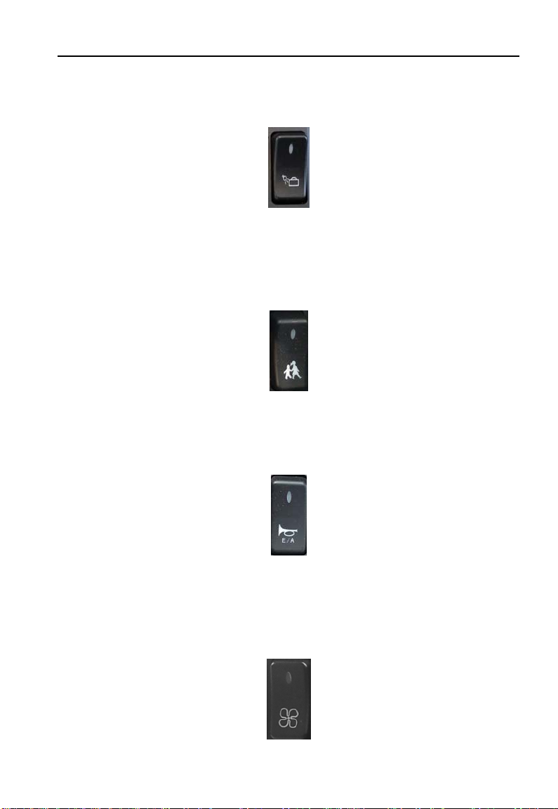
Luggage compartment lamp switch
Press the side with mark of the rocker switch to turn on the luggage
light; press the other side of the switch to turn off the lig ht .
School bus war ni ng light switch
Press the side with mark of the rocker switch to turn on school bus
warning light; press the ot her side of the switch to turn off the l ig ht.
Horn shift switch
The horn reset switch a llo w s the driv er t o either opt for the us e o f air or
electric horn.
Ventilator switch
24
Page 27

Rocker switch
The ventilator switch controls two ventilators in the coach. Press the
marked side of the switch the front ventilator intakes air and the rear
ventilator exhausts air. Press the other side of the switch and the front
one exhausts air and the rear one int akes a ir. When the switch is in the
middle position, the two ventil at or s stop working.
Aisle light switch
Turning on this switch will light up t he aisle lamps.
Water pump switch
Press the side with mark of the rocker switch to start the heating
system water pump.
Rear view mirror defrost switch
Defrosting of the rear view mirrors is through this swi tch.
25
Page 28
Rocker switch
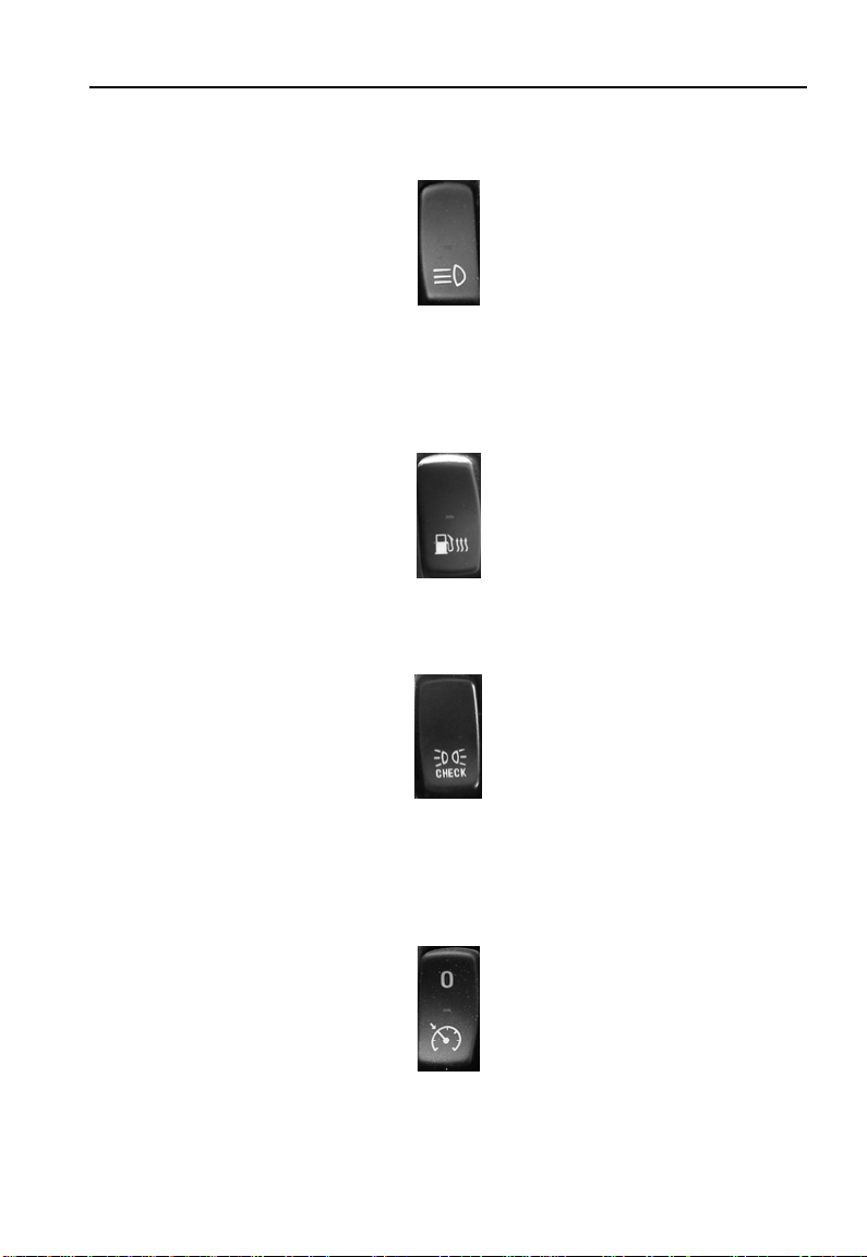
High beam switch
Activates the auxiliary lamps together with the main beam of the
vehicle .
Fuel heating switch
This switch controls the fu el heating system.
T est the external lightin g switch
This bulb check switch enables the driver to test all the external lightings’ proper f unctioning.
Cruise control switch
This switch controls the v ehicle cruise at predetermined speed.
26
Page 29

Rocker switch
White smoke limiter switch
Press the side with mark of the rocker switch to start the white smoke
limiter.
Traction control switch
This switch allows the wh eels t o rotate at different speed
ECAS kneeling switch
This switch controls the vehicle kneeling and restore vehicle to normal
height.
ECAS total raising / total lowering switch
This switch controls the vehicle raising and lowering.
27
Page 30

Rocker switch
ECAS predetermined height / normal height switch
This switch controls the vehicle to predetermined height and restore
vehicle to normal height.
28
Page 31

Driver’s seat
Operation:
(1)Horizont al adjustment
Driver’s seat
Pull lever and move seat forw ar d/ backward.
Release the lever to lock the seat.
(2)Slope adjustment
Pull lever and adjust the slope by loading/unloading the front seat
cushion area.
(3)Seat cushion adj ustment
29
Page 32

Driver’s seat
Pull lever and move the seat cushion forward/backward.
(4)Horizontal su spension
Lever to the right: Horizon tal adjustment released.
Lever to the left: Horiz ontal adjustment locked.
(5)Lowering
Press switch down: seat l ow er s .
Press switch up: seat moves to the adjusted height set.
(6)Damper adjustment
By adjusting the damper, the suspension characteristics of the seat
can be optimally adapted to every roadway and ev ery dr iv er.
Lever up: minimum damp er force.
Lever down: maximum da mp er force.
(7)Height adjustment
Pull or push lever and adjust the seat in desired height.
(8)Integrated pneumatic system (IPS)
Press button to vent and bleed the corresponding air chamber. This
enables an optimal adoption of the backrest to y our body’s shape.
(9)Heating (option)
Thermostatic regulated heating for seat cushion and backrest. To be
switched on or off by sw it ch.
(10)Backrest adjustment
30
Page 33

Driver’s seat
Pull lever and adjust the backrest position by applying your weight to
the backrest.
(11)Shoulder adjustm ent
Pull lever and adjust the upper backrest area in the desired position.
(12)Armrest
The inclination can be adj ust ed by the knurled knob at the front.
Note:
1. Please read the operating instructions thoroughly before using your
ISRI -seat and acquaint yourself with it s technic al features.
2. Keep the operating inst r uct ions within the vehicle.
3. The ISRI -seat has to be installed or repaired by specialists under
consideration of the spec ific country’s regulations.
4. We point out that this s eat is a safety component. Any modifications
to the seat and disregard of the instruction manual may result in an
accident.
5. Due to reasons of road safety, the driver seat must only be adjust ed
when the vehicle is stationary.
6. Seat anchorages and locking par ts have to be checked from time to
time. Replacing the Safety belt to other brand or type other than the
original is not allowed.
31
Page 34

Rear view mirror
Rear view mir ror
1. Outside rear view mirror structure
The lower mirror can be turned around and both lower and upper
mirrors can be defrosted electrically.
2. Outside rear view mirror adjustment switch
The ignition switch should be turned to “ON” before this knob can
function. The left rear view mirror can be adjusted when the white
mark points to “L” and the right one can be adjusted when the white
mark points to “R”. The mirrors are adjustable in four directions (up,
down, left and right).
32
Page 35

Rear view mirror
3. Rear view mirror defroster switch
The rear view mirror defrosting switch is powered only when the
ignition switch is at the “ON” position. Press the lower edge (with
symbol) of the switch, to defrost the rear view mirror and to switch off,
press the upper edge.
Caution:
Switch off the defroster as soon as the mirror is already defrosted in
order to avoid damaging to the defr ost ing element.
33
Page 36

Passenger area
Passenger’s area con t ro l
Passenger area
① ⑧air flow regulator ② ⑦reading lights
③ ⑥reading lights switches ④get off ⑤ loudspeaker
Reading light control
When the reading lights master switch is turned on, the
passengers can press the button ③ and ⑥ to operate the relevant
reading lights.
Air flow regulator
The passengers can adjust the air flow direction and quantity of
air conditioning by rot at in g the regulator ① and ⑧.
34
Page 37

Passenger area
Get off
When the ④ “STOP” button is activated, an alarm and flashing of
indicator on the instrument cluster will be initiated to let driver be
aware.
Radiator vent
The radiator vent is locat ed under the passenger seats.
35
Page 38

Electronic clock
Electronic clock
Production description
This type of the clock can display t ime, temperature and humidity.
1.Real-time display module with 24-hour mode.
2.Used under voltage p ower DC 24v±5%.
3.Totally nonvolatile with over 8 years of operation in the absence
of power.
4. Time accuracy . The annual error ratio is less than 1min ute.
5. The meterage range for temperature and humidity are 0°C 40°C,10% -95%RH. (The limits for temperature readings are -9°C + 55°C. If the temperature is between -9°C - 0°C or 40°C - 50°
C, the error range will be larger. If the humidity is higher than 95%RH,
the humidity sensor will be covered with dew).
6.Temperature accuracy : ±1°C (at 30%-80%RH, 0-40°C).
7. Humidity accuracy: ±5%RH (at 25°C, 60%RH).
8. The storage range for the electronic clock is -10°C - 70°C,
36
Page 39

Electronic clock
under 95% RH.
9.With distinctive display effect and even brightness. It is suitable
to use in the automobile. The main electronic devices are all from
aboard. The quality of those devices is good enough.
Operation
This product uses 24-hour mode. It can display and modify the
hour and minute. Use “ H, M, S” buttons to modify the clock time.
Press “H” to modify hour. When you press t he butto n, the hour w ill
plus one by one.
Press “M” to modify minute. The operation is as same as 1.
Press “S” to reset or transfor m the option of the clock.
Caution:
When setting the time, the digit display ing the seco nd w ill not flash.
It will continuously flash one second after you cease the time
setting.
Press the S button to switch between setting of date, time,
temperature or humidity. When actual ambient temperature and
37
Page 40

Electronic clock
humidity are within the displayed state, the H and M buttons will
be disabled. Do not press them carelessly in order to prevent
misusing the clock.
The clock will switch the displaying between date, time,
temperature and humidity automatically. During the switching,
date will be displayed for 10seconds and time will be for 35
seconds. The temperature and humidity will be displayed for 15
seconds each. You may choose to change the displayed
information on the clock by pressing the S button, however, the
clock will revert to it’s default to continue its own automatic
displaying of the different information, upon releasing the S
button.
To protect the temperature and humidity sensors from damage,
avoid exposing the sensor s t o any fluids.
38
Page 41

Electronic clock
Microphone amplifier
Panel instruction
1. POWER: press the button to turn on or turn off the DK-05
microphone amplifier.AS the voltage transformer is integrated into it,
the microphone amplifier if turned off, the DVD stops working as well.
2. VOL2: turn the knob to adjust the volume of guide microphone
(behind the front passenger door).
3. MIX: turn the knob to adjust rev er ber ation.
4. VOL1: turn the knob to adjust the volume of MIC1 and driver's
microphone.
5. MIC1: socket of MIC1.
Microphone
Slide the switch of driver’s MIC to “on” position to use the microphone.
39
Page 42

DVD
DVD
Safety information
Precautions
• Use only in a 12-volt DC negative-ground electrical system.
• When replacing the fuse, be sure to use one with an identical
amperage rating. Using a fuse with a higher amperage rating may
cause serious damage to t he unit .
• Do not attempt to disassemble the unit. Laser beams from the
optical pickup are dangerous to the eyes.
• Make sure that pins or other foreign object s do not get inside the unit;
they may cause malfunctions, or create safety hazards such as
electrical shock or laser b eam exposure.
• If you have parked the car for a long t ime i n hot or cold weather, wait
until the temperature in the car becomes normal before operating the
unit.
• Keep the volume at a level at which you can hear outside warning
sound (horns sirens, etc.).
• Do not open covers and do not repair them by yourself. Consult the
dealer or an experienced t echn ician for help.
• In addition to ordinary CDs, this unit can playback CD - R or CD RW, MP3
Note:
• Playing a defective or dusty disc can cause dropouts in sound.
• Hold discs as illustrated.
• Do not touch the unlabeled side.
• Do not attach any seal, label or data protection sheet to either side
of a disc.
• Do not expose a disc to direct sunlight or excessive heat.
40
Page 43

DVD
• Wipe a dirty disc from the center outward w ith a cleaning cloth.
• Never use solvents such as benzine or alcohol.
• This unit cannot play 3-inch (8cm) discs.
• Never insert a 3-inch disc contained in the adapter or an irregularly
shaped disc.
The unit may not be able to eject it.
41
Page 44

DVD
Panel controls
Power on/off: Press to turn on/off the unit.
1. Power on/off( press more than 2 secon ds)
- Mute
2. - To fast search within a track/skip to next or previous track
- Radio tune
3. Source switch: Radio, Disc , U SB, SD/MMC Car d, Aux-in.
4. Radio local/distant
5. Rotate the control to adjust volume level, and press to be flush with
the panel.
6. Radio station auto pr eset
7. Band switch: FM1 - FM2 - FM3 - MW1- MW2 (Radio mode)
8. Remote sensor
9. - T rac k playback:
1 button: Play/Pause
2 button: Intro play (10 sec)
3 button: Track repeat play
4 button: Track random play
5 button: - Video syste m NTSC\PAL 60\PAL\AUTO
- Folder down (MP3)
6 button: - DVD audio/V C D aud io L/R/ST
- Folder up (MP3)
42
Page 45

DVD
- 1-6 radio preset:
Short press to listen to a preset station.
Long press to store stati on.
10. Aux-in
11. USB port
12. Panel open
13. - Short press to select audio menu, and rotate the knob to adjust
level.
- Long press to enter into setting menu, then each press changes
the mode.
14. - Short press to switch t o clock display, press again to exit.
- Long press to enter cloc k set ting.
15. Loudness
16. FM mono/stereo
43
Page 46

Remote controls
Power on/off: Press to turn on/off the unit.
DVD
1. Zoom (DVD/VCD only)
2. Title (DVD only)
3. Power on/off
4. Setup
5. Menu cursor
6. Enter
7. Program
8. Digit area
9. - Short press to select audio menu, and rotate the knob to adjust
44
Page 47

level.
- Long press to enter into setting menu, then each press changes
the mode.
10. Vol ume
11. Mute
12. - Radio tune
- Track skip/seek
13. Subtitle (DVD only)
14. - Radio
- Disc (when disc inserted)
- Card (when SD/MMC ins er t ed)
- USB (when USB inserte d)
- Aux-in
15. Repeat
16. Repeat A-B
17. Stop/Return
18. Play/Pause
19. Goto search
20. - DVD menu
- PBC (for VCD 2.0 or up)
21. - OSD: On screen display
- AMS: Radio preset scan / Radio auto preset
22. - DVD audio
- VCD audio L/R/ST
23. - Short press to switch t o clock display, press again to ex it.
- Long press to enter cloc k set ting.
- Return to previous menu ( setting menu)
24. Ang le (DVD only)
25. - Video system NTSC\PAL 60\PAL\AUTO
- Radio band (in Radio mode)
DVD
45
Page 48

DVD
Replacing the lithium battery of remote control unit.
When the range of operation of the card remote control becomes
short or no function, replace the lithium battery with a new one. Make
sure the battery polarity r eplacement is correct.
1. Pull out the battery holder w hile pressing the stopper.
2. Insert the button-type lithium battery with the (+) mark facing
upward. Insert the battery holder into the remote cont r ol.
46
Page 49

DVD
General operation
Switching on and off
1. Press
2. Press SRC o nce or mor e to select your desired function: DISC, US B,
CARD, Aux (Aux-in), Tuner (Radio).
3. Press
4. When you switch off the system or car ignition, the settings, tuner
presets and the volume level will be retained in the unit's memory.
Clock Display
Press DISP on the panel or on t he remote control to display clock time,
and press DISP again to exit.
Clock Setting
1. Press DISP more than 2 seconds, minute display blinks, then rotate
the knob to set minute.
2. Press the knob once, hour dis play bl inks, then r ot at e the knob t o set
hour.
3. Press DISP again to exit.
Audio Setting
Press MENU to select audio menu: VOL/BAS/TRE/BAL/FAD, and
rotate the knob to adjust.
to turn on the unit.
more than 2 seconds to power off.
- VOL
Display shows the volume level VOL and number fro m 0 to 40.
- BAS
Display shows the BASS level.
47
Page 50

DVD
BASS range: -7 to +7.
- TRE
Display shows the TREBLE lev el.
TREBLE range: -7 to +7.
- BAL
Display shows the BALANCE level.
BALANCE range: 10 L (ful l le ft) t o 10 R (full right).
L = left speaker, R = right speaker .
- FAD
Display shows the FADER lev el.
FADER range: 10 R (full rear) t o 10 F ( fu ll front).
R = rear speaker, F = front spea ker.
Menu Setting
Press MENU more than 2 seconds to enter menu mode, then each
press changes the mode.
- EQ Mode
The Equalizer function applies preset sound effects to the unit’s audio
output signal. Rotate the k nob t o select EQ sound effect:
FLAT- CLASSIC - ROCK - POP - JAZZ – USER
With the equalizer function activated, if bass or treble is adjusted, the
EQ Mode will revert to “Off”. When the equalizer function is activated,
the most recently selected bass/treble levels cannot be adjusted.
When the equalizer function is not active, the unit will return to the
most recently selected bass and treble levels.
- LOUD ON/ OFF
When listening to music at low volumes, this feature will selectively
boost certain bass and t reble frequenc ie s.
- BEEP ON/ OFF Mode
The beep tone feature allows the selection of an audible beep tone to
be heard each time the menu is accessed.
48
Page 51

DVD
- 12 /24 HOURS Mode
12 HOURS MODE:
The clock displays in the type of 12 hours such as 11:18 AM.
24 HOURS MODE:
The clock displays in the type of 24 hours such as 20:18.
- DX/LOCAL
Selectable when the curre nt sour c e i s Radio mode.
Choose radio distant or lo cal.
General Operation
DX: Stations with strong and weak signals can be broadc ast .
LOCAL: Only station with strong signal can be broadcast.
- MONO/STEREO
Selectable when the curre nt sour c e i s Radio mode.
This option allows you to select r adi o FM mono/stereo.
- AREA SET
This option allows you to select the appropriate frequency spacing for
your area.
Rotate the knob to choose US A or Europe.
49
Page 52

DVD
Radio mode
Selecting a Band
Press BAND once or more to select FM1- FM2- FM3 - MW1 - MW2.
Display shows wave band, frequency, and preset station number if
already stored.
Selecting a Station
Press the or tuning button to tune to another station.
Tuning
- Auto Seek
Press the
automatically.
- Manual Seek
Press and hold the
Press the buttons again to move the radio frequency number up or
down one step.
Note:
or buttons to seek the next/previous station
or buttons to enter manual tuning mode.
• During manual seeking, if the pause between two operating steps is
longer than 5 seconds, w hen you continue to press the
or
buttons, the unit will enter auto seeking.
• During manual seeking, when you press and hold the
or
buttons, the unit will seek continuously.
Preset Mode
Six numbered preset buttons store and recall stations for each band.
The stored stations (1-6) for the current band can be viewed on the
screen.
Storing Stations
- Auto storing
1. Select a band (if needed) .
2. Press AMS briefly to search all stations in the band, the 6 strongest
50
Page 53

DVD
available station will be automatically saved in the preset button
(numbers 1-6)
- Manual Storing
1. Select a band (if needed) , t hen select a station.
2. Press and hold a preset button (numbers1-6) on the front panel or
remote control.
3. The preset number and st ation is displayed and highlighted.
Recalling a Station
1. Select a band (if needed) .
2. Press a front panel or remote control pr es et butt on (number s 1-6) t o
select the corresponding stored station.
51
Page 54

DVD
USB/SD/MMC/MP3 Mode
1. Load SD/MMC Card
Open the panel and insert the SD/MMC card into the slot. Close the
panel, the unit will read the file of the card automatic al ly.
2. Take out SD/MMC Car d
Push SRC button to non-SD mode, press the SD/MMC card to pop
out.
3. Load USB Device
Insert USB device into the USB jack. The unit will read the file in the
USB device automatically.
4. Take out USB Device
Press the SRC button to non-USB mode and take out the USB device
52
Page 55

DVD
from the USB jack.
Note:
USB functions (flash mem ory type) MP3 music
play.
1. SD/MMC card support.
2. USB flash memory 2 in 1 (SD/M MC) support.
3. Support FAT 16 & FAT 32
4. File name: 32 byte / dir name: 32 by te / tag
name: 32 byte.
5. Tag (id3 tag ver 2.0)
Title / artist / album: 32 byte support.
6. Multi card reader not support .
7. USB 1.1 support.
Not all kinds of USB devi ces ar e compatible with the unit.
Accessing Disc Mode
If a disc is already in the disc slot but is not playing, press the SRC
button on the front p anel o r on the remote contr ol to switch t o the DISC
source. To play files from an SD or USB that is already inserted,
choose the CARD or USB source. The disc playback screen is
indicated below:
53
Page 56

1. Source Indicator
2. Current Track/Total T rack
3. Name of the Song Display
4. Audio Folder
5. Picture Folder
6. Video Folder
Insert a Disc
Press
to flip down the pan el. I nser t the disc into the slot, and the
unit will change to disc mode automatically.
DVD
Note:
• Please confirm whether there is a disc in the unit before you insert
another one.
• The unit will exit current playing source and enter DVD mode when
54
Page 57

DVD
one disc is inserted.
Eject the Disc
Press
to flip down the pan el. Press to eject the disc.
Note:
• After ejecting the disc, the unit reverts to radio mode.
• You can eject a disc with the unit powered off. The unit remains off
after the disc is ejected.
Disc Playback
1. When disc inserted, display shows LOAD.
For MP3 or disc with mixed files, reading time may exceed 1 minute.
2. ERROR will be display ed i f err or fo und in disc operation.
3. For VCD/CD, VCD or CD ic on w ill appear on the display.
4. While MP3/WMA files playback, MP3/WMA icon will appear on the
display.
5. For DVD, DVD icon will appear on the display and TITLE appears.
Press ENTER or
to play.
File Type Supported
Audio file: MP3 (*.mp3), WMA(*.wma)
Video file:
XVID
MPEG2 (*.vob)
MPEG 1 (*.dat)
Picture file: JPEG (*.jpg)
55
Page 58

DVD
MP3 file:
ISO 9660 or ISO 9660 + Joliet format - Max.30 character s.
Max. nested directory is 8 lev els.
The max. album number is 99.
The max. length of each trac k is 99 minutes 59 seconds.
Supported sampling frequency for MP3 disc:
8KHz to 48KHz (44.1KHz pref er ably).
Supported bit-rates of MP3 disc are:
32 – 320 kbps (128 kbps pr eferab ly ).
Disc and File NOT Support ed
*.AAC, *.DLF, *.M3U, *.PLS, MP3 PRO files and files with DRM.
Open session discs.
Audio/Picture/Video File Playback
When AUDIO/PICTURE/VIDEO file is played, Category/Folder/ File list
will be displayed on the screen, and file/folder name being played will
be displayed on top. Current s el ect ed it em will be highlighted.
Category Select
Use
to select
Press ENTER to confirm.
Folder Select
Use
to enter folder list and use to select desired folder,
press ENTER to confirm.
File Select
Use
to enter file list and use to select
desired file, and press ENTER to play bac k.
For PICTURE, press
to slide show the pictures , and press PROG to
select picture showing style.
56
Page 59

DVD
For MUSIC, press to enter power on logo, t hen press to return.
Note:
MP3 and WMA (Windows Media Audio) music fi les are digital au dio
files that are compressed to allow more files to be stored. This unit can
play MP3/WMA and video directly from files contained on a CD-R/RW,
DVD-ROM, DVD+RW, DVD-RW , DV D+ R, DVD-R and DVD-VIDEO, or
an SD card or USB device. Many types of software are available for
converting audio files into MP3/WMA formats.
Nero or Roxio easy CD creator are recommended. This unit can play
MP3 (MPEG1, 2,2.5 Audio Layer 3). However, the MP3 recording
media and accepted for m ats are limited.
Entering ID3 Tag
This unit supports ID3 tag version 2.0. Character codes refer to the
table as below .
Entering File a nd Folder Names
Names using the code list characters are the only file names and
folder names that can be entered and displayed. Using any other
character will cause the file and folder names to be displayed
incorrectly. The unit recognizes and play s o nly f iles with t he M P3/WMA
57
Page 60

DVD
extension.
Note:
A file name entered with characters not on the code list may not play
correctly.
Electronic Shock Protection
• 10 seconds for CD-DA (CDA)
• >45 seconds for MP3 recorded at 44.1kHz,
128kbps
• >90 seconds for WMA recorded at 44.1kHz,
128kbps
Bit Rates
The unit supports bit r at es from 32 - 320 kbps.
MP3 Playing Order
When selected for playing, files and folders (Folder Search, File
Search or Folder Select)are accessed in the order in which they are
written to the media. As a result, the order in which they are expected
to be played may not m atch the order in which they actually played.
You may be able to set the order in which MP3/WMA f iles are to be
played by assigning file names beginning w ith p lay sequence nu mber s
such as "01" to "99". For example, a medium with the following
folder/file hierarchy is subject to Folder Search, File Search or Folder
Select as shown below.
58
Page 61

DVD
The player will only recognize three folder levels and does not display
folders containing only other folders. In the example above, the unit
will display folders 3, 4, 6, and 8, but not 2 and 7 since they do not
contain since any tracks directly. Folder 5 is not recognized at all since
it is at the fourth level.
Select Desired T ra ck
- Press
or to skip to the next track.
- Use 1-9 and 0, 10+ buttons on the remote control to select desired
track number.
Fast Forward/Ba ck war d Duri ng Playback
Press
or for more than 2 seconds once or more to select X2, X4,
X8, X20 to fast backward or forw ar d t r ack during playback.
- During the fast forward or backward operation, press
briefly to
playback again.
- During the fast forward or backward
operation, the volume wil l be mut ed.
Intro (for CD/VCD Only)
You can play the beginning of every track for
59
Page 62

DVD
15 seconds in sequence.
1. During playback, press INT once.
INT ON/OFF will appear on the display.
2. Press INT again to select the current t r ack.
Random Track Playback (f or CD/VCD/MP3 Only)
You can play all the tracks in random order.
1. During playback, press RDM onc e or m or e.
- RDM icon will appear on the display.
2. Press RDM again to select nor mal play back.
Repeat
During playback, press REPEAT or RPT once or more.
- RPT icon will appear on the display.
- For VCD/CD: Display appear s→RPT ONE→RPT ALL→RPT OFF
- For DVD: Display appears→RPT CHAPTER→RPT TITLE→RPT
OFF
- For File disc: Display appears RPT ONE→RPT DIR→RPT ALL→
RPT OFF
Note: If you do not select RPT on, when the entire disc or TITLE
playback has finished,the system will stop. If no other control, after 5
minutes the unit will turn into standby mode.
60
Page 63

DVD
Repeat A→B
Select desired passage to repeat playback.
- Press A→B once to select starting point.
Display shows REPEAT A.
- Press A→B again to select endi ng point.
Display shows REPEAT A→B, and selected passage starts to replay.
- Press A→B once again to exit.
Display shows A→B CANCEL.
Pause
- During playback, press
to pause playback.
- The sound will be muted.
- Display "PAUSE" in the TV screen, display and blink "PAUSE" on the
panel display.
Press
again to continue playback.
PBC - Playback Control (for VCD Only)
1. If you insert a VCD with PBC, playback starts from the beginning of
the 1st track automatica lly.
2. Press MENU PBC to show menu, and use
or or digit button to
61
Page 64

DVD
select desired track. Press to return to power on logo.
Press MENU PBC again to exit menu.
Goto
Goto desired track/chapter or time point directly.
Press GOTO button on the remote control, track or DVD Title/Chapter
and time display on top of the screen. Current item is
highlighted.Use
to select desired item. Use digit button to select
number . Pr ess ENTER to confirm.
Program
- Press PROG to enter program list. Use or cursor and digit
button to enter number.
For DVD and File disc, sel ect t it le and c hapter number.
For VCD and CD, select track number.
- Press
to play, or move the cursor t o sel ec t
"PLAY" and press ENTER to play.
- If you want to delete the list, move the cursor to "CLEAR", t hen press
ENTER to delete al l the list set before.
- Press PROG again to exit program play.
62
Page 65

DVD
DVD Audio Select
Press AUDIO or R/L to select audio language to listen if the DVD has
multiple audio languages.
VCD Audio Select
Press R/L to select audio channel to listen.
DVD Subtitle Select
Press SUB.T to select the subtitle language to show if the DVD has
multiple language subtitles.
63
Page 66

DVD
DVD Title Select
Press TITLE to display title or chapter list, use
or cursor or
digit number to select, t hen pr ess ENTER to pl ay.
DVD Angle Select
Press ANGLE to select different angle to view if the DVD has
multiple-angle views.
Zoom
Press ZOOM button, the picture will be zoomed accordingly.
64
Page 67

DVD Setup
Press SETUP to display setup menu on the screen.
Use
SYSTEM - LANGUAGE – VIDEO
DVD System Setup
Use
to select setup items:
, to select and ENTER to confirm.
DVD
- TV SYSTEM: NTSC/PAL 60/PAL/AUTO
Select the TV system in the setting menu.
- TV TYPE: 4:3PS/4:3LB/16:9
Select TV type to watch wide screen movies.
4:3 Pan Scan: For 4:3 TV, left and right edges
will be cut.
4:3 Letter Box: For 4:3 TV, black bars will appear
on top and bottom.
16:9: For 16:9 wide scree n TV.
- PASSWORD
1. Press number button " 0000 " on the remote control, t hen pr ess the
ENTER button to confirm.
2. Press the desired 4-digit password, and then pres s ENTER button
65
Page 68

DVD
to confirm.
3. Record the password and keep it in a safe
place for future reference.
If you forget the passwor d, please enter 0000 to reset a new
password. Th e password : 0000
- RATING:
1 KID SAFE/2 G/3 PG/4 PG13/5 PG-R/6 R/7
NC-17/8 ADUL T
The rating of the disc is from 1 to 8:
(1) with the most limits w hen playing.
(8) with the least limits w hen playing.
Original setting: 8
Note:
The rating can be selected only under the password unlocked status,
and the limits can be w orked only under the pas sw ord locked status.
- DOWNMIX:
LT(/RT)/STEREO/VSS
Select composite audio output from 2 channel speaker system.
- DEF AULT: RESTORE
If this item is selected, the unit w il l ret ur n t o
original setting.
DVD Language Setup
Use
, to select and ENTER to confirm.
66
Page 69

DVD
- OSD LANGUAGE
Select one language that y ou ar e familiar with
to display system menu.
- A UDIO LANG
Select one dialogue language that you are
familiar with when playing back DVD discs.
Note:
If the DVD disc has the audio file in t he selected language, the
dialogues you are listening to will be in the selected language.
If the DVD disc does not cont ain the audio file in the selected language,
the dialogues you are liste ning to will be in the default languag e.
You can change the language by pressing[AUDIO] key of the remote
controller.
- SUBTITLE LANG
Select one language that you ar e familiar with to display DVD su btitles.
If the DVD disc has the subtitle file i n t he selected language, the
subtitle will be display ed in the selected la nguage.If the DVD disc does
not contain the subtitle file in the selected language, the subt itle will be
displayed in the default language.
- MENU LA NG
Select one language that y ou ar e familiar with to display DVD menu.
67
Page 70

DVD
Note:
If the DVD disc has the selected lan guage, the DVD MENU/TITL E w ill
be displayed in the select ed la nguage. If the DVD disc does not
contain the selected language, the DVD MENU/TI TLE will be
displayed in the default language.
DVD Video Setup
Use
, to select and ENTER to confirm.
- BRIGHTNESS
Set the brightness of the video output with
from 0 to 12.
- CONTRAST
Set the contrast of the video out put with
from 0 to 12.
- HUE
Set the hue of the video output with
from -6 to +6.
- SATURATION
Set the saturation of the video output with
from 0 to 12.
- SHARPNESS
Set the sharpness of the video out put with
from 0 to 8.
68
Page 71

LCD
LCD
1. LCD switch
Press the side with mark of the rocker switch and the LC D be gins to
rotate after bei ng el ectrified for three seconds.
2. LCD rotate switch
Press the side with mark of the rocker switch the LCD unfold, press
the other side the LCD fold, and loosening the switch the LCD stop
rotating.
69
Page 72

Reverse monitor
Reverse monitor
1. Safety items
Avoid exposing the LC D t o any fluids.
The operation power voltage is DC 24V; do not connect to electric
supply AC 220/110V directly .
The monitor must be installed firmly in a rigid location and not
subjected to shocks.
Avoid exposing monitor to direct sun light and other heat source!
Ensure there is suf ficient ventilation for the heat ge nerated.
Keep magnetic source, such as speaker, away from monitor as far
as possible.
Turn off the power immediately, when monitor is hit by impact or
exposed to harmful liquid. Allow only qualified mechanic to repair
monitor.
Do not use monitor for an y ot her purpo se ot her tha n for t h e rear v iew
system.
2. Operation
70
Page 73

Reverse monitor
brightness
1
) POW: Switch on or off the monitor.
) AV: Shift between middle monitor camera and rear monitor
2
camera.
3
) X、Y:No use for this system, because the function is locked.
) FUNC: Shift between brig ht nes s, contrast, color and reset .
4
) -: Adjustment down.
5
) +: Adjustment up.
6
) Reset: When FUNC is set to "reset ", pres s the "-"and"+ "butt ons at
7
the same time to restore d efa ult s et t ings.
8
) Rear monitor priority: When selecting reverse gear, the display will
automatically switch into the picture of the rear moni t or.
3. Common troubleshooting
No display
No picture
Problem Solution
Check the power line connection, is it polarity correct?
Check the battery, does it work correctly?
Check the connection of C CD c amera line
Check connection of video lin e, is t he pr ogram player
in a good working station?
Abnormal
Adjust the brightness, contrast and color
71
Page 74

Air conditioning
Air conditioning
KONVEKTA
General information A/C unit
The A/C unit only operates with the engine running. In case of
cooling, humidity in the interior part of the vehicle goes down which
prevents misting up of w i ndows.
The a/c unit works most effectively if windows and doors are
closed. If interior temperature of the vehicle is high, opening of
windows/doors for a short period might help to accelerate cooling
process.
In case of high outside te mperat ures a nd hu midit y it is normal that
a higher condensation of water will occurs in the evaporator which will
result in greater amount of water dripping out of the evaporator drain
hoses.
The filter in the return air grid retains dirt. Circulated air
adjustment should be c ho sen in c ase of dirt y gas eo us a ir fro m out s ide.
Elements of the return air grid have to be maintained or replaced,
according to the stipulated service interval in order to possibly avoid
poor performance of the a/ c s ystem.
In case of an eventual damage of the A/C unit, operation should
immediately cease to avoid consequential damages. It’s
recommended to contact one of KONVEKTA’S Service Stations and
the unit should only be operated again after it has been checked
thoroughly by specialists.
72
Page 75

Air conditioning
Required room temperature
Button
1. Operation panel(SK18S) / function of the keys
Function
S1 Adjust air volume Button S7 AC (on/off) Button
S2 Return air / Fresh air / Auto
Button
S3 Decrease Button L2 LP / HP error indicator light
S4 Increase Button L3 Room temperature Button
S5 Temperature setting Button L4
S6 Power(on/off) Button
L1 Indicator light AC/AC ready/
Thawing frost indicator light
73
Page 76

Air conditioning
Power-switch
Press S6 to turn on the Air-condition. Power will be supplied at the
same time and the Air-condition will work after 5 seconds of delay. For
turning off the air condition please press S6 again.
The display r a nge of temperature : 0-50 ℃
Temperature settings
Normally the temperature display’s the room temperature. By
pressing S5 you can activate the required room temperature
setting-mode. Then increase (or decrease) the required temperature
by press S3 (or S4). After all press S5 again or after 3 seconds, you
can switch back to room temper ature setting mode.
The required room temperature adjusted range is from 15 to
32°C.
Adjust air vol um e
pressing S1.
The required air volume can be adjusted (low, middle and high) by
The order as follow: low middle high middle low
middle
Fresh air operat ion
operating mode or automatic operating mode by pressing S2. In the
automatic operating mode, the fresh air operation will run 2 minutes
and in the fresh air operating mode per half an hour.
Cooling/ venti l a t ion operating mo de
cooling-operating mode (when compressor is working. L1 lights up
with green color, when compressor is ready for working; L1 blinks
high
You can switch to fresh-air operating mode, recirculated air
First turn on the S6, then press S7 to activate the
74
Page 77

Air conditioning
with green color, and when the evaporator is t hawing fr ost ; L1 blinks
with red color.)
By pressing S7, you switch ov er to ventilation opera ting mode an d
the L1-lamp automatical ly will turn off.
The controlli ng of cooling
In cooling operating mode, if the room temperature is higher then
the required room temperature, the system start working. If the room
temperature is 2 degree lower than required room temperature, the
system will stop working. When the cooling system start working, the
fan will run at first. After 5 seconds the compressor start working.
When the cooling system stop working, the compressor stop working
first and after 5 seconds the fan stop running.
In ventilation operating m ode, t he cooling system can not work.
Thawing frost
There are 2 sensors for thawing frost. In cooling operating mode,
when any temperature of the sensors is lower than 3 degree, the
thawing frost start , unt il ea ch te mperat ure o f the sen sors is high er tha n
7 degree. In thawing frost operating mode, the fans and compressor
stop working. In Ventilation operating mode, the thawing frost can’t
start.
Warning
I, In case of too low or too high pressure in the system, L2 blinks
and makes a sound.
In case of too high pressure in the sy stem, L2 bl inks w ith red color,
and the compressor will stop. The fans automatically will get stopped
after 10 seconds.
75
Page 78

Air conditioning
In case of too low pressure in the system, L2 blinks with green
color, and the compressor and fans are getting stopped at the same
time.
There is 3 seconds delay af t er every pressure test.
II, In case of over and lack ing volt a ge of t he power s upp ly, you will
get a warning sound, the control unit is blinking and will shut down all
power supply at the same time. “LE” means lacking voltage, “HE”
means over voltage.
Other function
Pressing S3 shows one of t he evaporator’s temperatures.
Pressing S4 shows the ot her of the evaporator’s temperatures.
76
Page 79

Air conditioning
L6
KVT
商标
S1
L4
L3
L2
L1
SET
S2
reheat
L5
S5
L9
M
S4S3
L8
L7
S7
S6
Required room temperature
S3
Decrease button
L4
Display
2. Operation panel (SK-9C)/ function of the keys
Function
S1 Temperature setting button L2
button
S2 Increase button L3 Outside temperature indicator
S4 Return air, Fresh air button L5 error indicator
S5 Adjust air volume button L6 Cooling indicator
S6 Power (on/off) button L7 Heating indicator
S7 Mode selection button L8 Return air, fresh air indicator
L1 Room temperature indic ator L9 Air volume indicator
Power-switch
Press S6 to turn on the aircondition. Power will be supplied at the
same time and the aircondition will work after 5 seconds of delay. For
turning off the air condition please press S6 again.
77
Page 80

Air conditioning
The display r ange of t emperature: 0—50 ℃
Temperature settings
Normally the temperatur e display’s the room temperature. By pressing
S5 you can activate the required room temperature setting-mode.
Then increase (or decrease) the required temperature by press S3 (or
S4). Aft er all press S5 again or a ft er 3 s eco nds, y ou can sw itch b ac k to
room temperature setting mo de.
The required room temperature adjusted range is fro m 15 to 32°C
Adjust air vol um e
The required air volume can be adjusted (low, middle and high) by
pressing S1.
The order as follow: low --- middle --- high --- middle --- low --- middle
--- high
Fresh air operat ion
You can switch to fresh-air operating mode, recirculated air operating
mode or automatic operating mode by pressing S2. In the automatic
operating mode, the fresh air operation will run 2 minutes and in the
fresh air operating mode per half an hour.
Cooling/ venti l a t ion operating mo de
First turn on the S6, then press S7 to activate the cooling-operating
mode (when compressor is working. L1 lights up with green colour,
when compressor is ready for working; L1 blinks with green colour,
and when the evaporator is t hawing frost; L1 blinks with red colour.)
By pressing S7, you switch over to ventilation operating mode and the
78
Page 81

Air conditioning
L1-lamp automatically will turn off.
The controlli ng of cooling
In cooling operating mode, if the room temperature is higher then the
required room temperature, the system start working. If the room
temperature is 2 degree lower than required room temperature, the
system will stop working. When the cooling system start working, the
fan will run at first. After 5 seconds the compressor start working.
When the cooling system stop working, the compressor stop working
first and after 5 seconds the fan stop running.
In ventilation operating m ode, t he cooling system can not work.
Thawing frost
There are 2 sensors for t hawing frost. I n cooling o perating mode, wh en
any temperature of the sensors is lower than 3 degree, the thawing
frost start, until each temperature of the sensors is higher than 7
degree. In thawing frost operating mode, the fans and compressor
stop working. In Ventilation operating mode, the thawing frost can’t
start.
Warning
a. In case of too low or too high pressure in the system, L2 blinks and
makes a sound.
In case of too high pressure in the system, L2 blinks with red colour,
and the compressor will stop. The fans automatically will get stopped
after 10 seconds.
In case of too low pressure in the system, L2 blinks with green colour,
and the compressor and f ans ar e get t ing stopped at the same time.
There is 3 seconds delay af t er every pressure test.
79
Page 82

Air conditioning
b. In case of over and lacking voltage of the power supply, you will get
a warning sound, the control unit is blinking and will shut down all
power supply at the same time. “LE” means lacking voltage, “HE”
means over voltage.
Other function
Pressing S3 shows one of t he evaporator’s temperatures.
Pressing S4 shows the ot her of the evaporator’s temperatures.
80
Page 83

Heating system
Heating system
1. Brief Introduction
The heating system is used to provide a warm comfortable
environment for passengers in the bus and provide a good view for
the driver in cold weat her. By the source of heat, the heating sy st em is
classified into two types: independent heating system and dependent
system.
The independent heating system refers to a heating mode that
the fuel burns in a special mecha nism to heat and circulate the wat er.
The dependent heating system refers to a heating mode that the
residual heat of engine is used t o heat and circulate the water.
By the installation mode of radiator, the heating system is
classified into wall-mounted type and box type. By the method of
radiation, the radiator is classified into natural radiation and forced
radiation.
81
Page 84

Heating system
2. Function:
Dependent heat ing system
①Water pump switch ②Temperature adjusting panel
Press the marked side of the water pump switch, the heating
system starts to work. And then the user could set a temperature to
control the operation of the heater, the available range is 5--40℃.
When the interior temperature is below 5℃ the thermostat will turn on
automatically, when the interior temperature is above 40℃ ,the
thermostat will turn off automatically.
Independent heating system
①Water pu mp sw itc h ②Heater switch ③Temperature adjusting panel
It is required to turn on the water pu mp switch at first and then tur n
the heater switch clockwise. The user could set a temperature to
control the operation of th e heater.
82
Page 85

Heating system
3. Instruction
With the electricity supplied heat control panel will display the
interior temperature. Press pump rocker switch, and the heat control
panel flicker temperature is the set te mperatur e whic h is 20 ℃ original,
the interior temperature could be reset after 2 seconds .If the user
wants to reset the temperature, press the up/down button until the
wanted temperature shows up. W hen the interior temperature is 1℃
higher than the set temperature, the thermostat will turn off
automatically, and vice versa.
4. Radiator vent
The radiator vent is locat ed under the passenger seats.
83
Page 86

Defroster
Defroster
Defroster type
There are two types of defr ost er s according to circulation mo des .
Intern al Circ ulat ion Def rost er
In case of ample moisture and easy frosting of front windshield, it
directly heat the air in the v ehicl e t o defrost.
To initiate the defroster, press the switch lightly for low air speed
and further pressing to the second level will lead to the higher
defrosting intensity.
Internal & External Defroster:
In case of low temperature in the vehicle, it adopts internal
circulation mode and increas e the air temp erature to deic e and defrost .
In case of temperature increase in the vehicle with ample moisture,
open the external circulation cable (see Figure below ) to let air outside
the vehicle come i nside to reduce the hot wind moist ur e for de frosti ng.
In this way, frost is not easily formed when the air is blown to the front
windshield.
84
Page 87

Defroster
①This rocker switch controls the heated air direction of the defroster.
Press the upper side and the heated air will defrost the windscreen
while the lower side, will warm the driver’s area.
②This rocker switch controls the circulation mode of the defroster. In
low temperature, press the upper side to adopt internal circulation
mode and increase the air temperature to deice and defrost. When
interior temperature increases with ample moisture, press the below
side to adopt external circulation mode and the air outside the vehicle
can come inside to reduce the hot wind moisture for defrosting. In this
way, frost is not easily formed when the air is blown to the front
windshield.
③This knob controls the air volume of the defroster. Rotate the knob
clockwise can lead to higher defrosting intensity.
85
Page 88

Defroster vent
The defroster vent is on the dash boar d near the windshield.
Defroster
86
Page 89

Electrical part
Electrical part
Electrical control unit
The ECU of ABS , ECAS lifting s ystem and other electrical control
units for chassis and coach body are located in the Scania electric
centre in the front of luggage compartment.
The electric centre i s sec u red by the r ed button loc k and when not
in used, should be secure d pr operly.
87
Page 90

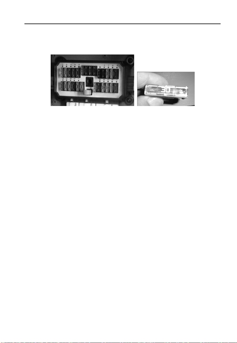
Fuse box
The fuse box is in a compar t me nt that under the driver’s area.
Electrical part
88
Page 91

Electrical part
Connecting position
The ceiling wire harness c onnects with instrument s w ire harness
in the compartment under the auxiliary dashboard.
The chassis wire harness connects with instrument wire harness
under the glove compar tment near the front door.
89
 Loading...