

01:02 Issue 10 en-GB
© Scania CV AB 2018, Sweden
Installation manual
Intake system and ventilation
Industrial engines
DC09, DC13, DC16
OC16

INSTALLATION
MANUAL
© Scania CV AB 2018, Sweden
01:02 Issue 10 en-GB 2
Changes from the previous issue............................................................................3
Intake air ..................................................................................................................4
Intake air taken from outside engine room.......................................................... 5
Intake air taken from engine room ...................................................................... 8
Ventilation requirements for gas engines..............................................................9
Air cleaner..............................................................................................................10
Air cleaners with precleaner.............................................................................. 11
Air cleaners without precleaner......................................................................... 12
Crankcase ventilation............................................................................................13
Open crankcase ventilation ............................................................................... 13
Closed crankcase ventilation............................................................................. 14
Connection to turbocharger .................................................................................15
Cleanliness requirements................................................................................... 15
Charge air pipe .................................................................................................. 15
Stage IV/Tier 4f engines ................................................................................... 16
Important data.......................................................................................................20

INSTALLATION
MANUAL
© Scania CV AB 2018, Sweden
Changes from the previous issue
01:02 Issue 10 en-GB 3
Changes from the previous issue
The changes made in this document compared with the previous issue are marked
with a line in the left-hand margin. The changes are also described below.
• Max. permissible vacuum in the intake system has been changed to 40 mbar for
16 litre single-speed engines. See Intake air taken from outside engine room
.
• Max. permissible vacuum in the engine compartment for engines without fan
(1 mbar) has been removed. 2 mbar now applies to all engines. See Intake air tak-
en from engine room.
• Safety cartridges are no longer included with air cleaners with precleaners. Safety
cartridges can instead be purchased as an option. See Air cleaner
.
• Clearances for Air cleaners with precleaner
and Air cleaners without precleaner
have been corrected.
• Section Important data
has been added.
INSTALLATION
MANUAL
© Scania CV AB 2018, Sweden
Intake air
01:02 Issue 10 en-GB 4
Intake air
If the intake line is located close to exhaust pipes or other hot parts, radiation protection should be used to limit unnecessary heating of the intake air.
REQUIREMENT!
The intake air temperature may not exceed the ambient temperature by more than
5°C for Stage IV/Tier 4f engines, or 10°C for other engines.
Measure the temperature when the installation is complete. Refer to 01:08 Measur-
ing instructions for installation inspection.
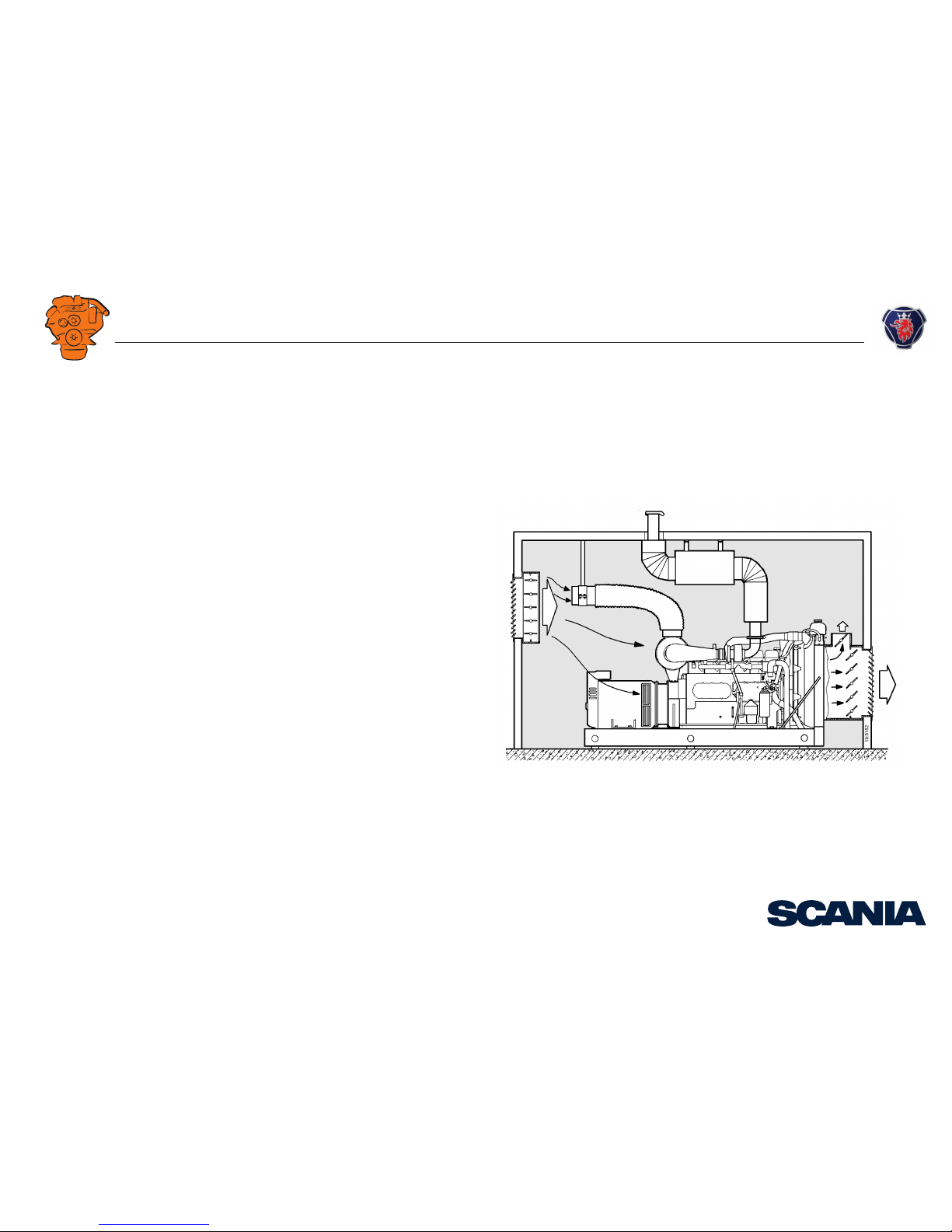
If the intake air temperature upstream of the turbocharger continuously exceeds
30°C, then engine power may drop. If the engine is enclosed in some manner, make
sure that there is an adequate flow of intake air.
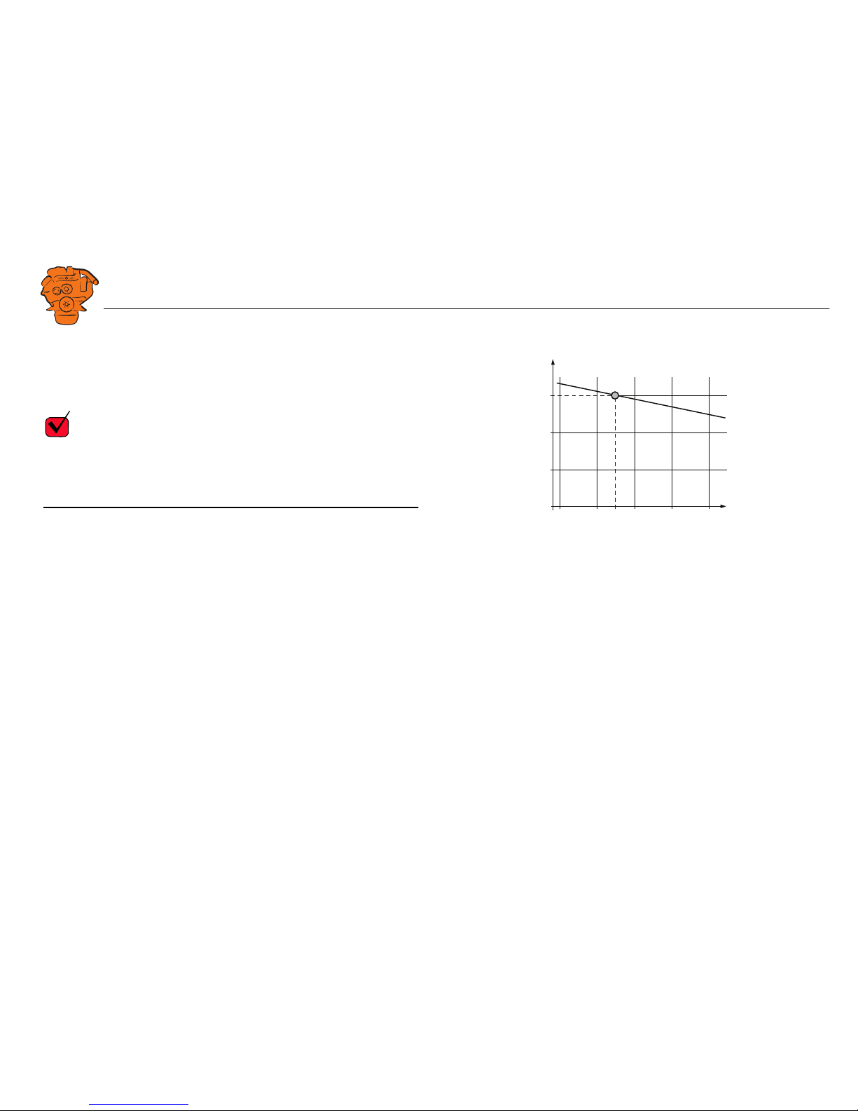
The dependence of the engine power on intake air temperature is shown in the chart
on the right. This diagram is only valid for DC engines. 100% engine power is shown
under actual test conditions at the factory.
Gas engines can be subject to significant power loss if the intake air to the turbocharger has a high temperature in combination with the fuel having a low MN value
(knock-sensitive fuel).
The engine air consumption in kg/min at full power and at different engine speeds is
indicated in the tables showing the air consumption and radiated heat for the relevant
engine type in 01:06 Technical data.
100
95
90
%
A
B
10 20 302540 50
°C
340 422
Engine power dependence on intake air temperature. 100 % at 25°C, 1,000 mbar, engine power setting not corrected.
This diagram is only valid for DC engines.
A = Engine power.
B = Intake air temperature.

INSTALLATION
MANUAL
© Scania CV AB 2018, Sweden
Intake air
01:02 Issue 10 en-GB 5
Intake air taken from outside engine room
In engine systems where the engine intake air comes from outside the engine room
and is led via a fresh air line to the engine, the vacuum for the intake system should
be measured.
The air intake should be located so that the intake air is as clean as possible and so
that neither the engine exhaust gases nor heated air from the engine room can mix
with the intake air. The air intake should be designed to exclude water, snow and contamination.
The intake air must not contain chemical pollutants, such as CFCs.
REQUIREMENT!
The maximum permissible vacuum in the intake system is 30 mbar. For 16 litre single-speed engines, a vacuum of 40 mbar is permissible. This value includes the vacuum in the new air filter, connected coarse filter and in the fresh air line.
Measure the vacuum when the installation is complete. Refer to 01:08 Measuring in-
structions for installation inspection.

INSTALLATION
MANUAL
© Scania CV AB 2018, Sweden
Intake air
01:02 Issue 10 en-GB 6
The following applies to the fresh air line:
• The fresh air line must not be routed with any sharp bends.
• The inside of the fresh air line must be flat and even.
• If a hose is used as a fresh air line, it must be rigid enough that it does not collapse
onto itself.
It is not necessary to check the vacuum in the following cases:
• If the intake system is comprised of air hoses and air pipes from Scania's standard
range.
• If the fresh air line is maximum 5 m and has an inside diameter of at least 160 mm
for DC09 or 210 mm for DC13 and DC16, respectively.
If the planned fresh air line is longer than 5 m, the required diameter must be calculated as illustrated. The vacuum upstream of the turbocharger must then be measured.
Refer to 01:08 Measuring instructions for installation inspection.
REQUIREMENT!
The total vacuum in the intake system with a blocked air filter must not exceed
65 mbar.
Engine damage will not occur up to 100 mbar, but fuel consumption and smoke will
increase. Above 100 mbar there is a risk that the air volume to the engine will be inadequate, resulting in breakdowns.
B (kg/min)
365 744
A (mm)
500
400
300
200
100
0
0
10 20 30 40 50 60
25 m
50 m
Calculation of minimum diameter of the intake line.
A = Intake line diameter.
B = Air consumption.
 Loading...