

Page 1

CAN interface for bodywork
More information on connections is found under Connections.
Introduction
External CAN bus
The CAN bus that connects to the CAN interface for bodywork equipment is called
the external CAN bus below.
CAN interface
The interface with the bodywork consists of a number of connectors which have been
prepared with signals and functions. In vehicles equipped with the optional preparation bodywork control unit (BWS), this interface includes a CAN connection for
bodywork equipment, connector C259, pins 20 and 21.
Bodywork control unit BWS
The bodywork control unit transmits CAN messages from the internal CAN network
of the vehicle to the CAN interface for forwarding to the CAN network of the bodywork equipment. The bodywork control unit receives a number of defined messages
used to activate bodywork functions in the vehicle from the bodywork equipment
CAN network.
Introduction
The protocol used is based on SAE J1939.
• A summary of the available CAN messages in the external CAN bus is contained
under the heading Summary of CAN messages. This also lists the vehicles (chassis serial numbers) for which the various messages are applicable.
• Detailed information about each CAN message is contained under the heading
Detailed description of CAN messages.
• Detailed requirements for CAN communication with the bodywork control unit
in the external CAN bus are contained under the heading Requirements for CAN
communication with the vehicle.
11:90-01 Issue 1 en-GB 1 (139)
©
Scania CV AB 2013, Sweden
Page 2
CAN interface for bodywork
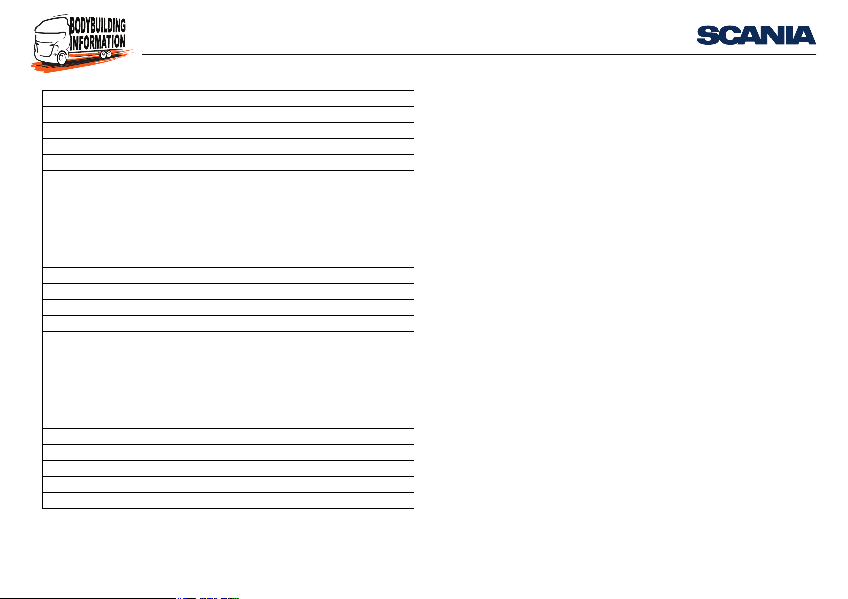
Abbreviation Designation
ABS Anti-lock Brake System
AICC Adaptive Cruise Control
APS Air Processing System
BAM Broadcast Announce Message
BMS Brake Management System
BWS Body Work System
CAN Controller Area Network
COO Coordinator
CUV Control Unit Visibility
EEC Electronic Engine Control
ECU Electronic Control Unit
EMS Engine Management System
EOBD Emission related On-Board Diagnostic
GMS Gearbox Management System
HPI High Pressure Injection
ICL Instrument Cluster System
LAS Locking and Alarm System
LHD Left Hand Drive
OBD On-Board Diagnostic
PGN Parameter Group Number
PTO Power Take-Off
RET Retarder
SMS Suspension Management System
TCO Tachograph
TP.CM Transport Protocol Connection Management
Introduction
11:90-01 Issue 1 en-GB 2 (139)
©
Scania CV AB 2013, Sweden
Page 3
CAN interface for bodywork
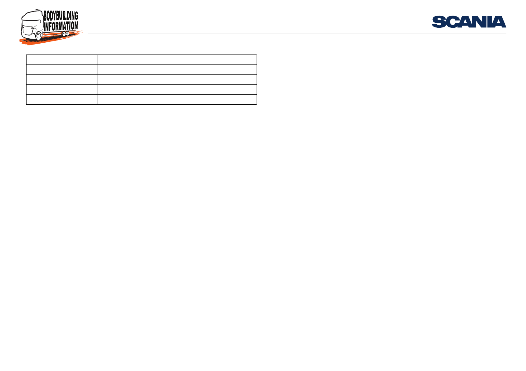
Abbreviation Designation
TP.DT Transport Protocol Data Transfer
RTI Road Transport Informatics System
RHD Right Hand Drive
VIS Visibility System
Introduction
11:90-01 Issue 1 en-GB 3 (139)
©
Scania CV AB 2013, Sweden
Page 4

CAN interface for bodywork
Summary of CAN messages
Explanation
The following is a summary of the messages which the CAN interface for the bodywork equipment supports, including the date of their introduction.
In addition to the PGNs specified in SAE J1939-71 (Vehicle Application Layer),
there are a number of PGNs specified by Scania.
The last two characters in the identifier indicate which control unit sends the message. See the Source addresses table.
Summary of CAN messages
11:90-01 Issue 1 en-GB 4 (139)
©
Scania CV AB 2013, Sweden
Page 5
CAN interface for bodywork
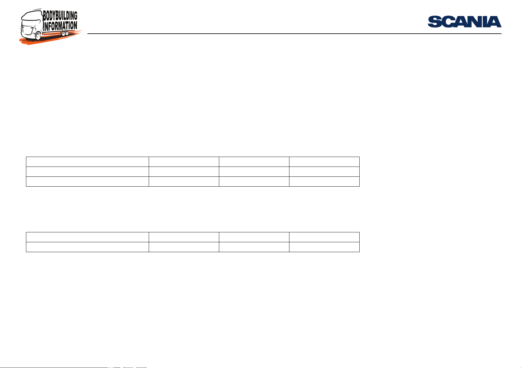
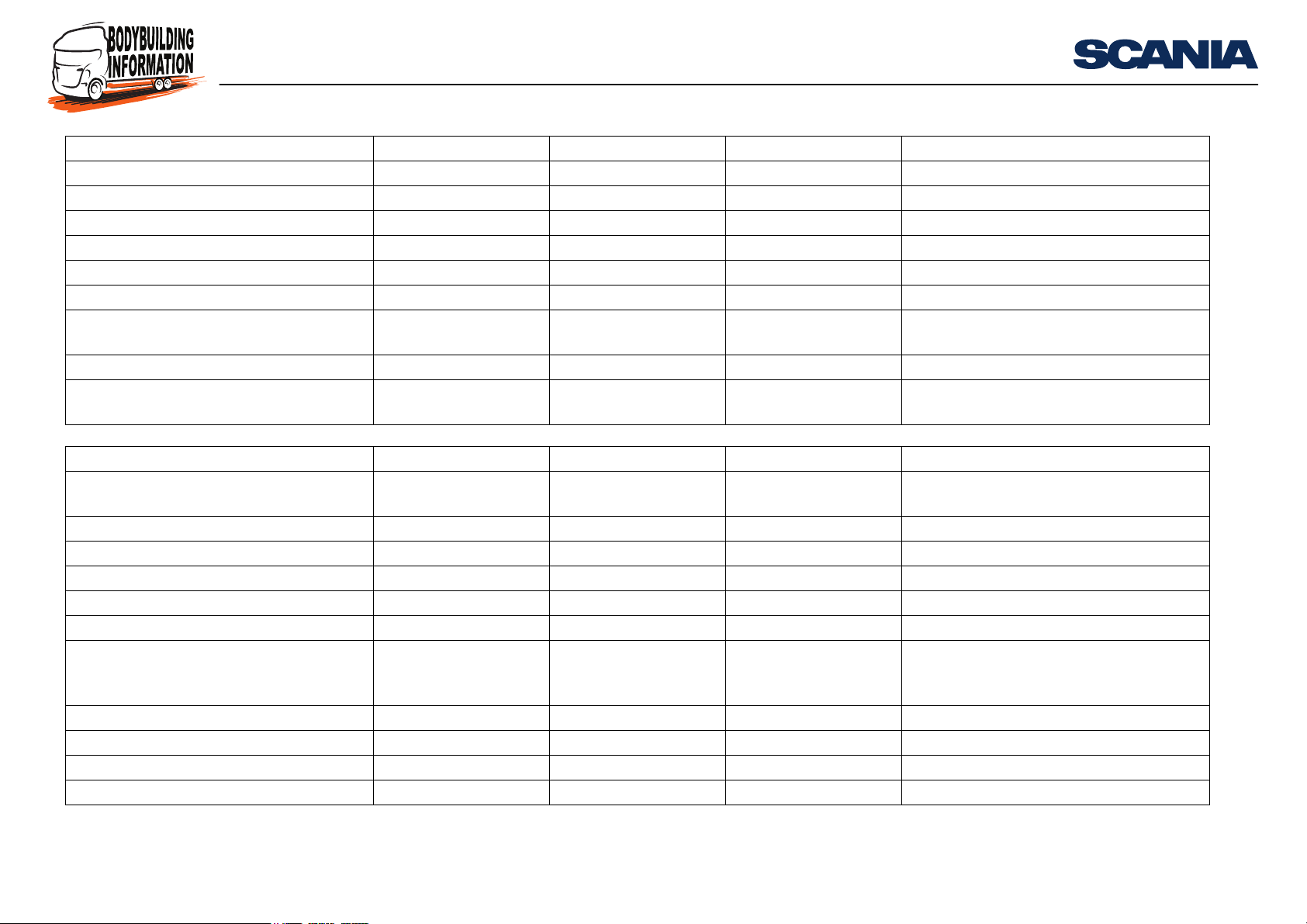
CAN messages sent to the vehicle
The bodywork control unit receives the CAN messages on the external CAN bus.
These messages are used to activate bodywork functions in the vehicle.
Vehicle production period
Production site Chassis serial number
2005-10-21 -
Södertälje 2 011 987 -
Zwolle 5 133 666 -
Angers 9 104 286 -
Message to vehicle Identifier (Hex) Source address Specification
a
Scania Bodywork Control Message 1 0C
Scania Bodywork Control Message 2 0C
a. Recommended values may vary depending on the bodybuilder's own prioritisation on the external CAN bus.
b. Optional according to the SAE J1939 standard, but do not use the address 2E (Hex), which is the source address for the bodywork control unit.
FF F8 XX
a
FF F9 XX
b
b
XScania
XScania
Summary of CAN messages
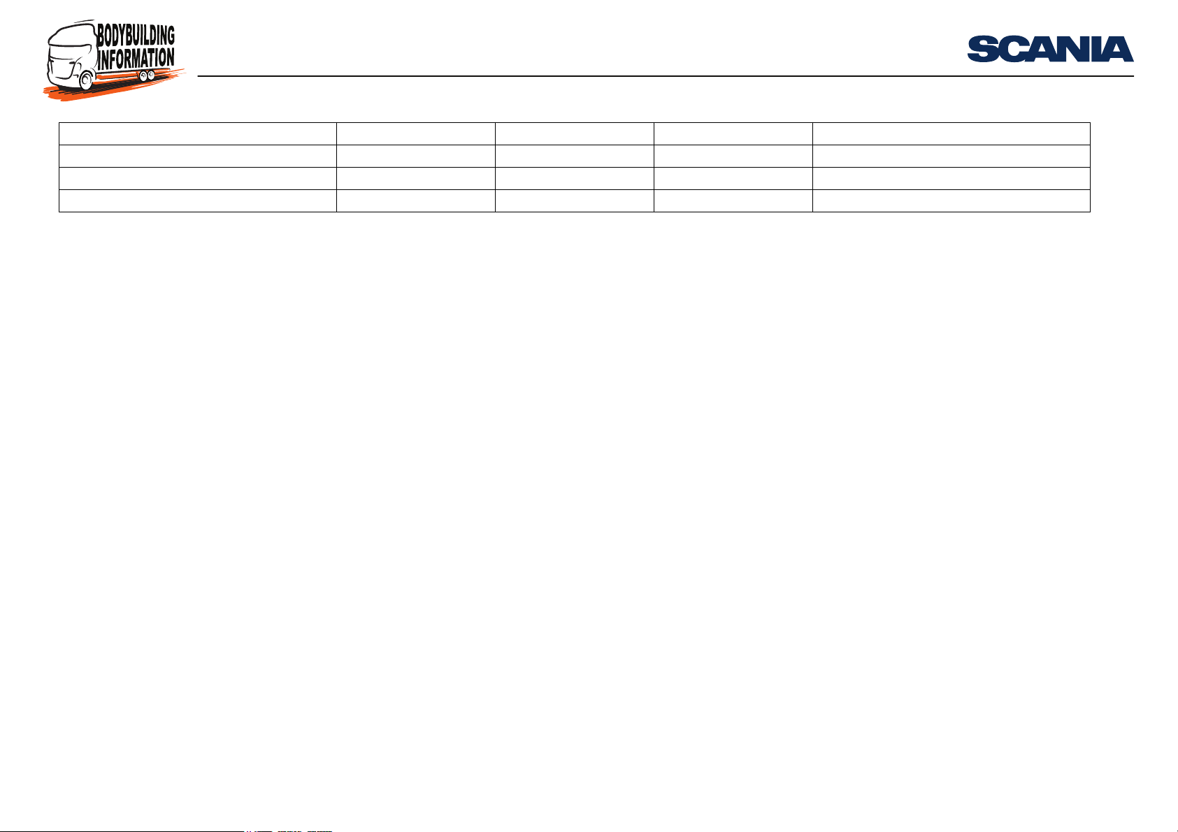
The following CAN messages can be received by vehicles manufactured from October 2008 onwards:
Message to vehicle Identifier (Hex) Source address Specification
Scania Bodywork Control Message 3 0C
a. Recommended values may vary depending on the bodybuilder's own prioritisation on the external CAN bus.
b. Optional according to the SAE J1939 standard, but do not use the address 2E (Hex), which is the source address for the bodywork control unit.
11:90-01 Issue 1 en-GB 5 (139)
a
FF E6 XX
b
XX Scania
©
Scania CV AB 2013, Sweden
Page 6
CAN interface for bodywork
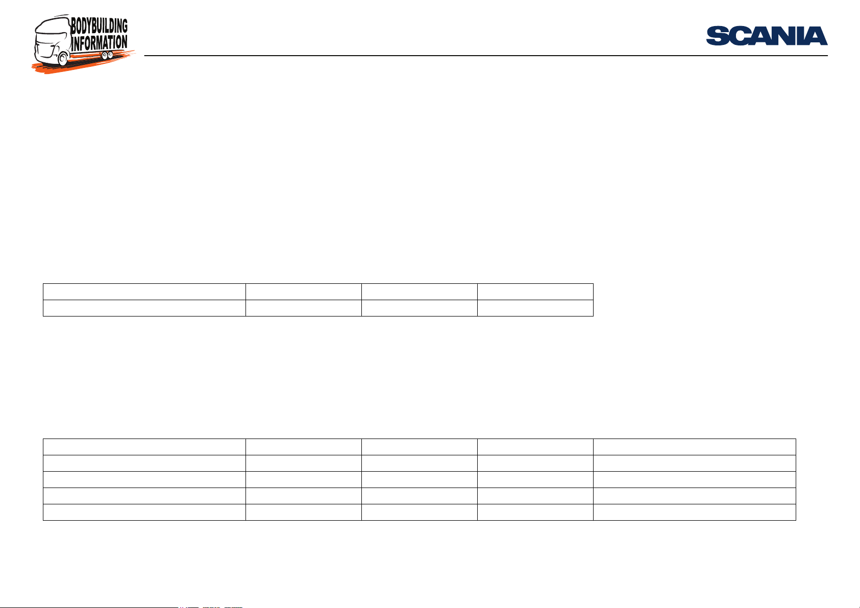
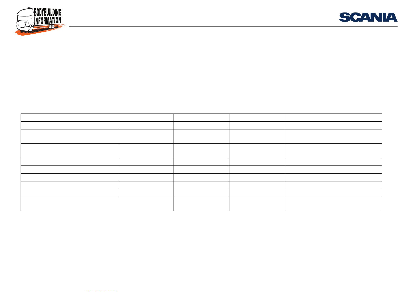
CAN message sent from the vehicle
The bodywork control unit sends the Software Identification message to the external
CAN bus to identify the CAN interface version. It is important to identify the version
which is applicable to the vehicle in order to interpret the CAN messages which are
sent from the vehicle and to know which commands can be sent to the vehicle.
Vehicle production period
Production site Chassis serial number
2005-10-21 -
Södertälje 2 011 987 -
Zwolle 5 133 666 -
Angers 9 104 286 -
Message to vehicle Identifier (Hex) Source address Specification
Software identification 18 FE DA 2E BWS SAE J1939-71
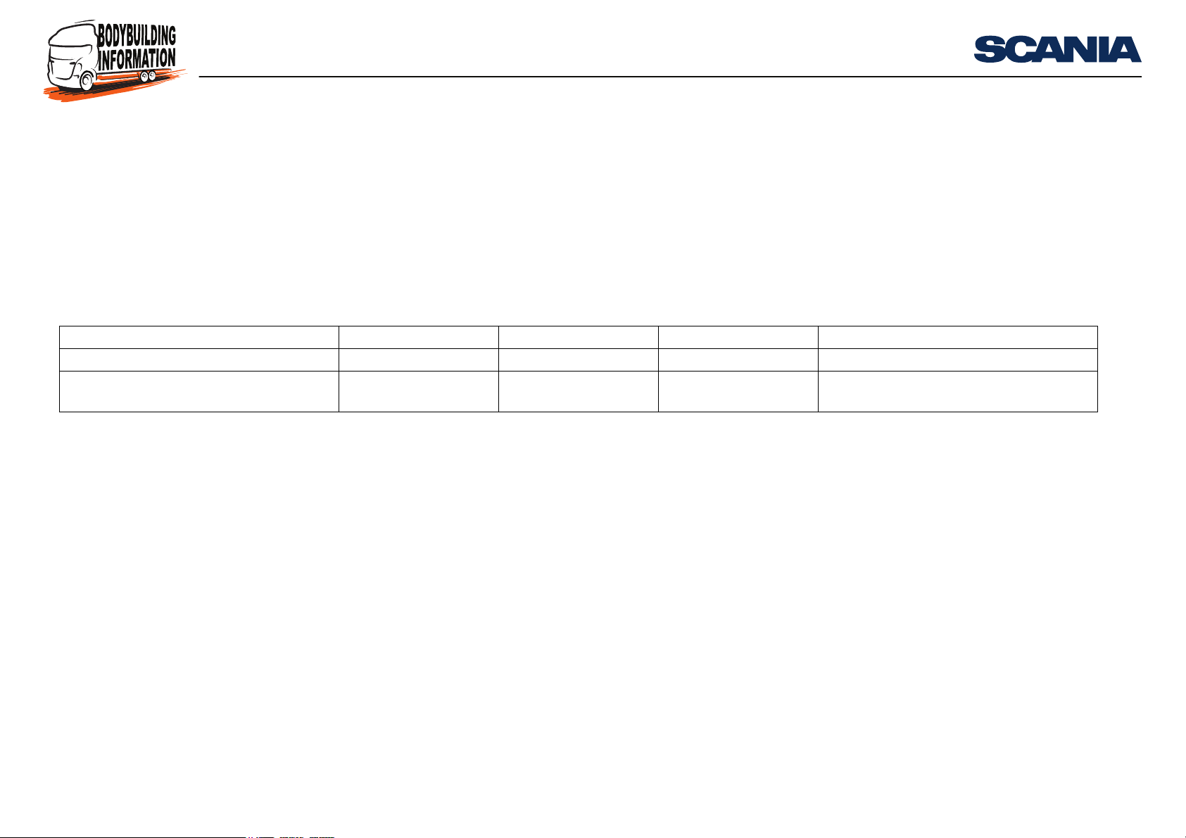
Vehicle production period
Production site Chassis serial number
2005-01-21 -
Södertälje 2 006 429 -
Zwolle 5 117 958 -
Angers 9 097 244 -
Summary of CAN messages
Message to vehicle Identifier (Hex) Source address Specification Remarks
EEC1 0C F0 04 00 EMS SAE J1939-71
EEC2 0C F0 03 00 EMS SAE J1939-71
Engine Temperature 18 FE EE 00 EMS SAE J1939-71
Engine Hours, Revolutions 18 FE E5 00 EMS SAE J1939-71
11:90-01 Issue 1 en-GB 6 (139)
©
Scania CV AB 2013, Sweden
Page 7
CAN interface for bodywork
Summary of CAN messages
Message to vehicle Identifier (Hex) Source address Specification Remarks
Fuel Consumption 18 FE E9 00 EMS SAE J1939-71
Fuel Economy 18 FE F2 00 EMS SAE J1939-71
CC/Vehicle speed 18 FE F1 00 EMS SAE J1939-71
Inlet/Exhaust cond. 18 FE F6 00 EMS SAE J1939-71
BAM-E 18 EC FF 00 EMS SAE J1939-71
Engine Configuration Messages 18 EB FF 00 EMS SAE J1939-71
ETC1 0C F0 02 03 SAE J1939-71 Only sent if the vehicle has Opticruise or an
Allison automatic gearbox
ETC2 18 F0 05 03 SAE J1939-71
Transmission fluid 18 FE F8 03 SAE J1939-71 Only sent if the vehicle has an Allison gear-
box
Message to vehicle Identifier (Hex) Source address Specification Remarks
ERC1-RD 18 F0 00 10 RET SAE J1939-71 Only sent if the vehicle has a Retarder or an
Allison automatic gearbox
EAC1-K 18 F0 06 27 COO SAE J1939-71
Ambient Conditions 18 FE F5 27 COO SAE J1939-71
Dash Display 18 FE FC 27 COO SAE J1939-71
Engine Fluid Level/Pressure 18 FE EF 27 COO SAE J1939-71
Supply Pressure 18 FE AE 30 APS SAE J1939-71
Vehicle Weight 18 FE EA 2F SMS SAE J1939-71 Only sent if the vehicle has SMS and is
equipped with pressure sensors in the bellows
TCO1 0C FE 6C EE TCO SAE J1939-71
High Resolution Vehicle Distance 18 FE C1 EE TCO SAE J1939-71
Illumination 18 D0 FF 17 ICL SAE J1939-71
Time/Date 18 FE E6 17 ICL SAE J1939-71
11:90-01 Issue 1 en-GB 7 (139)
©
Scania CV AB 2013, Sweden
Page 8
CAN interface for bodywork
Summary of CAN messages
Message to vehicle Identifier (Hex) Source address Specification Remarks
EBC1 18 F0 01 0B BMS SAE J1939-71
EBC4 Wheel Brake Lining Remaining 1C FE AC 0B BMS SAE J1939-71 Only sent if the vehicle has EBS
DM1 18 FE CA XX
a. XX (Hex) varies depending on which control unit sends the message.
a
Varies SAE J1939-73
11:90-01 Issue 1 en-GB 8 (139)
©
Scania CV AB 2013, Sweden
Page 9
CAN interface for bodywork
Summary of CAN messages
The CAN messages can be sent by vehicles with the following chassis serial numbers, see following table:
Vehicle production period
Production site Chassis serial number
2005-10-21 -
Södertälje 2 011 987 -
Zwolle 5 133 666 -
Angers 9 104 286 -
Message to vehicle Identifier (Hex) Source address Specification Remarks
DLN2-Proprietary 0C FF 81 00 EMS Scania
Transmission Proprietary 2 18 FF A1 03 GMS Scania Only sent if the vehicle has Opticruise or a
manual gearbox
Retarder fluids 18 FE FB 10 GMS SAE J1939-71 Only sent if the vehicle has an Allison gear-
box
Transmission Proprietary/DLN5 18 FF A0 27 COO Scania
Coordinator General Information 0C FF B0 27 COO Scania
Coordinator General Information2 0C FF AF 27 COO Scania
PTO information 18 FF 90 27 COO Scania Only sent if the vehicle has a power take-off
CUV information 18 FF B1 1E VIS Scania
Alarm status proprietary 18 FF B4 1D LAS Scania Only sent if the vehicle has an alarm system
(LAS)
11:90-01 Issue 1 en-GB 9 (139)
©
Scania CV AB 2013, Sweden
Page 10
CAN interface for bodywork
Summary of CAN messages
The CAN messages can be sent by vehicles with the following chassis serial numbers, see following table:
Vehicle production period
Production site Chassis serial number
2007-02-28 -
Södertälje 2 024 649 -
Zwolle 5 169 578 -
Angers 9 118 703 -
Message to vehicle Identifier (Hex) Source address Specification Remarks
Scania bodywork status message1 0C FF E8 2E BWS Scania
ETC7 18 FE 4A 03 GMS SAE J1939-71 Only sent if the vehicle has an Allison gear-
box
11:90-01 Issue 1 en-GB 10 (139)
©
Scania CV AB 2013, Sweden
Page 11
CAN interface for bodywork
The following CAN messages can be sent by vehicles manufactured from September
2008 onwards:
Message to vehicle Identifier (Hex) Source address Specification Remarks
Air supply pressure 18 FE AE 30 APS SAE J1939-71
Air suspension control 1 0C FE 5A 27 COO SAE J1939-71
Cab information proprietary 1 18 FF 96 17 ICL Scania
Crash occurred 18 FF FD 64 CSS Scania
DLN5 18 FF A0 27 COO Scania
DLN8 18 FF 88 00 EMS Scania
EBC2 Wheel speed proprietary 0C FF 19 0B BMS Scania
EBC5 18 FD C4 0B BMS SAE J1939-71
ETC1 - CV 0C F0 02 43 GMS SAE J1939-71 ZF torque converter
Engine Configuration Messages 18 EC FF 00 EMS SAE J1939-71
Transmission Control 1 0C 01 FF 05 COO SAE J1939-71
Transmission Proprietary 2 - AWD 18 FF A1 04 AWD Scania AWD equipped
Transport Protocol - ConnectionManagement
Transport Protocol - Data Transfer 18 EB FF 00 EMS SAE J1939-71
Vehicle Weight - ICL 18 FE EA 17 ICL SAE J1939-71
18 EC FF 00 EMS SAE J1939-71
Summary of CAN messages
11:90-01 Issue 1 en-GB 11 (139)
©
Scania CV AB 2013, Sweden
Page 12

CAN interface for bodywork
Detailed description of CAN messages
Explanation
The following tables use the concepts below.
For the content of messages with PGNs specified in SAE J1939:
• Not defined (not defined in SAE J1939)
• Not used (defined in SAE J1939, but not used by Scania)
For the content of messages with PGNs specified by Scania:
• Not defined (not defined by Scania)
Detailed description of CAN messages
11:90-01 Issue 1 en-GB 12 (139)
©
Scania CV AB 2013, Sweden
Page 13
CAN interface for bodywork
Detailed description of CAN messages
CAN messages sent to the vehicle
Scania Bodywork Control Message 1
Identifier: 0C FF F8 XX
Transmission interval: 50 ms
Byte Bit Length Explanation State Resolution Limits Note
118Message configuration version 01h 0 to 250
212Engine control mode
Engine speed control disabled 00 C
Engine speed control 1 01
Engine speed control 2 10
Not available or not installed 11
3..4 Not defined
52Requested governor
Normal governor 00
Stiff governor 01
Error indicator 10
Not available or not installed 11
72Accelerator pedal disable
Accelerator pedal not disabled 00
Accelerator pedal disabled 01
Error indicator 10
Not available 11
316Requested engine speed 0.125 r/min 0 to 8 031.875 r/min B
Error indicator FExxh
Not available FExxh
11:90-01 Issue 1 en-GB 13 (139)
©
Scania CV AB 2013, Sweden
Page 14
CAN interface for bodywork
Detailed description of CAN messages
Byte Bit Length Explanation State Resolution Limits Note
5 Not defined
612Retardate A
Retardation not requested 00
Retardation requested 01
Error indicator 10
Not available or not installed 11
32Accelerate A
“Accelerate" not requested 00
“Accelerate" requested 01
Error indicator 10
Not available or not installed 11
52Resume A
“Resume” not requested 00
“Resume” requested 01
Error indicator 10
Not available or not installed 11
7..8 Not defined
7..8 Not defined
A: Active when Engine Speed Control 1 is selected.
B: Active when Engine Speed Control 2 is selected.
C: For version 1 of the external CAN interface Engine control mode must be set to
00b in a number of samples when switching between Engine Speed Control 1 and 2.
It is not necessary from version 2 onwards.
11:90-01 Issue 1 en-GB 14 (139)
©
Scania CV AB 2013, Sweden
Page 15
CAN interface for bodywork
Detailed description of CAN messages
Scania Bodywork Control Message 2
Identifier: 0C FF F9 XX
Transmission interval: 100 ms
Byte Bit Length Explanation State Resolution Limits Note
118Message configuration version 02h 0 to 250 A
212Increased idle speed switch 1 (ISSW1) B
ISSW1 not demanded 00
ISSW1 demanded 01
Error indicator 10
Not available or not installed 11
32Increased idle speed switch 2 (ISSW2) C
ISSW2 not demanded 00
ISSW2 demanded 01
Error indicator 10
Not available or not installed 11
5..8 Not defined
312Second vehicle speed limiter
Speed limit not requested 00
Speed limit requested 01
Error indicator 10
Not available or not installed 11
3..4 Not defined
52Torque limit 1
Torque limit 1 not requested 00
Torque limit 1 requested 01
Error indicator 10
11:90-01 Issue 1 en-GB 15 (139)
©
Scania CV AB 2013, Sweden
Page 16

CAN interface for bodywork
Detailed description of CAN messages
Byte Bit Length Explanation State Resolution Limits Note
Not available or not installed 11
72Torque limit 2
Torque limit 2 not requested 00
Torque limit 2 requested 01
Error indicator 10
Not available or not installed 11
412Engine start
Engine start not requested 00
Engine start requested 01
Error indicator 10
Not available or not installed 11
Not defined
3..4 Monitored engine stop
5 2 Monitored engine stop not requested 00
Monitored engine stop requested 01
Error indicator 10
Not available or not installed 11
7..8 Not defined
512PTO1/external equipment 1 activation
External equipment 1 not requested 00
External equipment 1 requested 01
Error indicator 10
Not available or not installed 11
32PTO2/external equipment 2 activation
External equipment 2 not requested 00
External equipment 2 requested 01
11:90-01 Issue 1 en-GB 16 (139)
©
Scania CV AB 2013, Sweden
Page 17

CAN interface for bodywork
Detailed description of CAN messages
Byte Bit Length Explanation State Resolution Limits Note
Error indicator 10
Not available or not installed 11
52PTO3/external equipment 3 activation
External equipment 3 not requested 00
External equipment 3 requested 01
Error indicator 10
Not available or not installed 11
7..8 Not defined
612Horn activation
Horn not requested 00
Horn requested 01
Error indicator 10
Not available or not installed 11
32Main beam activation
Main beam not requested 00
Main beam requested 01
Error indicator 10
Not available or not installed 11
52Hazard lamp activation
Hazard lamp not requested 00
Hazard lamp requested 01
Main beam requested 10
Not available or not installed 11
72Buzzer activation
Buzzer not requested 00
Buzzer requested 01
11:90-01 Issue 1 en-GB 17 (139)
©
Scania CV AB 2013, Sweden
Page 18
CAN interface for bodywork
Detailed description of CAN messages
Byte Bit Length Explanation State Resolution Limits Note
Main beam requested 10
Not available or not installed 11
Wiper activation
7 1 2 Wiper not requested 00
Wiper requested 01
Main beam requested 10
Not available or not installed 11
32Work light control D
Work light off requested 00
Work light on requested 01
Error indicator 10
Not available or not installed 11
52Constant engine speed limit request E
Engine speed limit not requested 00
Engine speed limit requested 01
Reserved 10
Take no action 11
72Automatic neutral request 0 - 3 F
Automatic neutral not requested 00
Automatic neutral requested 01
Reserved 10
Not available 11
8 Not defined
A: Enter the correct version of the message here.
11:90-01 Issue 1 en-GB 18 (139)
©
Scania CV AB 2013, Sweden
Page 19

CAN interface for bodywork
B: Used to activate the Limited hand throttle and Pre-defined (locked) engine speed
functions.
C: Used to activate the Raised idling speed and Pre-defined (locked) engine speed
functions.
D: Only applicable if the CAN interface version is 2 or higher. Version number can
be read from the CAN message Software Identification. Note: Byte 1, Message Configuration Version, must be set to 02h so that the control unit can interpret the Work
light control command.
E: Only applicable if the CAN interface version is 3 or higher.
F: Only applicable if the CAN interface version is 4 or higher.
Detailed description of CAN messages
11:90-01 Issue 1 en-GB 19 (139)
©
Scania CV AB 2013, Sweden
Page 20

CAN interface for bodywork
Detailed description of CAN messages
Scania Bodywork Control Message 3
Identifier: 0C FF E6 XX
Transmission interval: 100 ms
Byte Bit Length Explanation State Resolution Limits Note
118Message configuration version 01h 1 0 to 250 A
212Driver information request 1 1B
Driver information not requested 00
Driver information requested 01
Error indicator 10
Not available or not installed 11
32Driver information request 2 1B
Driver information not requested 00
Driver information requested 01
Error indicator 10
Not available or not installed 11
52Driver information request 3 1B
Driver information not requested 00
Driver information requested 01
Error indicator 10
Not available or not installed 11
72Driver information request 4 B
Driver information not requested 00
Driver information requested 01
Error indicator 10
Not available or not installed 11
312Driver information request 5 1B
11:90-01 Issue 1 en-GB 20 (139)
©
Scania CV AB 2013, Sweden
Page 21

CAN interface for bodywork
Detailed description of CAN messages
Byte Bit Length Explanation State Resolution Limits Note
Driver information not requested 00
Driver information requested 01
Error indicator 10
Not available or not installed 11
32Driver information request 6 1B
Driver information not requested 00
Driver information requested 01
Error indicator 10
Not available or not installed 11
52Driver information request 7 1B
Driver information not requested 00
Driver information requested 01
Error indicator 10
Not available or not installed 11
72Driver information request 8 B
Driver information not requested 00
Driver information requested 01
Error indicator 10
Not available or not installed 11
422Driver information request 9 1B
Driver information not requested 00
Driver information requested 01
Error indicator 10
Not available or not installed 11
32Driver information request 10 1B
Driver information not requested 00
11:90-01 Issue 1 en-GB 21 (139)
©
Scania CV AB 2013, Sweden
Page 22
CAN interface for bodywork
Detailed description of CAN messages
Byte Bit Length Explanation State Resolution Limits Note
Driver information requested 01
Error indicator 10
Not available or not installed 11
5116Requested vehicle speed limit 0.00390625 0 - 250.996 C
No request 0xFB00
Error indicator 0xFExx
Not available or not installed 0xFFxx
7..8 Not defined
A: Enter the correct version of the message here. This is version 1.
B: Signal which activates indicator lamps for bodywork functions or sound in the instrument cluster.
C: Part of UF 117 Third speed limiter.
11:90-01 Issue 1 en-GB 22 (139)
©
Scania CV AB 2013, Sweden
Page 23
CAN interface for bodywork
Detailed description of CAN messages
CAN messages sent from the vehicle
Software identification
Identifier: 18 FE DA 2E
Transmission interval: 1,000 ms
Always sent from BWS.
Byte Bit Length Explanation State Resolution Limits Note
118Number of software identification fields 01h A
Error FEh
Not available FFh
118Software identification ASCII B
3 1 8 Delimiter 2 Ah C
4..8 Not defined
A: Only one identifier is used.
B: Note: The identifier only indicates, in ASCII format, the CAN interface version,
not the software. Example: 31h=ASCII "1".
C: The message ends with the ASCII character for "*".
Chassis serial numbers for the different versions of the external CAN interface:
Vehicle production period for version 1:
Production site Chassis serial number
2005-10-13 - 2007-02-27
Södertälje 2 011 780 - 2 024 648
Zwolle 5 133 079 - 5 168 577
Angers 9 104 037 - 9 118 702
11:90-01 Issue 1 en-GB 23 (139)
©
Scania CV AB 2013, Sweden
Page 24

CAN interface for bodywork
Vehicle production period for version 2:
Production site Chassis serial number
2007-02-28 -
Södertälje 2 024 649 -
Zwolle 5 169 578 -
Angers 9 118 703 -
Detailed description of CAN messages
11:90-01 Issue 1 en-GB 24 (139)
©
Scania CV AB 2013, Sweden
Page 25
CAN interface for bodywork
Detailed description of CAN messages
Scania bodywork status message 1
Byte Bit Length Explanation State Resolution Limits Note
112EXT active
EXT not active 00
EXT active 01
3..8 Not defined
213Torque limiter
Torque limiter disabled 000
Torque limit 1 001
Torque limit 2 010
Torque limit 3 011
Not available or not installed 111
312Vehicle speed limiter
Vehicle speed limiter 1 00
Vehicle speed limiter 2 01
3..8 Not defined
4..8 Not defined
11:90-01 Issue 1 en-GB 25 (139)
©
Scania CV AB 2013, Sweden
Page 26

CAN interface for bodywork
Detailed description of CAN messages
Air Supply Pressure
Identifier: 18 FE AE 30
Transmission interval: 1,000 ms
Byte Bit Length Explanation State Resolution Limits Note
118Pneumatic supply pressure 8 0 to 2000 kPa A
Error indicator FE
Not available FF
218Parking and/or trailer air pressure 8 0 to 2000 kPa
Error indicator FE
Not available FF
318Service brake air pressure, circuit1 8 0 to 2000 kPa
Error indicator FE
Not available FF
418Service brake air pressure, circuit2 8 0 to 2000 kPa B
Error indicator FE
Not available FF
518Auxiliary equipment supply pressure 8 0 to 2000 kPa
Error indicator FE
Not available FF
618Air suspension supply pressure 8 0 to 2000 kPa
Error indicator FE
Not available FF
712Air compressor status1
Compressor not active 00
Compressor active 01
Error 10
11:90-01 Issue 1 en-GB 26 (139)
©
Scania CV AB 2013, Sweden
Page 27
CAN interface for bodywork
Detailed description of CAN messages
Byte Bit Length Explanation State Resolution Limits Note
Not available 11
A: Only received for advanced APS.
B: Rear circuit.
11:90-01 Issue 1 en-GB 27 (139)
©
Scania CV AB 2013, Sweden
Page 28

CAN interface for bodywork
Detailed description of CAN messages
Air Suspension Control 1
Identifier: 0C FE 5A 27
Transmission interval: 100 ms
Byte Bit Length Explanation State Resolution Limits Note
114Nominal level front axle 0 to 15
Level not specified 0000
Normal level 1 0001
Normal level 2 0010
Normal level 3 0011
Preset level 0100
Customer level 0101
Upper level 0110
Lower level 0111
Error 1110
Not available 1111
54Nominal level rear axle 0 to 15
Level not specified 0000
Normal level 1 0001
Normal level 2 0010
Normal level 3 0011
Preset level 0100
Customer level 0101
Upper level 0110
Lower level 0111
Error 1110
Not available 1111
11:90-01 Issue 1 en-GB 28 (139)
©
Scania CV AB 2013, Sweden
Page 29
CAN interface for bodywork
Detailed description of CAN messages
Byte Bit Length Explanation State Resolution Limits Note
212Below nominal level front axle 0 to 3
Not below 00
Below 01
Error 10
Not available 11
32Below nominal level rear axle 0 to 3
Not below 00
Error 01
Below 10
Not available 11
52Above nominal level front axle 0 to 3
Not above 00
Above 01
Error 10
Not available 11
72Above nominal level rear axle 0 to 3
Not above 00
Above 01
Error 10
Not available 11
312Lowering control mode front axle 0 to 3
Lowering not active 00
Lowering active 01
Error 10
Not available 11
32Lowering control mode rear axle 0 to 3
11:90-01 Issue 1 en-GB 29 (139)
©
Scania CV AB 2013, Sweden
Page 30

CAN interface for bodywork
Detailed description of CAN messages
Byte Bit Length Explanation State Resolution Limits Note
Lowering not active 00
Lowering active 01
Error 10
Not available 11
52Lifting control mode front axle 0 to 3
Lifting not active 00
Lifting active 01
Error 10
Not available 11
72Lifting control mode rear axle 0 to 3
Lifting not active 00
Lifting active 01
Error 10
Not available 11
414Kneeling information 0 to 15
Kneeling not active 0000
Kneeling active 0001
Kneeling level reached 0010
Lifting active 0011
Kneeling aborted 0100
Error 1110
Not available 1111
54Level control mode 0 to 15
Normal operation 0000
Traction help (Load transfer) 0001
Load fixing 0010
11:90-01 Issue 1 en-GB 30 (139)
©
Scania CV AB 2013, Sweden
Page 31

CAN interface for bodywork
Detailed description of CAN messages
Byte Bit Length Explanation State Resolution Limits Note
Pressure ratio 1 0011
Pressure ratio 2 0100
Optimum traction 1 0101
Optimum traction 2 0110
Traction help (Reduce) 0111
Exhausting below function 1000
Air suspension control prohibited 1001
Error 1110
Not available 1111
512Security device 0 to 3
Not active 00
Active 01
Error 10
Not available 11
32Vehicle motion inhibit 0 to 3
Vehicle may not be moved 00
Vehicle may be moved 01
Error 10
Not available 11
52Door release 0 to 3
Doors may not be opened 00
Doors may be opened 01
Error 10
Not available 11
72Lift axle 1 position 0 to 3
Lift axle pos down_tag axle laden 00
11:90-01 Issue 1 en-GB 31 (139)
©
Scania CV AB 2013, Sweden
Page 32

CAN interface for bodywork
Detailed description of CAN messages
Byte Bit Length Explanation State Resolution Limits Note
Lift axle pos up_tag axle unladen 01
Error 10
Not available 11
612Front axle in bumper range 0 to 3
Actual level above bumper range 00
Actual level within bumper range 01
Error 10
Not available 11
32Rear axle in bumper range 0 to 3
Actual level above bumper range 00
Actual level within bumper range 01
Error 10
Not available 11
5..6 Not defined
72Lift axle 2 position 0 to 3
Lift axle pos down_tag axle laden 00
Lift axle pos up_tag axle unladen 01
Error 10
Not available 11
712Suspension remote control 1 0 to 3
Not active 00
Active 01
Error 10
Not available 11
32Suspension remote control 2
Not active 00
11:90-01 Issue 1 en-GB 32 (139)
©
Scania CV AB 2013, Sweden
Page 33

CAN interface for bodywork
Detailed description of CAN messages
Byte Bit Length Explanation State Resolution Limits Note
Active 01
Error 10
Not available 11
5..8 Not defined
814Suspension control refusal information 0 to 15
Actual request not refused 0000
Axle load limit reached (Load transfer) 0001
Would exceed load limit (Tag axle) 0010
Bogie differential not locked 0011
Above speed limit 0100
Below speed limit 0101
General reject req denied 0110
Reserved 1110
Not available 1111
5..8 Not defined
11:90-01 Issue 1 en-GB 33 (139)
©
Scania CV AB 2013, Sweden
Page 34

CAN interface for bodywork
Detailed description of CAN messages
Alarm Status Proprietary
Identifier: 18 FF B4 1D
Transmission interval: 1,000 ms
Only sent from BWS when the vehicle is equipped with an LAS alarm system.
Byte Bit Length Explanation State Resolution Limits Note
Alarm status
Alarm unset 0000
Alarm set 0001
Alarm triggered 0010
Silent alarm triggered 0011
Alarm set perimeter 0100
Ferry mode 0101
Alarm unset with XPDR failed 0110
Alarm unset with XPDR successed 0111
Work alert 1000
Alarm test 1001
Alarm passive set 1010
Not defined 1011..
1101
Reserved 1110
Don't care/take no action 1111
5..8 Not defined
2..8 Not defined
11:90-01 Issue 1 en-GB 34 (139)
©
Scania CV AB 2013, Sweden
Page 35

CAN interface for bodywork
Detailed description of CAN messages
Ambient Conditions
Identifier: 18 FE F5 27
Transmission interval: 1,000 ms
Always sent from BWS.
Byte Bit Length Explanation State Resolution Limits Note
118Barometric pressure 0.5 kPa/bit 0 to 125 kPa
Error indicator FE
Not available FF
2116Cab interior temperature 0,03125 °C/bit -273 to +1 735.0 °C
Error FExx
Not available FFxx
4116Ambient air temperature 0,03125 °C/bit -273 to +1 735.0 °C
Error FExx
Not available FFxx
618Air inlet temperature 1 -40 to +210 °C
Error FE
Not available FF
7116Road surface temperature 0,03125 °C/bit -273 to +1 735.0 °C
Error FExx
Not available FFxx
11:90-01 Issue 1 en-GB 35 (139)
©
Scania CV AB 2013, Sweden
Page 36

CAN interface for bodywork
Detailed description of CAN messages
BAM-E
Identifier: 18 EC FF 00
Transmission interval: 1,000–5,000 ms
Always sent from BWS.
Byte Bit Length Explanation State Resolution Limits Note
118Control byte, broadcast announce message A
Error indicator FE
Not available FF
2116Total message size
Error indicator FExx
Not available FFxx
418Total number of packets
Error indicator FE
Not available FF
518Maximum number of packets B
Error indicator FE
Not available FF
6124Parameter group number of the packeted mes-
sage
Error indicator FExxxx
Not available FFxxxx
0
A: Always has the value 32d (BAM).
B: Use the value 0xFF
11:90-01 Issue 1 en-GB 36 (139)
©
Scania CV AB 2013, Sweden
Page 37

CAN interface for bodywork
Detailed description of CAN messages
Cab Illumination Message
Identifier: 18 D0 FF 17
Transmission interval: 100 ms.
Always sent from BWS.
Byte Bit Length Explanation State Resolution Limits Note
118Requested illumination percentage 0.4 % 0-100 %
Error FEh
Not available FFh
2..8 Not defined
11:90-01 Issue 1 en-GB 37 (139)
©
Scania CV AB 2013, Sweden
Page 38

CAN interface for bodywork
Detailed description of CAN messages
Cab Information Proprietary 1
Identifier: 18 FF 96 17
Transmission interval: 100 ms
Byte Bit Length Explanation State Resolution Limits Note
1 1..2 Not defined
3 2 Seatbelt Reminder 1
No seatbelt reminder 00
Seatbelt Reminder 01
Error 10
Not available 11
11:90-01 Issue 1 en-GB 38 (139)
©
Scania CV AB 2013, Sweden
Page 39

CAN interface for bodywork
Detailed description of CAN messages
Cruise Control/Vehicle Speed
Identifier: 18 FE F1 00
Transmission interval: 100 ms
Always sent from BWS.
Byte Bit Length Explanation State Resolution Limits Note
112Two speed axle switch 1
Low speed range 00
High speed range 01
Error 10
Not available 11
32Parking brake switch A
Parking brake not set 00
Parking brake set 01
Error indicator 10
Not available or not installed 11
152Cruise control pause switch 1
Off 00
On 01
Error indicator 10
Take no action
Not defined
2116Wheel-based vehicle speed 1/256 km/h per
bit
Error indicator FExx
Not available FFxx
0 to 251 km/h
11:90-01 Issue 1 en-GB 39 (139)
©
Scania CV AB 2013, Sweden
Page 40

CAN interface for bodywork
Detailed description of CAN messages
Byte Bit Length Explanation State Resolution Limits Note
412Cruise control active
Cruise control switched off 00
Cruise control switched on 01
Error indicator 10
Not available or not installed 11
32Cruise control enable switch
Cruise control disabled 00
Cruise control enabled 01
Error indicator 10
Not available or not installed 11
52Brake switch
Brake pedal released 00
Brake pedal depressed 01
Error indicator 10
Not available or not installed 11
72Clutch switch
Clutch pedal released 00
Clutch pedal depressed 01
Error indicator 10
Not available or not installed 11
512Cruise control set switch
Cruise control activator not in the position "set" 00
Cruise control activator in position"set" 01
Error indicator 10
Not available or not installed 11
32Cruise control coast (decelerate) switch
11:90-01 Issue 1 en-GB 40 (139)
©
Scania CV AB 2013, Sweden
Page 41

CAN interface for bodywork
Detailed description of CAN messages
Byte Bit Length Explanation State Resolution Limits Note
Cruise control activator not in the position "coast" 00
Cruise control activator in the position "coast" 01
Error indicator 10
Not available or not installed 11
52Cruise control resume switch
Cruise control activator not in the position "resume"
Cruise control activator in the position "resume" 01
Error indicator 10
Not available or not installed 11
72Cruise control accelerate switch
Cruise control activator not in the position "accelerate"
Cruise control activator in the position "accelerate"
Error indicator 10
Not available or not installed 11
618Cruise control set speed 1 km/h 0 to 250 km/h
Error indicator FEh
Not available or not installed FFh
715PTO state 0 to 31
Off/disabled 0000
Hold 0001
Remote hold 0010
Standby 0011
Remote standby 0100
00
00
01
11:90-01 Issue 1 en-GB 41 (139)
©
Scania CV AB 2013, Sweden
Page 42

CAN interface for bodywork
Detailed description of CAN messages
Byte Bit Length Explanation State Resolution Limits Note
Set 0101
Decelerate/coast 0110
Resume 0111
Accelerate 1000
Accelerate override 1001
Preprogrammed set speed 1 1010
Preprogrammed set speed 2 1011
Preprogrammed set speed 3 1100
Preprogrammed set speed 4 1101
Preprogrammed set speed 5 1110
Preprogrammed set speed 6 1111
Preprogrammed set speed 7 10000
Preprogrammed set speed 8 10001
Not available 11111
63Cruise control states 10 to 7
Off/disabled 000
Hold 001
Accelerate 010
Decelerate/coast 011
Resume 100
Set 101
Accelerator override 110
Not available 111
812Idle increment switch 10 to 3
Off 00
On 01
11:90-01 Issue 1 en-GB 42 (139)
©
Scania CV AB 2013, Sweden
Page 43

CAN interface for bodywork
Detailed description of CAN messages
Byte Bit Length Explanation State Resolution Limits Note
Error 10
Not available 11
832Idle decrement switch 10 to 3
Off 00
On 01
Error 10
Not available 11
852Engine test mode switch 10 to 3
Off 00
On 01
Error 10
Not available 11
872Engine shutdown override switch 0 to 3
Off 00
On 01
Error 10
Not available 11
A: Information from a pressure sensor on the manual control valve for the parking
brake. The parameter "Parking brake not set" is sent when the pressure is more than
6 bar.
11:90-01 Issue 1 en-GB 43 (139)
©
Scania CV AB 2013, Sweden
Page 44

CAN interface for bodywork
Detailed description of CAN messages
Crash Occured
Identifier: 18 FF FD 64
Transmission interval: 1,000 ms
Only sent from BWS if Crash safety system CSS is installed.
Byte Bit Length Explanation State Resolution Limits Note
1..8 Not used
11:90-01 Issue 1 en-GB 44 (139)
©
Scania CV AB 2013, Sweden
Page 45

CAN interface for bodywork
Detailed description of CAN messages
Coordinator General Information
Identifier: 0C FF B0 27
Transmission interval: Normal 200 ms. If certain parameters are modified 10 ms.
Always sent from BWS.
Byte Bit Length Explanation State Resolution Limits Note
1..3 Not defined
4 1..2 Not defined
32Engine stop switch
Engine stop switch not activated 00
Engine stop switch activated 01
Error 10
5 2 Not available 11
7 2 Not defined
0,8 bar parking brake
0,8 bar parking brake not set 00
0,8 bar parking brake set 01
Error indicator 10
Not available or not installed 11
5 1..6 Not defined
72Gearbox in reverse A
Gearbox not in reverse 00
Gearbox in reverse 01
6..8 Error 10
Not available 11
Not defined
11:90-01 Issue 1 en-GB 45 (139)
©
Scania CV AB 2013, Sweden
Page 46

CAN interface for bodywork
A: Information is taken from ETC2 on all gearboxes apart from manual gearboxes
without a torque converter.
Detailed description of CAN messages
11:90-01 Issue 1 en-GB 46 (139)
©
Scania CV AB 2013, Sweden
Page 47

CAN interface for bodywork
Detailed description of CAN messages
Coordinator General Information 2
Identifier: 0C FF AF 27
Transmission interval: 1,000 ms
Always sent from BWS.
Byte Bit Length Explanation State Resolution Limits Note
1 1..8 Not defined
212Low engine coolant water level
Not low engine coolant water level 00
Low engine coolant water level 01
Error 10
Not available 11
3..8 Not defined
3..8 Not defined
11:90-01 Issue 1 en-GB 47 (139)
©
Scania CV AB 2013, Sweden
Page 48

CAN interface for bodywork
Detailed description of CAN messages
CUV information
Identifier: 18 FF B1 1E
Transmission interval: 1,000 ms
Always sent from BWS.
The message should be sent out once every 1,000 ms and when any of the parameters
changes, but not more rapidly than 20 ms.
Byte Bit Length Explanation State Resolution Limits Note
112Main beam intended A
Off 00
On 01
Error 10
Not available 11
132Dipped beam intended
Off 00
On 01
Error 10
Not available 11
5..8 Not defined
212Front fog lamp intended
Off 00
On 01
Error 10
Not available 11
232Rear fog lamp intended
Off 00
11:90-01 Issue 1 en-GB 48 (139)
©
Scania CV AB 2013, Sweden
Page 49

CAN interface for bodywork
Detailed description of CAN messages
Byte Bit Length Explanation State Resolution Limits Note
On 01
Error 10
Not available 11
252Reverse lamp intended
Off 00
On 01
Error 10
Not available 11
272Stop lamp intended
Off 00
On 01
Error 10
Not available 11
Not defined
3 1 2 Wiper intended
Off 00
On 01
Error 10
Not available 11
3..4 Not defined
352Direction indicator lamp status truck left B
Off 00
On 01
Error 10
Not available 11
372Direction indicator lamp status truck right B
11:90-01 Issue 1 en-GB 49 (139)
©
Scania CV AB 2013, Sweden
Page 50

CAN interface for bodywork
Detailed description of CAN messages
Byte Bit Length Explanation State Resolution Limits Note
Off 00
On 01
Error 10
Not available 11
412Direction indicator lamp status trailer left B
Off 00
On 01
Error 10
Not available 11
432Direction indicator lamp status trailer right B
Off 00
On 01
Error 10
Not available 11
452Direction indicator lever status C
Direction indicator left activated 00
Direction indicator right activated 01
Reserved 10
Don’t care/take no action 11
472Horn Switch State
Off 00
On 01
Error 10
Not available 11
5..6 Not defined
716Work light toggle switch D
11:90-01 Issue 1 en-GB 50 (139)
©
Scania CV AB 2013, Sweden
Page 51

CAN interface for bodywork
Detailed description of CAN messages
Byte Bit Length Explanation State Resolution Limits Note
Off 00
On 01
Error 10
Not available 11
732Work light output status E
Off 00
On 01
7..8 Error 10
8 1..4 Not available 11
75258
Off 00
On 01
Error 10
Not available 11
Not defined
852Parking lights
Switch not in parking lights position 00
Switch in parking lights position 01
Error 10
Not available 11
872Driving lights
Switch not in driving lights position 00
Switch in driving lights position 01
Error 10
Not available 11
11:90-01 Issue 1 en-GB 51 (139)
©
Scania CV AB 2013, Sweden
Page 52

CAN interface for bodywork
A: Sent as "On" if one of the lamps is activated.
B: Sent as "Off" if one of the lamps is broken.
C: Sent if the lever has a normal position or if a fault is detected.
D: Indicates whether the switch for activating the work light is depressed.
E: Indicates whether the work light is on or off.
Detailed description of CAN messages
11:90-01 Issue 1 en-GB 52 (139)
©
Scania CV AB 2013, Sweden
Page 53

CAN interface for bodywork
Detailed description of CAN messages
Dash Display
Identifier: 18 FE FC 27
Transmission interval: 1,000 ms
Always sent from BWS.
Byte Bit Length Explanation State Resolution Limits Note
118Washer fluid level 0.4 0 to 100%
Error FE
Not available FF
218Fuel level 0.4 %/bit 0 to 100%
Error FE
Not available FF
318Fuel filter differential pressure 2 0 to 500 kPa
Error FE
Not available FF
418Engine oil filter differential pressure 0.5 0 to 125 kPa
Error FE
Not available FF
5116Cargo ambient temperature 0.03125 -273 to +1735 °C
Error FExx
Not available FFxx
718Fuel level 2 0.4 0 to 100%
Error FE
Not available FE
11:90-01 Issue 1 en-GB 53 (139)
©
Scania CV AB 2013, Sweden
Page 54

CAN interface for bodywork
Detailed description of CAN messages
DLN2-Proprietary
Identifier: 0C FF 81 00
Transmission interval: 100 ms
Always sent from BWS.
Byte Bit Length Explanation State Resolution Limits Note
1..2 Not defined
3 1..4 Not defined
52Low engine oil pressure A
Not low engine oil pressure 00
Low engine oil pressure 01
Error 10
Not available 11
7..8 Not defined
412High engine coolant temp
Not high engine coolant temp 00
High engine coolant temp 01
Error 10
Not available 11
3..8 Not defined
512Charge 61
Generator not charging 00
Generator charging 01
Error 10
Not available 11
33Engine control mode
11:90-01 Issue 1 en-GB 54 (139)
©
Scania CV AB 2013, Sweden
Page 55

CAN interface for bodywork
Detailed description of CAN messages
Byte Bit Length Explanation State Resolution Limits Note
Not active 000
Hand throttle active (mode 0) 001
Limited hand throttle active (mode 1) 010
Raised idling speed active (mode 2) 011
Predefined engine speed active (mode 3) 100
Remote control engine speed active (mode 4) 101
Not defined 110
Not available 111
6..8 Not defined
6..8 Not defined
A: Low oil pressure can only be indicated when the engine is running.
11:90-01 Issue 1 en-GB 55 (139)
©
Scania CV AB 2013, Sweden
Page 56

CAN interface for bodywork
Detailed description of CAN messages
DLN5-Proprietary
Identifier: 18 FF A0 27
Transmission interval: 50 ms
Byte Bit Length Explanation State Resolution Limits Note
112Split low switch 1A
Not active 00
Active 01
Error 10
Not available 11
32Range low switch
Not active 00
Active 01
Error 10
Not available 11
5..8 Not defined
318Clutch pedal position 0,4 0 to 100
Error FE
Not available FF
4..8 Not defined
A: Only sent if the vehicle is equipped with manual gearbox.
11:90-01 Issue 1 en-GB 56 (139)
©
Scania CV AB 2013, Sweden
Page 57

CAN interface for bodywork
Detailed description of CAN messages
DLN8-Proprietary
Identifier: 18 FF 88 00
Transmission interval: 1,000 ms
Byte Bit Length Explanation State Resolution Limits Note
1..2 Not defined
3116Applied vehicle speed limit proprietary 1/256 km/h per
bit
Error
Not available
6..8 Not defined
A: The signal is only applicable in combination with Coordinator 7 (COO7). If
COO7 is not used, the signal Maximum vehicle speed limit 0 in message DLN7 will
be used instead.
0 to 250,996 km/h A
11:90-01 Issue 1 en-GB 57 (139)
©
Scania CV AB 2013, Sweden
Page 58

CAN interface for bodywork
Detailed description of CAN messages
DM1
Identifier: 18 FE CA XX
Transmission interval: 1,000 ms
XX (source address) varies depending on which control unit sends the message. See
the Source addresses table.
BMS (source address 0B) uses the parameters in EBC1 to provide information about
yellow and red status for lamps.
Always sent from BWS.
Byte Bit Length Explanation State Resolution Limits Note
1 1..2 Not used
32Amber warning lamp status
Lamp off 00
Lamp on 01
Reserved 10
Don't care/take no action 11
52Red stop lamp status
Lamp off 00
Lamp on 01
Reserved 10
Don’t care/take no action 11
7..8 Not used
2..3 Not used
7..8 Not defined
11:90-01 Issue 1 en-GB 58 (139)
©
Scania CV AB 2013, Sweden
Page 59

CAN interface for bodywork
Detailed description of CAN messages
EAC1-K
Identifier: 18 F0 06 27
Transmission interval: 500 ms
Always sent from BWS. When no differential lock is installed, the message contains
no information.
Byte Bit Length Explanation State Resolution Limits Note
118Location 1 0 to 255 A
Axle1 tire1 0000
Axle1 tire2 0001
Axle1 1111
Axle2 tire1 10000
Axle2 tire2 10001
Axle2 tire3 10010
Axle2 tire4 10011
Axle2 11111
Axle3 tire1 100000
Axle3 tire2 100001
Axle3 tire3 100010
Axle3 tire4 100011
Axle 3 101111
Axle4 tire1 110000
Axle4 tire2 110001
Axle4 tire3 110010
Axle4 tire4 110011
Axle4 111111
Error FE
11:90-01 Issue 1 en-GB 59 (139)
©
Scania CV AB 2013, Sweden
Page 60

CAN interface for bodywork
Detailed description of CAN messages
Byte Bit Length Explanation State Resolution Limits Note
Not available FF
212Front axle 1
Differential lock disengaged 00
Differential lock engaged 01
Error 10
Not available 11
32Front axle 2
Differential lock disengaged 00
Differential lock engaged 01
Error 10
Not available 11
52Rear axle 1
Differential lock disengaged 00
Differential lock engaged 01
Error 10
Not available 11
72Rear axle 2
Differential lock disengaged 00
Differential lock engaged 01
Error 10
Not available 11
312Central
Differential lock disengaged 00
Differential lock engaged 01
Error 10
Not available 11
11:90-01 Issue 1 en-GB 60 (139)
©
Scania CV AB 2013, Sweden
Page 61

CAN interface for bodywork
Detailed description of CAN messages
Byte Bit Length Explanation State Resolution Limits Note
32Central front
Differential lock disengaged 00
Differential lock engaged 01
Error 10
Not available 11
52Central rear
Differential lock disengaged 00
Differential lock engaged 01
Error 10
Not available 11
7..8 Not defined
412Front axle group engagement status 1
Front axle group disengaged 00
Front axle group engaged 01
Reserved 10
Take no action 11
32Rear axle group engagement status
Rear axle group disengaged 00
Rear axle group engaged 01
Reserved 10
Take no action 11
5..8 Not defined
5..8 Not defined
A: Bitmapped
11:90-01 Issue 1 en-GB 61 (139)
©
Scania CV AB 2013, Sweden
Page 62

CAN interface for bodywork
Detailed description of CAN messages
EBC1
Identifier: 18 F0 01 0B
Transmission interval: 100 ms and if there is a change in the condition of the EBS
brake switch parameter.
Always sent from BWS.
When no ABS or EBS system is installed, only the parameter Brake pedal position
is sent.
Byte Bit Length Explanation State Resolution Limits Note
112ASR engine control active
ASR engine control passive but installed 00
ASR engine control active 01
Not available 11 B
32ASR brake control active
ASR brake control passive but installed 00
ASR brake control active 01
Not available 11 B
52Anti-lock braking (ABS) active
ABS passive but installed 00
ABS active 01
Not available 11
72EBS brake switch
Brake pedal is not being pressed 00
Brake pedal is being pressed 01
Error 10
Not available 11
11:90-01 Issue 1 en-GB 62 (139)
©
Scania CV AB 2013, Sweden
Page 63

CAN interface for bodywork
Detailed description of CAN messages
Byte Bit Length Explanation State Resolution Limits Note
218Brake pedal position 0.4 %/bit 0 to 100 %
Error indicator FE
Not available FF
312ABS offroad switch A
ABS offroad switch passive 00
ABS offroad switch active 01
Not available 11 C
32ASR offroad switch A
ASR offroad switch passive 00
ASR offroad switch active 01
Not available 11
52ASR hill holder switch
ASR hill holder switch passive 00
ASR hill holder switch active 01
Error 10
Not available 11
72Traction control override switch
Off 00
On 01
Error 10
Not available 11
412Accelerator interlock switch
Off 00
On 01
Error 10
Not available 11
11:90-01 Issue 1 en-GB 63 (139)
©
Scania CV AB 2013, Sweden
Page 64

CAN interface for bodywork
Detailed description of CAN messages
Byte Bit Length Explanation State Resolution Limits Note
32Engine derate switch
Off 00
On 01
Error 10
Not available 11
52Auxiliary engine shutdown switch
Off 00
On 01
Error 10
Not available 11
72Remote accelerator enable switch
Off 00
On 01
Error 10
Not available 11
518Engine retarder selection
Error 10
Not available 11
612ABS fully operational
ABS not fully operational 00
ABS fully operational 01
32EBS red warning state D
Off 00
On 01
52ABS/EBS amber warning state
Off 00
11:90-01 Issue 1 en-GB 64 (139)
©
Scania CV AB 2013, Sweden
Page 65

CAN interface for bodywork
Detailed description of CAN messages
Byte Bit Length Explanation State Resolution Limits Note
On 01
Take no action 11
72ATC/ASR Lamp state (Powered vehicle)
Off 00
On 01
Reserved 10
Take no action 11
718Source adress of controlling device for brake
control
Reserved FEh
Take no action FFh
8 1..2 Not defined
32Halt brake switch
Halt brake switch passive 00
Halt brake switch active 01
Error 10
Not available 11
52Trailer ABS status
Trlr ABS Stts Infrmtn Avlbl Bt Nt Actv 00
Trailer ABS active 01
Reserved 10
Trlr ABS Stts Infrmtn Nt Avlbl Prmtr N 11
72Tractor mounted trailer ABS warning signal
Off 00
On 01
Reserved 10
0 to 250 E
11:90-01 Issue 1 en-GB 65 (139)
©
Scania CV AB 2013, Sweden
Page 66

CAN interface for bodywork
Detailed description of CAN messages
Byte Bit Length Explanation State Resolution Limits Note
Take no action 11
A: Describes the function, not the switch position. 00 when the function is inactive,
01 when it is active.
B: Only sent when ASR is not installed.
C: Only sent when ABS off-road is not installed.
D: Only sent if EBS fitted.
E: For ACS use.
11:90-01 Issue 1 en-GB 66 (139)
©
Scania CV AB 2013, Sweden
Page 67

CAN interface for bodywork
Detailed description of CAN messages
EBC2 Wheel Speed Proprietary
Identifier: 0C FF 19 0B
Transmission interval: 50 ms
Always sent from BWS.
Byte Bit Length Explanation State Resolution Limits Note
1..8 Not used
11:90-01 Issue 1 en-GB 67 (139)
©
Scania CV AB 2013, Sweden
Page 68

CAN interface for bodywork
Detailed description of CAN messages
EBC4 Wheel Brake Lining Remaining Information
Identifier: 1C FE AC 0B
Transmission interval: 5,000 ms
Only sent from BWS if the vehicle is equipped with EBS.
Byte Bit Length Explanation State Resolution Limits Note
118Brake lining remaining, front axle left 0.4 %/bit 0 to 100 % A
Error FEh
Not available FFh
218Brake lining remaining, front axle right 0.4 %/bit 0 to 100 % A
Error FEh
Not available FFh
318Brake lining remaining, rear axle #1 left 0.4 %/bit 0 to 100 % B
Error FEh
Not available FFh
418Brake lining remaining, rear axle #1 right 0.4 %/bit 0 to 100 % B
Error FEh
Not available FFh
518Brake lining remaining, rear axle #2 left 0.4 %/bit 0 to 100 % C
Error FEh
Not available FFh
618Brake lining remaining, rear axle #2 right 0.4 %/bit 0 to 100 % C
Error FEh
Not available FFh
718Brake lining remaining, rear axle #3 left 0.4 %/bit D
Error
11:90-01 Issue 1 en-GB 68 (139)
©
Scania CV AB 2013, Sweden
Page 69

CAN interface for bodywork
Detailed description of CAN messages
Byte Bit Length Explanation State Resolution Limits Note
Not available
818Brake lining remaining, rear axle #3 right 0.4 %/bit D
Error
Not available
A: The first axle of the vehicle.
B: The second axle of the vehicle.
C: The third axle of the vehicle.
D: The fourth axle of the vehicle.
The axles are counted from the front end of the vehicle.
11:90-01 Issue 1 en-GB 69 (139)
©
Scania CV AB 2013, Sweden
Page 70

CAN interface for bodywork
Detailed description of CAN messages
EBC5
Identifier: 18 FD C4 0B
Transmission interval: 100 ms
Byte Bit Length Explanation State Resolution Limits Note
112Brake temperature warning 00 1
Not active 01
Active 10
Error 11
Not available
33Halt brake mode 10 to 7
Inactive 0000
Active 0001
Active but not working properly 0010
Reserved 0100
Take no action 0111
63Hill holder mode 10 to 7
Inactive 0000
Active 0001
Active but will change to inactive in a short time 0010
Reserved 0100
Take no action 0111
212Foundation brake use 1A
Foundation brakes not in use 00
Foundation brakes in use 01
Reserved 10
Take no action 11
11:90-01 Issue 1 en-GB 70 (139)
©
Scania CV AB 2013, Sweden
Page 71

CAN interface for bodywork
Detailed description of CAN messages
Byte Bit Length Explanation State Resolution Limits Note
32XBR system state 1
Any external brake demand will be accepted 00
Only external brake demand of highest XBR Priority (00) will be accepted (e.g. because the temperature limit of the brake system is exceeded)
No external brake demand will be accepted (e.g.
because of fault in brake system)
Take no action 11
54XBR active control mode
No brake demand being executed (default mode) 0000
Driver's brake demand being executed, no external
brake demand
Addition mode of XBR acceleration controlbeing
executed maximum mode of XBR acceleration
control being executed
Maximum mode of XBR acceleration controlbeing executed
1110 Reserved for SAE assignment 0100
Take no action 1111
318XBR acceleration limit 0.1 -10 to +10 m/s
Reserved FE
Take no action FF
4..8 Not used
01
10
0001
0010
0011
2
A: Sent when XBR is installed for AICC use.
11:90-01 Issue 1 en-GB 71 (139)
©
Scania CV AB 2013, Sweden
Page 72

CAN interface for bodywork
Detailed description of CAN messages
EEC1
Identifier: 0C F0 04 00
Transmission interval: 20 ms
Always sent to BWS.
Byte Bit Length Explanation State Resolution Limits Note
114Engine and retarder torque mode A
Low idle governor 0000
Accelerator pedal 0001
Cruise control 0010
PTO governor 0011
Road speed governing 0100
ASR control 0101
Transmission control 0110
Not used 0111
Torque limiting 1000
High speed governor 1001
Not used 1010
Not used 1011
Not defined 1100
Not used 1101
Other 1110
Not available 1111
54Actual engine - percent torque high resolution 0.125 0 to 0.875 % B
Not available 1000
Not available 1001
11:90-01 Issue 1 en-GB 72 (139)
©
Scania CV AB 2013, Sweden
Page 73

CAN interface for bodywork
Detailed description of CAN messages
Byte Bit Length Explanation State Resolution Limits Note
Not available 1010
Not available 1011
Not available 1100
Not available 1101
Not available 1110
Not available 1111
218Drivers demand engine - percent torque 1 % -125 % to +125 %
Error indicator FEh
Not available FFh
318Actual engine - percent torque 1 % -125 % to +125 %
Error indicator FEh
Not available FFh
4116Engine speed 0.125 r/min 0 to 8 031.875 r/min
Error indicator FExxh
Not available FFxxh
618Source address of controlling device for engine
control
Error FE
Take no action FF
714Engine starter mode
Start not rqed 0000 1 0 to 15
Starter active gear not engaged 0001
Starter active gear engaged 0010
Strt fnshd strtr nt actv aftr hvng bn a 0011
Strtr inhbtd d to eng already running 0100
Strtr inhbtd d to eng nt ready for start 0101
1 0 to 250
11:90-01 Issue 1 en-GB 73 (139)
©
Scania CV AB 2013, Sweden
Page 74

CAN interface for bodywork
Detailed description of CAN messages
Byte Bit Length Explanation State Resolution Limits Note
Strtr inhbtd d to drv in enggd othr trns 0110
Strtr inhbtd d to active immobilizer 0111
Strtr inhbtd due to starter overtemp 1000
1011 reserved 1001
Starter inhibited reason unknown 1100
Error 1110
Not available 1111
5..8 Not defined
818Engine demand - percent torque 1 -125 to 125 %
Error FE
Not available FF
A: The message Not available is only sent when the engine is not running.
B: Bit pattern 1000-1111 = Not available
11:90-01 Issue 1 en-GB 74 (139)
©
Scania CV AB 2013, Sweden
Page 75

CAN interface for bodywork
Detailed description of CAN messages
EEC2
Identifier: 0C F0 03 00
Transmission interval: 50 ms
Always sent from BWS.
Byte Bit Length Explanation State Resolution Limits Note
112Accelerator pedal low idle switch
Accelerator pedal not in low idle condition 00
Accelerator pedal in low idle condition 01
Error indicator 10
Not available 11
32Accelerator pedal kickdown switch
Kickdown passive 00
Kickdown active 01
Error indicator 10
Not available 11
52Road speed limit status
Active 00
Not active 01
72Accelerator pedal 2 low idle switch
Accl pedal not in low idle condition 00
Accel pedal in low idle condition 01
Error 10
Not available 11
218Accelerator pedal position
Error indicator FE 0.4 % 0 to 100 %
11:90-01 Issue 1 en-GB 75 (139)
©
Scania CV AB 2013, Sweden
Page 76

CAN interface for bodywork
Detailed description of CAN messages
Byte Bit Length Explanation State Resolution Limits Note
Not available FF
318Percent load at current speed 1 % 0 to 125 %
Error indicator FE
Not available FF
418Remote accelerator pedal position 0.4 % 0 to 100 %
Error indicator FE
Not available FF
518Accelerator pedal position 2 0.4 % 0 to 100 %
612Vehicle acceleration rate limit status
Limit not active 00
Limit active 01
Reserved 10
Not available 11
3..8 Not defined
7 1..4 Not used
5..8 Not defined
8 Not used
11:90-01 Issue 1 en-GB 76 (139)
©
Scania CV AB 2013, Sweden
Page 77

CAN interface for bodywork
Detailed description of CAN messages
Engine Configuration Messages
Identifier: 18 EB FF 00
Transmission interval: 100 ms until the whole message is sent in one BAM cycle.
The PGN for engine configuration in J1939 is 00 FE E3.
Always sent from BWS.
Byte Bit Length Explanation State Resolution Limits Note
1116Engine speed at idle, point 1 0.125 r/min 0 to 8 031.875 r/min
Error indicator FExx
Not available FFxx
318Percent torque at idle, point 1 1 % -125 % to +125 %
Error indicator FE
Not available FE
4116Engine speed at point 2 0.125 r/min 0 to 8 031.875 r/min
Error indicator FExx
Not available FFxx
618Percent torque at point 2 1 % -125 % to +125 %
Error indicator FE
Not available FE
7116Engine speed at point 3 0.125 r/min 0 to 8 031.875 r/min
Error indicator FExx
Not available FFxx
918Percent torque at point 3 1 % -125 % to +125 %
Error indicator FE
Not available FF
10 1 16 Engine speed at point 4 0.125 r/min 0 to 8 031.875 r/min
11:90-01 Issue 1 en-GB 77 (139)
©
Scania CV AB 2013, Sweden
Page 78

CAN interface for bodywork
Detailed description of CAN messages
Byte Bit Length Explanation State Resolution Limits Note
Error indicator FExx
Not available FFxx
12 1 8 Percent torque at point 4 1 % -125 % to +125 %
Error indicator FE
Not available FF
13 1 16 Engine speed at point 5 0.125 r/min 0 to 8 031.875 r/min
Error indicator FExx
Not available FFxx
15 1 8 Percent torque at point 5 1 % -125 % to +125 %
Error indicator FE
Not available FF
16 1 16 Engine speed at high idle, point 6 0.125 r/min 0 to 8 031.875 r/min
Error indicator FExx
Not available FFxx
20 1 16 Reference engine torque 1 Nm 0 to 64 255 Nm
Error indicator FExx
Not available FFxx
22 1 16 Maximum momentary engine override speed,
point 7
Error indicator FExx
Not available FFxx
24 1 8 Maximum momentary over-ride time limit 0.1 s 0 to 25 s
Error indicator FE
Not available FF
26 1 8 Requested speed control range upper limit 10 r/min 0 to 2 500r/min
Error indicator FE
0.125 r/min 0 to 8 031.875 r/min
11:90-01 Issue 1 en-GB 78 (139)
©
Scania CV AB 2013, Sweden
Page 79

CAN interface for bodywork
Detailed description of CAN messages
Byte Bit Length Explanation State Resolution Limits Note
Not available FF
27 1 8 Requested torque control range lower limit 1 % -125 to +125 %
Error indicator FE
Not available FF
28 1 8 Requested torque control range upper limit 1 % -125 to +125 %
Error indicator FE
Not available FF
29..34 Not used
11:90-01 Issue 1 en-GB 79 (139)
©
Scania CV AB 2013, Sweden
Page 80

CAN interface for bodywork
Detailed description of CAN messages
Engine Fluid Level/Pressure 1
Identifier: 18 FE EF 27
Transmission interval: 500 ms
Always sent from BWS.
Byte Bit Length Explanation State Resolution Limits Note
118Fuel delivery pressure 4 0 to 1 000 kPa
Error FExx
Not available FFxx
218Extended crankcase blowby pressure 0.05 0 to 125 kPa
Error FE
Not available FF
318Engine oil level 0.4 0 to 100 %
Error FE
Not available FF
418Engine oil pressure 4 kPA 0 to 1 000 kPa
Error indicator FE
Not available FF
5116Crankcase pressure 0.0078125 -250 to 251.99 kPa
Error FExx
Not available FFxx
718Coolant pressure 2 0 to 500 kPa
Error FExx
Not available FFxx
818Coolant level 0.4 % 0 to 100 % A
Error indicator FE
11:90-01 Issue 1 en-GB 80 (139)
©
Scania CV AB 2013, Sweden
Page 81

CAN interface for bodywork
Detailed description of CAN messages
Byte Bit Length Explanation State Resolution Limits Note
Not available FF
A: Level only sent as 0% or 80%.
11:90-01 Issue 1 en-GB 81 (139)
©
Scania CV AB 2013, Sweden
Page 82

CAN interface for bodywork
Detailed description of CAN messages
Engine Hours, Revolutions
Identifier: 18 FE E5 00
Transmission interval: 1,000 ms
Always sent from BWS.
Byte Bit Length Explanation State Resolution Limits Note
1132Total engine hours 0.05 h/bit 0 to 210 554 060.75 h
Error FEh
Not available FFh
5..8 Not used
11:90-01 Issue 1 en-GB 82 (139)
©
Scania CV AB 2013, Sweden
Page 83

CAN interface for bodywork
Detailed description of CAN messages
Engine Temperature
Identifier: 18 FE EE 00
Transmission interval: 1,000 ms
Always sent from BWS.
Byte Bit Length Explanation State Resolution Limits Note
118Engine coolant temperature 1 °C -40 to +210 °C
Error indicator FE
Not available FF
218Fuel temperature 1 °C -40 to +210 °C A
Error indicator FE
Not available FF
3116Engine oil temperature 0.03125 -273 to +1735 °C
Error FExx
Not available FFxx
5116Turbo oil temperature 0.03125 -273 to +1735 °C
Error FExx
Not available FFxx
718Engine intercooler temp 1 °C -40 to +210 °C
Error FE
Not available FF
818Engine intercooler thermostat opening 0.4 % 0 to 100%
Error FE
Not available FF
A: Only sent if the vehicle has HPI unit injectors.
11:90-01 Issue 1 en-GB 83 (139)
©
Scania CV AB 2013, Sweden
Page 84

CAN interface for bodywork
Detailed description of CAN messages
ERC1-RD
Identifier: 18 F0 00 10
Transmission interval: 100 ms
Sent from BWS if a retarder or an Allison automatic gearbox is installed.
Byte Bit Length Explanation State Resolution Limits Note
114Engine and retarder torque mode
No request (default mode) 0000
Operator selection 0001 A
Cruise control 0010
PTO governor 0011
Road speed governing 0100
ASR control 0101
Transmission control 0110
ABS control 0111
Torque limiting 1000
High speed governor 1001
Brake system 1010
Remote accelerator 1011
Not defined 1100
White smoke limiting 1101
Other 1110
Not available 1111 B
52Retarder enable - brake assist switch
Retarder - brake assist disabled 00
Retarder - brake assist enabled 01
11:90-01 Issue 1 en-GB 84 (139)
©
Scania CV AB 2013, Sweden
Page 85

CAN interface for bodywork
Detailed description of CAN messages
Byte Bit Length Explanation State Resolution Limits Note
Error indicator 10
Not available or not installed 11
7..8 Not used
218Actual retarder - percent torque 1 %/bit -125 % to 0 % D
Error indicator FE
Not available FF
318Intended retarder percent torque 1 %/bit 125 %
offset
Error indicator FEh
Not available FFh
4 1..2 Not used
3..8 Not defined
32Retarder requesting brake light
Not active 00
Active 01
Reserved 10
Don’t care/take no action 11
Not defined
518Source address of controlling device for retard-
er control
Reserved FEh
Don’t care/take no action FFh
6..8 Not used
1/bit 0 to 253 C
-125% to 125%
A: Retarder lever
B: When no external unit is controlling the retarder.
11:90-01 Issue 1 en-GB 85 (139)
©
Scania CV AB 2013, Sweden
Page 86

CAN interface for bodywork
C: Source address #10 is sent when the retarder is not being controlled by an external
ECU.
D: 0% retarder not braking, <0% retarder braking.
Detailed description of CAN messages
11:90-01 Issue 1 en-GB 86 (139)
©
Scania CV AB 2013, Sweden
Page 87

CAN interface for bodywork
Detailed description of CAN messages
ETC1 - T
Identifier: 0C F0 02 03
Transmission interval: 10 ms.
Note: Sent at a transmission interval of 16 ms if the vehicle is fitted with an Allison
automatic gearbox.
Only sent from BWS if the vehicle has Opticruise or an Allison automatic gearbox.
Byte Bit Length Explanation State Resolution Limits Note
112Driveline engaged
Driveline disengaged 00
Driveline engaged 01
Error indicator 10
Not available or not installed 11
32Torque converter lockup engaged A
Torque converter lockup disengaged 00
Torque converter lockup engaged 01
Reserved 10
Don’t care/take no action 11
52Shift in progress
Shift is not in progress 00
Shift in progress 01
Error indicator 10
Not avaliable or not installed 11
7..8 Not defined
2116Output shaft speed 0.125 r/min 0 to 8 031.875 r/min
Error indicator FExx
11:90-01 Issue 1 en-GB 87 (139)
©
Scania CV AB 2013, Sweden
Page 88

CAN interface for bodywork
Detailed description of CAN messages
Byte Bit Length Explanation State Resolution Limits Note
Not avaliable FFxx
418Percent clutch slip 0.4% 0 to 100%
Error FE
Not avaliable FF
512Momentary engine overspeed enable
Momentary engine overspeed is disabled 00
Momentary engine overspeed is enabled 01
Reserved 10
Take no action 11
32Progressive shift disable 0.125 r/min 0 to 8 031.875 r/min
Progressive shift is not disabled 00
Progressive shift is disabled 01
Reserved 10
Take no action 11
5..8 Not defined
6116Input shaft speed 0.125 r/min 0 to 8 031.875 r/min A
Error indicator FExx
Not avaliable FFxx
818Source address of controlling device for trans-
mission control
Error FE
Take no action FF
1 0 to 255
A: Only if the vehicle has an Allison automatic gearbox.
11:90-01 Issue 1 en-GB 88 (139)
©
Scania CV AB 2013, Sweden
Page 89

CAN interface for bodywork
Detailed description of CAN messages
ETC1 - CV
Identifier: 0C F0 02 43
Transmission interval: 10 ms
Byte Bit Length Explanation State Resolution Limits Note
112Driveline engaged 00
Driveline disengaged 01
Driveline engaged 10
Error indicator 11
Not available or not installed
32Torque converter lockup engaged
Torque converter lockup disengaged 00
Torque converter lockup engaged 01
Reserved 10
Don’t care/take no action 11
52Shift in progress
Shift is not in progress 00
Shift in progress 01
Error indicator 10
Not available or not installed 11
7..8 Not defined
2116Output shaft speed 0.125 r/min 0 to 8 031.875 r/min
Error indicator FExx
Not available FFxx
418Percent clutch slip 0.4% 0 to 100%
Error FE
Not available FF
11:90-01 Issue 1 en-GB 89 (139)
©
Scania CV AB 2013, Sweden
Page 90

CAN interface for bodywork
Detailed description of CAN messages
Byte Bit Length Explanation State Resolution Limits Note
512Momentary engine overspeed enable
Momentary engine overspeed is disabled 00
Momentary engine overspeed is enabled 01
Reserved 10
Take no action 11
32Progressive shift disable 0.125 r/min 0 to 8 031.875 r/min
Progressive shift is not disabled 00
Progressive shift is disabled 01
Reserved 10
Take no action 11
5..8 Not defined
6116Input shaft speed 0.125 r/min 0 to 8 031.875 r/min
Error indicator FExx
Not available FFxx
818Source address of controlling device for trans-
mission control
Error FE
Take no action FF
1 0 to 255
11:90-01 Issue 1 en-GB 90 (139)
©
Scania CV AB 2013, Sweden
Page 91

CAN interface for bodywork
Detailed description of CAN messages
ETC2
Identifier: 18 F0 05 03
Transmission interval: 100 ms
Always sent from BWS. When the vehicle has a manual gearbox, the message has no
content.
Byte Bit Length Explanation State Resolution Limits Note
118Selected gear, - rev, + forw, 0 neut, 126 park 1 gear -125 to +125
Reserved FE
Don’t care/take no action FF
2116Actual gear ratio 0.001 0 to 64.255
Error indicator FExx
Not available FFxx
418Current gear, - rev, + forw, 0 neut, 126 park 1 gear -125 to +125
Error indicator FE
Not available FF
5116Transmission requested range ASCII 0 to 255 A
Reserved FExx
Don’t care/take no action FExx
7116Transmission current range ASCII 0 to 255 A
Reserved FExx
Don’t care/take no action FExx
A: Only sent if the vehicle has an Allison gearbox.
11:90-01 Issue 1 en-GB 91 (139)
©
Scania CV AB 2013, Sweden
Page 92

CAN interface for bodywork
Detailed description of CAN messages
ETC7
Identifier: 18 FE 4A03
Transmission interval: 100 ms
Only sent from BWS when the vehicle is equipped with an Allison automatic gearbox.
Byte Bit Length Explanation State Resolution Limits Note
112Transmission current range display blank state
Not blanked 00
Blanked 01
Error 10
Not available 11
32Transmission service indicator
Transmission service indicator is off 00
Transmission service indicator is on 01
Transmission service indicator is flashing 10
Not available 11
52Transmission requested range display blank
state
Inactive 00
Active 01
Error 10
Not available 11
72Transmission requested range display flash
state
Inactive 00
Active 01
11:90-01 Issue 1 en-GB 92 (139)
©
Scania CV AB 2013, Sweden
Page 93

CAN interface for bodywork
Detailed description of CAN messages
Byte Bit Length Explanation State Resolution Limits Note
Error 10
Not available 11
212Transmisson ready for brake release
Trans not ready for brake release 00
Trans ready for brake release 01
Reserved 10
Take no action 11
32Active shift console indicator
Inactive 00
Active 01
Not available 11
52Transmission engine crank enable
Cranking disabled 00
Cranking disabled 01
Not available 11
72Shift inhibit indicator
Inactive 00
Active 01
Error 10
Not available 11
312Transmission mode 1 indicator
Inactive 00
Active 01
Error 10
Not available 11
32Transmission mode 2 indicator
11:90-01 Issue 1 en-GB 93 (139)
©
Scania CV AB 2013, Sweden
Page 94

CAN interface for bodywork
Detailed description of CAN messages
Byte Bit Length Explanation State Resolution Limits Note
Inactive 00
Active 01
Error 10
Not available 11
52Transmission mode 3 indicator
Inactive 00
Active 01
Error 10
Not available 11
72Transmission mode 4 indicator
Inactive 00
Active 01
Error 10
Not available 11
418Transmission requested gear feedback 1 gear 125 offset -125 to +125
512Transmission mode 5 indicator
Trans mode 5 not active 00
Trans mode 5 active 01
Error 10
Not available 11
32Transmission mode 6 indicator
Trans mode 6 not active 00
Trans mode 6 active 01
Error 10
Not available 11
52Transmission mode 7 indicator
11:90-01 Issue 1 en-GB 94 (139)
©
Scania CV AB 2013, Sweden
Page 95

CAN interface for bodywork
Detailed description of CAN messages
Byte Bit Length Explanation State Resolution Limits Note
Trans mode 7 not active 00
Trans mode 7 active 01
Error 10
Not available 11
72Transmission mode 8 indicator
Trans mode 8 not active 00
Trans mode 8 active 01
Error 10
Not available 11
612Transmission reverse gear shift inhibit status
Reverse gear shifts are currently allowed 00
Reverse gear shifts are currently inhibited 01
Error 10
Not available 11
3..8 Not defined
7..8 Not defined
11:90-01 Issue 1 en-GB 95 (139)
©
Scania CV AB 2013, Sweden
Page 96

CAN interface for bodywork
Detailed description of CAN messages
Fuel Consumption
Identifier: 18 FE E9 00
Transmission interval: 1,000 ms
Always sent from BWS.
Byte Bit Length Explanation State Resolution Limits Note
1..4 Not used
5132Total fuel used 0.5 l/bit 0 to 2 105 540 607.5 l
Error FExxxxxxh
Not available FFxxxxxxh
11:90-01 Issue 1 en-GB 96 (139)
©
Scania CV AB 2013, Sweden
Page 97

CAN interface for bodywork
Detailed description of CAN messages
Fuel Economy
Identifier: 18 FE F2 00
Transmission interval: 100 ms
Always sent from BWS.
Byte Bit Length Explanation State Resolution Limits Note
1116Fuel rate 0.05 l/h per bit 0 to 3 212.75 l/h
Error FExxh
Not available FFxxh
3116Instantaneous fuel economy 1/512 km/l per bit 0 to 125.5 km/l
Error FExxh
Not available FFxxh
5116Average fuel economy 1/512 km/l per bit 0 to 125.5 km/l
Error FExxh
Not available FFxxh
718Throttle position 0.4 % 0 to 100 %
Error FExxh
Not available FFxxh
11:90-01 Issue 1 en-GB 97 (139)
©
Scania CV AB 2013, Sweden
Page 98

CAN interface for bodywork
Detailed description of CAN messages
High Resolution Vehicle Distance
Identifier: 18 FE C1 EE
Transmission interval: 1,000 ms
Always sent from BWS.
Byte Bit Length Explanation State Resolution Limits Note
1132High resolution total vehicle distance 5 m/bit 0 to 21 055 406 km
Error FExxxxxxh
Not available FFxxxxxxh
5132High resolution trip distance 5 m/bit 0 to 21 055 406 km A
Error FExxxxxxh
Not available FFxxxxxxh
A: Sent when the vehicle is equipped with a tachograph.
11:90-01 Issue 1 en-GB 98 (139)
©
Scania CV AB 2013, Sweden
Page 99

CAN interface for bodywork
Detailed description of CAN messages
Inlet/Exhaust Conditions
Identifier: 18 FE F6 00
Transmission interval: 500 ms
Always sent from BWS.
Byte Bit Length Explanation State Resolution Limits Note
1 Not used
218Boost pressure 2 kPA 0 to 500 kPa
Error indicator FE
Not available FF
318Intake manifold temperature 1 °C -40 to +210 °C
Error indicator FE
Not available FF
4..8 Not used FF
11:90-01 Issue 1 en-GB 99 (139)
©
Scania CV AB 2013, Sweden
Page 100

CAN interface for bodywork
Detailed description of CAN messages
PTO information Proprietary
Identifier: 18 FF 90 27
Transmission interval: 250 ms
Only sent from BWS when power take-off (PTO) is installed.
Byte Bit Length Explanation State Resolution Limits Note
112PTO-ED 1
Not engaged 00
Engaged 01
Error 10
Error 11
32PTO-ED 2
Not engaged 00
Engaged 01
Error 10
Error 11
5..8 Not defined
212PTO-EK 1
Not engaged 00
Engaged 01
Error 10
Error 11
32PTO-EK 2
Not engaged 00
Engaged 01
Error 10
11:90-01 Issue 1 en-GB 100 (139)
©
Scania CV AB 2013, Sweden
 Loading...