

Page 1

Quick Guide
Thank you for purchasing
Label Printer
CT400i Series
the SATO CT400i Series
barcode printer. Please
read this manual carefully
to ensure you understand
the CT400i Series
functions and how to
operate it properly.
CT400iTT Series
Thermal transfer type
203dpi/305dpi/600dpi
CT400iDT Series
Thermosensitive type
203dpi/305dpi/600dpi
EnglishGermanChineseKorean
* Be sure to use SATO genuine parts
(labels, ribbons).
Page 2

FCC WARNING
You ar e c autio ned that changes or modifi cations not expressly approved by
the party responsible for compliance could void your authority to operate the
equipment.
This device complies with Part 15 of the FCC Rules. Operation is subject
EnglishGermanChineseKorean
to the following two conditions: (1) this device may not cause harmful
interference, and (2) this device must accept any interference received,
including interference that may cause undesired operation.
This equipment has been tested and found to comply with the limits for a
Class B digital device, pursuant to Part 15 of the FCC Rules. These limits
are designed to provide reasonable protection against harmful interference
in a residential installation. This equipment generates, uses and can radiate
radio frequency energy and, if not installed and used in accordance with the
instructions, may cause harmful interference to radio communications.
However, there is no guarantee that interference will not occur in a particular
installation.
If this equipment does cause harmful interference to radio or television
reception, which can be determined by turning the equipment off and on, the
user is encouraged to try to correct the interference by one or more of the
following measures:
- Reorient or relocate the receiving antenna.
- Increase the separation between the equipment and receiver.
- Connect the equipment into an outlet on a circuit different from that to
which the receiver is connected.
- Consult the dealer or an experienced radio/TV technician for help.
AC power cord with ferrite core must be used for RF interference
suppression.
2
Page 3
Safety Precautions
This section describes how to use the printer safely. Be sure to read it carefully before using the printer.
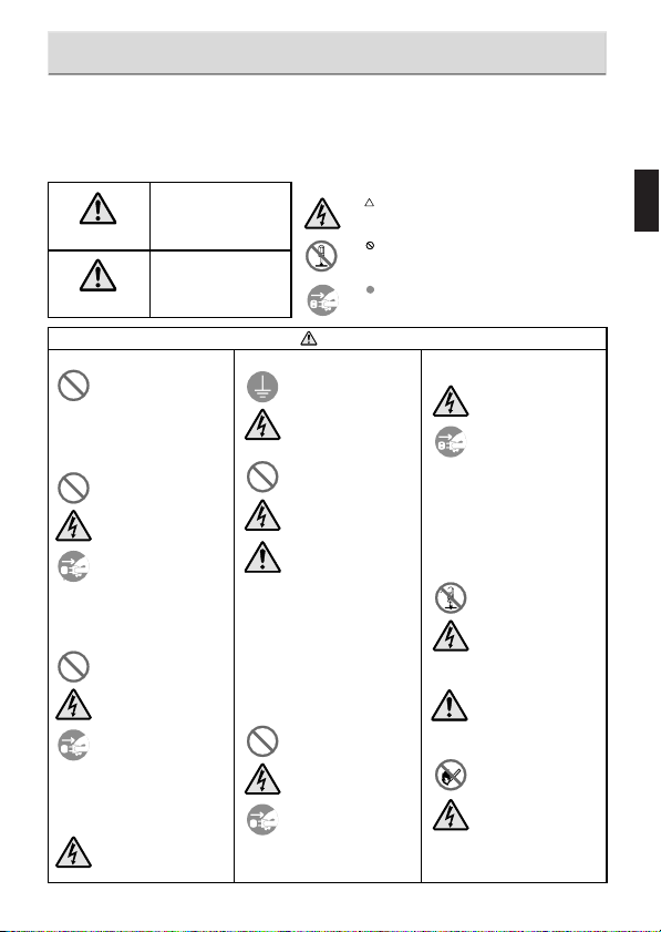
Pictographic Symbols
This instruction manual and the printer labels uses a variety of pictographic symbols to facilitate safe and correct use of the printer and to
prevent injury to others and property damage. The symbols and meanings for them are given below. Be sure to understand these symbols
well before reading the main text.
Ignoring the instructions
marked by this symbol and
erroneously operating the
Warning
Caution
Do not set on an unstable area
Do not place containers full of water
or other liquid on the printer.
Do not put objects inside the printer
Do not use other than
the specified voltage
Version 1 December 10, 2007 Q02073000
©2007 SATO CORPORATION
printer could result in death or
serious injury.
Ignoring the instructions
marked by this symbol and
erroneously operating the
printer could result in injury or
property damage.
• Do not set on an unstable area,
such as a wobbly table or
slanted area or an area subject
to strong vibration. If the printer
falls off or topples over, it could
injure someone.
• Do not place flower vases,
cups, or other containers
holding liquids, such as water
or chemicals, or small metal
objects near the printer. If they
are spilled and get inside the
printer, immediately turn off the
power switch, unplug the power
cord from the outlet, and
contact a store, dealer, or the
Support Center. Using the
printer in this condition could
cause a fire or electric shock.
• Do not insert or drop in metal
or burnable objects inside the
printer’s openings (cable
outlets, etc.). If foreign objects
do get inside the printer,
immediately turn off the power
switch, unplug the power cord
from the outlet, and contact a
store, dealer, or the Support
Center. Using the printer in this
condition could cause a fire or
electric shock.
• Do not use other than the
specified voltage. Doing so
could result in fire or electric
shock.
Example Pictographs
The pictograph means “Caution is required.” A specific
warning symbol is contained inside this pictograph (The symbol
at left is for electric shock).
The pictograph means “Should not be done.” What is
specifically prohibited is contained in or near the pictograph
(The symbol at left means “Disassembly prohibited”).
The pictograph means “Must be done.” What is specifically to
be done is contained in the pictograph (The symbol at left
means “Unplug the power cord from the outlet”).
Always ground the connections
Handling of the power cord
When the printer has been dropped
or broken
Warning
• Always connect the printer’s
ground wire to a ground. Not
grounding the ground wire
could result in electric shock.
• Do not damage, break, or
modify the power cord. Also, do
not place heavy objects on the
power cord, heat it, or pull it
because doing so could
damage the power cord and
cause a fire or electric shock.
• If the power cord becomes
damaged (core is exposed,
wires broken, etc.), contact a
store, dealer, or the Support
Center. Using the power cord in
this condition could cause a fire
or electric shock.
• Do not modify, excessively
bend, twist, or pull the power
cord. Using the power cord in
such a condition could cause a
fire or electric shock.
• If the printer is dropped or
broken, immediately turn off the
power switch, unplug the power
cord from the outlet, and
contact a store, dealer, or the
Support Center. Using the
printer in this condition could
cause a fire or electric shock.
Do not use the printer when
something is abnormal about it
• Continuing to use the printer in
the event something is
abnormal about it, such as
smoke or unusual smells
coming from it, could result in
fire or electric shock.
Immediately turn off the power
switch, unplug the power cord
from the outlet, and contact a
store, dealer, or the Support
Center for repairs. It is
dangerous for the customer to
try to repair it, so absolutely do
not attempt repairs on your
own.
Do not disassemble the printer
• Do not disassemble or modify
the printer. Doing so could
result in fire or electric shock.
Ask the store, dealer, or the
Support Center to conduct
internal inspections,
adjustments, and repairs.
Regarding the cutter
• Do not touch the cutter with
your hands or do not put
something into the cutter. Doing
so could result in an injury.
Using the head cleaning fluid
• Use of flame or heat around the
head cleaning fluid is
prohibited. Absolutely do not
heat it or subject it to flames.
•Keep the fluid out of reach of
children to prevent them from
accidentally drinking it. If the
fluid is drunk, immediately
consult with a physician.
EnglishGermanChineseKorean
3
Page 4

Safety Precautions
Do not place in areas with high humidity
• Do not place the pr inter in
areas with high humidity or
where condensation forms. If
condensation forms,
EnglishGermanChineseKorean
immediately turn off the power
switch and do not use the
printer until it dries. Using the
printer while condensation is on
it could result in electric shock.
Carrying the Printer
•When moving the printer,
always unplug the power cord
from the outlet and check to
make sure all external wires
are disconnected before
moving it. Moving the printer
with the wires still connected
could damage the cords or
connecting wires and result in a
fire or electrical shock.
• Do not carry the printer with
paper loaded in it. The paper
could fall out and cause an
injury.
•When setting the printer on the
floor or a stand, make sure not
to pinch your fingers or hands
under the printer feet.
Power supply
• Do not operate the power
switch or plug in/unplug the
power cord with wet hands.
Doing so could result in electric
shock.
Caution
Power cord
•Keep the power cord away from
hot devices. Getting the power
cord close to hot devices could
cause the cord’s covering to
melt and cause a fire or
electrical shock.
•When unplugging the power
cord from the outlet, be sure to
hold it by the plug. Pulling it by
the cord could expose or break
the core wires and cause a fire
or electric shock.
• The power cord set that comes
with the printer is especially
made for this printer. Do not
use it with any other electrical
devices.
Cover
• Be careful not to pinch your
fingers when opening or closing
the cover. Also be careful the
cover does not slip off and
drop.
Thermal head
• The thermal head is hot after
printing. Be careful not to get
burned when replacing paper
or cleaning immediately after
printing.
•Touching the edge of the
thermal head with bare hands
could result in injury. Be careful
not to become injured when
replacing paper or cleaning.
• The customer should not
replace the thermal head.
Doing so could result in injury,
burns, or electric shock.
Opening and closing the thermal head
•When opening or closing the
thermal head, make sure
nothing other than paper gets
in it. Debris getting in could
cause injury or damage.
Loading paper
•When loading roll paper, be
careful not to get your fingers
pinched between the paper roll
and the supply unit.
• Be careful not to become
injured when opening the fanfolded paper loading slot
window.
When not using the printer
for a long time
•When not using the printer for a
long time, unplug the power
cord from the outlet to maintain
safety.
During maintenance and cleaning
•When maintaining and cleaning
the printer, unplug the power
cord from the outlet to maintain
safety.
(1)
Reproduction in any manner of all or part of this document is prohibited.
(2)
The contents of this document may be changed without prior notice.
(3)
Great care has been taken in the preparation of this document, but if any problems, mistakes, or
omission are found, please contact the store or dealer where you purchased the printer.
Caution
4
Page 5

Accessories Check
The following items are packed together with the main unit in the
box. Be sure to check to make sure nothing is missing. If something
is missing, contact the store or dealer where you purchased the
product.
EnglishGermanChineseKorean
¡
Quick Guide¡Safety manual
¡
Manual (for RoHS) ¡GWP leaflet
¡Test labels and ribbons
¡Dial adjustment screwdriver
* Attached to the printer unit.
The power cord set included with this printer is only for use with this printer.
Do not use it with other electrical products.
Caution
¡Power cord and AC adapter
¡USB cable
¡Ribbon adapter
* The test ribbons and ribbon adapter
come with the thermal transfer model.
5
Page 6
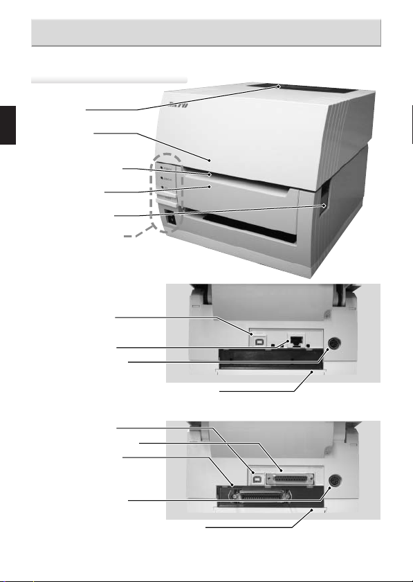
Names of Parts
Printer unit [unit exterior]
¡Window
¡Top cover
EnglishGermanChineseKorean
¡Label discharge
outlet
¡Front cover
¡Opening lever
¡Operation panel
[Back (USB + LAN interface)]
¡USB interface
¡LAN interface
¡DC input power
terminal
(Power connector)
[Back (USB + RS-232C interface)]
¡USB interface
¡RS-232C interface
¡Interface board
The interface can be
changed using an optional
interface board.
¡DC input power
terminal
(Power connector)
6
¡I/F Cover
¡I/F Cover
*Handling of an I/F Cover:
Please close with an I/F Cover after shutting off a
power supply and attaching or removing an I/F
board, in case an I/F Cover is opened.
Page 7

When top cover is opened
[For CT400iDT Series]
¡ Thermal head
¡ Paper holder
¡ Paper sensor
¡ Platen roller
¡ Paper holder
slide lever
[For CT400iTT Series]
¡ Ribbon unit
¡ Paper holder
Names of Parts
EnglishGermanChineseKorean
¡ Paper sensor
¡ Platen roller
¡ Paper holder
slide lever
7
Page 8

Names of Parts
When top cover is opened
[Cutter Type]
¡Cutter top knife
EnglishGermanChineseKorean
¡Paper holder
¡Paper sensor
¡Platen roller
¡Paper holder
slide lever
¡Cutter bottom knife
¡Cutter unit
[Separation Type]
¡Paper holder
¡Paper sensor
¡Platen roller
¡Paper holder
slide lever
¡Backing paper
discharge outlet
(When front cover is open)
(When front cover is open)
¡Separation unit
8
Page 9

Names of Parts
[Operation Panel]
¡ [POWER] lamp
Illuminates (green) when the power switch is on.
¡ [ERROR] lamp
Illuminates or flashes (red) when an error occurs.
¡ [ON LINE] lamp
Illuminates (green) when reception is possible.
¡ [ON LINE] key
This is press to stop/restart and
to terminate data reception.
¡ [FEED] key
This feeds the paper when pressed
while the printer is online.
¡ Power switch
[When the front cover is opened]
¡Separator connector
¡Cutter connector
¡Error display lamp
EnglishGermanChineseKorean
¡Adjustment dial
¡Dip switches
(DSW1)
9
Page 10

Loading the Roll Paper [Continuous, Cutter, Linerless types]
Press down the opening
lever (1) on the right side
1
of the printer to release
the lock and open the top
cover (2).
EnglishGermanChineseKorean
While pressing the paper
holder slide lever (1),
2
adjust the paper holder to
match the paper size (2).
Load the paper into the
paper holder.
3
(2)
(1)
(1)
(2)
After pulling out the
paper, pass the paper
4
through the paper sensor.
10
Paper sensor
Page 11
Loading the Roll Paper [Continuous, Cutter, Linerless types]
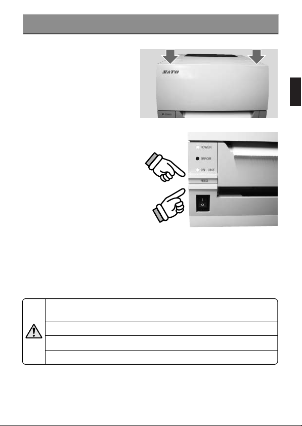
Close the top cover.
5
At this time, press on the
top where shown by the
arrows to close the cover
until you hear the lock
engage.
(1) Press the [FEED] key
to feed the leading edge
6
of the paper.
(2) Finally, press the [ON
LINE] key to bring the
printer online.
After printing, the thermal head and surrounding area are hot. Be careful not
to get burned when replacing paper immediately after printing.
Touching the thermal head with bare hands could result in an injury.
Be careful not to become injured when replacing paper.
Caution
Be careful not to pinch your fingers when closing the top cover.
(2)
(1)
EnglishGermanChineseKorean
11
Page 12

Loading fan-folded paper [Continuous, Cutter types]
Open the window from
the back edge.
1
EnglishGermanChineseKorean
Press down on the
open lever (1) on the
2
right side of the printer
to release the lock and
then open the top
cover (2).
Pass the paper through
the opened window.
3
Window
(2)
(1)
12
Page 13

Loading fan-folded paper [Continuous, Cutter types]
While pressing the paper
holder slide lever (1), adjust
4
the paper holder to match
the paper size (2).
Paper sensor
(1)
After pulling out the paper,
pass it through the paper
sensor.
Close the top cover.
5
At this time, press on the
top where shown by the
arrows to close the cover
until you hear the lock
engage.
(1) Press the [FEED] key to
feed the leading edge of the
6
paper.
(2) Finally, press the [ON
LINE] key to bring the
printer online.
After printing, the thermal head and surrounding area are hot. Be careful not
to get burned when replacing paper immediately after printing.
Touching the thermal head with bare hands could result in an injury.
Caution
Be careful not to become injured when replacing paper.
Be careful not to pinch your fingers when closing the top cover.
(2)
(1)
(2)
EnglishGermanChineseKorean
13
Page 14

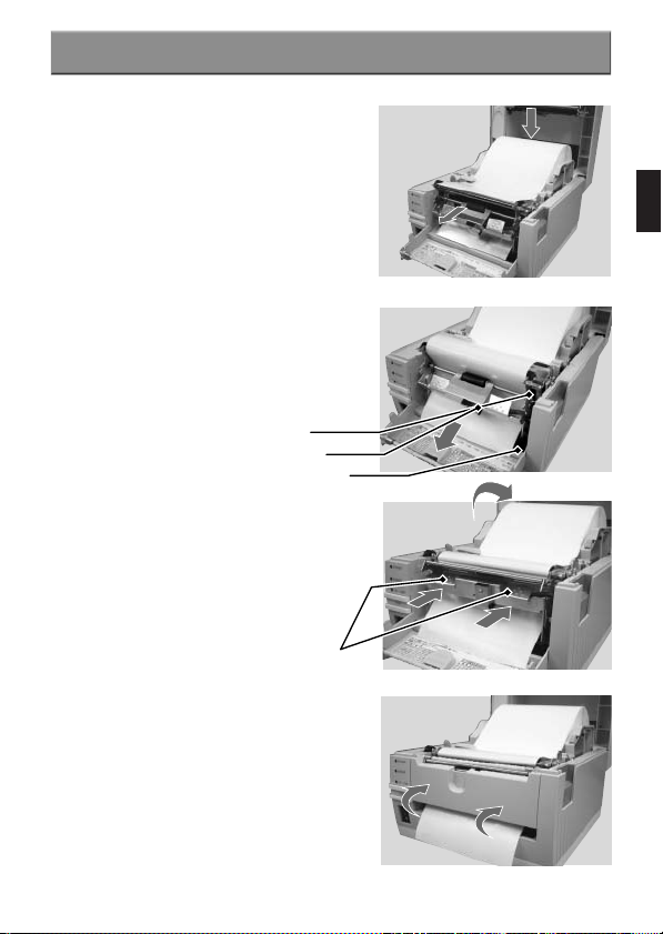
Loading Roll Paper [Separator]
Press down on the open
lever (1) on the right side of
1
the printer to release the lock
and then open the top cover
(2).
EnglishGermanChineseKorean
Open the front cover forward.
2
While pushing on the [PUSH
DOWN] mark on the
3
separator unit, tilt it forward
(1) to open the separator
unit (2).
[PUSH DOWN] mark
When the separator unit is
opened, the separator bar
4
will automatically open in the
direction shown by the
arrow.
(2)
(1)
(1)
(2)
Separator bar
Separator bar
14
Page 15
Loading Roll Paper [Separator]
Peel off labels to expose 15
cm of only the backing paper
5
and then load the paper into
the paper holder.
After pulling out the paper,
pass it through the paper
sensor.
Pass the backing paper
between the separator unit
6
and the platen roller.
Set the backing paper so
that it is below the separator
plate.
Press on the [PUSH DOWN]
mark on the separator unit in
7
the direction shown by the
arrows to close it.
If the backing paper is slack,
turn the labels to wind it up
and remove the slack.
Platen roller
Separator unit
Separator plate
[PUSH DOWN] mark
EnglishGermanChineseKorean
Close the front cover.
8
15
Page 16

Close the top cover.
At this time, press on the top
9
where shown by the arrows
to close the cover until you
hear it lock closed.
EnglishGermanChineseKorean
Loading Roll Paper [Separator]
(1) Press the [FEED] key to
feed the leading edge of the
10
paper.
(2) Finally, press the [ON
LINE] key to bring the printer
online.
After printing, the thermal head and surrounding area are hot. Be careful not
to get burned when replacing paper immediately after printing.
Touching the thermal head with bare hands could result in an injury.
Caution
Be careful not to become injured when replacing paper.
Be careful not to pinch your fingers when closing the top cover.
16
(2)
(1)
Page 17

Printing Position Adjustment
▲
Printing Standard Position
The printing standard position when using labels is the top of the label.
The printing standard position when using fan folded paper is the top of the match mark on the back of
the fan folded paper.
Label
Match mark
Label
Paper feed direction
Standard position (Vertical position 1 dot)
Fan folded paper
Match mark
Fan folded paper
Paper feed direction
Standard position (Vertical position 1 dot)
If the printing standard position is not at the correct position, open the top cover and used the flat head
end of the dial adjustment screwdriver that comes with the printer to adjust the printing standard
position.
Turn left: Moves the printing position forward relative
to the printing direction.
Turn right: Moves the printing position backward relative
to the printing direction.
(Use the dial adjustment screwdriver.)
EnglishGermanChineseKorean
17
Page 18

Cut Position Adjustment
▲
Label Cut
The cut position when using labels is the designated cut position between labels on the blank area (the
area where there is only backing paper).
Labels
EnglishGermanChineseKorean
If the cut position is not the prescribed position, open the top cover and use the Philips head end of the
dial screwdriver attached to the printer unit to adjust the cut position.
Absolutely do not cut on top of the labels because the adhesive will stick to the cutter knife and cause
poor cutting.
Turn left: Stops the label behind the printing direction.
Turn right: Stops the label in front of the printing direction.
(Use the dial adjustment screwdriver.)
▲
Cutting paper with perforated lines
For paper with perforated lines, cutting on or in front of the perforated lines is prohibited.
Cutting in those locations could cause the printer to malfunction.
If cutting on or in front of the perforated line, use the Philips head end of the dial screwdriver
attached to the printer unit to adjust the [OFFSET] so that the cut is behind the perforated line.
The following items are specifications for paper that can be used by this printer, so check them
before using the printer.
(1) Paper thickness (including the backing paper) is 0.08 mm to 0.19 mm. For details contact
the store, dealer, or Support Center.
(2) Cut accuracy is ±1.5 mm.
(3) The cutter unit has a valid cut pitch of 20 to 400 mm. However, the cut size may be
restricted depending on the usage conditions.
(4) The perforated line +1 mm is the cut prohibited zone (Fig. 1).
(5) The folded perforated line +4 mm to +25 mm of fan folded paper is the cut prohibited zone
(Fig.2).
(6) After adjusting the volume, issue about 2 to 5 labels to stabilize the cut position.
Cut prohibited
zone
Backing
paper
Cut position
(Fig. 1) (Fig. 2)
25mm
4mm
Folded perforated
line
Perforated
18
(Fig. 1)
line
(Fig. 2)
Page 19

Loading the Carbon Ribbon
[Loading the Carbon Ribbon]
Press down on the open
lever (1) on the right side of
1
the printer to release the
lock and open the top cover
(2).
(2)
(1)
EnglishGermanChineseKorean
Pull the ribbon unit’s [PULL]
mark to pull the ribbon unit
2
forward.
If the carbon ribbon width is over 92 mm and under 76 mm, use
Steps 3 to 6 to set the carbon ribbon.
For a carbon ribbon with a
width greater than 92 mm,
load the carbon ribbon
directly into the ribbon unit.
For a carbon ribbon with a
width under 76 mm, use a
ribbon adapter to load it into
the ribbon unit.
Ribbon adapter
[PULL] mark
19
Page 20

Loading the Carbon Ribbon
[Loading carbon ribbons with a width greater than 92 mm]
After setting the carbon
ribbon in the right side of
3
the ribbon supply unit (1),
EnglishGermanChineseKorean
press the core guide (2).
(1)
(2)
After setting the ribbon core
in the right side of the
4
ribbon windup unit (1),
press the core guide (2).
Pass the carbon ribbon
from the ribbon supply unit
5
beneath the thermal head
and to the ribbon windup
unit. Affix the carbon ribbon
to the ribbon core using
tape, etc., and wind it up
several times in the
direction shown by the turn
arrow.
Be sure to pass the carbon
ribbon between the thermal
head and the label restraint.
Do not pass it beneath the
label restraint.
20
Ribbon supply unit core guide
(1)
(2)
Ribbon windup unit core guide
Label restraint
Page 21

Loading the Carbon Ribbon
[Loading carbon ribbon with a width under 76 mm]
For carbon ribbon with a width of 76 mm or 59 mm, set the ribbon
adapter hooks at the bottom. From this state, turn the hooks in
3
the direction shown by the arrow to set it at the bottom. If the
carbon ribbon width is 45 mm, use it in that state.
For 76 mm or 59 mm For 45 mm
Set the carbon ribbon in the ribbon adapter.
4
For 76 mm or 59 mm For 45 mm
EnglishGermanChineseKorean
Set the ribbon adapter in which the
carbon ribbon (1) is loaded from the
5
right side of the ribbon supply unit.
Set the ribbon adapter in which the
ribbon core is set from the right
side of the ribbon windup unit (2).
Pass the carbon ribbon from the
ribbon supply unit under the
6
thermal head and to the ribbon
windup unit. Affix the carbon ribbon
to the ribbon core with tape, etc.,
and turn the core several times in
the direction shown by the arrow.
(1)
(2)(2)
Label restraint
21
Page 22

EnglishGermanChineseKorean
Set the ribbon unit in the top
cover and return the cover to its
7
original position.
Closing the top cover after closing the
ribbon unit could prevent the top
cover from closing properly. Always
Caution
put the ribbon unit in the top cover.
Loading the Carbon Ribbon
10
22
For the cutter type, be careful not to
cut your hand on the top cutter knife
when putting the ribbon unit into the
Caution
top cover.
Set the paper in the paper
holder.
8
After pulling out the paper, pass
the paper between the paper
sensors.
Close the top cover.
At this time, press on the top
9
where shown by the arrows to
close the cover until you hear it
lock closed.
(1) Press the [FEED] key to feed
the leading edge of the paper.
(2) Finally, press the [ON LINE]
key to bring the printer online.
The thermal head and surrounding area is hot after printing. When replacing
the carbon ribbon immediately after printing, be careful not to get burned.
Touching the thermal head with bare hands could result in an injury.
Be careful not to get injured when replacing the carbon ribbon.
Caution
Be careful not to pinch your fingers when closing the top cover.
For cutter type printers, be careful not to cut your hands.
Paper sensor
(2)
(1)
Page 23

Connecting to a Computer
[Standard Interface]
¡USB + LAN type
USB interface
LAN interface
(1)When using a USB interface, set DSW 1-8 inside the front cover
to OFF.
When using a LAN interface, set DSW 1-8 inside the front cover
to ON.
(2)To set the USB interface printing support settings or LAN
interface reception mode settings, set DSW 3-2 of the circuit
board on the bottom of the printer.
For details regarding dip switch settings, refer to [Dip Switch
Settings].
/Page 29~31
¡USB + RS-232C type
USB interface
RS-232C interface type
(1)When using a USB interface, set DSW 1-8 inside the front cover
to OFF.
When using an RS-232C interface type, set DSW 1-8 inside the
front cover to ON.
(2)To set the RS-232C interface conditions, set DSW2 of the circuit
board on the bottom of the printer.
(3)To set the USB interface printing support settings, set DSW 3-2 of
the circuit board on the bottom of the printer.
For details regarding dip switch settings, refer to [Dip Switch
Settings].
/Page 29~31
EnglishGermanChineseKorean
23
Page 24

[Extension Interface(Option)]
¡IEEE 1284 interface
Connecting to a Computer
EnglishGermanChineseKorean
IEEE 1284 interface
(1)When using an IEEE 1284 interface, set DSW 3-1 of the circuit
board on the bottom of the printer to ON.
(2)To set the printing support for the IEEE 1284 interface setting, set
DSW3-2 of the circuit board on the bottom of the printer.
For details regarding dip switch settings, refer to [Dip Switch
Settings].
/Page 29~31
¡Wireless LAN2 interface
Wireless LAN2 interface
No
Operation when the dip switch is ON and the printer power is turned on ((1) to (3)).
(1)
Not used
Wireless LAN2 interface board setting information initialization
(2)
(3)
Wireless LAN2 interface board setting information print/Self-diagnostic print
(Prints the setting information, such as IP address, and the wireless LAN2 interface
board diagnostic results.)
(4)
Communication mode
(For wireless LAN operation)
When the LAN cable is connected and the power is turned on, the LAN interface starts up.
When the LAN cable is not connected and the power is turned on, the wireless LAN
interface starts up.
24
Wireless LAN2 interface board Dip Switch Table
OFF: Ad hoc
ON: Infrastructure
ON
(1)(2)(3)(4)
Page 25

Connecting to a Computer
(1)When using the wireless LAN2 interface, set DSW 3-1 of the
circuit board on the bottom of the printer to ON.
(2)When setting the wireless LAN2 interface setting to the reception
mode, set DSW 3-2 of the circuit board on the bottom of the
printer.
For details regarding dip switch settings, refer to [Dip Switch
Settings].
/Page 29~31
¡Bluetooth interface
Bluetooth interface
The Bluetooth interface board is contained
inside the printer and cannot be seen from
outside.
(1)When using the Bluetooth interface, set DSW 3-1 of the circuit
board on the bottom of the printer to ON.
For details regarding dip switch settings, refer to [Dip Switch
Settings].
/Page 29~31
EnglishGermanChineseKorean
25
Page 26

Turning On the Power
Plug the AC adapter/power cord into the printer and turn on the power.
[Power Setting]
When installation is
completed, set the power as
1
shown below.
EnglishGermanChineseKorean
Connect the power cord to
the AC adapter.
2
The plug of the included
power cord is a 3-pronged
plug.
3-prong type outlets use one
of the prongs as a ground.
When the outlet is a 3-prong
type, plug the power cord
directly into it.
Connect the printer → AC
adapter → power cord.
3
When plugging the power
cord into the printer’s power
connector, make sure the
power cord connector is
oriented properly. When
plugging in the power cord
to the printer, use one hand
to hold the printer while
using the other hand to plug
in the cord.
Plug the included AC
adapter into the print and the
4
power cord into the outlet.
When the power outlet is the
2-prong type, use the
included 2-pronged adapter
to plug the power cord into
the power outlet.
Be sure to connect the ground
wire to a ground. Not connecting
the ground wire could result in
Caution Caution
electrical shock.
26
The power cord set included
with this printer is only for use
with this printer. Do not use it
with other electrical products.
Page 27

Turning On the Power
[Turning On the Power]
Turn on the power switch at the front
of the printer.
Switch it to the “ ” symbol.
When the power switch is turned on,
the POWER lamp will illuminate. (The
ONLINE lamp also illuminates.)
Check to make sure this happens.
POWER lamp
ERROR lamp
ONLINE lamp
[ONLINE] key
Power switch
EnglishGermanChineseKorean
Caution
Do not operate the power switch or plug in/unplug the power cord with wet hands.
Doing so could result in electric shock.
[If you think something is wrong...]
When preparation does not go well as it has before, the ONLINE LINE lamp or the
POWER lamp will not illuminate. When preparation is not performed properly, the
ERROR lamp will illuminate or flash. If the ERROR lamp illuminates or flashes, redo
the preparation.
[Turning Off the Power]
After making sure the printer is operating properly, turn off the power.
Do not suddenly turn off the power before making sure the printer is ready to have
the power turned off.
▲
Check the following before turning off the power.
Press the [ONLINE] key and confirm the ONLINE lamp has turned off.
After the ONLINE lamp turns off, turn off the power.
Switch the switch to the “ ” symbol.
[FEED] key
27
Page 28

Printing Operation Confirmation and Error Number Display
[Printer Status Print]
This prints the status of the printer.
The current settings information is printed, so check the settings
printout.
EnglishGermanChineseKorean
Turn on the power while
pressing the [FEED] key.
1
The buzzer will sound, so
then press the following
2
key.
Press the [ON LINE] key
to print a large size.
Press the [FEED] key
to print a small size.
Pressing the [FEED] key during
printing will stop/restart
printing.
The printer setting information is
printed out.
3
Check if the printed information is the
settings values.
28
[ON LINE] key
[FEED] key
(1)(2)(3)(4)(5)(6)(7)(8)
Page 29

Printing Operation Confirmation and Error Number Display
[Dip Switch Settings]
Suitable settings have been made to match the printer’s operating environment,
but in the event the settings are different, please reset the dip switches.
*A detailed explanation of the dip switches is given on the explanation sticker affixed
to the printer.
¡Dip Switch Settings Table DSW1 (Inside the front cover)
USB + LAN type
Mode Change
Continuous
Tear off
Cutter
Separator
Liner less
Par tial cut
Font download
DSW1-1
OFF
ON
OFF
ON
OFF
ON
OFF
USB + RS-232C type
Mode Change
Continuous
Tear off
Cutter
Separator
Liner less
Par tial cut
Font download
DSW1-1
OFF
ON
OFF
ON
OFF
ON
OFF
DSW1-2
OFF
OFF
ON
ON
OFF
ON
ON
DSW1-2
OFF
OFF
ON
ON
OFF
ON
ON
Printing Method
DSW1-3
Direct thermal
OFF
OFF
Thermal transfer
OFF
Head check
OFF
Disable
ON
Enable
ON
VR1 adjustment selection
ON
Offset adjustment
Print density adjustment
DSW1-3
Printing Method
OFF
Direct thermal
OFF
Thermal transfer
OFF
Head check
OFF
Disable
ON
Enable
ON
VR1 adjustment selection
ON
Offset adjustment
Print density adjustment
DSW1-4
OFF
ON
DSW1-5
OFF
ON
DSW1-6
OFF
ON
DSW1-4
OFF
ON
DSW1-5
OFF
ON
DSW1-6
OFF
ON
Dump Mode
Disable
Enable
Interface Change
USB
LAN
Dump Mode
Disable
Enable
Interface Change
USB
RS-232C
DSW1-7
DSW1-8
DSW1-7
DSW1-8
OFF
ON
OFF
ON
OFF
ON
OFF
ON
EnglishGermanChineseKorean
* The head check is a head disconnection guideline and is not a function
warranted for the barcode reader. Check the barcode reader periodically.
29
Page 30

Printing Operation Confirmation and Error Number Display
¡Dip Switch Settings Table DSW2 (RS-232C Interface Settings)
Only for the USB + RS-232C type
To change the dip switch DSW2 settings to make the RS-232C interface
settings, set them as shown below.
EnglishGermanChineseKorean
(1) Turn off the printer power and disconnect the power cord.
(2) Disconnect the connected interface cable.
(3) Remove the paper set in the printer.
(4) Open the cover on the bottom of the printer.
Make the ON/OFF setting for dip switch DSW2 that is on the circuit board and
then switch to the RS-232C interface settings.
(1)(2)(3)(4)(5)(6)(7)(8)
No.
(1)
(2)
(3)
(4)
(5)
(6)
(7)
(8)
30
Function Explanation
Data bit length
Parity bit
Stop bit
Baud rate
Communication protocol
OFF: 8 bit
ON: 7 bit
DSW2-2
OFF
OFF
ON
ON
OFF: 1 bit
ON: 2 bit
DSW2-5
OFF
OFF
ON
ON
DSW2-7
OFF
OFF
ON
ON
DSW2-3
OFF
ON
OFF
ON
DSW2-6
OFF
ON
OFF
ON
DSW2-8
OFF
ON
OFF
ON
Parity bit
None
Even number
Odd number
Not used
Baud rate
9600bps
19200bps
38400bps
57600bps
Protocol
READY/BUSY
XON/XOFF
Status 3 return
Status 4 return
ON
Page 31

Printing Operation Confirmation and Error Number Display
¡
Dip Switch Settings Table DSW3 (Standard/Extension Interface Settings)
To change the dip switch DSW3 settings to make the standard/extension interface
change, set them as shown below.
(1) Turn off the printer power and disconnect the power cord.
(2) Disconnect the connected interface cable.
(3) Remove the paper set in the printer.
(4) Open the cover on the bottom of the printer.
Make the ON/OFF setting for dip switch DSW3 that is on the circuit board and
then switch the standard/extension interface settings.
ON
EnglishGermanChineseKorean
USB + LAN type
No.
(1)
(2)
Function Explanation
Not used
Interface settings
USB + RS-232C type
No.
(1)
(2)
Function Explanation
Standard/extension
Interface change
Interface settings
(1)(2)
Normally OFF
USB interface (DSW1-8 OFF)
DSW3-2
OFF
ON
LAN interface (DSW1-8 ON)
DSW3-2
OFF
ON
OFF :
Standard interface
When DSW1-8 is OFF, USB interface
When DSW1-8 is ON, RS-232C interface
ON :
Extension interface (option)
USB interface (DSW1-8 OFF, DSW3-1 OFF)
DSW3-2
OFF
ON
IEEE 1284 interface (DSW3-1 ON)
DSW3-2
OFF
ON
Wireless LAN2 interface (DSW3-1 ON)
DSW3-2
OFF
ON
Printing port
SATO port
Standard printing port
Reception mode
Periodic response status
ENQ response status
Printing port
SATO port
Standard printing port
Printing port
SATO port
Standard port
Reception mode
Periodic response status
ENQ response status
31
Page 32

¡
Error Messages
Error
Code
0
EnglishGermanChineseKorean
2
FLASH ROM read/write overflow
or write count overflow.
Defective circuit board
Printing Operation Confirmation and Error Number Display
Resolution MethodCause
Contact the store, dealer, or support center.
Contact the store, dealer, or support center.
EEPROM error
3
Thermal head is disconnected
4
or broken.
Top cover is not locked.
5
The paper is dead.
6
Sensor type does not match, or
7
sensor level does not match.
The cutter is not connected, or
the cutter is not operating
8
9
A
b
c
d
r
32
1
normally.*
The ribbon is dead. or ribbon is
2
broken.*
The amount of data sent from
the computer is too high.
There is a problem with the computer’s
communication conditions settings.
Abnormal read/write from the
RFID tag.
Contact the store, dealer, or support center.
Contact the store, dealer, or support center.
Press on both sides of the top of the top cover
until you hear the cover lock in place.
Load new paper
Contact the store, dealer, or support center.
Contact the store, dealer, or support center.
*1 For cutter, linerless, ad partial cutter types.
Correctly load the ribbon.
*2 For thermal transfer printers
Turn the power off and on again. Adjust the
computer’s software data amount to match the
communication conditions. If this does not resolve
the error, check the communication conditions.
Set a new RFID.
Page 33

Basic Specifications
Model name
Printing method
Head density
Printing effective range
Printing speed
Paper
Paper thickness
Shape type
Label size
(Backing paper and
thick paper size)
Sheet capacity
Roll paper
Fan-folded paper
Carbon ribbon
Width
Length
Base material
thickness
Color
Winding direction
Label feed
Dimensions
CT408iDT/CT408iTT
Thermal transfer (DT)/ Thermosensitive (TT)
8-dot/mm (203 dpi)
104 mm wide x 400 mm pitch
Printing is not possible for 1.5 mm from both edges, and printing is not
possible in the I-mark range.
Maximum 6 inchs (Approx. 150 mm/s) Maximum 4 inchs (Approx. 100mm/s)
Note: However, there are times when there are restrictions depending on
Only use paper manufactured and specified by SATO.
0.08 to 0.19 mm
Roll paper, fan-folded paper
Standard
Tear off
Separated
Cutter
linerless
Par tial cut
There may be restrictions depending on the number issued and the paper size and type.
However, there may be restrictions on size depending on the usage conditions.
Max. outside diameter: 110 mm (Approx. 50 m/roll) Using 40 mm paper core
Surface wound (However, linerless is for surface wound only)
Max. folded height: 100 mm (Supplied from outside the printer.)
Refer to “Fan-folded Paper Settings.” / page 12
Only use carbon ribbon manufactured and specified by SATO.
45, 59, 76, 92, 111mm
The carbon ribbon width should be wider than the paper being used.
100 m/roll
4.5
µ
Black (standard)
However, colored ribbon is available.
Surface winding
Continuous, tear off, separated, cutter, linerless, par tial cut
198 W
CT400i Series
CT412iDT/CT412iTT CT424iDT/CT424iTT
12-dot/mm (305 dpi) 24-dot/mm (600 dpi)
Max. 3 inchs (Approx. 75 mm/sec)
the printing layout, paper, and type of carbon ribbon.
Width:
25 to 115 mm (28 to 118 mm)
Pitch:
15 to 397 mm (18 to 400 mm)
Width:
25 to 115 mm (28 to 118 mm)
Pitch:
27 to 397 mm (30 to 400 mm)
Width:
25 to 115 mm (28 to 118 mm)
Pitch:
20 to 120 mm (23 to 123 mm)
Width:
25 to 115 mm (28 to 118 mm)
Pitch:
20 to 397 mm (23 to 400 mm)
Width:
25 to 118 mm
Pitch:
23 to 123 mm
Width:
25 to 115 mm (28 to 118 mm)
Pitch:
20 to 397 mm (23 to 400 mm)
m
×
247 D × 181 H mm (standard)
33
EnglishGermanChineseKorean
Page 34

Basic Specifications
Weight
3.0 kg (standard) Excluding AC adapter,battery
Power supply
AC adapter
Input voltage
Output voltage
Power consumption
EnglishGermanChineseKorean
Environmental
conditions
AC 100 to 240V (1.5A) 50/60 Hz
DC 25V (2.0A)
Print ratio 30% 180VA 120W
Maximum 280VA 180W
During standby 30VA 15W
Operation ambient temperature: 5 to 35°C
Storage ambient temperature : -5 to 60
Excluding paper and carbon ribbon
Humidity: 30 to 80% (However, no dew formation)
Humidity: 30 to 90% (However, no dew formation)
°
C
External interface
Standard interface
USB + LAN type
USB (Full Speed)
LAN (10BASE-T/100BASE-TX automatic switching)
USB + RS-232C type
USB (Full Speed)
RS-232C
Extension interface
Operation panel
Keys
Switches
lamp
Adjustment dials
USB + RS-232C type
Parallel (IEEE 1284)
Wireless LAN2 (LAN: 10BASE-T/100BASE-TX automatic switching,
Wireless LAN: IEEE 802.11 b/g)
Bluetooth (Bluetooth Specification Ver. 1.1 Class 2)
LINE, FEED
POWER switch, DIP switch
POWER, ONLINE, ERROR, 7SEG lamp
Paper sensor adjustment, printing position adjustment, printing density
adjustment, tear off/separated/cutter stop position adjustment.
However, printing density adjustment and tear off/separated/cutter stop
position adjustment are switched using DSW1-6.
Sensor Paper sensor reflection type, transparent type
Printing format Transfer from host (computer)(with format registration function)
34
Page 35

Basic Specifications
Contained fonts
Standard
Barcode
2D Barcode
Composite Symbol
Magnification
Rotation
Characters
Barcode
Barcode ratio 1:2, 1:3, 2:5, Free specification
Self-diagnostic function
Noise standard
Emitted noise FCC, CE, CCC, MIC (If differs in each destination)
Options Separation unit, cutter unit, Linerless unit, RFID unit, interface board
XU 5 × 9 dots (alphanumeric, symbol)
XS 17 × 17 dots (alphanumeric, symbol)
XM 24 × 24 dots (alphanumeric, symbol)
XB 48 × 48 dots (alphanumeric, symbol)
XL 48 × 48 dots (alphanumeric, symbol)
Outline font (alphanumeric, symbol)
OCR-A 15×22 dots
(alphanumeric, symbol)
×
OCR-B 20
(alphanumeric, symbol)
24 dots
UPC-A/UPC-E, JAN/EAN, CODE39, CODE93, CODE128,
GS1-128(UCC/EAN-128), CODABAR(NW-7), ITF, Industrial 2of5,
Matrix 2of5, BOOKLAND, MSI, POSTNET, GS1 DataBar(RSS)
QR Code, Micro QR, PDF417, Micro PDF, MAXI Code,
GS1 DataMatrix(ECC200)
Composite Symbol(JAN/EAN, UPC-A/UPC-E,
GS1-128, GS1 DataBar(RSS))
Ve rtical
×
1 to ×12, horizontal ×1 to ×12 (characters)
1 to 12L (barcode)
0
°
, 90°, 180°, 270
Parallel 1, Serial 1, Parallel 2, Serial 2
Head check, head/cover open, paper end, ribbon end, test print
(Parallel (IEEE 1284), Wireless LAN2 (LAN: 10BASE-T/100BASE-TX
automatic switching, Wireless LAN: IEEE 802.11 b/g), Bluetooth)
OCR-A 22
(alphanumeric, symbol)
OCR-B 30
(alphanumeric, symbol)
°
×
33 dots
×
36 dots
OCR-A 44
×
(alphanumeric, symbol)
OCR-B 60
(alphanumeric, symbol)
66 dots
×
72 dots
EnglishGermanChineseKorean
Notice regarding the registered trademarks and trademarks of other companies
QR Code is a registered trademark of DENSO WAVE INCORPORATED.
35
 Loading...