


Sanmotion F5
Table of contents
 Loading...
5-PHASE STEPPING SYSTEMS
Ver.3
1
Load:JL:0.6×10
-4
kg・m
2
(2050.3×10
-4
lb・in
2
)
F series driver
2 4 6 8 10
Rise time
(
ms
)
0
200
400
600
800
1000
Reduced 10%
Current model
Number of rotations(min
-1
)
5-phase STEPPING SYSTEMS
F series DRIVER
F series MOTOR
M series MOTOR
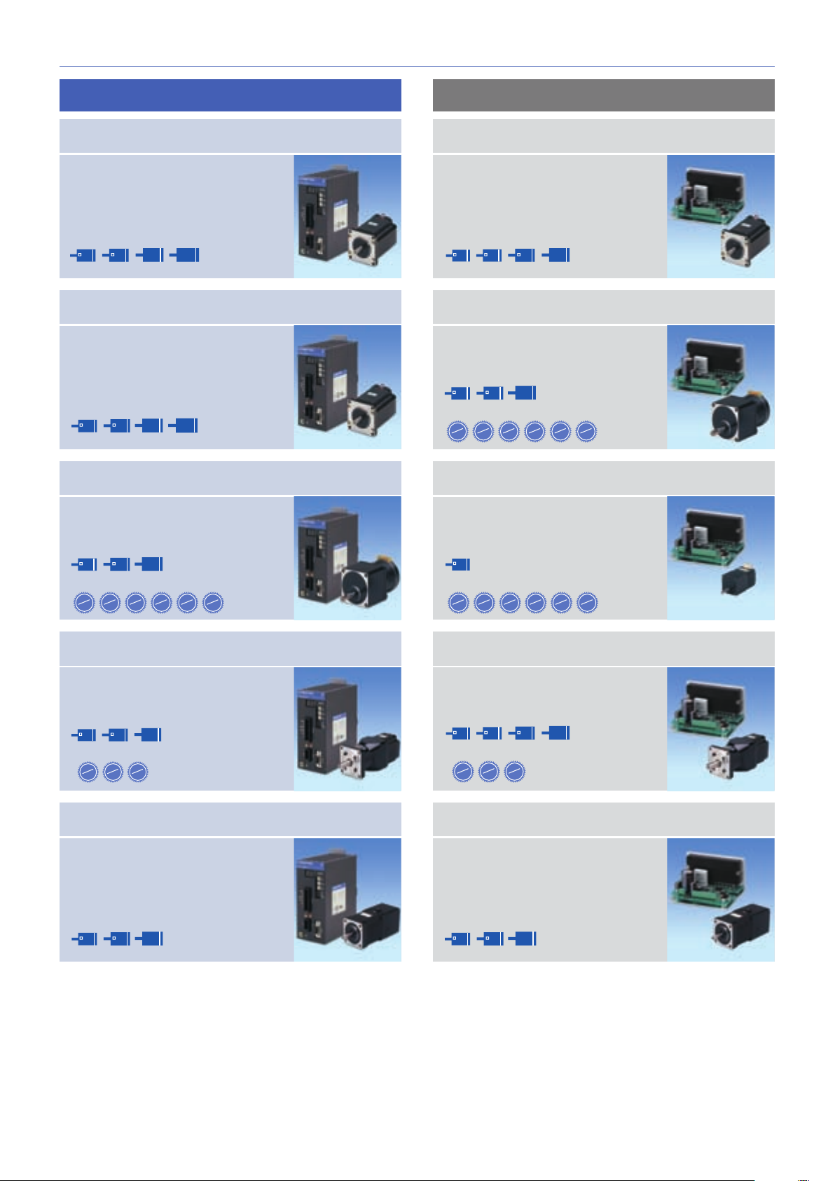
Extensive lineup
F series driver features
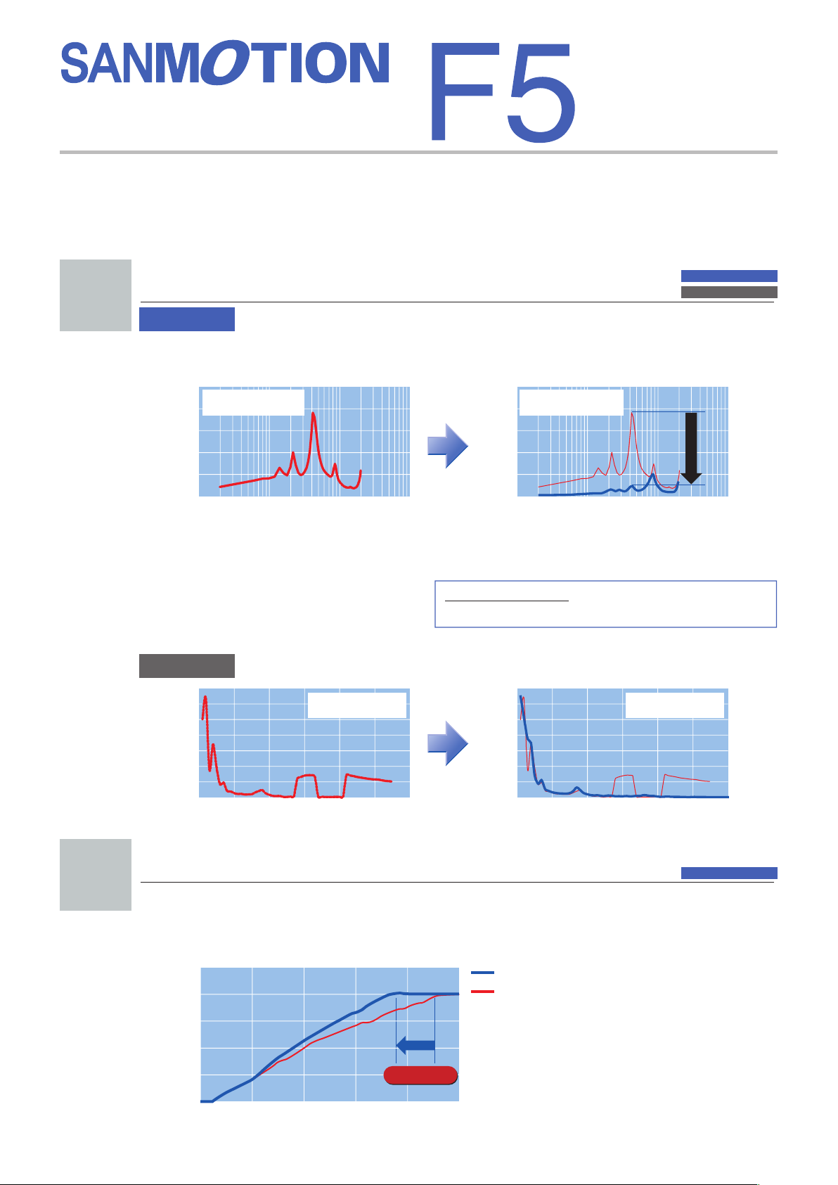
Lower vibration
1
Shoter cycle time
■
Improved response
(
up to 10% compared to current models
)
shortens the machine cycle
time for repetitive operations.
2
Rotation-vibration characteristics
(
Full-step
)
0.01
0.1
1 10
Number of rotations(S
1
)
Motor : 103F7851-7041
Power source voltage
: 100V AC
Winding current : 0.75A/phase
0
0.2
0.4
0.6
0.8
1
(Vrms) (Vrms)
Rotation-vibration characteristicsx
(
1 / 250
)
Current model
New model
0.01 0.1 1 10
Number of rotations(S
1
)
Motor : 103F7851-7041
Power source voltage
: 100V AC
Winding current : 0.75A/phase
0
0.2
0.4
0.6
0.8
1
0
50
100
150
200
250
300
350
0123 45 6
Number of rotations
(
S
1
)
Motor : 103F7852-8241
Power source voltage:DC24V
Excitation method:Half-step
0
50
100
150
200
250
300
350
0123 45 6
Number of rotations
(
S
1
)
Speed variation(%)
Speed variation(%)
TG ripple voltage
TG ripple voltage
Motor : 103F7852-8241
Power source voltage:DC24V
Excitation method:Half-step
0.72
1 to 250 divisions
=
0.72 to 0.00288degrees/pulse
AC input
DC input
AC input
DC input
■
Automicro function
Vibration suppression is executed internally and independently from the controller.
AC input
■
Automicro function and microstepping system enables further reduction of vibration
compared to current models.
■
Microstepping system
The basic step angle is divided by a maximum of
1 / 250 using 16 selectable resolution levels to enable
smooth and vibration-free operation.
2
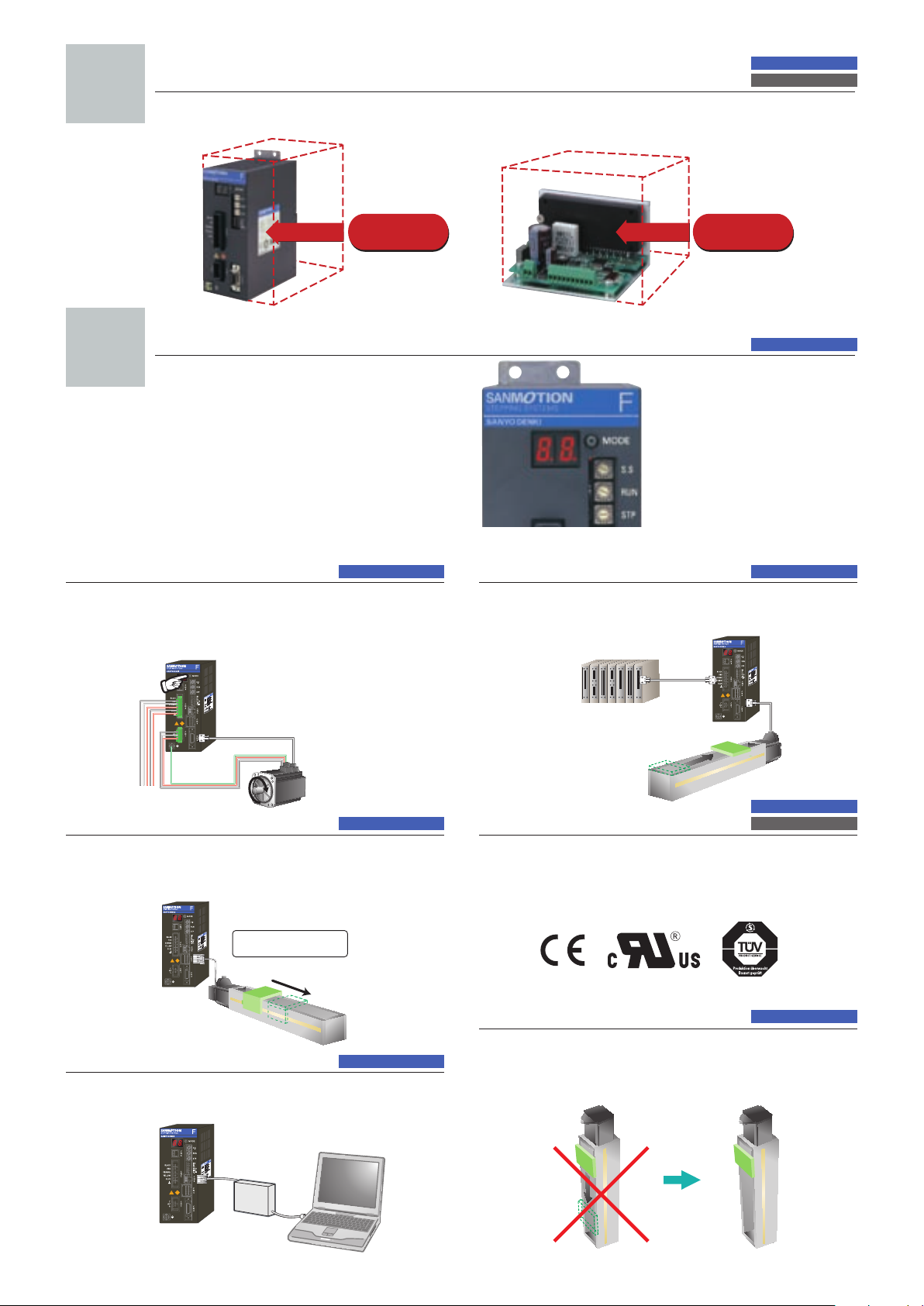
Control panel space is reduced
■
Volume is reduced by up to 50% for AC input types and 45% for DC input types compared
to current models.
3
Easy maintenance
■
2-digit 7-segment LED displays
operating status and alarm for
easy troubleshooting and
faster system recovery.
4
50% reduction
for 200V types
Test run function
(
JOG
)
With built-in positioning func tion
On-board JOG operation function is available for testing motor
and amplifier connection without the need to connect to host
device.
Encoder I/F Control
With built-in positioning func tion
Motor stall detection is possible by connecting a motor encoder. 500P/
R
(
1000/2000 multiplier function
)
line driver method.
PC-based setup monitor
With built-in positioning func tion
Parameter and program settings can be made from the bundled
setup software.
Capable of JOG operation
without connecting to host
device
PLC
F motor
Designate
program
number”1”
Load
Highly precise positioning
is possible
Parameter
(
position, speed
)
Program settings
AC input
AC input
DC input
AC inputAC input
AC input
AC input
AC input
DC input
45% reduction
for 24V types
AC input
F motor
Tare weight
General-purpose I/O input
for positioning
With built-in positioning func tion
System positioning is easily executed by using general-purpose
I/O from an upper-level controller
(
PLC
)
to designate preset
program numbers.
Compliance with
international standards
Th e standard spe cifi cation S ANMOTION F series s tep ping
driver complies with UL and EN safety standards . Step ping
motors complying with UL an
d EN standards are available upon
r
equest. EMC filters are also available to comply with the EMC
directive.
Brake control
Automatic brake activation timing control is available when
using electromagnetic brake motors.
• Internal power source for brake
(
FP type
)
3
5-phase STEPPING SYSTEMS
F series DRIVER
F series MOTOR
M series MOTOR
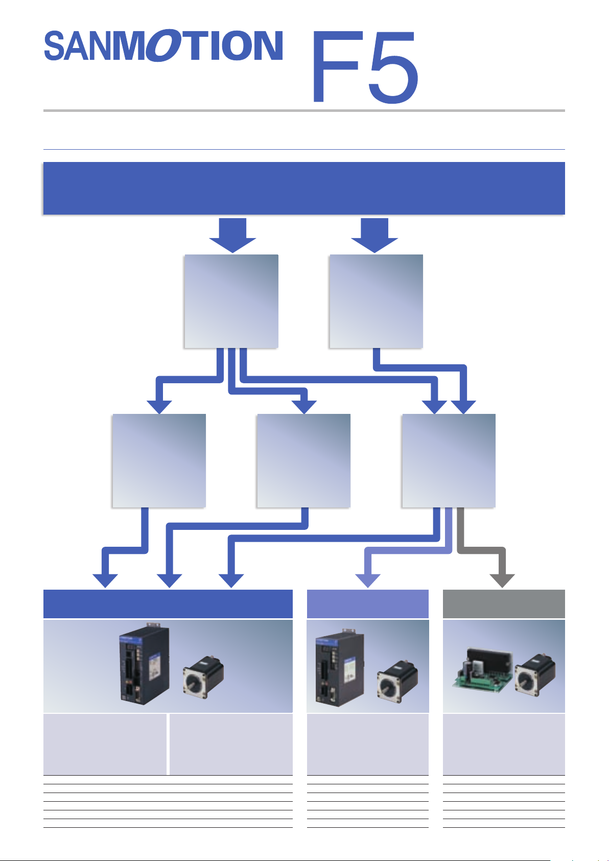
How do you want to control the equipment ?
The F series offers the choice of 3 different control methods
Control method
Point command
control using
PLC I/O
Network control
using serial
communication
(
RS-485
)
Control using a
pulse generator
AC power
source
DC power
source
AC input
with built-in positioning function
Startup via I/O :
Initiate program c ont aining
speed, acceleration/deceleration,
and travel distance commands
stored in the driver via the I/O.
Startup via serial
communication:
Control by sending data for
speed, acceleration/deceleration,
and travel distance commands
via serial communication.
System confi guration diagram P7
Set part number nomenclature P9
Motor specifi cations P47 to 58
General specifi cations P 25
・
26, 60
Motor dimension drawing P61 to 67
Driver dimension drawing P68
AC input
standard type
Motion is generated by pulse
input commands from an
upper-level controller.
System confi guration diagram P5
Set part number nomenclature P9
Motor specifi cations P47 to 58
General specifi cations P23
・
24, 60
Motor dimension drawing
P61 to 67
Driver dimension drawing P68
DC input
Motion is generated by pulse
input commands from an
upper-level controller.
System confi guration diagram P29
Set part number nomenclature P31
Motor specifi cations P47 to 58
General specifi cations P43
・
44, 60
Motor dimension drawing
P61 to 67
Driver dimension drawing P68
4
Motor flange size
Reduction gear ratios
30
1
50
1
100
1
42
60
ø
86
(
□
1.65inch)(
□
2.35inch)(
ø
3.39inch)
Harmonic gear model
This set utilizes a harmonic gear.
42
60
ø
86
Motor flange size
(
□
2.35inch)(
□
1.65inch) (
ø
3.39inch)
Electromagnetic brake model
This set utilizes a non-excitation
electromagnetic brake to maintain
position in vertical load applications
and hold load even during power off.
42
60
ø
86
Motor flange size
3.6
1
7.2
1
10
1
20
1
30
1
36
1
Reduction gear ratios
(
□
1.65inch)(
□
2.35inch)(
ø
3.39inch)
Low-backlash gear model
This set includes a low backlash gear that
uses tapered hobbed gears to engage the
final stage of the speed reduction mechanism.
42
60
ø
86
ø
106
Motor flange size
(
□
1.65inch)(
□
2.35inch)(
ø
3.36inch)(
ø
4.17inch)
CE / UL model
The UL/CE set includes a F Series
driver and a M Series motor.
Set model
DC inputAC input
Motor flange size
42
60
ø
86
ø
106
(
□
1.65inch)(
□
2.35inch)(
ø
3.39inch)(
ø
4.17inch)
Standard model
The standard set includes a F series
driver and a F series motor.
P.19
P.21
28
Motor flange size
3.6
1
7.2
1
10
1
20
1
30
1
50
1
Reduction gear ratios
(
□
1.10inch)
Spur gear model
This set utilizes a spur gear in the
speed reduction mechanism.
28 42
60
ø
86
Motor flange size
Reduction gear ratios
30
1
50
1
100
1
(
□
1.65inch)(
□
1.10inch) (
□
2.35inch)(
ø
3.39inch)
Harmonic gear model
This set utilizes a harmonic gear.
42
60
ø
86
Motor flange size
(
□
2.35inch)(
□
1.65inch) (
ø
3.39inch)
Electromagnetic brake model
This set utilizes a non-excitation
electromagnetic brake to maintain
position in vertical load applications
and hold load even during power off.
P.35
42
60
ø
86
Motor flange size
3.6
1
7.2
1
10
1
20
1
30
1
36
1
Reduction gear ratios
(
□
1.65inch)(
□
2.35inch)(
ø
3.39inch)
Low-backlash gear model
This set includes a low backlash gear that
uses tapered hobbed gears to engage the
final stage of the speed reduction mechanism.
P.33
Standard model
The standard set includes a F series
driver and a F series motor.
P.38
P.39
P.41
28 42
60
ø
86
ø
106
Motor flange size
(
□
1.65inch)(
□
1.10inch) (
□
2.35inch)(
ø
3.39inch
)(
ø
4.17inch)
P.12
P.14
P.16
5
5-phase STEPPING SYSTEMS
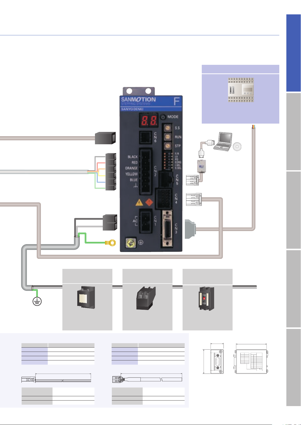
System configuration
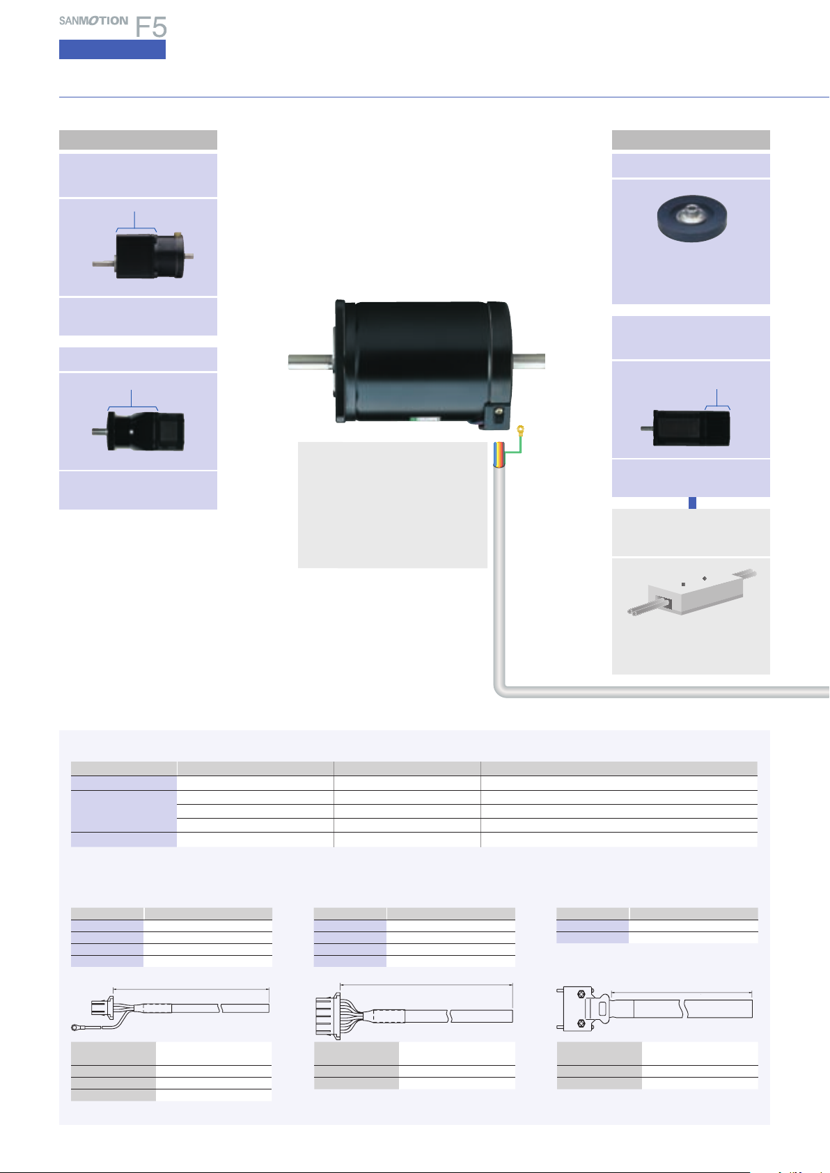
AC input
Standard type
Harmonic gear model
Motor flange size
□
42mm
(
□
1.65inch
)
/
□
60mm
(
□
2.35inch
)
/
φ
86mm
(
φ
3.39inch
)
Harmonic gear
Low-backlash gear
model
Low backlash gear
Motor flange size
□
42mm
(
□
1.65inch
)
/
□
60mm
(
□
2.35inch
)
/
φ
86mm
(
φ
3.39inch
)
Brake power source
(
DC24V
)
Electromagnetic
brake model
Damper
End-cap side
Motor flange size
□
42mm
(
□
1.65inch
)
/
□
60mm
(
□
2.35inch
)
/
φ
86mm
(
φ
3.39inch
)
Electromagnetic brake
Magnetic dampers can be
selected according to the
required inertia.
Required for brake-equipped
stepping motor models.
●
A
AC power cable
■
Optional cables
●
B
Motor cable
L
( feet)
+50 mm
− 0 mm
+.16
− 0
L
( feet)
+50 mm
− 0 mm
+.16
− 0
L
(
feet
)
+50 mm
− 0 mm
+.16
− 0
●
C
I/O signal cable
Standard model : F series motor
□
42mm
(
□
1.65inch
)
/
□
60mm
(
□
2.35inch
)
/
φ
86mm
(
φ
3.39inch
)
/
φ
106mm
(
φ
4.17inch
)
CE / UL model : M series motor
□
42mm
(
□
1.65inch
)
/
□
60mm
(
□
2.35inch
)
/
φ
86mm
φ
3.39inch
)
/
φ
106mm
(
φ
4.17inch
)
●
Motors are available in standard or vacuum
types.
●
Motor cable
(
optional
)
B
L : m
(
feet
)
Part number
10
(
32.81
)
PM-C03P1000-05
5
(
16.40
)
PM-C03P0 500-05
3
(
9.84
)
PM-C03P0300-05
1
(
3.28
)
PM-C03P0100-0 5
Leadwire
600V vinyl cab tire cable
3-c ore AWG16
(
1.25mm
2
)
Housing 1-178128-2
(
AMP
)
Contact 1-175218-5
(
AMP
)
Round-type crimp contact
1.25M4
(
J.S.T. Mfg Co.
)
Connec tor typ e Housing Contac t Applicable moto r flange size
●
AC power connector
1-178128-2
(
AMP
)
1-175218-5
(
AMP
)
─
●
Motor connec tor
1-178128-6
(
AMP
)
1-175216-5
(
AMP
)
□
42mm
(
□
1.65inch
)
1-178128-6
(
AMP
)
1-175217-5
(
AMP
)
□
60mm
(
□
2.35inch
)
,
φ
86mm
(
φ
3.39inch
)
1-178128-6
(
AMP
)
1-175218-5
(
AMP
)
φ
106mm
(
φ
4.17inch
)
●
I/O signal connector
10314-52A0-008
(
3M
)
10114-3000PE
(
3M
)
─
■
Bundled connectors
(
set models only
)
1
2
3
●
Cables 10m
(
32.81 feet
)
or longer are available
upon request.
L : m
(
feet
)
Part number
10
(
32.81
)
PM-C06M1000-11
5
(
16.40
)
PM-C06M0500 -11
3
(
9.84
)
PM-C06M0300 -11
1
(
3.28
)
PM-C06M0100-11
L : m
(
feet
)
Part number
2
(
6.56
)
PM-C14S0200-03
1
(
3.28
)
PM-C14S0100-03
●
Cables 10m
(
32.81 feet
)
or longer are available
upon request.
Leadwire
600V vinyl cab tire cable
6-core AWG16
(
0.75mm
2
)
Housing 1-178128-6
(
AMP
)
Contact 1-175218-5
(
AMP
)
Leadwire
7-pair PVC shielded cable
AWG28
(
0.08mm
2
)
Shell 10314 -52 A0- 008
(
3M
)
Plug 10114-3000PE
(
3M
)
Flange side
6
AC inputInput / Output signal standardDC inputStepping motorDimensions
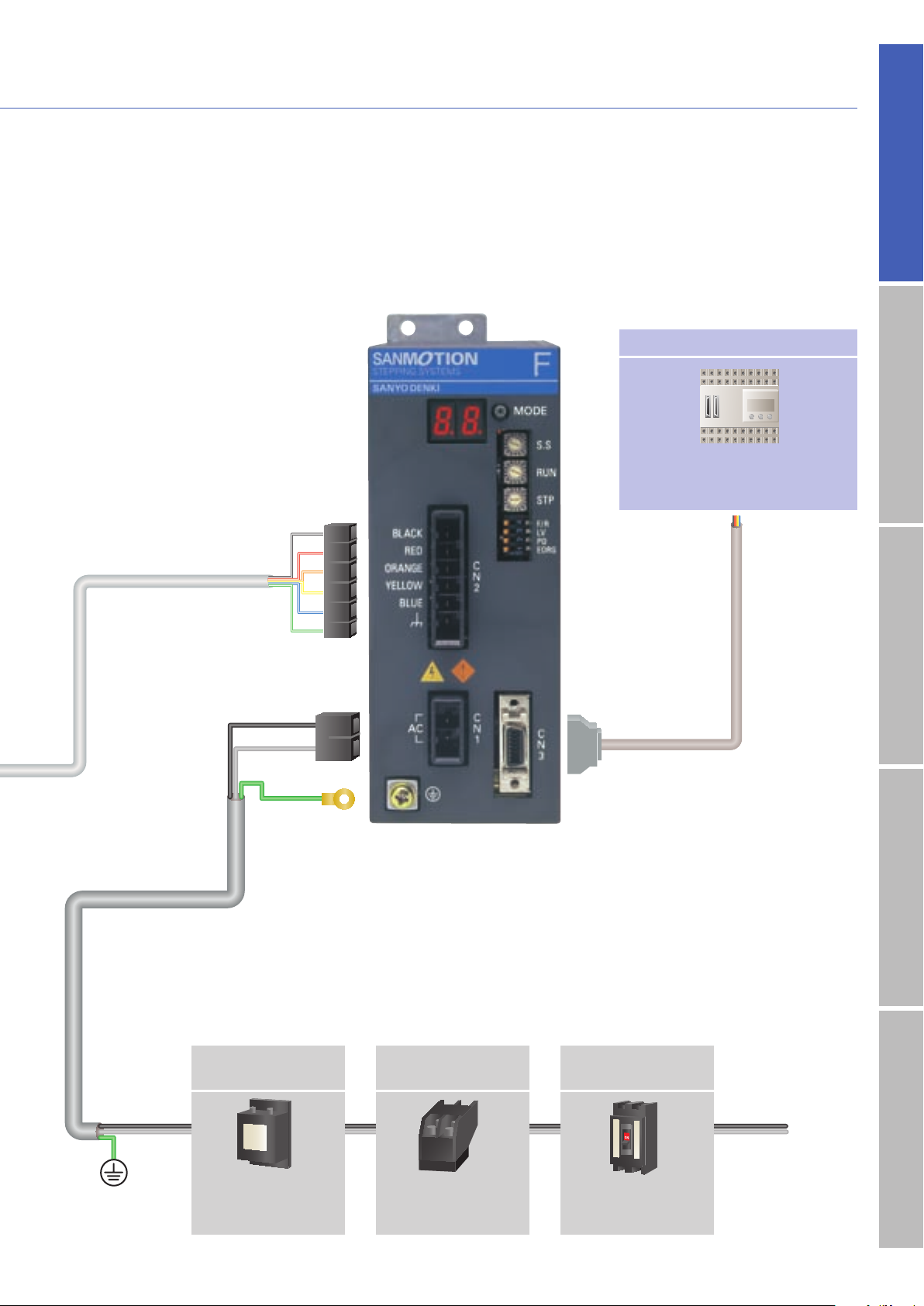
Host Devices
PLC and controllers are available as
the host device.
Single
phase
AC100V
to
AC230V
(
t
)
(
r
)
●
I/O signal connector
(
bundled
)
●
I/O signal cable
(
optional
)
C
3
●
Motor connector
(
bundled
)
2
●
AC power connector
(
bundled
)
1
●
AC power cable
(
optional
)
A
Molded case
circuit breaker
Noise filter
Electromagnetic
contactor
Switches driver power
on/off. Use together
with a surge protector.
Filters out incoming
noise from power line
Protects the power line.
Cuts off circuit in the
event of overcurrent.
PLC
7
5-phase STEPPING SYSTEMS
System configuration
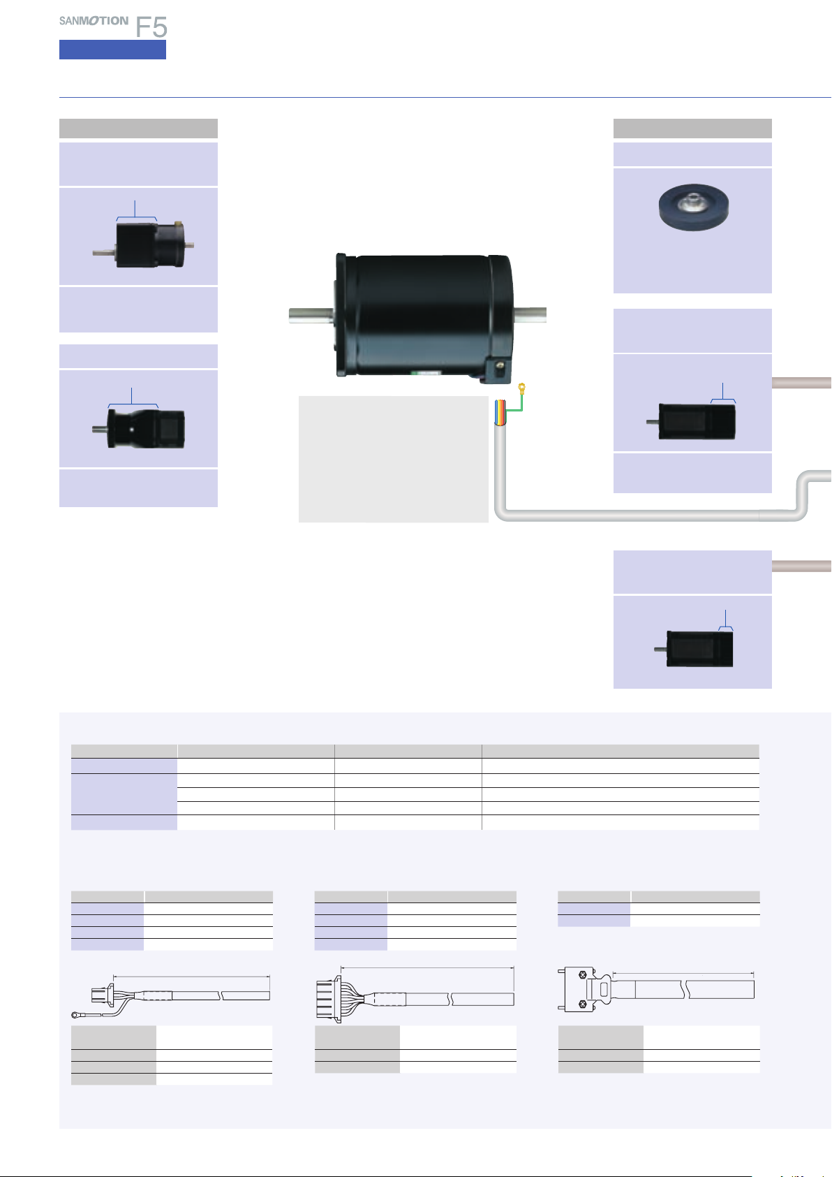
AC input
Damper
Electromagnetic
brake model
End - cap side
With built-in positioning function
Motor flange size
□
42mm
(
□
1.65inch
)
/
□
60mm
(
□
2.35inch
)
/
φ
86mm
(
φ
3.39inch
)
Harmonic gear model
Motor flange size
□
42mm
(
□
1.65inch
)
/
□
60mm
(
□
2.35inch
)
/
φ
86mm
(
φ
3.39inch
)
Harmonic gear
Low-backlash gear
model
Low backlash gear
Motor flange size
□
42mm
(
□
1.65inch
)
/
□
60mm
(
□
2.35inch
)
/
φ
86mm
(
φ
3.39inch
)
Electromagnetic brake
●
A
AC power cable
■
Optional cables
●
B
Motor cable
●
C
I/O signal cable
Flange side
Magnetic dampers can be
selected according to the
required inertia.
Encoder equipped
model
Optional
Encoder
L
( feet)
+50 mm
− 0 mm
+.16
− 0
L
( feet)
+50 mm
− 0 mm
+.16
− 0
L
(
feet
)
+50 mm
− 0 mm
+.16
− 0
Standard model : F series motor
□
42mm
(
□
1.65inch
)
/
□
60mm
(
□
2.35inch
)
/
φ
86mm
(
φ
3.39inch
)
/
φ
106mm
(
φ
4.17inch
)
CE / UL model : M series motor
□
42mm
(
□
1.65inch
)
/
□
60mm
(
□
2.35inch
)
/
φ
86mm
(
φ
3.39inch
)
/
φ
106mm
(
φ
4.17inch
)
●
Motors are available in standard or vacuum
types.
●
Option cable for motor
B
L : m
(
feet
)
Part number
10
(
32.81
)
PM-C03P1000-05
5
(
16.40
)
PM-C03P0 500-05
3
(
9.84
)
PM-C03P0300-05
1
(
3.28
)
PM-C03P0100-0 5
L : m
(
feet
)
Part number
10
(
32.81
)
PM-C06M1000-11
5
(
16.40
)
PM-C06M0500 -11
3
(
9.84
)
PM-C06M0300 -11
1
(
3.28
)
PM-C06M0100-11
L : m
(
feet
)
Part number
2
(
6.56
)
PM-C 20S0200- 01
1
(
3.28
)
PM-C 20S0100-01
Leadwire
600V vinyl cab tire cable
3-c ore AWG16
(
1.25mm
2
)
Housing 1-178128-2
(
AMP
)
Contact 1-175218-5
(
AMP
)
Round-type crimp tool
1.25M4
(
J.S.T.
)
●
Cables 10 m
(
32.81 feet
)
or longer are available
upon request.
Leadwire
600V vinyl cab tire cable
6-core AWG16
(
0.75mm
2
)
Housing 1-178128-6
(
AMP
)
Contact 1-175218-5
(
AMP
)
Leadwire
10-pair PVC shielded cable
AWG28
(
0.08mm
2
)
Shell 10320-52A0-0 08
(
3M
)
Plug 10120-3000PE
(
3M
)
Connec tor typ e Housing Contac t Applicable moto r flange size
●
AC power connector
1-178128-2
(
AMP
)
1-175218-5
(
AMP
)
─
●
Motor connec tor
1-178128-6
(
AMP
)
1-175216-5
(
AMP
)
□
42mm
(
□
1.65inch
)
1-178128-6
(
AMP
)
1-175217-5
(
AMP
)
□
60mm
(
□
2.35inch
)
,
φ
86mm
(
φ
3.39inch
)
1-178128-6
(
AMP
)
1-175218-5
(
AMP
)
φ
106mm
(
φ
4.17inch
)
●
I/O signal connector
10314-52A0-008
(
3M
)
10114-3000PE
(
3M
)
─
■
Bundled connectors
(
set models only
)
1
2
3
●
Cables 10 m
(
32.81 feet
)
or longer are available
upon request.
8
AC inputInput / Output signal standardDC inputStepping motorDimensions
RS485
RS232C
Molded case
circuit breaker
Noise filter
Electromagnetic
contactor
Switches driver power
on/off. Use together
with a surge protector.
Filters out incoming
noise from power line.
Protects the power line.
Cuts off circuit in the
event of overcurrent.
Single
phase
AC100V
to
AC230V
(
t
)
(
r
)
●
Encoder cable
E
●
Motor connector
(
bundled
)
2
●
AC power
connector
(
bundled
)
1
●
AC power cable
(
optional
)
A
L
( feet)
+50 mm
− 0 mm
+.16
− 0
●
D
Brake cable
L
(
feet
)
+50 mm
− 0 mm
+.16
− 0
●
E
Cable for encoder use
●
I/O Signal
Connector
(
bundled
)
3
●
I/O signal cable
(
optional
)
C
●
Brake connector
2
●
Brake cable
D
63.5(2.52)
27(1.06)
50(1.77)
B3
C N 2
C N 1
57600
Term
2
F.Dup
Func Parity
C N 3
bps
UseNone
No.
1
toGND
Echo
to+5V
91
19200
9600
80
38400
A2
3
6,7
4,5
307200
F7
None
D5
128000
115200
C4
153600
E6
8
DSWRSWRX TX
●
F
Part number for RS232C-RS485 converter :
232485CFP01-01
●
G
RS232 cable is supplied by user.
●
H
Part number for FP communications cable :
PM-C08S0100-05
●
J
Part number for bundled software :
SFPA1W-01
(
please download from website
)
●
F
Converter [unit : mm
(
inch
)
]
●
Cable
H
●
Converter
F
●
G
●
Software
J
L : m
(
feet
)
Part number
10
(
32.81
)
PM-C03B1000-01
5
(
16.40
)
PM-C03B0500-01
3
(
9.84
)
PM-C03B0300-01
1
(
3.28
)
PM-C03B0100-01
Leadwire
PVC cable
AWG22
(
0.3mm
2
)
Housing 1-1318120-3
(
AMP
)
Contact 1318107-1
(
AMP
)
Leadwire
4-pair PVC shielded cable
AWG22
(
0.3mm
2
)
Housing 1-1318118-6
(
AMP
)
Plug 1318107-1
(
AMP
)
L : m
(
feet
)
Part number
10
(
32.81
)
PM-C12S1000-01
5
(
16.40
)
PM-C12S0500-01
3
(
9.84
)
PM-C12S0300-01
1
(
3.28
)
PM-C12S0100-01
Host Devices
PLC and controllers are available as
the host device.
PLC
9
5-phase STEPPING SYSTEMS
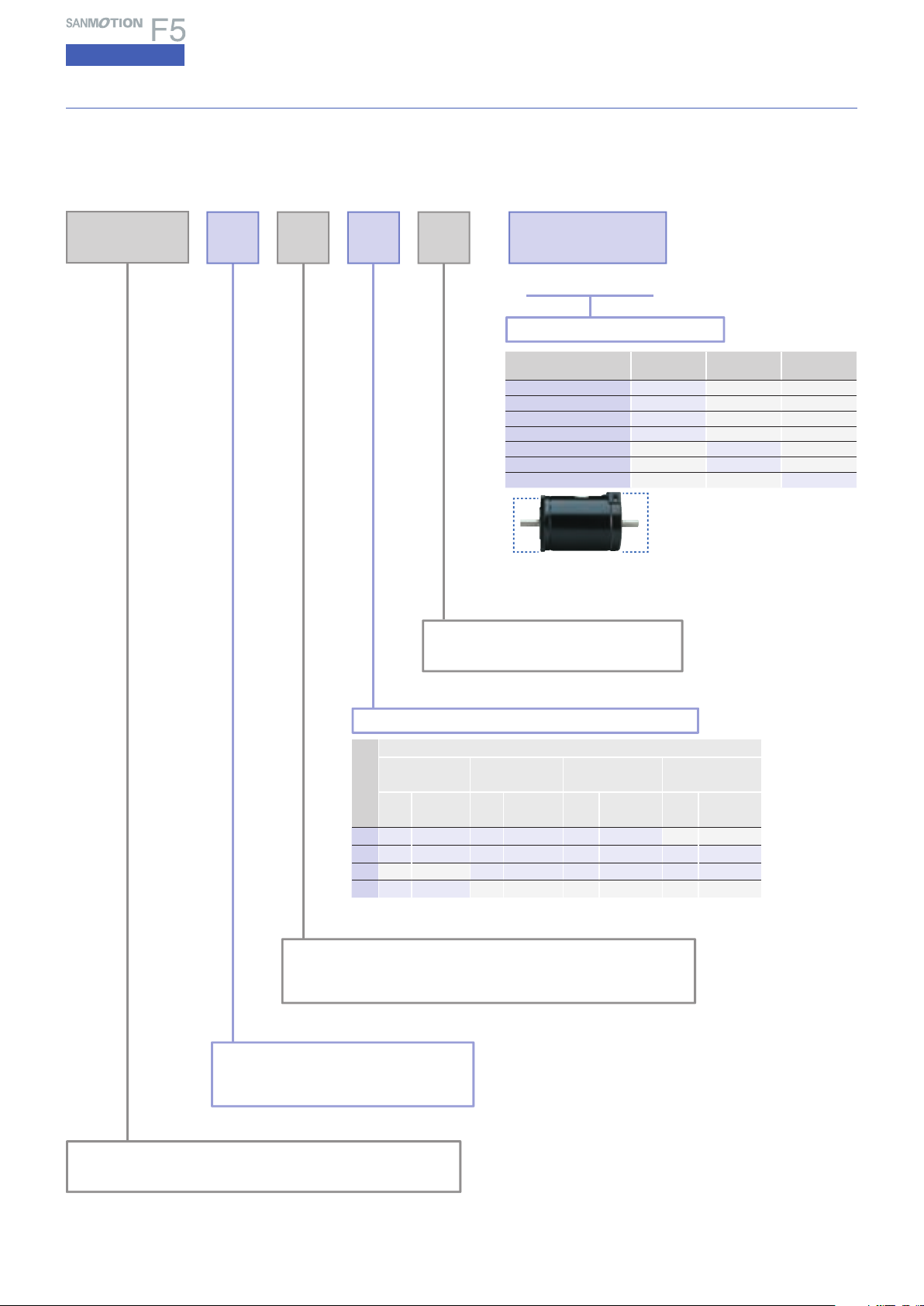
AC input
Part number convention
The following part number specifies a system with an F series driver
(
type code : FS1W075P
)
and a single
shaft F series motor
(
type code : 103F7851-7041
)
,
□
60mm
(
□
2.36inch
)
square flange, and 46.5mm
(
1.83inch
)
motor length, equipped with low-backlash gear
(
reduction ratio of 1/3.6
)
.
F 78 1 S - C X 3.6
Stepping motor flange size
55
:
□
42mm
(
□
1.65inch
)
85
:
φ
86mm
(
φ
3.39inch
)
78
:
□
60mm
(
□
2.36inch
)
89
:
φ
106mm
(
φ
4.17inch
)
Stepping motor total length
(
Standard model
)
Stepping motor shaft spec
S : Single shaft
D : Double shaft
System spec
Code
Motor flange size
□
42mm
(
□
1.65inch
)
□
60mm
(
□
2.36inch
)
φ
86mm
(
φ
3.39inch
)
φ
106mm
(
φ
4.17inch
)
Type
code
Motor length :
mm
(
inch
)
Type
code
Motor leng th :
mm
(
inch
)
Type
code
Motor leng th :
mm
(
inch
)
Type
code
Motor leng th :
mm
(
inch
)
1 5505 34
(
1.34
)
7851 46.5
(
1.83
)
8581 62.2
(
2.45
)
2 5508 40
(
1.57
)
7852 55
(
2.17
)
8582 92.2
(
3.63
)
89582
163.3
(
6.43
)
3 7853 87.5
(
3.44
)
8583 125.9
(
4.96
)
89583 221.3
(
8.71
)
4 5510 49
(
1.93
)
System type
Ⅰ Ⅱ Ⅲ
(
Flange side
)
(
End cap side
)
(
Reduction ratio
)
Spur gear
G
─ ─
Low-backlash gear
C
─ ─
Harmonic gear
H
─ ─
No system at Flange side
X
─ ─
Electromagnetic brake
─
B
─
No system at End cap side
─
X
─
Gear ratio
─ ─
3.6 to 100
▲
Ⅰ
▲
Ⅱ
▲
Ⅲ
(
Flange side
) (
End cap side
)
●
Spur gear
●
Low-backlash gear
●
Harmonic gear
●
Electromagnetic
FS : AC Power source Standard type
FP : AC Power positioning-function-included type
Stepping motor series name
F
:
F series motor
M
:
M series motor
(
CE/UL
)
F S
10
AC inputInput / Output signal standardDC inputStepping motorDimensions
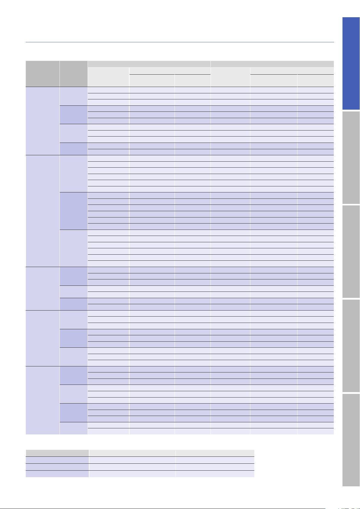
Packaged Sale Model Configuration
AC pulse input type
Bundled driver model number
:
FS1W075P00
Step angle
/
0.72
°
Rated current 0.75A
Model
Motor
flange size
Single shaft Double shafts
Set part
number
Set accessories
Set part
number
Set accessories
Motor model
number
Connector
number
Note)
Motor model
number
Connector
number
Note)
Standard
model
□
42mm
FSF551S 103F5505-7041 PM-AP-065 FSF551D 103F5505-7011 PM-AP-065
FSF552S 103F5508-7041 PM-AP-065 FSF552D 103F5508-7011 PM-AP-065
FSF554S 103F5510-7041 PM-AP-065 FSF554D 103F5510-7011 PM-AP-065
□
60mm
FSF781S 103F7851-7041 PM-AP-064 FSF781D 103F7851-7011 PM-AP-064
FSF782S 103F7852-7041 PM-AP-064 FSF782D 103F7852-7011 PM-AP-064
FSF783S 103F7853-7041 PM-AP-064 FSF783D 103F7853-7011 PM-AP-064
φ
86mm
FSF851S 103F8581-7041 PM-AP-064 FSF851D 103F8581-7011 PM-AP-064
FSF852S 103F8582-7041 PM-AP-064 FSF852D 103F8582-7011 PM-AP-064
FSF853S 103F8583-7041 PM-AP-064 FSF853D 103F8583-7011 PM-AP-064
φ
106mm
FSF892S 103F89582-7041 PM-AP-063 FSF892D 103F89582-7011 PM-AP-063
FSF893S 103F89583-7041 PM-AP-063 FSF893D 103F89583-7011 PM-AP-063
Low-backlash
gear model
□
42mm
FSF551S-CX3.6 103F5505-70CXA4 PM-AP-065 FSF551D-CX3.6 103F5505-70CXA1 PM-AP-065
FSF551S-CX7.2 103F5505-70CXB4 PM-AP-065 FSF551D-CX7.2 103F5505-70CXB1 PM-AP-065
FSF551S-CX10 103F5505-70CXE4 PM-AP-065 FSF551D-CX10 103F5505-70CXE1 PM-AP-065
FSF551S-CX20 103F5505-70CXG4 PM-AP-065 FSF551D-CX20 103F5505-70CXG1 PM-AP-065
FSF551S-CX30 10
3F5505-70CXJ4 PM-AP-065 FSF551D-CX30 103F5505-70CXJ1
PM-AP-065
FSF551S-CX36 103F5505-70CXK4 PM-AP-065 FSF551D-CX36 103F5505-70CXK1 PM-AP-065
□
60mm
FSF781S-CX3.6 103F7851-70CXA4 PM-AP-064 FSF781D-CX3.6 103F7851-70CXA1 PM-AP-064
FSF781S-CX7.2 103F7851-70CXB4 PM-AP-064 FSF781D-CX7.2 103F7851-70CXB1 PM-AP-064
FSF781S-CX10 103F7851-70CXE4 PM-AP-064 FSF781D-CX10 103F7851-70CXE1 PM-AP-064
FSF781S-CX20 103F7851-70CXG4 PM-AP-064 FSF781D-C
X20 103F7851-70CXG1 PM-AP-064
F
SF781S-CX30 103F7851-70CXJ4 PM-AP-064 FSF781D-CX30 103F7851-70CXJ1 PM-AP-064
FSF781S-CX36 103F7851-70CXK4 PM-AP-064 FSF781D-CX36 103F7851-70CXK1 PM-AP-064
φ
86mm
FSF851S-CX3.6 103F8581-70CXA4 PM-AP-064 FSF851D-CX3.6 103F8581-70CXA1 PM-AP-064
FSF851S-CX7.2 103F8581-70CXB4 PM-AP-064 FSF851D-CX7.2 103F8581-70CXB1 PM-AP-064
FSF851S-CX10 103F8581-70CXE4 PM-AP-064 FSF851D-CX10 103F8581-70CXE1 PM-AP-064
FSF8
51S-CX20 103F8581-70CXG4
PM-AP-064 FSF851D-CX20 103F8581-70CXG1 PM-AP-064
FSF851S-CX30 103F8581-70CXJ4 PM-AP-064 FSF851D-CX30 103F8581-70CXJ1 PM-AP-064
FSF851S-CX36 103F8581-70CXK4 PM-AP-064 FSF851D-CX36 103F8581-70CXK1 PM-AP-064
Harmonic
gear model
□
42mm
FSF551S-HX30 103F5505-70HXJ5 PM-AP-065 FSF551D-HX30 103F5505-70HXJ2 PM-AP-065
FSF551S-HX50 103F5505-70HXL5 PM-AP-065 FSF551D-HX50 103F5505-70HXL2 PM-AP-065
FSF551S-HX100 103F550
5-70HXM5 PM-AP-065 F
SF551D-HX100 103F5505-70HXM2 PM-AP-065
□
60mm
FSF781S-HX50 103F7851-70HXL4 PM-AP-064 FSF781D-HX50 103F7851-70HXL1 PM-AP-064
FSF781S-HX100 103F7851-70HXM4 PM-AP-064 FSF781D-HX100 103F7851-70HXM1 PM-AP-064
φ
86mm
FSF851S-HX50 103F8581-70HXL4 PM-AP-064 FSF851D-HX50 103F8581-70HXL1 PM-AP-064
FSF851S-HX100 103F8581-70HXM4 PM-AP-064 FSF851D-HX100 103F8581-70HXM1 PM-AP-064
Electromag-
netic brake
model
□
42mm
FSF551S-XB 103F5505-70XB41 PM-AP-065
− − −
FSF552S-XB 103F5508-70XB41 PM-AP-065
− − −
FSF554S-XB 103F5510-70XB41 PM-AP-065
− − −
□
60mm
FSF781S-XB 103F7851-70XB41 PM-AP-064
− − −
FSF782S-XB 103F7852-70XB41 PM-AP-064
− − −
FSF783S-XB 103F7853-70XB41 PM-AP-064
− − −
φ
86mm
FSF851S-XB 103F8581-70XB41 PM-AP-064
− − −
FSF852S-XB 103F8582-70XB41 PM-AP-064
− − −
FSF853S-XB 103F8583-70XB41 PM-AP-064
− − −
CE / UL
model
□
42mm
FSM551S 103M5505-7041 PM-AP-065 FSM551D 103M5505-7011 PM-AP-065
FSM552S 103M5508-7041 PM-AP-065 FSM552D 103M5508-7011 PM-AP-065
FSM554S 103M5510-7041 PM-AP-065 FSM554D 103M5510-7011 PM-AP-065
□
60mm
FSM781S 103M7851-7041 PM-AP-064 FSM781D 103M7851-7011 PM-AP-064
FSM782S 103M7852-7041 PM-AP-064 FSM782D 103M7852-7011 PM-AP-064
FSM783S 103M7853-7041 PM-AP-064 FSM783D 103M7853-7011 PM-AP-064
φ
86mm
FSM851S 103M8581-7041 PM-AP-064 FSM851D 103M8581-7011 PM-AP-064
FSM852S 103M8582-7041 PM-AP-064 FSM852D 103M8582-7011
PM-AP-064
FSM853S 103M8583-7041 PM-AP-064 FSM853D 103M8583-7011 PM-AP-064
φ
106mm
FSM892S 103M89582-7041 PM-AP-063 FSM892D 103M89582-7011 PM-AP-063
FSM893S 103M89583-7041 PM-AP-063 FSM893D 103M89583-7011 PM-AP-063
Note) Includes a driver connector set (power supply connector, input/output signal connector) and a motor connector.
Connector model number Driver connector set model number Motor connector model number
PM-AP-063 PM-AP-078 4838971-1
PM-AP-064 PM-AP-078 4837994-1
PM-AP-065 PM-AP-078 4835758-1
This is a set comprising a driver,
motor and connectors.
11
AC input
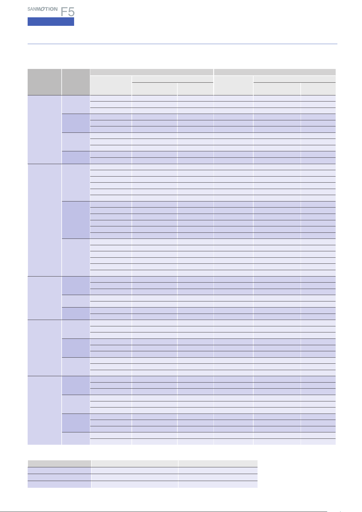
Specifications
5-phase STEPPING SYSTEMS
Type with built-in AC positioning function
Bundled driver model number : FP1W075P00
Step angle
/
0.72
°
Rated current 0.75A
Model
Motor
flange size
Single shaft Double shafts
Set part
number
Set accessories
Set part
number
Set accessories
Motor model
number
Connector
number
Note)
Motor model
number
Connector
number
Note)
Standard
model
□
42mm
FPF551S 103F5505-7041 PM-AP-074 FPF551D 103F5505-7011 PM-AP-074
FPF552S 103F5508-7041 PM-AP-074 FPF552D 103F5508-7011 PM-AP-074
FPF554S 103F5510-7041 PM-AP-074 FPF554D 103F5510-7011 PM-AP-074
□
60mm
FPF781S 103F7851-7041 PM-AP-073 FPF781D 103F7851-7011 PM-AP-073
FPF782S 103F7852-7041 PM-AP-073 FPF782D 103F7852-7011 PM-AP-073
FPF783S 103F7853-7041 PM-AP-073 FPF783D 103F7853-7011 PM-AP-073
φ
86mm
FPF851S 103F8581-7041 PM-AP-073 FPF851D 103F8581-7011 PM-AP-073
FPF852S 103F8582-7041 PM-AP-073 FPF852D 103F8582-7011 PM-AP-073
FPF853S 103F8583-7041 PM-AP-073 FPF853D 103F8583-7011 PM-AP-073
φ
106mm
FPF892S 103F89582-7041 PM-AP-072 FPF892D 103F89582-7011 PM-AP-072
FPF893S 103F89583-7041 PM-AP-072 FPF893D 103F89583-7011 PM-AP-072
Low-backlash
gear model
□
42mm
FPF551S-CX3.6 103F5505-70CXA4 PM-AP-074 FPF551D-CX3.6 103F5505-70CXA1 PM-AP-074
FPF551S-CX7.2 103F5505-70CXB4 PM-AP-074 FPF551D-CX7.2 103F5505-70CXB1 PM-AP-074
FPF551S-CX10 103F5505-70CXE4 PM-AP-074 FPF551D-CX10 103F5505-70CXE1 PM-AP-074
FPF551S-CX20 103F5505-70CXG4 PM-AP-074 FPF551D-CX20 103F5505-70CXG1 PM-AP-074
FPF551S-CX30 10
3F5505-70CXJ4 PM-AP-074 FPF551D-CX30 103F5505-70CXJ1
PM-AP-074
FPF551S-CX36 103F5505-70CXK4 PM-AP-074 FPF551D-CX36 103F5505-70CXK1 PM-AP-074
□
60mm
FPF781S-CX3.6 103F7851-70CXA4 PM-AP-073 FPF781D-CX3.6 103F7851-70CXA1 PM-AP-073
FPF781S-CX7.2 103F7851-70CXB4 PM-AP-073 FPF781D-CX7.2 103F7851-70CXB1 PM-AP-073
FPF781S-CX10 103F7851-70CXE4 PM-AP-073 FPF781D-CX10 103F7851-70CXE1 PM-AP-073
FPF781S-CX20 103F7851-70CXG4 PM-AP-073 FPF781D-C
X20 103F7851-70CXG1 PM-AP-073
F
PF781S-CX30 103F7851-70CXJ4 PM-AP-073 FPF781D-CX30 103F7851-70CXJ1 PM-AP-073
FPF781S-CX36 103F7851-70CXK4 PM-AP-073 FPF781D-CX36 103F7851-70CXK1 PM-AP-073
φ
86mm
FPF851S-CX3.6 103F8581-70CXA4 PM-AP-073 FPF851D-CX3.6 103F8581-70CXA1 PM-AP-073
FPF851S-CX7.2 103F8581-70CXB4 PM-AP-073 FPF851D-CX7.2 103F8581-70CXB1 PM-AP-073
FPF851S-CX10 103F8581-70CXE4 PM-AP-073 FPF851D-CX10 103F8581-70CXE1 PM-AP-073
FPF8
51S-CX20 103F8581-70CXG4
PM-AP-073 FPF851D-CX20 103F8581-70CXG1 PM-AP-073
FPF851S-CX30 103F8581-70CXJ4 PM-AP-073 FPF851D-CX30 103F8581-70CXJ1 PM-AP-073
FPF851S-CX36 103F8581-70CXK4 PM-AP-073 FPF851D-CX36 103F8581-70CXK1 PM-AP-073
Harmonic
gear model
□
42mm
FPF551S-HX30 103F5505-70HXJ5 PM-AP-074 FPF551D-HX30 103F5505-70HXJ2 PM-AP-074
FPF551S-HX50 103F5505-70HXL5 PM-AP-074 FPF551D-HX50 103F5505-70HXL2 PM-AP-074
FPF551S-HX100 103F550
5-70HXM5 PM-AP-074 F
PF551D-HX100 103F5505-70HXM2 PM-AP-074
□
60mm
FPF781S-HX50 103F7851-70HXL4 PM-AP-073 FPF781D-HX50 103F7851-70HXL1 PM-AP-073
FPF781S-HX100 103F7851-70HXM4 PM-AP-073 FPF781D-HX100 103F7851-70HXM1 PM-AP-073
φ
86mm
FPF851S-HX50 103F8581-70HXL4 PM-AP-073 FPF851D-HX50 103F8581-70HXL1 PM-AP-073
FPF851S-HX100 103F8581-70HXM4 PM-AP-073 FPF851D-HX100 103F8581-70HXM1 PM-AP-073
Electromag-
netic brake
model
□
42mm
FPF551S-XB 103F5505-70XB41 PM-AP-074
− − −
FPF552S-XB 103F5508-70XB41 PM-AP-074
− − −
FPF554S-XB 103F5510-70XB41 PM-AP-074
− − −
□
60mm
FPF781S-XB 103F7851-70XB41 PM-AP-073
− − −
FPF782S-XB 103F7852-70XB41 PM-AP-073
− − −
FPF783S-XB 103F7853-70XB41 PM-AP-073
− − −
φ
86mm
FPF851S-XB 103F8581-70XB41 PM-AP-073
− − −
FPF852S-XB 103F8582-70XB41 PM-AP-073
− − −
FPF853S-XB 103F8583-70XB41 PM-AP-073
− − −
CE / UL
model
□
42mm
FPM551S 103M5505-7041 PM-AP-074 FPM551D 103M5505-7011 PM-AP-074
FPM552S 103M5508-7041 PM-AP-074 FPM552D 103M5508-7011 PM-AP-074
FPM554S 103M5510-7041 PM-AP-074 FPM554D 103M5510-7011 PM-AP-074
□
60mm
FPM781S 103M7851-7041 PM-AP-073 FPM781D 103M7851-7011 PM-AP-073
FPM782S 103M7852-7041 PM-AP-073 FPM782D 103M7852-7011 PM-AP-073
FPM783S 103M7853-7041 PM-AP-073 FPM783D 103M7853-7011 PM-AP-073
φ
86mm
FPM851S 103M8581-7041 PM-AP-073 FPM851D 103M8581-7011 PM-AP-073
FPM852S 103M8582-7041 PM-AP-073 FPM852D 103M8582-7011
PM-AP-073
FPM853S 103M8583-7041 PM-AP-073 FPM853D 103M8583-7011 PM-AP-073
φ
106mm
FPM892S 103M89582-7041 PM-AP-072 FPM892D 103M89582-7011 PM-AP-072
FPM893S 103M89583-7041 PM-AP-072 FPM893D 103M89583-7011 PM-AP-072
Note) Includes a driver connector set (power supply connector, input/output signal connector) and a motor connector.
Connector model number Driver connector set model number Motor connector model number
PM-AP-072 PM-AP-079 4838971-1
PM-AP-073 PM-AP-079 4837994-1
PM-AP-074 PM-AP-079 4835758-1
Packaged Sale Model Configuration
This is a set comprising a driver,
motor and connectors.

12
AC inputInput / Output signal standardDC inputStepping motorDimensions
Size
Motor flange size
□
42
mm
(
□
1.65
inch
)
□
60
mm
(
□
2.36
inch
)
Motor leng th
49mm
(
1.93inch
)
46.5mm
(
1.83inch
)
55mm
(
2.17inch
)
87.5mm
(
3.45inch
)
Set par t
number
Single shaft
FSF55 4S FPF554S FSF781S FPF781S FSF782S FPF782S FSF783S FPF783S
Double shaft
FSF55 4D FPF554D FSF781D FPF781D FSF782D FPF782D FSF782D FPF783D
Holding torque N
・
m
(
oz
・
in
)
0.26
(
36.82
)
0.6
(
85.0
)
0.93
(
131.7
)
1.79
(
253.5
)
Rotor iner tia
×10
-4
kg・m
2
(oz・in
2
)
0.065
(
0.36
)
0.275
(
1.50
)
0.4
(
2.19
)
0.84
(
4.60
)
Mass
(
Weight
)
kg
(
lbs
)
0.37
(
0.81
)
0.6
(
1.32
)
0.78
(
1.72
)
1.36
(
3.0
)
Allowable thrust load N
(
lbs
)
10
(
2.25
)
20
(
4.5
)
20
(
4.5
)
20
(
4.5
)
Allowable radial l oad
(
Note 1
)
N
(
lbs
)
35
(
8.75
)
80
(
18
)
80
(
18
)
80
(
18
)
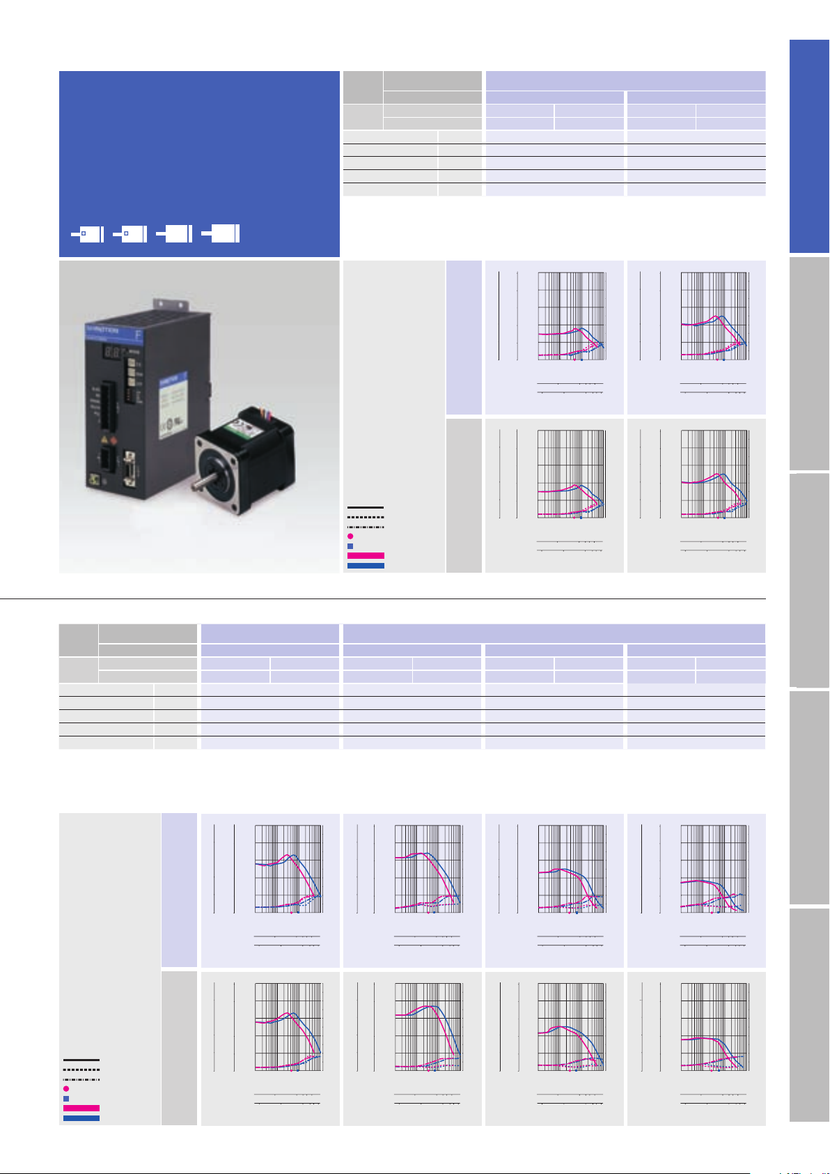
AC100V
AC200V
Standard model
F series driver + F series motor
42
60
86
106
φ φ
(
φ
4.17inch)(
φ
3.39inch)(
□
2.35inch)(
□
1.65inch)
Size
Motor flange size
□
42
mm
(
□
1.65
inch
)
Motor leng th
34mm
(
1.34inch
)
40mm
(
1.57inch
)
Set par t
number
Single shaft
FSF551S FPF551S FSF552S FPF552S
Double shaft
FSF551D FPF551D FSF552D FPF552D
Holding torque N
・
m
(
oz
・
in
)
0.13
(
18.41
)
0.18
(
25.49
)
Rotor iner tia
×10
-4
kg・m
2
(oz・in
2
)
0.03
(
0.16
)
0.053
(
0.29
)
Mass
(
Weight
)
kg
(
lbs
)
0.23
(
0.50
)
0.28
(
0.62
)
Allowable thrust load N
(
lbs
)
10
(
2.25
)
10
(
2.25
)
Allowable radial l oad
(
Note 1
)
N
(
lbs
)
35
(
8.75
)
35
(
8.75
)
(
Note1
)
When loa d is applied at 1/ 3 length from output s haft edge .
(
Note1
)
When loa d is applied at 1/ 3 length from output s haft edge .
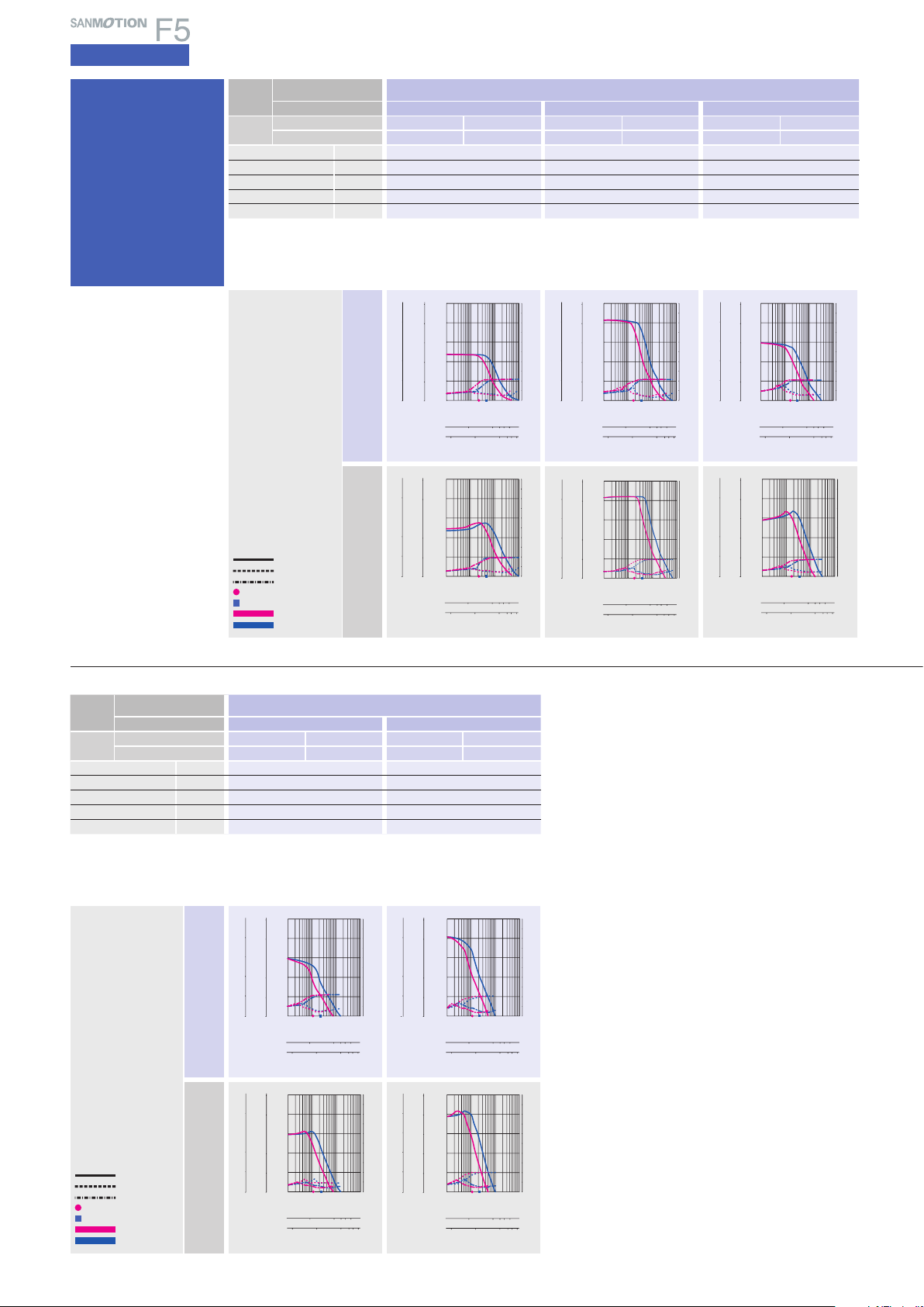
Motor flange size
Pull-out torque
Source current (load applied)
Source current (no load)
Fs:
Maximum self-start
frequency when not loaded
1-division
2-division
Operating current:
0.75A/phase
1-division fs
2-division fs
0
0
0.1
0.2
0.3
0.4
0.5
0.1 110 100
0
1
2
3
4
5
6
7
8
9
10
5
4
3
2
1
4
3
2
1
Torque( kgf・cm )
0
Torque( lb-in )
Torque(N・m )
Source current (A)
Pulse rate (kpulse/s)
100 1000 2000 3000 5000
Number of rotations (min
-1
)
1-division
2-division
10 100 1000 2000 3000 5000
0
0
0.1
0.2
0.3
0.4
0.5
0.1 110 100
0
1
2
3
4
5
6
7
8
9
10
5
4
3
2
1
4
3
2
1
Torque( kgf・cm )
0
Torque( lb-in )
Torque(N・m )
Source current (A)
Pulse rate (kpulse/s)
100 1000 2000 3000 5000
Number of rotations (min
-1
)
1-division
2-division
10 100 1000 2000 3000 5000
0
0
0.1
0.2
0.3
0.4
0.5
0.1 110 100
0
1
2
3
4
5
6
7
8
9
10
5
4
3
2
1
4
3
2
1
Torque( kgf・cm )
0
Torque( lb-in )
Torque(N・m )
Source current (A)
Pulse rate (kpulse/s)
100 1000 2000 3000 5000
Number of rotations (min
-1
)
1-division
2-division
10 100 1000 2000 3000 5000
0
0
0.1
0.2
0.3
0.4
0.5
0.1 110 100
0
1
2
3
4
5
6
7
8
9
10
5
4
3
2
1
4
3
2
1
Torque( kgf・cm )
0
Torque( lb-in )
Torque(N・m )
Source current (A)
Pulse rate (kpulse/s)
100 1000 2000 3000 5000
Number of rotations (min
-1
)
1-division
2-division
10 100 1000 2000 3000 5000
0
0
0.1
0.2
0.3
0.4
0.5
0.1 110 100
0
1
2
3
4
5
6
7
8
9
10
5
4
3
2
1
4
3
2
1
Torque( kgf・cm )
0
Torque( lb-in )
Torque(N・m )
Source current (A)
Pulse rate (kpulse/s)
100 1000 2000 3000 5000
Number of rotations (min
-1
)
1-division
2-division
10 100 1000 2000 3000 5000
0
0
0.1
0.2
0.3
0.4
0.5
0.1 110 100
0
1
2
3
4
5
6
7
8
9
10
5
4
3
2
1
4
3
2
1
Torque( kgf・cm )
0
Torque( lb-in )
Torque(N・m )
Source current (A)
Pulse rate (kpulse/s)
100 1000 2000 3000 5000
Number of rotations (min
-1
)
1-division
2-division
10 100 1000 2000 3000 5000
0
0
0.2
0.4
0.6
0.8
1.0
0.1 110 100
0
1
2
3
4
5
6
7
8
9
10
10
8
6
4
2
8
6
4
2
Torque( kgf・cm )
0
Torque( lb-in )
Torque(N・m )
Pulse rate (kpulse/s)
100 1000 2000 3000 5000
Number of rotations (min
-1
)
1-division
2-division
10 100 1000 2000 3000 5000
Source current (A)
0
0
0.2
0.4
0.5
0.8
1.0
0.1 110 100
0
1
2
3
4
5
6
7
8
9
10
10
8
6
4
2
8
6
4
2
Torque( kgf・cm )
0
Torque( lb-in )
Torque(N・m )
Source current (A)
Pulse rate (kpulse/s)
100 1000 2000 3000 5000
Number of rotations (min
-1
)
1-division
2-division
10 100 1000 2000 3000 5000
0
0
0.4
0.8
1.2
1.6
2.0
0.1 110 100
0
1
2
3
4
5
6
7
8
9
10
20
16
12
8
4
16
12
8
4
Torque( kgf・cm )
0
Torque( lb-in )
Torque(N・m )
Source current (A)
Pulse rate (kpulse/s)
100 1000 2000 3000 5000
Number of rotations (min
-1
)
1-division
2-division
10 100 1000 2000 3000 5000
0
0
0.4
0.8
1.2
1.6
2.0
0.1 110 100
0
1
2
3
4
5
6
7
8
9
10
20
16
12
8
4
16
12
8
4
Torque( kgf・cm )
0
Torque( lb-in )
Torque(N・m )
Source current (A)
Pulse rate (kpulse/s)
100 1000 2000 3000 5000
Number of rotations (min
-1
)
1-division
2-division
10 100 1000 2000 3000 5000
AC100V
AC200V
Pull-out torque
Source current (load applied)
Source current (no load)
Fs:
Maximum self-start
frequency when not loaded
1-division
2-division
Operating current:
0.75A/phase
1-division fs
2-division fs
The data a re measured und er the drive c ondition of o ur company. Th e drive
torque may ver y depending on the acc uracy of cust omer-side e quipment.
The data a re measured und er the drive c ondition of o ur company. Th e drive torque m ay very dep ending on th e accuracy o f customer-s ide equipm ent.
0
0
1
2
3
4
5
0.1 110 100
0
1
2
3
4
5
6
7
8
9
10
50
40
30
20
10
40
30
20
10
Torque( kgf・cm )
0
Torque( lb-in )
Torque(N・m )
Source current (A)
Pulse rate (kpulse/s)
100 1000 2000 3000 5000
Number of rotations (min
-1
)
1-division
2-division
10 100 1000 2000 3000 5000
0
0
1
2
3
4
5
0.1 110 100
0
1
2
3
4
5
6
7
8
9
10
50
40
30
20
10
40
30
20
10
Torque( kgf・cm )
0
Torque( lb-in )
Torque(N・m )
Source current (A)
Pulse rate (kpulse/s)
100 1000 2000 3000 5000
Number of rotations (min
-1
)
1-division
2-division
10 100 1000 2000 3000 5000
13
AC input
Specifications
5-phase STEPPING SYSTEMS
0
0
4
8
12
16
20
0.1 110 100
0
1
2
3
4
5
6
7
8
9
10
200
160
120
80
40
160
120
80
40
Torque( kgf・cm )
0
Torque( lb-in )
Torque(N・m )
Source current (A)
Pulse rate (kpulse/s)
100 1000 2000 3000 5000
Number of rotations (min
-1
)
1-division
2-division
10 100 1000 2000 3000 5000
0
0
4
8
12
16
20
0.11 10 100
0
1
2
3
4
5
6
7
8
9
10
200
160
120
80
40
160
120
80
40
Torque( kgf・cm )
0
Torque( lb-in )
Torque(N・m )
Source current (A)
Pulse rate (kpulse/s)
100 1000 2000 3000 5000
Number of rotations (min
-1
)
1-division
2-division
10 100 1000 2000 3000 5000
0
0
4
8
12
16
20
0.1 110 100
0
1
2
3
4
5
6
7
8
9
10
200
160
120
80
40
160
120
80
40
Torque( kgf・cm )
0
Torque( lb-in )
Torque(N・m )
Source current (A)
Pulse rate (kpulse/s)
100 1000 2000 3000 5000
Number of rotations (min
-1
)
1-division
2-division
10 100 1000 2000 3000 5000
0
0
4
8
12
16
20
0.1 110 100
0
1
2
3
4
5
6
7
8
9
10
200
160
120
80
40
160
120
80
40
Torque( kgf・cm )
0
Torque( lb-in )
Torque(N・m )
Source current (A)
Pulse rate (kpulse/s)
100 1000 2000 3000 5000
Number of rotations (min
-1
)
1-division
2-division
10 100 1000 2000 3000 5000
AC100V
AC200V
Pull-out torque
Source current (load applied)
Source current (no load)
Fs:
Maximum self-start
frequency when not loaded
1-division
2-division
Operating current:
0.75A/phase
1-division fs
2-division fs
0
0
2
4
6
8
10
0.1 110 100
0
1
2
3
4
5
6
7
8
9
10
100
80
60
40
20
80
60
40
20
Torque( kgf・cm )
0
Torque( lb-in )
Torque(N・m )
Source current (A)
Pulse rate (kpulse/s)
100 1000 2000 3000 5000
Number of rotations (min
-1
)
1-division
2-division
10 100 1000 2000 3000 5000
0
0
2
4
6
8
10
0.1 110 100
0
1
2
3
4
5
6
7
8
9
10
100
80
60
40
20
80
60
40
20
Torque( kgf・cm )
0
Torque( lb-in )
Torque(N・m )
Source current (A)
Pulse rate (kpulse/s)
100 1000 2000 3000 5000
Number of rotations (min
-1
)
1-division
2-division
10 100 1000 2000 3000 5000
0
0
1
2
3
4
5
0.1 110 100
0
1
2
3
4
5
6
7
8
9
10
50
40
30
20
10
40
30
20
10
0
Torque( kgf・cm )
Torque( lb-in )
Torque(N・m )
Source current (A)
Pulse rate (kpulse/s)
100 1000 2000 3000 5000
Number of rotations (min
-1
)
1-division
2-division
10 100 1000 2000 3000 5000
Torque(N・m )
Source current (A)
Pulse rate (kpulse/s)
1-division
2-division
Number of rotations (min
-1
)
0
1
2
3
4
5
0
1
2
3
4
5
6
7
8
9
10
0.1 110 100
100 1000 2000 30005000
10 100 1000 200030005000
0
50
40
30
20
10
40
30
20
10
Torque( kgf・cm )
0
Torque( lb-in )
0
0
1
2
3
4
5
0.1 110 100
0
1
2
3
4
5
6
7
8
9
10
50
40
30
20
10
40
30
20
10
Torque( kgf・cm )
0
Torque( lb-in )
Torque(N・m )
Source current (A)
Pulse rate (kpulse/s)
100 1000 2000 3000 5000
Number of rotations (min
-1
)
1-division
2-division
10 100 1000 2000 3000 5000
0
0
1
2
3
4
5
0.11 10 100
0
1
2
3
4
5
6
7
8
9
10
50
40
30
20
10
40
30
20
10
Torque( kgf・cm )
0
Torque( lb-in )
Torque(N・m )
Source current (A)
Pulse rate (kpulse/s)
100 1000 2000 3000 5000
Number of rotations (min
-1
)
1-division
2-division
10 100 1000 2000 3000 5000
AC100V
AC200V
Pull-out torque
Source current (load applied)
Source current (no load)
Fs:
Maximum self-start
frequency when not loaded
1-division
2-division
Operating current:
0.75A/phase
1-division fs
2-division fs
Size
Motor flange size
φ
106
mm
(
φ
4.17
inch
)
Motor leng th
163.3mm
(
6.43inch
)
221.3mm
(
8.71inch
)
Set par t
number
Single shaft
FSF892S FPF892S FSF893S FPF893S
Double shaft
FSF892D FPF892D FSF893D FPF893D
Holding torque N
・
m
(
oz
・
in
)
10.8
(
1529.4
)
16
(
2265.7
)
Rotor iner tia
×10
-4
kg・m
2
(oz・in
2
)
14.6
(
79.83
)
22
(
120.28
)
Mass
(
Weight
)
kg
(
lbs
)
7.5
(
16.5
)
10.5
(
23.1
)
Allowable thrust load N
(
lbs
)
100
(
22.5
)
100
(
22.5
)
Allowable radial l oad
(
Note 1
)
N
(
lbs
)
360
(
81
)
360
(
81
)
Size
Motor flange size
φ
86
mm
(
φ
3.39
inch
)
Motor leng th
62.15mm
(
2.47inch
)
92.2mm
(
3.63inch
)
125.85mm
(
4.95inch
)
Set par t
number
Single shaft
FSF851S FPF851S FSF852S FPF852S FSF853S FPF853S
Double shaft
FSF851D FPF851D FSF852D FPF852D FSF853D FPF8 53D
Holding torque N
・
m
(
oz
・
in
)
2.06
(
291.7
)
4.02
(
569. 3
)
6.17
(
873.7
)
Rotor iner tia
×10
-4
kg・m
2
(oz・in
2
)
1.45
(
7.93
)
2.9
(
15.86
)
4.4
(
24.06
)
Mass
(
Weight
)
kg
(
lbs
)
1.5
(
3.3
)
2.5
(
5.5
)
3.5
(
7.7
)
Allowable thrust load N
(
lbs
)
60
(
13.5
)
60
(
13.5
)
60
(
13.5
)
Allowable radial l oad
(
Note 1
)
N
(
lbs
)
220
(
49.5
)
220
(
49.5
)
220
(
49.5
)
(
Note1
)
When loa d is applied at 1/ 3 length from output s haft edge .
(
Note1
)
When loa d is applied at 1/ 3 length from output s haft edge .
The data a re measured und er the drive c ondition of o ur company. Th e drive
torque may ver y depending on the acc uracy of cust omer-side e quipment.
The data a re measured und er the drive c ondition of o ur company. Th e drive torque m ay very dep ending on the a ccuracy o f customer-s ide equipm ent.
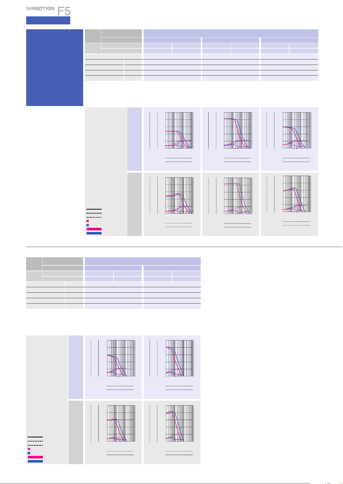
Standard
model
F series driver + F series motor
14
AC inputInput / Output signal standardDC inputStepping motorDimensions
CE / UL model
F series driver + M series motor
Size
Motor flange size
□
42
mm
(
□
1.65
inch
)
Motor leng th
31mm
(
1.22inch
)
50.5mm
(
1.99inch
)
Set par t
number
Single shaft
FSM551S FPM551S FSM552S FPM552S
Double shaft
FSM551D FPM551D FSM552D FPM552D
Holding torque N
・
m
(
oz
・
in
)
0.13
(
18.41
)
0.18
(
25.49
)
Rotor iner tia
×10
-4
kg・m
2
(oz・in
2
)
0.03
(
0.16
)
0.053
(
0.29
)
Mass
(
Weight
)
kg
(
lbs
)
0.23
(
0.51
)
0.28
(
0.62
)
Allowable thrust load N
(
lbs
)
10
(
2.25
)
10
(
2.25
)
Allowable radial l oad
(
Note 1
)
N
(
lbs
)
35
(
8.75
)
35
(
8.75
)
(
Note1
)
When loa d is applied at 1/ 3 length from output s haft edge .
42
60
86
106
φ φ
(
φ
4.17inch)(
φ
3.39inch)(
□
2.35inch)(
□
1.65inch)
Motor flange size
AC100V
AC200V
Pull-out torque
Source current (load applied)
Source current (no load)
Fs:
Maximum self-start
frequency when not loaded
1-division
2-division
Operating current:
0.75A/phase
1-division fs
2-division fs
0
0
0.1
0.2
0.3
0.4
0.5
0.1 110 100
0
1
2
3
4
5
6
7
8
9
10
5
4
3
2
1
4
3
2
1
0
Torque( kgf・cm )
Torque( lb-in )
Torque(N・m )
Source current (A)
Pulse rate (kpulse/s)
100 1000 2000 3000 5000
Number of rotations (min
-1
)
1-division
2-division
10 100 1000 2000 3000 5000
0
0
0.1
0.2
0.3
0.4
0.5
0.1 110 100
0
1
2
3
4
5
6
7
8
9
10
5
4
3
2
1
4
3
2
1
0
Torque( kgf・cm )
Torque( lb-in )
Torque(N・m )
Source current (A)
Pulse rate (kpulse/s)
100 1000 2000 3000 5000
Number of rotations (min
-1
)
1-division
2-division
10 100 1000 2000 3000 5000
0
0
0.1
0.2
0.3
0.4
0.5
0.1 110 100
0
1
2
3
4
5
6
7
8
9
10
5
4
3
2
1
4
3
2
1
0
Torque( kgf・cm )
Torque( lb-in )
Torque(N・m )
Source current (A)
Pulse rate (kpulse/s)
100 1000 2000 3000 5000
Number of rotations (min
-1
)
1-division
2-division
10 100 1000 2000 3000 5000
0
0
0.1
0.2
0.3
0.4
0.5
0.1 110 100
0
1
2
3
4
5
6
7
8
9
10
5
4
3
2
1
4
3
2
1
0
Torque( kgf・cm )
Torque( lb-in )
Torque(N・m )
Source current (A)
Pulse rate (kpulse/s)
100 1000 2000 3000 5000
Number of rotations (min
-1
)
1-division
2-division
10 100 1000 2000 3000 5000
0
0
0.1
0.2
0.3
0.4
0.5
0.1 110 100
0
1
2
3
4
5
6
7
8
9
10
5
4
3
2
1
4
3
2
1
0
Torque( kgf・cm )
Torque( lb-in )
Torque(N・m )
Source current (A)
Pulse rate (kpulse/s)
100 1000 2000 3000 5000
Number of rotations (min
-1
)
1-division
2-division
10 100 1000 2000 3000 5000
0
0
0.1
0.2
0.3
0.4
0.5
0.1 110 100
0
1
2
3
4
5
6
7
8
9
10
5
4
3
2
1
4
3
2
1
0
Torque( kgf・cm )
Torque( lb-in )
Torque(N・m )
Source current (A)
Pulse rate (kpulse/s)
100 1000 2000 3000 5000
Number of rotations (min
-1
)
1-division
2-division
10 100 1000 2000 3000 5000
0
0
0.2
0.4
0.6
0.8
1.0
0.1 110 100
0
1
2
3
4
5
6
7
8
9
10
10
8
6
4
2
8
6
4
2
0
Torque( kgf・cm )
Torque( lb-in )
Torque(N・m )
Source current (A)
Pulse rate (kpulse/s)
100 1000 2000 3000 5000
Number of rotations (min
-1
)
1-division
2-division
10 100 1000 2000 3000 5000
0
0
0.2
0.4
0.6
0.8
1.0
0.1 110 100
0
1
2
3
4
5
6
7
8
9
10
10
8
6
4
2
8
6
4
2
0
Torque( kgf・cm )
Torque( lb-in )
Torque(N・m )
Source current (A)
Pulse rate (kpulse/s)
100 1000 2000 3000 5000
Number of rotations (min
-1
)
1-division
2-division
10 100 1000 2000 3000 5000
0
0
0.4
0.8
1.2
1.6
2.0
0.1 110 100
0
1
2
3
4
5
6
7
8
9
10
20
16
12
8
4
16
12
8
4
0
Torque( kgf・cm )
Torque( lb-in )
Torque(N・m )
Source current (A)
Pulse rate (kpulse/s)
100 1000 2000 3000 5000
Number of rotations (min
-1
)
1-division
2-division
10 100 1000 2000 3000 5000
0
0
0.4
0.8
1.2
1.6
2.0
0.1 110 100
0
1
2
3
4
5
6
7
8
9
10
20
16
12
8
4
16
12
8
4
0
Torque( kgf・cm )
Torque( lb-in )
Torque(N・m )
Source current (A)
Pulse rate (kpulse/s)
100 1000 2000 3000 5000
Number of rotations (min
-1
)
1-division
2-division
10 100 1000 2000 3000 5000
0
0
1
2
3
4
5
0.1 110 100
0
1
2
3
4
5
6
7
8
9
10
50
40
30
20
10
40
30
20
10
0
Torque( kgf・cm )
Torque( lb-in )
Torque(N・m )
Source current (A)
Pulse rate (kpulse/s)
100 1000 2000 3000 5000
Number of rotations (min
-1
)
1-division
2-division
10 100 1000 2000 3000 5000
0
0
1
2
3
4
5
0.1 110 100
0
1
2
3
4
5
6
7
8
9
10
50
40
30
20
10
40
30
20
10
0
Torque( kgf・cm )
Torque( lb-in )
Torque(N・m )
Source current (A)
Pulse rate (kpulse/s)
100 1000 2000 3000 5000
Number of rotations (min
-1
)
1-division
2-division
10 100 1000 2000 3000 5000
The data a re measured und er the drive c ondition of o ur company. Th e drive
torque may ver y depending on the acc uracy of cust omer-side e quipment.
AC100V
AC200V
Pull-out torque
Source current (load applied)
Source current (no load)
Fs:
Maximum self-start
frequency when not loaded
1-division
2-division
Operating current:
0.75A/phase
1-division fs
2-division fs
Size
Motor flange size
□
42
mm
(
□
1.65
inch
)
□
60
mm
(
□
2.36
inch
)
Motor leng th
49mm
(
1.93inch
)
46.5mm
(
1.83inch
)
55mm
(
2.17inch
)
87.5mm
(
3.44inch
)
Set par t
number
Single shaft
FSM554S FPM554S FSM781S FPM781S FSM782S FPM782S FSM783S FPM783S
Double shaft
FSM554D FPM554D FSM781D FPM781D FSM782D FPM782D
FSM783D FPM78 3D
Holding torque N
・
m
(
oz
・
in
)
0.26
(
36.82
)
0.6
(
85.0
)
0.065
(
9.20
)
1.79
(
253.5
)
Rotor iner tia
×10
-4
kg・m
2
(oz・in
2
)
0.065
(
0.36
)
0.275
(
1.50
)
0.016
(
0.09
)
0.84
(
4.59
)
Mass
(
Weight
)
kg
(
lbs
)
0.37
(
0.81
)
0.6
(
1.32
)
0.2
(
0.44
)
1.36
(
3.0
)
Allowable thrust load N
(
lbs
)
10
(
2.25
)
20
(
4.5
)
3
(
0.68
)
20
(
4.5
)
Allowable radial l oad
(
Note 1
)
N
(
lbs
)
35
(
8.75
)
80
(
18
)
34
(
7.65
)
80
(
18
)
(
Note1
)
When loa d is applied at 1/ 3 length from output s haft edge .
The data a re measured und er the drive c ondition of o ur company. Th e drive torque m ay very dep ending on th e accuracy o f customer-s ide equipm ent.
15
AC input
Specifications
5-phase STEPPING SYSTEMS
The data a re measured und er the drive c ondition of o ur company. Th e drive
torque may ver y depending on the acc uracy of cust omer-side e quipment.
Size
Motor flange size
φ
106
mm
(
φ
4.17
inch
)
Motor leng th
163.3mm
(
6.43inch
)
221.3mm
(
8.71inch
)
Set par t
number
Single shaft
FSM892S FPM892S FSM893S FPM8 93S
Double shaft
FSM892D FPM892D FSM893D FPM893D
Holding torque N
・
m
(
oz
・
in
)
10.8
(
1529.4
)
16
(
2265.7
)
Rotor iner tia
×10
-4
kg・m
2
(oz・in
2
)
14.6
(
79.83
)
22
(
120.28
)
Mass
(
Weight
)
kg
(
lbs
)
7.5
(
16.5
)
10.5
(
23.1
)
Allowable thrust load N
(
lbs
)
100
(
22.5
)
100
(
22.5
)
Allowable radial l oad
(
Note 1
)
N
(
lbs
)
360
(
81
)
360
(
81
)
(
Note1
)
When loa d is applied at 1/ 3 length from output s haft edge .
AC100V
AC200V
Pull-out torque
Source current (load applied)
Source current (no load)
Fs:
Maximum self-start
frequency when not loaded
1-division
2-division
Operating current:
0.75A/phase
1-division fs
2-division fs
0
0
1
2
3
4
5
0.1 110 100
0
1
2
3
4
5
6
7
8
9
10
50
40
30
20
10
40
30
20
10
0
Torque( kgf・cm )
Torque( lb-in )
Torque(N・m )
Source current (A)
Pulse rate (kpulse/s)
100 1000 2000 3000 5000
Number of rotations (min
-1
)
1-division
2-division
10 100 1000 2000 3000 5000
Torque(N・m )
Source current (A)
Pulse rate (kpulse/s)
1-division
2-division
Number of rotations (min
-1
)
0
1
2
3
4
5
0
1
2
3
4
5
6
7
8
9
10
0.1 110 100
100 1000 2000 30005000
10 100 1000 200030005000
0
50
40
30
20
10
40
30
20
10
Torque( kgf・cm )
0
Torque( lb-in )
0
0
2
4
6
8
10
0.1 110 100
0
1
2
3
4
5
6
7
8
9
10
100
80
60
40
20
80
60
40
20
0
Torque( kgf・cm )
Torque( lb-in )
Torque(N・m )
Source current (A)
Pulse rate (kpulse/s)
100 1000 2000 3000 5000
Number of rotations (min
-1
)
1-division
2-division
10 100 1000 2000 3000 5000
0
0
2
4
6
8
10
0.1 110 100
0
1
2
3
4
5
6
7
8
9
10
100
80
60
40
20
80
60
40
20
0
Torque( kgf・cm )
Torque( lb-in )
Torque(N・m )
Source current (A)
Pulse rate (kpulse/s)
100 1000 2000 3000 5000
Number of rotations (min
-1
)
1-division
2-division
10 100 1000 2000 3000 5000
0
0
4
8
12
16
20
0.1 110 100
0
1
2
3
4
5
6
7
8
9
10
0
200
160
120
80
40
160
120
80
40
Torque( kgf・cm )
Torque( lb-in )
Torque(N・m )
Source current (A)
Pulse rate (kpulse/s)
100 1000 2000 3000 5000
Number of rotations (min
-1
)
1-division
2-division
10 100 1000 2000 3000 5000
0
0
4
8
12
16
20
0.1 110 100
0
1
2
3
4
5
6
7
8
9
10
200
160
120
80
40
160
120
80
40
Torque( kgf・cm )
0
Torque( lb-in )
Torque(N・m )
Source current (A)
Pulse rate (kpulse/s)
100 1000 2000 3000 5000
Number of rotations (min
-1
)
1-division
2-division
10 100 1000 2000 3000 5000
0
0
4
8
12
16
20
0.1 110 100
0
1
2
3
4
5
6
7
8
9
10
200
160
120
80
40
160
120
80
40
0
Torque( kgf・cm )
Torque( lb-in )
Torque(N・m )
Source current (A)
Pulse rate (kpulse/s)
100 1000 2000 3000 5000
Number of rotations (min
-1
)
1-division
2-division
10 100 1000 2000 3000 5000
0
0
4
8
12
16
20
0.1 110 100
0
1
2
3
4
5
6
7
8
9
10
200
160
120
80
40
160
120
80
40
0
Torque( kgf・cm )
Torque( lb-in )
Torque(N・m )
Source current (A)
Pulse rate (kpulse/s)
100 1000 2000 3000 5000
Number of rotations (min
-1
)
1-division
2-division
10 100 1000 2000 3000 5000
The data a re measured und er the drive c ondition of o ur company. Th e drive torque m ay very dep ending on th e accuracy o f customer-s ide equipm ent.
Size
Motor flange size
φ
86
mm
(
φ
3.39
inch
)
Motor leng th
62.15mm
(
2.47inch
)
92.2mm
(
3.63inch
)
125.85mm
(
4.95inch
)
Set par t
number
Single shaft
FSM851S FPM851S FSM852S FPM852S FSM8 53S FPM853S
Double shaft
FSM851D FPM851D FSM852D FPM852D FSM853D FPM853D
Holding torque N
・
m
(
oz
・
in
)
2.06
(
291.7
)
4.02
(
569. 3
)
6.17
(
873.7
)
Rotor iner tia
×10
-4
kg・m
2
(oz・in
2
)
1.45
(
7.93
)
2.9
(
15.86
)
4.4
(
24.06
)
Mass
(
Weight
)
kg
(
lbs
)
1.5
(
3.3
)
2.5
(
5.5
)
3.5
(
7.7
)
Allowable thrust load N
(
lbs
)
60
(
13.5
)
60
(
13.5
)
60
(
13.5
)
Allowable radial l oad
(
Note 1
)
N
(
lbs
)
220
(
49.5
)
220
(
49.5
)
220
(
49.5
)
0
0
1
2
3
4
5
0.1 110 100
0
1
2
3
4
5
6
7
8
9
10
0
50
40
30
20
10
40
30
20
10
Torque( kgf・cm )
Torque( lb-in )
Torque(N・m )
Source current (A)
Pulse rate (kpulse/s)
100 1000 2000 3000 5000
Number of rotations (min
-1
)
1-division
2-division
10 100 1000 2000 3000 5000
0
0
1
2
3
4
5
0.1 110 100
0
1
2
3
4
5
6
7
8
9
10
50
40
30
20
10
40
30
20
10
0
Torque( kgf・cm )
Torque( lb-in )
Torque(N・m )
Source current (A)
Pulse rate (kpulse/s)
100 1000 2000 3000 5000
Number of rotations (min
-1
)
1-division
2-division
10 100 1000 2000 3000 5000
AC100V
AC200V
Pull-out torque
Source current (load applied)
Source current (no load)
Fs:
Maximum self-start
frequency when not loaded
1-division
2-division
Operating current:
0.75A/phase
1-division fs
2-division fs
(
Note1
)
When loa d is applied at 1/ 3 length from output s haft edge .
CE / UL
model
F series driver + M series motor
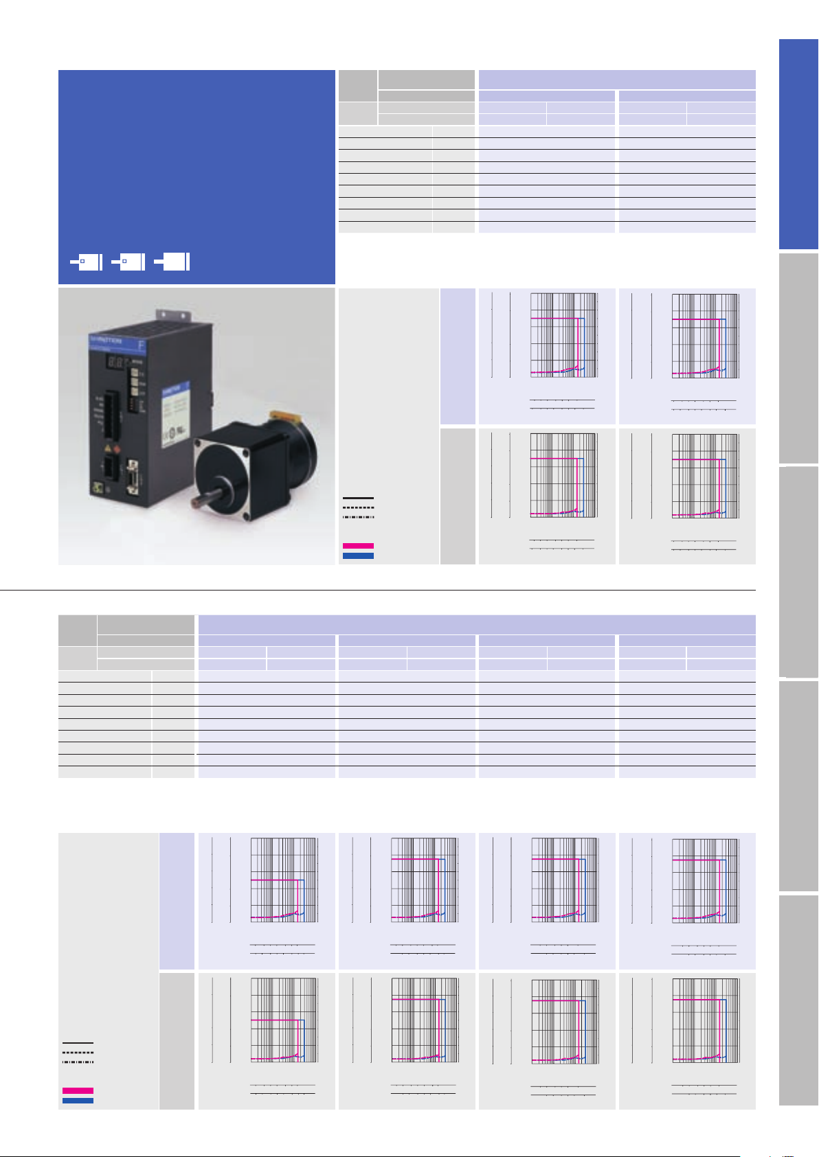
16
AC inputInput / Output signal standardDC inputStepping motorDimensions
AC100V
AC200V
Low-backlash gear
model
F series driver +
F series motor with low-backlash gear
Size
Motor flange size
□
42
mm
(
□
1.65
inch
)
Motor + gear length
64.5mm
(
2.54inch
)
64.5mm
(
2.54inch
)
Set par t
number
Single shaft
FSF551S-CX3.6 FPF551S-CX3.6 FSF551S-CX7.2 FPF551S-CX7.2
Double shaft
FSF551D-CX3.6 FPF551D-CX3.6 FSF551D-CX7.2 FPF551D-CX7.2
Allowable torque N
・
m
(
oz
・
in
)
0.343
(
48.6
)
0.686
(
97.1
)
Rotor iner tia
×10
-4
kg・m
2
(oz・in
2
)
0.03
(
0.16
)
0.03
(
0.16
)
Basic step angle 0.2 0.1
Gear rati o 1
:
3.6 1
:
7.2
Backlash DEG 0.6 0.4
Allowable speed min
-1
500 250
Mass
(
Weight
)
kg
(
lbs
)
0.36
(
0.79
)
0.36
(
0.79
)
Allowable thrust load N
(
lbs
)
15
(
3.38
)
15
(
3.38
)
Allowable
radial load
(
Note 1
)
N
(
lbs
)
20
(
4.5
)
20
(
4.5
)
Directio ns of motor rotat ion and gear o utput shaf t are the same fo r models wit h reductio n ratio 1 : 3.6 , 1 : 7.2, and 1 : 10
opposite f or reductio n ratio 1 : 20, 1 : 3 0, and 1 : 36 .
(
Note1
)
When loa d is applied at 1/ 3 length from output s haft edge .
42
60
86
106
φ
φ
(
φ
4.17inch)
(
φ
3.39inch
)
(
□
2.35inch)(
□
1.65inch)
Allowable torque
Source current (load applied)
Source current (no load)
1-division
2-division
Operating current:
0.75A/phase
5102050 100 200 500
52 102050 100 200
500
0
0
0.1
0.2
0.3
0.4
0.5
0.11 10 100
0
1
2
3
4
5
6
7
8
9
10
5
4
3
2
1
4
3
2
1
0
Torque( kgf・cm )
Torque( lb-in )
Torque(N・m )
Source current (A)
Pulse rate (kpulse/s)
Number of rotations (min
-1
)
1-division
2-division
12 5102050 100
100 250
2510 20 50
250
0
0
0.2
0.4
0.6
0.8
1.0
0.1 110 100
0
1
2
3
4
5
6
7
8
9
10
10
8
6
4
2
8
6
4
2
0
Torque( kgf・cm )
Torque( lb-in )
Torque(N・m )
Source current (A)
Pulse rate (kpulse/s)
1-division
2-division
Number of rotations (min
-1
)
5102050 100 200 500
52 102050 100 200
500
0
0
0.1
0.2
0.3
0.4
0.5
0.1 110 100
0
1
2
3
4
5
6
7
8
9
10
5
4
3
2
1
4
3
2
1
0
Torque( kgf・cm )
Torque( lb-in )
Torque(N・m )
Source current (A)
Pulse rate (kpulse/s)
Number of rotations (min
-1
)
1-division
2-division
12 5102050 100
100 250
2510 20 50
250
0
0
0.2
0.4
0.6
0.8
1.0
0.1 110 100
0
1
2
3
4
5
6
7
8
9
10
10
8
6
4
2
8
6
4
2
0
Torque( kgf・cm )
Torque( lb-in )
Torque(N・m )
Source current (A)
Pulse rate (kpulse/s)
1-division
2-division
Number of rotations (min
-1
)
2510 20 50 100 180
21 5 10 20 50 100
180
0
0
0.4
0.8
1.2
1.6
2.0
0.1 110 100
0
1
2
3
4
5
6
7
8
9
10
20
16
12
8
4
16
12
8
4
0
Torque( kgf・cm )
Torque( lb-in )
Torque(N・m )
Source current (A)
Pulse rate (kpulse/s)
Number of rotations (min
-1
)
1-division
2-division
2510 20 50 100 180
21 5 10 20 50 100
180
0
0
0.4
0.8
1.2
1.6
2.0
0.1 110 100
0
1
2
3
4
5
6
7
8
9
10
20
16
12
8
4
16
12
8
4
0
Torque( kgf・cm )
Torque( lb-in )
Torque(N・m )
Source current (A)
Pulse rate (kpulse/s)
Number of rotations (min
-1
)
1-division
2-division
12 5 509010 20
12 5 509010 20
0
0
0.4
0.8
1.2
1.6
2.0
0.1 110 100
0
1
2
3
4
5
6
7
8
9
10
20
16
12
8
4
16
12
8
4
0
Torque( kgf・cm )
Torque( lb-in )
Torque(N・m )
Source current (A)
Pulse rate (kpulse/s)
Number of rotations (min
-1
)
1-division
2-division
12 5 509010 20
12 5 509010 20
0
0
0.4
0.8
1.2
1.6
2.0
0.1 110 100
0
1
2
3
4
5
6
7
8
9
10
20
16
12
8
4
16
12
8
4
0
Torque( kgf・cm )
Torque( lb-in )
Torque(N・m )
Source current (A)
Pulse rate (kpulse/s)
Number of rotations (min
-1
)
1-division
2-division
2510 20 601
2510 20 601
0
0
0.4
0.8
1.2
1.6
2.0
0.11 10 100
0
1
2
3
4
5
6
7
8
9
10
20
16
12
8
4
16
12
8
4
0
Torque( kgf・cm )
Torque( lb-in )
Torque(N・m )
Source current (A)
Pulse rate (kpulse/s)
Number of rotations (min
-1
)
1-division
2-division
Number of rotations (min
-1
)
2510 20 601
2510 20 601
0
0
0.4
0.8
1.2
1.6
2.0
0.11 10 100
0
1
2
3
4
5
6
7
8
9
10
20
16
12
8
4
16
12
8
4
0
Torque( kgf・cm )
Torque( lb-in )
Torque(N・m )
Source current (A)
Pulse rate (kpulse/s)
1-division
2-division
12 5102050
12 5102050
Number of rotations (min
-1
)
0
0
0.4
0.8
1.2
1.6
2.0
0.1 110 100
0
1
2
3
4
5
6
7
8
9
10
20
16
12
8
4
16
12
8
4
0
Torque( kgf・cm )
Torque( lb-in )
Torque(N・m )
Source current (A)
Pulse rate (kpulse/s)
1-division
2-division
12 5102050
12 5102050
0
0
0.4
0.8
1.2
1.6
2.0
0.1 110 100
0
1
2
3
4
5
6
7
8
9
10
20
16
12
8
4
16
12
8
4
0
Torque( kgf・cm )
Torque( lb-in )
Torque(N・m )
Source current (A)
Pulse rate (kpulse/s)
1-division
2-division
Number of rotations (min
-1
)
Motor flange size
Size
Motor flange size
□
42
mm
(
□
1.65
inch
)
Motor + gear length
64.5mm
(
2.54inch
)
64.5mm
(
2.54inch
)
64.5mm
(
2.54inch
)
64.5mm
(
2.54inch
)
Set par t
number
Single shaft
FSF551S-CX10 FPF551S-CX10 FSF551S- CX20 FPF551S-CX20 FSF551S- CX30 FPF 551S-CX30 FSF551S-CX36 FPF551S-CX36
Double shaft
FSF551D-CX10 FPF551D-CX10 FSF551D-CX20 FPF551D-CX20 FSF551D-CX30 FPF551D-CX30 FSF 551D-CX36 FPF551D- CX36
Allowable torque N
・
m
(
oz
・
in
)
0.98
(
138.8
)
1.47
(
208.2
)
1.47
(
208.2
)
1.47
(
208.2
)
Rotor iner tia
×10
-4
kg・m
2
(oz・in
2
)
0.03
(
0.16
)
0.03
(
0.16
)
0.03
(
0.16
)
0.03
(
0.16
)
Basic step angle 0.072 0.036 0.024 0.02
Gear rati o 1
:
10 1
:
20 1
:
30 1
:
36
Backlash DEG 0.35 0.25 0.25 0.25
Allowable speed min
-1
180 90 60 50
Mass
(
Weight
)
kg
(
lbs
)
0.36
(
0.79
)
0.36
(
0.79
)
0.36
(
0.79
)
0.36
(
0.79
)
Allowable thrust load N
(
lbs
)
15
(
3.38
)
15
(
3.38
)
15
(
3.38
)
15
(
3.38
)
Allowable
radial load
(
Note 1
)
N
(
lbs
)
20
(
4.5
)
20
(
4.5
)
20
(
4.5
)
20
(
4.5
)
Directio ns of motor rotat ion and gear o utput shaf t are the same fo r models wit h reductio n ratio 1 : 3.6 an d 1:7.2, opp osite for redu ction rati o 1 : 10, 1 : 20 and 1 : 30.
(
Note1
)
When loa d is applied at 1/ 3 length from output s haft edge .
AC100V
AC200V
Allowable torque
Source current (load applied)
Source current (no load)
1-division
2-division
Operating current:
0.75A/phase
The data a re measured und er the drive c ondition of o ur company. Th e drive
torque may ver y depending on the acc uracy of cust omer-side e quipment.
The data a re measured und er the drive c ondition of o ur company. Th e drive torque m ay very dep ending on th e accuracy o f customer-s ide equipm ent.
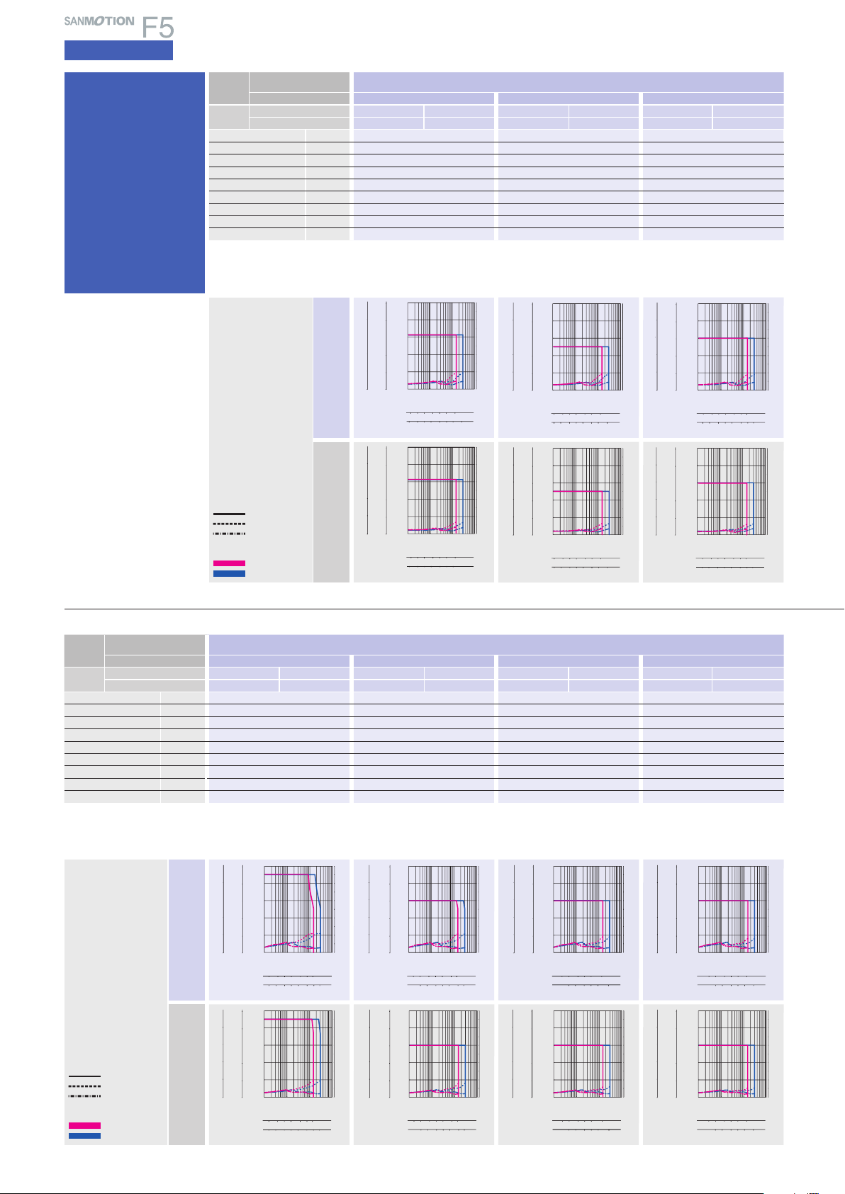
17
AC input
Specifications
5-phase STEPPING SYSTEMS
12 5102060
12 5102060
0
0
4
8
12
16
20
0.1 110 100
0
1
2
3
4
5
6
7
8
9
10
200
160
120
80
40
160
120
80
40
0
Torque( kgf・cm )
Torque( lb-in )
Torque(N・m )
Source current (A)
Pulse rate (kpulse/s)
1-division
2-division
Number of rotations (min
-1
)
12 5102060
12 5102060
0
0
4
8
12
16
20
0.1 110 100
0
1
2
3
4
5
6
7
8
9
10
200
160
120
80
40
160
120
80
40
0
Torque( kgf・cm )
Torque( lb-in )
Torque(N・m )
Source current (A)
Pulse rate (kpulse/s)
1-division
2-division
Number of rotations (min
-1
)
12 5102050
12 5102050
0
0
4
8
12
16
20
0.1 110 100
0
1
2
3
4
5
6
7
8
9
10
200
160
120
80
40
160
120
80
40
0
Torque( kgf・cm )
Torque( lb-in )
Torque(N・m )
Source current (A)
Pulse rate (kpulse/s)
1-division
2-division
Number of rotations (min
-1
)
12 5102050
12 5102050
0
0
4
8
12
16
20
0.1 110 100
0
1
2
3
4
5
6
7
8
9
10
200
160
120
80
40
160
120
80
40
0
Torque( kgf・cm )
Torque( lb-in )
Torque(N・m )
Source current (A)
Pulse rate (kpulse/s)
1-division
2-division
Number of rotations (min
-1
)
AC100V
AC200V
Allowable torque
Source current (load applied)
Source current (no load)
1-division
2-division
Operating current:
0.75A/phase
12 5102050 100
2510 20 50 100 180
180
0
0
2
4
6
8
10
0.1 110 100
0
1
2
3
4
5
6
7
8
9
10
100
80
60
40
20
80
60
40
20
0
Torque( kgf・cm )
Torque( lb-in )
Torque(N・m )
Source current (A)
Pulse rate (kpulse/s)
1-division
2-division
Number of rotations (min
-1
)
12 5102050 100
2510 20 50 100 180
180
0
0
2
4
6
8
10
0.1 110 100
0
1
2
3
4
5
6
7
8
9
10
100
80
60
40
20
80
60
40
20
0
Torque( kgf・cm )
Torque( lb-in )
Torque(N・m )
Source current (A)
Pulse rate (kpulse/s)
1-division
2-division
Number of rotations (min
-1
)
12 510205090
12 510205090
0
0
4
8
12
16
20
0.1 110 100
0
1
2
3
4
5
6
7
8
9
10
200
160
120
80
40
160
120
80
40
0
Torque( kgf・cm )
Torque( lb-in )
Torque(N・m )
Source current (A)
Pulse rate (kpulse/s)
1-division
2-division
Number of rotations (min
-1
)
12 510205090
12 510205090
0
0
4
8
12
16
20
0.11 10 100
0
1
2
3
4
5
6
7
8
9
10
200
160
120
80
40
160
120
80
40
0
Torque( kgf・cm )
Torque( lb-in )
Torque(N・m )
Source current (A)
Pulse rate (kpulse/s)
1-division
2-division
Number of rotations (min
-1
)
Size
Motor flange size
φ
86
mm
(
φ
3.39
inch
)
Motor + gear length
127.3mm
(
5.01inch
)
127.3mm
(
5.01inch
)
127.3mm
(
5.01inch
)
127.3mm
(
5.01inch
)
Set par t
number
Single shaft
FSF851S-CX10 FPF851S- CX10 FSF851S- CX20 FPF851S-CX 20 FSF851S-CX30 FPF851S-CX30 FSF851S-CX36 FPF851S-CX36
Double shaft
FSF851D-CX10 FPF8 51D-CX10 FSF851D-CX20 FPF851D-CX20 FSF851D-CX30 FPF851D-CX30 FSF851D-CX36 FPF851D-CX36
Allowable torque N
・
m
(
oz
・
in
)
9
(
1274.5
)
12
(
1699.3
)
12
(
1699.3
)
12
(
1699.3
)
Rotor iner tia
×10
-4
kg・m
2
(oz・in
2
)
1.45
(
7.93
)
1.45
(
7.93
)
1.45
(
7.93
)
1.45
(
7.93
)
Basic step angle 0.072 0.036 0.024 0.02
Gear rati o 1
:
10 1
:
20 1
:
30 1
:
36
Backlash DEG 0.22 0.15 0.15 0.15
Allowable speed min
-1
180 90 60 50
Mass
(
Weight
)
kg
(
lbs
)
2.7
(
5.94
)
2.7
(
5.94
)
2.7
(
5.94
)
2.7
(
5.94
)
Allowable thrust load N
(
lbs
)
60
(
13.5
)
60
(
13.5
)
60
(
13.5
)
60
(
13.5
)
Allowable
radial load
(
Note 1
)
N
(
lbs
)
300
(
67.5
)
300
(
67.5
)
300
(
67.5
)
300
(
67.5
)
Directio ns of motor rotat ion and gear o utput shaf t are the same fo r models wit h reductio n ratio 1 : 3.6 an d 1:7.2, opp osite for redu ction rati o 1 : 10, 1 : 20 and 1 : 30.
(
Note1
)
When loa d is applied at 1/ 3 length from output s haft edge .
5102050 10021
10 20 50 100 25052
250
0
0
1
2
3
4
5
0.1 110 100
0
1
2
3
4
5
6
7
8
9
10
50
40
30
20
10
40
30
20
10
0
Torque( kgf・cm )
Torque( lb-in )
Torque(N・m )
Source current (A)
Pulse rate (kpulse/s)
1-division
2-division
Number of rotations (min
-1
)
5102050 10021
10 20 50 100 25052
250
0
0
1
2
3
4
5
0.1 110 100
0
1
2
3
4
5
6
7
8
9
10
50
40
30
20
10
40
30
20
10
0
Torque( kgf・cm )
Torque( lb-in )
Torque(N・m )
Source current (A)
Pulse rate (kpulse/s)
1-division
2-division
Number of rotations (min
-1
)
2510 20 50 100 180
12 5102050 100
180
0
0
1
2
3
4
5
0.11 10 100
0
1
2
3
4
5
6
7
8
9
10
50
40
30
20
10
40
30
20
10
0
Torque( kgf・cm )
Torque( lb-in )
Torque(N・m )
Source current (A)
Pulse rate (kpulse/s)
1-division
2-division
Number of rotations (min
-1
)
2510 20 50 100 180
12 5102050 100
180
0
0
1
2
3
4
5
0.1 110 100
0
1
2
3
4
5
6
7
8
9
10
50
40
30
20
10
40
30
20
10
0
Torque( kgf・cm )
Torque( lb-in )
Torque(N・m )
Source current (A)
Pulse rate (kpulse/s)
1-division
2-division
Number of rotations (min
-1
)
5102050 100 200 500
2510 20 50 100 200
0
0
0.4
0.8
1.2
1.6
2.0
0.1 110 100
0
1
2
3
4
5
6
7
8
9
10
20
16
12
8
4
16
12
8
4
0
Torque( kgf・cm )
Torque( lb-in )
Torque(N・m )
Source current (A)
Pulse rate (kpulse/s)
Number of rotations (min
-1
)
1-division
2-division
500
5102050 100 200 500
2510 20 50 100 200
0
0
0.4
0.8
1.2
1.6
2.0
0.1 110 100
0
1
2
3
4
5
6
7
8
9
10
20
16
12
8
4
16
12
8
4
0
Torque( kgf・cm )
Torque( lb-in )
Torque(N・m )
Source current (A)
Pulse rate (kpulse/s)
Number of rotations (min
-1
)
1-division
2-division
500
Size
Motor flange size
□
60
mm
(
□
2.36
inch
)
Motor + gear length
92mm
(
3.62inch
)
92mm
(
3.62inch
)
92mm
(
3.62inch
)
Set par t
number
Single shaft
FSF781S-CX3.6 FPF781S-CX3.6 FSF781S- CX7.2 FPF781S-CX7.2 FSF781S-CX10 FPF781S-CX10
Double shaft
FSF781D-CX3.6 FPF781D-CX3.6 FSF781D-CX7.2 FPF781D-CX7.2 FSF781D-CX10 FPF781D-CX10
Allowable torque N
・
m
(
oz
・
in
)
1.25
(
177.0
)
2.5
(
354.0
)
3
(
424.8
)
Rotor iner tia
×10
-4
kg・m
2
(oz・in
2
)
0.275
(
1.5
)
0.275
(
1.5
)
0.275
(
1.5
)
Basic step angle 0.2 0.1 0.072
Gear rati o 1
:
3.6 1
:
7.2 1
:
10
Backlash DEG 0.55 0.25 0.25
Allowable speed min
-1
500 250 180
Mass
(
Weight
)
kg
(
lbs
)
0.97
(
2.13
)
0.97
(
2.13
)
0.97
(
2.13
)
Allowable thrust load N
(
lbs
)
30
(
6.75
)
30
(
6.75
)
30
(
6.75
)
Allowable
radial load
(
Note 1
)
N
(
lbs
)
100
(
22.5
)
100
(
22.5
)
100
(
22.5
)
Directio ns of motor rotat ion and gear ou tput shaf t are the same for m odels with r eduction r atio 1 : 3.6 and 1:7.2, oppo site for reduc tion ratio 1 : 10,
1 : 20 and 1 : 30 .
(
Note1
)
When loa d is applied at 1/ 3 length from output s haft edge .
AC100V
AC200V
Allowable torque
Source current (load applied)
Source current (no load)
1-division
2-division
Operating current:
0.75A/phase
Low-backlash
gear model
F series driver +
F series motor with low-
backlash gear
The data a re measured und er the drive c ondition of o ur company. Th e drive
torque may ver y depending on the acc uracy of cust omer-side e quipment.
The data a re measured und er the drive c ondition of o ur company. Th e drive torque m ay very dep ending on th e accuracy o f customer-s ide equipm ent.
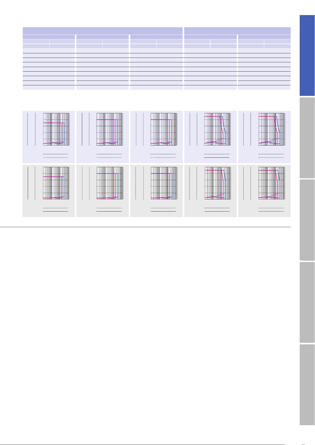
18
AC inputInput / Output signal standardDC inputStepping motorDimensions
5102050 100 200 500
2510 20 50 100 200
500
0
0
1
2
3
4
5
0.11 10 100
0
1
2
3
4
5
6
7
8
9
10
50
40
30
20
10
40
30
20
10
0
Torque( kgf・cm )
Torque( lb-in )
Torque(N・m )
Source current (A)
Pulse rate (kpulse/s)
1-division
2-division
Number of rotations (min
-1
)
5102050 100 200 500
2510 20 50 100 200
500
0
0
1
2
3
4
5
0.1 110 100
0
1
2
3
4
5
6
7
8
9
10
50
40
30
20
10
40
30
20
10
0
Torque( kgf・cm )
Torque( lb-in )
Torque(N・m )
Source current (A)
Pulse rate (kpulse/s)
1-division
2-division
Number of rotations (min
-1
)
12 5102050 100
100 250
2510 20 50
250
0
0.1 110 100
0
1
2
3
4
5
6
7
8
9
10
100
80
60
40
20
80
60
40
20
0 0
10
8
6
4
2
Torque( kgf・cm )
Torque( lb-in )
Torque(N・m )
Source current (A)
Pulse rate (kpulse/s)
1-division
2-division
Number of rotations (min
-1
)
12 5102050 100
100 250
2510 20 50
250
0
0.1 110 100
0
1
2
3
4
5
6
7
8
9
10
100
80
60
40
20
80
60
40
20
0 0
10
8
6
4
2
Torque( kgf・cm )
Torque( lb-in )
Torque(N・m )
Source current (A)
Pulse rate (kpulse/s)
1-division
2-division
Number of rotations (min
-1
)
12 5102060
12 5102060
0
0
1
2
3
4
5
0.11 10 100
0
1
2
3
4
5
6
7
8
9
10
50
40
30
20
10
40
30
20
10
0
Torque( kgf・cm )
Torque( lb-in )
Torque(N・m )
Source current (A)
Pulse rate (kpulse/s)
1-division
2-division
Number of rotations (min
-1
)
12 5102060
12 5102060
0
0
1
2
3
4
5
0.1 110 100
0
1
2
3
4
5
6
7
8
9
10
50
40
30
20
10
40
30
20
10
0
Torque( kgf・cm )
Torque( lb-in )
Torque(N・m )
Source current (A)
Pulse rate (kpulse/s)
1-division
2-division
Number of rotations (min
-1
)
12 5102050
12 5102050
0
0
1
2
3
4
5
0.1 110 100
0
1
2
3
4
5
6
7
8
9
10
50
40
30
20
10
40
30
20
10
0
Torque( kgf・cm )
Torque( lb-in )
Torque(N・m )
Source current (A)
Pulse rate (kpulse/s)
1-division
2-division
Number of rotations (min
-1
)
12 5102050
12 5102050
0
0
1
2
3
4
5
0.1 110 100
0
1
2
3
4
5
6
7
8
9
10
50
40
30
20
10
40
30
20
10
0
Torque( kgf・cm )
Torque( lb-in )
Torque(N・m )
Source current (A)
Pulse rate (kpulse/s)
1-division
2-division
Number of rotations (min
-1
)
12 510205090
12 510205090
0
0
1
2
3
4
5
0.1 110 100
0
1
2
3
4
5
6
7
8
9
10
50
40
30
20
10
40
30
20
10
0
Torque( kgf・cm )
Torque( lb-in )
Torque(N・m )
Source current (A)
Pulse rate (kpulse/s)
1-division
2-division
Number of rotations (min
-1
)
12 510205090
12 510205090
0
0
1
2
3
4
5
0.1 110 100
0
1
2
3
4
5
6
7
8
9
10
50
40
30
20
10
40
30
20
10
0
Torque( kgf・cm )
Torque( lb-in )
Torque(N・m )
Source current (A)
Pulse rate (kpulse/s)
1-division
2-division
Number of rotations (min
-1
)
□
60
mm
(
□
2.36
inch
)
φ
86
mm
(
φ
3.39
inch
)
92mm
(
3.62inch
)
92mm
(
3.62inch
)
92mm
(
3.62inch
)
127.3mm
(
5.01inch
)
127.3mm
(
5.01inch
)
FSF781S-CX20 FPF781S-CX20 FSF781S-CX30 FPF781S-CX30 FSF781S-CX36 FPF781S-CX36 FSF851S-CX3.6 FPF851S-CX3.6 FSF8 51S-CX7.2 FPF851S-CX7.2
FSF781D-CX20 FPF781D- CX20 FSF781D-CX30 FPF781D- CX30 FSF781D-CX36 FPF781D-CX36 FSF8 51D-CX3.6 FPF851D- CX3.6 FSF851D-CX7.2 FPF851D-CX7.2
3.5
(
495.6
)
4
(
566.4
)
4
(
566.4
)
4.5
(
637.2
)
9
(
1274.5
)
0.275
(
1.5
)
0.275
(
1.5
)
0.275
(
1.5
)
1.45
(
7.93
)
1.45
(
7.93
)
0.036 0.024 0.02 0.2 0.1
1
:
20 1
:
30 1
:
36 1
:
3.6 1
:
7.2
0.17 0.17 0.17 0.35 0.22
90 60 50 500 250
0.97
(
2.13
)
0.97
(
2.13
)
0.97
(
2.13
)
2.7
(
5.94
)
2.7
(
5.94
)
30
(
6.75
)
30
(
6.75
)
30
(
6.75
)
60
(
13.5
)
60
(
13.5
)
100
(
22.5
)
100
(
22.5
)
100
(
22.5
)
300
(
67.5
)
300
(
67.5
)
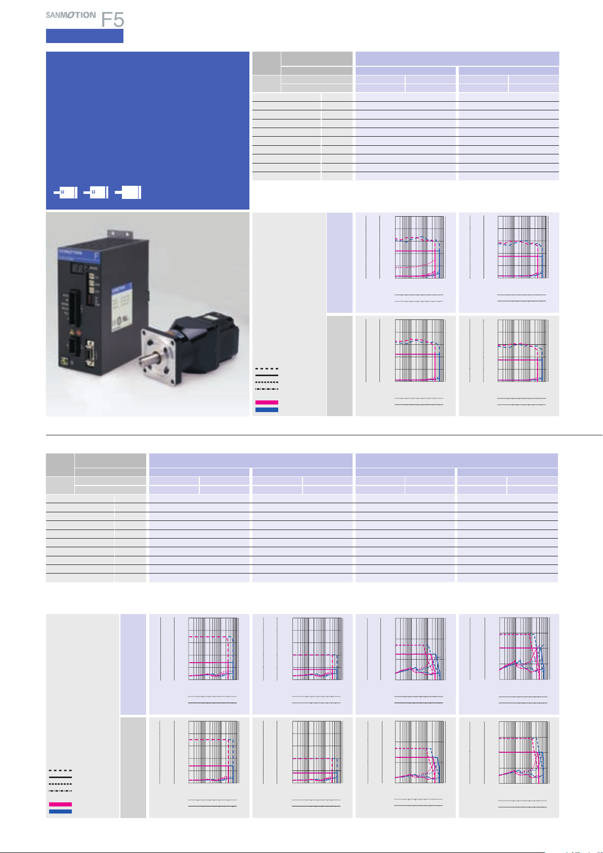
19
AC input
Specifications
5-phase STEPPING SYSTEMS
12
5
10 20 35
12 5102035
0
0.1 110 100
0
1
2
3
480
20
40
60
800
200
400
600
0
200
400
600
0
Torque( kgf・cm )
Torque( lb-in )
Torque(N・m )
Source current (A)
Pulse rate (kpulse/s)
Number of rotations (min
-1
)
1-division
2-division
12
5
10 20 35
12 5102035
0
0.1 110 100
0
1
2
3
4
40
60
80
20
400
600
800
200
400
600
200
0 0
Torque( kgf・cm )
Torque( lb-in )
Torque(N・m )
Source current (A)
Pulse rate (kpulse/s)
Number of rotations (min
-1
)
1-division
2-division
Size
Motor flange size
□
60
mm
(
□
2.36
inch
)
φ
86
mm
(
φ
3.39
inch
)
Motor + gear length
113.5mm
(
4.47inch
)
113.5mm
(
4.47inch
)
113.5mm
(
4.47inch
)
113.5mm
(
4.47inch
)
Set par t
number
Single shaft
FSF781S-HX50 FPF781S-HX50 FSF781S-HX100 FPF781S-HX100 FSF851S- HX50 FPF851S-HX50 FSF851S-HX100 FPF851S- HX100
Double shaft
FSF781D-HX50 FPF781D- HX50 FSF781D-HX100 FPF781D-HX100 FSF851D-HX50 FPF851D-HX50 FSF851D-HX100 FPF851D-HX100
Allowable torque N
・
m
(
oz
・
in
)
5.5
(
778.8
)
8
(
1132.9
)
25
(
3540.2
)
40
(
5664.3
)
Momentary allow able torque
N
・
m
(
oz
・
in
)
14
(
1982.6
)
20
(
2832.2
)
34
(
4814.8
)
59
(
8355.1
)
Rotor iner tia
×10
-4
kg・m
2
(oz・in
2
)
0.31
(
1.695
)
0.31
(
1.695
)
1.65
(
9.021
)
1.65
(
9.021
)
Basic step angle 0.0144 0.0072 0.0144 0.0072
Gear rati o 1
:
50 1
:
100 1
:
50 1
:
100
Lost motion Minute
0.4 to 3
±
0.028N
・
m
(
3.965oz
・
in
)
0.4 to 1.5
±
0.4N
・
m
(
56.6 45oz
・
in
)
0.4 to 3
±
1N
・
m
(
141.612oz
・
in
)
0.4 to 3
±
1.2N
・
m
(
169.934oz
・
in
)
Allowable speed min
-1
70 35 70 35
Mass
(
Weight
)
kg
(
lbs
)
1.2
(
2.64
)
1.2
(
2.64
)
3.3
(
7.26
)
3.3
(
7.26
)
Allowable thrust load N
(
lbs
)
400
(
90
)
400
(
90
)
1400
(
315
)
1400
(
315
)
Allowable
radial load
(
Note 1
)
N
(
lbs
)
360
(
81
)
360
(
81
)
1350
(
303.5
)
1380
(
310.5
)
AC100V
AC200V
AC100V
AC200V
Harmonic gear
model
F series driver +
F series motor with harmonic gear
Size
Motor flange size
□
42
mm
(
□
1.65
inch
)
Motor + gear length
73.5mm
(
2.89inch
)
73.5mm
(
2.89inch
)
Set par t
number
Single shaft
FSF551S-HX30 FPF551S-HX30 FSF551S-HX50 FPF551S-HX50
Double shaft
FSF551D-HX30 FPF551D-HX30 FSF551D-HX50 FPF551D-HX50
Allowable torque N
・
m
(
oz
・
in
)
2.2
(
311.5
)
3.5
(
495.6
)
Momentary allow able torque
N
・
m
(
oz
・
in
)
4.5
(
637.3
)
8.3
(
1175.4
)
Rotor iner tia
×10
-4
kg・m
2
(oz・in
2
)
0.042
(
0.23
)
0.042
(
0.23
)
Basic step angle 0.024 0.0144
Gear ratio 1
:30 1
:
50
Hysteresis loss Minute 3.6 2.4
Allowable speed min
-1
116 70
Mass
(
Weight
)
kg
(
lbs
)
0.42
(
0.92
)
0.42
(
0.92
)
Allowable thrust load N
(
lbs
)
1150
(
258.75
)
1150
(
258.75
)
Allowable
radial load
(
Note 1
)
N
(
lbs
)
209
(
46.98
)
209
(
46.98
)
Directio ns of gear out put shaft are t he opposi te.
(
Note1
)
When loa d is applied at 1/ 3 length from output s haft edge .
Directio ns of gear out put shaft are t he opposi te.
(
Note1
)
When loa d is applied at 1/ 3 length from output sh aft edge .
42
60
86
φ
(
φ
3.39inch)(
□
2.35inch)(
□
1.65inch)
Motor flange size
Momentary allowable torque
Allowable torque
Source current (load applied)
Source current (no load)
1-division
2-division
Operating current:
0.75A/phase
Momentary allowable torque
Allowable torque
Source current (load applied)
Source current (no load)
1-division
2-division
Operating current:
0.75A/phase
The data a re measured und er the drive c ondition of o ur company. Th e drive
torque may ver y depending on the acc uracy of cust omer-side e quipment.
1 2 5 10 20 50 116
1 2 5 10 20 50 116
0
0.1 110 100
0
1
2
3
4
5
6
7
8
9
10
50
40
30
20
10
40
30
20
10
0 0
5
4
3
2
1
Torque( kgf・cm )
Torque( lb-in )
Torque(N・m )
Source current (A)
Pulse rate (kpulse/s)
Number of rotations (min
-1
)
1-division
2-division
1 2 5 10 20 50 116
1 2 5 10 20 50 116
0
0.1 110 100
0
1
2
3
4
5
6
7
8
9
10
50
40
30
20
10
40
30
20
10
0 0
5
4
3
2
1
Torque( kgf・cm )
Torque( lb-in )
Torque(N・m )
Source current (A)
Pulse rate (kpulse/s)
Number of rotations (min
-1
)
1-division
2-division
12 5102070
12 5102070
0
0
2
4
6
8
10
0.11 10 100
0
1
2
3
4
5
6
7
8
9
10
100
80
60
40
20
80
60
40
20
0
Torque( kgf・cm )
Torque( lb-in )
Torque(N・m )
Source current (A)
Pulse rate (kpulse/s)
Number of rotations (min
-1
)
1-division
2-division
12 5102070
12 5102070
0
0
2
4
6
8
10
0.1 110 100
0
1
2
3
4
5
6
7
8
9
10
100
80
60
40
20
80
60
40
20
0
Torque( kgf・cm )
Torque( lb-in )
Torque(N・m )
Source current (A)
Pulse rate (kpulse/s)
1-division
2-division
Number of rotations (min
-1
)
510201
2
70
510201
2
70
0
0.11 10 100
0
1
2
3
4
5
6
7
8
9
10
200
160
120
80
40
160
120
80
40
0 0
20
16
12
8
4
Torque( kgf・cm )
Torque( lb-in )
Torque(N・m )
Source current (A)
Pulse rate (kpulse/s)
Number of rotations (min
-1
)
1-division
2-division
510201
2
70
510201
2
70
0
0.1 110 100
0
1
2
3
4
5
6
7
8
9
10
200
160
120
80
40
160
120
80
40
0 0
20
16
12
8
4
Torque( kgf・cm )
Torque( lb-in )
Torque(N・m )
Source current (A)
Pulse rate (kpulse/s)
Number of rotations (min
-1
)
1-division
2-division
1
51020
2
35
510201
2
35
0
0.1 110 100
0
1
2
3
4
5
6
7
8
9
10
500
400
300
200
100
400
300
200
100
0 0
50
40
30
20
10
Torque( kgf・cm )
Torque( lb-in )
Torque(N・m )
Source current (A)
Pulse rate (kpulse/s)
Number of rotations (min
-1
)
1-division
2-division
1
51020
2
35
510201
2
35
0
0.1 110 100
0
1
2
3
4
5
6
7
8
9
10
500
400
300
200
100
400
300
200
100
0 0
50
40
30
20
10
Torque( kgf・cm )
Torque( lb-in )
Torque(N・m )
Source current (A)
Pulse rate (kpulse/s)
Number of rotations (min
-1
)
1-division
2-division
1
2
5102070
1
2
5102070
0
0.1 110 100
0
1
2
3
4
5
660
40
20
Torque( kgf・cm )
Torque( lb-in )
Torque(N・m )
Source current (A)
Pulse rate (kpulse/s)
Number of rotations (min
-1
)
1-division
2-division
0
600
400
200
0
400
200
1
2
5102070
1
2
5102070
0
0.1 110 100
0
1
2
3
4
5
660
40
20
600
400
200
0
Torque( kgf・cm )
Torque( lb-in )
Torque(N・m )
Source current (A)
Pulse rate (kpulse/s)
Number of rotations (min
-1
)
1-division
2-division
400
200
0
The data a re measured und er the drive c ondition of o ur company. Th e drive torque m ay very dep ending on th e accuracy o f customer-s ide equipm ent.
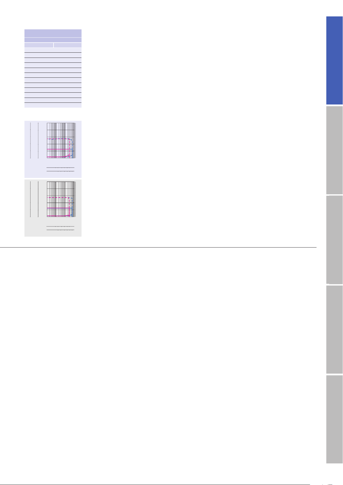
20
AC inputInput / Output signal standardDC inputStepping motorDimensions
12 5102035
12 5102035
0
0
4
8
12
16
20
0.1 110 100
0
1
2
3
4
5
6
7
8
9
10
200
160
120
80
40
160
120
80
40
0
Torque( kgf・cm )
Torque( lb-in )
Torque(N・m )
Source current (A)
Pulse rate (kpulse/s)
Number of rotations (min
-1
)
1-division
2-division
12 5102035
12 5102035
0
0
4
8
12
16
20
0.1 110 100
0
1
2
3
4
5
6
7
8
9
10
200
160
120
80
40
160
120
80
40
0
Torque( kgf・cm )
Torque( lb-in )
Torque(N・m )
Source current (A)
Pulse rate (kpulse/s)
Number of rotations (min
-1
)
1-division
2-division
□
42
mm
(
□
1.65
inch
)
73.5mm
(
2.89inch
)
FSF551S-HX100 FPF551S-HX100
FSF551D-HX100
FPF551D-HX100
5
(
708.1
)
11
(
1557.7
)
0.042
(
0.23
)
0.0072
1
:
100
2.4
35
0.42
(
0.92
)
1150
(
258.75
)
209
(
46.98
)
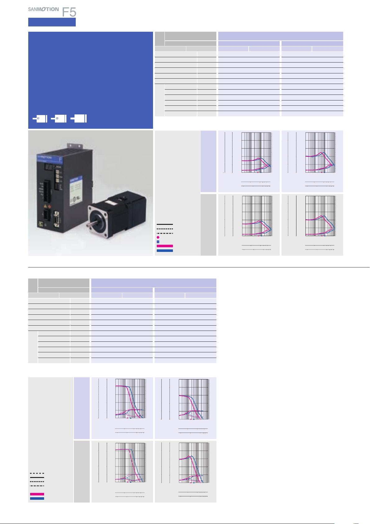
21
AC input
Specifications
5-phase STEPPING SYSTEMS
0
0
1
2
3
4
5
0.1 110 100
0
1
2
3
4
5
6
7
8
9
10
50
40
30
20
10
40
30
20
10
0
Torque( kgf・cm )
Torque( lb-in )
Torque(N・m )
Source current (A)
Pulse rate (kpulse/s)
100 1000 2000 3000 5000
Number of rotations (min
-1
)
1-division
2-division
10 100 1000 2000 3000 5000
Torque(N・m )
Source current (A)
Pulse rate (kpulse/s)
1-division
2-division
Number of rotations (min
-1
)
0
1
2
3
4
5
0
1
2
3
4
5
6
7
8
9
10
0.1 110 100
100 1000 2000 30005000
10 100 1000 200030005000
0
50
40
30
20
10
40
30
20
10
Torque( kgf・cm )
0
Torque( lb-in )
100 1000 2000 3000 5000
100 100 1000 20003000 5000
0
0
2
4
6
8
10
0.1 110 100
0
1
2
3
4
5
6
7
8
9
10
100
80
60
40
20
80
60
40
20
0
Torque( kgf・cm )
Torque( lb-in )
Torque(N・m )
Source current (A)
Pulse rate (kpulse/s)
1-division
2-division
Number of rotations (min
-1
)
100 1000 2000 3000 5000
100 100 1000 20003000 5000
0
0
2
4
6
8
10
0.1 110 100
0
1
2
3
4
5
6
7
8
9
10
100
80
60
40
20
80
60
40
20
0
Torque( kgf・cm )
Torque( lb-in )
Torque(N・m )
Source current (A)
Pulse rate (kpulse/s)
1-division
2-division
Number of rotations (min
-1
)
AC100V
AC200V
Momentary allowable torque
Allowable torque
Source current (load applied)
Source current (no load)
1-division
2-division
Operating current:
0.75A/phase
Size
Motor flange size
φ
86
mm
(
φ
3.39
inch
)
Motor + brake length
146.8mm
(
5.78mm
)
180.4mm
(
7.10mm
)
Set par t number
Single shaft
FSF852S-XB FPF852S-XB FSF853S -XB FPF853S-XB
Holding torque N
・
m
(
oz
・
in
)
4.02
(
569. 3
)
6.17
(
873.7
)
Rotor iner tia
×10
-4
kg・m
2
(oz・in
2
)
3.69
(
20.175
)
5.19
(
28.376
)
Mass
(
Weight
)
kg
(
lbs
)
4.5
(
9.9
)
5.5
(
12.1
)
Allowable thrust load N
(
lbs
)
60
(
13.5
)
60
(
13.5
)
Allowable radial l oad
(
Note 1
)
N
(
lbs
)
220
(
49.5
)
220
(
49.5
)
Brake type No excitation actuating t ype No excitation actuating type
Power supply input
V DC24V
±
5% DC24V
±
5%
Excitation current
A 0.42 0.42
Power consumption
W 10 10
Static fiction torque
N
・
m
(
oz
・
in
)
4
(
566.45
)
4
(
566.45
)
Brake operating time
ms 50 50
Brake releas e time
ms 20 20
Electromagnetic
brake
100 1000 2000 3000 5000
10 100 1000 2000 3000 5000
0
0.1
0.2
0.3
0.4
0.5
0
1
2
3
4
1
2
3
4
5
0
0.11 10 100
0
1
2
3
4
5
6
7
8
9
10
Torque( kgf・cm )
Torque( lb-in )
Torque(N・m )
Source current (A)
Pulse rate (kpulse/s)
1-division
2-division
Number of rotations (min
-1
)
100 1000 2000 3000 5000
10 100 1000 2000 3000 5000
0
0.1
0.2
0.3
0.4
0.5
0
1
2
3
4
1
2
3
4
5
0
0.1 110 100
0
1
2
3
4
5
6
7
8
9
10
Torque( kgf・cm )
Torque( lb-in )
Torque(N・m )
Source current (A)
Pulse rate (kpulse/s)
1-division
2-division
Number of rotations (min
-1
)
100 1000 2000 3000 5000
10 100 1000 2000 3000 5000
0
0.1
0.2
0.3
0.4
0.5
0
1
2
3
4
1
2
3
4
5
0
0.1 110 100
0
1
2
3
4
5
6
7
8
9
10
Torque( kgf・cm )
Torque( lb-in )
Torque(N・m )
Source current (A)
Pulse rate (kpulse/s)
1-division
2-division
Number of rotations (min
-1
)
100 1000 2000 3000 5000
10 100 1000 2000 3000 5000
0
0.1
0.2
0.3
0.4
0.5
0
1
2
3
4
1
2
3
4
5
0
0.1 110 100
0
1
2
3
4
5
6
7
8
9
10
Torque( kgf・cm )
Torque( lb-in )
Torque(N・m )
Source current (A)
Pulse rate (kpulse/s)
1-division
2-division
Number of rotations (min
-1
)
AC100V
AC200V
Electromagnetic
brake model
F series driver + F series motor with
electromagnetic brake
Size
Motor flange size
□
42
mm
(
□
1.65
inch
)
Motor + brake length
64.5mm
(
2.54inch
)
70.5mm
(
2.78inch
)
Set par t number
Single shaft
FSF551S-XB FPF551S-XB FSF552S-XB FPF552S-XB
Holding torque N
・
m
(
oz
・
in
)
0.13
(
8.4
)
0.18
(
25.49
)
Rotor iner tia
×10
-4
kg・m
2
(oz・in
2
)
0.04 5
(
0.246
)
0.068
(
0.372
)
Mass
(
Weight
)
kg
(
lbs
)
0.38
(
0.84
)
0.43
(
0.95
)
Allowable thrust load N
(
lbs
)
10
(
2.25
)
10
(
2.25
)
Allowable radial l oad
(
Note 1
)
N
(
lbs
)
35
(
8.75
)
35
(
8.75
)
Brake type No excitation actuating type No excitation ac tuating type
Power supply input
V DC24V
±
5% DC24V
±
5%
Excitation current
A 0.08 0.08
Power consumption
W 2 2
Static fiction torque
N
・
m
(
oz
・
in
)
0.22
(
31.15
)
0.22
(
31.15
)
Brake operating time
ms 30 30
Brake releas e time
ms 20 20
(
Note1
)
When loa d is applied at 1/ 3 length from output s haft edge .
42
60
86
106
φ
φ
(
φ
4.17inch)
(
φ
3.39inch
)
(
□
2.35inch)(
□
1.65inch)
Motor flange size
Electromagnetic
brake
Pull-out torque
Source current (load applied)
Source current (no load)
Fs:
Maximum self-start
frequency when not loaded
1-division
2-division
Operating current:
0.75A/phase
1-division fs
2-division fs
The data a re measured und er the drive c ondition of o ur company. Th e drive
torque may ver y depending on the acc uracy of cust omer-side e quipment.
The data a re measured und er the drive c ondition of o ur company. Th e drive
torque may ver y depending on the acc uracy of cust omer-side e quipment.
(
Note1
)
When loa d is applied at 1/ 3 length from output s haft edge .
Loading...