


S15
11.19
284.16
2.25
57.15
20.83
529.20
2.25
57.15
8.00
203.20
4.00
101.60
2.18
55.39
1 1/2 NPT DISCHARGE PORT
20.41
518.41
4.68
118.87
4.68
118.87
11.19
284.16
2.00
50.80
22.41
569.21
12.87
326.90
DISCHARGE PORT
1 1/2" RF 150# ANSI
5/8" DIA,(4) HOLES EQ. SPC'D
ON 3.88" DIA. BOLT CIRCLE
SERVICE & OPERATING MANUAL
Original Instructions
Certied Quality
Model S15
Metallic
Design Level 1
1: PUMP SPECS2: INSTAL & OP3: EXP VIEW4: AIR END5: WET END6: OPTIONAL7: WARRANTY
Quality System
ISO 9001 Certied
Environmental Management System
ISO 14001 Certied
Warren Rupp, Inc.
A Unit of IDEX Corporation
800 N. Main St.,
Manseld, Ohio 44902 USA
Telephone 419.524.8388
Fax 419.522.7867
SANDPIPERPUMP.COM
© Copyright 2014 Warren Rupp, Inc.
All rights reserved
sa nd pi pe rp um p. co m
Safety Information
IMPORTANT
Read the safety warnings and instructions in this manual
before pump installation and start-up. Failure to comply with
the recommendations stated in this manual could damage the
pump and void factory warranty.
When the pump is used for materials that tend to settle out
or solidify, the pump should be ushed after each use to
prevent damage. In freezing temperatures the pump should be
completely drained between uses.
CAUTION
Before pump operation, inspect all fasteners for loosening
caused by gasket creep. Retighten loose fasteners to prevent
leakage. Follow recommended torques stated in this manual.
Nonmetallic pumps and plastic components are not UV
stabilized. Ultraviolet radiation can damage these parts and
negatively affect material properties. Do not expose to UV light
for extended periods of time.
WARNING
Pump not designed, tested or certied to be powered by
compressed natural gas. Powering the pump with natural
gas will void the warranty.
WARNING
When used for toxic or aggressive uids, the pump should
always be ushed clean prior to disassembly.
Before maintenance or repair, shut off the compressed air line,
bleed the pressure, and disconnect the air line from the pump.
Be certain that approved eye protection and protective clothing
are worn at all times. Failure to follow these recommendations
may result in serious injury or death.
Airborne particles and loud noise hazards. Wear eye and ear
protection.
In the event of diaphragm rupture, pumped material may enter
the air end of the pump, and be discharged into the atmosphere.
If pumping a product that is hazardous or toxic, the air exhaust
must be piped to an appropriate area for safe containment.
Take action to prevent static sparking. Fire or explosion can
result, especially when handling ammable liquids. The pump,
piping, valves, containers and other miscellaneous equipment
must be properly grounded.
This pump is pressurized internally with air pressure during
operation. Make certain that all fasteners are in good condition
and are reinstalled properly during reassembly.
kg
Use safe practices when lifting
Grounding the Pump
To be fully groundable, the pumps must be ATEX Compliant. Refer to the nomenclature page for ordering information.
Optional 8 foot long (244 centimeters) Ground Strap is available for easy ground connection.
To reduce the risk of static electrical sparking, this pump must be grounded. Check the local
electrical code for detailed grounding instruction and the type of equipment required.
Refer to nomenclature page for ordering information.
WARNING
Take action to prevent static sparking.
Fire or explosion can result, especially
when handling ammable liquids. The
pump, piping, valves, containers or
other miscellaneous equipment must
be grounded.
sa n d pip er pu mp .c om
s15mdl1sm-rev0614

Table of Contents
SECTION 1: PUMP SPECIFICATIONS ................1
• Explanation of Nomenclature
• Performance
• Materials
• Dimensional Drawings
SECTION 2: INSTALLATION & OPERATION ......5
• Principle of Pump Operation
• Recommended Installation Guide
• Troubleshooting Guide
SECTION 3: EXPLODED VIEW ...........................8
• Composite Repair Parts Drawing
• Composite Repair Parts List
• Material Codes
1: PUMP SPECS2: INSTAL & OP3: EXP VIEW4: AIR END5: WET END6: OPTIONAL7: WARRANTY
SECTION 4: AIR END .......................................11
• Air Distribution Valve Assembly
• Air Valve with Stroke Indicator Assembly
• Pilot Valve Assembly
• Intermediate Assembly
SECTION 5: WET END .....................................17
• Diaphragm Drawings
• Diaphragm Servicing
SECTION 6: OPTIONAL CONFIGURATIONS ....19
• Solenoid Shifted Air Valve
SECTION 7: WARRANTY & CERTIFICATES ....20
• Warranty
• CE Declaration of Conformity - Machinery
• ATEX Declaration of Conformity
• ATEX Summary of Markings
sa n d pip er pu mp .c om
s15mdl1sm-rev0614
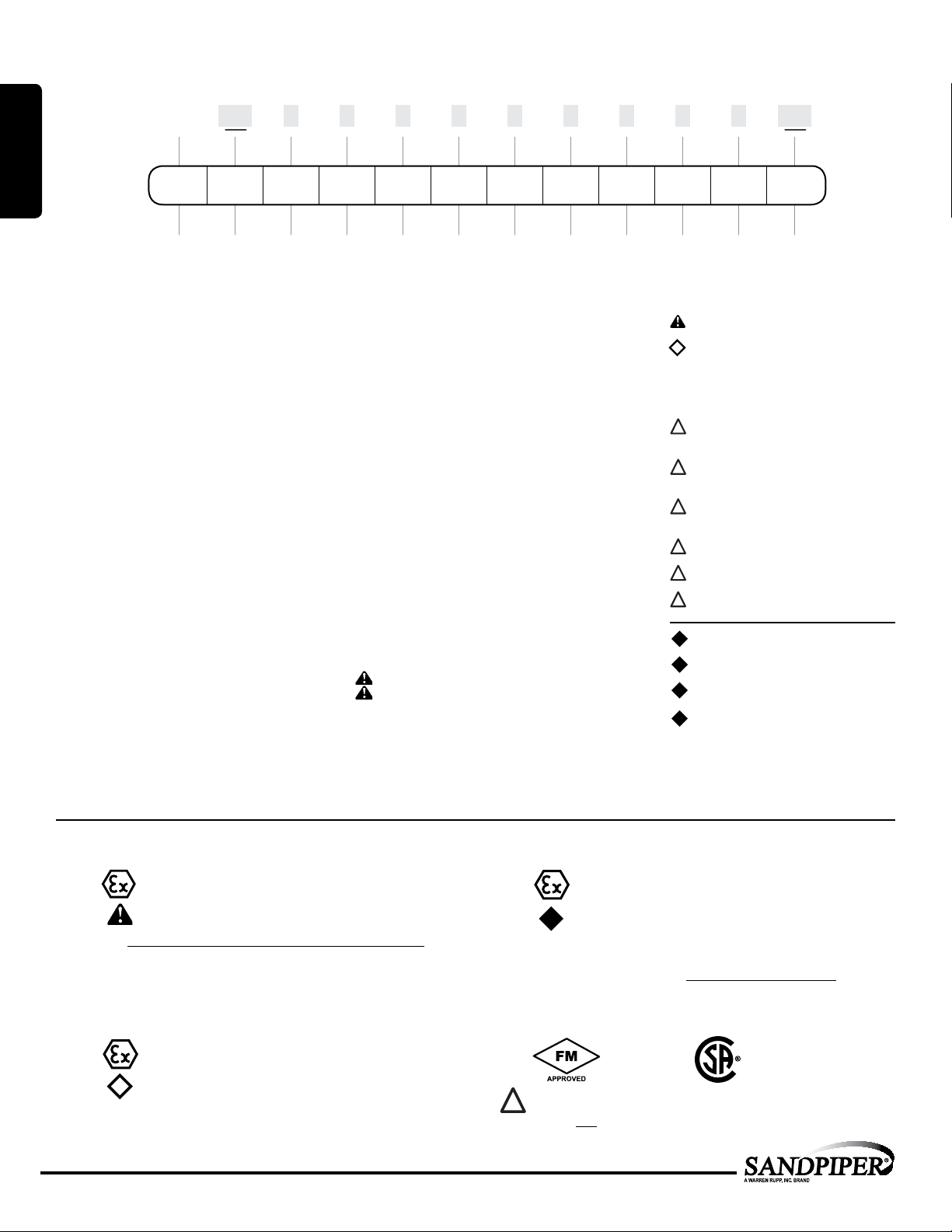
Explanation of Pump Nomenclature
II 2GD T5
II 2G Ex ia c IIC T5
II 2D c iaD 20 IP67 T100˚C
II 2G EEx m c T5
II 2D c IP65 T100°C
Your Model #:
S
__ ____ __ __ __ __ __ __ __ __ __ ____
(ll in from pump
nameplate)
1: PUMP SPECS
Pump Pump Check Design Wetted Diaphragm/
Brand Size Valve Level Material
Model #:
S XX X X X X X X X X X XX
Pump Brand
S SANDPIPER
®
Pump Size
15 1 1/2"
Check Valve Type
B Ball
W Weighted Ball
Design Level
1 Design Level
Wetted Material
A Aluminum
I Cast Iron
S Stainless Steel
H Alloy C
X Unpainted Aluminum
Diaphragm/Check Valve Materials
1 Santoprene/Santoprene
2 PTFE-Santoprene/PTFE
B Nitrile/Nitrile
C FKM/PTFE
E EPDM/EPDM
I EPDM/Santoprene
G PTFE-Neoprene/PTFE
M Santoprene/PTFE
N Neoprene/Neoprene
V FKM/FKM
Z One-Piece Bonded/PTFE
Check Valve Seat
A Aluminum
C Carbon Steel
S Stainless Steel
T PTFE
W UHMW
Non-Wetted Material Options
A Painted Aluminum
I Cast Iron
J Painted Aluminum w/PTFE
Coated Hardware
S Stainless Steel with
Stainless Steel Hardware
Y Painted Aluminum with
Stainless Steel Hardware
Z Cast Iron with
Stainless Steel Hardware
Porting Options
N NPT Threads
B BSP (Tapered) Threads
R Raised Face 150#
Threaded ANSI Flange
W Welded Raised Face 150# ANSI Flange Manifolds
Pump Style
S Standard
Pump Options
0 None
1 SoundDampeningMufer
2 MeshMufer
3 High temperature Air Valve
w/IntegralMufer
4 High temperature Air Valve
w/SoundDampeningMufer
5 High temperature Air Valve
w/MeshMufer
6 MetalMufer
7 Metal Muferwith
Grounding Cable
Check Valve
Check Valve Non-Wetted
Seat Material Options Style Options Options
Porting Pump Pump Kit
Kit Options
00. None
P0. 10.30VDC Pulse Output Kit
P1. Intrinsically-Safe 5.30VDC,
110/120VAC 220/240 VAC
Pulse Output Kit
P2. 110/120 or 220/240VAC
Pulse Output Kit
E0. Solenoid Kit with 24VDC Coil
E1. Solenoid Kit with 24VDC
Explosion-Proof Coil
E2. Solenoid Kit with 24VAC/12VDC Coil
E3. Solenoid Kit with 12VDC
Explosion-Proof Coil
E4. Solenoid Kit with 110VAC Coil
E5. Solenoid Kit with 110VAC
Explosion-Proof Coil
E6. Solenoid Kit with 220VAC Coil
E7. Solenoid Kit with 220VAC
Explosion-Proof Coil
E8. Solenoid Kit with 110VAC, 50 Hz
Explosion-Proof Coil
E9. Solenoid Kit with 230VAC, 50 Hz
Explosion-Proof Coil
S P. Stroke Indicator Pins
A1. Solenoid Kit with 12 VDC
ATEX Compliant Coil
A2. Solenoid Kit with 24 VDC
ATEX Compliant Coil
A3. Solenoid Kit with 110/120 VAC
50/60 Hz ATEX Compliant Coil
A4. Solenoid Kit with 220/240 VAC
50/60 Hz ATEX Compliant Coil
Your Serial #: (ll in from pump nameplate) _____________________________________
ATEX Detail
(1)
II 1G c T5
II 3/1 G c T5
II 1D c T100°C
I M1 c
I M2 c
II 2G c T5
II 3/2 G c T5
II 2D c T100°C
(2)
II 2G Ex ia c IIC T5
II 3/2 G Ex ia c IIC T5
II 2D Ex c ia 20 IP67 T100°C
Note: Pumps ordered with the options listed in (1) to the left are ATEX
compliant when ordered with kit option P1.
1 • Model S15 Metallic
Models equipped with Wetted Options I, S or H,
Non-Wetted Options I, S or Z, Pump Options 6 or
7, and Kit Option 0.
Note: See ATEX Explanation of EC-Type
Certicate
Models equipped with Wetted Options A, I, S, or H,
Non-Wetted Options A, I,Y, or Z, Pump Options 6 or
7, and Kit Option 0.
Note: See ATEX Explanation of Type Examination
Certicate
(3)
II 2G EEx m c II T5
II 3/2 2G EEx m c II T5
II 2D c IP65 T100°C
Note: Pumps ordered with the options listed in (1) to the left are
ATEX compliant when ordered with kit option A1, A2, A3, or A4.
Compressed Air Temperature Range: Maximum Ambient Temperature
to plus 50°C.
*Note: See page 16 for Special Conditions For Safe Use.
(4)
IEC EEX m T4
Note: Pump models equipped with these explosion-proof solenoid kit options
E1, E3, E5, E7, E8 or E9, are certied and approved by the above agencies.
They are NOT ATEX compliant.
sa n d pip er pu mp .c om
s15mdl1sm-rev0614
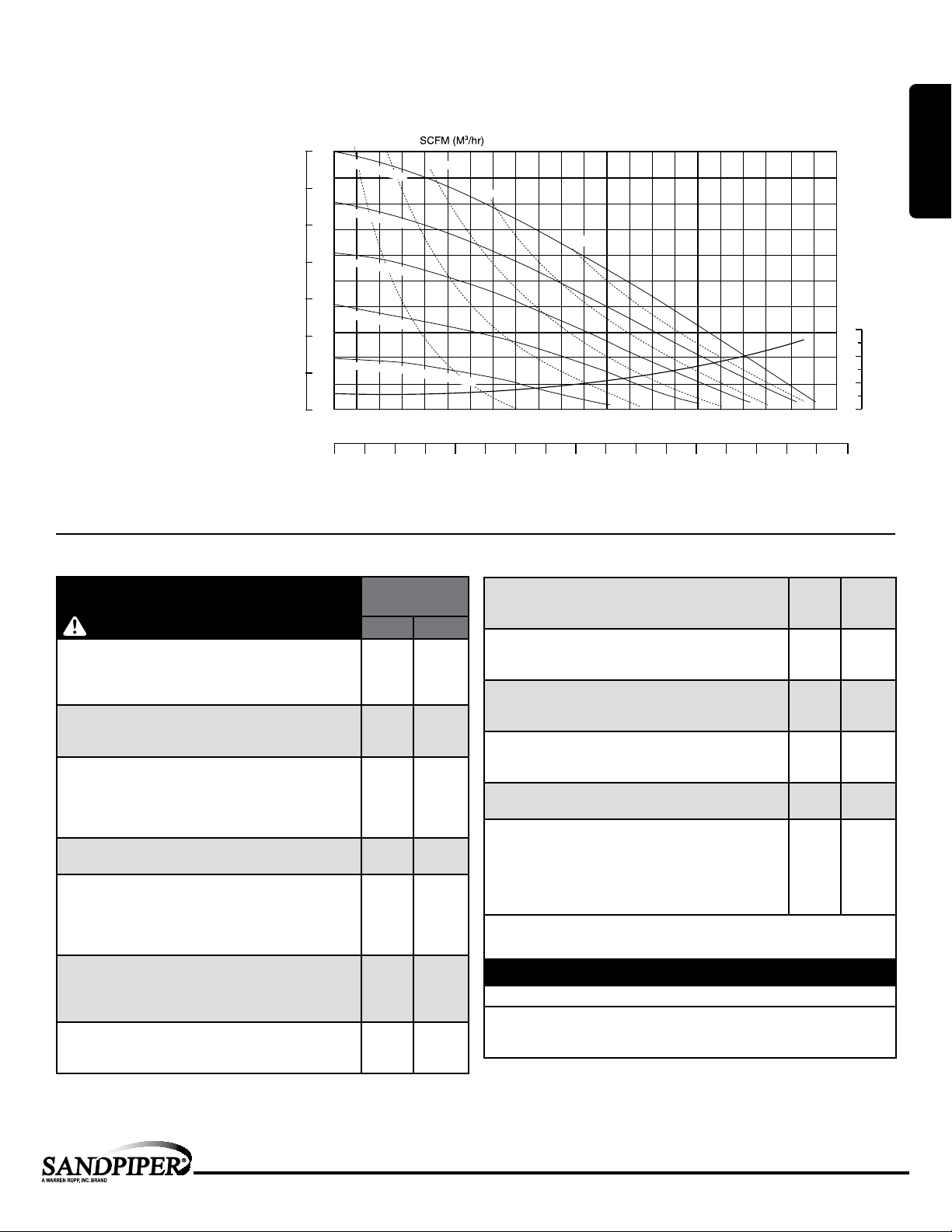
Performance
S15 METALLIC
SUCTION/DISCHARGE PORT SIZE
• 1½" NPT (internal)
• 1½" BSP Tapered (internal)
• 1½" ANSI 150# Raised Face Flanges
CAPACITY
• 0 to 106 gallons per minute
(0 to 401 liters per minute)
AIR DISTRIBUTION VALVE
• No-lube, no-stall design
SOLIDS-HANDLING
• Up to .25 in. (6mm)
HEADS UP TO
• 125 psi or 289 ft. of water
(8.6 Kg/cm
DISPLACEMENT/STROKE
• .41 Gallon / 1.55 liter
MAX OPERATING PRESSURE
• 125 psi (8.6 bar)
SHIPPING WEIGHT
• Aluminum 53 lbs. (24kg)
• Cast Iron 93 lbs. (42kg)
• Stainless Steel 95 lbs. (43kg)
2
or 86 meters)
BAR
100
7
90
6
80
5
70
60
4
50
HEAD
3
40
30
2
20
1
10
0
PSI
10 (17)
100 PSI (6.8 Bar)
80 PSI (5.44 Bar)
60 PSI (4.08 Bar)
40 PSI (2.72 Bar)
20 PSI (1.36 Bar)
0
0
Performance based on the following: elastomer fitted pump, flooded suction, water at ambient conditions.
The use of other materials and varying hydraulic conditions may result in deviations in excess of 5%.
20 (34)
30 (51)
Air Inlet Pressure
20
10
30
MODEL S15 Metallic Performance Curve
40 (68)
50 (85)
50
40
70 80 90 100 11060
U.S. Gallons per minute
Liters per minute
CAPACITY
FEET
30
20
10
0
4254003753503253002752502252001751501251007550250
1: PUMP SPECS
NPSHR
METERS
9.1
7.6
6
4.5
3
1.5
Materials
Material Prole:
CAUTION! Operating temperature limitations are as follows:
Conductive Acetal: Tough, impact resistant, ductile. Good
abrasion resistance and low friction surface. Generally inert, with
Operating
Temperatures:
Max. Min.
190°F
88°C
-20°F
-29°C
good chemical resistance except for strong acids and oxidizing
agents.
EPDM: Shows very good water and chemical resistance. Has
poor resistance to oils and solvents, but is fair in ketones and
280°F
138°C
-40°F
-40°C
alcohols.
FKM: (Fluorocarbon) Shows good resistance to a wide range
of oils and solvents; especially all aliphatic, aromatic and
350°F
177°C
-40°F
-40°C
halogenated hydrocarbons, acids, animal and vegetable oils.
Hot water or hot aqueous solutions (over 70°F(21°C)) will
attack FKM.
Hytrel®: Good on acids, bases, amines and glycols at room
temperatures only.
Neoprene: All purpose. Resistance to vegetable oils. Generally
not affected by moderate chemicals, fats, greases and many
220°F
104°C
200°F
93°C
-20°F
-29°C
-10°F
-23°C
oils and solvents. Generally attacked by strong oxidizing acids,
ketones, esters and nitro hydrocarbons and chlorinated aromatic
hydrocarbons.
Nitrile: General purpose, oil-resistant. Shows good solvent, oil,
water and hydraulic uid resistance. Should not be used with
190°F
88°C
-10°F
-23°C
highly polar solvents like acetone and MEK, ozone, chlorinated
hydrocarbons and nitro hydrocarbons.
Nylon: 6/6 High strength and toughness over a wide
temperature range. Moderate to good resistance to fuels, oils
180°F
82°C
32°F
0°C
and chemicals.
Ambient temperature range: -20°C to +40°C
Process temperature range: -20°C to +80°C for models rated as category 1 equipment
-20°C to +100°C for models rated as category 2 equipment
In addition, the ambient temperature range and the process temperature range do not exceed the operating temperature range of the applied non-metallic parts as listed in the manuals of the pumps.
Polypropylene: A thermoplastic polymer. Moderate tensile
and ex strength. Resists stong acids and alkali. Attacked by
chlorine, fuming nitric acid and other strong oxidizing agents.
PVDF: (Polyvinylidene Fluoride) A durable uoroplastic with
excellent chemical resistance. Excellent for UV applications.
High tensile strength and impact resistance.
Santoprene®: Injection molded thermoplastic elastomer with
no fabric layer. Long mechanical ex life. Excellent abrasion
resistance.
UHMW PE: A thermoplastic that is highly resistant to a broad
range of chemicals. Exhibits outstanding abrasion and impact
resistance, along with environmental stress-cracking resistance.
Urethane: Shows good resistance to abrasives. Has poor
resistance to most solvents and oils.
Virgin PTFE: (PFA/TFE) Chemically inert, virtually impervious.
Very few chemicals are known to chemically react with PTFE;
molten alkali metals, turbulent liquid or gaseous uorine and
a few uoro-chemicals such as chlorine triuoride or oxygen
diuoride which readily liberate free uorine at elevated
temperatures.
Maximum and Minimum Temperatures are the limits for which these materials can be operated.
Temperatures coupled with pressure affect the longevity of diaphragm pump components.
Maximum life should not be expected at the extreme limits of the temperature ranges.
Metals:
Alloy C: Equal to ASTM494 CW-12M-1 specication for nickel and nickel alloy.
Stainless Steel: Equal to or exceeding ASTM specication A743 CF-8M for corrosion
resistant iron chromium, iron chromium nickel and nickel based alloy castings for
general applications. Commonly referred to as 316 Stainless Steel in the pump industry.
Forspecicapplications,alwaysconsulttheChemicalResistanceChart.
180°F
82°C
250°F
121°C
275°F
135°C
180°F
82°C
150°F
66°C
220°F
104°C
32°F
0°C
0°F
-18°C
-40°F
-40°C
-35°F
-37°C
32°F
0°C
-35°F
-37°C
sa n d pip er pu mp .c om
s15mdl1sm-rev0614
Model S15 Metallic • 2
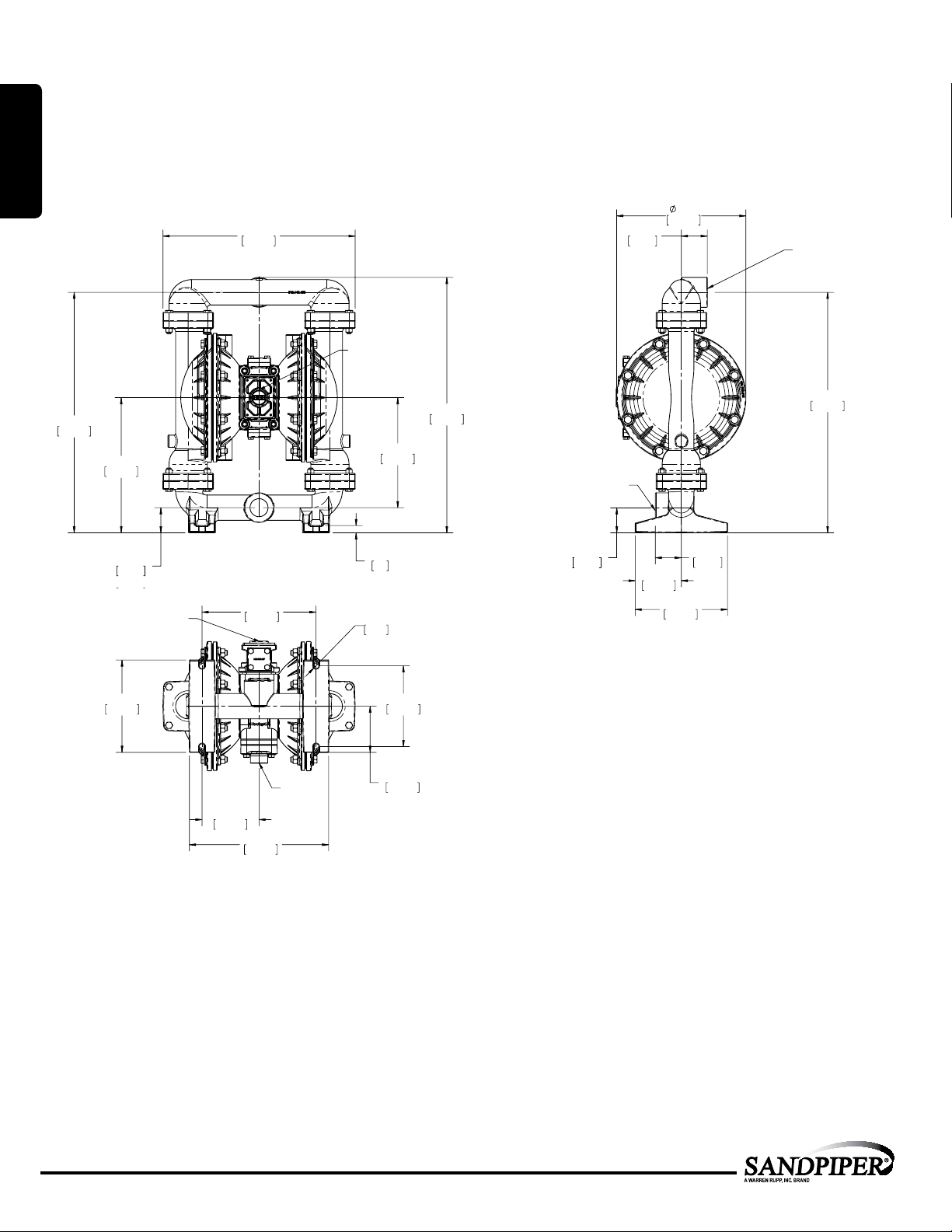
Dimensional Drawings
11.19
284.16
2.25
57.15
20.83
529.20
2.25
57.15
4.00
2.18
55.39
1 1/2 NPT DISCHARGE PORT
1 1/2 NPT SUCTION PORT
16.65
422.95
2.18
55.39
11.71
297.55
20.83
529.20
22.13
562.09
9.53
242.16
.6316
1" NPT EXHAUST PORT
11.19
284.16
2.25
57.15
20.83
529.20
2.25
57.15
8.00
203.20
4.00
101.60
2.18
55.39
1 1/2 NPT DISCHARGE PORT
1 1/2 NPT SUCTION PORT
S15 Metallic - NPT
Dimensions in inches (mm dimensions in brackets). Dimensional Tolerance:±1/8" (± 3mm)
The dimensions on this drawing are for reference only. A certied drawing can be requested if physical dimensions are needed.
1: PUMP SPECS
20.83
529.20
11.71
297.55
2.18
55.39
1" NPT EXHAUST PORT
16.65
422.95
9.88
250.83
11.19
1" NPT EXHAUST PORT
22.13
562.09
9.53
242.16
1 1/2 NPT SUCTION PORT
2.18
.6316
R.25
6.35
55.39
2.25
57.15
4.00
101.60
284.16
8.00
203.20
2.25
57.15
1 1/2 NPT DISCHARGE PORT
20.83
529.20
7.00
203.20
AIR INLET
3/4" NPT
4.94
125.46
12.06
306.44
177.80
4.00
101.60
8.00
3 • Model S15 Metallic
sa n d pip er pu mp .c om
s15mdl1sm-rev0614
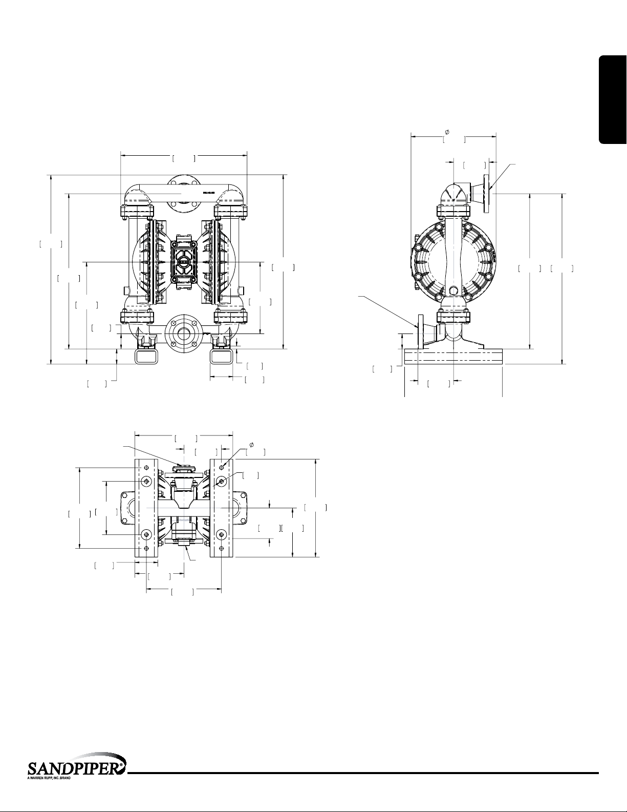
Dimensional Drawings
20.41
518.41
4.68
118.87
4.68
118.87
11.19
284.16
2.00
50.80
22.41
569.21
DISCHARGE PORT
1 1/2" RF 150# ANSI
5/8" DIA,(4) HOLES EQ. SPC'D
ON 3.88" DIA. BOLT CIRCLE
SUCTION PORT
1 1/2" RF 150# ANSI
5/8" DIA.,(4) HOLES EW. SPC'D. ON
3.88" DIA. BOLT CIRCLE
16.63
422.28
22.91
581.91
.38
9.53
2.00
50.80
3.00
76.20
2.00
50.80
13.41
340.55
9.41
238.95
20.41
518.41
4.68
118.87
4.68
118.87
11.19
284.16
2.00
50.80
22.41
569.21
12.87
326.90
DISCHARGE PORT
1 1/2" RF 150# ANSI
5/8" DIA,(4) HOLES EQ. SPC'D
ON 3.88" DIA. BOLT CIRCLE
SUCTION PORT
1 1/2" RF 150# ANSI
5/8" DIA.,(4) HOLES EW. SPC'D. ON
3.88" DIA. BOLT CIRCLE
S15 Metallic - ANSI Flange
Dimensions in inches (mm dimensions in brackets). Dimensional Tolerance:±1/8" (± 3mm)
The dimensions on this drawing are for reference only. A certied drawing can be requested if physical dimensions are needed.
24.85
631.19
20.41
518.41
13.41
340.55
2.00
2.00
50.80
50.80
11.19
284.16
16.63
422.28
22.91
581.91
SUCTION PORT
1 1/2" RF 150# ANSI
9.41
238.95
.38
9.53
3.00
76.20
5/8" DIA.,(4) HOLES EW. SPC'D. ON
3.88" DIA. BOLT CIRCLE
2.00
50.80
4.68
118.87
4.68
118.87
DISCHARGE PORT
1 1/2" RF 150# ANSI
5/8" DIA,(4) HOLES EQ. SPC'D
ON 3.88" DIA. BOLT CIRCLE
22.41
20.41
518.41
569.21
1: PUMP SPECS
1" NPT EXHAUST PORT
7.00
10.61
177.80
269.49
3.00
76.20
12.88
327.03
4.94
125.41
6.44
163.51
9.88
250.83
BOTTOM VIEW
AIR INLET
3/4" NPT
.50
MOUNTING HOLES
12.70
R.25
6.35
4.00
6.44
101.60
163.45
12.87
326.90
sa n d pip er pu mp .c om
s15mdl1sm-rev0614
Model S15 Metallic • 4
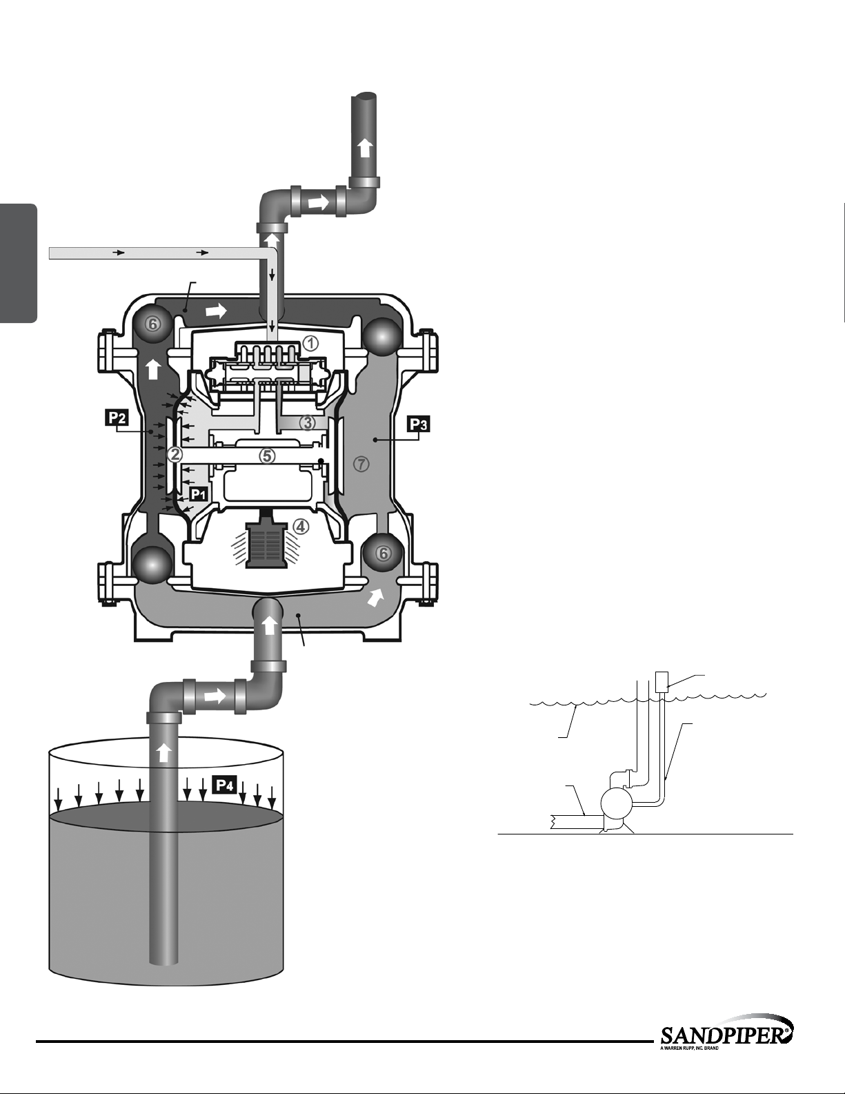
Principle of Pump Operation
SAFE AIR
EXHAUST
DISPOSAL
AREA
MUFFLER
Air-Operated Double Diaphragm (AODD) pumps are powered
by compressed air or nitrogen.
2: INSTAL & OP
Discharge
Stroke
Air Line
Discharged
Fluid
Suction
Stroke
The main directional (air) control valve
compressed air to an air chamber, exerting uniform pressure
over the inner surface of the diaphragm
the exhausting air
is directed through the air valve assembly(s) to an exhaust
port
.
④
As inner chamber pressure
pressure
together creating discharge on one side and suction on the
opposite side. The discharged and primed liquid’s directions
are controlled by the check valves (ball or ap)
The pump primes as a result of the suction stroke. The
suction stroke lowers the chamber pressure
the chamber volume. This results in a pressure differential
necessary for atmospheric pressure
through the suction piping and across the suction side check
valve and into the outer uid chamber
Suction (side) stroking also initiates the reciprocating
(shifting, stroking or cycling) action of the pump. The suction
diaphragm’s movement is mechanically pulled through its
stroke. The diaphragm’s inner plate makes contact with an
actuator plunger aligned to shift the pilot signaling valve.
Once actuated, the pilot valve sends a pressure signal to the
opposite end of the main directional air valve, redirecting the
compressed air to the opposite inner chamber.
(P2), the rod
from behind the opposite diaphragm
③
(P1) exceeds liquid chamber
connected diaphragms shift
⑤
distributes
①
. At the same time,
②
orientation.
⑥
(P3) increasing
(P4) to push the uid
.
⑦
5 • Model S15 Metallic
Primed
Fluid
SUBMERGED ILLUSTRATION
MUFFLER
LIQUID
LEVEL
SUCTION
LINE
Pump can be submerged if the pump materials of construction
are compatible with the liquid being pumped. The air exhaust
must be piped above the liquid level. When the pumped product
source is at a higher level than the pump (ooded suction
condition), pipe the exhaust higher than the product source to
prevent siphoning spills.
sa n d pip er pu mp .c om
s15mdl1sm-rev0614
1" DIAMETER AIR
EXHAUST PIPING
 Loading...