


SERVICE & OPERATING MANUAL
Model S07 |
|
Non-Metallic Design Level 1 |
|
Table of Contents |
|
Engineering Data and Temperature Limitations........................................................ |
1 |
Explanation of Pump Nomenclature.......................................................................... |
2 |
Performance Curve................................................................................................... |
3 |
Performance Curve, Trihedral Model ....................................................................... |
4 |
Dimensions: S07 Non-Metallic.................................................................................. |
5 |
Metric Dimensions: S07 Non-Metallic....................................................................... |
6 |
Principle of Pump Operation..................................................................................... |
7 |
Installation and Start-up............................................................................................ |
7 |
Air Supply.................................................................................................................. |
7 |
Air Valve Lubrication................................................................................................. |
7 |
Air Line Moisture....................................................................................................... |
7 |
Air Inlet and Priming.................................................................................................. |
7 |
Between Uses........................................................................................................... |
7 |
Installation Guide...................................................................................................... |
8 |
Troubleshooting........................................................................................................ |
9 |
Warranty.................................................................................................................... |
9 |
Important Safety Information................................................................................... |
10 |
Material Codes........................................................................................................ |
11 |
Composite Repair Parts Drawing............................................................................ |
12 |
Overlay Option Drawing.......................................................................................... |
12 |
Available Service and Conversion Kits................................................................... |
12 |
Composite Repair Parts List................................................................................... |
13 |
Air Valve Assembly Drawing and Parts List............................................................ |
14 |
Air Valve Assembly Servicing.................................................................................. |
15 |
Air Valve with Stroke Indicator Drawing and Parts List........................................... |
16 |
Air Valve with Stroke Indicator Servicing................................................................. |
17 |
Pilot Valve Servicing, Assembly Drawing and Parts List........................................ |
18 |
U.S. Patent # 400,210 5,996,627; 6,241,487
Solenoid Shifted Valve Drawing and Parts List....................................................... |
19 |
Solenoid Shifted Air Distribution Valve Option........................................................ |
20 |
Intermediate Assembly Drawing.............................................................................. |
21 |
Intermediate Assembly Servicing............................................................................ |
21 |
Modular Check Ball Valve Drawing......................................................................... |
22 |
Modular Check Ball Valve Servicing....................................................................... |
22 |
Modular Trihedral Check Valve Option Drawing and Parts List.............................. |
23 |
Modular Trihedral Check Valve Servicing............................................................... |
24 |
Diaphragm Service Drawing, Non-Overlay............................................................. |
25 |
Diaphragm Service Drawing with Overlay .............................................................. |
25 |
Diaphragm Servicing, Overlay Diaphragm Servicing ............................................. |
26 |
Dual Port Option Drawing....................................................................................... |
27 |
Dual Porting Options............................................................................................... |
28 |
Dual Porting of both suction and discharge ends of the pump................................ |
28 |
Single Porting of the suction and dual porting of the pump discharge.................... |
28 |
Dual Porting of the suction and single porting of the pump discharge.................... |
28 |
Single Port Suction Repair Parts List...................................................................... |
29 |
Single Port Discharge Repair Parts List.................................................................. |
29 |
Dual Port Suction and Discharge Repair Parts List................................................ |
29 |
Pumping Hazardous Liquids................................................................................... |
30 |
Converting the Pump for Piping the Exhaust Air..................................................... |
30 |
Exhaust Conversion Drawing.................................................................................. |
30 |
Converted Exhaust Illustration................................................................................ |
30 |
Pulse Output Kit Drawing, Option........................................................................... |
31 |
Optional Muffler Configurations Drawing................................................................ |
32 |
CE Declaration of Conformity.................................................................................. |
33 |
|
WARREN RUPP®, IDEX AODD, Inc. • A Unit of IDEX Corporation • 800 |
N. Main St., Mansfield, Ohio 44902 USA |
s07nmdl1sm-rev0614 |
Telephone (419) 524-8388 • Fax (419) 522-7867 |
• warrenrupp.com |
Quality System |
|
|
|
S07 Non-Metallic |
||
ISO9001 Certified |
|
|
|
Ball Valve |
|
|
|
|
|
|
|
||
Environmental |
|
|
|
Design Level 1 |
||
Management System |
|
|
U.S. Patent # |
|||
ISO 14001 Certified |
|
|
|
|
||
|
|
5,851,109; 5,996,627; |
|
|
||
|
|
|
Air Operated |
|
||
|
|
|
400,210; 6,241,487 |
|
||
|
|
|
Other U.S. Patents |
Double Diaphragm Pump |
||
|
|
|
Applied for |
|||
|
|
|
|
ENGINEERING, PERFORMANCE |
||
|
|
|
|
& CONSTRUCTION DATA |
||
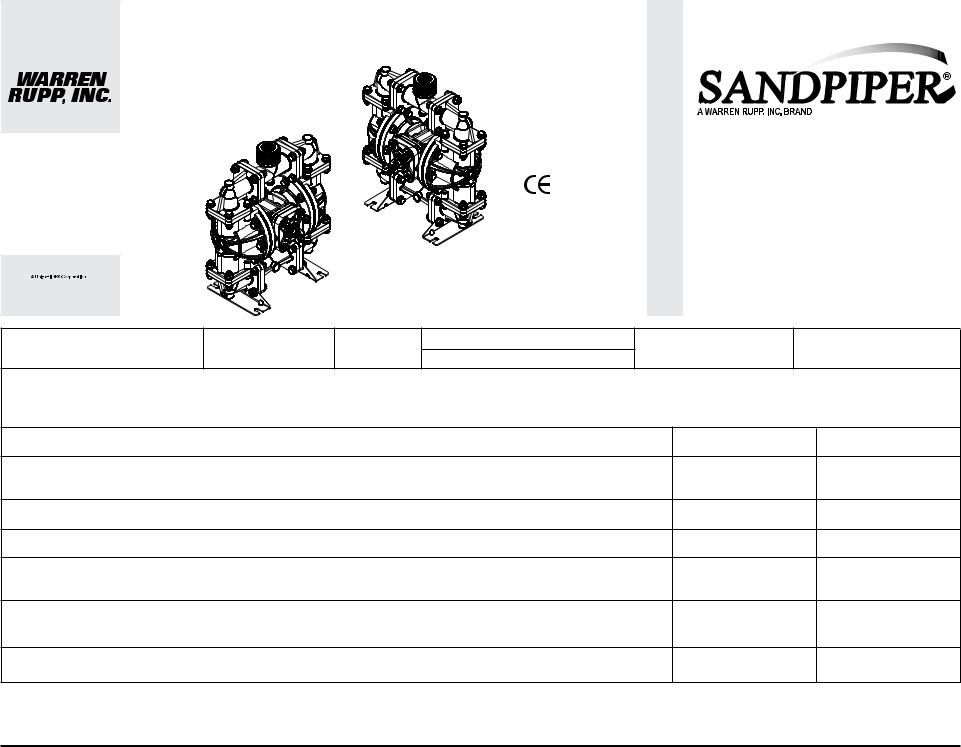
INTAKE/DISCHARGE PIPE SIZE |
CAPACITY |
AIR VALVE |
SOLIDS-HANDLING |
HEADS UP TO |
DISPLACEMENT/STROKE |
|
Ball Valve S07B Models - Up to .15 in.(4mm) |
||||||
Internal Threads ¾" NPT or ¾" BSP Tapered |
0 to 23 US gallons per minute |
No-lube, no-stall |
100 psi or 231 ft. of water |
.026 US gallon / .098 liter |
||
Trihedral Valve S07T Models - Up tp .36in |
||||||
External Threads 1½" NPT or1½” BSP Tapered |
(0 to 87 liters per minute) |
design |
(7 bar or 70 meters) |
|
||
(9.1mm) Diameter or .16in2 area (10.3cm2) |
|
|||||
|
|
|
|
|||
CAUTION! Operating temperature limitations are as follows: |
|
Operating Temperatures |
||||
Materials |
|
|
|
|||
|
|
|
Maximum |
Minimum |
||
Santoprene®:Injection molded thermoplastic elastomer with no fabric layer. Long mechanical flex life. Excellent abrasion |
275°F |
-40°F |
||||
resistance. |
|
|
|
135°C |
-40°C |
|
Virgin PTFE: Chemically inert, virtually impervious. Very few chemicals are known to react chemically with PTFE: molten alkali metals, |
|
|
||||
turbulent liquid or gaseous fluorine and a few fluoro-chemicals such as chlorine trifluoride or oxygen difluoride which readily |
220°F |
-35°F |
||||
liberate free fluorine at elevated temperatures. |
|
|
104°C |
-37°C |
||
PVDF: |
|
|
|
250°F |
0°F |
|
|
|
|
|
121°C |
-18°C |
|
Polypropylene: |
|
|
|
180°F |
32°F |
|
|
|
|
|
82°C |
0°C |
|
Nitrile: General purpose, oil-resistant. Shows good solvent, oil, water and hydraulic fluid resistance. Should not be used |
190°F |
-10°F |
||||
with highly polar solvents like acetone and MEK, ozone, chlorinated hydrocarbons and nitro hydrocarbons. |
88°C |
-23°C |
||||
FKM (Fluorocarbon): Shows good resistance to a wide range of oils and solvents; especially all aliphatic, aromatic and halogenated |
350°F |
-40°F |
||||
hydrocarbons, acids, animal and vegetable oils. Hot water or hot aqueous solutions (over 70°F) will attack FKM. |
177°C |
-40°C |
||||
Nylon: |
|
|
|
180°F |
32°F |
|
|
|
|
82°C |
0°C |
||
|
|
|
|
|||
For specific applications, always consult the Warren Rupp “Chemical Resistance Chart” |
|
|
|
|
||
CAUTION: Nonmetallic pumps and plastic components are not UV stabilized. Ultraviolet radiation can damage these parts and negatively affect material properties. |
|
|
||||
Do not expose to UV light for extended periods of time. |
|
|
|
|
|
|
SANDPIPER® pumps are designed to be powered only by compressed air. |
|
|
|
|||
s07nmdl1sm-rev0614 |
|
|
|
Models S07 Non-Metallic Page 1 |
||
S07 Non-Metallic · Design Level 1· Ball Valve
|
Pump |
Pump |
Check |
Design |
Wetted |
Diaphragm/ |
Check |
Non-Wetted |
Porting |
Pump |
Pump |
Kit |
Shipping |
|
Type |
Valve |
Check Valve |
Valve |
Material |
Weight |
|||||||||
Brand |
Size |
Level |
Material |
Options |
Style |
Options |
||||||||
|
Type |
|
|
Options |
Seat |
Options |
Options |
lbs (kg) |
||||||
S07B1P1PPNS000. |
S |
07 |
B |
1 |
P |
1 |
P |
P |
N |
S |
0 |
00. |
17 (8) |
|
S07B1P2PPNS000. |
S |
07 |
B |
1 |
P |
2 |
P |
P |
N |
S |
0 |
00. |
17 (8) |
|
S07B1K1KPNS000. |
S |
07 |
B |
1 |
K |
1 |
K |
P |
N |
S |
0 |
00. |
21 (9.5) |
|
S07B1K2KPNS000. |
S |
07 |
B |
1 |
K |
2 |
K |
P |
N |
S |
0 |
00. |
21 (9.5) |
|
S07B1N1NPNS000. |
S |
07 |
B |
1 |
N |
1 |
N |
P |
N |
S |
0 |
00. |
18 (9) |
|
S07B1N2NPNS000. |
S |
07 |
B |
1 |
N |
2 |
N |
P |
N |
S |
0 |
00. |
18 (9) |
|
S07T1P7PPNS000. |
S |
07 |
T |
1 |
P |
7 |
P |
P |
N |
S |
0 |
00. |
17 (8) |
|
S07T1P8PPNS000. |
S |
07 |
T |
1 |
P |
8 |
P |
P |
N |
S |
0 |
00. |
17 (8) |
|
S07T1PBPPNS000. |
S |
07 |
T |
1 |
P |
B |
P |
P |
N |
S |
0 |
00. |
17 (8) |
|
S07B1P1PPBS000. |
S |
07 |
B |
1 |
P |
1 |
P |
P |
B |
S |
0 |
00. |
17 (8) |
|
S07B1P2PPBS000. |
S |
07 |
B |
1 |
P |
2 |
P |
P |
B |
S |
0 |
00. |
17 (8) |
|
S07B1K1KPBS000. |
S |
07 |
B |
1 |
K |
1 |
K |
P |
B |
S |
0 |
00. |
21 (9.5) |
|
S07B1K2KPNS000. |
S |
07 |
B |
1 |
K |
2 |
K |
P |
B |
S |
0 |
00. |
21 (9.5) |
|
S07B1N1NPBS000. |
S |
07 |
B |
1 |
N |
|
N |
P |
B |
S |
0 |
00. |
18 (9) |
|
S07B1N2NPBS000. |
S |
07 |
B |
1 |
N |
2 |
N |
P |
B |
S |
0 |
00. |
18 (9) |
|
S07T1P7PPBS000. |
S |
07 |
T |
1 |
P |
7 |
P |
P |
B |
S |
0 |
00. |
21 (9.5) |
|
S07T1P8PPBS000. |
S |
07 |
T |
1 |
P |
8 |
P |
P |
B |
S |
0 |
00. |
21 (9.5) |
|
S07T1PBPPBS000. |
S |
07 |
T |
1 |
P |
B |
P |
P |
B |
S |
0 |
00. |
21 (9.5) |
Pump Brand |
Diaphragm/Check Valve Materials |
Porting Options |
Kit Options |
||
S= SANDPIPER® |
1= |
Santoprene/Santoprene |
N= NPT Threads |
00.= None |
|
Pump Size |
2= |
Virgin PTFE-Santoprene |
1= Dual Porting (NPT) |
P0.= 10-30VDC Pulse Output Kit |
|
|
Backup/Virgin PTFE |
2= Top Dual Porting (NPT) |
P1.= Intrinsically-Safe 5-30VDC,110/120VAC, 220/240VAC |
||
07= 3/4" |
7= |
Santoprene/Nitrile |
3= Bottom Dual Porting (NPT) |
Pulse Output Kit |
|
Check Valve Type |
8= Virgin PTFE-Santoprene |
B= BSP Threads (tapered) |
P2.= 110/120 or 220/240VAC Pulse Output Kit |
||
|
Backup/FKM |
4= Dual Porting (BSP) (tapered) |
E0.= Solenoid Kit w/24VDC Coil |
||
B= Ball |
B= Nitrile/Nitrile |
5= Top Dual Porting (BSP) (tapered) |
E1.= Solenoid Kit 24VDC Explosion-Proof Coil |
||
T= Tihedral |
U= Polyurethane/Polyurethane |
6= Bottom Dual Porting (BSP) (tapered) |
E2.= Solenoid Kit w/24VAC/12VDC Coil |
||
Design Level |
Z= One-Piece Bonded/PTFE |
|
E3.= Solenoid Kit w/12VDC Explosion-Proof Coil |
||
|
|
Pump Style |
E4.= Solenoid Kit w/110VAC Coil |
||
1= Design Level 1 |
Check Valve Seat |
S= Standard |
E5.= Solenoid Kit w/110VAC 60 Hz Explosion-Proof Coil |
||
|
K= PVDF |
|
E6.= Solenoid Kit w/220VAC Coil |
||
Wetted Material |
N= Nylon |
Pump Options |
E7.= Solenoid Kit w/220VAC 60 Hz Explosion-Proof Coil |
||
K= PVDF |
P= Polypropylene |
0= None |
E8.= Solenoid Kit w/110VAC 50 Hz Explosion-Proof Coil |
||
N= Nylon |
|
|
1= Sound Dampening |
E9.= Solenoid Kit w/230VAC 50 Hz Explosion-Proof Coil |
|
P= Polypropylene |
Non-Wetted Material Options |
2= Mesh Muffler |
SP= Stroke Indicator Pins |
||
|
P= Polypropylene |
6= Metal Muffler |
|
|
|
|
I= Polypropylene with PTFE Hardware |
|
|
|
|
|
|
|
|
|
|
s07nmdl1sm-rev0614 |
|
|
|
Models S07 Non-Metallic Page 2 |
|
S07 Non-Metallic Performance Curve Curve
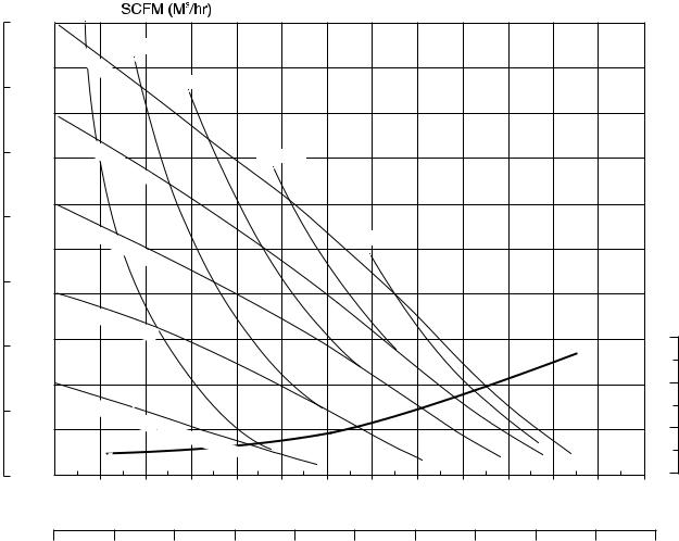
MODEL S07 Ball Valve Non-Metallic Performance Curve
|
BAR |
|
|
|
|
|
|
Performance based on the following: elastomer fitted pump, flooded suction, water at ambient conditions. |
|
||||||||||||||
|
PSI |
|
|
|
|
|
|
|
The use of other materials and varying hydraulic conditions may result in deviations in excess of 5%. |
|
|||||||||||||
|
4 (7) |
|
|
|
|
|
|
|
|
|
|
|
|
|
|
|
|
|
|
||||
|
7 |
100 |
|
|
|
|
|
|
|
|
|
|
|
|
|
|
|
|
|
|
|||
|
|
|
|
|
|
|
|
|
|
|
|
|
|
|
|
|
|
|
|
|
|
||
|
|
|
100 |
PSI |
|
8 (13.5) |
|
|
|
|
|
|
|
|
|
|
|
|
|||||
|
|
90 |
|
(6 |
|
|
|
|
|
|
|
|
|
|
|
|
|
|
|
|
|
||
|
|
|
|
|
|
|
|
|
|
|
|
|
|
|
|
|
|
|
|
|
|||
|
|
|
|
|
|
. |
|
|
|
|
|
|
|
|
|
|
|
|
|
|
|
|
|
|
|
|
|
|
|
8 |
|
|
|
12 (20) |
|
|
|
|
|
|
|
|
|
|
|
||
|
6 |
|
|
|
|
|
Bar) |
|
|
|
|
|
|
|
|
|
|
|
|||||
|
|
|
|
|
|
|
|
|
|
|
|
|
|
|
|
|
|
|
|||||
|
|
|
|
|
|
|
|
|
|
|
|
|
|
|
|
|
|
|
|
||||
|
|
80 |
|
|
|
|
|
|
|
|
|
|
|
|
|
|
|
|
|
|
|
|
|
|
|
|
80 |
PSI |
|
|
|
|
|
|
|
|
|
|
|
|
|
|
|
|
|
|
|
|
5 |
70 |
|
(5. |
|
|
|
|
|
|
|
16 (27) |
|
|
|
|
|
|
|
|
|
||
|
|
|
|
|
|
|
|
|
|
|
|
|
|
|
|
|
|
|
|||||
|
|
|
|
|
|
44 |
Bar) |
|
|
|
|
|
|
|
|
|
|
|
NPSHR |
|
|||
|
|
|
|
|
|
|
|
|
|
|
|
|
|
|
|
|
|
|
|
||||
|
4 |
60 |
60 |
|
|
|
|
|
|
|
|
|
|
|
|
|
|
|
|
|
|
|
|
HEAD |
|
PSI |
|
|
|
|
|
|
|
|
|
|
|
|
|
|
|
|
|
|
|||
|
|
(4. |
|
|
|
|
|
|
|
|
|
20 (34) |
|
|
|
|
|
|
|||||
|
|
|
|
|
|
|
|
|
|
|
|
|
|
|
|
|
|
|
|||||
|
|
|
|
|
|
|
|
|
|
|
|
|
|
|
|
|
|
|
|
||||
|
50 |
|
|
|
08 |
Bar) |
|
|
|
|
|
|
|
|
|
|
|
|
|
||||
|
|
|
|
|
|
|
|
|
|
|
|
|
|
|
|
|
|
|
METERS |
||||
|
|
|
|
|
|
|
|
|
|
|
|
|
|
|
|
|
|
|
|
||||
3 |
40 |
|
|
|
|
|
|
|
|
|
|
|
|
|
|
|
|
|
|
|
FEET |
||
|
40 |
|
|
|
|
|
|
|
|
|
|
|
|
|
|
|
|
|
|
||||
|
|
PSI (2. |
|
|
|
|
|
|
|
|
|
|
|
|
|
|
|
||||||
|
|
|
|
|
|
|
|
|
|
|
|
|
|
|
|
|
|
|
|
|
|||
|
|
30 |
|
|
|
72 |
Bar) |
|
|
|
|
|
|
|
|
|
|
|
30 |
9.1 |
|||
|
2 |
|
|
|
|
|
|
|
|
|
|
|
|
|
|
|
|
|
|
||||
|
|
|
|
|
|
|
|
|
|
|
|
|
|
|
|
|
|
|
|
||||
|
|
|
|
|
|
|
|
|
|
|
|
|
|
|
|
|
|
|
|
|
25 |
7.6 |
|
|
|
|
|
|
|
|
|
|
|
|
|
|
|
|
|
|
|
|
|
|
|
||
|
|
20 |
20 |
|
|
|
|
|
|
|
|
|
|
|
|
|
|
|
|
|
|
20 |
6 |
|
1 |
|
PSI (1. |
|
|
|
|
|
|
|
|
|
|
|
|
|
|
|
15 |
4.5 |
|||
|
|
|
|
|
|
|
|
|
|
|
|
|
|
|
|
|
|
||||||
|
|
10 |
|
|
|
36 |
Bar) |
Air |
|
|
|
|
|
|
|
|
|
|
10 |
3 |
|||
|
|
|
|
|
|
|
|
|
Inlet |
|
|
|
|
|
|
|
|
|
|||||
|
|
|
|
|
|
|
|
|
|
|
|
|
|
|
|
|
|
|
|||||
|
|
|
|
|
|
|
|
|
|
|
|
|
|
|
|
|
|
|
|
|
|
|
|
|
|
|
|
|
|
|
|
|
|
|
|
Pressure |
|
|
|
|
|
|
|
|
5 |
1.5 |
|
|
0 |
0 |
0 |
2 |
|
|
|
|
4 |
|
6 |
8 |
10 |
12 |
14 |
16 |
18 |
20 |
22 |
24 |
26 |
|
|
|
|
|
|
|
|
|
|
|
|||||||||||||||
U.S. Gallons per minute
0 |
10 |
20 |
30 |
40 |
50 |
60 |
70 |
80 |
90 |
100 |
Liters per minute
CAPACITY
s07nmdl1sm-rev0614 |
Models S07 Non-Metallic Page 3 |

S07 Non-Metallic Performance Curve, Trihedral Model
HEAD
BAR |
PSI |
7 100
100
2(3.5)
4 (7)
MODEL S07 Trihedral Valve Performance Curve
Performance based on the following: elastomer fitted pump, flooded suction, water at ambient conditions. The use of other materials and varying hydraulic conditions may result in deviations in excess of 5%.
90 |
100 |
|
|
|
PSI |
|
|
||
6 |
8 (13.5) |
|||
(6 |
||||
|
. |
|
|
|
|
8 |
|
10 (17) |
|
80 |
Bar) |
|||
5 70
60
4
50
3
40
230
20
80 |
|
|
|
|
|
PSI |
|
|
|
|
|
|
(5 |
|
|
|
|
|
|
. |
|
|
|
|
|
44 |
|
|
|
|
|
|
Bar) |
||
60 |
PSI |
|
|
|
|
|
(4 |
|
|
|
|
|
|
|
|
|
|
|
|
. |
|
|
|
|
|
|
08 |
Bar) |
|
|
|
|
|
||
40 |
PSI |
|
|
|
|
|
(2. |
|
|
||
|
|
|
|
||
|
|
|
72 |
Bar) |
|
|
|
|
|
|
|
12 (20)
14 (24)
16 (27)
18 (30.4)
NPSHR |
|
|||
FEET |
METERS |
|||
30 |
|
|
|
9.1 |
|
|
|||
25 |
|
|
|
7.6 |
|
|
|||
20 |
|
|
|
6 |
|
|
|
||
1
10
0 0
0
|
20 |
PSI (1. |
|
|
|
|
|
|
|
36 |
Bar) |
|
|
|
Air |
0 |
|
1 |
2 |
|
|
|
|
|
|
|
|
|
|
|
|
15 |
4.5 |
|
|
|
|
|
|
|
|
|
|
|
|
10 |
3 |
Inlet |
Pressure |
|
|
|
|
|
|
|
|
|
|
5 |
1.5 |
|
|
|
|
|
|
|
|
|
|
|
|
|
|
3 |
4 |
5 |
6 |
7 |
8 |
9 |
10 |
11 |
12 |
13 |
14 |
15 |
|
U.S. Gallons per minute
|
|
5 |
|
|
|
|
|
|
|
|
|
|
|
|
|
|
|
|
|
|
|
|
0 |
10 |
15 |
20 |
25 |
30 |
35 |
40 |
45 |
50 |
55 |
||||||||||||
|
|
|
|
|
|
|
|
|
Liters per minute |
|
|
|
|
|
|
|
|
|
|
|||
CAPACITY
s07nmdl1sm-rev0614 |
Models S07 Non-Metallic Page 4 |
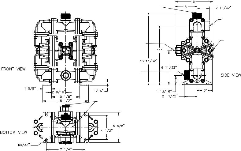
Dimensions: S07 Non-Metallic
Dimensions in Inches
Dimensional tolerance: ±1/8"
*Discharge Port |
|
¾" NPT (Internal) |
|
1½" NPT (External) |
|
Standard |
|
Encapsulated Muffler: |
|
3/8" NPT Exhaust Port |
|
For Optional Muffler |
|
Styles or Piping Exhaust |
|
Air in Submerged |
|
Applications. |
|
*Suction Port |
|
¾" NPT (Internal) |
|
1½" NPT (External) |
|
Bolt Pattern |
|
is Symmetrical |
*Both Suction and Discharge |
About Centerlines |
Ports are Available In: |
|
¾" BSPT (Tapered) (Internal) |
|
1½" BSPT (Tapered) (External) |
Manifold Can Rotate 90°
From Vertical Centerline.
Air Inlet ¼" NPT
Dimension |
A |
B |
Standard Pump |
4 1/16" |
7 1/16" |
Pulse Output Kit |
4 1/16" |
7 1/16" |
Mesh Muffler |
5 3/4" |
9 15/16" |
s07nmdl1sm-rev0614 |
Models S07 Non-Metallic Page 5 |

Metric Dimensions: S07 Non-Metallic
Dimensions in Millimeters
Dimensional tolerance: ±3mm
*Discharge Port |
|
¾" NPT (Internal) |
|
1½" NPT (External) |
|
|
Manifold can Rotate 90° |
|
From Vertical Centerline. |
Standard |
|
Encapsulated Muffler: |
Air Inlet |
3/8" NPT Exhaust Port |
|
For Optional Muffler |
¼" NPT |
Styles or Piping Exhaust |
|
Air in Submerged |
|
Applications. |
|
*Suction Port |
|
¾" NPT (Internal) |
|
1½" NPT (External) |
|
Bolt Pattern |
|
Is Symmetrical |
|
About Centerlines |
|
*Both Suction and Discharge Ports are Available In:
¾" BSPT (Tapered) (Internal) 1½" BSPT (Tapered) (External)
R5/32" |
Dimension |
A |
B |
4 Places |
Standard Pump |
103mm |
179mm |
|
Pulse Output Kit |
103mm |
224mm |
|
Mesh Muffler |
146mm |
222mm |
s07nmdl1sm-rev0614 |
Models S07 Non-Metallic Page 6 |
PRINCIPLE OF PUMP OPERATION
This ball type check valve pump is powered by compressed air and is a 1:1 ratio design. The inner side of one diaphragm chamber is alternately pressurized while simultaneously exhausting the other inner chamber. This causes the diaphragms, which are connected by a common rod secured by plates to the centers of the diaphragms, to move in a reciprocating action. (As one diaphragm performs the discharge stroke the other diaphragm is pulled to perform the suction stroke in the opposite chamber.) Air pressure is applied over the entire inner surface of thediaphragmwhileliquidisdischarged fromtheoppositesideofthediaphragm. The diaphragm operates in a balanced condition during the discharge stroke which allows the pump to be operated at discharge heads over 200 feet (61 meters) of water.
For maximum diaphragm life, keep the pump as close to the liquid being pumped as possible. Positive suction head in excess of 10 feet of liquid (3.048 meters) may require a back pressure regulating device to maximize diaphragm life.
Alternate pressurizing and exhausting of the diaphragm chamber is performed by an externally mounted, pilot operated, four way spool type air distribution valve. When the spool shifts to one end of the valve body, inlet pressure is applied to one diaphragm chamber and the other diaphragm chamber exhausts. When the spool shifts to the opposite end of the valve
body, the pressure to the chambers is reversed. The air distribution valve spool is moved by a internal pilot valve which alternately pressurizes one end of the air distribution valve spool while exhaustingthe other end.Thepilot valve is shifted at each end of the diaphragm stroke when a actuator plunger is contacted by the diaphragm plate. This actuator plunger then pushes the end of the pilot valve spool into position to activate the air distribution valve.
The chambers are connected with manifolds with a suction and discharge check valve for each chamber, maintaining flow in one direction through the pump.
INSTALLATION AND START-UP
Locate the pump as close to the product being pumped as possible. Keep the suction line length and number of fittings to a minimum. Do not reduce the suction line diameter.
For installations of rigid piping, short sections of flexible hose should be installed between the pump and the piping. The flexible hose reduces vibration and strain to the pumping system. A surge suppressor is recommended to further reduce pulsation in flow.
AIR SUPPLY
Air supply pressure cannot exceed 100 psi (7 bar). Connect the pump air inlet to an air supply of sufficient capacity and pressure required for desired performance. When the air supply line is solid piping, use a short length of flexible hose not less than
1/2" (13mm) in diameter between the pump and the piping to reduce strain to the piping. The weight of the air supply line, regulators and filters must be supported by some means other than the air inlet cap. Failure to provide support for the piping may result in damage to the pump. A pressure regulating valve should be installed to insure air supply pressure does not exceed recommended limits.
AIR VALVE LUBRICATION
The air distribution valve and the pilot valve are designed to operate WITHOUT lubrication. This is the preferred mode of operation.There may be instances of personal preference or poor quality air supplies when lubrication of the compressed air supply is required.The pump air system will operate with properly lubricated compressed air supply. Proper lubrication requires the use of an air line lubricator (available from Warren Rupp) set to deliver one drop of SAE 10 nondetergent oil for every 20 SCFM (9.4 liters/sec.) of air the pump consumes at the point of operation. Consult the pump’s published Performance Curve to determine this.
AIR LINE MOISTURE
Water in the compressed air supply can create problems such as icing or freezing of the exhaust air, causing the pump to cycle erratically or stop operating. Water in the air supply can be reduced by using a point-of-use air dryer to supplement the user’s air drying equipment. This device removes
water from the compressed air supply and alleviates the icing or freezing problems.
AIR INLET AND PRIMING
To start the pump, open the air valve approximately 1/2" to 3/4" turn. After the pump primes, the air valve can be opened to increase air flow as desired. If opening the valve increases cycling rate, but does not increase the rate of flow, cavitation has occurred. The valve should be closed slightly to obtain the most efficient air flow to pump flow ratio.
BETWEEN USES
When the pump is used for materials that tend to settle out or solidify when not in motion, the pump should be flushed after each use to prevent damage. (Product remaining in the pump between uses could dry out or settle out. This could cause problems with the diaphragms and check valves at restart.) In freezing temperatures the pump must be completely drained between uses in all cases.
s07nmdl1sm-rev0614 |
Models S07 Non-Metallic Page 7 |
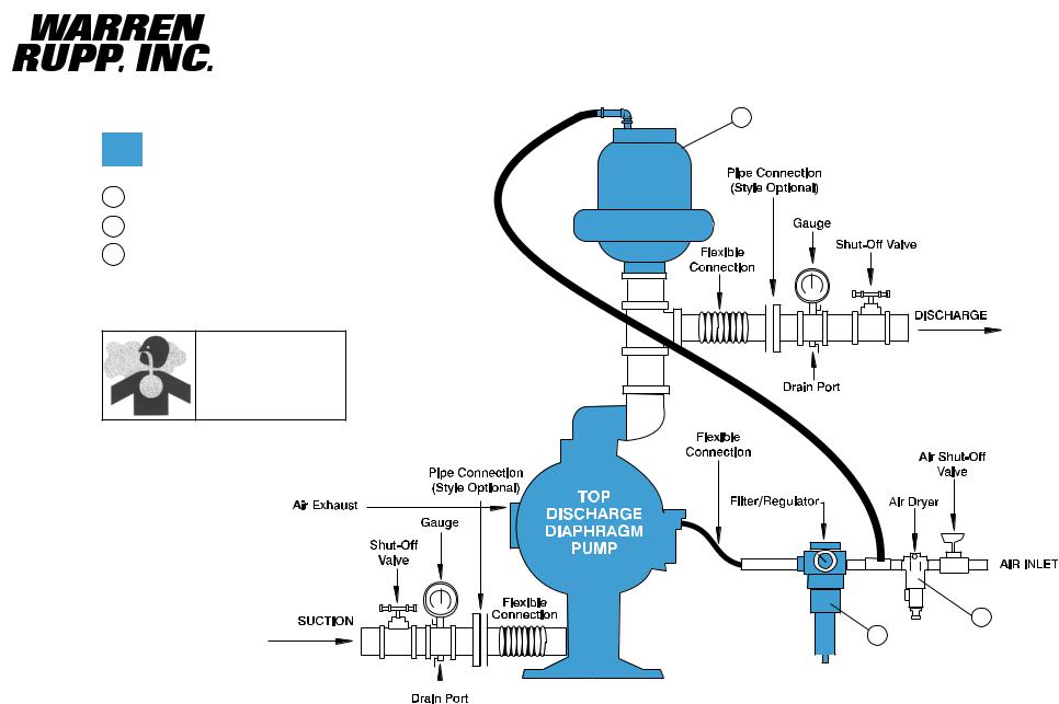
INSTALLATION GUIDE
Top Discharge Ball Valve Unit
Available from
Warren Rupp
1DA07 Surge Dampener
2020-049-000 Filter/Regulator
3Air Dryer
CAUTION
air exhaust should be piped to an area for safe disposition of the product being pumped, in the event of a diaphragm failure.
1
Surge
Dampener
Limited to
100 psi
3 |
2
|
|
|
|
|
|
|
|
|
|
|
|
|
|
|
|
|
|
|
|
|
|
|
|
|
|
|
|
|
|
|
|
|
|
|
|
|
|
|
|
|
|
|
|
|
|
|
|
|
s07nmdl1sm-rev0614 |
|
|
|
|
|
Models S07 Non-Metallic Page 8 |
TROUBLESHOOTING
Possible Symptoms:
•Pump will not cycle.
•Pump cycles, but produces no flow.
•Pump cycles, but flow rate is unsatisfactory.
•Pump cycle seems unbalanced.
•Pump cycle seems to produce excessive vibration.
What to Check: Excessive suction lift in system.
Corrective Action: For lifts exceeding 20 feet (6 meters), filling the pumping chambers with liquid will prime the pump in most cases.
What to Check: Excessive flooded suction in system.
Corrective Action: For flooded conditions exceeding 10 feet (3 meters) of liquid, install a back pressure device.
What to Check: System head exceeds air supply pressure.
Corrective Action: Increase the inlet air pressure to the pump. Most diaphragm pumps are designed for 1:1 pressure ratio at zero flow.
What to Check: Air supply pressure or volume exceeds system head.
Corrective Action: Decrease inlet air pressure and volume to the pump as calculated on the published PERFORMANCE CURVE. Pump is cavitating the fluid by fast cycling.
What to Check: Undersized suction line.
Corrective Action: Meet or exceed pump connection recommendations shown on the DIMENSIONAL DRAWING.
What to Check: Restricted or undersized air line.
Corrective Action: Install a larger air line and connection. Refer to air inlet recommendations shown in your pump’s SERVICE MANUAL.
What to Check: Check ESADS, the Externally Serviceable Air Distribution System of the pump.
Corrective Action: Disassemble and inspect the main air distribution valve, pilot valve and pilot valve actuators. Refer to the parts drawing and air valve section of the SERVICE MANUAL. Check for clogged discharge or closed valve before reassembly.
What to Check: Rigid pipe connections to pump.
Corrective Action: Install flexible connectors and a surge suppressor.
What to Check: Blocked air exhaust muffler.
Corrective Action: Remove muffler screen, clean or de-ice and reinstall. Refer to theAir Exhaust section of your pump SERVICE MANUAL.
What to Check: Pumped fluid in air exhaust muffler.
Corrective Action: Disassemble pump chambers. Inspect for diaphragm rupture or loose diaphragm plate assembly. Refer to the Diaphragm Replacement section of your pump SERVICE MANUAL.
What to Check: Suction side air leakage or air in product.
Corrective Action: Visually inspect all suction side gaskets and pipe connections.
What to Check: Obstructed check valve.
Corrective Action: Disassemble the wet end of the pump and manually dislodge obstruction in the check valve pocket. Refer to the Check Valve section of the pump SERVICE MANUAL for disassembly instructions.
What to Check: Worn or misaligned check valve or check valve seat.
Corrective Action: Inspect check valves and seats for wear and proper seating. Replace if necessary. Refer to Check Valve section of the pump SERVICE MANUAL for disassembly instructions.
What to Check: Blocked suction line.
Corrective Action: Remove or flush obstruction. Check and clear all suction screens and strainers.
What to Check: Blocked discharge line.
Corrective Action: Check for obstruction or closed discharge line valves.
What to Check: Blocked pumping chamber.
Corrective Action: Disassemble and inspect the wetted chambers of the pump. Remove or flush any obstructions. Refer to the pump SERVICE MANUAL for disassembly instructions.
What to Check: Entrained air or vapor lock in one or both pumping chambers.
Corrective Action: Purge chambers through tapped chamber vent plugs. PURGING THE CHAMBERS OF AIR CAN BE DANGEROUS! Contact the Warren Rupp Technical Service Team before performing this procedure. A model with top-ported discharge will reduce or eliminate problems with entrained air.
If your pump continues to perform below your expectations, contact your local Warren Rupp Distributor or factory Technical Service Team for a service evaluation.
WARRANTY
Refer to the enclosed Warren Rupp Warranty Certificate.
s07nmdl1sm-rev0614 |
Models S07 Non-Metallic Page 9 |
 Loading...