


SERVICE & OPERATING MANUAL
Original Instructions
Certified Quality
Quality System
ISO 9001 Certified
Environmental Management System
ISO 14001 Certified
Certified to CSA Technical Letter No, R-14
Certified to ANSI LC6-2008
Warren Rupp, Inc.
A Unit of IDEX Corporation
800 N. Main St.,
Mansfield, Ohio 44902 USA
Telephone 419.524.8388
Fax 419.522.7867
SANDPIPERPUMP.COM
Model G20
Metallic
Design Level 1
Natural Gas-Operated
Diaphragm Pumps
© Copyright 2014 Warren Rupp, Inc.
All rights reserved
3: EXP VIEW 2: INSTAL & OP 1: PUMP SPECS
4: Gas END
7: WARRANTY 6: OPTIONAL 5: WET END
sandpiperpump .com
Safety Information
 IMPORTANT
Read the safety warnings and instructions in this manual before pump installation and start-up. Failure to comply with the recommendations stated in this manual could damage the pump and void factory warranty.
When the pump is used for materials that tend to settle out or solidify, the pump should be flushed after each use to prevent damage. In freezing temperatures the pump should be completely drained between uses.
 CAUTION
Before pump operation, inspect all fasteners for loosening caused by gasket creep. Retighten loose fasteners to prevent leakage. Follow recommended torques stated in this manual.
Nonmetallic pumps and plastic components are not UV stabilized. Ultraviolet radiation can damage these parts and negatively affect material properties. Do not expose to UV light for extended periods of time.
 WARNING
When used for toxic or aggressive fluids, the pump should always be flushed clean prior to disassembly.
Before maintenance or repair, shut off the compressed gas line, bleed the pressure, and disconnect the gas line from the pump. Be certain that approved eye protection and protective clothing are worn at all times. Failure to follow these recommendations may result in serious injury or death.
Gasborne particles and loud noise hazards. Wear eye and ear protection.
In the event of diaphragm rupture, pumped material may enter the gas end of the pump, and be discharged into the atmosphere. If pumping a product that is hazardous or toxic, the gas exhaust must be piped to an appropriate area for safe containment.
Take action to prevent static sparking. Fire or explosion can result, especially when handling flammable liquids. The pump, piping, valves, containers and other miscellaneous equipment must be properly grounded.
This pump is pressurized internally with gas pressure during operation. Make certain that all fasteners are in good condition and are reinstalled properly during reassembly.
Use safe practices when lifting
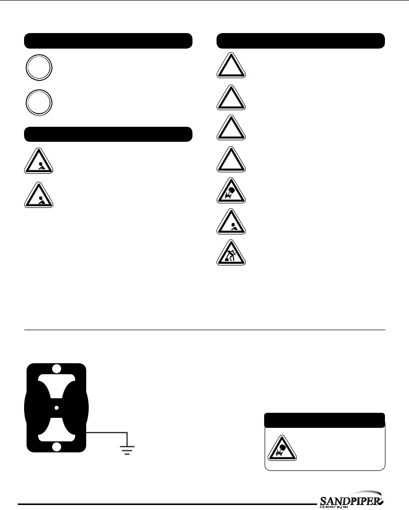
Grounding the Pump
To be fully groundable, the pumps must be ATEX Compliant. Refer to the nomenclature page for ordering information.
Optional 8 foot long (244 centimeters) Ground Strap is available for easy ground connection.
To reduce the risk of static electrical sparking, this pump must be grounded. Check the local electrical code for detailed grounding instruction and the type of equipment required.
Refer to nomenclature page for ordering information.
 WARNING
Take action to prevent static sparking. Fire or explosion can result, especially when handling flammable liquids. The pump, piping, valves, containers or other miscellaneous equipment must be grounded.
sandpiperpump.com
g20mdl1sm-rev0614

Table of Contents
SECTION 1: PUMP SPECIFICATIONS................ |
1 |
•Explanation of Nomenclature
•Performance
•Materials
•Dimensional Drawings
SECTION 2: INSTALLATION & OPERATION......5
•Principle of Pump Operation
•Recommended Installation Guide
•Troubleshooting Guide
SECTION 3: EXPLODED VIEW........................... |
8 |
•Composite Repair Parts Drawing
•Composite Repair Parts List
•Material Codes
SECTION 4: GAS END...................................... |
11 |
•Aluminum Gas Valve Assembly
•Stainless Steel Gas Valve Assembly
•Pilot Valve Assembly
•Intermediate Assembly
SECTION 5: WET END...................................... |
14 |
•Diaphragm Drawings
•Diaphragm Servicing
•Pumping Hazardous Liquids
SECTION 7: WARRANTY & CERTIFICATES.....17
•Warranty
•CE Declaration of Conformity - Machinery
•ATEX Declaration of Conformity
•ATEX Summary of Markings
sandpiperpump.com
3: EXP VIEW 2: INSTAL & OP 1: PUMP SPECS
4: AIR END
7: WARRANTY 6: OPTIONAL 5: WET END
g20mdl1sm-rev0614

1: PUMP SPECS
Explanation of Pump Nomenclature
Your Model #: |
G |
|
____ |
|
|
__ |
|
|
__ |
|
|
__ |
|
|
__ |
|
|
__ |
|
|
__ |
|
|
__ |
|
|
__ |
|
|
__ |
|
|
____ |
|
||||||||||||
(fill in from pump |
|
|
|
|
|
|
|
|
|
|
|
|
|
|
|
|
|
|
|
|
|
|
|
|
|
|
|
|
|
|
|
|
|
|
|
|
|
|
|
|
|
|
|
|
|
|
nameplate) |
|
|
|
|
|
|
|
|
|
|
|
|
|
|
|
|
|
|
|
|
|
|
|
|
|
|
|
|
|
|
|
|
|
|
|
|
|
|
|
|
|
|
|
|
|
|
|
|
|
|
|
|
|
|
|
|
|
|
|
|
|
|
|
|
|
|
|
|
|
|
|
|
|
|
|
|
|
|
|
|
|
|
|
|
|
|
|
|
|
|
|
|
|
|
Pump |
|
Pump |
Check |
Design |
Wetted |
Diaphragm/ |
Check Valve |
Non-Wetted |
Porting |
Pump |
Muffler |
|
Pump |
||||||||||||||||||||||||||||||||
|
Brand |
|
Size |
Valve |
Level |
Material |
Check Valve |
Seat |
Material |
Options |
Style |
Options |
Options |
|||||||||||||||||||||||||||||||||
|
|
|
|
|
|
|
|
|
|
|
|
|
|
|
|
|
|
|
|
|
|
|
|
|
|
|
|
|
|
|
|
|
|
|
|
|
|
|
|
|
|
|
|
|
|
|
Model #: G |
|
XX |
X |
X |
X |
X |
X |
X |
X |
X |
X |
|
XX |
|||||||||||||||||||||||||||||||||
Pump Brand
G Gas Operated
Pump Size
20 2"
Check Valve Type
B Ball
Design Level
1 Design Level
Wetted Material
S Stainless Steel A Aluminum
Diaphragm/Check Valve Materials
B |
Nitrile/Nitrile |
T |
PTFE -Nitrile/PTFE |
5 |
Nitrile/PTFE |
Check Valve Seat
B |
Nitrile |
T |
PTFE |
A |
Aluminum |
S |
Stainless Steel |
Non-Wetted Material Options
APainted Aluminum
BUnpainted Aluminum with Stainless Steel Gas Valve
D Unpainted Aluminum with Stainless Steel Gas Valve with FKM O-rings X Unpainted Aluminum
0 Unpainted Aluminum/FKM Elastomers
V Unpainted Aluminum/FKM Elastomers
SStainless Steel/ S02/304 SS Hardware
TStainless Steel/ 316 Stainless Hardware 7 Painted Stainless Steel
8 Stainless Steel/FKM Elastomers
9 Painted Stainless Steel/FKM Elastomers
Porting Options
N NPT Threads
B BSP (Tapered) Threads
R 150# Raised Face 2" ANSI Flange w/ Threaded Pipe Connections W 150# Welded Raised Face 2" ANSI Flanged Manifolds
Pump Style
S Standard
Muffler Options
X No Muffler Permitted *
Your Serial #: (fill in from pump nameplate)_ _____________________________________
ATEX Detail
II1G c T5
(1)II t G c T5
II1D c T100°C †
IM1 c
IM2 c
Models equipped with Wetted Option S Non-Wetted Options S, T, 7, 8, or 9, Pump Option X.
Note:See ATEX Explanation of EC-Type Certificate
II2G c T5
(2)II 3/2 G c T5
II2D c T100°C †
Models equipped with Wetted Options A or S, All Non-Wetted Options, Pump Option X.
Note:See ATEX Explanation of Type Examination Certificate
1• Model G20 Metallic |
sandpiperpump.com |
g20mdl1sm-rev0614

Performance
G20 METALLIC
SUCTION/DISCHARGE PORT SIZE
• 2"
CAPACITY
•0 to 150 gallons per minute (0 to 567 liters per minute)
GAS DISTRIBUTION VALVE
• No-lube, no-stall design
SOLIDS-HANDLING
• Up to .25 in. (6mm)
HEADS UP TO
•100 psi or 231 ft. of water (7 bar or 70 meters)
MAXIMUM OPERATING PRESSURE
• 100 psi (7 bar)
DISPLACEMENT/STROKE
• .42 Gallon / 1.59 liter
SHIPPING WEIGHT
•Aluminum 69 lbs. (31kg)
•Stainless Steel 114 lbs. (52kg)
These pump models are designed to pump the following fluids:
Crude Oil, Salt Water, Drilling Mud, Condensate, Lubrication Oils, Glycol, Caustic Liquids, and Acids.”
HEAD
PSI
BAR
7 100
90
6
80
5 70
460
50
3 |
40 |
|
|
2 |
30 |
|
20 |
1 |
10 |
|
|
0 |
00 |
|
|
|
|
|
|
|
|
|
|
|
|
|
|
|
|
|
MODEL G20 Metallic Performance Curve |
|
|||||||||||||||||||||
|
|
|
|
|
|
|
|
Performance based on the following: elastomer fitted pump, flooded suction, water at ambient conditions. |
|
||||||||||||||||||||||||||||||
|
|
|
|
|
|
|
|
|
|
The use of other materials and varying hydraulic conditions may result in deviations in excess of 5%. |
|
||||||||||||||||||||||||||||
20 (34) |
|
|
|
|
|
|
|
|
|
|
|
|
|
|
|
|
|
|
|
|
|
|
|
|
|
|
|
|
|
|
|
|
|
|
|||||
100 |
PSI |
|
|
40 (68) |
|
|
|
|
|
|
|
|
|
|
|
|
|
|
|
|
|
|
|
|
|
|
|
|
|
|
|
||||||||
|
|
|
|
|
|
|
|
|
|
|
|
|
|
|
|
|
|
|
|
|
|
|
|
|
|
|
|
|
|
|
|
||||||||
|
|
|
(6 |
. |
|
|
|
|
|
|
|
|
|
|
|
|
|
|
|
|
|
|
|
|
|
|
|
|
|
|
|
|
|
|
|
||||
|
|
|
|
|
|
|
|
|
|
|
|
|
|
|
|
|
|
|
|
|
|
|
|
|
|
|
|
|
|
|
|
|
|
|
|
|
|||
|
|
|
|
|
|
|
|
8 |
Bar) |
|
60 (102) |
|
|
|
|
|
|
|
|
|
|
|
|
|
|
|
|
|
|
|
|
|
|
|
|||||
|
|
|
|
|
|
|
|
|
|
|
|
|
|
|
|
|
|
|
|
|
|
|
|
|
|
|
|
|
|
|
|
|
|||||||
|
|
|
|
|
|
|
|
|
|
|
|
|
|
|
|
|
|
|
|
|
|
|
|
|
|
|
|
|
|
|
|
|
|
|
|
|
|||
80 |
PSI |
(5. |
|
|
|
|
|
|
|
|
|
|
|
|
|
|
|
|
|
|
|
|
|
|
|
|
|
|
|
|
NPSHR |
|
|||||||
|
|
|
|
|
|
|
|
|
|
|
80 (136) |
|
|
|
|
|
|
|
|
|
|
|
|
|
|
|
|
|
|||||||||||
|
|
|
|
|
|
|
|
|
|
|
|
|
|
|
|
|
|
|
|
|
|
|
|
|
|
|
|
|
|
||||||||||
|
|
|
|
|
|
|
|
|
|
|
|
|
|
|
|
|
|
|
|
|
|
|
|
|
|
|
|
|
|
|
|
|
|||||||
|
|
|
|
|
|
44 |
Bar) |
|
|
|
|
|
|
|
|
|
|
|
|
|
|
|
|
|
|
|
|
|
|
|
|
||||||||
|
|
|
|
|
|
|
|
|
|
|
|
|
|
|
|
|
|
|
|
|
|
|
|
|
|
|
|
|
|
|
|
|
|
|
|
|
|||
60 |
PSI (4. |
|
|
|
|
|
|
|
|
|
|
|
|
|
|
|
|
|
|
|
|
|
|
|
|
|
|
|
|
|
|
METERS |
|||||||
|
|
|
|
|
|
|
|
|
|
|
|
|
|
|
|
|
|
|
|
|
|
|
|
|
|
|
|
|
|
|
|
||||||||
|
|
|
|
|
|
|
|
08 |
|
Bar) |
|
|
|
|
|
|
|
|
|
100 (170) |
|
|
|
|
|
|
|
|
|
|
|
FEET |
|||||||
|
|
|
|
|
|
|
|
|
|
|
|
|
|
|
|
|
|
|
|
|
|
|
|
|
|
|
|
|
|
|
|||||||||
|
|
|
|
|
|
|
|
|
|
|
|
|
|
|
|
|
|
|
|
|
|
|
|
|
|
|
|
|
|
|
|
|
|
||||||
|
|
|
|
|
|
|
|
|
|
|
|
|
|
|
|
|
|
|
|
|
|
|
|
|
|
|
|
|
|
|
|
|
|
|
|
|
|||
40 |
|
PSI |
|
(2.72 |
Bar) |
|
|
|
|
|
|
|
|
|
|
|
|
|
|
|
|
|
|
|
|
|
|
|
|
|
|
||||||||
|
|
|
|
|
|
|
|
|
|
|
|
|
|
|
|
|
|
|
|
|
|
|
|
|
|
|
30 |
|
9.1 |
||||||||||
|
|
|
|
|
|
|
|
|
|
|
|
|
|
|
|
|
|
|
|
|
|
|
|
|
|
|
|
|
|
||||||||||
|
|
|
|
|
|
|
|
|
|
|
|
|
) |
|
|
|
|
|
|
|
|
|
|
|
|
|
|
|
|
|
|
|
|
|
|
|
25 |
|
7.6 |
20 |
PSI |
|
|
|
|
|
|
|
|
|
|
|
|
|
|
|
|
|
|
|
|
|
|
|
|
|
|
|
|
|
|
|
|
20 |
|
6 |
|||
|
|
|
|
|
|
|
|
|
|
|
|
|
|
|
|
|
|
|
|
|
|
|
|
|
|
|
|
|
|
|
|
|
|||||||
|
(1.36 |
Bar |
|
|
|
|
|
|
|
|
|
|
|
|
|
|
|
|
|
|
|
|
|
|
|
|
15 |
|
4.5 |
||||||||||
|
|
|
|
|
|
Gas |
|
|
|
|
|
|
|
|
|
|
|
|
|
|
|
|
|
|
|
|
|
|
10 |
|
3 |
||||||||
|
|
|
|
|
|
|
|
|
|
|
|
|
|
|
|
|
|
|
|
|
|
|
|
|
|
|
|
|
|||||||||||
|
|
|
|
|
|
|
|
|
|
|
|
|
|
|
|
|
|
|
|
|
|
|
|
|
|
|
|
|
|
|
|
|
|
||||||
|
|
|
|
|
|
|
|
|
|
|
|
|
|
Inlet |
|
|
|
|
|
|
|
|
|
|
|
|
|
|
|
|
|
|
|
|
5 |
|
1.5 |
||
|
|
|
|
|
|
|
|
|
|
|
|
|
|
|
Pressure |
|
|
|
|
|
|
|
|
|
|
|
|
|
|
|
|
|
|
|
|
||||
|
|
|
|
|
|
|
|
|
|
|
|
|
|
|
|
|
|
|
|
|
|
|
|
|
|
|
|
|
|
|
|
|
|
|
|
|
|
|
|
|
|
|
|
|
20 |
|
|
|
|
40 |
|
|
60 |
|
|
80 |
100 |
120 |
140 |
160 |
|
|
|||||||||||||||||
|
|
|
|
|
|
|
|
|
|
|
|
|
|
|
|
|
U.S. Gallons per minute |
|
|
|
|
|
|
|
|
|
|
|
|
|
|
||||||||
|
|
|
|
|
|
|
|
|
|
|
|
|
|
|
|
|
|
|
|
|
|
|
|
|
|
|
|
|
|
|
|
|
|
|
|
|
|
|
|
|
|
|
|
|
|
|
|
|
|
|
|
|
|
|
|
0 |
100 |
200 |
300 |
|
|
|
|
|
|
400 |
500 |
600 |
|||||||||||||||||||||||||||||||||||||||||||
|
|
|
|
|
|
|
|
|
|
|
|
|
|
|
|
|
|
|
|
|
Liters per minute |
|
|
|
|
|
|
|
|
|
|
|
|
|
|
|
|
|
|
|
|
|
|||||||||||||
CAPACITY
Exhaust Gas: The exhausted natural gas must be vented to a low pressure safe location in accordance with local fire safety and environmental codes, or in the absence of local codes, an industry or nationally recognized code having jurisdiction over the specific installations, and/or CAN/CGA B149, Installation Codes
1: PUMP SPECS
Materials
Material Profile: |
Operating |
|
CAUTION! Operating temperature limitations are as follows: |
Temperatures: |
|
Max. |
Min. |
|
FKM: (Fluorocarbon) Shows good resistance to a wide range |
350°F |
-40°F |
of oils and solvents; especially all aliphatic, aromatic and |
177°C |
-40°C |
halogenated hydrocarbons, acids, animal and vegetable oils. |
|
|
Hot water or hot aqueous solutions (over 70°F(21°C)) will |
|
|
attack FKM. |
|
|
Nitrile: General purpose, oil-resistant. Shows good solvent, oil, |
190°F |
-10°F |
water and hydraulic fluid resistance. Should not be used with |
88°C |
-23°C |
highly polar solvents like acetone and MEK, ozone, chlorinated |
|
|
hydrocarbons and nitro hydrocarbons. |
|
|
Virgin PTFE: (PFA/TFE) Chemically inert, virtually impervious. |
220°F |
-35°F |
Very few chemicals are known to chemically react with PTFE; |
104°C |
-37°C |
molten alkali metals, turbulent liquid or gaseous fluorine and |
|
|
a few fluoro-chemicals such as chlorine trifluoride or oxygen |
|
|
difluoride which readily liberate free fluorine at elevated |
|
|
temperatures. |
|
|
Maximum and Minimum Temperatures are the limits for which these materials can be operated.
Temperatures coupled with pressure affect the longevity of diaphragm pump components.
Maximum life should not be expected at the extreme limits of the temperature ranges.
Metals:
Stainless Steel: Equal to or exceeding ASTM specification A743 CF-8M for corrosion resistant iron chromium, iron chromium nickel and nickel based alloy castings for general applications. Commonly referred to as 316 Stainless Steel in the pump industry.
For specific applications, always consult the Chemical Resistance Chart.
Ambient temperature range: -20°C to +40°C
Process temperature range: -20°C to +80°C for models rated as category 1 equipment -20°C to +100°C for models rated as category 2 equipment
In addition, the ambient temperature range and the process temperature range do not exceed the operating temperature range of the applied non-metallic parts as listed in the manuals of the pumps.
sandpiperpump.com |
Model G20 Metallic • 2 |
g20mdl1sm-rev0614
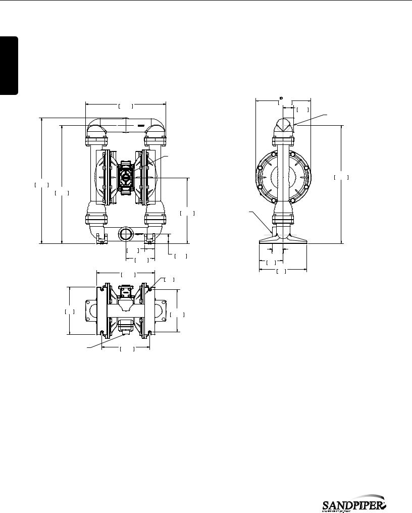
1: PUMP SPECS
Dimensional Drawings
G20 Metallic
Dimensions in inches (mm dimensions in brackets). Dimensional Tolerance:±1/8" (± 3mm)
The dimensions on this drawing are for reference only. Acertified drawing can be requested if physical dimensions are needed.
16.88 |
11.63 |
|
295.28 |
2.24 |
|
428.67 |
|
|
|
|
56.84 |
2" NPT DISCHARGE PORT
1" AIR EXHAUST PORT
24.90


 632.56 26.47


672.31 24.90
632.56
13.85 |
2" NPT SUCTION PORT |
|
351.77 |
||
|
2.19 |
|
2.25 |
55.63 |
2.00 |
57.15 |
6.12 |
50.80 |
5.00 |
155.55 |
|
|
|
127 |
|
|
|
|
12.25 |
|
10.00 |
R.25 |
254 |
|
311.15 |
|
|
|
6.35 |
|
10.00
254 9.00
228.60
3/4" NPT AIR INLET |
10.06 |
255.59 |
BOTTOM VIEW
3• Model G20 Metallic |
sandpiperpump.com |
g20mdl1sm-rev0614

Dimensional Drawings
G20 Metallic - ANSI Flange
Dimensions in inches (mm dimensions in brackets). Dimensional Tolerance:±1/8" (± 3mm)
The dimensions on this drawing are for reference only. Acertified drawing can be requested if physical dimensions are needed.
29.82
757.50
24.88
632.03
2.004X .75 HOLES
50.8019.05
13.00
330.20
16.009.00
406.40228.60
16.93
430.08
13.06
331.72
10.06
255.52
AIR INLET
3/4" NPT BOTTOM VIEW
26.38
27.88670.13
708.23
2" RF 150# ANSI FLANGE, SUCTION PORT
1" NPT EXHAUST PORT
2.00
50.80
2.19
55.56
3.00
76.20
4.00
101.60
 .50 MOUNTING HOLES 12.70
R.25
6.35
4.50
114.28
8.00
203.18
 11.63 295.28
4.87
123.70
4.99
126.69
10.00
254
7.99
202.89
16.00
406.40
5.82
147.95
2" RF 150# ANSI FLANGE DISCHARGE PORT
25.04
635.97
.67
17.07
2.00
50.80
1: PUMP SPECS
sandpiperpump.com |
Model G20 Metallic • 4 |
g20mdl1sm-rev0614
 Loading...