

Page 1

SyncMaster P2270HD,P2370HD
quick start guide
LCD TV MONITOR
Page 2

2 Installing the Product
2-1 Package Contents
• Unpack the product and check if all of the following contents have been included.
• Store the packaging box in case you need to move the product at a later stage.
CONTENTS
Quick Setup Guide Product Warranty
User Manual D-Sub Cable
(Not available in all locations)
Power Cord Batteries (AAA X 2) Stand Connector Stand
Remote Control Stereo Cable Cleaning Cloth
SOLD SEPARATELY
DVI Cable DVI Cable
The cleaning cloth is supplied with black high-glossy models only.
Installing the Product 2-1
Page 3

2-2 Installing the Stand
Before assembling the product, place the product down on a flat and stable surface so that the screen is facing downwards.
Insert the Stand Connector into the Stand Base in the direction shown by the figure.
Check if the Stand Connector is firmly connected.
Turn the connecting screw at the bottom of the stand fully so that it is completely fixed.
Place a soft cloth over the table to protect the product and place the product onto the
cloth face down.
2-2 Installing the Product
Page 4

Hold the main body of the product with your hand as shown by the figure.
Push the assembled stand into the main body in the direction of the arrow as shown in
the figure.
- Caution
Do not lift the product holding only the stand
Installing the Product 2-2
Page 5

2-3 Removing the Stand
Before removing the stand, place the product down on a flat and stable surface so that the screen faces downwards.
Place a soft cloth over the table to protect the product and place the product face down.
Hold the main body of the product with your hand as shown by the figure.
Pull the stand in the direction of the arrow as shown in the figure to separate it.
Turn the connecting screw at the bottom of the stand to separate it.
Take the Stand Connector out of the Stand by pulling it in the direction of the arrow as
shown in the figure.
2-3 Installing the Product
Page 6

2-4 Attaching a Wall Mount/Desktop Stand
Attaching a Wall Mount/Desktop Stand(not supplied)
This product provides a stand mount of 75 mm x 75 mm (2.95 x 2.95 inches) that complies with the VESA specifications.
A.Wall/Desktop Stand Mount
B.Wall mount kit/desktop stand (not supplied)
1. Turn the product off and unplug the power cord from the wall outlet.
2. Place a soft cloth or cushion on a flat surface to protect the panel and place the product face down.
3. Remove the screw from the stand and separate the stand.
4. Align the groove of the part of the product that is to be connected to the stand with the groove in the stand (desk-top stand,
wall mount stand or another stand) and firmly fix the stand by fastening the screw.
• If you use screws that are longer than the standard specifications, the inside of the product may be damaged.
• For wall mounts that are not compatible with the standard VESA specifications, the length of the screw may differ
depending on the corresponding specifications.
• Avoid using screws that are incompatible with the standard VESA specifications and avoid assembling them using
excessive force.
This may result in damage to the product or injury due to the product falling. Samsung shall not be held liable for any
damage or injury.
• Samsung shall not be held liable for any damage to the product or injury caused by using a stand that is not compatible
with the specifications or due to an installation not performed by an authorized installation engineer.
• When installing the product using a wall mount, purchase a wall mount that provides at least 10 cm (3.93 inches) of
space from the wall.
• Use the wall mount according to the international specifications.
Installing the Product 2-4
Page 7

2-5 Connecting to a Computer
1. Connect the product to a PC depending on the video output supported by the PC.
The connecting part may differ depending on the product model.
When the graphics card provides a D-Sub <analog> output
• Connect the [PC IN] port of the product to the [D-Sub] port of the PC with the D-Sub cable.
When the graphics card provides a DVI <digital> output
2-5 Installing the Product
Page 8

• Connect the [DVI-D IN] port of the product to the DVI port of the PC with the DVI cable.
2. Connect the [ HDMI/PC/DVI-D AUDIO IN] port on the rear side of the monitor to the sound card of the PC.
3. Connect one end of the power cord to the [ POWER ] port of the product and connect the other end of the power cord to the
110V or 220V wall outlet.
(The input voltage is switched automatically.)
Installing the Product 2-5
Page 9

• You may enjoy clear and quality sound from the computer sound card using the monitor's speakers. (You don't need to
install separate speakers for your computer.)
• You may get a blank screen depending on the type of video card you are using if you connect the D-sub and DVI cables
simultaneously to one computer.
• If you connect your monitor properly using the DVI connector but get a blank or fuzzy screen, check to see if the monitor
status is set to analog. Press [ ] button to have the monitor double-check the input signal source.
2-5 Installing the Product
Page 10

2-6 Using it as a TV
You may view television programs on the monitor if it is connected to an antenna or cable/satellite system without installing any
separate TV reception hardware or software on your computer.
1. Connect the cable/satellite or TV antenna cable to the [ANT IN] port on the rear side of the monitor.
• When using an indoor antenna/cable/satellite terminal:
Check the antenna terminal on the wall and then connect the antenna/cable/satellite TV cable.
• When using an outdoor antenna:
When using an outdoor antenna, we strongly suggest using a qualified technician to install it.
2. When the connections are completed, connect the TV power.
3. When the product is turned on for the first time after it was purchased, the initial setup operations (<Plug&Play>) begin.
• Be careful that the coaxial cable is not bent when connecting it to the antenna input terminal [ANT IN].
Installing the Product 2-6
Page 11

2-7 Connecting an HDMI cable
Connect the HDMI OUT port of the AV device (Blu-Ray/DVD/Cable/Satellite box) to the [HDMI IN] terminal of the monitor using
the HDMI cable.
Press the [SOURCE] button at the front of the monitor or on the remote control to select <HDMI> mode.
You do not need to make a separate audio connection when connecting via HDMI.
2-7 Installing the Product
Page 12

2-8 Connecting Using a DVI to HDMI Cable
1. Connect the DVI output terminal of an external device to the [HDMI IN] terminal of the monitor using a DVI to HDMI cable.
2. Connect the red and white plugs of an RCA to stereo (for PC) cable to the same colored audio output terminals of the digital
output device, and connect the opposite plug to the [HDMI/PC/DVI-D AUDIO IN] terminal of the product.
Press the [SOURCE] button at the front of the monitor or on the remote control to select <HDMI> mode.
Installing the Product 2-8
Page 13

2-9 Connecting a Component cable
1. Connect the VIDEO OUT port of the AV device (DVD/VCR/Cable/Satellite box) to the [COMPONENT IN [PR, PB, Y]] input ports
using a component video cable [P
, PB,Y].
R
2. Connect the audio port of the AV device (DVD/VCR/Cable/Satellite box) to the [COMPONENT IN [R-AUDIO-L]] port of the
monitor.
Press the [SOURCE] button at the front of the monitor or on the remote control to select the <Component> mode.
For an explanation of Component video, consult your DVD/VCR/Cable/Satellite box manual.
2-9 Installing the Product
Page 14
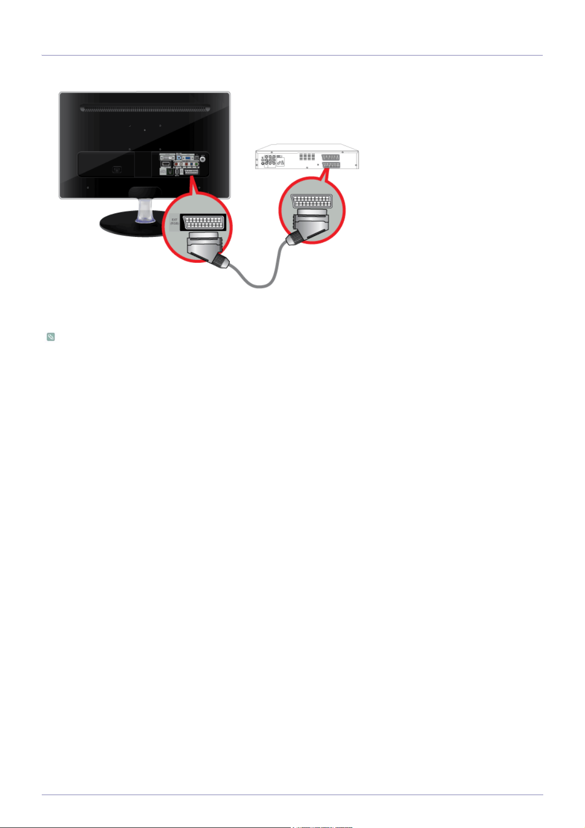
2-10 Connecting a Scart cable
1. Connect the EXT(RGB) port of the monitor to the DVD Player using a SCART jack.
2. When a Scart device is connected to your monitor, the Source automatically changes to EXT.
• Connect to the DVD Devices input if the device has a [EXT [RGB]] jack.
• You can watch DVD simply by hooking up the DVD player with the monitor as long as the power is on.
Installing the Product 2-10
Page 15

2-11 Connecting COMMON INTERFACE
1. Insert the CI CARD into the CAM in the direction of the arrow until it fits.
2. Insert the CAM with the CI CARD installed into the common interface slot.
(Insert the CAM in the direction of the arrow, right up to the end so that it is parallel with the slot.)
3. Check if you can see a picture on a scrambled signal channel.
• When not inserting ‘CI CARD’ in some channels, ‘Scrambled Signal’ is displayed on the screen.
• The pairing information containing a telephone number, CI CARD ID, Host ID and other information will be displayed in
about 2~3 minutes. If an error message is displayed, please contact your service provider.
• When the channel information configuration has finished, the message ‘Updating Completed’ is displayed, indicating
that the channel list is now updated.
• You must obtain a CI CARD from a local cable service provider. Remove the CI CARD by carefully pulling it out with
your hands since dropping the CI CARD may cause damage to it.
• Insert the CI-Card in the direction marked on it.
• CAM is not supported in some countries and regions, check with your authorized dealer.
2-11 Installing the Product
Page 16

2-12 Connecting to an Amplifier
Connect the [DIGITAL AUDIO OUT (OPTICAL)] terminal of your monitor to the optical input of your amplifier using an optical
cable.
• If no sound is emitted from the monitor, you need to use an amplifier.
• For information on how to connect a speaker and amplifier, refer to the respective user manuals provided by their
manufacturers.
Installing the Product 2-12
Page 17

2-13 Connecting Headphones
Connect your headphones to the Headphone connection terminal.
2-13 Installing the Product
Page 18

2-14 Kensington Lock
A Kensington Lock is an anti-theft device that enables users to lock the product so that they can safely use it in public locations.
Since the shape and usage of the locking device may differ depending on the model and the manufacturer, for more information,
refer to the User Manual supplied with the locking device. You have to purchase the locking device separately.
Locking the product
1. Insert the locking part of the locking device into the hole of the Kensington lock of the product ( ) and turn it in the locking
direction ( ).
2. Connect the Kensington lock cable.
3. Tie the Kensington lock cable to a desk or heavy object.
You can purchase the locking device from an electronics store or an online shop.
Installing the Product 2-14
Page 19

3 Using the Product
3-1 Plug & Play Feature
When the TV is initially powered on, basic settings proceed automatically and subsequently.
1. Press the [POWER ] button on the remote control.
• You can also use the [ ] button on the TV.
• The message <Select the OSD Language>. is displayed.
2. Press the [ ] button. Select the appropriate language by pressing the ▲ or ▼ button. Press the [ ] button to confirm your
choice.
3. Press the ◄ or ► button to select <Store Demo> or <Home Use>, then the [ ] button.
• We recommend setting the TV to <Home Use> mode for the best picture in your home environment.
• <Store Demo> mode is only intended for use in retail environments. If the unit is accidentally set to <Store Demo>
mode and you want to return to <Home Use> (Standard): Press the volume button on the TV. When the volume
OSD is displayed, press and hold the [MENU] button on the TV for 5 seconds.
4. Press the button. Select the appropriate country by pressing the ▲ or ▼ button. Press the [ ] button to confirm your
choice.
5. Press the ▲ or ▼ button to select <Air> or <Cable>, then press the [ ] button.
• <Air>: <Air> antenna signal. / <Cable>: <Cable> antenna signal.
• In Cable mode, you can select the correct signal source among <STD>, <HRC>, and <IRC> by pressing the ▲, ▼,
◄ or ► button, then press the [ ] button. If you have Digital cable, select the cable system signal source for both
Analog and Digital. Contact your local cable company to identify the type of cable system that exists in your
particular area.
6. Press the ▲ or ▼ button to select the channel source to memorize. Press the [ ] button to select <Start>.
• When setting the antenna source to <Cable>, a step appears allowing you to set a value for the digital channel
search. For more information, refer to <Channel> → <Auto Store>.
• <Digital & Analogue>: Digital and Analogue channels.
• <Digital>: Digital and Analogue channels.
• <Analogue>: Analogue channels.
• The channel search will start and end automatically.
• Press the [ ] button at any time to interrupt the memorization process.
• After all the available channels are stored, the message Set the <Clock Mode> is displayed.
7. Press the [ ] button.
Press the ▲ or ▼ button to select <Auto>, then Press the [ ] button.
• If you select <Manual>, <Set current date and time> is displayed.
• If you have received a digital signal, the time will be set automatically. If not, select <Manual> to set the clock.
3-1 Using the Product
Page 20

8. The description for the connection method providing the best HD screen quality is displayed. Check the description and press
the [ ] button.
9. The message <Enjoy your TV.> is displayed. When you have finished, press the [ ] button.
If you want to reset this feature...
1. Press the [MENU] button to display the menu. Press the ▲ or ▼ button to select <Setup>, then press the [ ] button.
2. Press the [ ] button again to select <Plug & Play>.
The <Plug & Play> feature is only available in the TV mode.
Using the Product 3-1
Page 21

3-2 Viewinig the Control panel
Touch one of the operating buttons lightly.
The LED buttons appear.
ICON DESCRIPTION
[MENU]
[ -/+ ]
[▲/▼]
[]
[]
Use this button to select a function.
Signals other than the TV signal can only be selected if the corresponding device is
connected.
The order in which the TV/external input signal changes.
<PC> → <DVI> → <TV> → <Ext.> → <Component> → <HDMI>
Press this button to view the On Screen Display (OSD).
This button is also used to exit the OSD or to return to a higher-level OSD menu.
Moves from one menu item to another horizontally or adjusts selected menu values.
Adjusts the audio volume.
Use these buttons to navigate the menu or to adjust a value in the OSD.
Press to change the channel.
Press this button to turn the product on or off.
Power LED
This LED is turned on when the product works normally.
For information about the power-saving function, refer to the power saving
function section of the product specifications. When not using the product for a
long time, unplugging the power cord is recommended to minimize power
consumption.
3-2 Using the Product
Page 22

3-3 Remote Control
The performance of the remote control may be affected by a TV or other electronic device operating near the product,
causing a malfunction due to interference with the frequency.
POWER
Turns the product On/Off.
Number Buttons
Press to change the channel.
Activates a highlighted menu item.
+ -
Press to increase or decrease the
volume.
CH LIST
It displays "Channel List" on the
screen.
MENU
Opens the on-screen menu and
exits from the menu or closes the
adjustment menu.
TOOLS
Use to quickly select frequently
used functions.
TV
Selects the TV mode directly.
PRE-CH
This button is used to return to
the immediately previous channel.
MUTE
Adjusts the audio volume.
P
Press to change channels.
SOURCE
Press the button to change the
input signal SOURCE.
Changing the SOURCE is only
allowed for external devices that
are connected to the monitor at
the time.
FAV.CH
Press to switch to your favourites
channels.
RETURN
Returns to the previous menu.
Up-Down Left-Right but-
tons ENTER
Moves from one menu item to
another horizontally, vertically or
adjusts selected menu values.
INFO
Current picture information is displayed on the upper left corner of
the screen.
COLOUR BUTTONS
Press to add or delete channels and
to store channels to the Favourite
channel list in the “Channel List”
menu.
TTX / MIX
TV channels provide written information services via teletext.
, , , , , , , ,
EXIT
Exits from the menu screen.
SUBT.
Digital subtitle display
GUIDE
Electronic Program Guide (EPG)
display.
Using the Product 3-3
Page 23

Installing Batteries in the Remote Control
1. Lift the cover at the back of the remote control upward as shown in the figure.
2. Install two AAA size batteries.
Make sure to match the +and - ends of the batteries with the diagram inside the compartment.
3. Close the cover.
Remove the batteries and store them in a cool, dry place if you won‘t be using the remote control for a long time.
If the remote control doesn‘t work, check the following :
• Is the TV power on?
• Are the plus and minus ends of the batteries reversed?
• Are the batteries drained?
• Is there a power outage or is the power cord unplugged?
• Is there a special fluorescent light or neon sign nearby?
3-3 Using the Product
Page 24

3-4 Teletext Feature
Most television stations provide written information services via Teletext. The index page of the teletext service gives
youinformation on how to use the service. In addition, you can select various options to suit your requirements by using the
remote control buttons.
For teletext information to be displayed correctly, channel reception must be stable. Otherwise, information may be missing
or some pages may not be displayed.
You can change teletext pages by pressing the numeric buttons on the remote control.
(exit)
Exit from the teletext display.
(index)
Used to display the index (contents)
page at any time while you are
viewing teletext.
(store)
Used to store the teletext pages.
(size)
Press to display the double-size letters in the upper half of the screen.
For lower half of the screen, press it
again. To display normal screen,
press it once again.
(page up)
Used to display the next teletext
page.
(page down)
Used to display the previous teletext page.
(mode)
Press to select the teletext mode
(LIST/FLOF). If you press it in the
LIST mode, it switches into the
List save mode. In the List save
mode, you can save teletext
page into list using the 8(store)
button.
(hold)
Used to hold the display on a
given page if the selected page is
linked with several secondary
pages which follow on automatically. To resume, press it again.
(reveal)
Used to display the hidden text
(answers to quiz games, for example). To display normal screen,
press it again.
(teletext on/mix)
Press to activate teletext mode after
selecting the channel providing the
teletext service. Press it twice to
overlap the teletext with the current
broadcasting screen.
(sub-page)
Used to display the available subpage.
(cancel)
Used to display the broadcast
when searching for a page.
Colour buttons (red / green / yellow / blue)
If the FASTEXT system is used
by a broadcasting company, the
different topics covered on a teletext page are colour-coded and
can be selected by pressing the
coloured buttons. Press one of
them corresponding to the
required. The page is displayed
with other coloured information
that can be selected in the same
way. To display the previous or
next page, press the corresponding coloured button.
Using the Product 3-4
Page 25

3-5 Using the Screen Adjustment Menu (OSD: On Screen Display)
The Screen Adjustment Menu (OSD: On Screen Display) Structure
TOP MENUS SUB MENUS
Picture[PC / DVI] MagicBright Contrast Brightness Sharpness Screen
Auto Adjustment Picture Options Picture Reset
Picture[TV / Ext. / Component / HDMI]
Sound Mode Equalizer SRS TruSur-
Channel Country Auto Store Manual Store Cable Search
Setup Plug & Play Language Time Game Mode Child Lock
Input Source List Edit Name
Application Anynet+ (HDMI-
Mode Backlight Contrast Brightness Sharpness
Colour Tint (G/R) Advanced Set-
tings
round HD
Audio Description
Full Guide Default Guide Channel List Channel Mode Fine Tune
Change PIN Parental Lock Subtitle Teletext Lan-
Digital Text Light Effect Light Level Melody Energy Saving
Common Interface
CEC)
Auto Volume Speaker Select Sound Reset
Picture Options Picture Reset
Audio Language
Option
guage
Audio Format
Now & Next
Guide
Preference
Support Self Diagnosis Software
Upgrade
Available Modes
The icons below represent the input signals that are displayed when selecting an item in the Source List.
Indicates the signal when <PC> or <DVI> is selected in the <Source List >.
This is the PC video signal that is connected to and input through the [PC] or [DVI] terminals.
Indicates the signal when <Ext.> is selected in the <Source List >.
This is the video signal input through the [Ext.] terminal.
Indicates the signal when <HDMI> is selected in the <Source List >.
This is the signal input through the [HDMI] terminal.
Indicates the signal when <TV> is selected in the <Source List >.
This is the signal input through the [ANT IN] terminal.
Indicates the signal when <Component> is selected in the <Source List >.
This is the signal input through the [COMPONENT] terminal.
HD Connection
Guide
Contact Samsung
3-5 Using the Product
Page 26

Picture [PC / DVI ]
The default setting may be different depending on the selected Input Mode (input signal source selected in External Input
List) and the selected resolution
MENU DESCRIPTION
MagicBright <MagicBright> is a feature providing an optimum viewing environment depending on the contents of
the image you are watching. Currently five different modes are available: <Entertain>, <Internet>,
<Text>, <Dynamic Contrast> and <Custom>. Each mode has its own pre-configured brightness
value.
•<Entertain>
High Brightness
For watching motion pictures such as a Blu-Ray or DVD.
• <Internet>
For working with a mixture of images such as texts and graphics.
• <Text>
For documents or work involving heavy text.
• <Dynamic Contrast>
<Dynamic Contrast> automatically detects the distribution of the visual signal and adjusts to
create an optimum contrast.
•<Custom>
Although the values are carefully chosen by our engineers, the pre-configured values may not be
comfortable to your eyes depending on your taste.
If this is the case, adjust the Brightness and Contrast by using the OSD menu.
Press the [TOOLS] button to display the Tools menu. You can also set the MagicBright by select-
ing <Tools> → <MagicBright>.
Contrast / Brightness /
Sharpness
You can use the on-screen menus to change the contrast and brightness according to personal preference.
• <Contrast> - Adjust the Contrast.
• <Brightness> - Adjust the Brightness.
• <Sharpness> - Adjust the Sharpness.
Auto Adjustment The values of <Fine>, <Coarse> and <Position> are adjusted automatically.
By changing the resolution in the control panel, auto function is performed.
Available in <PC> Mode Only
Press the [TOOLS] button to display the Tools menu. You can also set the auto adjustment by
selecting <Tools> → <Auto Adjustment>.
Using the Product 3-5
Page 27

MENU DESCRIPTION
Screen • <Coarse>
Removes noise such as vertical stripes.
<Coarse> adjustment may move the screen image area. You may relocate it to the center using
the horizontal control menu
• <Fine>
Removes noise such as horizontal stripes.
If the noise persists even after <Fine> tuning, repeat it after adjusting the frequency (Coarse).
• <PC Position>
Adjusts the screen location horizontally and vertically.
• <Image Reset>
Image parameters are replaced with the factory default values.
Available in <PC> Mode Only
Picture Options • <Colour Tone>
The tone of the color can be changed.
Available in <PC> / <DVI> mode only
• <Cool> - <Normal> - <Warm> - <Custom>
• <R-Gain > - < G-Gain > - <B-Gain >
Adjusts the individual R, G, B (Red, Green, Blue) color controls.
• <Size>
You can switch the Size.
•<16:9> - <4:3>
Picture Reset Picture parameters are replaced with the factory default values.
• <Reset Picture Mode> - <Cancel>
Picture [ TV / Ext. / Component / HDMI ]
3-5 Using the Product
Page 28

MENU DESCRIPTION
Mode You can select the type of picture which best corresponds to your viewing requirements.
You can activate either <Dynamic>, <Standard>, or <Movie>.
•<Dynamic>
Selects the picture for high-definition in a bright room.
• <Standard>
Selects the picture for optimum display in a normal environment.
•<Movie>
Selects the picture for viewing movies in a dark room.
Press the [TOOLS] button to display the Tools menu. You can also set the picture mode by
selecting <Tools> → <Picture Mode>.
Backlight / Contrast /
Brightness / Sharpness / Colour / Tint (G/
R)
Your product has several setting options that allow you to control the picture quality.
• <Backlight > - Adjusts the brightness of LCD back light.
• <Contrast> - Adjusts the contrast level of the picture.
• <Brightness> - Adjusts the brightness level of the picture.
• <Sharpness> - Adjusts the edge definition of the picture.
• <Colour> - Adjusts color saturation of the picture.
• <Tint (G/R)> - Adjusts the color tint of the picture.
It is activated when the signal is NTSC.
Advanced Settings Samsung‘s new TVs allow you to make even more precise picture settings than previous models.
See below to adjust detailed picture settings.
<Advanced Settings> is available in <Standard> or <Movie> mode.
• <Black Tone> - You can select the level on the screen to adjust the screen depth.
• <Off> - <Dark> - <Darker> - <Darkest>
• <Dynamic Contrast> -You can adjust the screen contrast so that the optimal contrast is provided.
• <Off> - <Low> - <Medium> - <High>
• <Gamma> - You can adjust the Primary Colour (Red, Green, Blue) Intensity.
• <Colour Space> - <Colour Space> is a color matrix composed of red, green and blue colors.
Select your Favourite <Colour Space> to experience the most natural color.
• <Auto> - <Native>
• <White Balance> - You can adjust the color temperature for more natural picture colors.
• <R-Offset> - <G-Offset> - <B-Offset> - <R-Gain> - <G-Gain> -<B-Gain> - <Reset>
• <Flesh Tone> - You can emphasize the pink <Flesh Tone> in the picture.
Changing the adjustment value will refresh the adjusted screen.
• <Edge Enhancement> - You can emphasize object boundaries in the picture.
• <Off> - <On>
Using the Product 3-5
Page 29

MENU DESCRIPTION
Picture Options • <Colour Tone>
The tone of the color can be changed.
• <Cool> - <Normal> - <Warm1> - <Warm2>
• <Warm1> or <Warm2> is only activated when the picture mode is <Movie>.
• Settings can be adjusted and stored for each external device you have connected to an
input of the TV.
• <Size>
You can switch the Size.
• <Auto Wide> - Automatically adjusts the picture size to the "16:9" aspect ratio.
• <16:9> - Adjusts the picture size to 16:9 appropriate for DVDs or wide broadcasting.
• <Wide Zoom> - Magnify the size of the picture more than 4:3.
• <Zoom> - Magnifies the 16:9 wide picture (in the vertical direction) to fit the screen size.
• <4:3> - This is the default setting for a video movie or normal broadcasting.
• <Screen Fit> - Use the function to see the original image with no cut-off with HDMI (720p/ 1080i
/ 1080p) or Component (1080i / 1080p) signals are input.
• Depending on the input source, the picture size options may vary.
• The items available may differ depending on the selected mode.
• Settings can be adjusted and stored for each external device you have connected to an
input of the TV.
• <Wide Zoom>: Press the ► button to Select Position, then press the [ ] button. Press
the ▲ or ▼ button to move the picture up/down. Then press the [ ] button.
• <Zoom>: Press the ► button to Select Position, then press the [ ] button. Press the ▲
or ▼ button to move the picture up and down. Then press the [ ] button. Press the ►
button to Select Size, then press the [ ] button. Press the ▲ or ▼ button to magnify or
reduce the picture size in the vertical direction. Then press the [ ] button.
• After selecting <Screen Fit> in HDMI (1080i) or Component (1080i) mode: Select Position
by pressing the ◄ or ► button. Use the ▲, ▼, ◄ or ► button to move the picture.
• <Reset> : Press the ◄ or ► button to select Reset, then press the [ ] button. You can
initialize the setting.
• If you use the <Screen Fit> function with HDMI 720p input, 1 line will be cut at the top,
bottom, left and right as in the Overscan function.
• <Screen Mode>
Digital Noise Reduction.
Only when setting the picture size to Auto Wide can the user determine the Screen mode. Each
individual European country requires a different picture size so this function is intended to help
users to select it.
• <16:9> - Sets the picture to 16:9 wide mode.
• <Wide Zoom> - Magnify the size of the picture more than 4:3.
• <Zoom> - Magnify the size of the picture vertically.
• <4:3> - Sets the picture to 4:3 normal mode.
This function is available in Auto Wide mode.
This function is not available in <PC>,<DVI>, <Component> or <HDMI> mode.
3-5 Using the Product
Page 30

MENU DESCRIPTION
• <Digital NR>
Digital Noise Reduction.
If the broadcast signal received by your TV is weak, you can activate the Digital Noise Reduction
feature to help reduce any static and ghosting that may appear on the screen.
• <Off> - <Low> - <Medium> - <High> - <Auto>
• <HDMI Black Level>
When a DVD or set-top box is connected to your TV via <HDMI>, it may cause a degradation in the
screen quality, such as an increase in the black level, a low contrast, or discoloration, etc.,
depending on the external device connected. In this case, adjust the screen quality of your TV by
configuring the <HDMI Black Level>.
This function is active only when the external device is connected via <HDMI>.
• <Normal> - <Low>
•<Film Mode>
The <Film Mode> feature offers you a theater-quality viewing experience.
• <Off> - <Auto>
<Film Mode> is supported in <TV>, <Component> (480i / 1080i) and <HDMI>(480i / 1080i)
Picture Reset Picture parameters are replaced with the factory default values.
• <Reset Picture Mod> - <Cancel>
Sound
Using the Product 3-5
Page 31

MENU DESCRIPTION
Mode • <Standard>
Choose Standard for the standard factory settings.
• <Music>
Choose Music when watching music videos or concerts.
•<Movie>
Choose Movie when viewing movies.
• <Clear Voice >
Emphasizes voice over other sounds.
• <Custom >
Choose Custom if you want to adjust the settings according to personal preference .
Press the [TOOLS] button to display the Tools menu. You can also set the sound mode by select-
ing <Tools> → <Sound Mode>.
Equalizer You can adjust the left and right sound balance and equalizer settings as required.
• <Mode>
You can select a sound mode to suit your personal preferences.
• <Balance>
You can adjust the left and right sound balance and equalizer settings as required.
• <100Hz> - <300Hz> - <1KHz> - <3KHz> - <10KHz>
To adjust the level of different bandwidth frequencies.
•<Reset>
Resets the equalizer settings to the default values.
SRS TruSurround HD <SRS TruSurround HD> is a patented SRS technology that solves the problem of playing 5.1 multi-
channel content over two speakers.
TruSurround delivers a compelling, virtual surround sound experience through any two-speaker playback system, including internal television speakers. It is fully compatible with all multichannel formats.
• <Off> - <On>
Press the [TOOLS] button to display the Tools menu. You can also set the picture mode by
selecting <Tools> → <SRS TruSurround HD>.
Audio Lanugage You can change the default value for audio languages. Displays the language information for the
incoming stream.
• While viewing a digital channel, this function can be selected.
• You can only select the language among the actual languages being broadcast.
Audio Format When sound is emitted from both the main speaker and the audio receiver, a sound echo may occur
due to the decoding speed difference between the main speaker and the audio receiver. In this case,
use the TV Speaker function.
• <MPEG> - <Dolby Digital>
• While viewing a digital channel, this function can be selected.
• The Audio Format appears according to the broadcasting signal.
3-5 Using the Product
Page 32

MENU DESCRIPTION
Audio Description This is an auxiliary audio function that provides an additional audio track for visually challenged per-
sons. This function handles the Audio Stream for the AD (Audio Description), when it is sent along
with the Main audio from the broadcaster. Users can turn the Audio Description On or Off and control
the volume.
• <Audio Description>
Turn the audio description function on or off.
•<Volume>
You can adjust the audio description volume.
• Volume is active when Audio Description is set to On.
• While viewing a Digital channel, this function can be selected.
Auto Volume Reduces the differences in volume level among channels.
• <Off> - <On>
Speaker Select If you want to hear the sound through separate speakers, cancel the internal amplifier.
• <External Speaker> - <TV Speaker>
• If you select <External Speaker> in the <Speaker Select> menu, the sound settings will be
limited.
• The volume and [MUTE] buttons do not operate when the <Speaker Select> is set to
<External Speaker>. Please set the volume on your Home theater.
Sound Reset You can restore the Sound settings to the factory defaults.
Channel
• <Reset All> - <Reset Sound Mode> - <Cancel>
<Reset Sound Mode>: Current sound values return to default settings.
Using the Product 3-5
Page 33

MENU DESCRIPTION
Country Select the country in which the product is being used before you use the Auto Store feature. If you do
not see your country in the list, select others.
• <Digital Channel>
You can change the country for digital channels.
• <Analogue Channel>
You can change the country for analogue channels.
The PIN number input screen appears. Enter your 4 digit PIN number.
Auto Store You can scan for the frequency ranges available to you (and availability depends on your country).
Automatically allocated programme numbers may not correspond to actual or desired programme
numbers.
If a channel is locked using the Child Lock function, the PIN input window appears.
• <Air / Cable>
Antenna source to memorize.
<Air / Cable>
• <Digital & Analogue>
Digital and Analogue channels.
• <Digital >
Digital channels.
• <Analogue >
Analogue channels.
When selecting Cable → Digital & Analogue or Cable → Digital : Provide a value to scan for
cable channels.
• <Search Mode>
Full / Network / Quick
Quick
• <Network ID>
Displays the network identification code.
• <Frequency>
Displays the frequency for the channel. (Differs in each country)
• <Modulation>
Displays available modulation values.
• <Symbol Rate>
Displays available symbol rates.
Scans for all channels with active broadcast stations and stores them in the TV`s memory.
3-5 Using the Product
Page 34

MENU DESCRIPTION
Manual Store You can scan the frequency ranges available on your television in your area and store all the chan-
nels found manually.
• <Digital Channel>
Manual store for digital channels.
• <Channel>
Set the Channel number using the ▲,▼ or number (0~9) buttons
• <Frequency>
Set the frequency using the number buttons.
• <Bandwidth>
Set the bandwidth using the ▲,▼ or number (0~9) buttons.
• Digital Channel is only available in DTV mode.
• When it has finished, channels are updated in the channel list.
• <Analogue Channel>
Manual store for analogue channel.
• <Programme> (Programme number to be assigned to a channel)
Inputting the appropriate program number on the screen. Sets the programme number using
the ▲,▼ or number (0~9) buttons
• <Colour System>
Adjusts repeatedly until the colour is of the best quality. Sets the colour system value using
the ▲ or ▼ button.
• <Auto>-<PAL>-<SECAM>-<NTSC4.43>
• <Sound System>
Adjusts repeatedly until the sound is of the best quality. Sets the sound system value using
the ▲ or ▼ button.
• <BG>-<DK>-<I>-<L>
• <Channel> (When you know the number of the channel to be stored)
You can store television channels, including those received via cable networks.
When storing channels manually, you can choose: Whether or not to store each of the
channels found. The Programme number of each stored channel which you wish to identify
• <C> (Air channel mode)
You can select a channel by entering the assigned number to each air broadcasting
station in this mode.
• <S> (Cable channel mode)
You can select a channel by entering the assigned number for each cable channel in this
mode.
• <Search> (When you do not know the channel numbers)
Press the ▲ or ▼ button to start the search. The tuner scans the frequency range until the first
channel or the channel that you selected is received on your screen.
• <Store> (When you store the channel and associated programme number)
It's used to restore the number user inputs. Set to OK by pressing the [ ] button.
Cable Search Option
(depending on the
country)
Using this function, you can manually add the channel range to be scanned by full search mode of
the Auto Store function.
• <Freq.Start~Stop>
Displays the frequency for the channel.
• <Modulation >
Displays available modulation values.
• <Symbol Rate>
Displays available symbol rates.
Using the Product 3-5
Page 35

MENU DESCRIPTION
Now & Next Guide /
Full Guide / Default
Guide
The EPG (Electronic Programme Guide) information is provided by the broadcasters. Programme
entries may appear blank or out of date as a result of the information broadcast on a given channel.
The display will dynamically update as soon as new information becomes available.
You can also display the guide menu simply by pressing the [GUIDE] button. (To configure the
<Default Guide>, refer to the descriptions.).
• <Now & Next Guide>
For the six channels indicated in the left-hand column, displays the Current programme and the
Next programme information.
• <Full Guide>
Displays the programme information as time ordered One hour segments. Two hours of
programme information is displayed which may be scrolled forwards or backwards in time.
• The programme title is on the upper part of the screen center. Please click on INFO
button for the detailed information. Channel Number, Running Time, Status Bar,
Parental Level, Video Quality Information(HD/SD), Sound Modes, Subtitle or Teletext,
Languages of Subtitle or Teletext, and brief summary of the highlighted programme are
included on the detailed information.
• “... “ will be appeared if the summary is long.
• Six channels are displayed. To scroll between channels, move to a channel using the ▲
or ▼ button.
• <Default Guide>
You can decide whether to display either the Now & Next Guide or the Full Guide when the
GUIDE button on the remote control is pressed.
• <Now & Next> - <Full Guide>
3-5 Using the Product
Page 36

MENU DESCRIPTION
Channel List Using this menu, you can Add / Delete or set Favourite channels and use the program guide for digi-
tal broadcasts.
You can select these options by simply pressing the [CH LIST] button on the remote control.
• <All Channels> - Shows all currently available channels.
• <Added Channels> - Shows all added channels.
• <Favourites> - Shows all favourite channels.
Press the [TOOLS] button to display the Tools menu. You can also set the add to (or delete
from) Favourite by selecting [Tools] → <Add to Favourite> (or <Delete from Favourite>).
To select the Favourites channels you have set up, press the [FAV.CH] button on the
remote control.
• <Programmed> - Shows all current reserved programs.
• Select a channel in the <All Channels>, <Added Channels> or <Favourites> screen by
pressing the ▲ / ▼ buttons, and pressing the [ ] button. Then you can watch the
selected channel.
• Using the Color buttons with the Channel List
• <Green> (Zoom): Enlarges or shrinks a channel number.
• <Yellow> (Select): Selects multiple channel lists. You can perform the Add / Delete
or Add to Favourite / Delete from Favourite function for multiple channels at the
same time. Select the required channels and press the yellow button to set all the
selected channels at the same time. The check mark appears to the left of the
selected channels.
• <TOOLS> (Tools): Displays the <Add> (or <Delete>), <Add to Favourite> (or
<Delete from Favourite>), <Timer Viewing>, <Edit Channel Name>, <Sort>, <Lock>,
<Select All> (or <Deselect All>) and <Auto Program> menus (The Options menus
may differ depending on the situation.)
• Channel Status Display Icons
• : An analogue channel.
• : A channel set as a Favourite.
• : A channel selected by pressing the yellow button.
• : A Program currently being broadcast.
• : A locked channel.
• : A reserved program.
Channel Mode
When press the P[ / ] button, channels will be switched within the selected channel list.
• <Added Ch.>
Channels will be switched within the memorized channel list.
• <Favourite Ch.>
Channels will be switched within the favourite channel list.
Fine Tune Use fine tuning to manually adjust a particular channel for optimal reception.
• If you do not store the fine-tuned channel in memory, adjustments are not saved.
• Fine tuned channels that have been saved are marked with an asterisk ‘*’ on the right-hand
side of the channel number in the channel banner.
• To reset the fine tuning setting, press the ▼ button to select Reset, then press the [ ]
button.
• Only Analog TV channels can be fine tuned.
Using the Product 3-5
Page 37

Setup
MENU DESCRIPTION
Plug & Play This brings up the menu items that appeared when you first plugged in the TV.
Language The language chosen affects only the language of the OSD.
Time • <Clock>
Setting the clock is necessary in order to use the various timer features of the TV.
• <Clock Mode>
You can set up the current time manually or automatically.
• <Auto> - <Manual>
• <Clock Set>
You can set the current time manually.
• The current time will appear every time you press the [INFO] button.
• If you disconnect the power cord, you have to set the clock again.
• <Sleep Timer>
The sleep timer automatically shuts off the TV after a preset time .
• <Off> - <30 min> - <60 min> - <90 min> - <120 min> - <150 min> - <180 min>
• Depending on the broadcast station and signal, the auto time may not be set
correctly. If this occurs, set the time manually.
• The Antenna or cable must be connected in order to set the time automatically.
• This function is only available when <Clock Mode> is set to <Manual>.
• You can set the day, month, year, hour and minute directly by pressing the number
buttons on the remote control.
Press the [TOOLS] button to display the Tools menu. You can also set the sleep timer by
selecting <Tools> → <Sleep Timer>.
To cancel the <Sleep Timer> function, select <Off>.
3-5 Using the Product
Page 38

MENU DESCRIPTION
• <Timer1 / Timer2 / Timer3>
Three different on / off timer settings can be made. You must set the clock first.
• <On Time>
Set the <hour>, <minute>, <am/pm>, and <activate/inactivate>.
(To activate the timer with the setting you’ve chosen, set to Activate.)
• <Off Time>
Set the <hour>, <minute>, <am/pm>, and <activate/inactivate>.
(To activate the timer with the setting you’ve chosen, set to Activate.)
•<Volume>
Set the desired volume level.
• <Antenna>
View antenna type. (<Air> or <Cable>).
You can set the Antenna by selecting <Channel> → <Antenna>.
• <Channel>
Select the desired channel.
• <Repeat>
Select <Once>, <Everyday>, <Mon~Fri>, <Mon~Sat>, <Sat~Sun> or <Manual>.
• When <Manual> is selected, press the ► button to select the desired day of the
week. Press the [ ] button over the desired day and the ( ) mark will appear.
• You can set the <hour>, <minute> and channel by pressing the number buttons on
the remote control.
• Auto Power Off
When you set the timer On, the television will eventually turn off if no controls are
operated for 3 hours after the TV was turned on by the timer. This function is only
available in timer On mode and prevents overheating, which may occur if a TV is on
for too long time.
Game Mode When connecting to a game console such as PlayStation™ or Xbox™, you can enjoy a more realistic
gaming experience by selecting game menu.
• <Off> - <On>
• Restrictions on game mode (Caution)
• To disconnect the game console and connect another external device, set <Game
Mode> to <Off> in the setup menu. If you display the TV menu in <Game mode>, the
screen shakes slightly.
• If <Game Mode> is <On> :
• Picture mode is automatically changed to <Standard> and cannot be changed.
• Sound mode is automatically changed to <Custom> and cannot be changed. Adjust the
sound using the equalizer.
• <Game Mode> is not available in regular <TV> and <PC> mode.
• If the picture is poor when external device is connected to TV, check if <Game Mode> is
<On>. Set <Game Mode> to <Off> and connect external devices.
Using the Product 3-5
Page 39

MENU DESCRIPTION
Child Lock This feature allows you to prevent unauthorized users, such as children, from watching unsuitable
programme by muting out video and audio.
• <Off>-<On>
• Before the setup screen appears, the PIN number input screen appears. Enter your 4 digit
PIN number.
• The default PIN number of a new TV set is 0-0-0-0. You can change the PIN by selecting
<Change PIN> from the menu.
• You can lock some channels in <Channel List>.
• <Child Lock> is available only in TV mode.
Change PIN You can change your personal ID number that is required to set up the TV.
• Before the setup screen appears, the PIN number input screen appears. Enter your 4digit
PIN number.
• The default PIN number of a new TV set is 0-0-0-0.
• If you forget the PIN code, press the remote control buttons in the following sequence,
which resets the PIN to 0-0-0-0: [POWER] (Off) → [MUTE] → 8 → 2 → 4 → [POWER] (On).
Parental Lock This feature allows you to prevent unauthorized users, such as children, from watching unsuitable
programme by a 4-digit PIN (Personal Identification Number) code that is defined by the user.
• <Allow All>
Press to unlock all TV ratings.
• <Block All>
Press to lock all TV ratings.
• Before the setup screen appears, the PIN number input screen appears. Enter your 4 digit
PIN number.
• The default PIN number of a new TV set is 0-0-0-0. You can change the PIN by selecting
Change PIN from the menu.
• When the parental ratings are set, the symbol is displayed.
Subtitle You can activate and deactivate the subtitles. Use this menu to set the <Mode>.
<Normal> under the menu is the basic subtitle and <Hard of hearing> is the subtitle for a hearingimpaired person.
•<Subtitle>
Switches subtitles on or off.
• <Mode>
Sets the subtitle mode.
• Normal / Hard of hearing
• <Subtitle Language>
Set the subtitle language.
• If the programme you are watching does not support the <Hard of hearing> function,
<Normal> automatically activates even though <Hard of hearing> mode is selected.
• English is the default in cases where the selected language is unavailable in the broadcast.
• You can select these options simply by pressing the [SUBT]. button on the remote control.
Teletext Language You can set the Teletext language by selecting the language type.
English is the default in cases where the selected language is unavailable in the broadcast.
3-5 Using the Product
Page 40

MENU DESCRIPTION
Preference Primary Audio Language / Secondary Audio Language / Primary Subtitle Language /Secondary Sub-
title Language / Primary Teletext Language /Secondary Teletext Language
Using this feature, users can select one of the languages. The language selected here is the default
when the user selects a channel.
If you change the language setting, the Subtitle Language, Audio Language, and the Teletext Language of the Language menu are automatically changed to the selected language.
The Subtitle Language, Audio Language, and the Teletext Language of the Language menu show a
list of languages supported by the current channel and the selection is highlighted.
If you change this language setting, the new selection is only valid for the current channel. The
changed setting does not change the setting of the Primary Subtitle Language, Primary Audio Language, or the Primary Teletext Language of the Preference menu.
Digital Text If the programme is broadcast with digital text, this feature is enabled.
• <Disable>-<Enable> (UK only)
• MHEG (Multimedia and Hypermedia Information Coding Experts Group)
• An International standard for data encoding systems used in multimedia and hypermedia.
This is at a higher level than the MPEG system which includes data-linking hypermedia
such as still images, character service, animation, graphic and video files as well as
multimedia data. MHEG is user runtime interaction technology and is being applied to
various fields including VOD (Video-On-Demand), ITV (Interactive TV), EC (Electronic
Commerce), tele-education, tele-conferencing, digital libraries and network games.
Light Effect You can turn the LED on/off on the front of monitor. You can turn it off to save power.
• <Off>
Activates the <Light Effect> (LED) only while touching the key.
•<On>
Activates the <Light Effect> (LED) only while watching the TV.
Light Level Light Level is to automatically detect distribution of inputted visual signal and adjust to create opti-
mum brightness.
The higher the number, the brighter the light of the LED emits.
Melody A melody sound can be set to come on when the monitor is powered On or Off.
• <Off> - <Low> - <Medium> - <High>
The <Melody> does not play
• When no sound is output from the TV because the [MUTE] button has been pressed.
• When no sound is output from the TV because the volume has been reduced to minimum
with the volume [-] button
• When the TV is turned off by <Sleep Timer> function
Using the Product 3-5
Page 41

MENU DESCRIPTION
Energy Saving This feature adjusts the brightness of the TV in order to reduce power consumption. When watching
TV at night, set the <Energy Saving> mode option to <High> to reduce eye fatigue as well as power
consumption.
• <Off> : Turns off the energy saving function.
• <Low> : Sets the TV to low energy saving mode.
• <Medium> : Sets the TV to medium energy saving mode.
• <High> : Sets the TV to high energy saving mode.
• <Auto> : Automatically adjusts the brightness of the TV screen in accordance with the scenes.
Common Interface • <CI Menu>
This enables the user to select from the CAM-provided menu.
Select the CI Menu based on the menu PC Card.
• <Application Info.>
This contains information on CAM inserted in the CI slot and displays it.
The Application Info inserting is about the CI CARD. You can install the CAM anytime whether the
TV is ON or OFF.
Input
MENU DESCRIPTION
Source List Use to select <PC>, <TV> or an external input source connected to the Monitor.Use to select the
screen of your choice.
You can use the [SOURCE] button on the remote control.
• <PC> - <DVI> - <TV> - <Ext.> - <Component> - <HDMI>
Edit Name Name the input device connected to the input jacks to make your input source selection easier.
<PC> - <DVI> - <Ext.> - <Component> - <HDMI>
Anynet+ (HDMI-CEC)
What is <Anynet+>?
<Anynet+> is a function that enables you to control all connected Samsung devices that support <Anynet+> with your Samsung
TV‘s remote. The <Anynet+ > system can be used only with Samsung devices that have the <Anynet+> feature. To be sure your
Samsung device has this feature, check if there is an <Anynet+> logo on it.
3-5 Using the Product
Page 42

Connecting Anynet+ Devices
1. Connect the [HDMI IN] jack on the TV and the HDMI OUT jack of the corresponding <Anynet+> device using an HDMI
cable.
2. Connect the [HDMI IN] jack of the home theatre and the HDMI OUT jack of the corresponding <Anynet+> device using an
HDMI cable.
Connect the Optical cable between the [DIGITAL AUDIO OUT (OPTICAL)] jack on your TV and the Digital Audio Input
on the Home Theatre.
When following the connection above, the Optical jack only outputs 2 channel audio. You will only hear sound from the
Home Theatre‘s Front Left and Right speakers and the subwoofer. If you want to hear 5.1 channel audio, connect the
[DIGITAL AUDIO OUT (OPTICAL)] jack on the DVD / Satellite Box (ie Anynet Device 1 or 2) directly to the Amplifier or
Home Theatre, not the TV.
Connect only one Home Theatre.
You can connect an <Anynet+> device using the HDMI 1.3 cable. Some HDMI cables may not support <Anynet+>
functions.
<Anynet+> works when the AV device supporting <Anynet+> is in the Standby or On status.
<Anynet+> supports up to 10 AV devices in total. Note that you can connect up to 3 devices of the same type.
Setting Up Anynet+
Press the [TOOLS] button to display the Tools menu. You can also display the <Anynet+> menu by selecting <Tools> →
<Anynet+ (HDMI-CEC)>
Using the Product 3-5
Page 43

Setup
• <Anynet+ (HDMI-CEC)>
To use the <Anynet+> Function, <Anynet+ (HDMI-CEC)> must be set to On.
When the <Anynet+ (HDMI-CEC) >function is disabled, all the< Anynet+> related operations are deactivated.
• <Auto Turn Off>
Setting an <Anynet+> Device to turn Off automatically when the TV is turned off.
The active source on the TV remote must be set to TV to use the <Anynet+> function.
If you set Auto Turn Off to Yes, connected external devices are also turned off when the TV is turned off. If an
external device is still recording, it may or may not turn off.
Device List
1. Press the [TOOLS] button. Press the [ ] button to select <Anynet+ (HDMI-CEC)>.
2. Press the or button to select <Device List>, then press the [ ] button.
- <Anynet+> devices connected to the TV are listed.
- If you cannot find a device you want, press the red button to scan for devices.
3. Press the or button to select a particular device and press the [ ] button. It is switched to the selected device.
- <Anynet+ (HDMI-CEC)> must be set to On in the <Application> menu for the <Device List> menu to appear.
Switching to the selected devices may take up to 2 minutes. You cannot cancel the operation during the switching
operation.
The time required to scan for devices is determined by the number of connected devices.
When the device scan is complete, the number of devices found are not displayed.
Although the TV automatically searches the device list when the TV is turned on via the power button, devices
connected to the TV may not always be automatically displayed in the device list. Press the red button to search for the
connected device.
If you have selected external input mode by pressing the [SOURCE] button, you cannot use the <Anynet+> function.
Make sure to switch to an <Anynet+> device by using the <Device List>.
3-5 Using the Product
Page 44

Support
Using the Product 3-5
Page 45

MENU DESCRIPTION
Self Diagnosis • <Picture Test>
If you think you have a picture problem, perform the picture test. Check the colour pattern on the
screen to see if the problem still exists.
• <Yes> : If the test pattern does not appear or there is noise in the test pattern, select <Yes>.
There may be a problem with the TV. Contact Samsung‘s call centre for assistance.
• <No> : If the test pattern is properly displayed, select <No>. There may be a problem with your
external equipment. Please check your connections. If the problem still persists, refer to the
external device‘s user manual.
• <Sound Test>
If you think you have a sound problem, please perform the sound test. You can check the sound by
playing a built-in melody sound through the TV.
• <Yes> : If during the sound test you can hear sound only from one speaker or not at all, select
<Yes>. There may be a problem with the TV. Contact Samsung’s call center for assistance.
• <No> : If you can hear sound from the speakers, select <No>. There may be a problem with
your external equipment. Please check your connections. If the problem still persists, refer to
the external device’s user manual.
• If you hear no sound from the TV‘s speakers, before performing the sound test, make
sure <Speaker Select > is set to <TV speaker> in the <Sound> menu.
• The melody will be heard during the test even if <Speaker Select> is set to <External
Speaker> or the sound is muted by pressing the [MUTE] button.
• <Signal Information (digital channels only)>
Unlike analogue channels, which can vary in reception quality from snowy to clear, digital (HDTV)
channels have either perfect reception quality or you will not receive them at all. So, unlike
analogue channels, you cannot fine tune a digital channel. You can, however, adjust your antenna
to improve the reception of available digital channels.
If the signal strength meter indicates that the signal is weak, physically adjust your antenna to
increase the signal strength. Continue to adjust the antenna until you find the best position
with the strongest signal.
Software Upgrade • <By USB>
Insert a USB drive containing the firmware upgrade downloaded from samsung.com into the TV.
Please be careful not to disconnect the power or remove the USB drive while upgrades are being
applied. The TV will turn off and turn on automatically after completing the firmware upgrade.
Please check the firmware version after the upgrades are complete (the new version will have a
higher number than the older version).
When software is upgraded, video and audio settings you have made will return to their default
(factory) settings. We recommend you write down your settings so that you can easily reset them
after the upgrade.
• <By Channel>
Upgrades the software using the broadcasting signal.
• <Standby Mode Upgrade>
To continue software upgrade with master power on, select on by pressing the ▲ or ▼ button. 45
minutes after entering standby mode, a manual upgrade is automatically conducted. Since the
power of the unit is turned on internally, the screen may be on slightly for the LED product. This
phenomenon may continue for more than 1 hour until the software upgrade is completed.
• <Alternative Software>(Backup)
If there is an issue with the new firmware and it is affecting operation, you can change the software
to the previous version.
• If software was changed, existing software is displayed.
• You can change current software to alternative software by ‘Alternative Software’.
3-5 Using the Product
Page 46

MENU DESCRIPTION
HD Connection Guide This menu presents the connection method that provides the optimal quality for the HDTV. Refer to
this information when connecting external devices to the TV.
Contact Samsung View this information when your TV does not work properly or when you want to upgrade the soft-
ware. You can view the information regarding the call center, product and software file download
method.
Using the Product 3-5
Page 47

3-6 Installing the Device Driver
If you install the device driver, you can set up the appropriate resolution and frequency for the product. The device driver is
included on the CD supplied with the product. If the supplied drive file is corrupted, please visit the Samsung Electronics
website (www.samsung.com), and download the driver.
1. Insert the driver installation CD into the CD-ROM drive.
2. Click on Windows Driver.
3. Select the model of your product from the model list.
4. Complete the remaining installation steps according to the instructions displayed on the screen.
5. Check if the appropriate resolution and screen refresh rate are displayed in the Control Panel settings. For more information,
refer to the document about the Windows operating system.
3-6 Using the Product
Page 48

3-7 Standard Signal Mode Table
An LCD monitor has one optimal resolution for the best visual quality depending on the screen size due to the inherent
characteristics of the panel, unlike a CDT monitor.
Therefore, the visual quality will be degraded if the optimal resolution is not set for the panel size. It is recommended setting
the resolution to the optimal resolution of the product.
If the signal from the PC is one of the following standard signal modes, the screen is set automatically. However, if the signal from
the PC is not one of the following signal modes, a blank screen may be displayed or only the Power LED may be turned on.
Therefore, configure it as follows referring to the User Manual of the graphics card.
RESOLUTION
HORIZONTAL
FREQUENCY
(KHZ)
VERTICAL
FREQUENCY
(HZ)
CLOCK
FREQUENCY
(MHZ)
POLARITY (H/V)
IBM, 640 x 350 31.469 70.086 25.175 +/-
IBM, 640 x 480 31.469 59.940 25.175 -/-
IBM, 720 x 400 31.469 70.087 28.322 -/+
MAC, 640 x 480 35.000 66.667 30.240 -/-
MAC, 832 x 624 49.726 74.551 57.284 -/-
MAC, 1152 x 870 68.681 75.062 100.000 -/-
VESA, 640 x 480 37.861 72.809 31.500 -/-
VESA, 640 x 480 37.500 75.000 31.500 -/-
VESA, 800 x 600 35.156 56.250 36.000 +/+
VESA, 800 x 600 37.879 60.317 40.000 +/+
VESA, 800 x 600 48.077 72.188 50.000 +/+
VESA, 800 x 600 46.875 75.000 49.500 +/+
VESA, 1024 x 768 48.363 60.004 65.000 -/-
VESA, 1024 x 768 56.476 70.069 75.000 -/-
VESA, 1024 x 768 60.023 75.029 78.750 +/+
VESA, 1152 x 864 67.500 75.000 108.000 +/+
VESA, 1280 X 800 49.702 59.810 83.500 +/+
VESA, 1280 X 960 60.000 60.000 108.000 +/+
VESA, 1280 X 1024 63.981 60.020 108.000 +/+
VESA, 1280 X 1024 79.976 75.025 135.000 +/+
VESA, 1440 x 900 55.935 59.887 106.500 -/+
VESA, 1600 x 1200 75.000 60.000 162.000 +/+
VESA, 1680 x 1050 65.290 59.954 146.250 -/+
VESA, 1920 x 1080 67.500 60.000 148.500 +/+
Horizontal Frequency
The time taken to scan one line from the left-most position to the right-most position on the screen is called the horizontal cycle
and the reciprocal of the horizontal cycle is called the horizontal frequency. The horizontal frequency is represented in kHz.
Vertical Frequency
A panel must display the same picture on the screen tens of times every second so that humans can see the picture. This
frequency is called the vertical frequency. The vertical frequency is represented in Hz.
Using the Product 3-7
Page 49

5 Troubleshooting
5-1 Monitor Self-Diagnosis
• You can check if the product is working properly using the Self-Diagnosis function.
• If a blank screen is displayed and the Power LED blinks even if the product and the PC are properly connected, perform
the self-diagnosis function according to the procedures below.
1. Turn the product and the PC off.
2. Remove the D-Sub cable from the product.
3. Turn the product on.
4. If the product is working properly, the 'Check cable connection' message appears.
In this case, if a blank screen is displayed again, make sure that there is no problem with the PC and the connection.
5-1 Troubleshooting
Page 50

5-2 Before Requesting Service
Please check the following before requesting After-Sales service. If the problem continues, please contact your nearest
Samsung Electronics Service Center.
PROBLEMS RELATED TO INSTALLATION (PC MODE)
The monitor screen flickers. Check if the signal cable between the computer and the monitor is securely
connected and tightened.
(Refer to Connecting to a Computer)
PROBLEMS RELATED TO SCREEN
Screen is blank and power indicator is off. Ensure that the power cord is firmly connected and the LCD monitor is on.
(Refer to Connecting to a Computer)
"Check Signal Cable” message Ensure that the signal cable is firmly connected to the PC or video sources.
(Refer to Connecting to a Computer)
"Not Optimum Mode" message Check the maximum resolution and the frequency of the video adapter.
Compare these values with the data in the Preset Timing Modes Chart.
Picture rolls vertically. Check if the signal cable is securely connected.Connect it again securely.
(Refer to Connecting to a Computer)
Image is not clear. Picture is blurred. Run Frequency <Coarse > and < Fine> tuning.
Turn on again after removing all accessories(video extension cable, etc.)
Set resolution and frequency to the recommended ranges.
Picture image is unstable and vibrates. Check if the resolution and frequency set for the computer video card falls
Ghost images are shown in the picture.
in the range supported by the monitor. If not, reset them referring to the
current <Information> under the monitor menu and Preset Timing Modes.
The image is too light or too dark Adjust the Brightness and Contrast
(Refer to the <Brightness>, <Contrast>)
Screen is blank and the power indicator light
blinks every 0.5 or 1 seconds
The monitor is using its power management system
Press a key on the keyboard
The screen is blank and is blinking. If you see the TEST GOOD message on the screen when you press the [
MENU] button, check the cable connection between the monitor and the
computer to ensure that the connector is properly connected.
PROBLEMS RELATED TO AUDIO
No sound Ensure that the audio cable is firmly connected to both the audio-in port on
your monitor and the audio-out port on your sound card.
(Refer to Connecting to a Computer)
Check the volume level.
The sound level is too low. Check the volume level.
If the volume is still too low after turning the control to its maximum, check
the volume control on the computer sound card or software program.
PROBLEMS RELATED TO REMOTE CONTROL
The remote control buttons do not respond. Check the battery polarities (+/-).
Check if the batteries have been exhausted.
Check if the power is on.
Check if the power cord is securely connected.
Check if a special fluorescent or neon lamp is on in the vicinity
Troubleshooting 5-2
Page 51

NOTE ON THE PRODUCT APPEARANCE
You may see small particles if you look closely at
the edge of the bezel surrounding the screen.
This is part of the product's design and is not a defect.
5-2 Troubleshooting
Page 52

5-3 FAQ
FAQ PLEASE TRY THE FOLLOWING!
How can I change the frequency of the video signal?
How can I change the resolution? Windows XP: Change the resolution by selecting Control Panel → Appear-
How can I use the power saving function? Windows XP: Configure it by selecting Control Panel → Appearance and
How can I clean the outer case/LCD Panel? Disconnect the power cord and then clean the monitor with a soft cloth,
You have to change the frequency of the graphics card.
(For more information, refer to the User Manual of the computer or the
graphics card.)
ance and Themes → Display → Settings.
Windows ME/2000 : Change the resolution by selecting Control Panel →
Appearance and Themes → Display → Settings.
(For more information, refer to the User Manual of the computer or the
graphics card.)
Themes → Display → Screen Saver Settingor configure it in the BIOS
SETUP of the computer.
Windows ME/2000 : Configure it by selecting Control Panel → Appearance
and Themes → Display → Screen Saver Settingor configure it in the BIOS
SETUP of the computer.
For more information, refer to the Windows user manual for the computer.
using either a plain water.
Do not leave any detergent or scratches on the case.
Do not let any water enter the monitor.
What is the difference between HDTV and
SDTV?
Can I watch HD broadcasting with all digital
TVs?
Can I watch digital TV broadcasting with an analog TV?
Can I use my present antenna to receive digital
broadcasting?
There are various types of digital TVs.
The most widely known types of digital TV are HDTV and SDTV. They are
classified according to the screen quality and the video specifications.
• HDTV (High Definition TV):High screen quality.
• SDTV (Standard Definition TV):Common standard digital TV.
An SDTV has an aspect ratio of 4:3 which is the same as that of an analog
TV. HDTV has an aspect ratio of 16:9 which is similar to a cinema screen.
This provides a much better screen quality than SDTV.
Digital TV broadcasting in our country is ultimately orientated towards
HDTV. (At present, all digital TVs from Samsung Electronics have the 16:9
wide aspect ratio.)
You can receive all digital broadcasts, whether they are SD or HD, using
any digital TV. However, you cannot enjoy HD programs, which are the
highest quality digital TV programs, using an SD digital TV.
(At present, all digital TVs from Samsung Electronics have the 16:9 wide
aspect ratio.)
No.
The analog TV cannot interpret digital signals. Therefore, a digital TV is
required to watch digital TV broadcasting.
As for existing analog TV, digital TV is designed so that digital broadcasting signals are received via both indoor and outdoor antennas.
If signal reception is very good in your environment, you can watch digital
broadcasts with your existing indoor antenna. If not, it is better to install an
outdoor antenna.
Troubleshooting 5-3
 Loading...