

SAMSUNG SVR527 Service Manual
VIDEO CASSETTE RECORDER
SVR-527
SERVICE
1. Precautions
2. Alignment and Adjustment
3. Exploded View and Parts List
4. Electrical Parts List
5. Schematic Diagrams
Manual
VIDEO CASSETTE RECORDER CONTENTS
For mechanical disassembly and adjustment, refer to the “Mechanical Manual” (DX-9R AC68-00001A).
SERVICE MANUAL SVR-527
ELECTRONICS
© Samsung Electronics Co., Ltd. APR. 1999
Printed in Korea
AC68-00292A
R
E
W
F
.
F
REC
POWER EJECT STOP
IMPORTANT SERVICE GUIDE
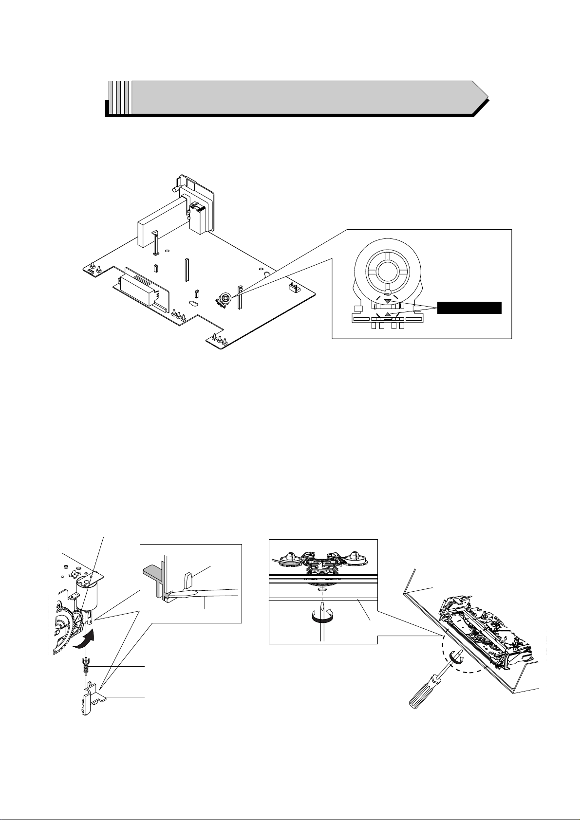
3 MODE SWITCH (PROGRAM SWITCH) ASSEMBLY POINT
1) When installing the ass’y full deck on the Main PCB, be sure to align the assembly point of mode switch.
ASSEMBLY POINT
Fig. 1
3 HOW TO EJECT THE CASSETTE TAPE
(If the unit does not operate on condition that tape is inserted into housing ass’y)
1) Remove the Holder Worm Œ and the gear worm ´. (See Fig. 2)
2) Turn the Gear Worm Wheel ˇ counterclockwise in the direction of arrow with screw driver. (See Fig. 2)
3) When Slider S, T are approached in the position of unloading, rotate holder Clutch counterclockwise after inserting screw driver in the
hole of frame’s bottom in order to wind the unwounded tape. (Refer to Fig. 3)
(If you rotate Gear Worm Wheel continuously when tape is in state of unwinding, you may cause a tape contamination by grease and
tape damage. Be sure to wind the unwounded tape in the state of set horizontally.)
4) Rotate Gear Worm Wheel ˇ counterclockwise using screw driver again up to the state of eject mode and then pick out the tape.
(Refer to Fig. 2)
Fig. 2 Fig. 3
ΠHOLDER WORM
´ GEAR WORM
SCREW DRIVER
ˇ GEAR WORM WHEEL
FRAME

Samsung Electronics 1-1
1. Precautions
1. Be sure that all of the built-in protective devices are
replaced. Restore any missing protective shields.
2. When reinstalling the chassis and its assemblies, be
sure to restore all pretective devices, including :
control knobs and compartment covers.
3. Make sure that there are no cabinet openings
through which people--particularly children
--might insert fingers and contact dangerous
voltages. Such openings include the spacing
between the picture tube and the cabinet mask,
excessively wide cabinet ventilation slots, and
improperly fitted back covers.
If the measured resistance is less than 1.0 megohm
or greater than 5.2 megohms, an abnormality exists
that must be corrected before the unit is returned
to the customer.
4. Leakage Current Hot Check (See Fig. 1-1) :
Warning : Do not use an isolation transformer
during this test. Use a leakage current tester or a
metering system that complies with American
National Standards Institute (ANSI C101.1,
Leakage Current for Appliances), and Underwriters
Laboratories (UL Publication UL1410, 59.7).
Fig. 1-1 AC Leakage Test
5. With the unit completely reassembled, plug the AC
line cord directly the power outlet. With the unitÕs
AC switch first in the ON position and then OFF,
measure the current between a known erath
ground (metal water pipe, conduit, etc.) and all
exposed metal parts, including : antennas, handle
brackets, metal cabinets, screwheads and control
shafts. The current measured should not exceed
0.5 milliamp. Reverse the power-plug prongs in the
AC outlet and repeat the test.
6. Antenna Cold Check :
With the unitÕs AC plug disconnected from the
AC source, connect an electrical jumper across the
two AC prongs. Connect one lead of the ohmmeter
to an AC prong.
Connect the other lead to the coaxial connector.
7. Some semiconductor (Òsolid stateÓ) devices are
easily damaged by static electricity.
Such components are called Electrostatically
Sensitive Devices (ESDs); examples include
integrated circuits and some field-effect transistors.
The following techniques will reduce the
occurrence of component damage caused by static
electricity.
8. Immediately before handling sny semiconductor
components or assemblies, drain the electrostatic
charge from your body by touching a known
earth ground. Alternatively, wear a discharging
Wrist-strap device. (Be sure to remove it prior to
applying power--this is an electric shock
precaution.)
9. Design Alteration Warning :
Never alter or add to the mechanical or electrical
design of this unit. Example : Do not add
auxiliary audio or video connectors.
Such alterations might create a safety hazard.
Also, any design changes or additions will void
the manufacturerÕs warranty.
10. Never defeat any of the B+ voltage interlocks.
Do not apply AC power to the unit (or any of its
assemblies) unless all solid-state heat sinks are
correctly installed.
DEVICE
UNDER
TEST
(READING SHOULD
NOT BE ABOVE
0.5mA)
LEAKAGE
CURRENT
TESTER
EARTH
GROUND
TEST ALL
EXPOSED METER
SURFACES
ALSO TEST WITH
PLUG REVERSED
(USING AC ADAPTER
PLUG AS REQUIRED)
2-WIRE CORD

Precautions
1-2 Samsung Electronics
11. Always connect a test instrumentÕs ground lead to
the instrument chassis ground before connecting
the positive lead; always remove the instrumentÕs
ground lead last.
12. Observe the original lead dress, especially near
the following areas : Antenna wiring, sharp
edges, and especially the AC and high voltage
power supplies. Always inspect for pinched, outof-place, or frayed wiring. Do not change the
spacing between components and the printed
circuit board. Check the AC power cord for
damage. Make sure that leads and components
do not touch thermally hot parts.
13. Product Safety Notice :
Some electrical and mechanical parts have special
safety-related characteristics which might not be
obvious from visual inspection. These safety
features and the protection they give might be
lost if the replacement component differs from the
original--even if the replacement is rated for
higher voltage, wattage, etc.
Components that are critical for safety are
indicated in the circuit diagram by shading,
( or ).
Use replacement components that have the same
ratings, especially for flame resistance and
dielectric strength specifications. A replacement
part that does not have the same safety
characteristics as the original might create shock,
fire or other hazards.
Samsung Electronics
2-1
2. Alignment and Adjustment
2-1 Reference
1) X-Point (Tracking center) adjustment, “Head switching adjustment” can be adjusted with remote control.
2) When replacing the Micom (IC601) and NVRAM (IC603 ; EEPROM) be sure to adjust the “Head switching adjustment”.
3) When replacing the cylinder ass’y, be sure to adjust the “X-Point” and “Head switching adjustment”.
4) Among Samsung VCR remote control used for adjustment as a accessory, only the remote control that has figures buttons (0 ~ 9) is
available for all adjustment regardless of chassis.
5) How to adjustment.
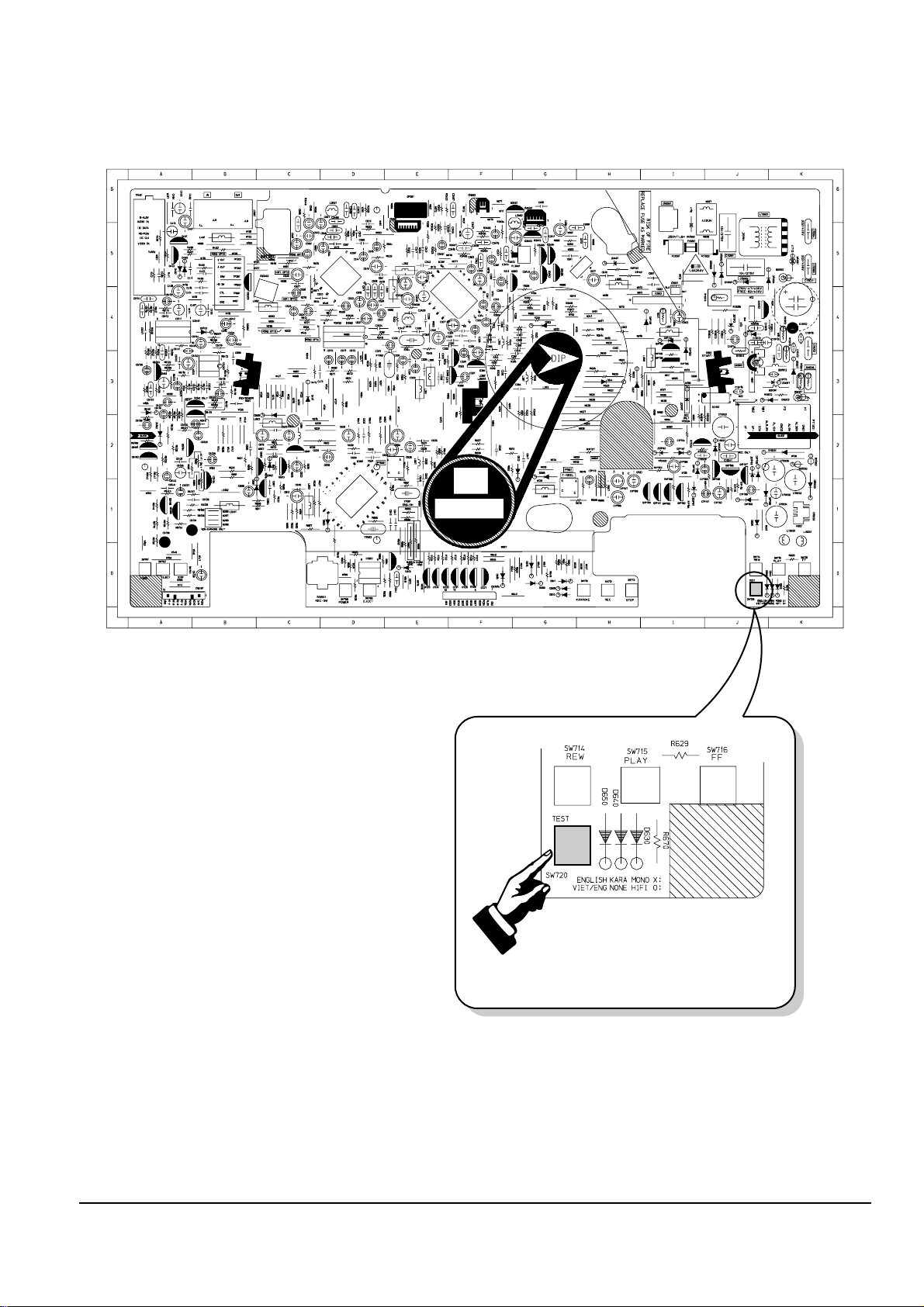
- Press the “SW720 (TEST)” button on Main PCB to set the adjustment mode.
- If the corresponding adjustment button is pressed, the adjustment is performed automatically.
- If the adjustment is completed, be sure to turn the power off.
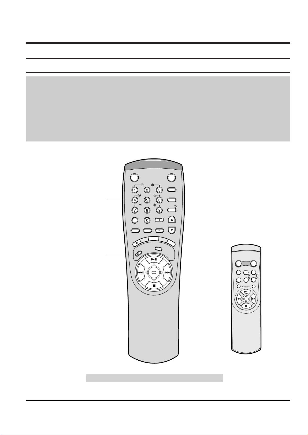
2-1-1 Location of adjustment button of remote control
Fig. 2-1
<This type of remote control can adjust.>
<This type of remote control can not adjust.>
Remote Control for adjustment is not supplied as a Service Jig.
VCR POWER TV POWER
TV
SLOW
VCR
DISP./
SHUTTLE
V-LOCK
CLR/RST F.ADV
-/--
INPUT INDEX
VOL PROG/TRK
R
E
C
M
E
N
U
A
U
D
I
O
S
P
E
E
D
T
V
/
V
C
R
REPEAT
OK
Head Switching Adjustment
("SPEED" Button)
X-Point (Tracking Center) Adjustment
("5" Button)
R
E
P
E
A
T
POWER DISPLAY
CNT.RESET
IIP/S
SLOW TRK
REC MENU
(SVR-527)
2-2
Samsung Electronics
Alignment and Adjustment
2-1-2 SW720 (TEST) location for adjustment mode setting
Fig. 2-2 Main PCB (Top View)
PRESS
Alignment and Adjustment
Samsung Electronics
2-3
2-2 Mechanical Adjustment
Note : Refer to the Mechanical Manual ÒDX-9R (AC68-00001A)Ó for the adjustment and confirmation of assÕy full deck.
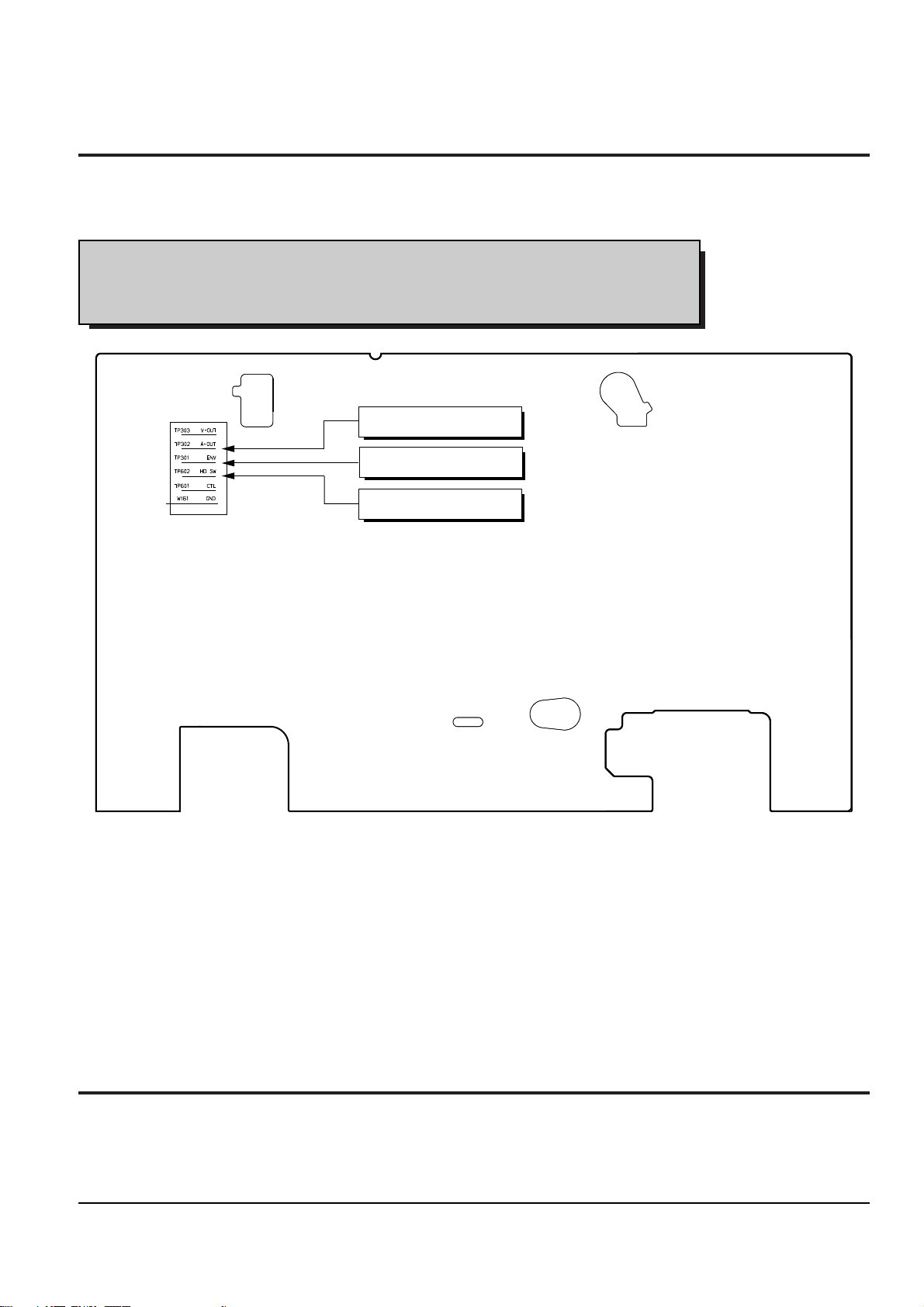
2-2-1 The number and position of test point
Test point : TP601 (Control Pulse) TP301 (Envelope)
TP602 (H’D S/W -Trigger) TP302 (Audio output)
TP303 (Video output)
Fig. 2-3 Location of Test point (Main PCB-Top View)
AUDIO OUTPUT
HEAD SWITCHING
ENVELOPE
2-2-1 ACE Head Position (X-Point) Adjustment
(See the 2-2-1(d) ACE Head Position (X-Point) Adjustment
on page 2-2 of the Mechanical Manual)
1) Playback the alignment tape (Color bar).
2) Press the ÒSW720 (TEST)Ó button on Main PCB to
set the adjustment mode. (See Fig. 2-2)
3) Press the Ò5Ó button of remote control then
adjustment is operated automatically. (See Fig. 2-1)
4) Connect the CH-1 probe to TP301 (Envelope) the
CH-2 probe to TP602 (HÕD switching pulse) and
then trigger to CH-1.
5) Insert the (-) driver into the X-Point adjustment
hole and adjust it so that envelope waveform is
maximum.
6) Turn the Power off.
2-3 Head Switching Point Adjustment
1) Playback the alignment tape.
2) Press the ÒSW720 (TEST)Ó button on Main PCB to set the adjustment mode. (See Fig. 2-2)
3) Press the ÒSPEEDÓ button of remote control then adjustment is operated automatically. (See Fig. 2-1)
4) Turn the Power off.

2-4
Samsung Electronics
Alignment and Adjustment
MEMO

Samsung Electronics 3-1
3. Exploded View and Parts List
3-1 Cabinet Assembly - - - - - - - - - - - - - - - - - - - - - - - - - - - - - - - - - - - - - - - - -
3-2 Mechanical Parts (Top Side) - - - - - - - - - - - - - - - - - - - - - - - - - - - - - - - - -
3-3 Mechanical Parts (Bottom Side) - - - - - - - - - - - - - - - - - - - - - - - - - - - - - - -
Page
3-2
3-4
3-6
Exploded View and Parts List
3-2 Samsung Electronics
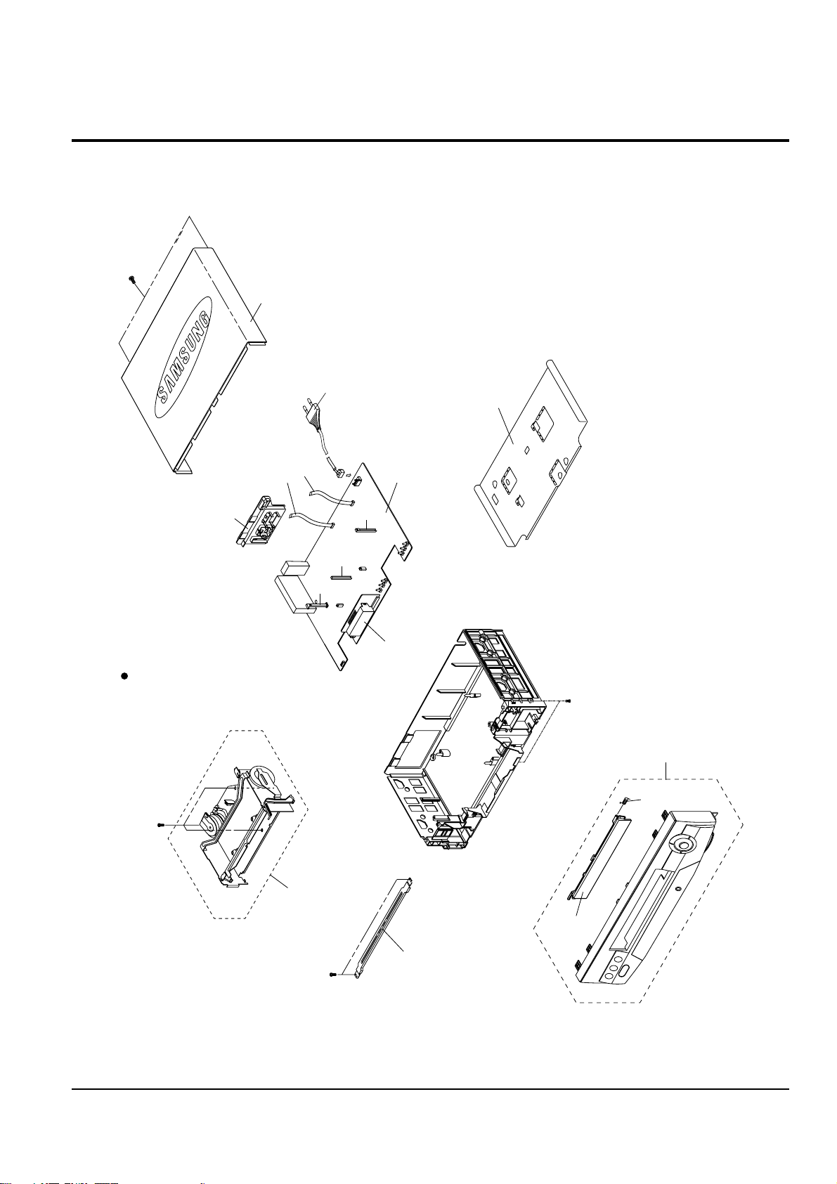
3-1 Cabinet Assembly
S.N.A. : Service Not Available
157
153
FULL DECK (S.N.A.)
TM401B
200
MAIN PCB (S.N.A.)
BRACKET-FRAME
(S.N.A.)
CN602S
CN3A1S
101
155
S601A
LD601A
S602A
LED PCB (S.N.A.)
102
157
1
1
21
22

Exploded View and Parts List
Samsung Electronics 3-3
Loc. No Parts No. Description ; Specification Remark
1 AC97-00033A ASSY-PANEL FRONT;SVR-527,HIPS 94HB,BLK
21 AC64-50995G DOOR-CASSETTE;-,ABS,-,T2.5,189*28,GRAY,22 AC61-62032A SPRING-MASK;X-9,-,SUS,-,4.4,-,SV-C130
101 AC64-30892A CABINET-TOP;X-9,SECC,PCM,0.5,360*208*41,
102 AC63-30519A COVER-BOTTOM;SV-C833,SPTE,-,T0.3,-,-,-,X
153 AC60-12126A SCREW-BH;-,BH,-,4*12,FE,FZY,-,-,155 AC60-12134A SCREW-TAP BH;-,BH,-,2-4X16,-,FE
157 AC60-10063A SCREW-TAPTITE;BH,+,-,M3,L12,ZPC3,SWRCH18
200 AC39-10019A POWER CORD;KKP-419C,H03VVH2-F,VDE/KEMA-K
CN3A1S 3809-001110 CABLE-FLAT;30V,80C,150mm,7P,1.25mm,UL289
CN602S 3809-001112 CABLE-FLAT;30V,80C,130mm,5P,1.25mm,UL289
LD601A AC61-21009A HOLDER-LED;-,POM(M90-44),-,BLK,-,X-9
S601A AC61-21008A HOLDER-SENSOR;-,POM(M90-44),-,BLK,-,X-9
S602A AC61-21008A HOLDER-SENSOR;-,POM(M90-44),-,BLK,-,X-9
TM401B AC61-11063B CONNECTOR BOARD-ASSY;SV-C17DV,HIPS94,HB,
Exploded View and Parts List
3-4 Samsung Electronics
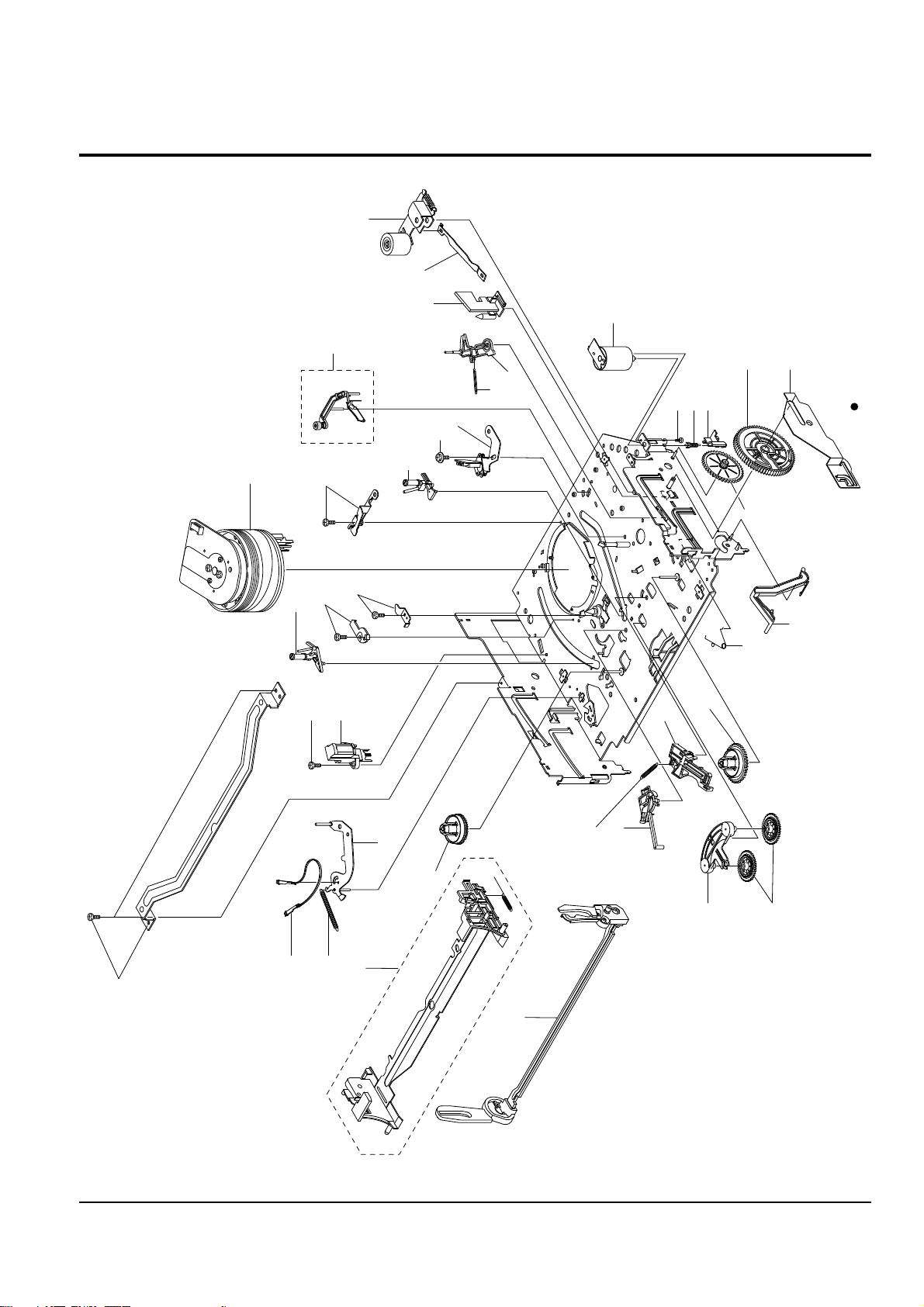
3-2 Mechanical Parts (Top Side)
G001
K250
K248
K110
K502
K350
K330
K182
K140
K490
K530
K240
G532
G420
G450
K546
G510
B410
B440
B444
B446
B448
B452
G527
G520
G480
G680
S.N.A.
S.N.A.
S.N.A.
S.N.A.
S.N.A.
G530
K340
B473
K188
G555
G546
S.N.A. : Service Not Available
S.N.A.

Exploded View and Parts List
Samsung Electronics 3-5
Loc. No Parts No. Description ; Specification Remark
B410 AC31-12016A MOTOR-LOADING ASSY;-,-,X-9
B440 AC60-10515A SCREW-MACHINE;-,PH,+,-,M3,L3,ZPC,-,YEL
B444 AC66-20571A GEAR-WORM;-,POM SW-01,0.5,2,-,4.5,X-9
B446 AC61-21005A HOLDER-WORM;-,POM M90-44,-,-,-,X-9
B448 AC66-20573A GEAR-WORM WHEEL;-,POM SW-01,0.6,11,-,6.6
B452 AC66-20575A GEAR-FL CAM;-,POM SW-01,M0.6,Z88,-,PCD58
B473 AC61-60559A SPRING-PINCH DRIVE;-,TS,SUS304,PI0.5,OD4
G001 AC96-10482L ASSY-CYLINDER;CX-9, PAL 2HD(SP)HI-FI
G420 AC66-80142A SLIDER-SUPPLY ASSY;-,X-9(TS),-,-,-,X-9
G450 AC66-80141A SLIDER-TAKE UP ASSY;-,X-9(TS),-,-,-,X-9
G480 AC33-10217H HEAD-ACE ASSY;-,-,-,-,X-9
G510 AC60-10518A SCREW-TAP TITE;-,PH,+,SW+ZW,M2.6,L5.6,ZP
G520 AC66-30539A LEVER-#9 GUIDE ASSY;-,X-9(TS),-,-,-,X-9
G527 AC61-60553A SPRING-#9 GUIDE;-,ES,SUS304-WPB,OD3.1,0.
G530 AC33-10217G HEAD-FE;VAA00000275,-,-,-,X-9
G532 AC60-10519A SCREW-TAP TITE;-,PH,+,-,M2.6,L8,ZPC
G546 AC66-30535A LEVER-FL DOOR;-,POM M90-44,-,-,BLK,X-9
G555 AC59-90403A UNIT-PINCH ASSY;X-9,G680 AC66-30557A LEVER-H/CLEANER ASSY;-,POM+URETHANE,-,- (OPTIONAL)
K110 AC66-10267A REEL-DISK S;-,POM M90-44,-,-,X-9
K140 AC66-10268A REEL-DISK T;-,POM M90-44,-,-,X-9
K182 AC66-30524A LEVER-IDLER;-,POM9044,-,-,-,K188 AC66-20577A GEAR-IDLER;-,PEBAX 7033,-,-,-,-,X-9
K240 AC66-30538A LEVER-TENSION ASSY;-,X-9(TS),-,-,-,X-9
K248 AC61-60554A SPRING-TENSION LEVER;-,ES,SUS304-WPB,OD3
K250 AC63-12029A BAND-BRAKE ASSY;-,X-9(TS),-,-,-,X-9
K330 AC66-30550A LEVER-S.BRAKE ASSY;-,POM+SUS,-,-,-,X-9
K340 AC66-30549A LEVER-T.BRAKE ASSY;-,POM+SUS,-,-,-,X-9
K350 AC61-60564A SPRING-BRAKE;-,TENSION,SWP-A,0.25,3,-,XK490 AC61-21010B HOLDER-CASS ASSY;-,SECC+POM+SUS,-,-,-,XK502 AC61-60561A SPRING-FL.LEVER-LR;-,ES,SUS304 WPB,PI2.7
K530 AC66-30546A LEVER-FL.ARM ASS’Y;-,SECC+POM+SUS,-,-,-,
K546 AC61-50658A GUIDE-CASS. DOOR;-,POM M90-44,-,-,NTR,-,
Exploded View and Parts List
3-6 Samsung Electronics
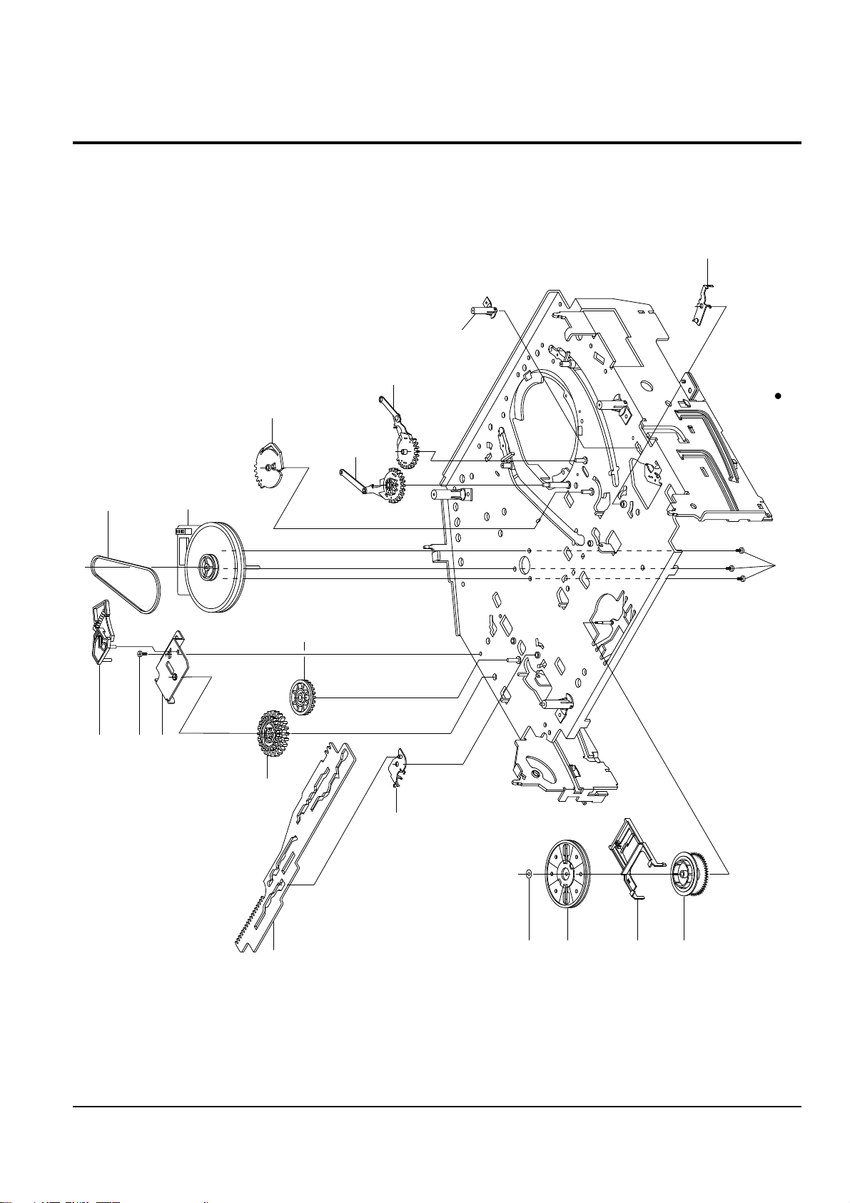
3-3 Mechanical Parts (Bottom Side)
G542
B560
B484
B458
B500
B488
B462
(OPTIONAL)
S.N.A.
S.N.A.
S.N.A.
S.N.A.
B456
K222
K200
K225
K221
B570
B238
S.N.A. : Service Not Available

Exploded View and Parts List
Samsung Electronics 3-7
Loc. No Parts No. Description ; Specification Remark
B238 AC61-50660A SLEEVE-TENSION;-,POM M90-44,-,-,ID3,-,-,
B456 AC66-20576A GEAR-JOINT 1;-,POM SW-01,M1.0,Z22,-,PCD2
B458 AC66-20574A GEAR-JOINT 2;-,POM SW-01,M1.0,Z14,-,PCD1
B462 AC60-10517A SCREW-TAP TITE;-,PH,+,-,M2.6,L5,ZPC,-,YE
B484 AC66-20580A GEAR-LOADING DRIVE;-,POM SW-01,M1.0,Z32,
B488 AC66-30543A LEVER-S LOAD ASSY;-,-,-,-,-,X-9
B500 AC66-30542A LEVER-T LOAD ASSY;-,-,-,-,-,X-9
B560 AC31-12017A MOTOR-CAPSTAN;DMVCMC07C,-,X-9
B570 AC60-10514A SCREW-CAPSTAN;-,PH,+,M2.6,L6,G542 AC66-60051A BELT-PULLEY;-,5CM-70,2 * 2,-,71.3,-,X-9
K200 AC61-21012A HOLDER-CLUTCH ASSY;-,-,-,-,-,X-9
K221 AC66-20581A GEAR-CENTER ASSY;-,POM,M=O.5,-,HIGHT T.,
K222 AC60-30306A WASHER-SLIT;-,-,ID2.1,OD5.0,T0.5,-,POLYS
K225 AC66-30547A LEVER-UP DOWN ASSY;-,POM+SUS,-,-,-,X-9

Exploded View and Parts List
3-8 Samsung Electronics
MEMO

Loc.No Part No Description ; Specification Remark Loc.No Part No Description ; Specification Remark
Samsung Electronics
4-1
- - ASSY-PCB-MAIN;SVR-527/XEV,2HD HIFI VCP S.N.A.
S.M.P.S. PARTS
BD1SD1 AC27-92001M INDUCTOR;70UH-M RT BFS3565R2F,-,-,-,BD1SR1 3301-000297 CORE-FERRITE BEAD;AA,3.6x1.2x5.7mm,1400,
BD1SS2 AC27-92001M INDUCTOR;70UH-M RT BFS3565R2F,-,-,-,BD1SS3 AC27-92001M INDUCTOR;70UH-M RT BFS3565R2F,-,-,-,C1SD03 2201-000934 C-CERAMIC,DISC;3.3nF,20%,400V,Y5U,TP,18x
C1SD04 2201-000934 C-CERAMIC,DISC;3.3nF,20%,400V,Y5U,TP,18x
C1SD11 2401-003302 C-AL;47uF,20%,400V,GP,TP,18X31.5,7.
C1SD12 2201-000934 C-CERAMIC,DISC;3.3nF,20%,400V,Y5U,TP,18x
C1SR12 2401-000905 C-AL;22UF,20%,16V,BP,-,6X11,2.5MM
C1SR13 2301-000361 C-FILM,PEF;1.2NF,10%,50V,TP,-,5MM
C1SR14 2301-000445 C-FILM,PEF;4.7nF,5%,50V,TP,5.5x7x3mm,5mm
C1SS01 2305-001021 C-FILM,MPEF;100nF,20%,275V,TP,17.5x7x13.
C1SS02 2305-001021 C-FILM,MPEF;100nF,20%,275V,TP,17.5x7x13.
C1SS12 2201-000129 C-CERAMIC,DISC;100pF,10%,1KV,Y5P,TP,6x5,
C1SS31 2401-000392 C-AL;10uF,20%,100V,WT,TP,6.3x11,2.5
C1SS32 2401-001126 C-AL;330uF,20%,25V,WT,TP,10x12.5,5
C1SS33 2401-002162 C-AL;1000uF,20%,25V,WT,TP,10x20,5mm
C1SS34 2401-001126 C-AL;330uF,20%,25V,WT,TP,10x12.5,5
C1SS35 2401-001992 C-AL;2200UF,20%,10V,WT,TP,10X20MM,5
C1SS36 2401-001479 C-AL;470uF,20%,10V,GP,-,-,TP
C1SS39 2301-000129 C-FILM,PEF;100nF,5%,50V,TP,10X9X4.3X5,5m
C1SS41 2301-000423 C-FILM,PEF;3.3NF,5%,100V,TP,7X10X4.5MM,5
CN1SS1 3711-000178 CONNECTOR-HEADER;1WALL,2P,1R,3.96mm,STRA
D1SD31 0402-001195 DIODE-RECTIFIER;F1T4,400V,1.0A,TS-1,TP
D1SR11 0401-000101 DIODE-SWITCHING;1N4148,100V,200mA,DO-35,
D1SS01 0402-001196 DIODE-RECTIFIER;1T5,600V,1A,TS-1,TP
D1SS02 0402-001196 DIODE-RECTIFIER;1T5,600V,1A,TS-1,TP
D1SS03 0402-001196 DIODE-RECTIFIER;1T5,600V,1A,TS-1,TP
D1SS04 0402-001196 DIODE-RECTIFIER;1T5,600V,1A,TS-1,TP
D1SS11 0402-000276 DIODE-RECTIFIER;UF4007,1KV,1A,DO-41,TP
D1SS12 0402-001195 DIODE-RECTIFIER;F1T4,400V,1.0A,TS-1,TP
D1SS31 0402-001195 DIODE-RECTIFIER;F1T4,400V,1.0A,TS-1,TP
D1SS32 0402-000431 DIODE-RECTIFIER;FML-M02S,200V,2.5A,TO-22
D1SS33 0402-001194 DIODE-RECTIFIER;UG2D,200V,2A,DO-204AC,TP
F1SS01 3601-001122 FUSE-FERRULE;250V,1.6A,FA,GLASS,5.2x20mm
IC1SS1 0604-001028 PHOTO-COUPLER;TR,50-600%,250mW,DIP-4,ST
IC1SS2 AC14-12006D IC;KA431Z,TO-92,TAPING
L1SS02 AC29-30050C FILTER-LINE NOISE;-,25MH,0.35A,AC250V,BS
L1SS31 AC27-12001N COIL-CHOKE;10UH-15%,RA,K-30,Q80,150KHZ,L1SS32 AC27-12001N COIL-CHOKE;10UH-15%,RA,K-30,Q80,150KHZ,PT1SD1 AC26-20120L TRANS-SWITCHING;DP,230V,UL/CSA/DEMKO,EE2
Q1SR01 0502-001050 TR-POWER;2SC4517A,NPN,30W,TO-220,ST,10Q1SR12 0501-000442 TR-SMALL SIGNAL;KTC3203-Y,NPN,400MW,T0-9
R1SD11 2001-000305 R-CARBON;110KOHM,5%,1/8W,AA,TP,1.8X3.2MM
R1SD12 2001-000003 R-CARBON;330OHM,5%,1/8W,AA,TP,1.8X3.2MM
R1SD13 2001-000305 R-CARBON;110KOHM,5%,1/8W,AA,TP,1.8X3.2MM
R1SD14 2001-000305 R-CARBON;110KOHM,5%,1/8W,AA,TP,1.8X3.2MM
R1SD15 2001-000305 R-CARBON;110KOHM,5%,1/8W,AA,TP,1.8X3.2MM
R1SD16 2006-000273 R-CEMENT;27Kohm,5%,2W,CA,BK,6.4x27x6.4m
R1SD31 2001-000515 R-CARBON;220OHM,5%,1/8W,AA,TP,1.8X3.2MM
R1SD32 2001-000221 R-CARBON;1.2KOHM,5%,1/8W,AA,TP,1.8X3.2MM
R1SR11 2003-000119 R-METAL OXIDE;0.68ohm,5%,2W,AE,TP,6x16mm
R1SR12 2003-000264 R-METAL OXIDE;300ohm,5%,1W,AD,TP,4.3x12m
R1SR14 2001-000003 R-CARBON;330OHM,5%,1/8W,AA,TP,1.8X3.2MM
R1SS10 2006-000262 R-CEMENT;2.7ohm,10%,2W,CB,ST,7.5x11x20.
R1SS13 2003-000148 R-METAL OXIDE;100OHM,5%,2W,AE,TP,6X16MM
R1SS32 2001-000429 R-CARBON;1KOHM,5%,1/8W,AA,TP,1.8X3.2MM
R1SS33 2004-000869 R-METAL;3Kohm,1%,1/8W,AA,TP,1.8x3.2mm
R1SS34 2004-000459 R-METAL;2.2Kohm,1%,1/8W,AA,TP,1.8x3.2m
VA1SS1 1405-001026 VARISTOR;470V,600A,9x7mm,TP
ZD1SR1 0403-000571 DIODE-ZENER;UZP43B,43V,40-46V,1W,DO-41,T
POWER DRIVE PARTS
C1P101 2401-000598 C-AL;1uF,20%,50V,GP,TP,4x7,5
C1P102 2401-003107 C-AL;47uF,20%,16V,GP,TP,5x7,5
C1P103 2401-000598 C-AL;1uF,20%,50V,GP,TP,4x7,5
C1P104 2401-002299 C-AL;4.7uF,20%,50V,GP,TP,5x7,5
C1P105 2401-003107 C-AL;47uF,20%,16V,GP,TP,5x7,5
C1P106 2401-000598 C-AL;1uF,20%,50V,GP,TP,4x7,5
C1P107 2401-003107 C-AL;47uF,20%,16V,GP,TP,5x7,5
C1P108 2401-003107 C-AL;47uF,20%,16V,GP,TP,5x7,5
C1P109 2401-003107 C-AL;47uF,20%,16V,GP,TP,5x7,5
C1P110 2401-000598 C-AL;1uF,20%,50V,GP,TP,4x7,5
D1P101 0401-000101 DIODE-SWITCHING;1N4148,100V,200mA,DO-35,
D1P102 0401-000101 DIODE-SWITCHING;1N4148,100V,200mA,DO-35,
D1P103 0402-000127 DIODE-RECTIFIER;1N4002,100V,1A,DO-41,TP
D1P104 0402-000127 DIODE-RECTIFIER;1N4002,100V,1A,DO-41,TP
D1P105 0402-000127 DIODE-RECTIFIER;1N4002,100V,1A,DO-41,TP
D1P106 0401-000101 DIODE-SWITCHING;1N4148,100V,200mA,DO-35,
D1P108 0402-000127 DIODE-RECTIFIER;1N4002,100V,1A,DO-41,TP
D1P109 0402-000127 DIODE-RECTIFIER;1N4002,100V,1A,DO-41,TP
Q1P101 0501-000616 TR-SMALL SIGNAL;KSC2328A-Y,NPN,1W,TO-92L
Q1P102 0501-000616 TR-SMALL SIGNAL;KSC2328A-Y,NPN,1W,TO-92L
Q1P103 0501-000616 TR-SMALL SIGNAL;KSC2328A-Y,NPN,1W,TO-92L
Q1P104 0501-000610 TR-SMALL SIGNAL;KSA928A-Y,PNP,1W,TO-92L,
Q1P105 0504-000116 TR-DIGITAL;KSR1001,NPN,300MW,4.7K/4.7K,T
Q1P106 0504-000142 TR-DIGITAL;KSR2001,PNP,300MW,4.7K/4.7K,T
Q1P107 0501-000442 TR-SMALL SIGNAL;KTC3203-Y,NPN,400MW,T0-9
Q1P108 0501-000398 TR-SMALL SIGNAL;KSC945,NPN,250mW,TO-92,T
Q1P109 0501-000442 TR-SMALL SIGNAL;KTC3203-Y,NPN,400MW,T0-9
R1P101 2001-000855 R-CARBON;560OHM,5%,1/4W,AA,TP,2.4X6.4MM
R1P102 2001-000855 R-CARBON;560OHM,5%,1/4W,AA,TP,2.4X6.4MM
R1P103 2001-000034 R-CARBON;220OHM,5%,1/4W,AA,TP,2.4X6.4MM
R1P104 2001-000554 R-CARBON;270OHM,5%,1/8W,AA,TP,1.8X3.2MM
R1P105 2001-000273 R-CARBON;100KOHM,5%,1/8W,AA,TP,1.8X3.2MM
R1P106 2001-000611 R-CARBON;3.9KOHM,5%,1/4W,AA,TP,2.4X6.4MM
R1P107 2001-000449 R-CARBON;2.2KOHM,5%,1/8W,AA,TP,1.8X3.2MM
R1P108 2001-000449 R-CARBON;2.2KOHM,5%,1/8W,AA,TP,1.8X3.2MM
R1P115 2001-000362 R-CARBON;150OHM,5%,1/8W,AA,TP,1.8X3.2MM
R1P116 2001-000734 R-CARBON;4.7KOHM,5%,1/8W,AA,TP,1.8X3.2MM
R1P117 2001-000290 R-CARBON;10KOHM,5%,1/8W,AA,TP,1.8X3.2MM
ZD1P01 0403-001211 DIODE-ZENER;MTZJ12B,11.44-12.03V,500MW,D
ZD1P02 0403-000557 DIODE-ZENER;MTZ5.1C,5.1V,5.09-5.37V,500m
ZD1P03 0403-000720 DIODE-ZENER;MTZJ9.1B,9.1V,8.57-9.01V,500
SYSTEM CONTROL/SERVO PARTS
C601 2202-002037 C-CERAMIC,MLC-AXIAL;100nF,80-20%,50V,Y5V
C602 2202-002037 C-CERAMIC,MLC-AXIAL;100nF,80-20%,50V,Y5V
C603 2401-003107 C-AL;47uF,20%,16V,GP,TP,5x7,5
C604 2202-000797 C-CERAMIC,MLC-AXIAL;10NF,30%,16V,Y5S,TP,
C605 2202-000797 C-CERAMIC,MLC-AXIAL;10NF,30%,16V,Y5S,TP,
C606 2202-000797 C-CERAMIC,MLC-AXIAL;10NF,30%,16V,Y5S,TP,
C608 2401-000414 C-AL;10uF,20%,16V,GP,TP,4x7,5
C609 2202-000797 C-CERAMIC,MLC-AXIAL;10NF,30%,16V,Y5S,TP,
C610 2401-003107 C-AL;47uF,20%,16V,GP,TP,5x7,5
C611 2202-000797 C-CERAMIC,MLC-AXIAL;10NF,30%,16V,Y5S,TP,
C612 2202-000797 C-CERAMIC,MLC-AXIAL;10NF,30%,16V,Y5S,TP,
C613 2301-000471 C-FILM,PEF;68nF,5%,50V,TP,9x12x4.5mm,5mm
C615 2202-000797 C-CERAMIC,MLC-AXIAL;10NF,30%,16V,Y5S,TP,
C616 2401-001545 C-AL;47uF,20%,25V,GP,TP,6.3x7mm,2.5
C617 2401-001545 C-AL;47uF,20%,25V,GP,TP,6.3x7mm,2.5
4. Electrical Parts List

Loc.No Part No Description ; Specification RemarkLoc.No Part No Description ; Specification Remark
4-2
Samsung Electronics
Electrical Parts List
C618 2202-000797 C-CERAMIC,MLC-AXIAL;10NF,30%,16V,Y5S,TP,
C619 2401-003107 C-AL;47uF,20%,16V,GP,TP,5x7,5
C620 2202-002037 C-CERAMIC,MLC-AXIAL;100nF,80-20%,50V,Y5V
C621 2401-000414 C-AL;10uF,20%,16V,GP,TP,4x7,5
C622 2202-000145 C-CERAMIC,MLC-AXIAL;.12NF,10%,50V,Y5P,TP
C623 2401-002299 C-AL;4.7uF,20%,50V,GP,TP,5x7,5
C624 2202-002037 C-CERAMIC,MLC-AXIAL;100nF,80-20%,50V,Y5V
C625 2202-002037 C-CERAMIC,MLC-AXIAL;100nF,80-20%,50V,Y5V
C626 2202-000263 C-CERAMIC,MLC-AXIAL;470pF,10%,50V,Y5P,TP
C629 2202-000830 C-CERAMIC,MLC-AXIAL;82pF,10%,50V,Y5P,TP,
C630 2401-002069 C-AL;33uF,20%,16V,GP,TP,6.3x5,5
C631 2202-000830 C-CERAMIC,MLC-AXIAL;82pF,10%,50V,Y5P,TP,
C632 2401-000918 C-AL;22uF,20%,16V,GP,-,6.3x7,5
C633 2202-000807 C-CERAMIC,MLC-AXIAL;22nF,+80-20%,25V,Y5V
C634 2401-001507 C-AL;47uF,20%,16V,GP,TP,6.3x5,5
C635 2401-001775 C-AL;470nF,20%,50V,GP,TP,4x7,5
C636 2202-000797 C-CERAMIC,MLC-AXIAL;10NF,30%,16V,Y5S,TP,
C637 2202-000121 C-CERAMIC,MLC-AXIAL;100pF,10%,50V,Y5P,TP
C638 2202-000216 C-CERAMIC,MLC-AXIAL;.027NF,5%,50V,SL,TP,
C639 2202-000216 C-CERAMIC,MLC-AXIAL;.027NF,5%,50V,SL,TP,
C640 2202-000162 C-CERAMIC,MLC-AXIAL;.015NF,5%,50V,SL,TP,
C641 2202-000162 C-CERAMIC,MLC-AXIAL;.015NF,5%,50V,SL,TP,
C644 2301-000392 C-FILM,PEF;15nF,5%,50V,TP,6.5x8.5x3.2mm,
C645 2202-000205 C-CERAMIC,MLC-AXIAL;22pF,5%,50V,SL,TP,1.
C646 2202-000205 C-CERAMIC,MLC-AXIAL;22pF,5%,50V,SL,TP,1.
C647 2202-000162 C-CERAMIC,MLC-AXIAL;.015NF,5%,50V,SL,TP,
C650 2401-001507 C-AL;47uF,20%,16V,GP,TP,6.3x5,5
C689 2301-000471 C-FILM,PEF;68nF,5%,50V,TP,9x12x4.5mm,5mm
C690 2202-000797 C-CERAMIC,MLC-AXIAL;10NF,30%,16V,Y5S,TP,
CN601 AC39-20817S LEAD CONNECTOR-ASSY;DP,SMH200-02,YBH200CN602 3708-001163 CONNECTOR-FPC/FC/PIC;5P,1.25mm,STRAIGHT,
CN604 3711-003749 CONNECTOR-HEADER;BOX,8P,2R,2mm,STRAIGHT,
D601 0401-000101 DIODE-SWITCHING;1N4148,100V,200mA,DO-35,
D602 0401-000101 DIODE-SWITCHING;1N4148,100V,200mA,DO-35,
D603 0401-000101 DIODE-SWITCHING;1N4148,100V,200mA,DO-35,
D605 0402-000127 DIODE-RECTIFIER;1N4002,100V,1A,DO-41,TP
D606 0402-000127 DIODE-RECTIFIER;1N4002,100V,1A,DO-41,TP
D608 0401-000101 DIODE-SWITCHING;1N4148,100V,200mA,DO-35,
D609 0401-000101 DIODE-SWITCHING;1N4148,100V,200mA,DO-35,
D610 0401-000101 DIODE-SWITCHING;1N4148,100V,200mA,DO-35,
D611 0401-000101 DIODE-SWITCHING;1N4148,100V,200mA,DO-35,
D612 0401-000101 DIODE-SWITCHING;1N4148,100V,200mA,DO-35,
D613 0401-000101 DIODE-SWITCHING;1N4148,100V,200mA,DO-35,
D614 0401-000101 DIODE-SWITCHING;1N4148,100V,200mA,DO-35,
D615 0402-000127 DIODE-RECTIFIER;1N4002,100V,1A,DO-41,TP
D616 0401-000101 DIODE-SWITCHING;1N4148,100V,200mA,DO-35,
D620 0402-000127 DIODE-RECTIFIER;1N4002,100V,1A,DO-41,TP
D621 0401-000101 DIODE-SWITCHING;1N4148,100V,200mA,DO-35,
D630 0401-000101 DIODE-SWITCHING;1N4148,100V,200mA,DO-35,
D640 0401-000101 DIODE-SWITCHING;1N4148,100V,200mA,DO-35,
IC601 AC09-00011A IC-MCU;HD643977RF,100P,-,SVK-C17DV,16BIT
IC602 1003-001162 IC-MOTOR DRIVER;KA3082,SIP,10PIN,25MIL,D
IC603 1103-000190 IC-EEPROM;24C02,256x8BIT,DIP,8P,300MIL,1
IC604 AC14-12006C IC;KA7533,DIP,L601 AC27-92001B COIL-PEAKING AXIAL;BAL04ST101K,-,-,-,L602 AC27-92001B COIL-PEAKING AXIAL;BAL04ST101K,-,-,-,L603 AC27-92001B COIL-PEAKING AXIAL;BAL04ST101K,-,-,-,L604 2701-000117 INDUCTOR-AXIAL;10uH,5%,2.4x3.4mm
L605 AC27-92001B COIL-PEAKING AXIAL;BAL04ST101K,-,-,-,L606 AC27-92001B COIL-PEAKING AXIAL;BAL04ST101K,-,-,-,L607 2701-000131 INDUCTOR-AXIAL;15uH,5%,2.4x3.4mm
L608 AC27-92001B COIL-PEAKING AXIAL;BAL04ST101K,-,-,-,LD601 0601-000517 LED-IR;RECTANGULA,4x6.0mm,75mW,6V,950
PT601 0604-001122 PHOTO-INTERRUPTER;TR,0.065%,150mW,DIP-4,
PT602 0604-001122 PHOTO-INTERRUPTER;TR,0.065%,150mW,DIP-4,
Q601 0501-000303 TR-SMALL SIGNAL;KSA733,PNP,250mW,TO-92,T
Q602 0501-000398 TR-SMALL SIGNAL;KSC945,NPN,250mW,TO-92,T
Q603 0501-000398 TR-SMALL SIGNAL;KSC945,NPN,250mW,TO-92,T
Q604 0501-000398 TR-SMALL SIGNAL;KSC945,NPN,250mW,TO-92,T
R601 2003-000259 R-METAL OXIDE;3.9OHM,5%,2W,AE,TP,6X16MM
R602 2001-000281 R-CARBON;100OHM,5%,1/8W,AA,TP,1.8X3.2MM
R603 2001-000281 R-CARBON;100OHM,5%,1/8W,AA,TP,1.8X3.2MM
R604 2001-000362 R-CARBON;150OHM,5%,1/8W,AA,TP,1.8X3.2MM
R605 2001-000522 R-CARBON;22KOHM,5%,1/8W,AA,TP,1.8X3.2MM
R606 2001-000633 R-CARBON;30KOHM,5%,1/8W,AA,TP,1.8X3.2MM
R607 2001-000734 R-CARBON;4.7KOHM,5%,1/8W,AA,TP,1.8X3.2MM
R608 2001-000734 R-CARBON;4.7KOHM,5%,1/8W,AA,TP,1.8X3.2MM
R609 2001-000734 R-CARBON;4.7KOHM,5%,1/8W,AA,TP,1.8X3.2MM
R610 2001-000429 R-CARBON;1KOHM,5%,1/8W,AA,TP,1.8X3.2MM
R611 2001-000010 R-CARBON;68KOHM,5%,1/8W,AA,TP,1.8X3.2MM
R612 2001-000281 R-CARBON;100OHM,5%,1/8W,AA,TP,1.8X3.2MM
R613 2001-000780 R-CARBON;470OHM,5%,1/8W,AA,TP,1.8X3.2MM
R614 2001-000864 R-CARBON;56KOHM,5%,1/8W,AA,TP,1.8X3.2MM
R615 2001-000435 R-CARBON;1MOHM,5%,1/8W,AA,TP,1.8X3.2MM
R616 2001-000429 R-CARBON;1KOHM,5%,1/8W,AA,TP,1.8X3.2MM
R617 2001-000429 R-CARBON;1KOHM,5%,1/8W,AA,TP,1.8X3.2MM
R618 2001-000281 R-CARBON;100OHM,5%,1/8W,AA,TP,1.8X3.2MM
R619 2001-000773 R-CARBON;470KOHM,5%,1/8W,AA,TP,1.8X3.2MM
R620 2001-000290 R-CARBON;10KOHM,5%,1/8W,AA,TP,1.8X3.2MM
R621 2001-000786 R-CARBON;47KOHM,5%,1/8W,AA,TP,1.8X3.2MM
R622 2001-000786 R-CARBON;47KOHM,5%,1/8W,AA,TP,1.8X3.2MM
R623 2001-000802 R-CARBON;5.6Kohm,5%,1/8W,AA,TP,1.8x3.2m
R624 2001-000429 R-CARBON;1KOHM,5%,1/8W,AA,TP,1.8X3.2MM
R625 2001-000864 R-CARBON;56KOHM,5%,1/8W,AA,TP,1.8X3.2MM
R626 2001-000429 R-CARBON;1KOHM,5%,1/8W,AA,TP,1.8X3.2MM
R627 2001-000429 R-CARBON;1KOHM,5%,1/8W,AA,TP,1.8X3.2MM
R628 2001-000429 R-CARBON;1KOHM,5%,1/8W,AA,TP,1.8X3.2MM
R629 2001-000429 R-CARBON;1KOHM,5%,1/8W,AA,TP,1.8X3.2MM
R630 2001-000429 R-CARBON;1KOHM,5%,1/8W,AA,TP,1.8X3.2MM
R631 2001-000429 R-CARBON;1KOHM,5%,1/8W,AA,TP,1.8X3.2MM
R632 2001-000429 R-CARBON;1KOHM,5%,1/8W,AA,TP,1.8X3.2MM
R633 2001-000864 R-CARBON;56KOHM,5%,1/8W,AA,TP,1.8X3.2MM
R635 2001-000290 R-CARBON;10KOHM,5%,1/8W,AA,TP,1.8X3.2MM
R636 2001-000290 R-CARBON;10KOHM,5%,1/8W,AA,TP,1.8X3.2MM
R637 2001-000761 R-CARBON;430OHM,5%,1/8W,AA,TP,1.8X3.2MM
R638 2001-000761 R-CARBON;430OHM,5%,1/8W,AA,TP,1.8X3.2MM
R639 2001-000290 R-CARBON;10KOHM,5%,1/8W,AA,TP,1.8X3.2MM
R640 2001-000429 R-CARBON;1KOHM,5%,1/8W,AA,TP,1.8X3.2MM
R641 2001-000435 R-CARBON;1MOHM,5%,1/8W,AA,TP,1.8X3.2MM
R642 2001-000802 R-CARBON;5.6Kohm,5%,1/8W,AA,TP,1.8x3.2m
R643 2001-000290 R-CARBON;10KOHM,5%,1/8W,AA,TP,1.8X3.2MM
R644 2001-000258 R-CARBON;1.8KOHM,5%,1/8W,AA,TP,1.8X3.2MM
R645 2001-000429 R-CARBON;1KOHM,5%,1/8W,AA,TP,1.8X3.2MM
R648 2001-000429 R-CARBON;1KOHM,5%,1/8W,AA,TP,1.8X3.2MM
R649 2001-000429 R-CARBON;1KOHM,5%,1/8W,AA,TP,1.8X3.2MM
R650 2001-000429 R-CARBON;1KOHM,5%,1/8W,AA,TP,1.8X3.2MM
R651 2001-000429 R-CARBON;1KOHM,5%,1/8W,AA,TP,1.8X3.2MM
R652 2001-000429 R-CARBON;1KOHM,5%,1/8W,AA,TP,1.8X3.2MM
R655 2001-000435 R-CARBON;1MOHM,5%,1/8W,AA,TP,1.8X3.2MM
R657 2001-000290 R-CARBON;10KOHM,5%,1/8W,AA,TP,1.8X3.2MM
R658 2001-000241 R-CARBON;1.5KOHM,5%,1/8W,AA,TP,1.8X3.2MM
R659 2001-000786 R-CARBON;47KOHM,5%,1/8W,AA,TP,1.8X3.2MM
R660 2001-000802 R-CARBON;5.6Kohm,5%,1/8W,AA,TP,1.8x3.2m
R661 2001-000435 R-CARBON;1MOHM,5%,1/8W,AA,TP,1.8X3.2MM
R662 2001-000802 R-CARBON;5.6Kohm,5%,1/8W,AA,TP,1.8x3.2m
R670 2001-000290 R-CARBON;10KOHM,5%,1/8W,AA,TP,1.8X3.2MM
R678 2001-000522 R-CARBON;22KOHM,5%,1/8W,AA,TP,1.8X3.2MM
R679 2001-000515 R-CARBON;220OHM,5%,1/8W,AA,TP,1.8X3.2MM
R680 2001-000429 R-CARBON;1KOHM,5%,1/8W,AA,TP,1.8X3.2MM
R682 2001-000522 R-CARBON;22KOHM,5%,1/8W,AA,TP,1.8X3.2MM
R686 2001-000290 R-CARBON;10KOHM,5%,1/8W,AA,TP,1.8X3.2MM
R687 2001-000290 R-CARBON;10KOHM,5%,1/8W,AA,TP,1.8X3.2MM
 Loading...