

Samsung SNS-110 User Manual

WEB
WEB
TRANSMITTER
SNS-110 Owner's Manual
(Version 1.1)
1
2
4

2
[Power Adapter]
You must use only a compatible power adapter enclosed in SNS-110 package.
[Fuse]
You must use only an identical fuse (250V, T3.15A) used in SNS-110.
[Battery]
You must use only batteries (DC3V) applicable to SNS-110 usage to avoid
explosion risk.
This manual is the basic guide for all Web Transmitter SNS-110 users.
It mainly illustrates product background, installation method, and connection through web browsers
as well as GUI (Graphic User Interface) after connection.
Please, familiarize yourself of the contents in this manual before using SNS-110 product.
Make sure you refer to an expert when opening the outer case for the purpose of repair.
Also, if you have any inquiries or you suspect any damage in the product, please consult to your
local dealer.
Warning
Before You Begin

3
Regulation Appro val
Note: This equipment has been tested and found to comply with the limits for a
Class B digital device, pursuant to part 15 of the FCC Rules. These limits are
designed to provide reasonable protection against harmful interface in a
residential installation.
This equipment generates, uses and can radiate radio frequency energy and, if
not installed and used in accordance with the instructions, may cause harmful
interference to radio communications. However, there is no guarantee that
interference will not occur in a particular installation. If this equipment does
cause harmful interference to radio or television reception, which can be
determined by turning the equipment off and on, the user is encouraged to try to
correct the interference by one or more of the following measures:
- Reorient of relocate the receiving antenna.
- Increase the separation between the equipment and receiver.
- Connect the equipment into an outlet on a circuit different from that to which the
receiver is connected.
- Consult the dealer or an experienced radio TV technician for help.

4
Chapter 1. SNS-110 Overview - - - - - - - - - - - - - - - - - - - - - - - - - - - - - - - - - - - - - - - - - 6
Overview
- - - - - - - - - - - - - - - - - - - - - - - - - - - - - - - - - - - - - - - - - - - - - - - - - - - - - - - - 6
Functions and Feature
- - - - - - - - - - - - - - - - - - - - - - - - - - - - - - - - - - - - - - - - - - - - - - - 6
Names and Function
- - - - - - - - - - - - - - - - - - - - - - - - - - - - - - - - - - - - - - - - - - - - - - - - - 8
Chapter 2. Installing SNS-110 - - - - - - - - - - - - - - - - - - - - - - - - - - - - - - - - - - - - - - - - - 10
Setting Configuration
- - - - - - - - - - - - - - - - - - - - - - - - - - - - - - - - - - - - - - - - - - - - - - - - - 10
Cautions in Installation
--------------------------------------------11
Unpacking
--------------------------------------------------- 14
Chapter 3. Connecting to Instruments --------------------------------15
Connecting to Camera and Video Image Players
----------------------------15
Connecting to External Instruments
-----------------------------------16
Connecting to Network
-------------------------------------------17
Connecting to Alarm Sensors and External Devices
--------------------------18
Connecting to PAN/TILT/ZOOM/FOCUS Camera Controller
--------------------- 19
Connecting to RS-232C
--------------------------------------------20
Creating RS-232C Cable
------------------------------------------- 21
Terminal Emulation Communication Set-up
-------------------------------- 21
Creating Ethernet Cable
------------------------------------------ 22
Chapter 4. Setting an IP Address -----------------------------------23
Before You Begin
-----------------------------------------------23
Setting in Ethernet
----------------------------------------------24
Setting in Unix
------------------------------------------------26
Setting with IP Installer
------------------------------------ 28
Setting Other Network Information
------------------------------------ 32
Changing IP Address
--------------------------------------------32
In Cable Network through Cable Modem
---------------------------------33
Chapter 5. SNS-110 Log-in ----------------------------------------34
Ideal Specification
----------------------------------------------35
Log in through Netscape
------------------------------------------34
Log in through Explorer
-------------------------------------------35
Chapter 6. Application Mode (Video Image Monitoring Mode) ---------------39
Initial Screen
--------------------------------------------------39
Single Screen
-------------------------------------------------39
Quadruplex Screen
----------------------------------------------40
Automatic Sequential Screen
---------------------------------------40
Single Screen with PAN/TILT/ZOOM Controllers
----------------------------41
Table of Contents

Chapter 7. Administration Mode ------------------------------------ 42
Initial Screen
--------------------------------------------------42
Camera Set-up
------------------------------------------------43
PAN/TILT/ZOOM Set-up
------------------------------------------45
Quad/Sequential Set-up
-------------------------------------------46
Web Transmitter Set-up
-------------------------------------------47
Alarm/Relay Set-up
----------------------------------------------50
Network Set-up
------------------------------------------------52
File Transter Set-up
---------------------------------------------55
Custom User Interface Set-up
---------------------------------------57
ABOUT/SUPPORT/HELP
-----------------------------------------58
Appendix A ---------------------------------------------------60
SNS-110 Specifications
-------------------------------------------61
Appendix B ---------------------------------------------------64
Factory Default
------------------------------------------------65
Appendix C ---------------------------------------------------67
How to use Console
---------------------------------------------68
Appendix D ---------------------------------------------------77
Dynamic IP Information Transfer
------------------------------------- 78
Appendix E ---------------------------------------------------84
FAQ
------------------------------------------------------ 85
5?6

Chapter 1 SNS-110 Overview
Overview
SNS-110, connected to surveillance cameras or other external devices, compresses video image as
motion JPEG through zip algorithm and transmits it to a remote party through network (Ethernet, cable
modem).
SNS-110 may be connected to maximum of 4 video images and concurrently transmits the image in a
form of single screen, quadruplex screen, or automatic sequential screen.
Also, this system provides remote users in the Internet with alarm processing function and remote control
on PAN/TILT/ZOOM/FOCUS, succeeding in an extensive range of applications.
Functions and Features
● This system transmits real time images at any time with the network (Ethernet, cable modem) present.
● Users in the Internet are not required of additional S/W installation to receive the concurrent video
images, but may Log-in simply by accessing SNS-110 IP address with the existing web browser (such
as Netscape or Explorer).
● Users may select a type of screen, among Single Screen, Quadruplex Screen, and Automatic
Sequential Screen, and also may choose, at his or her preference, transmitting speed and resolution.
"Automatic Sequential" Screen provides the sequential and automatic changes in
size of the input images, depending on how the user has set up.
● This system transmits the image to the registered e-mail address at a particular point of time, by
setting up the alarm.
● Users may conveniently remote-control PAN/TILT/ZOOM/FOCUS under RS485 connection.
● Although the transmitted images are not locked in any way, users may set up ID and access
password.
● This system is usable regardless of the region because the image broadcasting system (NTSC/PAL) is
detected and operated with autornatic recognition.
● Auto terminal resistance function automatically withdraws the terminal resistance of 75Ω with the video
loop (loop through) connection.

● You can send video image files through FTP server at certain time or in regular intervals. Users can
access the FTP server and search the saved video files.
● You can change the LOGO image on SNS-110 screen, or background color or font colors.
Search SNS-110 to download the latest software at http://www.samsungelectronics.com/
7

8
①
Video In
②
Video Out
(Loop Through Out)
③
Control S/W
④
F H (S/W)
⑤
Tx R (S/W)
⑥
Rx R (S/W)
⑦
Network LED
⑧
Power LED
Preset Button
Reset Button
2
1
879
10
43
3
4
5 6
1.CONTROL 2.F/H 3.Tx R 4.Rx R
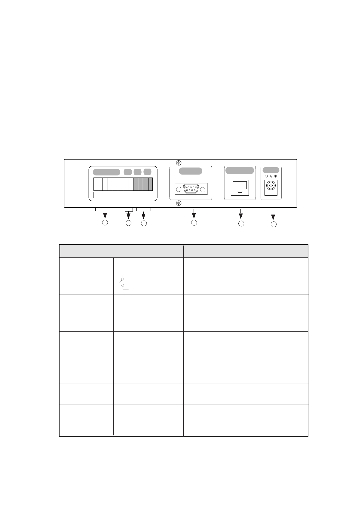
Names and Function
Familiarize yourself with the names and function of each part on the front and back panels, before
installing SNS-110.
Front View of SNS-110
Receives input from maximum of 4 video image signals.
Transmit the image output to cameras or other external video-imaging devices
❈
When connected, the terminal resistance of 75Ωis automatically seized.
Off : when using as console purpose with RS-232C port connected to a PC
On : when RS-232C is to be connected to an External Modem.
❈The current version does not support connecting an External Modem.
Off : use the RS-485 on the reverse side as Half Duplex
On : use the RS-485 on the reverse side as Full Duplex TX mode
Off : Tx Termination resistance 120 Ωoff
On : Tx Termination resistance 120 Ωon
Off : Rx Termination resistance 120 Ωoff
On : Rx Termination resistance 120 Ωon
Blinks when sending or receiving data with the proper connection.
Indicates the power on/off.
Returns to the initial set-up environment of factory default
Restarts SNS-110 without turning off the power.
Name Function
9
Rear of SNS-110
Connects to maximum of 4 alarm sensors.
Connected to the external device for remote control
Connects to RS-485 cable and remotely regulate
PAN/TILT/ZOOM/ FOCUS
controllers.
Full Duplex : use RX and TX.
Half Duplex : use TX .
Connects to console and an external modem through
the RS-232C cable connection.
❈ You are recommended to use the RS-232C
cable packed with this
SNS-110.
❈The current version does not support
connecting an External Modem.
Connects to Ethernet (10BaseT/110BaseT) and cable
modem network.
Supplies the power to SNS-110 with a DC 5V input
terminal
❈Only use the compatible adapter enclosed in
the SNS-110 package and supply DC 5V.
①
Alarm Input(1,2,3,4)
②
R/O (Relay Out)
③
RS-485(+,-)
④
RS-232C
⑤
Network Port
⑥
Power In
Name Function
1
2
3
4
5
6
RS-232C
ETHERNET
DC 5V
ALARM IN
R/O RX
TX
1 2 3 4 - + - +
RA
RC
GG
Sensor Input : 1,2,3,4
Signal GND : G
RA
RC
RX(+,-)
TX(+,-)
9Pin DSub Connector
RJ-45 Connector

10
Chapter 2 Installing SNS-110
The fluctuation of operation voltage must be within 10% of the regulation
voltage, and the electric outlet must be always grounded. Electric heat
devices, such as, hair dryers, irons, refrigerators, etc., must not be co-used in
the same outlet with SNS-110. AVR is recommended for stable power supply.
Caution
Preparation and installation of SNS-110
Setting Configuration
Please, familiarize yourself of the safe condition of SNS-110 installation.
This product must be horizontally stabilized and not be sloped or vertically positioned. Positioning and
properly centering its wiring room are crucial for its aptitude function. If the devices are too near with each
other, or if the ventilation is not sufficient, it may trigger the system malfunction and make its maintenance
as well as repair difficult to achieve.
The place must be well ventilated and the case cover must be firmly attached together to avoid system
malfunction or system shutdown by external factors. Certain inner parts are extremely susceptible to
abnormal environment, therefore do not open the case.
SNS-110 must be kept in the place with constant temperature and humidity as indicated below.
● Operation Temperature : 0
o
C ~ 40oC
● Storage Temperature : -20
o
C ~ 60oC
● Operation Humidity : 20% ~ 85% RH
● Storage Humidity : 20 ~ 85% RH
● Input Voltage: DC 5V
Adapter Input Voltage (AC 110 ~ 240V, 50/60Hz, 0.5A)
Adapter Output Voltage (DC +V, 3A)
● Power Consumption : 12 W or below
11
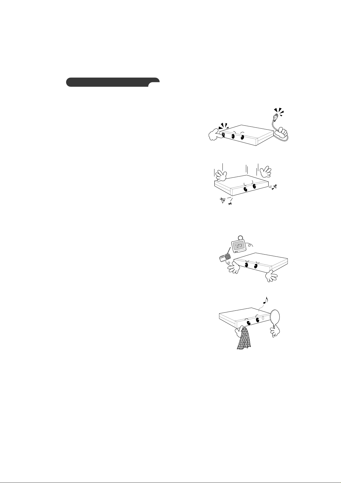
Cautions in Installation
Be aware of the following cautions when installing SNS-110.
● Always turn the power off before SNS-110 installation.
● Severe impact or vibration may cause malfunction.
● Avoid places with strong magnetic or electric field, or places near a radio or TV.
● Always keep the place dust-free when installing or moving SNS-110.
12
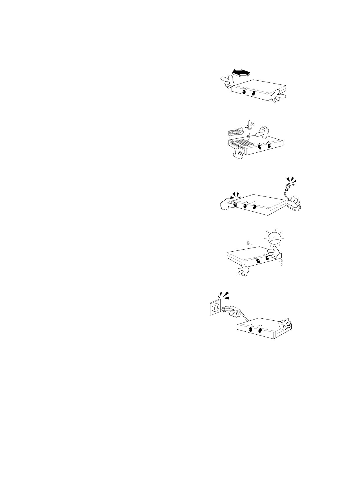
● Position it in an open space with flat surface, keeping the
aptitude temperature.
Also, maintain the clearance between back of the main body and the wall.
● Be careful not to insert accidentally any conducting material
in the ventilation space of product.
● Turn the power off and disengage the power cord from the body,
when changing the circuit-protecting fuse.
● Avoid a direct ray of light, and keep the safe distance between
crowded place and the product as well as its assemblies.
● The bottom surface must be moisture-free.
And, be cautious about any possible delicate factors,
such as ungrounded extension cable, abraded power cord,
lack of safe grounding.
15Cm
13
Always use a dry cloth when cleaning this product. If the contamination is
serious, please wipe it first with a neutral detergent, then with a dry cloth.
Avoid using volatile material, such as alcohol, benzene, or sinner, when wiping
the surface, due to potential damage on the surface.
NOTE
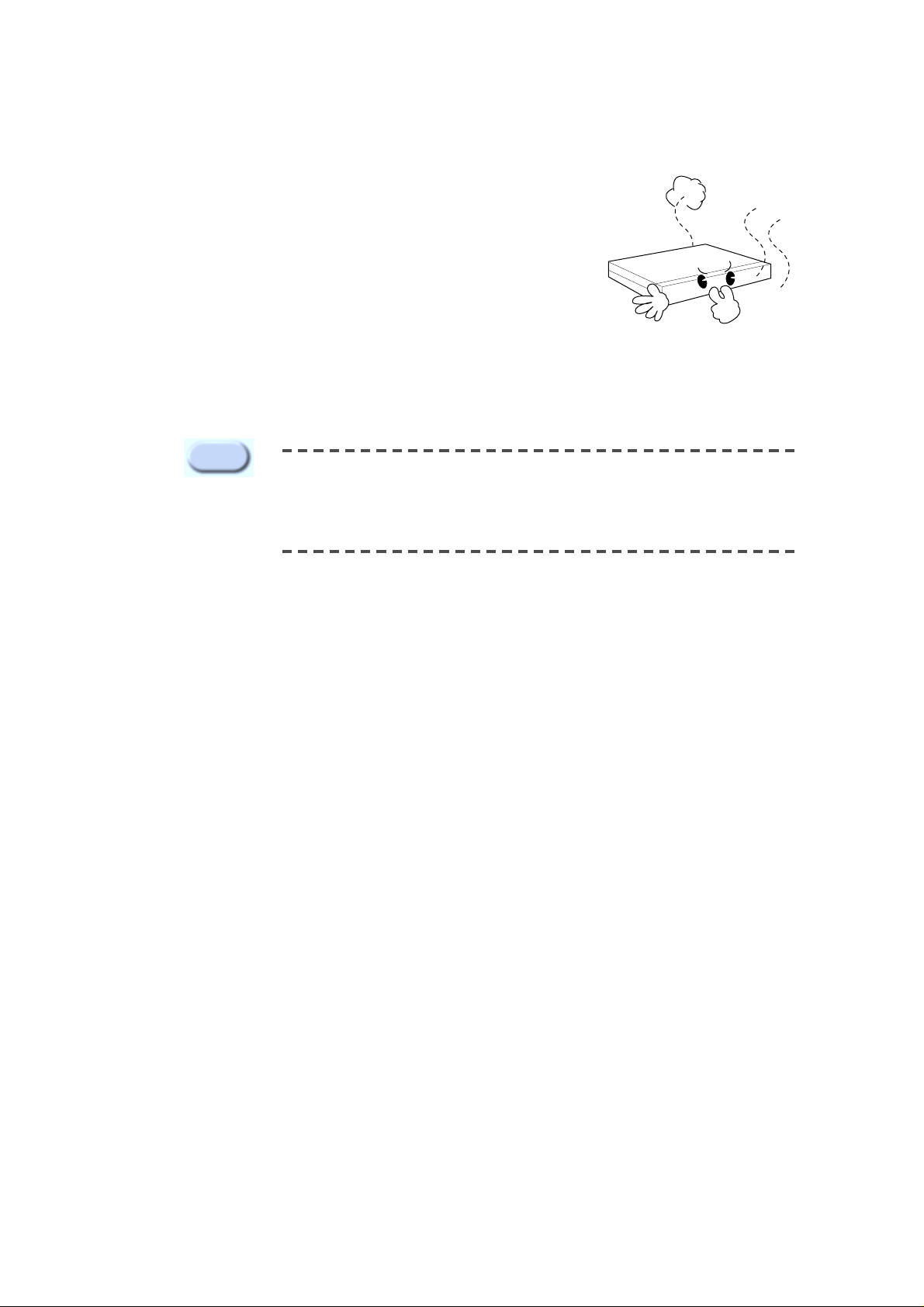
● Do not neglect fumes or unusual odor, which may be symptoms of malfunction.
When these are identified, please instantly disconnect the power
and consult to an expert from your local service center.

14
Unpacking
When you purchase SNS-110, after removing the wrap, place the product on a flat surface or where you
will be installing it.
Then, check if there is any missing part among the following items.
● SNS-110 Main Body
● User’s Guide
● Power Adapter (1EA)
● Power Cord (1EA)
● RS-232C Cable (1EA)
1
2
4
SNS-110 Main Body
RS-232C Cable (1EA)
User’s Guide
Power Adapter (1EA)
Power Cord (1EA)

You may connect the following items with SNS-110, such as video image players (e.g., VTR, DVDP, etc.,),
network devices, alarm sensors, PAN/TILT/ZOOM/FOCUS controllers, and PC-connected consoles.
Connecting to Camera and Video Image Player s (e.g., VTR, D VDP, TV)
SNS-110 automatically detects NTSC/PAL and transmits it as image signal. Therefore, you may connect
cameras and video image players (e.g., VTR, DVDP, etc.,) to video terminal 1~4.
15
Chapter 3. Connecting to Instruments
Caution
Caution
Video image players are preferred with identical system when connecting to
Video In/Out 1~4. The miscellaneous usage may decrease the resolution of
certain broadcasting system.
No voltage, more than DC 2V, must be connected to the video in/output
terminal 1~4.
CAMERA
VTR, DVDP, TV
OUT
3
4
1.CONTROL 2.F/H 3.Tx R 4.Rx R

16
SNS-110 produces the video image signal of the corresponding channel, if connected with external
instruments to Video Out 1~4 (loop through BNC). The terminal resistance of 75Ω will be automatically
seized by the connection with external instruments.
OUT
VTR, DVDP, TV
VIDEO IN
External Device
3
4
1.CONTROL 2.F/H 3.Tx R 4.Rx R
Connecting to External Instruments
External Device
Surveillance control units : Frame Switcher, Quad Switcher, Sequential Switcher, Multi-plexer, Monitor, etc.
CAMERA

17
Cable Modem
RS-232C
ETHERNET
DC 5V
ALARM IN
R/O RX
TX
1 2 3 4 - + - +
RA
RC
GG
RS-232C
ETHERNET
DC 5V
ALARM IN
R/O RX
TX
1 2 0 3 4 0 - + - +
RA
RC
RJ- 45 Ethernet Cable(Direct)
RJ- 45 Ethernet Cable(Direct)
Cable Modem
Cable Network
CMTS
(Cable Modem Termination System)
HUB
Back Bone
Back Bone
INTERNET
INTERNET
Connecting to Network
Ethernet(10BaseT/100BaseT)

18
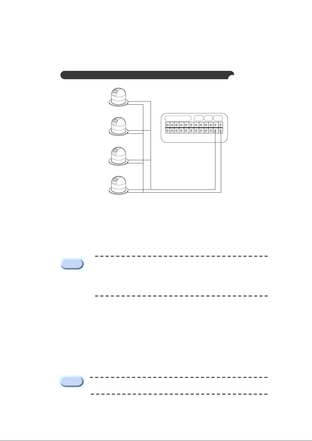
Connecting to Alarm Sensors and External Devices
S
E
N
S
O
R
1
S
E
N
S
O
R
2
S
E
N
S
O
R
3
S
E
N
S
O
R
4
G
N
D
G
N
D
ALARM IN
R/O RX
TX
1 2 3 4 - + - +
RA
RC
GG
Function Name Regular Capacity
Alarm In
Relay Out
Alarm 1/2/3/4/G
RA/RC
-TTL Level(5VDC)
-Initial Contact Resistance, Max. : 75m§
-Max. Switching Power : 60W, 62.5VA
-Max. Switching Voltage : 220VDC/125VAC
-Max. Carrying Current : 2A
-Contact Rating(Resistive) : 2A 30VDC/0.5A 125VAC
Alarm sensors and external devices are usable by connecting to ALARM IN and R/O terminals of the reverse
side of the SNS-110 respectively.
Caution
When connecting an external device to R/O terminal, you are recommended to use
additional “Relay” for the purpose of the protection of each device.
19
Connecting to PAN/TIL T/ZOOM/FOCUS Controller
The RX/TX terminal of the reverse side of the SNS-110 uses the RS-442/485 interface and
PAN/TILT/ZOOM/FOCUS controllers can be connected to the terminal.
The PAN/TILT/ZOOM/FOCUS controllers that are supported are the following.
●Samsung Smart-Dome Camera (SCC-641) ● Pelco : Pelco-P Protocol Support Control
●Sungjin Electronic Communications : CPU-Receiver
The TX+ and TX- of the terminal as shown in picture, is connected to the external terminal of the
PAN/TILT/ZOOM/FOCUS controller, and generally the external terminal has a +,- polarity indication so be
sure not to switch the polarity.
Set the F/H Switch to On (knob faced down) on the front side of the SNS-110.
Refer to the PAN/TILT/ZOOM/FOCUS controller manual and confirm & reset the following items.
● Baud Rate ● Data Bit
● Stop Bit ● Parity Bit
● Controller ID (be careful not to duplicate a different controller ID)
ALARM IN
R/O
RX
TX
1 2 3 4 - + - +
RA
RC
GG
P/T/Z/F Controller 1
P/T/Z/F Controller 2
P/T/Z/F Controller 3
P/T/Z/F Controller 4
When connecting Samsung Smart-Dome Camera (SCC-641), you have to connect the
SNS-110 to the TxDt, - terminals of SCC-641. In this case, the supportable Baud Rate
is 38400 and 19200bps. For more detail information, please refer to the user manual
of SCC-641.
Reference inquire the shop at which it was purchased for the products other
that the above PAN/TILT/ZOOM/FOCUS camera and controllers.
Note
RX-
RX+
RXRX+
RXRX+
RXRX+
If several PAN/TILT/ZOOM/FOCUS controllers are used, they must be the same
models.
Caution
20
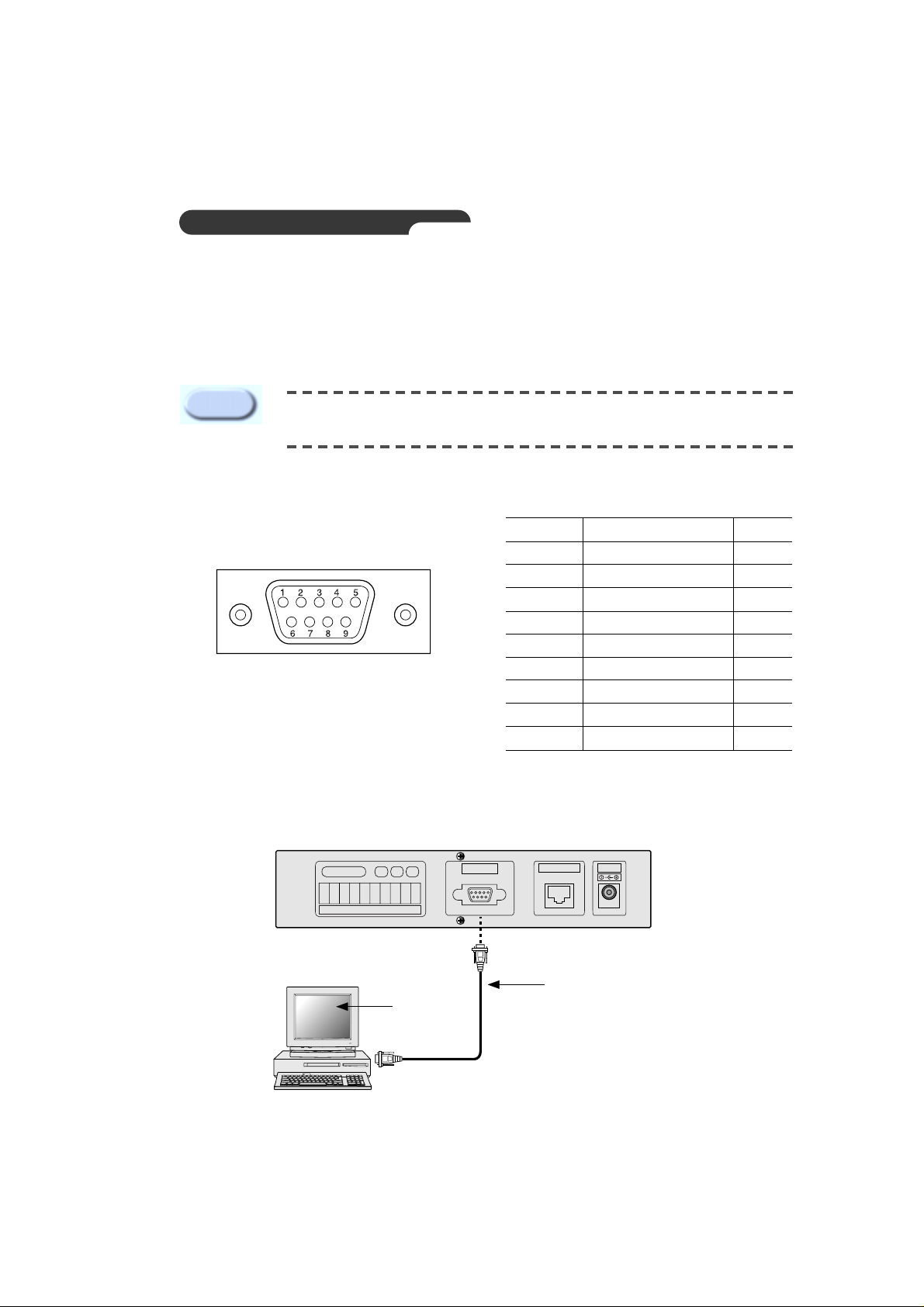
Connecting to RS-232C
When connecting PC serial port (COM1, COM2) through RS-232C from back of SNS-110, you may
select console mode of SNS-110 by using PC terminal emulation program (HyperTerminal).
Control S/W from the front panel must be positioned "OFF
".
RS - 232C T erminal (D-Sub 9Pin)
RS - 232C Connecting to Cable
RS-232C
ETHERNET
DC 5V
ALARM IN
R/O RX
TX
1 2 0 3 4 0 - + - +
RA
RC
Pin Number Name Direction
1NC
2 TxD(Transmit Data) Output
3 RxD(Receive Data) Input
4NC
5 SG(Signal GND) Power
6NC
7NC
8NC
9NC
RS - 232C Cable
Terminal
Emulation
Program
Serial Port
(COM1, COM2)
In the console mode, if you change the existing data improperly, the system
may result in serious problems.
Caution
21
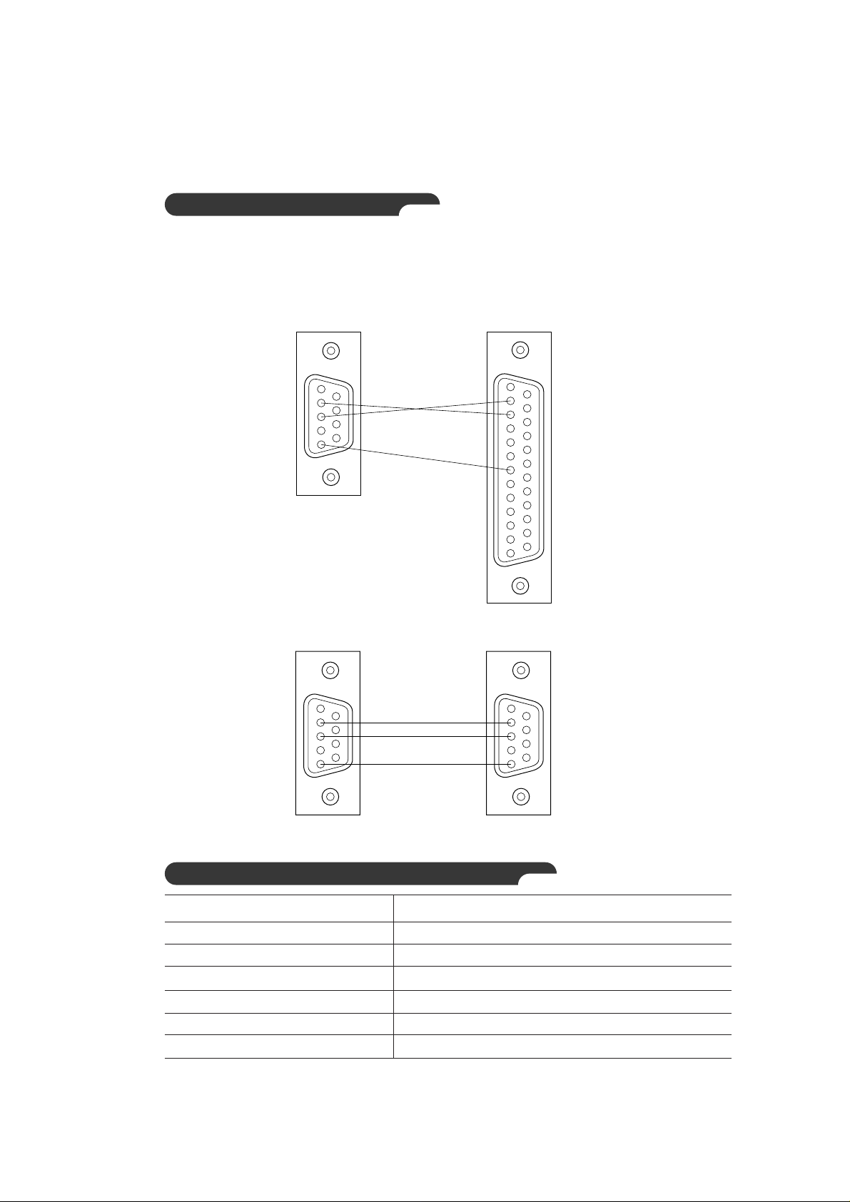
9Pin Female to 9Pin Female
T erminal Em ulation Communication Set-up
Items Contents
Baud Rate 38400 bps
Data Bit 8 Bit
Parity None
Stop Bit 1 Bit
Flow Control None
Data Code ASCII
1
2
3
5
9
6
1
2
3
5
9
6
Creating RS-232C Cable
The RS-232C Cable is packed with SNS-110, and so you don’t need to make it .
The wiring diagram shown below is for your information.
9Pin Female to 25Pin Female
1
2
3
5
1
6
9
14
2
3
7
25
13

22
RS-232C
ETHERNET
DC 5V
ALARM IN
R/O RX
TX
1 2 3 4 - + - +
RA
RC
GG
Connected from SNS-110 to PC(Twisted Cable)
RS-232C
ETHERNET
DC 5V
ALARM IN
R/O RX
TX
1 2 3 4 - + - +
RA
RC
GG
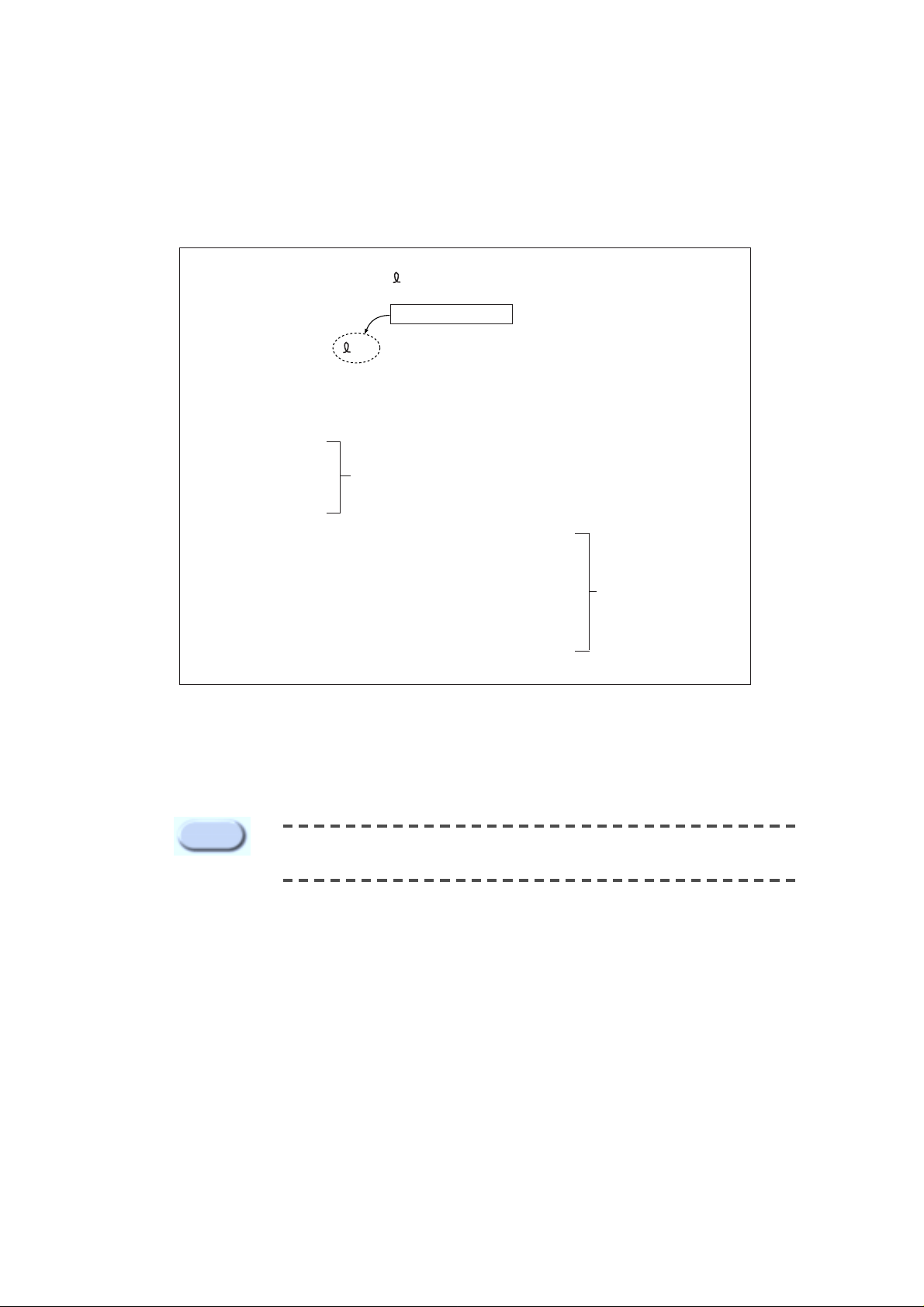
Creating Ethernet Cable
Since the Ethernet Cable is not packed with SNS-110, the user has to purchase and use it .
Direct
Ethernet Cable
HUB
Back Bone
INTERNET
Twisted
Ethernet Cable
Web Browser
LAN Card
RJ-45 Port
1
8
1
8
RJ - 45
RJ - 45
1
8
1
8
RJ - 45
RJ - 45
Web Browser
Connected from SNS-110 to Hub (Direct Cable)

23
Chapter 4 Setting an IP Address
Ethernet address (00-00-f0-XX-XX-XX) is recorded on the bottom of the
product at the time of purchase. Because it may be accidentally erased,
please duplicate the number and keep it somewhere else.
Caution
No information upon network is set up except Ethernet address (MAC address) in factory defaults. You
must set up the IP address when installing.
Before You Begin
(1) Confirm the Ethernet address (00-00-f0-XX-XX-XX) on the bottom of SNS-110. You must keep this
number for IP address set-up.
(2) Confirm the normal power supply of SNS-110.
(3) Confirm the proper connection with network.
When properly connected to network with Ethernet environment, the front network LED blinks.
(4) To use your SNS-110 under the Ethernet(10BaseT/100BaseT) environment, an unused IP address
must be assigned to SNS-110 from a network manager.
At this time, check the following network related information.
●IP Address
●Gateway
● Subnet Mask
● Domain Name
● DNS
(5) If you set up an IP address through DHCP server in network environment, and if SNS-110 is
properly connected to network, you will automatically be assigned with an IP address, gateway, and
subnet mask by turning the power on. Confirm this auto-assigned IP address from RS-232C
connected PC terminal emulation (HyperTerminal).
Please, refer to "Connecting to RS-232C"and APPENDIX C "How to Use Console
".
Refer to the Appendix D, "Dynamic IP information Transfer" to send Dynamically Assigned IP
Address to the administration server.
(6) Set up an IP address, according to network environment as following.
You must appropriately set up an IP address abiding by your network environment.

24
Setting In Ethernet (10BaseT/100BaseT)
For Windows 95/98/ME/NT/2000/XP
(1) Open Dos window from network-connected PC with SNS-110.
(2) Execute "arp -s".
(3) Confirm if the IP address completely agrees with Ethernet address as shown below by executing "arp -a".
If does not completely agree after pursuing (2), delete the present IP address by executing "arp -d"
and repeat (2) and (3).
arp -s <SNS-110 IP Address> <SNS-110 Ethernet Address>
Example :
arp -s 168.219.15.250 00-00-f0-ff-a1-0a
arp -a
Example :
arp -a
Internet Address Physical Address Type
168.219.15.249 00-00-f0-ff-a1-2b static
168.219.15.250 00-00-f0-ff-a1-0a static
arp -d <SNS-110 IP Address>
Example :
arp -d 168.219.15.250
25
(4) Wait until you receive the normal response after executing "ping".
(5) If you are getting no response, attempt 1~2 more times. If you are still not getting any response,
please refer to APPENDIX D "FAQ".
ping <SNS-110 IP Address> - 110 -n 20
Example :
ping 168.219.15.250 - 110 -n 20
Pinging 168.219.15.250 with 32 bytes of data:
Request timed out.
Request timed out.
Request timed out.
Request timed out.
Reply from 168.219.15.250: bytes=110 time=1ms TTL=255
Reply from 168.219.15.250: bytes=110 time=1ms TTL=255
Reply from 168.219.15.250: bytes=110 time=1ms TTL=255
Reply from 168.219.15.250: bytes=110 time=1ms TTL=255
Reply from 168.219.15.250: bytes=110 time=1ms TTL=255
Reply from 168.219.15.250: bytes=110 time=1ms TTL=255
No Response
Normal
Response
You must only use the PC within identical Gateway with IP address, when
setting up IP address in Ethernet.
Caution
You must enter it.
26
Setting in Unix
(1) Execute the following instruction for network-connected Unix machines with SNS-110.
(2) Execute "rarp -s".
(3)
Confirm if the IP address completely agrees with Ethernet address as shown below by executing "rarp - a".
If does not completely agree after pursuing (2), delete the present IP address by executing "rarp - d"
and repeat (2) and (3).
rarp -a
Example :
rarp -a
IP Address HW Type HW Address
168.219.15.249 10Mbps Ethernet 00-00-f0-ff-a1-2b
168.219.15.250 10Mbps Ethernet 00-00-f0-ff-a1-0a
rarp -d <SNS-110 IP Address>
Example :
rarp -d 168.219.15.250
rarp -s <SNS-110 IP Address> <SNS-110 Ethernet Address>
Example :
rarp -s 168.219.15.250 00:00:f0:ff:a1:0a

27
(4) See if you receive the normal response as shown below after executing
"
ping".
(5) If you do not get responses, type "Ctrl+C" to stop and try number (4) couple of more times to re-
execute. If you still do not get response, refer to the APPENDIX "D."
ping <SNS-110 IP Address>
Example :
ping 168.219.15.250
PING 168.219.15.250 (168.219.15.250): 56 data bytes
64 bytes from 168.219.15.250: icmp_seq=0 ttl=255 time=1.1ms
64 bytes from 168.219.15.250: icmp_seq=0 ttl=255 time=1.1ms
64 bytes from 168.219.15.250: icmp_seq=0 ttl=255 time=1.1ms
64 bytes from 168.219.15.250: icmp_seq=0 ttl=255 time=1.1ms
64 bytes from 168.219.15.250: icmp_seq=0 ttl=255 time=1.1ms
64 bytes from 168.219.15.250: icmp_seq=0 ttl=255 time=1.1ms
●
●
●
^c
You must only use the PC within identical gateway with IP address, when
setting up an IP address in Ethernet.
For detailed information, refer to
APPENDIX
E. FAQ "No response to PING
when setting the IP address".
Caution
 Loading...