

Page 1

NETWORK CAMERA
User Manual
SNP-3120/
3120V/3120VH
Page 2

Network Camera
User Manual
Copyright
©2011 Sams ung Techwin Co ., Ltd. All rig hts reser ved.
Trad em ark
The name of thi s product is the reg istered tradema rk of Samsung Techwin C o., Ltd.
Other trad emarks mention ed in this manual are t he registered trad emark of their res pective compan y.
Restriction
Samsung Techwi n Co., Ltd shall reser ve the copyrigh t of this document. U nder no circumst ances, this docu ment shall
be reproduc ed, distribute d or changed, par tially or wholly, wit hout formal auth orization of Sa msung Techwin.
Disclaimer
Samsung Techwi n makes the best to ve rify the integr ity and correc tness of the conte nts in this documen t, but no
formal guar antee shall be provi ded. Use of this do cument and the subs equent results sh all be entirely on the u ser’s own
responsib ility. Samsung Techwi n reserves the ri ght to change the con tents of this docu ment without pri or notice.
Warrant y
If the produ ct does not opera te properly in nor mal conditions, p lease let us know. S amsung Techwin will reso lve the
problem for f ree of charge. The wa rranty perio d is 3 years. However, the f ollowings are exclu ded:
• If the syste m behaves abnorma lly because you run a p rogram irreleva nt to the system ope ration.
• Deterior ated performa nce or natural worn -out in process o f time
Design an d specificat ions are subjec t to change wit hout prior not ice.
The defau lt password c an be exposed to a h acking threa d so it is recommen ded to change th e password
after in stalling the p roduct.
Note that t he security a nd other relat ed issues caus ed by the unchan ged password s hall be respon sible
for the user.
is the regist ered logo of Samsun g Techwin Co., Ltd.
Page 3
overview
IMPORTANT SAFETY INSTRUCTIONS
1. Read these instructions.
2. Keep these instructions.
3. Heed all warnings.
4. Follow all instructions.
5. Do not use this apparatus near water.
6. Clean only with dry cloth.
7. Do not block any ventilation openings, Install in accordance with the manufacturer’s
instructions.
8. Do not install near any heat sources such as radiators, heat registers, stoves, or other
apparatus (including amplifiers) that produce heat.
9. Do not defeat the safety purpose of the polarized or grounding-type plug. A polarized
plug has two blades with one wider than the other. A grounding type plug has two
blades and a third grounding prong. The wide blade or the third prong are provided for
your safety, If the provided plug does not fit into your outlet, consult an electrician for
replacement of the obsolete outlet.
10. Protect the power cord from being walked on or pinched particularly at plugs, conve-
nience receptacles, and the point where they exit from the apparatus.
11. Only use attachments/ accessories specified by the manufacturer.
12. Use only with the cart, stand, tripod, bracket, or table specified by
the manufacturer, or sold with the apparatus. When a cart is used,
use caution when moving the cart/apparatus combination to avoid
injury from tip-over.
13. Unplug this apparatus during lighting storms or when unused for
long periods of time.
Refer all servicing to qualified service personnel. Servicing is required when the apparatus
14.
has been damaged in any way, such as power-supply cord or plug is damaged, liquid has
been spilled or objects have fallen into the apparatus, the apparatus has been exposed to
rain or moisture, does not operate normally, or has been dropped.
● OVERVIEW
English _3
Page 4

overview
WARNING
TO REDUCE THE RISK OF FIRE OR ELECTRIC SHOCK, DO NOT EXPOSE
THIS PROCUCT TO RAIN OR MOISTURE. DO NOT INSERT ANY METALLIC
OBJECT THROUGH THE VENTILATION GRILLS OR OTHER OPENNINGS
ON THE EQUIPMENT.
Apparatus shall not be exposed to dripping or splashing and that no objects
filled with liquids, such as vases, shall be placed on the apparatus.
CAUTION
CAUTION
RISK OF ELECTRIC SHOCK.
DO NOT OPEN
CAUTION
REFER SERVICING TO QUALIFIED SERVICE PERSONNEL.
: TO REDUCE THE RISK OF ELECTRIC SHOCK.
DO NOT REMOVE COVER (OR BACK).
NO USER SERVICEABLE PARTS INSIDE.
EXPLANATION OF GRAPHICAL SYMBOLS
The lightning flash with arrowhead symbol, within an
equilateral triangle, is intended to alert the user to the
presence of “dangerous voltage” within the product’s
enclosure that may be of sufficient magnitude to constitute a
risk of electric shock to persons.
The exclamation point within an equilateral triangle is intended
to alert the user to the presence of important operating
and maintenance (servicing) instructions in the literature
accompanying the product.
4_ overview
Page 5

When used outside of the U.S., it may be used HAR code with fittings of
an approved agency is employed.
CAUTION
These servicing instructions are for use by qualified service personnel only.
To reduce the risk of electric shock do not perform any servicing other than
that contained in the operating instructions unless you are qualified to do so.
The BNC Out terminal of the product is provided for easier installation, and is
not recommended for monitoring purposes.
If you keep the BNC cable connected, a risk of lightening may cause damage
or malfunction to the product.
Please use the input power with just one camera and other devices must not
be connected.
Do not expose the product to the direct airflow from an air conditioner.
Otherwise, it may cause moisture condensation inside the Clear Dome due to
temperature difference between internal and external of the dome camera.
If you install this product in a low-temp area such as inside a cold store, you
must seal up the wiring pipe with silicon, so that the external air can not flow
inside the housing.
Otherwise, external high, humid air may flow inside the housing, pooling
moisture or vapor inside the product due to a difference between internal and
external temperature.
● OVERVIEW
English _5
Page 6
overview
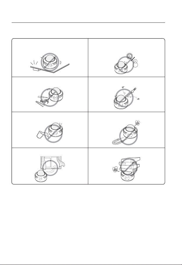
Please read the following recommend safety precautions carefully.
Do not place this apparatus on an uneven surface. Do not install on a surface where it is exposed to direct
Do not place this apparatus near conductive material. Do not attempt to service this apparatus yourself.
Do not place a glass of water on the product. Do not install near any magnetic sources.
Do not block any ventilation openings. Do not place heavy items on the product.
User’s Manual is a guidance book how to use the products
The meaning of the using sign in the book is following
Reference : In case of providing information for helping of product’s usages
Notice : If there’s any possibility to occur any damages for the goods and
human caused by not following the instruction
Please read this manual for the safety before using of goods and keep it in
the safe place.
sunlight, near heating equipment or heavy cold area.
6_ overview
Page 7
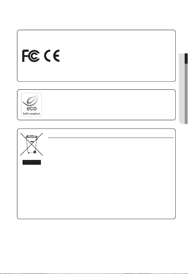
This equipment has been tested and found to comply with the limits for a
Class A digital device, pursuant to part 15 of the FCC Rules. These limits are
designed to provide reasonable protection against harmful interference when
the equipment is operated in a commercial environment.
This equipment generates, uses, and can radiate radio frequency energy and,
if not installed and used in accordance with the instruction manual, may cause
harmful interference to radio communications. Operation of this equipment in a
residential area is likely to cause harmful interference in which case the user will
be required to correct the interference at his own expense.
Samsung Techwin cares for the environment at all product manufacturing stages, and is
taking measures to provide customers with more environmentally friendly products.
The Eco mark represents Samsung Techwin’s devotion to creating environmentally friendly
products, and indicates that the product satisfies the EU RoHS Directive.
Correct Disposal of This Product (Waste Electrical & Electronic Equipment)
(Applicable in the European Union and other European countries with separate collection
systems)
This marking on the product, accessories or literature indicates that the product and its
electronic accessories (e.g. charger, headset, USB cable) should not be disposed of with other
household waste at the end of their working life. To prevent possible harm to the environment
or human health from uncontrolled waste disposal, please separate these items from other
types of waste and recycle them responsibly to promote the sustainable reuse of material
resources.
Household users should contact either the retailer where they purchased this product, or
their local government office, for details of where and how they can take these items for
environmentally safe recycling.
Business users should contact their supplier and check the terms and conditions of the
purchase contract. This product and its electronic accessories should not be mixed with other
commercial wastes for disposal.
● OVERVIEW
English _7
Page 8

overview
CONTENTS
OVERVIEW
3
INSTALLATION &
CONNECTION
18
NETWORK CONNECTION
AND SETUP
46
3 Important Safety Instructions
10 Product Features
10 Recomended PC Specifications
10 Recomended SDHC/SD Memory
Card Specifications
11 What’s Included
13 At a Glance
18 DIP Switch Setting
28 Installation (SNP-3120)
32 Installing with accessories (Sold
Separately)
34 Installation (SNP-3120V)
37 Installation (SNP-3120VH)
41 Inserting/Removing an SD
Memory Card
42 Memory Card Information
(Not Included)
43 Connecting with other Device
46 Connecting the Camera Directly
to Local Area Networking
47 Connecting the Camera Directly
to a DHCP Based DSL/Cable
Modem
48 Connecting the Camera Directly
to a PPPoE Modem
49 Connecting the Camera to an
IP Router with the PPPoE/Cable
Modem
50 Buttons used in IP Installer
51 Static IP Setup
54 Dynamic IP Setup
55 Port Range Forward (Port
Mapping) Setup
57 Connecting to the Camera from a
Shared Local PC
57 Connecting to the Camera from a
Remote PC via the Internet
8_ overview
Page 9

WEB VIEWER
58
58 Connecting to the Camera
59 Login
60 Installing Silverlight Runtime
62 Using the Live Screen
65 Playback
66 Playing the backup recordings
● OVERVIEW
CAMERA SETUP
67
SETUP SCREEN
80
APPENDIX
104
67 Using the Camera Menu
67 Camera Setting
77 OSD Setting
79 Initialize
80 Setup
80 Audio & Video Setup
88 Network Setup
93 Event Setup
99 System Setup
104 Specification
109 Product Overview
111 Troubleshooting
113 Open Source Announcement
115 GPL/LGPL Software License
English _9
Page 10

overview
PRODUCT FEATURES
Multi-Streaming
This network camera can display videos in different resolutions and qualities simultaneously using different CODECs.
However, MPEG4 video can not be played on a web page. Use CMS software if you want to play
M
the video on a web page.
Web Browser-based Monitoring
Using the Internet web browser to display the image in a local network environment.
Alarm
If an event occurs, the event-related video will be transferred to the email specified by the
user or saved to the SD memory, or the event signal will be sent to the Alarm Out port.
Intelligent Video Analysis
Analyzes the event video according to the user-specified rules to recognize the event.
ONVIF (Spec 1.02) Compliance
This product supports ONVIF Core Spec.
For more information, refer to www.onvif.org.
RECOMENDED PC SPECIFICATIONS
CPU : Intel(R) Core(TM)2 2.00 GHz or higher
Operating System : Windows XP, VISTA, 7
Resolution : 1280X1024 pixels or higher
RAM : 1GB or higher
Web Browser :
Video Memory : 128MB or higher
Mac OS
Internet Explorer 6.0 or higher
Firefox, Google Chrome, Safari
1.02.
RECOMENDED SDHC/SD MEMORY CARD SPECIFICATIONS
2GB ~ 32GB
To ensure proper recording of video data, we recommend you use a memory card that
supports at least read/write speed 10Mbps and Class 6.
10_ overview
Page 11
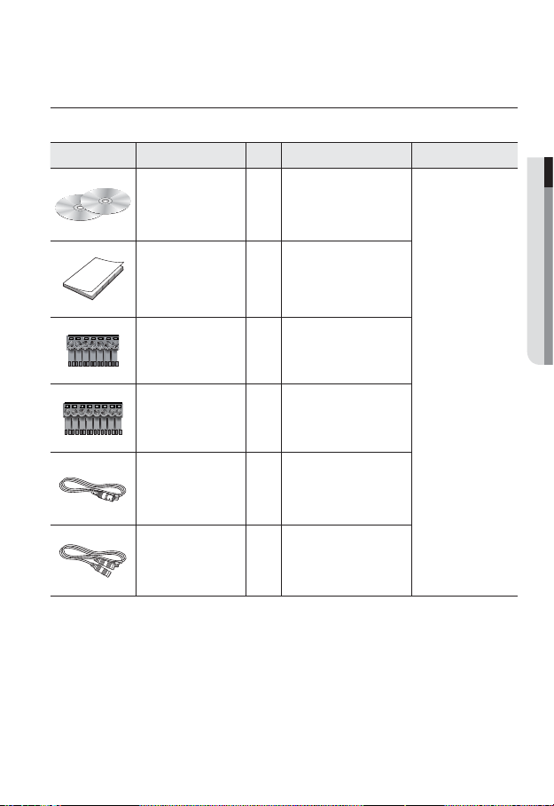
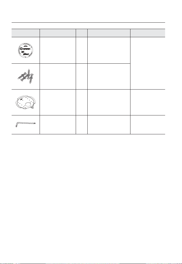
WHAT’S INCLUDED
Please check if your camera and accessories are all included in the product package.
Appearance Item Name
User Manual,
Installer S/W DVD,
CMS S/W DVD
Quick Guide 1
7Pin Terminal Block 1 For communications
8Pin Terminal Block 1 For alarm I/O
Quantity
2
Description Model Name
SNP-3120/3120V/
3120VH
● OVERVIEW
Cable for the testing
monitor
Audio cable 1
Used to test the camera
1
connection to a portable display
device
English _11
Page 12
overview
Appearance Item Name
Template 1 Product installation guide
ASSY-Tapping Screw
Mount Bracket
L Wrench
The Test Monitor Cable is connected to a portable displayer and used for testing the camera.
M
If you intend to use it for an actual monitoring camera, use the BNC cable instead.
Quantity
4
1
1
Description Model Name
Used for installation on the wall or
ceiling
Used to remove/fix the dome
cover
SNP-3120
SNP-3120
SNP-3120V/3120VH
12_ overview
Page 13
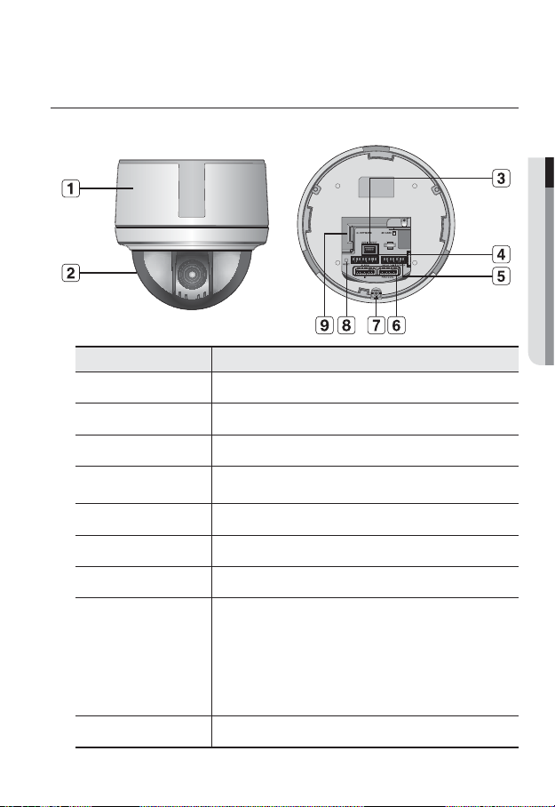
AT A GLANCE
❖SNP-3120
Item Description
Main unit Main unit includes the lens, switch board, PCB boards and screws.
Dome Cover Dome cover for the lens and unit protection.
b
Audio Audio I/O port.
c
Alarm In / Out
terminals
Video, RS-485, Power Used to connect monitor, RS-485 device or power.
ID setup switch Used to setup the camera ID or communication protocol.
Screw Hole Used to fix the camera to the wall or ceiling.
Reset Button
Network port Used to connect a PoE or LAN cable.
Used to connect alarm in/out terminal block.
Resets the camera settings to the default. Press and hold it for about 5
seconds to turn off the system indicator and restart the system.
If you reset the camera, the network settings will be adjusted so that
J
DHCP can be enabled. If there is no DHCP server in the network, you
must run the IP Installer program to change the basic network settings
such as IP address, Subnet mask, Gateway, etc., before you can
connect to the network.
● OVERVIEW
English _13
Page 14
overview
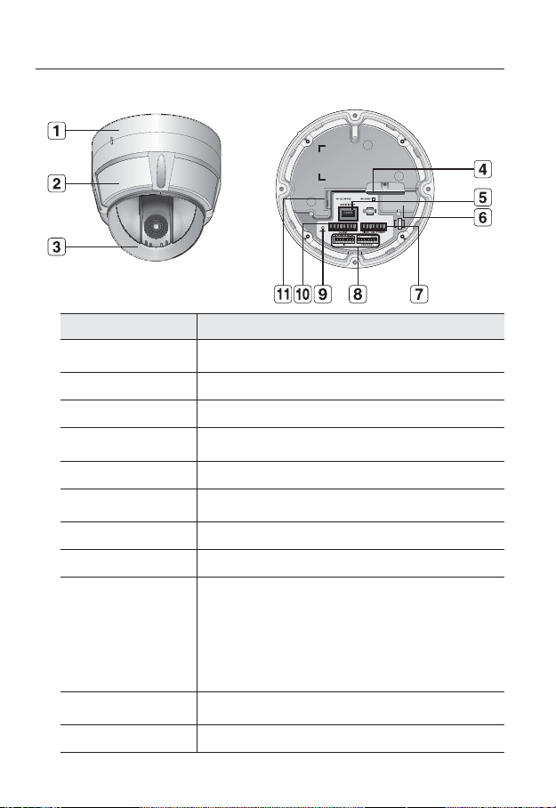
❖SNP-3120V
Item Description
Surface Mount
Bracket
Main unit Main unit includes the lens, switch board, PCB boards and screws.
b
Dome Cover Dome cover for the lens and unit protection.
c
SD Memory Card
Compartment
Audio Audio I/O port.
Heater
Video, RS-485, Power Used to connect monitor, RS-485 device or power.
ID setup switch Used to setup the camera ID or communication protocol.
Reset Button
Alarm In / Out
terminals
Network port Used to connect a PoE or LAN cable.
Used to install the camera directly on the ceiling.
After separating this cover, mount this bracket on to ceiling.
Compartment for the SD memory card.
Activated when the ambient temperature is under 5ºC to prevent the dome
cover from being covered with frost.
Resets the camera settings to the default. Press and hold it for about 5
seconds to turn off the system indicator and restart the system.
If you reset the camera, the network settings will be adjusted so that
J
DHCP can be enabled. If there is no DHCP server in the network, you
must run the IP Installer program to change the basic network settings
such as IP address, Subnet mask, Gateway, etc., before you can
connect to the network.
Used to connect alarm in/out terminal block.
14_ overview
Page 15
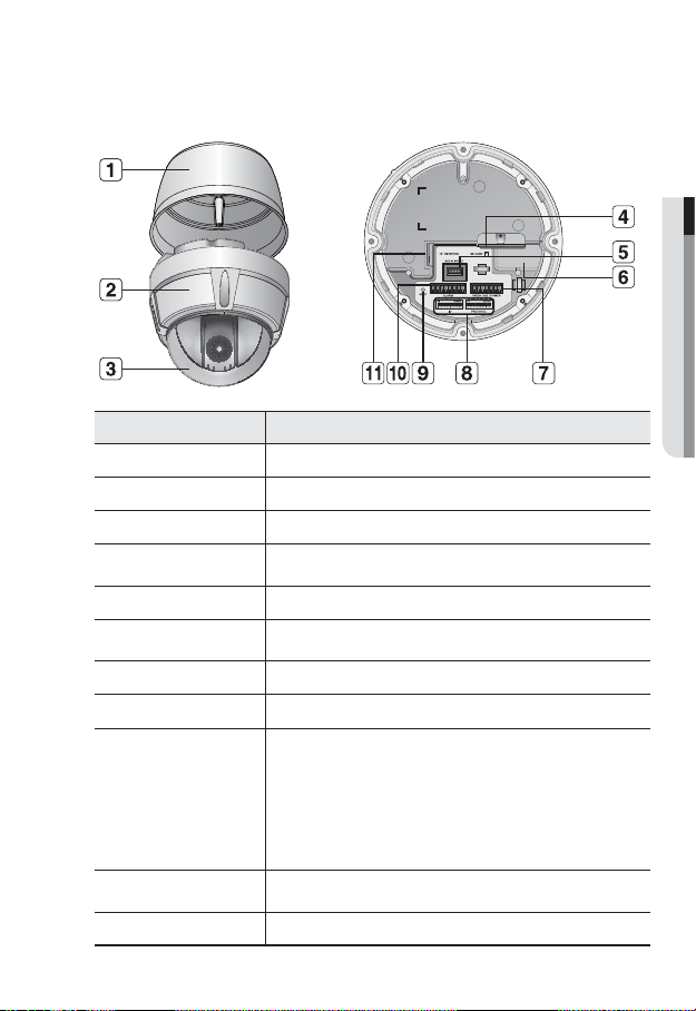
❖SNP-3120VH
Item Description
Sun Shield Housing Used to protect the main unit from the sunlight.
Main unit Main unit includes the lens, switch board, PCB boards and screws.
b
Dome Cover Dome cover for the lens and unit protection.
c
SD Memory Card
Compartment
Audio Audio I/O port.
Heater
Video, RS-485, Power Used to connect monitor, RS-485 device or power.
ID setup switch Used to setup the camera ID or communication protocol.
Reset Button
Alarm In / Out
terminals
Network port Used to connect a PoE or LAN cable.
Compartment for the SD memory card.
Activated when the ambient temperature is under 5ºC to prevent the dome
cover from being covered with frost.
Resets the camera settings to the default. Press and hold it for about 5
seconds to turn off the system indicator and restart the system.
If you reset the camera, the network settings will be adjusted so that
J
DHCP can be enabled. If there is no DHCP server in the network, you
must run the IP Installer program to change the basic network settings
such as IP address, Subnet mask, Gateway, etc., before you can
connect to the network.
Used to plug terminal block to connect alarm in/out.
● OVERVIEW
English _15
Page 16
overview
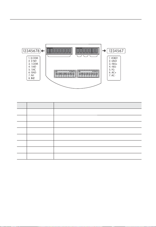
❖Camera Wiring Interface Board
For the camera wiring, please refer to the picture below. When using coaxial
communication, a separate control signal connection is not required.
ALARM
Controller & Auxiliary Signal Connection
No. Name Usage
1 2.COM Alarm Output 2 (Common)
2 2.NO Alarm Output 2 (Normal Open)
3 1.COM Alarm Output 1 (Common)
4 1.NO Alarm Output 1 (Normal Open)
5 1.NC Alarm Output 1 (Normal Open)
6 GND Ground
7 IN1 Alarm Input Sensor Terminal 1
8 IN2 Alarm Input Sensor Terminal 2
VIDEO 485 POWER
ID PROTOCOL
16_ overview
Page 17

Power, Video & Communication Signal Connection
No. Name Usage
1 VIDEO Video Output
2 GND Ground
3 485+ Controller Data Line
4 485- Controller Data Line
5FGField Ground
6ACAC 24V
7ACAC 24V
The provided BNC cable’s blue line is Video Output, while the black line is the Ground.
M
Power supply adaptor (AC) has no polarities.
The maximum power capacity of the built-in relay is 30V DC/2A, 125V AC/0.5A, and 250V
J
AC/0.25A.
Connecting the power connector and GND incorrectly to the NC/NO and COM ports may cause a
short circuit and fi re, damaging the camera.
When connecting the camera to an external over-rated product, use a separate relay device to
ensure proper operation.
To prevent possible inflow of lightning while in test monitoring, perform the test with the FG
terminal grounded.
● OVERVIEW
English _17
Page 18
installation & connection
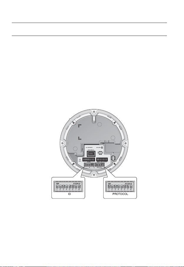
DIP SWITCH SETTING
How to set up Protocols and ID DIP Switches
You can control various settings of the camera system using the Communication and ID
DIP switches. Before installing the product, please set up the DIP switches according to the
installation environment.
1. Detach the camera frame from the install base, and place the bottom of the frame
toward you as shown in the picture below.
2. Set the switches according to your installation environment. For more detailed setup
information, please refer to the chart on the next page.
3. The camera may malfunction if the switches are not fully turned On/Off; please
double check the switches before finishing setup.
Camera ID DIP Switch(SW1)
18_ installation & connection
Communication Protocol
DIP Switch(SW2)
Page 19

Communication Protocol DIP Switch Settings (SW2)
Coaxial communication automatically detects signals, and so does not require a separate
communication setup process.
ON
SW2
Protocol Settings
Select a communication protocol for the camera.
No. Protocol SW2-#1 SW2-#2 SW2-#3 SW2-#4
1 AUTO DETECT OFF OFF OFF OFF
2 Samsung-T OFF OFF OFF ON
3 Pelco-D OFF OFF ON OFF
4 Pelco-P OFF OFF ON ON
5 Samsung-E OFF ON OFF OFF
6 Panasonic OFF ON OFF ON
7 Vicon OFF ON ON OFF
8 Honeywell OFF ON ON ON
9 AD ON OFF OFF OFF
10 GE ON OFF OFF ON
11 BOSCH ON OFF ON OFF
12 Reserved ON OFF ON ON
13 Reserved ON ON OFF OFF
14 Reserved ON ON OFF ON
15 Reserved ON ON ON OFF
16 Reserved ON ON ON ON
ON
SW2 Pin No. Purpose
OFF
1~4 Protocol Settings
5~6 Baud Rate Settings
7 Response Mode Settings
8 Termination Settings
● INSTALLATION & CONNECTION
English _19
Page 20

installation & connection
Baud Rate Settings
Select the transfer speed of a selected communication protocol.
No. Baud Rate (BPS) SW2-#5 SW2-#6
1 2,400 ON ON
2 4,800 ON OFF
3 9,600 OFF OFF
4 19,200 OFF ON
Communication Response Settings
Select a communication response method for the camera and controller: Response or No
Response.
Function ON OFF
SW2- #7 Response Mode Switch Response No Response
Termination Settings
To prevent the attenuation of communication signals between the camera and controller,
the items at the end of line must be set up with the termination settings.
Camera Input Position SW2- #8
Termination of Longest Path ON
On the Path OFF
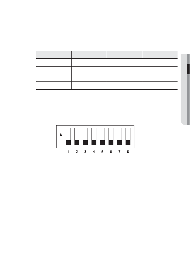
- This model is provided with factory defaults of all DIP switches set to OFF. The default
settings are shaded in the table.
20_ installation & connection
Page 21
To use a third party controller with this product, please contact our After-Sales Service or
M
Technology Department.
Controls Using Different Protocols
AD Protocol VICON Protocol GE Protocol
Entering Camera OSD 3+Auxilary ON IRIS OPEN IRIS OPEN
Exiting Camera OSD 3+Auxilary OFF IRIS CLOSE IRIS CLOSE
ENTER IRIS OPEN IRIS OPEN IRIS OPEN
ESC IRIS CLOSE IRIS CLOSE IRIS CLOSE
For more information about the protocols, refer to our official website.
Camera ID DIP Switch Settings (SW1)
To set up camera IDs, refer to the “Camera ID Chart” next.
● INSTALLATION & CONNECTION
ON
SW1
ON
OFF
English _21
Page 22

installation & connection
Camera ID Chart
ID SW1-#1 SW1-#2 SW1-#3 SW1-#4 SW1-#5 SW1-#6 SW1-#7 SW1-#8
1 ON/OFF OFF OFF OFF OFF OFF OFF OFF
2 OFF ON OFF OFF OFF OFF OFF OFF
3 ON ON OFF OFF OFF OFF OFF OFF
4 OFF OFF ON OFF OFF OFF OFF OFF
5 ON OFF ON OFF OFF OFF OFF OFF
6 OFF ON ON OFF OFF OFF OFF OFF
7 ON ON ON OFF OFF OFF OFF OFF
8 OFF OFF OFF ON OFF OFF OFF OFF
9 ON OFF OFF ON OFF OFF OFF OFF
10 OFF ON OFF ON OFF OFF OFF OFF
11 ON ON OFF ON OFF OFF OFF OFF
12 OFF OFF ON ON OFF OFF OFF OFF
13 ON OFF ON ON OFF OFF OFF OFF
14 OFF ON ON ON OFF OFF OFF OFF
15 ON ON ON ON OFF OFF OFF OFF
16 OFF OFF OFF OFF ON OFF OFF OFF
17 ON OFF OFF OFF ON OFF OFF OFF
18 OFF ON OFF OFF ON OFF OFF OFF
19 ON ON OFF OFF ON OFF OFF OFF
20 OFF OFF ON OFF ON OFF OFF OFF
21 ON OFF ON OFF ON OFF OFF OFF
22 OFF ON ON OFF ON OFF OFF OFF
23 ON ON ON OFF ON OFF OFF OFF
24 OFF OFF OFF ON ON OFF OFF OFF
25 ON OFF OFF ON ON OFF OFF OFF
26 OFF ON OFF ON ON OFF OFF OFF
27 ON ON OFF ON ON OFF OFF OFF
28 OFF OFF ON ON ON OFF OFF OFF
29 ON OFF ON ON ON OFF OFF OFF
30 OFF ON ON ON ON OFF OFF OFF
31 ON ON ON ON ON OFF OFF OFF
32 OFF OFF OFF OFF OFF ON OFF OFF
33 ON OFF OFF OFF OFF ON OFF OFF
34 OFF ON OFF OFF OFF ON OFF OFF
35 ON ON OFF OFF OFF ON OFF OFF
36 OFF OFF ON OFF OFF ON OFF OFF
37 ON OFF ON OFF OFF ON OFF OFF
38 OFF ON ON OFF OFF ON OFF OFF
39 ON ON ON OFF OFF ON OFF OFF
40 OFF OFF OFF ON OFF ON OFF OFF
41 ON OFF OFF ON OFF ON OFF OFF
22_ installation & connection
Page 23

ID SW1-#1 SW1-#2 SW1-#3 SW1-#4 SW1-#5 SW1-#6 SW1-#7 SW1-#8
42 OFF ON OFF ON OFF ON OFF OFF
43 ON ON OFF ON OFF ON OFF OFF
44 OFF OFF ON ON OFF ON OFF OFF
45 ON OFF ON ON OFF ON OFF OFF
46 OFF ON ON ON OFF ON OFF OFF
47 ON ON ON ON OFF ON OFF OFF
48 OFF OFF OFF OFF ON ON OFF OFF
49 ON OFF OFF OFF ON ON OFF OFF
50 OFF ON OFF OFF ON ON OFF OFF
51 ON ON OFF OFF ON ON OFF OFF
52 OFF OFF ON OFF ON ON OFF OFF
53 ON OFF ON OFF ON ON OFF OFF
54 OFF ON ON OFF ON ON OFF OFF
55 ON ON ON OFF ON ON OFF OFF
56 OFF OFF OFF ON ON ON OFF OFF
57 ON OFF OFF ON ON ON OFF OFF
58 OFF ON OFF ON ON ON OFF OFF
59 ON ON OFF ON ON ON OFF OFF
60 OFF OFF ON ON ON ON OFF OFF
61 ON OFF ON ON ON ON OFF OFF
62 OFF ON ON ON ON ON OFF OFF
63 ON ON ON ON ON ON OFF OFF
64 OFF OFF OFF OFF OFF OFF ON OFF
65 ON OFF OFF OFF OFF OFF ON OFF
66 OFF ON OFF OFF OFF OFF ON OFF
67 ON ON OFF OFF OFF OFF ON OFF
68 OFF OFF ON OFF OFF OFF ON OFF
69 ON OFF ON OFF OFF OFF ON OFF
70 OFF ON ON OFF OFF OFF ON OFF
71 ON ON ON OFF OFF OFF ON OFF
72 OFF OFF OFF ON OFF OFF ON OFF
73 ON OFF OFF ON OFF OFF ON OFF
74 OFF ON OFF ON OFF OFF ON OFF
75 ON ON OFF ON OFF OFF ON OFF
76 OFF OFF ON ON OFF OFF ON OFF
77 ON OFF ON ON OFF OFF ON OFF
78 OFF ON ON ON OFF OFF ON OFF
79 ON ON ON ON OFF OFF ON OFF
80 OFF OFF OFF OFF ON OFF ON OFF
81 ON OFF OFF OFF ON OFF ON OFF
82 OFF ON OFF OFF ON OFF ON OFF
83 ON ON OFF OFF ON OFF ON OFF
84 OFF OFF ON OFF ON OFF ON OFF
English _23
● INSTALLATION & CONNECTION
Page 24

installation & connection
ID SW1-#1 SW1-#2 SW1-#3 SW1-#4 SW1-#5 SW1-#6 SW1-#7 SW1-#8
85 ON OFF ON OFF ON OFF ON OFF
86 OFF ON ON OFF ON OFF ON OFF
87 ON ON ON OFF ON OFF ON OFF
88 OFF OFF OFF ON ON OFF ON OFF
89 ON OFF OFF ON ON OFF ON OFF
90 OFF ON OFF ON ON OFF ON OFF
91 ON ON OFF ON ON OFF ON OFF
92 OFF OFF ON ON ON OFF ON OFF
93 ON OFF ON ON ON OFF ON OFF
94 OFF ON ON ON ON OFF ON OFF
95 ON ON ON ON ON OFF ON OFF
96 OFF OFF OFF OFF OFF ON ON OFF
97 ON OFF OFF OFF OFF ON ON OFF
98 OFF ON OFF OFF OFF ON ON OFF
99 ON ON OFF OFF OFF ON ON OFF
100 OFF OFF ON OFF OFF ON ON OFF
101 ON OFF ON OFF OFF ON ON OFF
102 OFF ON ON OFF OFF ON ON OFF
103 ON ON ON OFF OFF ON ON OFF
104 OFF OFF OFF ON OFF ON ON OFF
105 ON OFF OFF ON OFF ON ON OFF
106 OFF ON OFF ON OFF ON ON OFF
107 ON ON OFF ON OFF ON ON OFF
108 OFF OFF ON ON OFF ON ON OFF
109 ON OFF ON ON OFF ON ON OFF
110 OFF ON ON ON OFF ON ON OFF
111 ON ON ON ON OFF ON ON OFF
112 OFF OFF OFF OFF ON ON ON OFF
113 ON OFF OFF OFF ON ON ON OFF
114 OFF ON OFF OFF ON ON ON OFF
115 ON ON OFF OFF ON ON ON OFF
116 OFF OFF ON OFF ON ON ON OFF
117 ON OFF ON OFF ON ON ON OFF
118 OFF ON ON OFF ON ON ON OFF
119 ON ON ON OFF ON ON ON OFF
120 OFF OFF OFF ON ON ON ON OFF
121 ON OFF OFF ON ON ON ON OFF
122 OFF ON OFF ON ON ON ON OFF
123 ON ON OFF ON ON ON ON OFF
124 OFF OFF ON ON ON ON ON OFF
125 ON OFF ON ON ON ON ON OFF
126 OFF ON ON ON ON ON ON OFF
127 ON ON ON ON ON ON ON OFF
24_ installation & connection
Page 25

ID SW1-#1 SW1-#2 SW1-#3 SW1-#4 SW1-#5 SW1-#6 SW1-#7 SW1-#8
128 OFF OFF OFF OFF OFF OFF OFF ON
129 ON OFF OFF OFF OFF OFF OFF ON
130 OFF ON OFF OFF OFF OFF OFF ON
131 ON ON OFF OFF OFF OFF OFF ON
132 OFF OFF ON OFF OFF OFF OFF ON
133 ON OFF ON OFF OFF OFF OFF ON
134 OFF ON ON OFF OFF OFF OFF ON
135 ON ON ON OFF OFF OFF OFF ON
136 OFF OFF OFF ON OFF OFF OFF ON
137 ON OFF OFF ON OFF OFF OFF ON
138 OFF ON OFF ON OFF OFF OFF ON
139 ON ON OFF ON OFF OFF OFF ON
140 OFF OFF ON ON OFF OFF OFF ON
141 ON OFF ON ON OFF OFF OFF ON
142 OFF ON ON ON OFF OFF OFF ON
143 ON ON ON ON OFF OFF OFF ON
144 OFF OFF OFF OFF ON OFF OFF ON
145 ON OFF OFF OFF ON OFF OFF ON
146 OFF ON OFF OFF ON OFF OFF ON
147 ON ON OFF OFF ON OFF OFF ON
148 OFF OFF ON OFF ON OFF OFF ON
149 ON OFF ON OFF ON OFF OFF ON
150 OFF ON ON OFF ON OFF OFF ON
151 ON ON ON OFF ON OFF OFF ON
152 OFF OFF OFF ON ON OFF OFF ON
153 ON OFF OFF ON ON OFF OFF ON
154 OFF ON OFF ON ON OFF OFF ON
155 ON ON OFF ON ON OFF OFF ON
156 OFF OFF ON ON ON OFF OFF ON
157 ON OFF ON ON ON OFF OFF ON
158 OFF ON ON ON ON OFF OFF ON
159 ON ON ON ON ON OFF OFF ON
160 OFF OFF OFF OFF OFF ON OFF ON
161 ON OFF OFF OFF OFF ON OFF ON
162 OFF ON OFF OFF OFF ON OFF ON
163 ON ON OFF OFF OFF ON OFF ON
164 OFF OFF ON OFF OFF ON OFF ON
165 ON OFF ON OFF OFF ON OFF ON
166 OFF ON ON OFF OFF ON OFF ON
167 ON ON ON OFF OFF ON OFF ON
168 OFF OFF OFF ON OFF ON OFF ON
169 ON OFF OFF ON OFF ON OFF ON
170 OFF ON OFF ON OFF ON OFF ON
English _25
● INSTALLATION & CONNECTION
Page 26

installation & connection
ID SW1-#1 SW1-#2 SW1-#3 SW1-#4 SW1-#5 SW1-#6 SW1-#7 SW1-#8
171 ON ON OFF ON OFF ON OFF ON
172 OFF OFF ON ON OFF ON OFF ON
173 ON OFF ON ON OFF ON OFF ON
174 OFF ON ON ON OFF ON OFF ON
175 ON ON ON ON OFF ON OFF ON
176 OFF OFF OFF OFF ON ON OFF ON
177 ON OFF OFF OFF ON ON OFF ON
178 OFF ON OFF OFF ON ON OFF ON
179 ON ON OFF OFF ON ON OFF ON
180 OFF OFF ON OFF ON ON OFF ON
181 ON OFF ON OFF ON ON OFF ON
182 OFF ON ON OFF ON ON OFF ON
183 ON ON ON OFF ON ON OFF ON
184 OFF OFF OFF ON ON ON OFF ON
185 ON OFF OFF ON ON ON OFF ON
186 OFF ON OFF ON ON ON OFF ON
187 ON ON OFF ON ON ON OFF ON
188 OFF OFF ON ON ON ON OFF ON
189 ON OFF ON ON ON ON OFF ON
190 OFF ON ON ON ON ON OFF ON
191 ON ON ON ON ON ON OFF ON
192 OFF OFF OFF OFF OFF OFF ON ON
193 ON OFF OFF OFF OFF OFF ON ON
194 OFF ON OFF OFF OFF OFF ON ON
195 ON ON OFF OFF OFF OFF ON ON
196 OFF OFF ON OFF OFF OFF ON ON
197 ON OFF ON OFF OFF OFF ON ON
198 OFF ON ON OFF OFF OFF ON ON
199 ON ON ON OFF OFF OFF ON ON
200 OFF OFF OFF ON OFF OFF ON ON
201 ON OFF OFF ON OFF OFF ON ON
202 OFF ON OFF ON OFF OFF ON ON
203 ON ON OFF ON OFF OFF ON ON
204 OFF OFF ON ON OFF OFF ON ON
205 ON OFF ON ON OFF OFF ON ON
206 OFF ON ON ON OFF OFF ON ON
207 ON ON ON ON OFF OFF ON ON
208 OFF OFF OFF OFF ON OFF ON ON
209 ON OFF OFF OFF ON OFF ON ON
210 OFF ON OFF OFF ON OFF ON ON
211 ON ON OFF OFF ON OFF ON ON
212 OFF OFF ON OFF ON OFF ON ON
213 ON OFF ON OFF ON OFF ON ON
26_ installation & connection
Page 27

ID SW1-#1 SW1-#2 SW1-#3 SW1-#4 SW1-#5 SW1-#6 SW1-#7 SW1-#8
214 OFF ON ON OFF ON OFF ON ON
215 ON ON ON OFF ON OFF ON ON
216 OFF OFF OFF ON ON OFF ON ON
217 ON OFF OFF ON ON OFF ON ON
218 OFF ON OFF ON ON OFF ON ON
219 ON ON OFF ON ON OFF ON ON
220 OFF OFF ON ON ON OFF ON ON
221 ON OFF ON ON ON OFF ON ON
222 OFF ON ON ON ON OFF ON ON
223 ON ON ON ON ON OFF ON ON
224 OFF OFF OFF OFF OFF ON ON ON
225 ON OFF OFF OFF OFF ON ON ON
226 OFF ON OFF OFF OFF ON ON ON
227 ON ON OFF OFF OFF ON ON ON
228 OFF OFF ON OFF OFF ON ON ON
229 ON OFF ON OFF OFF ON ON ON
230 OFF ON ON OFF OFF ON ON ON
231 ON ON ON OFF OFF ON ON ON
232 OFF OFF OFF ON OFF ON ON ON
233 ON OFF OFF ON OFF ON ON ON
234 OFF ON OFF ON OFF ON ON ON
235 ON ON OFF ON OFF ON ON ON
236 OFF OFF ON ON OFF ON ON ON
237 ON OFF ON ON OFF ON ON ON
238 OFF ON ON ON OFF ON ON ON
239 ON ON ON ON OFF ON ON ON
240 OFF OFF OFF OFF ON ON ON ON
241 ON OFF OFF OFF ON ON ON ON
242 OFF ON OFF OFF ON ON ON ON
243 ON ON OFF OFF ON ON ON ON
244 OFF OFF ON OFF ON ON ON ON
245 ON OFF ON OFF ON ON ON ON
246 OFF ON ON OFF ON ON ON ON
247 ON ON ON OFF ON ON ON ON
248 OFF OFF OFF ON ON ON ON ON
249 ON OFF OFF ON ON ON ON ON
250 OFF ON OFF ON ON ON ON ON
251 ON ON OFF ON ON ON ON ON
252 OFF OFF ON ON ON ON ON ON
253 ON OFF ON ON ON ON ON ON
254 OFF ON ON ON ON ON ON ON
255 ON ON ON ON ON ON ON ON
● INSTALLATION & CONNECTION
English _27
Page 28
installation & connection
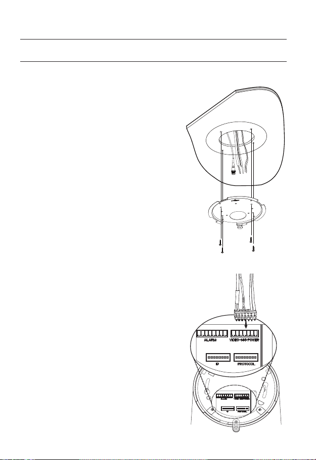
INSTALLATION (SNP-3120)
On-ceiling installation
1. Drill a hole of 60mm diameter on the ceiling
and run the wires down through it.
2. Install the Mount Bracket onto the hold and
fix it using 4 screws.
Do not connect the camera to a power outlet
J
until the installation is complete. Supplying power
in the middle of the installation may cause fire or
damage the product.
3.
Connect each camera cable to the proper
terminals on the bottom of the camera. For
more detailed instructions, please refer to
Page 16:“Camera Wiring Interface Board”.
4.
DIP switches for communication and ID setup
are located on the bottom of the camera. For
more instructions, please refer to Page 22.
28_ installation & connection
Page 29
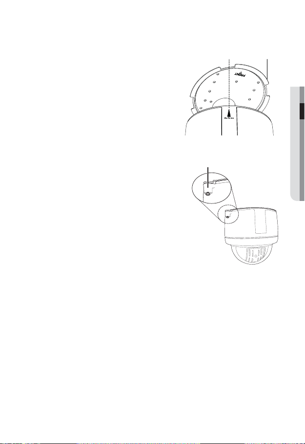
5.
Align the “Align The Arrow” triangular edge
of the camera to the marking (shown as “A” in
the diagram) on the left of the “FRONT” side
of the Mount Bracket.
6.
After inserting the camera into the Mount Bracket, turn the camera module clockwise about 25°.
7.
Match the screw holes in the camera and
mount bracket, and then fasten with the
screw.
Mount Bracket“A”
● INSTALLATION & CONNECTION
Screw Hole
English _29
Page 30
installation & connection
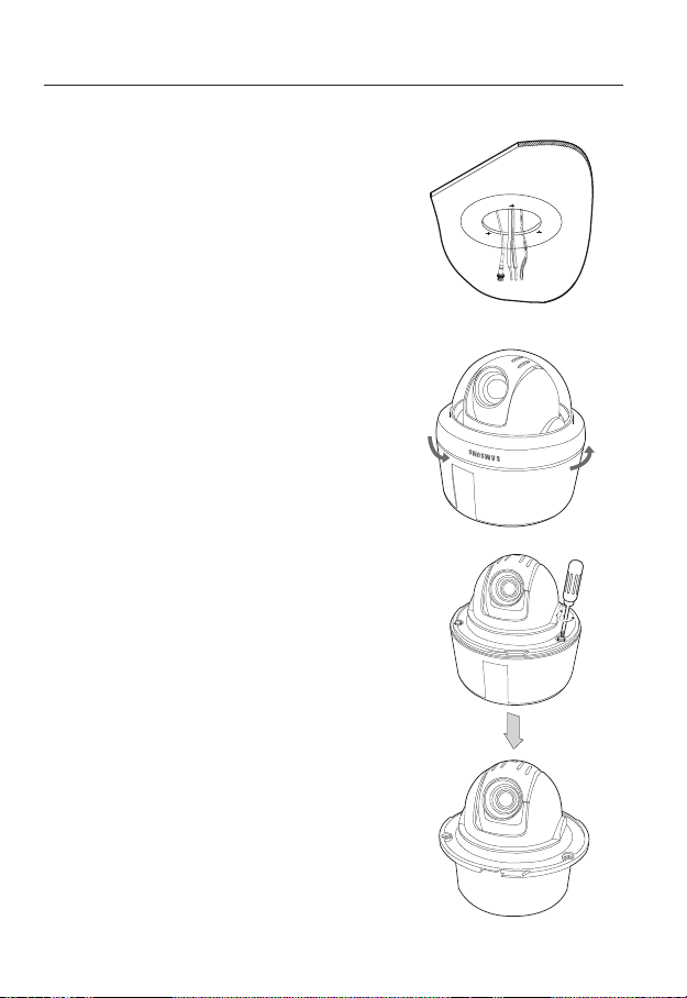
Flush Mount Type Installation Example
1. Attach the template, and then drill a hole
according to the 143 mm diameter hole
marked on the template. Drop down the
camera cables through the hole. Drill another
small hole for a screw to secure the camera.
2. Rotate the dome cover counterclockwise to
detach it from the camera.
3. Remove the 3 screws, and then detach the
mount housing from the camera.
30_ installation & connection
Page 31

4. Connect each camera cable to the proper ter-
minals on the bottom of the camera (Refer to
Page 16: “Camera Wiring Interface Board”).
Configure the DIP switches on the bottom of
the camera for communication and ID (Refer to
pages 19~21).
● INSTALLATION & CONNECTION
5. Install Camera Fit the camera to the hole on
the ceiling, and then secure the camera using 3
Product-enclosed Fixture Screws (M4x20).
6. Assemble Dome Cover Insert the grooves on the
dome cover into ones on the camera, and then
turn clockwise to fasten.
Screw
Ceiling
Screw
Ceiling
English _31
Page 32

installation & connection
INSTALLING WITH ACCESSORIES (SOLD SEPARATELY)
1. Turn the Dome Cover counter-clockwise
and separate from the camera.
Dome Cover
2. Remove 3 screws and separate the Mount Housing from the camera.
Mount Housing
32_ installation & connection
Page 33

3. Fix the Mount Housing onto the Hanging
Mount (SBP-300HM) with 4 screws (M4xL16).
Hanging
Note that the recommended torque for the screw
J
fastening is less than 3 kgf, to prevent
deformation of the mount housing.
4. Connect wires to the Terminal Block and attach it to the bot-
tom side of the camera.
(Refer to the “Camera Wiring Interface Board” at page 16.)
Set the communication protocol and ID DIP switches on the
bottom of the camera unit. (Refer to pages 19~21.)
5. Fix the camera to the Mount Housing by using 3 screws
removed in the step 2.
Mount
Mount Housing
● INSTALLATION & CONNECTION
6. Attach the Dome Cover and turn it clockwise to fix.
English _33
Page 34

installation & connection
INSTALLATION (SNP-3120V)
Ceiling Mount
1. Use the provided L-shaped wrench to remove the surface mount by loosening 4
screws counter clockwise.
Surface
Body
Screw
2. Drill holes (5 mm in diameter and at least 35 mm in depth for each) for the screws (x4)
to be inserted in the bottom of the surface mount, and insert the provided plastic
anchor (HUD5) to the end.
Insert the cables into the cable hole, and fix the SCREW-TAPPING (TH M4xL30) to
the plastic anchor that was inserted in the hole for fixing the surface mount. (x4)
Surface
Mount
34_ installation & connection
Page 35

3.
Connect the safety wire (attached to the camera) to the surface mount as shown.
Then, arrange the cables.
For more information about the wiring, refer to “Camera Wiring Interface Board”. (Page 16)
Safety-wire
Arrange the cables inside the surface mount so that they should not be entangled or stuck
4.
in, and align the guide rib of the camera with that of the surface mount. Use the L-shaped
wrench to tighten the screws (x4) so that the camera is secured to the mount.
To ensure waterproofness, take caution lest that the outer gasket should get loose or be
stuck in.
Guide Rib of
Surface Mount
Surface Mount
Guide-Rib of
Main-frame
● INSTALLATION & CONNECTION
Gasket
Screw
Main-frame
English _35
Page 36

installation & connection
Mount onto the optimal adaptor
1. Follow step 1 in “Ceiling Mount” above and remove the surface mount.
Insert the cables into the cable hole on the surface mount and fix them to SBP-300HM
2.
(HANGING MOUNT) using SCREW-MACHINE (BH, M4xL10, x4).
3. Repeat step 3 through step 4 in “Ceiling Mount” above to complete the installation.
36_ installation & connection
Page 37

INSTALLATION (SNP-3120VH)
1. Use the provided L-shaped wrench to loosen 4 screws counter clockwise, which will
help removing the housing.
Housing
Main-frame
Screw Screw
2.
Fix the housing to the NP 1.5" tapped pipe, wall mount (SBP-300WM) or ceiling
mount (SBP-300CM) by turning it clockwise. For waterproofness and lock between
the two component parts, use the Teflon tape to wrap them around.
● INSTALLATION & CONNECTION
Pipe or Mount
Housing
Pipe or Mount
NP 1.5' TAP
Housing
English _37
Page 38

installation & connection
3.
Secure the safety wire (attached to the product) to the housing as shown.
For details about the cable connection, refer to the “Camera Wiring Interface Board” section in this
manual.
Safety-wire
4.
Arrange the cables inside the housing lest they be damaged or stuck in, and use the
L-shaped wrench to tighten 4 screws to the housing. To ensure waterproofness, this
step needs your special care. Otherwise, the gasket on the outer side of the product
may be loose or just stuck in.
Housing
Main-frame
Gasket
38_ installation & connection
Safety-wire
Screw
Page 39

Optional Accessories for Installation
For your easier installation, you can purchase appropriate optional accessories available.
1. When installing the camera on a wall
SNP-3120, SNP-3120V :
Wall mount (SBP-300WM) + Hanging mount
(SBP-300HM)
SNP-3120VH :
Wall mount (SBP-300WM)
2. When installing the camera on a ceiling
SNP-3120, SNP-3120V :
Ceiling mount (SBP-300CM) + Hanging mount
(SBP-300HM)
SNP-3120VH :
Celling mount (SBP-300CM)
● INSTALLATION & CONNECTION
English _39
Page 40

installation & connection
3. When installing the Wall Mount (SBP-300WM) on
a pole bigger than 80mm in diameter :
Pole Mount (SBP-300PM)
4. When installing the Wall Mount (SBP-300WM) on a
cornered wall :
Corner Mount (SBP-300KM)
5. When installing SNP-3120VH on a rooftop of a
building :
Parapet Mount (SBP-300LM)
40_ installation & connection
Page 41

INSERTING/REMOVING AN SD MEMORY CARD
Inserting an SD Memory Card
Push the SD memory card in the direction of the arrow shown in the diagram.
Do not insert the SD memory card while it’s upside down by force. Otherwise, it may damage the
J
SD memory card.
Removing an SD Memory Card
Gently press down on the exposed end of the memory card as shown in the diagram to
eject the memory card from the slot.
● INSTALLATION & CONNECTION
Pressing too hard on the SD memory card can cause the card to shoot out uncontrollably from
J
the slot when released.
To remove the SD memory card, set <Record> to <Off> from <SD record> and press [Apply
( )]. (page 94)
If you have saved data in the SD memory card, removing the SD memory card prior to setting
record to OFF will cause damage to the data stored in the card.
English _41
Page 42

installation & connection
MEMORY CARD INFORMATION (NOT INCLUDED)
What is a memory card?
The memory card is an external data storage device that has been developed to offer an
entirely new way to record and share video, audio, and text data using digital devices.
Selecting a memory card that’s suitable for you
Your camera supports SDHC memory cards.
You may, however, experience compatibility issues depending on the model and make of
the memory card.
For your camera, we recommend you use a memory card from the following
manufacturers:
SDHC/SD Memory Card : Sandisk, Transcend, Kingston
Playback performance can be affected depending on the speed of memory card, so use
the high-speed memory card.
Memory Card Use
SD and SDHC memory cards feature a switch that disables writing data on to the media.
Having this switch to the Lock position will prevent accidental deletion of data stored in the
memory card but at the same time will also prevent you from writing data on to the media.
❖Memory Card Components
Contacts
Lock Switch
SD/SDHC
42_ installation & connection
Page 43

CONNECTING WITH OTHER DEVICE
Power
Monitor
Ethernet
Connecting to the monitor
Connect the video out port of the camera to the video input port of the monitor.
In the initial installation of the camera, you can connect the camera to the monitor for checking
M
the connection status.
Connect the monitor test cable to the output port of the monitor.
Ethernet Connection
Connect the Ethernet cable to the local network or to the Internet.
Power Supply
Use the screwdriver to connect each line (+, –) of the power cable to the corresponding
power port of the camera.
You can also use a router featuring PoE (Power over Ethernet) to supply power to the camera.
J
If using PoE, the heater will not operate at all. (SNP-3120V/VH)
Use an adaptor if the installation site requires heater operations. Adaptor is sold separately.
For the power specifications, refer to the “Appendix”. (page 108)
● INSTALLATION & CONNECTION
English _43
Page 44

installation & connection
Connecting to Audio Input/Output
Microphone
Microphone
Speaker
Speaker
Amp
Amp
Network
Microphone
PC
1. Connect the AUDIO IN port of the camera with the microphone directly or LINE OUT
port of the amplifier that the microphone is connected to.
2. Connect the AUDIO OUT port of the camera with the LINE IN port of the speaker.
3. Check the specifications for audio input.
Audio Codec
G.711 PCM. μ-law 64kbps 8kHz sampling
Full duplex Audio
Audio in
Used for mono signal line input (Max.2.4 Vpp)
Audio out
Used for mono signal line output (Max.2.4 Vpp)
Line out impedance
600
44_ installation & connection
Page 45

Alarm I/O Wiring Diagram
1 AUX COM
2
3
4
5
6
7
8
AUX NO
ALM1 COM
ALM1 NO
ALM1 NC
GND
ALM IN1
ALM IN2
Connecting to the I/O port box
Connect the Alarm I/O signal to the corresponding port of the rear port box.
1 2 3 4 5 6 7 8
1 : 2.COM 5 : 1.NC
2 : 2.NO 6 : GND
3 : 1.COM 7 : IN1
4 : 1.NO 8 : IN2
● INSTALLATION & CONNECTION
For further details on each terminal refer to “Camera Wiring Interface Board” (page 16)
M
English _45
Page 46

network connection and setup
You can set up the network settings according to your network configurations.
CONNECTING THE CAMERA DIRECTLY TO LOCAL AREA
NETWORKING
Connecting to the camera from a local PC in the LAN
1. Launch an Internet browser on the local PC.
2. Enter the IP address of the camera in the address bar of the browser.
Camera
INTERNET
Camera
Firewall
External Remote PC
Local PC
<Local Network>
A remote PC in an external Internet out of the LAN network may not be able to connect to the
M
camera installed in the intranet if the port-forwarding is not properly set or a firewall is set.
In this case, to resolve the problem, contact your network administrator.
By factory default, the IP address will be assigned from the DHCP server automatically. If there is
no DHCP server available, the IP address will be set to 192.168.1.100.
To change the IP address, use the IP Installer.
For further details on IP Installer use, refer to “Static IP Setup”. (Page 51)
46_ network connection and setup
DDNS Server
(Data Center, KOREA)
Page 47

CONNECTING THE CAMERA DIRECTLY TO A DHCP
BASED DSL/CABLE MODEM
Camera
DSL/Cable Modem
INTERNET
DDNS Server
(Data Center, KOREA)
External Remote PC
1. Use the cross LAN cable to connect the network cable directly to your PC.
2. Run the IP Installer and change the IP address of the camera so that you can use
the web browser on your desktop to connect to the Internet.
3. Use the Internet browser to connect to the camera.
4. Move to [Setup] page.
5. Move to [Network] – [DDNS] and configure the DDNS settings.
6. Move to [Network] – [Interface], and set the network type to [DHCP].
7. Connect the camera, which was removed from your PC, directly to the modem.
8. Restart the camera.
For registering the DDNS settings, refer to “Registering with DDNS”. (page 90)
M
For configuring the DDNS settings, refer to “DDNS”. (page 89)
For setting the network type, refer to “Interface”. (page 88)
●
NETWORK CONNECTION AND SETUP
English _47
Page 48

network connection and setup
CONNECTING THE CAMERA DIRECTLY TO A PPPOE
MODEM
Camera
1. Use the cross LAN cable to connect the network cable directly to your PC.
2. Run the IP Installer and change the IP address of the camera so that you can use
the web browser on your desktop to connect to the Internet.
3. Use the Internet browser to connect to the camera.
4. Move to [Setup] page.
5. Move to [Network] – [DDNS] and configure the DDNS settings.
6. Move to [Network] – [Interface], and set the network type to [PPPoE].
7. Connect the camera, which was removed from your PC, directly to the modem.
8. Restart the camera.
For registering the DDNS settings, refer to “Registering with DDNS”. (page 90)
M
For configuring the DDNS settings, refer to “DDNS”. (page 89)
PPPoE Modem
INTERNET
DDNS Server
(Data Center, KOREA)
External Remote PC
For setting the network type, refer to “Interface”. (page 88)
48_ network connection and setup
Page 49

CONNECTING THE CAMERA TO AN IP ROUTER WITH THE
PPPOE/CABLE MODEM
This is for a small network environment such as homes, SOHO and ordinary shops.
Camera
●
NETWORK CONNECTION AND SETUP
INTERNET
PPPoE or
Cable Modem
DDNS Server
(Data Center, KOREA)
External Remote
PC
Camera
Local PC
IP Router
PPPoE or
Cable Modem
Configuring the network settings of the local PC connected to an
IP router
Configuring the network settings of the local PC connected to an IP router, follow the
instructions below.
Select : <Network Neighborhood> <Properties> <Local Area Connection>
<Properties> <General> <Internet Protocol (TCP/IP)> <Properties>
<Obtain an IP address automatically> or <Use the following IP address>.
Follow the instructions below if you select <Use the following IP address>:
ex1) If the address (LAN IP) of the IP router is 192.168.1.1
IP address : 192.168.1.100
Subnet Mask : 255.255.255.0
Default Gateway : 192.168.1.1
ex2) If the address (LAN IP) of the IP router is 192.168.0.1
IP address : 192.168.0.100
Subnet Mask : 255.255.255.0
Default Gateway : 192.168.0.1
ex3) If the address (LAN IP) of the IP router is 192.168.xxx.1
IP address : 192.168.xxx.100
Subnet Mask : 255.255.255.0
Default Gateway : 192.168.xxx.1
For the address of the IP router, refer to the product’s documentation.
M
Refer to the “Port Range Forward (Port Mapping) Setup” section of the IP Router’s
documentation. (Page 55)
English _49
Page 50

network connection and setup
BUTTONS USED IN IP INSTALLER
Item Description
Device Name
Mode
b
MAC(Ethernet)
c
Address
IP Address
Protocol
UPnP Status This function is not currently implemented.
Model name of the connected camera.
Click the column to sort the list by model name.
However, search will be stopped if clicked during the search.
Displays either <Static> or <Dynamic> for the current network connection
status.
Ethernet address for the connected camera.
Click the column to sort the list by Ethernet address.
However, search will be stopped if clicked during the search.
IP address.
Click the column to sort the list by IP address.
However, search will be stopped if clicked during the search.
The factory default is “192.168.1.100”.
Network setting for the camera.
The factory default is “IPv4”.
Cameras with the IPv6 setting will be displayed “IPv6”.
50_ network connection and setup
Page 51

Item Description
URL
IPv4 Scans for cameras with the IPv4 setting.
IPv6 Scans for cameras with the IPv6 setting.
Search
Auto Set The IP Installer automatically configures the network settings.
Manual Set You should configure the network settings manually.
Exit Exits the IP Installer program.
m
For the IP installer, use only the installer version provided in the installation DVD or use the latest
M
one if available. You can download the latest version from the product website.
DDNS URL address enabling access from the external Internet.
However, this will be replaced with the <IP Address> of the camera if
DDNS registration has failed.
Scans for cameras that are currently connected to the network.
However, this button will be grayed out if neither IPv4 nor IPv6 is checked.
STATIC IP SETUP
Manual Network Setup
Run <IP Installer_vX.XX.exe> to display the camera search list.
At the initial startup, both [Auto Set] and [Manual Set] will be grayed out.
For cameras found with the IPv6 setting, these buttons will be grayed out as the cameras do not
M
support this function.
1. Select a camera in the search list.
Find the MAC (Ethernet) address
labeled on the rear of the camera.
Both the [Auto Set] and [Manual Set]
buttons will be activated.
2. Click [Manual Set].
The Manual Setting dialog appears.
The default values of <IP Address>,
<Subnet Mask>, <Gateway>, <HTTP Port> and <VNP Port> of the camera will
be displayed.
●
NETWORK CONNECTION AND SETUP
English _51
Page 52

network connection and setup
3. In the <Address> pane, provide the
necessary information.
MAC (Ethernet) Address : The MAC
(Ethernet) address of the applicable
camera will be set automatically so
you don't need to input it manually.
You can configure the static IP settings
M
only if the DHCP checkbox is unchecked.
If using an IP router
IP Address : Enter an address falling in
the IP range provided by the IP router.
ex) 192.168.1.2~254,
192.168.0.2~254,
192.168.XXX.2~254
Subnet Mask : The <Subnet Mask> of
the IP router will be the <Subnet Mask>
of the camera.
Gateway : The <Local IP Address> of
the IP router will be the <Gateway> of
the camera.
The settings may differ depending on the connected IP router model.
M
For more information, refer to the user manual of the applicable router.
Refer to the “Port Range Forward (Port Mapping) Setup” section of the IP Router’s
documentation. (Page 55)
If not using an IP router
For setting <IP Address>, <Subnet Mask>, and <Gateway>, contact your network administrator.
4. In the <Port> pane, provide
necessary information.
HTTP Port : Used to access the
camera using the Internet browser,
defaulted to 80. Use the spin button
to change the HTTP Port value.
VNP Port : Used to control the video
signal transfer, defaulted to 4520.
5. Enter the password.
This is the login password for the “admin” user who accesses the camera.
The default password is “4321”.
52_ network connection and setup
Page 53

The default password can be exposed to a hacking thread so it is recommended to change the
J
password after installing the product.
Note that the security and other related issues caused by the unchanged password shall be
responsible for the user.
6. Click [OK].
Manual network setup will be completed.
7. When the manual setup including IP is completed, the camera will restart.
If the IP router has more than one camera connected
Configure the IP related settings and the Port related settings distinctly with each other.
Category Camera #1 Camera #2
IP related settings
Port related settings
If the <HTTP Port> is set other than 80, you must provide the <Port> number in the address bar
M
of the Internet browser before you can access the camera.
ex) http://IP address : HTTP Port
IP Address
Subnet Mask
Gateway
HTTP Port
VNP Port
http://192.168.1.100:8080
192.168.1.100
255.255.255.0
192.168.1.1
8080
4520
192.168.1.101
255.255.255.0
192.168.1.1
8081
4521
Auto Network Setup
Run <IP Installer_vX.XX.exe> to display the camera search list.
At the initial startup, both [Auto Set] and [Manual Set] will be grayed out.
For cameras found with the IPv6 setting, these buttons will be grayed out as the cameras do not
M
support this function.
1.
Select a camera in the search list.
Find the MAC (Ethernet) address labeled
on the rear of the camera.
Both the [Auto Set] and [Manual Set]
buttons will be activated.
2. Click [Auto Set].
The Auto Setting dialog appears.
The <IP Address>, <Subnet Mask>,
and <Gateway> will be set automatically.
●
NETWORK CONNECTION AND SETUP
English _53
Page 54

network connection and setup
3. Enter the password.
This is the login password for the
“admin” user who accesses the
camera. The default password is
“4321”.
The default password can be exposed to
a hacking thread so it is recommended to
change the password after installing the
product.
Note that the security and other related issues
caused by the unchanged password shall be
responsible for the user.
4. Click [OK].
Auto network setup will be completed.
DYNAMIC IP SETUP
Dynamic IP Environment Setup
Example of the Dynamic IP environment
- If an IP router, with cameras connected, is assigned an IP address by the DHCP
server
- If connecting the camera directly to modem using the DHCP protocols
- If IPs are assigned by the internal DHCP server via the LAN
Checking the Dynamic IP
1.
Run the IP Installer on the user’s local
machine to display cameras allocated
with <Dynamic IP> addresses in the
list.
2. Select a camera in the list, and click
[Manual Set] to check the <Dynamic
IP> of the camera.
If you uncheck <DHCP>, you can
change IP or <Port> to <Static>.
54_ network connection and setup
Page 55

PORT RANGE FORWARD (PORT MAPPING) SETUP
If you have installed an IP router with a camera connected, you must set the port range
forwarding on the IP router so that a remote PC can access the camera in it.
Manual Port Range Forwarding
1. From the Setup menu of the IP router,
select <Applications & Gaming> <Port Range Forward>.
For setting the port range forward for
a third-party IP router, refer to the user
guide of that IP router.
2. Select <TCP> and <UDP Port> for
each connected camera to the IP
router.
Each port number for the IP router
should match that specified in
<Network> - <Port> from the camera's Setup menu.
When done, click [Save Settings].
3.
Your settings will be saved.
Above sample instructions are based on the CISCO’s IP Router (Model: LINKSYS).
M
The settings may differ depending on the connected IP router model.
For more information, refer to the user manual of the applicable router.
●
NETWORK CONNECTION AND SETUP
English _55
Page 56

network connection and setup
Setting up Port Range Forward for several network cameras
When several network camera connect to one IP router device, you should forward the
TCP 943 port of the router to the TCP 943 port of a connected camera.
If you don't set properly the TCP 943 port of the router, you cannot get any video stream from the
J
web page of the camera.
TCP 943 port is a port for the Silverlight policy server of a camera.
When Camera1 and Camera2 are connected to a router :
User Internet
Start End Protocol IP Address
943 943 TCP 192.168.1.100
3000 3000 TCP/UDP 192.168.1.100
3001 3001 TCP/UDP 192.168.1.101
4520 4520 TCP/UDP 192.168.1.100
4521 4521 TCP/UDP 192.168.1.101
8080 8080 TCP/UDP 192.168.1.100
8081 8081 TCP/UDP 192.168.1.101
You can set a rule of Port Forwarding on the IP router device through its configura-
tion web page.
You cannot change the Silverlight policy server port of a camera.
You can change the ports of the camera except the policy server port through its
configuration web pages.
56_ network connection and setup
Ù
IP router
Ú
Camera1 (192.168.1.100)
Web Server Port 8080
Ù
Ù
VNP Port 4520
RTSP Port 3000
Policy Server Port 943
Camera2 (192.168.1.101)
Web Server Port 8081
VNP Port 4521
RTSP Port 3001
Policy Server Port 943
Page 57

CONNECTING TO THE CAMERA FROM A SHARED LOCAL PC
1. Run the IP Installer.
It will scan for connected cameras and
display a list of them.
2. Double-click a camera to access.
The Internet browser starts and connects
to the camera.
Access to the camera can also be gained by typing the camera's IP address in the address bar of
M
the Internet browser.
●
NETWORK CONNECTION AND SETUP
CONNECTING TO THE CAMERA FROM A REMOTE PC VIA
THE INTERNET
Since using the IP Installer on a remote computer that is not in the IP Router’s network cluster
is not allowed, users can access cameras within an IP Router’s network by using the camera’s
DDNS URL.
1. Before you can access a camera in the IP router network, you should have set the
port range forward for the IP router.
2. From the remote PC, launch the Internet browser and type the DDNS URL address
of the camera, or the IP address of the IP router in the address bar.
ex) http://www.samsungipolis.com/[Product ID]
English _57
Page 58

web viewer
CONNECTING TO THE CAMERA
Normally, you would
1. Launch the Internet browser.
2.
Type the IP address of the camera in
the address bar.
ex) • IP address (IPv4) : 192.168.1.100
http://192.168.1.100
- the Login dialog should appear.
IP address (IPv6) : 2001:230:abcd:
•
ffff:0000:0000:ffff:1111
http://[2001:230:abcd:ffff:0000:0000:
ffff:1111]
If the HTTP port is other than 80
1. Launch the Internet browser.
2. Type the IP address and HTTP port number of the camera in the address bar.
ex) IP address : 192.168.1.100:HTTP Port number(8080)
http://192.168.1.100:8080 - the Login dialog should appear.
Using URL
1. Launch the Internet browser.
2. Type the DDNS URL of the camera in the address bar.
ex) URL address : http://www.samsungipolis.com/[Product ID]
- the Login dialog should appear.
58_ web viewer
Page 59

To check the DDNS address
If the camera is connected directly to the DHCP cable modem, DSL modem, or PPPoE
modem, the IP address of your network will be changed each time you try to connect to
the ISP (Internet Service Provider) server.
If this is the case, you will not be informed of the IP address changed by DDNS.
Once you register a dynamic IP-based device with the DDNS server, you can easily check
the changed IP when you try to access the device.
To add the IP address to the <DDNS> server, visit www.samsungipolis.com and register
your device, and set the DDNS option to <Samsung DDNS> before providing the host
name for the DDNS server.
LOGIN
The default user ID is “admin”, and the default password is “4321”.
1. Enter “admin” in the <User Name>
input box.
2.
Enter “4321” in the <Password> input
box.
If the password is changed, enter the
changed password instead.
3. Click [OK].
If you have logged in successfully, you
will the Live Viewer screen.
For security purposes, ensure that you
M
change the password in <System>
- <User>.
The administrator ID, “admin”, is fixed and can not be changed.
The default password can be exposed to a hacking thread so it is recommended to change the
password after installing the product.
Note that the security and other related issues caused by the unchanged password shall be
responsible for the user.
If you check the “
logged in automatically without being prompted to enter the login information.
Remember my password
” option when your input is done, in future you will be
● WEB VIEWER
If you are using Internet Explorer 7.0 or 8.0 as the default web browser, you can view the best
J
quality image with a screen ratio of 100%. Reducing the ratio may cut the image on the borders.
English _59
Page 60

web viewer
This network camera uses Microsoft Silverlight for displaying the video.
INSTALLING SILVERLIGHT RUNTIME
If your PC has not installed Silverlight Runtime or has just installed an old runtime version, you will
be redirected to the Silverlight Runtime installation page automatically when accessing the web
viewer.
1. Click <Click Here>.
2. When the file download dialog pops up,
click <Run>.
3. When the download is completed, click
<Run>.
4. The Silverlight Runtime installation page
will be displayed. <Install now> to proceed with the installation.
60_ web viewer
Page 61

5. When done, click <Close>.
6. Close and restart the web browser, and
try to access the Web Viewer.
When Silverlight Runtime is properly
installed, you will see the Live screen.
For normal installation, set the Block
J
Popup setting as follows:
Internet Explorer Tools Block
Popup Always allow popups from
the current site(A)
However, MAC OS X users who are not connected to the Internet can use the provided installation
DVD to install Silverlight Runtime (Run the executable “Silverlight_xxx.dmg” in the DVD. You will be
guided through installation of the software).
● WEB VIEWER
English _61
Page 62

web viewer
USING THE LIVE SCREEN
Item Description
Monitoring Move to the monitoring screen.
Playback Switch to the monitoring screen that plays recording data in the SD memory.
b
Setup Move to the Setup screen.
c
Viewer Screen Displays the Live video on the screen.
Alarm Output Activate the Alarm Out port.
Audio Display the audio Listen and Talk toggle button on the screen.
Hide the alarm
indicator
Camera Menu
62_ web viewer
Hides the alarm indicator near the border of the viewer screen.
Used to retrieve and customize the Camera Setup menu.
For selecting and saving each menu item, refer to “Using the Camera Menu”.
(page 67)
Page 63

Item Description
PTZ
Digital PTZ You can use the mouse wheel to activate the digital zooming.
Screen
Optimization,
Full Screen
Capture Saves the snapshot as an image file in the .bmp format.
Video Format
m
If the temperature drops below the operational range, video signal may not be produced. In such
M
cases, please wait for the video.
You can adjust the Pan/Tilt angle of the camera as well as the zoom factor.
Adjust the screen to the optimal size, and display the Full Screen icon on the Live
screen.
You can select a profile type in <Video profile> under the <Audio & Video> setup
menu.
MFor IE 6.0 users, press the Browse button next to the <Video profile> dialog
and select a profile type again if the selected profile is not played.
MIf the “Invalid codec” message is displayed, select a profile type from the profile
list again.
To capture the snapshot
1. Click [ ] on the scene to capture.
The Capture dialog should appear.
2. Click [Save] button.
The screenshot will be saved in the
specified path.
If you are using the IE8 as the default web
M
browser, select “Tools-Internet
Options-Security” and uncheck “Use
protected mode”.
● WEB VIEWER
English _63
Page 64

web viewer
To toggle the audio sound
1. Click the [Audio ( )] button.
The corresponding button will be displayed in the Viewer.
2. Click the button to listen to / mute the
sound as you wish.
This button operates as a toggle button.
To toggle the microphone sound
1. Click the [Mic ( )] button.
The corresponding button will be displayed in the Viewer.
“Cannot find audio recording device”
J
message appears if there is no
Microphone.
Click the button to start / stop talking.
2.
This button operates as a toggle button.
The Silverlight permission dialog appears when you click the microphone button.
To fit the full screen
1. Click the [Full Screen ( )] button.
The corresponding button will be displayed in the Viewer.
2. Click the button.
This will fit the Viewer to the full screen.
3. To exit the full screen mode, press [Esc] on the keyboard.
To control the PTZ
1. Press the [PTZ ( )] button.
2. When the PTZ button bar appears on
the screen, use the direction buttons to
adjust the camera angle, zoom factor
or focus to your preference.
For further details on PTZ use, refer to
M
“PTZ setup”. (page 83)
64_ web viewer
Page 65

To activate a preset
To perform the designated preset in the Live screen, right-click the mouse and select your
desired preset number.
PLAYBACK
1. Click the [Playback ( )] button.
2. Specify the start time and end time of
your search.
3. Select a search type.
4. Click the [Search (
The search results will be displayed in
the list.
If more than 500 events are recorded
M
within the search period, your search will
be limited up to the date when the 500th event is recorded.
For instance, if the search period is between 10th and 15th day of the month, and more than 800
events were recorded 10th through 11th, your search will be limited up to 11th day with a total of
800 events, and events after then (from 12th) will not be found.
5. Select a data item to play in the search
list.
6. Click the [Play ( )] button.
7. To stop playing the video, click [Stop
)].
(
To return to the search screen, click
[Exit (
)].
To check time information of the playing video
1. Click the [About ( )] button.
2. Date and time information appears on the screen.
)] button.
● WEB VIEWER
English _65
Page 66

web viewer
To back up the searched video
1. Click [ ] on the scene to back up.
Save as window appears.
2. Click [Save].
The screenshot will be backed up to the
specified path.
If you are using the IE8 as the default web
M
browser, select “Tools-Internet
Options-Security” and uncheck “Use
protected mode”.
PLAYING THE BACKUP RECORDINGS
You can play backup recordings by using the SlimPlayer.
To download SlimPlayer
1. Click [SlimPlayer ( )].
You will see a download dialog where
you can specify the download path.
2. Specify the path with a proper file name
and click [Save].
3. Unzip the downloaded file and run the
executable.
66_ web viewer
Page 67

camera setup
Main Me nu
Cam era Sett ing
P/T Set ting
OSD Set ting
Ini tial ize
USING THE CAMERA MENU
Follow the steps below if you run the Web Viewer for setting the menus.
1. Launch the Web Viewer.
2. Click [Camera Menu (
corner of the Live screen.
The camera setup menu appears.
3. Use the Up/Down (▲/▼) buttons to move
to a desired item.
4. Click [Enter ( )]. Then, use the up/
down (▲/▼) button to move to a desired
item.
5. To access a sub menu item, click
[Enter (
6. To move to previous menu or exit the menu setup, click [Cancel (
: This arrow appears next to a menu that contains sub items.
J
)].
If <IV analysis function> is enabled, camera’s OSD menu operation can be set as an event.
CAMERA SETTING
You can set up the general functions of camera module.
Starting the Menu
1. Click [Camera Menu ( )] button.
When main menu shows up on screen,
2.
move to desired menu by using direction
button.
)] in the left
Main Menu
Camera Setting
P/T Setting
OSD Setting
Initialize
● CAMERA SETUP
)] button.
English _67
Page 68

camera setup
Camera Setting
Zoo m/Fo cus
Whi te B alan ce ATW (IN)
Exp osure
Bac k Li ght OFF
AGC --DNR MED IUM
XDR OFF
Day /Nig ht
Oth ers
Zoom/Fo cus
Foc us M ode ONESH OT
Dig ital Zoo m OFF
Zoom/Focus
Main Menu Ö Camera Setting Ö Zoom/Focus
Focus Mode
- AUTO : Performs continuous auto-focus.
- MANUAL : Changes the camera mode to
Manual Focus.
- ONESHOT : Auto-focuses the camera
once after the Pan, Tilt, or Zoom
function is used.
Digital Zoom : Enables the maximum digital
Camera Setting
Zoom/Focus
White Balance ATW(IN)
Exposure
Back Light OFF
AGC --DNR MEDIUM
XDR OFF
Day/Night
Others
zoom. Setting the digital zoom to 16X provides a total zoom of 192X.
Unlike the optical zoom, the graphics quality
M
of the digital zoom decreases as its zoom
ratio increases.
Zoom/Focus
Focus Mode ONESHOT
Digital Zoom OFF
The auto-focus function may not operate
normally under the following conditions :
- When background illumination is low
- While Slow-Shutter is in operation
- If the zoom level is set too high
- When background illumination is too high
- If a long distance object and a close distance object appear together within a monitoring area
- If there is no contrast, e.g. Ceiling or a wall
- If the camera is facing a thin horizontal line
Auto Focus focuses on an object in the center of the screen; objects around the screen edges
may not be properly in focus.
68_ camera setup
Page 69

White Balance
Camera Setting
Zoo m/Fo cus
Whi te B alan ce
ATW(I N)
Exp osure
Bac k Li ght OFF
AGC --DNR MED IUM
XDR OFF
Day /Nig ht
Oth ers
The White Balance menu adjusts the balance of the screen colors under different lighting
conditions.
Main Menu Ö Camera Setting Ö White Balance
● CAMERA SETUP
ATW(IN) : Adjusts the screen color to be
optimal in an indoor environment.
(Operating Temperature: about 2,500°K ~
about 9,300°K)
ATW(OUT) : Automatically adjusts the
screen color to be optimal in bright outdoors environments. (Operating Temperature: about 2,000°K ~ about 10,000°K)
AWC : Adjusts the screen color to be op-
Camera Setting
Zoom/Focus
White Balance
Exposure
Back Light OFF
AGC --DNR MEDIUM
XDR OFF
Day/Night
Others
ATW(IN)
timized to the current lighting and monitor
conditions. Using this setting may require an readjustment if the lighting conditions
changes.
MANUAL : Enables customization of the Red and Blue gains.
White Balance may not work properly under the following conditions.
M
- When the color temperature of the environment surrounding the subject is out of the control
range.
- When the ambient illumination of the subject is dim.
- If the camera is directed towards a fluorescent light or is installed in a place where illumination
changes dramatically, White Balance adjustments may not deliver consistent results.
English _69
Page 70

camera setup
Exposur e
Bri ghtn ess 3 2
Iri s AUTO
Shu tter OFF
Sen s-Up AUT O
Camera Setting
Zoo m/Fo cus
Whi te B alan ce ATW (IN)
Exp osure
Bac k Li ght OFF
AGC --DNR MED IUM
XDR OFF
Day /Nig ht
Oth ers
Exposure
The Exposure settings are to control the camera’s exposure meter.
Main Menu Ö Camera Setting Ö Exposure
Brightness : Adjusts the screen
brightness.
(Over 32: Brighter, Under 32: Darker)
It may not fully operable under extremely low
lighting condition.
Iris
- AUTO : Automatically adjusts the exposure meter.
Camera Setting
Zoom/Focus
White Balance ATW(IN)
Exposure
Back Light OFF
AGC --DNR MEDIUM
XDR OFF
Day/Night
Others
- MANUAL : Enables manual
adjustment of the exposure meter.
(Over 32: Brighter, Under 32: Darker)
Shutter : Controls the camera’s electronic
shutter.
- OFF : The shutter speed is fixed at 1/60
for NTSC and 1/50 for PAL.
Exposure
Brightness 32
Iris AUTO
Shutter OFF
Sens-Up AUTO
Operates when Iris is on the Auto Mode.
- A. FLK : Select this setting when you
experience picture flickering.
Flickering can happen when artificial
lighting frequencies clash with camera frame rates.
- MANUAL : Enables manual adjustment of the shutter speed.
Sens-Up
- AUTO : Automatically detects light levels and maintains a clear picture at night or
under low-light conditions.
- Sens-Up Limit : Adjusts to the maximum-powered zoom per frame.
While the Internal Sync mode is in effect, setting the shutter to ‘---’ and facing the camera directly
M
to a bright light source may cause poor camera performance.
Brightness is disabled when the Iris is in Manual mode.
Shutter is disabled when the WDR is turned on.
Sens-Up is disabled when the shutter is in Manual mode.
70_ camera setup
Page 71

Back Light
Camera Setting
Zoo m/Fo cus
Whi te B alan ce ATW (IN)
Exp osure
Bac k Li ght
OF F
AGC --DNR MED IUM
XDR OFF
Day /Nig ht
Oth ers
Camera Setting
Zoo m/Fo cus
Whi te B alan ce ATW (IN)
Exp osure
Bac k Li ght
WDR
AGC --DNR MED IUM
XDR OFF
Day /Nig ht
Oth ers
WDR Set ting
Lim it MED IUM
Lev el 0 9
Backlight Mode Settings
Unlike other cameras, Samsung Techwin’s unique A1 DSP chip gives you a clear image of
the subject even with bright backlight.
Main Menu Ö Camera Setting Ö Back Light
● CAMERA SETUP
Back Light
- OFF : Disables the Backlight mode.
- WDR : Activates the Wide Dynamic
Range mode.
- BLC : Activates a user defined backlight
compensation mode.
Camera Setting
Zoom/Focus
White Balance ATW(IN)
Exposure
Back Light
OFF
AGC --DNR MEDIUM
XDR OFF
Day/Night
Others
WDR
When there are both bright and dark areas at the same time, this mode makes both areas
distinctive.
Main Menu Ö Camera Setting Ö Back Light Ö WDR
Limit : Three WDR sensitivity levels are
available in 3 : LOW, MEDIUM, and HIGH.
Note that the higher the sensitivity level,
the lower the contrast in the light and dark
areas becomes.
Level : Adjusts the screen brightness in
WDR mode.
WDR is disabled when the VPS mode is
M
turned on.
WDR is disabled if the Iris is in Manual mode.
During WDR operation, noise, discoloration,
spots, and whitish symptoms may occur
Camera Setting
Zoom/Focus
White Balance ATW(IN)
Exposure
Back Light
AGC --DNR MEDIUM
XDR OFF
Day/Night
Others
WDR Setting
Limit MEDIUM
Level 09
WDR
depending on lighting conditions. If they
occur, stop using WDR.
English _71
Page 72

camera setup
Camera Setting
Zoo m/Fo cus
Whi te B alan ce ATW (IN)
Exp osure
Bac k Li ght
BLC
AGC --DNR MED IUM
XDR OFF
Day /Nig ht
Oth ers
BLC
↑↑ : U p
: Down
←← : Left
: Righ t
W : De crease T : In creas e
Camera Setting
Zoo m/Fo cus
Whi te B alan ce ATW (IN)
Exp osure
Bac k Li ght OFF
AGC
-- DNR MED IUM
XDR OFF
Day /Nig ht
Oth ers
BLC
You can selectively choose a screen area to see objects within the area more clearly than
others.
Main Menu Ö Camera Setting Ö Back Light Ö BLC
You can adjust the position and size of the
backlight compensation area.
BLC is disabled if the Iris is in Manual mode.
M
Color saturation may occur depending on the
environment.
Camera Setting
Zoom/Focus
White Balance ATW(IN)
Exposure
Back Light
AGC --DNR MEDIUM
XDR OFF
Day/Night
Others
BLC
: Up ↓↓
: Down
: Left →→
: Right
W : Decrease T : Increase
BLC
AGC
AGC (Automatic Gain Control) adjusts the camera’s gain control and the screen brightness if
the camera has captured an object under low-light conditions.
Main Menu Ö Camera Setting Ö AGC
The OFF, LOW, MEDIUM, HIGH, and
MANUAL modes are available.
If you select the AUTO for Day/Night, you
M
cannot use the AGC menu.
Camera Setting
Zoom/Focus
White Balance ATW(IN)
Exposure
Back Light OFF
AGC
--DNR MEDIUM
XDR OFF
Day/Night
Others
72_ camera setup
Page 73

DNR (Dynamic Noise Reduction)
Camera Setting
Zoo m/Fo cus
Whi te B alan ce ATW (IN)
Exp osure
Bac k Li ght OFF
AGC --DNR
ME DIUM
XDR OFF
Day /Nig ht
Oth ers
Camera Setting
Zoo m/Fo cus
Whi te B alan ce ATW (IN)
Exp osure
Bac k Li ght OFF
AGC --DNR MED IUM
XDR
O FF
Day /Nig ht
Oth ers
DNR significantly reduces the amount of low luminance noise.
Main Menu Ö Camera Setting Ö DNR
OFF : Disables the noise reduction func-
tion.
LOW : Reduces only a small amount of
noise, but generates almost no
afterimage.
MEDIUM : The most commonly used
mode. Reduces a suitable amount of noise
while generating a subtle afterimage.
Camera Setting
Zoom/Focus
White Balance ATW(IN)
Exposure
Back Light OFF
AGC ---
DNR
MEDIUM
XDR OFF
Day/Night
Others
HIGH : Reduces noise significantly, but
generates obvious afterimages.
XDR (eXtended Dynamic Range)
XDR illuminates darker spots of an image while retaining the same light level for brighter
spots to even out the overall brightness of the image with high contrast between bright and
dark spots.
Main Menu Ö Camera Setting Ö XDR
The OFF, LOW, MEDIUM and HIGH modes
are available.
Camera Setting
Zoom/Focus
White Balance ATW(IN)
Exposure
Back Light OFF
AGC --DNR MEDIUM
XDR
OFF
Day/Night
Others
● CAMERA SETUP
English _73
Page 74

camera setup
Camera Setting
Zoo m/Fo cus
Whi te B alan ce ATW (IN)
Exp osure
Bac k Li ght OFF
AGC --DNR MED IUM
XDR OF F
Day /Nig ht
Oth ers
Day/Nig ht
Mod e AU TO
Dwe ll T ime 3 SEC
Day/Night
The Day & Night function allows the camera to switch between the Color and B/W modes.
Main Menu Ö Camera Setting Ö Day/Night
Mode
- AUTO : Operates in Color mode most times,
and switches to B/W mode if a low light level
is detected during nighttime.
- COLOR : Operates in Color mode at all
times.
- BW : Operates in B/W mode at all times.
By using the Burst On/Off sub menu,
burst signals can be retained or disabled.
Camera Setting
Zoom/Focus
White Balance ATW(IN)
Exposure
Back Light OFF
AGC --DNR MEDIUM
XDR OFF
Day/Night
Others
If the camera is in B/W mode and connected to equipment that requires external sync through burst
signals, set the Burst On/Off option to “On”.
Dwell Time : The duration of both the lighting
conditions can be customized to let the camera delay the switching between the daytime
and night-time settings.
Using B/W mode under sunlight or a halogen
M
lamp may decrease the focusing
performance.
Day/Night
Mode AUTO
Dwell Time 3 SEC
74_ camera setup
Page 75

Others
Camera Setting
Zoo m/Fo cus
Whi te B alan ce ATW (IN)
Exp osure
Bac k Li ght OFF
AGC --DNR MED IUM
XDR OF F
Day /Nig ht
Oth ers
Others
Sha rpne ss 2
Fre eze OFF
Sta bili zer OFF
VPS O FF
Pos i/Ne ga +
P/T Set ting
Ima ge H old
OFF
Jog Spe ed MA NUAL
Max Spe ed L evel 5
Main Menu Ö Camera Setting Ö Others
Sharpness : Sharpens outlines of an
image.
Freeze : Stops or reanimates an image.
Stabilizer : The Stabilizer compensates
for any small movements of the camera
caused by due to the wind and other
reasonable causes.
VPS : This function enhances the outline of
Camera Setting
Zoom/Focus
White Balance ATW(IN)
Exposure
Back Light OFF
AGC --DNR MEDIUM
XDR OFF
Day/Night
Others
moving subject, which improves the sharpness of a captured image as fine as a still
image.
Posi/Nega : Setting to + outputs normal
video, where setting to – outputs inverted
brightness and color.
The Stabilizer uses the digital zoom and may
M
cause low picture quality.
Others
Sharpness 2
Freeze OFF
Stabilizer OFF
VPS OFF
Posi/Nega +
The Stabilizer is disabled if the ambient light
is too low.
The Stabilizer is disabled if the field of view has very low or no contrast, e.g. The sky or a white wall.
VPS is disabled when the Freeze is turned on.
Image Hold
Main Menu Ö P/T Setting Ö Image Hold
When the camera is moving between
presets locations, this function freezes the
cameras image until the camera reached
the next location. This is useful to help the
screen observer keep sharp eyes and to
monitor multiple locations within a network.
P/T Setting
Image Hold
OFF
Jog Speed MANUAL
Max Speed Level 5
● CAMERA SETUP
English _75
Page 76

camera setup
P/T Set ting
Ima ge H old O FF
Jog Spe ed
MAN UAL
Max Spe ed L evel 5
P/T Set ting
Ima ge H old O FF
Jog Spe ed MA NUAL
Max Spe ed L evel
Jog Speed
You can adjust the pan/tilt speed of the controller in use.
Main Menu Ö P/T Setting Ö Jog Speed
MANUAL : The angle of the controller
handle determines the speed of Pan and
Tilt; the more you tilt the controller, the
faster the camera spins.
10/20/30/40/50/60 : Maintains speed
P/T Setting
Image Hold OFF
Jog Speed
MANUAL
Max Speed Level 5
regardless of the angle of the controller
handle.
Max Speed Level
Adjusts the maximum speed of Pan and Tilt while performing the Preset and Sequencing
actions.
Main Menu Ö P/T Setting Ö Max Speed Level
1~7 : Pan and Tilt operations can be set up
to 650°/ sec.
P/T Setting
Image Hold OFF
Jog Speed MANUAL
Max Speed Level 55
76_ camera setup
Page 77

OSD SETTING
Main Me nu
Cam era Sett ing
P/T Set ting
OSD Set ting
Ini tial ize
OSD Set ting
Cam era ID ON
Cam era Name
Seq . St atus ON
PTZ Pos itio n ON
Lan guag e ENGL ISH
Oth ers
Camera Name [ ]
AB CDE FGH IJK LM
NOP QRST UVWX YZ
a b c d e f g h ij k l m
n op q rs t u vw x y z
1 23 4 56 7 89 0 ( )
[]- /#*! ?,.
B ACK SPA CE CL R SE T
OSD Setting
OSD Setting is to set up the OSD (On Screen Display) functions.
Main Menu Ö OSD Setting
● CAMERA SETUP
Camera ID : Displays or hides Camera ID in
the upper left of the screen.
Camera Name : Add a name to the cam-
era.
Seq. Status : Displays or hides the status
of a sequence action that is in progress.
PTZ Position : Displays or hides the status
of the Pan, Tilt, and Zoom operation that is
in progress.
Language :
Enables changing the system
language. This camera supports English,
Chinese, French, German, Spanish, Portuguese, Korean and Italian.
When selecting the Camera Name and Preset
M
Name, the screen displays the Left keypad.
Names can be up to 12 characters and can
be entered via the joystick and the Enter key.
Once a name is entered, use the joystick and
the Enter key to perform the Set command
and save the name.
Main Menu
Camera Setting
P/T Setting
OSD Setting
Initialize
OSD Setting
Camera ID ON
Camera Name
Seq. Status ON
PTZ Position ON
Language ENGLISH
Others
Camera Name [ ]
ABCDEFGHIJKLM
NOPQRSTUVWXYZ
abcdefghijklm
nopqrstuvwxyz
1234567890 ( )
[]-/#*!?,.
BACK SPACE CLR SET
English _77
Page 78

camera setup
OSD Set ting
Cam era ID ON
Cam era Name
Seq . St atus ON
PTZ Pos itio n ON
Lan guag e ENGL ISH
Oth ers
OSD Set ting
Dir ectio n
Clo ck S etti ng
OSD Setting (Others)
Main Menu Ö OSD Setting Ö Others
Direction : Indicates the current angle of the
camera: East, West, South, North, Southeast, Southwest, Northeast, or Northwest.
- Set North Dir. : Set up a North direction
for the camera.
Clock Setting : Customize the camera
clock; you can schedule sequence actions
to perform automatically.
- Display : Shows or hides the clock from
the screen.
- Date Format : Changes the display
format of the camera date:
DD/MM/YYYY or MM/DD/YYYY.
OSD Setting
Camera ID ON
Camera Name
Seq. Status ON
PTZ Position ON
Language ENGLISH
Others
OSD Setting
Direction
Clock Setting
78_ camera setup
Page 79

INITIALIZE
Main Me nu
Cam era Sett ing
P/T Set ting
OSD Set ting
Ini tial ize
Initial ize
Aut o Re fresh
OFF
Initialize
Main Menu Ö Initialize
● CAMERA SETUP
Auto Refresh : Enables optimizing the sta-
tus of the camera’s built-in electric circuits
and components on a regular basis.
(A regular operation can be scheduled.)
This mode can be used to maintain and
repair the current settings of the camera
Main Menu
Camera Setting
P/T Setting
OSD Setting
Initialize
when anomalous operations occur: e.g.
The camera happened to directly face a
light source, or the settings have been canceled after the camera repeatedly rotated
in all four directions for a long time to monitor a specific location.
The default setting is Off.
- OFF, 1~7 Days : Selecting Off disables
Initialize
Auto Refresh
Auto Refresh and selecting 1~7 Days
automatically executes it after 1~7 days
has passed.
Auto Refresh takes approximately 10 seconds
M
to finish. If Auto Refresh activates in the
middle of a sequence action, the camera
pauses the sequence action and performs an Auto Refresh, then resumes the sequence action
once the refresh is complete.
OFF
English _79
Page 80

setup screen
SETUP
You can configure the audio & video, network, event and system settings of the camera in the
network.
1. In the Live screen, click [Setup (
2. The Setup screen appears.
AUDIO & VIDEO SETUP
Video profile
1.
From the Setup menu, select the <Audio
& Video (
2. Click <Video profile>.
3. Select a <Video profile> number.
4. Click the input box of each item and
enter / select a desired value.
The context menu may differ depending on the
selected codec type.
Default profile : This is the default
video profile.
Fixed framerate profile : Fix the frame
rate of the selected profile regardless
of the settings of other profiles.
E-mail/FTP profile : Video profile to be transferred to the specified email or FTP
site.
Record profile : This is the profile that is applied to video recording.
5. When done, click [Apply ( )].
)> tab.
Only the MJPEG codec can be set as the E-mail/FTP profile.
)].
Profiles using H.264 codec can be stored in the SD memory only in resolutions of 640x480 or
M
less.
MPEG4 videos can not be stored in the SD memory.
80_ setup screen
Page 81

To add a video profile
You can add as many codecs as necessary so that a variety of profiles can be applied
according to the recording condition.
1. Select a profile number.
2. Provide the name and select a codec.
3. Specify the conditions under which the codec will be applied.
4. Specify the details of the selected codec including resolution and frame rate.
Resolution : Set the video size of the MPEG4, H.264, and MJPEG files.
Framerate : Specify the frame rate.
Compression : Specify the compression rate of the video.
Bitrate control : You can select one from constant bit rate and variable bit rate for
compression. Constant bit rate (CBR) varies the video quality and fixes network
transfer bit rate, while variable bit rate emphasizes the quality by varying network
transfer bit rate.
Target bitrate : Specify the bit rate at which you will transfer the video.
Encoding priority : You can set the video transfer method to Framerate or
Compression.
GOP size : Select a GOP size between 1 and 15.
Profile : You can select the H.264 profiling method.
Entropy coding : Reduce the possible compression loss due to encoding.
Multicast(VNP) : Specify the use of the VNP protocol.
- IPv4 : Enter an IPv4 address with which you can connect to the IPv4 network.
- Port : Specify the video communication port.
- TTL : Set the TTL for the VNP packet.
Multicast(RTP) : Specify the use of the RTP protocol.
- IPv4 : Enter an IPv4 address with which you can connect to the IPv4 network.
- Port : Specify the video communication port.
- TTL : You can set the TTL for the RTP packet.
What is GOP size?
GOP (Group of Pictures) is a set of video frames for MPEG4 and H.264 format
compression, indicating a collection of frames from the initial I-Frame (key frame) to the
next I-Frame. GOP consists of 2 kinds of frames: I-Frame and P-Frame.
I-Frame is the basic frame for the compression, also known as Key Frame, which
contains one complete image data. P-Frame contains only the data that has changed
from the preceding I-Frame.
You can set between 1 and 15 for the MPEG4 and H.264 CODEC.
● SETUP SCREEN
English _81
Page 82

setup screen
Video setup
To set the privacy zone
You can specify a certain area of the camera video to be protected for your privacy.
1. From the Setup menu, select the
<Audio & Video
2. Click <Video setup>.
3. Select a <Pattern> that will be applied
to the privacy zone.
If you select [Solid] from the <Pattern>
items, the selected zone will be displayed in
grey.
If you select one from [P1~P3], the selected
zone will be displayed in mosaic pixels.
Click an area on the image and select 4
4.
corner points to specify a desired zone.
A popup appears where you enter a name for the zone and click [
Do not drag an area to specify a privacy zone; it does not work.
5. To delete the selected area, click [Delete
6. When done, click [Apply (
You can specify up to 12 zones.
Audio setup
You can configure the I/O settings of the audio source from the camera.
1. From the Setup menu, select the
<Audio & Video (
2. Click <Audio setup>.
3. Adjust the audio I/O levels to your
preference.
Audio-In : Set the audio input value.
Audio-Out : Set the audio output
value.
4. When done, click [Apply (
( )
> tab.
)> tab.
Apply
( )
].
)].
)].
( )].
82_ setup screen
Page 83

PTZ setup
You can change the direction of lens and activate the zoom.
Select the <Audio & Video ( )> tab
1.
from Setup menu.
2.
Click <PTZ setup>.
3.
Click [Direction Adjustment ( )].
[Change direction to ( )/( )/
)/( )] : Change the direction of
(
camera lens.
[Moving speed control ( )] :
The bigger the number is, the faster
the moving speed becomes.
Set the zoom and focus control buttons.
4.
[Zoom In ( )] : Zooms in the
screen.
[Zoom Out ( )] : Zooms out the
screen.
[Adjust Focus ( / )] : Adjusts the
focus in the screen.
[Zoom Speed Control (
The bigger the number is, the faster the
zoom speed becomes.
5.
Set the preset.
To add a preset
1. Select the preset number to add.
2. Set the name for the preset.
3. Press the [
] button.
)] :
● SETUP SCREEN
To delete a preset
1. Select the preset number to delete.
2. Press the [
] button.
English _83
Page 84

setup screen
To move a preset
1. Select a preset number that you want to move.
2. Press the [
To set the camera operation for the preset
1. Select the number of preset that you
want to configure.
2. Press the [
3. When the Setup window appears,
select each item and set appropriately.
4. When done, click [Apply ( )].
To configure the swing settings
Swing is a monitoring function that moves between two preset points and enables you to
trace the motion.
Set <Mode> in <Sequence setup> to
1.
<Swing>.
The menu screen will switch to the swing
setting screen.
2.
Select a swing setting mode.
] button.
] button.
- PTZ Coordinate : Set the Pan/Tilt/
Zoom position of the preset.
- Focus / Zoom : Select MANUAL/
AUTO or set One Shot AF mode to OFF, or select a speed rate between 2 and
12.
- White Balance : Set INDOOR/OUTDOOR/Manual(Red Gain, Blue Gain) as appropriate.
- Exposure : Configure the settings for Brightness/Iris/Iris Level/SHUTTER Mode (Off,
Manual, A.FLK)/Shutter Speed, Sens-up Mode(Off,ON)/Sens-up Limit.
- BackLight : Select one from Off/WDR (WDR Level, WDR Limit)/User.
- Day / Night, AGC : Select one from Color/Black and White/Auto.
Set DNR (Off/Low/Middle/High)/XDR(Off/Low/Middle/High) as appropriate.
- Others :
Pan swing : You can set the swing
monitoring only using the PAN function.
Tilt swing : You can set the swing
monitoring only using the Tilt function.
Pan & Tilt swing : You can set the swing monitoring only using both PAN and Tilt
functions.
84_ setup screen
Page 85

3. Set <First preset> and <Second preset> to specify a swing range.
4. Set the moving speed and dwell time.
5. Press the [ ] button.
The first preset, second preset, speed and dwell time will be saved in set mode.
6. Press the [
] button.
7. Press the [ ] button.
The running swing will be stop.
To set a group
The group function enables you to group various presets before calling them in sequence.
Each group can contain up to 128 presets.
Set <Mode> in <Sequence setup> to
1.
<Group>.
The menu screen will switch to the group
setting screen.
2.
Select a group setting mode.
Group No. : Select a group number.
Preset No. : Select a preset number.
Speed : Specify the speed of movement.
Dwell time : Specify the duration for which an operation is kept at the preset
position.
3. Press the [
] button.
Your settings will be entered in the right list.
4. Press the [
] button.
Selected group data will be deleted.
To configure the tour settings
The tour function enables you to call groups of your presets in sequence.
Set <
Mode
> in <
1.
Sequence setup
> to
<Tour>.
The menu screen will switch to the tour
setting screen.
2.
Configure the tour settings in detail.
Group No. : Select a group number.
Dwell time : Specify a waiting time
before a new group is called.
● SETUP SCREEN
English _85
Page 86

setup screen
3. Press the [
Your settings will be entered in the right list.
4. Press the [
Set data on the right list will be saved.
5. Press the [
Selected tour data will be deleted.
To set the tracing function
Tracking remembers the trace of movements instructed using the direction button and
reproduces it for your reference.
1. Set <Mode> in <Sequence setup> to
<Trace & Auto Run>.
The menu screen will switch to the
PTZ tracking and Auto operation menu
screen.
2. Select a tracking number.
You can save the trace in memory
within 120 seconds.
The saving time may differ depending
on the difficulty of the PTZ operation.
The operation will be saved in memory (with the memory status displayed). When
the memory is full and the “EEPROM: 000%” message appears, tracking will be
terminated.
3. Press the [
Selected tracing number will be saved.
4. Press the [ ] button.
Selected tracing number will be activated as set.
5. Press the [
Tracing will be stop.
] button.
] button.
] button.
] button.
] button.
86_ setup screen
Page 87

To set the auto run
This will perform the sequence operation that you have specified if no controller
manipulation is made for a certain time.
1. Set <Mode> in <Sequence setup> to
<Trace & Auto Run>.
The menu screen will switch to the
PTZ tracking and Auto execution menu
screen.
2. Select an auto run mode.
Home : Automatically executes the
operation to the home position.
Preset : Automatically executes the operation to the preset number.
Swing : Automatically executes the operation in Swing mode.
Group : Automatically executes the operation in Group mode.
Tour : Automatically executes the operation in Tour mode.
Trace : Automatically executes the operation in Trace mode.
Auto pan : Automatically executes the 360° rotation in the pan direction.
Auto Pan requires two options that need your settings: tilting angle and pan
speed.
3. Press the [
] button.
PTZ limit
You can specify restrictions on the pan or tilt function.
1. From the Setup menu, select the
<Audio & Video
2. Click <PTZ limit>.
3. Decide if you want to limit the PTZ
operations. If so, specify the details.
Pan / Tilt Limit : Select a mode to set
between Pan limit and Tilt limit.
- Use : Select whether to use limit in
set mode.
-[
-[
-[
fied range between the start point and end point respectively.
( )
> tab.
] : Start limit setting.
] : The starting point will be saved.
] : The ending point will be saved then the limit mode runs in speci-
● SETUP SCREEN
English _87
Page 88

setup screen
NETWORK SETUP
Interface
1. From the Setup menu, select the
<Network (
2. Click <Interface>.
3. Set the <Interface> and <IPv6 setup>
as necessary.
IP type : Select an IP connection
type.
- Manual : Specify the IP address,
Subnet Mask, Gateway, DNS1,
and DNS2.
- DHCP : Specify the DNS1 and DNS2.
- PPPoE : Specify the DNS1, DNS2, ID and password.
If you set it to <Manual>, you should specify the IP, Subnet Mask, Gateway, DNS 1 & 2 manually.
MAC address : Shows the MAC address.
IP address : Displays the current IP address.
Subnet mask : Displays the <Subnet mask> for the set IP.
Gateway : Displays the <Gateway> for the set IP.
DNS1/DNS2 : Displays the DNS(Domain Name Service) server address.
IPv6 use : Specify the use of IPv6.
IPv6 address : Obtains the IPv6 address to access the IPv6 network.
4. When done, click [Apply (
The IP addressing system will be defaulted to DHCP. However, if the DHCP server is still not found
J
)> tab.
)].
after 1 minute, the IP system will switch to Static automatically.
88_ setup screen
Page 89

Port
1. From the Setup menu, select the
<Network ( )> tab.
2. Click <Port>.
Type in each item in the Port menu as
3.
necessary.
Neither the port range between 0 and 1023
nor port 3702 is available.
HTTP port : HTTP port used to
access the camera via the web
browser.
The default is 80(TCP).
VNP port : Set a port used to transfer video signals with the Samsung protocols.
RTSP port : Used to transfer videos in the RTSP mode; the default is 554.
Viewer port : Used to transfer videos to the Web Viewer; the default is 4520.
The port range of the Viewer is between 4502 and 4534. If the VNP port is with this effective range,
the Viewer port should be specified the same as the VNP port.
4. When done, click [Apply (
)].
DDNS
DDNS is an abbreviation of Dynamic Domain Name Service that converts the IP address of
a camera into a general Host Name so that the user can easily remember it.
1. From the Setup menu, select the
<Network (
2. Click <DDNS>.
3. Select <DDNS>.
4. Type in the DDNS items according to
the selected type.
Samsung DDNS : Select this if you
use the DDNS server provided by
Samsung Techwin.
Public DDNS : Select one of provided public DDNS servers when you use a public
DDNS server.
- Host name : Enter the name of the host (i.e., host name of Dyndns) that is registered
with the DDNS server.
)> tab.
● SETUP SCREEN
English _89
Page 90

setup screen
- User name : Enter the user name for the DDNS service. (i.e., user ID that is
registered with Dyndns)
- Password : Enter the password for the DDNS service. (i.e., password that is
registered with Dyndns)
5. When done, click [Apply (
Registering with DDNS
To register your product with the Samsung DDNS
1. Visit the iPOLiS web site
(www.samsungipolis.com) and sign in
with a registered account.
2. From the top menu bar, select <DDNS
SERVICE>-<MY DDNS>.
3. Click [PRODUCT REGISTRATION].
4. Enter the product domain.
You must perform the duplicate check for the
domain that you entered.
)].
90_ setup screen
Page 91

5. Select a <CLASSIFICATION> and
specify the <MODEL NUMBER>.
6. Specify the product location with a
description if necessary.
7. Click [REGISTRATION].
The product will be added to the product list that you can check.
To connect to the Samsung DDNS in camera setup
1. From the DDNS setup page, set
<DDNS> to <Samsung DDNS>.
2. Provide the <Host name> that you reg-
istered product domain with the DDNS
site.
3. Click [Apply (
)].
When the connection is successfully
made, you will see the message of
<(Success)> on the screen.
Configuring public DDNS in Camera Settings
1. Open the DDNS settings page and select <Public DDNS> for <DDNS>.
2. Enter the corresponding site’s host name, user name and password.
3. Click [Apply (
)] button.
If the connection properly establishes, <(Success)> appears.
4. When done, click [Apply (
)].
● SETUP SCREEN
English _91
Page 92

setup screen
IP filtering
You can create a list of IPs that you want to grant or deny access to them.
1. From the Setup menu, select the
<Network (
2. Click <IP filtering>.
3. Select <Filtering type>.
Deny : If selecting this, access from
those IPs that are added to the
filtering will be restricted.
Allow : If selecting this, access from
only those IPs that are added to the
filtering will be accepted.
4. Provide the IP that you want to grant or
deny access from.
5. When done, click [Apply (
SSL
You can select a secure connection system or install the public certificate for this purpose.
1. From the Setup menu, select the
<Network (
2. Click <SSL>.
3. Select a secure connection system.
To access the camera using HTTPS mode, you
have to type the IP address for the camera in
the form of “https://<Camera_IP>”.
4. Search for the public certificate that you
want to install on the camera.
To install the certificate on the camera, you need to provide a certificate name (it can
be arbitrarily assigned by the user), certificate file issued from the certification authority and a key file.
The <HTTPS(Secure connection mode using the public certificate)> item will be active only if
there exists a public certificate installed.
5. When done, click [Apply (
)> tab.
)].
)> tab.
)].
92_ setup screen
Page 93

Installing the certificate
1. Enter the certificate name.
2.
Select the certificate file to be installed and certificate key, and click [Install ( )]
button.
Deleting the certificate
1. Click [Delete (
)] button.
EVENT SETUP
FTP / E-mail
You can configure the FTP/E-mail server settings so that you can transfer the images
stored in the camera to your PC if an event occurs.
1. From the Setup menu, select the
<Event (
2. Click <FTP / E-mail>.
3. Select <FTP configuration> or
<E-mail configuration> and enter /
select a desired value.
FTP configuration
)> tab.
- Server address : Enter the IP address of the FTP server that you
transfer the alarm images to.
- User ID : Enter the user ID with
which you will log in to the FTP
server.
- Password : Enter the user account password for logging into the FTP server.
- Upload directory : Specify the FTP path where you will transfer the alarm
images.
- Port : The default port of the FTP server is 21; however, you can use a different
port number according to the FTP server settings.
- Passive mode : Select <On> if you need to connect in passive mode due to the
firewall or the FTP server settings.
● SETUP SCREEN
English _93
Page 94

setup screen
E-mail configuration
- Server address : Enter the IP address of the email server that you use for the
email transfer.
ex) SMTP. hotmail. com
- Use authentication : Select whether to use authorization.
- User ID : Enter the user ID for logging into the email server.
- Password : Enter the user account password for logging into the email server.
- Port : The default port of the email server is 25; however, you can use a different
port number according to the email server settings.
- Recipient : Enter the address of the email recipient.
- Sender : Enter the address of the email sender. If the sender address is incorrect, the email from the sender may be classified as SPAM by the email server
and thus may not be sent.
- Subject : Enter a subject for your email.
- Body : Provide the text for the massage. Attach the alarm images to the email
that you are preparing.
4. When done, click [Apply (
SD record
You can set the record conditions or the use of recording for the SD memory, check the
size of stored data, or format the SD memory itself.
1. From the Setup menu, select the
<Event (
2. Click <SD record>.
)> tab.
)].
94_ setup screen
Page 95

To make recording on the SD memory
1. Check the <Total size> and the <Free size>.
2.
If the SD memory has a sufficient free space, set <Record> to <On>.
Otherwise, check the stored data and if you find them not important, then click
<Format> to format the SD memory.
If your SD memory card writes slowly, only one frame per second will be stored.
For a SD memory card with a large capacity, the formatting will be slowed down accordingly.
If the size of data grows with time, only 1 fps can be stored even if you set the record quality to Full
Frame.
3. Specify the record conditions.
Record 1 fps forcibly : Only one frame per second will be recorded regardless of
the existing record profile.
Overwrite : If the SD memory is full, this will delete old data and store new data in
replacement.
Pre-alarm duration : Specify the time point before the occurrence of the alarm;
starting from the time point, the images will be transferred. You can specify up to
5 seconds before the occurrence of the alarm.
Post-alarm duration : Specify the time point after the occurrence of the alarm; to
the specified time point, the images will be transferred. You can specify up to 120
seconds after the occurrence of the alarm.
4. When done, click [Apply (
)].
● SETUP SCREEN
English _95
Page 96

setup screen
Alarm input1/Alarm input2
You can set the alarm input type, activation time, and operation mode.
1. From the Setup menu, select the
<Event (
2. Click <Alarm input>.
3. Specify an input device.
Type
4. Specify the <Activation time>.
Always : Always check if an alarm occurs. It activates in operated mode when the
Only scheduled time : Check if an alarm occurs at a specified day of the week for
5. Specify an operation that will perform if an alarm occurs.
Alarm output1/Alarm output2 : Select whether to set the alarm output if an alarm
E-mail sending : Specify the use of email transfer in the alarm input setup.
Record : Specify the use of recording in the alarm input setup.
Goto Preset : Moves to the specified preset location when setting the alarm input.
6. When done, click [Apply (
)> tab.
- Normal Open : It is normally open,
but if it is closed, an alarm will be
triggered.
- Normal Close : It is normally
closed, but if it is open, an alarm
will be triggered.
alarm occurs.
a specified time period. It activates in operated mode when the alarm occurs.
is incoming, and specify the alarm output time.
)].
96_ setup screen
Page 97

Video analysis
1. From the Setup menu, select the
<Event ( )> tab.
2. Click <Video analysis>.
3. Specify the use of Intelligent Video
Analysis.
4. Set the resolution value and sensitivity
level to detect an object.
Resolution Value Object Size
1 32 of 8x8 pixel
2 24 of 8x8 pixel
3 16 of 8x8 pixel
4 8 of 8x8 pixel
5 1 of 8x8 pixel
If you set the Resolution Value high, the
camera can detect detail motion of the object.
5. Set the Motion Detection type.
Sets to detect and trace the moving
object.
Tracking : Detects a moving object and perform additional functions.
Detection : Detects a moving object.
6. Set whether to use the Additional Motion Functions or not.
Detects any motion of an object, displays the video with any changes, and trace the
moving path.
If you select the <Moved/Fixed>, you can display the corresponding area when
an object disappears from the screen or an object appears and stays in the
screen for a specified time period.
7. Set whether to use the Motion Display function or not.
8. Set the activation time and condition.
Refer to the "Alarm input1/Alarm input2" for how to set the <Activation time> and <Action>. (page 96)
9. Select whether to display the mask zone.
You can set maximum of 4 mask zones. To set mask area, drag the desigred area
with mouse. Motion detection is not activated in set mask area. To delete set area,
click [Delete (
)] button.
● SETUP SCREEN
English _97
Page 98

setup screen
Even if the <Video analysis> is enabled, the video analysis function does not work when
J
entering through the operating menu in the camera.
If camera is capturing a close object, the video analysis capability may degrade. In the following
cases, the video analysis function may not produce a proper result on the default event and
motion detections.
- The object color or brightness is similar to the background
- Multiple movements continue occurring at random due to a scene change or other reasons.
- A fixed object continues moving in the same position.
- An object hides other objects behind.
- Two or more objects overlap or one object divides in multiple portions
- Too fast object (for a proper detection, one object should be found overlapping between
contiguous frames).
-
Reflection / blur / shadow due to a strong light such as direct sunlight, illumination, or headlamp
- In severe snow, rain, wind or in dawn / dusk
- A moving object comes close to the camera
Time schedule
You can configure so that an event will occur at a scheduled time regardless of the actual
occurrence of the event.
1. From the Setup menu, select the
<Event (
2. Click <Time schedule>.
To set the timer event
1.
Set <Timer event setup> to <Enable>.
2. Specify the <Activation time>.
Always : Always activates in operated
Only scheduled time : Periodically
)> tab.
mode at the set interval.
activates in operated mode at a
specified time and date.
98_ setup screen
Page 99

3. Specify the <Transfer interval>.
4. Specify the activation conditions.
FTP sending : Specify the use of the FTP transfer if an event occurs.
Record : Specify the use of recording if an event occurs.
5. When done, click [Apply (
)].
SYSTEM SETUP
Product information
1. From the Setup menu, select the
<System ( )> tab.
2. Click <Product information>.
3. Check the camera information, or
provide details according to your
network environment.
Location : Specify the location where
the camera is installed.
Description : Provide detailed
information about the camera location.
Memo : Provide an explanation about the camera for better understanding.
Language : Selects the language to display in the Web Viewer.
4. When done, click [Apply (
You should change the camera menu language in camera menu.
J
Product related information only allows English for input.
)].
● SETUP SCREEN
English _99
Page 100

setup screen
Date & Time
1. From the Setup menu, select the
<System ( )> tab.
2. Click <Date & Time>.
3. Specify the time and date that will be
applied to the camera.
Current system time : Displays the
current time settings of your system.
Timezone : Specify the local time
zone based on the GMT.
Use daylight saving time :
If checked, the time will be set one
hour before the local time zone for the specified time period.
This option will be displayed only in areas where DST is applied.
System time setup : Specify the time and date that will be applied to your system.
- Manual : Specify the time manually.
- Synchronize with NTP server : Sync with the time of the specified server address.
- Synchronize with PC viewer : Synchronize the time with the connected PC.
4. When done, click [Apply (
If you select the <Synchronize with PC viewer>, the standard timezone should be set the same
J
as the current timezone in PC.
User
1. From the Setup menu, select the
<System (
2. Click <User>.
3. Provide the necessary user information.
Administrator Password Change :
Change the current password for the
administrator.
)> tab.
The default password can be exposed to
a hacking thread so it is recommended to
change the password after installing the
product.
Note that the security and other related issues caused by the unchanged password shall be
responsible for the user.
)].
100_ setup screen
 Loading...