

Page 1

NETWORK CAMERA
User Manual
SNB-7002/SND-7082/
SND-7082F/SNV-7082
Page 2

Network Camera
User Manual
Copyright
©2012 Samsung Techw in Co., Ltd. Al l rights re served.
Tr
ade ma rk
The name of thi s product is the reg istered tradema rk of Samsung Techwin C o., Ltd.
Other trad emarks mention ed in this manual are th e registered trad emark of their resp ective company.
Restriction
Samsung Techwi n Co., Ltd shall reser ve the copyrigh t of this document. U nder no circumst ances, this docu ment shall
be reproduc ed, distribute d or changed, par tially or wholly, wit hout formal auth orization of Sa msung Techwin.
Disclaimer
Samsung Techwi n makes the best to ver ify the integri ty and correct ness of the conten ts in this document , but no
formal guar antee shall be provi ded. Use of this do cument and the subse quent results sha ll be entirely on the u ser’s own
responsib ility. Samsung Techwi n reserves the ri ght to change the con tents of this docum ent without pri or notice.
Design an d specificat ions are subjec t to change wit hout prior not ice.
The defau lt password c an be exposed to a h acking thread s o it is recommen ded to change th e password
after in stalling the pr oduct.
Note that t he security a nd other relat ed issues caus ed by the unchan ged password s hall be respon sible
for the user.
is the regist ered logo of Samsun g Techwin Co., Ltd.
Page 3
overview
IMPORTANT SAFETY INSTRUCTIONS
1. Read these instructions.
2. Keep these instructions.
3. Heed all warnings.
4. Follow all instructions.
5. Do not use this apparatus near water.
6. Clean only with dry cloth.
7. Do not block any ventilation openings, Install in accordance with the manufacturer’s
instructions.
8. Do not install near any heat sources such as radiators, heat registers, stoves, or other
apparatus (including amplifiers) that produce heat.
9. Do not defeat the safety purpose of the polarized or grounding-type plug. A polarized
plug has two blades with one wider than the other. A grounding type plug has two
blades and a third grounding prong. The wide blade or the third prong are provided for
your safety. If the provided plug does not fit into your outlet, consult an electrician for
replacement of the obsolete outlet.
10. Protect the power cord from being walked on or pinched particularly at plugs,
convenience receptacles, and the point where they exit from the apparatus.
11. Only use attachments/ accessories specified by the manufacturer.
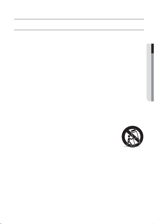
12. Use only with the cart, stand, tripod, bracket, or table specified by
the manufacturer, or sold with the apparatus. When a cart is used,
use caution when moving the cart/apparatus combination to avoid
injury from tip-over.
13. Unplug this apparatus during lighting storms or when unused for
long periods of time.
14. Refer all servicing to qualified service personnel. Servicing is required when the
apparatus has been damaged in any way, such as power-supply cord or plug is
damaged, liquid has been spilled or objects have fallen into the apparatus, the apparatus
has been exposed to rain or moisture, does not operate normally, or has been dropped.
● OVERVIEW
English _3
Page 4
overview
WARNING
TO REDUCE THE RISK OF FIRE OR ELECTRIC SHOCK, DO NOT EXPOSE
THIS PRODUCT TO RAIN OR MOISTURE. DO NOT INSERT ANY METALLIC
OBJECT THROUGH THE VENTILATION GRILLS OR OTHER OPENNINGS
ON THE EQUIPMENT.
Apparatus shall not be exposed to dripping or splashing and that no objects
filled with liquids, such as vases, shall be placed on the apparatus.
To prevent injury, this apparatus must be securely attached to the Wall/ceiling
in accordance with the installation instructions.
CAUTION
CAUTION
RISK OF ELECTRIC SHOCK.
DO NOT OPEN
CAUTION
REFER SERVICING TO QUALIFIED SERVICE PERSONNEL.
: TO REDUCE THE RISK OF ELECTRIC SHOCK.
DO NOT REMOVE COVER (OR BACK).
NO USER SERVICEABLE PARTS INSIDE.
EXPLANATION OF GRAPHICAL SYMBOLS
The lightning flash with arrowhead symbol, within an
equilateral triangle, is intended to alert the user to the
presence of “dangerous voltage” within the product’s
enclosure that may be of sufficient magnitude to constitute a
risk of electric shock to persons.
The exclamation point within an equilateral triangle is intended
to alert the user to the presence of important operating
and maintenance (servicing) instructions in the literature
accompanying the product.
4_ overview
Page 5

Class construction
An apparatus with CLASS construction shall be connected to a MAINS
socket outlet with a protective earthing connection.
Battery
Batteries(battery pack or batteries installed) shall not be exposed to excessive
heat such as sunshine, fire or the like.
Danger of explosion if battery is incorrectly replaced.
Replace only with the same or equivalent type.
Disconnection Device
Disconnect the main plug from the apparatus, if it’s defected. And please call
a repair man in your location.
When used outside of the U.S., it may be used HAR code with fittings of
an approved agency is employed.
CAUTION
These servicing instructions are for use by qualified service personnel only.
To reduce the risk of electric shock do not perform any servicing other than
that contained in the operating instructions unless you are qualified to do so.
The BNC Out terminal of the product is provided for easier installation, and is
not recommended for monitoring purposes.
If you keep the BNC cable connected, a risk of lightening may cause damage
or malfunction to the product.
Please use the input power with just one camera and other devices must not
be connected.
● OVERVIEW
English _5
Page 6

overview
Please read the following recommend safety precautions carefully.
Do not place this apparatus on an uneven surface.
Do not install on a surface where it is exposed to direct sunlight, near
heating equipment or heavy cold area.
Do not place this apparatus near conductive material.
Do not attempt to service this apparatus yourself.
Do not place a glass of water on the product.
Do not install near any magnetic sources.
Do not block any ventilation openings.
Do not place heavy items on the product.
User’s Manual is a guidance book for how to use the products.
The meaning of the symbols are shown below.
Reference : In case of providing information for helping of product’s usages
Notice : If there’s any possibility to occur any damages for the goods and
human caused by not following the instruction
Please read this manual for the safety before using of goods and keep it in
the safe place.
6_ overview
Page 7

CONTENTS
OVERVIEW
3
INSTALLATION &
CONNECTION
28
NETWORK CONNECTION
AND SETUP
50
3 Important Safety Instructions
9 Product Features
10 Recomended PC Specifications
10 Recomended SD/SDHC Memory
Card Specifications
11 What’s Included
14 At a Glance (SNB-7002)
At a Glance (SND-7082)
18
22 At a Glance (SND-7082F)
25 At a Glance (SNV-7082)
28 Mounting the Lens (SNB-7002)
30 Installation (SND-7082)
32 Installation (SND-7082F)
34 Installation (SNV-7082)
39
Inserting/Removing a SD Memory Card
43 Memory Card Information
(Not Included)
44 Connecting with other Device
50 Connecting the Camera Directly
to Local Area Networking
51 Connecting the Camera Directly
to a DHCP Based DSL/Cable
Modem
52 Connecting the Camera Directly
to a PPPoE Modem
53 Connecting the Camera to a
Broadband Router with the
PPPoE/Cable Modem
54 Buttons used in IP Installer
55 Static IP Setup
59 Dynamic IP Setup
60 Port Range Forward (Port
Mapping) Setup
62 Connecting to the Camera from
a Shared Local PC
62 Connecting to the Camera from
a Remote PC via the Internet
● OVERVIEW
English _7
Page 8

overview
WEB VIEWER
63
SETUP SCREEN
75
APPENDIX
123
63 Connecting to the Camera
64 Login
65 Installing Silverlight Runtime
69 Installing STW WebViewer Plugin
70 Using the Live Screen
72 Search and play by event
73 Search and play by time
75 Setup
75 Video & Audio Setup
91 Network Setup
100 Event Setup
116 System Setup
123 Specification
129 Product Overview
133 Troubleshooting
135 Open Source Announcement
8_ overview
Page 9

PRODUCT FEATURES
• Full HD Video Quality
Multi-Streaming
•
This network camera can display videos in different resolutions and qualities
simultaneously using different CODECs.
• Web Browser-based Monitoring
Using the Internet web browser to display the image in a local network environment.
• Alarm
If an event occurs, the event-related video will be transferred to the FTP/email specified
by the user or saved to the SD memory
port.
• Tampering Detection
Detects tempering attempts on video monitoring.
• Motion Detection
Detects motion from the camera’s video input.
• Intelligent Video Analysis
Analyzes video to detect logical events of specified conditions from the camera’s video
input.
• Face Detection
Detects faces from the camera’s video input.
• Smart Codec
Adaptively applies codecs for a portion of the camera’s field of view to improve the quality
of such area specified by user.
• Audio Detection
Detects sound louder than a certain level specified by user.
Auto Detection of Disconnected Network
•
Detects network disconnection before triggering an event.
• ONVIF Compliance
This product supports ONVIF.
For more information, refer to www.onvif.org.
, or the event signal will be sent to the Alarm Out
● OVERVIEW
English _9
Page 10

overview
RECOMENDED PC SPECIFICATIONS
• CPU : Intel Core 2 Duo 2.4GHz or higher
• Operating System : Windows XP
• Resolution : 1280X1024 pixels or higher (32 bit color)
• RAM : 2GB or higher
eb Browser : Internet Explorer 7 or Higher, Firefox 9 or Higher, Chrome 15 or Higher,
• W
Neither a beta test version unlike the version released in the company website nor the developer version will
be supported.
It is recommended to connect to IPv6 in Windows 7.
• Video Memory : 256MB or higher
Safari 5.1 or Higher
If the driver of the video graphic adapter is not installed properly or is not the latest version, the
J
video may not be played properly.
For a multi-monitoring system involving at least 2 monitors, the playback performance can be
deteriorated depending on the system.
RECOMENDED SD/SDHC MEMORY CARD SPECIFICATIONS
• 4GB ~ 32GB
ecommended to use memory cards of at least class 6 speed.
• It is r
, VISTA, 7, Mac OS
10_ overview
Page 11
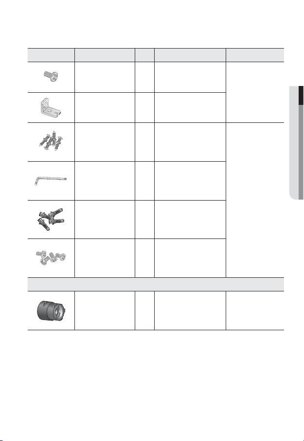
WHAT’S INCLUDED
UNLOCK
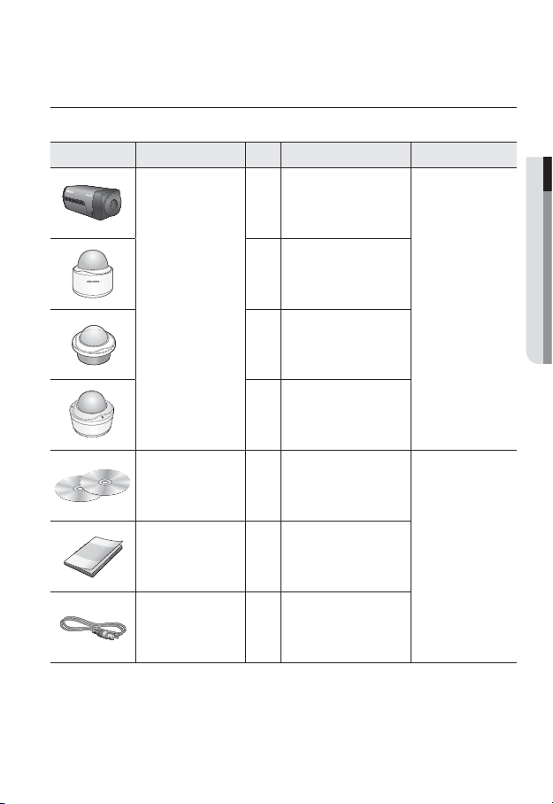
Please check if your camera and accessories are all included in the product package.
Appearance Item Name
Quantity
1
Description Model Name
● OVERVIEW
1
Camera
1
SNB-7002 or
SND-7082 or
SND-7082F or
SNV-7082
1
Instruction book,
Installer S/W CD,
2
CMS S/W DVD
SNB-7002/
Quick Guide
(Optional)
1
SND-7082/
SND-7082F/
SNV-7082
Cable for the testing
monitor
Used to test the camera
1
connection to a portable display
device
English _11
Page 12
overview
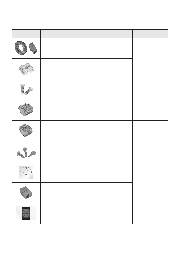
Appearance Item Name
C Mount Adapter,
Auto Iris Lens Connector
Camera Holder (Mount) 1
Camera Holder (Mount)
Screws
6-position Terminal Block
5-position Terminal Block
Iron Screw 3 Used for fixing to an iron plate
Template
Jack Modular 1 LAN cable gender
Quantity
1
2 Used to install the mount
1
1
1
Description Model Name
Used to install the C Mount
camera lens
Used to install the camera
holder
Used for alarm in/out terminals
Used for alarm in/out terminals
Product installation guide
SNB-7002
SND-7082/
SND-7082F/
SNV-7082
SND-7082/
SND-7082F
SND-7082F/
SNV-7082
12_ overview
Dustproof Plate 1
Prevents dust ingress into the
wiring connection part.
SND-7082
Page 13
Appearance Item Name
Tapping Screw 1 Used to fix the safety bracket
Bracket Safety 1 Safety Bracket
Quantity
Description Model Name
SND-7082F
● OVERVIEW
ASSY-Tapping Screw
L Wrench
Plastic Anchor
Machine Screws 4
Lens Options (not included)
CS/C Lens
Used for installation on the wall
4
1
or ceiling
Used to remove/
fix the dome cover
For fixing a screw,
4
Inserted in a hole
(reinforced anchoring force)
Used for assembling the dome
case when installing the product
on the pipe, wall mount, etc. or
blocking a hole.
Optional lens to be inserted in
a camera
SNV-7082
SNB-7002
English _13
Page 14
overview
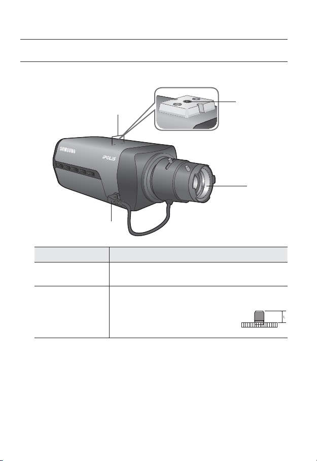
AT A GLANCE (SNB-7002)
Front Side
Item Description
Camera Holder
(Mount) Holes
Mounting Bracket
b
Screw Hole
Used when you mount the camera onto the bracket by fixing the camera
holder (mount) adaptor with the bracket.
Used to fix the camera on a bracket or mounting bracket.
The screw size : use this screw to fix the mounting bracket.
1/4" - 20UNC (20THREAD)
L : 4.5mm±0.2mm (ISO Standard) or 0.197" (ASA
Standard)
b
<Fixed Bracket>
c
14_ overview
Page 15

Item Description
Auto Iris Lens
c
(Optional)
Auto Iris Lens
Connector
Wipe out a dirty surface of the lens softly with a lens tissue or cloth to which you have applied
M
ethanol.
Mounting Bracket is not included.
For more information to use mounting bracket, refer to the product’s documentation.
Installed on the lens adaptor.
Used to supply power and output signal to control the iris of the lens.
● OVERVIEW
English _15
Page 16
overview
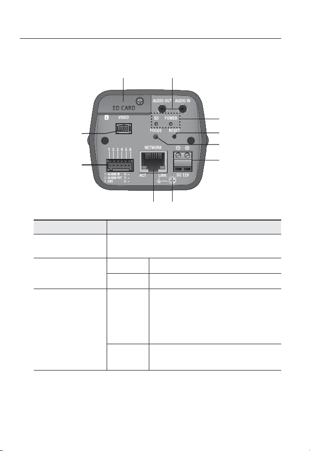
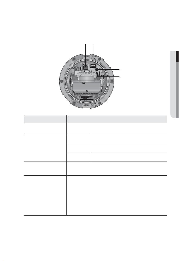
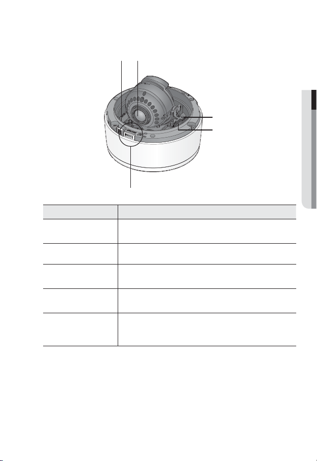
Rear Side
Item Description
SD Memory Card
Compartment
Audio terminal
b
SD, Power Indicators
c
b
c
Compartment for the SD memory card.
AUDIO OUT Used to connect to speakers.
AUDIO IN Used to connect to a microphone.
ON : A memory card is inserted and operates normally.
Flashing :
SD
POWER
Failed to record, insufficient space, or inserted
abnormally.
OFF : Camera is off, camera is restarting, memory card is
not in place, or when record is off.
ON : While the power is on
OFF : If the power is off
16_ overview
Page 17

Item Description
The button restores all camera settings to the factory default.
Press and hold for about 5 seconds to reboot the system.
If you reset the camera, the network settings will be adjusted so that
Reset Button
Focus Adjustment
Button
Power Port Used to plug the power cable.
Lightning protective
grounding port
Network Port Used to connect the PoE or Ethernet cable for network connection.
Alarm I/O Port
Test Monitor Out
J
DHCP can be enabled. If there is no DHCP server in the network, you
must run the IP Installer program to change the basic network settings
such as IP address, Subnet mask, Gateway, etc., before you can connect
to the network.
The button adjusts the focus of image automatically.
Used to discharge the lightning current safely outside in order to protect the
camera.
ALARM IN Used to connect the alarm input signal.
ALARM OUT
GND Used for earth-grounding.
Output port for test monitoring the video output. Use the test monitor cable
to connect to a mobile display and check the test video.
Used to connect the alarm output signal.
● OVERVIEW
English _17
Page 18
overview
UNLOCK
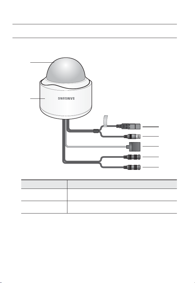
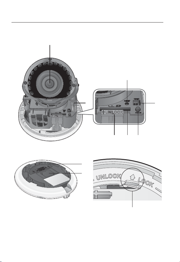
AT A GLANCE (SND-7082)
Appearance
b
Item Description
Top cover
Case cover used to protect the lens and the main unit.
c
Camera Case
b
18_ overview
Housing part that covers the camera body.
Page 19
Item Description
c
Power Port
Test Monitor Out
Used to plug the power cable.
Output port for test monitoring the video output. Use the test monitor cable
to connect to a mobile display and check the test video.
● OVERVIEW
Network Port
Audio In Jack
Audio Out Jack
Used to connect the PoE or Ethernet cable for network connection.
Used to connect to a microphone.
Used to connect to speakers.
English _19
Page 20
overview
UNLOCK
Components
c
20_ overview
UNLOCK
b
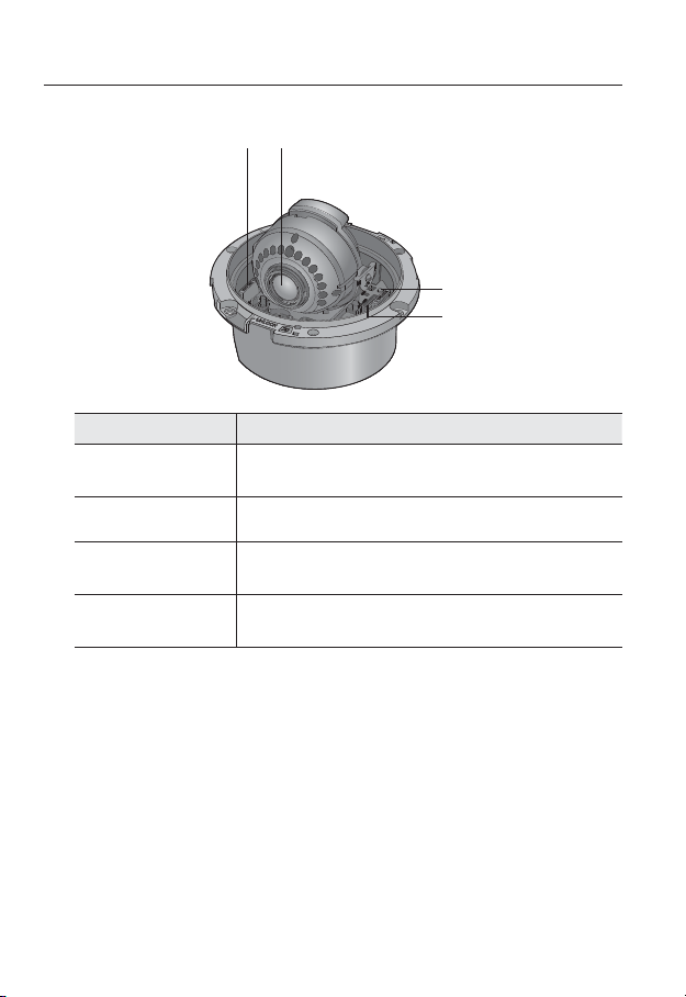
Page 21
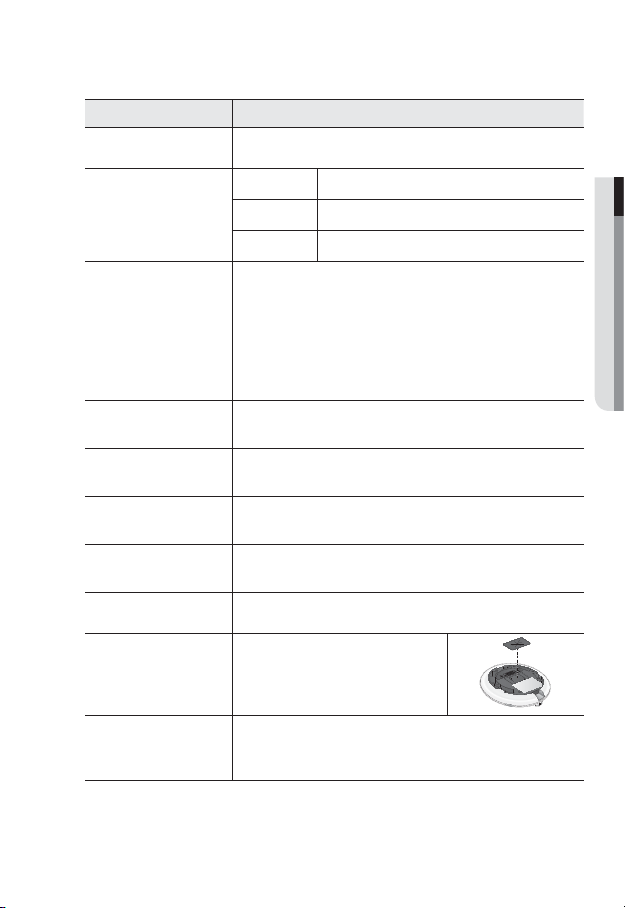
Item Description
Lens Lens for the camera.
ALARM IN Used to connect the alarm input signal.
Alarm I/O Port
b
Reset Button
c
Test Monitor Out
Focus Adjustment
Button
SD Memory Card
Compartment
Lock Release Lever
Bracket Used to install the camera on the wall or ceiling with the screws.
Wiring Cover
Release Lock
ALARM OUT Used to connect the alarm output signal.
GND Used for earth-grounding.
The button restores all camera settings to the factory default.
Press and hold for about 5 seconds to reboot the system.
If you reset the camera, the network settings will be adjusted so that
J
DHCP can be enabled. If there is no DHCP server in the network, you
must run the IP Installer program to change the basic network settings
such as IP address, Subnet mask, Gateway, etc., before you can
connect to the network.
Output port for test monitoring the video output. Use the test monitor cable
to connect to a mobile display and check the test video.
The button adjusts the focus of image automatically.
Compartment for the SD memory card.
Press the <UNLOCK> levers on both ends to separate camera module from
the body.
If you drill a hole in the wiring cover for wiring,
remove the cover and attach the provided
dustproof plate to it, and arrange the cables
through the plate.
If you want to remove the bracket from the main unit or remove the camera
from the bracket, push this out and turn the main unit in the <UNLOCK>
direction.
● OVERVIEW
English _21
Page 22
overview
AT A GLANCE (SND-7082F)
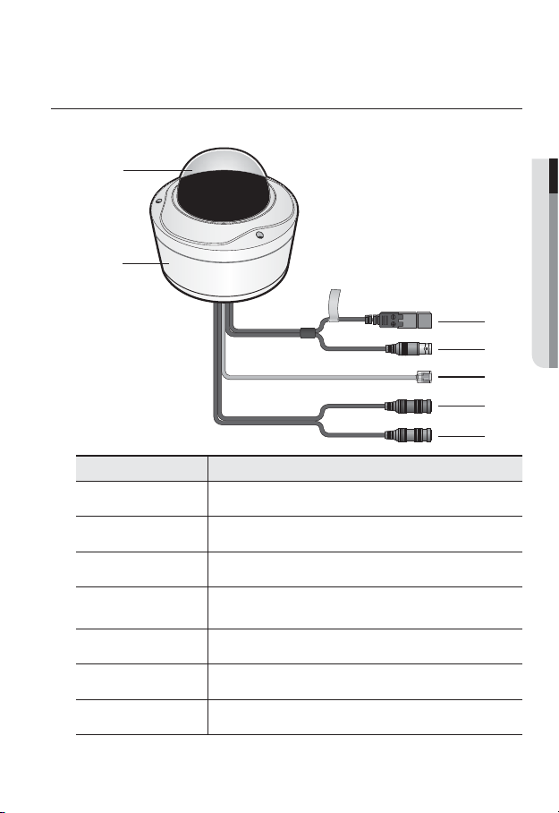
Appearance
b
Item Description
Top cover
Case cover used to protect the lens and the main unit.
c
Camera Case
b
Power Port
c
Test Monitor Out
Network Port
Audio In Jack
Audio Out Jack
22_ overview
Housing part that covers the camera body.
Used to plug the power cable.
Output port for test monitoring the video output. Use the test monitor cable
to connect to a mobile display and check the test video.
Used to connect the PoE or Ethernet cable for network connection.
Used to connect to a microphone.
Used to connect to speakers.
Page 23
Components
b
c
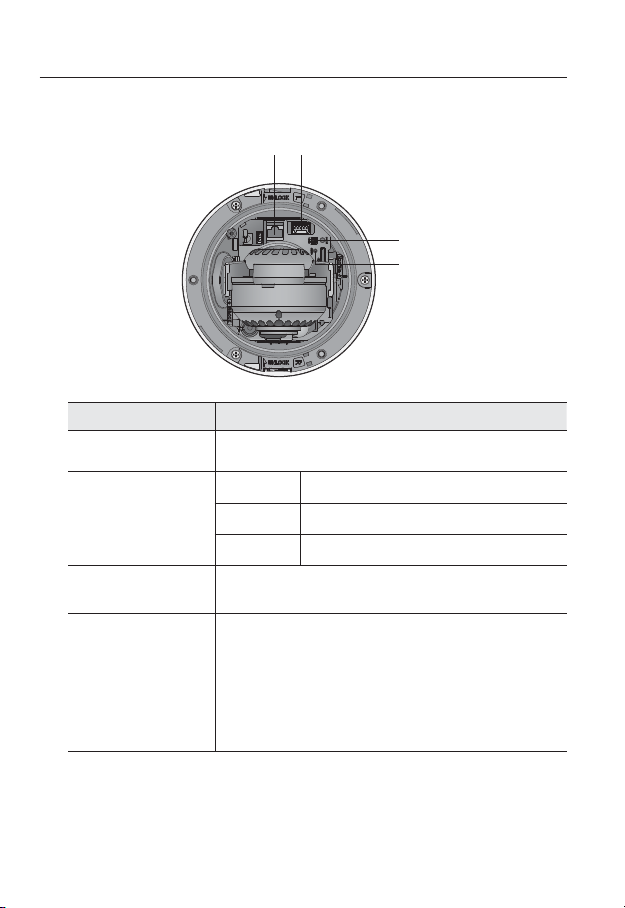
Item Description
Network Port Used to connect the PoE or Ethernet cable for network connection.
ALARM IN Used to connect the alarm input signal.
b
c
Alarm I/O Port
Test Monitor Out
Reset Button
ALARM OUT
GND Used for earth-grounding.
Output port for test monitoring the video output. Use the test monitor cable
to connect to a mobile display and check the test video.
The button restores all camera settings to the factory default.
Press and hold for about 5 seconds to reboot the system.
If you reset the camera, the network settings will be adjusted so that
J
DHCP can be enabled. If there is no DHCP server in the network, you
must run the IP Installer program to change the basic network settings
such as IP address, Subnet mask, Gateway, etc., before you can
connect to the network.
Used to connect the alarm output signal.
● OVERVIEW
English _23
Page 24
overview
Item Description
Lock Release Lever
Lens Lens for the camera.
Focus Adjustment
Button
SD Memory Card
Compartment
Press the <UNLOCK> levers on both ends to separate camera module from
the body.
The button adjusts the focus of image automatically.
Compartment for the SD memory card.
24_ overview
Page 25
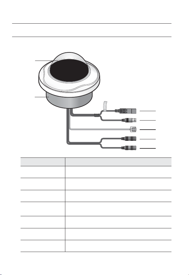
AT A GLANCE (SNV-7082)
Appearance
b
Item Description
Top cover
Case cover used to protect the lens and the main unit.
● OVERVIEW
c
b
c
Camera Case
Power Port
Test Monitor Out
Network Port
Audio In Jack
Audio Out Jack
Housing part that covers the camera body.
Used to plug the power cable.
Output port for test monitoring the video output. Use the test monitor cable
to connect to a mobile display and check the test video.
Used to connect the PoE or Ethernet cable for network connection.
Used to connect to a microphone.
Used to connect to speakers.
English _25
Page 26
overview
Components
Item Description
Network Port Used to connect the PoE or Ethernet cable for network connection.
Alarm I/O Port
b
Test Monitor Out
c
Reset Button
b
c
ALARM IN Used to connect the alarm input signal.
ALARM OUT
GND Used for earth-grounding.
Output port for test monitoring the video output. Use the test monitor cable
to connect to a mobile display and check the test video.
The button restores all camera settings to the factory default.
Press and hold for about 5 seconds to reboot the system.
If you reset the camera, the network settings will be adjusted so that
J
DHCP can be enabled. If there is no DHCP server in the network, you
must run the IP Installer program to change the basic network settings
such as IP address, Subnet mask, Gateway, etc., before you can
connect to the network.
Used to connect the alarm output signal.
26_ overview
Page 27
Item Description
Lock Release Lever
Lens Lens for the camera.
Focus Adjustment
Button
SD Memory Card
Compartment
Release Lock
Press the <UNLOCK> levers on both ends to separate camera module from
the body.
The button adjusts the focus of image automatically.
Compartment for the SD memory card.
If you want to remove the bracket from the main unit or remove the camera
from the bracket, push this out and turn the main unit in the <UNLOCK>
direction.
● OVERVIEW
English _27
Page 28
installation & connection
MOUNTING THE LENS (SNB-7002)
Disconnect the power before proceeding.
The C lens and CS lens are not included in the product package.
M
It is recommended that megapixel lens are use on this camera to optimise performance.
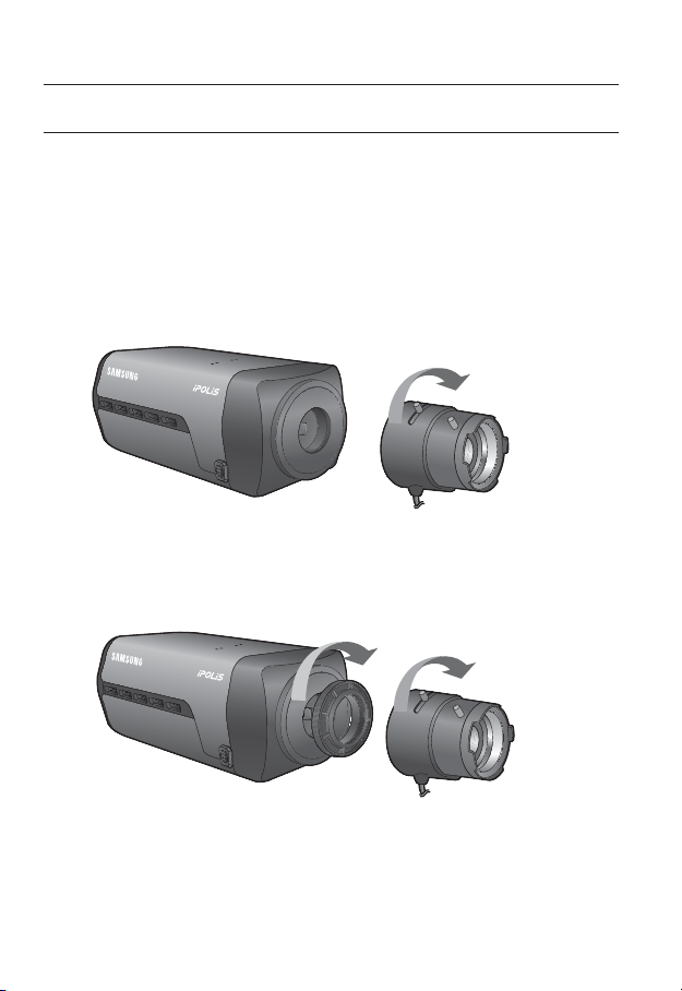
Mounting the CS lens on a camera
Turn the optional CS lens clockwise to insert it.
Mounting the C lens on a camera
Turn the C mount adaptor clockwise to insert it and do the same with the C lens.
CS Lens
28_ installation & connection
C Lens
Page 29
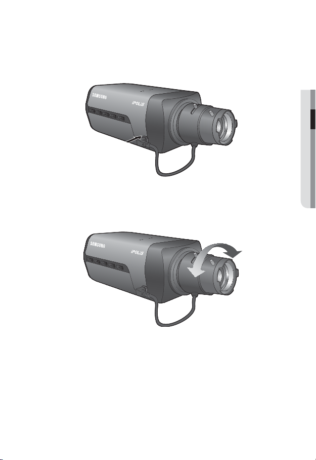
Connecting the Auto Iris Lens connector
Insert the lens connector into the corresponding hole of the camera.
● INSTALLATION & CONNECTION
Focusing
Turn the lens left or right to control the zoom and focus the lens so that you can view a clear,
sharp object.
English _29
Page 30
installation & connection
Precautions before installation
Ensure you read out the following instructions before installing the camera:
• When installing on a ceiling or wall, desir
times of the camera’s weight.
• Stuck-in or peeled-off cables can cause damage to the product or a fire.
• For safety purposes, keep anyone else away from the installation site.
And put aside personal belongings from the site, just in case.
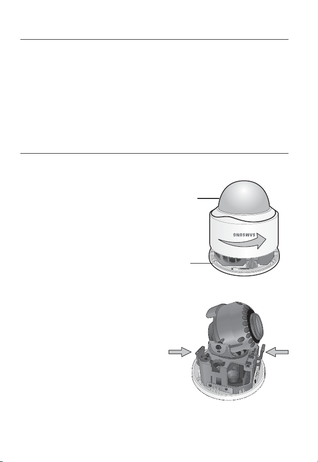
INSTALLATION (SND-7082)
Disassembling
1. Take the camera body with one hand
and take the top cover with the other
hand. Then, turn the cover counter
clockwise to remove it.
ess the <UNLOCK> levers on both ends
2. Pr
to separate camera module from the body.
ed spot must be capable of supporting at least 5
Top cover
Camera Body
UNLOCK
30_ installation & connection
Page 31

3.
Hold down the lock lever in the outer direction as shown
Camera Body
and turn the camera body in the <UNLOCK> direction
(counter clockwise) to remove the bracket from the
body.
If it fails, take the bottom hole of the bracket and turn the
bracket in the <LOCK> direction (clockwise) to remove it.
Bracket
Installation
1. Use the provided screws (x3) to fix the
bracket to a desired position on the ceiling or
wall.
Ensure that the <CAMERA FRONT> label on the
bracket faces the direction for camera monitoring.
2. Arrange the cables thr
the ceiling or wall.
If you drill a hole in the ceiling cover for wiring, press
hard to remove the cover and attach the dust-proof
plate to it, and arrange the cables through the plate.
If you intend to arrange the cables without drilling a
hole, use the empty area opposite to the <CAMERA
FRONT> label side for the wiring purpose.
3.
Mount the camera body onto the bracket.
Align the marking hole of the camera body with the <CAMERA FRONT> label of the
bracket, and turn the body in the <LOCK> direction.
4.
Assemble the camera module to the body.
5.
Refer to “Adjusting the monitoring direction
for the camera” to adjust the lens in a desired
direction. (page 38)
6. Close the top cover.
Fit the top cover into the fixing tips of the camera
body and turn the cover clockwise.
ough the bracket to
Wiring Cover
UNLOCK
● INSTALLATION & CONNECTION
English _31
Page 32

installation & connection
INSTALLATION (SND-7082F)
Disassembling
1. Take the camera body with one
hand and take the top cover
with the other hand. Then, turn
the cover counter clockwise to
remove it.
Camera Body
Installation
1. Use the provided template to drill one hole for
the camera, and one for the screw (5 mm in
diameter, at least 35 mm in depth), and insert
the plastic anchor (HUR 5) to the end of the
screw hole.
2. Connect and arrange the necessary cables
lest that they should be damaged or twisted
while installing the camera.
3. Insert the camera body into the hole so that it
fits to the camera hole, and fix the body using
the ASSY tapping screws (TH M4xL30). (x3)
4. Refer to “Adjusting the monitoring direction for the camera” to adjust the lens in
ed direction. (page 38)
a desir
5. Close the top cover
Fit the top cover into the fixing tips of the camera body and turn the cover clockwise.
.
Top cover
32_ installation & connection
Page 33

To add an alarm cable (not included)
1. For this, first you should remove the top cover
from the housing.
2. Pull out the protruding rubber bar as shown.
3. This will reveal a hole in the place of the rubber
bar, through which you insert the cable, and
connect it to the alarm terminal on the PCB.
4. Connect and arrange the necessary cables
(power, video, etc) lest that they should be
damaged or caught while installing the camera.
Then, install the camera assembly in the reverse
order of the disassembly.
5. Refer to “Adjusting the monitoring direction
for the camera” to adjust the lens in a desired
(page 38)
direction.
6. Close the top cover.
● INSTALLATION & CONNECTION
English _33
Page 34

installation & connection
INSTALLATION (SNV-7082)
Disassembling
1. With the provided L-shaped
wrench, loosen 3 bolts on the
top cover counter clockwise to
remove the cover.
2. Loosen 3 screws on the camera
body counter clockwise, and
push down the left/right LOCKER
lever (in the arr
release the lock. Then, remove
the camera from the case.
ow direction) to
Bolts
Camera Body
LOCKER Lever
Top cover
Camera Case
34_ installation & connection
Page 35

Installing on the ceiling directly
1. Remove the top cover from the case by referring to the “Disassembling” section.
(page 34)
2. Drill a hole (diameter: 5mm, depth: min 35mm) in a
ed position of the case bottom and insert the
desir
provided plastic anchor (HUD 5) to the end.
3. Fit the bottom hole to the anchor hole and insert
and fix the ASSY taping screw (TH M4×L30).
When assembling the camera case to a junction box, select
appropriate screw holes on the case bottom for installation.
4. Connect and arrange the necessary cables lest that
they should be damaged or twisted while installing
the camera.
5. Install the camera body in the r
“Disassembling”. (page 34)
6. Adjust the lens in a desir
direction for the camera" section. (page 38)
7. Close the top cover
To ensure waterproofing, tight up the fixing bolts using the L-wrench.
.
everse order of
ed direction by referring to the “Adjusting the monitoring
CAMERA FRONT
Ceiling mount
1. Remove the top cover from the case by
referring to the “Disassembling” section.
(page 34)
2. Use the provided template to drill one hole for
the camera, and one for the screw (5 mm in
diameter, at least 35 mm in depth), and insert
the plastic anchor (HUR 5) to the end of the
screw hole.
3. Connect and arrange the necessary cables
lest that they should be damaged or twisted
while installing the camera.
● INSTALLATION & CONNECTION
English _35
Page 36

installation & connection
4. Loosen and remove the case-fixing screws on the camera unit. (x3)
5. Insert the camera unit into the hole so that it fits to the camera hole, and fix the unit
using the ASSY tapping screws (TH M4×L30). (x3)
6. Adjust the lens in a desired direction by referring to the “Adjusting the monitoring
direction for the camera” section. (page 38)
7. Close the top cover
To ensure waterproofing, tight up the fixing bolts using the L-wrench.
Attaching to the unbundled adapter
Choose and purchase a necessary one of the following options (unbundled) that is suitable
to the installation site or for your convenience.
1. Remove the top cover from the case by referring to
the “Disassembling” section. (page 34)
2. Use the pr
case to the unbundled adapter.
3. Connect and arrange the necessary cables lest that
they should be damaged or twisted while installing
the camera.
4. Install the camera body in the reverse order of
“Disassembling”. (page 34)
5. Adjust the lens in a desir
the “Adjusting the monitoring direction for the
camera” section. (page 38)
6. Close the top cover
To ensure waterproofing, tight up the fixing bolts using the L-wrench.
Optional Accessories for Installation
For your easier installation, you can purchase appropriate optional accessories available.
1. WALL MOUNT ADAPTOR(SBP-300WM or
SBP-300WM1)/HANGING MOUNT
(SBP-300HM3)
This adaptor is used when installing the
dome camera onto a wall.
.
ovided machine screw to fix the camera
ed direction by referring to
.
36_ installation & connection
Page 37

2. CEILING MOUNT ADAPTOR(SBP-300CM)/
HANGING MOUNT(SBP-300HM3)
This adaptor is used when installing the dome
camera on a concrete ceiling.
3. POLE MOUNT ADAPTOR(SBP-300PM)
This is an adaptor for WALL MOUNT ADAPTOR
(SBP-300WM or SBP-300WM1) installation on a
pole whose diameter is bigger than 80mm.
4. CORNER MOUNT ADAPTOR (SBP-300KM)
This is an adaptor for WALL MOUNT
ADAPTOR (SBP-300WM or SBP-300WM1)
installation on the corner of wall joint.
● INSTALLATION & CONNECTION
English _37
Page 38

installation & connection
Adjusting the monitoring direction for the camera (SND-7082/
SND-7082F/SNV-7082)
Pan
Tilt
Cover front
Tilt cramp screw
Lens rotation
Adjusting the monitoring direction
You can adjust the camera direction only when the camera is fixed on the ceiling.
Where, rotating the camera unit to the left or right is called Pan, adjusting the tilt is called
Tilt, and turning the lens on its axis is called Rotation.
- The effective range of pan is a total of 355 degrees.
- The effective range of rotation is a total of 355 degrees.
- The effective range of tilt is a total of 90 degrees.
In some angles, the top cover may cause cutting some part of the monitoring object.
J
Do not rotate the focus/zoom lens by force after removing the cover front.
Otherwise, it may cause an incorrect focus due to a motor failure.
Methods of adjustment
1. After installing the camera, adjust the panning angle in consideration of the
monitoring direction.
When tilting the camera, you should adjust the horizontal angle lest that the image
be displayed reversely.
2. Adjust the rotation angle to correct the image display position (up/down/left/right).
Rotation means rotation on the basis of the rear lens unit.
Adjust the tilt angle so that the camera faces toward the monitoring object.
3.
38_ installation & connection
Page 39

INSERTING/REMOVING A SD MEMORY CARD
Disconnect the power cable from the camera before inserting the SD memory card.
J
Inserting a SD Memory Card
Loosen the screw and open the cover of the SD memory card. Insert the SD card in the
arrow direction as shown.
<SNB-7002>
Push the SD memory card in the direction of the arrow shown in the diagram.
UNLOCK
● INSTALLATION & CONNECTION
<SND-7082>
English _39
Page 40

installation & connection
<SND-7082F>
<SNV-7082>
Do not insert the SD memory card while it’s upside down by force. Otherwise, it may damage the
J
SD memory card.
40_ installation & connection
Page 41

Removing a SD Memory Card
Gently press down on the exposed end of the memory card as shown in the diagram to
eject the memory card from the slot.
<SNB-7002>
UNLOCK
<SND-7082>
● INSTALLATION & CONNECTION
English _41
Page 42

installation & connection
<SND-7082F>
<SNV-7082>
Pressing too hard on the SD memory card can cause the card to shoot out uncontrollably from the
J
slot when released.
To remove the SD memory card, set the card to <Off> in <Storage> menu and press
[Apply (
Removing the SD memory card while it’s in use for saving may damage the data stored in the
card.
42_ installation & connection
)] button. (Page 102)
Page 43

MEMORY CARD INFORMATION (NOT INCLUDED)
What is a memory card?
The memory card is an external data storage device that has been developed to offer an
entirely new way to record and share video, audio, and text data using digital devices.
Selecting a memory card that’s suitable for you
Your camera supports SD/SDHC memory cards.
You may, however, experience compatibility issues depending on the model and make of
the memory card.
For your camera, we recommend you use a memory card from the following
manufacturers:
SD/SDHC Memory Card : Sandisk, Transcend
Memory cards of 4GB ~ 32GB is recommended for using with this camera.
Playback performance can be affected depending on the speed of memory card, so use
the high-speed memory card.
It is recommended to use memory cards of at least class 6 speed.
Memory Card Use
SD and SDHC memory cards feature a switch that disables writing data on to the media.
Having this switch to the Lock position will prevent accidental deletion of data stored in the
memory card but at the same time will also prevent you from writing data on to the media.
Memory Card Components
Contacts
Lock Switch
● INSTALLATION & CONNECTION
SD/SDHC
English _43
Page 44

installation & connection
UNLOCKUNLOCK
CONNECTING WITH OTHER DEVICE
Monitor to install
Power
Grounding cable
Ethernet
Power
The BNC Out terminal of the product is provided for easier installation, and is not recommended
J
for monitoring purposes. If you keep the BNC cable connected, a risk of lightening may cause
damage or malfunction to the product.
44_ installation & connection
Ethernet
Monitor to install
Page 45

Ethernet Connection
Connect the Ethernet cable to the local network or to the Internet.
Power Supply
Use the screwdriver to connect each line (+, –) of the power cable to the corresponding
power port of the camera.
If both PoE (Power over Ethernet) and DC 12V are supplied, the product will operate with the first-
J
applied power source.
- You can also use a router featuring PoE to supply power to the camera.
- Use PoE that is compliant with the IEEE802.3af protocols.
- It is advisable to use only one power source from PoE and DC12V.
The heater will operate properly only by the power source of PoE. (SNV-7082)
- If using DC 12V, the heater will not operate at all.
- Use PoE in a low-temperature place of less than -10°C.
Be careful not to reverse the polarity when you connect the power cable.
If you want to connect an external device, you must turn off the external device before proceeding.
Electrical Resistance of Copper Wire at [20°C (68°F)]
Copper Wire Gauge (AWG) #24(0.22mm2) #22(0.33mm2) #20(0.52mm2) #18(0.83mm2)
Resistance (Ω/m) 0.078 0.050 0.030 0.018
Drop Voltage (V/m) 0.028 0.018 0.011 0.006
Recommended Distance (m) Less than 20 Less than 30 Less than 30 Less than 30
As shown in the table above, you may encounter a voltage-sag depending on the wire length.
If you use an excessively long wire for camera connection, the camera may not work properly.
Camera Operating Voltage : DC 12V±10%
-
Voltage drop measurements on the chart above may vary depending on the type and manufacture of
-
the copper cable.
● INSTALLATION & CONNECTION
English _45
Page 46

installation & connection
Grounding the Product (SNB-7002)
Use a screw driver to connect earth grounding cable to the ground terminal below the
power inlet terminal.
Grounding protects the product from a surge or lightning.
J
When grounding, make sure to turn the product’s power off.
Recommended Grounding Cable
• Length : Less than 3M
• Gauge : 18 AWG or bigger
Ex) UL1007 AWG 18/16, UL1015 AWG18/16/14/12, UL2468 AWG18/16/14
46_ installation & connection
Page 47

Connecting to Audio Input/Output
UNLOCK
Speaker
Microphone
Microphone
Microphone
Speaker Amp
Amp
Amp
Speaker
Microphone
Microphone
Network
PC
● INSTALLATION & CONNECTION
Speaker
Amp
Speaker
English _47
Page 48

installation & connection
1. Connect the AUDIO IN port of the camera with the microphone or LINE OUT port of
the amplifier that the microphone is connected to.
2. Connect the AUDIO OUT port of the camera with the speaker or LINE IN port of the
amplifier that the speaker is connected to.
3. Check the specifications for audio input.
• Audio Codec
G.711 PCM. μ-law 64kbps 8kHz / G.726 (16Kbps, 24Kbps, 32Kbps, 40Kbps)
sampling
• Full duplex Audio
• Audio in
Used for mono signal line input (Max.2.4 Vpp)
• Audio out
Used for mono signal line output (Max.2.4 Vpp)
• Line out impedance
600
Connecting to the I/O port box (SNB-7002)
Connect the Alarm I/O signal to the corresponding port of the rear port box.
• ALARM IN : Used to connect the alarm input signal.
• ALARM OUT : Used to connect the alarm output signal.
• GND : Used for earth-grounding.
48_ installation & connection
Page 49

Connecting to the I/O port box (SND-7082/SND-7082F/SNV-7082)
Connect the Alarm I/O cable to the corresponding port of the inner port box.
1 : ALARM IN 4 : 2 : ALARM OUT 5 : 3 : GND
UNLOCK
• ALARM IN : Used to connect the alarm input signal.
• ALARM OUT : Used to connect the alarm output signal.
• GND : Used for earth-grounding.
To connect the external sensor
Connect one strand of each signal line (2-strand) of the sensors to the [ALARM IN] port,
and connect the other strand to the [GND] port.
Alarm I/O Wiring Diagram
● INSTALLATION & CONNECTION
English _49
Page 50

network connection and setup
UNLOCK
UNLOCK
You can set up the network settings according to your network configurations.
CONNECTING THE CAMERA DIRECTLY TO LOCAL AREA
NETWORKING
Connecting to the camera from a local PC in the LAN
1. Launch an Internet browser on the local PC.
2. Enter the IP address of the camera in the address bar of the browser.
Camera
INTERNET
Camera
Local PC
<Local Network>
A remote PC in an external Internet out of the LAN network may not be able to connect to the
M
camera installed in the intranet if the port-forwarding is not properly set or a firewall is set.
In this case, to resolve the problem, contact your network administrator.
By factory default, the IP address will be assigned from the DHCP server automatically. If there is
no DHCP server available, the IP address will be set to 192.168.1.100.
To change the IP address, use the IP Installer.
For further details on IP Installer use, refer to “Static IP Setup”. (Page 55)
50_ network connection and setup
Firewall
External Remote PC
DDNS Server
(Data Center, KOREA)
Page 51

CONNECTING THE CAMERA DIRECTLY TO A DHCP
UNLOCK
BASED DSL/CABLE MODEM
DSL/Cable Modem
Camera
INTERNET
DDNS Server
(Data Center, KOREA)
External Remote PC
1. Use the cross LAN cable to connect the network cable directly to your PC.
2. Run the IP Installer and change the IP address of the camera so that you can use
the web browser on your desktop to connect to the Internet.
3. Use the Inter
net browser to connect to the web viewer.
4. Move to [Setup] page.
5. Move to [Network] – [DDNS] and configure the DDNS settings.
6. Move to [Network] – [Interface], and set the network type to [DHCP].
7. Connect the camera, which was removed from your PC, directly to the modem.
8. Restart the camera.
For registering the DDNS settings, refer to “Registering with DDNS”. (page 94)
M
For configuring the DDNS settings, refer to “DDNS”. (page 93)
For setting the network type, refer to “Interface”. (page 91)
●
NETWORK CONNECTION AND SETUP
English _51
Page 52

network connection and setup
UNLOCK
CONNECTING THE CAMERA DIRECTLY TO A PPPoE
MODEM
PPPoE Modem
Camera
1. Use the cross LAN cable to connect the network cable directly to your PC.
2. Run the IP Installer and change the IP address of the camera so that you can use
the web browser on your desktop to connect to the Internet.
3. Use the Inter
4. Move to [Setup] page.
5. Move to [Network] – [DDNS] and configure the DDNS settings.
6. Move to [Network] – [Interface], and set the network type to [PPPoE].
7. Connect the camera, which was removed from your PC, directly to the modem.
8. Restart the camera.
M
net browser to connect to the web viewer.
For registering the DDNS settings, refer to “Registering with DDNS”. (page 94)
For configuring the DDNS settings, refer to “DDNS”. (page 93)
For setting the network type, refer to “Interface”. (page 91)
INTERNET
DDNS Server
(Data Center, KOREA)
External Remote PC
52_ network connection and setup
Page 53

CONNECTING THE CAMERA TO A BROADBAND ROUTER
UNLOCK
UNLOCK
WITH THE PPPoE/CABLE MODEM
This is for a small network environment such as homes, SOHO and ordinary shops.
Camera
PPPoE or
Broadband
Cable Modem
Camera
Local PC
Router
Configuring the network settings of the local PC connected to a
Broadband Router
Configuring the network settings of the local PC connected to a Broadband Router, follow
the instructions below.
• Select : <Network Neighborhood> <Properties> <Local Area Connection>
<Properties> <General> <Internet Protocol (TCP/IP)> <Properties>
<Obtain an IP address automatically> or <Use the following IP address>.
• Follow the instructions below if you select <Use the following IP address>:
ex1) If the address (LAN IP) of the Broadband Router is 192.168.1.1
IP address : 192.168.1.100
Subnet Mask : 255.255.255.0
Default Gateway : 192.168.1.1
ex2) If the address (LAN IP) of the Broadband Router is 192.168.0.1
IP address : 192.168.0.100
Subnet Mask : 255.255.255.0
Default Gateway : 192.168.0.1
ex3) If the address (LAN IP) of the Broadband Router is 192.168.xxx.1
IP address : 192.168.xxx.100
Subnet Mask : 255.255.255.0
Default Gateway : 192.168.xxx.1
For the address of the Broadband Router, refer to the product’s documentation.
M
For more information about port forwarding of the broadband router, refer to "Port Range
Forward (Port Mapping) Setup”. (Page 60)
INTERNET
PPPoE or
Cable Modem
DDNS Server
(Data Center, KOREA)
External Remote PC
English _53
●
NETWORK CONNECTION AND SETUP
Page 54

network connection and setup
BUTTONS USED IN IP INSTALLER
b c
m
Item Description
Device Name
Alias This function is not currently implemented.
b
Mode
c
MAC(Ethernet)
Address
IP Address
Protocol
Model name of the connected camera.
Click the column to sort the list by model name.
However, search will be stopped if clicked during the search.
Displays either <Static>, <Dynamic> or <PPPoE> for the current network
connection status.
Ethernet address for the connected camera.
Click the column to sort the list by Ethernet address.
However, search will be stopped if clicked during the search.
IP address.
Click the column to sort the list by IP address.
However, search will be stopped if clicked during the search.
Network setting for the camera.
The factory default is “IPv4”.
Cameras with the IPv6 setting will be displayed “IPv6”.
54_ network connection and setup
Page 55

Item Description
URL
IPv4 Scans for cameras with the IPv4 setting.
IPv6
Search
Auto Set The IP Installer automatically configures the network settings.
Manual Set You should configure the network settings manually.
Exit Exits the IP Installer program.
m
For the IP installer, use only the installer version provided in the installation CD or use the latest one if
M
available. You can download the latest version from the Samsung web site (www.samsungcctv.com).
DDNS URL address enabling access from the external Internet.
However, this will be replaced with the <IP Address> of the camera if
DDNS registration has failed.
Scans for cameras with the IPv6 setting.
Activated in an IPv6 compliant environment only.
Scans for cameras that are currently connected to the network.
However, this button will be grayed out if neither IPv4 nor IPv6 is checked.
STATIC IP SETUP
Manual Network Setup
Run <IP Installer_v2.XX.exe> to display the camera search list.
At the initial startup, both [Auto Set] and [Manual Set] will be grayed out.
For cameras found with the IPv6 setting, these buttons will be grayed out as the cameras do not
M
support this function.
1. Select a camera in the search list.
Check the MAC address of the camera
on the camera’
Both the [Auto Set] and [Manual Set]
buttons will be activated.
2. Click [Manual Set].
The Manual Setting dialog appears.
The default values of <IP Address>,
<Subnet Mask>, <Gateway>, <HTTP Port> and <VNP Port> of the camera will
be displayed.
s label.
●
NETWORK CONNECTION AND SETUP
English _55
Page 56

network connection and setup
3. In the <Address> pane, provide the
necessary information.
• MAC (Ethernet) Address : The MAC
ess imprinted on the camera
addr
label is automatically displayed and
requires no user setting.
You can configure the static IP settings
M
only if the DHCP checkbox is unchecked.
If not using a Broadband Router
For setting <IP Address>, <Subnet Mask>, and <Gateway>, contact your network administrator.
4. In the <Port> pane, provide necessary
information.
• HTTP Port : Used to access the
camera using the Internet browser,
defaulted to 80.
• VNP Port : Used to control the video
signal transfer, defaulted to 4520.
5. Enter the password.
Enter the password of “admin” account, which was used to access the camera.
The default password is “4321”.
The default password can be exposed to a hacking thread so it is recommended to change the
J
password after installing the product.
Note that the security and other related issues caused by the unchanged password shall be
responsible for the user.
If you want to change the password, refer to “Administrator password change” of the user
setup. (page 118)
6. Click [OK].
Manual network setup will be completed.
56_ network connection and setup
Page 57

If using a Broadband Router
• IP Address : Enter an address falling in
the IP range provided by the Broadband
Router.
ex) 192.168.1.2~254,
192.168.0.2~254,
192.168.XXX.2~254
• Subnet Mask : The <Subnet Mask>
of the Broadband Router will be the
<Subnet Mask> of the camera.
• Gateway : The <Local IP Address> of
the Broadband Router will be the <Gateway> of the camera.
The settings may differ depending on the connected Broadband Router model.
M
For more information, refer to the user manual of the applicable router.
For more information about port forwarding of the broadband router, refer to “Port Range
Forward (Port Mapping) Setup”. (Page 60)
If the Broadband Router has more than one camera connected
Configure the IP related settings and the Port related settings distinctly with each other.
ex)
Category Camera #1 Camera #2
●
NETWORK CONNECTION AND SETUP
IP related settings
Port related settings
If the <HTTP Port> is set other than 80, you must provide the <Port> number in the address bar
M
of the Internet browser before you can access the camera.
ex) http://IP address : HTTP Port
IP Address
Subnet Mask
Gateway
HTTP Port
VNP Port
http://192.168.1.100:8080
192.168.1.100
255.255.255.0
192.168.1.1
8080
4520
192.168.1.101
255.255.255.0
192.168.1.1
8081
4521
English _57
Page 58

network connection and setup
Auto Network Setup
Run <IP Installer_v2.XX.exe> to display the camera search list.
At the initial startup, both [Auto Set] and [Manual Set] will be grayed out.
For cameras found with the IPv6 setting, these buttons will be grayed out as the cameras do not
M
support this function.
1. Select a camera in the search list.
Check the MAC address of the camera
on the camera’
Both the [Auto Set] and [Manual Set]
buttons will be activated.
2. Click [Auto Set].
The Auto Setting dialog appears.
The <IP Address>, <Subnet Mask>,
and <Gateway> will be set automatically.
3. Enter the password.
Enter the password of “admin” account,
which was used to access the camera.
The default password is “4321”.
J
4. Click [OK].
Auto network setup will be completed.
s label.
The default password can be exposed to
a hacking thread so it is recommended to
change the password after installing the
product.
Note that the security and other related
issues caused by the unchanged
password shall be responsible for the
user.
If you want to change the password, refer to “Administrator password change” of the user
setup. (page 118)
58_ network connection and setup
Page 59

DYNAMIC IP SETUP
Dynamic IP Environment Setup
• Example of the Dynamic IP environment
- If a Broadband Router, with cameras connected, is assigned an IP address by the
DHCP server
- If connecting the camera directly to modem using the DHCP protocols
- If IPs are assigned by the internal DHCP server via the LAN
Checking the Dynamic IP
1. Run the IP Installer on the user’s local
computer.
Cameras allocated with <Dynamic IP>
address are shown in the list.
2. Select a camera from the search result.
3. Click the [Manual Set] button and
check the camera’s <Dynamic IP>
address.
If you uncheck <DHCP>, you can
change IP to <Static>.
●
NETWORK CONNECTION AND SETUP
English _59
Page 60

network connection and setup
PORT RANGE FORWARD (PORT MAPPING) SETUP
If you have installed a Broadband Router with a camera connected, you must set the port range
forwarding on the Broadband Router so that a remote PC can access the camera in it.
Manual Port Range Forwarding
1. From the Setup menu of the Broadband
Router, select <Applications &
Gaming> - <Port Range Forward>.
For setting the port range forward for
a third-party Broadband Router, refer
to the user guide of that Broadband
Router.
2. Select <TCP> and <UDP Port>
for each connected camera to the
Broadband Router.
Each port number for the Broadband
Router should match that specified in
<Setup> - <Network> - <Port> from
the camera’s web viewer menu.
3. When done, click [Save Settings].
Your settings will be saved.
Above sample instructions are based on the CISCO’s Broadband Router.
M
The settings may differ depending on the connected Broadband Router model.
For more information, refer to the user manual of the applicable router.
60_ network connection and setup
Page 61

Setting up Port Range Forward for several network cameras
When several network cameras are connected to one Broadband Router device, you
should forward the TCP 943 port of the router to the TCP 943 port of a connected camera.
If you don't set properly the TCP 943 port of the router, you cannot get any video stream from the
J
web page of the camera.
• TCP 943 port is a port for the Silverlight policy server of a camera.
• You can set a rule of Port Forwarding on the Broadband Router device through its
configuration web page.
• You cannot change the Silverlight policy server port of a camera.
• You can change the ports of the camera except the policy server port through its
configuration web pages.
When Camera1 and Camera2 are connected to a router :
●
NETWORK CONNECTION AND SETUP
User
Ù
Internet
Ú
Start End Protocol IP Address
943 943 TCP 192.168.1.100
3000 3000 TCP/UDP 192.168.1.100
3001 3001 TCP/UDP 192.168.1.101
4520 4520 TCP/UDP 192.168.1.100
4521 4521 TCP/UDP 192.168.1.101
8080 8080 TCP/UDP 192.168.1.100
8081 8081 TCP/UDP 192.168.1.101
Broadband Router
Camera1 (192.168.1.100)
Web Server Port 8080
Ù
Policy server port 943
Camera2 (192.168.1.101)
Web Server Port 8081
Ù
Policy server port 943
Device port 4520
RTSP port 3000
Device port 4521
RTSP port 3001
English _61
Page 62

network connection and setup
CONNECTING TO THE CAMERA FROM A SHARED LOCAL PC
1. Run the IP Installer.
It will scan for connected cameras and
display them as a list.
2. Double-click a camera to access.
The Internet browser starts and
connects to the camera.
Access to the camera can also be gained by typing the camera's IP address in the address bar of
M
the Internet browser.
CONNECTING TO THE CAMERA FROM A REMOTE PC VIA
THE INTERNET
Since using the IP Installer on a remote computer that is not in the Broadband Router’s network
cluster is not allowed, users can access cameras within a Broadband Router’s network by using
the camera’s DDNS URL.
1. Before you can access a camera in the Broadband Router network, you should have
set the port range forward for the Broadband Router.
2. From the remote PC, launch the Internet browser and type the DDNS URL address
of the camera, or the IP address of the Broadband Router in the address bar.
ex) http://www.samsungipolis.com/[Product ID]
For registering the DDNS settings, refer to “Registering with DDNS”. (page 94)
M
62_ network connection and setup
Page 63

web viewer
CONNECTING TO THE CAMERA
Normally, you would
1. Launch the Internet browser.
2. Type the IP address of the camera in
the address bar.
ex) • IP address (IPv4) : 192.168.1.100
http://192.168.1.100
- the Login dialog should appear.
IP address (IPv6) : 2001:230:abcd:
•
ffff:0000:0000:ffff:1111
http://[2001:230:abcd:ffff:0000
:0000:ffff:1111] - the Login dialog
should appear.
If the HTTP port is other than 80
1. Launch the Internet browser.
2. Type the IP address and HTTP port number of the camera in the address bar.
ex) IP address : 192.168.1.100:HTTP Port number(8080)
http://192.168.1.100:8080 - the Login dialog should appear.
Using URL
1. Launch the Internet browser.
2. Type the DDNS URL of the camera in the address bar.
ex) URL address : http://www.samsungipolis.com/[Product ID]
- the Login dialog should appear.
● WEB VIEWER
English _63
Page 64

web viewer
To check the DDNS address
If the camera is connected directly to the DHCP cable modem, DSL modem, or PPPoE
modem, the IP address of your network will be changed each time you try to connect to
the ISP (Internet Service Provider) server.
If this is the case, you will not be informed of the IP address changed by DDNS.
Once you register a dynamic IP-based device with the DDNS server, you can easily check
the changed IP when you try to access the device.
To register your device to the <DDNS> server, visit www.samsungipolis.com and register
your device first, and then set the Web Viewer’s <Network> - <DDNS> to <Samsung
DDNS>, as well as providing <Product ID> that had been used for DDNS registration.
LOGIN
Whenever you access the camera, the login window appears.
Enter the User ID and password to access the camera.
1. Enter “admin” in the <User Name>
input box.
The administrator ID, “admin”, is fixed
and can not be changed.
2. Enter “4321” in the <Passwor
box.
If the password is changed, enter the
changed password instead.
3. Click [OK].
If you have logged in successfully, you
will the Live Viewer screen.
The default user ID is “admin”, and the
M
default password is “4321”.
For security purposes, ensure that you change the password in <System> - <User>.
The default password can be exposed to a hacking thread so it is recommended to change the
password after installing the product.
Note that the security and other related issues caused by the unchanged password shall be
responsible for the user.
If you check the “Remember my password” option when your input is done, in future you will be
logged in automatically without being prompted to enter the login information.
d> input
You will experience the best video quality if the screen size is 100%. Reducing the ratio may cut
J
the image on the borders.
64_ web viewer
Page 65

INSTALLING SILVERLIGHT RUNTIME
If your PC has not installed Silverlight Runtime or has just installed an old runtime version, you will
be redirected to the Silverlight Runtime installation page automatically when accessing the web
viewer.
To install on Windows OS
1. Click <Click Here>.
2. When the file download dialog pops up,
click <Run>.
3. When the download is completed, click
<Run>.
4. The Silverlight Runtime installation page
will be displayed. <Install now> to
proceed with the installation.
● WEB VIEWER
English _65
Page 66

web viewer
5. When done, click <Close>.
To install on MAC OS
1. Run the file trailing with “.dmg”.
2. Run the install package file automatically created, ending
with “.pkg”.
3. Click <Continue>.
66_ web viewer
Page 67

4. Select your language on the language
selection screen, and click <Continue>.
5. Click <Agree>.
6. Click <Install>.
● WEB VIEWER
English _67
Page 68

web viewer
7. Enter the password of the account
currently logged in, and click <Install
Software> and continue.
8. Once completed, click <Close>.
68_ web viewer
Page 69

INSTALLING STW WebViewer PLUGIN
If connecting to a camera for the first time, you will see the installation message. Then, install the
required WebViewer Plugin to access the camera and control the video from it in real time.
Microsoft Visual C++ 2010 Redistribute Package should be installed on the PC before you can
M
install the Web viewer plug-in. If Visual Studio 2010 is not installed yet, you will see the error
message of
“There is no VC++ 2010 runtime installed. Please install the runtime library.” Run the
vcredist_x86.exe file which can be found from Samsung website at www.samsungcctv.com or the
provided installation CD. The vcredist_x86.exe file is installer program of Microsoft’s Visual Studio
2010 redistributable package for 32-bit operating systems.
1. When accessing the start scr
the monitoring page, click the yellow
warning message in the top of the
page.
2. Click <Run Add-on>.
3. The security warning popup appears,
click [Run].
4. When the Web viewer plug-in is
installed properly, you will see the live
screen displayed.
een of
● WEB VIEWER
English _69
Page 70

web viewer
USING THE LIVE SCREEN
b
Item Description
Monitoring Move to the monitoring screen.
Playback Switch to the monitoring screen that plays recording data in the SD memory.
b
Setup Move to the Setup screen.
c
Viewer Screen
Profile type
Screen
Optimization
Fix the resolution
Displays the Live video on the screen.
You can select a profile type in <Video profile> under the <Video & Audio> setup
menu.
The video size of the camera will switch to as big as the Web browser.
Regardless of the resolution setup configured in the camera, it sets the resolution to
640x480. Press it again to switch back to the default resolution.
c
You can use the mouse wheel to activate the digital zooming in Viewer screen.
When the Web Viewer is connected, the profile information currently using is
displayed.
70_ web viewer
Page 71

Item Description
Full Screen Switch the current video to the maximum size of the monitor.
Capture Saves the snapshot as an image file in the .bmp or .jpg format.
Audio/Microphone
Control
Alarm output Activate the Alarm Out port.
Hide the context
menu
Enable/disable audio and microphone, and controls volume.
The left-corner context menu will disappear but only the menu icon.
To capture the snapshot
1. Click [Capture ( )] on the scene to
capture.
The Capture dialog should appear.
2. Confirm the save path and click [Save]
button.
The screenshot will be saved in the
specified path.
If you encounter an interrupted video
M
when capturing the image with IE8 on a
Windows 7-based PC, deselect “Turn On
Protected Mode” from “Tools – Internet Options – Security”.
To fit the full screen
1. Click the [Full Screen (
2. This will fit the Viewer to the full screen.
3. To exit the full screen mode, press [Esc] on the keyboard.
)] button.
● WEB VIEWER
For the Internet Explorer and Google Chrome browser, you can switch to the full screen.
M
English _71
Page 72

web viewer
To control the audio sound
1. Click [Audio ( )] icon to activate audio communication.
2. Use [
To control microphone
1. Click [Mic ( )] icon to activate the microphone.
SEARCH AND PLAY BY EVENT
1. Click the [Playback ( )] button.
2. Specify the start time and end time of
3. Select an event type for your search
4. Click the [Event search] button.
5. Select a data item to play in the search
6. Click the [Play (
7. To stop playing the video, click
8. To return to the search screen,
] bar to control the volume.
your search.
within the specified period.
The sear
ch results will be displayed in
the list.
If more than 500 events are recorded
M
within the search period, your search will
be limited up to the date when the 500th event is recorded.
For instance, if the search period is between 10th and 15th day of the month, and more than 500
events were recorded 10th through 11th, your search will be limited up to 11th day with a total of
500 events, and events after then (from 12th) will not be found.
list.
)] button.
[Stop (
click [Exit (
)].
)].
72_ web viewer
Page 73

SEARCH AND PLAY BY TIME
1. Click [Time Search ( )].
2. Click a desired date in the calendar.
The video on the specified date will be
played.
3. If the video playback is stopped, select
a time and click [Play (
The video on the selected time will be
played.
4. While the video is being played, the
r
ecording time for the current video will
be shown.
5. Search for the video forward or backward, and control the play speed.
- To control the play speed
If selecting ), the button will switch to x1, x2, x4, x8, and the play speed will
increase accordingly.
If selecting (, the button will switch to x8, x4, x2, x1, and the play speed will
decrease accordingly.
- To control the playback direction
If you see the ) button with the play speed displayed, the video will be played
forward; Whereas, if you see the ( button with the play speed displayed, the video
will be played backward.
6. Move [Time bar (
The time containing a normal recoding file will be highlighted in blue; the time with
the event recording will be highlighted in red.
)].
)] to a desired time point of the video before playing it.
● WEB VIEWER
English _73
Page 74

web viewer
To check time information of the playing video
1. Click the [About ( )] button.
2. Date and time information appears on the screen.
To back up the searched video
1. During playback, click [ ] on the
scene to back up.
The scheduling window for backup
start and end time appears.
2. Click [ ] button.
The Save As window appears.
3. Confirm the save path and click [Save]
button.
The screenshot will be backed up to
the specified path.
To play the backup video
The backup video will be saved in .avi format. The backup video can be played with any
media player supporting the format on your PC.
74_ web viewer
Page 75

setup screen
SETUP
You can configure the video & audio, network, event and system settings of the camera in the
network.
)
(
]
1. In the Live scr
2. The Setup screen appears.
J
een, click [Setup
Microsoft Sliverlight 4.0 is required to be installed on the PC for setup pages that provide preview
video.
If not installed already, automatically moves to the Sliverlight setup.
VIDEO & AUDIO SETUP
Video profile
1. From the Setup menu, select the
<Video & Audio ( )> tab.
2. Click <Video profile>.
3. Set the <Megapixel Mode>.
Changing the mode selection displays
a confirmation message r
resetting the video configurations.
Click [OK] to confirm the changing
video settings.
4. Set the <Video profile connection
policy>.
• Keep connection when profile
setting is changed: Changing profile
properties that is used by existing
connection does not affect such
connection and remains with old
profile setup.
If not selected, changing a profile
used by an existing connection
resets such connection.
5. Select each profile properties.
egarding the
.
● SETUP SCREEN
English _75
Page 76

setup screen
6. Click the input box of each item and enter / select a desired value.
The context menu may differ depending on the selected codec type.
• Default profile : If no profile is selected when using the Web Viewer, the default
video pr
ofile is applied.
• E-mail/FTP pr
site.
Only the MJPEG codec can be set as the E-mail/FTP profile.
• Recor
• Audio-In : Sets whether to use audio for video recordings.
7. According to your situation, set ATC
(Auto Transmit Control) mode.
• A
TC mode : It adjusts the video
properties according to the variance
in the network bandwidth, controlling the bit rate. Adjusting the bit rate depends
on the ATC mode.
- Control framerate : Reduce the frame rate if the network bandwidth drops down.
- Control compression : Control the compression rate if the network bandwidth
drops down.
Compression adjustment can cause deterioration of the image quality.
If <Bitrate control> is set to <CBR>, the encoding priority according to the ATC mode will be
fixed as below:
• ATC sensitivity : Affect the transfer rate according to the variance in the network
bandwidth.
The transfer rate will be adjusted to the fastest if the bandwidth is <Very high>,
and adjusted to the latest if the bandwidth is <Very low>.
• ATC limit : If the quality or frame rate is adjusted, the property will be changed to
the applied value (%) against the previous setting value (100%).
Note that if you reduce the property value too much, you may encounter flickering
on the screen. So it is advisable to adjust the value within the threshold.
ofile : Video profile to be transferred to the specified email or FTP
d profile : This is the profile that is applied to video recording.
Bitrate control / ATC mode Control framerate Control compression
CBR Framerate Compression
It is recommended to apply ATC control only for cameras supporting ATC.
J
Set the ATC sensitivity to <Very low> in a network environment with high variance in the network
bandwidth.
If the network connection is unstable, you may encounter flickering on the screen.
8. When done, click [Apply (
76_ setup screen
)].
Page 77

To add a video profile
You can add as many codecs as necessary so that a variety of profiles can be applied
according to the recording condition.
1. Select one from the <Video profile> options.
2. Provide the name and select a codec.
3. Specify the conditions under which the codec will be applied.
4. Specify the details of the selected codec including resolution and frame rate.
Click <Advanced> to display the context menu.
• Resolution : Set the video size of the H.264 and MJPEG files.
• Framerate : Specify the frame rate.
• Compression : Specify the compression rate of the video.
• Maximum bitrate : Specify the maximum bit rate of the video.
As the bit rate can be adjusted limitedly according to the resolution, frame rate and screen
J
complexity, the actual bit rate can be greater than the maximum bit rate. So you must
consider the use conditions when setting the value.
• Bitrate control : You can select one from constant bit rate and variable bit rate for
compression. Constant bit rate (CBR) varies the video quality and fixes network
transfer bit rate, while variable bit rate emphasizes the quality by varying network
transfer bit rate.
• Encoding priority : You can set the video transfer method to Framerate or
Compression.
• GOV length : Select a GOV length between 1 and 15.
• Pr
ofile : You can select the H.264 profiling method.
• Entropy coding : Reduce the possible compression loss due to encoding.
• Smart codec : Specify the use of Smart codec.
The Smart Codec will be active only if the codec is of H.264 and the compression system is
M
CBR.
• Multicast(SVNP) : Specify the use of the SVNP protocol.
- IP address : Enter an IPv4 address with which you can connect to the IPv4 network.
- Port : Specify the video communication port.
- TTL : Set the TTL for the SVNP packet.
• Multicast(RTP) : Specify the use of the RTP protocol.
IP address : Enter an IPv4 address with which you can connect to the IPv4
-
network.
- Port : Specify the video communication port.
- TTL : You can set the TTL for the RTP packet.
● SETUP SCREEN
English _77
Page 78

setup screen
What is GOV length?
GOV(Group of Video object planes) is a set of video frames for H.264 compression,
indicating a collection of frames from the initial I-Frame (key frame) to the next I-Frame.
GOV consists of 2 kinds of frames: I-Frame and P-Frame.
I-Frame is the basic frame for the compression, also known as Key Frame, which contains
one complete image data. P-Frame contains only the data that has changed from the
preceding I-Frame.
You can specify a value between 1 and 15 for the H.264 CODEC.
Video setup
1. From the Setup menu, select the
<Video & Audio ( )> tab.
2. Click <Video setup>.
3. Select a <Video source> mode.
• Flip mode : Turn upside down
the image that is captured by the
camera.
• Mirror mode : Flip horizontal the
image that is captured by the
camera.
4. Select the video type.
5. Specify the privacy zone.
6. When done, click [Apply (
)].
78_ setup screen
Page 79

To set the privacy zone
You can specify a certain area of the camera video to be protected for your privacy.
1. Set it to <On>.
2. When done, click [Apply (
3. Select the type and color masking of
ed privacy area.
desir
• Rectangle : Place the cursor at a
point in the video and drag it to
whatever you need.
You can overlap rectangles for
privacy area setup.
• Quadrilateral : Select 4 vertices (forming a quadrilateral) on the video.
4. Click on the video screen and drag to set the desired area.
5. Pr
ovide a name and press [OK].
6. If you want to delete an area in the list, select one and click [Delete ( )].
)].
Audio setup
You can configure the I/O settings of the audio source from the camera.
1. From the Setup menu, select the
<Video & Audio (
2. Click <Audio setup>.
3. Set the audio input value.
• Source : Sets the audio input.
- Line : Line In audio input.
- External microphone : 3.5mm
jack type, powered active external
microphone.
- Internal microphone : Microphone that is built-in in the camera.
(Only for SNB-7002)
• Apply power to Ext. Mic. : If the external microphone connected has no separate
power supply, check this option to set camera to supply power to the connected
external microphone. The option is enabled if <External microphone> is
selected.
)> tab.
● SETUP SCREEN
English _79
Page 80

setup screen
• Codec : Sets the codec to be used.
- G.711 : A audio codec standard, it uses 64 Kbps PCM (Pulse Code Modulation)
encoding.
ITU standard audio codec that is adequate for digital voice transfer in PSTN
network or through a PBX.
- G.726 : ITU standard audio codec applying ADPCM (Adaptive Differential Pulse
Code Modulation) for variable bit rates of 40/32/24/16 Kbps to 64 Kbps PCM
encoding.
• Bitrate : Set the bit rate to differentiate compression ratio if using G.726 codec.
• Gain : Sets the input audio gain.
4. Set the audio output level.
• Enable : Sets whether to use audio output.
• Gain : Sets the output audio gain.
5. When done, click [Apply (
Camera setup
You can change the camera settings according to the environment where the camera is
located.
1. From the Setup menu, select the
<Video & Audio (
2. Click <Camera setup>.
Configure the settings as necessary of :
3.
SSDR, White balance, Backlight,
Exposure, Special, OSD, Time OSD
4. When done, click [Apply (
If a certain time (timeout: 240s) is elapsed
your not pressing the [Apply (
button after changing the settings, your
changes will not be applied.
)> tab.
)].
)].
with
)]
80_ setup screen
Page 81

SSDR (Samsung Super Dynamic Range) Setup
In a scene where the difference between bright and dark is severe, you can increase the
brightness of the dark area alone to regulate the overall brightness.
1. Select <SSDR>.
2. Set <Mode> to <On>.
3. Configure the <Level> and <D-Range>
settings as necessary.
• Level : Adjust the level of the
dynamic range.
• D-Range : Select the amplitude area of the dynamic range.
White balance Setup
You can correct the image colors based on white under any lighting conditions.
1. Select <White balance>.
2. Select <Mode>.
• ATW : Corrects the colors of the
camera video automatically.
• Manual : You can adjust the red and
blue gains of the camera video manually.
• AWC : Corrects the colors of the camera video to be optimized to the current
lighting condition and screen mode.
To obtain the optimal condition for the current lighting, put the focus of the camera
to a white paper and press the [AWC Set] button. If the lighting environment is
changed, you should readjust the settings accordingly.
• Outdoor : Automatically corrects the video colors of the camera to be optimized
to the outdoor environment.
• Indoor : Automatically corrects the video colors of the camera to be optimized to
the indoor environment.
In AWC mode, click the [AWC Set] button if you want to keep the white balance level of the
M
current image.
● SETUP SCREEN
The white balancing may not work properly in the following conditions:
J
If this is the case, switch to AWC mode.
If the surrounding condition of the object is out of the temperature correction range
-
ex) Clear sky, sunset
If the surrounding of the object is dark
-
If the focus of the camera directly faces the florescent lighting or if the camera is installed in a
-
place of variable illumination, the white balancing operation may be unstable.
English _81
Page 82

setup screen
BLC Setup
You can specify a desired area on the video manually and set the area to be displayed
more clearly.
1. Select <Backlight>.
2. Set <Mode> to <BLC>.
3. Set <BLC level>.
You can change the level to adjust the
brightness of the monitoring area.
4. Set the <Top, Bottom, Left, Right>
levels to specify the target area.
HLC (Highlight Compensation) Setup
When a strong light such as streetlamp or headlight faces forward to the camera, you can
mask that exposed area in order to protect it from being saturated.
1. Select <Backlight>.
2. Set <Mode> to <HLC>.
3. Set the <HLC level> and the <Mask
tone>.
• HLC level : Adjust the brightness
level so as to remove the incoming
highlight from a specific condition.
• Mask tone : Adjust the mask tone of
the highlighted area.
At night operation, this function will be activated only if the incoming highlight exceeds a certain
M
area in a low contrast environment.
At night, HLC will not function if the scene is either too bright or too dark.
82_ setup screen
Page 83

WDR Setup
It displays a sharp image of the objects in a scene where both bright and dark areas exist.
1. Select <Backlight>.
2. Set <Mode> to <WDR>.
3. Specify the <WDR level>.
If applied with WDR, noise may be found
M
on the border between the brighter and
darker areas.
Ex)
<WDR OFF> <WDR ON>
Exposure Setup (SNB-7002)
You can adjust the exposure level of the camera.
1. Select <Exposure>.
2. Select each item and set it properly.
• Brightness : Adjust the screen
brightness.
• Shutter mode : Adjust the electronic
shutter of the camera.
- ESC (Electronic shutter control) :
Adjust the shutter speed
automatically according to the
ambient brightness.
This will be activated if <Lens> is set to <Manual>.
● SETUP SCREEN
English _83
Page 84

setup screen
- Manual : Adjust the shutter speed of the camera manually.
You can select one between 1/30 and 1/12000sec in 2 mega mode, and select one between
1/20 and 1/12000sec in 3 mega mode.
- A.FLK (Anti flicker) : Select this feature if you encounter a flickering screen due
to a frequency mismatch with the ambient lighting.
• Shutter speed : Control the shutter speed manually.
• SSNR3 : Specify the use of noise reduction.
• SSNR3 level : Adjust the noise reduction level.
• Sens-up mode : Automatically senses the darkness level at night or in a low
contrast scene and extends the accumulation time accordingly for a bright and
sharp image.
If you set the shutter mode to Manual/A.FLK, SENS-UP mode will be deactivated.
The greater the Sens-Up factor is, the brighter the screen becomes but it may result in an
afterimage or video delay.
• Sens-up limit : Set the work condition to Auto mode in a low contrast scene.
• Lens : Select to set the lens mode of the camera to Manual or Auto.
- DC(Auto) : Select this if you use the DC lens. Only the iris is adjusted
automatically, but the focus is not controlled automatically.
- Manual : Select this if you use a lens on which you adjust the iris and focus
manually.
• AGC mode : Select AGC Control mode.
Adjust the gain value of the video (that, in particular, was recorded at a low
contrast scene and had a lower brightness level than normal) to control the video
brightness.
Exposure Setup (SND-7082/SND-7082F/SNV-7082)
You can adjust the exposure level of the camera.
1. Select <Exposure>.
2. Select each item and set it properly.
• Brightness : Adjust the screen
brightness.
• Shutter mode : Adjust the electronic
shutter of the camera.
- ESC (Electronic shutter control) :
Adjust the shutter speed
automatically according to the
ambient brightness.
This will be activated if <Iris> is set to <Manual>.
84_ setup screen
Page 85

- Manual : Adjust the shutter speed of the camera manually.
You can select one between 1/30 and 1/12000sec in 2 mega mode, and select one between
1/20 and 1/12000sec in 3 mega mode.
- A.FLK (Anti flicker) : Select this feature if you encounter a flickering screen due
to a frequency mismatch with the ambient lighting.
• Shutter speed : Control the shutter speed manually.
• SSNR3 : Specify the use of noise reduction.
• SSNR3 level : Adjust the noise reduction level.
• Sens-up mode : Automatically senses the darkness level at night or in a low
contrast scene and extends the accumulation time accordingly for a bright and
sharp image.
If you set the shutter mode to Manual/A.FLK, SENS-UP mode will be deactivated.
The greater the Sens-Up factor is, the brighter the screen becomes but it may result in an
afterimage or video delay.
• Sens-up limit : Set the work condition to Auto mode in a low contrast scene.
• Iris : You can set the camera iris to Auto or Manual to your preference.
- Auto : Automatically sets the iris adaptively to the ambient lighting and shutter
speed.
- Manual : Sets the iris to its maximum aperture.
• AGC mode : Select AGC Control mode.
Adjust the gain value of the video (that, in particular, was recorded at a low
contrast scene and had a lower brightness level than normal) to control the video
brightness.
Special Setup (SNB-7002)
1. Select <Special>.
2. Select each item and set it properly.
• Day & night : You can switch the
mode to adjust the black and white
level as well as the colors.
- Color : Always displays the video in
colors.
- B/W : Always displays the video in
black and white.
- Auto : Displays in color mode during normal daytime and switches to black and
white mode in a low contrast scene at night.
If you set the AGC mode to <Off> from <Exposure>, the AUTO DAY/NIGHT mode will be
disabled accordingly.
- External B/W : Control the image modes of Color and B/W when an external IR
is synchronized via the Alarm In port.
English _85
● SETUP SCREEN
Page 86

setup screen
• Dwell time : This is the time while each applicable lighting condition is kept in
order to enable the switch between day and night modes.
• Duration : Specify the time interval of lighting at which the sequence operation is
triggered.
• Simple focus after D/N : When switching day/night mode, automatically runs
focus adjustment.
When using IR lens with the camera, set this to <Off>.
Setting <Simple focus after D/N> option may cause false focus adjustment under a specific
M
condition. For further details, refer to “Focus setup”. (Page 89)
• Sharpness mode : Adjust the overall sharpness of the image.
If selecting <On>, you can adjust the sharpness of the image.
• Sharpness level : The higher the level is, the sharper and clearer the outline of the
image becomes.
• Gamma : Adjust the contrast of the image.
• Color level : Adjust the color level of the image.
• Alarm in : Set the image to Color or B/W depending on the Open/Close state of
the alarm sensor.
If the Day & Night mode is set to Externel B/W, the alarm-in function of the event-alarm input page
will be disabled.
Special Setup (SND-7082/SND-7082F/SNV-7082)
1. Select <Special>.
2. Select each item and set it properly.
• Day & night : You can switch the
mode to adjust the black and white
level as well as the colors.
- Color : Always displays the video in
colors.
- B/W : Always displays the video in
black and white.
- Auto : Displays in color mode
during normal daytime and switches to black and white mode in a low contrast
scene at night.
If you set the AGC mode to <Off> from <Exposure>, the AUTO DAY/NIGHT mode will be
disabled accordingly.
- External B/W : Control the image modes of Color and B/W when an external IR
is synchronized via the Alarm In port.
86_ setup screen
Page 87

• Dwell time : This is the time while each applicable lighting condition is kept in
order to enable the switch between day and night modes.
• Duration : Specify the time interval of lighting at which the sequence operation is
triggered.
• Sharpness mode : Adjust the overall sharpness of the image.
If selecting <On>, you can adjust the sharpness of the image.
• Sharpness level : The higher the level is, the sharper and clearer the outline of the
image becomes.
• Gamma : Adjust the contrast of the image.
• Color level : Adjust the color level of the image.
• Alarm in : Set the image to Color or B/W depending on the Open/Close state of
the alarm sensor.
If the Day & Night mode is set to Externel B/W, the alarm-in function of the event-alarm input page
will be disabled.
OSD Setup
1. Select <OSD>.
2. Select each item and set it properly.
• Camera title : Specify whether or
not to display the camera title on the
screen.
You can enter up to 15 characters for the title.
• Camera title position X, Y : Specify the coordinates where the camera title is
displayed on the screen.
Time OSD Setup
1. Select <Time OSD>.
2. Select each item and set it properly.
• Time display : Specify the use of time
display on the screen.
• Date format : Specify the date format
that will be displayed on the screen.
• Time position display X, Y : Specify the position of time display on the screen.
• Display weekday : Specify the use of date display date on the screen.
● SETUP SCREEN
English _87
Page 88

setup screen
Smart codec setup
Set a desired area of the video incoming from the camera as ROI area and specify the
detection sensitivity for the area.
1. From the Setup menu, select the
<Video & Audio (
2. Click <Smart codec setup>.
3. Set the image quality.
The ROI area will be displayed in the
specified quality.
4. Select a desired area with the mouse
pointer and drag it as much as you
want.
You can specify up to 5 distinct areas.
5. To cancel all the settings for the area, click the [Clear (
6. When done, click [Apply (
The Smart codec will not be active if it is set to <Off> in <Video profile>. (page 75)
J
)> tab.
)] button.
)].
88_ setup screen
Page 89

Focus setup (SNB-7002)
You can adjust the focus of video image.
1. From the Setup menu, select the
<Video & Audio (
2. Click <Focus setup>
Set the focus. (How to use the Simple
3.
Focus)
1) Focus initialize : Restores the focus
adjustment to the default flange back
position.
2) Focus (Adjust Lens) : Manually adjusts
the Len’s focus (Far <-> Near) and
ensure the image clear.
3) Simple focus : Click [ ] button to fit the focus automatically.
The Simple focus mode may not fit correctly in the following cases:
J
Sudden change to the object in Simple focus mode (sudden movement, appearance or
-
disappearance)
Radical change to the brightness in Simple focus mode
-
Image of a low contrast
-
If the camera is exposed to a strong light source in the front or surroundings
-
In case the focus is inappropriate apart from mentioned above, use [ , , , ,
, ] button to manually adjust the focus.
In a situation where Simple focus is hardly applied, try to use the manual focus mode.
)> tab.
.
● SETUP SCREEN
English _89
Page 90

setup screen
Focus setup (SND-7082/SND-7082F/SNV-7082)
You can adjust the focus and zoom ratio of video image.
1. From the Setup menu, select the
<Video & Audio (
2. Click <Focus setup>
Set the focus and zoom.
3.
• Focus : Manually adjusts the lens
focus (Far <-> Near).
• Zoom : Manually adjusts the zooming
(Wide <-> Tele).
• Simple focus : Click [
the focus automatically.
The Simple focus mode may not fit correctly in the following cases:
J
Sudden change to the object in Simple focus mode (sudden movement, appearance or
-
disappearance)
Radical change to the brightness in Simple focus mode
-
Image of a low contrast
-
If the camera is exposed to a strong light source in the front or surroundings
-
In case the focus is inappropriate apart from mentioned above, use [ , , , ,
, ] button to manually adjust the focus.
In a situation where Simple focus is hardly applied, try to use the manual focus mode.
)> tab.
.
] button to fit
90_ setup screen
Page 91

NETWORK SETUP
Interface
1. From the Setup menu, select the
<Network (
2. Click <Interface>.
3. Set the <Interface> and <IPv6 setup>
as necessary.
• IP type : Select an IP connection type.
- Manual : Specify the IP address,
Subnet mask, Gateway, DNS1,
and DNS2.
- DHCP : Specify the DNS1 and
DNS2.
- PPPoE : Specify the DNS1, DNS2, ID and Password.
If you set it to <Manual>, you should specify the IP, Subnet mask, Gateway, DNS 1 & 2 manually.
• MAC address : Shows the MAC address.
• IP address : Displays the current IP address.
• Subnet mask : Displays the <Subnet mask> for the set IP.
• Gateway : Displays the <Gateway> for the set IP.
4. Set the <IPv6 setup>.
Set to <Use> to use IPv6 address.
• DNS1/DNS2 : Displays the DNS(Domain Name Service) server addr
• Default : Use the default IPv6 address.
• DHCP : Display and use the IPv6 address obtained from the DHCP server.
• Manual : Enter IP address and gateway manually and use it.
5. When done, click [Apply (
J
)> tab.
)].
The IP addressing system will be defaulted to DHCP. If no DHCP server is found, the previous
settings will be restored automatically.
Once completed with editing, click [Apply ( )] to apply changes and the browser exits.
After a while, connect again with the changed IP.
● SETUP SCREEN
ess.
English _91
Page 92

setup screen
Port
1. From the Setup menu, select the
<Network ( )> tab.
2. Click <Port>.
3. Type in each item in the Port menu as
necessary.
Neither the port range between 0 and 1023
nor port 3702 is available.
• HTTP port : HTTP port used to
access the camera via the web browser.
The default is 80(TCP).
Setting the HTTP port for Safari and Google Chrome browsers to 65535 is not allowed by security
policy.
• Device port : Set a port used to transfer video signals with the Samsung
pr
otocols.
• RTSP port : Used to transfer videos in the RTSP mode; the default is 554.
• Web streaming port : Used to transfer videos to the Web Viewer; the default is 4520.
• Silverlight policy port : Silverlight is used to permit to acquire a network
connection; the default is 943.
If changed the HTTP port, the browser exits.
M
Afterwards, address should contain the newly assigned HTTP port trailing the IP.
ex) IP address: 192.168.1.100, HTTP port : Assigned 8080 http://192.168.1.100:8080
(If HTTP port is set to 80, no need to specify the port number)
The port range of the Web Streaming is between 4502 and 4534. If the Device port is with this
effective range, the Web Streaming port should be specified the same as the Device port.
You cannot change the Web Streaming/Silverlight policy server port of a camera.
4. When done, click [Apply (
)].
92_ setup screen
Page 93

DDNS
DDNS is an abbreviation of Dynamic Domain Name Service that converts the IP address of
a camera into a general Host Name so that the user can easily remember it.
1. From the Setup menu, select the
<Network (
2. Click <DDNS>.
3. Select the <DDNS> connection type.
ype in the DDNS items according to
4. T
the selected type.
• Samsung DDNS : Select this if you
use the DDNS server provided by
Samsung Techwin.
- Product ID : Enter the product ID that is registered with the Samsung DDNS
service.
Quick connect : It sets port forwarding automatically when used with a UPnP
(Universal Plug and Play) supporting router.
• Public DDNS : Select one of pr
DDNS server.
- Service : Select desired public DDNS service server.
Host name : Enter the name of the host that is registered with the DDNS server.
-
- User name : Enter the user name for the DDNS service.
- Password : Enter the password for the DDNS service.
5. When done, click [Apply (
J
)> tab.
ovided public DDNS servers when you use a public
)].
If selected <Quick connect>, be sure to select Samsung DDNS service.
● SETUP SCREEN
English _93
Page 94

setup screen
Registering with DDNS
To register your product with the Samsung DDNS
1. Visit the iPOLiS web site
(www.samsungipolis.com) and sign in
with a registered account.
2. From the top menu bar, select <DDNS
SERVICE> - <MY DDNS>.
3. Click [PRODUCT REGISTRATION].
4. Enter the product ID.
You must perform the duplicate check for the
ID that you entered.
5. Select a <CLASSIFICATION> and
specify the <MODEL NUMBER>.
6. Specify the product location with a
description if necessary.
7. Click [REGISTRATION].
The product will be added to the
product list that you can check.
94_ setup screen
Page 95

To connect to the Samsung DDNS in camera setup
1. From the DDNS setup page, set
<DDNS> to <Samsung DDNS>.
2. Provide the <Product ID> that you
registered product ID with the DDNS
site.
3. Click [Apply (
When the connection is successfully
made, you will see the message of
<(Success)> on the screen.
Configuring public DDNS in Camera Settings
1. Open the DDNS settings page and select <Public DDNS> for <DDNS>.
2. Enter the corresponding site’s host name, user name and password.
3. Click [Apply (
If the connection properly establishes, <(Success)> appears.
4. When done, click [Apply (
To use DDNS service properly, both DDNS setup and the router’s port forwarding setup are
M
required.
For port forwarding setup, refer to “Port Range Forward (Port Mapping) Setup” (page 60)
)].
)] button.
)].
● SETUP SCREEN
English _95
Page 96

setup screen
IP filtering
You can create a list of IPs that you want to grant or deny access to them.
1. From the Setup menu, select the
<Network (
2. Click <IP filtering>.
3. Select <Filtering type>.
• Deny : If selecting this, access from
those IPs that are added to the
filtering will be restricted.
• Allow : If selecting this, access from
only those IPs that are added to the
filtering will be accepted.
4. Click the [Add (
The IP list will be created.
5. Provide the IP that you want to grant or deny access from.
When you enter an IP address and a Prefix, the list of IP addresses available will
appear in the right-side filter range column.
M
6. Select an IP to delete from the list.
Click the [Delete (
7. When done, click [Apply ( )].
)> tab.
)] button.
If selected <Allow> for IP Filtering and <IPv6 setup> of <Interface> is set to <Use>, both IPv4
and IPv6 addresses of the computer currently configuring should be assigned.
The IP address of the computer used for the current setup cannot be added to <Deny>, it should
be added to <Allow>.
Only the IP addresses that are set to <Use> will be displayed in the filter column.
)] button.
96_ setup screen
Page 97

SSL
You can select a secure connection system or install the public certificate for this purpose.
1. From the Setup menu, select the
<Network (
2. Click <SSL>.
3. Select a secure connection system.
To access the camera using HTTPS mode, you
have to type the IP address for the camera in
the form of “https://<Camera_IP>”.
If you failed to configure the Web viewer
settings in HTTPS mode with Internet Explorer,
edit the Internet options as follows: <Menu Tools Internet Options Advanced Security
Uncheck TLS 1.0, and check TLS 1.1, TLS 1.2>
4. Search for the public certificate that you want to install on the camera.
To install the certificate on the camera, you need to provide a certificate name (it
can be arbitrarily assigned by the user), certificate file issued from the certification
authority and a key file.
The <HTTPS (Secure connection mode using the public certificate)> item will be active only if
there exists a public certificate installed.
5. When done, click [Apply (
Installing the certificate
1.
Enter the certificate name.
2.
Select the certificate file to be installed and certificate key, and click [Install ( )]
button.
Deleting the certificate
1. Click [Delete ( )] button.
2. To delete a public certificate, you should access the network video decoder in
the mode of <HTTP (Do not use secure connection)> or <HTTPS (Secure
connection mode using a unique certificate)>.
)> tab.
)].
● SETUP SCREEN
English _97
Page 98

setup screen
802.1x
When connecting network, you can choose whether using 802.1x protocol, and then install
the certification.
1. From the Setup menu, select the
<Network (
2. Click <802.1x>.
3. Set the <IEEE 802.1x setting(EAPOL
using EAP-TLS)>.
• Enable IEEE 802.1x : Specify the use
of the 802.1x protocol.
• EAPOL version : Select version 1 or 2.
• ID : Enter the client certificate ID.
• Passwor
key password. If the key file used is not encrypted, you don’t need to enter it.
J
4. Install/remove the certificate.
• CA certificates : Select a public certificate that contains the public key.
• Client certificate : Select a public certificate that contains the client certificate key.
• Client private key : Select a public certificate that contains the client private key.
5. When done, click [Apply (
To install/remove 802.1x related certificates
1. Press the [Browse ( )] button for each item and select a certificate to install.
2. If no certificate is installed, you will see “Not Available” appearing next to the selected
item.
3. Press the [Install (
next to the item.
4. Press the [Delete ( )] button to remove the certificate.
)> tab.
d : Enter the client private
If the connected network device does not support the 802.1x protocol, the protocol will not
operate properly even if you set it.
)].
)] button to start installation with a message of “Installed”
98_ setup screen
Page 99

QoS
You can specify the priority to secure a stable transfer rate for a specific IP.
1. From the Setup menu, select the
<Network (
2. Click <QoS>.
3. Click the [Add (
The IP list will be created.
4. Enter an IP address to which you will
apply QoS.
M
5. Select an IP to delete from the list.
Click the [Delete (
6. When done, click [Apply ( )].
)> tab.
)] button.
The default prefix for IPv4 is 32;
For DSCP, the default is set to 63.
Only the IP addresses that are set to <Use> can be prioritized.
)] button.
SNMP
With the SNMP protocols, the system or network admin can monitor the network devices
on a remote site, and configure the environment settings.
1. From the Setup menu, select the
<Network (
2. Click <SNMP>.
3. Specify the <SNMP>.
• Enable SNMP v1 : SNMP version 1
will be active.
• Enable SNMP v2c : SNMP version 2
will be active.
- Read community : Provide the
name of the read community where you can access to the SNMP information.
The default name is <public>.
-
Write community : Provide the name of the write community where you can
access to the SNMP information. The default name is <write>.
)> tab.
● SETUP SCREEN
English _99
Page 100

setup screen
• Enable SNMP v3 : SNMP version 3 will be active.
- Password : Specify the default password for SNMP version 3. The default
password is <admin4321>.
The default password can be exposed to a hacking thread so it is recommended to change the
password after installing the product.
Note that the security and other related issues caused by the unchanged password shall be
responsible for the user.
Password should be longer than 8 characters, no more than 16 characters.
4. When done, click [Apply (
SNMP v3 is only able to be set when the secure connection mode is HTTPS.
J
Refer to “SSL”. (page 97)
EVENT SETUP
FTP / E-mail
You can configure the FTP/E-mail server settings so that you can transfer the images taken
with camera to your PC if an event occurs.
1. From the Setup menu, select the
<Event (
2. Click <FTP / E-mail>.
3. Select <FTP configuration> or
<E-mail configuration> and enter /
select a desired value.
• FTP configuration
)> tab.
- Server address : Enter the IP
address of the FTP server that you
transfer the alarm or event images
to.
- ID : Enter the user ID with which
you will log in to the FTP server.
- Password : Enter the user account
password for logging into the FTP server.
- Upload directory : Specify the FTP path where you will transfer the alarm or
event images.
)].
100_ setup screen
 Loading...