

Samsung SND-7082F, SND-7082, SNV-7082, SNB-7002 User Manual

NETWORK CAMERA
User Manual
SNB-7002/SND-7082/
SND-7082F/SNV-7082

Network Camera
User Manual
Copyright
©2012 Samsung Techw in Co., Ltd. Al l rights re served.
Tr
ade ma rk
The name of thi s product is the reg istered tradema rk of Samsung Techwin C o., Ltd.
Other trad emarks mention ed in this manual are th e registered trad emark of their resp ective company.
Restriction
Samsung Techwi n Co., Ltd shall reser ve the copyrigh t of this document. U nder no circumst ances, this docu ment shall
be reproduc ed, distribute d or changed, par tially or wholly, wit hout formal auth orization of Sa msung Techwin.
Disclaimer
Samsung Techwi n makes the best to ver ify the integri ty and correct ness of the conten ts in this document , but no
formal guar antee shall be provi ded. Use of this do cument and the subse quent results sha ll be entirely on the u ser’s own
responsib ility. Samsung Techwi n reserves the ri ght to change the con tents of this docum ent without pri or notice.
Design an d specificat ions are subjec t to change wit hout prior not ice.
The defau lt password c an be exposed to a h acking thread s o it is recommen ded to change th e password
after in stalling the pr oduct.
Note that t he security a nd other relat ed issues caus ed by the unchan ged password s hall be respon sible
for the user.
is the regist ered logo of Samsun g Techwin Co., Ltd.
overview
IMPORTANT SAFETY INSTRUCTIONS
1. Read these instructions.
2. Keep these instructions.
3. Heed all warnings.
4. Follow all instructions.
5. Do not use this apparatus near water.
6. Clean only with dry cloth.
7. Do not block any ventilation openings, Install in accordance with the manufacturer’s
instructions.
8. Do not install near any heat sources such as radiators, heat registers, stoves, or other
apparatus (including amplifiers) that produce heat.
9. Do not defeat the safety purpose of the polarized or grounding-type plug. A polarized
plug has two blades with one wider than the other. A grounding type plug has two
blades and a third grounding prong. The wide blade or the third prong are provided for
your safety. If the provided plug does not fit into your outlet, consult an electrician for
replacement of the obsolete outlet.
10. Protect the power cord from being walked on or pinched particularly at plugs,
convenience receptacles, and the point where they exit from the apparatus.
11. Only use attachments/ accessories specified by the manufacturer.
12. Use only with the cart, stand, tripod, bracket, or table specified by
the manufacturer, or sold with the apparatus. When a cart is used,
use caution when moving the cart/apparatus combination to avoid
injury from tip-over.
13. Unplug this apparatus during lighting storms or when unused for
long periods of time.
14. Refer all servicing to qualified service personnel. Servicing is required when the
apparatus has been damaged in any way, such as power-supply cord or plug is
damaged, liquid has been spilled or objects have fallen into the apparatus, the apparatus
has been exposed to rain or moisture, does not operate normally, or has been dropped.
● OVERVIEW
English _3
overview
WARNING
TO REDUCE THE RISK OF FIRE OR ELECTRIC SHOCK, DO NOT EXPOSE
THIS PRODUCT TO RAIN OR MOISTURE. DO NOT INSERT ANY METALLIC
OBJECT THROUGH THE VENTILATION GRILLS OR OTHER OPENNINGS
ON THE EQUIPMENT.
Apparatus shall not be exposed to dripping or splashing and that no objects
filled with liquids, such as vases, shall be placed on the apparatus.
To prevent injury, this apparatus must be securely attached to the Wall/ceiling
in accordance with the installation instructions.
CAUTION
CAUTION
RISK OF ELECTRIC SHOCK.
DO NOT OPEN
CAUTION
REFER SERVICING TO QUALIFIED SERVICE PERSONNEL.
: TO REDUCE THE RISK OF ELECTRIC SHOCK.
DO NOT REMOVE COVER (OR BACK).
NO USER SERVICEABLE PARTS INSIDE.
EXPLANATION OF GRAPHICAL SYMBOLS
The lightning flash with arrowhead symbol, within an
equilateral triangle, is intended to alert the user to the
presence of “dangerous voltage” within the product’s
enclosure that may be of sufficient magnitude to constitute a
risk of electric shock to persons.
The exclamation point within an equilateral triangle is intended
to alert the user to the presence of important operating
and maintenance (servicing) instructions in the literature
accompanying the product.
4_ overview

Class construction
An apparatus with CLASS construction shall be connected to a MAINS
socket outlet with a protective earthing connection.
Battery
Batteries(battery pack or batteries installed) shall not be exposed to excessive
heat such as sunshine, fire or the like.
Danger of explosion if battery is incorrectly replaced.
Replace only with the same or equivalent type.
Disconnection Device
Disconnect the main plug from the apparatus, if it’s defected. And please call
a repair man in your location.
When used outside of the U.S., it may be used HAR code with fittings of
an approved agency is employed.
CAUTION
These servicing instructions are for use by qualified service personnel only.
To reduce the risk of electric shock do not perform any servicing other than
that contained in the operating instructions unless you are qualified to do so.
The BNC Out terminal of the product is provided for easier installation, and is
not recommended for monitoring purposes.
If you keep the BNC cable connected, a risk of lightening may cause damage
or malfunction to the product.
Please use the input power with just one camera and other devices must not
be connected.
● OVERVIEW
English _5

overview
Please read the following recommend safety precautions carefully.
Do not place this apparatus on an uneven surface.
Do not install on a surface where it is exposed to direct sunlight, near
heating equipment or heavy cold area.
Do not place this apparatus near conductive material.
Do not attempt to service this apparatus yourself.
Do not place a glass of water on the product.
Do not install near any magnetic sources.
Do not block any ventilation openings.
Do not place heavy items on the product.
User’s Manual is a guidance book for how to use the products.
The meaning of the symbols are shown below.
Reference : In case of providing information for helping of product’s usages
Notice : If there’s any possibility to occur any damages for the goods and
human caused by not following the instruction
Please read this manual for the safety before using of goods and keep it in
the safe place.
6_ overview

CONTENTS
OVERVIEW
3
INSTALLATION &
CONNECTION
28
NETWORK CONNECTION
AND SETUP
50
3 Important Safety Instructions
9 Product Features
10 Recomended PC Specifications
10 Recomended SD/SDHC Memory
Card Specifications
11 What’s Included
14 At a Glance (SNB-7002)
At a Glance (SND-7082)
18
22 At a Glance (SND-7082F)
25 At a Glance (SNV-7082)
28 Mounting the Lens (SNB-7002)
30 Installation (SND-7082)
32 Installation (SND-7082F)
34 Installation (SNV-7082)
39
Inserting/Removing a SD Memory Card
43 Memory Card Information
(Not Included)
44 Connecting with other Device
50 Connecting the Camera Directly
to Local Area Networking
51 Connecting the Camera Directly
to a DHCP Based DSL/Cable
Modem
52 Connecting the Camera Directly
to a PPPoE Modem
53 Connecting the Camera to a
Broadband Router with the
PPPoE/Cable Modem
54 Buttons used in IP Installer
55 Static IP Setup
59 Dynamic IP Setup
60 Port Range Forward (Port
Mapping) Setup
62 Connecting to the Camera from
a Shared Local PC
62 Connecting to the Camera from
a Remote PC via the Internet
● OVERVIEW
English _7

overview
WEB VIEWER
63
SETUP SCREEN
75
APPENDIX
123
63 Connecting to the Camera
64 Login
65 Installing Silverlight Runtime
69 Installing STW WebViewer Plugin
70 Using the Live Screen
72 Search and play by event
73 Search and play by time
75 Setup
75 Video & Audio Setup
91 Network Setup
100 Event Setup
116 System Setup
123 Specification
129 Product Overview
133 Troubleshooting
135 Open Source Announcement
8_ overview

PRODUCT FEATURES
• Full HD Video Quality
Multi-Streaming
•
This network camera can display videos in different resolutions and qualities
simultaneously using different CODECs.
• Web Browser-based Monitoring
Using the Internet web browser to display the image in a local network environment.
• Alarm
If an event occurs, the event-related video will be transferred to the FTP/email specified
by the user or saved to the SD memory
port.
• Tampering Detection
Detects tempering attempts on video monitoring.
• Motion Detection
Detects motion from the camera’s video input.
• Intelligent Video Analysis
Analyzes video to detect logical events of specified conditions from the camera’s video
input.
• Face Detection
Detects faces from the camera’s video input.
• Smart Codec
Adaptively applies codecs for a portion of the camera’s field of view to improve the quality
of such area specified by user.
• Audio Detection
Detects sound louder than a certain level specified by user.
Auto Detection of Disconnected Network
•
Detects network disconnection before triggering an event.
• ONVIF Compliance
This product supports ONVIF.
For more information, refer to www.onvif.org.
, or the event signal will be sent to the Alarm Out
● OVERVIEW
English _9

overview
RECOMENDED PC SPECIFICATIONS
• CPU : Intel Core 2 Duo 2.4GHz or higher
• Operating System : Windows XP
• Resolution : 1280X1024 pixels or higher (32 bit color)
• RAM : 2GB or higher
eb Browser : Internet Explorer 7 or Higher, Firefox 9 or Higher, Chrome 15 or Higher,
• W
Neither a beta test version unlike the version released in the company website nor the developer version will
be supported.
It is recommended to connect to IPv6 in Windows 7.
• Video Memory : 256MB or higher
Safari 5.1 or Higher
If the driver of the video graphic adapter is not installed properly or is not the latest version, the
J
video may not be played properly.
For a multi-monitoring system involving at least 2 monitors, the playback performance can be
deteriorated depending on the system.
RECOMENDED SD/SDHC MEMORY CARD SPECIFICATIONS
• 4GB ~ 32GB
ecommended to use memory cards of at least class 6 speed.
• It is r
, VISTA, 7, Mac OS
10_ overview
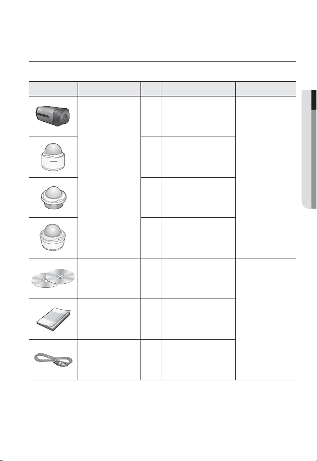
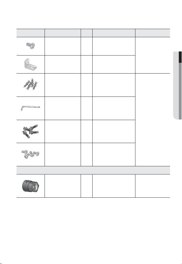
WHAT’S INCLUDED
UNLOCK
Please check if your camera and accessories are all included in the product package.
Appearance Item Name
Quantity
1
Description Model Name
● OVERVIEW
1
Camera
1
SNB-7002 or
SND-7082 or
SND-7082F or
SNV-7082
1
Instruction book,
Installer S/W CD,
2
CMS S/W DVD
SNB-7002/
Quick Guide
(Optional)
1
SND-7082/
SND-7082F/
SNV-7082
Cable for the testing
monitor
Used to test the camera
1
connection to a portable display
device
English _11
overview
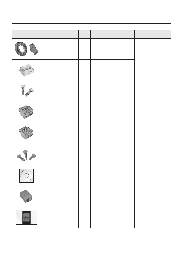
Appearance Item Name
C Mount Adapter,
Auto Iris Lens Connector
Camera Holder (Mount) 1
Camera Holder (Mount)
Screws
6-position Terminal Block
5-position Terminal Block
Iron Screw 3 Used for fixing to an iron plate
Template
Jack Modular 1 LAN cable gender
Quantity
1
2 Used to install the mount
1
1
1
Description Model Name
Used to install the C Mount
camera lens
Used to install the camera
holder
Used for alarm in/out terminals
Used for alarm in/out terminals
Product installation guide
SNB-7002
SND-7082/
SND-7082F/
SNV-7082
SND-7082/
SND-7082F
SND-7082F/
SNV-7082
12_ overview
Dustproof Plate 1
Prevents dust ingress into the
wiring connection part.
SND-7082
Appearance Item Name
Tapping Screw 1 Used to fix the safety bracket
Bracket Safety 1 Safety Bracket
Quantity
Description Model Name
SND-7082F
● OVERVIEW
ASSY-Tapping Screw
L Wrench
Plastic Anchor
Machine Screws 4
Lens Options (not included)
CS/C Lens
Used for installation on the wall
4
1
or ceiling
Used to remove/
fix the dome cover
For fixing a screw,
4
Inserted in a hole
(reinforced anchoring force)
Used for assembling the dome
case when installing the product
on the pipe, wall mount, etc. or
blocking a hole.
Optional lens to be inserted in
a camera
SNV-7082
SNB-7002
English _13
overview
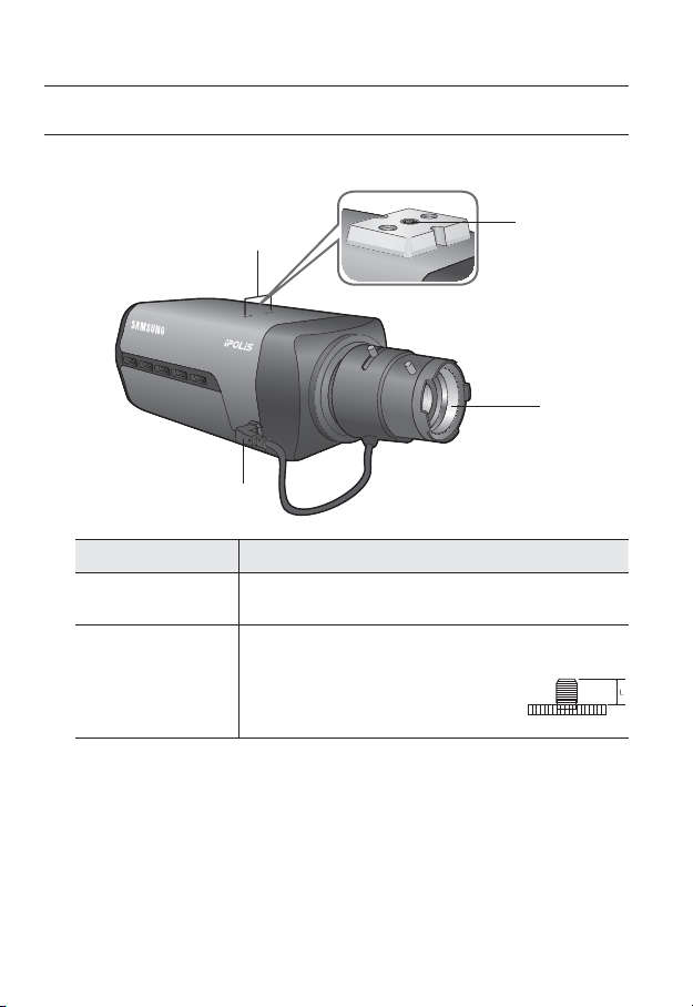
AT A GLANCE (SNB-7002)
Front Side
Item Description
Camera Holder
(Mount) Holes
Mounting Bracket
b
Screw Hole
Used when you mount the camera onto the bracket by fixing the camera
holder (mount) adaptor with the bracket.
Used to fix the camera on a bracket or mounting bracket.
The screw size : use this screw to fix the mounting bracket.
1/4" - 20UNC (20THREAD)
L : 4.5mm±0.2mm (ISO Standard) or 0.197" (ASA
Standard)
b
<Fixed Bracket>
c
14_ overview

Item Description
Auto Iris Lens
c
(Optional)
Auto Iris Lens
Connector
Wipe out a dirty surface of the lens softly with a lens tissue or cloth to which you have applied
M
ethanol.
Mounting Bracket is not included.
For more information to use mounting bracket, refer to the product’s documentation.
Installed on the lens adaptor.
Used to supply power and output signal to control the iris of the lens.
● OVERVIEW
English _15
overview
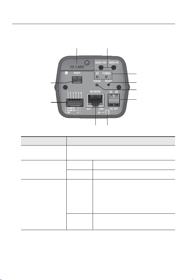
Rear Side
Item Description
SD Memory Card
Compartment
Audio terminal
b
SD, Power Indicators
c
b
c
Compartment for the SD memory card.
AUDIO OUT Used to connect to speakers.
AUDIO IN Used to connect to a microphone.
ON : A memory card is inserted and operates normally.
Flashing :
SD
POWER
Failed to record, insufficient space, or inserted
abnormally.
OFF : Camera is off, camera is restarting, memory card is
not in place, or when record is off.
ON : While the power is on
OFF : If the power is off
16_ overview
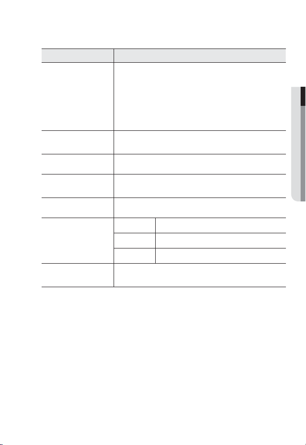
Item Description
The button restores all camera settings to the factory default.
Press and hold for about 5 seconds to reboot the system.
If you reset the camera, the network settings will be adjusted so that
Reset Button
Focus Adjustment
Button
Power Port Used to plug the power cable.
Lightning protective
grounding port
Network Port Used to connect the PoE or Ethernet cable for network connection.
Alarm I/O Port
Test Monitor Out
J
DHCP can be enabled. If there is no DHCP server in the network, you
must run the IP Installer program to change the basic network settings
such as IP address, Subnet mask, Gateway, etc., before you can connect
to the network.
The button adjusts the focus of image automatically.
Used to discharge the lightning current safely outside in order to protect the
camera.
ALARM IN Used to connect the alarm input signal.
ALARM OUT
GND Used for earth-grounding.
Output port for test monitoring the video output. Use the test monitor cable
to connect to a mobile display and check the test video.
Used to connect the alarm output signal.
● OVERVIEW
English _17
overview
UNLOCK
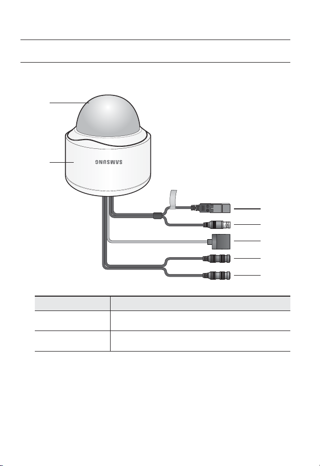
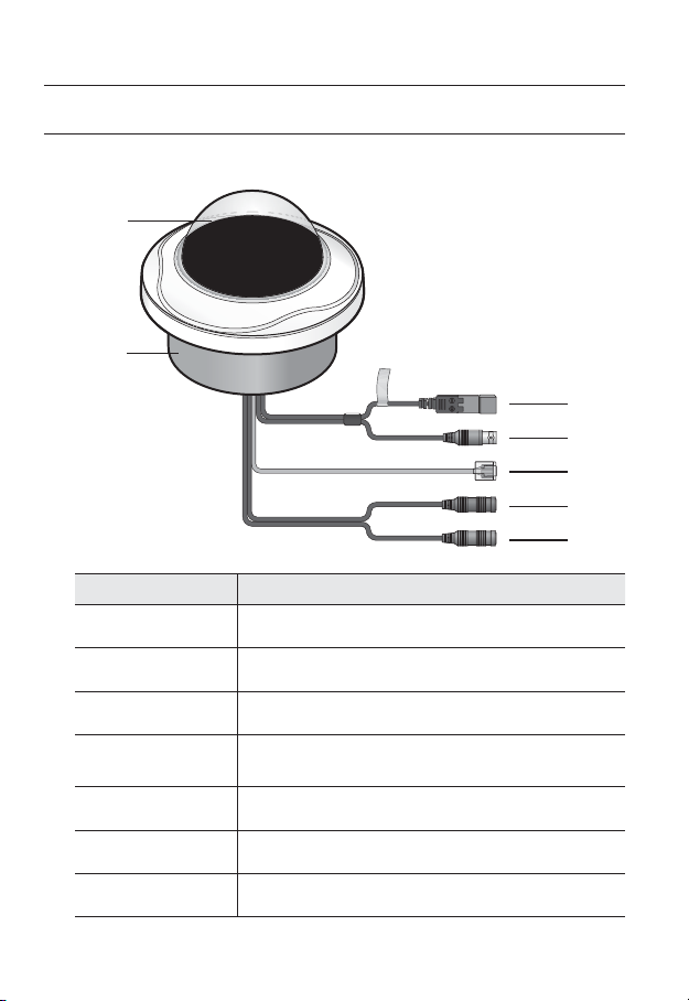
AT A GLANCE (SND-7082)
Appearance
b
Item Description
Top cover
Case cover used to protect the lens and the main unit.
c
Camera Case
b
18_ overview
Housing part that covers the camera body.
Item Description
c
Power Port
Test Monitor Out
Used to plug the power cable.
Output port for test monitoring the video output. Use the test monitor cable
to connect to a mobile display and check the test video.
● OVERVIEW
Network Port
Audio In Jack
Audio Out Jack
Used to connect the PoE or Ethernet cable for network connection.
Used to connect to a microphone.
Used to connect to speakers.
English _19
overview
UNLOCK
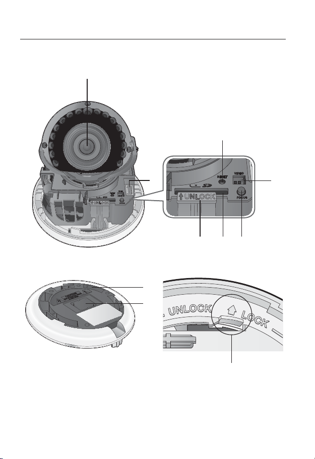
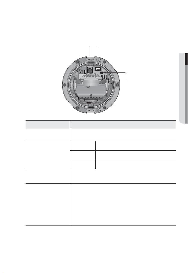
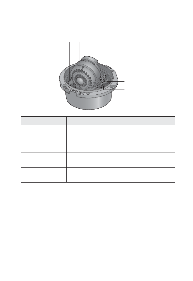
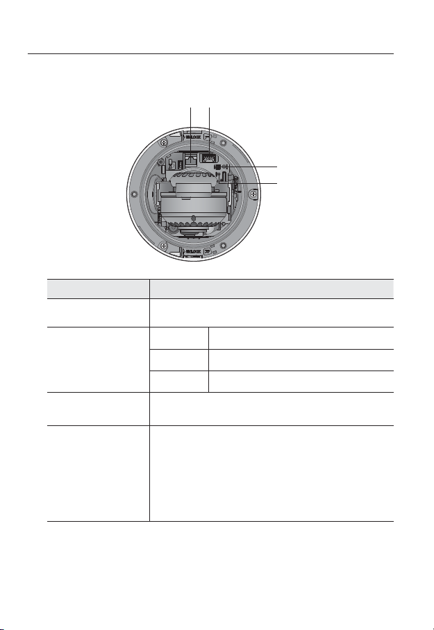
Components
c
20_ overview
UNLOCK
b
Item Description
Lens Lens for the camera.
ALARM IN Used to connect the alarm input signal.
Alarm I/O Port
b
Reset Button
c
Test Monitor Out
Focus Adjustment
Button
SD Memory Card
Compartment
Lock Release Lever
Bracket Used to install the camera on the wall or ceiling with the screws.
Wiring Cover
Release Lock
ALARM OUT Used to connect the alarm output signal.
GND Used for earth-grounding.
The button restores all camera settings to the factory default.
Press and hold for about 5 seconds to reboot the system.
If you reset the camera, the network settings will be adjusted so that
J
DHCP can be enabled. If there is no DHCP server in the network, you
must run the IP Installer program to change the basic network settings
such as IP address, Subnet mask, Gateway, etc., before you can
connect to the network.
Output port for test monitoring the video output. Use the test monitor cable
to connect to a mobile display and check the test video.
The button adjusts the focus of image automatically.
Compartment for the SD memory card.
Press the <UNLOCK> levers on both ends to separate camera module from
the body.
If you drill a hole in the wiring cover for wiring,
remove the cover and attach the provided
dustproof plate to it, and arrange the cables
through the plate.
If you want to remove the bracket from the main unit or remove the camera
from the bracket, push this out and turn the main unit in the <UNLOCK>
direction.
● OVERVIEW
English _21
overview
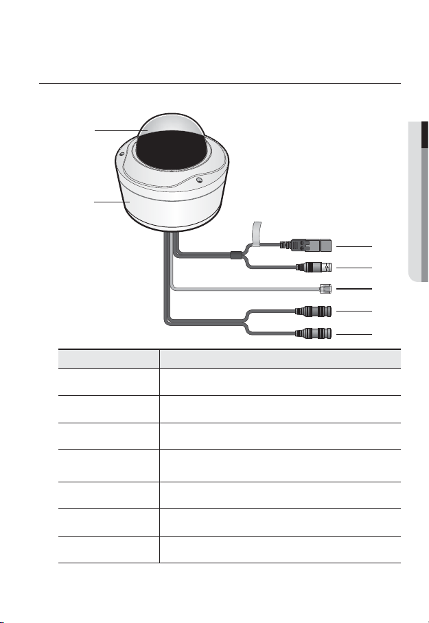
AT A GLANCE (SND-7082F)
Appearance
b
Item Description
Top cover
Case cover used to protect the lens and the main unit.
c
Camera Case
b
Power Port
c
Test Monitor Out
Network Port
Audio In Jack
Audio Out Jack
22_ overview
Housing part that covers the camera body.
Used to plug the power cable.
Output port for test monitoring the video output. Use the test monitor cable
to connect to a mobile display and check the test video.
Used to connect the PoE or Ethernet cable for network connection.
Used to connect to a microphone.
Used to connect to speakers.
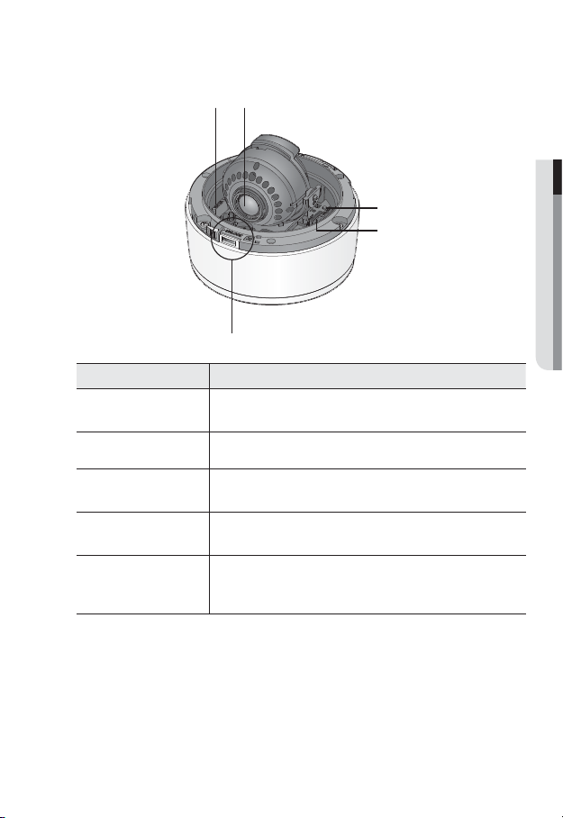
Components
b
c
Item Description
Network Port Used to connect the PoE or Ethernet cable for network connection.
ALARM IN Used to connect the alarm input signal.
b
c
Alarm I/O Port
Test Monitor Out
Reset Button
ALARM OUT
GND Used for earth-grounding.
Output port for test monitoring the video output. Use the test monitor cable
to connect to a mobile display and check the test video.
The button restores all camera settings to the factory default.
Press and hold for about 5 seconds to reboot the system.
If you reset the camera, the network settings will be adjusted so that
J
DHCP can be enabled. If there is no DHCP server in the network, you
must run the IP Installer program to change the basic network settings
such as IP address, Subnet mask, Gateway, etc., before you can
connect to the network.
Used to connect the alarm output signal.
● OVERVIEW
English _23
overview
Item Description
Lock Release Lever
Lens Lens for the camera.
Focus Adjustment
Button
SD Memory Card
Compartment
Press the <UNLOCK> levers on both ends to separate camera module from
the body.
The button adjusts the focus of image automatically.
Compartment for the SD memory card.
24_ overview
AT A GLANCE (SNV-7082)
Appearance
b
Item Description
Top cover
Case cover used to protect the lens and the main unit.
● OVERVIEW
c
b
c
Camera Case
Power Port
Test Monitor Out
Network Port
Audio In Jack
Audio Out Jack
Housing part that covers the camera body.
Used to plug the power cable.
Output port for test monitoring the video output. Use the test monitor cable
to connect to a mobile display and check the test video.
Used to connect the PoE or Ethernet cable for network connection.
Used to connect to a microphone.
Used to connect to speakers.
English _25
overview
Components
Item Description
Network Port Used to connect the PoE or Ethernet cable for network connection.
Alarm I/O Port
b
Test Monitor Out
c
Reset Button
b
c
ALARM IN Used to connect the alarm input signal.
ALARM OUT
GND Used for earth-grounding.
Output port for test monitoring the video output. Use the test monitor cable
to connect to a mobile display and check the test video.
The button restores all camera settings to the factory default.
Press and hold for about 5 seconds to reboot the system.
If you reset the camera, the network settings will be adjusted so that
J
DHCP can be enabled. If there is no DHCP server in the network, you
must run the IP Installer program to change the basic network settings
such as IP address, Subnet mask, Gateway, etc., before you can
connect to the network.
Used to connect the alarm output signal.
26_ overview
Item Description
Lock Release Lever
Lens Lens for the camera.
Focus Adjustment
Button
SD Memory Card
Compartment
Release Lock
Press the <UNLOCK> levers on both ends to separate camera module from
the body.
The button adjusts the focus of image automatically.
Compartment for the SD memory card.
If you want to remove the bracket from the main unit or remove the camera
from the bracket, push this out and turn the main unit in the <UNLOCK>
direction.
● OVERVIEW
English _27
installation & connection
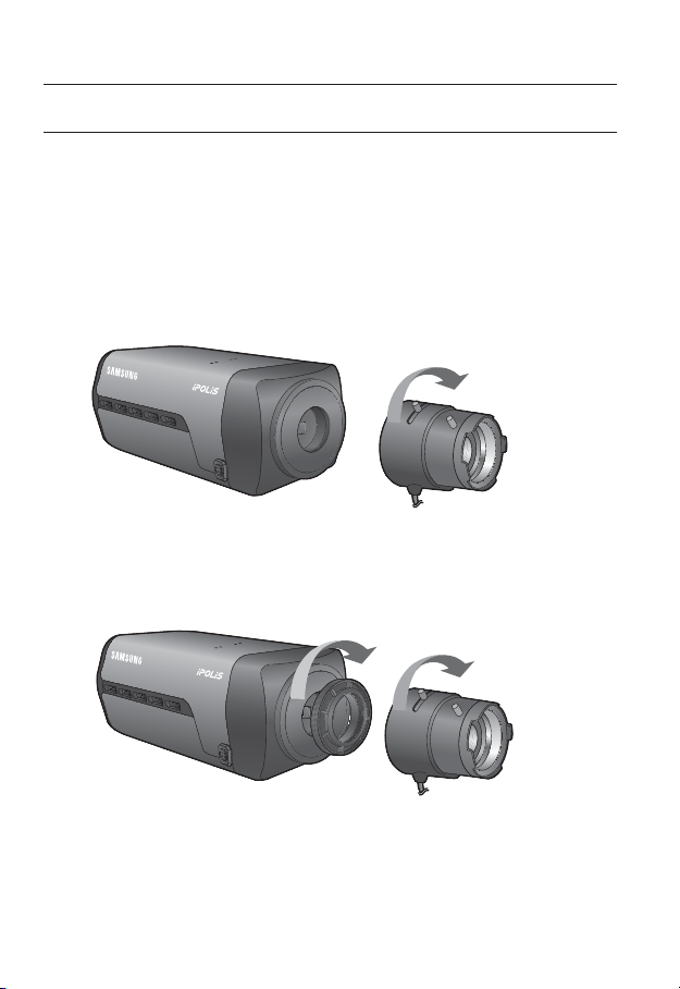
MOUNTING THE LENS (SNB-7002)
Disconnect the power before proceeding.
The C lens and CS lens are not included in the product package.
M
It is recommended that megapixel lens are use on this camera to optimise performance.
Mounting the CS lens on a camera
Turn the optional CS lens clockwise to insert it.
Mounting the C lens on a camera
Turn the C mount adaptor clockwise to insert it and do the same with the C lens.
CS Lens
28_ installation & connection
C Lens
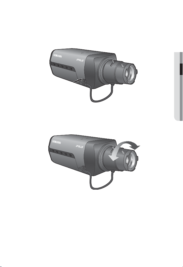
Connecting the Auto Iris Lens connector
Insert the lens connector into the corresponding hole of the camera.
● INSTALLATION & CONNECTION
Focusing
Turn the lens left or right to control the zoom and focus the lens so that you can view a clear,
sharp object.
English _29
installation & connection
Precautions before installation
Ensure you read out the following instructions before installing the camera:
• When installing on a ceiling or wall, desir
times of the camera’s weight.
• Stuck-in or peeled-off cables can cause damage to the product or a fire.
• For safety purposes, keep anyone else away from the installation site.
And put aside personal belongings from the site, just in case.
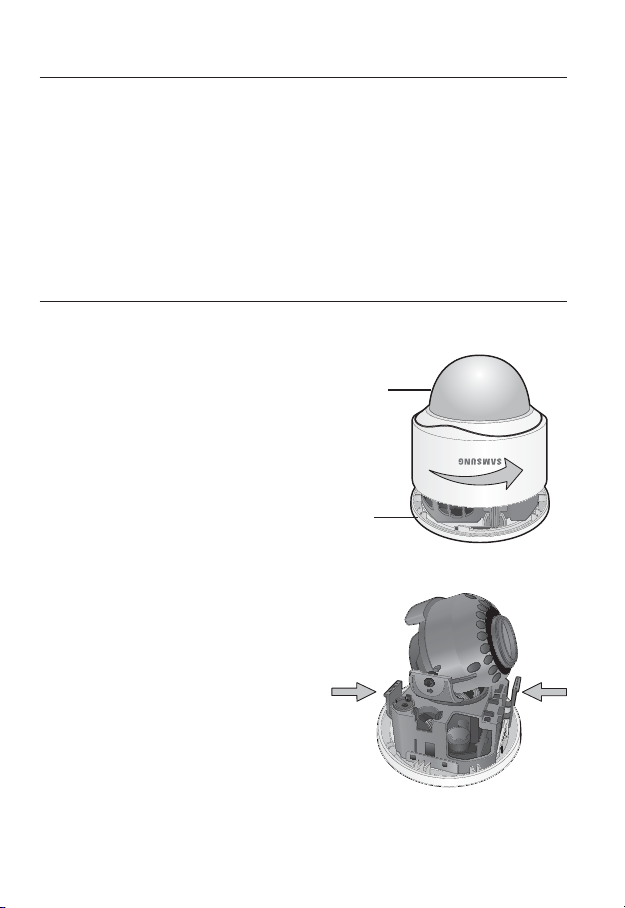
INSTALLATION (SND-7082)
Disassembling
1. Take the camera body with one hand
and take the top cover with the other
hand. Then, turn the cover counter
clockwise to remove it.
ess the <UNLOCK> levers on both ends
2. Pr
to separate camera module from the body.
ed spot must be capable of supporting at least 5
Top cover
Camera Body
UNLOCK
30_ installation & connection
 Loading...