

Page 1

NETWORK CAMERA
Quick Guide
SND-7080F
English
Page 2
2_ English2
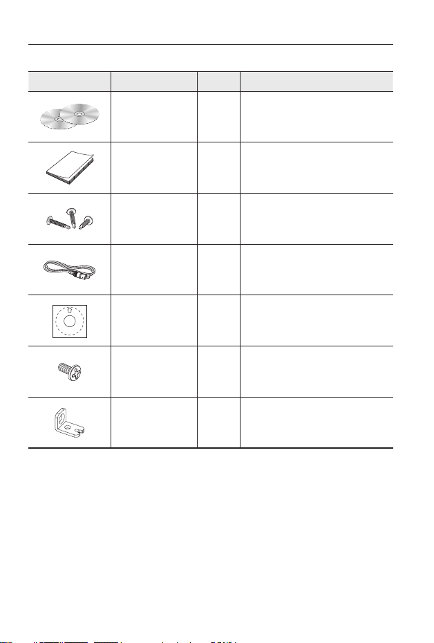
WHAT’S INCLUDED
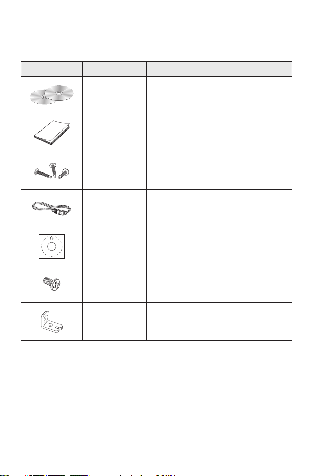
Please check if your camera and accessories are all included in the product package.
Appearance Item Name Quantity Description
User Manual,
Installer S/W DVD,
CMS S/W DVD
2
Quick Guide 1
Iron Screw 3 Used for fixing to an iron plate
Cable for the testing
monitor
1
Used to test the camera connection to a
portable display device
Template 1 Product installation guide
Tapping Screw 1 Used to fix the safety bracket
Bracket Safety 1 Safety Bracket
Page 3
English
English _3
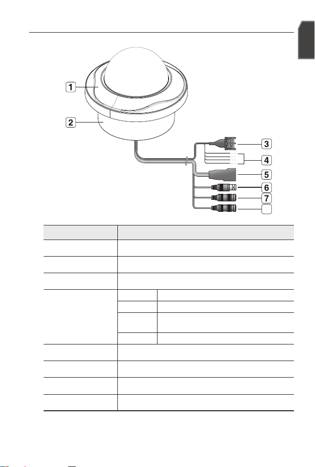
AT A GLANCE
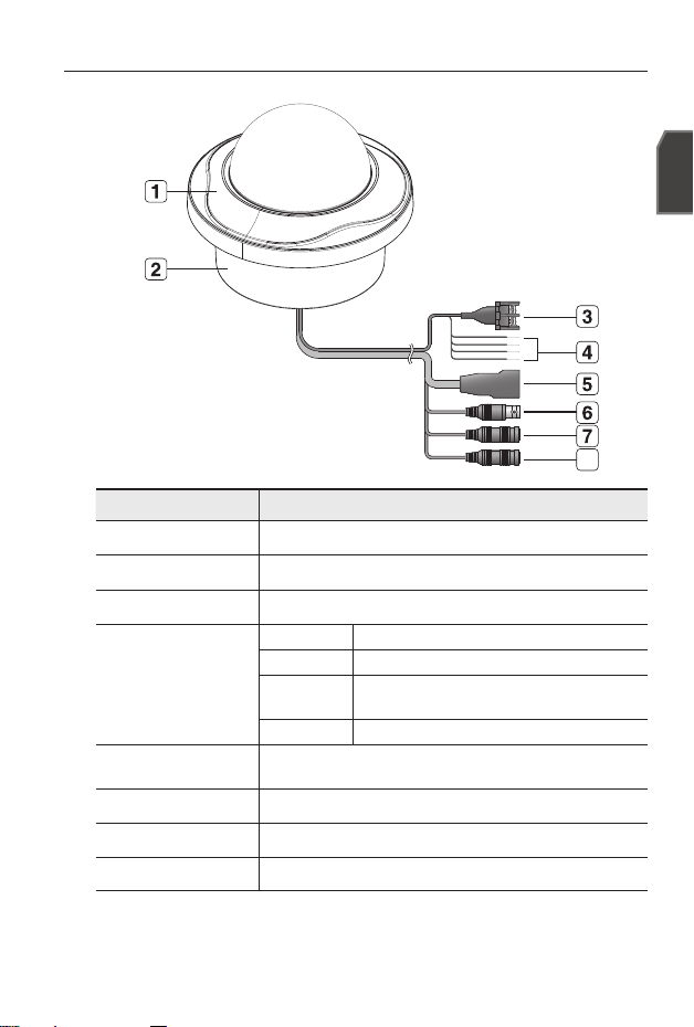
Appearance
Item Description
a
Top cover Case cover used to protect the lens and the main unit.
b
Camera Case Covers the lens and camera body.
c
Power Port Used to plug the power cable.
d
Alarm In /
Out terminals
ARM-IN BLUE : Used to connect the alarm input signal.
ARM-OUT WHITE : Used to connect the alarm output signal.
A-COM
GRAY : Common port where the alarm output signal is
connected.
GND YELLOW : Used for earth-grounding.
e
Network Port Used to connect a PoE or LAN cable.
f
Video Out Port Analog video output port. (for installation)
g
Audio In Jack Used to connect to a microphone.
h
Audio Out Jack Used to connect to speakers.
8
Page 4
4_ English4
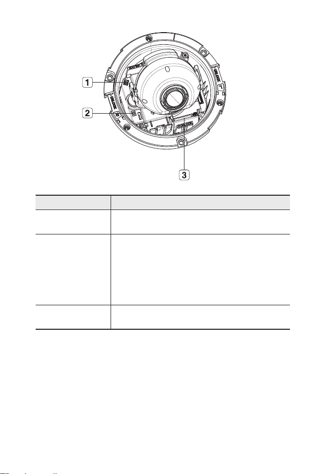
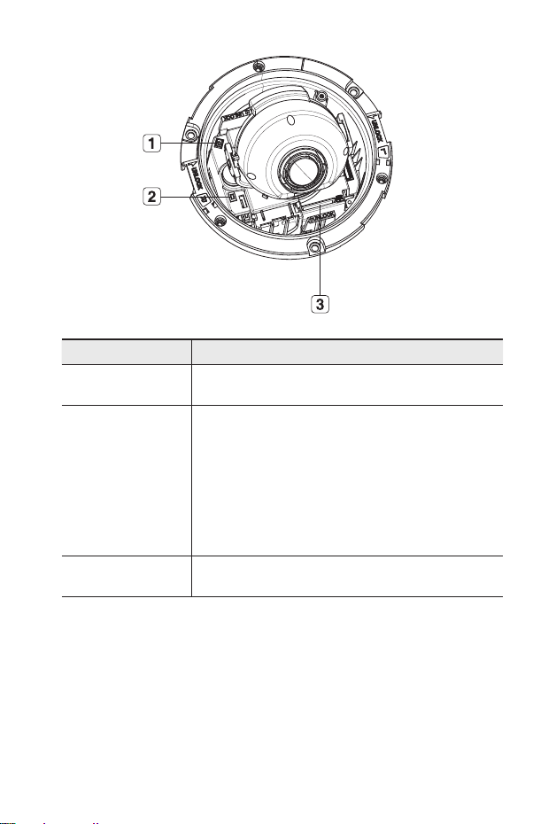
Inside
Item Description
a
Monitor Out
Using the test monitor cable, you can connect to a mobile display for camera
test.
b
Reset Button
Resets the camera settings to the default. Press and hold it for about 5
seconds to turn off the system indicator and restart the system.
J
If you reset the camera, the network settings will be adjusted so that
DHCP can be enabled. If there is no DHCP server in the network, you
must run the IP Installer program to change the basic network settings
such as IP address, Subnet mask, Gateway, etc., before you can
connect to the network.
c
SD Memory Card
Compartment
Compartment for the SD memory card.
Page 5
English
English _5
INSTALLATION
Precautions before installation
Ensure you read out the following instructions before installing the camera:
Select an installation site (ceiling or wall) that can endure at least 5 times of the
camera weight.
Stuck-in or peeled-off cables can cause damage to the product or a fire.
For safety purposes, keep anyone else away from the installation site. And put aside
personal belongings from the site, just in case.
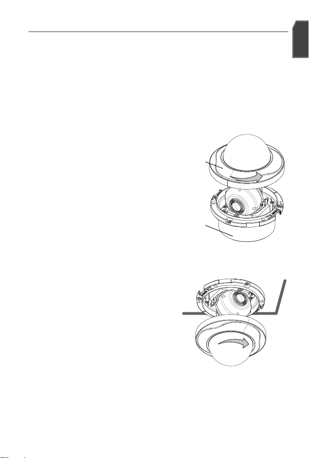
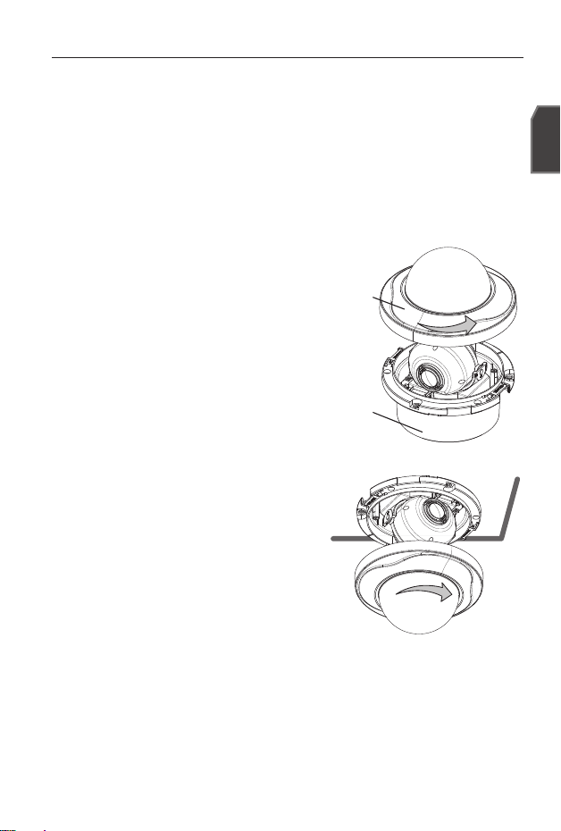
Disassembling
Take the camera body with one hand and take the
top cover with the other hand. Then, turn the cover
counter clockwise to remove it.
Installation
Use the provided template to drill one hole for
the camera, and one for the screw (5 mm in
diameter, at least 35 mm in depth), and insert
the plastic anchor (HUR 5) to the end of the
screw hole.
Connect and arrange the necessary cables
lest that they should be damaged or twisted
while installing the camera.
Insert the camera body into the hole so that it
fits to the camera hole, and fix the body using
the ASSY tapping screws (TH M4xL30). (x3)
Refer to “Adjusting the monitoring direction for the camera” to adjust the lens in a
desired direction.
Close the top cover.
Fit the top cover into the fixing tips of the camera body and turn the cover clockwise.
1.
1.
2.
3.
4.
5.
Top cover
Camera Body
Page 6

6_ English6
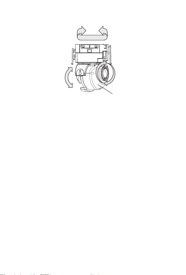
Adjusting the monitoring direction for the camera
Adjusting the monitoring direction
You can adjust the camera direction only when the camera is fixed on the ceiling.
Where, rotating the camera unit to the left or right is called Pan, adjusting the tilt is called
Tilt, and turning the lens on its axis is called Rotate.
The effective range of pan is a total of 355 degrees.
The effective range of rotation is a total of 355 degrees.
The effective range of tilt is a total of 90 degrees.
In some angles, the top cover may cause cutting some part of the monitoring object.
Do not rotate the focus/zoom lens by force after removing the cover front.
Otherwise, it may cause an incorrect focus due to a motor failure.
Methods of adjustment
After installing the camera, adjust the panning angle in consideration of the
monitoring direction.
When tilting the camera, you should adjust the horizontal angle lest that the image
be displayed reversely.
Adjust the rotation angle to correct the image display position (up/down/left/right).
Rotating means rotation on the basis of the rear lens unit.
Adjust the tilt angle so that the camera faces toward the monitoring object.
❖
-
-
-
J
❖
1.
2.
3.
Panning
Tilting
Lens rotation
Cover Front
Page 7
English
English _7
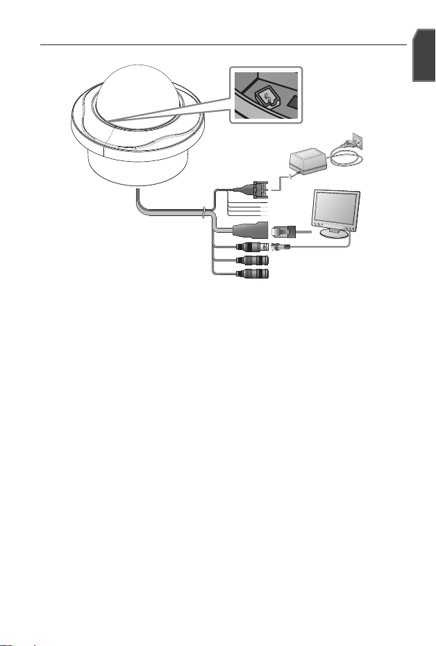
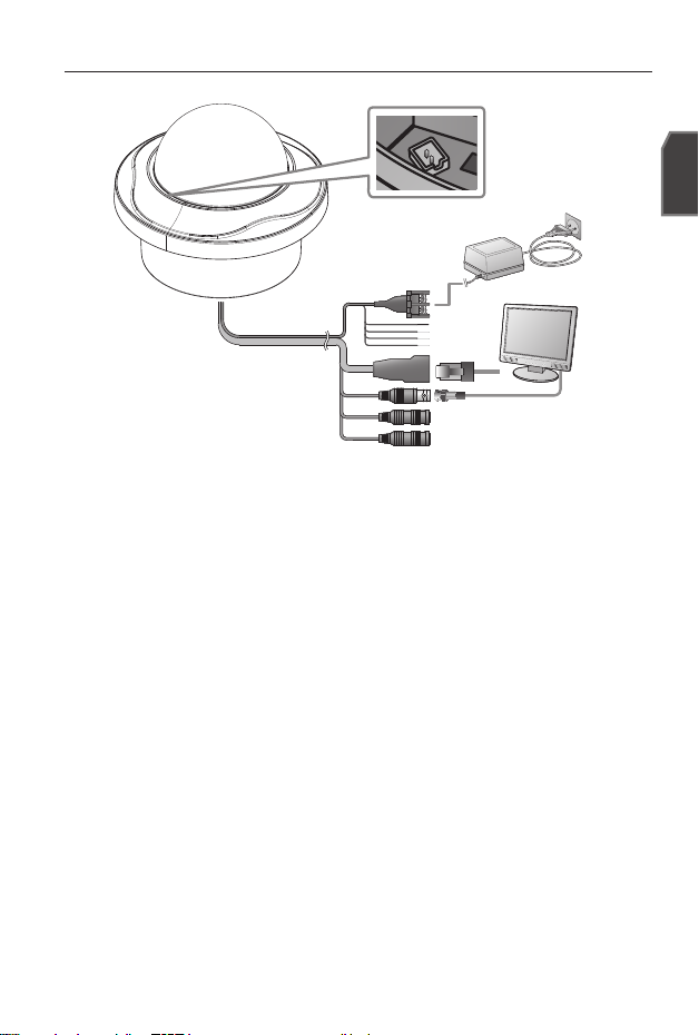
CONNECTING WITH OTHER DEVICE
Connecting to the monitor
Connect the video out port of the camera to the video input port of the monitor.
In the initial installation of the camera, you can connect the camera to the monitor for checking
the connection status.
You can set the video output type to either NTSC or PAL.
Ethernet Connection
Connect the Ethernet cable to the local network or to the Internet.
Power Supply
Use the screwdriver to connect each line (+, –) of the power cable to the corresponding
power port of the camera.
Be careful not to reverse the polarity when you connect the power cable.
You can also use a router featuring PoE (Power over Ethernet) to supply power to the camera.
If PoE and DC 12V are both applied, this camera will get supplied with power from PoE.
Please make sure the monitor and camera are turned off when connecting them.
M
J
Monitor
Power
Ethernet
Monitor Out
Page 8
8_ English8
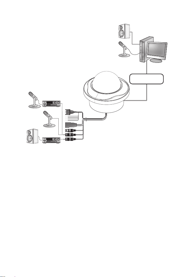
Connecting to Audio Input/Output
Connect the AUDIO IN port of the camera with the microphone directly or LINE OUT
port of the amplifier that the microphone is connected to.
Connect the AUDIO OUT port of the camera with the LINE IN port of the speaker.
Check the specifications for audio input.
Audio Codec
G.711 PCM. μ-law 64kbps 8kHz sampling
Full duplex Audio
Audio in
Used for mono signal line input (Max.2.4 Vpp)
Audio out
Used for mono signal line output (Max.2.4 Vpp)
Line out impedance
600Ω
1.
2.
3.
PC
Network
Speaker
Microphone
Amp
Amp
Microphone
Microphone
Speaker
Page 9
English
English _9
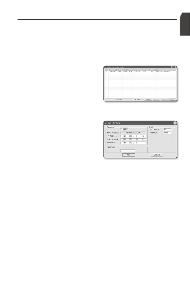
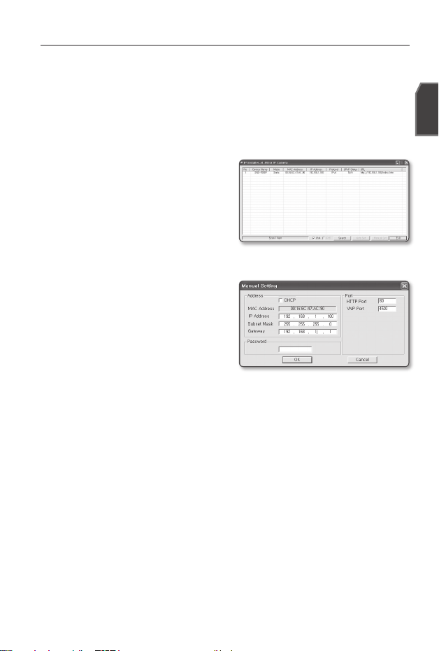
IP SETUP
Manual Network Setup
Run <IP Installer_vX.XX.exe> to display the camera search list.
At the initial startup, both [Auto Set] and [Manual Set] will be grayed out.
For cameras found with the IPv6 setting, these buttons will be grayed out as the cameras do not
support this function.
Select a camera in the search list.
Find the MAC (Ethernet) address
labeled on the rear of the camera.
Both the [Auto Set] and [Manual Set]
buttons will be activated.
Click [Manual Set].
The Manual Setting dialog appears.
The default values of <IP Address>,
<Subnet Mask>, <Gateway>, <HTTP Port> and <VNP Port> of the camera will
be displayed.
In the <Address> pane, provide the
necessary information.
MAC (Ethernet) Address : The MAC
(Ethernet) address of the applicable
camera will be set automatically so
you don't need to input it manually.
You can configure the static IP settings
only if the DHCP checkbox is unchecked.
In the <Port> pane, provide necessary information.
HTTP Port : Used to access the camera using the Internet browser, defaulted to
80. Use the spin button to change the HTTP Port value.
VNP Port : Used to control the video signal transfer, defaulted to 4520.
Enter the password.
This is the login password for the “admin” user who accesses the camera.
The default password is “4321”.
Click [OK].
Manual network setup will be completed.
M
1.
2.
3.
M
4.
5.
6.
Page 10
10_ English10
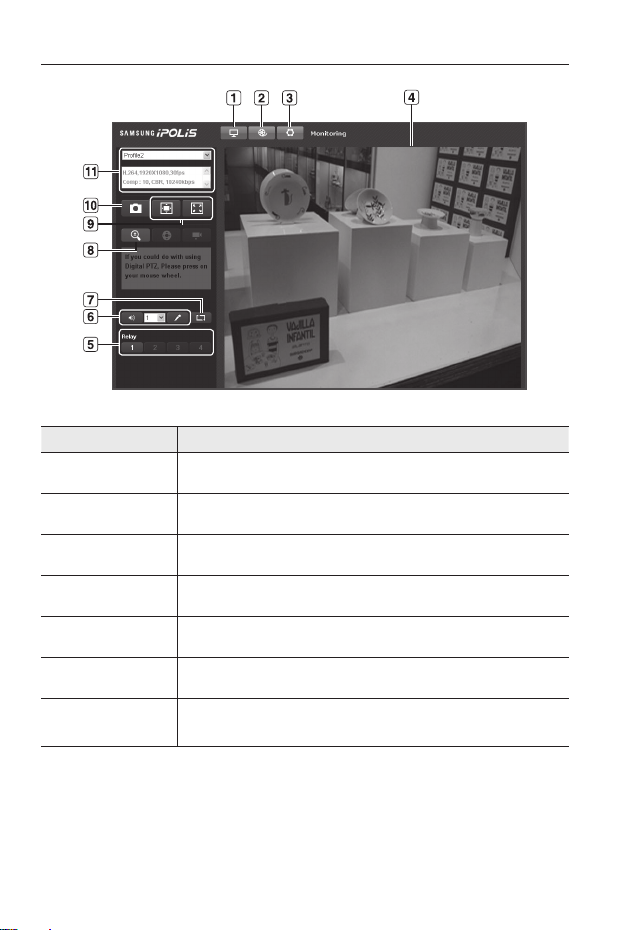
USING THE LIVE SCREEN
Item Description
a
Monitoring Move to the monitoring screen.
b
Playback Switch to the monitoring screen that plays recording data in the SD memory.
c
Setup Move to the Setup screen.
d
Viewer Screen Displays the Live video on the screen.
e
Alarm Output Activate the Alarm Out port.
f
Audio Display the audio Listen and Talk toggle button on the screen.
g
Hide the alarm
indicator
Hides the alarm indicator near the border of the viewer screen.
Page 11

English
English _11
Item Description
h
Digital zoom You can use the mouse wheel to activate the digital zooming.
i
Screen
Optimization,
Full Screen
Adjust the screen to the optimal size, and display the Full Screen icon on the Live
screen.
j
Capture Saves the snapshot as an image file in the .bmp format.
k
Video Format
You can select a profile type in <Video profile> under the <Audio & Video> setup
menu.
If the “Invalid codec” message is displayed, select a profile type from the profile
list again.
M
If the temperature drops below the operational range, video signal may not be produced. In such
cases, please wait for the video.
Web pages related to playback and setting menus are accessible only by the admin. For other
user accounts, the buttons will be deactivated.
M
Page 12

Samsung Techwin cares for the environment at all product manufacturing stages, and is
taking measures to provide customers with more environmentally friendly products.
The Eco mark represents Samsung Techwin’s devotion to creating environmentally friendly
products, and indicates that the product satisfies the EU RoHS Directive.
Page 13

Page 14

SALES NETWORK
SAMSUNG TECHWIN CO., LTD.
Samsungtechwin R&D Center, 701, Sampyeong-dong, Bundang-gu, Seongnam-si, Gyeonggi-do, Korea, 463-400
TEL : +82-70-7147-8740~60 FAX : +82-31-8018-3745
SAMSUNG TECHWIN AMERICA Inc.
100 Challenger Rd. Suite 700 Ridgefield Park, NJ 07660
Toll Free : +1-877-213-1222 Direct : +1-201-325-6920
Fax : +1-201-373-0124
www.samsungcctvusa.com
SAMSUNG TECHWIN EUROPE LTD.
Samsung House, 1000 Hillswood Drive, Hillswood Business
Park Chertsey, Surrey, UNITED KINGDOM KT16 OPS
TEL : +44-1932-45-5300 FAX : +44-1932-45-5325
www.samsungtechwin.com
www.samsungsecurity.com
www.samsungipolis.com
Page 15

CAMÉRA RÉSEAU
Guide de prise en main rapide
SND-7080F
Français
Page 16
2_ Français2
CONTENU
Veuillez vérifier si votre caméra et l’ensemble de ses accessoires sont contenus dans l’emballage
du produit.
Apparence Nom de l'élément Quantité Description
Manuel d’utilisation, DVD
du logiciel Installer, DVD
du logiciel CMS
2
Guide de prise en main
rapide
1
Vis métallique 3 Permet la fixation à une plaque métallique
Câble pour l'écran de test 1
Permet de tester la connexion de la caméra à un
dispositif d'affichage portable
Gabarit 1 Guide d'installation du produit
Vis autotaraudeuse 1 Sert à fixer le support de sécurité
Support de sécurité 1 Support de sécurité
Page 17
Français _3
Français
D’UN COUP D’ŒIL
Apparence
Élément Description
a
Couvercle supérieur Couvercle du boîtier utilisé pour protéger l'objectif et l'unité principale.
b
Boîtier de la caméra Couvre l’objectif et le corps de la caméra.
c
Port d'alimentation Utilisé pour la connexion du câble d’alimentation.
d
Bornes E/S Alarme
ARM-IN
BLUE : Utilisé pour la connexion du signal d’entrée de l’alarme.
ARM-OUT
WHITE : Utilisé pour la connexion du signal de sortie de l’alarme.
A-COM
GRAY : Port commun sur lequel le signal de sortie de
l'alarme est connecté.
GND YELLOW : Utilisé pour la mise à la terre.
e
Port Réseau
Utilisé pour connecter l'Alimentation électrique par câble Ethernet ou le
câble LAN.
f
Port de sortie vidéo Port de sortie de la vidéo analogique. (pour l’installation)
g
Prise d’entrée audio Utilisée pour la connexion à un microphone.
h
Prise de sortie audio Utilisée pour la connexion aux enceintes.
8
Page 18
4_ Français4
À l'intérieur
Élément Description
a
Sortie d’écran
Le Cable de l'ecran test est connecté à un affichage portable et sert à tester
la caméra.
b
Bouton de
réinitialisation
Réinitialise les réglages de la caméra. Appuyez sur ce bouton pendant 5
secondes environ pour éteindre le voyant du système et faire redémarrer ce
dernier.
J
Si vous réinitialisez la caméra, les réglages réseau seront ajustés de
sorte que le serveur DHCP puisse être activé. En l’absence de serveur
DHCP au sein du réseau, vous devez lancer le programme d’installation
IP Installer pour modifier les réglages réseau de base, tels que l'adresse
IP, le masque de sous-réseau, la passerelle, etc., avant de pouvoir vous
connecter au réseau.
c
Compartiment de la
carte mémoire SD
Compartiment de la carte mémoire SD.
Page 19
Français _5
Français
INSTALLATION
Précautions à prendre avant l'installation
Assurez-vous de bien lire les instructions suivantes avant d'installer la caméra.
Sélectionnez un site d'installation (plafond ou mur) capable de supporter un poids
équivalent à cinq fois celui de la caméra.
L'utilisation de câbles recollés ou effilochés peut endommager le produit et provoquer
un incendie.
Pour des raisons de sécurité, ne laissez personne d'autre que vous sur le site de l'installation.
Ne laissez pas vos effets personnels sur le site, par mesure de précaution.
Démontage
Tenez le corps de la caméra d’une main et le couvercle
supérieur de l’autre. Ensuite, tournez le couvercle dans
le sens inverse des aiguilles d’une montre
pour le retirer.
Installation
Utilisez le gabarit fourni afin de percer un
trou pour la caméra et un trou pour la vis (5
mm de diamètre, profondeur supérieure à 35
mm), puis insérez complètement la bride d’
ancrage en plastique (HUR 5) dans le trou de
la vis.
Connectez et disposez les câbles nécessaires
de sorte à éviter de les endommager ou de
les coincer lors de l'installation de la caméra.
Insérez le corps de la caméra dans le trou
en l'alignant sur le trou correspondant à la
caméra, puis fixez le corps à l'aide des vis autotaraudeuses de MONTAGE (TH,
M4xL30). (x3)
Reportez-vous à la section « Réglage de l'orientation de la caméra de surveillance »
pour régler l’objectif selon la direction souhaitée.
Fermez le couvercle supérieur.
Insérez le couvercle supérieur dans les embouts de fixation sur le corps de la caméra et tournez le
couvercle dans le sens des aiguilles d’une montre.
1.
1.
2.
3.
4.
5.
Couvercle
supérieur
Corps de la
caméra
Page 20
6_ Français6
Réglage de l'orientation de la caméra de surveillance
Réglage de la direction de surveillance
Vous ne pouvez régler l'orientation de la caméra que lorsque celle-ci a été fixée au plafond.
La rotation de l’unité de la caméra vers la gauche ou la droite est appelée Pan ou
panoramique, le réglage de l’inclinaison est appelé Orientation et la rotation de l’objectif sur
son axe est appelée Rotation.
La plage effective du panoramique couvre un angle total de 355 degrés.
La plage effective de la rotation couvre un angle total de 355 degrés.
La plage effective de l’inclinaison couvre un angle total de 90 degrés.
Pour certains angles, le couvercle supérieur peut tronquer certaines parties de l’objet à
surveiller.
Ne tournez pas l’objectif de mise au point/zoom en forçant dessus après avoir retiré le
couvercle avant. Autrement, ceci peut fausser la mise au point en raison d’une panne de
moteur.
Méthodes de réglage
Après l’installation de la caméra, réglez l’angle de panoramique selon la direction de
surveillance.
Lors de l'orientation de la caméra, vous devez régler l'angle horizontal de sorte que l’
image ne s’affiche pas de manière inversée.
Réglez l’angle de rotation pour corriger la position d’affichage de l’image (haut/bas/
gauche/droit).
La rotation désigne la rotation de l'objectif arrière de l'unité.
Réglez l’angle d’inclinaison de sorte que la caméra soit face à l’objet à surveiller.
❖
-
-
-
J
❖
1.
2.
3.
Panoramique
Inclinaison
horizontale/
verticale
Rotation de l’objectif
Couvercle avant
Page 21
Français _7
Français
CONNEXION À D’AUTRES PÉRIPHÉRIQUES
Connexion à l’écran
Reliez le port de sortie vidéo de la caméra au port d’entrée vidéo du moniteur.
Au cours de l'installation initiale de la caméra, vous pouvez connecter la caméra à l'écran pour
vérifier l'état de connexion.
Vous pouvez régler le type de sortie vidéo sur NTSC ou PAL.
Connexion Ethernet
Connectez le câble Ethernet au réseau local ou à Internet.
Alimentation
Utilisez le tournevis pour connecter les lignes du câble d’alimentation (+, –) au port
correspondant de la caméra.
Prenez soin de ne pas inverser la polarité en connectant le câble d’alimentation.
Vous pouvez également utiliser un routeur doté d'une alimentation électrique par câble Ethernet
pour fournir le courant à la caméra.
En cas d’application simultanée d’un PoE et d’un courant CC 12 V, la caméra est alimentée à
partir du PoE.
Assurez-vous que le moniteur et la caméra sont désactivés avant de les relier.
M
J
Écran
Alimentation
Ethernet
Sortie d’écran
Page 22

8_ Français8
Connecter à l'entrée/la sortie Audio
Connecter le port AUDIO IN de la caméra avec le microphone directement ou le port
SORTIE DE LIGNE de l'amplificateur auquel le microphone est connecté.
Connecter le port AUDIO OUT de la caméra et le port ENTREE DE LIGNE du haut
parleur.
Vérifiez les spécifications pour l'entrée audio.
Codec audio
G.711 PCM, μ-law 64kbps 8kHz sampling
Audio duplex complet
Entrée audio
Utilisé pour l'entrée de ligne de signal mono (Maxi. 2,4 Vpp)
Sortie audio
Utilisé pour la sortie de ligne de signal mono (Maxi. 2,4 Vpp)
Impédance de sortie de ligne
600Ω
1.
2.
3.
PC
Réseau
Haut-parleur
Microphone
Amp
Amp
Microphone
Microphone
Haut-parleur
Page 23
Français _9
Français
CONFIGURATION DE L’ADRESSE IP
Configuration réseau manuelle
Exécutez <IP Installer_vX.XX.exe> pour afficher la liste des résultats de la recherche de
caméras.
Au démarrage initial, les deux options [Auto Set] et [Manual Set] sont grisées.
Pour les caméras trouvées ayant un réglage IPv6, ces boutons sont grisés car ces cameras ne
prennent pas en charge cette fonction.
Sélectionnez une caméra dans la liste
de recherche.
Repérez l’adresse MAC (Ethernet)
imprimée à l’arrière de la caméra.
Les boutons [Auto Set] et [Manual
Set
] sont alors activés.
Cliquez sur [Manual Set].
La boîte de dialogue Manual Setting
apparaît. Les valeurs par défaut des options <IP Address>, <Subnet Mask>,
<Gateway>, <HTTP Port> et <VNP Port> de la camera s’affichent.
Renseignez les informations nécessaires
dans la sous-fenêtre <Address>.
MAC (Ethernet) Address : L’adresse
MAC (Ethernet) de la caméra applicable est réglée automatiquement de
sorte que vous n’ayez pas à entrer les
informations la concernant manuellement.
Vous ne pourrez configurer les réglages IP fixe que si la case d’option DHCP est désélectionnée.
Renseignez les informations nécessaires dans la sous-fenêtre <Port>.
HTTP Port : Permet d’accéder à la caméra à l’aide du navigateur Internet, réglé par
défaut sur 80. Modifiez la valeur de HTTP Port à l’aide des flèches de défilement vers le
haut ou le bas.
VNP Port : Permet de contrôler le transfert du signal vidéo, réglé par défaut sur 4520.
Entrez le mot de passe.
Ceci est le mot de passe de connexion de l’utilisateur « admin » qui accède à la caméra.
Le mot de passe par défaut est « 4321 ».
Cliquez sur [OK].
La configuration réseau manuelle est ainsi terminée.
M
1.
2.
3.
M
4.
5.
6.
Page 24

10_ Français10
UTILISATION DE L’ÉCRAN DIRECT
Élément Description
a
Contrôle Permet de passer à l'écran de contrôle.
b
Lecture
Permet de basculer vers l’écran de contrôle sur lequel s’effectue la lecture des
données d’enregistrement stockées sur la carte mémoire SD.
c
Configuration Permet de passer à l'écran Configuration.
d
Écran du visionneur
Affiche la vidéo en direct à l'écran.
e
Émission d'alerte Active le port de sortie de l’alarme.
f
Audio Permet d’afficher à l’écran le bouton de bascule entre les fonctions Écouter et Parler.
g
Masquer l’
indicateur d’alarme
Masque l’indicateur d’alarme près du bord de l’écran du visionneur.
Page 25

Français _11
Français
Élément Description
h
Zoom numérique Permet de contrôler le zoom numérique à l’aide de la molette de souris.
i
Optimisation
écran, Plein écran
Permet de régler l’écran sur la taille optimale et affiche l'icône Plein écran sur l'écran
Direct.
j
Prise Enregistre l’instantané comme un fichier image au format .bmp.
k
Format vidéo
Vous pouvez sélectionner un type de profil dans <Vidéo profil> sous le menu de
configuration <Audio & Vidéo>.
Si le message « Codec non valide » s’affiche, sélectionnez à nouveau un type de
profil dans la liste de profils.
M
Si la température chute en deçà de la plage opérationnelle, le signal vidéo pourra ne pas être
produit. Dans ce cas, veuillez attendre la vidéo.
Seul l’admin peut accéder aux pages Web liées aux menus de réglages et de lecture. Pour les
autres comptes utilisateurs, les boutons seront désactivés.
M
Page 26

Samsung Techwin se soucie de l’environnement à toutes les phases de fabrication du produit
et s’engage à tout mettre en oeuvre pour offrir à ses clients des produits plus respectueux de
l’environnement.
La marque Eco représente l'engagement de Samsung Techwin à créer des produits
respectueux de l'environnement et indique que le produit est conforme à la Directive RoHS de
l’Union européenne.
Page 27

Page 28

RÉSEAU DE VENTES
SAMSUNG TECHWIN CO., LTD.
Samsungtechwin R&D Center, 701, Sampyeong-dong, Bundang-gu, Seongnam-si, Gyeonggi-do, Korea, 463-400
TEL : +82-70-7147-8740~60 FAX : +82-31-8018-3745
SAMSUNG TECHWIN AMERICA Inc.
100 Challenger Rd. Suite 700 Ridgefield Park, NJ 07660
Toll Free : +1-877-213-1222 Direct : +1-201-325-6920
Fax : +1-201-373-0124
www.samsungcctvusa.com
SAMSUNG TECHWIN EUROPE LTD.
Samsung House, 1000 Hillswood Drive, Hillswood Business
Park Chertsey, Surrey, UNITED KINGDOM KT16 OPS
TEL : +44-1932-45-5300 FAX : +44-1932-45-5325
www.samsungtechwin.com
www.samsungsecurity.com
www.samsungipolis.com
Page 29

ネットワークカメラ
クイックガイド
SND-7080F
日本語
Page 30

2_
日本語
2
キット内容
製品パッケージに、カメラと付属品がすべて同梱されていることをご確認ください。
外観 品目名
数量
説明
ユーザーマニュアル /
インストーラS/W DVD /
CMS S/W DVD
2
クイックガイド 1
鉄ネジ 3 鉄板に固定するために使用します
テストモニタ用ケーブル
1
ポータブルディスプレイデバイスとカメラと
の接続をテストするために使用します
テンプレート 1 製品設置ガイド
タッピングネジ 1
セーフティブラケットを固定するために使
用します
セーフティブラケット 1 セーフティブラケット
Page 31

日本語
日本語
_3
概観
外観
項目 説明
a
上部カバー レンズとメインユニットの保護に使用するケースカバー。
b
カメラケース レンズおよびカメラ本体を保護します。
c
電源ポート 電源ケーブルの差込みに使用します。
d
アラーム入力/
出力端子
ARM-IN BLUE : アラーム入力信号の接続に使用します。
ARM-OUT WHITE : アラーム出力信号の接続に使用します。
A-COM
GRAY : アラーム出力信号が接続されている接続
ポート。
GND YELLOW : 接地に使用します。
e
ネットワークポート PoEまたはLANケーブルの接続に使用します。
f
映像出力ポート アナログのビデオ出力ポートです。 (取付け用)
g
音声入力ジャック マイクの接続に使用します。
h
音声出力ジャック スピーカーの接続に使用します。
8
Page 32

4_
日本語
4
内部
項目 説明
a
モニターアウト
テストモニターケーブルはポータブルディスプレイヤーに接続し、カ
メラテストに使用します。
b
リセットボタン
カメラの設定を初期値にリセットします。 約5秒間押し続けてシステ
ム・インジケータをオフにし、システムを再起動します。
J
カメラをリセットすると、DHCPを有効化されるようにネットワー
ク設定が調整されます。 ネットワーク内にDHCPサーバーがない場
合、ネットワークに接続する前に、IPインストーラプログラムを実
行して、IPアドレス、サブネットマスク、ゲートウェイなどの基本的
なネットワーク設定を変更する必要があります。
c
SDメモリカードの
区画
SDメモリカードの区画。
Page 33

日本語
日本語
_5
取付け
取付けに関する注意事項
カメラを取り付ける前に、以下の指示をよく読んでください。
少なくともカメラ重量の5倍に耐えることができる取付け場所(天井または壁)を
選択します。
引っかかっていたり、はがれたケーブルは製品の損傷または火災の原因となります。
安全のため、設置場所に人を近づけないでください。 また、万が一のため持ち物
は取付け場所には置かないでください。
取外し
カメラ本体を片方の手でつかみ、もう一方の手でト
ップカバーをつかみます。 次に、カバーを反時計回
りに回して取り外します。
取付け
同梱のテンプレートを使用して、カメラ用
の穴とネジ用の穴(直径5mm、深さは最低
35mm)を1つずつ開け、プラスチックアンカ
ー(HUR 5)をねじ穴の端に差し込みます。
カメラの取付け時に、必要なケーブルが損
傷したりねじれたりしないように接続およ
び配線します。
カメラ用の穴に合うようにカメラ本体を差し
込み、ASSYタッピングネジ(TH M4xL30)
を使用してカメラ本体を固定します。(x3)
"カメラの監視方向の調整"を参照して、レ
ンズを目的の方向に調整します。
上部カバーを閉じます。
上部カバーをカメラ本体の固定チップに合わせてカバーを時計回りに回します。
1.
1.
2.
3.
4.
5.
上部カバー
カメラ本体
Page 34

6_
日本語
6
カメラの監視方向の調整
監視方向の調整
カメラが天井に固定されている場合にのみカメラの方向を調整できます。
この場合、カメラユニットを左右に回すことをパンニング、上下角度を調整することを
チルト、軸を中心にレンズを回転することをローテートと言います。
パンニングの有効範囲は合計355度です。
回転の有効範囲は合計355度です。
チルトの有効範囲は合計90度です。
角度によっては、上部カバーのために、監視する被写体の一部が写らなくなる可能性
があります。
前面のカバーを取り外した後は、フォーカス/ズームレンズを無理に回転しないでくだ
さい。
無理に回転すると、モーターが故障して焦点が合わなくなることがあります。
調整方法
カメラを取り付けた後、監視方向に応じてパンニングの角度を調整します。
カメラの上下の角度を調整する場合、画像が逆向きに表示されないように水平角
度を調整する必要があります。
回転角度を調整して画像の表示位置(上下左右)を修正します。
回転とは、背面レンズユニットを基準に回転することを意味します。
カメラが監視する被写体の方向を向くようにチルトの角度を調整します。
❖
-
-
-
J
❖
1.
2.
3.
パンニング
チルト
レンズの回転
前面カバー
Page 35

日本語
日本語
_7
他のデバイスとの接続
モニターとの接続
カメラの映像出力ポートを、モニターの映像入力ポートに接続します。
最初にカメラを取付けるときに、接続状態を確認するためカメラをモニターに接続できます。
ビデオの出力タイプをNTSCまたはPALに設定できます。
イーサネット接続
イーサネットケーブルをローカルネットワークもしくはインターネットに接続します。
電源
ドライバーを使用して、電源ケーブルの各線(+、–)をカメラの対応する電源ポートに接
続します。
電源ケーブルの接続時に、極性を逆にしないようご注意ください。
また、PoE(イーサネットケーブルを利用した電源供給)対応ルーターを使用して、
カメラに電源を供給することもできます。
PoEとDC 12Vの両方に接続した場合、このカメラはPoEによって電力が供給されます。
接続する際には、モニターとカメラの電源がオフになっていることを確認してください。
M
J
モニター
電源
イーサネット
モニターアウト
Page 36

8_
日本語
8
音声入力/出力への接続
カメラのAUDIO IN ポートをマイクに直接接続するか、マイクと接続したアンプ
のライン出力端子ポートに接続します。
カメラの AUDIO OUT ポートをスピーカーの ラインイン ポートと接続します。
音声入力の仕様を確認します。
音声コーデック
G.711 PCM, μ-law 64kbps 8kHz サンプリング
全二重音声
音声入力
モノシグナルライン入力用 (最大 2.4 Vpp)
音声出力
モノシグナルライン出力用 (最大 2.4 Vpp)
インピーダンスライン出力
600Ω
1.
2.
3.
PC
ネットワーク
スピーカー
マイク
プリアンプ
プリアンプ
マイク
マイク
スピーカー
Page 37

日本語
日本語
_9
IPの設定
手動ネットワーク設定
<IP Installer_vX.XX.exe>を実行し、カメラの検索リストを表示します。
最初の起動時には、[Auto Set]と[Manual Set]は両方グレー表示となります。
IPv6設定のカメラが見つかった場合、カメラがこの機能をサポートしていないため、
ボタンがグレー表示されます。
検索リスト内のカメラを選択します。
背面にMAC(イーサネット)アドレス
のラベルが貼付されているカメラを検
索します。
[Auto Set]と[Manual Set]の両方の
ボタンが有効となります。
[Manual Set]をクリックします。
Manual Settingダイアログが表示されます。
カメラの<
IP Address
>、<
Subnet Mask
>、<
Gateway
>、<
HTTP Port
>および
<
VNP Port
>の初期値が表示されます。
<Address>ペインに必要な情報が表示
されます。
MAC (Ethernet) Address : 使用可能な
カメラのMAC(イーサネット)アド
レスは自動的に設定されるため、手
動で入力する必要はありません。
DHCPチェックボックスが選択解除さ
れている場合にのみ、静的IPを設定す
ることができます。
<Port>ペインに必要な情報が表示されます。
HTTP Port : インターネットブラウザを使用してカメラにアクセスする際に使
用します。初期設定は80です。スピンボタンを使用して、HTTPポートの値を
変更します。
VNP Port : 映像信号の送信の制御に使用され、初期値は4520です。
パスワードを入力してください。
これは、カメラにアクセスする"admin"ユーザー用のログイン・パスワードです。
パスワードの初期値は"4321"です。
[OK]をクリックします。
手動でのネットワーク設定が完了しました。
M
1.
2.
3.
M
4.
5.
6.
Page 38

10_
日本語
10
ライブ画面の使用方法
項目 説明
a
Monitoring モニターリング画面に移動します。
b
再生
SDメモリ内に記録したデータを再生するモニタリング画面に切り替えます。
c
設定 設定画面に移動します。
d
Viewer画面 ライブ映像を画面に表示します。
e
アラーム出力 アラーム出力ポートを有効化します。
f
音声 音声のリッスンとトークのトグルボタンを画面に表示します。
g
アラームインジ
ケータの非表示
ビューワー画面の境界の近くにあるアラームインジケータを非表示にします。
Page 39

日本語
日本語
_11
項目 説明
h
デジタルズーム マウスのホイールを使用してデジタルズームを制御します。
i
画面の最適化、
全画面
最適なサイズに画面を調整し、ライブ画面上に全画面アイコンを表示します。
j
取込み
スナップショットを形式または.bmp形式の画像ファイルとして保存します。
k
映像フォーマット
<音声&ビデオ>設定メニューの下の<ビデオProfile>でプロファイルタイプを
選択できます。
“無効なコーデック”のメッセージが表示されたら、プロファイルリス
トからプロファイルタイプをもう一度選択します。
M
温度が運転可能な範囲を下回ると、映像信号が出力されない場合があります。
そのような場合には、映像が表示されるまでお待ちください。
再生および設定メニューに関するWebページは、管理者のみがアクセスできます。
他のユーザーアカウントに対しては、これらのボタンは無効になります。
M
Page 40

Samsung Techwinでは環境保護のため、製品製造の全工程で環境に配慮してお
り、より環境に優しい製品をお客様にお届けするため数多くの措置を講じてい
ます。
エコマークは、環境に優しい製品を創り出すSamsung Techwinの意志を表すと
ともに、それらの製品が欧州RoHS指令に準拠していることを示しています。
Page 41

Page 42

販売ネットワーク
SAMSUNG TECHWIN CO., LTD.
Samsungtechwin R&D Center, 701, Sampyeong-dong, Bundang-gu, Seongnam-si, Gyeonggi-do, Korea, 463-400
TEL : +82-70-7147-8740~60 FAX : +82-31-8018-3745
SAMSUNG TECHWIN AMERICA Inc.
100 Challenger Rd. Suite 700 Ridgefield Park, NJ 07660
Toll Free : +1-877-213-1222 Direct : +1-201-325-6920
Fax : +1-201-373-0124
www.samsungcctvusa.com
SAMSUNG TECHWIN EUROPE LTD.
Samsung House, 1000 Hillswood Drive, Hillswood Business
Park Chertsey, Surrey, UNITED KINGDOM KT16 OPS
TEL : +44-1932-45-5300 FAX : +44-1932-45-5325
www.samsungtechwin.com
www.samsungsecurity.com
www.samsungipolis.com
Page 43

CÁMARA DE RED
Manual de consulta rápida
SND-7080F
Español
Page 44

2_ Español2
COMPONENTES
Compruebe si la cámara y los accesorios se incluyen en el paquete del producto.
Appearance Item Name Quantity Description
Manual del usuario
DVD del software del
instalador
DVD del software de CMS
2
Manual de consulta rápida 1
Tornillo de hierro 3 Se utiliza para la fijación a una placa de hierro
Cable para probar el
monitor
1
Se utiliza para probar la conexión de la cámara
en un dispositivo de visualización portátil
Plantilla 1 Guía de instalación del producto
Tornillo de rosca cortante 1 Se utiliza para fijar el soporte de seguridad
Seguridad de la
abrazadera
1 Soporte de seguridad
Page 45

Español
Español _3
VISTA
Aspecto
Elemento Descripción
a
Tapa superior Cubierta utilizada para proteger el objetivo y la unidad principal.
b
Caja de la cámara Cubre el objetivo y la carcasa de la cámara.
c
Ouerto de Alimentación
Se utiliza para enchufar e l cable de alimentación.
d
Terminales de
entr./sal. de alarma
ARM-IN
BLUE : Se utiliza para conectar la señal de entrada de alarma.
ARM-OUT WHITE :
Se utiliza para conectar la señal de salida de alarma.
A-COM
GRAY : Puerto común en el que se conecta la señal de
salida de alarma.
GND YELLOW : Se utiliza para la toma de tierra.
e
Puerto Red Se utiliza para conectar un cable PoE o LAN.
f
Puerto de salida de vídeo
Puerto de salida de vídeo analógica. (Para instalación.)
g
Toma de entrada de audio
Se utiliza para conectar un micrófono.
h
Toma de salida de audio
Se utiliza para conectar altavoces.
8
Page 46

4_ Español4
Interior
Elemento Descripción
a
Salida Monitor
El cable de monitor de prueba está conectado a un visor portátil y se utiliza
para probar la cámara.
b
Botón de
reinicialización
Reinicia los ajustes de la cámara con los valores predeterminados.
Manténgalo pulsado durante 5 segundos para apagar el indicador del
sistema y reiniciar el sistema.
J
Si reinicia la cámara, los ajustes de red se ajustarán de forma que se
pueda habilitar DHCP. Si no hay servidor DHCP en la red, debe ejecutar
el programa IP Installer para cambiar los ajustes básicos de red como la
dirección IP, la máscara de subred, la puerta de enlace, etc., antes de
conectar a la red.
c
Compartimento de la
tarjeta de memoria SD
Compartimento de la tarjeta de memoria SD.
Page 47

Español
Español _5
INSTALACIÓN
Precauciones antes de la instalación
Asegúrese de leer las siguientes instrucciones antes de instalar la cámara:
Seleccione un sitio para la instalación (techo o pared) que pueda resistir 5 veces el peso
de la cámara.
Cables doblados o pelados pueden causar daños en el producto o producir un incendio.
Por razones de seguridad, mantenga alejado a todo el mundo del lugar de la instalación.
Y guarde aparte las pertenencias personales, como precaución.
Desmontaje
Sujete la carcasa de la cámara con una mano y con la
otra sujete la cubierta superior. A continuación, gire la
tapa a la izquierda para retirarla.
Instalación
Utilice la plantilla que se facilita para perforar
un orificio para la cámara, y uno para el
tornillo (5 mm de diámetro, al menos 35 mm
de profundidad), e inserte el taco de plástico
(HUR 5) en el extremo del orificio del tornillo.
Conecte y coloque los cables necesarios de
forma que no puedan dañarse ni doblarse al
instalar la cámara.
Inserte el cuerpo de la cámara en el orificio
de forma que se acople en el orificio de la
cámara y fije el cuerpo utilizando los tornillos
de rosca cortante (TH, M4xL30). (x3)
Consulte “Ajuste de la dirección de la cámara” para ajustar el objetivo en la dirección
que desee.
Cierre la tapa superior.
Coloque la cubierta suprior en las puntas de fijación del cuerpo de la cámara y gire la cubierta a la
derecha.
•
•
•
1.
1.
2.
3.
4.
5.
Tapa superior
Cuerpo de la cámara
Page 48

6_ Español6
Ajuste de la dirección de la cámara
Ajuste de la dirección de vigilancia
Puede ajustar la dirección de la cámara sólo cuando la cámara esté fija al techo.
Girar la unidad de la cámara a la izquierda o a la derecha se denomina Panorámica, ajustar
la inclinación se denomina Inclinación y girar el objetivo sobre su eje se denomina Girar.
El rango efectivo de la panorámica es de 355 grados.
El rango efectivo de giro es de 355 grados.
El rango efectivo de inclinación es de 90 grados.
En algunos ángulos, es posible que la cubierta superior obstruya la visión del objeto sujeto a
vigilancia.
No gire el objetivo de enfoque/zoom forzándolo tras retirar la tapa frontal.
De lo contrario, puede realizar un enfoque incorrecto debido a un fallo del motor.
Métodos de ajuste
Tras instalar la cámara, ajuste el ángulo de panorámica teniendo en cuenta la
dirección de vigilancia.
Al inclinar la cámara debe ajustar el ángulo horizontal menos que la imagen vista
inversamente.
Ajuste el ángulo de giro para corregir la posición de visualización de la imagen (arriba/
abajo/izquierda/derecha).
Girar significa hacerlo en relación a la parte trasera de la unidad del objetivo.
Ajuste el ángulo de inclinación de forma que la cámara apunte hacia el objeto vigilado.
❖
-
-
-
J
❖
1.
2.
3.
Panorámica
Inclinación
Rotación de lente
Tapa frontal
Page 49

Español
Español _7
CONEXIÓN CON OTROS DISPOSITIVOS
Conexión al monitor
Conecte el puerto de salida de vídeo de la cámara al puerto de entrada de vídeo del
monitor.
En la instalación inicial de la cámara, puede conectar la cámara al monitor para comprobar el
estado de la conexión.
Puede definir el tipo de salida de vídeo en NTSC o PAL.
Conexión Ethernet
Conecte el cable Ethernet a la red local o a Internet.
Alimentación eléctrica
Utilice el destornillador para conectar cada línea (+, –) del cable de alimentación al puerto
de alimentación correspondiente de la cámara.
Tenga cuidado de no invertir la polaridad al conectar el cable de alimentación.
También puede utilizar un enrutador que incorpore PoE (Alimentación sobre Ethernet) para
suministrar energía a la cámara.
Si se aplica PoE y 12V de CC, esta cámara obtendrá alimentación de PoE.
Asegúrese de que el monitor y la cámara estén apagados cuando se conecten.
M
J
Monitor
Alimentación
Ethernet
Salida Monitor
Page 50

8_ Español8
Conectar la Entrada/Salida de Audio
Conecte el puerto AUDIO IN de la cámara con el micrófono directamente o al puerto
SALIDA DE LÍNEA del amplificador al que está conectado el micrófono.
Conecte el puerto AUDIO OUT de la cámara con el puerto ENTRADA DE LÍNEA del
altavoz.
Compruebe las especificaciones de entrada de audio.
Códec de Audio
G.711 PCM, muestreo μ-law 64kbps 8kHz
Audio Full dúplex
Entrada de Audio
Utilizado para entrada de línea de señal única (Máx. 2,4 Vpp)
Salida de audio
Utilizado para salida de línea de señal única (Máx. 2,4 Vpp)
Impedancia de salida de línea
600Ω
1.
2.
3.
•
•
•
•
•
PC
Red
Altavoces
Micrófono
Amp
Amp
Micrófono
Micrófono
Altavoces
Page 51

Español
Español _9
IP ESTÁTICA
Configuración de red manual
Ejecute <IP Installer_vX.XX.exe> para ver la lista de búsqueda de cámaras.
En el arranque inicial, tanto [Auto Set] como [Manual Set] aparecerán atenuados.
En las cámaras encontradas con el ajuste IPv6, estos botones aparecerán atenuados ya que las
cámaras no admiten esta función.
Seleccione una cámara en la lista de
búsqueda.
Busque la dirección MAC (Ethernet)
etiquetada en la parte posterior de la
cámara.
Se activarán los botones [Auto Set] y
[Manual Set].
Haga clic en [Manual Set].
Aparece el diálogo Manual Setting.
Aparecerán los valores predeterminados de <IP Address>, <Subnet Mask>,
<Gateway>, <HTTP Port> y <VNP Port> de la cámara.
En el panel <Address>, facilite la
información necesaria.
MAC (Ethernet) Address : la
dirección MAC (Ethernet) de la
cámara aplicable se definirán
automáticamente de forma que no
tendrá que introducirla manualmente.
Puede configurar sólo los ajustes de IP estática sólo si se deja sin marcar la casilla de selección
de DHCP.
En el panel <Port>, facilite la información necesaria.
HTTP Port : se utiliza para acceder a la cámara utilizando el explorador de
Internet, por defecto en 80. Utilice el botón de flechas para cambiar el valor de
HTTP Port.
VNP Port : se utiliza para controlar la transferencia de señales de vídeo, por
defecto en 4520.
Introduzca la contraseña.
Es la contraseña de inicio de sesión para el usuario “admin” que accede a la cámara.
La contraseña predeterminada es “4321”.
Haga clic en [OK].
La configuración manual de la red queda completada.
M
1.
2.
3.
•
M
4.
•
•
5.
6.
Page 52

10_ Español10
UTILIZACIÓN DE LA PANTALLA EN DIRECTO
Elemento Descripción
a
Vigilancia Va a la pantalla de supervisión.
b
Reproducción
Cambia a la pantalla de vigilancia que reproduce los datos de grabación en la
memoria SD.
c
Config. Va a la pantalla de configuración.
d
Pantalla del visor Muestra en pantalla el vídeo en directo.
e
Salida de alarma Activa el puerto de salida de la alarma.
f
Audio Muestra en pantalla el botón de conmutación de escuchar y hablar del audio.
g
Ocultar el
indicador de
alarma
Oculta el indicador de alarma cerca del borde de la pantalla del visor.
Page 53

Español
Español _11
Elemento Descripción
h
Zoom digital Utilice la rueda del ratón para controlar el zoom digital.
i
Optimización de
pantalla, pantalla
completa
Ajuste la pantalla a su tamaño óptimo y muestre el icono de pantalla completa en la
pantalla en directo.
j
Captura Guarda la instantánea como un archivo de imagen en formato .bmp.
k
Formato de vídeo
Puede seleccionar un tipo de perfil en <Perfil de vídeo> bajo el menú de
configuración <Audio y Vídeo>.
Si aparece el mensaje “Códec no válido”, seleccione de nuevo un tipo de perfil en la lista
de perfiles.
M
Si la temperatura cae por debajo del rango de funcionamiento, es posible que no se genere
ninguna señal de vídeo. En tales casos, espere a que aparezca el vídeo.
Sólo el administrador puede acceder a las páginas Web relacionadas con la reproducción y los
menús de ajuste. Para otras cuentas de usuario, se desactivan los botones.
M
Page 54

Samsung Techwin respeta el medio ambiente durante todo el proceso de fabricación de sus
productos y realiza una serie de procedimientos orientados a ofrecer productos ecológicos.
El símbolo Eco representa el compromiso de Samsung Techwin de fabricar productos que
respeten el medio ambiente e indica a la vez que este equipo cumple con la Directiva de la
Unión Europea EU RoHS.
Page 55

Page 56

RED DE VENTAS
SAMSUNG TECHWIN CO., LTD.
Samsungtechwin R&D Center, 701, Sampyeong-dong, Bundang-gu, Seongnam-si, Gyeonggi-do, Korea, 463-400
TEL : +82-70-7147-8740~60 FAX : +82-31-8018-3745
SAMSUNG TECHWIN AMERICA Inc.
100 Challenger Rd. Suite 700 Ridgefield Park, NJ 07660
Toll Free : +1-877-213-1222 Direct : +1-201-325-6920
Fax : +1-201-373-0124
www.samsungcctvusa.com
SAMSUNG TECHWIN EUROPE LTD.
Samsung House, 1000 Hillswood Drive, Hillswood Business
Park Chertsey, Surrey, UNITED KINGDOM KT16 OPS
TEL : +44-1932-45-5300 FAX : +44-1932-45-5325
www.samsungtechwin.com
www.samsungsecurity.com
www.samsungipolis.com
Page 57

CÂMARA DE REDE
Guia de consulta rápida
SND-7080F
Português
Page 58

2_ Português2
ITENS FORNECIDOS
Verifique se sua câmera e os acessórios estão inclusos no pacote do produto.
Aparência Nome do item
Quantidade Descrição
Manual do usuário, DVD
de instalação de S/W,
DVD do S/W CMS
2
Guia de consulta rápida 1
Parafuso de ferro 3
Usados para instalar a lente da câmera
Cabo do monitor de teste 1
Usado para instalar o fixador da câmera
Gabarito 1 Guia de instalação do produto
Macho de tarracha 1 Usado para fixar o suporte de segurança
Braçadeira de segurança 1 Suporte de segurança
Page 59

Português _3
Português
INFORMAÇÕES RESUMIDAS
Aparência
Item Descrição
a
Tampa superior
Tampa da caixa usada para proteger a lente e a unidade principal.
b
Caixa da câmera
Cobre a lente e o corpo da câmera.
c
Porta de alimentação
Usada para conectar o cabo de alimentação.
d
Terminais de
entrada / saída de
alarme
ARM-IN BLUE : Usada para conectar o sinal de entrada de alarme
ARM-OUT WHITE : Usada para conectar o sinal de saída de alarme.
A-COM
GRAY : Porta comum à qual o sinal de saída de alarme é
conectado.
GND
YELLOW : Usado para o fio-terra.
e
Porta de rede
Usada para conectar um cabo PoE ou LAN.
f
Porta de saída de
vídeo
Porta de saída de vídeo analógico. (para instalação)
g
Conector de entrada
de áudio
Usado para conectar-se a um microfone.
h
Conector de saída de
áudio
Usado para conectar-se aos alto-falantes.
8
Page 60

4_ Português4
Parte interna
Item Descrição
a
Saída do monitor
O usar o cabo do monitor de teste, você pode conectar-se a um display
móvel para teste da câmera.
b
Botão Reset
Redefine as configurações da câmera ao padrão. Pressione e segure por
aproximadamente 5 segundos para desligar o indicador do sistema e
reiniciar o sistema.
J Se você reinicializar a câmera, as configurações de rede serão
ajustadas para que o DHCP possa ser ativado. Se não houver nenhum
servidor DHCP na rede, você deve executar o programa Instalador de
IP para alterar as configurações básicas de rede, como o endereço
IP, a máscara de sub-rede, o gateway, etc., antes que seja possível
conectar-se à rede.
c
Compartimento para
cartões de memória SD
Compartimento para cartão de memória SD.
Page 61

Português _5
Português
INSTALAÇÃO
Precauções antes da instalação
Certifique-se de ler as seguintes instruções antes de instalar a câmera:
Selecione um local de instalação (teto ou parede) que possa suportar, no mínimo,
5 vezes o peso da câmera.
Cabos presos ou desencapados podem causar danos ao produto ou um incêndio.
Por motivos de segurança, mantenha outras pessoas longe do local de instalação.
E coloque os pertences pessoais longe do local, apenas por precaução.
Desmontando
Segure o corpo da câmera com uma mão e abra a
tampa superior com a outra. Depois, gire a tampa no
sentido anti-horário para removê-la.
Instalação
Use o gabarito fornecido para fazer um furo
para a câmera e um furo para o parafuso
(5 mm de diâmetro, pelo menos, 35 mm de
profundidade) e insira a bucha de plástico
(HUR 5) até o fim do orifício do parafuso.
Conecte e organize os cabos necessários
de modo que não sejam danificados ou se
prendam durante a instalação da câmera.
Insira o corpo da câmera no orifício de
modo que se ajuste ao orifício da câmera e
fixe a unidade usando os parafusos do tipo
‘soberbo’ (TH, M4xL30). (x3)
Consulte “Ajustando a direção de monitoramento da câmera" para ajustar a lente na
direção desejada.
Feche a tampa.
Encaixe a tampa nas presilhas de fixação do corpo da câmera e gire-a no sentido horário.
1.
1.
2.
3.
4.
5.
Tampa superior
Corpo da câmera
Page 62

6_ Português6
Ajustando a direção de monitoramento da câmera
Ajustando a direção de monitoramento
Você pode ajustar a direção da câmera apenas quando a câmera estiver fixada no teto.
Sendo que, girar a unidade da câmera para a esquerda ou direita é denominado
Expansão, ajustar a inclinação é denominado Inclinação e girar a lente em seu eixo é
denominado Girar.
A faixa efetiva de expansão é um total de 355 graus.
A faixa efetiva de rotação é um total de 355 graus.
A faixa efetiva de inclinação é um total de 90 graus.
Em alguns ângulos, a tampa superior pode causar o corte de alguma parte do objeto de
monitoramento.
Não gire a lente de foco/zoom usando força após remover a tampa frontal.
Caso contrário, isso causará erro de foco devido a falha no motor.
Métodos de ajuste
Depois de instalar a câmera, ajuste o ângulo de expansão considerando a direção
de monitoramento.
Ao inclinar a câmera, você deve ajustar o ângulo horizontal para que a imagem seja
inversamente exibida.
Ajuste o ângulo de rotação para corrigir a posição de exibição da imagem (para
cima/para baixo/para esquerda/para direita).
Girar significa a rotação na base da unidade da lente traseira.
Ajuste o ângulo de inclinação para que a câmera fique voltada para o objeto de monitoramento.
❖
-
-
-
J
❖
1.
2.
3.
Panorama
Inclinação
Rotação da lente
Parte frontal da tampa
Page 63

Português _7
Português
CONECTANDO A OUTRO DISPOSITIVO
Conectando ao monitor
Conecte a porta de saída de vídeo da câmera à porta de entrada de vídeo do monitor.
Na instalação inicial da câmera, você pode conectar a câmera ao monitor verificando o status de
conexão.
Você pode definir o tipo de saída de vídeo como NTSC ou PAL.
Conexão Ethernet
Conecte o cabo Ethernet à rede local ou à Internet.
Fonte de alimentação
Use a chave de fenda para conectar cada linha (+, –) do cabo de alimentação à porta de
alimentação correspondente da câmera.
Tenha cuidado para não inverter a polaridade quando conectar o cabo de alimentação.
Também é possível usar um roteador que tenha PoE (Power over Ethernet) para fornece energia à
câmera.
Se PoE e 12VCA forem aplicados, esta câmera será alimentada com energia PoE.
Certifique-se de que o monitor e a câmera estejam desligados ao conectá-los.
M
J
Monitor
Alimentação
Ethernet
Saída do Monitor
Page 64

8_ Português8
Conectando à entrada/saída de áudio
Conecte a porta AUDIO IN da câmera diretamente no microfone ou a porta LINE
OUT do amplificador ao qual o microfone está conectado.
Conecte a porta AUDIO OUT da câmera à porta LINE IN do alto-falante.
Verifique as especificações para a entrada de áudio.
Codec de áudio
Amostragem de G.711 PCM. μ-law 64kbps 8kHz
Áudio full duplex
Entrada de áudio
Usada para a entrada de linha de sinal mono (Máx.2.4 Vpp)
Saída de áudio
Usada para a saída de linha de sinal mono (Máx.2.4 Vpp)
Impedância de saída de linha
600Ω
1.
2.
3.
PC
Rede
Alto-falante
Microfone
Amp
Amp
Microfone
Microfone
Alto-falante
Page 65

Português _9
Português
CONFIGURAÇÃO DE IP
Configuração de rede manual
Execute <IP Installer_vX.XX.exe> para exibir a lista de pesquisa da câmera.
Na inicialização inicial, tanto [Auto Set] como [Manual Set] estarão esmaecidos.
Para câmeras com a configuração IPv6, esses botões estarão esmaecidos porque as câmeras
não possuem suporte para esta função.
Selecione uma câmera na lista de
pesquisa.
Localize o endereço MAC (Ethernet)
identificado na parte traseira da
câmera.
Tanto o botão [Auto Set] como o botão
[Manual Set] estarão ativados.
Clique em [Manual Set].
A caixa de diálogo Manual Setting é exibida.
Os valores padrão de <IP Address>, <Subnet Mask>, <Gateway>, <HTTP Port>
e <VNP Port> da câmera serão exibidos.
No painel <Address>, forneça as
informações necessárias.
MAC (Ethernet) Address: o endereço
MAC (Ethernet) da câmera aplicável será
configurado automaticamente para que
você não precise inseri-la manualmente.
É possível definir as configurações de IP
estático apenas se a caixa de seleção DHCP estiver desmarcada.
No painel <Port>, forneça as informações necessárias.
HTTP Port : Usada para acessar a câmera usando o navegador da Internet,
definida, por padrão, como 80. Use o botão de giro para alterar o valor da Porta
HTTP.
VNP Port : Usada para controlar a transferência de sinal, definida, por padrão,
como 4520.
Digite a senha.
Esta é a senha de login para o usuário "admin" que acessa a câmera.
A senha padrão é "4321".
Clique em [OK].
A configuração de rede manual será concluída.
M
1.
2.
3.
M
4.
5.
6.
Page 66

10_ Português10
USANDO A TELA AO VIVO
Item Descrição
a
Monitoração
Vai para a tela de monitoramento.
b
Reprodução
Alterna para a tela de monitoramento que reproduz os dados de gravação na
memória SD.
c
Configurar
Vai para a tela de configuração.
d
Tela do
visualizador
Exibe o vídeo ao vivo na tela.
e
Saída de alarme
Ativa a porta de saída de alarme.
f
Áudio
Exibe o botão de alternância Escutar e Conversar na tela.
g
Ocultar indicador
de alarme
Oculta o indicador de alarme próximo à borda da tela do visualizador.
Page 67

Português _11
Português
Item Descrição
h
Zoom digital
Use a roda do mouse para controlar o zoom digital.
i
Otimização de
tela, tela inteira
Ajusta a tela para o melhor tamanho e exibe o ícone de tela inteira na tela ao vivo.
j
Capturar
Salva a foto como um arquivo de imagem no formato .bmp.
k
Formato de vídeo
Você pode selecionar um tipo de perfil em <Perfil de vídeo> no menu de
configuração, guia <Áudio & Vídeo>.
Se a mensagem "Codec inválido" for exibida, selecione um tipo de perfil na lista de perfis
novamente.
M
Se a temperatura cair abaixo da faixa operacional, o sinal de vídeo pode não ser produzido.
Nesses casos, aguarde o vídeo.
As páginas Web relacionadas aos menus de reprodução e configuração podem ser acessadas
somente pelo administrador. Para outras contas de usuário, os botões estarão desativados.
M
Page 68

A Samsung Techwin respeita e preserva o meio ambiente em todos os estágios de produção e
toma várias medidas para oferecer aos clientes aparelhos mais ecológicos.
A marca Eco representa a determinação da Samsung Techwin em criar aparelhos ecológicos e
indica que o aparelho satisfaz a diretriz RoHS da União Européia.
Page 69

Page 70

Page 71

Page 72

Page 73

Page 74

Page 75

Page 76

REDE DE VENDAS
SAMSUNG TECHWIN CO., LTD.
Samsungtechwin R&D Center, 701, Sampyeong-dong, Bundang-gu, Seongnam-si, Gyeonggi-do, Korea, 463-400
TEL : +82-70-7147-8740~60 FAX : +82-31-8018-3745
SAMSUNG TECHWIN AMERICA Inc.
100 Challenger Rd. Suite 700 Ridgefield Park, NJ 07660
Toll Free : +1-877-213-1222 Direct : +1-201-325-6920
Fax : +1-201-373-0124
www.samsungcctvusa.com
SAMSUNG TECHWIN EUROPE LTD.
Samsung House, 1000 Hillswood Drive, Hillswood Business
Park Chertsey, Surrey, UNITED KINGDOM KT16 OPS
TEL : +44-1932-45-5300 FAX : +44-1932-45-5325
www.samsungtechwin.com
www.samsungsecurity.com
www.samsungipolis.com PT01-PT01-000156A
 Loading...