

Page 1
DAY & NIGHT COLOR CCD CAMERA
INSTRUCTION MANUAL
w
w
w
.s
a
m
s
u
n
g
c
c
tv
.c
o
m
SAMSUNG CCD CAMERA
SDN-520N/P
SDN-510N/P
SAMSUNG TECHWIN CO., LTD
Optics & Digital Imaging Division
145-3, Sangdaewon 1-Dong, Jungwon-Gu,
Sungnam, Kyungki-Do, Korea
462-121
TEL :82-31-740-8137~41
FAX:82-31-740 - 8145
SALES NETWORK
S
AMSUNG OPTO-ELECTRONICS AMERICA, INC.
Closed Circuit Division
40 Seaview Drive, Secaucus N.J
07094, U.S.A.
TEL : (201) 902-0347
FAX:(201)902-9342
P/NO.:6806-0366-01A
Printed in Korea
Page 2
3
COLOR CCD CAMERA
This installation should be made by a qualified service person and
should conform to all local codes.
The lightning flash with an arrowhead symbol, within an equilateral
triangle is intended to alert the user to the presence of uninsulated
"dangerous voltage" within the product's enclosure that may be of
sufficient magnitude to constitute a risk of electric shock to persons.
The exclamation point within an equilateral triangle is intended to
alert the user to the presence of important operating and
maintenance (servicing) instructions in the literature accompanying
the appliance.
RISK OF ELECTRIC SHOCK
DO NOT OPEN
TO REDUCE THE RISK OF ELECTRIC SHOCK,
DO NOT REMOVE COVER (OR BACK),
NO USER SERVICEABLE PARTS INSIDE.
REFER SERVICING TO QUALIFIED
SERVICE PERSONNEL.
CAUTION
CAUTION :
INFORMATION-This equipment has been tested and found to comply with
limits for a Class A digital device, pursuant to part 15 of the FCC Rules.
These limits are designed to provide reasonable protection against harmful
interference when the equipment is operated in a commercial environment.
This equipment generates, uses, and can radiate radio frequency energy
and, if not installed and used in accordance with the instruction manual, may
cause harmful interference to radio communications.
Operation of this equipment in a residential area is likely to cause harmful
interference in which case the user will be required to correct the interference
at his own expense.
WARNING - Changes or modifications not expressly approved by the
manufacturer could void the user’s authority to operate the equipment.
CAUTION : To prevent electric shock and risk of fire hazards:
Do NOT use power sources other than that specified.
Do NOT expose this appliance to rain or moisture.
Page 3

Powerful Backlight Compensation
The backlight compensation technology allows
the camera to find the best picture conditions
in any environment and automatically gives the
necessary light level compensation, so that you
can always obtain the clearest picture, finest
detail and perfect light contrast.
Electronic Iris
The electronic iris shutter is automatically
controlled at the speed of
1/60~1/10,000sec(NTSC Models), /
1/50~1/10,000sec(PAL Models).
Page 4

Page 5
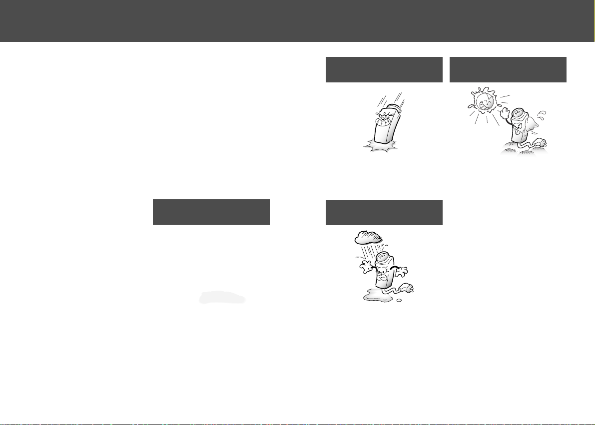
Do not drop the camera or subject
them to physical shocks.
Do not expose the camera to rain or
spill beverage on it.
Do not touch the front lens of the
camera.
Never keep the camera face to strong
light directly.
It can damage the CCD.
It can cause malfunctions to occur.
If it gets wet, wipe it dry immediately.
Liquids can contain minerals that corrode
the electronic components.
Page 6
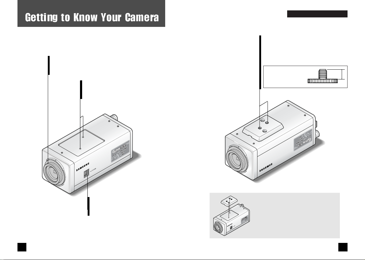
Bottom
www.samsungcctv.com
Tripod Mounting Hole
Used to install the camera on an optional
tripod. The tripod must be equipped with
the screw specified as shown below.
1/4"-20 UNC (20 THREAD)
L:4.5mm±0.2mm (ISO standard),
or 0.197" (ASA standard)
L
GG
EETTTTIINNGG TTOOKKNNOOWWYYOOUURRCCAAMMEERRAA
You can remove and install this bracket
on the top of the camera. You must use
the supplied screw or the equivalent
(within 4mm). If not, the bracket may
not be fixed properly.
Front
C Mount Adapter.
Attach the C-Mount Adapter when using the
C-Mount Lens.
Tripod Mounting Bracket Screw Hole.
Used to fix the Tripod mounting
bracket on the top of the camera.
Auto Iris Lens Connector.
Used to connect the Auto iris
lens plug.
11
COLOR CCD CAMERA
10
COLOR CCD CAMERA
www.samsungcctv.com
Page 7
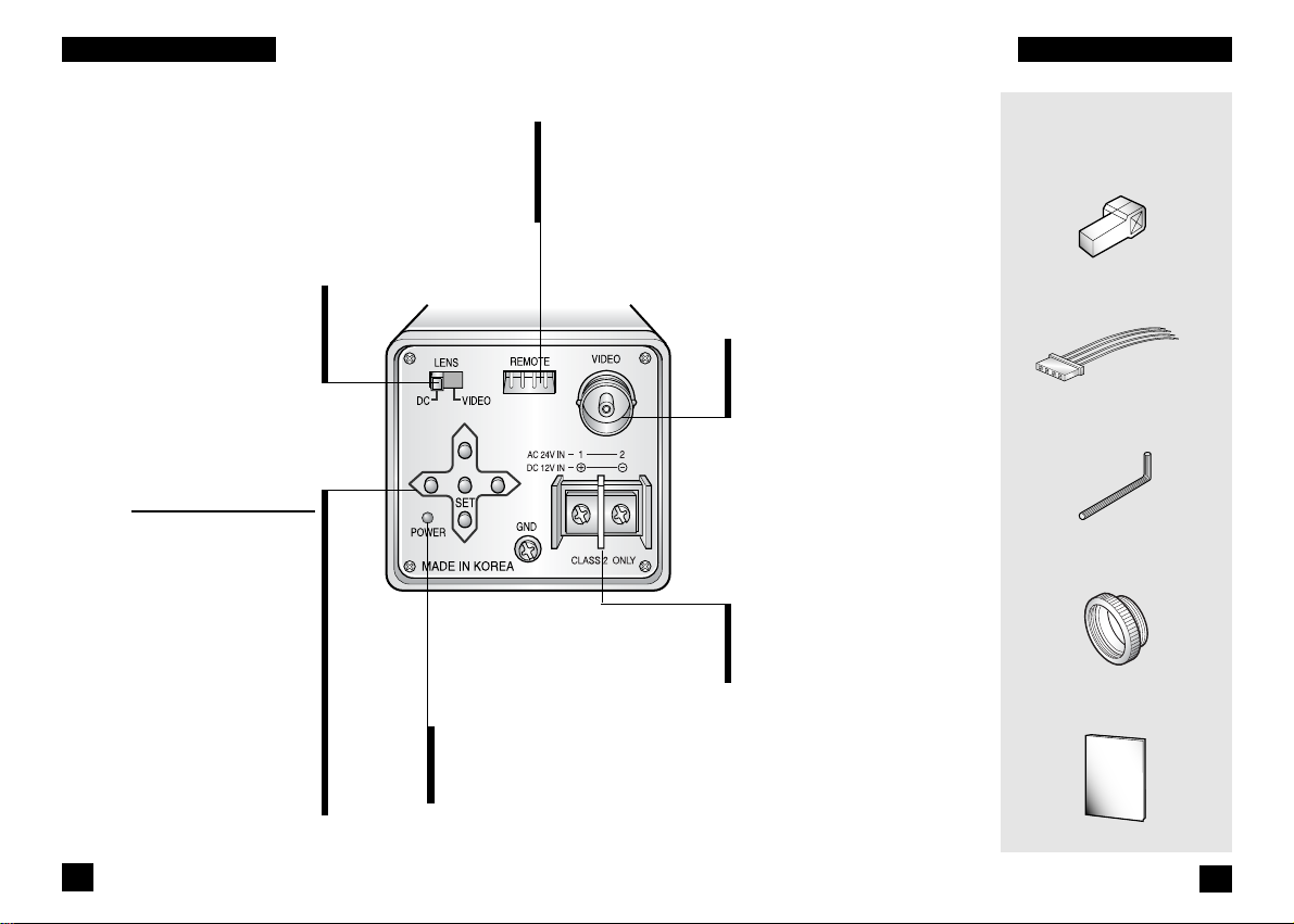
Video Out Jack
Used to connect an external
video monitor in jack.
Power Terminal
Used to connect AC24V or
DC12V power source.
Instruction Manual
Accessories
Auto Iris Lens Plug
Remote Plug
C-Mount Adapter
L-Wrench
Back
Menu Setup Buttons
SET Button
Used to access menu mode.
Also used to confirm the setting.
UP/DOWN Button
Used to choose the desired menu
item. It also moves the cursor
up or down in the menu screen.
LEFT/RIGHT Button
Used to change the parameter of
the selected menu item.
It also moves the cursor to the
left or right in the menu screen.
REMOTE Jack
Used to connect a remote plug.
This jack also provides the
motion detect signal.
DC/VIDEO Selection Switch
Used to choose DC or VIDEO
according to the type of your
auto iris lens.
Power LED
The LED turns on
when power is supplied.
13
COLOR CCD CAMERA
12
COLOR CCD CAMERA
GG
EETTTTIINNGG TTOOKKNNOOWWYYOOUURRCCAAMMEERRAA
GG
EETTTTIINNGG TTOOKKNNOOWWYYOOUURRCCAAMMEERRAA
Page 8

Lens
The lens is not supplied with this camera. Purchase a lens
suitable for your environment. This camera accepts the auto
iris lens and both C- and CS-mount lens.
If the lens is marked with fingerprints or other marks, the image
quality might be poor.
It is recommended to use a high quality lens to improve the
image quality under low illumination.
Installing Auto Iris Lens
1. Peel approximately 8mm from the end of the lens cable outer cover.
2. Peel approximately 2mm from the end of the cable inner cover.
approx. 8 mm
approx. 2 mm
3. Remove the cover from the iris lens plug supplied, and solder the lens
cable to the plug as shown below.
• Video type :
No. 1 Pin --- Red (Power source)
No. 2 Pin --- N.C
No. 3 Pin --- White (Video signal)
No. 4 Pin --- Black (GND)
No. 3 Pin
Cover
No. 1 Pin
connector
Lens cable
No. 4 Pin
No. 2 Pin
CC
OONNNNEECCTTIIOONN
4. Remove the protective cap, and attach the lens to the camera by
turning clockwise.
5. Connect the lens plug to the auto iris connector on the right side of
the camera.
NOTE
Notes
• DC type :
No. 1 Pin --- Damping No. 2 Pin --- Damping +
No. 3 Pin --- Drive +
No. 4 Pin --- Drive -
6. Set the DC/VIDEO selection switch to DC or VIDEO according to the
type of the lens.
14
15
COLOR CCD CAMERA
COLOR CCD CAMERA
Page 9

Mounting a CS-mount lens
After removing the protecting cap, attach the lens into
the camera by turning clockwise.
Mounting a C-mount lens
1. Attach the C Mount lens adapter by turning clockwise.
2. Attach the lens to the camera by turning clockwise.
A heavy lens may disturb the balance with the camera and possibly result in
damage. Don't use a lens heavier than 450g.
It is recommended to set the lens ALC mode to Av mode (Average). Pk mode can
be occurred hunting.
Use the lens under the specification as shown. Otherwise the lens can
damage the camera or abnormal fixing may result.
C-mount lens : 10 mm or less
CS-mount lens : 5 mm or less
NOTE
Page 10

Connecting to Monitor
Connect the VIDEO Out jack to the monitor VIDEO In jack.
Connecting to Power
• As the connecting method varies with the instruments,
refer to the manual supplied with the instrument.
• If necessary, you can connect the monitor to the REMOTE
jack on the back of your camera. For details, see page 39.
• Only connect the cable when the power is turned off.
• Set the 75Ω/Hi-Z selection switch as shown below if you
have an intermediate device.
Page 11

Setup Menu
Camera ID (see page 23)
• ON : Activate. You can enter up to 14
alphanumeric characters and select
the ID position.
• OFF : Deactivate
Backlight (see page 26)
•ON : Backlight Compensation.
•OFF : Deactivate.
Motion Detection (see page 27)
• ON : Activate.
• OFF : Deactivate
Lens Selection (see page 31)
• Manual lens
• DC or Video lens
Shutter Speed Control (see page 32)
• ESC (Electronic Shutter Control ) :
Electronically adjusts the optimal shutter
speed.
•
Manual : Manually adjusts the shutter speed.
CC
OONNFFIIGGUURRAATTIIOONN OOFFMMEENNUU
Gain Control (see page 34)
• AGC (Auto Gain Control) : Activates AGC feature.
• OFF : Deactivate AGC feature.
White Balance Control (see page 35)
• ATW (Auto Tracing White balance) : Automatically
controls white balance.
• AWC (Auto White balance Control) : Automatically
controls white balance.
• Manual : Manually controls white balance.
Color (Day & Night) (see page 36)
• AUTO 1 : Automatic changeover by sensing day or night
condition. (Under sunlight or fluorescent
lamps)
• AUTO 2 : Automatic changeover by sensing day or night
condition. (Under incandescent lamps)
• ON : Activate in only color mode.
• OFF : Activate in only black and white mode.
Synchronization Mode (see page 37)
• INT : Internal synchronization
•LL:External line lock synchronization
Reset (see page 38)
END
20
21
COLOR CCD CAMERA
COLOR CCD CAMERA
Page 12

Use the five Setup Menu buttons on the rear of the camera.
1. Press the SET button to access the setup mode.
Setup menu is displayed on the monitor screen.
LEFT button
UP button
SET button
RIGHT button
DOWN button
Setup
Camera ID OFF
Backlight OFF
Motion Detect. OFF
Lens DC
Shutter ESC
Gain AGC
White Balance ATW
Color Auto1
Sync. INT
Reset
End
Setup
Camera ID OFF
Backlight OFF
Motion Detect. OFF
Lens DC
Shutter ESC
Gain AGC
White Balance ATW
Color Auto1
Sync. INT
Reset
End
Setup
Camera ID OFF
Backlight OFF
Motion Detect. OFF
Lens DC
Shutter ESC
Gain AGC
White Balance ATW
Color Auto1
Sync. INT
Reset
End
SS
EETTUUPPMMEENNUU
2. Select the desired feature using the UP or DOWN button.
Each time you press the UP or DOWN button, the
arrow indicator moves up or down.
Move the arrow indicator to the desired feature item.
3. Change the status of the selected feature using the LEFT or RIGHT button.
4. When completed, move the arrow indicator to 'End' and press the SET button.
Camera ID
If you enter a camera ID, the name will be displayed in the screen monitor.
1. Press the SET button to display the setup menu and move the arrow indicator to
'Camera ID' using the UP or DOWN button.
2. Set 'Camera ID' to 'ON' using the LEFT or RIGHT button.
Select the function
using the UP or
DOWN button.
Change the status
using the LEFT or
RIGHT button.
If the camera ID feature is set to 'OFF', the name will not displayed
in the monitor.
NOTE
Notes
22
23
COLOR CCD CAMERA
COLOR CCD CAMERA
Page 13

3. Press SET button.
The ID generation screen appears.
4. The alphanumeric letters are displayed.
You can enter up to 14 characters.
Move the cursor to the desired character by using the 4directional buttons. The selected character blinks and
appears in the bottom of the screen.
Press the SET button to confirm the blinking character. The
first character is saved and the cursor in the bottom of the
screen moves to the next position.
Repeats steps and until you create the full name you
want.
ID Generation
ABCDEF GHIJKLM
NOPQRSTUVWXYZ
abcdefghijklm
nopqrstuvwxyz
-. 0123456789
Clr Pos End
F __________
If you make a mistake while entering name
<To Erase All>
Move the cursor to 'Clr' in the ID generation screen and press the SET button to erase the ID name.
<To Edit existing Camera ID>
Move the cursor to
or in the ID generation screen, and press SET button. After you choose
or , each time you press the SET button, the cursor moves to the left or right in the string of
characters. When the cursor moves to the wrong character, correct the character by using the 4directional buttons.
5. Select the position at which the camera ID will be located on the screen.
Move the cursor to 'Pos' and press SET button.
The camera ID is displayed on the top left of the monitor
screen. (Default position)
Select the position by using the 4-directional buttons, then
press the SET button to confirm the position.
6. When completed, move the cursor to 'End' and press SET button.
Page 14

Motion Detection
Your camera transmits an alert signal when it detects
motion of an object on the screen. If you connect the camera
to an external alarm, you can pay attention to the screen
when the alarm sounds. This feature is useful when you
have to monitor several screens simultaneously.
Backlight
1. Press the SET button to display the setup menu and move the arrow
indicator to 'Motion Detect.' using the UP or DOWN button.
2. If you want to activate the motion detecting mode, set 'Motion
Detect.' to 'ON' using the LEFT or RIGHT button.
The Wide Dynamic Range and Super BLC technology in
your camera provides intelligent light level control to
overcome the severe Backlight conditions.
1. Press the SET button to display the setup menu and move the arrow
indicator to ‘Backlight’ using the UP or DOWN button.
2. Set ‘Backlight’ to “ON/OFF” using the LEFT or RIGHT button.
• ON : Backlight Compensation.
The activating zone of BLC is focused on the center of
monitor occupying 20% of the full screen.
BLC area can be focused on more by increasing the weight
number.
• OFF : Deactivate.
3. Press the ‘SET’ button.
When ‘ON’ is choosen, you can adjust the weight.
You can select the weight from 0 to 4.
By increasing the number, the activating zone of BLC is more focused on the center of monitor.
4. When completed, press the SET button.
Setup
Camera ID OFF
Backlight OFF
Motion Detect. OFF
Lens DC
Set weight
Weight 2
Press SET to Return
Setup
Camera ID OFF
Backlight OFF
Motion Detect. OFF
Lens DC
Shutter ESC
3. Press the SET button.
The Motion Detection screen appears. You can assign the
active zone.
26 27
COLOR CCD CAMERA COLOR CCD CAMERA
SS
EETTUUPPMMEENNUU
SS
EETTUUPPMMEENNUU
Page 15

4. Specify the zone area.
You can point to the top, bottom, left, and right base lines by
setting a proper value from 0 to 15 with an increment of 1.
Move the arrow indicator to 'Top' using the UP or DOWN
button and increase or decrease the value using the LEFT or
RIGHT button. Repeat the procedure for bottom, left, and
right.
Top base line
Right base line
Bottom base line
Left base line
5. Adjust Sensitivity.
Move the arrow indicator to 'Sensitivity' using the UP or
DOWN button, then press the LEFT or RIGHT button to
decrease or increase the value.
If you decrease the sensitivity, the camera will detect only
motion that is clearly noticeable. If you want to set the
camera to detect minor motion, increase the sensitivity.
You can select the sensitivity from 0 to 10.
Higher sensitivity detects smaller motions at the risk of false
detection.
Therefore zone adjustment is recommended rather than
sensitivity adjustment.
How to Assign the Zone
If you assign a zone, an alert signal occurs when the camera detects
motion of objects in that zone.
Motion Detection
Top 4
Bottom 12
Left 3
Right 7
Sensitivity
5
Press SET to Return.
Ex. Zone
Top 2 Bottom 12 Left 0 Right 7
Ex. Full screen
28 29
COLOR CCD CAMERA COLOR CCD CAMERA
SS
EETTUUPPMMEENNUU
SS
EETTUUPPMMEENNUU
Page 16

6. When completed, move the arrow indicator to 'End' and press the SET
button.
Tips on Using the Motion Detection Feature
• After selecting zone and sensitivity, perform a test operation to make sure
it works properly.
• If the lighting flickers, the motion detection feature might not work
properly.
• The object should occupy 10% or more of its zone. The bigger the object,
the higher sensitivity.
• If the brightness of an object changes rapidly by sudden lighting change,
the camera may detect it as a motion.
• When this feature is activated, another algorithm may take more time to
be operated.
• This system does not guarantee prevention of fires or thefts. The
manufacturer is not responsible for any accident or damage.
• You can use the REMOTE jack on the rear of the camera to connect an
external alarm device. For details, see page 39.
Lens Selection
You can set the type of the lens, and control the brightness
of the screen.
1. Press the SET button to display the setup menu and move the arrow
indicator to 'Lens' using the UP or DOWN button.
2. Select the lens type using the LEFT or RIGHT button.
You can select from Manual, Video or DC lens.
Hint
When the auto iris lens is mounted, you have to set the DC/VIDEO
selection switch on the rear of the camera properly according to the
type of the lens. The setup window displays DC or VIDEO according
to status of this selection switch.
Page 17

4. When completed, press the SET button.
3. If you choose “DC”, you can adjust the brightness.
After pressing the SET button, adjust the brightness of the monitor
screen using the LEFT or RIGHT button.
The screen becomes darker when the value is decreased and
brighter when the value is increased.
You can adjust the brightness from 0 to 99.
Shutter Speed Control
Select ESC (Electronic shutter control) or manual control of
the shutter speed.
1. Press the SET button to display the setup menu and move the arrow
indicator to 'Shutter' using the UP or DOWN button.
2. Select 'ESC' or 'Manual' shutter using the LEFT or RIGHT button
.
ESC : Electronically controls the optimal shutter speed.
Manual : You can select the shutter speed.
3. If you choose 'Manual', select the optimal shutter speed.
You can select speed from '1/60' to '1/10,000' sec (NTSC
Models), / '1/50' to '1/10,000' sec (PAL Models).
When the shutter speed is increased or decreased using the
LEFT or RIGHT button, you can find the difference by
monitoring the brightness of the screen.
4. When completed, press the SET button.
Set Shutter
Shutter 1/50
Set Shutter
Shutter 1/60
If the camera directly faces strong fluorescent light in 'ESC' mode,
the image may become unstable.
If you choose ‘ESC’., you can adjust the brightness of monitor
screen using the LEFT or RIGHT button.
NOTE
Notes
You can only adjust the brightness in DC mode.
It is recommended to set the value at 60 to stabilize the operation.
To control the brightness of the auto iris lens, refer to the owner's
manual.
NOTE
Notes
Setup
Camera ID OFF
Backlight OFF
Motion Detect. OFF
Lens DC
Shutter ESC
Gain AGC
White Balance ATW
NTSC Models
PAL Models
32
33
COLOR CCD CAMERA
COLOR CCD CAMERA
SS
EETTUUPPMMEENNUU
SS
EETTUUPPMMEENNUU
Page 18

Gain Control
1. Press the SET button to display the setup menu and move the arrow
indicator to 'Gain' using the UP or DOWN button.
2. Select 'AGC' or 'OFF' using the LEFT or RIGHT button.
AGC : Activates automatic gain control feature.
OFF : Deactivates automatic gain control feature.
If you choose ‘AGC’, you can adjust the brightness using the LEFT or
RIGHT button from 0 to 99.
In ‘AGC’ mode, you can select the Gain limit ‘Low’ or ‘High’ or ‘Middle’.
If you choose ‘High’ in the- ‘Gain limit’ menu, the image is more
detailed and more noise.
If you choose ‘Low’ in the ‘Gain limit’ menu, the image is less detailed
and less noise.
NOTE
Notes
Do not use 'ATW' mode when the camera is installed under severe
lighting condition.
NOTE
Notes
White Balance Control
Your camera provides 3 white balance control modes. You
can select the most suitable one. You can adjust the white
balance.
1. Press the SET button to display the setup menu and move the arrow
indicator to 'White Balance' using the UP or DOWN button.
2. Select the desired control mode using the LEFT or RIGHT button.
The three white balance control modes are as follows :
• ATW (Auto Tracing white balance ) : The camera
automatically controls the white balance in any environment.
• AWC (Auto White balance Control) : The white balance is
automatically adjusted in a specific environment. In order to
obtain the best result, press the SET button while the camera
focuses on white paper. If the environment including the light
source is changed, you have to adjust the white balance again.
• Manual : To fine adjust, select the Manual mode. You can
increase or decrease the red or blue factor while monitoring the
difference on the screen. To use the mode more effectively, set it
to ATW or AWC mode to obtain a proper white balance, then set
to 'Manual' mode and press the SET button. Increase or decrease
the value for red and blue, watching the color of the picture, and
press the SET button when you obtain the best color.
Setup
Camera ID OFF
Backlight OFF
Motion Detect. OFF
Lens DC
Shutter ESC
Gain AGC
White Balance ATW
Page 19

Synchronization Mode
Two synchronization modes are available Internal and
External linelock. -In linelock mode, it synchronizes the video
signal between cameras without a synchronous generator.
The linelock synchronization is only used in the areas of
60Hz(NTSC Models)/50Hz(PAL Models).
1. Press the SET button to display the setup menu and move the arrow
indicator to 'Sync.' using the UP or DOWN button.
2. Select 'LL' or 'INT' using the LEFT or RIGHT button.
INT : Internal synchronization.
LL : External linelock synchronization.
Color ( Day & Night)
Your camera provides automatic mode changeover by sensing day
or night conditions. It changes to Color mode in day conditions for
optimal color and to BW mode in night conditions for clear
identification.
1. Press the SET button to display the setup menu and move the arrow
indicator to 'Color' using the UP or DOWN button.
2. Select a mode using the LEFT or RIGHT button.
ON : Color mode is kept up.
OFF : A black and white mode is kept up.
Auto1 : Select this mode under a normal light source(sunlight or
fluorescent lamp). When changing between color and
B/W, the OSD key does not act for 3 seconds.
Auto2 : Select this mode under light source that have a wavelength
range mostly above 800nm(incandescent lamp). When
changing between color and B/W, the OSD key does not
act for 3 seconds.
3. L.L mode Press the SET button.
3. Press the SET button.
Setup
Camera ID OFF
Backlight OFF
Motion Detect. OFF
Lens DC
Shutter ESC
Gain AGC
White Balance ATW
Color Auto1
Sync. LL
Reset
End
Setup
Camera ID OFF
Backlight OFF
Motion Detect. OFF
Lens DC
Shutter ESC
Gain AGC
White Balance ATW
Color Auto1
Sync. LL
If you set low level in Video IRIS mode, Color/BW may not change over
automatically.
Under Gain OFF Color/BW does not change over automatically, ON/OFF is
only available.
If you change ‘Gain’ menu from ON to OFF, ‘Color’ mode change to ON.
If you change ‘Gain’ menu from OFF to ON, ‘Color’ mode change to Auto1.
Select Auto2 in ‘Color’ mode under incandescent lamp.
Adjust the focus if the camera is out of focus for changing modes.
NOTE
Notes
36
37
COLOR CCD CAMERA
COLOR CCD CAMERA
SS
EETTUUPPMMEENNUU
SS
EETTUUPPMMEENNUU
Page 20

If you connect a remote plug to the REMOTE jack on the
rear of the camera as shown below, you can access the
menu setup mode from a remote place.
You must turn the camera power off when you connect or remove
the remote plug.
NOTE
NOTE
The phase is preset to 225 degrees at the factory. You can re-
adjust it from 0 to 270 degrees.
When the power frequency is 50Hz, you can not use linelock
mode(NTSC Models).
When the power frequency is 60Hz, you can not use the linelock
mode(PAL Models).
’Sync.’ mode is fixed to ‘INT’ in DC12V input power.
NOTE
Notes
This function resets the camera to the default settings preset at the factory.
All modes are initialized and return to the default status.
Reset
Tx (Transmit Data)
GND
Rx (Receive Data)
MD (Motion Detection Signal)
Setup
Camera ID OFF
Backlight OFF
Motion Detect. OFF
Lens DC
Shutter ESC
Gain AGC
White Balance ATW
Color Auto1
Sync. INT
Reset
End
Line Lock
Phase
225
Press SET to Return
38 39
COLOR CCD CAMERA COLOR CCD CAMERA
SS
EETTUUPPMMEENNUU
2.5 0.5sec
+4.0V~+5.0V
0V
1. RS-232C Communication Setting.
Mode : Serial
Bit/sec : 9600bps
Port : Com1
Parity : None
2. Setup menu Command.
Setup menu Command Byte
Set A0, A0, 01, 00, 00, AF 6
Up A0, A0, 02, 00, 00, AF 6
Down A0, A0, 03, 00, 00, AF 6
Left A0, A0, 04, 00, 00, AF 6
Right A0, A0, 05, 00, 00, AF 6
3. Motion Detection Output Signal Level.
There is motion
There is no motion
Page 21

If you have trouble operating your camera, refer to the
following table. If the guidelines do not enable you to solve
the problem, contact an authorized technician.
Problem
Nothing appears on
the screen.
The image on the
screen is dark.
The afterimage of
moving objects
remain on the
screen.
The image on the
screen is dim.
The camera is not
working properly,
and the surface of the
camera case is hot.
Solution
• Check that the power cord and line connection
between the camera and monitor are fixed properly.
• Check that the DC/VIDEO selection switch on the
rear of the camera is set to a proper position
according to the type of your auto iris lens.
• Check that you have set the 'Shutter' feature under
the setup menu to 'ESC' mode.
• Check that you have set to a proper sensitivity
and brightness level in the 'Shutter' feature.
• It occurs temporarily when the camera converge
available light to produce clear image under low
illumination. It is normal.
• If you decrease the sensitivity level of the 'Shutter'
feature under the setup menu, this symptom can be
eliminated, but the image on the screen may be
darker.
• Check if the lens is stained. If dirty, clean the lens
with soft, clean cloth.
• Check that you have properly connected the camera
to an appropriate power source. Refer to page 17.
TT
RROOUUBBLLEESSHHOOOOTTIINNGG
Problem
‘Auto’ mode does
not activate.
The color of the
picture is not
matched.
The image on the
screen flickers.
Solution
•Have you set the 'Gain’ feature under the setup
menu to 'OFF'? Set the feature to 'AGC'.
•Have you set the level of video lens too low?
• Check that you have properly set the 'White
Balance’ feature under the setup menu.
• Is the camera facing to direct sunlight or
fluorescent lighting? Change the camera position.
• Check that the DC/VIDEO selection switch on the
rear of the camera is set to a proper position
according to the type of your auto iris lens.
The contrast on the
screen is too weak.
• Adjust the contrast feature of the monitor.
• If the camera is exposed to too strong light,
change the camera position.
The image on the
screen is distorted.
• Check that the power frequency is proper in
'Sync.’ If the power frequency is not proper, the
linelock synchronization mode cannot be used.
Set the 'Synchronization Mode' to 'INT' mode.
– NTSC Model’s Power frequency in LL mode : 60Hz
– PAL Model’s Power frequency in LL mode : 50Hz
40
41
COLOR CCD CAMERA
COLOR CCD CAMERA
Page 22

DECLARA TION OF CONFORMITY
Application of Council Directive(s) 89/336/EEC
Manufacturer's Name SAMSUNG TECHWIN CO., LTD
Manufacturer's Address SAMSUNG TECHWIN CO., LTD
42, SUNGJU-DONG CHANGWON-CITY,
KYUNGNAM, KOREA, 641-120
European Representative Name
European Representative Address
Equipment Type/Environment CCTV Camera
Model Name SDN-520P/510P
Beginning Serial NO. S2040001
Year of Manufacture 2002. 4. 1
Conformance to EN 50081-1 : 1992
EMC-Directive 89/336 EEC and 92/31/EEC
EN 50130-4 : 1996
We, the undersigned, hereby declare that the equipment specified above conforms to the
above Directive(s).
Manufacturer SAMSUNG TECHWIN CO., LTD Legal Representative in Europe
Signature Signature
Full Name YOUNG TAEK SON Full Name
Position QUALITY CONTROL MANAGER Position
Place CHANGWON, KOREA Place
Date 2002. 4. 1 Date
Power Source
Image Pick-Up Device
Scanning System
Picture elements
Effective picture elements
Resolution
Video Output
Backlight Compensation
Color
RS-232C Communication
O.S.D
Iris Mode
Electronic Shutter
White Balance
Lens Mount
Min. Illumination
S/N Ratio
Power Consumption
Synchronizing System
Environmental conditions
Dimension
Weight
Accessory
811(H) 508(V)
768(H)
494(V)
795(H)
596(V)
752(H) 582(V)
1/3 SONY
EX-VIEW HAD
IT CCD
1/3
SONY
EX-VIEW HAD
IT CCD
1/3 Solid State
Image Device
CCD(SONY)
1/3
Solid State
Image Device
CCD(SONY)
480(Color)/520(BW)TV Lines Horizontally
1.0 Vp-p NTSC composite 1.0 Vp-p PAL composite
On/Off Selectable
Auto1/Auto2/On/Off Selectable
Available
Built-in
Video Iris / DC Iris / ESC Selectable
1/60~1/10,000 sec 1/50~1/10,000 sec
ATW / AWC / MANUAL Selectable
CS-mount(or C-mount with the supplied adaptor)
More than 48dB (AGC Off)
3.8Wat AC24 / 3.5W at DC12
Internal/Line lock selectable
10 C~+50 C
55(W) 57(H) 135(L)mm (Without Lens)
Approx 400g (Without Lens)
Auto Iris Lens Plug, Remote Plug, L-Wrench,
Instruduction Manual, C-Mount Adapter
2:1 Interlace(NTSC Standard)
525 Lines / 60 Fields / 30 Frames
2:1 Interlace(PAL Standard)
625 Lines / 50 Fields / 25 Frames
Item
AC 24V, 60Hz / DC 12V
AC 24V, 50Hz / DC 12V
42
COLOR CCD CAMERA
43
COLOR CCD CAMERA
0.5 Lux at F1.2 (Color)
0.01 Lux at F1.2 (B&W)
0.5 Lux at F1.2 (Color)
0.01 Lux at F1.2 (B&W)
0.5 Lux at F1.2 (Color)
0.03 Lux at F1.2 (B&W)
0.5 Lux at F1.2 (Color)
0.03 Lux at F1.2 (B&W)
 Loading...