

Page 1
Temperature Regulator Series 43
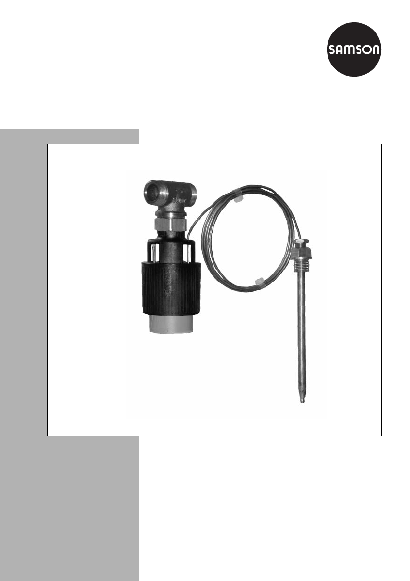
Type 43-2 N
Fig. 1 ⋅Type 4 3-2 N
Mounting and
operating instructions
EB 2186 EN
Edition July 2001
Page 2
Design and principle of operation
1. Design and principle of operation
1.1 Temperature regulator
The temperature regulator consists of the
valve and the Type 2430 K Thermostat
which are screwed together.
The valve comprises the valve body, seat
and plug, the thermostat comprises operating bellows, set point spring, capillary tube
and temperature sensor.
1.2 Version with double adapter
and/or manual adjuster
For measurement of an additional process
variable, the temperature regulator can be
equipped with a double adapter plus an addi-
The device may only be assembled, started up and operated by trained and
experienced personnel familiar with this product.
According to these mounting and operating instructions, trained personnel is
referred to as individuals who are able to judge the work they are assigned to
and recognize possible dangers due to their specialized training, their knowledge and experience as well as their knowledge of the applicable standards.
Any hazards which could be caused by the process medium, the signal press-
ure and moving parts of the control valve are to be prevented by means of appropriate measures.
In addition, it is necessary to make sure that the control valve is only used in
areas where the operating pressure and temperatures do not exceed the operating values which are based on the valve sizing data submitted in the order.
Proper shipping and appropriate storage are assumed.
tional thermostat, or with a manual adjuster.
For further details, refer to EB 2176 EN.
Principle of operation:
The temperature regulator works according
to the adsorption principle. The temperature
of the process medium produces a pressure
in the sensor, which is proportional to the
actual value. This pressure is transmitted via
the capillary tube (10) to the operating element (13) and converted into a positioning
force.
This force acts upon the operating bellows
(9) and the operating element pin (12) and
is passed on to the plug stem and plug (3).
Turning the set point adjuster (8) changes
the regulators point of response via the
spring (7). As a result, the valve plug passes
through its travel range within a higher or
2
EB 2186 EN
Page 3
lower temperature range sensed by the sensor.
For thermostats working according to
Note:
the vapor pressure principle, refer to
EB 2430-3 EN.
Design and principle of operation
1.1
1
2
3
4
5
15
(20Nm)
7
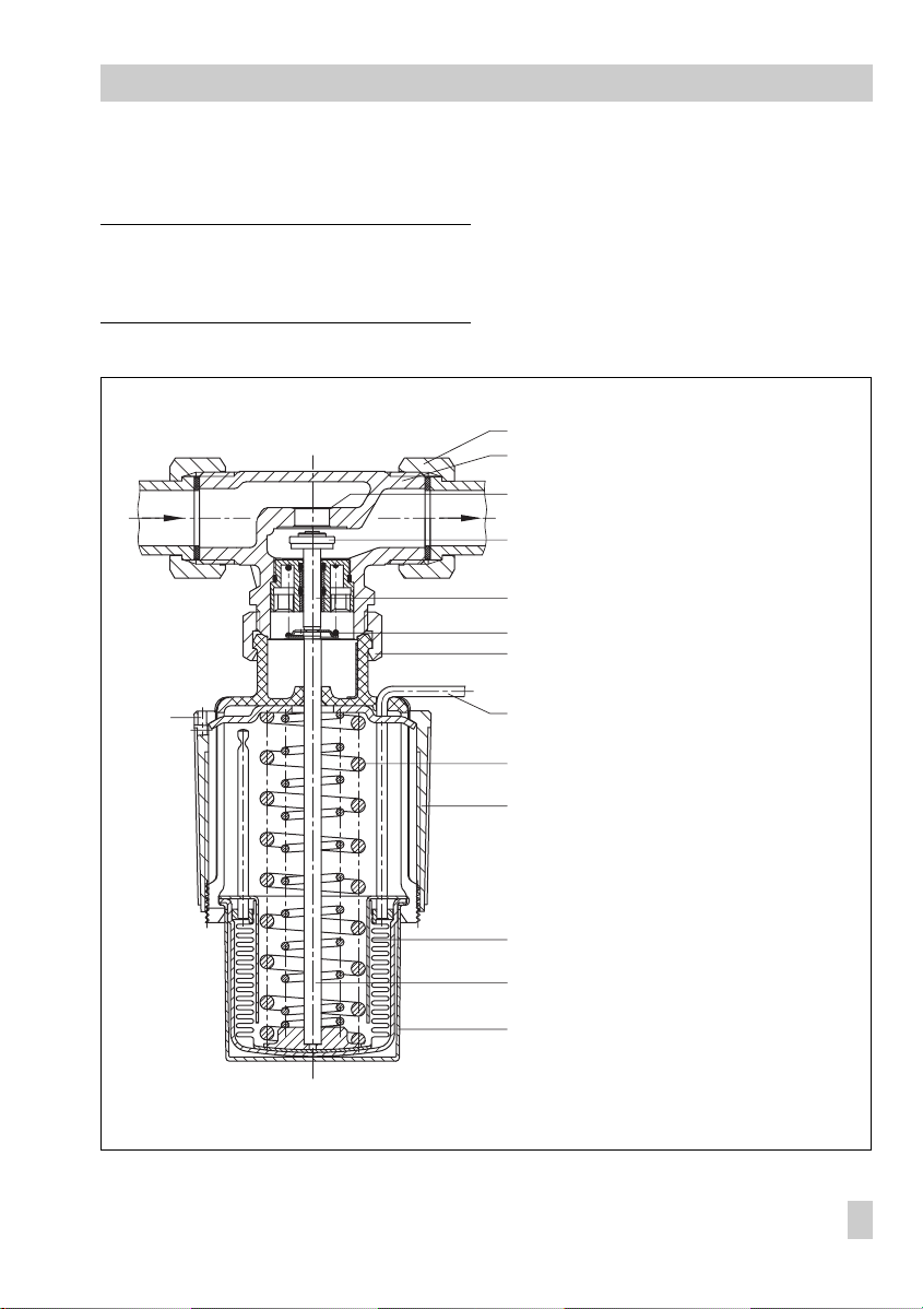
Fig. 2 ⋅Sectional drawing
10
7
8
9
12
13
1 Valve body
1.1 Coupling nut with gasket and
accessory weld-on fittings
(must be ordered separately)
2Seat
3Plug
4Plug stem
5Valve spring
7Set point spring
8 Set point adjuster
9 Operating bellows
10 Capillary tube
12 Pin of operating element
13 Operating element
14 Lead bore
15 Coupling nut
EB 2186 EN
3
Page 4

Installation
2. Installation
On installing the regulator, make sure that
the permissible ambient temperature does
not exceed 80 °C.
2.1 Installing the valve
The valve may be installed in any desired
position, however, we recommend that the
valve be installed in a horizontal pipeline
with the thermostat vertically suspended.
The medium must flow through the valve in
direction indicated by the arrow on the
valve body.
2.1.1 Strainer
A strainer (SAMSON Type 1 NI) must be installed upstream of the relevant valve, since
sealing particles, globules or other impurities carried along by the process medium could impair the proper functioning of
the valve, especially tight shut-off.
The filter element must be vertically suspended.
Ensure that ample space is available to
remove the filter.
2.1.2 Additional installation instructions
Ideally, hand-operated shut-off valves
should be installed both upstream of the
strainer and downstream of the regulator.
This allows the plant to be shut down for
cleaning and maintenance routines, or
when the plant is not operated for extended
periods.
To check the adjusted set point, we recommed that a thermometer be installed
near the sensor immersed in the medium to
be controlled.
2.2 Installing the temperature sensor
The temperature sensor may be installed in
any desired position. Its entire length must
be immersed in the medium to be controlled.
When choosing the point of installation,
make sure that the sensor is installed in a lo-
1123 54
Fig. 3 ⋅Installation example in a water-heated boiler
4
EB 2186 EN
1Shut-off valves
2Strainer
3Regulator
4 Thermometer
5 Temperature sensor
Page 5

Adjusting the set point
cation where overheating and considerable
idling times do not occur.
A welding socket with a G 1/2 female
thread connection should be welded where
the sensor is to be installed.
Seal the screw gland or thermowell into
the welding socket.
Insert the sensor and tighten it with the
clamping screw.
CAUTION!
To prevent damage caused by corrosion, it
is important to make sure on installing the
sensor or thermowell that only the same
kind of materials are used together. For example, do not use a sensor or thermowell
made of non-ferrous metal in a stainless
steel heat exchanger. In this case, the sensor should be used together with a stainless
steel thermowell.
2.2.1 Capillary tube
The capillary tube should be routed without
bends or twists. The smallest bending radius
is 50 mm. Roll up any extra length to form
a ring. Do not bend or shorten.
The ambient temperature around the tube
should be kept as even as possible.
3. Operation
3.1 Adjusting the set point
To adjust the set point value, use the black
plastic ring (set point adjuster 8) while watching the reference thermometer.
The adjustment diagrams below can be used
as a guide to find the first approximate value.
The adjustment is infinitely variable. Turning
the ring clockwise reduces the temperature
and counterclockwise turning increases it.
The temperature can be fixed at an adjusted
value by lead-sealing the bore (14) in the set
point adjuster.
Set point
range °C
0 to 35 2.5 9.5
25 to 70 3 9.5
40 to 100 4 9.5
100
80
C
˚
Set point change
per turn
Sensor
diameter
40...100
60
40
20
0
01234
Turns of adjuster (scale marking)
Fig. 4 ⋅Set point adjustment
25...70
0...35
EB 2186 EN
5
Page 6

Adjusting the set point
4. Troubleshooting
Should the temperature exceed the set point
adjusted, the cause could be either contamination of seat and plug or wear and tear of
the seat and plug no longer ensuring tight
shut-off.
For remedy, the valve can be disassembled
after shutting down the plant.
5. Customer inquiries
Should you have any inquiries regarding
the temperature regulator, please submit the
following details:
(see also nameplate)
Type and nominal size
Order no. and product no.
Upstream and downstream pressure
Type of process medium and temperature
Max. and min. flow rate
Has a strainer been installed?
Installation drawing
6
EB 2186 EN
Page 7

6. Dimensions in mm
Dimensions in mm
65
G½
ISO 228/1 - G¾B
150
Ver si on wi th thr ea de d e nd s
129
SW30
65
Version with weld-on fittings
with thermowell or with screw gland
210
Bulb sensor
G½
185
Ø12 Ø9.5
Soldered ends
107 for ∅di =15, 103 for ∅di =18
di
Ø21.3
SW30
185
Ø21.3
SW30
EB 2186 EN
7
Page 8

SAMSON AG ⋅ MESS- UND REGELTECHNIK
Wei smü lle rst raß e 3 ⋅ D-60314 Frankfurt am Main
Telefon (0 69) 4 00 90 ⋅ Telefax (0 69) 4 00 95 07
Internet: http://www.samson.de
EB 2186 EN
S/C 2001-07
 Loading...