

Page 1
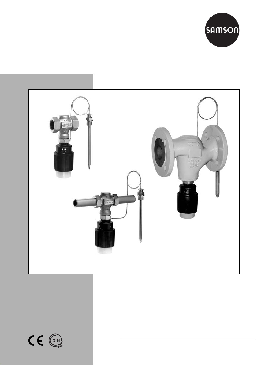
Temperature Regulators Series 43
Type 43-1
Type 43-2
Type 43-1 ⋅ Ver sio n w ith
female thread
Temperature regulator versions
Fig. 1
⋅
Type 43-2 ⋅ Ver si on wi th fl ang ed va lv e b od y
DN 32 to 50
Ty pe 4 3- 2 ⋅ Version with
weld-on fittings
Mounting and
operating instructions
EB 2171 EN
Edition August 2003
Page 2

Contents
Contents Page
1. Design and principle of operation
. . . . . . . . . . . . . . . . . . . . . .
1.1 Temperature regulator . . . . . . . . . . . . . . . . . . . . . . . . . . . . 4
1.2 Version with safety thermostat . . . . . . . . . . . . . . . . . . . . . . . . 4
1.3 Version with double adapter and/or manual adustment . . . . . . . . . . . . 4
2. Installation
. . . . . . . . . . . . . . . . . . . . . . . . . . . . . . . . . 6
2.1 Installing the valve . . . . . . . . . . . . . . . . . . . . . . . . . . . . . . 6
2.1.1 Strainer . . . . . . . . . . . . . . . . . . . . . . . . . . . . . . . . . . . 6
2.1.2 Additional installation instructions . . . . . . . . . . . . . . . . . . . . . . 6
2.2 Installing the temperature sensor . . . . . . . . . . . . . . . . . . . . . . . 6
2.2.1 Capillary tube . . . . . . . . . . . . . . . . . . . . . . . . . . . . . . . . 7
3. Operation
. . . . . . . . . . . . . . . . . . . . . . . . . . . . . . . . . . 7
3.1 Set point adjustment . . . . . . . . . . . . . . . . . . . . . . . . . . . . . 7
4. Maintenance Replacing parts
. . . . . . . . . . . . . . . . . . . . . . . 8
4.1 Cleaning or replacing the plug . . . . . . . . . . . . . . . . . . . . . . . . 8
5. Troubleshooting
6. Dimensions in mm and weights
7. Customer inquiries
. . . . . . . . . . . . . . . . . . . . . . . . . . . . . . . 9
. . . . . . . . . . . . . . . . . . . . . . . 10
. . . . . . . . . . . . . . . . . . . . . . . . . . . . . . 11
4
2
Typetesting
The Type 43-1 and Type 43-2 Temperature Regulators are typetested accord ing to DIN 3440 by the German technical surveillance association TÜV.
Register number available on request
EB 2171 EN
Page 3
Safety instructions
General safety instructions
The temperature regulators may only be mounted, started up or serviced by
fully trained and qualified personnel, observing the accepted industry codes
and practices. Make sure employees or third persons are not exposed to any
danger.
All safety instructions and warnings in these mounting and operating instruc tions, particularly those concerning assembly, start-up and maintenance, must
be observed.
The control valves fulfil the requirements of the European Pressure Equipment
Directive 97/23/EC. Valves with a CE marking have a declaration of con formity which includes information about the applied conformity assessment
procedure. The declaration can be viewed and downloaded on the Internet at
http://www.samson.de.
For appropriate operation, make sure that the temperature regulators are
only used in areas where the operating pressure and temperatures do not ex ceed the operating values which are based on the valve sizing data submitted
in the order. The manufacturer does not assume any responsibility for dam age caused by external forces or any other external influence!
Any hazards which could be caused in the temperature regulator by the pro cess medium, the operating pressure or by moving parts are to be prevented
by means of the appropriate measures.
Proper shipping and appropriate storage are assumed.
Caution!
Do not start up the temperature regulators before the valve and control
thermostat have been installed.
Prior to removing the regulator from the pipeline, make sure the relevant sec -
tion of the pipeline is depressurized and drained.
Allow the plant to fill up slowly on start-up.
Make sure regulators are frost protected when used to control freezing media.
If the sensor is used in combination with a thermowell, only SAMSON thermo-
wells should be used.
EB 2171 EN
3
Page 4

Design and principle of operation
1. Design and principle of operation
1.1 Temperature regulator
The temperature regulators consist of a
valve with the Type 2430 K Thermostat
screwed onto it.
The valve consists of a valve body, seat and
a pressure-balanced plug. The thermostat
contains a positioning bellows, set point
spring, capillary tube and temperature sensor.
1.2 Version with safety thermostat
When a Type 2439 K/ 2403 K Safety
Thermostat is attached to the valve or regulator, these versions are used as safety temperature limiters STL or safety temperature
monitors STM.
Refer to the mounting and operating instructions EB 2185 EN for more details.
1.3 Version with double adapter
and/or manual adjustment
The temperature regulator can be equipped
with a double adapter and/or manual adjustment to control a further control variable.
Refer to the mounting and operating instructions EB 2176 EN for more details.
Principle of operation:
The temperature regulator functions according to the adsorption principle. The tempera ture of the medium to be controlled creates
a pressure in the sensor which corresponds
with the temperature measured. This press ure is transferred over the capillary tube
(10) to the operating element (13) where it
is converted into a positioning force.
The force acts over the positioning bellows
(9) and pin of the operating element (12)
on the plug stem and plug (3).
By turning the set point adjuster (8), the
point of response over the spring (7) is
changed. As a result, the valve plug moves
through its full travel range within a higher
or lower temperature range measured by
the sensor.
Note:
Thermostats that function according to the
vapor pressure principle are described in
EB 2430-3 EN.
4
EB 2171 EN
Page 5
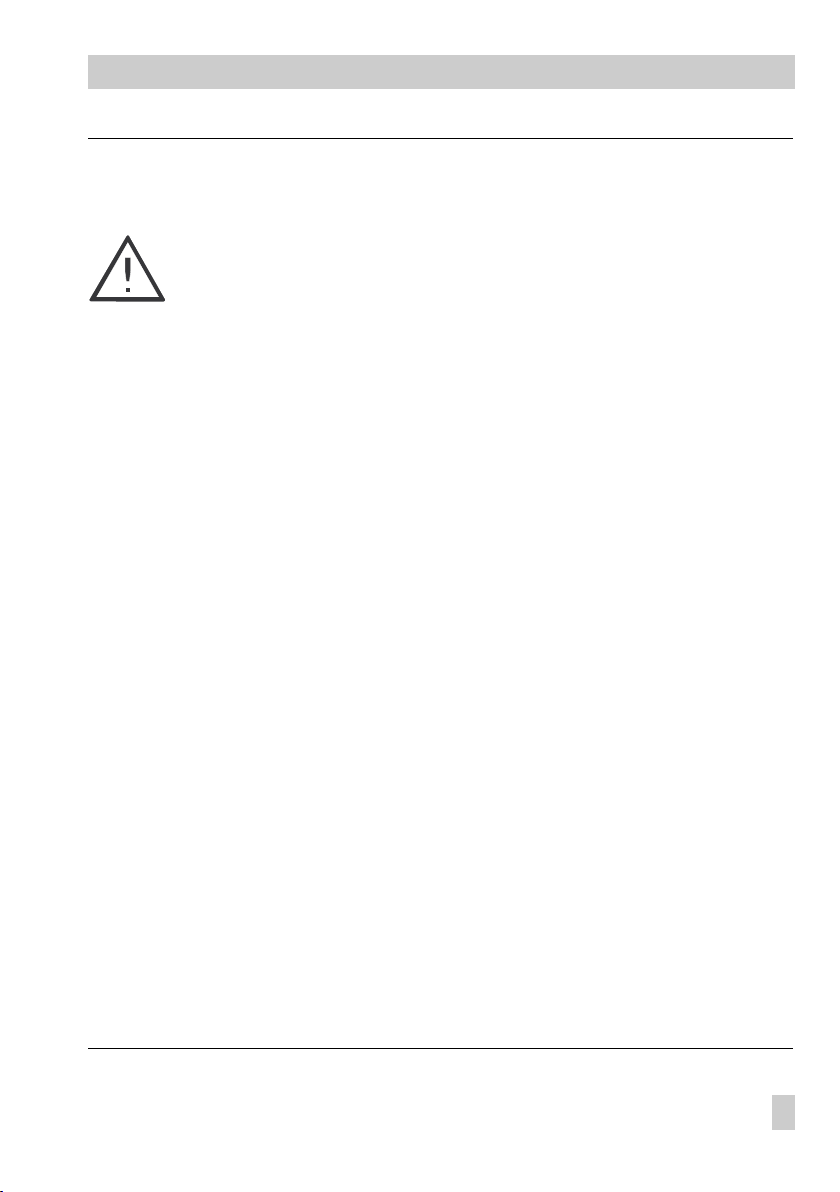
Design and principle of operation
Type 43-2
Type 2432 K Valve
1.1
15
(20 Nm)
14
Type 2439 K Thermostat
Type 43-1
Type 2431 K Valve (female thread)
1
2
3
4
5
3
10
7
8
9
12
13
1Valve body
1.1 Connection nut with
gasket and weld-on
fitting
2Seat
3Plug
4Plug stem
5 Valve spring
7 Positioning spring
8 Set point adjuster
9Positioning bellows
10 Capillary tube
12 Pin of operating element
13 Operating element
14 Lead-sealed bore
15 Coupling nut
Fig. 2 ⋅Sectional drawing
EB 2171 EN
5
Page 6

Installation
2. Installation
Make sure that the permissible ambient temperature of 80 °C is not exceeded.
2.1 Installing the valve
The valve must be installed in a horizontal
pipeline with the thermostat suspended
downwards. Other installation positions are
also possible for temperatures lower than
110 °C.
The direction of flow must correspond with
the arrow on the valve body.
2.1.1 Strainer
Install a strainer (SAMSON Type 1 or
Type 2, refer to Data Sheet T 1010 EN and
1015 EN) upstream of the valve to prevent
any sealing parts, weld spatter or other impurities carried along by the process medium from impairing the proper functioning
of the valve, particularly tight shut-off.
The filter element of the strainer must be sus pended downwards.
Make sure sufficient space is left to allow
the filter element to be removed.
1123 54
1Shut-off valve
2Strainer
3Temp. regulator
Fig. 3 ⋅Example of installation in a water-heated boiler
4 Thermometer
5 Temperature sensor
2.1.2 Additional installation instructions
We recommend installing a hand-operated
shut-off valve both upstream of the strainer
and downstream of the regulator to be able
to shut down the plant for cleaning and
maintenance, and when the plant is not
used for long periods of time.
For checking the adjusted set point, it is ad visable to install a thermometer which is sub mersed in the controlled medium close to
the sensor.
2.2 Installing the temperature sensor
The Type 2430 K Temperature Sensor can
be installed in any position. The instructions
of the corresponding mounting and operating instructions must be observed for the
Type 2430 K-3 Vapor Pressure Sensor. The
entire length of the sensor must be immersed
in the medium which is being controlled. Select a point of installation where overheating
and considerable delays cannot occur. Weld
in a welding sleeve with G 1/2 or G 3/4 female thread at the point of installation.
Seal the screw gland or thermowell into the
welded-in sleeve. Insert the sensor and fix
into place using a clamping screw.
To prevent damage caused by corro-
Note:
sion, make sure that the same kinds of materials are used when installing the sensor
or thermowell. For example, do not use a
temperature sensor or thermowell made of
non-ferrous metal in a stainless steel heat exchanger. In this case, use a stainless steel
thermowell for the sensor.
6
EB 2171 EN
Page 7
2.2.1 Capillary tube
The capillary tube must be run without bending or twisting it. The smallest bending
radius should not be less than 50 mm.
Do not damage or shorten the capillary
tube. Roll up any excess tube to form a ring.
Make sure no considerable temperature fluctuations occur along the entire length of the
tube.
3. Operation
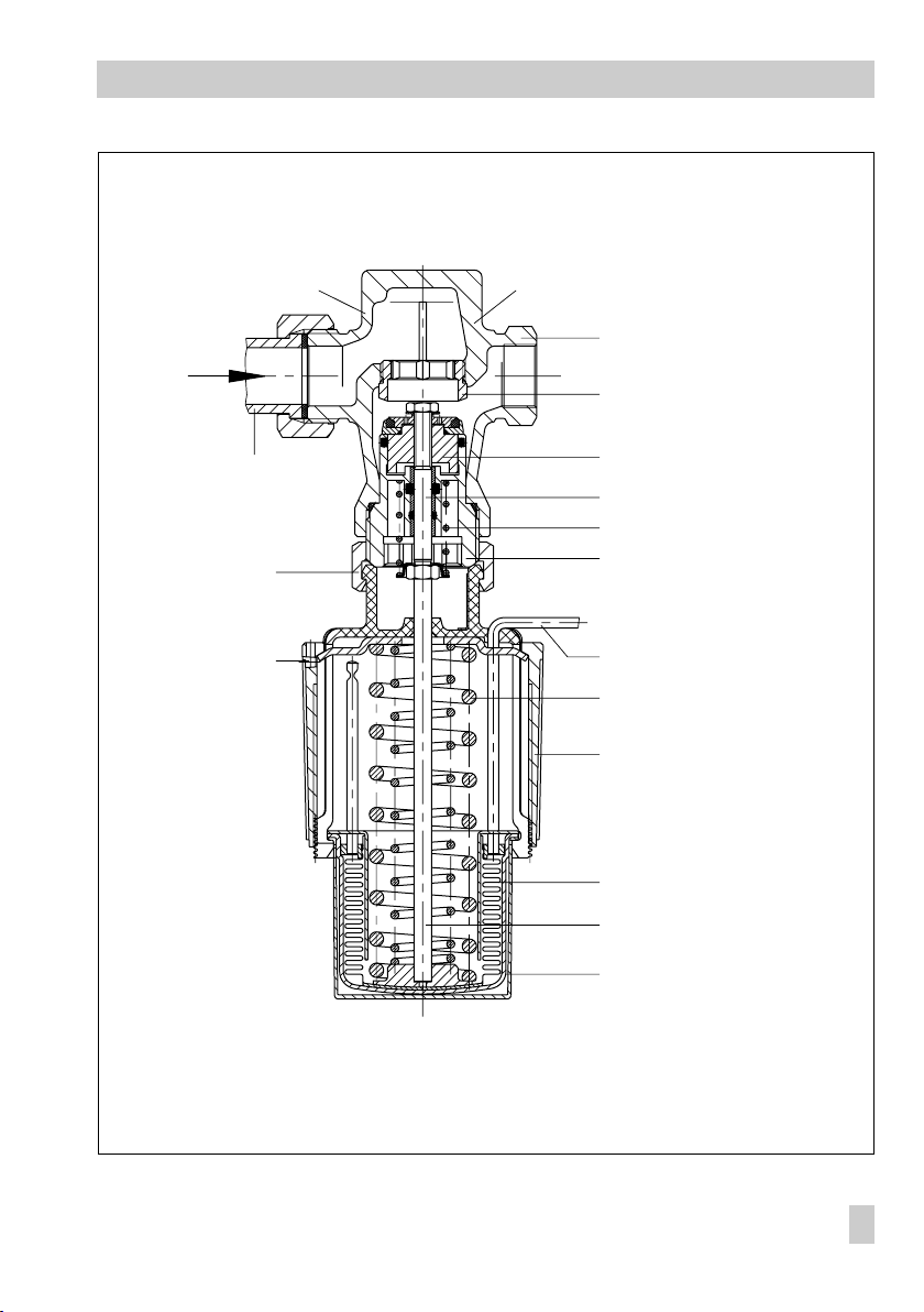
3.1 Set point adjustment
Use the black plastic ring (set point adjus-
ter 8) to set the set point while watching
the reference thermometer.
The adjustment diagrams are intended to
help you find a rough initial value.
Operation
Turning the adjuster clockwise results in
a lower temperature and turning it
counterclockwise a higher temperature.
The adjusted value can be lead-sealed at
the bore (14) in the set point adjuster.
Set point range°CChange in set
0 to 35
25 to 70
40 to 100
50 to 120
70 to 150
po in t p er tu rn
2.5 9.5
216
39.5
216
49.5
316
49.5
4.5 16
4.5 9.5
516
Sensor
diameter
Set point ranges for DN 15 to 25
with sensor Ø 9.5
˚C
150
140
120
100
80
60
40
20
0
01234
Fig. 4 ⋅Adjustment diagrams
˚C
70...150
50...120
40...100
25...70
0...35
Tu r ns ( s c a le m a r ki n g s )
150
140
120
100
80
60
40
20
Set point ranges for DN 32 to 50
with sensor Ø 16
0
01234
70...150
50...120
40...100
25...70
0...35
EB 2171 EN
7
Page 8
Maintenance - Replacing parts
4. Maintenance - Replacing parts
The temperature regulator is maintenance
free. Nevertheless, it is subject to natural
wear, particularly at the seat and plug.
Depending on the operating conditions, the
regulator needs to be checked at regular in tervals to avoid possible malfunctions.
If the valve does not shut off tightly, this may
be due to dirt on the seat and plug, or the
valve seat and plug have become untight
due to natural wear.
The valve can be removed from the pipeline
to repair it.
Note
If you intend carrying out maintenance work on the temperature regulator, first relieve the corresponding
plant section of pressure and, depending on the process medium,
drain it as well.
Let the plant section cool down to
reach ambient temperature, if
necessary.
We recommend removing the regulator from the pipeline.
To replace the seat, a special tool is
Note:
additionally required. Refer to the
EB 029 EN (formerly WA 029 EN) for the
product numbers 2710 to 2730 (also available on the Internet at http://www.samson.de/pdf_en/e00290en.pdf).
1. Unscrew the coupling nut (15) and take
the control thermostat off the valve.
2. Use the socket wrench to unscrew the
entire plug section.
3. Thoroughly clean the seat and plug.
If the seat is damaged, use the seat
wrench (EB 029 EN) to replace the
seat.
If the plug is damaged, the entire plug
section as well as the seal ring in the
body must be replaced with new ones.
4. Proceed in the reverse order to reas semble the valve.
Insert a new seal ring for the plug sec tion in the body.
Apply a drop of "Omnifit 222" before
screwing on the plug section (tightening
torque 80 Nm).
Tighten the coupling nut of the thermostat on the valve with 20 Nm.
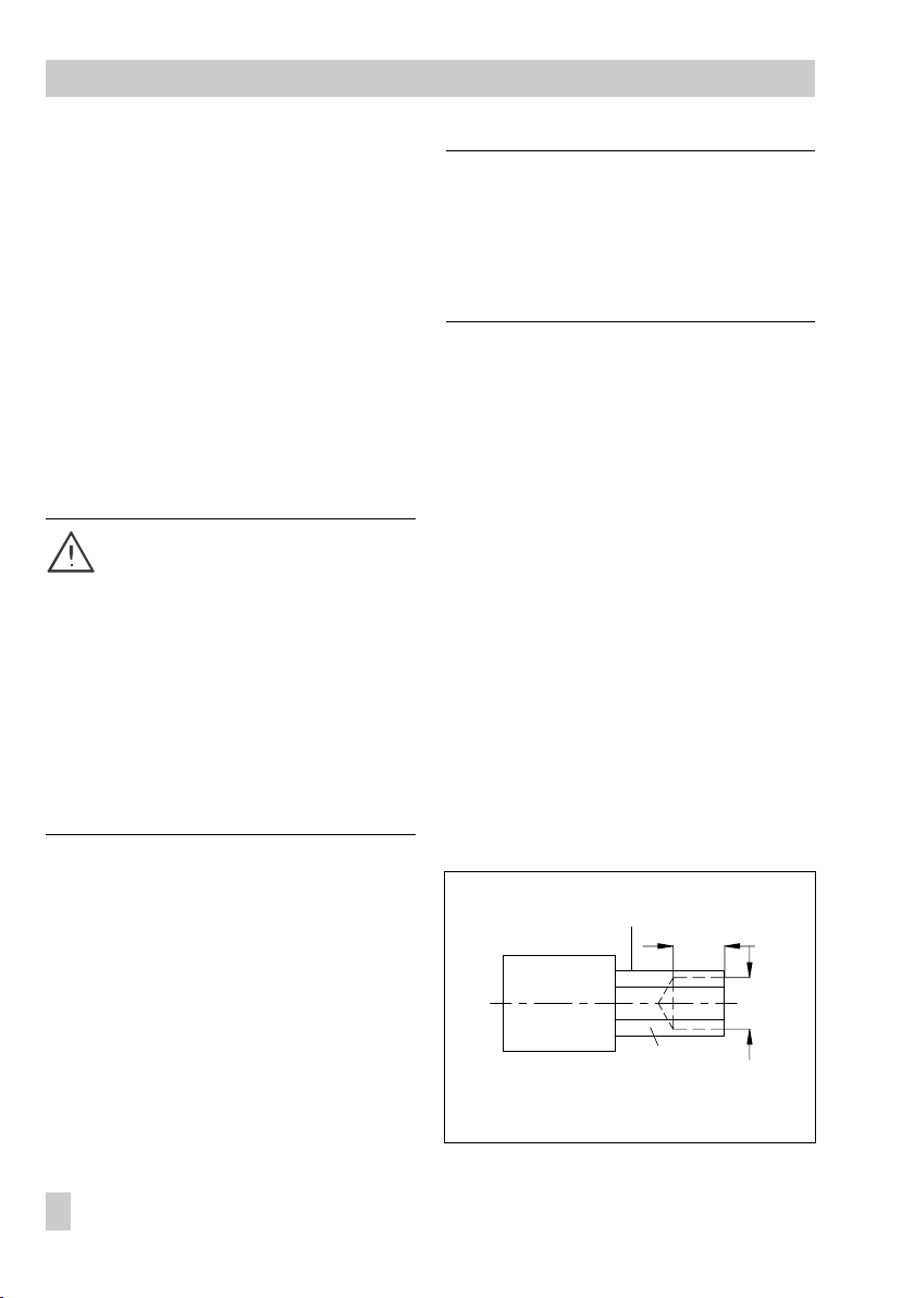
4.1 Cleaning or replacing the plug
To change the plug section (3), a special
socket wrench is needed:
For DN 15 to 25 Order no. 1280-3001,
For DN 32 to 50 Order no. 1280-3007.
For nominal sizes DN 15 to 25, this wrench
can be made, for example, from a
GEDORE screwdriver bit (IN 19-19) by drill ing a hole into the 19 mm hexagon bit as
shown in Fig. 5.
8
EB 2171 EN
19 mm hexagon bit
17
Ø 17
SW 19
Fig. 5 ⋅Socket wrench
Page 9

5. Troubleshooting
Problem Possible source Remedy
The value at
the sensor
exceeds or falls
below the set
point
The value at
the sensor
exceeds the
set point
Control loop
is unstable
Leakage at the seat and
plug
Valve is too small or too
big for the control task
Sensor is installed in the
wrong place
Safety device, e.g. STL
or STM has been
triggered
Insufficient cooling or
warming energy
available
Thermostat defective Send the thermostat to SAMSON for repair.
Strainer is blocked Empty strainer filter and clean it.
The medium flows
through the valve in the
opposite direction than
indicated by the arrow
Valve is too big for the
control task
Time constant is too
large for the control
loop
Remove the valve. Clean the seat and plug.
Contact SAMSON after-sales service if the
regulator is defective.
Recalculate the K
SAMSON.
Check whether the entire length of the sensor
is immersed in the medium or whether it is installed where delays can occur or heat can
accumulate.
Check the plant and unlock safety device.
Draw up an energy balance.
Remove the valve and reinstall it so that the
medium flows through the valve in the
direction indicated by the arrow.
Recalculate K
Fill the thermowell with conductive paste, or
remove thermowell or use a sensor with a
smaller time constant.
Troubleshooting
value and contact
VS
value and contact SAMSON.
VS
EB 2171 EN
9
Page 10
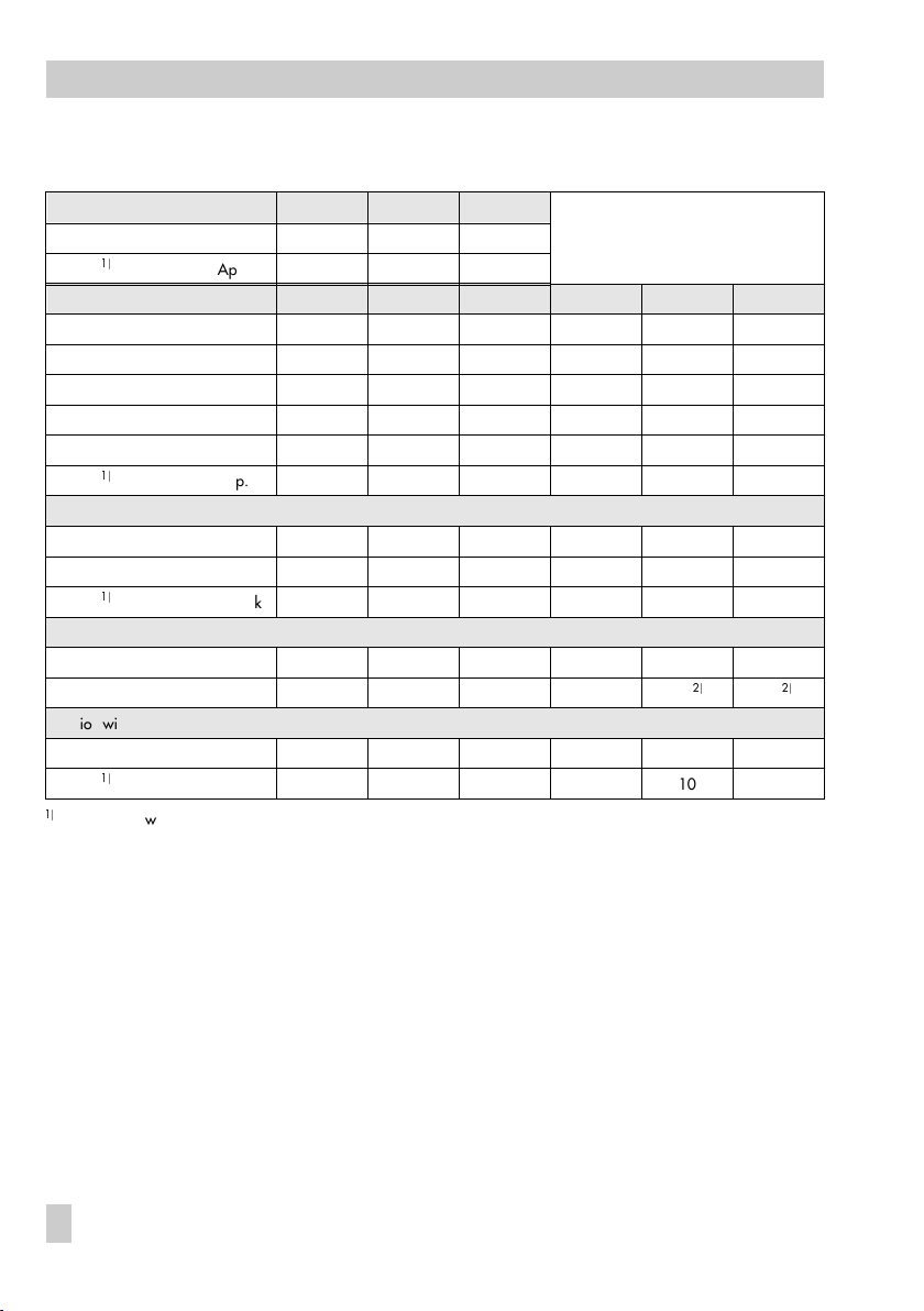
Dimensions in mm and weights
6. Dimensions in mm and weights
Type 43-1
Nom. size G 1/2 3/4 1
Length L 65 75 90
Wei ght
Type 43-2
Nom. sizeDN152025324050
Pipe Ød 21.3 26.8 33.7 42 48 60
R G 3 /4 G 1 G 1 1 /4 G 1 3/ 4 G 2 G 2 1 /2
Width across flats SW 303646596582
Length L 65 70 75 100 110 130
L1 with weld-on fittings 210 234 244 268 294 330
Wei ght
Special version with threaded ends (male thread)
Length L2 129 144 159 180 196 228
Ma le thr ea d A G 1 /2 G 3/ 4 G 1 G 1 1/ 4 G 1 1 /2 G 2
Wei ght
Special version with flanges PN 16/25
Length L3 130 150 160 180 200 230
Weight App. kg 3.1 4 4.8 7.6 9.1
Version with flanged valve body
L3 200 230
Wei ght
App. kg 10 13.2
For versions with bulb sensor and thermowell, versions without thermowell: minus 0.2 kg
App kg 1.4 1.5 1.6
App. kg1.7 2 2.34.45.15.9
App. kg1.7 2 2.34.45.15.9
11
10
EB 2171 EN
Page 11
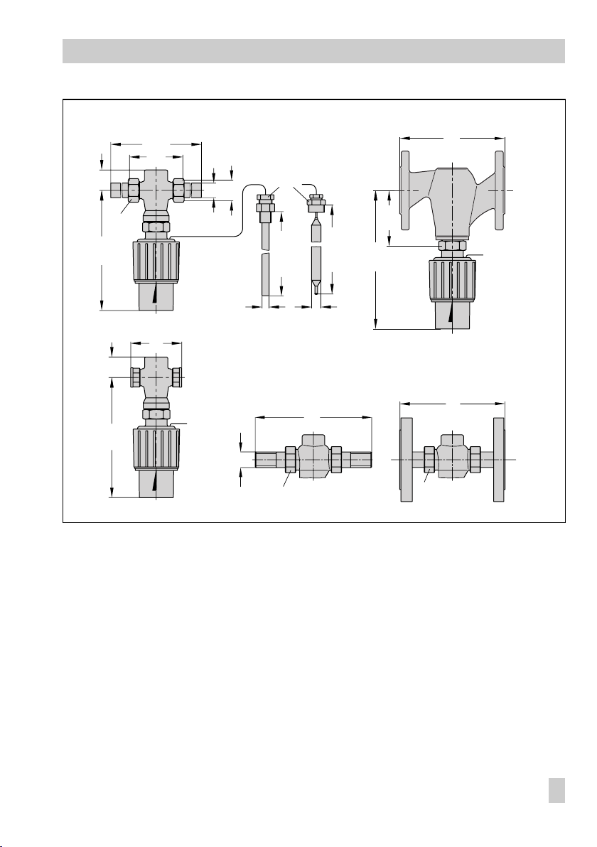
Typ e 43 -2
30
(55)
with threaded ends
L1
L
Values in parentheses for DN 32 to 50
G½
(G¾)
R
d
Dimensions in mm and weights
Type 43-2
with flanged valve body
L3
SW
180
(230)
Ø12(19) Ø9.5(16)
30180
Type 43-1
L
Bul b s en so r w ith t he rm ow el l o r
screwed gland
Type 43-2
A
7. Customer inquiries
Should you have any questions, please submit the following details (see nameplate):
Type and nominal size
Product and order numbers
Pressures upstream and downstream of
the valve
Process medium and temperature
Minimum and maximum flow rate
Has a strainer been installed?
Installation drawing
220
185(220)
SW
185(220)
with weld-on fittings with flanges
L2
220
SW
Sensor with
Ø 16 only
L3
EB 2171 EN
11
Page 12

SAMSON AG ⋅ MESS- UND REGELTECHNIK
Weismüllerstraße 3 ⋅ 60314 Frankfurt am Main ⋅ Germany
Phone: +49 69 4009-0 ⋅ Fax: +49 69 4009-1507
Internet: http://www.samson.de
EB 2171 EN
S/Z 2003-09
 Loading...