

Page 1
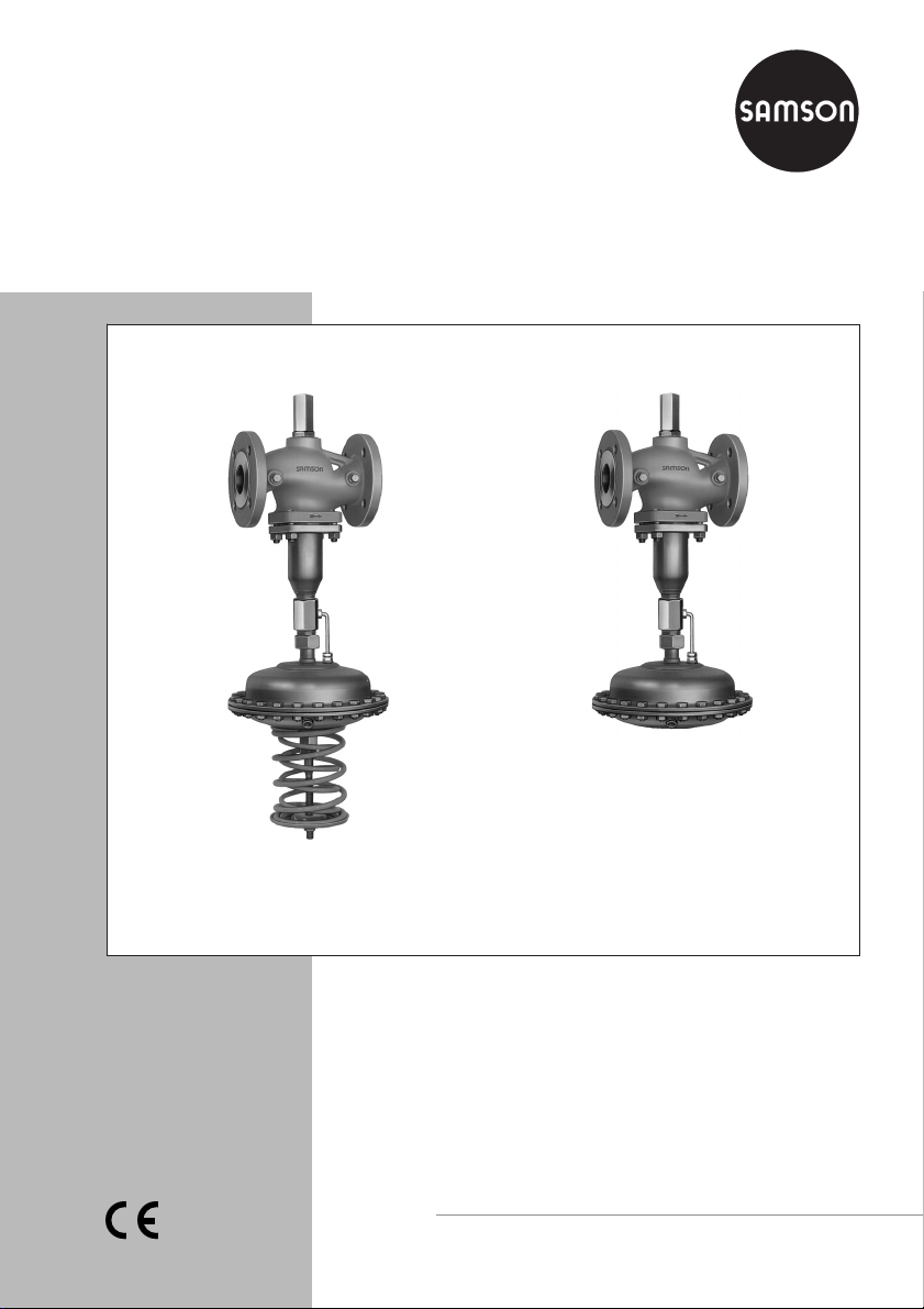
Self-operated Regulators
Differential Pressure Regulators with
Flow Limitation
Type 42-34 · Type 42-38
Type 42-34
Type 42-38
Mounting and
Operating Instructions
EB 3013 EN
Edition July 2009
Page 2

Contents
Contents Page
1 Design and principle of operation . . . . . . . . . . . . . . . . . . . . . . 4
2 Installation . . . . . . . . . . . . . . . . . . . . . . . . . . . . . . . . . 6
2.1 Mounting position . . . . . . . . . . . . . . . . . . . . . . . . . . . . . . 7
2.2 Strainer. . . . . . . . . . . . . . . . . . . . . . . . . . . . . . . . . . . 7
2.3 Shut-off valve . . . . . . . . . . . . . . . . . . . . . . . . . . . . . . . . 7
2.4 Pressure gauge . . . . . . . . . . . . . . . . . . . . . . . . . . . . . . . 8
2.5 Control line, equalizing tank and needle valve . . . . . . . . . . . . . . . . 8
3 Operation . . . . . . . . . . . . . . . . . . . . . . . . . . . . . . . . . 9
3.1 Start-up. . . . . . . . . . . . . . . . . . . . . . . . . . . . . . . . . . . 9
3.2 Set point adjustment . . . . . . . . . . . . . . . . . . . . . . . . . . . . 10
3.2.1 Adjusting the differential pressure . . . . . . . . . . . . . . . . . . . . . . 10
3.2.2 Adjusting the flow restriction . . . . . . . . . . . . . . . . . . . . . . . . 10
3.2.3 Pressure conditions in the plant and regulator . . . . . . . . . . . . . . . . 12
3.3 Decommissioning . . . . . . . . . . . . . . . . . . . . . . . . . . . . . 13
4 Maintenance · Troubleshooting . . . . . . . . . . . . . . . . . . . . . . 18
4.1 Replacing the operating diaphragm . . . . . . . . . . . . . . . . . . . . 19
5 Nameplates . . . . . . . . . . . . . . . . . . . . . . . . . . . . . . . . 21
6 Dimensions and weights. . . . . . . . . . . . . . . . . . . . . . . . . . 22
7 Customer service . . . . . . . . . . . . . . . . . . . . . . . . . . . . . 24
8 Technical data. . . . . . . . . . . . . . . . . . . . . . . . . . . . . . . 24
Definitions of the signal words used in these instructions
WARNING!
WARNING indicates a hazardous situation
Note: Supplementary explanations, informa
tion and tips
which, if not avoided, could result in death or
serious injury.
NOTICE
NOTICE indicates a property damage
message.
2 EB 3013 EN
-
Page 3
Safety instructions
General safety instructions
The regulators must be installed, started up and serviced by fully trained and
4
qualified personnel only, observing the accepted industry codes and practi
ces. Make sure employees or third persons are not exposed to any danger.
The regulator complies with the requirements of the European Pressure Equip
4
ment Directive 97/23/EC. The declaration of conformity issued for a valve
bearing the CE marking includes information on the applied conformity as
sessment procedure.
The declaration of conformity can be provided on request.
For appropriate operation, make sure that the regulator is only used in appli
4
cations where the operating pressure and temperatures do not exceed the
operating values based on the sizing data submitted in the order.
Note that the manufacturer does not assume any responsibility for damage
4
caused by external forces or any other external factors.
Any hazards whichcould be causedin the regulatorby the processmedium or
4
operating pressure are to be prevented by means of appropriate measures.
Proper shipping and appropriate storage are assumed.
4
-
-
-
-
Note: Non-electric valve versions which do not have a valve body lined with an insulating coa
ting donot have theirown potential ignitionsource according tothe ignition risk assessment sti
pulated in EN 13463-1: 2001, section 5.2, even in the rare incident of an operating fault. The
refore, they do not fall within the scope of Directive 94/9/EC.
For the connection to equipotential bonding, observe section 6.3 in EN 60097-14: 1977
(VDE 0165, Part 1)
EB 3013 EN 3
-
-
-
Page 4

Design and principle of operation
1 Design and principle of
operation
The differential pressure regulators are used
to maintain the differential pressure between
the high-pressure and the low-pressure pipe
at a set point which is either fixed (Type
42-38) or adjustable (Type 42-34). The re
striction built into the valve body allows for
limitation of the flow rate.
The regulators basically consist of a valve
with a seat, plug and restriction as well as a
closing actuator with an operating dia
phragm. The valve and actuator are deliv
ered in separate packaging and need to be
connected on siteusing the coupling nut(11).
The process medium flows through the valve
in the direction indicated by the arrow. The
free areasof flow releasedby the orifice(1.4)
and the valve plug (3) determine the flow rate
.
and the differential pressureΔp
V
the plant.
Fully balanced valves ensure that the up-
stream and downstream forces acting on the
valve plug are eliminated by a balancing bel
lows (5) or a balancing diaphragm (5.1). The
principle of operation of the regulators with
valves balanced by a bellows or by a dia
phragm only differ concerning their pressure
balancing. Valves balanced by a diaphragm
(DN 125 to 250 only) have a balancing dia
phragm instead of a balancing bellows (5).
The pressure downstream of the orifice (1.4)
acts on the outer surface of the metal bellows
plant
across
or balancing diaphragm and the down
stream pressure on the inside of the bellows
or diaphragm. As a result, the forces created
by the upstream and downstream pressures
acting on the valve plug are equally bal
anced.
The regulators in sizes DN 15 to 100 are
-
equipped witha connecting piece(10) forthe
low-pressure control line between the valve
and the actuator.
In differential pressure control, the high pres
sure (flow) of the plant is transmitted to the
bottom diaphragm chamber of the actuator
over the high-pressure control line. The pres
sure downstream of the orifice (1.4) acts on
the top diaphragm chamber over the hollow
plug stem and the connected low-pressure
control line. The differential pressure is converted into a positioning force at the diaphragm (13) and is used to change the position ofthe valve plug according to theforce of
the set point springs (16). Depending on the
version of the actuator, the set point springs
are installed in the actuator to provide a fixed
set point (Type 42-38), or they are located
outside to allow the set point tobe adjusted as
required (Type 42-34).
-
The restriction (1.1) is used to adjust the flow
limitation.
The force limiter (20) as well as the internal
excess pressure limiter (21) are designed to
protect the seat (2) and plug (3) against over
load in caseof extreme operating conditions.
-
-
-
-
-
Table 1 · Regulator configuration
Controller = Valve + Actuator
Type 42-34 with connecting piece (
Type 42-38 with connecting piece Type 2423 Balanced Type 2428 Fixed set point
for DN 15 to 100) Type 2423 Balanced Type 2424 Adjustable set point
4 EB 3013 EN
Page 5
Design and principle of operation
Type 42-34
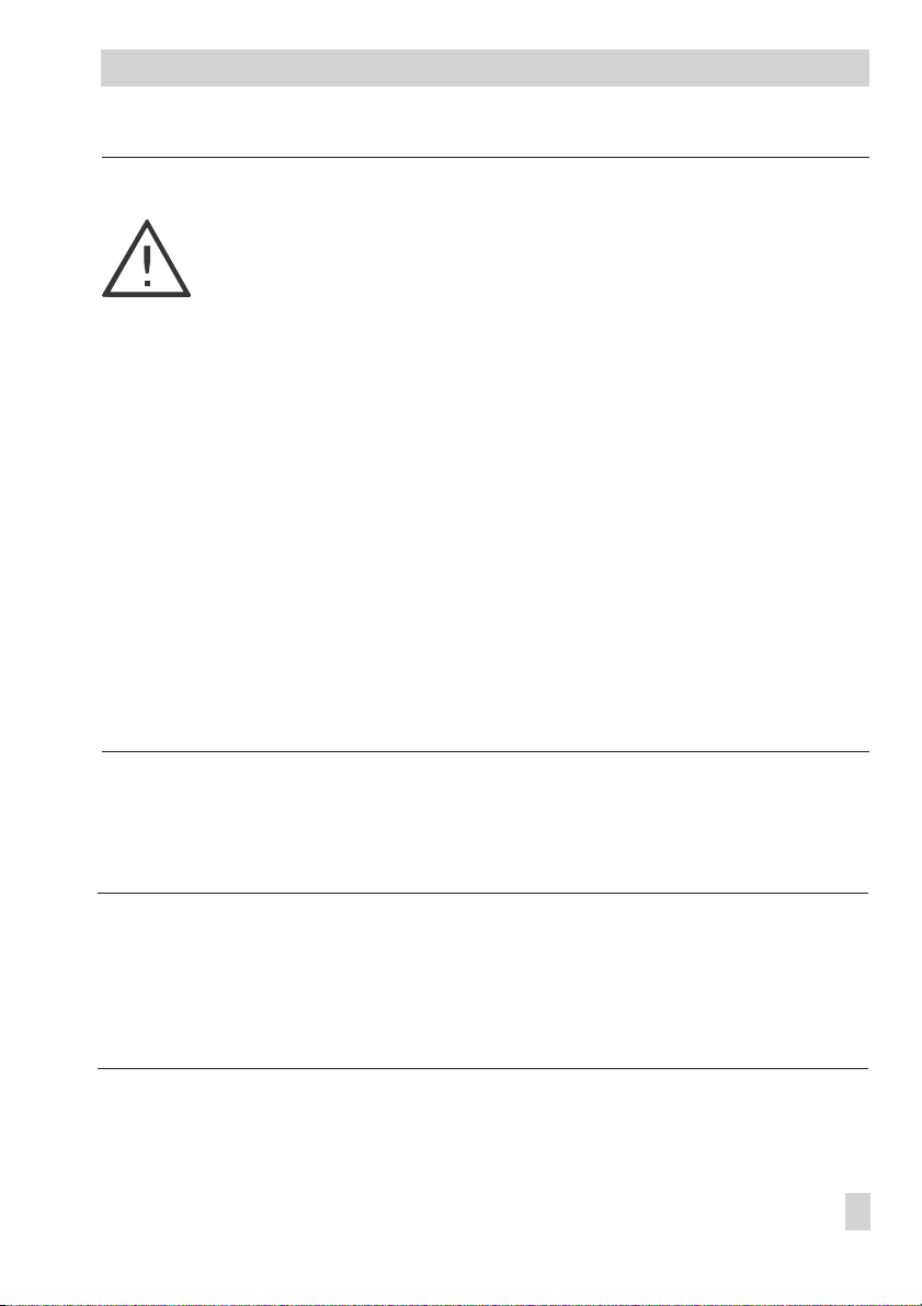
Type 42-34, Type 42-38 · Balanced by a bellows
DN 15 to 250
Type 2423 Valve
balanced by a bellows
Type 2424
Type 2428 Actuator
Actuator
1 Valve body
1.1 Restriction (for flow rate
set point adjustment)
1.2 Lock nut
1.3 Cap
1.4 Orifice
2 Seat
3 Plug
4 Plug stem
5 Balancing bellows
7 Spring
8 Venting
(DN 125 and larger)
Fig. 1 · Schematic diagrams of regulator with valve balanced by a bellows
Type 42-38
DN 15 to 100
9 Low-pressure control line
(up to DN 100)
9.1 Low-pressure control line
connection (DN 125 and larger)
10 Connecting piece (up to DN 100)
11 Coupling nut
12 Diaphragm stem
13 Operating diaphragm
14 Actuator housing
15 Screws
16 Set point springs
17 Set point adjustment (screw)
18 Nut
19 Diaphragm plate
20 Force limiter
21 Internal excess pressure limiter
EB 3013 EN 5
Page 6
Installation
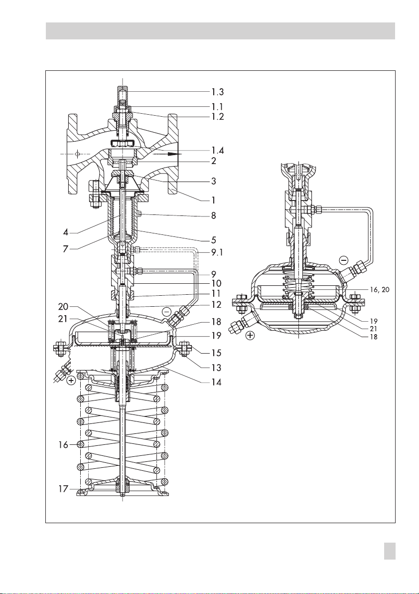
Type 2423 Valve
balanced by a
diaphragm
Type 42-34 · Balanced by a diaphragm · DN 125 to 250
Type 2424
Actuator
1 Valve body
1.1 Restriction (for flow rate
set point adjustment)
1.2 Lock nut
1.3 Cap
1.4 Orifice
Fig. 2 · Schematic diagrams of regulator with valve balanced by a diaphragm
2 Installation
See Figs. 1 and 2
The regulator must be installed in the return
flow pipe as shown in the installation sche
matic in Fig. 5.
When choosing the place of installation, en
sure the regulator can be easily accessed af
2 Seat
3 Plug
4 Plug stem
5.1 Balancing diaphragm
11 Coupling nut
12 Diaphragm stem
-
-
-
NOTICE
The regulator mustbe installed freeof stress. If
necessary, support the piping near the con
nections. However, do not attach supports to
the valve or actuator.
ter completion of the plant.
6 EB 3013 EN
-
Page 7
Installation
Note: Install a strainer (e.g. SAMSON
Type 2 N/2 NI) upstream of the regulator to
prevent sealing particles, welding spatter or
other impurities carried along by the process
medium from impairing the proper function
ing of the valve, especially tight shut-off.
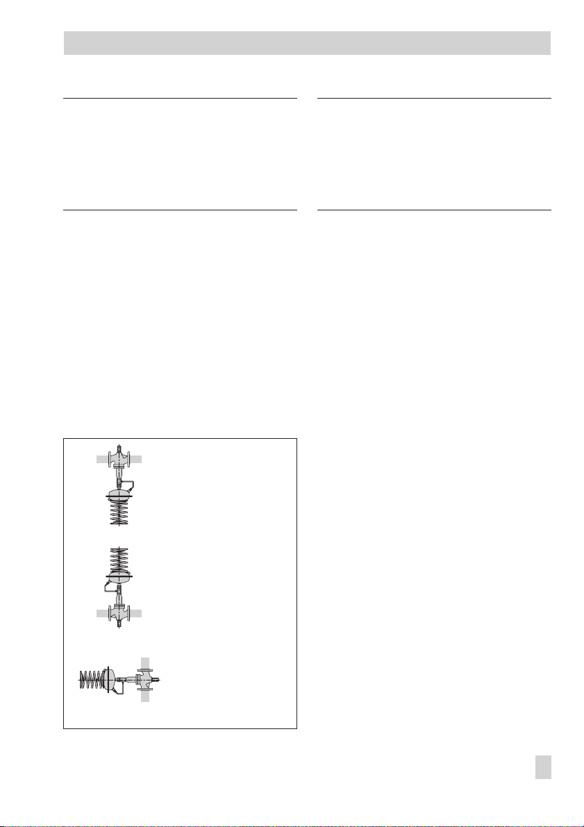
2.1 Mounting position
See Fig. 3 for permissible mounting positions.
Standard installation · Install the valve with
out the actuator in a horizontal pipeline with
the connection for the actuator facing downwards. Make sure the medium flows through
the valve in the direction indicated by the arrow. Then connect the actuator (and the connecting piece (10) for versions in sizes DN 15
to 100) to the valve using the coupling nut
(11).
–
Standard mountingposition
– all versions –
–
All versions
up to max. 80 °C
NOTICE
Protect the regulator when it is used to control
freezing process media.
On shutting down the plant in areas not free
from frost, depressurize and empty the regu
lator and remove it from the pipeline.
2.2 Strainer
A strainer installed in the flow pipe (Fig. 5)
prevents foreign matter and dirt particles in
the medium from entering the regulator. The
SAMSON product range includes the
Type 2 N/2 NI Strainer (refer to Data Sheet
T 1010 EN).
Install the strainer upstream of the regulator.
Make sure the direction of medium flow corresponds with the direction indicated by the
arrow on the strainer. The filter element must
be suspended downwards. Remember to
leave enough space to remove it.
2.3 Shut-off valve
We recommend installing a hand-operated
shut-off valve (Fig. 5) both upstream of the
strainer and at the outlet of the return flow
pipe to be able to shut down the plant for
cleaning and maintenance, and when the
plant is not used for longer periods of time.
-
–
Only versions with fixed
plug guide and
up to max. 80 °C
Fig. 3 · Permissible mounting positions
2.4 Pressure gauge
To monitor the pressures in the plant, install a
pressure gauge both upstream and down
stream of the regulator (Fig. 5).
EB 3013 EN 7
-
Page 8

Installation
2.5 Control line, equalizing tank
and needle valve
Control lines · After mounting the actuator,
fasten the supplied high-pressure control line
to the regulator (standard: 8 mm pipe diame
ter) routing it from the bottom diaphragm
chamber to the high-pressure line (flow pipe)
of the plant. Attach the low-pressure control
line to the regulator as shown in Figs. 1 and
2.
The controlline to be installed on site for pres
sure tapping at the pipeline must be at least
three times the nominal size (DN) away from
pipe fittings or instruments thatcause flow tur
bulence (e.g. pipe bends, manifolds,pressure
measuring points or other valves) (see Fig.
4.1). How the lines are routed generally de-
pends on the installation location. Preferably
connect the control line at the side of the main
pipeline (Fig. 4.4).
Do not change the pipe diameter of the main
pipeline so that it is off-center!
Control line kit · A control line kit for tapping
pressure directly at the valve body is avail
able as an accessory from SAMSON. Refer to
Data Sheet T 3095 EN.
Equalizing tank · An equalizing tank is re
quired for liquids above 150 °C. Install an
equalizing tank in the control line directly
downstream of the pressure tapping point.
The mounting position of the equalizing tank
is indicated by an adhesive label on the tank
itself as well as by an arrow and the word
"top" stamped onto the top of the tank. Ad
here to the mounting position and distances
prescribed, otherwise the safe functioning of
the regulator cannot be guaranteed.
Correct!
-
4.4 · Connection at the side – correct
Incorrect!
-
4.3 · Connection at the top – incorrect
-
Incorrect!
4.2 · Connection at the bottom – incorrect
-
-
-
DN = Nominal size
4.1 · Control line connection, depending on how
the pipeline is routed
Fig. 4 · Control line connection
8 EB 3013 EN
Page 9

Operation
Needle valve · If the regulator tends to hunt,
we recommend installing a SAMSON needle
valve in the control line installed on site at the
actuator connection.
Note: Needle valves, equalizing tanks and
compression-type screw fittings can be sup
plied as required. These accessories are listed
in the Data Sheet T 3095 EN.
1 Shut-off valve
2 Strainer
3 Differential pressure regulator
4 Equalizing tank (optional)
5 Pressure gauge
6 Needle valve (optional)
7 Motorized valve
Fig. 5 · Typical installation, Type 42-34/42-38
installed in the return flow pipe
3 Operation
See Figs. 1 and 2.
3.1 Start-up
CAUTION!
First start up the regulator after mounting all
the components, e.g. valve, actuator andcon
trol line.
Make sure the control line (and needle valve)
is open and correctly connected before
start-up.
For media temperatures above 150 °C, fill
the equalizing tank with the process medium
(water) before start-up.
Note: On filling the plant, make sure the
orifice (1.4) is open byunscrewing the restriction (1.1) counterclockwiseas far asit will go.
Open all the valves on the consumer side.
4
Slowly open the shut-off valves starting on
the return flow pipe first. In case of valves
balanced by a bellows in DN 125 or
larger, vent the bellows housing at the
stopper (8) located at the side of the bel
lows housing.
Rinsing the plant · After filling the plant, first
completely open the consumers. At the regu
lator, openthe restriction counterclockwise as
far as it will go and adjust the maximum dif
ferential pressure by tensioning the set point
springs to the maximum. Rinse out the pipe
line at full flow ratefor several minutes. Check
the installed strainer (e.g. by measuring the
pressure drop) afterwards. Clean the strainer,
if necessary.
-
-
-
-
-
EB 3013 EN 9
Page 10

Operation · Set point adjustment
NOTICE
When testing the pressure of the plant when
the regulatoris already installed, the pressure
must not exceed the nominal pressure of the
valve by 1.5times nor themaximum permissi
ble differential pressure in the actuator (final
value of set point range by 1.5 times).
If higher test pressures are used, unscrew the
control lines connected to the actuator and
seal openings atthe actuator andcontrol lines
with stoppers.
3.2 Set point adjustment
3.2.1 Adjusting the differential
pressure
Type 42-34 only · Set the required differen-
tial pressure by turning the set point screw
(17) when the plant is almost closed and the
orifice (1.4) is completely open. Then adjust
the value for the flow restriction.
–
Turn clockwise= Tensioning thesprings
To increase the set point
–
Turn counterclockwise = Relieving the
springs of tension→To reduce the set
point.
How to proceed
Close motorized valve!
4
Unscrew cap (1.3) and undo lock nut
4
(1.2).
Turn the restriction (1.1) counterclockwise
4
as far as it will go (completely opening it)
to deactivate the flow restriction.
Relieve the set point springs (16) of ten
4
sion.
Open motorized valve slightly (approx.
4
10 % travel).
-
Adjust the differential pressure by
4
tensioning the set point springs at the set
point screw (17).
3.2.2 Adjusting the flow restriction
Open control and shut-off valvesas well as all
the consumers (minimum plant resistance) to
achieve the maximum flow rate.
Close the bypass, if applicable.
Adjust the desired flow limitation by turning
the restriction (1.1),monitoring the flow meter
in the heat meter (see Table 2 · Flow rate set
points for water).
Note: Always start the set point adjustment
based on a closed restriction.
–
→
Turn clockwise to close the restriction
Reduces the flow rate.
–
Turn counterclockwise to open the restric
tion→Increases the flow rate.
How to proceed
Completely close the restriction (1.1) to
4
block the flow rate
Completely open motorized valve.
4
Open restriction (1.1), turning it counter
4
clockwise, until the desired flow rate is
reached.
Initially open the restriction by one turn at
4
a time, while monitoring the flow rate at
-
→
-
-
10 EB 3013 EN
Page 11

Operation · Set point restriction
the flow meter in the heat meter. Then ad
just it in small steps until the required flow
rate is constant (generally,±2 % devia
tions are acceptable).
If therequired flow rate is not reached,the
4
differential pressure set point must be in
creased (see section 3.2.1).
When the required flow rate is reached,
4
secure the setting of the restriction (1.1)
with the lock nut (1.2). Screw back on cap
(1.3).
Lead-seal the set point setting at the set
4
point adjuster (17) and cap (1.3).
If the pressure drop in the plant is known, the
adjustment diagrams for water in Figs. 7 to
10 (pages 14 to 17) can also be used.
Example:
Adjusting the flow restriction
Determining the adjustment values using the
adjustment diagram in Fig. 7.
A Type 42-34 Regulator, DN 25, set point
range 0.25 to 3.5 m³/h, is to be used in a
plant to limit the flow rate to 3.0 m³/h.
The pressure dropacross the plant is0.4 bar.
To which value do you have to adjust the dif
ferential pressure set point and how many
turns of the set point screw at the restriction
will be required?
Solution:
-
Follow the sequence from A to E in the dia
gram in Fig. 7.
The pressure dropΔp across the plant serves
as a basis. This value must be known!
AssumingΔp = 0.4 bar, this value corre
sponds to point A in the diagram. Add the
upper differential pressure across the restric
tionΔp
A horizontal line corresponding to this value
is drawn from A to the right-hand side, result
ing in point B. Point B is located on the
straight line associated with the differential
pressureΔp to be adjusted =0.6 bar (see section 3.2.1).
From point B, the line is further drawn vertically downward to the desired limiting curve
for the flow rate (3.0 m³/h), resulting in point
C.
Then, plot the line from point C straight to the
curve associated with the nominal size and
you will reach point D.
The vertical line above point D which meets
point E shows the required number of turns of
the set point screw.
Result: approx. 1.9 times
Based on a closed restriction, the set point
-
screw must be turned counterclockwise
approx. 1.9 times.
, assumed to be 0.2 bar.
restriction
-
-
-
-
EB 3013 EN 11
Page 12

Operation
3.2.3 Pressure conditions in the plant and regulator
When selecting the differential pressure set point or set point range, it is important to observe
that the differential pressure set pointΔp
across the completely open plantΔp
tion)Δp
restriction
.
plant
Table 2 list the flow rates with the known upper differential pressure value at the restriction for
Type 2423 Valves balanced by a bellows and balanced by a diaphragm.
set point
=Δp
p
Δ
The minimum required differential pressureΔp
is calculated as follows:
=Δp
p
Δ
min
Fig. 6 shows a schematic diagram of the plant’s pressure conditions.
Δp
is calculated from the known pressure drop
set point
and the pressure drop directly at the orifice (restric
+Δp
set point
Δp
Δp
set point
plant
plant
min
min
restriction
between the flow pipe and return flow pipe
2
&
⎛
⎞
V
⎜
⎟
+
⎜
⎟
K
VS
⎝
⎠
Δp
restriction
-
p
1
p
Δ
p
Δ
p
Δ
Fig. 6 · Pressure conditions in the plant
Minimum differential pressure between
min
flow and return flow pipes in bar
Pressure drop at restriction in bar
restriction
Differential pressure set point adjusted
set point
at the regulator in bar
12 EB 3013 EN
p
2
Type 42-34
or
Type 42-38
p
Δ
&
V
K
VS
Differential pressure (pressure drop) across
plant
a completely open plant in bar
Flow rate adjusted in m³/h
Valve flow coefficient in m³/h
Page 13

Operation
Table 2 · Flow rate set points for water in m³
/h
Type 2423 Valve balanced by a bellows
p
p
p
Δ
Δ
set p.
plant
0.2
0.1
bar
bar
0.5
0.3
bar
bar
1.0
0.5
bar
bar
Max. perm. diff. pressureΔp
DN ... 15 20 25 32 40 50 65 80 100 125 150 200 250
Δ
restr.
.
0.05 0.15 0.25 0.4 0.6 0.9 2 3.5 6.5 11 18 20 26
min
0.1
V
bar
0.2
bar
0.5
bar
V
V
1.4 2.1 2.4 4.9 7.7 11.2 19 28 44 56 84 126 154
max
.
2 3 3.5 7 11 16 28 40 63 80 120 180 220
max
.
3 4.5 5.3 9.5 16 24 40 58 90 120 180 260 300
max
25 bar 20 bar 16 bar 12bar 10 bar
Type 2423 Valve balanced by a diaphragm
Nominal size DN 125 150 200 250
Flow rate set points in m³/h with
Δ
Max. perm. diff. pressureΔp
p
restriction
= 0.2 bar
11 to 120 18 to 180 20 to 320 26 to 350
12 bar 10 bar
3.3 Decommissioning
Preferably close the shut-off valves starting
from the flow pipe side and then return flow
pipe side.
EB 3013 EN 13
Page 14

Operation
p (bar)
Δ
Pressure drop across the plant
Differential pressure set point
(fixed for Type 42-38, adjustable Type 42-34)
1.6
1.4
Turns of the set point adjuster
3
2
E
DN 15
DN 20
DN 25
DC
1.2
1.0
1.2
0.8
1.0
0.6
0.4
A
0.2
1
0.1
0.2
0.8
B
0.6
0.4
1.6
1.4
1.8
0.6
1.2
1.8
2.4
3.0
3.6
4.2
4.8
5.4
˚
V
max
3
m
/h
Adjustment diagram based on water!
Fig. 7 · Adjustment diagram DN 15 to 25
14 EB 3013 EN
0.2 0.4
0.5
Upper diff. pressureΔp
Page 15

p (bar)
Δ
Pressure drop across the plant
Differential pressure set point
(fixed for Type 42-38, adjustable Type 42-34)
1.6
1.4
Operation
Turns of the set point adjuster
6
4
DN 40
DN 50
DN 32
1.2
1.0
1.2
0.8
1.0
0.6
0.4
0.2
0.2
2
0.1
0.8
0.6
0.4
1.6
1.4
1.8
˚
V
3
m
3.0
6.0
9.0
12.0
15.0
18.0
21.0
24.0
27.0
max
/h
Adjustment diagram based on water!
Fig. 8 · Adjustment diagram DN 32 to 50
0.2 0.4
0.5
Upper diff. pressureΔp
EB 3013 EN 15
Page 16

Operation
p (bar)
Δ
Pressure drop across the plant
Turns of the set point adjuster
8765 32110 9
DN 65
DN 80
4
1.6
1.4
1.2
1.0
0.8
0.6
0.4
0.2
0.1
0.2
Differential pressure set point
(fixed for Type 42-38,
adjustable Type 42-34)
1.8
1.6
1.4
1.2
1.0
0.8
0.6
0.4
˚
V
max
3
m
/h
8
16
24
32
40
48
56
64
72
80
90
Adjustment diagram based on water!
DN 100
Fig. 9 · Adjustment diagram DN 65, DN 80 and DN 100
16 EB 3013 EN
0.2 0.4
0.5
Upper diff. pressureΔp
Page 17

p (bar)
Δ
Pressure drop across the plant
Operation
Differential pressure set point
(fixed for Type 42-38, adjustable Type 42-34)
1.6
1.4
Turns of the set point adjuster
12
8
DN 125
DN 150
1.2
1.0
1.2
0.8
1.0
0.6
0.4
0.2
0.2
4
0.1
0.8
0.6
0.4
1.6
1.4
1.8
˚
V
m
20
40
60
80
100
120
140
160
180
200
max
3
/h
Adjustment diagram based on water!
Fig. 10 · Adjustment diagram DN 125 and DN 150
0.2 0.4
0.5
Upper diff. pressureΔp
EB 3013 EN 17
Page 18

Maintenance · Troubleshooting
4 Maintenance ·
Troubleshooting
The regulators are maintenance free. Never
theless, they are subject to natural wear, par
ticularly at the seat, plug and operating dia
phragm.
Depending on the operating conditions, the
regulator needs to be checked at regular in
tervals to avoid possible malfunctions.
CAUTION!
On performing any work on the regulator,
make sure the relevant section of the pipeline
-
is depressurized and, depending on the pro
-
cess medium, drained as well.
-
For high temperatures, allow the regulator to
cool down to ambient temperature before
starting any work on it.
-
Interrupt or shut off the control line to avoid
any hazards which could be caused by mov
ing parts.
As valves are not free of cavities, remember
that residual process medium might still be
contained in the valve.
We recommend to remove the valve from the
pipeline after it has been depressurized and
drained. Make sure that all the plant sections
connected to the control line are also
depressurized. If this is not the case, shut off
the control line.
Details on malfunctions and the recommended action can be found in the Ta-
ble 3 · Troubleshooting.
Proceed as described in section 4.1 if the op
erating diaphragm is defective.
-
-
-
18 EB 3013 EN
Page 19

Maintenance · Troubleshooting
Table 3 · Troubleshooting
Malfunction Possible reasons Recommended action
Remove valve from pipeline. Clean seat and plug.
Flow rate or
differential
pressure
exceeds the flow
.
or
rate
V
differential
pressure set
point.
Flow rate or
differential
pressure does
not reach the
flow rate
.
or
V
differential
pressure set
point.
Control loop
hunts
Seat and plug leak
Operating diaphragm defective
Control line blocked
Valve too large to regulate the
flow rate or too small to regulate
the differential pressure
Wrong set point range selected
Safety equipment, e.g. pressure
limiter, has been triggered
Insufficient pressure drop across
the plantΔp
Strainer blocked Drain and clean filter of the strainer.
Direction of flow, valve incorrect-
ly installed
Valve too large for control task
Restriction (or needle valve) is
missing in a control line to dam
pen pulsation
Replace plug, if necessary. Otherwise send the
regulator to SAMSON for repair.
Replace diaphragm (see section 4.1) or send the
regulator to SAMSON for repair.
Remove control line and clean it.
Check and clean the screw joint with orifice plate.
Recalculate K
for further action.
coefficient and contact SAMSON
VS
Check set point range and contact SAMSON for
further action.
Check plant and unlock safety equipment.
Compare existing differential pressure across the
plant with the plant’s drag:
Min. differential pressure across the plant
p
=Δp
Δ
min
restriction
+ (
.
VK
/
2
+Δp
)
VS
Install the valve so that the direction of flow is the
same as indicated by the arrow.
Recalculate K
for further action.
coefficient and contact SAMSON
VS
Install a needle valve in the control line and start
-
to close it until the control loop becomes stable.
NOTICE Do not completely close needle valve.
Contact SAMSON if the malfunction cannot be remedied using the above table.
plant.
4.1 Replacing the operating
diaphragm
See Figs. 1 and 2.
If just the operating diaphragm is defective, it
can bereplaced without having to remove the
valve from the pipeline. Relieve the relevant
section of the pipeline of pressure and drain
it. Unscrew the control lines and separate the
actuator from the valve.
EB 3013 EN 19
Page 20

Maintenance · Troubleshooting
Type 2428 Actuator
1. Place actuator upside down.
2. Undo screws (15) at the actuator. Pull out
the top cover (+ chamber) together with
diaphragm plate (19) and diaphragm
(13) as wellas the diaphragm stem(12).
3. Unscrew nut (18), while holding the dia
phragm stem stationary using a suitable
tool.
4. Lift off diaphragm plate (19) and pull out
diaphragm (13).
5. Check the diaphragm stem (12) for scor
ing and replace it with a new one, if nec
essary.
NOTICE
The stem surface is roller-burnished. Never
regrind the stem!
6. Insert a new diaphragm.
7. Proceed in the reverse order to reassemble the actuator. Secure nut (18) from
turning with suitable adhesive (e.g.
8121-0230 from SAMSON). Use lubri
cant from SAMSON (8150-0111).
8. Check screw fittings for dirt and clean
them, if necessary.
Start up as described in section 3.1.
Type 2424 Actuator
1. Place actuator upside down.
2. Relieve set point springs (16) completely
of tension byturning the setpoint adjuster
(17) counterclockwise.
3. Take off set point springs (16) and set
point adjuster (17).
4. Undo screws (15) at the actuator. Re
move topcover (+ chamber)and take out
inner springs in the + chamber.
5. Lift out diaphragm plate (19) together
-
-
-
with diaphragm (13), diaphragm stem
(12) and excess pressure limiter unit . Re
move forcelimiter (20) together with stem
(12).
6. Check stem (12) for scoring and replace
it with a new one, if necessary.
NOTICE
The stem surface is roller-burnished. Never
regrind the stem! When exchanging the diaphragm stem, the nipple (guide bushing) in
the actuator cover must also be replaced.
7. Unscrew nuts (18) and pull out diaphragm stem.
8. Remove diaphragm (13) and insert a
new diaphragm.
9. Insert diaphragm stem. Tighten nuts (18)
to fix diaphragm, diaphragm plate and
washer into place. Secure nut (18) from
turning with suitable adhesive (e.g.
8121-0230 from SAMSON).
10. Proceed in the reverse order to reassem
ble the actuator. Use lubricant
(8150-0111).
11.Check screw fittings for dirt and clean
them, if necessary.
Start up as described in section 3.1.
-
-
-
20 EB 3013 EN
Page 21

5 Nameplates
Nameplates
Valve nameplates
DIN version
ANSI version
Actuator nameplate
Valve
1 Valve type
2 Model number
3 Model number index
4 Order number or order date
coefficient
5K
VS
8 Nominal size
9 Nominal pressure
10 Perm. differential pressure in bar
11 Perm. temperature in °C
12 Body material
ANSI version
5 Nominal size
8 Perm. differential pressure in psi
9 Perm. temperature in °F
10 Body material
V coefficient (K
11 C
12 ANSI Class (pressure rating)
Actuator
1 Model number
2 Model number index
3 Order number or order date
4 Effective diaphragm area
5 Labeling acc. to DIN
6 Labeling acc. to ANSI
7 Max. perm. pressure
8 Nominal size
9 Differential pressure at restriction
10 Set point range
11 Diaphragm material
12 Year of production
VS
x 1.17)
Fig. 11 · Nameplates
EB 3013 EN 21
Page 22

Dimensions and weights
6 Dimensions and weights
Valve balanced by a bellows
Type 42-38
Valve balanced by a bellows
– see Table 5 on p. 23 –
Fig. 12 · Dimensions, valve balanced by a bellows
Valve balanced by a diaphragm
Type 42-34 ·
Valve balanced by a bellows
– see Table 5 on p. 23 –
Table 4 · Dimensions in mm and weights
Type 42-34 · Valve balanced by a diaphragm
Nom. size DN 125 150 200 250
Length L
Height H1
Height H2
Weight in kg
1)
With 640 cm² actuator
Fig. 13 · Dimensions, valve balanced by a diaphragm
400 480 600 730
720 745 960
295 325 345 375
95 115
1)
2901)305
22 EB 3013 EN
1)
Type 42-34 · Balanced by a diaphragm
Page 23

Dimensions and weights
Table 5 · Dimensions in mm and weights · Type 24-34, Type 24-38 · Balanced by a bellows
Nominal size DN 15 20 25 32 40 50 65 80 100 125 150 200 250
Length L
Height H1
Height H2
Other materials
Forged steel
Type 42-34 Differential Pressure Regulator with Flow Limitation · Balanced by a bellows
Set point
range
0.1 to
0.6 bar
Height H
Actuator
Weight
1)
Height H
Set point
range
0.2 to 1 bar
Set point
range
0.5 to
1.5 bar
Actuator
Weight
Height H
Actuator
Weight
1)
1)
Type 42-38 Differential Pressure Regulator with Flow Limitation · Balanced by a bellows
Height H
Set point
range
0.2 0.3
0.4 · 0.5 bar
Actuator
Weight
1)
in kg
1)
The weight is based on the version made of EN-JL1040/PN 16 (GG-25). +10 % for other materials
2)
Optionally with 320 cm² actuator
130 150 160 180 200 230 290 310 350 400 480 600 730
285 360 415 460 590 730
115 135 195 220 265 295 400
113 − 130 − 155 161 −−−−−−−
670 745 800 990 1120 1260
Ø D = 285 mm
Ø D = 225 mm ⋅ A = 160 cm²
16 16.5 17.5 24 24.5 27 46 51 65 135 185 425 485
in kg
2)
A = 320 cm²
Ø D = 390 mm
A = 640 cm²
670 745 800 990 1120 1260
Ø D = 225 mm ⋅ A = 160 cm²
16 16.5 17.5 24 24.5 27 42 47 61 135 185 425 485
in kg
2)
Ø D = 390 mm
A = 640 cm²
670 745 800 880 1040 1210
Ø D = 225 mm ⋅ A = 160 cm²
16 16.5 17.5 24 24.5 27 42 47 61 125 175 415 475
in kg
2)
Ø D = 285 mm
A = 320 cm²
450 525 585
Ø D = 225 mm ⋅ A = 160 cm²
Ø D = 285 mm
A = 320 cm²
11.5 12 13 19.5 20 22.5 38 43 57
−
EB 3013 EN 23
Page 24

Customer service
7 Customer service
Should any malfunctions or any defect occur, SAMSON's After-Sales Service is prepared to
help you on site.
You can also send the defective regulator directly to your local SAMSON representative for re
pair. Addresses of SAMSON subsidiaries, agencies and service centers are listed in the prod
uct catalogs and in the Internet at www.samson.de.
To allow SAMSON to find the fault and to have an idea of the installation situation, specify the
following details (refer to the nameplate):
Type and nominal size of the valve
4
Order number and model number
4
Upstream and downstream pressure
4
Flow rate in m³/h
4
Has a strainer been installed?
4
Sketch of the installation
4
8 Technical data
-
-
Table 6 · Type 42-34, Type 42-38
Valve balanced by a bellows
Type 42-34 42-38
Nominal size
Nominal pressure
Valve body
Max. perm.
temperature
Pressure at which the internal excess
pressure limiter responds, depending
on diaphragm area A
Set point ranges
Leakage rate
1)
Higher temperatures on request
Actuator
1)
DN 15 to 250 DN 15 to 100
PN 16, 25 or 40 (acc. to DIN EN 12516-1)
See pressure-temperature diagram in T 3013 EN
With equalizing tank: Liquids up to 220 °C
Without equalizing tank: Liquids up to 150 °C
Air and gases up to 80 °C
160 cm² = 1.2 bar
320 cm² = 0.6 bar
640 cm² = 0.3 bar
0.1 to 0.6 bar ⋅ 0.2 to 1 bar
0.5 to 1.5 bar
0.05 % of K
≤
160 cm² = 0.6 bar
320 cm² = 0.3 bar
0.2 ⋅ 0.3 ⋅ 0.4 ⋅ 0.5 bar
coefficient
VS
24 EB 3013 EN
Page 25

Technical data
Valve balanced by a diaphragm
Type 42-34
Nominal size
Nominal pressure
Valve body
Max. perm.
temperature
Actuator
1)
Pressure at which the internal excess
pressure limiter responds, depending on
diaphragm area A
Set point ranges
Leakage rate
1)
Higher temperatures on request
PN 16, 25 or 40 (acc. to DIN EN 12516-1)
See pressure-temperature diagram in T 3013 EN
With equalizing tank: Liquids up to 220 °C
Without equalizing tank: Liquids up to 150 °C
0.1 to 0.6 bar ⋅ 0.2 to 1 bar · 0.5 to 1.5 bar
DN 125 to 250
Air and gases up to 80 °C
160 cm² = 1.2 bar
320 cm² = 0.6 bar
640 cm² = 0.3 bar
0.05 % of K
≤
coefficient
VS
Table 7 · Data for Type 2423 Valve
Valve balanced by a bellows · KVScoefficients, z values and max. perm. differential pressures
Nominal size DN 15 20 25 32 40 50 65 80 100 125 150 200 250
Travel
K
coefficient m³/h
VS
z value
Max. perm. diff.
pressureΔp
4 6.3 8 16 20 32 50 80 125 190 280 420 500
0.65 0.6 0.55 0.45 0.4 0.35 0.3
10 mm 16 mm 22 mm
25 bar 20 bar 16 bar 12bar 10 bar
Valve balanced by a diaphragm · KVScoefficients and max. perm. differential pressures
Nominal size DN 125 150 200 250
K
VS
m³/h
coefficient
22 mm travel
35 mm travel
Max. perm. diff. pressureΔp
190 290 550 600
250 380 650 800
12 bar 10 bar
See Table 2 on page 13 for the flow rate set points for both valve versions.
EB 3013 EN 25
Page 26

SAMSON AG · MESS- UND REGELTECHNIK
Weismüllerstraße 3 · 60314 Frankfurt am Main · Germany
Phone: +49 69 4009-0 · Fax: +49 69 4009-1507
Internet: http://www.samson.de
EB 3013 EN
S/Z 2009-09
 Loading...