

Page 1
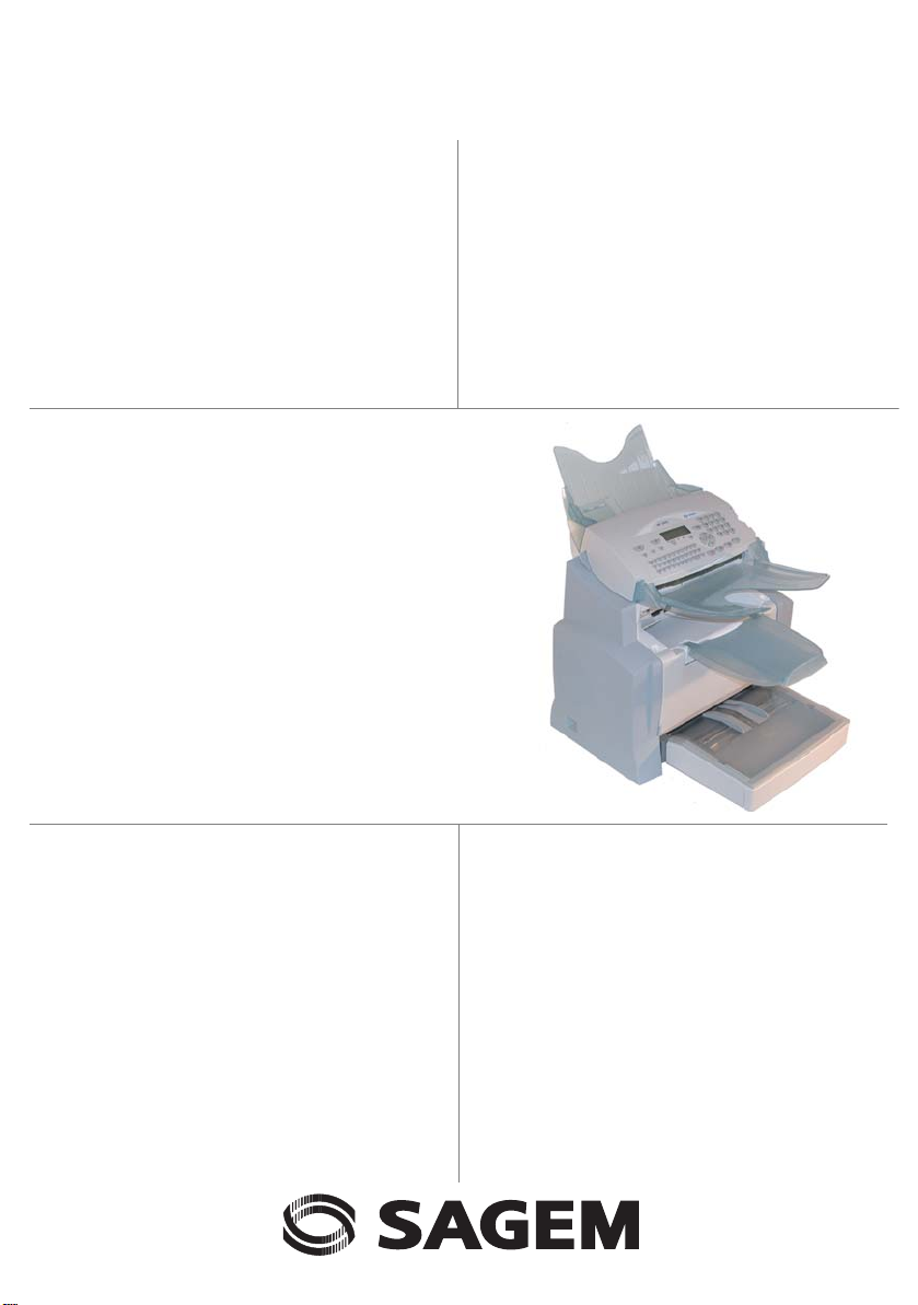
SAGEM
MF 4690n
User Manual
Page 2

WELCOME
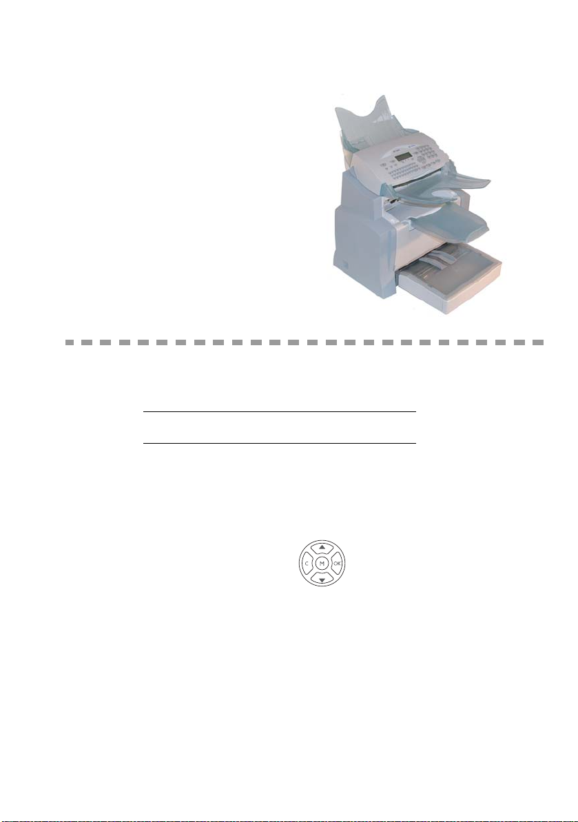
Congratulations for purchasing this SAGEM new gene ration communication terminal. This terminal is
capable of faxing, printing and scanning and furthermore, can be used for Internet communications.
Your terminal will meet all your professional requirements.
This User's Manual presents the model in the range:
Model Equipment
• Colour scanner.
MF 4690n
It combines power, user-friendliness and simplicity thanks to its navigator, its multitask access and its
direct access directory.
Providing access to the Internet, your terminal lets you, depending on model:
• send and receive faxes to E-mails thanks to the F@x to E-mail function,
• send and receive E-mails,
• send and receive SMS's
You can also print to PCL® 6 and SG Script 3 formats (emulation of Postscript® level 3
language).
We recommend that you read this Manual carefully, in order to familiarise yourself with the various
features and functions of your terminal.
1
.
• 33.6 kbps fax and 56 kbps data modem.
• 20 ppm black & white laser printer.
• LAN 10/100 Base T.
List of accessories
The following additional accessories are proposed for these models:
• Directory card.
• 500-page paper tray.
• Duplex-unit.
2
Consumables
To refer to the last page of this user manual for the references.
1. Depending on country and depending on your operator.
2. The list of accessories is subject to change without prior notice.
Page 3
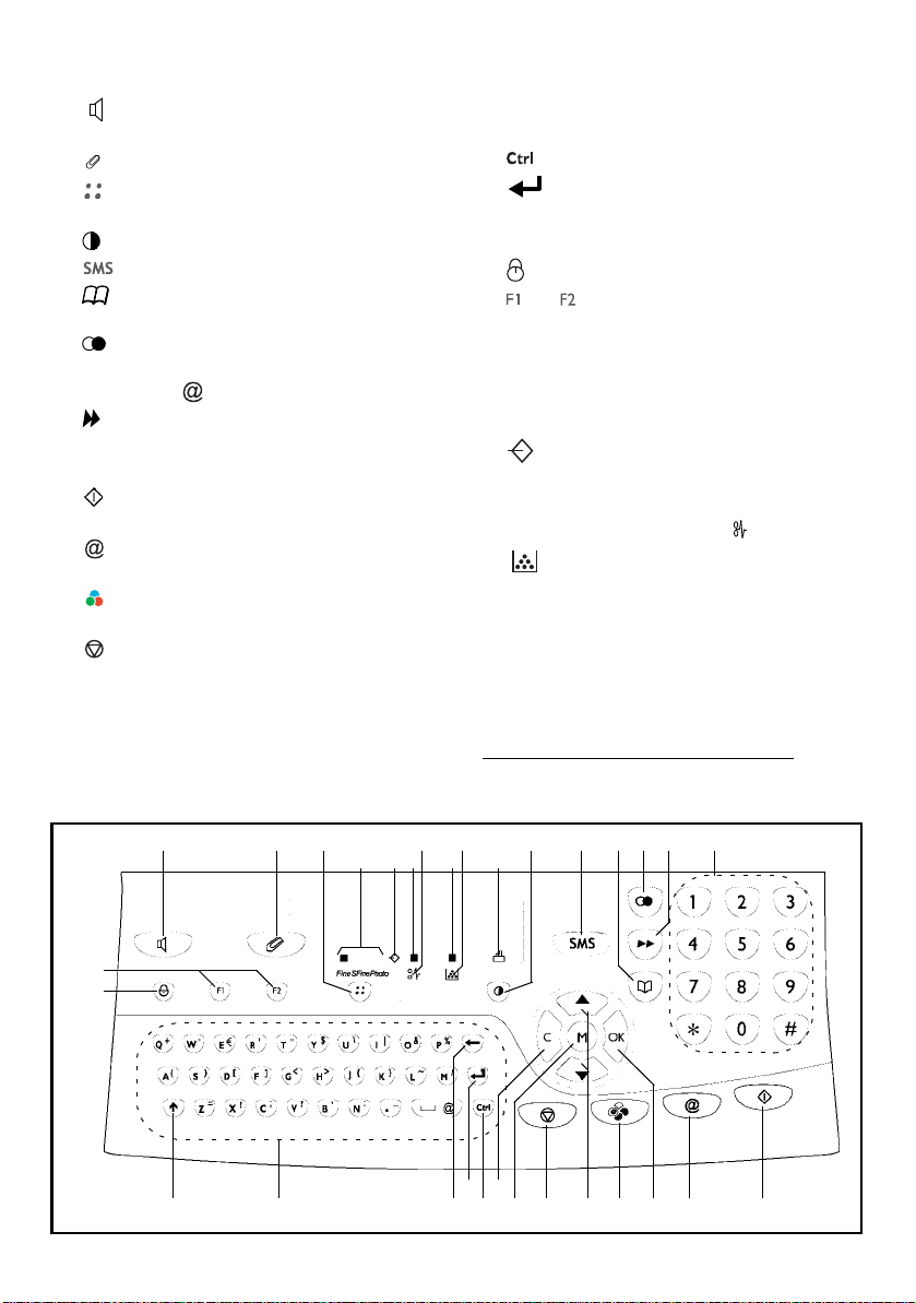
Control panel
1. key: manual line taking, tone monitoring
during fax transmission.
2. key: attachment to a typed-in mail.
3. key: scanning resolution during
transmission or copy.
4. key: contrast adjustment.
5. key: SMS transmission.
6. key: access to directory and quick-dial
numbers.
7. key: access to the last dialled numbers, or
to the last entered e-mail addresses after
pressing the key.
8. key: broadcast transmission (fax, e-mail or
SMS).
9. Numerical keypad.
10. key: fax transmission or black & white
local copy.
11. key: scan to e-mail (Internet fax
transmission).
12. key: colour document transmission over the
Internet.
13. key: stop current operation.
14.M key: access to the different functions
(MENU).
15.OK key: confirm displayed selection.
16.C key: return to previous menu and correct
data entry.
17. and keys: navigation keys.
18.Alphabetical keypad.
19. key: access to special characters.
20. key: enter or go to next line.
21.Í key: erase character before cursor.
22.× key: Shift key.
23. key: Caps lock key.
24. and keys: memorise a key combination.
Default setting:
F1: Scan to PC
F2: Scan to FTP
1
A Scanning resolution during fax transmission
(Fine, SFine, Photo).
B "Line" icon:
On: communication in progress,
Blinking: communication being established.
C Printer Paper Jam indicator .
D "Toner" icon:
On: toner empty,
Blinking: toner near end, toner low.
E Fax reception icon:
* On: reception possible,
* Blinking: unprinted document(s) in memory
or being received,
* Off: reception impossible.
1. Depending on model.
24
23
12
328
BC D EA
29 4 5
20
16
2122
14
6
89
7
1718 19
10111213 15
Page 4

Page 5

1INSTALLATION 1-1
Installing your terminal 1-1
Installation requirements 1-1
Operational precautions 1-2
Unpacking the machine parts 1-4
Description 1-6
Installing the removable parts 1-7
Installing the printer paper tray 1-7
Installing the printer output stacker 1-8
Installing the document feeder for scanning 1-8
Installing the original document output stacker 1-9
Loading paper 1-9
Loading paper manually 1-11
Installing the second paper cassette unit (option) 1-12
Connections 1-14
Telephone and LAN connection 1-15
Power line connection and switch-on 1-15
Installing the Duplex-unit
(depending on model or option)
1-16
Installation Contents
Getting startedDirectoryMaintenanceSafety
2GETTING STARTED 2-1
Navigation methods 2-1
Presentation 2-1
The navigator 2-1
The display screen 2-3
Access to functions 2-3
Menu-driven access 2-3
Direct access by number 2-4
Functions list 2-4
3SETTING YOUR MACHINE 3-1
Remote setting of parameters (depending on the model) 3-1
Embedded web server 3-1
Prerequisites 3-1
Access to the Web server 3-2
Main settings 3-2
Before transmission 3-2
Date/Time 3-2
Your fax number/your name 3-2
Type of network 3-3
Geographical settings 3-3
Local prefix 3-4
Transmission report 3-4
Document feed type 3-5
Economy period 3-5
Before reception 3-5
Fax answering machine 3-5
Reception without paper 3-6
machine
Operation Setting your
-1-
Page 6

Number of copies 3-6
Relay broadcast 3-7
Fax or PC reception (depending on model) 3-7
Technical parameters 3-8
Local Area Network (LAN) settings (depending on model) 3-11
Local network settings 3-11
Automatic configuration 3-11
Manual configuration 3-12
IEEE address (or Ethernet address) or MAC address 3-12
Netbios names 3-12
SNTP server configuration 3-13
Message service and the Internet 3-14
Initialisation parameters 3-14
Access to connection and message service parameters 3-15
Access to servers parameters 3-15
Access to the authentification SMTP parameters 3-15
Settings 3-17
Standard settings 3-17
Mail sorting 3-18
Internet Connection 3-20
Immediate connection to the Internet 3-20
Programmed connection 3-20
Deactivating the Internet function 3-20
SMS service 3-21
SMS Parameters 3-21
Sending an SMS 3-22
Erase an SMS 3-23
SMS Reception 3-23
SMS read 3-23
Print an SMS 3-24
SMS Server 3-24
4DIRECTORY 4-1
Creating subscribers records 4-1
Adding a record 4-2
Creating subscribers lists 4-3
Adding a list 4-3
Adding or deleting a number from the list 4-4
Consulting a record or a list 4-5
Modifying a record or a list 4-5
Deleting a record or a list 4-6
Printing the directory 4-6
Importing a directory 4-6
The file structure 4-7
Procedure 4-8
Exporting a directory 4-9
-2-
Page 7

5OPERATION 5-1
Sending 5-1
Document positioning 5-1
Scanner 5-1
Choosing the resolution/contrast 5-2
Resolution 5-2
Contrast 5-2
Dialling 5-2
From the directory 5-2
From the redial key 5-3
To multiple numbers 5-3
Transmission over the Public Switched Telephone Network (PSTN) 5-4
Immediate transmission 5-4
Delayed transmission 5-4
Transmission with auto redial 5-5
Rerouting 5-5
Tx forwarding 5-6
Transmission over the Internet 5-7
Sending a black and white document to an E-Mail address 5-7
Sending a colour document to an E-mail address 5-7
Sending a typed message to an E-Mail address 5-8
Scan to FTP (depending on model) 5-9
Deposit a file in an FTP server 5-9
Multi-contact sending 5-9
Transmission waiting queue 5-10
Immediately perform transmission from the waiting queue 5-11
Consult or modify the waiting queue 5-11
Deleting a transmission on hold 5-11
Printing a document in waiting or in deposit 5-11
Print the waiting queue 5-11
Cancelling a transmission in progress 5-11
Reception 5-12
Reception over the Public Switched Telephone Network (PSTN) 5-12
Reception over the Internet 5-12
Copying 5-12
Local copy 5-13
Standard copy 5-13
"Sophisticated" copy 5-13
Specific copy settings 5-13
Scanner settings 5-14
Printer settings 5-15
Other functions 5-16
Logs 5-16
Printing the functions list 5-16
Printing the machine settings 5-17
Memorizing a sequence of keys 5-17
To register a sequence (for example, in key F1) 5-17
To send a fax directly to your subscriber (key F1 preset) 5-17
Font printing (depending on model) 5-18
Installation Contents
Getting startedDirectoryMaintenanceSafety
machine
Operation Setting your
-3-
Page 8

Counters 5-18
Deposit and polling 5-18
Placing a document in deposit 5-19
Polling a deposited document 5-19
Lock 5-20
Entering the locking code 5-20
Locking the keyboard 5-20
Locking the numbers 5-21
Locking the Internet settings 5-21
Locking the SMS service 5-21
Scan to PC (depending on model) 5-22
Department code 5-22
Function management by the administrator 5-22
Activating the department code 5-22
Deactivating the department code 5-23
Setting the department codes 5-23
Creating a department code 5-24
Deleting a department code 5-24
Printing a department code 5-25
Printing the department report 5-25
Use of the department codes by a department 5-26
Printing a user department code 5-26
Charge code 5-27
Entering the charge code 5-27
Mail box (MBX FAX) 5-28
MBX management 5-28
Creating an MBX 5-28
Modifying the features of a MBX 5-29
Printing the contents of a MBX 5-29
Deleting a MBX 5-29
Printing the MBX list 5-29
MBX deposit in your fax 5-29
MBX deposit in a remote fax 5-30
MBX polling from a remote fax 5-30
6MAINTENANCE 6-1
Maintenance 6-1
General 6-1
Replacing the consumables (toner and drum) 6-2
Replacing cartridges 6-2
Cleaning 6-15
Cleaning the printer 6-15
Servicing 6-17
Scanner calibration 6-17
Incidents 6-17
Communication errors 6-17
Transmission from the feeder 6-17
Transmission from memory 6-18
Communication error codes 6-18
Printer errors 6-21
-4-
Page 9

Error messages 6-21
Printer paper jam 6-22
Paper jam at the feeders and trays 6-23
Scanner incidents 6-25
Scanner paper jam 6-25
Miscellaneous incidents 6-26
Machine packing and transportation 6-26
Characteristics 6-27
Unit characteristics 6-27
7SAFETY AND ENVIRONMENT 7-1
Installation Contents
Getting startedDirectoryMaintenanceSafety
machine
This unit has been designed in accordance with European standards I-CTR37 and CTR21, it is designed for
connection to the Public Switched Telephone Network (PSTN). In case of any problems, first contact your Supplier.
The mark CE attests that the products comply with the essential requirements of Directive R&TTE 1999/5/EC.
For user safety, in accordance with Directives 73/23/EC.
For electromagnetic interference, in accordance with
The manufacturer declares that the products are manufactured in accordance with ANNEXII of Directive R&TTE 1999/
5/EC.
Directive 89/336/EC.
-5-
Operation Setting your
Page 10

-6-
Page 11
1INSTALLATION
INSTALLING YOUR TERMINAL
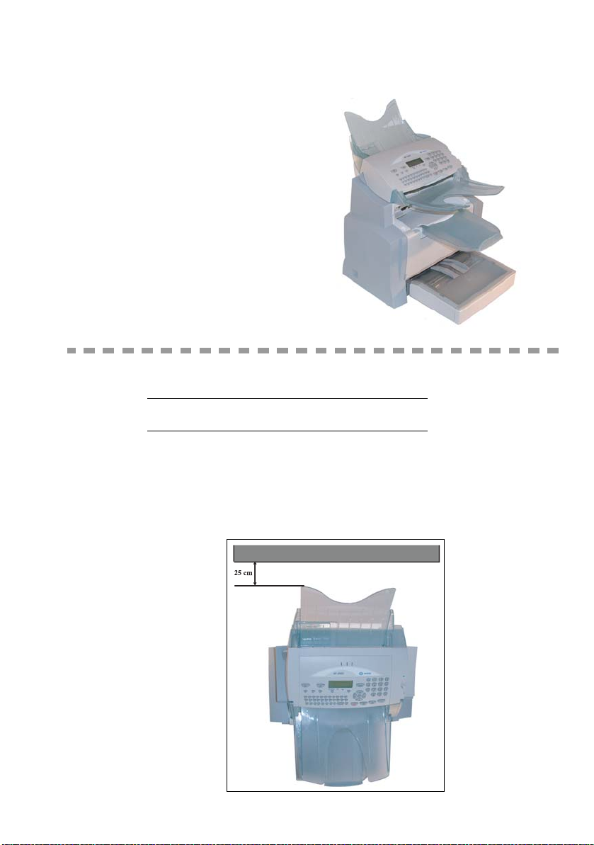
INSTALLATION REQUIREMENTS
A proper location helps to ensure that your printer provides you with the long service life for which
it is designed. Double-check to make sure that the location you select has the following
characteristics:
• Choose a location that is well ventilated.
• When installing the terminal close to a wall, make sure the distance between the wall and the
upper edge of the stacker is at least 25 centimetres for easier opening of the upper cover.
25 cm
1-1
Page 12

• Make sure there is no chance of ammonia or other organic gasses being generated in the area.
• The grounded power outlet (refer to the safety instructions in the Safety Chapter) you plan to co n-
nect to for power should be nearby and not obstructed.
• Make sure that the printer is not exposed to direct sunlight.
• Avoid areas in the direct airflow of air conditioners, heaters, or ventilators and areas subject to
temperature and humidity extremes.
• Choose a sturdy, level surface where the printer will not be exposed to strong vibration.
• Keep the printer away from any objects that might block it s heat vents.
• Do not locate the printer near curtains or other combustible objects.
• Choose an area where there is no possibility of the printer being splashed with water or other liquids.
• Make sure that the surrounding area is clean, dry, and free of dus t.
Operational precautions
Note the following important precautions whenever using the printer.
Operating environment
The following describes the operating environment required when using the printer:
•Temperature:
10°C to 35°C (50°F to 95°F) with fluctuation of 10°C (18°F) per hour.
• Humidity:
20% to 80% (no condensation) with fluctuation of 20% per hour.
Terminal
The following describes precautions for using the terminal:
• Never turn the terminal off or open any of its covers during a print operation.
• Never place flammable gasses, liquids or objects that generate magnetic forces near the terminal.
• When unplugging the power cord, always grasp the plug and never pull on the cord. A damaged
cord creates the danger of fire or electrical shock.
• Never touch the power cord when your hands are wet. Doing so creates the danger of electrical
shock.
• Always unplug the power cord before moving the terminal. Failure to do so can damage the
power cord, creating the danger of fire or electrical shock.
• Always unplug the power cord if you do not plan to use the terminal for a long time.
• Never try to remove any secured panel or cover. The terminal contains high-voltage circuit which
creates the danger of electrical shock when exposed.
• Never try to modify the terminal. Doing so creates the danger of fire or electrical shock.
• Never place any heavy objects on the power cord, pull on it or bend it. Doing so creates the danger of fire or electrical shock.
Installation
1-2
Page 13

Installation
• Always make sure the terminal is not placed on the electrical cord or the communications
cables of any other electrical equipment. Also make sure that cords and cables do not get
into the terminal’s mechanism. Any of these conditions create the danger of malfunction
and fire.
• Always take care that paper clips, staples, or other small pieces of metal do not get into the
terminal through its vents or other openings. Such objects create the danger of fire or electrical shock.
• Do not allow water or other liquids to spill on or near the terminal. Fire or electrical shock
can occur should water or liquid come into contact with the terminal.
• Should liquid or any piece of metal accidently get inside the printer, immediately turn it off,
unplug the power cord, and contact your dealer. Failure to take this immediate action creates
the danger of fire or electrical shock.
• Whenever the terminal emits unusually high amounts of heat, smoke, an unusual odor, or
noise, immediately turn it off, unplug it, and contact your dealer. Failure to take this immediate action creates the danger of fire or electrical shock.
• Paper for printer: do not use paper previously printed by your terminal or any other
printer: the ink or toner deposited on that paper might damage the printing system of
your terminal.
Caution - Be sure to locate the terminal in a well-ventilated location. A minimal amount of
ozone is generated during normal operation of this terminal. Because of this, an unpleasant odor
may result when the printer is used for extensive printing in a poorly ventilated area. For a
comfortable, healthy, and safe operation, be sure to locate the terminal in a well-ventilated area.
Getting startedDirectoryMaintenanceSafety ContentsInstallation
machine
1-3
Operation Setting your
Page 14
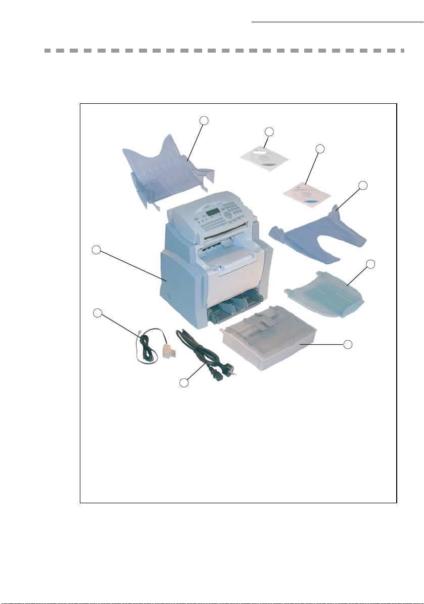
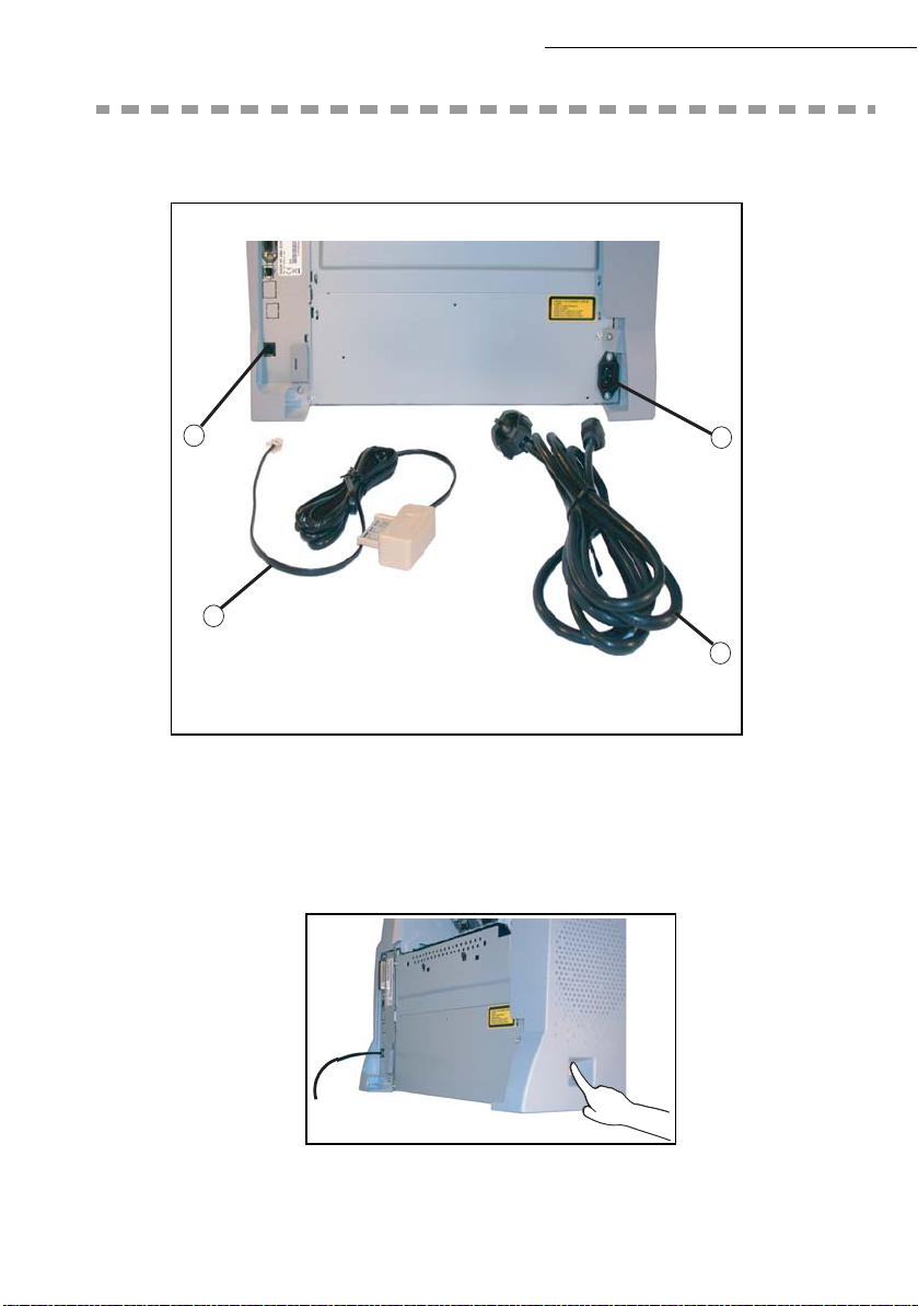
UNPACKING THE MACHINE PARTS
Remove the plastic bags and check for the parts depicted below.
7
9
6
Installation
8
1
2
5
4
1: Scanner output stacker
2: Printer output stacker
3: Printer paper feed tray
4: AC power cord (depending on country)
5: Telephone line cord (depending on
country)
1-4
3
6: Fax/printer terminal
7: Document feed tray for scanning
8: CD-ROM (User Manual)
9: CD ROM Kit Companion Suite
Page 15
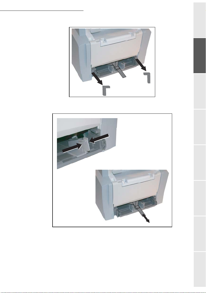
Installation
Pull out the two pads from the paper feed inlet.
Press the paper size guide on the right, in order to push both paper size guides to the left or
to the right. Pull out the plastic tab and the shipping tape from the paper feed inlet.
Getting startedDirectoryMaintenanceSafety ContentsInstallation
machine
Operation Setting your
1-5
Page 16
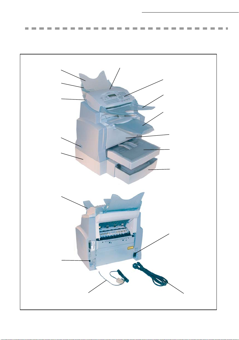
DESCRIPTION
Installation
Document feed
tray for scanning
Adjustable
paper guide
Scanner release
button
On/Off
switch
Second cassette
paper tray
(500 pages)
Chip card
reader
Scanner
Control panel
Original document
output stacker
Printer
output stacker
Printer
Printer paper
feed tray
Second paper
cassette (option)
Telephone line
connector
Phone cord
AC power connector
AC power cord
1-6
Page 17
Installation
INSTALLING THE REMOVABLE PARTS
This section details the installation of the terminal's removable parts.
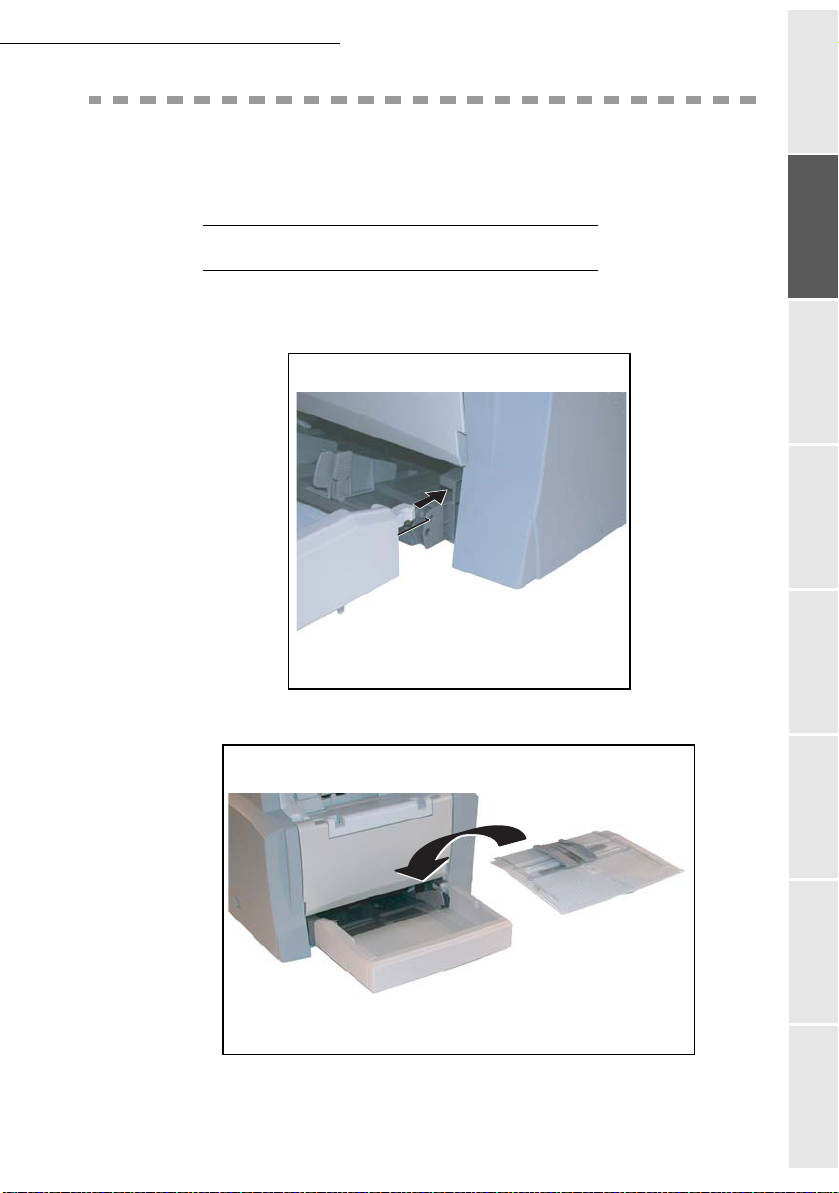
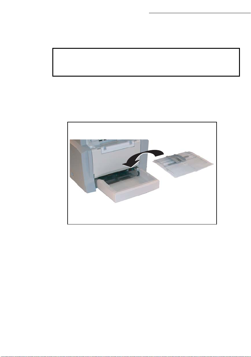
INSTALLING THE PRINTER PAPER TRAY
Using the printer's left and right notches, gently push the tray in until it stops (as illustrated
below).
Getting startedDirectoryMaintenanceSafety ContentsInstallation
machine
Fit the tray cover.
Operation Setting your
1-7
Page 18

Installation
INSTALLING THE PRINTER OUTPUT STACKER
With both hands, slightly bend the centre part of the stacker upwards in order to insert its clips
into the notches located on the upper part of the printer. Release the stacker so that it recovers its
initial shape.
INSTALLING THE DOCUMENT FEEDER FOR SCANNING
Fit the stacker by inserting its two toes into the notches provided at the rear of the terminal.
1-8
Page 19
Installation
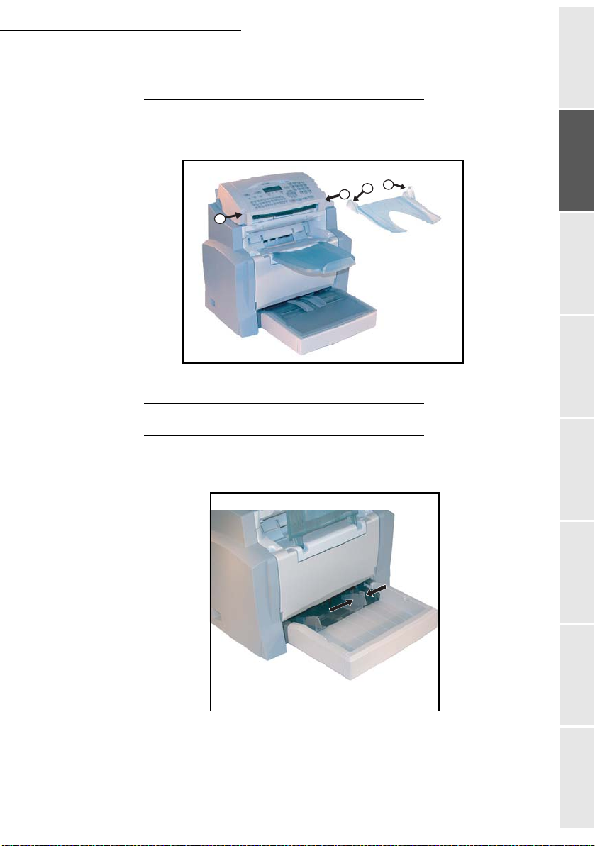
INSTALLING THE ORIGINAL DOCUMENT OUTPUT STACKER
Fit the output stacker on the upper front part of the terminal by inserting its two toes into
the notches provided.
1
2
1
2
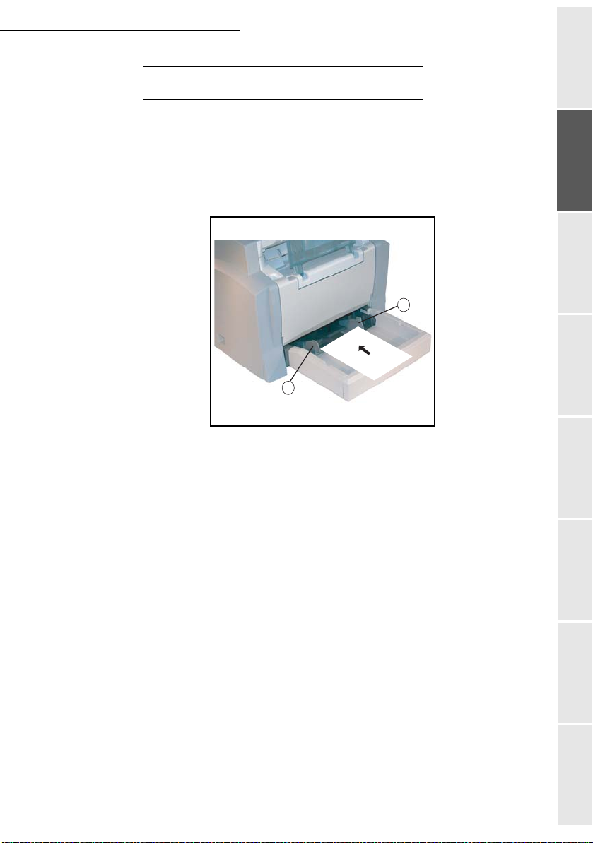
LOADING PAPER
Getting startedDirectoryMaintenanceSafety ContentsInstallation
machine
Press the paper size guide on the right in order to push both paper s ize guides to the left or
to the right.
Place a stack of paper into the tray. In case of letter head paper , be sure to place the pape r
printed side up.
1-9
Operation Setting your
Page 20
Installation
Secure the stack of paper by pushing the paper size guides against the right and left edges of the
stack.
Supported types of paper:
Auto-feed cassette 60 to 90 g/m
Manual feed tray 60 to 160 g/m
2
2
Fit the paper tray cover into place.
Caution - Do not add paper in the paper tray while the machine is printing.
1-10
Page 21
Installation
LOADING PAPER MANUALLY
When printing on special paper, such as 60 to 160 g/m² max. colour paper or transparent film
(laser printer compatible), you should load the paper manually, one sheet after the other. To do so:
Insert your sheet of paper or film between the two feed pawls 1 and 2 located on the paper
tray cover until it stops in the printer.
Adjust the sheet or film width as appropriate by means of feed pawls 1 or 2.
1
2
Getting startedDirectoryMaintenanceSafety ContentsInstallation
machine
Operation Setting your
1-11
Page 22
Installation
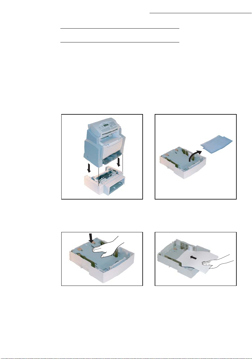
INSTALLING THE SECOND PAPER CASSETTE UNIT (OPTION)
Remove the second paper cassette unit and tray 2 from their packaging, including the
protective tape used to hold the various components in place.
Place the printer on top of the base unit.
Make sure to align the coupling pins of the
base unit with the holes located underneath
the printer.
Press down on the paper lifting plate located
inside of tray 2 until it locks.
Remove the cover from tray 2.
Place a stack of up to 500 sheets of paper
into tray 2 so that the side that was facing up
when the paper was unwrapped is still facing
up.
1-12
Page 23
Installation
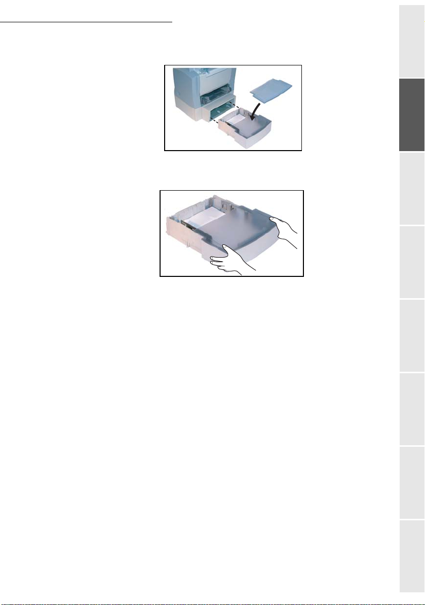
Replace the cassette cover and insert tray 2 into the second paper cassette unit.
Remark: Be sure to use both hands whenever tray 2 is removed from or inserted into the second paper cassette unit.
Getting startedDirectoryMaintenanceSafety ContentsInstallation
machine
1-13
Operation Setting your
Page 24
CONNECTIONS
Installation
A
1
Key to the diagram:
A: Telephone line connector
B: AC power connector
1: Line cord (model depending on country)
2: AC power cord (model depending on country)
Make sure the On/Off switch is set to 0 (Off).
B
2
1-14
Page 25

Installation
TELEPHONE AND LAN CONNECTION
Plug end of the telephone line (1) into the connector on the f ax machine(A), and the other
end into the wall telephone socket.
LAN connection (depending on model). Plug end of the LANcord (as provided by your
network administrator) into port (B) of your fax machine and the other end into your local
network port dedicated to your fax machine.
POWER LINE CONNECTION AND SWITCH-ON
Caution - Refer to safety procedures in the Safety Chapter.
Plug end of the main power cord (2) into the connector (B) on the fax machine, and the
other end in the wall outlet.
Set the On/Off switch to position 1 (On).
After a few seconds, when the printer has warmed up, the date and time will appear.
To set the language and the time of your terminal, refer to paragraph Setting your machine,
page 3-1.
Installing the Duplex-unit
(depending on model or option)
After installation and connection, the duplex-unit will enable you to print, receive faxes or
to receive local photocopies in mode.
Switch off your terminal and pull out the mains plug.
Getting startedDirectoryMaintenanceSafety ContentsInstallation
machine
Operation Setting your
1-15
Page 26
Installation
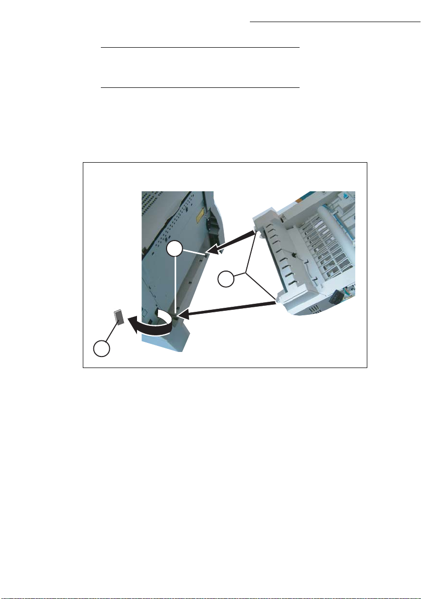
INSTALLING THE DUPLEX-UNIT
(DEPENDING ON MODEL OR OPTION)
After installation and connection, the duplex-unit will enable you to print, receive faxes or to receive
local photocopies in mode.
Switch off your terminal and pull out the mains plug.
Take the duplex unit out of its box and remove the protective film..
C
B
A
Remove the connector cover (A) to obtain access to the connector.
Insert the two plastic clips (B) in the two slots (C) provided for this purpose.
Remark : the insertion of the duplex unit is possible only if you have installed under the terminal a second
paper tray.
1-16
Page 27
Installation
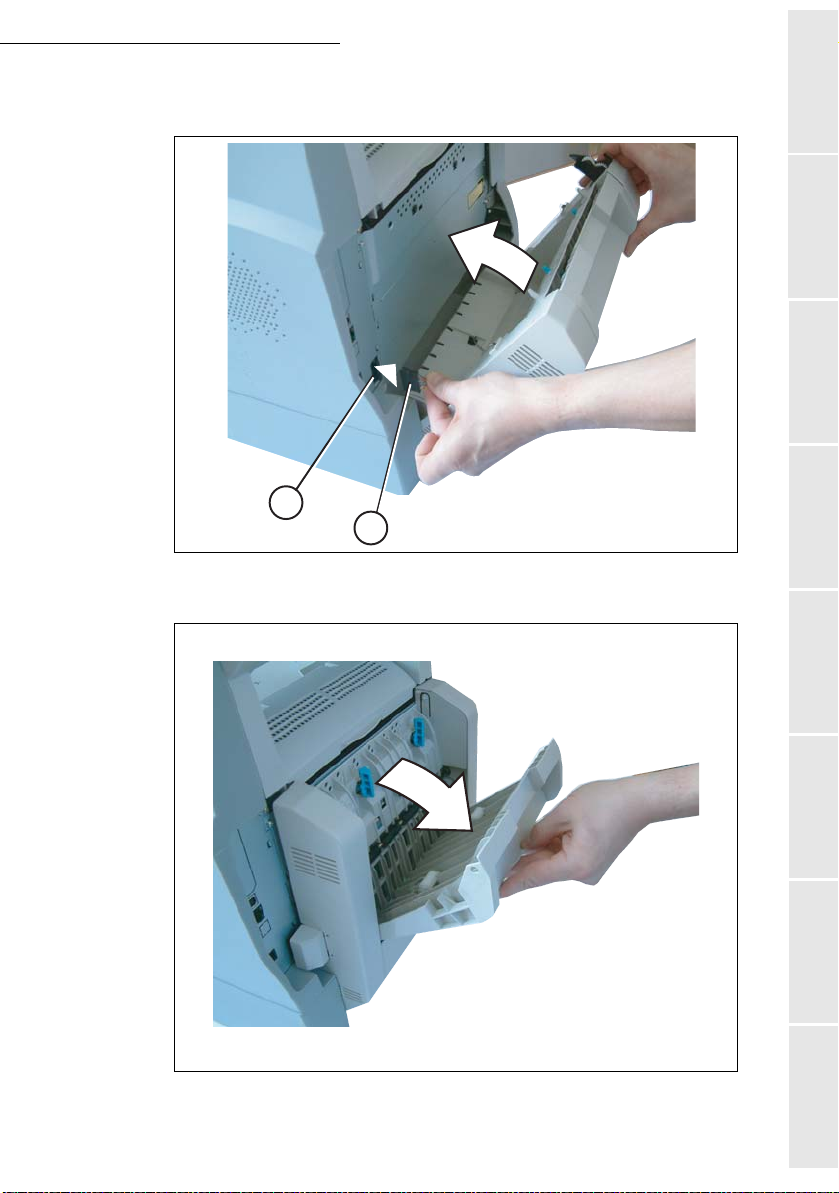
Clip the connector of the flat cable (E) of the duplex unit in the connector (D) located at
the bottom left hand side of the terminal..
D
E
Hold the module in its housing, tip the access door to the two blue-colored locking clips
backwards.
Installation
Getting startedDirectoryMaintenanceSafety Contents
machine
Operation Setting your
17
Page 28
Installation
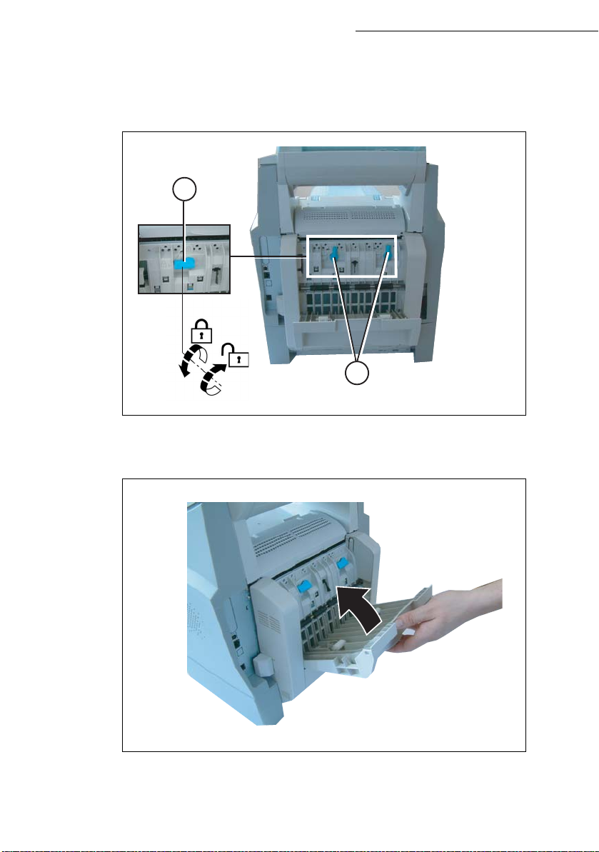
Hold the duplex unit in position and press the two blue colored clips firmly, one after the other,
(A) while rotating them ¼ of a turn clockwise, to lock the duplex unit to the back of your
terminal.
F
F
Once the module is locked in position, close the door. The module is now ready to operate
Reconnect the mains plug and power the terminal using the mains switch located on the left hand
side.
1-18
Page 29
2GETTING STARTED
NAVIGATION METHODS
PRESENTATION
The navigator gives you access to the menus visible on screen.
The navigator
This navigator has 5 keys and allows you to move within the menus available on your machine.
2-1
Page 30
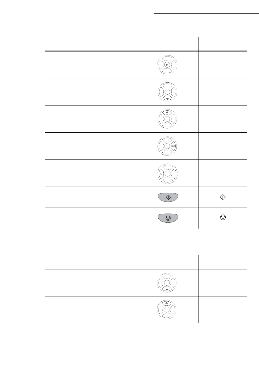
Moving within the menus
To Use key Symbol used
Enter the main menu. M
Getting started
Select the next line in a menu.
Select the previous line in a menu.
Confirm entry and go to the following
menu.
Return to the previous menu. C
Confirm and exit from the current menu.
Exit without confirming from the current
menu.
Moving within a data entry field
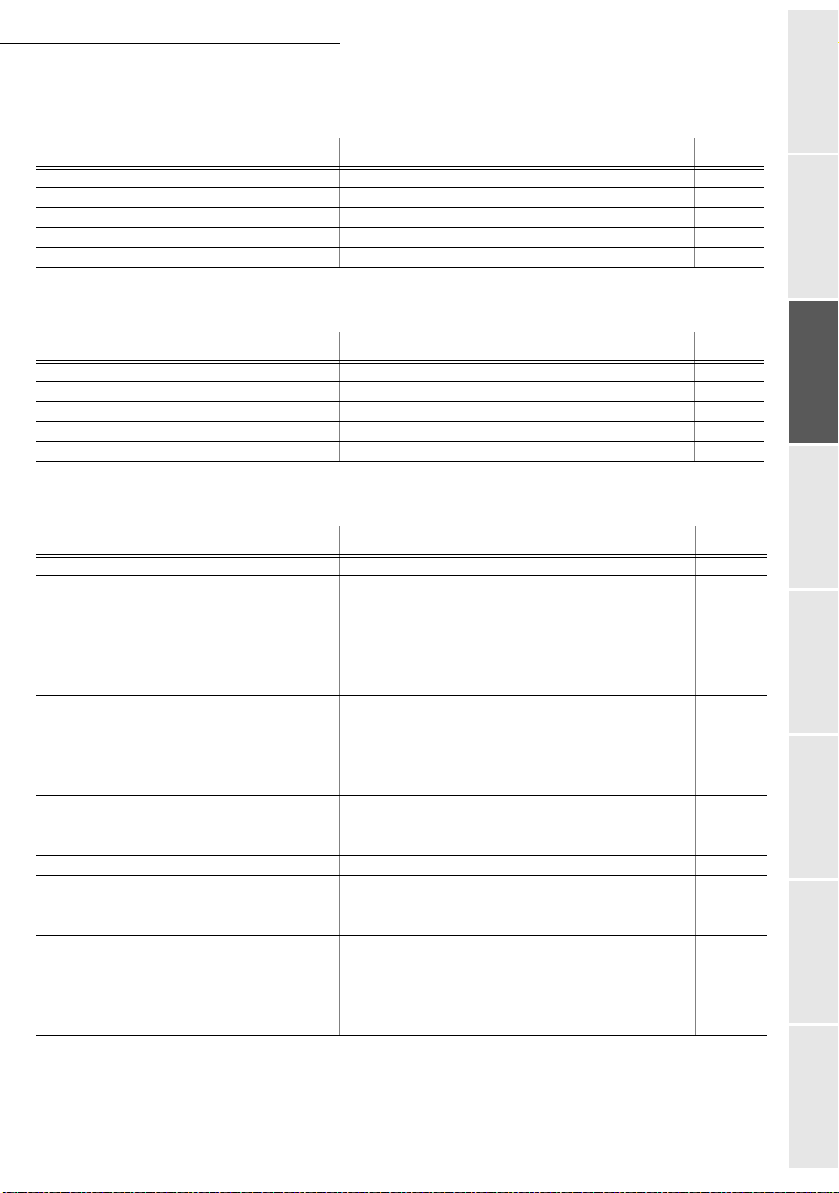
To Use key Symbol used
OK
Move to the right.
Move to the left.
2-2
Page 31

Getting started
To Use key Symbol used
Confirm your entry OK
Delete a character by moving the cursor to
the left.
Confirm your entry and return to the initial
screen.
The display screen
The screen has two lines of 16 characters.
The cursor shows the line you selected.
1DIRECTORY
2 SETUP
For menus with more than two choices, use the arrows
next (hidden) lines of the menu (3, 4, etc.).
ACCESS TO FUNCTIONS
Access to functions may be achieved in two ways.
• Menu-driven access.
• Direct function access.
C
Getting startedDirectoryMaintenanceSafety ContentsInstallation
machine
or of the navigator to obtain the
Menu-driven access
You may print the functions list to know the number of a function.
Press the M key, the functions menu appears.
1DIRECTORY
2SETUP
Use the or navigator arrows to move the cursor in front of the required function.
4SMS SERVICE
5PRINT
Validate your choice by pressingOK.
Operation Setting your
2-3
Page 32

Getting started
When in the selected menu, use the or navigator arrows to move the cursor in front
of the required sub-function.
51 FUNCTIONS LIST
52 LOGS
Validate your choice by pressing OK.
Direct access by number
You may print the functions list (M 51 OK) to know the number of a function.
From the stand-by mode:
Press the M key, enter the number of the required function and validate your choice by
pressing OK.
FUNCTIONS LIST
MAIN MENU 1: DIRECTORY
Functions Function description Page
M 11 OK - NEW CONTACT Enter a name in the directory p. 4-2
M 12 OK
M 13 OK
M 14 OK
M 15 OK
M 16 OK
M 161 OK S
M 162 OK L
M 17 OK
M 18 OK
- NEW LIST Enter a relay broadcast list p.4-3
- MODIFY Modify a record or a list p. 4-5
- CANCEL Delete a record or a list p. 4-6
- PRINT Print the directory p. 4-6
- SAVE/LOAD Store the directory on a chip card
AVE Save the directory to a chip card p. 4-1
OAD Load the directory from a chip card p. 4-1
- IMPORT Enable directory importation by e-mail p. 4-8
- EXPORT Export the directory by e-mail p. 4-9
MAIN MENU 2: SETUP
Functions Function description Page
M 21 OK - DATE/TIME Enter the date and the time p. 3-2
M 22 OK
M 23 OK
M 231 OK S
M 232 OK M
M 233 OK E
M 24 OK
M 241 OK R
M 242 OK N
M 243 OK PC R
- NUMBER/NAME Enter your name and your number p. 3-2
- SEND Transmission settings
END REPORT Choose to print the communication report
p. 3-4
(see M 381 OK)
EMORY SEND Send from feeder or memory p. 3-5
CO PER. Set the economy period (see M 32 OK)p.3-5
- RECEPTION Reception settings
EC. PAPER Accept reception without paper p. 3-6
BR OF COPIE Number of copies of received documents p. 3-6
ECEPT. Choice for PC reception p. 3-7
2-4
Page 33

Getting started
MAIN MENU 2: S
Functions Function description Page
M 25 OK - NETWORKS Network settings
M 251 OK T
M 2511 OK N
M 252 OK P
M 253 OK L
M 2531 OK C
M 2532 OK IP A
M 2533 OK S
M 2534 OK G
M 2535 OK IEEE A
M 2536 OK N
M 2537 OK N
M 2538 OK W
M 2539 OK W
M 254 OK SNTP S
M 2541 OK A
M 2542 OK P
M 2543 OK S
M 2544 OK T
M 2545 OK S
M 29 OK
M 20 OK
M 201 OK C
M 202 OK N
M 203 OK L
EL. NETWORK Telephone network settings
ETWORK TYPE Select the type of network p. 3-3
REFIX Activate the dialling prefix p. 3-4
OCAL NETWORK LAN settings
ONFIGURATION Select the configuration mode p. 3-11
DDRESS IP address of the terminal p. 3-12
UBNET MASK Sub-network mask p. 3-12
ATEWAY Gateway address p. 3-12
DDRESS IEEE address of the terminal (consultation only) p. 3-12
ETBIOS 1 NAME NetBIOS name 1 p. 3-12
ETBIOS 2 NAME NetBIOS name 2 p. 3-12
INS 1 Address of the NetBIOS name server 1 p. 3-12
INS 2 Address of the NetBIOS name server 2 p. 3-12
ERVER SNTP server configuration p. 3-13
DDRESS SNTP server address p. 3-13
ORT SNTP server port p. 3-13
TATE SNTP server state p. 3-13
IME ZONE Time zone p. 3-13
UMMER TIME Adjusting the summer time offset p. 3-13
- TECHNICALS Technical parameters p. 3-8
- GEOGRAPHICAL Geographical settings p. 3-3
OUNTRY The country you select will set the corresponding
network, language and keyboard
ETWORK Set the network individually p. 3-3
ANGUAGE Set the language individually p. 3-3
ETUP
Getting startedDirectoryMaintenanceSafety ContentsInstallation
machine
p. 3-3
MAIN MENU 3: FAX
Functions Function description Page
M 31 OK - TRANSMISSION Single- and multiple-address transmission p. 5-4
M 32 OK
M 33 OK
M 34 OK
M 35 OK
M 36 OK
M 37 OK
M 38 OK
M 381 OK P
M 382 OK A
M 383 OK A
M 39 OK
M 391 OK R
M 3911 OK A
M 3912 OK C
M 3913 OK C
- ECO TRANS. Send a document during the economy period p. 3-5
- POLLING RX Polling request p. 5-19
- POLLING TX Deposit a document p. 5-19
- MBX SENDING Send to a mailbox p. 5-30
- MBX POLLING Poll a mailbox p. 5-30
- BROADCAST Broadcast transmission p. 3-7
- FAX ANSW. Control of fax answering machine p. 3-5
RINT Print fax messages stored in the memory p. 3-6
CTIVATION Activating or deactivating the answering machine p. 3-6
NSWER CODE Saving an access code p. 3-6
- FAX FORWARD. Fax forwarding function
EROUTING Rerouting of received messages p. 5-5
CTIVATION Rerouting activation p. 5-5
ALL NUMBER Choice your destination p. 5-6
OPY Rerouted document local printing p. 5-6
2-5
Operation Setting your
Page 34

Getting started
MAIN MENU 3: F
AX
Functions Function description Page
M 392 OK TX FORWARD. TX forwarding function p. 5-6
M 3921 OK A
M 3922 OK C
CTIVATION TX forwarding activation p. 5-6
ALL NUMBER Recipient selection p. 5-6
MAIN MENU 4: SMS SERVICE
Functions Function description Page
M 41 OK - SEND SMS Send SMS p. 3-22
M 42 OK
M 43 OK
M 431 OK S
M 432 OK SMS
M 433 OK A
M 44 OK
M 45 OK
M 451 OK A
M 452 OK B
M 453 OK S
M 454 OK
M 46 OK
M 461 OK SMS C
M 4611 OK S
M 4612 OK R
M 462 OK SMS C
M 4621 OK R
- READ SMS Read SMS received p. 3-23
- DELETE SMS Delete SMS received
ELECTION Select SMS to delete
READ Delete all SMS read p. 3-23
LL Delete all the SMS read in memory p. 3-23
- PRINT SMS Printing SMS received p. 3-24
- PARAMETERS SMS service / SMS parameters p. 3-21
UTO PRINT Automatically print SMS received p. 3-21
EEP SMS Beep on SMS reception mode p. 3-21
ENDER NAME Choose to show/hide sender name p.3-21
TERM. ADDR. Terminal address p.3-21
- SERVER SMS servers settings p. 3-24
ENTRE 1 Number of main SMS centre p. 3-24
END NO Transmission number p. 3-24
ECEIVE NO Reception number p. 3-24
ENTRE 2 Number of secondary SMS centre p. 3-24
ECEIVE NO Reception number p. 3-24
p. 3-23
p. 3-23
MAIN MENU 5: PRINT
Functions Function description Page
M 51 OK - FUNCTIONS LIST Print the functions list p. 5-16
M 52 OK
M 53 OK
M 54 OK
M 55 OK
M 56 OK
M 57 OK
M 58 OK
M 59 OK
- LOGS Print the communication logs p. 5-16
- DIRECTORY Print the directory p. 4-6
- SETUP Print the settings list p. 5-17
- COMMANDS Print the commands list (see M 65 OK)p.5-11
- LISTE MBX Print the MBX list (see M 75 OK)p.5-29
- PCL FONTS Internal PCL fonts printing p.5-18
- SG SCRIPT FONTS Internal SG Script fonts printing p. 5-18
- DEPART. CODES Print a department code list p .5-26
2-6
Page 35
Getting started
M 61 OK - PERFORM Execute a pending command p. 5-11
M 62 OK
M 63 OK
M 64 OK
M 65 OK
M 71 OK - CREATE MBX Create and modify a MBX p. 5-28
M 72 OK
M 73 OK
M 74 OK
M 75 OK
MAIN MENU 6: COMMANDS
Functions Function description Page
- MODIFY Modify a pending command p. 5-11
- CANCEL Cancel a pending command p. 5-11
- PRINT Print a pending document p. 5-11
- PRINT LIST Print the commands list p. 5-11
MAIN MENU 7: MAILBOXES
Functions Function description Page
- DEPOSIT MBX Deposit a document into a MBX p. 5-29
- PRINT MBX Print the contents of a MBX p. 5-29
- DELETE MBX Delete an empty MBX p. 5-29
- PRT MBX LIST Print the MBX list p. 5-29
MAIN MENU 8: ADVANCED FCT
Getting startedDirectoryMaintenanceSafety ContentsInstallation
Functions Function description Page
M 80 OK - CALIBRATION Scanner calibration p. 6-17
M 81 OK
M 811 OK L
M 812 OK L
M 813 OK L
M 814 OK L
M 815 OK L
M 82 OK
M 821 OK P
M 822 OK S
M 823 OK S
M 824 OK R
M 84 OK
M 841 OK S
M 842 OK P
M 85 OK
M 87 OK
M 871 OK SCAN TO PC Scanned document send to PC application p. 5-22
M 872 OK S
M 88 OK
M 881 OK A
M 882 OK N
M 883 OK C
M 884 OK P
- LOCK Activate an access limitation lock p. 5-20
OCKING CODE Locking co de p. 5-20
OCK KEYBD Activate keyboard lock p. 5-20
OCK NUMBER Activate dialling lock p. 5-21
OCK PARAMET Activate Internet settings lock p. 5-21
OCK SMS Activate SMS lock p. 5-21
- COUNTERS See the activity counters p. 5-18
RINTED PG Printed pages counter p. 5-18
CANNED PAGE Scanned pages counter p. 5-18
ENT PAGES Sent pages counter p. 5-18
ECEIVED PG Received pages counter p. 5-18
- SCAN. & PRINT Scanner and printer settings p. 5-14
CANNER Scanner settings p. 5-14
RINTER Printer settings p. 5-14
- CONSUMABLES Status of consumables p. 6-2
- SCAN TO
CAN TO FTP Scanned document send to FTP server p. 5-9
- DEPT. CODES Setting the department codes
CTIVATION Change the department code settings p. 5-22
EW DEPT. Create or modify a department code p. 5-23
ANCEL Delete a department code p. 5-24
RINT Print a department code list p. 5-25
machine
Operation Setting your
2-7
Page 36

Getting started
MAIN MENU 9: INTERNET
Functions Function description Page
M 91 OK - SUPPLIER Choose the service provider (ISP) p. 3-15
M 92 OK
- INIT PROVIDER
Initialisation of your provider
M 921 OK CONNECTION ISP parameters p. 3-15
M 9211 OK C
M 9212 OK I
M 9213 OK P
M 922 OK M
M 9221 OK I
M 9222 OK P
M 9223 OK E-M
M 923 OK S
ALL NUMB. ISP call number
DENTIFIER ISP identifier
ASSWORD ISP password
ESS. SERV Message service parameters p. 3-15
DENTIFIER Message service identifier
ASSWORD Message service password
AIL ADR Message service e-mail address
ERVERS SMTP, POP3 and DNS parameters p. 3-15
M 9231 OK SMTP SMTP server
M 9232 OK POP3 POP3 server
M 9233 OK DNS 1 Primary DNS
M 9234 OK DNS 2 Secondary DNS
M 924 OK SMTP A
M 9241 OK A
M 93 OK
M 94 OK
- IMMED ACCES
- SETTINGS Internet settings
UTHENT. SMTP authentification access parameters p. 3-15
CTIVATION SMTP authentification activation
Immediate access to ISP
A
M 941 OK CONNEC. TYPE Select connection type p. 3-17
M 942 OK S
M 943 OK P
M 944 OK D
M 945 OK P
M 95 OK
M 96 OK
END TYPE Select transmission type p. 3-18
ERIOD Select the period of connection p. 3-18
EPOSIT NOTI Select to print a deposit notice p. 3-18
RINT Print Internet settings p. 3-18
- E-MAIL Send an e-mail
- SORT MESSAGES Select the reception type
A. These menus will appear only with valid ISPN settings.
A
A
A
A
p. 3-20
p. 5-8
p. 3-18
2-8
Page 37

3SETTING YOUR
MACHINE
The parameters of your unit must be set properly to obtain quality transmission and reception.
You can set the parameters of your unit by browsing through the menus or remotely. The parameters
are set remotely through the embedded web server via a PC registered in the network (depending on
model).
REMOTE SETTING OF PARAMETERS
(
DEPENDING ON THE MODEL)
EMBEDDED WEB SERVER
The same parameters can be set locally or remotely.
Prerequisites
To set your unit remotely, you need:
- A Web browser (Internet Explorer version 4 or higher for optimum operation).
- Define the local network setting parameters of your unit (IP address, sub-network mask...).
Y o ur network administrator will give these parameters to you. When you have this data, refer
to paragraph Local Area Network (LAN) settings (depending on model), page 3-11 in
order to complete the necessary fields.
3-1
Page 38

Access to the Web server
Open a Web browser from a PC registered on the network.
Enter the IP address of the terminal you want to configure in the address field.
Confirm by pressing Enter.
The welcome window is displayed. Select the interface language.
Modify the parameters you want to change on the screen then confirm.
MAIN SETTINGS
At the first power on, set-up the date and time, the network type, the language and check the others
parameters shown hereafter.
BEFORE TRANSMISSION
Date/Time
Setting your machine
At any moment you may change the date and time on your fax machine.
To change the date and time:
Enter the numbers of the required time and date one after another,
(for example November 8 2006 at 9h33, press 0811060933) and press OK to confirm.
Your fax number/your name
Your fax will print out your fax number on each document it transmits if you save this number and if
the machine is set to
To save your fax number and your name:
Enter your fax number (20 digits max.) and pressOK to confirm.
Enter your name (20 characters max) then press OK to confirm.
SENDING HEADER (refer to paragraph Technical parameters, page 3-8).
M 21 OK - SETUP / DATE/TIME
M 22 OK - SETUP / NUMBER/NAME
3-2
Page 39

Setting your machine
Type of network
You may connect your fax to either a PSTN or private network such as private automatic branch
exchange (PABX). You must select the network which is the most convenient.
To select the type of network:
Select option PABX or PSTN then confirm your choice with OK.
Geographical settings
These settings will enable you to use your machine in different preset countries using different
languages.
Country
By choosing a country, you initialise:
• the settings for the public telephone network,
• the language by default.
To select the country:
Select the required option and press the OK key to confirm.
M 2511 OK - SETUP / NETWORKS / TEL. NETWORK / NETWORK TYPE
Getting startedDirectoryMaintenanceSafety ContentsInstallation
M 201 OK - SETUP / GEOGRAPHICAL / COUNTRY
machine
Network
This setting enables you to individually set the type of public telephone network so that your
machine can communicate over the public network of the country you have chosen in compliance
with the applicable standards.
Remark: These settings are different from the NETWORK TYPE (p. 3-3), which allows you to choose between
public and private network.
To select the network:
M 202 OK - SETUP / GEOGRAPHICAL / NETWORK
Select the required option and press the OK key to confirm.
Language
This setting enables you to choose a language other than that imposed by the COUNTRY setting.
To select the language:
M 203 OK - SETUP / GEOGRAPHICAL / LANGUAGE
Select the required option and press the OK key to confirm.
3-3
Operation Setting your
Page 40

Local prefix
This function is used when your fax is installed with a private network, behind a company’s PABX. It
allows you to program an additional automatic local prefix (to be defined), enabling you to
automatically exit the company’s telephone network system, but only under certain conditions:
• the company’s internal numbers, where a prefix is not required, must be short numbers less than
the minimal size (to be defined, for example France has 10 digits),
• the outside numbers requiring a prefix, must be long numbers greater or equal to the minimal size
(to be defined, for example France has 10 digits).
Programming your fax with the local prefix consists of two steps:
• defining the minimal size (or equal) of the company’s outside numbers,
• defining the outgoing local prefix of the company’s telephone network. This prefix will automat-
ically be added as soon as an external number is dialled.
Caution - If you define a local prefix, do not add it to the numbers stored in the directory, it
will be automatically dialled with each number.
Defining the minimal size and the local prefix
You can change the default value for the minimal size of the company’s outside numbers and
validate with OK. The minimal size will range between 1 and 30.
Enter the outgoing local prefix of the company’s telephone network (maximum 5 characters) and
validate with OK.
Setting your machine
M 252 OK - SETUP / NETWORKS / PREFIX
Transmission report
You may print a transmission report for all communications over the telephone network (STN).
You may choose between more than one criteria for printing reports:
WITH: a report is given when the transmission was properly performed or when it is completely
•
abandoned (but there is only one report per request),
• WITHOUT: no transmission report, however, your fax will note all transmissions that took place in
its log (refer to paragraph Logs, page 5-16),
ALWAYS: a report is printed with each transmission,
•
ON ERROR: a report is printed only if the transmission failed or is abandoned.
•
With each transmission report from memory, a reduced version of the first page is automatically
reproduced.
To select the report type:
Select the required option WITH, WITHOUT, ALWAYS or ON ERROR and confirm your choice
with OK.
M 231 OK - SETUP / SEND / SEND REPORT
3-4
Page 41

Setting your machine
Document feed type
You may choose the way you want to feed your documents:
•from memory, transmission will take place only after memory storage of the document and
dialling. It allows you to get your originals back quickly to free up the machine.
•from the feeder of the sheet-feed scanner (refer to paragraph Document positioning,
page 5-1), transmission will occur after dialling. It allows transmission of larger documents
(which size can overtake the memory capacity).
To select the way you want to feed your documents:
M 232 OK - SETUP / SEND / MEMORY SEND
Select the option MEMORY or FEEDER and validate your choice with OK.
Remark: In feeder mode, the reduced image will not appear on the transmission report.
Economy period
This function allows you to defer a fax transmission to "off-peak hours" and thus reduce the cost
of your communications.
The economy period, via the telephone network (at off-peak hours), is preset by default from
7.00 pm to 7.30 am. Nevertheless you may change this time slot.
Modifying the economy period:
M 233 OK - SETUP / SEND / ECO PER.
Enter the hours of the new economy period and confirm your selection withOK.
Using the economy period:
M 32 OK - FAX / ECO TRANS.
Enter the call number and confirm with OK.
Getting startedDirectoryMaintenanceSafety ContentsInstallation
machine
BEFORE RECEPTION
Fax answering machine
The Fax answering machine allows you to keep confidential documents in storage and to avoid
printing them as you receive them.
The "Fax Messages" indicator light lets you know the state of your Fax answering machine:
• Light on: the answering machine is on.
• Blinking: your fax has documents in storage or is in the process of receiving faxes.
• Light off: memory full, the fax cannot receive any more documents.
Operation Setting your
3-5
Page 42

You can assure document confidentiality by using the 4 digit access code. Once saved, you will require
this access code for:
• printing fax messages in memory,
• activate or deactivate the fax answering machine.
Saving an access code
M 383 OK - FAX / FAX ANSW. / ANSWER CODE
Enter the code (4 digits) and confirm with OK.
Activating or deactivating the answering machine
M 382 OK - FAX / FAX ANSW. / ACTIVATION
If you saved an access code for your fax answering machine, enter it and validate with OK.
Select the required option WITH or WITHOUT answering machine and confirm you choice
with OK.
Print fax messages stored in the memory
If you have defined an access code for your fax answering machine, enter it and press OK.
Documents received and stored in the memory are printed.
Reception without paper
Setting your machine
M 381 OK - FAX / FAX ANSW. / PRINT
Your fax offers you the possibility to either accept or refuse document reception if your printer is
unavailable (no paper...).
If your fax printer is unavailable, you may choose between two modes of reception:
• reception mode
• reception mode
To select the reception mode:
WITHOUT PAPER, your fax saves the incoming messages in the memory,
WITH PAPER, your fax refuses all incoming subscribers.
M 241 OK - SETUP / RECEPTION / REC. PAPER
Select the option WITH PAPER or WITHOUT PAPER and confirm your choice withOK.
Remark: Paper out is indicated by a beep and a message on the screen.
Received faxes are then stored in memory (icon "Fax Messages" flashing) to be printed as soon as you add paper
into the feeder.
Number of copies
You may print incoming documents more than once (1 to 99).
To set the number of each document received:
Enter the wanted number of copies and confirm with OK.
At each document reception, your fax will print the number of copies requested.
M 242 OK - SETUP / RECEPTION / NBR OF COPIE
3-6
Page 43

Setting your machine
Relay broadcast
Your fax machine (initiator) can relay a document, in other words, transmit a document to your
subscribers via a remote fax and with a precise relay list.
To do this the initiator fax and the remote fax must both have the relay function.
To relay you need to supply the remote fax with the document and the relay list number. The
remote fax will then transmit this document to all subscribers on the list.
Once the relay is activated by your fax and as soon as the document is received by the remote fax,
the document is printed before relaying to all subcribers on the list.
To activate relay from your fax machine:
The document in the feeder will be relayed either immediately or at a later time (according to your
choice) to the remote fax which will relay the document.
Insert the document to relay (refer to paragraph Document positioning, page 5-1).
Select M 37 OK - FAX / BROADCAST.
Enter the remote fax number where you will relay to or choose your dialling mode (refer
to paragraph Dialling, page 5-2) and press OK.
Enter the relay list number used by the remote fax and press OK.
You may enter the time you wish to transmit the document next to the current time and
press OK.
If you wish to modify the document feed type, select one of the options FEEDER or
MEMORY , then press OK.
If you wish, you may enter the number of pages of your documents before transmitting.
Activate relay by pressing key .
Getting startedDirectoryMaintenanceSafety ContentsInstallation
machine
Fax or PC reception (depending on model)
M 243 OK - SETUP / RECEPTION / PC RECEPT.
This menu, combined with a software program installed on your PC (supplied or on option
depending on model) will enable you to select the machine you wish to receive the documents on:
•fax.
•PC.
• PC if available, fax otherwise.
For more details, please refer to the instruction manual provided with the software kit.
3-7
Operation Setting your
Page 44

Setting your machine
TECHNICAL PARAMETERS
As delivered your fax is preset by default. However, you may adjust it to meet your requirements by
resetting the technical parameters.
To set the technical parameters:
Select the desired parameter and confirm with OK.
With the keys or , modify the parameter settings by following the table below and
press OK.
Parameter Setting Signification
M 29 OK - SETUP / TECHNICALS
1 - SCANNING
MODE
2 - TX HEADER
3 - TX SPEED
4 - ECHO PROTECT
6 - EPT MODE
7 - COM. DISPLAY
8 - ECO ENERGY
10 - RX HEADER
1 - NORMAL
2 - FINE
3 - SFINE
4 - PHOTO
1 - WITH
2 - WITHOUT
1 - 33600
2 - 14400
3 - 12000
4 - 9600
5 - 7200
6 - 4800
7 - 2400
1 - WITH
2 - WITHOUT
1 - WITH
2 - WITHOUT
1 - SPEED
2 - PAGE NUMBER
1 - WITHOUT
2 - DELAY 5 MIN
3 - DELAY 15 MIN
4 - DELAY 30 MIN
5 - STDBY PERIOD
1 - WITH
2 - WITHOUT
Default value of the scan mode resolution for the documents
to be transmitted.
If this parameter is on, your header will appear on all
documents sent to your subscribers with your name , number ,
date and number of pages.
Transmission speed for outgoing documents.
For a quality telephone line (compatible, no echo),
communications occur at maximum speed.
However, it may be necessary to restrict the transmission
speed for some calls.
If this parameter is on, the on-line echo will be reduced during
long distance calls.
For some long distance calls (satellite), the on-line echo may
disturb the call.
Choice between transmission speed displayed or number of
the page in progress.
Choosing the printer standby delay: the printer will switch to
standby after a delay (in minutes) of NON-operation or during
the period of time of your choice.
If this parameter is on, all documents received by your fax
will include the subscriber’s header with his name, number (if
available) fax print date and the page number.
3-8
Page 45

Setting your machine
Parameter Setting Signification
11 - RX SPEED
12 - RINGS
20 - E.C.M.
70 - NET VALID
71 - NET ACTIVE
72 - MODEM SPEED
73 - IMPROVE
REP @
1 - 33600
2 - 14400
3 - 9600
4 - 4800
5 - 2400
2 TO 5
1 - WITH
2 - WITHOUT
06:01 TO 21:59
7 DAYS / WEEK
MON TO FRI
1 - 56000
2 - 33600
3 - 14400
4 - 12000
5 - 9600
6 - 7200
7 - 4800
8 - 2400
9 - 1200
0 - 600
1 - WITH
2 - WITHOUT
Transmission speed for incoming documents.
For a quality telephone line (compatible, no echo),
communications occur at maximum speed.
However, it may be necessary to restrict the transmission
speed for some calls.
Number of rings to automatically start your machine.
This parameter helps correct the calls made on disturbed
telephone lines. It is used when the lines are weak or too
noisy. Transmission times may be longer.
This parameter lets you modify the period when the fax
connects automatically to the Internet.
This menu is available only if the connection type is set to
PERIODIC (M 941).
This parameter lets you select the days of the week when the
fax connects automatically to the Internet.
This menu is available only if the connection type is set to
PERIODIC (M 941).
Choice of maximum Internet transmission speed.
For a quality telephone line (compatible, no echo),
communications occur at the maximum speed.
However, it may be necessary to restrict the transmission
speed for some Internet calls (bad line or bad ISP settings).
This parameter lets you automatically register the Internet
address of your subscribers fax during a call (if available).
Getting startedDirectoryMaintenanceSafety ContentsInstallation
machine
74 - ERASE
MAILBOX
1 - WITH
2 - WITHOUT
When the fax machine receives an e-mail with an attachment
and cannot open it, it erases the message from the ISP MBX,
prints and transmits with a notice of uncomprehension to the
message sender.
At E-mail reception, the fax does not destroy the MBX
message, it prints a notice of uncomprehension asking you
to recuperate this message with your computer equipment.
This parameter is useful only if you have PCequipment. Th e
memory capacity is limited, you need to empty your MBX or
else new messages may not be received.
3-9
Operation Setting your
Page 46

Parameter Setting Signification
Setting your machine
75 - TEXT
ATTACHM.
76 - ATTACHMENT
FORMAT
77 - LAN SPEED
A
A
80 - TONER SAVE
90 - RAW PORT
91 - PRINTER
ERROR TIMEOUT
92 - PRINTER WAIT
TIMEOUT
93 - REPLACE
FORMAT
A
A
A
A
94 - PRINT. CLASS
A. Depending on model or option.
1 - WITH
2 - WITHOUT
1 - IMAGE
2 - PDF
AUTO
100 FULL
100 HALF
10 FULL
10 HALF
1 - WITH
2 - WHITHOUT
9100
30 min
15 seconds
1 - NO
2 - LETTER / A4
A
1 - PC KIT ONLY
2 - PCL/PC KIT
Attachment with or without processing, and printing of
incoming Internet documents.
Default format of document sent on the Internet:
PDF: monochrome or colour.
IMAGE: monochrome (TIFF) or color (JPEG).
To define the communication speed of the peripheral units in
relation to the implemented Local Area Network (LAN).
Makes printing lighter to save toner cartridge ink.
RAW network print port connection.
Time-out before document being printed is deleted following
a print error in PC print mode.
Wait time-out for data from PC before the task is deleted in
PC print.
Page format change.
Printing in GDI mode.
Printing in PCL-/Postscript Mode.
3-10
Page 47

Setting your machine
LOCAL AREA NETWORK (LAN) SETTINGS
(
DEPENDING ON MODEL)
Your terminal is a new generation machine that will be part of your local network just like a PC.
Its built-in local network access card will enable you to send documents through an SMTP/POP3
local message server (internally or externally, depending on the settings of your message server).
To benefit from all the available network options, you should make the following settings,
described in the sections below:
• local network settings, to introduce your fax machine into your local network,
• message service settings, for all your faxes and E-mails to be automatically managed by
your message server.
Caution - Although rather simple, network settings sometimes require a sound knowledge of
your own computer configuration. If that is administrated by anyone in your company, we
recommend you ask that person for the settings described below.
LOCAL NETWORK SETTINGS
Automatic configuration
Getting startedDirectoryMaintenanceSafety ContentsInstallation
machine
We recommend that you carry out a manual configuration of your terminal. The automatic
configuration of the local network settings may be considered, if your local network features a
DHCP or BOOTP server that can dynamically assign addresses to the peripheral devices present
on the LAN.
To automatically configure the local network settings:
M 2531 OK - SETUP / NETWORKS / LOCAL NETWORK / CONFIGURATION
Choose AUTOMATIC and press OK to confirm. The terminal scans the local network for a
DHCP or BOOTP server that can assign it its settings dynamically (the
message
SELF-CONF is displayed).
Once the message SELF-CONF has disappeared, check for the IP Address, Sub-network
mask and Gateway address. If these are missing, you should carry out a manual
configuration (see below).
3-11
Operation Setting your
Page 48

Setting your machine
Manual configuration
To configure your terminal manually, you should obtain the usual information used to set a peripheral
device (IP address, sub-network mask, network and gateway address).
To configure the local network setting manually:
M 2531 OK - SETUP / NETWORKS / LOCAL NETWORK / CONFIGURATION
Choose MANUAL, and press OK to confirm.
IP address
M 2532 OK - SETUP / NETWORKS / LOCAL NETWORK / IP ADDRESS
Enter the IP address of your terminal and pressOK to confirm.
Sub-network mask
M 2533 OK - SETUP / NETWORKS / LOCAL NETWORK / SUBNET MASK
Enter the sub-network mask of your terminal and pressOK to confirm.
Gateway address
M 2534 OK - SETUP / NETWORKS / LOCAL NETWORK / GATEWAY
Enter the IP address of the network gateway and press OK to confirm.
IEEE address (or Ethernet address) or MAC address
The Ethernet card of your terminal already has an unmodifiable, yet consultable, IEEE address.
Netbios names
These names, which can be used with the network options, are used to identify your terminal machine
from a PC connected to a local network (for instance with the name "IMP-NETWORK-1").
Enter the selected name (15 characters max) and press OK to confirm.
The WINS1 and WINS2 servers, used with the network options, allow access to terminals on other
sub-networks by means of their NetBIOS name.
These two addresses must be filled in for the Scan To Disk function.
Enter the IP address of each server, then validate with OK.
M 2535 OK - SETUP / NETWORKS / LOCAL NETWORK / IEEE ADDRESS
M 2536 OK - SETUP / NETWORKS / LOCAL NETWORK / NETBIOS 1 NAME
M 2537 OK - SETUP / NETWORKS / LOCAL NETWORK / NETBIOS 2 NAME
M 2538 OK - SETUP / NETWORKS / LOCAL NETWORK / WINS 1
M 2539 OK - SETUP / NETWORKS / LOCAL NETWORK / WINS 2
3-12
Page 49

Setting your machine
SNTP server configuration
The terminal can automatically update its date and time when connecting to an SNTP server.
Server address
Enter the name of the SNTP server, then validate with OK.
This name can be in the form of an IP address, a DNS address or a NetBIOS name.
M 2541 OK - SETUP / NETWORKS / SNTP SERVER / ADDRESS
Server port
M 2542 OK - SETUP / NETWORKS / SNTP SERVER / PORT
Enter the server port number, then validate with OK.
The port by default is port 123.
Activating the server access
M 2543 OK - SETUP / NETWORKS / SNTP SERVER / STATE
To activate the SNTP server, select WITH in the drop-down menu then validate with OK.
Time zone
M 2544 OK - SETUP / NETWORKS / SNTP SERVER / TIME ZONE
Select the time zone where the terminal is located from the drop-down list then validate
with OK.
If you have activated the automatic summer time management (menu 212), the TIME ZONE
setting is initialised automatically.
Summer time
M 2545 OK - SETUP / NETWORKS / SNTP SERVER / SUMMER TIME
Select the appropriate time setting in the drop-down list: winter time, summer time +1 or
summer time +2, then validate with OK.
Remark: This menu is not displayed if the menu 212 is activated.
Getting startedDirectoryMaintenanceSafety ContentsInstallation
machine
Operation Setting your
3-13
Page 50

Setting your machine
MESSAGE SERVICE AND THE INTERNET
Your terminal lets you send and receive documents and E-mails from subscribers throughout the world
over the Internet.
An E-mail is an electronic message sent over the Internet, to an E-mail address (which is a personal
Internet mailbox).
Access to the Internet is possible thanks to an Internet service provider (ISP). The provider puts at your
disposal a server, or computer system which allows you to connect to the Internet and your mailbox
through your telephone line.
Before worldwide transmission, you must:
• take out an Internet subscription from an Internet Service Provider (ISP),
• check that all initialisation parameters correspond to those provided by your ISP,
• perform the proper settings, if needed, for the Internet connection.
You may then connect yourself to the Internet via your ISP to send and receive fax-Internet or
E-mails. Both operations will be performed during an Internet connection.
INITIALISATION PARAMETERS
You must define or, at least check all parameters needed to identify yourself with the Internet. Your
ISP will provide you with these parameters as soon as you are registered with them.
The parameters are divided in four categories:
• connection, allows you to identify the dial up number, the connection identifier and the connection password,
• message service, allows you to define the message service identifier, the message service password and the E-Mail address,
• servers, allows you to identify the name of the IP address of Internet SMTP providers (send) and
POP3 (MBX reception) and the address of DNS 1 and DNS 2 servers. The server address is made
up of 4 groups of 3 digits maximum, separated by dots,
• SMTP Authentification, used to activate the authentification protocol when the SMTP server
used requests this to end e-mails.
When there is an
of connection and of message service.
OTHER ISP, the server parameters are automatically suggested after the parameters
3-14
Page 51

Setting your machine
Access to connection and message service parameters
M 91 OK - INTERNET / SUPPLIER
Select the Internet provider from the list NO ACCESS, PROVIDER 1, PROVIDER 2,
PROVIDER 3, PROVIDER 4, PROVIDER 5, PROVIDER 6 or LOCAL NETWORK and
press OK.
Choosing
NO ACCESS disables access to Internet functions.
M 921 OK - INTERNET / INIT PROVIDER / CONNECTION
Enter the CALL NUMB., press OK.
Enter connection IDENTIFIER
1
, press OK.
Enter connection PASSWORD, press OK.
M 922 OK - INTERNET / INIT PROVIDER / MESS. SERV
Enter Email IDENTIFIER, press OK.
Enter Email PASSWORD, press OK.
Enter E-MAIL ADR, press OK.
Access to servers parameters
M 923 OK - INTERNET / INIT PROVIDER / SERVERS
Enter SMTP, press OK.
Enter POP3, press OK.
Enter DNS 1 (primary), press OK.
Enter DNS 2 (secondary), press OK.
Getting startedDirectoryMaintenanceSafety ContentsInstallation
machine
Access to the authentification SMTP parameters
M 924 OK - INTERNET / INIT PROVIDER / SMTP AUTHENT.
In the ACTIVATION menu, select WITH to activate SMTP authentification then validate
with OK.
In the PARAMETERS menu, select ID. MESS. SERV to keep the same identification
parameters as in the messaging service or AUTHENT. SPEC. to define other identification
parameters, then validate by pressing OK. When you select AUTHENT. SPEC., carry out the
two following operations:
Enter the IDENTIFIER then validate with OK.
Enter the PASSWORD then validate with OK.
1. If the identifier has more than 16 characters, the text will automatically slide over to the left.
3-15
Operation Setting your
Page 52

Setting your machine
Sample Internet settings for the terminal (56 kbps modem)
Your access provider should give you the following information:
CALL NUMBER: 0860001000
CONNECTION IDENTIFIER: sg048944@wn.net
CONNECTION PASSWORD: *****
MESSAGE SERVICE IDENTIFIER: demo jt12
MESSAGE SERVICE PASSWORD: *****
E-MAIL ADDRESS: demo2@gofornet.c om
SERVER:
SMTP mail.gofornet.com
POP mail.gofornet.com
DNS 1 103.195.014.001
DNS 2 103.195.014.002
Non-functional data given by way of example.
You should then complete the following MENUS on your fax machine:
91 SUPPLIER PROVIDER 1
CONNECTION
9211 CALL NUMB. 0860001000
9212 IDENTIFIER sg048944@wn.net
9213 PASSWORD *****
MESSAGE SERVICE
9221 EMAIL ID demo jt 12
9222 EMAIL PASSWORD *****
9223 E-MAIL ADR demo2@gofornet.com
SERVERS
9231 SMTP mail.gofornet.com
9232 POP3 mail.gofornet.com
9233 DNS 1 103.195.014.001
9234 DNS 2 103.195.014.002
3-16
Page 53

Setting your machine
Your terminal is now configured. Print the settings in order to check they have been
acknowledged by pressing M, 9, 4, 5 and OK.
The settings are divided into several categories:
•the standard settings define the connection type and frequency to the Internet as well as the
•the E-mail sorting defines treatment for all stored E-mail messages received.
Standard settings
SMTP AUTHENT.
9241 ACTIVATION With or Without
SETTINGS
transmission type for your documents,
Getting startedDirectoryMaintenanceSafety ContentsInstallation
Your machine has two types of settings that let you define:
• the type and frequency of the connection to your ISP.
SET TIMES
PERIODIC
ON DEMAND
1. To avoid Internet access saturation, the automatic connection will occur in reality 12 minutes,
give or take, around the requested time.
• the type of transmission over the Internet.
IMMEDIATE
DURING
CONNECTIONS
At any moment you may print the settings of your machine to know their status.
An Internet connection is established every day at
9:00 am, 12:30 am and 5:00 pm
An Internet connection is established every 3 hours1.
(default value)
An Internet connection is established at your request by
IMMED. ACCESS (refer to paragraph Internet
Connection, page 3-20)
Document transmission will occur immediately at each
transmission request
Transmissions will only occur at programmed
connections
SET TIMES or PERIODIC TYPE
1
Selecting the connection type
M 941 OK - INTERNET / SETTINGS / CONNEC. TYPE
Select one of the connection options among SET TIMES, PERIODIC or ON DEMAND and
press OK to confirm.
machine
Operation Setting your
3-17
Page 54

Setting your machine
Changing the connection period (PERIODIC type)
M 943 OK - INTERNET / SETTINGS / PERIOD
With the PERIODIC mode, enter the new connection period by means of the numerical keypad
(between 00:01 am and 11:59 pm) and press OK to confirm.
An Internet connection will be established every three hours (default value).
Changing the connection times (SET TIMES type)
M 943 OK - INTERNET / SETTINGS / TIME
With the SET TIMES mode selected, use the or key to place the cursor under the numeral
you want to change. Enter the new connection time(s) by means of the numerical keypad
(between 00:01 am and 11:59 pm) and press OK to confirm.
Selecting the transmission type
M 942 OK - INTERNET / SETTINGS / SEND TYPE
Select one of the transmission options IMMEDIATE or DURING CNX and press OK to confirm.
Selecting the print mode for the deposit notice
M 944 OK - INTERNET / SETTINGS / DEPOSIT NOTI
Select one of the deposit notice options WITH, WITHOUT, ALWAYS or ON ERROR and press OK
to confirm.
Printing the Internet settings
M 945 OK - INTERNET / SETTINGS / PRINT
The Internet settings are printed.
These settings may also be printed together with all the other settings of your machine (refer to
paragraph Printing the machine settings, page 5-17).
Mail sorting
This function lets you choose the mode for all Internet documents stored in your mail box.
You have three choices:
•
F@X ONLY, lets you poll and print E-Mails in your machine.
PC ONLY, lets you keep your E-Mails in you mailbox for later use with a computer (no E-Mail
•
poll),
• SHARE PC lets you:
- if your PC and fax have two differen t addresses, transfer all mails or only those with attachments
to a PC,
- if your PC and fax share the same address, use the fax as a printer for E-Mails for the PC.
M 96 OK - INTERNET / SORT MESSAGES
3-18
Page 55

Setting your machine
F@X Only mode
PC Only mode
Share PC mode
Select option F@X ONLY and press OK to confirm.
All E-Mails are polled and printed.
Select option PC ONLY and press OK to confirm.
The E-mails are neither polled nor printed and they may be used with a computer.
At each connection, the number of E-mails in your mailbox is displayed on the screen.
Select option SHARE PC and press OK to confirm.
You may choose to transfer your E-mails to a PC or use the fax as an E-mail printer.
To transfer the E-Mails to a PC:
Select option WITH PC TRANS. and press OK to confirm.
Enter the E-Mail address of the computer you wish to transfer your E-Mail and press OK
to confirm.
Select your option from the table below and press OK to confirm.
Menu Description
Getting startedDirectoryMaintenanceSafety ContentsInstallation
machine
SEND ALL MAILS All E-Mails are sent to the PC.
UNUSABLE ATTAC
To use the fax as an E-Mail printer:
The fax machine polls and prints the usable E-mails and transfers to
the PC mailbox all the E-mails containing attachments it cannot use.
Select option W/O PC TRANS and press OK to confirm.
Select your option from the table below and validate with OK.
Menu Description
DELETE MAILS
SAVE MAILS The E-mails opened and read by the fax are not erased.
At each connection, the number of E-mails still present in your mailbox are displayed on the
screen.
The E-mails opened and read by the fax (w/o attachment) are erased
after the fax has printed.
3-19
Operation Setting your
Page 56

INTERNET CONNECTION
An Internet connection is made with an ISP. It allows both document sending and reception while
connected.
A connection takes place the following way:
• Send to one or more of your subscriber’s Internet mailboxes, all fax-Internet documents waiting
for transmission.
If you are sending to a computer, the transmitted fax will be received as an attachment to an
E-Mail.
• Reception of all fax-Internet and E-Mails deposited in your personal Internet mailbox.
You may connect either immediately or automatically depending on the time periods defined. The
triggering of a programmed Internet connection depends on the standard settings of your machine.
Immediate connection to the Internet
There are two methods to immediately connect to the Internet:
Access through the menu:
Direct access:
Press the key twice.
Setting your machine
M 93 OK - INTERNET / IMMED ACCES
Programmed connection
An automatic connection to the Internet depends on how your machine is programmed and more
particularly on the standard settings (refer to paragraph Standard settings, page 3-17).
DEACTIVATING THE INTERNET FUNCTION
If you do not wish to use the Internet functions:
Select NO ACCESS in the ISP list and confirm with OK.
M 91 OK - INTERNET / SUPPLIER
3-20
Page 57

Setting your machine
SMS SERVICE
Thanks to the button you can send an SMS to subscribers all over the world. An SMS (Short
Message Service) is a service which permits short written messages to be sent to mobile phones
or other SMS-compatible devices.
The number of characters you can send per messag e is dependent upon the service provider and
the country you are sending your SMS from (e.g. France 160 characters, Italy 640 characters).
The SMS service is dependent upon the country and the service provider.
Caution - There is a special scale of charges for the SMS service.
This menu is used to set several options:
• automatic SMS print on reception,
• beep activated during SMS reception,
• send your details activated,
• the address of your terminal.
The address is only modified if several terminals are installed on your line. It is used to
differentiate between two machines during SMS reception.
When you want a contact to send SMSs to the terminal you choose, you must send him your line
number and the destination terminal address.
If your contact does not add the address of the terminal, the SMS will be received in the terminal
with address 0.
Automatic print of SMS received.
Select the option WITH or WITHOUT automatic print, then validate with OK.
Beep activated on SMS reception.
Select the option WITH or WITHOUT beep on reception, then validate with OK.
Presentation of SMS sender.
Select the option WITH or WITHOUT presentation of the sender, then validate with OK.
Terminal address.
Enter the terminal number, then validate with OK.
SMS PARAMETERS
M 45 OK - SMS SERVICE / PARAMETERS
M 451 OK - SMS SERVICE / PARAMETERS / AUTO PRINT
M 452 OK - SMS SERVICE / PARAMETERS / BEEP SMS
M 453 OK - SMS SERVICE / PARAMETERS / SENDER NAME
M 454 OK - SMS SERVICE / PARAMETERS / TERM. ADDR.
Getting startedDirectoryMaintenanceSafety ContentsInstallation
machine
Operation Setting your
3-21
Page 58

Setting your machine
SENDING AN SMS
To send an SMS to any SMS-compatible devices:
Press the key.
Write your SMS by means of the Qwerty keypad.
To do so, you have a true editor at your disposal:
•for the upper case letters, use the
•to move inside the data entry field, use the or keys,
•to move in the text from one word to another, press the C
•to go to the next line, use the key,
•to delete a char acter (by moving the cursor to the left), use the Í or C key.
Press to confirm your entry.
Dial the number of the recipient (mobile phone or any other SMS-compatible device) in one of
the following ways:
• dial the number by means of the numerical keypad,
• enter the first letters of the recipient name,
• press the key until the required name appears (names are classified in alphabetical order),
• press the key to display the required name. The screen displays the last person you have sent
an SMS to, use the
or keys to select a different number.
Your SMS may be sent to only one person or to several people. To send an SMS:
× key or key,
TRL key and one of the navigator keys,
• to only one person, press the key to confirm,
• to several people:
- press the key and enter the next person's name,
- repeat the operations as many times as required (10 persons max.). Press the key to
confirm.
SENDING SMS is displayed as the SMS is being sent.
SENDING SMS is no longer displayed, the SMS has been sent and th e recipient nu mber is saved
Once
(key).
• If SMS appears, then the SMS has been put on hold and a further attempt will take place a couple
of minutes later. To immediately execute or cancel transmission, refer to paragraph Transmission
waiting queue, page 5-10.
• To check the SMS has been sent properly, you may print the transmission/reception log
(M 52 OK - PRINT / LOGS, p. 2-6).
3-22
Page 59

Setting your machine
ERASE AN SMS
Proceed as follows to erase an SMS:
M 43 OK - SMS SERVICE / DELETE SMS
Select the messages to erase.
M 431 OK - SMS SERVICE / DELETE SMS / SELECTION
Select SELECTION using keys and and validate with OK.
Select a message using keys and and validate with OK.
Erase messages already read.
M 432 OK - SMS SERVICE / DELETE SMS / SMS READ
Select MESSAGES READ using keys and and validate with OK.
Confirm with OK.
Erase all messages from memory.
M 433 OK - SMS SERVICE / DELETE SMS / ALL
Select ALL using keys and and validate with OK.
Confirm with OK.
Getting startedDirectoryMaintenanceSafety ContentsInstallation
machine
SMS messages received are automatically printed (you can modify this setting with M 451 OK
- AUTO PRINT). If you disable automatic printing, the messages are automatically stored in the
memory.
SMS read
Access by menus:
• Direct access:
Press key.
Select READ SMS using keys and and validate with OK.
Select a message using keys and and validate with OK.
Scroll messages using keys and .
SMS RECEPTION
M 42 OK - SMS SERVICE / READ SMS
3-23
Operation Setting your
Page 60

Print an SMS
Access by menus:
• Direct access:
Press key.
Select PRINT SMS using keys and and validate with OK.
Select SELECTION (to choose messages to print), NEW (to print all unread messages) or ALL
(to print all messages in memory) using keys
Confirm with OK.
This menu is used to set the transmission and reception numbers of your SMS centers. They will be
provided by your access provider. You can define two SMS centres, one main and one secondary. The
secondary centre may only be used for SMS reception.
Access to server mode:
Define SMS Centre 1 numbers:
Setting your machine
M 44 OK - SMS SERVICE / PRINT SMS
and and validate with OK.
SMS SERVER
M 46 OK - SMS SERVICE / SERVER
M 461 OK - SMS SERVICE / SERVER / SMS CENTRE 1
Define send number:
M 4611 OK - SMS SERVICE / SERVER / SMS CENTRE 1 / SEND NO
Enter the send number of your main SMS centre, then validate with OK.
Define reception number:
M 4612 OK - SMS SERVICE / SERVER / SMS CENTRE 1 / RECEIVE NO
Enter the reception number of your main SMS centre, then validate with OK.
Define SMS Centre 2 numbers:
M 462 OK - SMS SERVICE / SERVER / SMS CENTRE 2
Define reception number:
M 4621 OK - SMS SERVICE / SERVER / SMS CENTRE 2 / RECEIVE NO
Enter the reception number of your secondary SMS centre, then validate with OK.
3-24
Page 61

4DIRECTORY
Your fax lets you create a directory by memorising subscriber records and subscriber lists.
• Your machine can store up to 500 subscriber records with names and phone numbers.
• You may also group several names to build a subscriber list with up to 32 subscriber lists.
A subscriber list is made from the subscriber records already stored.
For all subscriber records or subscriber lists you may:
• create,
• consult,
• modify contents,
• delete,
• print the directory.
CREATING SUBSCRIBERS RECORDS
For each subscriber record you are not required to fill in each line, only name, tel or E-Mail address
are required:
•
NAME of your subscriber,
TEL, and fax number of your subscriber,
•
E-MAIL address, example: jones@address.com.
•
or
• FTP address, example: 134.1.22.9,
• If you have not entered an E-MAIL adress, you can enter a FTP adress (to store data),
• FORMAT: by default, the attachment is PDF or Image (.tiff or .jpeg),
4-1
Page 62

• RECORD NO., this number is automatically assigned by the fax, it allows quick access to the
answering machine,
•
RATE for each subscriber you may c hoose your fax transmission speed. The available rates are
2400, 4800, 7200, 9600, 12000, 14 400 and 33 60 0 bits p er s eco nd. W ith a g ood teleph one co nnection, well adapted and without echo, the appropriate rate is the highest one.
If your subscriber number has both
determine if the document will be sent over the telephone network or over Internet.
TEL and E-MAIL listed, the validation key ( or ) will
ADDING A RECORD
Your fax has just created a new record, fill in it by first entering your subscriber’s name then
validate with OK.
Remark: You can stop the list creation at any time by pressing .
Enter the person’s fax number
Enter the E-Mail address of your subscriber and pressOK to confirm.
Your subscriber’s ID number will automatically appear on the screen, if you wish to modify this
number you may do so by choosing another free number and validate with OK.
Select the option WITH assigned key if you want to assign a letter (shortcut key) to your
subscriber. The first available letter appears by default. If you want to change it, scroll the letters
by means of the
or keys, and press OK to confirm.
If need be, select the appropriate transmission speed to send your faxes, and confirm your choice
by pressing OK.
or to associate an FTP address:
Do not enter the e-mail address.
Enter the FTP address of the contact, then validate with OK (for example: 134.1.22.9).
Enter the FTP user name (for example: Jones).
Enter the password of the FTP user.
If necessary, enter the file destination directory (when this field is not completed, the files are
stored directly under the root) of the FTP server (for example: server name / Jones).
Define the attachment format (Image or PDF), then validate with OK.
1
and press OK to confirm.
Directory
M 11 OK - DIRECTORY / NEW CONTACT
1. If your machine is connected to a PABX, you may need to insert a pause for dial tone (symbolised by the sign/ in the
number) except if a local prefix is already programmed (see § Local Prefix)
4-2
Page 63

Directory
A number allocated to your contact will be automatically displayed on the screen. If you
do not want to use this number, it can be modified by entering another number, then
validating with OK.
Select the option WITH the associated key if you want to associate a letter (shortcut key)
with your contact. The first letter free is displayed by default. If you want to modify this,
scroll through the alphabet by using keys
Select, if necessary, the appropriate send rate for a fax intended for your contact, then
validate your choice with OK.
CREATING SUBSCRIBERS LISTS
A subscriber list is made from the subscriber records already stored.
For each list fill in the following lines:
NAME of the list,
•
NUMBER ASSIGNED to the list, this number is automatically assigned by the fax. It allows
•
quick access to the answering machine,
•
LIST COMPOSITION, its lists the ID numbers assigned to the subscribers records included in
the list,
• LIST NUMBER, a number lets you identify the list filed under (L).
A list may include both fax and internet subscribers.
The same subscriber may be included in different lists.
Caution - It is impossible to add one subscriber list to another subscriber list.
or , then validate your choice with OK.
Getting startedDirectoryMaintenanceSafety ContentsInstallation
machine
ADDING A LIST
To add a list:
M 12 OK - DIRECTORY / NEW LIST
Your fax machine has just created a new list, fill it in by first entering the name of this list
then confirm with OK.
Remark: Y ou can stop a list or record creation at any time by pressing . Also, you do not have to complete all the
list characteristics as you create it; you can save the list as it is by pressing .
The empty field SUBSCRIBER 1 appears, you must fill in the ID numbers assigned to the
subscriber records included in this list.
4-3
Operation Setting your
Page 64

Directory
There are three ways detailed in the table below, to choose and add one or more subscribers to
your list. Then confirm your choice by pressingOK.
From ... Procedure
subscriber’s name
subscriber’s ID number
subscribers directory
letters of your subscriber’s name and continue
until the whole name is displayed on the screen.
Enter directly the subscriber’s ID number.
Press key then select by means of the
or keys.
For every subscriber included in the list repeat the above step then validate with OK.
With the alphanumeric keypad enter the first
Remark: You can stop record creation at any time by pressing .
The list ID number will automatically appear on the screen, if you wish to modify this number
you may do so by choosing another free number and validate with OK.
Press to confirm your entry.
ADDING OR DELETING A NUMBER FROM THE LIST
M 13 OK - DIRECTORY / MODIFY
Select the subscriber list (L) by means of the or keys and validate your choice with OK.
4-4
Page 65

Directory
Press OK to display the SUBSCRIBER 1 field, and add or delete the subscriber as shown
in the table hereafter:
To ... Procedure
Enter the subscriber ID number you wish to add and confirm
add
with OK.
Repeat this step for each added subscriber you want to add.
Place the keys or , on the number you wish to delete.
delete
Press key C to delete the number assigned to the list.
Repeat these 2 steps for each subscriber you wish to delete from
the list.
Confirm the new list by pressing key .
CONSULTING A RECORD OR A LIST
Press key .
The directory appears in alphabetical order.
Select the subscriber record or subscriber list (L) you wish to consult.
MODIFYING A RECORD OR A LIST
M 13 OK - DIRECTORY / MODIFY
The directory appears in alphabetical order.
Use the or keys to select the subscriber list (L) you wish to modify and press OK
to confirm.
Modify the line or lines in the subscriber record or subscriber list and confirm each
modification with OK.
Remark: You may confirm your modification by pressing key , but you will exit the menu and may not be able
to modify the following lines.
Getting startedDirectoryMaintenanceSafety ContentsInstallation
machine
Operation Setting your
4-5
Page 66

DELETING A RECORD OR A LIST
M 14 OK - DIRECTORY / CANCEL
The directory appears in alphabetical order.
Use the or keys to select the subscriber record or subscribers list (L) you wish to delete
and confirm with OK.
Press again OK to confirm your deleting.
The record or list is deleted from the directory.
PRINTING THE DIRECTORY
You may print all the numbers stored in the directory, including all the existing subscriber records or
subscriber lists.
To print the directory:
M 15 OK - DIRECTORY / PRINT
The directory is printed in alphabetical order.
Directory
IMPORTING A DIRECTORY
You can import an existing directory of contacts into your fax machine as an electronic file. This file
must be in a specific format and must not comprise more than 250 entries.
The process of importing a directory uses electronic mail as the transfer mechanism. The electronic file
containing the directory is received and processed as an e-mail attachment.
Caution - Importing a new directory completely overwrites any existing directory entries.
4-6
Page 67

Directory
THE FILE STRUCTURE
The electronic file containing the data in the directory must be structured into lines or records
each comprising five fields separated from one another by a unique character (a tab stop, a
comma or a semi-colon). The lines themselves are separated by a line break (carriage return).
Fields Contents
Name
Fax number
E-mail
address
Shortcut
key
Speed
A unique identifier in your directory, up to 20 characters long. This field is
mandatory; the name should not include the field separator character.
Your contacts’ fax number, without spaces or dots, can be up to 30 characters
long (including any * and # characters). This field may be left empty, for
instance, in the case of contacts to whom you only send e-mails.
Your contacts’ e-mail address. Can be up to 80 characters long, but must not
comprise the field separator character. Any other characters may be used in this
field, which can also be left blank.
A capital letter (A to Z), unique to the directory, which is associated with a
specific contact and enables quick selection. As with the two previous fields,
this field can be left blank.
The fax transmit speed over the PSTN. If you do not specify a value, the default
speed is the maximum speed. This field may be left blank if all your fax
transmissions are handled by a fax server.
Caution - You must enter a value for at least one of the Fax number or E-mail address fields.
To enter a blank line, key in four field separator characters in a row.
For example:
Smith;0123456789;jsmith@isp.co.uk;J;8
Jones;01987654321;;@;8
Getting startedDirectoryMaintenanceSafety ContentsInstallation
machine
Operation Setting your
O'Connor;0123469874;d.oconnor@hello.net;U;8
Remark: @ alone is the indication that no associated key is assigned to the entry.
4-7
Page 68

Directory
The rate is coded on a number, see the following board:
Rate Code number
600 7
1200 6
2400 5
4800 4
7200 3
9600 2
12000 1
14400 0
33600 8
Caution - You must always enter the field separator character, even if one or more of the fields are
left blank. In the example above, which uses a semi-colon as a separator, the entry for « Jones » lacks
both E-mail address and shortcut key.
PROCEDURE
To import a directory:
M 17 OK - DIRECTORY / IMPORT
Select WITH to authorise the importation of a directory.
Create your directory on a PC in a file whose structure corresponds to that set out above. In order
to be recognised as a directory, the file name must include the word directory and must have a
.csv extension. For example: smithdirectory01.csv, jonesdirectory.csv, or simply
directory.csv.
Create an e-mail addressed to your fax E-mail address, attach the file to it, and send your
message via your mail server.
Your fax will receive the e-mail containing the directory when it connects to the mail server, and
will automatically import the attached file into its directory.
Repeat the procedure as many times as required, for instance to update all the LAN faxes on your
network with the same directory.
Caution - Importing a new directory completely overwrites any existing directory entries on the fax
machine. Once your fax machine has a complete directory, we advise you to disable importing in order
to protect the data already on the fax.
To disable importing:
M 17 OK - DIRECTORY / IMPORT
Select WITHOUT to prevent users from importing a directory.
4-8
Page 69

Directory
EXPORTING A DIRECTORY
You may also export a directory from a fax machine as a text file, and send it to any mail client
(be it PC or fax based), in the form of an e-mail attachment entitled directoryxxx.csv.
To export the directory:
Key in the e-mail address of the PC or other fax machine to which you want to export the
directory.
Confirm by pressing OK.
Repeat the procedure as many times as required, for instance to update all your fax
machines or send the same file to several PC users on your local network.
M 18 OK - DIRECTORY / EXPORT
Getting startedDirectoryMaintenanceSafety ContentsInstallation
machine
4-9
Operation Setting your
Page 70

Directory
4-10
Page 71

5OPERATION
SENDING
Faxes sent over the telephone network are sent from the feeder or the memory.
Documents sent over the Internet are first memorised and sent at the time of Internet connection.
Over the telephone network: all fax transmissions are in black and white.
Over the Internet: you can send black and white documents (TIFF format) or colour documents
(JPEG format).
Scanner
Paper
guide
DOCUMENT POSITIONING
Place your original documents in the
document feeder:
- face down,
- first page under the stack.
Set the paper guide to the document
width.
Once the operation is over, take your
original documents back from the
document exit tray.
5-1
Page 72

Operation
Caution - If you forget to position the document to be transmitted, the addressee will receive a blank
page.
Remark: Since the addressee’s number is generally on the document to be transmitted, you may also dial before position-
ing the document.
CHOOSING THE RESOLUTION/CONTRAST
Resolution
You have 4 modes for document transmission.
The mode choice depends on the type of document to be transmitted:
• NORMAL mode, symbolised by Std at the bottom of the display screen. To be used for good
quality documents, without drawings or small details,
• FINE mode, symbolised by FINE at the bottom of the display screen. To be used for documents
with drawings or small characters,
• SUPER FINE mode, symbolised by SFINE at the bottom of the display screen. To be used for
documents with very fine or small character drawings,
• PHOTO mode symbolised by PHOTO at the bottom of the display screen. To be used for photo-
graphic documents.
To select the resolution mode:
Press key as many times as necessary to select the required mode. A icon on the screen
shows the current mode.
Contrast
You can set the contrast if your document is too light or too dark. If the document is light, you must
raise the contrast and if it is dark, you must reduce it.
To set the contrast:
Press as many times as necessary to choose the desired contrast, as shown by the position of
a cursor.
From the directory
Dialling alphabetically
Enter the first letter of your subscriber’s name with the alphanumeric keypad, then add the
remaining letters until your subscriber’s name is complete.
DIALLING
5-2
Page 73

Operation
Assigned number dialling
Press key
Your fax lists the subscribers records and lists in the Directory in alphabetical order.
then
Use keys
subscriber or subscriber list.
or
Press key
Then press the letter assigned to the subscriber (refer to paragraph M 11 OK - Directory
/ New contact, page 4-2).
The screen displays the corresponding name.
or
Enter the subscriber or subscriber list assigned number
The screen displays the name of the subscriber or subscriber list assigned to this number.
From the redial key
You can redial one number among the ten last numbers you just dialled before.
For a fax number (Tel in the Directory)
Press key
The screen displays the last number called.
Use keys or of the navigator to select your desired number.
or of the navigator to scroll all subscribers for choice, and choose the required
Getting startedDirectoryMaintenanceSafety ContentsInstallation
machine
For an E-mail address
Press key then
The screen displays the last E-mail address used.
Use keys or of the navigator to select your desired E-mail address.
To multiple numbers
You may dial to send a document simultaneously to multiple call numbers.
Caution - This may be achieved only if the machine is parametered to send from the memory
(refer to paragraph Document feed type, page 3-5).
Enter the fax or E-mail address, or use the Directory or key (refer to above paragraphs).
Press key and enter the number of the second subscriber or second subscriber list.
Repeat this last step for all subscribers or subscriber lists (maximum 10 subscribers or
subscriber lists).
Press OK, or to confirm the last addressee depending on the required operation.
Operation Setting your
5-3
Page 74

Operation
TRANSMISSION OVER THE PUBLIC SWITCHED TELEPHONE
NETWORK (PSTN)
Immediate transmission
Position the document (refer to paragraph Document positioning, page 5-1).
Enter the fax number or choose your dialling mode (refer to paragraph Dialling, page 5-2) then
press .
The "Line" icon flashes during the call phase, it stays lit when both faxes are in communication.
At the end of transmission the initial screen is displayed.
Delayed transmission
This function allows you to transmit a document at a later time.
To program a postponed transmission you need to identify the subscriber number, transmission time,
feeder type and number of pages.
To delay the transmission time of your document:
Position the document (refer to paragraph Document positioning, page 5-1).
Select M 31 OK - FAX / TRANSMISSION.
Enter the subscriber number you wish to program at a different time or choose your dialling
mode (refer to paragraph Dialling, page 5-2) and confirm with OK.
Next to the current time, enter the new time and confirm with OK.
Adjust the contrast and confirm by pressingOK.
Select the feed type, FEEDER or MEMORY and confirm with OK (refer to paragraph Document
feed type, page 3-5).
You may enter the number of pages before transmission and confirm with OK.
Confirm postponed transmission by pressing key .
Your document is stored and will be sent at the new time.
5-4
Page 75

Operation
Transmission with auto redial
This function allows you to monitor the dialling operation during a fax transmission. In this case,
the maximum transmission rate will be 14400 bps.
This function allows for example:
• to hear if the subscriber’s fax is engaged and if so, choose the moment when the line is clear
to start the document transmission,
• to control the communication progress in case of uncertain numbers, etc.
To take the line manually:
Place the document in the fax feeder.
Press .
If necessary, set the sound level with navigator or keys.
If not already done, enter the subscriber number (or refer to paragraph From the redial
key, page 5-3 to call back the last subscriber).
As soon as you hear the remote fax tone, the line is clear and you can start the transmission.
Press to start the document transmission.
If your machine is set in order to print a transmission report (refer to paragraph Main setti ngs,
page 3-2), the reduced copy of the document first page will not be printed and it notifies you that
the communication is manual.
Getting startedDirectoryMaintenanceSafety ContentsInstallation
machine
Rerouting
This function is used to reroute faxes received to a directory contact. To use this function, you
have to perform two operations: set the rerouting address of the fax and activate rerouting.
Activate rerouting
M 3911 OK - FAX / FAX FORWARD. / REROUTING / ACTIVATION
Using the keys or within the navigator select option >>3911 WITH.
Confirm with OK.
Remark: If the function WITHOUT is selected, the menus 3912 and 3913 will not be included in the functions
overview, when it is printed out.
5-5
Operation Setting your
Page 76

Operation
Set the re-direction contact
M 3912 OK - FAX / FAX FORWARD. / REROUTING / CALL NUMBER
Using the keys or within the navigator select the subscriber from the directory (if the
directory is empty the display will show DIRECTORY EMPTY). Enter the number of the
subscriber manually or store the name and related number in the directory (refer to paragraph
Adding a record, page 4-2).
Remark: You may forward a fax to the e-mail address of the subscriber stored in your directory if the fax is not available.
The Fax will then be sent as an attachment in the pre-defined file format (see p. 3-10 for the configuration of th e
attachment files format).
M 3913 OK - FAX / FAX FORWARD. / REROUTING / COPY
Using the keys or within the navigator select the COPY option (local printout of the
information relayed to your system) either WITH or WITHOUT.
Confirm with OK.
Caution - E-mails can only be relayed to e-mail addresses. The configuration of landlines does not
provide for relaying to fax machines.
Tx forwarding
This function is used to configure the machine so that any document transmitted (by fax or to an e-mail
address) is also sent to a third party. The recipient will be selected from the entries in your machine’s
directory. It may be a fax machine number, an e-mail address or an FTP address.
M 3921 OK - FAX / FAX FORWARD. / TX FORWARD. / ACTIVATION
Using the keys or within the navigator select WITH ou WITHOUT and confirm with OK.
Remark: If you choose WITHOUT, the menu 3922 won’t be displayed.
M 3922 OK - FAX / FAX FORWARD. / TX FORWARD. / CALL NUMBER
Select the recipient you want from the directory and confirm by pressingOK.
The function is active and from now on any documents transmitted will have a copy sent to the
selected recipient.
The transmission mode to the copied recipient depends on the type of short numbers in the
directory:
• If the short number is a telephone number or a mixed number (tel + e-mail or tel + FTP) the copy
will be sent by fax to the recipient’s telephone number.
• If the short number is an e-mail address or an FTP number, the copy will be sent in IP mode to the
recipient’s e-mail or FTP address.
Caution - The Tx forwarding function does not operate in charger mode or in PC Kit mode.
5-6
Page 77

Operation
TRANSMISSION OVER THE INTERNET
Sending a black and white document to an E-Mail address
Position the document (refer to paragraph Document positioning, page 5-1).
Press the key and enter the recipient’s E-mail address,
or choose your dialling mode (refer to paragraph Dialling, page5-2).
Adjust the contrast and the resolution if necessary (refer to paragraph Choosing the
resolution/contrast, page 5-2).
Press the key.
The document is scanned and memorised, it will be sent at the time of Internet connection.
If your subscriber is equipped with a PC, he will receive an E-mail with your fax as an attachment
in TIFF format.
If your subscriber has an Internet fax, he will receive a paper fax.
Getting startedDirectoryMaintenanceSafety ContentsInstallation
Sending a colour document to an E-mail address
Position the document (refer to paragraph Document positioning, page 5-1).
Press the key and enter the addressee’s E-mail address,
or choose your dialling mode (refer to paragraph Dialling, page5-2).
Adjust the contrast and the resolution if necessary (refer to paragraph Choosing the
resolution/contrast, page 5-2).
Press the key.
The document is scanned and memorised, it will be sent at the time of Internet connection.
If your subscriber has got a PC, he will receive an E-mail with your fax as an attachment in JPEG
format.
If your subscriber has an Internet fax, he will receive a paper fax.
machine
Operation Setting your
5-7
Page 78

Sending a typed message to an E-Mail address
You can send a typed message to an E-mail mailbox. You can also add an attachment to this keypad
message (the attachment is a scanned paper document).
Access through the menu:
Direct access:
Press key .
Then, to send to E-mail address:
Enter the addressee’s E-mail address or choose your dialling mode (refer to paragraph Dialling,
page 5-2).
Enter the address of who you want to receive a copy of the document (CC:), and press OK to
confirm.
Enter the object for mail (80 characters max.) and press OK.
Enter the text with the alphabetical keypad (100 lines of 80 characters) and confirm with OK.
For this operation, you will get a true editor:
•for capital letters, use key Shift (key ×) or key Caps lock (key ),
•to move within the data entry field, use the
•to erase a character on the right of the cursor (without moving the cursor), use the Í or C key,
•to move in the text from one word to another, press key and one of the navigator keys,
•to go to the next line, use key .
Then, you can choose between two options:
Send the typed mail directly. Press OK, the mail is memorised and will be sent at the next
Internet connection.
Your subscriber will receive an E-mail.
Add an attachment (scanned document) to your mail:
- Place the document to be attached in the sheet-fed scanner (face down) or on the flat-bed
scanner (scan side facing the machine).
- Press key .
B&W SCAN or COLOUR SCAN by means of or keys depending on th e document
- Select
and confirm with OK.
- If needed, set the contrast with keys or and confirm with OK.
The document is scanned and the mail is memorised. They will be sent at the next Internet connection.
The other party will receive an E-mail with an attached document.
or keys,
Operation
M 95 OK - INTERNET / E-MAIL
5-8
Page 79

Operation
SCAN TO FTP (DEPENDING ON MODEL)
The scan to FTP function enables you to put your TIFF, JPEG and PDF files in an FTP server,
for example, for archiving.
To connect to the FTP server, you must know the name of the FTP user and the password.
When sending files, the machine connects to the FTP server using the defined connection
parameters.
Remark: This function is programmed by default on the F2 key.
Deposit a file in an FTP server
Put the document in the scanner (refer to paragraph Document positioning, page 5-1).
Press the PC key. A choice screen is displayed.
Select M 872 OK - ADVANCED FCT / SCAN TO / SCAN TO FTP or press F2 key
then press OK key.
Remark: The F2 key is configured by default with the Scan to FTP function.
Enter the FTP address of the server or select it from the directory by pressing the key.
Enter the name of the FTP user (operation prohibited when the address is in the directory).
Enter the password of the FTP user (operation prohibited when the address is in the
directory).
Validate with OK.
Select B&W SCAN to send a document in black and white or COLOR SCAN to send a
document in colour. Validate with OK (this setting may be changed at any time during the
send procedure with the colour key).
Enter the name of the attachment and validate with OK.
If necessary, change the attachment format: PDF or IMAGE and validate with OK.
If you have started to scan with the flat scanner, the unit will scan the other pages. Put your
second page to scan, select NEXT and validate with OK.
Getting startedDirectoryMaintenanceSafety ContentsInstallation
machine
Operation Setting your
Multi-contact sending
Multi-contact sending is not possible with the key dedicated to this function
To make this type of send, you have to create a group containing exclusively the FTP addresses.
Then carry out the same operations as for sending to one address, except that you select an FTP
address group in the directory, and not a single address.
5-9
Page 80

Operation
TRANSMISSION WAITING QUEUE
This function lets you obtain a recap of all documents queuing, for transmission, including those in
deposit or in delayed transmission, etc.
It allows you to:
• consult or modify the waiting queue. In this waiting queue the documents are coded the follow-
ing way:
Order number in the queue / document status / subscriber’s telephone number.
Documents may have the following status:
- TX: transmission,
- REL: relay,
- DOC: in deposit,
- POL: polling,
- MBX: send to mailbox,
- PMB: mailbox polling,
- TR: ongoing commands,
- CNX: Internet connection,
- NET: Internet transmission,
- SMS: SMS transmission,
• immediately perform a transmission from the waiting queue,
• print a document in storage, waiting to be transmitted or in deposit,
• print the waiting queue, to get the status of each document in the queue, by either:
- queue order number,
- document name or number,
- scheduled transmission time (fax),
- operation type regarding the document: transmission from memory, delayed transmission,
deposit,
- number of pages of the document,
- document size (percentage of space stored in memory),
• cancel a transmission request in the waiting queue.
5-10
Page 81

Operation
Immediately perform transmission from the waiting queue
M 61 OK - COMMANDS / PERFORM
Select the document in the waiting queue and confirm your choice with OK or to
immediately perform the selected transmission.
Consult or modify the waiting queue
M 62 OK - COMMANDS / MODIFY
In the waiting queue select the required document and confirm your choice with OK.
You may now modify the parameters of the given document then confirm your
modifications by pressing key .
Deleting a transmission on hold
M 63 OK - COMMANDS / CANCEL
In the waiting queue select the desired document and confirm your choice with OK.
Printing a document in waiting or in deposit
Getting startedDirectoryMaintenanceSafety ContentsInstallation
machine
M 64 OK - COMMANDS / PRINT
In the waiting queue select the desired document and confirm your choice with OK.
Print the waiting queue
M 65 OK - COMMANDS / PRINT LIST
A document called ** COMMAND LIST ** is printed.
CANCELLING A TRANSMISSION IN PROGRESS
Cancelling a transmission in progress is possible whatever the type of transmission but varies
depending on whether the transmission is a single call number or a multi-call number.
• For a single call number from the memory, the document is erased from the memory.
• For a multi-call number, only the call number in progress at the time of the cancellation is
erased from the transmission queue.
5-11
Operation Setting your
Page 82

Operation
To cancel transmission in progress:
Press key .
A message will ask you to confirm cancellation by pressing the key a second time.
Press key to confirm cancellation in progress.
If your machine is set to print a transmission report (refer to paragraph Transmission report,
page 3-4), it will print that the communication was cancelled by the user.
RECEPTION
Document reception over the Internet is automatic at each Internet connection.
Reception of all documents over the telephone network is done one at a time at fax reception.
RECEPTION OVER THE PUBLIC SWITCHED TELEPHONE
NETWORK (PSTN)
Fax reception depends on the parameter settings of your machine.
RECEPTION OVER THE INTERNET
Whatever the document received, reception is automatic at each Internet connection.
Incoming documents other than fax files (Word process file, CAD, etc.) may not be opened by your
fax. However, you may keep this (or these) document(s) in your Internet mailbox until it is
automatically converted by the F@X to Fax service, if you have a subscription or until computer use
or automatic transfer (refer to paragraph Mail sorting, page 3-18).
COPYING
Your fax offers to print out one more copies of one or more pages.
5-12
Page 83

Operation
Standard copy
Position the document face down (refer to paragraph Document positioning, page 5-1).
Press key twice.
"Sophisticated" copy
Position the document face down (refer to paragraph Document positioning, page 5-1).
Press key .
Enter the desired number of copies and press OK to confirm.
Choose FAST, QUALITY or PHOTO resolution with the keys or , then press OK to
confirm.
Set the desired zoom value 25% TO 400% with keys or and the numerical keypad,
then press OK to confirm.
Choose the copy output type between COPY ASSEMBLED or NOT ASSEMBLED and
press OK to confirm.
Set the required origin values with keys or the numerical keypad and press OK to
confirm.
Set the required contrast value with keys or and press OK to confirm.
Set the required brightness value with keys or and press OK to confirm.
Choose the type of paper NORMAL, THICK with keys or and press OK to confirm.
Choose the paper tray, AUTOMATIC, UPPER or LOWER with keys or and press OK
to confirm.
LOCAL COPY
Getting startedDirectoryMaintenanceSafety ContentsInstallation
machine
SPECIFIC COPY SETTINGS
When the copy quality is no longer satisfactory, you can perform a calibration. To do so, refer to
paragraph Scanner calibration, page 6-17.
Moreover, a high number of controls let you improve the copy quality.
5-13
Operation Setting your
Page 84

Operation
Scanner settings:
•
RESOLUTION to set the photocopy resolution.
ZOOM settings to reduce or magnify any portion of a document by choosing the origin and value
•
of the zoom to apply to that portion.
• The assembly parameter to choose between
ORIGIN parameter to choose the origin to be applied to the document.
•The
CONTRAST to choose the photocopy contrast.
•
BRIGHTNESS is used to make your original document lighter or darker.
•
L/R MARGINS to shift the margins or your original document to the left or to the right.
•
Printer settings:
•
PAPER is used to tell your machine what type of paper you use by default.
TRAY is used to tell your machine which paper tray shoud be used by default.
•
L/R MARGINS to shift the margins of your document to the left or to the right.
•
ASSEMBLED or NOT ASSEMBLED copies.
Caution - All the settings performed through this menu will become the machine's default settings.
To access to the settings:
M 84 OK - ADVANCED FCT / SCAN. & PRINT
Select the SCANNER or the PRINTER to be set and press OK to confirm.
Use the keys or of the navigator to scroll the described hereafter settings you want to
modify.
Scanner settings
Resolution
Set the desired resolution FAST, QUALITY or PHOTO with keys or .
Confirm your setting by pressing OK.
Zoom
Your fax offers to reduce or magnify a specific part of a document from 25 % to 400 %.
Enter the desired zoom value with the numerical keypad.
Confirm your setting by pressing OK.
Assembly
Choose the copy type between ASSEMBLED or NOT ASSEMBLED.
Confirm your choice by pressing OK.
Origin
If you wish, you can change the origin of the scanner.
5-14
Page 85

Operation
By entering new values of X and Y given in mm (X < 210 and Y < 286), you will move the
scanning zone as shown on the figure below:
Scanned area
y
OBERES ENDE
TOP OF SHEET
x
Top view: scanned side down
UNTERES ENDE
END OF SHEET
Select the X and Y coordinates with keys or .
Set the required coordinates with the numeric keypad or or .
Confirm your setting by pressing OK.
Contrast
Set the desired contrast with keys or .
Confirm your setting by pressing OK.
Luminosity
Set the desired luminosity with keys or .
Confirm your setting by pressing OK.
Margins
If you want to shift the side margins of your document to the left or to the right:
Adjust the left / right margins shift (in steps of 0.5 mm) with keys or .
Confirm your setting by pressing OK.
Getting startedDirectoryMaintenanceSafety ContentsInstallation
machine
Printer settings
Paper
Select the type of paper NORMAL or THICK with keys or .
Confirm your setting by pressing OK.
Remarks: 1) When the THICK type of paper is selected, the printing speed is slowed down.
2) Use the manual feeder for paper substances over 90 g/m
Paper tray
Select the paper tray to be used (AUTOMATIC, LOWER or UPPER) using keys or .
Confirm your setting by pressing OK.
5-15
2
.
Operation Setting your
Page 86

Margins
If you want to shift the side margins of your document to the left or to the right:
Adjust the left / right margin shift (in steps of 0.5 mm) by means the or keys.
Press OK to confirm.
OTHER FUNCTIONS
LOGS
The incoming and outgoing logs list the last 30 transmissions (incoming and outgoing) made by your
machine.
An automatic print out will take place after every 30 transmissions. However, you may request a print
out at any time.
Each log (incoming or outgoing) contains a table with the following information:
• date and time of the incoming or outgoing document,
• subscriber’s number or E-mail address,
• transmission mode (Norm, Fine, SFine or Photo),
• number of pages sent or received,
• call duration,
• incoming or outgoing results: noted
or
information codes for special calls (polling, manual subscribers, etc.),
• reason for call error (example: your subscriber does not answer).
To print the logs:
The incoming and outgoing logs are printed on the same page.
CORRECT if properly transmitted,
M 52 OK - PRINT / LOGS
Operation
PRINTING THE FUNCTIONS LIST
You may print the functions list of your fax machine at any time.
To print the functions list:
5-16
M 51 OK - PRINT / FUNCTIONS LIST
Page 87

Operation
PRINTING THE MACHINE SETTINGS
At any moment, you may print the list of your fax’s parameter settings to control any changes
possibly made to the default parameters.
Printing the machine settings:
M 54 OK - PRINT / SETUP
Your fax prints the list of stored parameters.
MEMORIZING A SEQUENCE OF KEYS
You may memorize a sequence of keys (for example, to send a fax directly to one or multiple
subscribers, to call this subscriber or to get access to a specific menu, etc.).
This sequence is registered in one of the keys F1 or F2 (as you want).
Then, by pressing one of these keys, you will execute the registered sequence.
Remark: By default, Scan to PC function is programmed on F1 key and Scan to FTP function is programmed on
F2 key.
To register a sequence (for example, in key F1)
Press key M, then F1: you will enter the menu option.
From this moment, all the key pressings are memorized in the key F1.
Press key F1 to register the sequence if you are still in the menus. The sequence
memorizing is automatic if you have already exited the menu.
Example: to memorize a fax sending to various subscribers in key F1:
Press keys M then F1.
Press keys 3, 1 then OK.
Enter the subscriber fax number.
Press key and enter the second subscriber fax number or subscribers list.
Repeat this last step for all subscribers or subscribers lists.
Press key F1: the sequence is memorized.
To send a fax directly to your subscriber (key F1 preset)
Getting startedDirectoryMaintenanceSafety ContentsInstallation
machine
Operation Setting your
Press F1.
Position the document (refer to paragraph Document positioning, page 5-1).
Press the key .
5-17
Page 88

FONT PRINTING (DEPENDING ON MODEL)
You can print the list of fonts installed on your terminal at any time.
To print PCL fonts:
M 57 OK - PRINT / PCL FONTS
To print SG Script fonts:
M 58 OK - PRINT / SG SCRIPT FONTS
Your fax prints the list of fonts.
COUNTERS
At any time, you may consult the activity counters of your machine.
To get access to the counters of the machine:
M 82 OK - ADVANCED FCT / COUNTERS
These counters indicate the number of:
• printed pages,
M 821 OK - ADVANCED FCT / COUNTERS / PRINTED PG
• scanned pages,
M 822 OK - ADVANCED FCT / COUNTERS / SCANNED PAGE
• transmitted pages,
M 823 OK - ADVANCED FCT / COUNTERS / SENT PAGES
• received pages.
M 824 OK - ADVANCED FCT / COUNTERS / RECEIVED PG
Operation
DEPOSIT AND POLLING
You may deposit a document in your fax and keep it available to one or more subscribers who can
obtain a fax of this document by calling your fax with the
Setting the machine for document deposits,
you must define the type:
SIMPLE- it may be polled only once from the memory or feeder,
•
MULTIPLE- it may be polled as many times as necessary from the memory.
•
5-18
POLL function.
Page 89

Operation
Setting the machine for polled documents,
you must define the poll number, then depending on the type of poll you may:
• launch an immediate poll,
•program a delayed poll with a chosen time,
• launch a multi-poll, either immediately or later.
Placing a document in deposit
Insert the document to deposit in the feeder.
Select M 34 OK - FAX / POLLING TX and confirm with OK.
Choose the type, according to the table below:
Menu Procedure
Select FEEDER or MEMORY.
SIMPLE
If necessary, adjust the contrast and confirm with OK.
Enter the number of pages that you wish to deposit.
Getting startedDirectoryMaintenanceSafety ContentsInstallation
MULTIPLE
If necessary, adjust the contrast and confirm with OK.
Enter the number of pages that you wish to deposit.
Confirm deposit by pressing OK.
Polling a deposited document
Enter the number of the party whose docume nt you want to poll or choose y our dialing
mode (refer to paragraph Dialling, page 5-2).
Remark: You can poll several documents using the key.
Depending on the type of poll you should:
Choice Procedure
Immediate poll
Delayed poll
Press .
Press OK.
Next to the current time, enter the time you wish to poll the
document and press .
machine
M 33 OK - FAX / POLLING RX
Operation Setting your
5-19
Page 90

Operation
LOCK
There are restrictions to the use of your fax:
• locking the printing of received documents (refer to paragraph Fax answering machine,
page 3-5),
• locking the keyboard,
• locking the numbers,
• locking the Internet settings,
• locking the access to the SMS transmission function.
Entering the locking code
The operator access parameters are confidential; they are protected by a four-digit interlock code that
the authorised operators must know.
To access the locking code:
M 811 OK - ADVANCED FCT / LOCK / LOCKING CODE
Enter your four-digit interlock code on the keypad.
Press OK to confirm.
Confirm the interlock code by entering the code one more time.
Press OK to confirm.
Remark: When a code is already registered, the machine asks you to give the former code before allowing you to modify
it.
Locking the keyboard
This function allows you to prevent access to non-authorised persons. An access code must be entered
each time a person wants to use the machine.
To access the keypad unlocking menu:
M 812 OK - ADVANCED FCT / LOCK / LOCK KEYBD
Enter the four-digit interlock code.
Press OK to confirm.
With keys or of the navigator, select the option WITH.
Press OK to confirm.
Remark: After each operation, the machine interlocks automatically.
5-20
Page 91

Operation
Locking the numbers
This function locks dialling and the numerical keypad is disabled. Transmissions are only
possible from numbers included in the directory.
You can still send mails by typing in the addressee’s address (if this has no numbers in it).
To access the number interlocking option:
Enter the four-digit interlock code with the keypad.
Press OK to confirm.
With keys or of the navigator, select the option DIRECT ONLY.
Press OK to confirm.
M 813 OK - ADVANCED FCT / LOCK / LOCK NUMBER
Locking the Internet settings
This function prevents access to all the Internet settings of menu 9.
As a matter of fact, any untoward change to these settings might result in repeated connection
failures. You can still send documents to an E-mail address (M 95) and get connected (M 93).
To access the Internet settings locking menu:
M 814 OK - ADVANCED FCT / LOCK / LOCK PARAMET
Enter the four-digit locking code with the numerical keypad.
Press OK to confirm.
With keys or , select the option WITH.
Press OK to confirm.
Locking the SMS service
This function prevents access to the SMS service.
To access the SMS service locking menu:
M 815 OK - ADVANCED FCT / LOCK / LOCK SMS
Enter the four-digit locking code with the numerical keypad.
Press OK to confirm.
Confirm the lockout code by entering the code a second time.
Press OK to confirm.
Remark: When a code is already saved, the unit first asks you for the old code before allowing you to change it.
Getting startedDirectoryMaintenanceSafety ContentsInstallation
machine
Operation Setting your
5-21
Page 92

SCAN TO PC (DEPENDING ON MODEL)
This function allows to send an opening notice of a scan function of a PC connected to your machine
(with the Companion Suite Pro kit). For more information, refer to the User Manual provided with your
PC Kit (Companion Suite Pro).
M 871 OK - ADVANCED FCT / SCAN TO / SCAN TO PC
Remark: This function is programmed by default on the F1 key.
DEPARTMENT CODE
Use of the machine can be limited to authorized personnel within each department by setting up a
master department code and individual department codes. You can assign one master code and up to
98 department codes. The terminal can then monitor the usage for each department. The master
department code is used to setup and modify the department code information.
During the setup procedure, you are prompted to enter a 4-digit master department code. This code is
required to perform any modifications; it is used as a supervisory master key. The master code
department number is preset to 00 by the machine.
The individual department codes are used to access and operate the machine. During the setup
procedure, you can assign department numbers from 1-98. You are also prompted to enter a 4-digit
department code for each department. As each department enters their assigned department code to
access and operate the terminal, the usage for each department is recorded on the department code
report.
Operation
FUNCTION MANAGEMENT BY THE ADMINISTRATOR
By default, the "Department Code" function is deactivated when the machine is first put into service.
Activating the department code
M 881 OK - ADVANCED FCT / DEPT. CODES / ACTIVATION
Using the browser’s or keys, select WITH.
Press OK to confirm; the function is activated.
5-22
Page 93

Operation
Deactivating the department code
M 881 OK - ADVANCED FCT / DEPT. CODES / ACTIVATION
Using the browser’s or keys, select WITHOUT.
Press OK to confirm; the function is deactivated.
Setting the department codes
The administrator must enter the department number to be created, between 01 and 98; the
number 00 is reserved for the administrator to enter his or her own department code and
department name before being able to record other code s fo r diff erent users.
• Entering the master
The screen displays:
NEW DEPT.
00> FREE
Using the browser’s key, select 00.
Confirm by pressing OK.
The screen displays:
8821>DEPT. CODE
8822 DEPT. NAME
1
code
M 882 OK - ADVANCED FCT / DEPT. CODES / NEW DEPT.
Getting startedDirectoryMaintenanceSafety ContentsInstallation
machine
Press OK to confirm the line 8821>DEPT. CODE.
The screen displays MASTERCODE and ****.
Using the key go to the **** line and enter your 4-digit department code (remember
this code).
Confirm the code by pressing OK.
Using the browser’s key, select 8822 DEPT. NAME and press OK.
Using the alphabetical keypad, enter the name you want to give to your department
(maximum 20 characters).
Confirm your department name by pressing OK.
1. Code only attributed to the administrator.
5-23
Operation Setting your
Page 94

Creating a department code
Only the administrator, using the mastercode is able to attribute other department codes.
Enter your mastercode and confirm by OK.
M 882 OK - ADVANCED FCT / DEPT. CODES / NEW DEPT.
Enter a number between 01 and 98 or select a free number using the or keys, as shown
on the machine’s display.
Confirm your selection by pressing OK.
The screen displays:
8821>DEPT. CODE
8822 DEPT. NAME
Press OK; the screen displays:
DEPT. CODE
* * * *
Enter a 4-digit code (remember it); if this code is already used by another service, the machine
displays "CODE USED". In this case, enter another code.
Confirm your selection by pressing OK.
The machine also asks you if you want to be able to modify the department name. Press OK then the
key to return to the main menu.
Operation
Deleting a department code
The administrator can also delete a department code to prevent the department associated with it having
any access to the machine functions.
Enter your administrator mastercode.
Enter the number of the department code you want to delete or search for it using the or
keys.
Confirm by pressing OK. A confirmation screen is displayed. Press OK again to confirm the
deletion. Once confirmed, the department code number becomes free again and the counters also
associated with this number will be erased.
Caution - If the administrator deletes his or her own department code all the other department codes
will also be deleted.
M 883 OK - ADVANCED FCT / DEPT. CODES / CANCEL
5-24
Page 95

Operation
Printing a department code
The administrator may print reports for each department entered. These reports show the
department number (between 01 and 98), its name, the associated access code and the number of
pages transmitted and copied by this department.
Enter the number of the department you want to print and confirm by pressing OK.
The machine begins printing the report, as shown in the illustration below:
SID : Smith Number : 0987654321 Date : 12-12-06 14:20
M 884 OK - ADVANCED FCT / DEPT. CODES / PRINT
** DEPARTMENT CODES **
Department
Department Name
Department Code
Pages sent
Pages copied
01
FAX LASER
3178
1589
2890
Printing the department report
The administrator may print reports for all the departments created. To do so:
M 884 OK - ADVANCED FCT / DEPT. CODES / PRINT
Enter the administrator department number 00 and confirm by pressing OK. The machine
prints the report, as shown in the illustration below:
** DEPARTMENT CODES **
SID : Smith Number: 0885654321 Date : 12-12-06 14:20
Dept.
00 369812581234Master
001 158925966589Office 44
002 458735612574Office 85
003 598418971593Office 47
Department name Dept. Code Pages copiedPages sent
Getting startedDirectoryMaintenanceSafety ContentsInstallation
machine
Operation Setting your
5-25
Page 96

USE OF THE DEPARTMENT CODES BY A DEPARTMENT
To access the different machine functions, each department must enter its own access code as delivered
by the administrator. When the function M 881 OK - DEPT. CODES is activated, the screen displays:
THU 20 FEB 10:15
ENTER DEPT. CODE
Press on the numerical keypad only (pressing any other keys will sound beeps).
The screen displays:
ENTER DEPT. CODE
* * * *
Enter your department’s access code (as provied by the administrator). If this code is correct, the
machine will grant you access to all the functionalities available, except for menu 88 as this is
reserved for the administrator. If the access code does not correspond to any services, the
machine displays
Printing a user department code
Each department may print the data of its own department code.
If the "Department Code" function is activated, enter your 4-digit numerical access code and
confirm by pressing OK.
The machine prints the data for your own department’s department code.
Remark: If the mastercode is enter the machine prints the summary of the accounts.
WRONG CODE.
M 59 OK - PRINT / DEPART. CODES
Operation
5-26
Page 97

Operation
CHARGE CODE
The charge code is a number that is sent on-line after yo ur correspondent’s fax machine number.
To add a charge code after entering your correspondent’s number you must press the
inserts the "+" symbol after the number and you may then type your charge code.
Example:
The charge code will always be hidden.
The maximum length that can be entered is 30 characters. When dialing, only the digits are sent
on the line. The "+" symbol inserted is not sent. In the example above, the number
97380884440123 is dialed.
If your equipment is connected to a private exchange (PABX), enter the prefix (number used by
your PABX to access the telephone network, for example 0), followed by a "/" (or pause).
When a charge code is used, the transmission reports and the machine log printout contains the
correspondent’s number followed by the charge code’s "+" symbol.
ENTERING THE CHARGE CODE
key. This
TO:
9738088444+****
Getting startedDirectoryMaintenanceSafety ContentsInstallation
machine
5-27
Operation Setting your
Page 98

MAIL BOX (MBX FAX)
There are 32 mailboxes (MBX), enabling you to transmit documents in complete confidence using an
access code (named code MBX), to all subscribers equipped with a fax compatible to yours.
MBX 00 is public. It is handled directly by the terminal to record the messages of the fax TAD as soon
as this is put into service.
MBX’s 01 to 31 are private. Each is password-protected. They can be used to receive documents
confidentially.
The use and access to MBX 01 - 31 are conditioned by the initialisation, defined by a MBX code (if
needed) and a mnenonic (its S.I.D.).
Later you may:
• modify the features of an MBX,
• print the contents of an MBX, only possible if the MBX contains one or more documents ( with a
star next to the MBX). When the contents of an MBX have been printed it becomes empty,
• delete an MBX, only if the MBX is initialised and empty,
• print the list of your fax machine’s MBX’s.
You may receive and send through an MBX in complete confidentiality.
The deposit a document into your MBX, the access code is not needed. All documents deposited in a
MBX are added to the ones already present.
In polling, the MBX are only accessible with an MBX code.
You may perform MBX deposits or polls by:
• depositing a document in a fax MBX,
• transmit to deposit a document in a remote fax MBX,
• perform document poll from a remote fax.
Operation
Creating an MBX
Select a free MBX out of the 31 MBX or directly enter the number of a free MBX and confirm
with OK.
Select option MAILBOX CODE and press OK.
Value 0000 is always displayed.
Enter the code of your choice, if needed, and press OK.
Select option MAILBOX NAME and press OK.
Enter this MBX ’s S.I.D. (20 characters max.) and press OK.
The MBX is initialised. If you wish to initialise another, press C and repeat the same procedure.
To exit the MBX, press .
MBX MANAGEMENT
M 71 OK - MAILBOXES / CREATE MBX
5-28
Page 99

Operation
Modifying the features of a MBX
Select a free MBX out of the 31 MBX, or enter the number of a free MBX directly (1-31).
Enter the code of this MBX, if there is one, and confirm with OK.
Select the menu MAILBOX CODE or MAILBOX NAME, then confirm your choice withOK.
Perform data modification of the menu and confirm with OK.
If needed, repeat the last two steps for the other menu.
Printing the contents of a MBX
Select a free MBX out of the 31 MBX, or enter the number of a free MBX directly (1-31).
Enter the code of the MBX, if there is one, and confirm with OK.
All documents found in the MBX are printed and the MBX is emptied.
M 71 OK - MAILBOXES / CREATE MBX
M 73 OK - MAILBOXES / PRINT MBX
Getting startedDirectoryMaintenanceSafety ContentsInstallation
Deleting a MBX
Before deleting an MBX, you need to make sure it is empty, by printing its content.
Select a free MBX out of the 31 MBX, or enter the number of a free MBX directly (1-31).
Enter the code of the MBX, if there is one, and confirm with OK.
Press to confirm MBX deletion.
The MBX is deleted and will appear as a free MBX in the list.
Printing the MBX list
The list gives the status of each MBX.
MBX deposit in your fax
Insert the document in the fax machine’s feeder.
Select M 72 OK - MAILBOXES / DEPOSIT MBX and confirm with OK.
Select a free MBX out of the 31 MBX, or enter the number of a free MBX directly (1-31).
The document is placed in the feeder and saved in the selected MBX.
machine
M 74 OK - MAILBOXES / DELETE MBX
M 75 OK - MAILBOXES / PRT MBX LIST
Operation Setting your
5-29
Page 100

MBX deposit in a remote fax
Insert the document in the fax machine’s feeder.
Select M 35 OK - FAX / MBX SENDING and confirm with OK.
Enter your subscriber’s number for MBX deposit or choose your dialing mode (refer to
paragraph Dialling, page 5-2) and validate with OK.
Enter the subscriber’s MBX number and confirm with OK.
If you wish to delay transmission, enter the new transmission time next to the current time and
press OK.
If you wish to modify the document feed type, select one of the options FEEDER or MEMORY,
and press OK.
If you wish, you may enter the number of pages of your document before transmitting.
Confirm the transmission request to a remote MBX fax by pressing key .
In the case of an immediate transmission, the document is sent immediately.
If the document is set for a postponed transmission the document will be stored in the memory and sent
at the requested time.
MBX polling from a remote fax
Enter your subscriber’s number for MBX deposit or choose your dialing mode (refer to
paragraph Dialling, page 5-2) and validate OK.
Enter the subscriber MBX number and press OK.
Enter this MBX access code and press OK.
If you wish to delay the poll time, enter the departure time next to the current time.
Confirm the MBX poll request by pressing key .
As soon as the remote fax is subscribed, either immediately or later, the document(s) in the remote fax
MBX are receveid in your fax.
Remark: Please check for remote fax compatibility.
Operation
M 36 OK - FAX / MBX POLLING
5-30
 Loading...