

Rothenberger Roscope 1000 Instructions For Use Manual


2 ENGLISH
Contents Page
1. Safety Notes 4
1.1 Safety Instruction 4
1.2 General Safety Rules 4
2. Technical Data / Specification 6
3 Function of the unit 6
3.1 Description 6
3.2 Standard Equipment 7
3.3 To remove or install the battery pack 7
3.4 Installing the Imager Head Cable 8
3.5 Installing the Camera Accessories 9
3.6 Installing the SD Card 9
3.7 Using an External Monitor 10
3.8 Using the Audio Input 10
3.9 Tool Inspection 10
3.10 Tool and Work Area Set-Up 11
4. Operating Instructions 11
5. Control s 11
6. Icons 12
7. Button Icons 12
8. Menu Icons 13
9. On Screen Navigation 14
9.1 Live Screen 14
9.2 Adjust Imager LED brightness 14
9.3 Zoom 15
9.4 Screen Navigation 15
9.5 Change from Still Image Capture to Video 16
9.6 Capturing an Image 16
9.7 Capturing a Video 16
9.8 Reviewing Saved Files 16
9.9 Deleting Saved Images 17
9.10 Adding and removing an audio tag to an image 17
9.11 Deleting Images and Video 18
9.12 Turn Self Levelling On or Off 18
ENGLISH
3
9.13 Pan/Zoom and Brightness Mode for live image 19
9.14 Pan/Zoom Mode for image review 20
9.15 Turning on the Exterior (Handheld Device) Lights 21
10. Transferring Images to a computer 21
10.1 Using the Camera and Scanner Wizard to Transfer Images to a Computer 22
10.2 Manually Saving Images to Your Computer’s Hard Drive 23
11. Cleaning Instruction 26
12. Troubleshooting 26
13. Accessories 27
14. Storage 27
15. Battery and Charger 27
15.1 Description, Specifications and Standard Equipment 27
15.2 Battery Charger Inspection, Set-Up and Operating Instructions 28
16. Disposal 29
17. Customer Service 29
This product is covered by: U.S. Patents 7,384,308; 7,431,619 B2; 7,581,988 B2; 7,584,534; Chinese
Patents: ZL200620147826.1; ZL200620147827.6; ZL2007200004596.8; and other patents pending.
Markings in this document
Danger
This sign warns against the danger of personal injuries.
Caution
This sign warns against the danger of property damage and damage to
the environment.
Î
Call for action

4 ENGLISH
1. Safety Notes
1.1 Safety Instructions
ROSCOPE 1000 Handheld Inspection Device Safety
1. Do not use in explosive atmospheres such as in the presence of flammable liquids, gases, or
heavy dust.
2. Do not expose to corrosive chemicals.
3. The imager is water-proof to 9m depth however the use of the handheld device should be
limited to dry environments (as it is not water proof).
1.2 General Safety Rules
WARNING! Read all instructions.
Failure to follow all instructions listed
below may result in electric shock,
fire and/or serious
injury. The term "power tool" in all of the
warnings listed below refers to your mains
operated (corded) power tool or battery
operated (cordless) power tool.
SAVE THESE INSTRUCTIONS.
1) Work area
a) Keep work area clean and well lit.
Cluttered and dark areas invite
accidents.
b) Do not operate power tools in
explosive atmospheres, such as in
the presence of flammable liquids,
gases or dust. Power tools create
sparks which may ignite the dust or
fumes.
c) Keep children and bystanders away
while operating a power tool.
Distractions can cause you to lose
control.
2) Electrical safety
a) Power tool plugs must match the
outlet. Never modify the plug in any
way. Do not use any adapter plugs
with earthed (grounded) power
tools. Unmodified plugs and matching
outlets will reduce risk of electric shock.
b) Avoid body contact with earthed or
grounded surfaces such as pipes,
radiators, ranges and refrigerators.
There is an increased risk of electric
shock if your body is earthed or
grounded.
c) Do not expose power tools to rain or
wet conditions. Water entering a power
tool will increase the risk of electric shock.
d) Do not abuse the cord. Never use the
cord for carrying, pulling or
unplugging the power tool. Keep cord
away from heat, oil, sharp edges or
moving parts. Damaged or entangled
cords increase the risk of electric shock.
e) When operating a power tool
outdoors, use an extension cord
suitable for outdoor use. Use of a cord
suitable for outdoor use reduces the risk of
electric shock.
3) Personal safety
a) Stay alert, watch what you are doing
and use common sense when
operating a power tool. Do not use a
power tool while you are tired or
under the influence of drugs, alcohol
or medication. A moment of in attention
while operating power tools may result in
serious personal injury.
b) Use safety equipment. Always wear
eye protection. Safety equipment such as
dust mask, nonskid safety shoes, hard hat,
or hearing protection used for appropriate
conditions will reduce personal injuries.
c) Avoid accidental starting. Ensure the
switch is in the off position before
plugging in. Carrying power tools with
your finger on the switch or plugging in
power tools that have the switch on invites
accidents.
d) Remove any adjusting key or wrench
before turning the power tool on. A
wrench or a key left attached to a rotating
part of the power tool may result in
personal injury.

ENGLISH
5
e) Do not overreach. Keep proper
footing and balance at all times.
This enables better control of the
power tool in unexpected situations.
f) Dress properly. Do not wear loose
clothing or jewelry. Keep your hair,
clothing and gloves away from
moving parts. Loose clothes, jewelry or
long hair can be caught in moving parts.
g) If devices are provided for the
connection of dust extraction and
collection facilities, ensure these are
connected and properly used. Use of
these devices can reduce dust related
hazards.
4) Power tool use and care
a) Do not force the power tool. Use the
correct power tool for your
application. The correct power tool will
do the job better and safer at the rate
for which it was designed.
b) Do not use the power tool if the
switch does not turn it on and off.
Any power tool that cannot be
controlled with the switch is dangerous
and must be repaired.
c) Disconnect the plug from the power
source before making any
adjustments, changing accessories,
or storing power tools. Such
preventive safety measures reduce the
risk of starting the power tool
accidentally.
d) Store idle power tools out of the
reach of children and do not allow
persons unfamiliar with the power
tool or these instructions to operate
the power tool. Power tools are
dangerous in the hands of untrained
users.
e) Maintain power tools. Check for
misalignment or binding of moving
parts, breakage of parts and any
other condition that may affect the
power tools operation. If damaged,
have the power tool repaired before
use. Many accidents are caused by
poorly maintained power tools.
f) Keep cutting tools sharp and clean.
Properly maintained cutting tools with
sharp cutting edges are less likely to bind
and are easier to control.
g) Use the power tool, accessories and
tool bits etc., in accordance with these
instructions and in the manner
intended for the particular type of
power tool, taking into account the
working conditions and the work to be
performed. Use of the power tool for
operations different from those intended
could result in a hazardous situation.
5) Battery tool use and care
a) Ensure the switch is in the off position
before inserting battery pack. Inserting
the battery pack into power tools that have
the switch on invites accidents.
b) Recharge only with the charger
specified by the manufacturer. A
charger that is suitable for one type of
battery pack may create a risk of fire
when used with another battery pack.
c) Use power tools only with
specifically designated battery packs.
Use of any other battery packs may
create a risk of injury and fire.
d) When battery pack is not in use, keep
it away from other metal objects like
paper clips, coins, keys, nails, screws,
or other small metal objects that can
make a connection from one terminal
to another. Shorting the battery
terminals together may cause burns or a
fire.
e) Under abusive conditions, liquid may
be ejected from the battery; avoid
contact. If contact accidentally occurs,
flush with water. If liquid contacts eyes,
additionally seek medical help. Liquid
ejected from the battery may cause
irritation or burns.
6) Service
Have your power tool serviced by a
qualified repair person using only
identical replacement parts. This will
ensure that the safety of the power tool
is maintained.

6 ENGLISH
2. Technical Data / Specification
Viewable Distance.... ...........5 cm – 30 cm (2” to 12”)
Power Supply............. ......... Rechargeable Lithium Ion Battery Pack (3.7V, 4200mAh)
Estimated Battery Life………3-5 hours* of continuous use (* actual battery life will vary
depending on the intensity of the Imager LEDs and the usage of the
Exterior Handheld Device Lights)
Weight ................................0.65 kilograms
Dimensions:
Length .................................35 cm (13.80“)
Width ..................................10.8 cm (4.25 “)
Height .................................7 cm (2.75 “)
Display:
Resolution .......................... 320 x 240 RGB
Screen Type ........................ 3.5" TFT LCD
Operating Environment:
Temperature .......... ............ 0°C to 40°C (32°F to 104°F)
Humidity ................. ........... Maximum of 95% non-condensing (display unit)
Storage Temperature........... –20°C to 60°C (-4°F to 140°F)
Water Resistance .................Imager head and extensions to 9m (30') water depth (When
properly assembled.)
Cable Length....................... 1 m (3') (Up to 8m (27’) with Optional Extensions)
Image Resolution:…............720 x 480
Video Resolution..................320 x 240
Memory ..............................4 MB Internal Memory. SD Card Slot provided for additional
........................................... memory (SD Card not included)
Computer Interface . ...........USB (Cable Included)
3. Function of the unit
3.1 Description
a. DESCRIPTION
The ROSCOPE 1000, a handheld inspection device, displays live color video from an imaging
source. This device is designed as a remote inspection tool to look into hard to reach areas such as
home inspection, cable routing and plumbing inspections. It allows the user to capture still-images
and full-motion video, along with audio (with the use of accessory headset, sold separately). This
device is equipped with an imaging and lighting source that features self-leveling, image rotation
(with respect to gravity) pan, zoom, and LED light adjustment. These features ensure a detailed
and accurate visual inspection. Accessories (mirror, hook, magnet, sold separately) can be
attached to the Connector Style A head to provide application flexibility.
ENGLISH
7
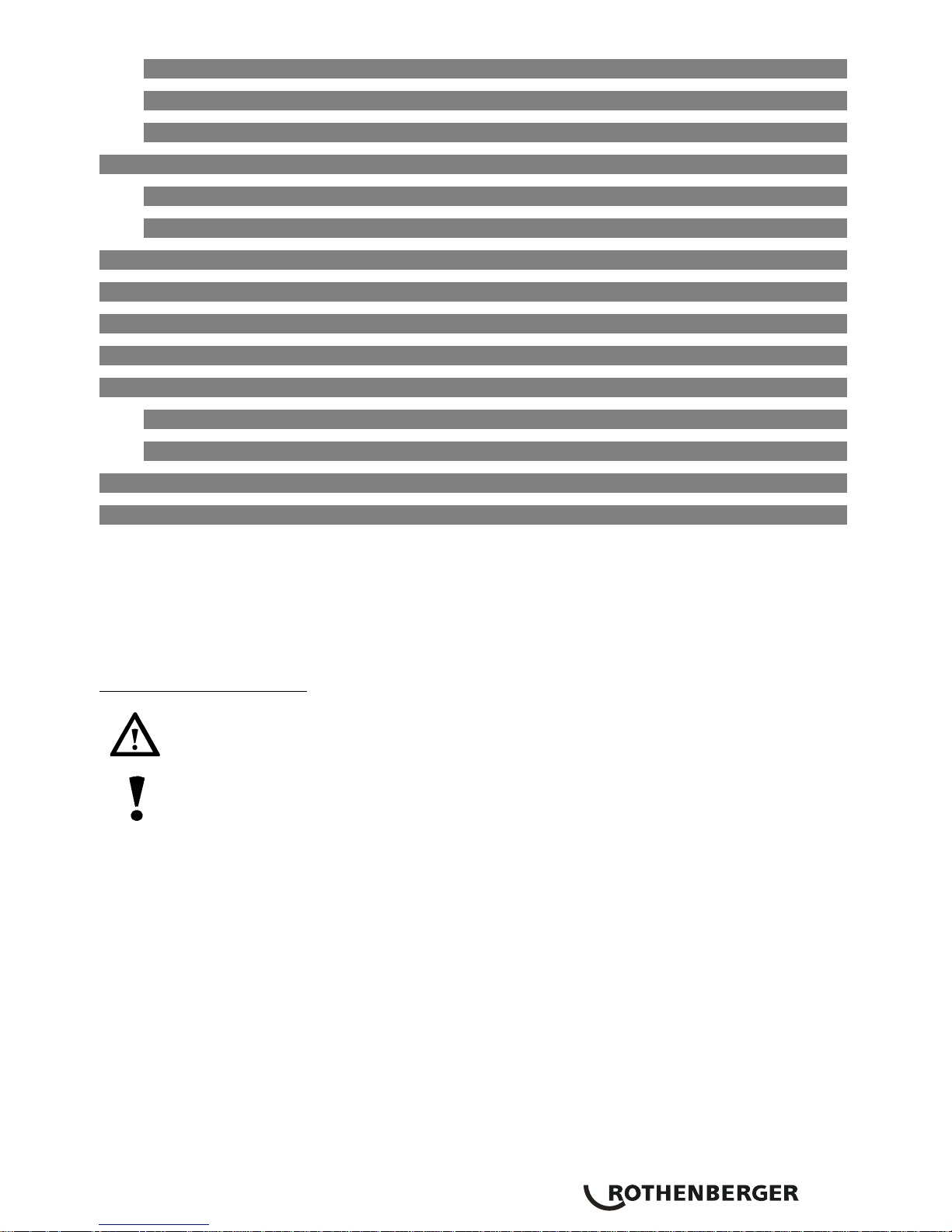
3.2 Standard Equipment
The ROSCOPE 1000 inspection device comes with the following items:
- Handheld unit
- Battery
- Battery Charger (Euro power cord only)
- USB Cable
- 1 m (3’) Imager (Connector Style A, Black Color)
- Manual, CD & SD card
- Blow Mold Case
Figure 1 – System Components
3.3 To Remove or Install the Battery Pack
Tool Assembly
To reduce the risk of serious injury during use, follow these procedures for proper
assembly.
NOTE: Battery delivered with partial charge. It is recommended that the battery be fully charged
before use. See Battery and Charger.(Section 15)
To Remove or Install the Battery Pack:
NOTE: Be sure to read Battery Precautions section.(Section 15.2)
1. With dry hands, place thumb on latch and depress. (Figure 2).
Figure 2 – Battery Cap
8 ENGLISH
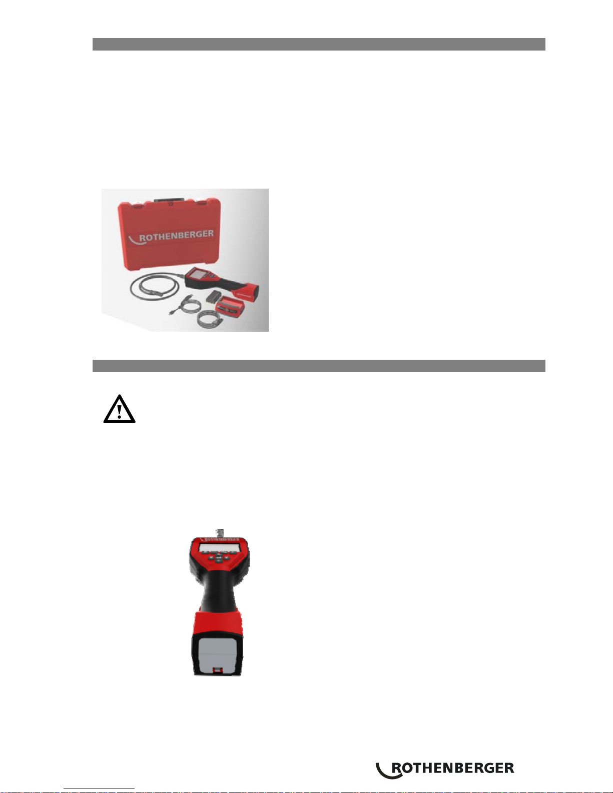
2. Lift and pull to remove cap when released.
Figure 3 – Removing/Installing Battery
3. Battery removal and installation (Figure 3)
To remove the battery pack, tilt unit slightly to slide battery into other hand. (Figure 3)
To install the battery, insert contact end of rechargeable battery pack into the ROSCOPE 1000
inspection device battery compartment. (Figure 3)
4. Replace battery cover (Figure 2) and snap into place.
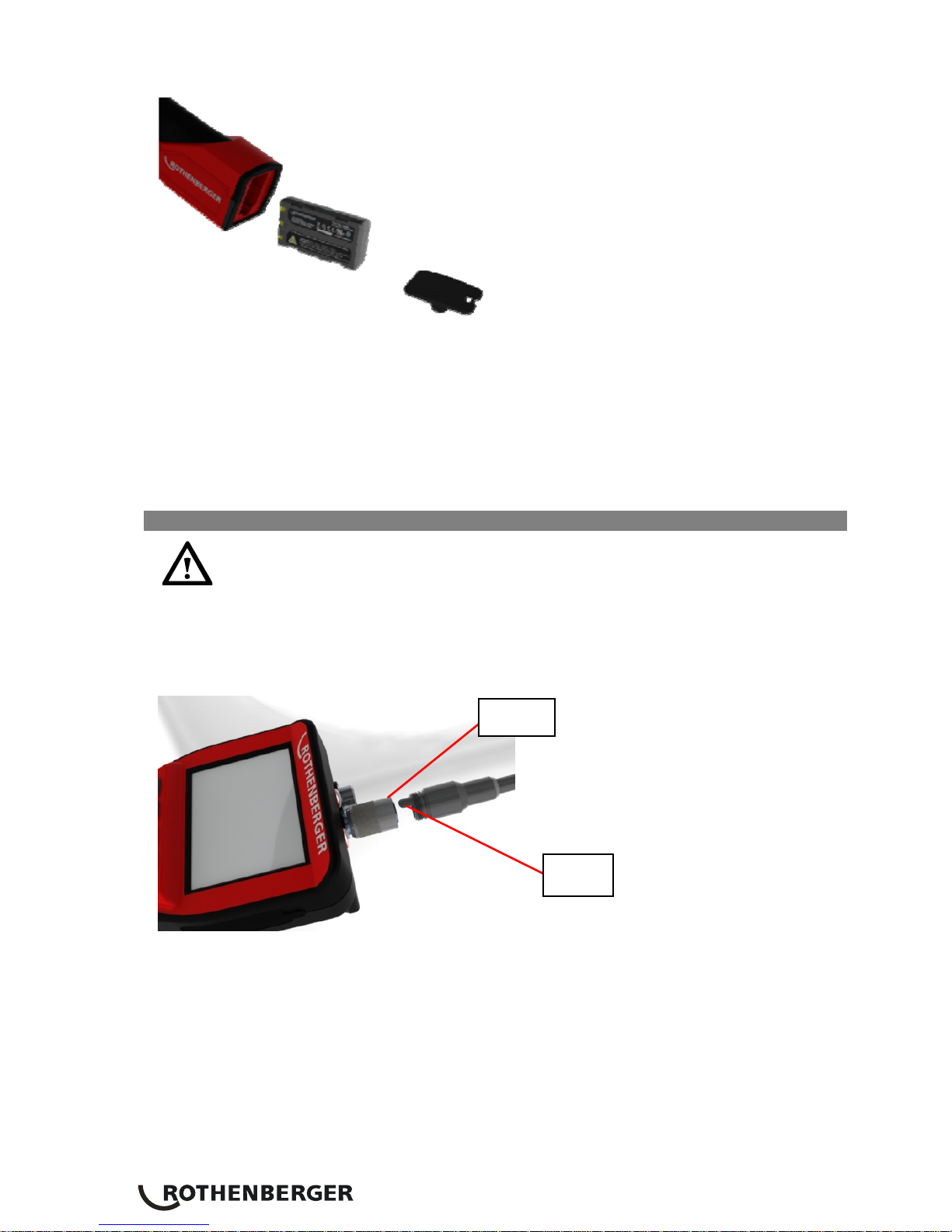
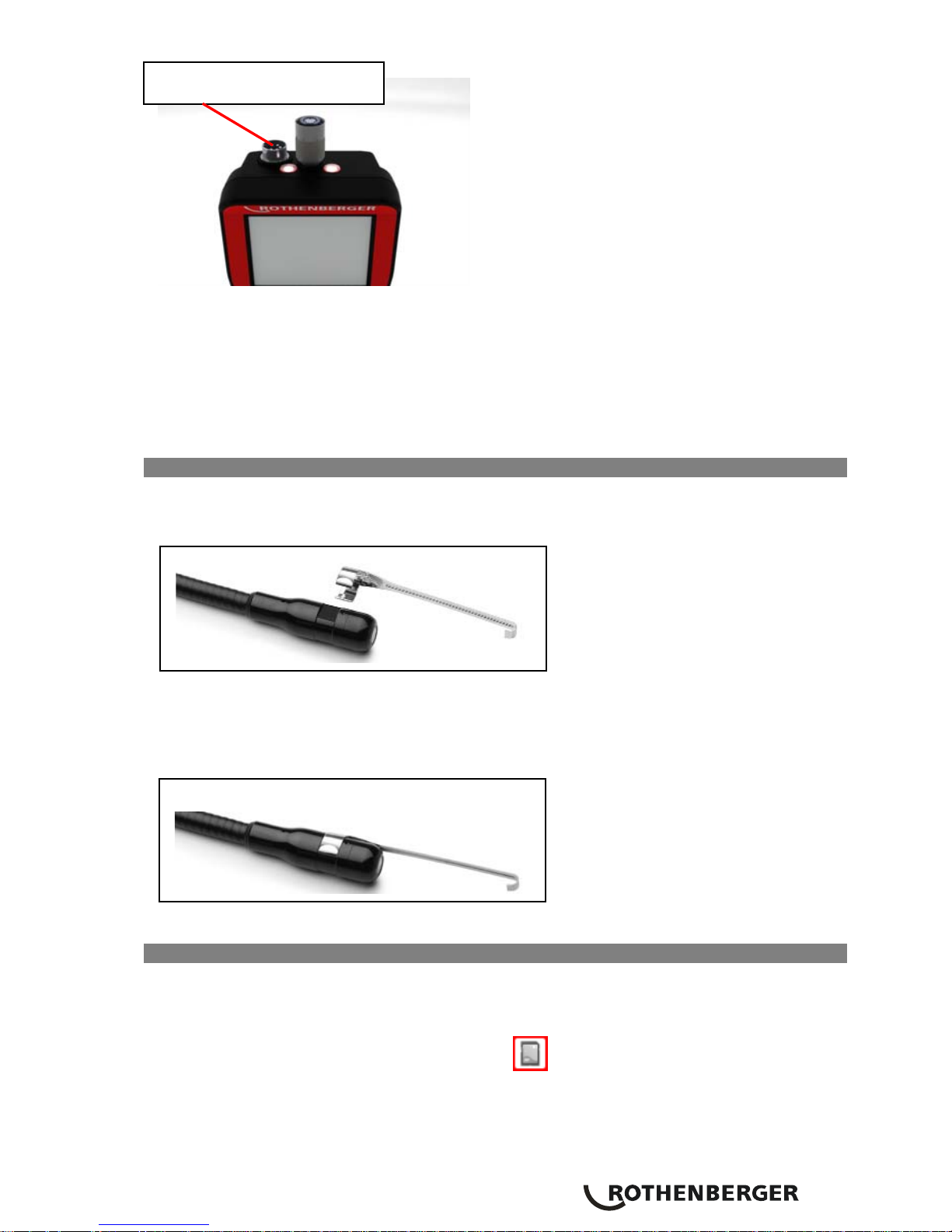
3.4 Installing the Imager Head Cable
Only one imager should be connected to the unit at a time. Always make sure the unit is
off when installing or removing an imager.
To use the ROSCOPE 1000 inspection device, the imager head cable must be connected to the
handheld device. To connect the cable to the handheld device, make sure the key and slot (Figure
4 and 5) are properly aligned. Once they are aligned, hand-tighten the knurled nut to hold the
connection in place.
Figure 4- Cable Connections (Connector Style A, Black Color)
Slot
Key
ENGLISH
9
Figure 5 – Cable Connections (Connector Style B, Silver Color)
NOTE: Connector Style B is used to attach previous versions of the RoScope Imager Cable.
1.3m (4’) cable extensions are available, for Connector A imager only, to increase the length of
your cable up to 10.7m (35’) in length. To install an extension, first remove the imager cable from
the handheld device by loosening the knurled nut. Connect the extension(s) to the handheld
device as described above (Figure 4). The keyed end of the imager head cable connects to the
slotted end of the extension.
3.5 To Install Camera Accessories
Figure 6 shows a mirror, hook and magnet (accessories sold separately). Each accessory attaches
to the (provided) Connector Style A Imager Head the same way.
..................................................................................
..................................................................................
..................................................................................
..................................................................................
..................................................................................
Figure 6 –Connector Style A accessories (sold separately)
To attach an accessory, hold the imager head as shown in Figure 7. Slip the semicircle end of the
accessory over the flats of the imager head as shown in Figure 6. Then rotate the accessory a 1/4
turn so the long arm of the accessory is extending out as shown (Figure 7).
..................................................................................
Figure 7 – Installing an Accessory on the Connector A imager
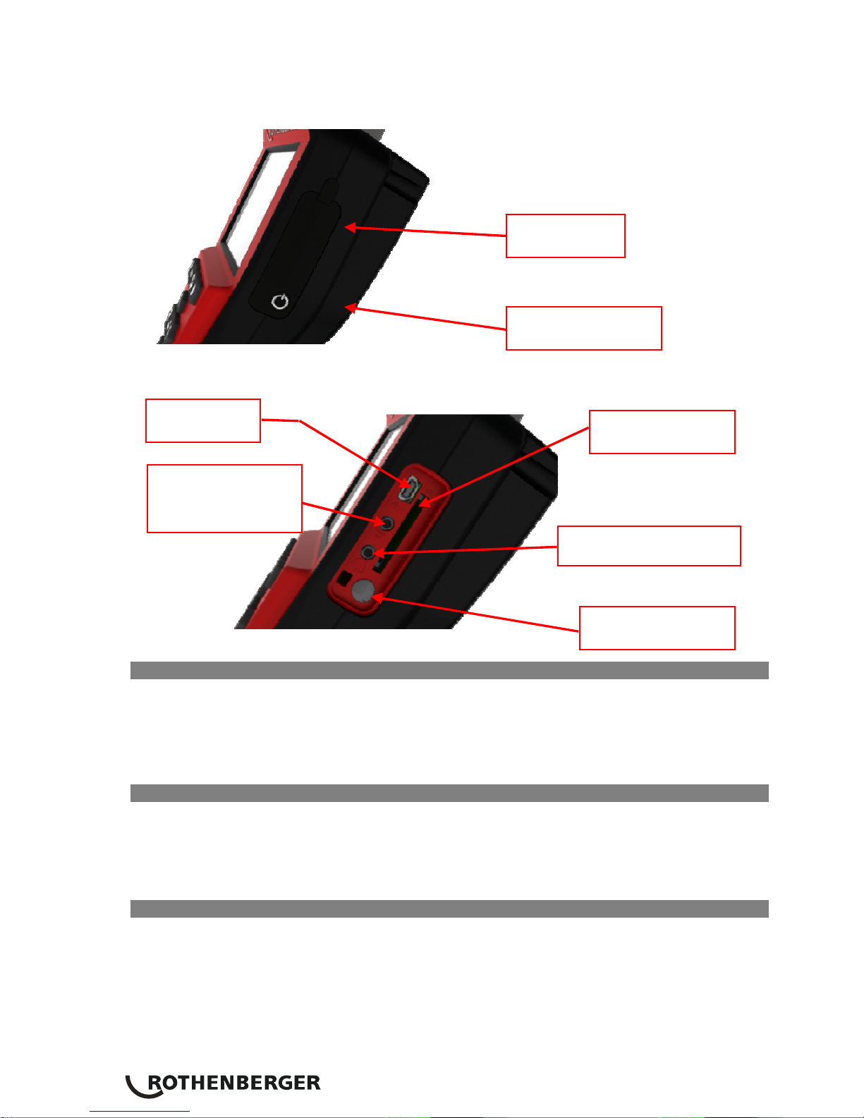
3.6 To Install an SD Card
Using the tab on the port cover (Figure 8), lift and pull to remove the cover and expose the SD
card slot. (SD card is included). Insert the SD card into the slot (Figure 9) making sure the contacts
are facing towards you and the angled portion of the card is facing down.
When an SD card is installed, a small SD card icon
will appear in the bottom right hand
portion of the screen, along with the number of images or length of video that can be stored on
the SD card.
Slot for Connector Style B
10 ENGLISH
NOTE: When the SD card is installed, the software does not use internal storage memory.
To record or review pictures and video on internal storage memory, remove the SD card.
Buttons, Controls and Ports
Figure 8 – Port Cover and Power Button
Figure 9 – Unit Inputs
3.7 Using an External Monitor (applies to Connector B imager only)
The video output port can only be used for displaying live images. Using the tab on the port cover
(Figure 8), lift and pull to remove the cover and expose the video output port (Figure 9). Connect
the ¼” mono mini-plug (sold separately) into the video output port. Connect the RCA end of the
video cable into the external monitor. Refer to your monitor’s instruction manual for displaying
video inputs.
3.8 Using the Audio Input
Using the tab on the port cover (Figure 8), lift and pull to remove the cover and expose the audio
port (Figure 9). Connect the audio headset (sold separately) to the audio port. You can now use
the headset to record audio to a video, add a voice tag (see “On Screen Navigation” Section 9.7
and 9.10 for instructions) to a saved picture, or listen to previously recorded audio.
3.9 Tool Inspection
1. Keep connectors clean
2. Inspect Battery for signs of wear or damage
3. Inspect Battery Charger for signs of wear or damage
4. Clean any foreign contaminants (grease, dirt, oil or sewage) from the device. Imager glass
must be free of any debris to ensure optimal performance.
5. Be aware of all warnings on label as shown in figure 10
Mini USB
SD Card Slot
Audio In/Out Port
Video Out Port
(Select Imagers
only)
Power Button
Power Button
Port Cover
ENGLISH
11
Figure 10 – Warning Label
3.10 Tool and Work Area Set-Up
- Check work area for proper lighting,
- Flammable liquids, vapors or dust are not present in the work area
4. Operating Instructions
- Read the entire manual
- Charge battery and install
- Battery should be removed during storage to promote battery life
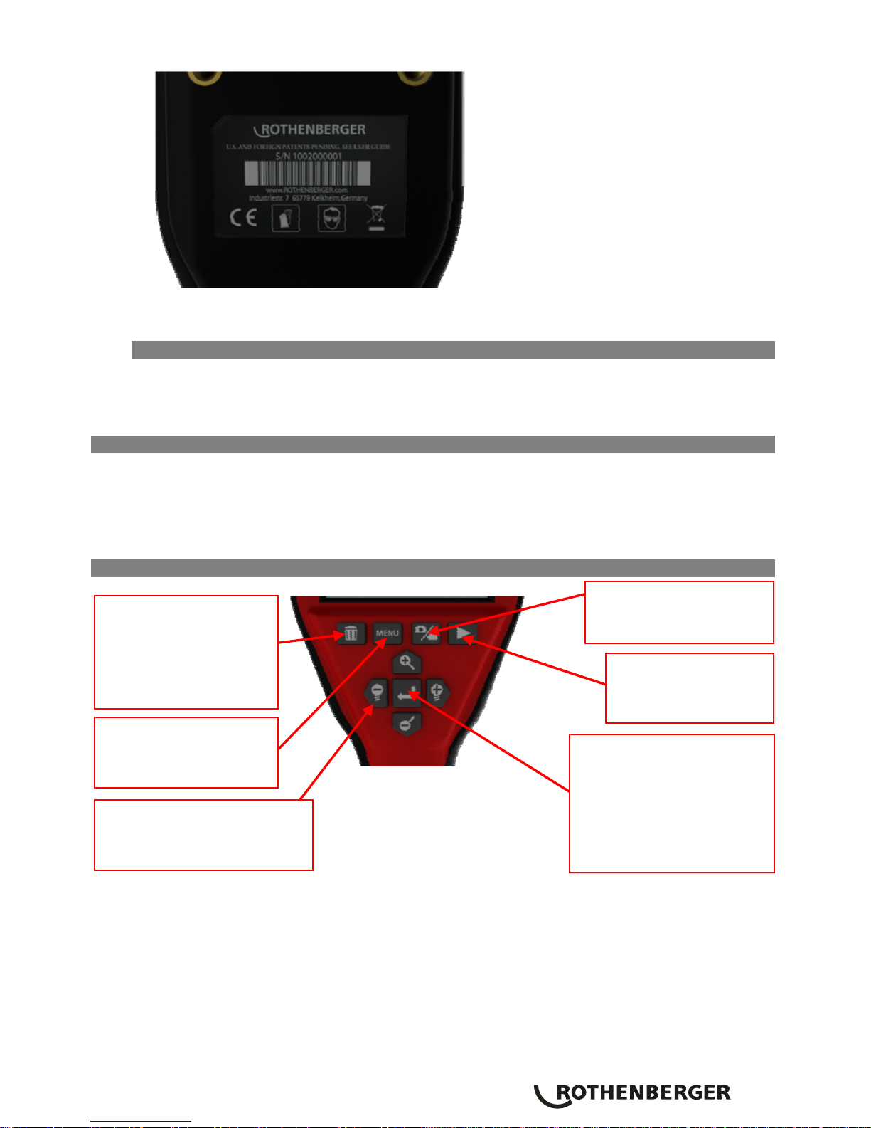
5. Controls
Figure 11 –
Figure 11. - Control Buttons
Review Mode:
Review
Video/Pictures
Delete Button: Delete
picture/video/audio tag
when in review mode.
Menu Button:
Access/Exit Menu or
previous menu item
Enter: Capture Picture (or
video),
Select Menu Item, Add
audio tag
when in saved image
review review mode.
Control Arrows:
Zoom/Brightness
Adjustment, Navigation, Pan
Change the between
Video/Picture Mode
12 ENGLISH
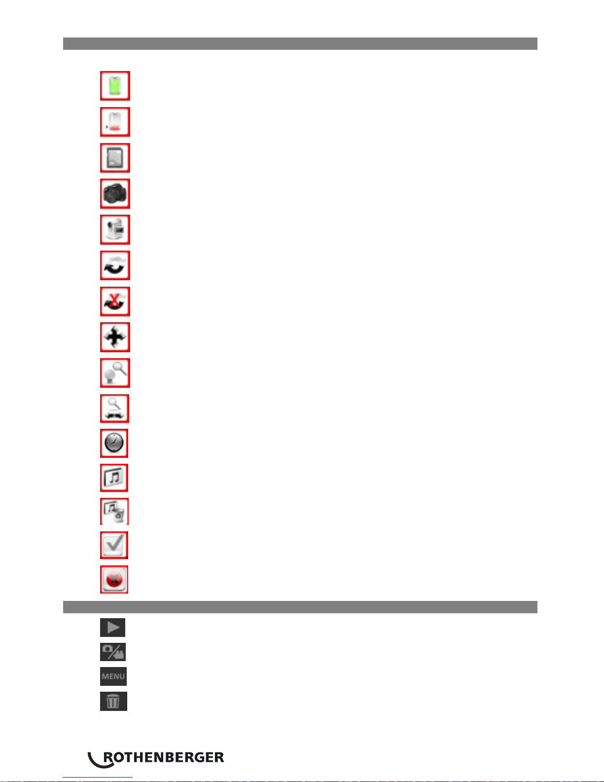
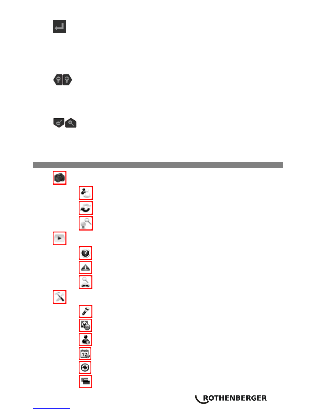
6. Icons
ON SCREEN ICONS
Battery Life Indicator – Full
Battery Life Indicator – Low
SD Card Inserted
Indicates Camera Mode
Indicates Movie Mode
Up-is-Up is ON
Up-is-Up is OFF
Pan Mode
Brightness/Zoom Mode (Live Mode)
Zoom Mode (Review Mode)
Processor Busy – Please Wait
Audio Icon
Audio Delete Icon
Confirm Icon
Cancel Icon
7. Button icons
Saved Image Review/Live Mode
Changes between Camera/Video Mode
Enters/Exits Menu
Delete Video/Image/Audio (Review Mode Only)
ENGLISH
13
General Purpose Button:
- Capture Video/Picture (Live Image Mode Only)
- Select (Menu Mode Only)
- Add/ Play Audio Tag (Reviewing a Captured Image Only)
- Play/ Pause Video (Reviewing a Captured Video Only)
General Purpose Buttons:
- LED Brightness Control (Live Image Mode Only)
- Pan LEFT/RIGHT (Live Image and Image Review Mode)
- Menu and/or Image Navigation (Menu / Image Review Mode)
General Purpose Buttons:
- Zoom Control (Live Image Mode Only)
- Pan UP/DOWN (Live Image and Image Review Mode)
- Menu and/or Image Navigation (Menu / Image Review Mode)
8. Menu icons
CAMERA SETTINGS
Black and White vs Color
UP is UP Settings
LED Brightness/Zoom or Pan Settings (For Live / Image Review Modes)
PLAYBACK SETTINGS
Display file settings
Format SD Card
Zoom or Pan settings (For Live / Image Review Modes)
TOOLS
Exterior (Handheld Device) Lights
Auto shutdown
Firmware Version
Set time and Date
Factory Reset
Language
14 ENGLISH
9. On Screen Navigation
NOTE: The following screen navigations will ONLY occur when the inspection device is
powered up.
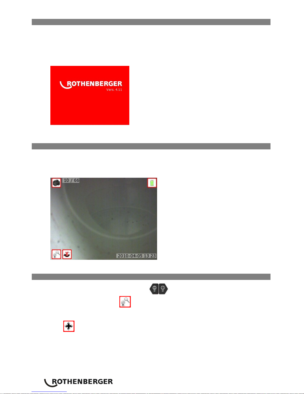
When the Roscope 1000 inspection device is powered on, the first screen that is displayed is
referred to as the splash screen (Figure 12). This screen tells you the device is booting up. Once
the product is fully powered up, the screen will automatically switch to the live screen.
Figure 12-Splash Screen
9.1 Live Screen
During the live screen mode, the device’s screen provides the user a “live” color image of what
the camera is viewing. The user has the ability to capture still-images and full-motion video, pan,
zoom, and adjust the LED brightness.
Figure 13 – Live Screen
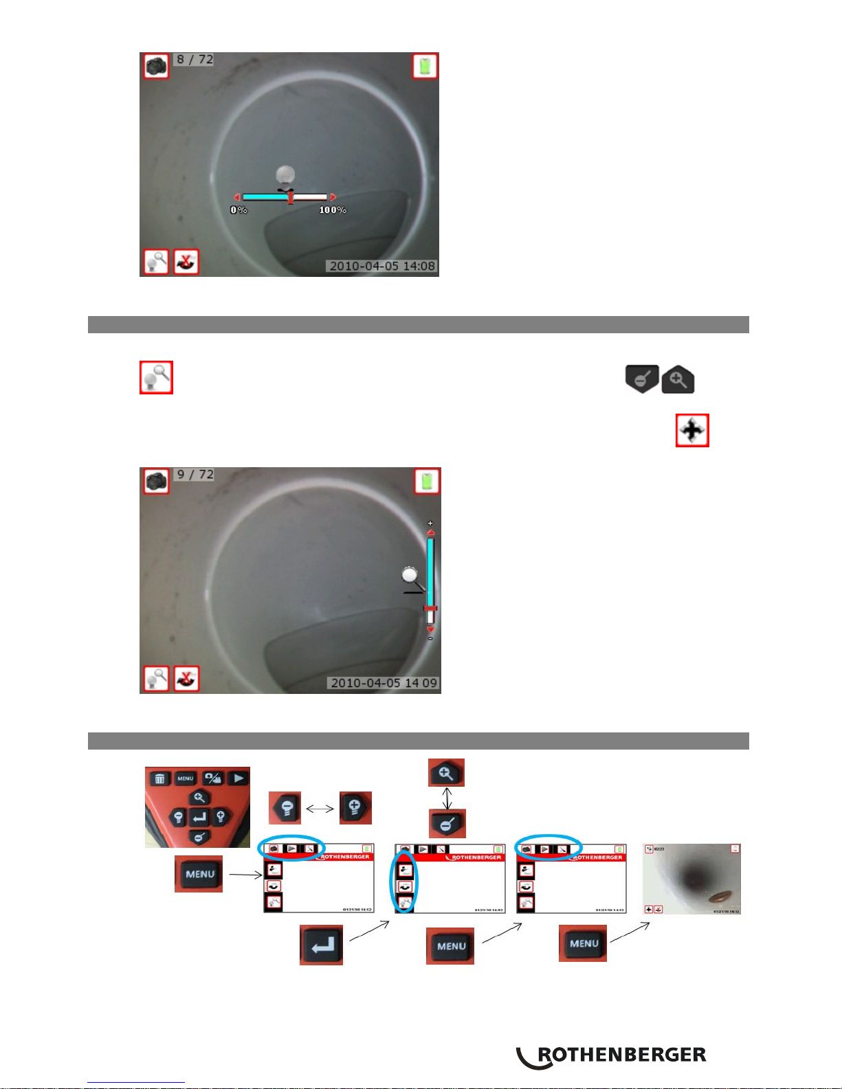
9.2 Adjust imager LED brightness
Pressing the (-) or (+) button on the key pad
will increase or decrease the LED brightness.
A brightness/zoom mode icon
will be displayed on the live screen as you adjust the
brightness (Figure 14).
Note: If the LED brightness does not change verify that the unit is not in alternate “pan”
mode
.
ENGLISH
15
Figure 14 – Adjusting the LED brightness
9.3 Zoom
The ROSCOPE 1000 inspection device has a 2x digital zoom (Figure 15). The Zoom mode icon
should appear on the live screen. Simply press the up and down arrows while in
the live screen to zoom in or out.
Note: If the Zoom does not change verify that the unit is not in alternate “pan” mode
.
Figure 15 – Adjusting the Zoom Setting
9.4 Screen Navigation
Figure 16 – Screen Navigation
16 ENGLISH
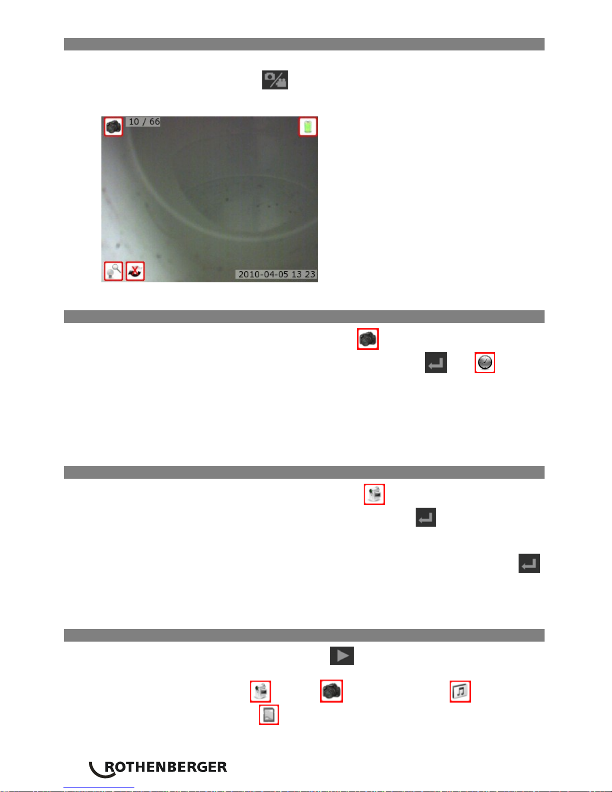
9.5 Change from Still Image Capture to Video
The ROSCOPE 1000 inspection device defaults to still image capture when powered ON.
To switch to video mode, press the
button while in live mode. The image in the upper left
corner of the screen will change to indicate the still image or video mode. (Figure 17)
Figure 17- Still Image to Video Mode
9.6 Capturing an Image
While in the live screen, make sure the still camera icon
is present at the top left portion of
the screen. To capture an image press the capture video/picture button
. The icon will
appear on the screen while the unit is saving the image or video. This indicates the still image or
video is being saved to the internal memory or SD card. You will also notice that the number at
the bottom of the right hand portion of the screen has advanced to 1/25. This means that you
have one image saved out of a total capacity of 25 (estimated). The number to the right will
change as different capacity SD cards are used or the image quality is adjusted.
Note: When using internal memory the “save” process will take longer then with an SD card.
9.7 Capturing a Video
While in the live screen, make sure the video camera icon
is present at the top left portion of
the screen. To capture a video press the capture video/picture button
. The video camera icon
will start to blink. This indicates video is saving to the internal memory or SD card. The time at the
bottom right hand portion of the screen will begin counting down.
This indicates how much video you can collect on the internal memory or SD card. Press the
button again to stop the video.
Note: When using the internal memory, videos are limited to 10 second intervals. The “save”
process (when using internal memory) can take up to a few minutes.
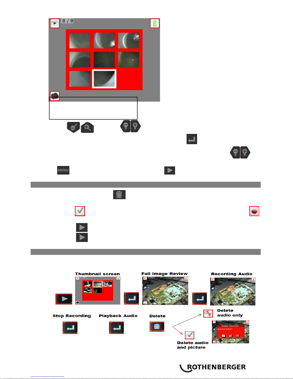
9.8 Reviewing Saved Files
Pressing the saved image review/live mode button
will take you to playback mode. The live
screen will change to thumbnail view. The icons on the bottom, left corner will indicate if the
highlighted thumbnail is a video
or picture , contains an audio tag (see section
9.10), or is using external memory
.
ENGLISH
17
Figure 18 – Thumbnail Screen-Primary Settings Screen
Use the
buttons or buttons to browse through the thumbnails.
Highlight the thumbnail you would like to review and press the
button to enter full screen
mode. While in full screen mode and with alternate function “Pan” turned off, the
buttons can be used to go to the previous or next saved file. To return to thumbnail mode press
the
button. To exit back to live mode press the button.
9.9 Deleting Saved Images
Pressing the trash can button
while viewing an image will bring you a text box asking you
if you are sure you want to delete the image. If you want to delete the image, highlight the
check mark
icon and press select. If you do not want to delete the image, highlight the
icon and press select.
Pressing the
button will take you to the thumbnail screen (Figure 18).
Pressing the
button again will take you to the live screen.
9.10 Adding and removing an audio tag to an image
To record an audio tag onto an image (Figure 19), the audio headset accessory (Rothenberger Part
#6.9616, sold separately) must be plugged into the Audio port of the handheld unit, see Figure 9.
Figure 19 – Adding and Removing an Audio Tag
Indicator Icons
#1
#4
#3
#2
#5 #6
#7
18 ENGLISH
9.11 Deleting Images and Video
Files can be deleted in thumbnail or full screen mode. Refer to “Reviewing Saved Files” – Section
9.8 to enter thumbnail or full screen mode. Select the image or video you would like to delete by
using the
buttons. Press the button to delete a file. If an audio tag is
present you may delete just the audio by selecting the
icon. Otherwise select to delete
both Audio Tag (if present) and Image or
to cancel. Once a file is deleted it cannot be
retrieved.
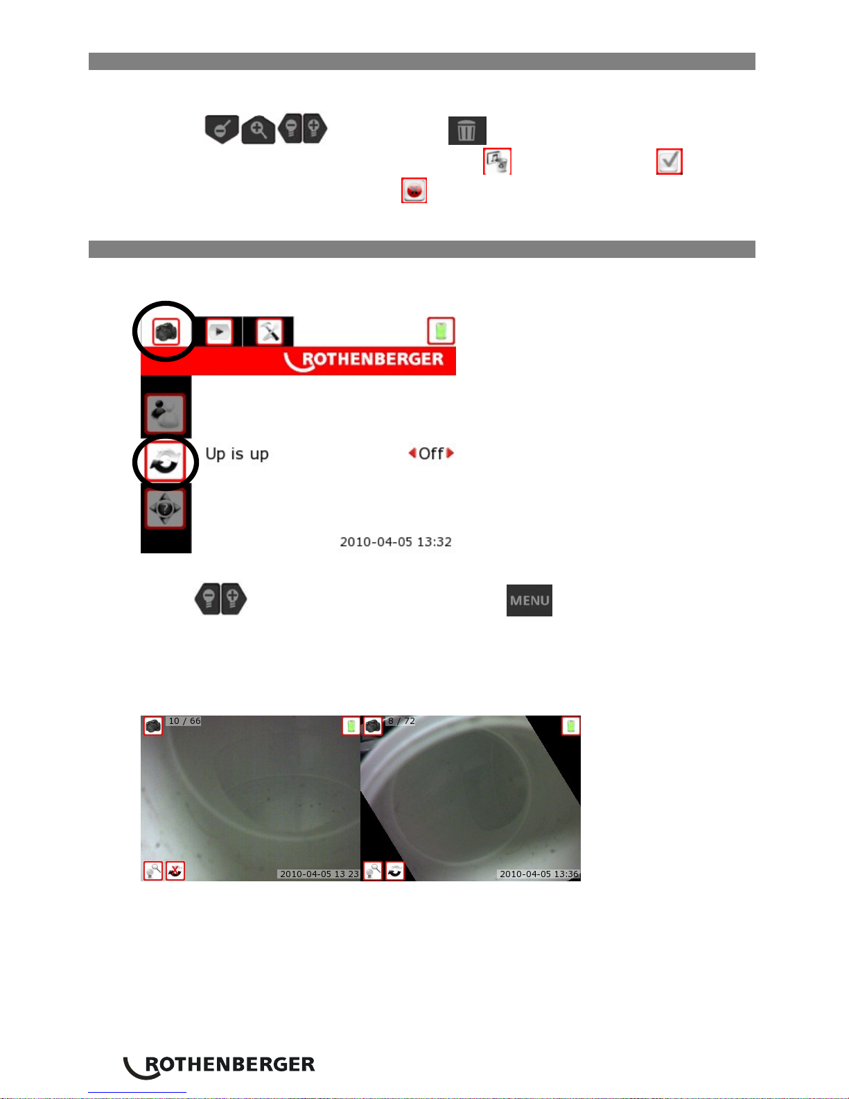
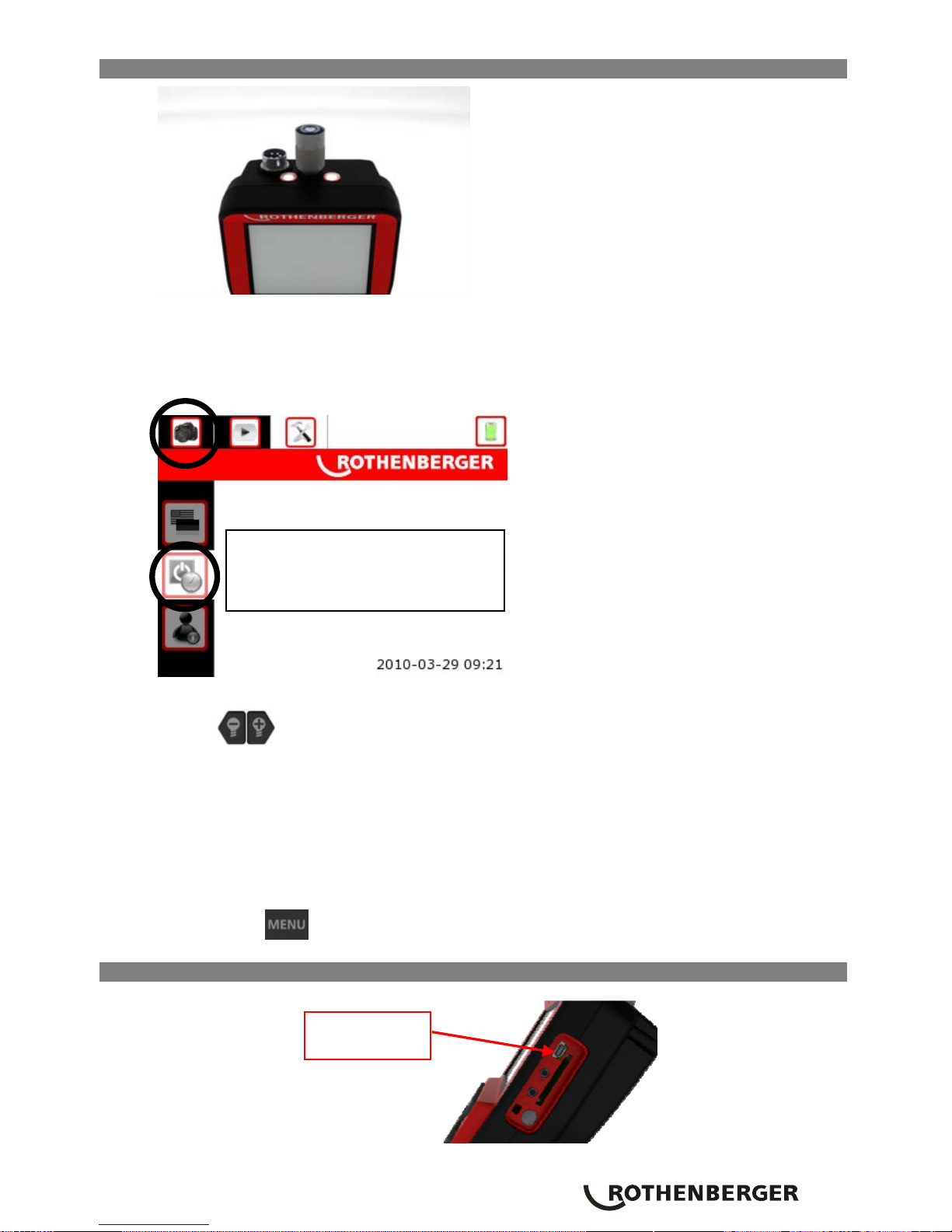
9.12 Turn Self Levelling On or Off
Refer back to section 9.4 for screen navigation architecture, the menu screen necessary to change
this feature is shown in Figure 20 below.
Figure 20 – Up-is-Up Menu Setting
Use the
buttons to change the setting. Press the button two times to exit into
live mode. You will notice that in the live image, your picture is now rotated “up” with respect to
gravity.
NOTE: You may witness black regions around the perimeter as the live image rotates within the
LCD (see Figure 21). This is a normal result of the format of the imager, zooming in on the
live image will reduce this.
Figure 21 – Up-is-Up OFF / Up-is-Up ON
ENGLISH
19
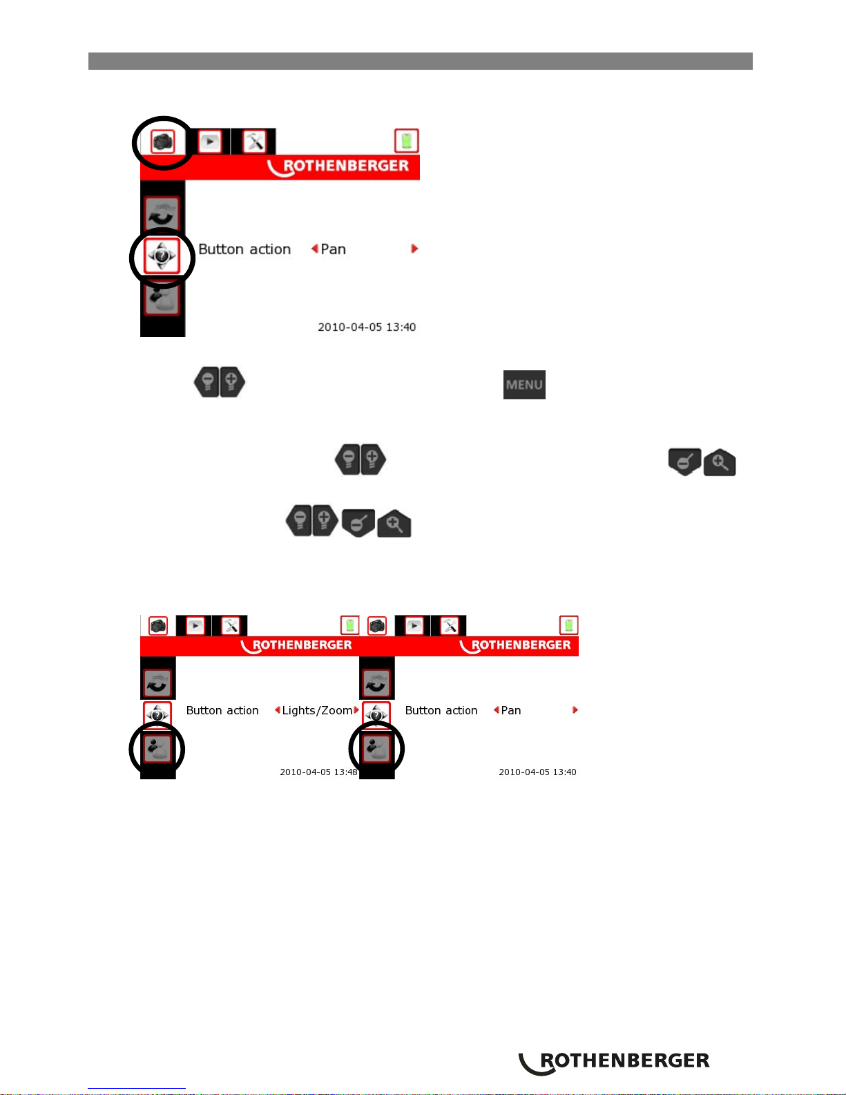
9.13 Pan/Zoom and Brightness Mode for live image
Refer back to section 9.4 for screen navigation architecture, the menu screen necessary to change
this feature is shown in Figure 22 below.
Figure 22 – Pan/Zoom [Live Image] Menu Setting
Use the
buttons to change the setting. Press the button two times to exit into live
mode. You will notice that in the live image, the icon at the bottom left of the screen will display
the mode that the device is currently set to (see Figure 23).
Î In LED / Zoom Mode the
buttons will change LED brightness and the
buttons will control the zoom level.
Î In Pan Mode the
buttons allow the user to move the picture around on
the LCD display.
NOTE: You may witness black regions around the perimeter as the live image moves within the
LCD. For maximum benefit of the Pan feature the device should be fully zoomed in.
Figure 23 – LED-Zoom Mode / Pan Mode
20 ENGLISH
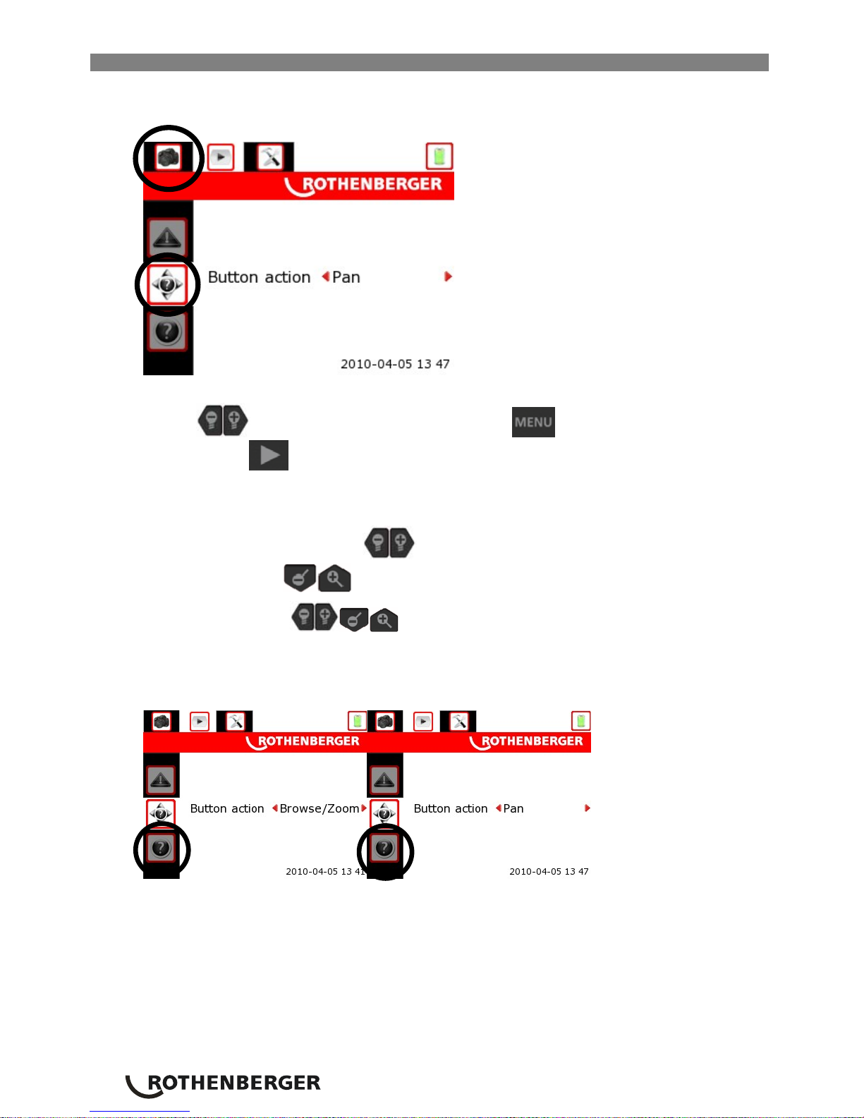
9.14 Pan/Zoom Mode for image review
Refer back to section 9.4 for screen navigation architecture, the menu screen necessary to change
this feature is shown in Figure 24 below.
Figure 24 – Pan/Zoom [Image Review] Menu Setting
Use the
buttons to change the setting. Press the button two times to exit into live
mode. Press the
button to review pictures (see Section 9.8) and select a picture of interest
to view in Full Screen Mode (see Figure 24). You will notice that in the stored image review (Full
Screen Mode), the icon at the bottom left of the screen will display the mode that the device is
currently set to (see Figure 23).
Î In Browse / Zoom Mode the
buttons will “Browse” through the full screen [stored]
images and the
buttons will control the zoom level.
Î In Pan Mode the
buttons allow the user to move the picture around on the
LCD display.
NOTE: You may witness black regions around the perimeter as the stored image moves within
the LCD. For maximum benefit of the Pan feature the device should be fully zoomed in.
Figure 25– Browse-Zoom Mode / Pan Mode
ENGLISH
21
9.15 Turning on the Exterior (Handheld Device) Lights
Figure 26– Location of the Exterior Lights
Refer back to section for menu navigation architecture Section 9.4, the menu screen necessary to
change this feature is shown in Figure 27 below.
Figure 27 – Exterior (Handheld Device) Light Settings
Use the
buttons to change the setting.
1. Auto Mode – The External (Handheld Device) Lights turn on with the Imager LEDs (see
section 9.2 for turning the Imager LEDs on)
NOTE: the intensity of the External Lights does not change; they are either ON or OFF.
2. On Mode – The External (Handheld Device) Lights are always in the ON position regardless
whether the Imager LEDs are in use. When the unit is on, the External Lights are on.
3. Off Mode – The External (Handheld Device) Lights are always in the OFF position regardless
whether the Imager LEDs are in use.
Press the
button two times to exit into live mode.
10. Transferring Images to a computer
Figure 28 – USB Connection for Transfer
FPO
Replace with proper screen shot.
Mini USB
22 ENGLISH
10.1 Using the Camera and Scanner Wizard to Transfer Images to a Computer
1. Use the USB cable to connect the Rothenberger handheld device to the computer as
shown in Figure 28.
2. Plug the USB cable into the ROSCOPE 1000 inspection device (Figure 9), and the computer.
3. Power the device ON, a splash screen saying “USB Connected” will appear on the LCD
screen.
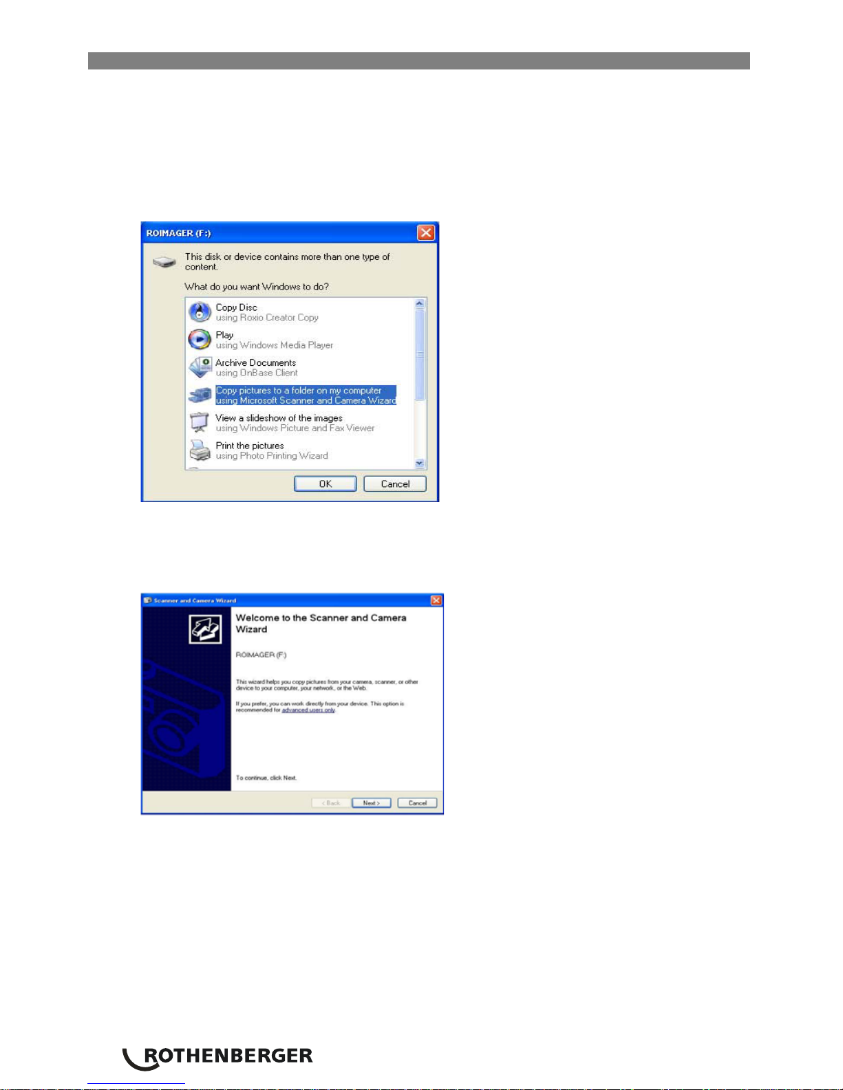
4. When the following screen is displayed on the computer. Select “Copy pictures to a folder
on my computer.”
Figure 29– Copy Pictures Window
NOTE: This will only happen provided you have pictures saved on the handheld device (or SD
card).
Figure 30– Scanner and Camera Wizard
5. When the prompt in Figure 30 appears, click “next”.
ENGLISH
23
Figure 31 – Image Select Screen
6. When the prompt in Figure 31 appears, place a check mark in the box to the upper right
hand side of the image(s) you want to save and press “next.”
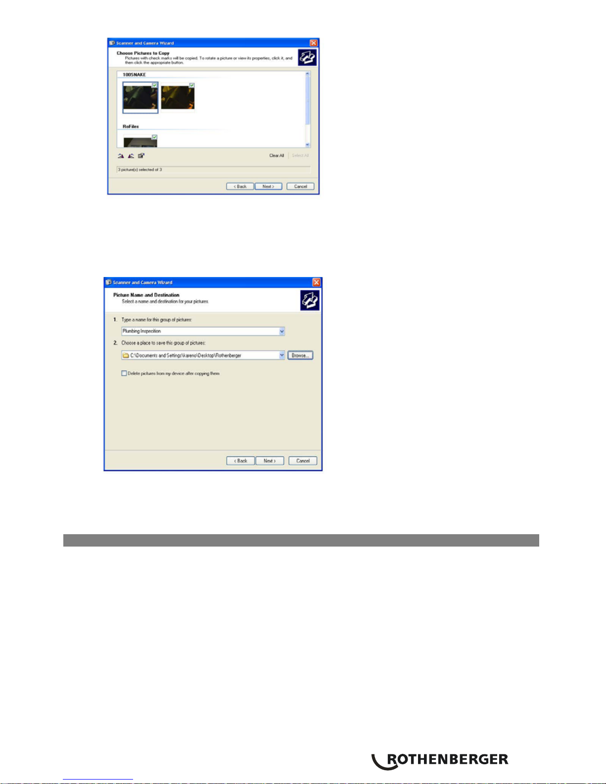
7. Fill in the name for this group of pictures and choose a location to save the files (Figure 32).
To select an alternate saving location, click browse and select a drive and folder. Press next.
Figure 32- Save Location Window
8. The pictures and the videos will save to the chosen location.
9. Follow the remaining on screen prompts to complete the task.
10.2 Manually Saving Images to Your Computer’s Hard Drive
1. Use the USB cable to connect the Rothenberger handheld device to the computer as shown
in Figure 28.
2. Plug the USB cable into the ROSCOPE 1000 inspection device (Figure 9), and the computer.
3. Power the device ON, a splash screen saying “USB Connected” will appear on the LCD
screen.
4. Click on the “My Computer” icon on your desktop.
24 ENGLISH
Figure 33 – My Computer Icon
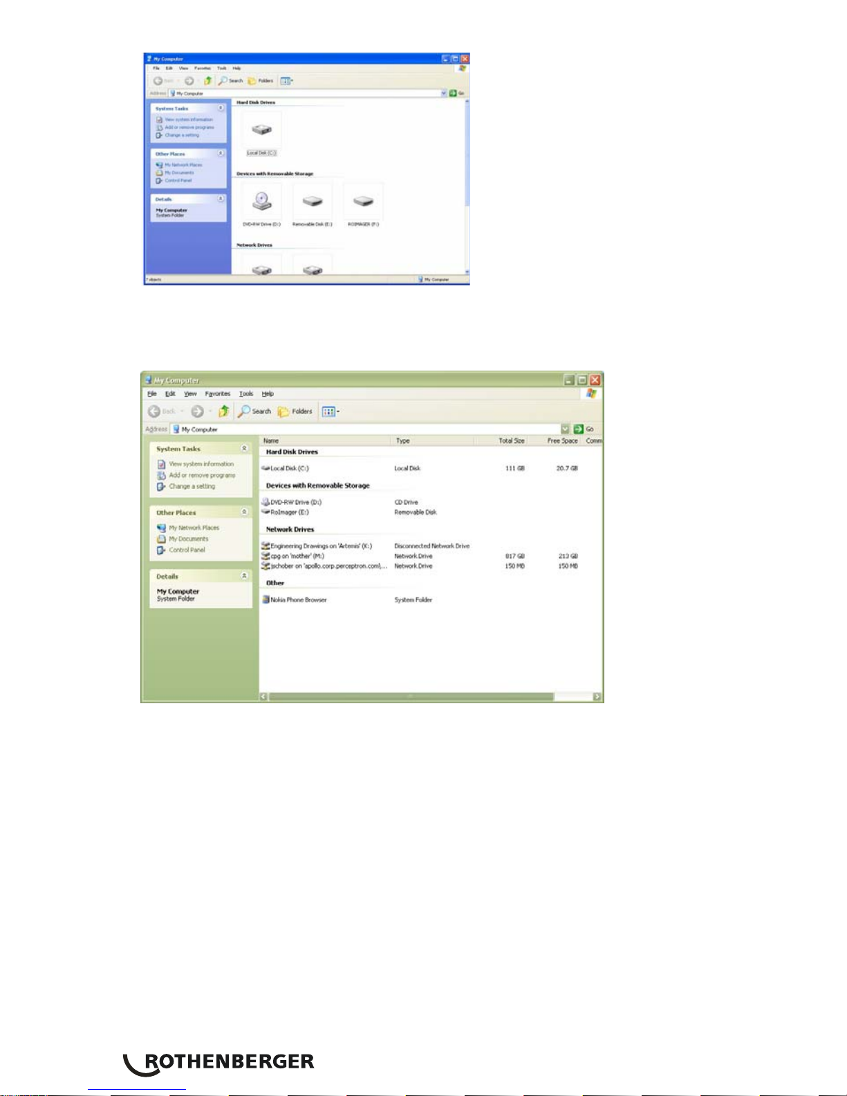
5. Select the “RoImager” from the available drives (Figure 34).
Figure 34- List of Available Drives
NOTE: Care should be taken when reviewing images and videos with this method. Files can be
permanently deleted from this screen (files are not recoverable once deleted).
This inspection device is equipped with internal memory as well as the ability to use an SD card.
When the SD card is inserted in the device, the internal memory will not be accessible until the SD
card is removed (Figure 9).

ENGLISH
25
6. Open the “DCIM” folder (Figure 35).
Figure 35 – DCIM Folder
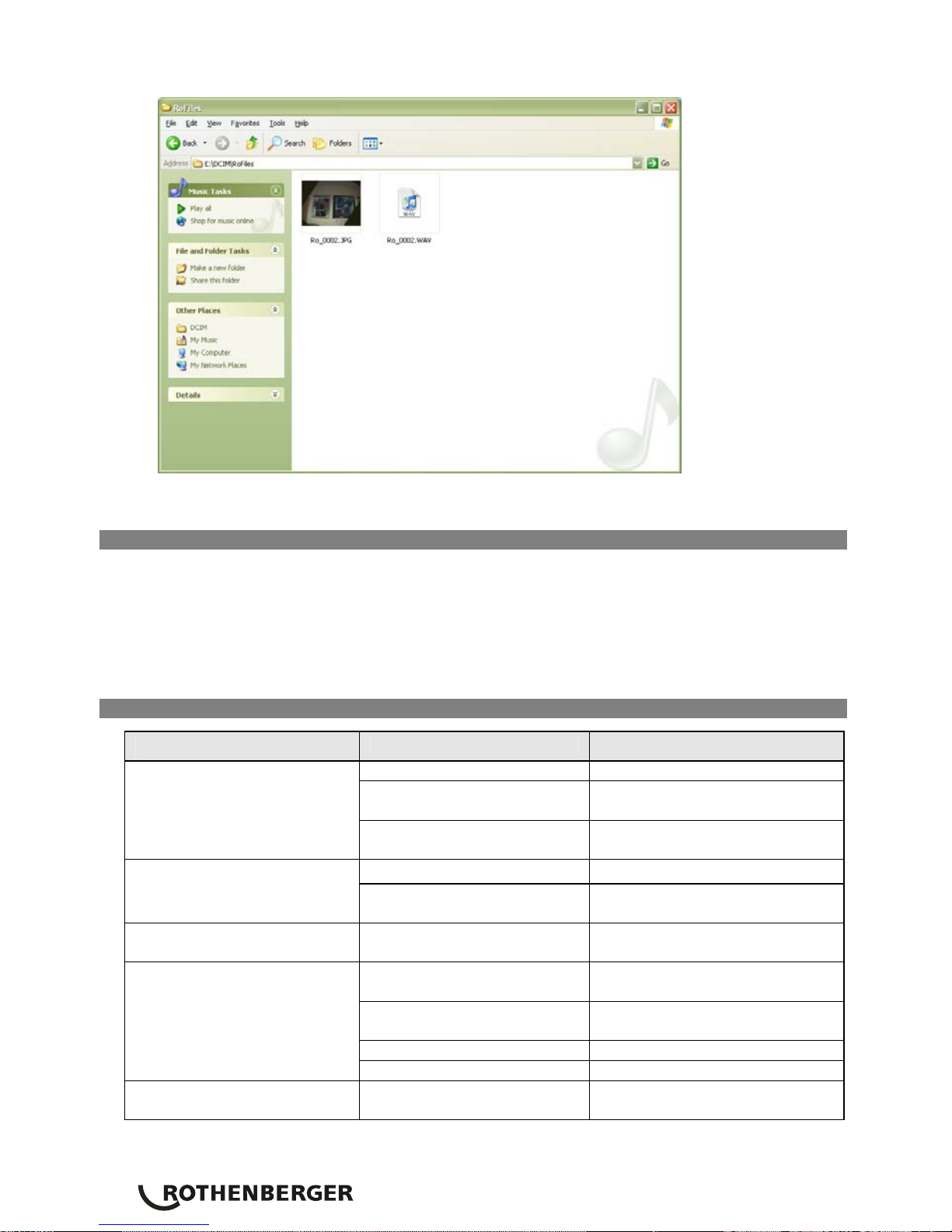
7. Open the “RoFiles” folder (Figure 36).
Figure 36 – RoFiles and RoLDR Folders (within the DCIM Folder)
26 ENGLISH
8. Copy and Paste the images into a folder of your choice on your computer’s hard drive.
Figure 37 – Image Window
11. Cleaning instruction
1. Remove battery from unit
2. Alcohol wipes, mild detergent and water to remove dirt and grease from the product.
3. Recommend soft optical cloth for cleaning the LCD window.
4. Recommend cotton cloth for cleaning imager head
5. Allow appropriate drying time before re-inserting the battery and operating.
12. Troubleshooting
Symptom Possible Reason Solution
Battery is discharged Recharge battery
Verify battery is in the
battery compartment
Place battery in the battery
compartment
Display unit does not turn on
Faulty electronics
Contact Rothenberger Service
Center
Loose cable connection Check cable connections.
Display turns on, but does
not show image.
Imager head covered by
debris
Clean imager head
Display shows an
unresponsive image
Image processor
encountered an error
Turn OFF unit/turn ON to reset
processor
Battery may have discharged
slightly during storage
Remove battery when storing
Run time dependent on LED
usage
Recharge battery more often
when extensive use of LEDs
Battery may be damaged Replace battery
Battery does not hold a
charge
Life cycles of battery expired Replace battery
Video cuts off after 10
seconds
Factory setting for internal
memory
Use SD card for videos longer
than 10 seconds.
ENGLISH
27
13. Accessories
Accessory Name Rothenberger Part Number
Replacement Standard Imager 6.9601
Hook Magnet and Mirror 6.9615
Replacement Battery 6.9618
Replacement Battery Charger 6.9619
Headset 6.9616
¼“ mono mini plug cable external monitor 6.9617
14. Storage
1. Unit should be cleaned prior to long term storage
2. Store in a cool dry location
3. Battery should be removed during storage to promote battery life.
15. Battery and Charger
1. Only use provided battery and charger
2. Operating temperature. Do not use charger below 0°C (32°F) and above 40°C (104°F)
3. Inspect Battery and Charger before usage, do not use if there is any physical damage.
Contact the Rothenberger Service Center.
4. Do not insert battery into charger if charger has been dropped or damaged in any way.
5. Proper ventilation required
6. Use an appropriate power source.
7. Recommended to unplug charger when not in use or when being cleaned.
8. The battery and charger are not serviceable parts, contact your local Rothenberger Service
Center for repairs.
9. Do not charge battery pack in damp, wet or explosive environment.
10. Properly dispose of the battery
11. Avoid contact with fluids seeping from a defective battery.
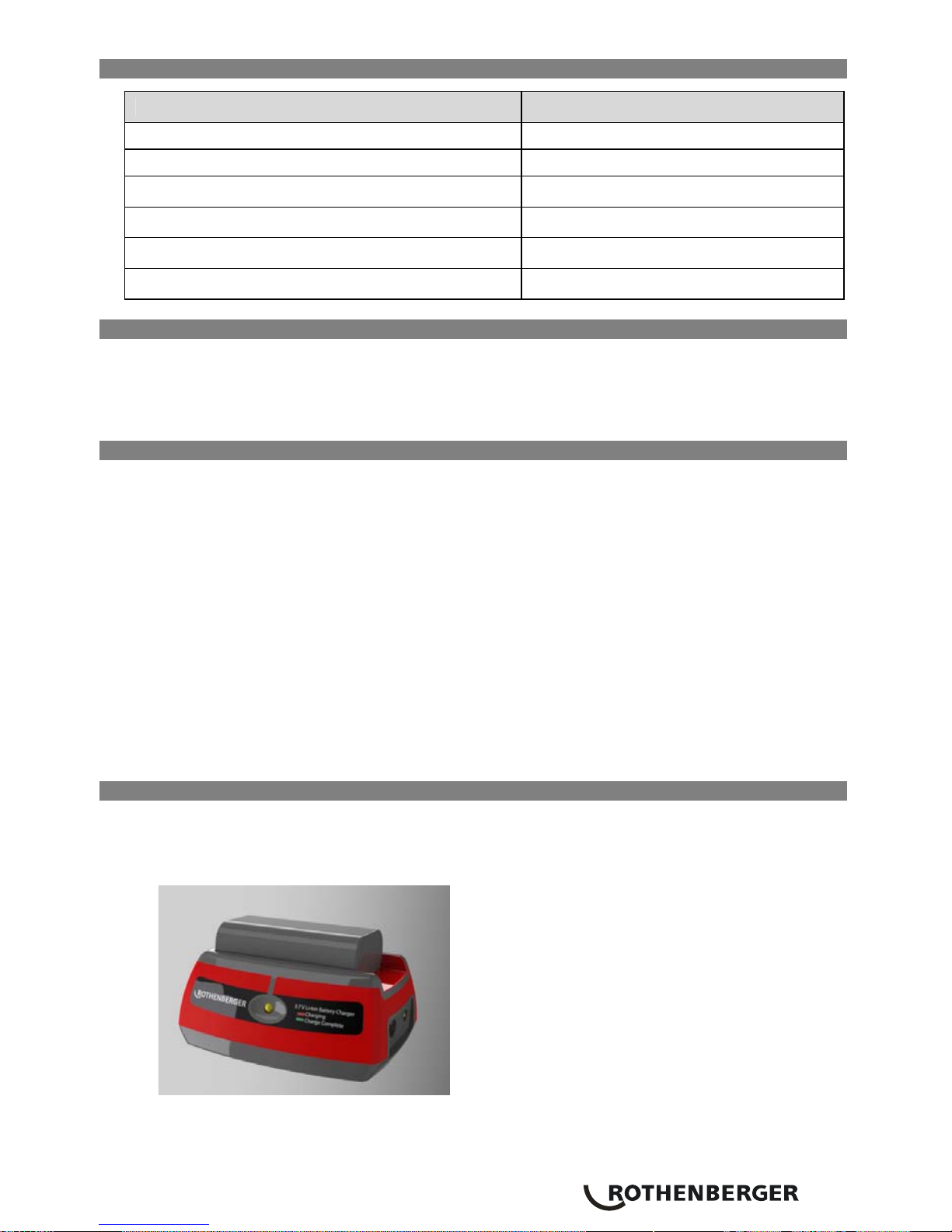
15.1 Description, Specifications and Standard Equipment
The ROSCOPE 1000 Battery Charger (Catalog Number 6.9619), when used with appropriate
battery packs (Catalog Number 6.9618) listed in the Accessories section, is designed to charge a
3.7V Lithium Ion battery in approximately 4-5 hours.
Figure 38– Battery and Charger
 Loading...