

Page 1
Owner’s manual
Manuel de l’utilisateur
Manual de Instrucciones
RSP-1098
Surround Sound Processor
Processeur de Son Surround
Procesador De Sonido Envolvente
STANDBY ZONE 2
FUNCTION VOLUME
PUSH
PATH SPEAKER
MODE DISPLAY MENU MUTE
SURROUND SOUND PROCESSOR RSP-1098
Page 2
RSP-1098
2
Page 3

3
Notice
The COMPUTER I/O connection should be handled by authorized person
only.
FCC Information
This equipment has been tested and found to comply with the limits for a
Class B digital device, pursuant to Part 15 of the FCC Rules. These limits
are designed to provide reasonable protection against harmful interference
in a residential installation. This equipment generates, uses and can radiate radio frequency energy and, if not installed and used in accordance
with the instruction, may cause harmful interference to radio communications.
However, there is no guarantee that interference will not occur in a particular installation. If this equipment does cause harmful interference to radio
or television reception, which can be determined by turning the equipment
off and on, the user is encouraged to try to correct the interference by one
or more of the following measures:
• Reorient or relocate the receiving antenna.(TV, radio, etc.)
• Increase the separation between the equipment and receiver
• Connect the equipment to an outlet on circuit different from that to which
the receiver is connected.
• Consult the dealer or an experienced radio/TV technician for additional
help.
Caution
This device complies with part 15 of the FCC Rules operation is subject to
the following to conditions: (1) This device may not cause harmful interference, and (2) this device must accept any interference received, including
interference that may cause undesired operation.
Important Safety Instructions
WARNING: There are no user serviceable parts inside. Refer
all servicing to qualified service personnel.
WARNING: To reduce the risk of fire or electric shock, do not
expose the unit to moisture or water. Do not allow foreign
objects to get into the enclosure. If the unit is exposed to moisture,
or a foreign object gets into the enclosure, immediately disconnect the power cord from the wall. Take the unit to a qualified
service person for inspection and necessary repairs.
Read all the instructions before connecting or operating the component.
Keep this manual so you can refer to these safety instructions.
Heed all warnings and safety information in these instructions and on the
product itself. Follow all operating instructions.
Clean the enclosure only with a dry cloth or a vacuum cleaner.
You must allow 10 cm or 4 inches of unobstructed clearance around the
unit. Do not place the unit on a bed, sofa, rug, or similar surface that could
block the ventilation openings. If the unit is placed in a bookcase or cabinet, there must be ventilation of the cabinet to allow proper cooling.
Keep the component away from radiators, heat registers, stoves, or any
other appliance that produces heat.
The unit must be connected to a power supply only of the type and voltage
specified on the rear panel. (USA: 115 V/60Hz, EC: 230V/50Hz)
Connect the component to the power outlet only with the supplied power
supply cable or an exact equivalent. Do not modify the supplied cable. Do
not defeat grounding and/or polarization provisions. The cable should be
connected to a 2-pin polarized wall outlet, matching the wide blade of the
plug to the wide slot of the receptacle. Do not use extension cords.
Do not route the power cord where it will be crushed, pinched, bent, exposed to heat, or damaged in any way. Pay particular attention to the power
cord at the plug and where it exits the back of the unit.
The power cord should be unplugged from the wall outlet during a lightning storm or if the unit is to be left unused for a long period of time.
Immediately stop using the component and have it inspected and/or serviced by a qualified service agency if:
• The power supply cord or plug has been damaged.
• Objects have fallen or liquid has been spilled into the unit.
• The unit has been exposed to rain.
• The unit shows signs of improper operation
• The unit has been dropped or damaged in any way
Page 4
RSP-1098
Information FCC
Cet appareil a été testé afin de vérifier sa conformité avec les normes minima
des appareils numériques de classe B, suivant l’article 15 des normes FCC.
Ces normes garantissent une protection suffisante contre les interférences,
dans le cadre d’une utilisation domestique. Cet appareil génère, utilise et
peut rayonner des fréquences radio et peut, s’il n’est pas utilisé selon les
conseils prodigués dans ce manuel d’utilisation, causer des interférences
avec les communications radio.
Il n’y a cependant aucune garantie que ces interférences n’interviennent
dans certaines installations. Si vous notez la présence de parasites sur la
radio ou la télévision (détectées par la mise sous et hors tension de l’appareil),
vous pouvez essayer d’éliminer ces interférences en essayant une des
procédures suivantes:
• Réorientez ou déplacez l’antenne de réception (TV, radio, etc.)
• Augmentez l’éloignement physique entre le récepteur en cause et l’appareil.
• Branchez les autres maillons sur une prise secteur différente de celle
sur laquelle est branché le récepteur.
• Consultez votre revendeur, ou un technicien spécialiste de ces questions
de réception radio/TV.
Attention: Cet appareil répond aux normes de l’article 15 de la FCC sous
les conditions suivantes: 1) Cet appareil ne doit pas causer d’interférence
très sensible. 2) Cet appareil doit pouvoir accepter n’importe quelle interférence
externe, y compris celles dues à une utilisation fortuite.
4
Conseils de Sécurité
ATTENTION: Il n’y a à l’intérieur aucune pièce susceptible d’être
modifiée par l’utilisateur. Adressez-vous impérativement à une
personne qualifiée.
ATTENTION: Prenez garde à ce qu’aucun objet ou liquide ne
tombe à l’intérieur de l’appareil par ses orifices de ventilation; Si l’appareil est exposé à l’humidité ou si un objet tombe
à l’intérieur, couper immédiatement l’alimentation secteur de
tous les appareils. Débrancher l’appareil des autres maillons,
et adressez-vous immédiatement et uniquement à une personne
qualifiée et agréée.
Tous les conseils de sécurité et d’installation doivent être lus avant de faire
fonctionner l’appareil. Conservez soigneusement ce livret pour le consulter
à nouveau pour de futures références.
Tous les conseils de sécurité doivent être soigneusement respectés. Suivez
les instructions. Respectez les procédures d’installation et de fonctionnement
indiquées dans ce manuel.
L’appareil doit être nettoyé uniquement avec un chiffon sec ou un aspirateur.
L’appareil doit être placé de telle manière que sa propre ventilation puisse
fonctionner, c’est-à-dire avec un espace libre d’une dizaine de centimètres
autour de lui. Il ne doit pas être posé sur un fauteuil, un canapé, une couverture
ou toute autre surface susceptible de boucher ses ouïes d’aération; ou placé
dans un meuble empêchant la bonne circulation d’air autour des orifices
d’aération.
Cet appareil doit être placé loin de toute source de chaleur, tels que radiateurs,
chaudières, bouches de chaleur ou d’autres appareils (y compris amplificateurs
de puissance) produisant de la chaleur.
Cet appareil doit être branché sur une prise d’alimentation secteur, d’une
tension et d’un type conformes à ceux qui sont indiqués sur la face arrière
de l’appareil (Europe, 230 V/50 Hz).
Brancher l’appareil uniquement grâce au cordon secteur fourni, ou à un
modèle équivalent. Ne pas tenter de modifier ou changer la prise. Notamment,
ne pas tenter de supprimer la prise de terre si celle-ci est présente. Ne pas
utiliser de cordon rallonge.
Prendre garde à ce que ce cordon d’alimentation ne soit pas pincé, écrasé
ou détérioré sur tout son trajet, à ce qu’il ne soit pas mis en contact avec
une source de chaleur. Vérifier soigneusement la bonne qualité des contacts, à l’arrière de l’appareil comme dans la prise murale.
Si l’appareil ne doit pas être utilisé pendant une longue période, la prise
secteur sera débranchée.
L’appareil doit être immédiatement éteint, débranché puis retourné au service après-vente agréé dans les cas suivants:
• Un objet est tombé, ou du liquide a coulé à l’intérieur de l’appareil.
• L’appareil a été exposé à la pluie.
• L’appareil ne fonctionne pas normalement, ou ses performances sont
anormalement limitées.
• L’appareil est tombé, ou le coffret est endommagé.
Notice
Le branchement repéré COMPUTER I/O ne concerne que des
techniciens agréés uniquement.
Page 5
5
Información de la FCC
Este aparato ha sido debidamente probado y satisface los límites de
funcionamiento correspondientes a un componente digital de Clase B
especificados en el Apartado 15 de la Normativa de la FCC. Dichos límites
han sido diseñados para proporcionar una protección razonable frente a
interferencias en instalaciones domésticas. Este equipo genera y puede radiar
energía de radiofrecuencia y en el caso de que no sea instalado y utilizado
siguiendo las instrucciones suministradas por el fabricante, puede causar
interferencias en comunicaciones de radio o televisión.
No obstante, no se garantiza que las citadas interferencias no puedan tener
lugar en una instalación particular. Si este aparato interfiere la recepción
de programas de radio o televisión, lo que puede determinarse activándolo
y desactivándolo, intente corregir la interferencia aplicando una o varias
de las siguientes medidas.
• Reoriente o reubique la antena de recepción.
• Aumente la separación entre el aparato y el sintonizador del televisor.
• Conecte el aparato a un enchufe perteneciente a un circuito eléctrico
diferente.
• En caso de que tenga cualquier otra duda, consulte a su distribuidor
autorizado de productos Rotel o a un técnico experimentado televisión
o radio.
Precaución: Este aparato cumple con el Apartado 15 de la Normativa
de la FCC y su funcionamiento está sujeto a las siguientes condiciones: (1)
Este aparato no debe provocar interferencias perjudiciales, y (2) debe aceptar
cualquier interferencia que reciba, incluyendo aquellas que puedan afectar
negativamente a su funcionamiento.
Nota Importante
La conexión COMPUTER I/O debería ser manipulada únicamente por
personal autorizado.
Instrucciones Importantes Relacionadas
con la Seguridad
ADVERTENCIA: No hay componentes manipulables por el
usuario en el interior del aparato. Cualquier operación de
mantenimiento debe ser llevada a cabo por personal cualificado.
ADVERTENCIA: Para reducir el riesgo de que se produzca un
incendio o una descarga eléctrica, no exponga el RSP-1098 al
agua o la humedad. No permita que ningún objeto extraño penetre
en el interior del aparato. Si el aparato está expuesto a la humedad
o algún objeto extraño penetra en su interior, desconecte
inmediatamente el cable de alimentación de la red eléctrica. En
caso de que fuera necesario, envíe el aparato a un especialista
cualificado para su inspección y posterior reparación.
Lea todas las instrucciones del presente manual antes de conectar o hacer
funcionar el RSP-1098. Conserve este manual cerca de usted para el caso
de que necesite revisar las instrucciones de seguridad que se indican a
continuación.
Tenga siempre en mente las advertencias y la información relativa a seguridad
que figuran tanto en estas instrucciones como en el propio aparato. Siga
al pie de letra todas las instrucciones relacionadas con el funcionamiento
del mismo.
Limpie el exterior del RSP-1098 únicamente con una gamuza seca o un
aspirador.
Debería dejar unos 10 centímetros de espacio libre alrededor del aparato.
No coloque nunca el RSP-1098 sobre una cama, un sofá, una alfombra o
una superficie similar susceptible de bloquear las ranuras de ventilación.
Si el RSP-1098 está ubicado en la estantería de una librería o un mueble,
debe haber suficiente espacio a su alrededor y ventilación en el mueble
para permitir una refrigeración adecuada.
Mantenga el RSP-1098 alejado de radiadores, estufas, cocinas o de cualquier
otra instalación que produzca calor.
El RSP-1098 debe ser conectado únicamente a una fuente de alimentación
del tipo y tensión especificados en su panel posterior (230 V/50 Hz para
los países de la Comunidad Económica Europea y 115 V/60 Hz para
Estados Unidos).
Conecte el RSP-1098 a una toma de corriente eléctrica únicamente a través
del cable de alimentación de dos clavijas polarizado suministrado de serie
o un equivalente exacto del mismo. No modifique de ningún modo dicho
cable. No intente desactivar los terminales destinados a la conexión a tierra
o polarización. El cable debería ser conectado a una toma de corriente
eléctrica de dos terminales que se adapten perfectamente a las clavijas
del cable de alimentación del RSP-1098. No utilice ningún tipo de cable
de extensión.
No coloque el cable de alimentación en lugares en que pueda ser aplastado,
perforado, doblado en ángulos críticos, expuesto al calor o dañado de
algún modo. Preste particular atención al punto de unión entre el cable y
la toma de corriente y también a la ubicación de esta última en el panel
posterior del aparato.
El cable de alimentación debería desconectarse de la red eléctrica cuando
el aparato no vaya a ser utilizado durante un largo período de tiempo
(por ejemplo durante las vacaciones de verano).
Deje inmediatamente de utilizar el RSP-1098 y envíelo a un servicio técnico
cualificado para su inspección/reparación si:
• El cable de alimentación o alguna clavija del mismo ha sido dañado.
• Han caído objetos o se ha derramado líquido en el interior del aparato.
• El aparato ha sido expuesto a la lluvia.
• El aparato muestra signos de funcionamiento inadecuado.
• El aparato ha sido golpeado o dañado de algún modo.
Page 6
RSP-1098
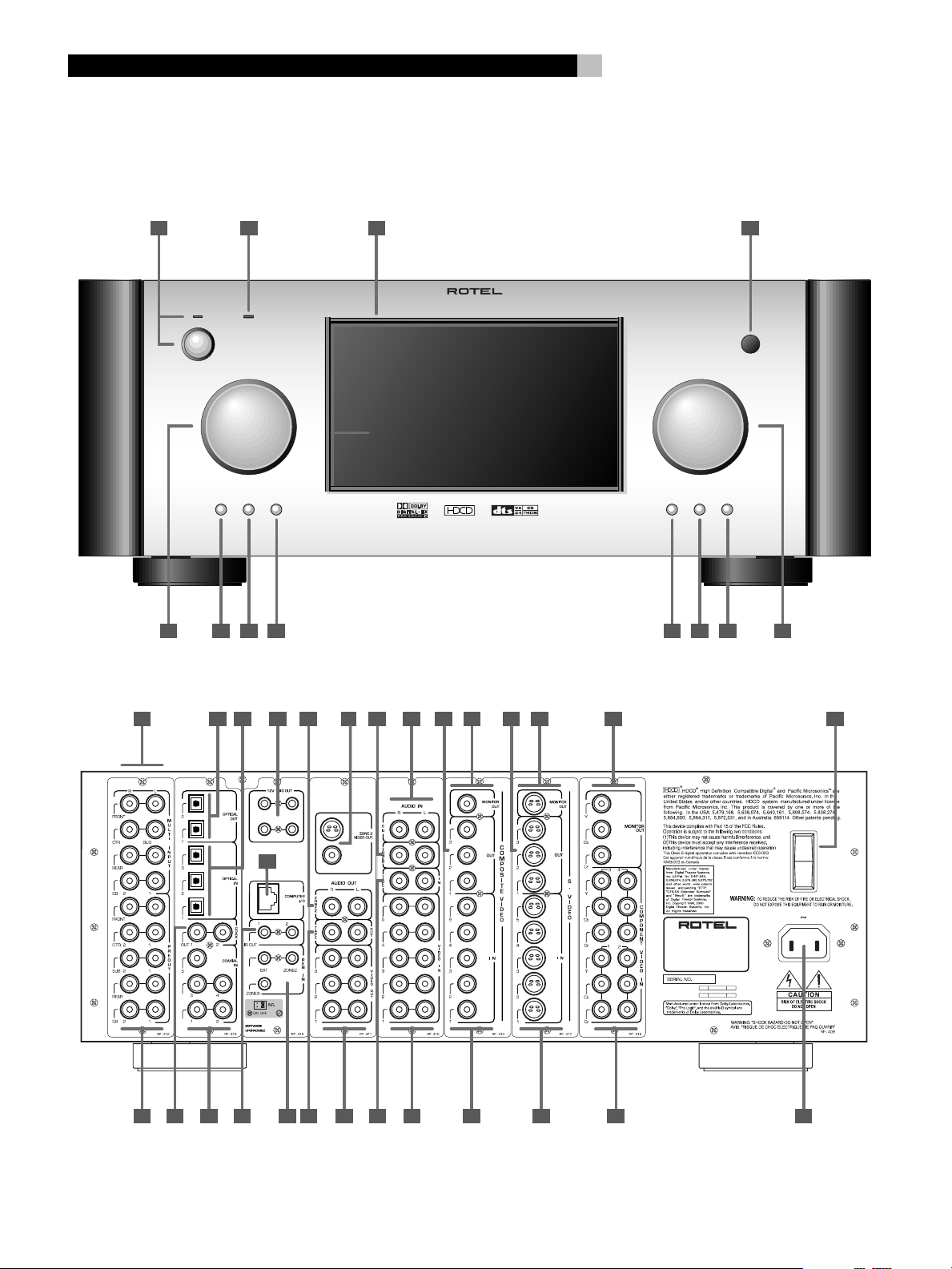
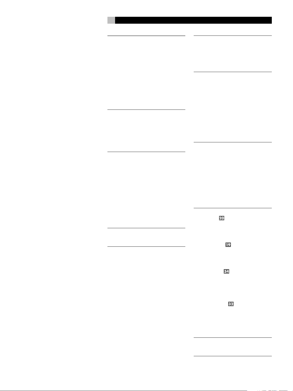
1: Front and Rear Panels
Faces Avant et Arrière
Paneles Frontal y Posterior
STANDBY ZONE 2
FUNCTION VOLUME
PUSH
PATH SPEAKER
6
431 2
SURROUND SOUND PROCESSOR RSP-1098
MODE DISPLAY MENU MUTE
5 126 7 8 9 10 11
13 14 15 2016 17
3 ZONE2
12
40
19 2221 24 2523
18
S-VIDEO
COMPOSITE
SURROUND SOUND PROCESSOR
MODEL NO: RSP-1098
POWER CONSUMPTION: 70 WATTS
26
POWER
ON
OFF
27 2928 30 32
343331 35 383736 39
Page 7
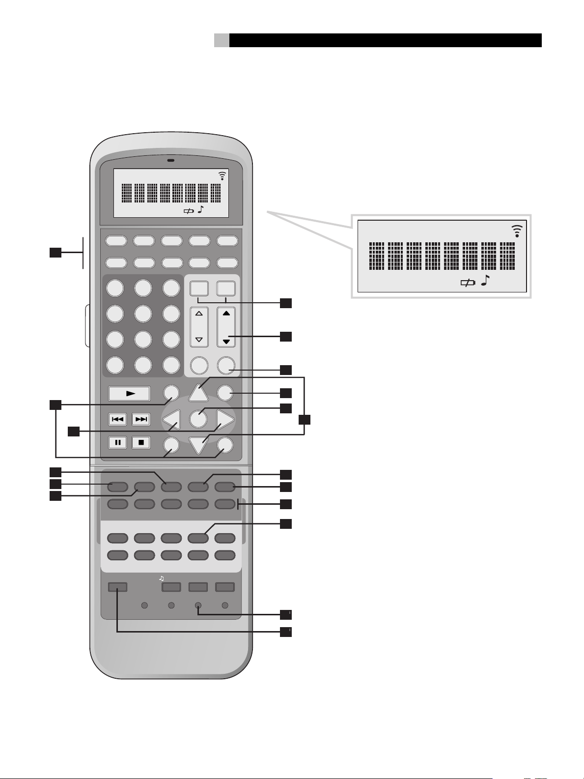
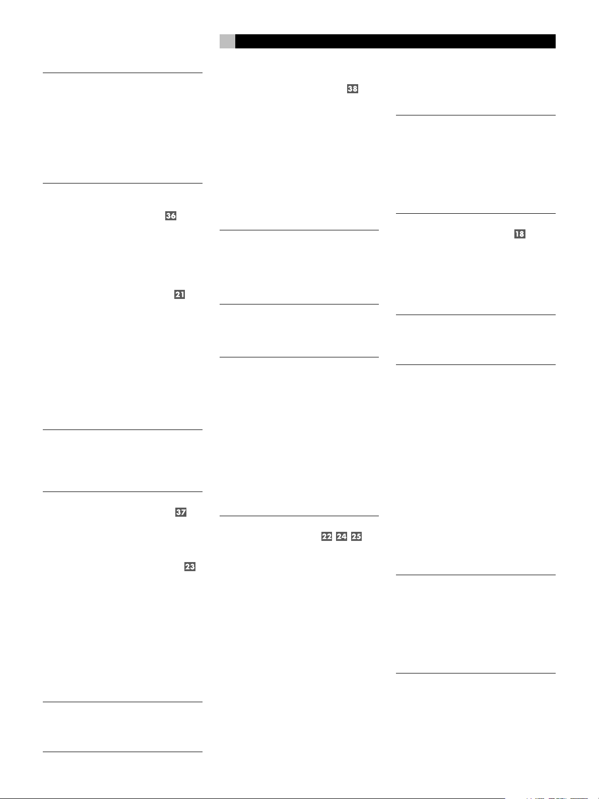
2: RR-1050 Remote
Télécommande RR-1050
Mando a Distancia RR-1050
REPTCLONE LOADING RECEIVERTRANSMITTER
AUD CD TUN
A
V1 V2 V3 V4 V5
123
4
7
+10
FRQ DIRECT
B
C
D
E
F
TUNE PRESET
FM MONO
CD
EQ
2CH PL C PL M 5CH 7CH
PROG RANDOM REPEAT
DISPLAY AUDIO ANGLE
DISP
RESUME REPEAT A -B
SCAN PTY
INPUT 1 INPUT 2 INPUT 3
DVD
POWER LEARNEDIT/ CLONE
DEVICE / INPUT
56
89
0
BAND
DISC 2DISC 1
DYN
TAPE2 PHONO TONE D-SLT
7
WAITINGLEARNEDIT
TAPE EXT
POWER
ON OFF
CH VOL
MACRO
M MUTE
X
GUIDE MENU
CM
UP
OSDCTR
ENT
-
SEARCH –
S
SUB
DISC 3 DISC 4 DISC 5
REC
SBTITLE
P-TUN
TV/VCR RECORD
+
SEARCH +
DWN
ZONE SUR+
GOTO
R
SUR
DISC+DISC-
ZOOM
SLOW
TA
TP
REPTCLONE LOADING RECEIVERTRANSMITTER
WAITINGLEARNEDIT
G
H
I
J
K
L
M
N
O
P
LANG
CLEAR RESETPRELOAD
PAGE 1/2
Q
R
Page 8
RSP-1098
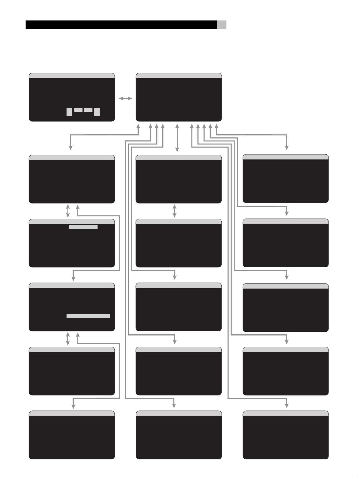
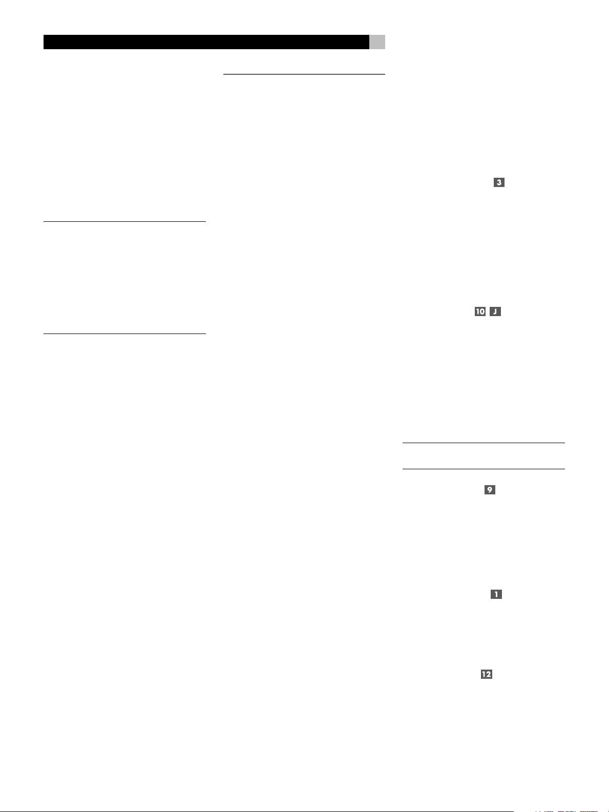
3: On-Screen Display/TFT Screen Menus
Menus On-Screen Display/Ecran TFT
Sistema de Visualización en Pantalla/Menús de la Pantalla TFT
8
SYSTEM STATUS
LISTEN:Tuner
VID INPUT:Video 1
RECORD:Source
MODE:Dolby Digital
INPUT:Coaxial 2
VOLUME:65
ZONE 2:Off
SPEAKERS:FL CNT SUB FR
SL CB1 CB2 SR
INPUT SETUP
LISTEN:CD
VID INPUT:Video 1
INPUT LABEL:_______
INPUT:Coaxial 2
CINEMA EQ:Off
12V TRIGGER:1
DEFAULT MODE:Dolby 3 Stereo
GROUP DELAY:200ms
MAIN MENU
INPUT SETUP
LISTEN:Multi Input
VID INPUT:Video 1
INPUT LABEL:_______
12V TRIGGER:1
LFE REDIRECT:On
MAIN MENU
MAIN MENU
INPUT SPEAKER
DELAY TEST TONE
SUB SETUP ZONE 2
DISPLAY CONTOUR
OTHER DEFAULT
EXIT
SPEAKER SETUP
FRONT:Large
CENTER:Large
SURROUND:Large
CENTER BACK:Large1
SUBWOOFER:Yes
ADVANCED:Enter
MAIN MENU
ADV SPEAKER SETUP
SPEAKER:Front
CROSSOVER:100Hz
DOLBY:Small
DTS:Small
STEREO/MPEG:Large
MUSIC:Small
SPEAKER SETUP MENU
CONTOUR SETUP
SPEAKER:Front
DEFEAT:On
HF CONTOUR:+5
LF CONTOUR: 0
MAIN MENU
DISPLAY OPTIONS
DISPLAY SOURCE:Off
CONTRAST:+ 5
BRIGHTNESS:- 5
PROGRESSIVE:V1+V2
OSD OUTPUT: SCREEN+MON
MAIN MENU
INPUT SETUP
LISTEN:CD
VID INPUT:Video 1
INPUT LABEL:_______
INPUT:Coaxial 2
CINEMA EQ:Off
12V TRIGGER:1
DEFAULT MODE:Dolby PLII Cinema
GROUP DELAY:200mS
MAIN MENU
OPTION
DOLBY PRO LOGIC II
MODE:Music
OPTIONAL PARAMETERS
PANORAMA:Off
DIMENSION:3
CENTER WIDTH:0
INPUT SETUP MENU
DTS Neo:6
MODE:Cinema
INPUT SETUP MENU
SUBWOOFER SETUP
CROSSOVER:100hZ
DOLBY DIGITAL: 0dB
DOLBY PL II: 0dB
DTS: 0dB
STEREO/MPEG:+ 2dB
MUSIC: Off
MULTI INPUT:- 2dB
MAIN MENU
TEST TONE
LEFT:+ 1dB
CENTER:- 1dB
RIGHT:+ 2dB
R SURROUND:+ 5dB
R CTR BACK:+ 2dB
L CTR BACK:+ 2dB
L SURROUND:+ 4dB
SUBWOOFER:+ 9dB
MAIN MENU
DELAY SETUP
LEFT: 12ft 3.6m
CENTER: 11ft 3.3m
RIGHT: 11ft 3.3m
R SURROUND: 6ft 1.8m
R CTR BACK: 8ft 2.4m
L CTR BACK: 9ft 2.7m
L SURROUND: 5ft 1.5m
SUBWOOFER: 5ft 1.5m
MAIN MENU
OTHER OPTIONS
RECORD:Source
TURN ON VOL:Last
MAX VOL:Max
VOL SPEED:Slow
POWER:Standby
LANGUAGE:English
VIDEO:NTSC
MAIN MENU
ZONE2 SETUP
SOURCE:Off
VOLUME SETUP:Variable
VOLUME:60
TURN ON VOL:Last
MAX VOL:Max
12V TRIGGER:Off
MAIN MENU
DEFAULT SETUP
FACTORY DEFAULT:No
USER DEFAULT:No
SET USER DEFAULT:No
MAIN MENU
Page 9
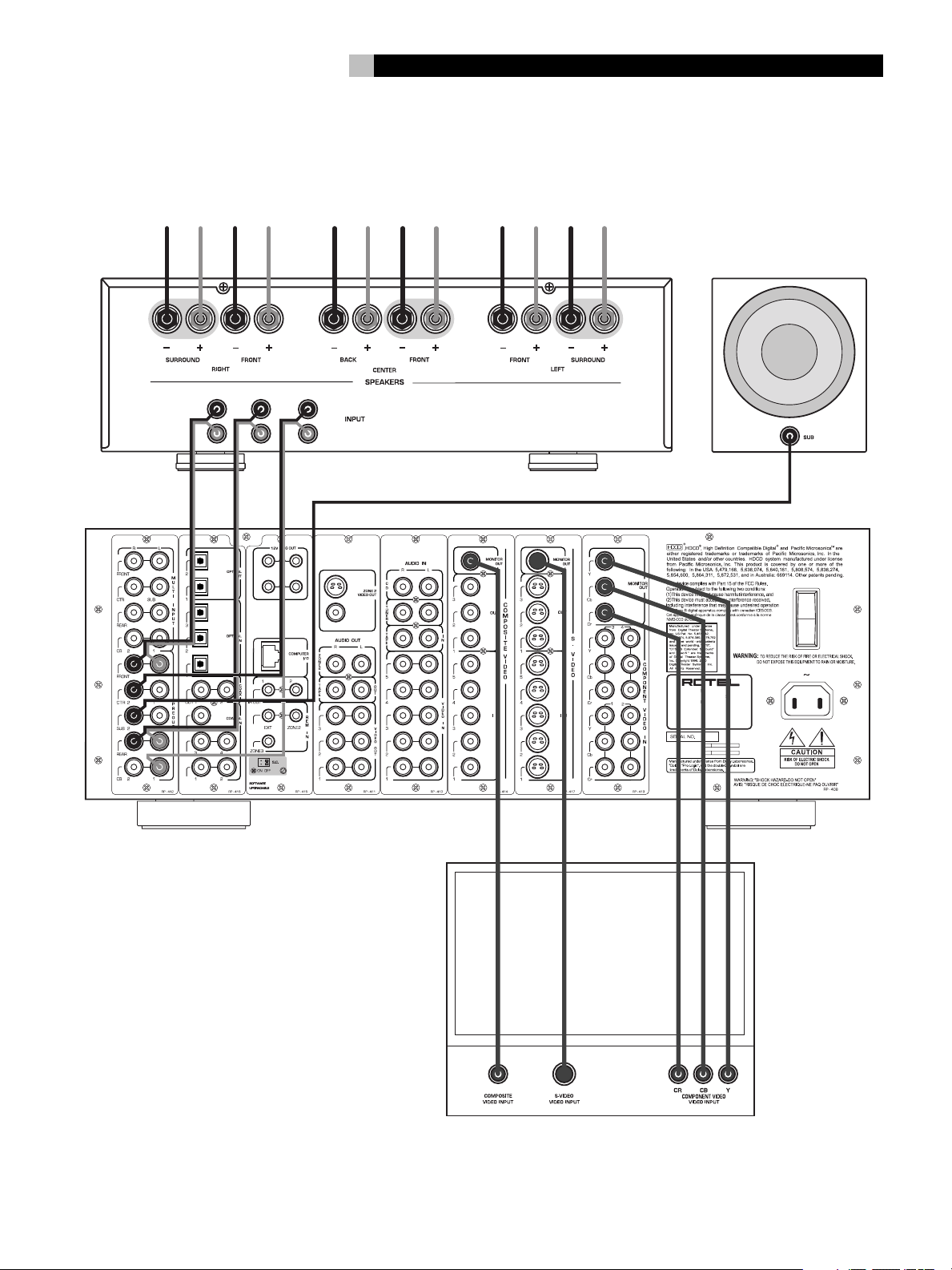
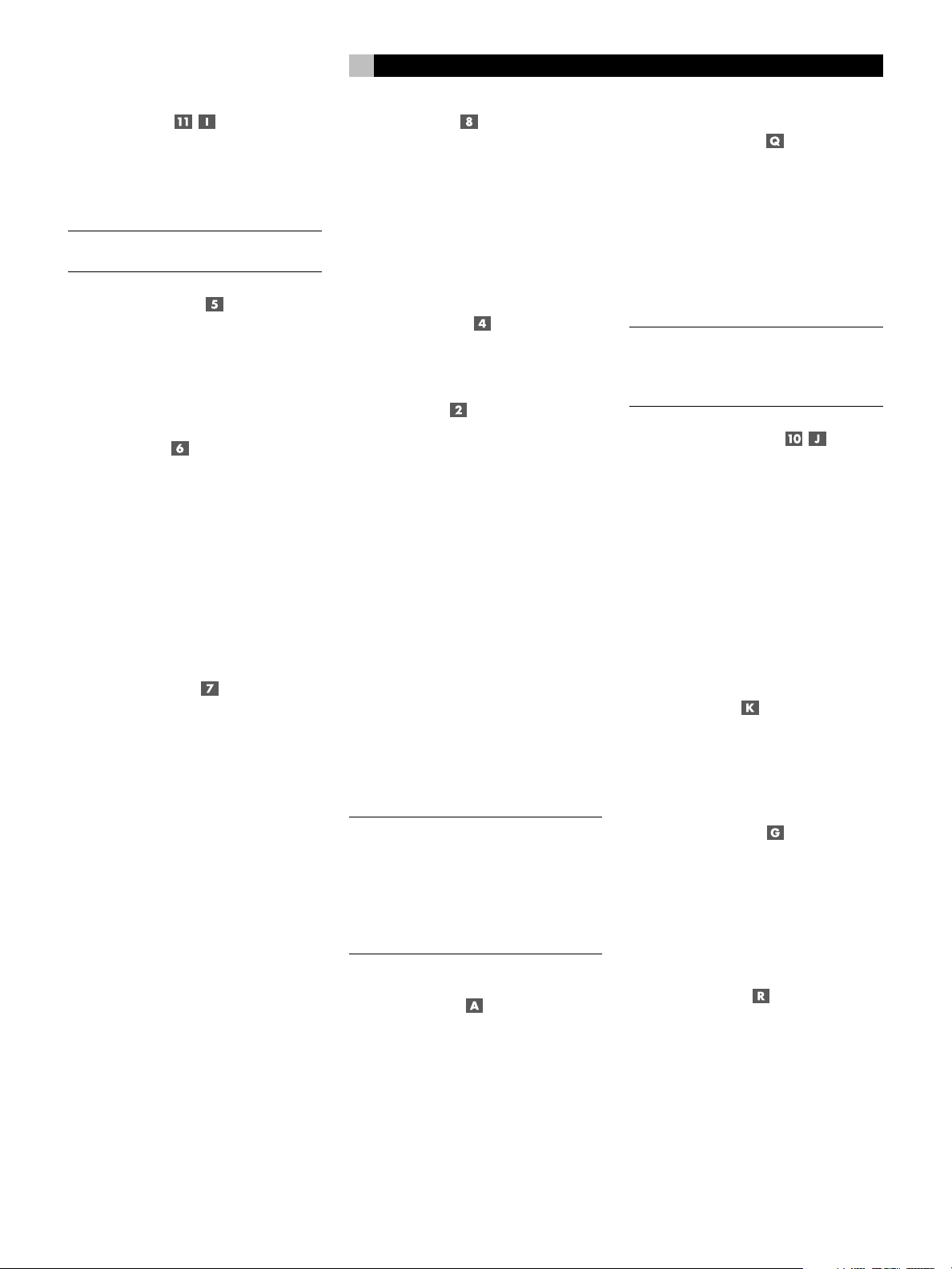
4: Outputs
Connexions de Sortie
Salidas
9
AMPLIFIER
SURROUND
FRONT
R
L
CENTER
CENTER
BACK
SUBWOOFER
RSP-1098
3 ZONE2
12
S-VIDEO
COMPOSITE
SURROUND SOUND PROCESSOR
MODEL NO: RSP-1098
POWER CONSUMPTION: 70 WATTS
POWER
ON
OFF
TV
Page 10
RSP-1098
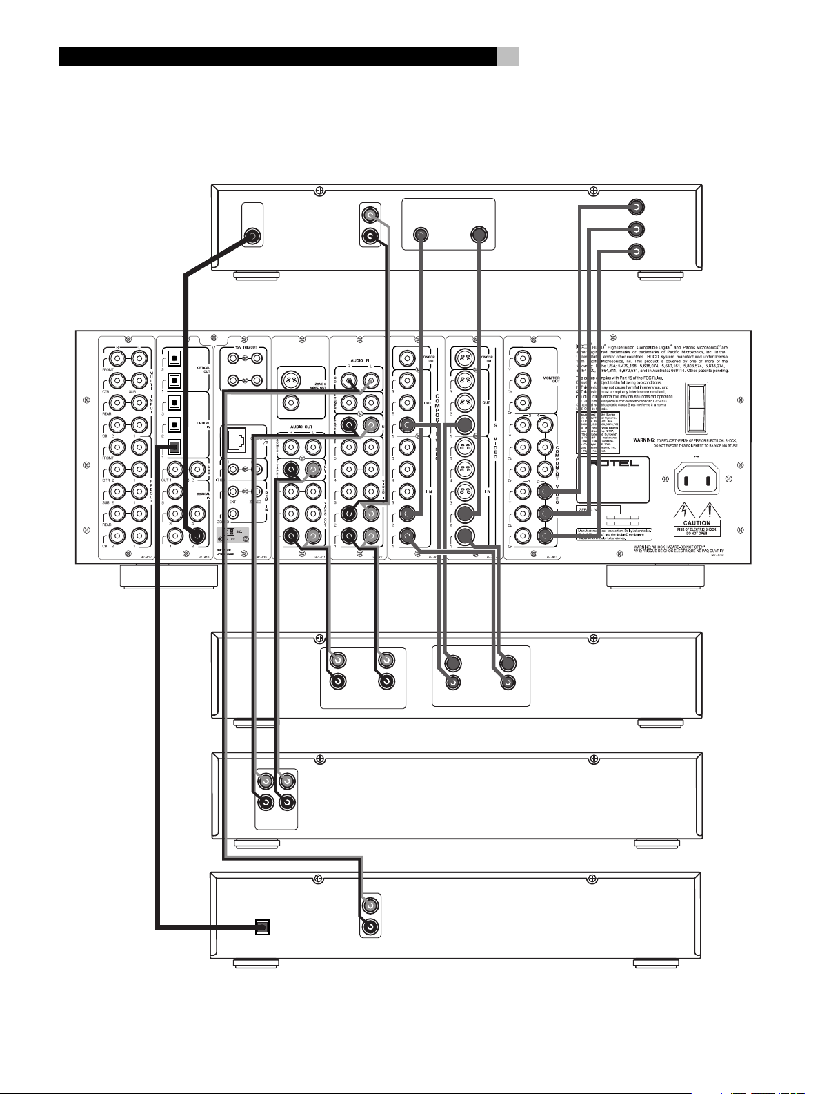
5: Source Connections
Connexions d'Entrée
Conexiones de las Fuentes
10
DVD
DIGITAL
OUTPUT
3 ZONE2
12
S-VIDEO
COMPOSITE
VIDEO
L
R
AUDIO
OUTPUT
OUTPUTS
S-VIDEOCOMPOSITE
Y
R
C
CB
COMPONENT
VIDEO
RSP-1098
POWER
ON
OFF
SURROUND SOUND PROCESSOR
MODEL NO: RSP-1098
POWER CONSUMPTION: 70 WATTS
LINE
OUT
OPTICAL
DIGITAL OUTPUT
VCR
L
R
REC
IN
AUDIO
LINE
OUT
REC
VIDEO
IN
LINE
OUT
S-VIDEO
COMPOSITE
TAPE
L
R
REC
IN
CD
L
R
ANALOG
OUTPUT
Page 11
SURROUND SOUND PROCESSOR
MODEL NO: RSP-1098
POWER CONSUMPTION: 70 WATTS
ON
OFF
POWER
S-VIDEO
COMPOSITE
3 ZONE2
12
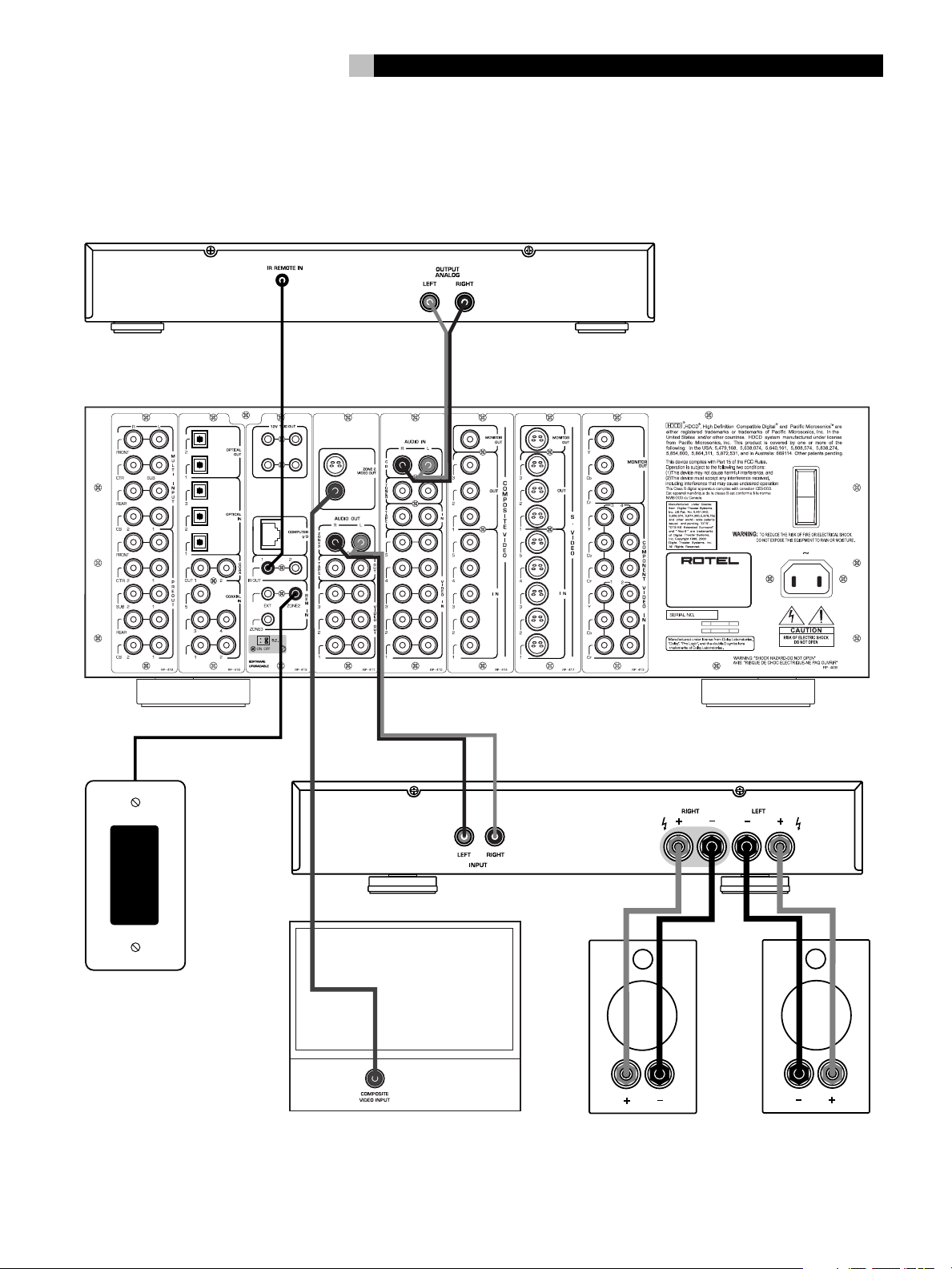
6: Zone 2 Connections
Connexions Zone 2
Conexiones de la Zona 2
11
CD
ROTEL RSP-1098
ZONE 2 IR
AMPLIFIER
LEFTRIGHT
Page 12
RSP-1098 Surround Sound Processor
12
Contents
Boxed numbers refer to RSP-1098 illustration.
Boxed letters refer to RR-1050 illustration.
Important Safety Instructions ................. 3
1: Front and Rear Panels ................................... 6
2: RR-1050 Remote ...........................................7
3: On-Screen Display/TFT Screen Menus ............. 8
4: Outputs ......................................................... 9
5: Source Connections ...................................... 10
6: Zone 2 Connections ..................................... 11
About Rotel .........................................14
Getting Started ....................................14
Video features ................................................. 14
Audio features ................................................. 14
Surround features............................................ 14
Other features ................................................. 14
Unpacking ....................................................... 15
Placement ....................................................... 15
CONNECTIONS 15
Analog Audio Inputs & Outputs ............15
CD Inputs .................................................. 15
Tuner Inputs .............................................. 15
TAPE Inputs ...............................................15
TAPE Outputs ............................................ 15
VIDEO 1–5 Audio Inputs ........................... 16
VIDEO 1–3 Audio Outputs ......................... 16
MULTI Inputs ............................................. 16
Preamp Outputs ........................................ 16
ZONE 2 Audio Outputs ............................... 16
Video Inputs & Outputs ........................16
VIDEO 1–5
Composite Video Inputs ............................. 17
VIDEO 1–3
Composite Video Outputs ........................... 17
VIDEO 1–5
S-Video Inputs ...........................................17
VIDEO 1–3
S-Video Outputs ........................................ 17
VIDEO 1–4
Component Video Inputs ........................... 17
TV Monitor Outputs ...................... 17
ZONE 2 Video Outputs ............................... 17
Digital Audio Input & Outputs ...............17
Digital Inputs ..................................... 18
Digital Outputs ................................... 18
Other Connections ................................18
AC Input ................................................... 18
Master Power Switch ................................. 18
12V TRIGGER Connections ......................... 18
REM IN Jacks ............................................ 18
IR OUT Jacks ............................................. 18
Computer I/O ........................................... 18
Making Connections.............................. 19
CD Player ........................................................ 19
DVD Player ...................................................... 19
Cable, Satellite, or HDTV Tuner......................... 19
AM/FM Tuner .................................................. 19
Audio Tape Recorder ........................................ 19
VCR or Digital Video Recorder .......................... 19
DVD-A or SACD Player ..................................... 19
TV Monitor....................................................... 20
Amplifiers and Powered Subwoofers................. 20
OPERATING THE RSP-1098 20
Front Panel Overview ..........................20
Color TFT Display ...................................... 20
MENU button ...................................... 20
DISPLAY Button ......................................... 20
STANDBY Button ....................................... 20
VOLUME Knob ........................................... 20
MUTE Button ...................................... 21
FUNCTION Knob ........................................ 21
PATH Button .............................................. 21
SPEAKER Button ........................................ 21
MODE Button ............................................ 21
Remote Sensor .......................................... 21
ZONE 2 LED .............................................. 21
Remote Control Overview ....................21
Using the RR-1050
AUDIO Button ........................................... 21
Programming the RR-1050
PRELOAD Button ....................................... 21
MENU/OSD button ............................. 21
ENTER Button ............................................ 21
ON/OFF Buttons ....................................... 21
POWER Button .......................................... 21
VOLUME Button ......................................... 22
MUTE Button ...................................... 22
DEVICE/INPUT Buttons .............................. 22
REC Button ................................................22
ZONE Button ............................................. 22
UP/DOWN Buttons .................................... 22
+/– Buttons ............................................. 22
Speaker Selection Buttons ......................... 22
EQ Button ................................................. 22
TONE Button ............................................. 22
Surround Mode Buttons ............................. 22
SUR+ Button .............................................22
DYN Button ...............................................22
Page 13
13
English
Basic Operations .................................. 22
Power and Standby On/Off ......... 22
Volume Adjustments ........................... 23
Muting the Sound ............................... 23
Display Options .................................. 23
Selecting Inputs....................................23
Selecting a Source Input
from the Front Panel .......................... 23
Selecting a Source
from the Remote ......................... 24
Overview of Surround Formats .............24
Dolby Surround
Dolby Pro Logic II ............................................ 24
Dolby Digital ................................................... 24
DTS 5.1
DTS 96/24 ...................................................... 24
DTS Neo:6 ....................................................... 25
6.1 and 7.1 Surround ...................................... 25
DSP Music Modes ............................................. 25
2Ch/5Ch/7Ch Stereo Formats.......................... 25
Other Digital Formats ...................................... 26
Automatic Surround Modes ...................26
Other Settings...................................... 29
Temporary Speaker Level ..... 29
Temporary Group Delay ........ 29
Dynamic Range ........................... 29
Contour/Tone Settings ........................ 29
Cinema EQ ................................................ 30
Zone 2 Operation .................................30
Zone 2 Power On/Off Operation ............... 30
Controlling Zone 2 from the Front Panel .......... 30
Controlling Zone 2
from the Remote Location ........... 30
SETUP 31
Menu Basics .........................................31
Navigation Buttons ............... 31
System Status .................................................. 31
Main Menu ...................................................... 32
Display Options................................................ 32
Configuring Inputs ................................32
Input Setup...................................................... 32
Multi Input Setup ............................................. 33
Miscellaneous Settings ......................... 38
Other Options .................................................. 38
Zone 2 Setup ................................................... 39
Default Setup .................................................. 39
MORE INFORMATION 40
Troubleshooting ....................................40
Specifications .......................................41
Audio .............................................................. 41
Video............................................................... 41
General ........................................................... 41
Manually Selecting Surround Modes ......26
Dolby Digital 5.1
Dolby Digital Surround EX ............................... 27
Dolby Digital 2.0 ............................................. 27
DTS 5.1
DTS 96/24
DTS-ES 6.1....................................................... 27
MPEG Multichannel .......................................... 28
Digital Stereo
(PCM, MP3, and HDCD) ................................... 28
Analog Stereo ..................................................28
Dolby Pro Logic II ............................................ 34
DTS Neo:6 ....................................................... 34
Configuring Speakers and Audio ............34
Understanding Speaker Configuration .............. 34
Speaker Setup ................................................. 35
Advance Speaker Setup.................................... 36
Subwoofer Setup ............................................. 36
Test Tone ......................................................... 37
Delay Setup ..................................................... 38
Contour Setup.................................................. 38
Page 14

RSP-1098 Surround Sound Processor
14
About Rotel
A family whose passionate interest in music
led them to manufacture high fidelity components of uncompromising quality founded Rotel
40 years ago. Through the years that passion
has remained undiminished and the family goal
of providing exceptional value for audiophiles
and music lovers regardless of their budget,
is shared by all Rotel employees.
The engineers work as a close team, listening to, and fine tuning each new product until
it reaches their exacting musical standards.
They are free to choose components from
around the world in order to make that product the best they can. You are likely to find
capacitors from the United Kingdom and
Germany, semi conductors from Japan or the
United States, while toroidal power transformers
are manufactured in Rotel’s own factory.
Rotel’s reputation for excellence has been
earned through hundreds of good reviews and
awards from the most respected reviewers in
the industry, who listen to music every day.
Their comments keep the company true to its
goal - the pursuit of equipment that is musical, reliable and affordable.
All of us at Rotel, thank you for buying this
product and hope it will bring you many years
of enjoyment.
Getting Started
Thank you for purchasing the Rotel RSP-1098
Surround Sound Processor. The RSP-1098 is
full-featured audio/video control center for
analog and digital source components. It features digital processing for a wide range of
formats including Dolby Surround
®
, DTS® and HDCD® source material.
Digital
Video features
• Front panel widescreen color TFT screen
for video or operating menus.
• Wideband 100 mHz video processing for
HDTV signals.
• Full complement of composite, S-Video, and
Component Video inputs and outputs
• Conversion of composite and S-Video signals to Component Video for output to TV
monitor.
Audio features
• Rotel’s Balanced Design Concept combines
advanced circuit board layout, comprehensive parts evaluation, and extensive listening
tests for superior sound and reliability.
• Individual circuit boards grouped by function for maximum signal isolation.
• 24-bit/128x oversampling analog-to-digital
converters from AKM and Crystal Semiconductor 24-bit/192 kHz digital-to-analog
converters
®
, Dolby
Surround features
• Automatic Dolby Digital® decoding for
Dolby Digital
Dolby Digital Surround EX
• Dolby
Surround
be optimized for Music or Cinema sources
plus an emulation mode for the original
Dolby Pro Logic decoding.
• Automatic decoding for DTS
DTS-ES
crete 6.1 channel, and DTS 96/24 digital recordings.
• DTS
ing surround channels for 5.1, 6.1 or 7.1
channel systems from 2-channel stereo or
matrix surround recordings. Can be optimized for Music or Cinema sources.
• Automatic decoding for MPEG Multichannel
digital recordings.
• Rotel XS (eXtra Surround) automatically ensures proper decoding and optimum performance from any multichannel digital
signal on 6.1 and 7.1 channel systems.
Always active in any system with center
back speaker(s), Rotel XS even works with
signals that would not otherwise activate
the proper decoding (such as non-flagged
DTS-ES and Dolby Surround EX discs) or
for which there is no extended surround
decoder (such as DTS 5.1, Dolby Digital
5.1, and even Dolby Pro Logic II decoded
Dolby Digital 2.0 recordings).
®
2.0, Dolby Digital® 5.1, and
®
Pro Logic II® decoding for Dolby
®
matrix encoded recordings. Can
®
Matrix 6.1 channel, DTS-ES® Dis-
®
Neo:6® Surround modes for deriv-
®
recordings.
®
5.1 channel,
“DTS”, “DTS-ES Extended Surround”, “DTS ES® Matrix 6.1”,
and “DTS ES® Discrete 6.1”, and “DTS Neo:6®”are
trademarks of Digital Theater Systems, Inc.
Manufactured under license from Dolby Laboratories.
“Dolby”, “Pro Logic”, “Surround EX”, and the double-D
symbol are trademarks of Dolby Laboratories.
, HDCD®, High Definition Compatible Digital ® and
Pacific Microsonics™ are either registered trademarks or
trademarks of Pacific Microsonics, Inc. in the United States
and/or other countries. HDCD system manufactured under
license from Pacific Microsonics, Inc. This product is covered
by one or more of the following: In the USA: 5,479,168,
5,638,074, 5,640,161, 5,808,574, 5,838,274,
5,854,600, 5,864,311, 5,872,531, and in Australia:
669114. Other patents pending.
• Analog bypass mode for pure 2-speaker
stereo with no digital processing.
• Optical and coax digital inputs and outputs.
• MULTI Input for 7.1 channel analog signals
from DVD-A and SACD players. Subwoofer
options include .1 channel pass through
or bass redirect feature with an analog lowpass filter for a summed subwoofer output
from seven channels.
®
• Automatic HDCD
High Definition Compatible Digital
decoding for signals from
®
com-
pact discs.
• Automatic decoding of digital signals from
MP3 (MPEG-1 Audio Layer 3) players.
• Surround modes for playback of surround
sound material on 2 channel and 3 channel systems for total compatibility.
• Four DSP Music modes.
Other features
• Multi-zone, multi-source capability with
independent input selection and volume.
• User friendly ON-SCREEN DISPLAY (OSD)
menu system with programmable labels for
all inputs. Choice of languages.
• Learning remote control to operate the
RSP-1098 and nine other components.
• Upgradeable microprocessor software to
accommodate future upgrades.
• Four assignable 12V trigger outputs for
remote turn-on of power amplifiers and other
components.
Page 15
15
English
Unpacking
Remove the unit carefully from its packing. Find
the remote control and other accessories. Save
the box as it will protect the RSP-1098 if you
move or need to return it for maintenance.
Placement
Place the RSP-1098 on a solid, level surface
away from sunlight, heat, moisture, or vibration. Make sure that the shelf can support the
weight of the unit.
Place the RSP-1098 close to the other components in your system and, if possible, on its
own shelf. This will make initial hookup, and
subsequent system changes easier.
The RSP-1098 can generate heat during normal operation. Do not block ventilation openings. Allow a minimum of 10 cm (4 inches)
of unobstructed space around the unit. If installed in a cabinet, make sure that there is
adequate ventilation.
Don’t stack other components or objects on
top of the RSP-1098. Don’t let any liquid fall
into the unit.
CONNECTIONS
Although, the RSP-1098’s rear panel looks
daunting, connecting the unit to your system
is straightforward. Each of the source components in the system are connected to the
RSP-1098 inputs with a pair of standard RCA
cables for analog audio, a video connection
(composite, S-Video, or Component Video),
and an optional digital audio cable (coax or
optical).
NOTE
: Surround formats like Dolby Digital and
DTS are digital formats and the RSP-1098
can only decode them when a digital input
signal is available. For this reason, you should
always connect your DVD player’s digital
outputs to the RSP-1098, using either the optical or coax inputs.
The outputs of RSP-1098 are sent to the power
amplifier(s) with standard RCA cables from
preamp audio outputs. The video signal from
the RSP-1098 is sent to the TV monitor using
composite video, S-Video, or Component Video
connections.
In addition, the RSP-1098 has MULTI input connections for a source component that does its
own surround decoding, remote IR sensor
inputs, and 12V trigger connections for remote
turn-on of other Rotel components.
NOTE
: Do not plug any system component
into an AC source until all connections have
been properly made.
NOTE
: Each source input must be properly
configured using the INPUT SETUP menu of
the OSD menu system. We recommend going to this menu after connecting each source
to configure it as desired. See Input Setup of
the Setup section for information.
Analog Audio Inputs &
Outputs
The following connections are used for connecting analog audio signals to and from the
RSP-1098. See the
for specific instructions on connecting each type
of component.
NOTE
: Normally, the RSP-1098 converts ana-
log inputs to digital signals. All of the digital
processing is available including bass management, digital crossovers, speaker level and
delay settings and a number surround mode
options including 2-ch stereo, Dolby Pro Logic
II, etc. Alternatively, there is an analog bypass surround mode that routes 2-ch analog
inputs directly to the Volume control and
preamp outputs, bypassing the digital processing entirely for pure analog stereo.
Making Connections
CD Inputs
A left/right pair of RCA analog audio inputs
for connecting a CD player.
Tuner Inputs
topic
Video cables should have a 75 ohm impedance. The S/PDIF digital audio interface standard also specifies a 75 ohm impedance and
all good digital cables adhere to this requirement. Do NOT substitute conventional audio
interconnect cables for digital or video signals.
Standard audio interconnects will pass these
signals, but their limited bandwidth reduce performance.
When making signal connections, connect LEFT
channels to LEFT channel jacks and RIGHT channels to RIGHT channel jacks. All RCA-type
connections on the RSP-1098 follow these standard color codes:
Left channel audio: white RCA jack
Right channel audio: red RCA jack
Composite video: yellow RCA jack
A left/right pair of RCA analog audio inputs
for connecting an AM/FM tuner.
TAPE Inputs
A pair of RCA inputs, labeled TAPE IN, for
connecting the left/right analog audio signals
from an audio tape deck or recording device.
TAPE Outputs
A pair of RCA inputs, labeled TAPE OUT, for
sending left/right line level analog audio signals for recording on a tape deck or recording device.
NOTE
: These outputs should be connected to
the inputs of the same tape deck connected
to the TAPE IN inputs.
Page 16

RSP-1098 Surround Sound Processor
16
VIDEO 1–5 Audio Inputs
Five pair of RCA inputs, labeled AUDIO IN
(VIDEO IN 1 – 5), provide connections for left/
right analog audio signals from five additional
source components. These inputs have corresponding video inputs and are used for VCRs,
satellite TV tuners, DVD players, etc. However,
they may also be used for additional audio
only components, simply omitting the corresponding video connections.
VIDEO 1–3 Audio Outputs
Three pair of RCA jacks, labeled AUDIO OUT
(VIDEO OUT 1 – 3), provide connections for
sending line level left/right line level analog
audio signals for recording to a VCR.
These connections correspond to the VIDEO
IN 1–3 connections. Make sure that you are
consistent. If you hook up a particular VCR to
the VIDEO 1 inputs, hook up the VIDEO 1 outputs to the same VCR.
NOTE
: There are no analog audio outputs for
VIDEO 4 & 5. Therefore, in an elaborate system, hook up all of the VCRs and recording
devices to VIDEO 1–3 and use VIDEO 4 & 5
for playback only components.
NOTE
: Video 1–3 can be used for audio-only
tape decks, simply omitting the corresponding video connections.
MULTI Inputs
A set of RCA inputs accept up to 7.1 channels of analog signals from a DVD-A or SACD
player. There are inputs for FRONT L & R,
CENTER, SUB, REAR L & R, and CENTER BACK
1 & 2.
These inputs bypass all digital processing in
the RSP-1098 and are routed directly to the
Volume control and preamp outputs
There are two subwoofer options for the MULTI
input. Normally, the .1 channel input is passed
through directly to the subwoofer output. An
optional bass redirect feature duplicates the
7 main channels, sums them, and sends this
mono signal through a 100 Hz analog low
filter to the subwoofer output. This provides
an unaltered analog bypass for the seven main
channels along with a subwoofer signal derived from those channels.
Preamp Outputs
A group of ten RCA analog audio outputs sends
the RSP-1098’s line level output signals to
external amplifiers and powered subwoofers.
These outputs are variable level, adjusted by
the RSP-1098 volume control. The eight connectors provide output for: FRONT L & R, CENTER 1 & 2, SURROUND L & R, CENTER BACK
CB1 & CB2, and SUBWOOFER 1 & 2.
NOTE
: Depending on your system configura-
tion, you may use some or all of these connections. For example, if you only have one
center channel, connect it to the CENTER 1
output. If you only have one center back channel, connect it to the CB1 output.
ZONE 2 Audio Outputs
A pair of RCA inputs, labeled AUDIO OUT/
ZONE 2, sending analog audio signals to an
external amplifier for a remote zone. These
outputs can be configured as either fixed or
variable level using the ZONE 2 SETUP menu.
NOTE
: Only analog input signals are avail-
able at the Zone 2 outputs. Source components connected to only the digital inputs are
not available in Zone 2.
To configure your system for Zone 2 operation, connect the left and right Zone 2
on the RSP-1098 to the left and right channel
inputs
of the amplifier powering the remote
speakers, using standard RCA audio cables.
outputs
Video Inputs & Outputs
These connections are used for connecting
video signals to and from the RSP-1098. See
Making Connections
the
instructions for each type of component.
The RSP-1098 provides Composite, S-Video,
and Component Video connections. Composite
video connections simplify system configuration; however, S-Video connections typically
provide better picture quality. Component Video
connections are required for HDTV or progressive scanned DVD video. Be aware of the following implications for the configuration of your
system:
On Screen Display: The RSP-1098 OSD
system is available on the TV monitor, regardless
of what type of connection is made from the
TV MONITOR outputs to the TV set. The OSD
system is also available in the TFT screen.
section for specific
NOTE
: When using a progressive scan or 1080i
video signal from the Component Video inputs, the TV monitor cannot display the video
signal and the OSD menus at the same time.
A “progressive” setting in the Display Options
setup menu allows the use of the main OSD
setup menus, even with progressive or HDTV
signals. When the main OSD setup menus are
activated, the progressive scan video input is
interrupted and restored when the OSD menus
are cancelled. The temporary OSD information displays (such as volume setting, etc.) are
not displayed. All of the OSD displays are available on the front-panel TFT screen.
Output Conversion: The RSP-1098 converts composite and S-Video signals to Component Video signals for output to an NTSC
or PAL standard TV monitor. For maximum convenience, connect the RSP-1098 to the TV monitor with Component Video connections. S-Video
signals cannot be converted to composite outputs and vice versa.
NOTE
: When a video input or inputs are se-
lected for progressive mode on the DISPLAY
OPTIONS menu, the conversion from composite or S-Video to Component Video output is not available for those inputs. The
conversion from composite or S-VIDEO to
Component Video output is only available for
the other video inputs.
Many digital HDTV monitors adjust scan rates
and other video parameters depending on the
type of input connection. You may wish to make
multiple connections between the RSP-1098
and the TV monitor, switching inputs on the
TV to take advantage of these features.
TFT Display: If you choose to display video
signals on the front panel display, keep in mind
that it can only display signals from sources
connected with composite video connections.
Even if you use Component Video connections,
it is recommended that you also make composite video connections from each source
component to the RSP-1098 so that the signal from each source component can be displayed on the front panel TFT display.
Page 17
17
English
NOTE
: The TFT display cannot properly dis-
play progressive scan (480p) signals. When
a DVD player is outputting a progressive scan
signal on Component Video outputs, its composite video outputs may not provide a usable signal. In this case, the TFT screen will
not be able to display video from the DVD
player or may display distorted video, even
with a composite video connection.
VIDEO 1–5
Composite Video Inputs
Five inputs accepts standard composite video
signals from source components using standard 75 ohm RCA video cables.
VIDEO 1–3
Composite Video Outputs
Three RCA jacks, labeled COMPOSITE VIDEO
OUT 1–3, provide connections for sending
composite video signals for recording on a
VCR or other recording device.
These connections correspond to the VIDEO
IN 1–3 connections. Make sure that you are
consistent. If you hook up a particular VCR to
the VIDEO 1 inputs, hook up the VIDEO 1 output
to the same VCR.
NOTE
: The RSP-1098 cannot convert S-Video
or Component Video signals to composite
video. Therefore, only signals received at the
composite video inputs are available at these
outputs.
VIDEO 1–5 S-Video Inputs
Five inputs, labeled S-VIDEO IN 1–5 accept
S-Video signals from source components.
VIDEO 1–3 S-Video Outputs
Three S-VIDEO jacks, labeled S-VIDEO OUT
1–3, provide connections for sending S-Video
signals for recording on a VCR or other recording device.
These connections correspond to the VIDEO
IN 1–3 connections. Make sure that you are
consistent. If you hook up a particular VCR to
the VIDEO 1 inputs, hook up the VIDEO 1 output
to the same VCR.
NOTE
: The RSP-1098 cannot convert compos-
ite video or Component Video signals to
S-Video. Only signals received at the S-Video
inputs are available at these outputs.
VIDEO 1–4
Component Video Inputs
Component Video connections split the video
into three signals – luminance (Y) and separate chrominance (CB and CR) signals, allowing
delivery of a reference-quality picture with high
definition signals. Component Video connections should be used for progressive scan DVD
players and high-definition digital television
receivers. Each of these signals is carried by
a separate 75 ohm video cable with RCA
connectors.
NOTE
: In progressive scan mode, a DVD player
may not be able to output a usable video
signal on its composite video outputs. In this
case, the TFT screen will not be able to display video from the DVD player, even with a
composite video input.
Four sets of inputs, labeled COMPONENT
VIDEO IN 1–4 accept Component video signals from source components.
NOTE
: When using a progressive scan or
1080i HDTV video signal from the Component Video inputs, the TV monitor cannot display the video signal and the OSD menus at
the same time. A “progressive” setting in the
Display Options setup menu allows the use
of the main OSD setup menus, even with progressive or HDTV signals. When the main
OSD setup menus are displayed, the progressive video signal is interrupted and restored
when the OSD menus are cancelled. The temporary OSD information displays (such as volume setting, etc.) are not displayed.
TV Monitor Outputs
The TV MONITOR outputs of the RSP-1098
send the video signal to your TV monitor. Three
types of video output connections are provided
– RCA composite video, S-Video, and Component Video.
The composite video output only sends signals
from composite video inputs to the TV monitor. The S-Video output only sends signals from
S-Video video inputs to the TV. The Component Video output converts signals from ANY
type of source input to the TV. If you have
connected all of your source components with
the same type of connection, then you only
need to make one connection from the
RSP-1098 to the TV monitor. If you connect
the RSP-1098 to the TV monitor with Component Video connections, you also only need
to make one type of connection because composite and S-Video signals are converted to
Component Video.
NOTE
: When a video input or inputs are se-
lected for progressive mode on the DISPLAY
OPTIONS menu, the conversion from composite or S-Video to Component Video output is not available for those inputs. The
conversion from composite or S-VIDEO to
Component Video output is only available for
the other video inputs.
ZONE 2 Video Outputs
The ZONE 2 Video outputs of the RSP-1098
send the video signal to a TV monitor in the
remote zone. Two types of video output connections are provided – RCA composite video
and S-Video.
NOTE
: Only composite video input signals are
available at the Zone 2 composite video outputs. Only S-Video input signals are available at the Zone 2 S-Video video outputs.
Digital Audio
Input & Outputs
The RSP-1098 provides digital connections
which may be used in place of, or in addition to, the analog audio input and output connections described in the previous sections.
These connections include eight digital inputs
and four digital outputs for recording.
These digital connections can be used with
any source component that supplies a digital
signal, such as a DVD player, CD player, or
satellite TV tuner.
NOTE
: With a digital connection, the RSP-1098
will be used to decode the signal, rather than
the source component’s internal decoders. In
general, you must use digital connections for
a DVD player or other component that supplies a Dolby Digital or DTS signal; otherwise the RSP-1098 will not be able to decode
these formats.
Page 18

RSP-1098 Surround Sound Processor
18
Digital Inputs
The RSP-1098 accepts digital inputs from source
components such as CD players, satellite TV
tuners, and DVD players. The built-in digital
processor senses and adjusts to the correct sampling rates.
There are eight digital inputs on the rear panel,
five coaxial and three optical. These digital
inputs can be assigned to any of the input
sources using the INPUT SETUP screen during
the setup process. For example, you can assign the COAXIAL 1 digital input connector
to the VIDEO 1 source and the OPTICAL 2
digital input to the VIDEO 3 source.
NOTE
: When using digital connections, you
should also make the analog audio input connections described previously. The analog
connection is necessary to record to an analog recorder in some circumstances or for
ZONE 2 operation
Digital Outputs
The RSP-1098 has four digital outputs (two
coaxial and two optical) to send the digital
signal from any of the digital inputs to a digital recorder or outboard digital processor.
When a digital input source signal is selected
for listening, that signal is automatically sent
to both digital outputs for recording.
NOTE
: Only digital signals from source com-
ponents are available at these outputs. Analog signals cannot be converted and are not
available at the digital outputs.
Master Power Switch
The large rocker switch on the rear panel is a
master power switch. When it is in the OFF
position, power to the unit is completely off.
When it is in the ON position, the front panel
STANDBY and remote control ON/OFF buttons can be used to active the unit or put it
standby mode.
NOTE
: After all connections are completed,
the rear panel master power switch should
be put in the ON position and usually left in
that position.
12V TRIGGER Connections
Many Rotel amplifiers offer the option of turning
them on and off using a 12 volt trigger. These
four connections provide this 12 volt trigger
signal from the RSP-1098. When the RSP-1098
is activated, a 12 volt DC signal is sent to the
amplifiers to turn them on. When the RSP-1098
is put in STANDBY mode, the trigger signal
is interrupted and the amplifiers turn off.
To use the remote turn on feature, connect one
of the RSP-1098’s 12V TRIG OUT jacks to the
12 volt trigger input of a Rotel amplifier, using a cable with mono 3.5 mm mini-plugs on
both ends. The +12 V DC signal appears at
the “tip” connector.
NOTE
: The 12V Trigger outputs can be config-
ured to turn on only when specific input
sources are activated. See the Input Setup
and Zone 2 Setup menus in the Setup section
of this manual for details.
features of the RSP-1098 and can be relayed
to other components. Remote control signals
sent to the ZONE 3 REM IN can be used to
select the RECORDING source (the signal
available at the TAPE OUT connections).
Consult your authorized Rotel dealer for information on external receivers and the proper
wiring of a 3.5 mm mini-plugs to fit the REM
IN jacks.
NOTE
: The IR signals from the EXT REMOTE
IN jack (as well as those from the ZONE 2/
ZONE 3 REMOTE IN jacks) can be relayed
to source components using external IR emitters or hard-wired connections from the IR
OUT jacks. See the following section for additional information.
IR OUT Jacks
The IR OUT 1 & 2 jacks send IR signals received at the ZONE REM IN jacks or the EXT
REM IN jack to an infrared blaster or emitter
placed in front of a source component’s IR
sensor. In addition, the IR OUT can be hardwired to Rotel CD players, DVD players, or
tuners with a compatible connector.
These outputs are used to allow IR signals from
Zone 2 to be sent to the source components,
or to pass along IR signals from a remote in
the main room when the sensors on the source
components are blocked by installation in a
cabinet.
See your authorized Rotel dealer for information
on IR emitters and repeater systems.
Other Connections
AC Input
Your RSP-1098 is configured at the factory for
the proper AC line voltage in the country where
you purchased it (USA: 115 volts/60Hz AC
or CE: 230 volts /50 Hz AC ). The AC line
configuration is noted on a decal on the back
of your unit.
Plug the supplied cord into the AC INPUT
receptacle on the back of the unit.
NOTE
: Memorized settings and video labels
are preserved indefinitely, even if the
RSP-1098 is disconnected from AC power.
REM IN Jacks
Three 3.5 mm mini-jacks (labeled REM IN,
ZONE 2, and ZONE 3) receive command
codes from an industry-standard infrared receivers (Xantech, etc.), used when the IR signals from a hand held remote control cannot
reach the front panel IR sensor.
EXT: The EXT jack is used with an outboard
IR receiver to duplicate the front panel IR sensor. This feature is useful when the unit is installed in a cabinet and the front panel sensor is blocked or when IR signals need to be
relayed to other components.
ZONE 2 and ZONE 3: These two jacks are
used with IR repeater systems to receiver signals from IR control systems in remote locations. For example, remote control signals sent
to the ZONE 2 REM IN control the ZONE 2
Computer I/O
The RSP-1098 can be operated from a computer with audio system control software from
third-party developers. This control is accomplished by sending operating codes from the
computer via a hard-wired RS-232 serial connection. In addition, the RSP-1098 can be updated using special software from Rotel.
The COMPUTER I/O input provides the necessary network connections on the rear panel.
It accepts standard RJ-45 8-pin modular plugs,
such as those commonly used in 10-BaseT UTP
Ethernet cabling.
For additional information on the connections,
cabling, software, and operating codes for computer control or updating of the RSP-1098, contact your authorized Rotel dealer.
Page 19

19
English
Making Connections
CD Player
Connect the left and right analog outputs from
the CD player to the AUDIO IN jacks labeled
CD (left and right).
Optional: Connect the digital output of the
CD player to any of the Optical or Coax digital
inputs on the RSP-1098. Use the INPUT SETUP
screen to assign that digital input to the CD
source.
There are no video connections for a CD Player.
DVD Player
DVD connections can be made to the VIDEO
1, 2, 3, 4, or 5 inputs. In elaborate systems,
you may wish to use VIDEO 4 or VIDEO 5
for DVD players, since these inputs do not have
corresponding OUTPUT connections. If you
choose VIDEO 1, make sure that you use
VIDEO 1 inputs and outputs for all analog audio
and video connections.
Connect a video cable (Composite Video,
S-Video, and/or Component Video from the
output of the DVD player to the appropriate
VIDEO IN 1–5 input. If you intend to use the
progressive scan feature with an HDTV monitor, you should use Component Video connections. If you choose S-Video or Component
Video connections, you should also make a
standard Composite Video connection so that
the DVD menus can be displayed on the
RSP-1098 front panel display.
Connect the digital output of the DVD player
to any one of the OPTICAL IN or COAXIAL
IN digital inputs on the RSP-1098. Use the
INPUT SETUP screen to assign that digital input to the same video input source used above.
For example, if you use the Video 4 inputs
above, assign the digital input to the VIDEO
4 input.
If you want to record the audio signal from
the DVD player, connect the left and right
analog outputs from the DVD player to the left
and right AUDIO IN jacks corresponding to
the VIDEO IN input selected above.
Cable, Satellite, or HDTV Tuner
TV tuner connections can be made to the VIDEO
1, 2, 3, 4, or 5 inputs. In elaborate systems,
you may wish to use VIDEO 4 or VIDEO 5
for TV tuners, since these inputs do not have
corresponding OUTPUT connections. If you
choose VIDEO 1, make sure that you use
VIDEO 1 inputs and outputs for all analog audio
and video connections.
Connect a video cable (Composite Video,
S-Video, and/or Component Video) from the
output of the TV tuner to the appropriate VIDEO
IN 1–5 input. For HDTV signals, you should
use Component Video connections. If you
choose S-Video or Component Video connections, you should also make a standard Composite Video connection so that the TV signals
can be displayed on the RSP-1098 front panel
display.
Connect the left and right analog outputs from
the TV tuner to the left and right AUDIO IN
jacks corresponding to the VIDEO IN input selected above.
Optional: Connect the digital output of the
TV tuner to any one of the OPTICAL IN or
COAXIAL IN digital inputs on the RSP-1098.
Use the INPUT SETUP screen to assign that
digital input to the same video input source
used above. For example, if you use the Video
4 inputs above, assign the digital input to the
VIDEO 4 input.
AM/FM Tuner
Connect the left and right analog outputs from
the tuner to the AUDIO IN jacks labeled TUNER
(left and right).
There are no digital connections or video
connections for an AM/FM tuner.
Audio Tape Recorder
Connect the left and right analog outputs from
an audio tape deck to the AUDIO IN jacks
labeled TAPE IN (left and right).
Connect the left/right AUDIO OUT/TAPE OUT
jacks to the inputs on the audio tape deck.
Optional: For a digital recording device, connect the digital output of the recorder to one
of the OPTICAL IN or COAXIAL IN digital inputs
on the RSP-1098. Use the INPUT SETUP screen
to assign that digital input to the TAPE source.
If the recording device accepts a digital recording input, connect one of the OPTICAL
OUT or COAXIAL OUT connections to the
digital input of the recorder.
No video connections are required for an audio
recording device.
VCR or Digital Video Recorder
VCR connections can be made to the VIDEO
1, VIDEO 2, or VIDEO 3 inputs and outputs.
If you choose VIDEO 1, make sure that you
use VIDEO 1 inputs and outputs for all analog audio and video connections.
Connect video cables (Composite Video,
S-Video, and/or Component Video) from the
output of the VCR to the appropriate VIDEO
IN 1–3 input. If you choose S-Video or Component Video connections, you should also
make a standard Composite Video connection so that the TV signals can be displayed
on the RSP-1098 front panel display.
Connect a video cables (Composite Video,
S-Video, and/or Component Video) from the
VIDEO OUT jacks to the VCR inputs.
Connect the left and right analog outputs from
VCR to one pair of the AUDIO IN jacks labeled VIDEO 1–3.
Connect the left and right AUDIO OUT jacks
for VIDEO 1–3 to the analog inputs on the VCR.
Optional: For a digital recording device, connect the digital output of the recorder to one
of the OPTICAL IN or COAXIAL IN digital inputs
on the RSP-1098. Use the INPUT SETUP screen
to assign that digital input to the VIDEO source
(VIDEO 1, 2, or 3) used for the previous connections. If the recording device accepts a
digital recording input, connect one of the
OPTICAL OUT or COAXIAL OUT connections
to the digital input of the recorder.
DVD-A or SACD Player
To hook up a DVD-A, an SACD player (or any
external surround decoder), use audio RCA
cables to connect the outputs of the player to
the RCA jacks labeled MULTI INPUT, making
sure that you observe proper channel consistency, i.e. connect the right front channel to
the R FRONT input, etc. Depending on your
system configuration, make six connections
(FRONT L & R, SURROUND L & R, CENTER,
and SUBWOOFER), seven connections (adding
a CENTER BACK connection), or eight connections (adding two CENTER BACK connections).
The MULTI inputs are analog bypass inputs,
passing signals directly through to the Volume
Control and preamp outputs, bypassing all of
the digital processing. The RSP-1098 provides
an optional bass redirect feature that duplicates the seven main channels and passes them
Page 20
RSP-1098 Surround Sound Processor
20
through an analog 100 Hz low pass filter,
creating a summed mono subwoofer output
derived from the main channels. See the
PUT SETUP
manual for details on bass redirect feature.
menu in the
Setup
section of this
IN-
TV Monitor
Connect the TV MONITOR
input
responding
using composite video, S-Video, and/or Component Video cables.
NOTE
: The RCA composite video output only
sends signals from RCA composite video
source inputs to the TV monitor. The S-Video
output only sends signals from S-Video video
source inputs to the TV. The RSP-1098
upconverts composite and S-Video signals to
Component Video signals. Therefore, the
Component Video output sends signals from
any source input to the TV.
When configuring the unit, you must specify
either an NTSC or a PAL standard TV monitor. See the
section of this manual.
on your television monitor,
Other Options
output
to the cor-
menu in the
Setup
Amplifiers and Powered
Subwoofers
To hook up a powered subwoofer,
connect a standard RCA audio cable from
either the two PREOUT jacks labeled SUB to
the input on the subwoofer’s power amp. Both
SUB outputs provide the same signal.
To hook up amplifiers, connect an audio
cable from each PREOUT jack to the input of
the amplifier channel that will power the corresponding speaker. In a full home theater
system, you will need to make five different
connections in addition to the subwoofer . These
connections are labeled FRONT L &R, CENTER, and REAR L & R. There are two CENTER
jacks, use either jack for a single center channel
or both if you have two center channels
In six or seven channel systems, you will make
one or two additional connections for center
back speaker(s). These jacks are labeled CB1
and CB2. Use CB1 for a single center back
channel.
Make sure that you have each output connected
to the correct amplifier channel (front right, left
rear, etc.).
OPERATING
THE RSP-1098
Considering its large number of features, settings, and options, the RSP-1098 is remarkably easy to operate. The key to the operating the RSP-1098 is its system of On-Screen
Displays (OSD) which guide you through
various choices. These OSD menus can appear on the television monitor and/or on the
front panel TFT color LCD screen.
The RSP-1098 can be operated from the front
panel or the remote control. Front panel controls are unusually simple to use, with just a
few knobs and buttons to guide you through
OSD menu options. The remote control provides more complete control options.
To guide you through the operation of the
RSP-1098, this section of the manual starts with
explaining the basic layout and function of the
front panel and the remote control. Then, we
explain the basic operations such as turning
the unit on and off, adjusting volume, selecting a source for listening, etc. Following that
is a detailed explanation of surround sound
modes and how to configure the RSP-1098
for various types of recordings. Finally, there
are instructions for additional features and Zone
2 operations. All of these are features that may
be used in normal use. The last section of the
manual (Configuration) details options that may
be selected during initial setup and configuration of the unit, many of which will be set
once and left untouched.
Throughout this manual, numbers in gray boxes
refer to the RSP-1098 illustration at the front
of this manual. Letters refer to the RR-1050 remote illustration. When both appear, the function is found on both the RSP-1098 and the
remote. When only one appears, that function is found only on the RSP-1098 or the remote.
Front Panel Overview
The following is a brief overview of the control and features on the front panel of the
RSP-1098. Details concerning the use of these
controls are provided in subsequent sections
of this manual describing various tasks.
Color TFT Display
In the center of the front panel is a large
widescreen format TFT color LCD display. The
display is used for two purposes: displaying
OSD menus and as a built-in TV monitor for
any composite video signal coming into the
RSP-1098, making it ideal for navigating DVD
menus, monitoring a remote camera, or just
watching TV.
MENU button
The MENU button toggles on or off the SYSTEM STATUS menu showing the current settings of the RSP-1098. Pressing the ENTER
button on the remote (or the FUNCTION knob
on the front panel) from the SYSTEM STATUS
menu takes you to additional menus for configuring the RSP-1098’s many options. See the
Setup
section of the manual for more detail
on the OSD menus.
NOTE
: Turn off power to the front panel display
by pressing and holding the MENU button.
DISPLAY Button
The DISPLAY button provides access to two settings for the front panel TFT screen and OSD
menu displays: selecting a video source for
display on the TFT screen and selecting whether
OSD menus are displayed on the front panel
TFT, the TV monitor, or both.
STANDBY Button
The front panel STANDBY button activates or
deactivates the unit. The rear panel master
STANDBY button must be in the ON position
for the remote standby function to operate.
VOLUME Knob
The large knob at the right side of the front
panel is the master VOLUME control, adjusting the output level of all channels simultaneously. In addition, it can be used to adjust
the ZONE 2 volume.
Page 21
21
English
MUTE Button
Push the MUTE button once to turn the sound
off. An indication appears in the front panel
and on-screen displays. Press the button again
to restore previous volume levels.
NOTE
: Rotating the volume knob also cancels
the muting function.
FUNCTION Knob
The large knob at the left side of the front panel
is dual action control for navigating OSD
menus. Rotate the control to the left or right to
change settings on the menus. Push the knob
to enter the new setting.
PATH Button
The RSP-1098 can independently select sources
for listening, recording, and use in a remote
Zone 2 location. The PATH button toggles
among listening, recording, and Zone 2 selection modes. In listening mode, input selection and volume adjustments change the main
listening room. In Zone 2 mode, these adjustments change the remote zone. In recording
(or Zone 3) mode, a source is selected for output
to VCRs or other recorders.
SPEAKER Button
During the setup of the RSP-1098, precise
volume levels adjustments for each speaker
are memorized for the proper playback of
Dolby Digital and other surround sound formats. These default settings will be used each
time you turn on the RSP-1098. The SPEAKER
button on the front panel selects a speaker for
temporary adjustments that remain in effect
only until you change to a different input source
or turn the RSP-1098 off. The actual adjustment is made with the FUNCTION knob.
The SPEAKER button can also be used to make
a temporary adjustment to the group delay
or “lip-synch” delay. Like the speaker settings,
this is a temporary adjustment that overrides
the permanent default setting for a video source
until a different input source is selected or the
unit is turned off.
MODE Button
Although surround mode selection is generally automatic, the MODE button on the front
panel can be used (with the FUNCTION knob)
to temporarily override the default surround
mode for a particular input. The available options depend on the type of source input (digital
or analog) and the type of recording (Dolby
Digital, DTS, PCM stereo, etc.)
Remote Sensor
This sensor receives IR signals from the remote
control. Do not block this sensor.
ZONE 2 LED
A small LED in the upper left portion of the front
panel lights when the remote ZONE 2 feature
of the RSP-1098 is in use.
Remote Control Overview
The RSP-1098 includes a full-function learning
remote control that can operate the RSP-1098
plus nine other audio/video components.
A separate manual gives detailed instructions
on programming and using the RR-1050 to
replace all of the remote controls in your system. The RR-1050 manual covers many extra
features (such as custom labeling of remote
buttons that appear in its LCD display). To avoid
duplication, we provide only basic information about using the RR-1050 to operate the
RSP-1098 in this manual.
Many of the RR-1050 functions duplicate the
front panel controls. For that reason, we cover
the controls on the remote under appropriate
topics throughout this manual. Letters in gray
boxes next to the name of a function refers to
the labeled illustration of the remote at the
front of this manual.
Using the RR-1050
AUDIO Button
To operate the RSP-1098 with the remote, make
sure that the AUDIO mode is active by pressing the AUD button on the remote before you
start. If one of the other buttons (CD, TAPE,
etc.) is pressed, the remote will control another
component, not the RSP-1098. The AUDIO
mode will stay active until another DEVICE/
INPUT button is pressed.
Programming the RR-1050
PRELOAD Button
The RR-1050 is programmed at the factory to
operate the RSP-1098. Should the AUDIO
command set on your RR-1050 not operate
the RSP-1098, the programming may have
been inadvertently changed. To restore the
RSP-1098 programming, press the recessed
PRELOAD button on the remote with the tip of
a ballpoint pen.
NOTE
: Pushing the PRELOAD button will erase
all custom programming and learned commands, restoring the RR-1050 to its factory
condition.
MENU/OSD button
Push this button on the remote to turn on the
OSD menu system. If the menu system is already visible, push this button to cancel the
display.
The front panel TFT display can be turned off
by pressing and holding the MENU/OSD
button on the remote for three seconds. Briefly
press the MENU/OSD button again to turn
the display back on. The display also turns back
on whenever the STANDBY button on the front
panel or remote is pressed.
ENTER Button
The ENTER button is used to confirm and
memorize various settings in the setup and
operation of the RSP-1098. Its use is described
in detail in the relevant sections.
ON/OFF Buttons
The power ON and OFF buttons on the remote provide discrete ON and OFF commands
to activate the unit or put it in standby mode.
The rear panel master POWER switch must
be in the ON position for the remote standby
function to operate.
POWER Button
The POWER button on the remote provides
the same basic function as the ON/OFF buttons, except in a conventional toggle format.
Press the button once to activate the unit; press
again to put the unit into standby mode.
Page 22
RSP-1098 Surround Sound Processor
22
VOLUME Button
The large rocker button is the master VOLUME
control, adjusting the output level of all channels simultaneously.
MUTE Button
Push the MUTE button once to turn the sound
off. An indication appears in the front panel
and on-screen displays. Press the button again
to restore previous volume levels.
NOTE
: Pressing the volume buttons on the re-
mote also cancels the muting function.
DEVICE/INPUT Buttons
The ten buttons at the top of the remote have
two functions:
Short press: A short press of any button
changes the device that the remote operates,
but does not change the RSP-1098’s input
selection.
Long press: A longer press changes the remote control device and changes the RSP-1098
source input for listening/viewing in the main
room.
NOTE
: A long press of the EXT button changes
the input to the 7.1 channel analog MULTI
INPUT. Pressing the AUD button only changes
the remote device; there is no input source
associated with this button.
REC Button
Press this button before a long press of any
DEVICE/INPUT button to select a source for
recording. The signal from the selected source
appears at the TAPE OUT connectors.
ZONE Button
Press this button before a long press of any
DEVICE/INPUT button to select a source for
ZONE 2.
UP/DOWN Buttons
This pair of buttons is used to move the cursor up or down to select lines in the OSD menus.
These buttons are also used in conjunction with
the TONE button to make CONTOUR/TONE
adjustments.
+/– Buttons
This pair of buttons is used to change settings
on a selected line in the OSD menus. Also used
for selecting options in some surround modes.
Speaker Selection Buttons
These three buttons are used to select a speaker
or group of speakers for temporary level adjustments.
EQ Button
This button is used to turn on and off the Cinema EQ feature, a high-cut filter useful for older
movie soundtracks.
TONE Button
This button is used in setting the Contour adjustments. It toggles between high frequency
(HF) and low frequency (LF) modes. Once a
mode is selected, the UP/DOWN buttons are
used to make the adjustments.
Surround Mode Buttons
Five buttons on the remote (2CH, PLC, PLM,
5CH, 7CH) allow direct selection of certain
surround modes: 2-channel stereo, Pro Logic
II Cinema, Pro Logic II Music, 5-channel stereo, or 7-channel stereo. The function of these
buttons varies depending on the type of recording being played. See the
lecting Surround Modes
information.
Manually Se-
section for detailed
SUR+ Button
This button is used in conjunction with the +/–
buttons for manual selection of surround modes
and features. See the
round Modes
Manually Selecting Sur-
section for information.
DYN Button
Used for selecting the dynamic range control
setting in Dolby Digital surround mode.
Basic Operations
This section covers the basic operating controls of the RSP-1098 and the remote.
Power and Standby On/Off
The rear panel POWER switch on the RSP-1098
is a master power switch. The button must be
pressed IN for the unit to operate. When it is
in the OUT position, the unit is fully off and
cannot be activated from the front panel or
remote control.
The STANDBY button on the front panel, the
discrete ON/OFF buttons on the remote, and
the POWER button on the remote function as
a standby switches, activating or deactivating
the unit. In standby mode, minimal power is
supplied to the microprocessor. When the unit
has AC power applied and the rear panel
POWER switch is on, the front panel STANDBY
LED lights, regardless of whether the unit is in
standby mode or activated in the main room.
In normal operation, the rear panel POWER
switch is always left in the ON position and
the RSP-1098 is activated and deactivated using
the front panel STANDBY button or the remote
ON/OFF buttons or the remote POWER button. The ON/OFF buttons and the POWER
button on the remote provide essentially the
same function with the ON/OFF buttons providing discrete ON and OFF commands while
the POWER button provides a standard toggle
on/off function.
When using the Zone 2 capability of the
RSP-1098, the standby activation is completely independent for the main room and
Zone 2. ON/OFF commands sent from the
remote in the main room will not effect Zone
2. Pressing the ON/OFF buttons on a remote
located in Zone 2 will only effect that zone
and not the main room. When the unit is activated in ZONE 2, the ZONE 2 LED on the
front panel is lit.
There are three available power mode options,
which may be useful in configuring the
RSP-1098 for special system configurations.
Other Options
See the
of this manual for additional details on changing
the default standby behavior.
menu in the
Setup
section
Page 23

23
English
Volume Adjustments
The listening volume of the RSP-1098 can be
adjust from the front panel or the remote.
Front Panel: Rotate the front panel VOLUME
knob clockwise to increase the volume, counterclockwise to decrease.
Remote: Press the VOL UP button to increase
the volume; press the VOL DOWN button to
decrease.
When you adjust the volume, the setting is
shown on the TV monitor and/or the front panel
TFT display. The current volume setting is also
shown on the SYSTEM STATUS OSD screen.
NOTE
: The front panel VOLUME control can
be used to change the volume in Zone 2.
Press the front panel PATH button three times
to change from the LISTENING to the ZONE
2 control mode as shown by the OSD and/
or TFT display. Turning the VOLUME knob
will then adjust the volume setting for ZONE
2. After 5 seconds, the PATH setting and
VOLUME control revert to normal LISTENING
mode operation.
Muting the Sound
The volume of the RSP-1098 can be turned
off or muted. Push the MUTE button on the front
panel or the remote once to turn the sound
off. A MUTE indication appears in the OSD
and/or TFT displays. Press the MUTE button
again to restore previous volume levels.
NOTE
: If the TFT screen and TV monitor are
turned off, muting the sound gives no visual
indication, creating a false impression that
the RSP-1098 is not working correctly.
Display Options
The front panel DISPLAY button provides access to two settings of the front panel TFT screen
and OSD menu displays: selecting a video
source for display on the TFT screen and selecting whether OSD menus are displayed on
the front panel TFT screen, the TV monitor, or
both.
• To view a video source on the TFT
screen: press the DISPLAY button once.
Then, rotate the FUNCTION knob to select a source. Available display options are
VIDEO 1–5, SOURCE (the same source selected for listening), or no video display.
• To change the OSD setting: press the
DISPLAY button two times. Then, rotate the
FUNCTION knob to select an OSD option.
Available options are to view OSD menus
on the TFT/LCD screen, the TV monitor, or
both.
• To shut off power to the TFT screen:
press and hold the MENU/OSD button on
the remote or the MENU button on the front
panel for 3 seconds.
Selecting Inputs
Up to three audio sources and five audio/video
sources (Tuner, CD, DVD, VCR, etc.) can be
connected to the RSP-1098. Any of these
sources can be independently selected for listening/viewing in the main room, for recording, or for listening/viewing in a remote Zone
2 location.
The OSD and/or TFT displays show the name
of the current source selection as it is made.
The labels for all input sources can be customized to match your components.
All of the source inputs can be customized using
the OSD configuration menus to accept either
analog signals or digital signals from one of
the eight assignable digital inputs. When a
digital input is assigned, the RSP-1098 checks
for the presence of a digital signal at that input. If a digital signal is present when the source
is selected, it is automatically activated and
the proper surround mode enabled. If no digital
signal is present, the analog inputs for that
source are selected. This auto-sensing is the
preferred configuration for digital source inputs such as DVD players. When an ANALOG
input is assigned, the unit will not access a
digital signal, even though one may be available at the digital input.
By default, the source DEVICE/INPUT buttons
are factory configured to select the following
inputs:
CD: Analog input
Tuner: Analog input
Tape: Analog input
Video 1: Digital Coaxial 1
Video 2: Digital Coaxial 2
Video 3: Digital Coaxial 3
Video 4: Digital Optical 1
Video 5: Digital Optical 2
Each source input should be configured using the INPUT SETUP menu system to use the
desired input type (analog or digital auto-sensing).
NOTE
: In addition to selecting analog or digital
signals, the configuration options also permit
custom labeling and selection of a default surround mode for each of the eight inputs.
Selecting a Source Input from
the Front Panel
Selecting a source input from the front panel
is a two-step process. First choose whether you
are changing the source for LISTENING in the
main room, for RECORDING, or for ZONE
2. Then, select the desired source.
To select a source for LISTENING:
1. Press the PATH button one time for LISTENING selection.
2. Rotate the FUNCTION knob to cycle
through the list of sources until you reach
the desired source.
To select a source for RECORDING:
1. Press the PATH button two times for RECORDING selection.
2. Rotate the FUNCTION knob to cycle
through the list of sources until you reach
the desired source.
Selecting the “SOURCE” option links the listening source to the record outputs, recording whatever listening source is selected now
or in the future for recording.
NOTE
: See the section on Zone 2 operations
for details of selecting a source for the remote zone.
Page 24

RSP-1098 Surround Sound Processor
24
Selecting a Source from the
Remote
To select a source for LISTENING in the
main room: press and hold one of the DE-
VICE/INPUT buttons for more than one second. To select the MULTI INPUT, press the EXT
button.
NOTE
: A short press of a DEVICE/INPUT but-
ton changes the remote control device only,
but does not change the source input.
To select a source for RECORDING: Press
the REC button and then press one of the DEVICE/INPUT buttons within 5 seconds.
Alternatively, you can press the REC button and
then use the +/– buttons to scroll through the
available source options. Select any input (CD,
TUNER, TAPE, or VIDEO 1–5). Selecting the
SOURCE option links the recording source to
the input selected for main room listening.
Whatever input is selected for listening is also
sent to the record outputs.
To select a source for Zone 2: Press the
ZONE button and then press one of the DEVICE/INPUT buttons within 5 seconds.
Alternatively, you can press the ZONE button
and then use the +/– buttons to scroll through
the available source options. Select any input
(CD, TUNER, TAPE, or VIDEO 1–5). Selecting the SOURCE option links the Zone 2 source
to the input selected for main room listening.
Whatever input is selected for the main room
is also sent to the Zone 2 outputs.
Overview of
Surround Formats
To get the best performance from your
RSP-1098, it helps to understand the many
surround sound formats available today, to
know which decoding process to use for a
particular recording, and how to select it. This
section provides basic background information about surround sound formats. The following sections provide detailed operating instructions for automatic and manual selection of
surround modes.
Dolby Surround
Dolby Pro Logic II
The most widely available surround sound
format for consumer audio/video is Dolby
Surround
cial VHS tapes, many television broadcasts,
and most DVDs. Dolby Surround is the consumer version of the analog Dolby Stereo system
first introduced in the film industry in 1972. It
is a matrix-encoding system that records front
left, front center, front right, and a mono surround channel into a 2-channel stereo recording. During playback, a Dolby Pro Logic
Pro Logic II decoder extracts each channel and
distributes it to the appropriate speakers.
The original Dolby Pro Logic decoder delivered a mono signal with reduced high-frequency content to the surround speakers. A
more advanced decoder in the RSP-1098,
Dolby Pro Logic II, increases the separation
and frequency response of the surround channels for significantly improved performance
with Dolby Surround encoded recordings.
Dolby Pro Logic II decoding should be used
for any analog recording labeled “Dolby Surround” or any Dolby Digital 2.0 soundtrack.
Dolby Pro Logic II does a superb job deriving
surround sound from conventional 2-channel
stereo recordings, using phase relationships
to extract front, right, center, and surround channels. A “music mode” makes Pro Logic II an
excellent choice for audio CDs.
®
, available on nearly all commer-
®
Dolby Digital
In 1992, an digital recording system, called
Dolby Digital, was first used in the film industry. Dolby Digital is a recording/playback system that uses compression techniques to store
large amounts of audio data efficiently, much
like the JPEG format stores large photographs
in small files on a computer. Because it is
capable of performance beyond that of audio CDs and can tailor its output for a wide
ranges of system configurations, Dolby Digital is the standard audio format for DVDs and
for digital television broadcasting in the United
States.
The Dolby Digital system can be used to record
up to six discrete audio channels, but can also
be used for fewer. For example, a Dolby Digital
2.0 soundtrack is a digital 2-channel recording of a matrix encoded Dolby Surround
soundtrack.. To play a Dolby Digital 2.0 recording, use Dolby Pro Logic II decoding as
previously described.
The most common use of Dolby Digital in newer
films, in both the film industry and in home
theater, is Dolby Digital 5.1. Instead of encoding
multiple surround channels on a two-channel
recording, Dolby Digital 5.1 records six discrete channels: front left, front center, front right,
surround left, surround right, and a Low Frequency Effects (LFE) channel containing ultralow bass signals intended for a subwoofer.
A Dolby Digital decoder extracts the channels
from the digital bitstream, converts them to
analog signals and routes them to the appropriate amplifiers and speakers. All channels
or
provide full frequency response with total separation between all channels and large dynamic
range capability. A Dolby Digital 5.1
soundtrack can provide more impressive surround sound than matrix Dolby Surround.
Decoding of Dolby Digital 5.1 soundtracks is
automatic. When the RSP-1098 detects a Dolby
5.1 signal on one of its digital inputs, it acti-
vates the proper processing. Keep in mind that
Dolby Digital is only available from digital
sources (a DVD, a LaserDisc, or a Digital TV/
Cable/SAT tuner). Also, you must connect the
source with a digital cable (coax or optical)
to an active digital input on the RSP-1098.
NOTE
: Many DVDs have a Dolby Digital 2.0
matrix soundtrack as the default, which should
be decoded with Pro Logic II. The Dolby Digital 5.1 soundtrack may have to be selected
as an option from the setup menus at the beginning of the DVD. Look for a Dolby Digital
5.1 selection under “Audio” or “Languages”
or “Setup Options” when you insert the disc.
DTS 5.1
DTS 96/24
DTS® (Digital Theater Systems) is an alternative digital format competing with Dolby Digital
in both movie theaters and home theater
markets. The basic functions of the DTS system are similar to those of Dolby Digital (for
example, 5.1 discrete channels), however the
technical details of the compression and decoding processes differ somewhat and a DTS
decoder is required.
A recent extension of the DTS encoding system is DTS 96/24. These recordings provide
the performance of a 96kHz sampling rate
while still using actual 48kHz sampling rate
of standard DTS discs.
Page 25

25
English
Like Dolby Digital, DTS can only be used on
a digital recording and, therefore, is only
available for home use on LaserDiscs, DVDs,
or other digital formats. To use the RSP-1098’s
DTS decoder, you must connect your DVD
player to the RSP-1098’s digital inputs.
As with Dolby Digital 5.1, detection and proper
decoding of DTS 5.1 signals is automatic.
NOTE
: DVDs with a DTS soundtrack almost
always have it configured as an option to the
standard matrix Dolby Surround format. To
use DTS, you may have to go to the setup
menus at the beginning of the DVD and select “DTS 5.1” instead of “Dolby Surround”
or “Dolby Digital 5.1”. In addition, many DVD
players have the DTS digital bitstream turned
off by default and cannot output a DTS
soundtrack (even if selected on the disc’s
menu) until you activate the player’s DTS output. If you hear no sound the first time you
attempt to play a DTS disc, go to the DVD
player’s configuration menus and turn on the
DTS bitstream. This is a one-time setting and
need only be done once.
DTS Neo:6
The RSP-1098 features a second type of DTS
surround sound decoding: DTS Neo:6. This
decoding system is similar to Dolby Pro Logic
II and is designed for playback of any 2-channel
stereo recording, either matrix-encoded or not.
The Neo:6 decoder can be used with any
conventional 2-channel source such a stereo
TV or FM broadcast or a CD. It can also be
used as an alternative method of decoding
matrix-encoded Dolby Surround recordings or
TV broadcasts. Activate the DTS Neo:6 decoding with the DTS Neo:6 button as detailed
later in this section. DTS Neo:6 is not used
with DTS 5.1 digital sources and the button
need not be pressed for those recordings.
6.1 and 7.1 Surround
In 1999, the first Dolby Digital soundtrack was
released to theaters with an additional center back surround channel, intended to increase
the directional effects from behind the audience. This additional surround channel is encoded into the two existing surround channels
in Dolby Digital 5.1, using a matrix encoding process similar to that used previously in
Dolby Surround. This new extended surround
capability is called Dolby Digital Surround EX.
DTS has added a similar capability for recording this extended surround information called
®
DTS-ES
6.1 Matrix. They have also taken it
one step further and developed the capability to record this extended surround information as a discrete channel in a system called
®
DTS-ES
6.1 Discrete.
All of these systems are extensions of the existing Dolby Digital 5.1 and DTS 5.1 digital
surround sound formats. Users with one center back speaker (a 6.1 configuration) or two
center back speakers (a 7.1 configuration) can
take advantage of this extended surround information. On traditional 5.1 channel systems,
Dolby Digital Surround EX or DTS-ES 6.1 discs
sound exactly the same as 5.1 channel discs
in each respective format.
If you have configured your system with one
or two center back speakers, decoding of
DTS-ES discs is automatic, just as it is with standard DTS soundtracks. Likewise, decoding of
Dolby Digital Surround EX discs is automatic
with one exception. Some Surround EX titles
do not have the detection “flag” encoded on
the disc. To activate the Dolby Digital Surround
EX features for these discs (or for standard 5.1
channel Dolby Digital discs), you must manually activate Dolby Surround EX processing.
The RSP-1098 also features Rotel XS (eXtra
Surround) processing that automatically ensures
optimum extended surround performance on
6.1 and 7.1 channel systems. The key benefit of Rotel XS is that it works at all times with
all multichannel digital signals, even those that
might not otherwise activate Dolby Digital EX
or DTS-ES surround decoding for the center
back channel(s). Always available when center
back speaker(s) are configured in the system
setup, Rotel XS decodes the surround channels and distributes the extended surround channels to the center back speaker(s) in a way
that tends to create a diffuse surround effect.
Rotel XS works with matrix-encoded surround
signals (such as non-flagged DTS-ES and Dolby
Surround EX discs) as well as digital source
material that is not Dolby Surround EX encoded
(such as DTS 5.1, Dolby Digital 5.1, and even
Dolby Pro Logic II decoded Dolby Digital 2.0
recordings).
DSP Music Modes
Unlike all of the formats mentioned above, the
RSP-1098 offers four surround modes that are
not part of a specific recording/playback system. These modes (MUSIC 1–4) use digital signal processing that adds special acoustic effects to any signal. DSP processing can be used
with Dolby Surround recordings, Dolby Digital recordings, CDs, radio broadcasts, or any
other source material; however, typically DSP
settings would be used with source material
for which there is no specific surround decoder.
The four MUSIC MODES in the RSP-1098 use
digital delay and reverberation effects to simulate progressively larger acoustic environments
with MUSIC 1 being the smallest type of venue
(such as a jazz club) and MUSIC 4 being a
large venue (such as a stadium). Typically used
to add ambience and a sense of space when
listening to music sources or other sources that
lack surround sound encoding.
2Ch/5Ch/7Ch Stereo Formats
The RSP-1098 also provides four modes that
disable all surround processing and deliver
stereo signals to amplifiers and speakers. There
are three options:
2CH Stereo: Turns off the center channel and
all surround channels in the system and delivers a conventional 2-channel signal to the front
speakers. If the system is configured to route
bass signals from the front speakers to the
subwoofer, this capability remains in effect.
Analog Bypass: For 2-channel analog inputs, there is a special stereo mode that bypasses ALL of the RSP-1098’s digital processing. The two front speaker receive pure analog stereo full-range signals with no subwoofer
crossover, no delay, no level adjustments, and
no contour adjustment.
5CH Stereo: Distributes a stereo signal to
5.1 channel systems. The left channel signal
is sent, unchanged, the front left and surround
left speakers. The right channel is sent to the
front right and surround right speakers. A mono
sum of the two channels is sent to the center
channel speaker.
7CH Stereo: This mode is the same as 5CH
Stereo described above except that it also
distributes stereo signals to center back
speaker(s) installed in the system.
Page 26

RSP-1098 Surround Sound Processor
26
Other Digital Formats
Several other digital formats are not surround
sound formats at all, but rather systems for digital
2-channel recordings.
PCM 2-channel: This is an uncompressed
2-channel digital signal such as that used for
standard CD recordings and some DVD recordings, particularly of older films.
®
: This system uses higher bit rates and
HDCD
a variety of enhancements to improve the sonic
performance compared to standard audio CDs.
These discs, labeled HDCD, can be played
on standard CD players. However, when the
digital signal is decoded using an HDCD
decoder like that in the RSP-1098, they will
provide exceptional musical reproduction.
DTS Music 5.1 Discs: These discs are a
variation of audio CDs that include a DTS 5.1
channel recording. The RSP-1098 decodes
these discs just like a DTS movie soundtrack
when played on a CD player or DVD player
with a digital output connection.
DVD-A music discs: Taking advantage of
the increased storage capacity of the DVD disc,
new high bit rate multichannel audio recordings are available on DVD-A discs. DVD-A discs
may include multiple versions of the recording including standard PCM stereo, Dolby
Digital 5.1, DTS 5.1, and 96kHz/24 bit (or
higher) multichannel recordings using MLP
compression. Several of these formats (standard PCM, Dolby Digital, and DTS 5.1 can
be decoded by the RSP-1098 when the DVD
player is connected with a digital cable. However, the existing optical and coax digital
connection standard does not provide sufficient bandwidth for multichannel high sampling
rate MLP recordings. Therefore, DVD-A discs
with these high-resolution audio soundtracks
must be decoded by a the DVD player and
the resulting analog signals sent to the
RSP-1098’s MULTI INPUT.
®
: This is a proprietary high-resolution
SACD
audio standard for use on SACD compatible
disc players. As with high-resolution DVD-A discs,
the bandwidth is too high for today’s digital
connection. Thus, these discs must be decoded
by SACD compatible player, with the output
sent to the RPS-1098’s MULTI INPUTS.
MP3: The RSP-1098 also features a decoder
for the digital MP3 (MPEG1- Audio Layer 3)
compression format. MP3 format recordings
are available on the Internet and can be played
on portable MP3 players or some disc players that can read CD-ROM discs connected
to the RSP-1098’s digital inputs.
MPEG Multichannel: The RSP-1098 can
decode MPEG Multichannel digital recordings.
Widely used in Europe, this format uses MPEG
data compression to record up to 5.1 channels of discrete digital audio, similar in function to the Dolby Digital and DTS formats.
Automatic Surround
Modes
Decoding of digital sources connected to the
digital inputs is generally automatic, with
detection triggered by a “flag” embedded in
the digital recording telling the RSP-1098 what
decoding format is required. For example,
when Dolby Digital 5.1 or DTS 5.1 channel
surround is detected, the RSP-1098 activates
the proper decoding.
The unit will also detect DTS-ES Matrix 6.1 or
DTS-ES Discrete 6.1 discs and activate DTS-ES
Extended Surround decoding. Dolby Digital
Surround EX recordings also trigger automatic
decoding (although not all Surround EX DVDs
have the necessary flag and may require manually activating Surround EX decoding). Likewise, a digital input from an HDCD
compact disc, a standard CD, a DTS 96/24
disc, or MP3 player will be auto-detected and
properly decoded to 2CH stereo operation.
Rotel XS processing is automatically active in
all systems configured with center back
speaker(s) and will ensure proper extended
surround decoding of all multichannel digital
signals, even those that might not otherwise
trigger the proper extended surround mode.
In many cases, the RSP-1098 will also recognize a digital signal with Dolby Surround encoding
(such as the default soundtrack on many DVDs)
and activate Dolby
®
Pro Logic II® decoding.
®
encoded
NOTE
: A digital signal coming into the
RSP-1098 will be recognized and properly
decoded. However, on a DVD with multiple
soundtracks, you must tell the DVD player
which one to send to the RSP-1098. For example, you may need to use the DVD’s menu
system to select the Dolby Digital 5.1 or DTS
5.1 soundtrack rather than the default Dolby
Digital 2.0 Dolby Surround soundtrack.
Additionally, you can configure a default surround mode for each input using the INPUT
Setup
SETUP menu (see the
manual). Combined with the auto-detection of
Dolby Digital 5.1 and DTS, this default surround setting makes operation of the RSP-1098
surround modes totally automatic. For example,
if you set Dolby Pro Logic II movie mode as
the default for all of your video inputs, the
RSP-1098 will automatically decode Dolby Digital 5.1 and DTS soundtracks when they are
played and use Pro Logic II matrix decoding
for all other recordings. For stereo inputs such
as CD and Tuner, you could select STEREO
mode as the default for 2-channel playback
or Dolby Pro Logic II music mode if you prefer to hear music sources in surround sound.
®
Manually Selecting
section of this
Surround Modes
As described in the previous section, the combination of auto-detection of Dolby Digital and
DTS recordings and setting default surround
modes for each input during the setup of the
RSP-1098 makes operation of surround modes
totally automatic. For many users, this automatic surround mode selection will meet all
of their listening needs.
For users who prefer a more active role in setting
surround modes, buttons on the remote and
the front panel provide manual selection of
surround mode that are not automatically detected or, in some cases, to override an automatic setting.
Page 27

27
English
Manual settings available from the front panel
and/or the remote might be used when you
want to play:
• Standard 2-channel stereo (left/right speakers only) with no surround processing
• Downmixed 2-channel playback of Dolby
Digital 5.1 or DTS recordings
• Dolby 3-channel stereo (left/right/center)
of 2-channel recordings.
• 5-channel or 7-channel stereo from 2-channel recordings
• One of four MUSIC modes for DSP concert hall simulation from 2-channel recordings
• Dolby Pro Logic II cinema or music mode
matrix decoding of 2-channel recordings
• DTS Neo:6 cinema or music mode matrix
decoding of 2-channel recordings
• Dolby Digital Surround EX decoding of
Dolby Digital 5.1 channel recordings or
Dolby Digital Surround EX discs that do not
trigger automatic decoding.
NOTE
: DTS, DTS-ES Matrix 6.1, DTS-ES Dis-
crete 6.1, DTS 96/24, Dolby Digital, MP3,
MPEG Multichannel, HDCD (96kHz), and
PCM 2-channel (96kHz) digital signals are
auto-detected and cannot be overridden.
However, you can choose to use Dolby Digital Surround EX decoding for any Dolby Digital 5.1 source material. You can also downmix
Dolby Digital 5.1 or DTS 5.1 recordings for
2-channel playback.
• HDCD (non 96kHz) and PCM 2-channel
(non 96kHz) digital signals can be overridden to Dolby Pro Logic II, Dolby 3-Stereo, DTS Neo:6, Music 1 – 4, 5CH Stereo, 7CH Stereo, and Stereo.
• Dolby Digital 2-channel Stereo can be overridden to Dolby Pro Logic II, Dolby 3-Stereo, and Stereo.
The following topics describe in detail the
manual surround mode options available for
each type of recording
Dolby Digital 5.1
Dolby Digital Surround EX
Dolby Digital decoding is auto-detected and
cannot be overridden. You may, however, select
a 2 channel downmix of 5.1 channel recordings. If the system is configured with center
back speaker(s), you can also force Dolby Surround EX processing on or off.
NOTE
: In addition to the options that follow,
you can press the 2CH button on the remote
to toggle between 2-channel downmix and
multichannel playback.
• On a 5.1 system. Press the SUR+ but-
ton on the remote, then press the +/– buttons to change between DD 5.1 channel
or DD 2.0 channel downmix playback. On
the front panel, press the MODE button
once, then rotate the FUNCTION knob to
select 2.0 or 5.1 channel playback.
• On a 6.1/7.1 system with a Dolby
Digital 5.1 disc. Press the SUR+ button
on the remote, then use the +/– buttons to
step through four options: DD 5.1 channel, DD 2.0 channel downmix, DD Surround
EX center back processing, or DD with Rotel
XS center back processing. On the front
panel, press the MODE button while playing
a Dolby Digital source. Then, rotate the
FUNCTION knob to step through the same
options. You should force Surround EX on
for non-flagged discs that are labeled Dolby
Digital Surround EX. Rotel XS processing
of standard 5.1 channel discs will provide
a more diffuse surround effect than the more
highly localized Dolby EX decoding and
will probably be the best 6.1 channel option
for non-Surround EX discs.
• On a 6.1/7.1 system with a Dolby
Digital Surround EX disc. Press the
SUR+ button on the remote, then use the
+/– buttons to step through three options:
DD 5.1 channel, DD 2.0 channel downmix, or Surround EX center back processing. On the front panel, press the MODE
button while playing a Dolby Digital source.
Then, rotate the FUNCTION knob to step
through the same options. Select the Surround EX option for 6.1 channel playback.
Select the DD 5.1 option to force Surround
EX off for standard 5.1 channel playback.
NOTE
: When playing any Dolby Digital source,
you can select one of three dynamic range
control settings. See the Dynamic Range topic
in the Other Settings section of this manual.
Dolby Digital 2.0
Dolby Digital decoding is auto-detected and
cannot be overridden. You may, however, select
a 2-channel playback, Pro Logic II matrix surround, or Dolby 3-Stereo playback.
• To select 2-channel stereo, Pro Logic
II, or 3-Stereo. Repeatedly press the
SUR+ button on the remote until the desired
mode is displayed. On the front panel, press
the MODE button once, then rotate the
FUNCTION knob to select the desired
mode.
NOTE
: You can also direct select 2-channel
stereo or Pro Logic II Cinema modes by pressing the 2CH or PLC buttons on the remote.
• To select Cinema, Music, or Emula-
tion option in Pro Logic II mode. Press
the +/– buttons on the remote to select the
desired option. On the front panel, press
the MODE button twice while in Pro Logic
II mode. Then, rotate the FUNCTION knob
to select the option.
NOTE
: When playing any Dolby Digital source,
you can select one of three dynamic range
control settings. See the Dynamic Range topic
in the Other Settings section of this manual.
DTS 5.1
DTS 96/24
DTS-ES 6.1
DTS decoding is auto-detected and cannot be
overridden. You may, however, select a 2
channel downmix of 5.1 channel recordings
or add Rotel XS center back processing for
5.1 channel discs.
NOTE
: In addition to the options that follow,
you can press the 2CH button on the remote
to toggle between 2-channel downmix and
multichannel playback.
• On a 5.1 system. Press the SUR+ but-
ton on the remote, then press the +/– buttons to change between DTS 5.1 channel
or DTS 2.0 channel downmix playback.
On the front panel, press the MODE button once, then rotate the FUNCTION knob
to select 2.0 or 5.1 channel playback.
• On a 6.1/7.1 system with a DTS 5.1
or DTS 96/24 disc. Press the SUR+ button
on the remote, then use the +/– buttons to
step through three options: DTS 5.1 channel, DTS 2.0 channel downmix, or DTS with
Page 28

RSP-1098 Surround Sound Processor
28
Rotel XS center back processing. On the
front panel, press the MODE button while
playing a DTS or DTS 96/24 source. Then,
rotate the FUNCTION knob to step through
the same options.
• On a 6.1/7.1 system with a DTS-
ES disc. Press the SUR+ button on the remote, then use the +/– buttons to step
through two options: DTS 2.0 channel
downmix or DTS-ES 6.1ch/7.1ch playback.
On the front panel, press the MODE button while playing a DTS source. Then, rotate the FUNCTION knob to step through
the same options.
MPEG Multichannel
MPEG decoding is auto-detected and cannot
be overridden. You may, however, select a 2
channel downmix of 5.1 channel recordings.
If the system is configured with center back
speaker(s), you can also force Rotel XS processing on or off.
NOTE
: In addition to the options that follow,
you can press the 2CH button on the remote
to toggle between 2-channel downmix and
multichannel playback.
• On a 5.1 system. Press the SUR+ but-
ton on the remote, then press the +/– buttons to change between MPEG 5.1 channel or MPEG 2.0 channel downmix playback. On the front panel, press the MODE
button once, then rotate the FUNCTION
knob to select 2.0 or 5.1 channel playback.
• On a 6.1/7.1 system with an MPEG
5.1 disc. Press the SUR+ button on the
remote, then use the +/– buttons to step
through three options: MPEG 5.1 channel,
MPEG 2.0 channel downmix, or MPEG
with Rotel XS center back processing. On
the front panel, press the MODE button
while playing an MPEG Multichannel
source. Then, rotate the FUNCTION knob
to step through the same options.
Digital Stereo
(PCM, MP3, and HDCD)
This group of recordings includes any non-Dolby
Digital 2-channel signal from the RSP-1098’s
digital inputs. You can play these recordings
in 2-CH Stereo, Dolby 3-Stereo, 5-CH Stereo,
7-CH Stereo modes. You can also use Dolby
Pro Logic II surround, DTS Neo:6 surround,
or one of the MUSIC 1–4 DSP modes.
All of the bass management settings (speaker
size, subwoofer, and crossover) are in effect
with digital stereo inputs.
NOTE
: In addition to the options that follow,
you can select 2-channel, Pro Logic II Cinema, Pro Logic II Music, 5-channel stereo, or
7-channel stereo by pressing one of the surround mode buttons on the remote (2CH, PLC,
PLM, 5CH, 7CH).
• To select STEREO mode for 2-chan-
nel digital recordings. Press the 2CH
button on the remote.
• To select any other mode for 2-chan-
nel digital recordings. Repeatedly press
SUR+ button on the remote until the desired
mode is displayed. On the front panel, press
the MODE button once, then rotate the
FUNCTION knob to select the desired mode
(including STEREO).
• Select the Cinema, Music, or Emu-
lation option in Pro Logic II mode.
Press the +/– buttons on the remote to toggle
select the desired option. On the front panel,
press the MODE button twice while in Pro
Logic II mode. Then, rotate the FUNCTION
knob to select the option.
• Select the Cinema or Music option
in Neo:6 mode. Press the +/– buttons
on the remote to toggle select the desired
option. On the front panel, press the MODE
button twice while in Neo:6 mode. Then,
rotate the FUNCTION knob to select the
option.
Analog Stereo
This type of recording includes any conventional stereo signal from the RSP-1098’s analog inputs, including analog audio from CD
players, FM tuners, VCRs, tape decks, etc.
Analog stereo inputs require a fundamental
choice about how the signal is routed through
the RSP-1098. One option is the analog bypass mode. In this mode, the stereo signal is
routed directly to the volume control and the
outputs. It is pure 2-channel stereo, bypassing all of the digital circuitry. None of the bass
management features, speaker level settings,
contour settings, or delay settings are active.
There is no subwoofer output. A full-range signal
is sent directly to two speakers.
The other option converts the analog inputs
to digital signals, passing them through the
digital processors in the RSP-1098. This option allows all of the features to be active including bass management settings, crossovers,
subwoofer outputs, contour settings, etc. In this
mode, you can select several surround modes
including 2-CH Stereo, Dolby 3-Stereo, 5-CH
Stereo, 7-CH Stereo modes. You can also use
Dolby Pro Logic II surround, DTS Neo:6 surround, or one of the MUSIC 1–4 DSP modes.
NOTE
: In addition to the options that follow,
you can select Pro Logic II Cinema, Pro Logic
II Music, 5-channel stereo, or 7-channel stereo by pressing one of the surround mode
buttons on the remote (PLC, PLM, 5CH, 7CH).
• To select Stereo or Analog bypass
mode for 2-channel analog recordings. Press the 2CH button on the remote
to toggle between Stereo (with digital processing) or Analog Bypass (no digital processing) modes.
• To select other modes for 2-chan-
nel analog recordings. Repeatedly
press SUR+ button on the remote until the
desired mode is displayed. On the front
panel, press the MODE button once, then
rotate the FUNCTION knob to select the
desired mode (including Stereo and Analog Bypass).
• Select the Cinema, Music, or Emu-
lation option in Pro Logic II mode.
Press the +/– buttons on the remote to toggle
select the desired option. On the front panel,
press the MODE button twice while in Pro
Logic II mode. Then, rotate the FUNCTION
knob to select the option.
• Select the Cinema or Music option
in Neo:6 mode: Press the +/– buttons
on the remote to toggle select the desired
option. On the front panel, press the MODE
button twice while in Neo:6 mode. Then,
rotate the FUNCTION knob to select the
option.
Page 29

29
English
Other Settings
Temporary Speaker Level
The levels of all channels should be calibrated
using the TEST TONE procedure during the
initial setup of the RSP-1098. You can make
a temporary change in the relative volume of
the center, surround, center back, or subwoofer
channels using buttons on the remote control
or the front panel controls. These temporary
adjustments only remain in effect until a different input is selected or until the RSP-1098
is turned off.
To adjust speaker levels using the
remote:
1. Press a selection button on the remote to select
a channel (or pair of channels) for adjustment. Press the C button to adjust the CENTER channel. Press the S button to adjust the
SUBWOOFER channel. Press the R button
to adjust the rear SURROUND or CENTER
BACK channels (each press of the R button
toggles between the SURROUND channels
and the CENTER BACK channels). The selected speaker and its current setting appear
briefly in the display.
2. Use the UP or DOWN buttons on the remote to adjust the output level of the selected channel(s).
To adjust speaker levels from the front
panel.
1. Press the SPEAKER button repeatedly until
the desired speaker or group of speakers
is displayed.
2. Rotate the FUNCTION knob to change the
level of the selected speaker.
NOTE
: If no level adjustment is made for 5
seconds, the levels revert to the default calibrated settings.
As you select a speaker in the above adjustments, you may notice an addition choice,
“group delay”. See the following for an explanation of this feature.
Temporary Group Delay
The SPEAKER adjustments (described above)
can also be used to make a temporary adjustment to the group delay or “lip-synch” delay.
Group delay delays the overall audio signal
(to all speakers) by a specified amount to correct
for situations where the video and audio signals are out of synch. This can occur with
upconverted digital TV signals or when trying
to match a radio broadcast with the video from
a sports event. The settings range from 0 to
500 milliseconds in 5 ms increments.
Like the speaker settings, this is a temporary
adjustment that overrides the permanent default setting for a video source until a different input source is selected or the unit is turned
off.
To adjust group delay using the remote:
1. Press the C button on the remote twice.
2. Use the UP or DOWN buttons on the remote to adjust the amount of delay applied
to all channels.
To adjust the group delay from the
front panel:
1. Press the SPEAKER button repeatedly until you reach the GROUP DELAY option.
2. Rotate the FUNCTION control to adjust the
amount of delay applied to all channels.
Dynamic Range
Dolby Digital recordings are capable of wide
dynamic range (the difference between the softest and loudest sounds). In some cases, this
may tax amplifiers and/or speakers. In other
cases, you may want to reduce the dynamic
range when listening at low volume levels. This
is particularly useful in order to keep dialog
loud enough to be intelligible while avoiding
excessively loud sound effects. Dolby Digital
dynamic compensation is a sophisticated feature that allows you to adjust the dynamic range
while still preserving fidelity. The actual amount
of compression relies on instructions embedded in the Dolby Digital recording and varies to best suit the specific program content.
There are three dynamic range settings available for Dolby Digital recordings:
MAX: full dynamic range
MID: slightly reduced dynamic range, roughly
comparable to the signal from a compact disc
MIN: more heavily reduced dynamic range,
but still comparable to the signal from a typical VHS Hi-Fi recording.
To adjust dynamic range using the
remote:
Press the DYN button repeatedly until the
desired setting appears in the OSD/TFT screen.
This setting remains in effect for all Dolby Digital
program material until it is changed.
To adjust dynamic range from the front
panel:
1. While playing a Dolby Digital source, press
the MODE button twice
2. Rotate the FUNCTION control to select the
dynamic range setting.
NOTE
: The dynamic range compensation fea-
ture is only available in Dolby Digital mode.
The setting is ignored with all other types of
recordings.
Contour/Tone Settings
The contour adjustment (available only the
remote control) changes the high or low frequency content at the frequency extremes. The
settings can be adjusted up or down by a
maximum of 6dB. Adjustments to the contour
settings are permanent; they remain in effect
until they are readjusted.
Changing the high frequency contour (HF) increases or decreases the treble. Changing the
low frequency contour (LF) increases or decreases the bass content. The settings are shown
on the OSD and/or TFT displays as you adjust them.
To adjust the contour settings:
1. Press the TONE button on the remote. Either LF or HF appears in the OSD/TFT
displays, depending on which adjustment
is currently active. Press the TONE button
again to toggle to the other adjustment.
2. Press the UP/DOWN buttons on the remote
to increase or decrease the setting. The
display will revert to normal operation following several seconds of inactivity.
Page 30

RSP-1098 Surround Sound Processor
30
More extensive contour adjustments for all
speakers or for any group of speakers (front,
center, surround, etc.) can also be made from
Contour Settings
the
section of this manual.
NOTE
: The tone adjustments are available for
all surround modes and inputs, except the
MULTI input and analog bypass mode.
OSD menu in the
Setup
Cinema EQ
The EQ button (remote only) activates or deactivates a special CINEMA EQ setting. This
equalization may be desirable for playback
of movie source material to compensate for
the acoustic differences between a commercial cinema and a home theater environment
by reducing the high-frequency content.
The EQ setting is independent for each source
input. Using the button only changes the setting for the currently active source input.
Zone 2 Operation
The RSP-1098 provides Zone 2 multi-room
capability, allowing you to enjoy music and
operate the system from a second room. From
the remote location, you can select a source
component (independent from the source playing in the main room), adjust the volume level
in the remote zone, and operate the source
components.
To use the Zone 2 capability, you need additional components: a pair of speakers installed
in the remote zone, an amplifier to drive them,
an optional TV monitor for video signals, and
a third-party IR repeater system.
Zone 2 can be controlled from the main room
using RSP-1098’s front panel PATH button. Operation from the remote zone requires the installation of an infrared repeater system
(Xantech, Niles, etc.) which relays infrared
remote control commands from Zone 2 to the
ZONE REM IN connector on the back of the
RSP-1098.
Several points to keep in mind about the Zone
2 function:
• There are two options for the Zone 2 output level, selectable from the OSD configuration menu. VARIABLE output provides full
adjustment of the volume level. FIXED output disables the Zone 2 volume control with
the output permanently set to a specified level.
This might be useful for sending a line level
signal to a preamp or integrated amp with
its own volume control or to a distribution
amplifier with multiple volume controls.
• The RR-1050 remote control supplied with
the RSP-1098 will operate Zone 2 if used
with a repeater system from the remote
zone. It can also be programmed to operate Rotel source components via the
RSP-1098's IR OUT jack.
• Any source component connected to the
RSP-1098's analog inputs can be sent to
the Zone 2 outputs. ZONE 2 operates independently of the main room. You can
select a different source or adjust Zone 2
volume without affecting the MAIN outputs
in any way.
• Avoid sending the same infrared command
to the RSP-1098 front panel sensor and a
Zone 2 repeater at the same time. This
means that Zone 2 must be in a different
room from the RSP-1098.
Zone 2 Power On/Off
Operation
Once master power is applied to the unit by
pressing the rear panel POWER switch button, the RSP-1098 provides independent power
on/off operation for both zones. Pressing the
remote control ON/OFF buttons in the main
room activates or deactivates the RSP-1098
in the main room only and has no effect on
Zone 2. Conversely, activating or deactivating Zone 2 has no effect on the main listening room. However, placing the rear panel
master POWER switch in the OFF position completely shuts off the unit, for both zones.
NOTE
: For proper power on and off opera-
tion with Zone 2, the RSP-1098’s power mode
should be set to the factory default DIRECT
setting or to the STANDBY setting using the
Other Options menu described in the Setup
section of this manual.
Controlling Zone 2
from the Front Panel
You can control Zone 2 from the front panel
of the RSP-1098 – activate or deactivate Zone
2, change input sources, and adjust the volume. Controlling Zone 2 from the front panel
is accomplished by pressing the PATH repeatedly until ZONE 2 status information is displayed on the OSD and/or TFT screens. This
temporarily puts the RSP-1098 in Zone 2 control
mode. When the Zone 2 status is displayed,
the OSD and/or TFT screens show the current
source selection and volume in Zone 2 for five
seconds, during which time you can use the
front panel VOLUME control and FUNCTION
knob to change the ZONE 2 settings.
To change the Zone 2 input source:
1. Press the front panel PATH button repeatedly until the Zone 2 status appears in the
OSD and/or TFT screen.
2. Within 5 seconds, rotate the
FUNCTION knob to select a new source
for Zone 2. The name of the selected source
appears in the display. Selecting OFF instead of a an input deactivates Zone 2.
3. Following 5 seconds with no commands,
the RSP-1098 reverts to normal operation.
To change the Zone 2 volume:
1. Press the front panel PATH button repeatedly until the Zone 2 status appears in the
OSD and/or TFT screen. Make sure that
Zone 2 is ON.
2. Within 5 seconds, adjust the
volume control to change the Zone 2 output level. The new setting appears in the
display.
3. Following 5 seconds with no commands,
the RSP-1098 reverts to normal operation.
Controlling Zone 2 from the
Remote Location
With a properly configured IR repeater system, you have full control of Zone 2 using an
RR-1050 remote from the Zone 2 location. You
can select and operate a source, adjust the
volume, and turn Zone 2 on or off. Whatever
commands you send from the RR-1050 will
change Zone 2 and only Zone 2, just as if
you were controlling a totally independent
audio system in that room. These changes will
have no effect on the main listening room.
To turn Zone 2 on or off, press the ON/OFF
buttons on the remote. To adjust the volume
in Zone 2, press the VOLUME buttons on the
remote. To select a different analog input source,
press one of the DEVICE/INPUT buttons on
the remote.
NOTE
: The volume adjustment is only avail-
able if the Zone 2 outputs are configured to
use VARIABLE levels. With FIXED levels, the
volume control for Zone 2 is disabled.
Page 31

31
SYSTEM STATUS
LISTEN:Tuner
VID INPUT:Video 1
RECORD:Source
MODE:Dolby Digital
INPUT:Coaxial 2
VOLUME:65
ZONE 2:Off
SPEAKERS:FR CNT SUB FL
SR CB1 CB2 SL
English
SETUP
The RSP-1098 features two types of information displays to help operate the system. The
first consists of simple status displays that appear
on the TV screen and/or front panel TFT screen
whenever primary settings (Volume, Input, etc.)
are changed. These status displays are selfexplanatory.
A more comprehensive ON-SCREEN DISPLAY
(OSD) menu system is available at any time
by pressing the MENU/OSD button on the
remote or the front panel MENU button. These
OSD menus guide you through the configuration and setup of the RSP-1098. In general,
the settings made in the configuration process
are memorized as default settings and need
not be made again for normal operation of
the unit.
The OSD menus can be displayed on the TV
monitor, the front panel TFT screen, or both.
This selection can be changed using the DISPLAY OPTIONS menu later in this section.
NOTE
: We recommend displaying the OSD
menus on the TFT screen for system setup.
The OSD menus will be available for display
on the TFT screen, regardless of source input
and video output connections and whether
or not a source is actually playing.
Menu Basics
Navigation Buttons
The following remote control buttons are used
to navigate the OSD menu system:
L
GUIDE MENU
CM
UP
K
ENT
C
-
S
SEARCH –
DWN
OSD
+
PREV CH
R
SEARCH +
L
MENU/OSD button : Press to display
the SYSTEM STATUS screen. From the SYSTEM
STATUS screen, press the ENTER button to display the MAIN MENU screen which has links
to all other menus. If a menu is already visible, push this button to cancel the display. The
MENU button on the front panel provides the
same function.
DOWN/UP Buttons
: Press to move up
and down in the lists of menu items that appear on the OSD screens.
J
C
System Status
The SYSTEM STATUS menu provides a snapshot of the current system settings and a starting point for reaching all other screens and
menus. This screen appears when you press
the remote MENU/OSD or front panel MENU
button and displays the following information:
LISTEN: the input source selected for listening.
VID INPUT: the video source selected for
viewing. Can be VIDEO 1–5 or OFF (no video)
as selected on the INPUT SETUP menu. Typically, the video source matches the audio from
listening source; however a different video input
can be selected.
RECORD: the source selected for recording
from the VIDEO and AUDIO outputs.
MODE: the current surround sound mode.
INPUT: the input selected for the current source:
Optical Digital, Coaxial Digital, Analog, etc.
The OSD menus can be configured to display
several different languages. The default English
version of all the menus is shown at the front
of this manual. If your language is available,
those menus will be shown in the following
instructions. If you would like to change from
the default English language before proceeding, go to the instructions for the OTHER OPTIONS menu later in this manual. From this
menu, you can change the language display.
+/– Buttons
: Press to change the cur-
rent settings for a selected menu item on OSD
screens.
ENTER Button
: From the SYSTEM STA-
TUS screen, press ENTER to display the MAIN
MENU screen. From any other OSD screen,
press ENTER to confirm a setting and return
to the MAIN menu.
VOLUME: the current volume setting.
ZONE: the current status of ZONE 2, ON or
OFF.
SPEAKERS: highlights the speakers that are
currently configured for the system (front right,
center, subwoofer, front left, surround left, center
back 1, center back 2, and surround right)
No changes can be made using this screen;
it only provides information. To go to the rest
of the menus, press the ENTER button to go
to the MAIN menu. Press the MENU/OSD
button on the remote to cancel the display and
return to normal operation.
NOTE
: The SYSTEM STATUS screen appears
for five seconds when the unit is turned on
and automatically turns off.
Page 32

RSP-1098 Surround Sound Processor
32
Main Menu
MAIN MENU
INPUT SPEAKER
DELAY TEST TONE
SUB SETUP ZONE 2
DISPLAY CONTOUR
OTHER DEFAULT
EXIT
The MAIN MENU provides access to ten OSD
screens for various configuration options. MAIN
MENU is reached by pressing the ENTER button
from the SYSTEM STATUS menu described
above or from most other menus. To go to the
desired menu, move the highlight using the
UP/DOWN and +/– buttons on the remote
and press the ENTER button. Press the MENU/
OSD button on the remote to cancel the display and return to normal operation.
Display Options
DISPLAY OPTIONS
DISPLAY SOURCE:Off
CONTRAST:+ 5
BRIGHTNESS:- 5
PROGRESSIVE:V1+V2
OSD OUTPUT: SCREEN+MON
MAIN MENU
The DISPLAY OPTIONS menu provides access
to settings for the front panel TFT screen: selecting a video source for display, picture quality
adjustments, setting the progressive scan mode,
and selecting whether OSD menus are displayed on the front panel TFT, the TV monitor, or both.
DISPLAY SOURCE: Select a video source
(composite video only) for display on the TFT
screen. Available display options are VIDEO
1–5, SOURCE (the same source selected for
listening), or OFF no video display.
CONTRAST: Adjust the contrast (white level)
of the TFT screen up or down.
BRIGHTNESS: Adjust the brightness (black
level) of the TFT screen up or down.
PROGRESSIVE: The OSD menus cannot be
displayed on the TV monitor when progressive scan or 1080i HDTV video signals are
being used at the Component Video inputs.
This setting enables a feature that allows the
display of the main OSD setup menus (but not
the information displays such as volume, etc.)
on the TV monitor by interrupting the progressive
scan video signal and restoring it after the OSD
menus are cancelled. Choose the video input
or combination of video inputs for progressive scan or HDTV video signals (480p, 720p,
1080i). All other video inputs will be assigned
as standard interlaced video inputs. Video 5
cannot be assigned as a progressive scan input.
NOTE
: When a video input or inputs are se-
lected for progressive mode, the conversion
from composite or S-Video to Component
Video output is not available for those inputs.
The conversion from composite or S-VIDEO
to Component Video output is only available
for the other video inputs. For example, if
Video 1 and Video 2 are selected for progressive scan signals (V1+V2), conversion
from composite or S-Video is only available
for Video 3, 4, and 5.
OSD OUTPUT: Select where the OSD menus
are displayed: on the TFT screen only, the TV
monitor only, or both. Available options are
SCREEN+MON, SCREEN, and MONITOR.
Configuring Inputs
A key step in setting up the RSP-1098 is to
configure each source input using the INPUT
SETUP screens. Configuring the inputs allows
you to set defaults for a number of settings
including the type of input connector, the desired
surround mode, custom labels that appear in
the displays when a source is selected, and
many more. The following OSD menus are used
to configure the inputs.
Input Setup
INPUT SETUP
LISTEN:CD
VID INPUT:Video 1
INPUT LABEL:_______
INPUT:Coaxial 2
CINEMA EQ:Off
12V TRIGGER:1
DEFAULT MODE:Dolby 3 Stereo
GROUP DELAY:200ms
MAIN MENU
The INPUT SETUP menu configures the source
inputs and is reached from the MAIN menu.
The screen provides the following options, selected by placing the highlight on the desired
line using the UP/DOWN buttons:
LISTEN: changes the current listening input
source (CD, TUNER, TAPE, VIDEO1–5, & EXT).
Changing this input also allows you to select
a specific input for configuring.
VID INPUT: select the video source to be
displayed on the TV monitor with the listening source specified on the first line. Can be
VIDEO 1–5 or OFF (no video). Typically, the
video source matches the audio from listening source; however a different video input
can be selected. For audio only sources (such
as a CD player), you would typically specify
OFF so that no video is displayed.
INPUT LABEL: The seven-character labels for
the all eight inputs can be customized. Place
the highlight on this line to begin labelling. The
first character in the label will be flashing.
1. Press the +/– buttons on the remote or rotate
the FUNCTION knob on the front panel
to change the first letter, scrolling through
the list of available characters.
2. Press the ENT button on the remote or press
the FUNCTION knob on the front panel
to confirm that letter and move to the next
position.
3. Repeat steps 1 and 2 until all seven characters (including blank spaces) have been
completed. The final press of the ENT button
saves the new label.
INPUT: assigns a physical input connection
to use as the default for the source displayed
in the first line of the menu. The options are
ANALOG input, three OPTICAL digital inputs
(OPTICAL 1–3), and five COAXIAL digital inputs (COAXIAL 1–5).
When a digital input is the default, the unit
will check for a digital signal when the INPUT
SOURCE is selected. If no digital signal is
present, the unit will automatically revert to the
analog input.
When an ANALOG input is the default, the
unit will not access a digital signal, even though
one may be present at the digital input; thus,
the ANALOG setting forces the unit to use an
analog signal. Assigning a digital input (with
its auto-sensing) is generally the preferred configuration for any source with a digital output.
NOTE
: If a source connected to a digital input
is selected, that signal will automatically be
sent to both digital outputs for recording.
Page 33

33
English
CINEMA EQ: The RSP-1098 includes a CIN-
EMA EQ feature which reduces the high-frequency content of movie soundtracks to simulate
the frequency response of a large movie theater and/or eliminate sibilance. You can turn
the CINEMA EQ on or off as the default setting for the selected input using this menu
choice. In general, this setting should be OFF
for most source inputs, unless you are consistently bothered by excessively bright sound from
movie soundtracks.
12V TRIGGER: The RSP-1098 has four 12V
trigger outputs (labeled 1, 2, 3, and ZONE2)
that supply a 12V DC signal to turn on Rotel
components and other components as needed.
This menu item turns on specific 12V trigger
outputs whenever the indicated source is selected. For example, you set up the VIDEO 1
input to turn on the 12V trigger for your DVD
player. The options for this menu item are:
1/2/3/1+2/1+3/2+3/ALL/NO.
DEFAULT MODE: The DEFAULT MODE setting allows you to set a default surround sound
mode for each source input. The default setting will be used unless the source material
triggers automatic decoding of a particular type
or unless the default setting is temporarily overridden by the front panel or remote surround
mode buttons.
NOTE
: Default surround modes are stored in-
dependently for the analog and digital inputs
for each source.
Options for the default surround modes are:
Dolby Pro Logic II, Dolby 3 Stereo, Music 1,
Music 2, Music 3, Music 4, 5ch Stereo, 7ch
Stereo, PCM 2 Channel, DTS Neo:6, Bypass
(for analog input only), and Stereo.
NOTE
: The following types of digital discs or
source material are generally detected automatically and the proper decoding activated
with no action or setting required: DTS, DTS-ES
Matrix 6.1, DTS-ES Discrete 6.1, Dolby Digital, Dolby Digital Surround EX, Dolby Digital
2-channel, MPEG Multichannel, PCM 2-Channel, PCM 96kHz, MP3, HDCD, and HDCD
96kHz.
Since Dolby Digital 5.1 and DTS sources are
detected and decoded automatically, the default setting typically tells the RSP-1098 how
to process a 2-channel stereo signal. For example, you might have your CD input default
to 2-channel stereo, DVD and VCR inputs default
to Dolby Pro Logic II processing for matrixencoded Dolby surround material, and TUNER
input default to one of the MUSIC modes.
In some cases, the default setting can be manually overridden by the front panel MODE button
or the SUR+ button on the remote. See the
Manually Selecting Surround Modes
section
of this manual for more information on which
settings can be overridden.
Two of the default surround mode settings
available on this menu offer additional choices.
Dolby Pro Logic II decoding offers a choice
of CINEMA, MUSIC, or EMULATION settings.
DTS Neo:6 decoding offers a choice of CINEMA or MUSIC settings. When either Dolby
Pro Logic II or DTS Neo:6 is selected with this
menu item, the current setting choice will also
be displayed. In addition, the function of the
ENTER button changes, taking you to a submenu where you can change the settings and/
or additional parameters for Dolby Pro Logic
II or DTS Neo:6 decoding. See the following
section for details.
GROUP DELAY: Also known as “lip-sync”
delay, this setting delays the audio signal for
an input by the specified amount to match the
video input. This feature can be useful when
the video signal is delayed more than the audio
signal as sometimes happens with upconverted
digital TV processors or when trying to match
a radio broadcast with the video from a sports
event.
The range of available settings is from 0ms
to 500ms, in 5ms increments. The setting is
individually stored for each input and is the
default group delay each time that input is selected. The setting can be temporarily overridden from the front panel or the remote.
OPTIONS: This selection is only visible when
Pro Logic II or Neo:6 surround mode is selected.
Highlight this line and press ENTER to go to
submenus with additional options for these
surround modes. See below.
To return to the MAIN menu from the INPUT
SETUP menu (except when Dolby Pro Logic II
or DTS Neo:6 is selected in the SURR MODE
field), press the ENTER button. Press the MENU/
OSD button on the remote to cancel the menu
display and return to normal operation.
Multi Input Setup
INPUT SETUP
LISTEN:Multi Input
VID INPUT:Video 1
INPUT LABEL:_______
12V TRIGGER:1
LFE REDIRECT:On
MAIN MENU
When the MULTI INPUT source is selected on
the INPUT SETUP menu, the available options
change to reflect the fact that these inputs are
direct analog inputs and bypass the RSP-1098’s
digital processing. The INPUT, CINEMA EQ,
and DEFAULT MODE options are not available
since these are all digitally implemented features.
The VID INPUT, INPUT LABEL, and 12V TRIGGER options are still available and work as
described on the previous menu.
One additional option, LFE REDIRECT, provides
an alternative bass management configuration. Typically, the eight channels of the MULTI
INPUT are configured as pure analog bypass
signals, going straight from the inputs to the
volume control and the preamp outputs, bypassing all of the digital processing. There are
no crossovers and no bass management; therefore, whatever signal goes into the subwoofer
channel will be sent to the subwoofer preamp
output.
This configuration may not be ideal for multichannel systems configured with high-pass
speakers, redirecting bass to a powered subwoofer. An option, called LFE REDIRECT, sends
the seven main channels directly to the outputs as usual. In addition, it takes a duplicate
copy of these seven channels, combines them
into mono, and routes them through a 100
Hz analog low-pass crossover to the subwoofer
preamp output. This creates a summed mono
subwoofer signal, derived from the seven main
channels of the MULTI INPUT.
Use the LFE REDIRECT off for the pure analog
bypass configuration. Use the LFE REDIRECT
on setting to derive the mono summed subwoofer output.
Page 34

RSP-1098 Surround Sound Processor
34
Dolby Pro Logic II
DOLBY PRO LOGIC II
MODE:Music
OPTIONAL PARAMETERS
PANORAMA:Off
DIMENSION:3
CENTER WIDTH:0
INPUT SETUP MENU
When Dolby Pro Logic II is selected as the
default surround mode on the INPUT SETUP
menu, there are additional settings and parameters to optimize the surround decoding
for music or movie soundtracks. Dolby Pro Logic
II uses matrix decoding algorithms to derive
a center channel and surround channels from
2-channel source material.
The first line of the Dolby Pro Logic II sub-menu
selects one of three types of matrix decoding:
CINEMA, MUSIC, or EMULATION modes. Use
the +/– buttons on the remote to select a mode.
Select CINEMA to optimize for Dolby Surround
encoded movie soundtracks including increased surround separation and full-bandwidth
surround channel frequency response.
Select EMULATION for decoding that emu-
lates the original Dolby Pro Logic system. You
may prefer this option for older soundtracks
that are not of optimum audio quality. EMULATION mode reduces the high-frequency
response and separation of the surround channels and may increase the delay setting.
Select MUSIC to optimize for musical record-
ings. When the MUSIC mode is selected, three
additional parameters will be available on the
OSD screen. Use the UP/DOWN buttons on
the remote to select a parameter. Use the +/–
buttons to change the selected parameter as
follows:
• PANORAMA: The Panorama option
extends the front stereo image to include
the surround speakers for a dramatic “wraparound” effect. The options are OFF or ON.
• DIMENSION: The Dimension option al-
lows you to gradually adjust the soundfield
towards the front or towards the rear. There
are seven incremental settings from 0 to
6. A setting of 0 shifts the soundfield towards the rear for maximum surround effect. A setting of 6 shifts the soundfield to
the front for minimum surround effect. The
default setting of 3 provides a “neutral”
balance between the two extremes.
• CENTER WIDTH: The Center Width option
allows you to spread the signal intended for
the center speaker to the left and right front
speakers, widening the perceived soundfield.
There are eight incremental settings from 0
to 7. With the default setting of 0, there is
no center width spreading and all of the center
channel information is sent to the center
speaker. The maximum setting of 7 shifts all
of the center channel signal to the left and
right speakers, essentially muting the center
speaker and maximizing the soundfield width.
Other settings provide incremental steps between the two extremes.
When you have completed all the desired
adjustments, highlight the INPUT SETUP MENU
line at the bottom of the screen and press the
ENTER button to return to the INPUT SETUP
menu (or just press the ENTER button).
DTS Neo:6
DTS Neo:6
MODE:Cinema
INPUT SETUP MENU
When DTS Neo:6 is selected as the default
surround mode on the INPUT SETUP menu,
there are additional option settings and parameters available to optimize the surround
decoding for various types of recordings, music
or movie soundtracks. DTS Neo:6 uses matrix decoding algorithms to derive a center
channel and surround channels from 2-channel source material.
In DTS Neo:6 surround mode, there will only
be one choice available on the sub-menu:
selecting CINEMA or MUSIC modes. Use the
+/– buttons on the remote to change the settings.
• Select CINEMA to optimize the DTS Neo:6
decoding for movie soundtracks.
• Select MUSIC to optimize the DTS Neo:6
decoding for musical recordings.
When you have completed the setting, highlight the INPUT SETUP MENU line at the bottom of the screen and press the ENTER button to return to the INPUT SETUP menu (or just
press the ENTER button).
Configuring
Speakers and Audio
This section of the setup process covers items
concerning audio reproduction such as the
number of speakers, bass management including subwoofer crossovers, establishing equal
output levels for all channels, delay settings,
and tone contour settings.
Understanding Speaker
Configuration
Home theater systems vary in the number of
speakers and the bass capabilities of those
speakers. The RSP-1098 offers surround modes
tailored to systems with various numbers of
speakers and bass management features which
send bass information to the speaker(s) best
able to handle it – subwoofers and/or large
speakers. For optimum performance, you must
tell the RSP-1098 the number of speakers in
your system and how bass should be distributed among them.
NOTE
: There are two types of bass in a sur-
round system. The first is bass recorded in each
of the main channels (front, center, and surround). This bass is present in all recordings
and soundtracks. In addition, Dolby Digital 5.1
and DTS 5.1 recordings may have a Low Frequency Effects (LFE) channel – the .1 channel.
This LFE channel, typically played by a subwoofer, is used for effects such as explosions
or rumble. The use of the LFE channel will vary
from soundtrack to soundtrack. Recordings that
are not encoded in Dolby Digital or DTS do
not have the LFE channel.
The following configuration instructions refer to
LARGE and SMALL speakers, referring more
to their desired bass configuration than their
physical size. Specifically, use the LARGE setting for speakers that you want to play deep
bass signals. Use the SMALL designation for
speakers that would benefit from having their
bass sent to more capable speakers. The bass
management system redirects bass information
away from all SMALL speakers and sends it to
the LARGE speakers and/or the SUBWOOFER.
It may be useful to think of LARGE as “full-range”
and SMALL as “high-pass filtered.”
Four typical examples of the many possible
system configurations illustrate the principles
behind bass management:
Page 35

35
English
• Five LARGE speakers and subwoofer: This system requires no bass re-
direction. All five speakers play the normal bass recorded in their respective channels. The subwoofer plays only the LFE
channel bass. Depending on the
soundtrack, there may be minimal use of
the LFE channel, so the subwoofer would
be under utilized. Meanwhile the normal
bass places higher demands on the capabilities of the other speakers and the amplifiers driving them.
• LARGE front, center, surround
speakers, no subwoofer. The normal
bass from the front, center, and surround
channels is played in its respective speakers. With no subwoofer, the LFE bass is redirected to all five LARGE speakers. This
places significant demands on these speakers and their amplifiers, as they must play
their own normal bass plus the very demanding LFE bass.
• All SMALL speakers and subwoofer.
The normal bass from all channels is redirected to the subwoofer, which also plays
the LFE channel. The subwoofer handles
ALL of the bass in the system. This configuration provides several benefits: deep bass
is played by the speaker most suited to do
so, the main speakers may play louder with
less distortion, and the need for amplifier
power is reduced. This configuration should
be used with bookshelf-size or smaller main
speakers. It should also be considered in
some cases with floorstanding front speakers. This configuration is advantageous
when driving the system with moderate
power amplifiers.
• LARGE front speakers, SMALL cen-
ter and surround speakers, and a
subwoofer. The normal bass from the
SMALL center and surround speakers is redirected to the LARGE front speakers and
the subwoofer. The LARGE front speakers
play their own normal bass plus the redirected bass from the SMALL speakers and
LFE bass. The subwoofer plays the LFE bass
plus the redirected bass from all of the other
channels. This might be an appropriate configuration with a pair of very capable front
speakers driven by a large power amplifier. A potential disadvantage with mixed
LARGE and SMALL configurations is that
the bass response may not be as consistent from channel to channel as it might
be with the all SMALL configuration.
NOTE
: As an alternative configuration with a
satellite/subwoofer package as the front
speakers, follow the speaker manufacturer’s
instructions, connecting the high-level inputs
of the powered subwoofer directly to the front
speaker outputs of the RSP-1098 and connecting the satellites to the subwoofer’s own
crossover. In this arrangement, the speakers
would be classified as LARGE and the subwoofer setting would be OFF for all surround
modes. No information is lost during playback because the system redirects bass information to the front LARGE speakers. While
this configuration ensures proper satellite
speaker operation by using the speaker’s own
crossovers, it has some disadvantages in terms
of system calibration and would generally not
be the preferred configuration.
Speaker Setup
SPEAKER SETUP
FRONT:Large
CENTER:Large
SURROUND:Large
CENTER BACK:Large1
SUBWOOFER:Yes
ADVANCED:Enter
MAIN MENU
The SPEAKER SETUP menu is used to configure the RSP-1098 for use with your specific
loudspeakers and to determine the bass management configuration as described in the
previous overview. The menu is accessed from
the MAIN menu.
The following speaker options are available:
FRONT SPEAKERS (small/large): Use the
LARGE setting to have the front speakers play
low bass (full-range). Use the SMALL setting
to redirect normal bass away from these speakers to a subwoofer (high-pass filtered).
CENTER SPEAKER(S) (large/small/
none): Use the LARGE position (not available
with SMALL front speakers) to have the center speaker play low bass (full-range). Use the
SMALL position if your center channel speaker
has limited low frequency capability, or if you
prefer that the bass be sent to the subwoofer
(high-pass). Select the NONE setting if your
system does not have a center channel speaker
(the surround modes will automatically divide
all center channel information equally between
the two front speakers, creating a phantom
center channel).
SURROUND SPEAKERS (large/small/
none): Select the LARGE setting (not avail-
able with SMALL front speakers) to have the
surround speakers play low bass (full-range).
If your rear speakers have limited bass capability or if you would prefer that the bass go
to a subwoofer, use the SMALL setting (highpass). If your system has no rear surround speakers, select the NONE setting (surround channels are added to the front speakers so none
of the recording is lost).
CENTER BACK SPEAKER(S) (large1/
large2/small1/small2/none): Some
systems have one or two additional center back
surround speakers. Select the LARGE settings
(not available with SMALL front speakers) to
have your center back speaker(s) play low bass.
Use LARGE 1 if you have one center back
speaker (6.1) or LARGE 2 (7.1) if you have
two center back speakers (7.1). If your center back speakers have limited bass capability or if you would prefer that the bass go to
a subwoofer, use the SMALL setting (SMALL1
for one speaker, SMALL2 for two speakers).
If your system has no center back speakers,
select the NONE setting. With center back
speakers, the Rotel XS eXtra surround, Dolby
Digital EX, DTS-ES, Dolby Pro Logic II, DTS
Neo:6 or other decoders will provide center
back signals for any surround mode.
SUBWOOFER (yes/no/max): The YES setting is the standard setting if your system has
a subwoofer. If your system does not have a
subwoofer, select NO. Select the MAX setting
for maximum bass output with normal bass
being duplicated by both the subwoofer and
any LARGE speakers in the system.
ADVANCED: Speaker configuration is generally a global setting for all surround modes
and need only be done once. However, for
special circumstances, the RSP-1098 provides
the option of setting the speaker configuration
independently for each of four surround modes.
Select the ADVANCED line on the menu and
press ENTER to go to the ADVANCED SPEAKER
SETUP menu described in the following section.
Page 36

RSP-1098 Surround Sound Processor
36
To change a setting on the SPEAKER SETUP
menu, place the highlight on the desired line
using the UP/DOWN buttons and use the +/–
buttons to toggle through the available settings.
To return to the MAIN menu, press the ENTER button. Press the MENU/OSD button on
the remote to cancel the display and return
to normal operation.
Advance Speaker Setup
ADV SPEAKER SETUP
SPEAKER:Front
CROSSOVER:100Hz
DOLBY:Small
DTS:Small
STEREO/MPEG:Large
MUSIC:Small
SPEAKER SETUP MENU
In most cases, the standard speaker configuration described above is a global setting and
can be used for all surround modes. However,
the RSP-1098 provides the capability to customize these settings for four different surround
modes: Dolby, DTS, Stereo, and Music. For
example, you could set up the Dolby and DTS
modes for 5.1 channel sound, while the Stereo mode changes to a 2-speaker setup with
or without a subwoofer. In addition, the ADVANCED SPEAKER SETUP allows you to select a customized high-pass crossover frequency
for the front, center, surround, and surround
back speakers.
NOTE
: In most systems, the default settings on
this menu will provide the most predictable
results and most users will not need to change
any settings. You should fully understand bass
management and have a specific reason for
needing a custom configuration before changing these settings. Otherwise, skip to the following topic, SUBWOOFER SETUP.
The available settings on the ADVANCED
SPEAKER SETUP menu are as follows:
SPEAKER (front/center/surround/center back/subwoofer): Select the set of
speakers to be configured with custom settings.
CROSSOVER (40Hz/60Hz/80Hz/
100Hz/120Hz/150Hz/200Hz): Typi-
cally, the RSP-1098 uses a single master setting for the high-pass and low-pass crossover
point between all SMALL speakers and the
subwoofer. This master crossover point is set
on the SUBWOOFER SETUP menu described
in the following section. When you first ac-
cess the ADVANCED SPEAKER SETUP menu,
the current master crossover point will be shown
on this line. Change the value of this line only
if you want the current speaker to have a different crossover point. For example, if your
master crossover is set to 80Hz, but you want
your front speakers to crossover to the subwoofer at 60 Hz, you would select 60Hz for
the front speakers on this line. This setting ONLY
affects redirected bass and does not affect the
LFE channel in any way. The OFF setting (available only for the subwoofer) sends a full-range
signal to your subwoofer so that you can use
its built-in low-pass filter.
NOTE
: When a speaker is set to LARGE on
the SPEAKER SETUP menu or on this MENU,
the crossover setting is not available since,
by definition, a LARGE speaker plays fullrange with no bass redirection to the subwoofer and no crossover. Likewise, the OFF
setting for the subwoofer crossover is not available for SMALL speakers, since SMALL means
that the speaker will redirect its bass below a
given crossover point to the subwoofer. In
addition, the CROSSOVER setting is not available for the MULTI INPUT.
DOLBY (large/small/none): Sets the
current speaker (shown in the first line) to
LARGE, SMALL, or NONE, overriding the
master setting from the SPEAKER SETUP menu.
This setting will ONLY take effect with Dolby
Digital or Dolby Pro Logic II decoding.
DTS (large/small/none): The same options described for Dolby above, except these
settings ONLY take effect with DTS and DTS
Neo:6 decoding.
STEREO/MPEG (large/small/none): The
same options described for Dolby above,
except these settings ONLY take effect in STEREO surround mode.
MUSIC (large/small/none): The same options described for Dolby above, except these
settings ONLY take effect with any of the DSP
MUSIC surround modes.
NOTE
: When the front speakers are set to use
the master crossover frequency on the ADVANCED SPEAKER SETUP menu, the surround
mode specific “large/small/none” settings
are not available for the other speakers. These
speakers will use the setting determined in
the basic SPEAKER SETUP menu.
Subwoofer Setup
SUBWOOFER SETUP
CROSSOVER:100hZ
DOLBY DIGITAL: 0dB
DOLBY PL II: 0dB
DTS: 0dB
STEREO/MPEG:+ 2dB
MUSIC: Off
MULTI INPUT:- 2dB
MAIN MENU
The SUBWOOFER SETUP menu allows selection of the master subwoofer crossover frequency and independent adjustment of subwoofer level for each surround mode.
CROSSOVER (40Hz/60Hz/80Hz/
100Hz/120Hz/150Hz/200Hz/OFF):
This setting specifies a master low-pass filter
for the subwoofer and a corresponding highpass filter for all SMALL speakers in the system at the selected frequency. To adjust the
crossover frequency, highlight the CROSSOVER
line using the UP/DOWN buttons. Then, use
the +/– buttons to chose the master crossover
point. The 80Hz or 100Hz crossover points
are the most common in home theater systems
and should be used unless you have a specific reason to choose a different crossover
point based on your specific speakers.
The OFF setting sends a full-range signal to
your subwoofer so that you can use its builtin low-pass filter. With the OFF setting, a 100
Hz high-pass filter is activated for all SMALL
speakers in the system.
NOTE
: The master crossover point can be over-
ridden with a custom crossover frequency for
the front, center, surround, or surround back
speakers in the ADVANCED SPEAKER SETUP
menu; however, in most systems the single
master crossover point should work well
DOLBY DIGITAL:
DOLBY PLII:
DTS:
STEREO/MPEG:
MUSIC:
MULTI INPUT:
These six lines allow you override the master
subwoofer level setting as determined on the
TEST TONE menu (see below) for each specific surround mode. When going to the SUBWOOFER SETUP menu from the MAIN menu,
the current surround mode is automatically
highlighted. Use the +/– buttons to adjust the
subwoofer level for the current surround mode.
The options are OFF (which turns off the sub-
Page 37

37
English
woofer for that mode) and a range of adjustments from –9dB to +9dB and MAX (+10dB).
A setting of 0dB means that the specified surround mode will use the master subwoofer level.
Any other setting is an offset to the master
setting. For example, an adjustment of -2db
for a particular surround mode means that the
subwoofer level will be 2 dB quieter than the
master subwoofer level when that surround
mode is selected. Use these subwoofer level
settings to adjust the relative bass output of
various surround modes. Changing the master subwoofer level will increase or decrease
the level for all surround modes.
NOTE
: Only the current surround mode can
be adjusted on this menu. You will need to
change surround modes using the front panel
or remote buttons to adjust a different mode.
We recommend starting with the settings for
all surround modes at the default 0 dB setting
during the test tone calibration of the system
and for a period of familiarization after that.
As you listen to a variety of source material
over time, you may notice that certain surround
modes consistently produce too much or too
little bass from the subwoofer. If so, then use
these menu settings to customize each surround
mode. In general, if the master subwoofer level
is set properly (i.e. not too loud), individual
settings for each surround mode should not
be necessary.
NOTE
: In Dolby Digital and DTS recordings,
the LFE channel is used to produce spectacular low bass effects, placing considerable demands on your subwoofer system. If you hear
distortion or other signs of distress from your
subwoofer at loud listening levels, you may
consider reducing the subwoofer level for the
Dolby Digital and/or DTS surround modes.
In other surround modes, there is no LFE channel and the subwoofer will only reproduce
redirected bass from the other channels,
which is not as likely to tax the subwoofer.
To return to the MAIN menu, press the ENTER button. Press the MENU/OSD button on
the remote to cancel the display and return
to normal operation.
Test Tone
TEST TONE
LEFT:+ 1dB
CENTER:- 1dB
RIGHT:+ 2dB
R SURROUND:+ 5dB
R CTR BACK:+ 2dB
L CTR BACK:+ 2dB
L SURROUND:+ 4dB
SUBWOOFER:+ 9dB
MAIN MENU
This menu uses filtered pink noise test tones
to set equal volume levels for all speakers (left
front, center, right front, right surround, center back, left surround, and subwoofer) to ensure proper surround sound reproduction.
Setting the output levels using the test procedure provides the most accurate adjustment
so that digital surround sound material will be
reproduced as it was intended and is a critical step in calibrating the system.
NOTE
: If you have configured your system to
use two center back speakers, there will be
an additional line in the menu, giving you the
ability to independently adjust the CENTER
BACK 1 and CENTER BACK 2 speakers.
To access this menu and perform the test tone
calibration, you can be in any surround mode
except BYPASS with any input except the MULTI
INPUT. Enter the OSD menu system and select
TEST TONE from the MAIN MENU to reach
this screen.
When you enter the TEST TONE menu, you
will hear a test tone coming from the highlighted
speaker. Highlight different speakers by moving
the cursor to the desired line using the UP/
DOWN buttons. The test tone will shift accordingly to the selected speaker.
Seated in the normal listening location, shift
the test tone to the various speakers. Using the
one speaker as a reference, listen for any speakers that are noticeably louder or quieter. If so,
adjust that speaker’s levels up or down (in 1dB
increments) using the +/– buttons. Continue
switching among the speakers and adjusting
until all speakers are the same volume.
To return to the MAIN menu, press the ENTER button. Press the MENU/OSD button on
the remote to cancel the menu display and
return to normal operation.
Calibration with an SPL meter:
Calibrating the system with an SPL meter, rather
than by ear, provides more precise results and
improves the system’s performance significantly.
Inexpensive SPL meters are widely available
and the procedure is quick and easy.
Both Dolby and DTS specify a standard calibration level for all theaters to ensure that
soundtracks can be played at the volume level
intended by the director of the film. This reference level should result in spoken dialog
played at a realistic level for normal speech
with the loudest peaks in any single channel
at about 105 dB. The RSP-1098’s test tones
are generated at a precise level (-30dBFs)
relative to the loudest possible digitally recorded
sound. At the Dolby or DTS reference level,
these test tones should produce a 75dB reading on an SPL meter.
Set the meter to its 70dB dial setting with SLOW
response and C-weighting, held away from
your body at your listening position (mounting the SPL meter on a camera tripod makes
this easier). You can point the SPL meter at each
speaker as it is being measured; however,
positioning the meter in a fixed position pointing
at the ceiling is easier and probably produces
more consistent results.
Increase the master volume control on the
RSP-1098 until the meter reads 75dB (+5dB
on the meter scale) when playing the test tone
through one of the front speakers. Then, use
the individual channel adjustments on the TEST
TONE menu to adjust each of the individual
speakers, including the subwoofer, to the same
75dB on the SPL meter.
NOTE
: Due to meter weighting curves and
room effects, the actual level of the subwoofer
may be slightly higher than you measure. To
compensate, Dolby suggests setting the subwoofer several dB lower when calibrating
with an SPL meter (i.e. set the subwoofer to
read 72 dB on the meter instead of 75 dB).
Avoid setting the subwoofer level too high
(above 75dB). Exaggerated bass effects come
at the expense of proper blending with the
main speakers and place tremendous stress
on the subwoofer and its amplifier. If you can
localize bass from the subwoofer, the subwoofer level is almost certainly too high. Music
can be useful for fine-tuning the subwoofer
level as excessive bass is readily apparent.
The proper setting will generally work well
for music and movie soundtracks.
Page 38

RSP-1098 Surround Sound Processor
38
Remember the setting of the master volume control used during this calibration. To play a Dolby
Digital or DTS soundtrack at the reference volume level, simply return to that volume setting.
Note that most home theater listeners find this
setting to be excessively loud. Let your own
ears be the judge for deciding how loud to
playback movie soundtracks and adjust the
master volume control accordingly. Regardless of your listening levels, using an SPL meter
to calibrate equal levels for all speakers in the
system is strongly recommended.
Delay Setup
DELAY SETUP
LEFT: 12ft 3.6m
CENTER: 11ft 3.3m
RIGHT: 11ft 3.3m
R SURROUND: 6ft 1.8m
R CTR BACK: 8ft 2.4m
L CTR BACK: 9ft 2.7m
L SURROUND: 5ft 1.5m
SUBWOOFER: 5ft 1.5m
MAIN MENU
The DELAY SETUP menu, which is reached from
the MAIN menu, allows you to set the delay
for individual speakers. This ensures that the
sound from each speaker arrives simultaneously
at the listening position, even when the speakers
are not all placed at equal distances from the
listener. Increase the delay to speakers located
closer to the seating area and decrease the
delay to speakers located farther from the
seating area.
The RSP-1098 makes setting the delay time
for each speaker very easy. Simply measure
the distance (in feet or meters) from your seating
position to each speaker in your system. Set
the measured distance in the line for each
speaker. The menu provides a line for each
speaker configured in your system and provides a range of settings up to 99 feet (30
meters) in 1 foot (0.3 m) increments with each
increment equivalent to an additional delay
of 1ms.
To change a setting, place the highlight on the
desired line using the UP/DOWN buttons and
use the +/– buttons to increase or decrease
the delay setting. To return to the MAIN menu,
press the ENTER button. Press the MENU/OSD
button on the remote to cancel the display and
return to normal operation.
Contour Setup
CONTOUR SETUP
SPEAKER:Front
DEFEAT:On
HF CONTOUR:+5
LF CONTOUR: 0
MAIN MENU
The CONTOUR SETUP menu allows digital
adjustment of the bass and treble response of
each group of speakers in the system. For
example, if your center channel speaker sounds
too bright, you could roll off the extreme high
frequencies.
SPEAKER (front/center/surround/center back/all): Select which speaker or group
of speakers to adjust. Selecting ALL permits
adjustment of the entire system as a whole.
DEFEAT (on/off): Selecting the ON setting
defeats the contour adjustment, bypassing the
contour processing entirely for that speaker
or group of speakers.
HF CONTOUR: Adjusts the extreme high frequency slope over a range of -6dB (MIN) to
+6dB (MAX). Negative number settings reduce
the high frequency output; positive number
settings increase it.
LF CONTOUR: Adjusts the extreme low frequency slope over a range of -6dB (MIN) to
+6dB (MAX). Negative number settings reduce
the low frequency output; positive number
settings increase it.
The contour adjustments are designed to work
at the frequency extremes and be relatively
subtle so that they do not have a negative impact
on midrange sounds. We recommend acclimating to the sound of the system with the
contour adjustments defeated and then making adjustments, if necessary, to address specific speaker response issues or personal taste.
NOTE
: You can also make permanent contour
adjustments using the TONE and UP/DOWN
buttons on the remote. These adjustments are
global, changing the contour settings for all
speakers in the system, regardless of the settings on this menu. See the Contour/Tone
Settings section of this manual for details.
Miscellaneous Settings
Other Options
OTHER OPTIONS
RECORD:Source
TURN ON VOL:Last
MAX VOL:Max
VOL SPEED:Slow
POWER:Standby
LANGUAGE:English
VIDEO:NTSC
MAIN MENU
This OTHER OPTIONS menu, accessed from
the MAIN menu, provides access to a several
miscellaneous settings as follows:
RECORD: Select which source signal to be
sent to the recording outputs by choosing one
of the input sources. The options are: CD, TAPE,
TUNER, VIDEO 1–5, and SOURCE. You can
either select a specific component or select
SOURCE which will send the signal to the
record outputs from whatever source is selected
for listening.
TURN ON VOL: Specifies a default volume
level to be used each time the RSP-1098 is
activated. You can select LAST to have the
RSP-1098 power up with the last previously
used volume setting. Or, you specify a volume
from MIN (full mute) to MAX, in 1 dB increments. Note that this setting cannot exceed
the MAX VOL established in the next line of
the menu.
MAX VOL: Specifies a maximum volume level
for the RSP-1098. The volume cannot be adjusted above this level. Settings range from MIN
to MAX, in 1dB increments.
VOL SPEED: Provides three options for how
rapidly the volume control responds to inputs.
The SLOW setting adjusts the volume 1dB with
each control input. The MID setting adjusts in
2dB increments. The FAST setting adjusts in
3dB increments.
Page 39

39
English
POWER: This setting determines how the
RSP-1098 powers up.
With the default STANDBY setting, the unit
powers up in standby mode when AC is applied and the rear panel POWER button is ON.
The unit must be activated using the front panel
STANDBY button or the remote ON/OFF
buttons.
With the DIRECT setting, the unit is fully activated when AC power is applied and the rear
panel POWER button is ON; however, it may
be put in standby mode using the front panel
STANDBY button or the remote ON/OFF
buttons.
In ALWAYS-ON mode, the unit remains fully
active whenever AC is present and the rear
panel POWER button is ON; the front panel
STANDBY button and the remote ON/OFF
buttons are disabled and the unit cannot be
put in standby mode.
LANGUAGE: Selects a language for the
OSD/TFT displays.
VIDEO: Specifies whether an NTSC or PAL
television monitor is connected to the TV
MONITOR outputs of the RSP-1098. This setting must be correct for the upconversion and
OSD menus to work properly.
Change settings on the OTHER OPTIONS menu
by highlighting the desired line using the UP/
DOWN buttons and using the +/– buttons to
step through the available settings. To return
to the MAIN menu, press the ENTER button.
Press the MENU/OSD button on the remote
to cancel the display and return to normal
operation.
Zone 2 Setup
ZONE2 SETUP
SOURCE:Off
VOLUME SETUP:Variable
VOLUME:60
TURN ON VOL:Last
MAX VOL:Max
12V TRIGGER:Off
MAIN MENU
The ZONE 2 SETUP menu provides settings
and configuration options related to the operation of Zone 2. This menu is reached by
highlighting the ZONE 2 line on the MAIN
menu and pressing ENTER.
SOURCE: Specifies a source for listening in
Zone 2. Options are CD, TUNER, TAPE, VIDEO
1–5, SOURCE, and OFF. Selecting the
SOURCE option links the Zone 2 source to the
source selected for the main zone so that Zone
2 will hear the same source as the main zone.
Selecting the OFF option turns Zone 2 off.
VOLUME SETUP: configures the Zone 2
outputs for VARIABLE or FIXED volume levels.
VARIABLE allows control of the volume settings
in Zone 2 from the RSP-1098 front panel or
from a remote control/IR repeater in Zone 2.
FIXED output disables the Zone 2 volume
control. In this mode, the Zone 2 level can be
fixed at the level specified on the next line,
thus optimizing system performance when sending a fixed level signal to a preamp or amplifier with its own volume adjustment.
VOLUME: In VARIABLE output mode, this line
shows the current volume setting for Zone 2.
In FIXED output mode, this volume setting establishes a permanent fixed output level for
Zone 2.
Move the highlight to the desired line using
the UP/DOWN buttons and use the +/– buttons to adjust the volume level. To return to the
MAIN menu, press the ENTER button. Press
the MENU/OSD button on the remote to cancel
the display and return to normal operation.
TURN ON VOL: Specifies a default volume
level to be used each time Zone 2 is activated.
You can select LAST to have Zone 2 activate
with the last previously used volume setting.
Or, you specify a volume from MIN (full mute)
to MAX, in 1 dB increments. Note that this
setting cannot exceed the MAX VOL established
in the next line of the menu.
MAX VOL: Specifies a maximum volume level
for Zone 2. The volume cannot be adjusted
above this level. Settings range from MIN to
MAX, in 1dB increments.
12V TRIGGER: The RSP-1098 has four 12V
trigger outputs that supply a 12V DC signal
to turn on Rotel components and other components as needed. The 12V Trigger labeled
ZONE2 is assigned to Zone 2 and can send
a turn-on signal to remote components whenever Zone 2 is activated. Select the ON setting to have the ZONE2 trigger output send
the turn-on signal. Select the OFF setting to disable the 12V trigger function for Zone 2.
Default Setup
DEFAULT SETUP
FACTORY DEFAULT:No
USER DEFAULT:No
SET USER DEFAULT:No
MAIN MENU
The DEFAULT SETUP menu provides access to
three functions:
• Restore all features and settings to the original FACTORY DEFAULT settings.
• Memorize a custom group of settings as
a USER DEFAULT.
• Activate the memorized USER DEFAULT settings.
To restore the FACTORY DEFAULT settings: Place the highlight on the FACTORY
DEFAULT line using the UP/DOWN buttons
and use the +/– buttons to change the setting
to YES. Press the ENTER button to proceed with
resetting the FACTORY DEFAULT settings. The
unit will power off and then on, with the factory settings restored. To return to the MAIN
menu without resetting the FACTORY DEFAULT
settings, change the entry to NO and press
the ENTER button.
NOTE
: Resetting to factory default settings will
erase all stored settings including delay settings, speaker settings, balance settings, input settings and more. You will lose ALL system
configuration settings. Be certain that you wish
to do so before resetting the factory defaults.
Page 40

RSP-1098 Surround Sound Processor
40
To memorize USER DEFAULT settings:
Many of the current configuration settings can
be stored as a USER DEFAULT, which can be
activated at any time from this menu screen.
To save the current settings as a USER DEFAULT,
place the highlight on the SET USER DEFAULT
line using the UP/DOWN buttons and use the
+/– buttons to change the setting to YES. Press
the ENTER button to store the new USER DEFAULT settings. To return to the MAIN menu
without saving any changes, change all entries on the screen to NO and press the ENTER button.
NOTE
: If there is insufficient memory to store a
USER DEFAULT configuration file, the SET
USER DEFAULT option will not be available.
To activate memorized USER DEFAULT
settings: After you have stored a USER DE-
FAULT configuration file, you can activate those
settings at any time by placing the highlight
on the USER DEFAULT line using the UP/
DOWN buttons. Use the +/– buttons to change
the setting to YES. Press the ENTER button to
proceed with activating the USER DEFAULT
settings. To return to the MAIN menu without
activating the USER DEFAULT settings, change
the entry to NO and press the ENTER button.
MORE INFORMATION
Troubleshooting
The unit does not turn on.
• Make sure the power cord is plugged into
the rear panel and a live AC wall outlet.
• Make sure the rear panel POWER switch
is in the ON position
No sound from any input.
• Make sure that MUTING is off and VOLUME is turned up. If the TFT screen and
the TV monitor are turned off, the MUTING
can be on with no visual indication.
• Make sure that preamp outputs are connected to a power amplifier and that the
amplifier is turned on.
• Make sure source inputs are connected and
configured correctly.
No sound from digital sources.
• Make sure that digital input connector is
assigned to the proper source input and
that the source input is configured to use
the digital input rather than an analog input.
• Check the configuration of the DVD player
to ensure that the bitstream and/or DTS
digital output is activated.
No sound from some speakers.
• Check all power amp and speaker connections.
• Check
Setup
the
Speaker Configuration
menus.
settings in
No video output on TV monitor.
• Make sure that the TV monitor is connected
properly. Component video outputs can
send any type of signal to the TV. Composite video connections can only send
video from composite sources and S-Video
connections can only send video from
S-Video sources.
• Make sure the NTSC/PAL switch is set
properly.
No video or distorted video on TFT
screen.
• Make sure that a composite video source
is selected for display on the TFT screen.
The TFT screen cannot display S-Video or
Component Video signals.
• When progressive scan video from a DVD
player is being received at the Component
Video inputs, the composite video signal
from the DVD player may be corrupted.
OSD menus are not displayed on TV
Monitor or TFT screen.
• Go to Setup menus and configure OSD
menus to be displayed on the TV monitor
and/or the TFT screen.
• In some PAL systems, the menus may not
be displayed unless there is an active video
signal. Use the TFT screen for menu operation.
• When using progressive scan video signals, make sure that the progressive mode
is selected for that video input in the Display Options setup menu. This allows the
display of the main setup OSD menus on
the TV monitor by interrupting the progressive scan video signal and restoring it after the OSD menus are cancelled. The temporary information screens (such as volume, etc.) cannot be displayed on the TV
monitor when progressive scan signals are
being used.
Page 41

41
English
Video and Audio do not match.
• Check that the proper video source is selected for each input.
• Check that the group delay (lip-synch) setting
is not misadjusted.
Clicking or popping sounds when
switching inputs.
• The unit uses relay switching to preserve
maximum sound quality. The mechanical
clicking of the relays is normal.
• During switching, it may take a split second for digital signals to be recognized
and properly decoded. Rapid repeated
switching between inputs or settings can
result in clicks or pops from the speakers
as the unit attempts to lock on to the rapidly changing signals. This causes no harm.
Controls do not operate.
• Make sure that fresh batteries are installed
in the remote.
• Make sure that the IR sensor on the front
panel is not blocked. Aim the remote at
the sensor.
• Make sure the sensor is not receiving strong
IR light (sunlight, halogen lighting, etc.)
• Unplug the unit from the AC outlet, wait
30 seconds, and plug it back in to reset.
Specifications
Audio
Total Harmonic Distortion
<0.05%
Intermodulation Distortion (60 Hz:7 kHz)
<0.05%
Frequency Response
10 Hz – 120 kHz, ±3 dB (analog bypass)
10 Hz – 95 kHz, ±3 dB (digital input)
Signal to Noise Ratio (IHF A-weighted)
95 dB (analog bypass)
92 dB (Dolby Digital, dts) 0dBFs
Input Sensitivity/Impedance
Line Level: 200 mV/100K ohms
Preamp Output Level/Output Impedance
1.0 V / 250 ohms
Contour (LF/HF)
±6 dB at 50 Hz/15 kHz
Decodable Digital Input Signals
Dolby Digital, Dolby Digital EX, DTS, DTS-ES,
DTS 96/24, LPCM (up to 192K), HDCD, MP3,
MPEG Multichannel
Video
Frequency Response
3 Hz – 10 MHz, ± 3 dB (Composite, S-Video)
3 Hz – 100 MHz, ± 3 dB (Component Video)
note: TFT screen displays Composite Video signals
only.
Signal to Noise Ratio
45 dB
Input Impedance
75 ohms
Output Impedance
75 ohms
Output Level
1.0 volt
General
Power Consumption:
70 watts (normal)
60 watts (TFT screen off)
7.5 watts (standby)
Power Requirements (AC)
115 volts, 60Hz (USA version)
230 volts, 50Hz (CE version)
Weight
15.7 Kg/34.6 lb.
Dimensions (W x H x D)
432 x 164 x 435 mm
17.01" x 6.46" x 17.13"
Front Panel Height
(feet removed for rack mount)
150 mm / 5.91"
When sizing openings in custom cabinets, measure
the unit to be installed and/or allow at least 1 mm
clearance on all sides for unit to unit tolerances.
All specifications are accurate at the time of
printing. Rotel reserves the right to make improvements without notice.
Rotel and the Rotel HiFi logo are registered
trademarks of The Rotel Co, Ltd., Tokyo, Japan.
Page 42
RSP-1098 Processeur de Son Surround
42
Sommaire
Les numéros cerclés font référence aux illustrations du RSP-1098. Les lettres cerclées font
référence aux illustrations de la RR-1050.
Conseils de Sécurité ................................4
1: Faces Avant et Arrière .................................... 6
2: Télécommande RR-1050................................ 7
3: Menus On-Screen Display/Ecran TFT .............. 8
4: Connexions de Sortie ..................................... 9
5: Connexions d'Entrée ....................................10
6: Connexions Zone 2 ...................................... 11
À propos de Rotel ................................44
Pour démarrer...................................... 44
Caractéristiques Vidéo ...................................... 44
Caractéristiques Audio...................................... 44
Caractéristiques Surround ................................ 44
Autres Caractéristiques ..................................... 44
Déballage ........................................................ 45
Mise en Place................................................... 45
Entrées et Sorties Vidéo .......................46
VIDEO 1–5
Entrées vidéo Composite ........................... 47
VIDEO 1–3
Sorties Vidéo Composite ............................ 47
VIDEO 1–5
Entrées S-Vidéo ......................................... 47
VIDEO 1–3
Sorties S-Vidéo .......................................... 47
VIDEO 1–4
Entrées Vidéo Composantes ....................... 47
Sorties Moniteur TV ..................... 47
Sorties Vidéo Zone 2 ................................. 48
Entrées et Sorties Audio Numériques .....48
Entrées Numériques ........................... 48
Sorties numériques ............................. 48
Autres connexions ................................48
Prise secteur ............................................. 48
Interrupteur principal
de mise sous tension ................................. 48
Connexions 12V TRIGGER .......................... 48
Prises REM IN ............................................ 48
UTILISATION DU RSP-1098 51
Vue d’ensemble de la façade.................51
Ecran couleur TFT ...................................... 51
Touche Menu ...................................... 51
Touche Display .......................................... 51
Touche Standby ......................................... 51
Commande de Volume .............................. 51
Fonction MUTE
(Coupure temporaire du son) ............ 51
Commande FUNCTION (Fonction) .............. 51
Touche PATH ............................................. 51
Touche SPEAKER (enceinte) ....................... 51
Touche MODE ............................................ 52
Remote Sensor
(capteur de télécommande) ...................... 52
Indicateur lumineux ZONE 2 ..................... 52
Vue d’Ensemble de la Télécommande .....52
Utilisation de la RR-1050
Touche AUDIO ........................................... 52
Programmation de la RR-1050
Touche PRELOAD ....................................... 52
CONNEXIONS 45
Entrées et Sorties Audio Analogiques .... 45
Entrées CD ................................................ 45
Entrées Tuner ............................................ 45
Entrées Cassette ........................................ 46
Sorties Cassette ......................................... 46
VIDEO 1–5: Entrées Audio ......................... 46
VIDEO 1–3: Sorties Audio ......................... 46
Entrées MULTI ........................................... 46
Sorties Préampli ........................................ 46
Sorties Audio Zone 2 ................................. 46
Prises IR OUT ............................................ 49
Computer I/O ........................................... 49
Branchements....................................... 49
Lecteur de CD .................................................. 49
Lecteur de DVD ................................................ 49
Tuner câble, satellite ou TVHD .......................... 49
Tuner AM/FM .................................................. 50
Enregistreur de cassettes audio ........................ 50
Magnétoscope ou enregistreur
vidéo numérique ............................................. 50
Lecteur de DVD- Audio ou de SACD .................. 50
Moniteur télé ................................................... 50
Amplificateurs et caissons de grave amplifiés ... 50
Touche MENU/OSD
(affichage à l’écran) .......................... 52
Touche ENTER (Validation) ......................... 52
Touches ON/OFF (marche/arrêt) ............... 52
Touche POWER (marche) ........................... 52
Bouton de volume ..................................... 52
Touche MUTE (sourdine) ..................... 52
Touches DEVICE/INPUT (Appareil/Entrée) .. 52
Touche REC (enregistrement) ..................... 53
Touche ZONE ............................................. 53
Touches UP/DOWN (haut/bas) .................. 53
Touches +/– ............................................. 53
Touches SPEAKER SELECTION
(sélection des enceintes) ............................ 53
Touche EQ ................................................. 53
Touche TONE (tonalité) .............................. 53
Touches SURROUND MODE
(mode d’effet sonore) ............................... 53
Page 43

43
Français
Touche SUR+ ............................................ 53
Touche DYN .............................................. 53
Manipulations de base ..........................53
POWER et STANDBY On/Off
(mise en marche et veille) ........... 53
Ajustement du volume ........................ 53
Mise en sourdine du son ..................... 54
Options d’écran .................................. 54
Sélection des entrées ............................54
Sélectionner une source
depuis la façade ................................. 54
Sélectionner une source
depuis la télécommande .............. 54
Vue d’ensemble des formats Surround...55
Dolby Surround
Dolby Pro Logic II ............................................ 55
Dolby Digital ................................................... 55
DTS 5.1
DTS 96/24 ...................................................... 55
Autres Réglages ...................................60
Niveau temporaire des enceintes ............ 60
Temps de retard global temporaire
............................................. 60
Plage Dynamique
(Dynamic Range) ........................ 60
Réglages du contour/tonalité ............. 61
Cinema EQ ................................................ 61
Fonctionnement
de la Zone 2 ........................................61
Mise en et hors service de la Zone 2 .......... 62
Contrôle de la Zone 2 depuis
la façade de l’appareil ..................................... 62
Contrôle de la Zone 2 depuis
la seconde pièce .......................... 62
RÉGLAGES 62
Menus On-Screen Display/Ecran TFT................. 63
Menus de base .....................................64
Réglages Divers ...................................72
Autres Options ................................................. 72
Configuration de la Zone 2 .............................. 73
Réglages par défaut......................................... 73
PLUS D’INFORMATIONS 74
Résolution des pannes ..........................74
Spécifications .......................................75
Audio .............................................................. 75
Vidéo............................................................... 75
Générales ........................................................ 75
DTS Neo:6 ....................................................... 56
6.1 et 7.1 surround ......................................... 56
Modes DSP Musique
(DSP Music modes) .......................................... 56
Formats stéréo 2 canaux/
5 canaux/7 canaux ......................................... 56
Autres formats numériques .............................. 57
Modes surround automatiques ..............57
Sélection manuelle
des modes surround ............................. 58
Dolby Digital 5.1
Dolby Digital Surround EX ............................... 58
Dolby Digital 2.0 ............................................. 58
DTS 5.1
DTS 96/24
DTS-ES 6.1....................................................... 59
MPEG Multicanal.............................................. 59
Stéréo Numérique
(PCM, MP3, et HDCD) ...................................... 59
Stéréo Analogique ........................................... 59
Touches de navigation ........... 64
Statut de l’Installation (System Status) ............. 64
Menu Principal (Main Menu) ............................ 64
Options d’Affichage
(Display Options) ............................................. 64
Configuration des Entrées .....................65
Configuration des Entrées ................................ 65
Configuration de l’entrée Multi ........................ 66
Dolby Pro Logic II ............................................ 67
DTS Neo:6 ....................................................... 67
Configuration des Enceintes
et de la partie Audio .............................67
Comprendre la configuration des enceintes ...... 67
Configuration des enceintes ............................. 68
Configuration Avancée des Enceintes ................ 69
Configuration du Caisson de Grave................... 70
Signal de Test .................................................. 71
Réglage du temps de retard ............................. 71
Réglage du Contour ......................................... 72
Page 44

RSP-1098 Processeur de Son Surround
44
À propos de Rotel
C’est une famille de passionnés de musique
qui a fondé Rotel, il y a maintenant quarante
ans. Pendant toutes ces années, leur passion
ne s’est jamais émoussée et tous les membres
de la famille se sont toujours battus pour
fabriquer des appareils présentant un
exceptionnel rapport musicalité prix, suivis en
cela par tous les employés.
Les ingénieurs travaillent toujours en équipe
réduite, écoutant et peaufinant soigneusement
chaque appareil pour qu’il corresponde
parfaitement à leurs standards musicaux. Ils
sont libres de choisir n’importe quels
composants dans le monde entier, uniquement
en fonction de leur qualité. C’est ainsi que vous
trouvez dans les appareils Rotel des
condensateurs britanniques ou allemands, des
transistors japonais ou américains, tandis que
tous les transformateurs toriques sont
directement fabriqués dans une usine Rotel.
L’excellente réputation musicale des appareils
Rotel a été saluée par la plupart des magazines
spécialisés; ils ont reçu d’innombrables
récompenses, et sont choisis par de nombreux
journalistes critiques du monde entier, parmi
les plus célèbres, ceux qui écoutent de la musique
quotidiennement. Leurs commentaires restent
immuables: Rotel propose toujours des maillons
à la fois musicaux, fiables et abordables.
Mais plus que tout, Rotel vous remercie pour
l’achat de cet appareil, et souhaite qu’il vous
apporte de nombreuses heures de plaisir
musical.
Pour démarrer
Merci d’avoir acheté ce Processeur Rotel
RSP-1098. Le RSP-1098 est une centrale de
contrôle audio/vidéo complète pour des sources
analogiques et numériques. Elle possède un
système de traitement numérique pour un large
éventail de formats incluant le Dolby Surround,
le Dolby Digital, le DTS et le HDCD.
Caractéristiques Vidéo
• Large écran couleur en façade, pour les
films ou les menus de réglage.
• Traitement vidéo 100 MHz large bande
pour les signaux TVHD
• Équipement complet en entrées et sorties
composite, S-Vidéo et Composantes
• Conversion des signaux composite et SVidéo en signaux Composantes destinés
au téléviseur
Caractéristiques Audio
• Le concept Rotel «Balanced Design» combine
une architecture des circuits novatrice, une
sélection drastique des composants et de
nombreux test d’écoute pour une haute
qualité sonore et une grande fiabilité.
• Circuits indépendants, regroupés suivant
leur fonction pour éviter les perturbations
du signal.
• Convertisseurs analogique-numérique AKM
24 bits avec fréquence de suréchantillonnage
128 fois et convertisseurs numériqueanalogique 24 bits/192 kHz Crystal.
• Mode Analogique Direct pour un signal
analogique stéréo pur, sans traitement
numérique.
• Entrées et sorties numériques optiques et
coaxiales
Caractéristiques Surround
• Décodage automatique des enregistrements
en Dolby Digital 2.0, Dolby Digital 5.1 et
Dolby Digital Surround EX.
• Décodage Dolby Pro Logic II pour les
enregistrements encodés en Dolby Surround
matriciel. Peut être optimisé pour les
programmes musicaux ou cinéma et
comporte un mode Émulation qui copie les
caractéristiques du décodage Dolby Pro
Logic originel.
• Décodage automatique des enregistrements
en DTS 5.1, DTS-ES Matrix 6.1, DTS-ES
Discrete 6.1 et DTS 96/24.
• Modes DTS Neo:6 Surround obtenant des
canaux surround pour les installations 5.1,
6.1 ou 7.1 à partir d’enregistrements 2
canaux stéréo ou surround matriciels.
Peuvent être optimisés pour les programmes
musicaux ou cinéma.
• Décodage automatique des enregistrements
MPEG Multicanal.
• Le Rotel XS (eXtra Surround) assure
automatiquement le décodage approprié et
les meilleurs résultats d’écoute à partir de tout
signal numérique multicanal avec les
installations 6.1 ou 7.1. Toujours actif dans
les systèmes comportant une ou deux
enceinte(s) centrale(s) arrière, le Rotel XS
fonctionne également avec des signaux non
configurés pour déclencher le décodage
approprié (comme les disques DTS-ES ou
Dolby Surround EX non équipés de flags) ou
pour lesquels le décodage des voies surround
arrière centrales n’est pas prévu (tels que les
signaux en DTS 5.1 et Dolby Digital 5.1).
• Modes surround pour la lecture de supports
sur des systèmes comportant deux ou trois
canaux afin d’assurer une totale compatibilité.
• Quatre modes DSP Musique.
• Entrée MULTI pour signaux analogiques 7.1
canaux en provenance de lecteurs de DVDAudio et de SACD. Les options caisson de
grave incluent une fonction filtrage ou redirection du grave grâce à un filtre
analogique passe-bas qui crée un signal de
sortie pour caisson de grave réalisé à partir
de la fusion des sept canaux principaux.
• Décodage automatique des signaux HDCD
des CD encodés dans ce format.
• Décodage automatique des signaux
numériques MP3.
Autres Caractéristiques
• Fonctions multizone et multi-sources avec
réglage du volume et sélection d’une entrée
indépendantes
• Système de menus ON-SCREEN DISPLAY
(OSD, Affichage à l’Ecran) avec possibilité
d’entrer des noms pour chaque entrée.
Choix de langues.
Page 45

45
Français
• Télécommande intelligente capable de faire
fonctionner le RSP-1098 plus neuf autres
appareils.
• Possibilité de mise à jour du logiciel du
microprocesseur en vue de futures
améliorations.
• Quatre sorties 12V pour signal de
commutation afin de permettre un allumage
couplé avec les amplificateurs ou d’autres
appareils.
Déballage
Sortir soigneusement l’appareil de son carton
d’emballage. N’oubliez pas la télécommande
et les autres accessoires. Conservez le carton
et l’emballage interne pour tout transport
ultérieur du RSP-1098 en toute sécurité.
Mise en Place
Placez le RSP-1098 sur une surface plate, rigide
et sèche, loin des rayons directs du soleil, de
sources de chaleur ou d’humidité excessive,
et exempte de vibrations excessives.
Placez le RSP-1098 près des autres maillons
du système, mais si possible seul sur son
étagère. Cela permet simultanément de
conserver des liaisons courtes entre les
appareils, sans pour autant que ceux-ci souffrent
d’interférences communes ou de chaleur
excessive. Vérifiez qu’il y a assez d’espace
derrière le RSP-1098 pour réaliser facilement
tous les branchements: vous aurez sûrement
besoin de plus de place que vous ne le pensez.
Le RSP-1098 génère de la chaleur lors de son
fonctionnement normal. Ne bloquez pas ses
ouïes d’aération, en laissant au moins 10 cm
d’espace tout autour de son coffret. S’il est placé
dans un meuble, vérifiez la bonne circulation
de l’air.
Ne posez pas d’autres maillons (ou objets) sur
le RSP-1098. Ne laissez pas de liquide pénétrer
à l’intérieur.
CONNEXIONS
Bien que la face arrière du RSP-1098 paraisse
impressionnante, le branchement de l’appareil
à votre installation est très simple. Chacune des
sources composant votre chaîne peut être
raccordée aux entrées aux entrées du RSP-1098
avec une paire de câbles RCA pour la partie
audio analogique, avec une prise vidéo
(composite, S-vidéo ou Component) et avec un
câble audio numérique (coaxial ou optique).
NOTE
: Les formats surround tels que le Dolby
Digital et le DTS sont des formats numériques.
Le RSP-1098 ne peut les décoder qu’à la
condition qu’il reçoive un signal numérique
en entrée. Pour cette raison, nous vous
conseillons de toujours connecter les sorties
numériques de votre lecteur de DVD au
RSP-1098 en utilisant soit l’entrée optique,
soit l’entrée coaxiale de ce dernier.
Les signaux audio de sortie du RSP-1098 sont
transmis à l’amplificateur de puissance par
l’intermédiaire de câbles RCA standards depuis
les sorties audio de la partie préampli. Le signal
vidéo du RSP-1098 est transmis au téléviseur
en utilisant les prises vidéo composite, S-Vidéo
ou Composantes (ces dernières divisant le
signal en trois, un signal de luminance, et deux
signaux de chrominance distincts CB et CR).
De plus, le RSP-1098 possède une entrée MULTI
équipée de connexions destinées à une source
qui réalise son propre décodage surround, des
entrées pour capteurs de signaux infrarouge
de télécommande et des prises 12V qui
envoient un signal de commutation afin de
mettre en marche d’autres appareils Rotel sans
intervention de la part de l’utilisateur.
NOTE
: Ne branchez jamais un appareil au
secteur sans avoir effectué au préalable toutes
les connexions nécessaires.
Les câbles vidéo doivent avoir une impédance
de 75 ohms. Le standard de l’interface
audionumérique S/PDIF impose une
impédance de 75 ohms et tous les bons câbles
numériques répondent à cette exigence.
N’utilisez pas de câbles de modulation audio
conventionnels pour transmettre un signal vidéo
ou numérique. Les câbles audio peuvent
transmettre ces signaux mais leur bande
passante limitée dégrade les performances.
Quand vous effectuez les branchements des
câbles qui véhiculent les signaux, connectez
les canaux GAUCHE aux prises du canal
GAUCHE les canaux DROIT aux prises du
canal DROIT. Toutes les connexions de type
RCA du RSP-1098 respectent ces codes de
couleur:
Canal audio gauche: prise RCA blanche
Canal audio droit: prise RCA rouge
Vidéo Composite: prise RCA jaune
NOTE
: Chaque entrée doit être correctement
configurée en utilisant la fonction Réglage des
Entrées (INPUT SETUP) du menu de l’OSD.
Nous recommandons d’aller dans ce menu
après avoir connecté chaque source, pour
configurer les entrées comme souhaité. Se
reporter à Réglage des Entrées dans la section
Réglages pour plus d’informations.
Entrées et Sorties Audio
Analogiques
Les connexions sont affectées au transport des
signaux audio analogiques depuis et vers le
RSP-1098. Se reporter à la section «Connexions»
pour des instructions spécifiques sur le
raccordement de chaque type d’appareil.
NOTE
: Normalement, le RSP-1098 convertit les
signaux analogiques entrant en signaux
numériques. Le traitement numérique est
applicable à toutes les fonctions, y compris le
réglage du grave, le filtrage, le niveau sonore
des enceintes et l’ajustement du temps de retard.
Comme alternative, il existe un mode supprimant
l’action des circuits de traitement du signal en
les court-circuitant. Les signaux analogiques
stéréo sont directement envoyés vers la
commande de volume et les sorties préampli
sans passer par le processeur numérique, ceci
afin de préserver la qualité musicale.
Entrées CD
Paire de prises audio analogiques RCA
gauche/droite pour le raccordement d’un
lecteur de CD.
Entrées Tuner
Paire de prises audio analogiques RCA
gauche/droite pour le raccordement d’un Tuner
AM/FM.
Page 46

RSP-1098 Processeur de Son Surround
46
Entrées Cassette
Paire de prises RCA, libellées TAPE IN, pour
le branchement aux prises de sortie
analogiques G/D d’une platine cassettes ou
de tout autre appareil d’enregistrement
Sorties Cassette
Paire de prises RCA, libellées TAPE OUT, pour
le branchement aux prises d’entrées
analogiques G/D d’une platine cassette ou
de tout autre appareil enregistreur. Elles
permettent d’enregistrer un signal audio
analogique stéréo.
NOTE
: Ces sorties doivent être connectées aux
entrées de la platine cassette qui est branchée
sur les entrées TAPE IN du RSP-1098.
VIDEO 1–5: Entrées Audio
Cinq paires d’entrées RCA, libellées AUDIO
IN (VIDEO IN 1–5), fournissent des connexions
pour des signaux audio analogiques G/D en
provenance de cinq sources différentes. Ces
entrées possèdent des prises vidéo
correspondantes utilisables pour brancher un
magnétoscope, un tuner TV satellite, un lecteur
de DVD, etc. Toutefois, ces entrées peuvent
être réservées à des éléments uniquement
audio. Il suffit dans ce cas de ne pas utiliser
la prise vidéo correspondante.
VIDEO 1–3: Sorties Audio
Trois paires de prises RCA, libellées AUDIO
OUT (VIDEO OUT 1–3), fournissent des
connexions pour le branchement à un
magnétoscope. Les signaux audio analogiques
G/D peuvent ainsi être enregistrés.
Ces sorties correspondent aux connexions
VIDEO 1–3. Respectez une certaine cohérence
dans les branchements: Si vous raccordez un
magnétoscope aux entrées VIDEO 1, raccordez
les sorties VIDEO 1 au même magnétoscope.
NOTE
: Il n’y a pas de sorties audio analogiques
pour VIDEO 4 et 5. Par conséquent, dans
une installation complète, branchez tous les
magnétoscopes et appareils enregistreurs sur
VIDEO 1–3 et utilisez VIDEO 4 et 5 pour des
appareils de lecture uniquement.
NOTE
: Vidéo 1–3 peuvent être utilisées pour
des platines cassettes uniquement audio. Il
suffit dans ce cas de ne pas utiliser les
connexions vidéo correspondantes.
Entrées MULTI
Cette série de prises RCA accepte jusqu’à 7.1
canaux de signaux analogiques en provenance
d’un lecteur de DVD-Audio ou de SACD. Il y
a des entrées pour les canaux avant G et D,
le canal central, le caisson de grave, les voies
arrière G et D et les voies arrière centrales 1
et 2.
Ces entrées court-circuitent le système de
traitement numérique du RSP-1098 et dirigent
le signal directement vers la commande de
volume et les sorties préampli.
Pour le caisson de grave, il existe deux options
dans l’entrée MULTI. Normalement, l’entrée pour
le canal.1 est en liaison directe avec la sortie
pour caisson de grave. Une fonction optionnelle
de traitement du grave duplique les sept
principaux canaux, les fusionne et dirige le signal
mono obtenu vers un filtre passe-bas analogique
calé sur la fréquence 100 Hz avant de l’envoyer
vers la sortie pour caisson de grave.
Sorties Préampli
Un ensemble de cinq paires de sortie audio
analogiques RCA envoie les signaux de sortie
ligne du RSP-1098 vers des amplificateurs
externes et des caissons de grave actifs. Ces
sorties possèdent un niveau variable, ajustable
à l’aide de la commande de volume du
RSP-1098. Les huit prises offrent une sortie pour:
canaux avant G et D (FRONT L&R), canal
central 1 et 2 (CENTER 1&2), canaux surround
arrière G et D (SURROUND 1&2), canaux
centraux arrière 1 et 2 (CENTER BACK
CB1&CB2) et caissons de grave 1 et 2
(SUBWOOFER 1&2).
NOTE
: En fonction de la configuration de votre
installation, vous utiliserez certaines ou toutes
ces connexions. Par exemple, si vous n’avez
qu’un seul canal central, raccordez-le à la sortie
CENTER 1. Si vous n’avez qu’un seul canal
central arrière, raccordez-le à la sortie CB1.
Sorties Audio Zone 2
Cette paire de sorties RCA, libellée AUDIO
OUT/ZONE 2, est dédiée à l’envoi de signaux
analogiques à un amplificateur externe installé
dans une autre pièce, dans le cadre d’une
installation multi-room. Ces sorties peuvent être
indifféremment configurées comme des sorties
à niveau fixe ou variable en utilisant le menu
ZONE 2 SETUP.
NOTE
: Seuls des signaux analogiques sont
disponibles aux sorties Zone 2. Les sources
uniquement connectées aux entrées numériques ne sont pas disponibles en Zone 2.
Pour faire fonctionner votre installation en
configuration Zone 2, branchez les sorties Zone
2 G et D du RSP-1098 aux entrées G et D de
l’amplificateur qui alimente les enceintes
installées dans la seconde pièce, en utilisant
des câbles audio RCA.
Entrées et Sorties Vidéo
Ces connexions sont utilisables pour transporter
des signaux vidéo depuis et vers le RSP-1098.
Se reporter à la section «Connexions» pour
des instructions spécifiques en fonction de
chaque type d’appareil.
Le RSP-1098 offre des connexions vidéo
composite, S-Vidéo et Composantes. Les prises
composite simplifient la configuration de
l’installation. Toutefois, les prises S-Vidéo offrent
une meilleure qualité d’image. Les prises
Composantes sont recommandées pour la
TVHD ou les DVD vidéo équipés du système
Progressive Scan. Soyez attentifs aux
implications suivantes lors de la configuration
de votre installation:
On Screen Display (affichage à l’écran):
le système OSD du RSP-1098 fonctionne sur
les moniteurs TV, quel que soit le type de
connexion entre les sorties TV Monitor et le
téléviseur. Le système OSD fonctionne
également avec les écrans TFT.
NOTE
: Si vous utilisez un signal vidéo Progres-
sive Scan ou un signal 1080i à partir des
entrées vidéo Composantes, le moniteur TV
ne peut pas afficher le signal vidéo et les
menus OSD en même temps. Le paramètre
«Progressive» du menu Options d’Affichage
(Display Options) permet d’utiliser les principaux menus de réglage OSD même avec
des signaux TVHD ou Progressive Scan.
Quand les principaux menus de réglage OSD
sont activés, l’entrée vidéo Progressive Scan
est coupée et réactivée dès que les menus
OSD sont éteints. Les écrans d’informations
temporaires de l’OSD (indiquant le réglage
du volume, tec.) ne sont pas affichés. L’ensemble des écrans d’affichage de l’OSD est aussi
disponible sur l’afficheur TFT de la façade.
Page 47

47
Français
Convertisseur de Sortie: Le RSP-1098
convertit les signaux composite et S-Vidéo en
signaux composantes pour le moniteur TV au
standard PAL ou NTSC. Pour un maximum de
commodité, branchez le RSP-1098 au téléviseur
avec les connexions Composantes. Les signaux
S-Vidéo ne peuvent pas être convertis en
composite et vice-versa.
NOTE
: Lorsqu’une ou plusieurs entrées vidéo
sont paramétrées en mode de balayage
progressif Progressive Scan, dans le menu
des options d’affichage DISPLAY OPTIONS,
la conversion du standard vidéo composite
ou S-vidéo vers le standard vidéo Composantes n’est pas disponible pour ces
entrées. La conversion de vidéo composite
ou S-vidéo vers vidéo Composantes n’est
disponible que pour les autres entrées vidéo.
La plupart des téléviseurs Haute Définition ajuste
les vitesses de balayage et d’autres paramètres
vidéo en fonction du type de connexion
d’entrée. Nous vous conseillons d’utiliser
plusieurs connexions entre le RSP-1098 et le
téléviseur et de basculer d’une entrée à l’autre
pour tirer profit de ces caractéristiques.
Ecran TFT: Si vous choisissez de regarder
un film sur l’écran de la façade, rappelez-vous
qu’il ne peut fonctionner qu’à partir de signaux
en provenance de sources connectées avec
des prises vidéo composite.
Même si vous utilisez des connexions vidéo
Composantes, il est recommandé de brancher
également des prises composite entre chaque
source et le RSP-1098, de sorte que chaque
source puisse être visible sur l’écran TFT de
la façade.
NOTE
: L’écran TFT ne peut pas afficher
correctement des signaux Progressive Scan
(480p). Quand un lecteur de DVD sort un
signal Progressive Scan sur des prises vidéo
Composantes, ses sorties vidéo composite ne
peuvent fournir un signal utilisable. Dans ce
cas, l’écran TFT ne pourra pas afficher de
vidéo à partir du lecteur de DVD, ou affichera
une image distordue, même avec une
connexion composite.
VIDEO 1–5
Entrées vidéo Composite
Cinq entrées acceptent les signaux vidéo au
standard composite, depuis des sources utilisant
des câbles vidéo RCA 75 ohms.
VIDEO 1–3
Sorties Vidéo Composite
Ces trois prises RCA, libellées COMPOSITE
VIDEO OUT 1–3, sont des connexions qui
transportent des signaux vidéo composite pour
l’enregistrement sur un magnétoscope ou tout
autre appareil enregistreur.
Ces sorties correspondent aux connexions
d’entrée VIDEO IN1–3. Respectez une certaine
cohérence dans les branchements. Si vous
raccordez un magnétoscope aux entrées
VIDEO 1, raccordez la sortie VIDEO 1 au
même magnétoscope.
NOTE
: Le RSP-1098 ne peut pas convertir des
signaux S-Vidéo ou Composantes en
composite. Par conséquent, seuls les signaux
reçus aux entrées vidéo composite sont
disponibles à ces sorties.
VIDEO 1–5 Entrées S-Vidéo
Ces cinq entrées, libellées S-VIDEO IN 1–5,
acceptent les signaux S-Vidéo en provenance
des sources.
VIDEO 1–3 Sorties S-Vidéo
Ces trois prises S-Vidéo, libellées S-Vidéo OUT
1–3, sont des connexions qui transmettent des
signaux S-Vidéo pour l’enregistrement sur un
magnétoscope ou tout autre appareil enregistreur.
Ces sorties correspondent aux connexions
d’entrée VIDEO IN 1–3. Respectez une certaine
cohérence dans les branchements. Si vous
raccordez un magnétoscope aux entrées
VIDEO 1, raccordez la sortie VIDEO 1 au
même magnétoscope.
NOTE
: Le RSP-1098 ne peut pas convertir des
signaux vidéo composite ou Composantes en
signaux S-Vidéo. Seuls les signaux reçus aux
entrées S-vidéo sont disponibles à ces sorties.
VIDEO 1–4
Entrées Vidéo Composantes
Les connexions vidéo Composantes scindent
la vidéo en trois signaux luminance (Y) et deux
signaux de chrominance séparés (CB et CR).
Ce procédé permet d’obtenir une image de
très haute qualité, avec des signaux haute
définition. Les connexions Composantes sont
recommandées avec les lecteurs de DVD
équipé du système Progressive Scan et les
récepteurs TV numériques haute définition.
Chacun de ces signaux est transporté par un
câble vidéo 75 ohms équipé de prises RCA.
NOTE
: En mode Progressive Scan, un lecteur
de DVD peut ne pas fournir de signal vidéo
utilisable sur ses sorties composite. Dans ce
cas, l’écran TFT ne pourra pas afficher de
vidéo, même avec une entrée vidéo
composite.
Quatre séries d’entrées, libellées
COMPONENT VIDEO IN 1–4, acceptent les
signaux Composantes en provenance des
sources.
NOTE
: Si vous utilisez un signal vidéo
Progressive Scan ou un signal 1080i à partir
des entrées vidéo Composantes, le moniteur
TV ne peut pas afficher le signal vidéo et les
menus OSD en même temps. Le paramètre
«Progressive» du menu Options d’Affichage
(Display Options) permet d’utiliser les
principaux menus de réglage OSD même
avec des signaux TVHD ou Progressive Scan.
Quand les principaux menus de réglage OSD
sont activés, l’entrée vidéo Progressive Scan
est coupée et réactivée dès que les menus
OSD sont éteints. Les écrans d’informations
temporaires de l’OSD (indiquant le réglage
du volume, tec.) ne sont pas affichés.
Sorties Moniteur TV
Les sorties téléviseur du RSP-1098 transmettent
le signal vidéo à votre téléviseur. Trois types
de sorties vidéo sont disponibles: composite
RCA, S-Vidéo et Composantes.
La sortie vidéo composite n’envoie au téléviseur
que des signaux reçus sur les entrées vidéo
composite. La sortie S-Vidéo n’envoie au
téléviseur que des signaux reçus sur les entrées
S-Vidéo. La sortie Composantes convertit quant
à elle les signaux reçus à partir de n’importe
quelle entrée avant de les envoyer au téléviseur.
Si vous avez branché toutes vos sources avec
le même type de connexion, il vous suffit de
Page 48

RSP-1098 Processeur de Son Surround
48
n’utiliser qu’une seule connexion entre le
RSP-1098 et le téléviseur. Si vous reliez le
RSP-1098 au téléviseur à l’aide des prises
Composantes, vous n’avez également qu’à
effectuer un seul branchement car les signaux
composite et S-Vidéo sont automatiquement
convertis en signaux Composantes.
NOTE
: Lorsqu’une ou plusieurs entrées vidéo
sont paramétrées en mode de balayage
progressif Progressive Scan, dans le menu
des options d’affichage DISPLAY OPTIONS,
la conversion du standard vidéo composite
ou S-vidéo vers le standard vidéo Composantes n’est pas disponible pour ces
entrées. La conversion de vidéo composite
ou S-vidéo vers vidéo Composantes n’est
disponible que pour les autres entrées vidéo.
Sorties Vidéo Zone 2
Les sorties vidéo Zone 2 du RSP-1098 envoient
le signal vidéo à un téléviseur placé dans une
autre pièce, dans le cadre d’une installation
multi-room. Deux types de sorties vidéo sont
disponibles: composite RCA et S-Vidéo.
NOTE
: Seuls les signaux vidéo reçus aux
entrées composite sont disponibles sur les
sorties vidéo composite Zone 2. Seuls les
signaux vidéo reçus aux entrées S-vidéo sont
disponibles sur les sorties S-vidéo Zone 2.
Entrées et Sorties Audio
Numériques
Le RSP-1098 offre des connexions numériques
qui peuvent être utilisées à la place ou en plus
des entrées et des sorties audio analogiques
présentées dans les sections précédentes. Ces
connexions comptent huit entrées numériques
et quatre sorties pour l’enregistrement. Elles
peuvent être utilisées avec n’importe quelle source
fournissant un signal numérique tels que les lecteurs
de CD et de DVD, ou les tuners satellite.
NOTE
: On utilisera le RSP-1098 pour décoder
le signal à l’aide d’une connexion numérique
plutôt que de faire appel aux décodeurs internes
de la source. En règle générale, il vaut mieux
utiliser les connexions numériques avec un
lecteur de DVD ou tout autre appareil qui fournit
un signal Dolby Digital ou DTS. Sinon, le
RSP-1098 ne pourra pas décoder ces formats.
Entrées Numériques
Le RSP-1098 accepte les signaux numériques
de sources tels que les lecteurs de DVD, les
tuners satellite et les lecteurs de CD. Le processeur numérique interne détecte et détermine
les fréquences d’échantillonnage adaptées.
La face arrière comporte huit entrées numériques, cinq coaxiales et trois optiques. Ces
entrées peuvent être attribuées à n’importe
laquelle des sources en utilisant l’écran INPUT
SETUP pendant la procédure de configuration.
Par exemple, vous pouvez attribuer l’entrée
numérique COAXIAL 1 à la source VIDEO1
et l’entrée OPTICAL 2 à la source VIDEO 3.
NOTE
: Quand vous utilisez les connexions
numériques, nous vous recommandons de
brancher également les entrées audio
analogiques décrites précédemment. La
liaison analogique est nécessaire pour
enregistrer sur un enregistreur analogique
dans certaines circonstances ou la mise en
service du mode Zone 2.
Sorties numériques
Le RSP-1098 possède quatre sorties numériques
(deux coaxiales et deux optiques) pour renvoyer
le signal numérique reçu depuis n’importe
laquelle des entrées vers un enregistreur
numérique ou un processeur numérique
externe. Quand un signal numérique d’entrée
est sélectionné pour l’écoute, ce signal est
automatiquement envoyé aux sorties numériques pour l’enregistrement.
NOTE
: Seuls les signaux numériques en
provenance d’une source connectée sur les
entrées sont disponibles sur ces sorties. Les
signaux analogiques ne peuvent pas être
convertis et ne sont pas disponibles sur les
sorties numériques.
Autres connexions
Prise secteur
Votre RSP-1098 est configuré en usine pour
fonctionner avec la tension secteur en vigueur
dans le pays où vous l’avez acheté (États-Unis:
115 volts/60 Hz ou Communauté Européenne:
230 volts/50 Hz). La configuration est inscrite
sur une étiquette à l’arrière de votre appareil.
Branchez le cordon d’alimentation dans la fiche
AC Input à l’arrière de l’appareil.
NOTE
: Les réglages effectués restent en
mémoire, même si le RSP-1098 est déconnecté de la prise secteur.
Interrupteur principal de mise
sous tension
Le gros interrupteur basculant sur la face arrière
est la commande principale de mise sous
tension. Quand il est sur la position off,
l’alimentation de l’appareil est complètement
éteinte. Quand il est sur la position On, les
boutons Standby de la façade et ON/OFFde
la télécommande peuvent être actionnés pour
allumer l’appareil ou le mettre en veille.
NOTE
: Une fois que toutes les connexions sont
effectuées, l’interrupteur principal de mise
sous tension de la face arrière peut être
actionné pour allumer l’appareil et rester
ensuite dans cette position.
Connexions 12V TRIGGER
La plupart des amplificateurs Rotel offrent la
possibilité d’une mise en ou hors tension par
l’intermédiaire d’un signal de commutation 12
volts. Quatre prises délivrent ce signal à partir
du RSP-1098. Quand le RSP-1098 est activé,
un signal de commutation 12 volts est envoyé
aux amplificateurs pour les mettre en marche.
Quand le RSP-1098 est mis en veille, le signal
est interrompu et les amplificateurs s’éteignent.
Pour utiliser cette mise en route à distance,
raccordez l’une des prises 12V Trig Out du
RSP-1098 à l’entrée12 volts d’un amplificateur
Rotel en utilisant un câble avec des prises minijacks (3,5 mm) à chaque extrémité. Le signal
12 volts apparaît à la connexion.
NOTE
: Les sorties 12 volts peuvent être configurées
pour la mise en marche uniquement quand des
sources d’entrée spécifiques sont activées. Se
reporter aux menus Input Setup et Zone 2 Setup
dans la section réglages pour plus de détails.
Prises REM IN
Ces trois mini-jacks de 3,5 mm (libellés REM
IN, ZONE 2 et ZONE 3) reçoivent des codes
de commande depuis des récepteurs infrarouge
répondant à un standard industriel (Xantech,
etc.) Ils sont utilisés quand les signaux IR d’une
télécommande ne peuvent pas atteindre le
récepteur IR de la façade.
Page 49

49
Français
EXT: La prise EXT est utilisée avec un récepteur
IR externe en addition du récepteur IR de la
façade. Cette option est très utile quand
l’appareil est installé dans un meuble qui cache
la façade de l’appareil ou quand les signaux
IR doivent être relayés vers d’autres appareils.
ZONE 2 ET ZONE 3: Ces deux prises sont
utilisées avec des systèmes
Par exemple, les signaux de la télécommande
envoyés à ZONE 2 REM IN contrôlent les
fonctions de la ZONE 2 du RSP-1098 et
peuvent être relayés vers d’autres appareils.
Les signaux de la télécommande envoyés à
ZONE 3 REM IN peuvent être utilisés pour
sélectionner la source enregistreuse (le signal
disponible aux prises Tape Out).
Consultez votre revendeur Rotel pour des
informations sur les récepteurs externes et le
branchement approprié des mini-cordons
3,5 mm qui s’insèrent dans les prises REM IN.
NOTE
: Les signaux IR de la prise EXT REMOTE
IN (comme ceux des prises ZONE 2/ZONE
3 REMOTE IN), peuvent être relayés vers des
sources en utilisant des émetteurs IR externes
ou des connexions filaires depuis les prises
IR OUT. Se reporter à la section suivante pour
plus d’informations.
Prises IR OUT
Les prises IR OUT 1&2 envoient les signaux
infrarouge reçus par les prises ZONE REM IN
OU EXT REM IN à un émetteur infrarouge placé
devant le récepteur IR d’une source. En plus,
la prise IR OUT peut être reliée aux lecteurs
de CD, de DVD ou aux tuners Rotel avec le
connecteur adapté.
Ces sorties sont utilisées pour permettre aux
signaux IR de la ZONE 2 d’être envoyés aux
sources ou pour transmettre les signaux IR d’une
télécommande dans la pièce principale quand
les récepteurs des sources sont rendus inopérants
à cause d’une installation dans un meuble.
Contactez votre revendeur Rotel pour des
informations sur les émetteurs IR et les systèmes
de répétition.
Computer I/O
Le RSP-1098 peut être commandé par un
ordinateur équipé d’un logiciel de contrôle des
installations audio. Ce contrôle s’effectue en
envoyant des codes de commande depuis
l’ordinateur via un cordon RS-232. En outre,
le RSP-1098 peut être mis à jour en utilisant
un logiciel spécial de Rotel.
L’entrée Computer I/O offre les nécessaires
réseaux de connexions sur la face arrière. Elle
accepte les prises modulaires au standard RJ45
8 broches comme celles couramment utilisées
dans le câblage Ethernet 10-BaseT UTP.
Pour d’autres informations sur les connexions,
le câblage, le logiciel et les codes de
commande utilisés pour le contrôle par
ordinateur ou la mise à jour du RSP-1098,
contactez votre revendeur Rotel.
Branchements
Lecteur de CD
Branchez les sorties analogiques gauche et
droit du lecteur de CD aux prises AUDIO IN
libellées CD (gauche et droit).
En option: brancher la sortie numérique du
lecteur de CD à n’importe laquelle des entrées
optiques ou coaxiales du RSP-1098. Utiliser
l’écran INPUT SETUP pour attribuer cette entrée
au CD.
Il n’y a pas de connexions vidéo pour un lecteur
de CD.
Lecteur de DVD
Les connexions DVD peuvent être effectuées
aux entrées vidéo 1, 2, 3, 4 ou 5. Dans les
installations élaborées, nous vous conseillons
d’opter pour VIDEO 4 ou VIDEO 5 pour
brancher les lecteurs de DVD puisque ces
entrées n’ont pas de connexions de sortie
correspondantes. Si vous choisissez VIDEO
1, veillez à utiliser les entrées et les sorties vidéo
1 pour l’ensemble des connexions audio et
vidéo analogiques.
Connectez un câble vidéo (composite, S-vidéo
ou composantes YUV) depuis la sortie du lecteur
de DVD à l’entrée VIDEO IN 1–5 appropriée.
Si vous avez l’intention d’utiliser la fonction
Progressive Scan avec un moniteur télé haute
définition, nous vous conseillons d’opter pour
les connexions composantes (YUV). Si vous
choisissez les connexions S-vidéo ou
composantes, il est recommandé de brancher
également un câble composite afin que les
menus DVD puissent être affichés sur l’écran
de la façade du RSP-1098.
Connectez la sortie numérique du lecteur de
DVD à n’importe laquelle des entrées numériques
OPTICAL IN ou COAXIAL IN du RSP-1098.
Utilisez l’écran INPUT SETUP pour attribuer cette
entrée numérique à la même entrée vidéo que
celle utilisée par la source. Par exemple, si vous
utilisez les entrées vidéo 4, attribuez l’entrée
numérique à l’entrée vidéo 4.
Si vous voulez enregistrer le signal audio d’un
lecteur de DVD, branchez les sorties
analogiques gauche et droite du lecteur de
DVD aux prises AUDIO IN gauche et droite
correspondant à l’entrée VIDEO IN sur laquelle
est branché le lecteur.
Tuner câble, satellite ou TVHD
Les connexions des tuners TV peuvent être
effectuées aux entrées vidéo 1, 2, 3, 4 ou 5.
Dans les installations élaborées, nous vous
conseillons d’opter pour VIDEO 4 ou VIDEO
5 pour les tuners TV, dans la mesure où ces
entrées n’ont pas de connexions de sortie
correspondantes. Si vous choisissez VIDEO
1, veillez à utiliser les entrées et les sorties vidéo
1 pour l’ensemble des connexions audio et
vidéo analogiques.
Connectez un câble vidéo (composite, S-vidéo
ou composantes YUV) depuis la sortie du tuner
à l’entrée VIDEO IN 1–5 appropriée. Pour les
signaux TV haute définition, nous vous
conseillons d’opter pour les connexions
composantes (YUV). Si vous choisissez les
connexions S-vidéo ou composantes, il est
recommandé de brancher également un câble
composite afin que les signaux TV puissent être
affichés sur l’écran de la façade du RSP-1098.
Connectez les sorties analogiques gauche et
droite du tuner TV aux prises AUDIO IN
correspondant à l’entrée VIDEO IN sur laquelle
est branché le tuner.
En option: connectez la sortie numérique
du tuner TV à n’importe laquelle des entrées
numériques OPTICAL IN ou COAXIAL IN du
RSP-1098. Utilisez l’écran INPUT SETUP pour
attribuer cette entrée numérique à la même
entrée vidéo que celle utilisée par la source.
Par exemple, si vous utilisez les entrées vidéo
4, attribuez l’entrée numérique à l’entrée
vidéo 4.
Page 50

RSP-1098 Processeur de Son Surround
50
Tuner AM/FM
Branchez les sorties analogiques gauche et
droit du tuner aux prises AUDIO IN libellées
TUNER (gauche et droit).
Il n’y a pas de connexions vidéo pour un tuner
AM/FM.
Enregistreur de cassettes audio
Branchez les sorties analogiques gauche et
droite de la platine cassette aux prises AUDIO
IN libellées TAPE IN (gauche et droite).
Branchez les prises AUDIO OUT/TAPE OUT
gauche et droite sur les entrées de la platine
cassette.
En option: pour un appareil à enregistrement
numérique, branchez la sortie numérique de
l’enregistreur à l’une des entrées numériques
OPTICAL IN OU COAXIAL IN du RSP-1098.
Utilisez le menu INPUT SETUP pour affecter
cette entrée numérique à l’enregistreur utilisé.
Si l’enregistreur possède une entrée numérique,
branchez l’une des sorties numériques OPTICAL
OUT ou COAXIAL OUT du RSP-1098 à cette
entrée.
Aucune connexion vidéo n’est nécessaire pour
un appareil d’enregistrement audio.
Magnétoscope ou enregistreur
vidéo numérique
Les connexions pour magnétoscope peuvent
être réalisées aux entrées et sorties VIDEO 1,
VIDEO 2 ou VIDEO 3. Si vous choisissez VIDEO
1, assurez-vous que vous utilisez les entrées
et sorties VIDEO 1 pour toutes les connexions
audio et vidéo analogiques.
Branchez les câbles vidéo (composite, S-vidéo
et composantes) depuis la sortie du
magnétoscope à l’entrée VIDEO IN 1–3
appropriée. Si vous optez pour les connexions
S-vidéo ou composantes, nous vous
recommandons de brancher aussi un câble
composite pour que les signaux TV puissent
s’afficher sur l’écran de la façade du RSP-1098.
Branchez les prises AUDIO OUT gauche et
droite de VIDEO 1–3 aux entrées analogiques
du magnétoscope.
En option: pour un appareil à enregistrement
numérique, branchez la sortie numérique de
l’enregistreur à l’une des entrées numériques
OPTICAL IN OU COAXIAL IN du RSP-1098.
Utilisez le menu INPUT SETUP pour affecter
cette entrée numérique à la source vidéo utilisée
(VIDEO 1, 2 ou 3). Si l’enregistreur possède
une entrée numérique, branchez l’une des
sorties numériques OPTICAL OUT ou COAXIAL
OUT du RSP-1098 à cette entrée.
Lecteur de DVD- Audio
ou de SACD
Pour brancher un lecteur de DVD-Audio, un
lecteur de SACD (ou tout autre type de décodeur
surround externe), utilisez des câbles audio RCA
pour connecter les sorties du lecteur aux prises
RCA libellées MULTI INPUT, en prenant garde
de ne pas intervertir les canaux. En fonction
de la configuration de votre installation, faites
six connexions (pour les enceintes frontales
gauche et droite, les canaux surround arrière
gauche et droit, la voie centrale et le caisson
de grave) sept connexions (en ajoutant une
enceinte arrière centrale) ou huit connexions
(en ajoutant deux enceintes arrière centrales).
Les entrées MULTI sont des entrées analogiques
qui envoient les signaux directement à la
commande de volume et aux sorties préampli
en contournant les circuits de traitement
numérique. Le RSP-1098 offre une fonction
optionnelle de traitement des basses qui agit
en dupliquant les sept principaux canaux puis
les fait traverser un filtre passe-bas analogique
à 100 Hz.
Cela crée une sortie caisson de grave mono
dérivée des sept principaux canaux. Reportezvous au menu
entrées) dans la section
pour plus de détails sur cette fonction.
INPUT SETUP
Réglages
(réglage des
de ce manuel
Moniteur télé
NOTE
: la sortie vidéo composite RCA n’envoie
des signaux au téléviseur qu’à partir des
entrées vidéo composite RCA. La sortie S-vidéo
n’envoie des signaux au téléviseur qu’à partir
des entrées S-vidéo. Le RSP-1098 convertit les
signaux composite et S-vidéo en signaux
composantes (YUV). Par conséquent, la sortie
Composantes envoie des signaux au téléviseur
à partir de n’importe quelle entrée.
Quand vous configurez l’appareil, vous devez
choisir soit le standard télé PAL, soit le standard
NTSC. Se reporter au menu
dans la section
Réglages
Autres Options
de ce manuel.
Amplificateurs et caissons de
grave amplifiés
Pour brancher un caisson de grave amplifié,
connectez un câble audio RCA standard entre
l’une des deux prises PREOUT libellées SUB et
l’entrée de l’amplificateur du caisson de grave.
Les deux sorties SUB délivrent le même signal.
Pour brancher des amplificateurs, connectez
un câble audio entre chaque prise PREOUT
du RSP-1098 et l’entrée de l’amplificateur, en
veillant à ne pas intervertir les canaux. Dans
une installation home cinéma complète, vous
aurez à réaliser cinq connexions différentes
en plus du caisson de grave. Ces connexions
sont FRONT L&R (enceintes frontales gauche
et droite), CENTER (enceinte centrale avant)
et REAR L&R (enceintes arrière gauche et droite).
Il y a deux prises CENTER. Utilisez l’une ou
l’autre si vous n’avez qu’une seule enceinte
centrale ou les deux si vous en possédez deux.
Dans les installations comptant six ou sept
canaux, vous devrez faire une ou deux
connexions additionnelles pour les enceintes
centrales arrière. Les prises dédiées sont
libellées CB1 et CB2. Utilisez CB1 si vous
n’installez qu’une seule enceinte arrière
centrale.
Assurez-vous d’avoir connecté chaque sortie
au bon canal d’amplification.
Branchez un câble vidéo (composite, S-vidéo
ou composantes) entre les prises VIDEO OUT
et les entrées du magnétoscope.
Branchez les sorties audio analogiques gauche
et droite du magnétoscope à l’une des paires
de prises AUDIO IN libellées VIDEO 1–3.
Branchez la sortie TV MONITOR à l’entrée
correspondante sur votre téléviseur, en utilisant
les câbles vidéo composite, S-vidéo ou
composantes (YUV).
Page 51

51
Français
UTILISATION DU RSP-1098
Compte tenu de ses nombreuses fonctions,
réglages et options, le RSP-1098 est
remarquablement facile à utiliser. La clé du
fonctionnement du RSP-1098 est son système
On-Screen Display (affichage à l’écran). qui
vous guide à travers les différents menus. Ces
menus OSD peuvent s’afficher sur le téléviseur
et/ou sur l’écran couleur TFT de la façade. Le
RSP-1098 peut être exploité depuis la face avant
ou la télécommande. Les commandes de la
façade sont d’une grande simplicité à utiliser,
avec seulement quelques boutons et touches
pour vous guider dans les options du menu OSD.
La télécommande offre des options de contrôle
plus complètes. Pour vous guider dans l’utilisation
du RSP-1098, cette section du manuel commence
par la description des fonctions de base
accessibles sur la façade et la télécommande.
Ensuite, nous expliquerons les manipulations
simples comme la mise sous et hors tension de
l’appareil, l’ajustage du volume, la sélection
d’une source pour l’écoute, etc. Viendra ensuite
une présentation détaillée des différents modes
surround et comment configurer le RSP-1098
pour les différents types d’enregistrements. Enfin,
vous trouverez des instructions concernant des
fonctions supplémentaires et l’utilisation du mode
ZONE 2. Toutes ces fonctions sont exploitables
dans le cadre d’une utilisation normale. La
dernière section du manuel (configuration)
détaille les choix à déterminer pendant les
réglages initiaux de l’appareil et qui pour la
plupart restent inchangés après avoir été
sélectionnés une première fois.
Tout au long de ce manuel, les nombres dans
les cases grises renvoient à l’illustration du
RSP-1098 au début du manuel. Les lettres
renvoient à l’illustration de la télécommande
RR-1050. Quand les deux apparaissent, cela
signifie que la fonction existe sur le RSP-1098
et sur la télécommande. Quand un seul
apparaît, la fonction en question n’existe que
sur le RSP-1098 ou la télécommande.
Vue d’ensemble
de la façade
Ce qui suit est une brève vue d’ensemble des
commandes et des fonctions sur la façade du
RSP-1098. Des détails concernant l’utilisation
de ces commandes sont fournis dans les
sections suivantes de ce manuel.
Ecran couleur TFT
Le centre de la façade accueille un large
afficheur couleur LCD. L’écran est prévu pour
deux usages: afficher les menus OSD et servir
de moniteur télé intégré pour n’importe quel
signal vidéo composite entrant à l’intérieur du
RSP-1098. Cela en fait un outil idéal pour
naviguer dans les menus des DVD, visionner
les images d’une caméra ou simplement
regarder la télévision.
Touche Menu
La touche Menu met en ou hors fonction le
menu SYSTEM STATUS qui affiche les réglages
courants du RSP-1098. Appuyer sur le bouton
ENTER de la télécommande (ou sur la touche
FUNCTION en façade) dans le menu SYSTEM
STATUS, vous amène à des menus additionnels
pour la configuration de nombreuses options
du RSP-1098. Reportez-vous à la section
Réglages
les menus OSD.
NOTE
la façade en maintenant enfoncé le bouton
MENU.
Touche Display
La touche Display (Ecran) ouvre l’accès à deux
réglages pour l’écran TFT de la façade les
affichages du menu OSD: la sélection d’une
source vidéo pour l’affichage sur l’écran TFT
et la sélection de l’affichage des menus OSD
sur l’écran de la façade, le téléviseur ou les deux.
Touche Standby
La commande Standby de la façade active
ou désactive l’appareil. Le bouton STANDBY
principal de la face arrière doit être sur la
position ON pour que la fonction de mise en
veille soit opérationnelle.
du manuel pour plus de détails sur
: Coupez l’alimentation de l’afficheur de
Commande de Volume
La large commande sur le côté droit de la
façade est le principal réglage du volume. Elle
ajuste le niveau de sortie de tous les canaux
simultanément. De plus, elle peut être utilisée
pour ajuster le volume en ZONE 2.
Fonction MUTE (Coupure
temporaire du son)
Appuyez sur la touche MUTE une première
fois pour couper le son. Une indication apparaît
sur la façade et sur l’OSD. Appuyez à nouveau
sur la touche pour rétablir le niveau du volume.
NOTE
: actionner la commande de volume
annule également la mise en sourdine.
Commande FUNCTION
(Fonction)
La large commande située sur le côté gauche
de la façade possède une double fonction.
Elle permet de naviguer dans les menus OSD
et de valider vos choix. Faites tourner la
commande vers la gauche ou la droite pour
sélectionner la fonction désirée dans les menus.
Appuyez ensuite sur le bouton pour valider
votre choix.
Touche PATH
Le RSP-1098 peut sélectionner des sources
indépendamment pour l’écoute, l’enregistrement et l’affectation en ZONE 2. La touche
PATH permet de choisir parmi ces modes
écoute, enregistrement et Zone 2. En mode
écoute, la source sélectionnée et le niveau du
volume sont ceux de la pièce principale. En
mode Zone 2, ces paramètres concernent la
seconde pièce d’écoute. En mode enregistrement (ou Zone 3), la source est sélectionnée
dans le but d’enregistrer son signal de sortie
sur un magnétoscope ou tout autre enregistreur.
Touche SPEAKER (enceinte)
Au cours de la programmation du RSP-1098,
des réglages précis des niveaux de volume
pour chaque enceinte sont mémorisés, ceci
afin de garantir une bonne restitution des effets
Dolby Digital et de tout autre format surround.
Ces réglages par défaut sont utilisés à chaque
fois que vous mettez le RSP-1098 en marche.
La touche SPEAKER de la façade sélectionne
une enceinte afin de réaliser des ajustements
temporaires qui restent effectifs jusqu’au
changement de la source écoutée ou jusqu’à
Page 52

RSP-1098 Processeur de Son Surround
52
ce que vous éteigniez le RSP-1098. Les
véritables modifications se font à l’aide de la
commande FUNCTION.
La touche SPEAKER peut aussi être utilisée pour
faire une modification temporaire du temps
de retard global (group delay ou «lip-synch»
delay). Comme pour les enceintes, il s’agit
d’une modification temporaire qui remplace
les réglages par défaut permanents, et ce
jusqu’à la sélection d’une autre source ou l’arrêt
de l’appareil.
Touche MODE
Bien que la sélection des modes surround soit
généralement automatique, la touche MODE
de la face avant peut être utilisée (avec la
commande FUNCTION) pour désactiver
temporairement le mode surround par défaut
sur une entrée en particulier. Les options
disponibles dépendent de la source d’entrée
(analogique ou numérique) et du type
d’enregistrement (Dolby Digital, DTS, PCM
stéréo, etc.)
Remote Sensor
(capteur de télécommande)
Ce capteur reçoit les signaux infrarouge de
la télécommande. Ne masquez pas ce capteur.
Indicateur lumineux ZONE 2
Un petit indicateur lumineux situé en haut et
à gauche de la façade s’allume quand la
fonction ZONE 2 du RSP-1098 est activée.
Vue d’Ensemble
de la Télécommande
Le RSP-1098 est livré avec une télécommande
intégrale programmable. Elle peut fonctionner
avec le RSP-1098 plus neuf autres appareils
audio/vidéo.
Une notice séparée donne plus de détails sur
la programmation et l’utilisation de la RR-1050
en remplacement de toutes les télécommandes
de votre installation. Le manuel de la RR-1050
couvre une grande partie des possibilités
avancées (comme la désignation personnalisée
des boutons de la télécommande qui apparaît
sur l’écran LCD). Pour éviter les répétitions, nous
ne donnons ici que les informations de base
sur la méthode d’utilisation de la RR-1050 pour
faire fonctionner le RSP-1098.
Certaines fonctions de la RR-1050 sont
identiques à celles disponibles sur la façade
de l’appareil. Pour cette raison, nous présentons
ces fonctions à l’aide d’un commentaire
approprié tout au long de ce manuel. Les lettres
dans les carrés gris, à côté du nom de la
fonction, renvoient à l’illustration de la
télécommande au début du manuel.
Utilisation de la RR-1050
Touche AUDIO
Pour faire fonctionner le RSP-1098 avec la
télécommande, assurez-vous que le mode
AUDIO est actif en appuyant sur la touche AUD
de la télécommande avant de commencer. Si
l’une des autres touches (CD, TAPE, etc.) est
activée, la télécommande fera fonctionner un
autre appareil mais pas le RSP-1098. Le mode
AUDIO restera actif jusqu’à ce qu’une autre
touche soit enfoncée.
Programmation de la RR-1050
Touche PRELOAD
La RR-1050 est programmée en usine pour faire
fonctionner le RSP-1098. Si la touche AUDIO
de votre RR-1050 ne permet pas de faire
fonctionner le RSP-1098, il se peut que la
programmation ait été changée par
inadvertance. Pour restaurer la programmation
d’origine, appuyez sur la touche PRELOAD
de la télécommande avec la pointe d’un stylo
à bille.
NOTE
: Appuyer sur la touche PRELOAD
annulera toutes les programmations
personnelles effectuées, redonnant à la
RR-1050 sa configuration «usine».
Touche MENU/OSD
(affichage à l’écran)
Appuyez sur ce bouton de la télécommande
pour activer le menu OSD. Si le menu est déjà
affiché, appuyez sur ce bouton pour le faire
disparaître de l’écran.
L’écran TFT de la façade peut être éteint en
maintenant enfoncée la touche MENU/OSD
de la télécommande pendant trois secondes.
Appuyez brièvement une nouvelle fois sur le
même bouton pour faire réapparaître l’écran.
L’écran réapparaît également si la touche
STANDBY de la façade est en foncée.
Touche ENTER (Validation)
La touche ENTER (validation) est utilisée pour
confirmer et mémoriser différents réglages au
cours de la configuration et la manipulation
du RSP-1098. Son utilisation est décrite en détail
dans les sections qui s’y rapportent.
Touches ON/OFF
(marche/arrêt)
Les commandes marche/arrêt de la
télécommande utilisent des petites touches qui
permettent d’activer l’appareil ou de le mettre
en vielle. L’interrupteur principal de mise sous
tension de la face arrière doit être sur la position
ON pour que la fonction de mise veille de la
télécommande soit opérationnelle.
Touche POWER
(marche)
Le bouton POWER de la télécommande
présente la même fonction que les touches ON/
OFF, mais à l’aide d’une commande de forme
conventionnelle. Appuyez sur le bouton une
première fois pour mettre en marche l’appareil;
appuyez encore pour le mettre en veille.
Bouton de volume
Le large bouton basculant est la commande
principale de volume. Il ajuste le niveau sonore
sur tous les canaux simultanément.
Touche MUTE (sourdine)
Appuyez sur la touche MUTE une première
fois pour couper le son. Un indicateur apparaît
sur la façade et sur l’OSD. Appuyez une
nouvelle fois sur le bouton pour retrouver le
niveau sonore précédent.
NOTE
: Appuyer sur les boutons de volume de
la télécommande annule aussi la fonction
sourdine.
Touches DEVICE/INPUT
(Appareil/Entrée)
Les dix boutons en haut de la télécommande
ont deux fonctions:
Pression rapide: une pression rapide sur l’un
des boutons change l’appareil pour lequel la
télécommande fonctionne mais ne change pas
l’entrée sélectionnée sur le RSP-1098.
Page 53

53
Français
Pression longue: une pression plus longue
change l’appareil pour lequel la télécommande
est opérationnelle et la source sélectionnée en
entrée pour l’écoute ou le visionnage dans la
pièce principale.
NOTE
: Une pression longue sur le bouton EXT
change l’entrée sélectionnée en faveur de
l’entrée analogique 7.1 MULTI INPUT.
Appuyer sur la touche AUD ne change que
l’appareil télécommandable; il n’y a pas
d’entrée associée à cette touche.
Touche REC (enregistrement)
Appuyez sur cette touche avant une pression
longue sur l’un des boutons DEVICE/INPUT
afin de sélectionner une source pour un enregistrement. Le signal en provenance de la source
sélectionnée passe par les prises TAPE OUT.
Touche ZONE
Appuyez sur cette touche avant une pression
longue sur l’un des boutons DEVICE/INPUT afin
de sélectionner une source pour la zone 2.
Touches UP/DOWN
(haut/bas)
Ces deux touches sont utilisées pour déplacer
le curseur vers le haut ou le bas et sélectionner
une ligne dans les menus OSD. Ces touches
sont également utilisées conjointement avec
la touche TONE (tonalité) pour faire des
réglages de contour et de tonalité.
Touches +/–
Ces deux touches sont utilisées pour changer
les paramètres sur une ligne choisie dans les
menus OSD. Elles sont également opérationnelles pour choisir des options dans les modes
surround.
Touches SPEAKER SELECTION
(sélection des enceintes)
Ces trois touches sont utilisées pour choisir une
enceinte ou un groupe d’enceintes afin de
réaliser des ajustements temporaires de niveau.
Touche EQ
Cette touche est utilisée pour activer ou
désactiver la fonction Cinema EQ, un filtre de
coupure haute utile pour les bandes son des
plus vieux films.
Touche TONE (tonalité)
Cette touche est utilisée pour réaliser
l’ajustement du contour. Elle est active sur les
bandes de fréquence, depuis les basses
fréquences (LF) jusqu’aux hautes fréquences
(HF); Une fois la fréquence sélectionnée,
appuyez sur les touches UP/DOWN (haut/
bas) pour effectuer l’ajustement.
Touches SURROUND MODE
(mode d’effet sonore)
Cinq touches sur la télécommande (2CH, PLC,
PLM, 5CH, 7CH) permettent une sélection
directe de certains modes d’effet sonore: stéréo
deux canaux, Pro Logic II Cinema, Pro Logic
II Music, stéréo cinq canaux ou sept canaux
stéréo. La fonction de ces touches varie suivant
le type d’enregistrement lu. Se reporter à la
section sur la sélection manuelle des modes
d’effets sonores pour plus de détails.
Touche SUR+
Cette touche est utilisée conjointement avec
les boutons +/– pour la sélection manuelle des
modes d’effets sonores. Se reporter à la section
sur la sélection manuelle des modes d’effets
sonores pour plus de détails.
Touche DYN
À utiliser pour sélectionner le réglage du
contrôle de plage dynamique dans le mode
Dolby Digital.
Manipulations de base
Cette section présente les fonctions de
manipulation de base du RSP-1098 et de la
télécommande.
POWER et STANDBY On/Off
(mise en marche et veille)
L’interrupteur POWER de la face arrière est
la commande de mise en marche principale.
Le bouton doit être positionné sur ON pour
pouvoir allumer l’appareil. Quand il est sur
la position OFF, l’appareil est complètement
éteint et ne peut pas être activé depuis la façade
ou la télécommande.
La touche STANDBY de la façade, les petites
touches ON/OFF et le bouton POWER de la
télécommande fonctionnent comme des
commandes de mise en veille, activant ou
désactivant l’appareil. En mode veille, seul le
microprocesseur reste sous tension. Quand
l’appareil est branché au secteur et l’interrupteur
de la face arrière sur la position ON,
l’indicateur lumineux STANDBY de la façade
est allumé, que l’appareil soit en mode veille
ou activé dans la pièce principale.
Dans le cadre d’une utilisation normale,
l’interrupteur de la face arrière reste constamment sur la position ON et le RSP-1098 est
activé et désactivé à partir de la touche
STANDBY de la façade ou des touches ON/
OFF ou POWER de la télécommande. Les
touches ON/OFF et POWER de la télécommande ont la même fonction, les
commandes ON/OFF fonctionnant à l’aide
de touches de petites taille et la commande
POWER utilisant un bouton standard.
NOTE
: Quand vous utilisez la fonction Zone 2
du RSP-1098, l’activation de la mise en veille
est complètement indépendante pour la pièce
principale et la zone 2. Les signaux ON/
OFF envoyés depuis la télécommande dans
la pièce principale n’auront pas d’effets dans
la zone 2. Appuyer sur les touches ON/OFF
sur une télécommande située en zone 2 ne
produira de résultats que dans cette zone et
pas dans la pièce principale. Quand
l’appareil est activé en zone 2, l’indicateur
lumineux Zone 2 est allumé sur la façade.
Trois options de mode d’allumage sont disponibles, ce qui peut être utile lorsqu’on paramètre
le RSP-1098 pour des configurations d’installations
spéciales. Se reporter au menu Autres Options
dans la section réglages de ce manuel pour des
détails sur le remplacement du mode de mise
en veille programmé par défaut.
Ajustement du volume
Le volume d’écoute du RSP-1098 peut être
ajusté depuis la façade ou la télécommande.
Façade: Tournez la commande de volume
de la façade dans le sens des aiguilles d’une
montre pour augmenter le volume et dans le
sens inverse pour le diminuer.
Télécommande: Appuyez sur la touche
VOL UP pour augmenter le volume; appuyez
sur VOL DOWN pour le diminuer.
Quand vous ajustez le volume, le réglage est
visible sur le téléviseur et/ou l’écran TFT de
la façade. Le réglage du moment est également
visible sur l’écran SYSTEM STATUS de l’OSD.
Page 54

RSP-1098 Processeur de Son Surround
54
NOTE
: La commande de volume de la façade
peut également être utilisée pour modifier le
volume en zone 2. Appuyez sur la touche
PATH trois fois pour basculer du mode
d’écoute (listening) au mode zone 2 comme
affiché par l’OSD et/ou l’écran TFT. Tourner
la commande de volume ajustera ensuite le
réglage du volume pour la zone 2; Après
cinq secondes, la fonction PATH et le contrôle
du volume reviennent au mode d’utilisation
normale écoute (listening).
Mise en sourdine du son
Le volume du RSP-1098 peut être complètement
coupé ou mis en sourdine. Appuyez sur la
touche MUTE de la façade ou de la
télécommande une première fois pour couper
le son. Un message MUTE apparaît sur
l’affichage OSD et/OU l’écran TFT. Appuyez
à nouveau sur la touche MUTE pour retrouver
le précédant niveau de volume.
NOTE
: Si l’écran TFT et le téléviseur sont éteints,
la mise en sourdine n’est pas indiquée par
ailleurs, créant une fausse impression que le
RSP-1098 ne fonctionne pas correctement.
Options d’écran
La touche DISPLAY (écran) de la façade donne
accès à deux réglages, respectivement pour
l’écran TFT et l’affichage du menu OSD: la
sélection d’une source vidéo à visualiser sur
l’écran TFT et le choix du mode d’affichage
des menus OSD (sur l’écran TFT, le téléviseur,
ou les deux).
• Pour visionner une source vidéo sur
l’écran TFT: appuyez sur la touche DISPLAY une première fois. Ensuite, tourner la
commande FUNCTION pour sélectionner
une source. Les options d’affichage
disponibles sont VIDEO 1–5, SOURCE (les
mêmes sources que celles sélectionnées
pour l’écoute) ou pas d’affichage vidéo.
• Pour changer le réglage de l’OSD:
appuyez sur la touche DISPLAY deux fois.
Ensuite, tournez la commande FUNCTION
pour sélectionner une option OSD Les
options disponibles sont l’affichage des
menus OSD sur l’écran TFT, le téléviseur
ou les deux.
• Pour éteindre l’écran TFT: maintenir
enfoncée la touche MENU/OSD sur la
télécommande ou la touche MENU de la
façade pendant trois secondes.
Sélection des entrées
Jusqu’à trois sources audio et cinq sources audio/
vidéo (tuner, CD DVD, magnétoscope, etc.)
peuvent être connectées au RSP-1098. Toutes
ces sources peuvent être sélectionnées indépendamment pour l’écoute/le visionnage dans la
pièce principale, pour l’enregistrement ou pour
l’écoute/le visionnage dans une zone 2.
Les affichages OSD et/ou TFT montrent le nom
de la source actuellement sélectionnée. Les
dénominations pour toutes les entrées sources
peuvent être personnalisées pour s’accorder
à vos appareils.
Toutes les entrées sources peuvent être
personnalisées en utilisant les menus de
configuration OSD pour accepter soit des
signaux analogiques soit des signaux
numériques à partir de l’une des huit entrées
numériques. Quand une entrée numérique est
attribuée, les RSP-1098 recherche la présence
d’un signal à cette entrée. Si un signal numérique
est présent quand la source est sélectionnée,
elle est automatiquement activée ainsi que le
mode surround approprié. S’il n’y a pas de
signal numérique, les entrées analogiques
correspondant à cette source sont sélectionnées.
Cette installation de détection automatique est
la configuration la mieux adaptée pour les
sources d’entrée numériques tels que les lecteurs
de DVD. Quand une entrée analogique est
attribuée, l’appareil ne donnera pas l’accès à
un signal numérique, même s’il en existe un à
l’entrée numérique correspondante.
Par défaut, les touches de source DEVICE/
INPUT sont configurées en usine pour
sélectionner les entrées suivantes:
CD: Entrée analogique
Tuner: Entrée analogique
Tape: Entrée analogique
Video 1: Entrée numérique coaxiale 1
Video 2: Entrée numérique coaxiale 2
Video 3: Entrée numérique coaxiale 3
Video 4: Entrée numérique optique 1
Video 5: Entrée numérique optique 2)
Chaque entrée source doit être configurée à
l’aide du menu INPUT SETUP pour pouvoir
utiliser le type d’entrée désirée (auto détection
analogique ou numérique).
NOTE
: En plus de la sélection des signaux ana-
logiques ou numériques, les options de configuration permettent également d’attribuer le
nom de votre choix et de sélectionner un mode
surround par défaut à chacune des huit entrées.
Sélectionner une source
depuis la façade
Sélectionner une source à partir de la façade
se fait en deux étapes. D’abord, déterminez si
vous changez la source pour l’écoute dans la
pièce principale, pour l’enregistrement ou pour
la zone 2. Ensuite, sélectionnez la source désirée.
Sélectionner une source pour l’écoute:
1. Appuyez sur la touche PATH une fois pour
accéder à la sélection LISTENING.
2. Tournez la commande FUNCTION pour
vous déplacer dans la liste des sources
jusqu’à celle de votre choix.
Sélectionner une source pour l’enregistrement:
1. Appuyer sur la touche PATH deux fois pour
accéder à la sélection RECORDING.
2. Tournez la commande FUNCTION pour
vous déplacer dans la liste des sources
jusqu’à celle de votre choix.
Sélectionner l’option «SOURCE» relie la source
d’écoute aux sorties enregistrement.La source
d’enregistrement comme la source d’écoute
est sélectionnée dans l’instant ou dans le futur
pour l’enregistrement.
NOTE
: Reportez-vous à la section équivalente
dans la partie «Fonctionnement de la Zone
2» pour des détails sur la sélection d’une
source dans une seconde pièce.
Sélectionner une source depuis
la télécommande
Pour sélectionner une source pour
l’écoute dans la pièce principale:
maintenez enfoncée l’une des touches DEVICE/
INPUT pendant plus d’une seconde. Pour
sélectionner l’entrée MULTI INPUT, appuyez
sur la touche EXT.
NOTE
: Une pression rapide sur la touche
DEVICE/INPUT ne change que l’appareil
pour lequel la télécommande est active mais
ne change pas la source d’entrée.
Pour sélectionner une source pour
l’enregistrement: appuyez sur la touche
REC et appuyez ensuite sur l’une des touches
DEVICE/INPUT dans les cinq secondes qui
suivent.
Page 55

55
Français
Vous pouvez également appuyer sur la touche
REC et utiliser ensuite les touches +/– pour
faire défiler la liste des sources disponibles.
Choisissez une entrée (CD, TUNER, TAPE ou
VIDEO 1–5).
Sélectionner l’option SOURCE relie la source
enregistreuse à l’entrée choisie pour l’écoute
dans la pièce principale. Quelle que soit l’entrée
sélectionnée pour la pièce principale, celleci est également envoyée aux sorties Zone 2.
Vue d’ensemble des
formats Surround
Pour obtenir les meilleures performances du
RSP-1098, il est utile de comprendre les
nombreux formats surround disponibles
aujourd’hui, pour savoir quel procédé de
décodage utiliser en fonction de l’enregistrement et comment le sélectionner. Cette section
donne des informations générales sur les
formats surround des bandes son. Les sections
suivantes donnent des instructions détaillées
pour la sélection manuelle et automatique des
modes surround.
Dolby Surround
Dolby Pro Logic II
Le format sonore surround le plus largement
accessible dans l’audio/vidéo grand public
est le Dolby Surround, disponible sur la plupart
des cassettes VHS, dans de nombreuses
émissions TV et sur la plupart des DVD. Le Dolby
Surround est la version grand public du système
analogique Dolby Stéréo apparu pour la
première fois dans l’industrie cinématographique en 1972. C’est un système d’encodage
matriciel qui enregistre les canaux avant
gauche, central, avant droit et un canal
surround mono dans un enregistrement stéréo
deux canaux. Pendant la lecture, le décodeur
Dolby Pro Logic ou Pro Logic II extrait chaque
canal et l’envoie aux enceintes appropriées.
Le décodeur Dolby Pro Logic original restituait
un signal mono limité dans les hautes
fréquences aux enceintes d’effet surround. Dans
le RSP-1098, un décodeur plus évolué, le Dolby
Pro Logic II, accroît la séparation et la réponse
en fréquence des canaux d’effets surround.
Cela améliore significativement les performances avec les enregistrements encodés en
Dolby Surround.
Le décodage Dolby Pro Logic II doit être utilisé
pour tous les enregistrements portant le label
«Dolby surround» ou les pistes sonores en Dolby
Digital 2.0. Le Dolby Pro Logic II donne par
ailleurs d’excellents résultats en créant un effet
surround à partir d’enregistrements stéréo deux
canaux conventionnels. Il utilise pour cela les
rapports de phase afin d’en extraire des canaux
frontaux gauche et droit, central et surround.
Un mode «music» fait du Dolby Pro Logic II
un excellent choix pour l’écoute des CD audio.
Dolby Digital
En 1992, un système d’enregistrement
numérique, appelé Dolby Digital, fut utilisé pour
la première fois par l’industrie cinématographique. Le Dolby Digital est un système
d’enregistrement et de lecture qui a recours à
des techniques de compression pour stocker
efficacement de grandes quantités de données
audio, comme le format JPEG stocke beaucoup
de photos dans des petits fichiers d’ordinateur.
Comme il est capable de performances qui vont
au-delà de celles des CD audio et qu’il peut
adapter son flux de sortie à une large gamme
de configurations d’installations, le Dolby Digital
est le format audio standard pour les DVD et
pour les émissions TV numériques aux États-Unis.
Le Dolby Digital permet d’enregistrer jusqu’à
six canaux audio discrets, mais peut aussi être
utilisé pour en enregistrer moins. Par exemple,
une piste 2.0 en Dolby Digital est un
enregistrement numérique deux canaux d’une
piste matricée encodée en Dolby Surround.
Pour lire un enregistrement en Dolby Digital
2.0, utilisez le décodage Dolby Pro Logic II
comme décrit précédemment.
La version la plus couramment utilisée du Dolby
Digital dans les films les plus récents, dans
l’industrie cinématographique comme dans le
cinéma chez soi, est le Dolby Digital 5.1. Plutôt
que d’encoder plusieurs canaux surround sur
un enregistrement deux canaux, le Dolby Digital
5.1 enregistre six canaux discrets (c’est-à-dire
totalement indépendants): avant gauche,
central avant, avant droit, arrière d’effet
gauche, arrière d’effet droit et un canal pour
les basses fréquences (LFE ou Low Frequency
Effects) délivrant des signaux à très basse
fréquence pour un caisson de grave. Un
décodeur Dolby Digital extrait les canaux à
partir d’un flux numérique, les convertit en
signaux analogiques et les dirige vers les
amplificateurs et les enceintes appropriés. Tous
les canaux offrent une réponse en fréquence
intégrale, avec une totale séparation entre eux
et une grande capacité dynamique. Une piste
Dolby Digital 5.1 offre un son surround
beaucoup plus impressionnant que le Dolby
Surround matriciel.
Le décodage des pistes Dolby Digital 5.1 est
automatique. Quand le RSP-1098 détecte un
signal Dolby 5.1 à l’une de ses entrées
numériques, il active le traitement approprié.
N’oubliez pas que le Dolby Digital n’est
disponible qu’à partir de sources numériques
(un DVD, un LaserDisc ou un tuner de TV
numérique, de satellite ou de câble). Par ailleurs
vous devez raccorder la source avec un câble
numérique (coaxial ou optique) pour que
l’entrée numérique du RSP-1098 soit active.
NOTE
: Beaucoup de DVD possèdent une piste
matricée Dolby Digital 2.0 par défaut. Elle
doit être décodée avec le Pro Logic II. La piste
Dolby Digital 5.1 doit être sélectionnée
comme une option à partir des menus de
réglage, au début du DVD. Cherchez une
indication Dolby Digital 5.1 dans «Audio»
ou «Langues» ou encore «Options de
réglage» (Setup Options) tout de suite après
avoir inséré le disque.
DTS 5.1
DTS 96/24
DTS (Digital Theater Systems) est un format
numérique concurrent du Dolby Digital sur le
marché du cinéma professionnel comme sur
celui du cinéma à domicile (Home Cinema).
Les caractéristiques de base du système DTS
sont semblables à celle du Dolby Digital (par
exemple 5.1 canaux discrets) mais les détails
techniques des procédés de compression et
de décodage diffèrent sensiblement et un
décodeur DTS spécifique est nécessaire.
Une récente extension du système de décodage
DTS est apparue sous la forme d’un DTS 96/
24. Ces enregistrements offrent les
performances d’une fréquence d’échantillonnage à 96 kHz tout en utilisant l’actuelle
fréquence à 48 kHz des disques DTS standards.
Comme le Dolby Digital, le DTS ne peut être
utilisé que sur un enregistrement numérique
et par conséquent, n’est disponible pour une
utilisation domestique que sur les LaserDisc,
les DVD et autres formats numériques. Pour
utiliser le décodeur DTS du RSP-1098, vous
devez connecter votre lecteur de DVD aux
entrées numériques du RSP-1098.
Page 56

RSP-1098 Processeur de Son Surround
56
Comme pour le Dolby Digital 5.1, la détection
et le décodage adapté aux signaux DVD 5.1
sont automatiques.
NOTE
: Sur les DVD possédant une piste DTS,
celle-ci est presque toujours configurée comme
une option par rapport au format standard
Dolby Surround matricé. Pour utiliser le DTS,
vous devez aller dans les menus de réglage
(setup) au début du DVD et sélectionner «DTS
5.1» à la place de «Dolby Surround» ou
«Dolby Digital 5.1». De plus, beaucoup de
lecteurs de DVD ont le flux numérique DTS
désactivé par défaut et ne peuvent donc pas
sortir une piste DTS (même si cela est
sélectionné dans le menu du disque). Il faut
par conséquent activer la sortie DTS du
lecteur. Si vous n’entendez pas de son la première fois que vous essayez de lire un disque
DTS, allez dans les menus de configuration
du lecteur et activez le flux DTS. Ceci est une
manipulation qui se fait en une seule fois et
ne demande pas à être répétée.
DTS Neo:6
Le RSP-1098 offre un second type de décodage
sonore DTS: le DTS Neo:6. Ce système de décodage est semblable au Dolby Pro Logic II et
adapté pour la lecture de n’importe quel
enregistrement stéréo deux canaux, qu’ils soient
matricés ou non. Le décodeur Neo:6 peut être
utilisé avec les sources deux canaux conventionnelles telles qu’un téléviseur, une émission FM
ou un CD. Il peut aussi être utilisé comme une
méthode de rechange pour le décodage des
enregistrements Dolby Surround matricés ou
des émissions TV. Activez le décodage DTS
Neo:6 avec la touche DTS Neo:6 comme
détaillé plus loin dans la section. Le DTS Neo:6
n’est pas activé avec les sources numériques
DTS 5.1 et la touche doit être utilisée pour ces
enregistrements.
6.1 et 7.1 surround
En 1999, le Dolby Digital était pour la
première fois proposé aux cinémas avec un
canal central arrière d’effets, avec pour
intention d’accroître les effets directionnels
derrière les spectateurs. Ce canal d’effet
supplémentaire est encodé dans les deux
canaux surround existants du Dolby Digital
5.1, par le biais d’un procédé d’encodage
matriciel semblable à celui précédemment
utilisé pour le Dolby Surround. Cette nouvelle
restitution étendue des effets surround est
appelée Dolby Digital Surround EX.
DTS a ajouté une fonction semblable pour
l’enregistrement de cette information surround
étendue. Elle s’appelle DTS-ES 6.1 Matrix. Les
responsables de DTS l’ont en outre poussée
encore plus loin en développant un procédé
capable d’enregistrer cette information
surround étendue comme un canal discret dans
un système appelé DTS-ES 6.1 Discrete.
Tous ces systèmes sont des extensions des formats
sonores surround existants Dolby Digital 5.1
et DTS 5.1. Les utilisateurs équipés d’une enceinte
centrale arrière (configuration 6.1) ou de deux
enceintes (configuration 7.1) peuvent tirer profit
de cette information surround étendue. Sur les
installations traditionnelles 5.1, les disques Dolby
Digital Surround EX ou DTS-ES 6.1 sont restitués
exactement comme les disques à 5.1 canaux
dans chaque format respectif.
Si vous avez configuré votre installation avec
une ou deux enceintes centrales arrière, le
décodage des disques DTS-ES est automatique,
comme il l’est avec les pistes DTS standard.
De même, le décodage des disques Dolby
Digital Surround EX est automatique à une
exception près. Certains titres Surround EX ne
possèdent pas le «flag» de détection codé sur
le disque. Pour activer le Dolby Digital Surround
EX pour ces disques (ou pour les disques Dolby
Digital en 5.1 canaux), vous devez activer
manuellement le procédé Dolby Surround EX.
Le RSP-1098 dispose également du traitement
Rotel XS (eXtra Surround) qui assure automatiquement un traitement optimal des modes surround
étendus sur les installations 6.1 et 7.1. L’avantage
clé du Rotel XS est qu’il fonctionne tout le temps
et avec tous les signaux numériques multicanaux,
même ceux qui n’activent pas le décodage Dolby
Digital EX ou DTS ES pour le ou les canaux
centraux arrière. Toujours disponible quand le
ou les canaux centraux arrière sont configurés
dans le réglage du système, le Rotel XS décode
les canaux surround principaux et envoie les
canaux surround étendus à l’enceinte centrale
arrière de telle sorte que cela crée un effet
surround diffus. Le Rotel XS fonctionne avec les
signaux surround de type matriciel (comme ceux
des disques DTS-ES et Dolby Surround EX non
équipés de flags) comme avec les sources
numériques qui ne sont pas encodées en Dolby
surround EX (tels que le DTS 5.1, le Dolby Digital
5.1 et même le Dolby Pro Logic II en décodage
d’enregistrements Dolby Digital 2.0)
Modes DSP Musique
(DSP Music modes)
À la différence des formats décrits précédemment le RSP-1098 offre quatre modes surround
qui ne font pas partie d’un système spécifique
d’enregistrement et de lecture. Ces modes
(MUSIC 1–4) utilisent un traitement numérique
du signal qui ajoute des effets acoustiques
spéciaux au signal. Le traitement DSP peut être
utilisé avec les enregistrements Dolby Digital,
Dolby Surround, CD, les émissions radio ou
toute autre source; cependant, les réglages
DSP sont plus indiqués avec les sources pour
lesquelles il n’y a pas de décodeur surround
spécifique. Les quatre modes Musique du
RSP-1098 utilisent des effets numériques de
retard et de réverbération pour simuler
progressivement des environnements acoustiques de plus en plus grands, MUSIC 1 étant
le plus petit type de lieu (comme un club de
jazz) et MUSIC 4 étant le lieu le plus vaste
(comme un stade). Ces effets sont à typiquement
indiqués pour ajouter de l’ambiance et une
sensation d’espace quand on écoute des
sources musicales ou d’autres sources qui
manquent d’effets sonores.
Formats stéréo 2 canaux/
5 canaux/7 canaux
Le RSP-1098 propose également quatre modes
qui mettent hors service tous les traitements
surround et délivrent des signaux stéréo aux
amplificateurs et aux enceintes. Il y a trois options:
Stéréo 2 canaux (2CH Stereo): Coupe
le canal central et tous les canaux surround
de l’installation et délivre un signal 2 canaux
conventionnel sur les enceintes latérales avant.
Si l’installation est configurée pour diriger des
signaux basses fréquences depuis les enceintes
frontales vers le caisson de grave, cette fonction
reste active.
Analogique pur (Analog Bypass): Pour
les entrées analogiques deux canaux, il existe
un mode stéréo spécial qui court-circuite TOUS
les traitements numériques du RSP-1098. Les
deux enceintes frontales reçoivent des signaux
stéréo analogiques purs, sans filtrage pour le
caisson de grave, sans retard, sans ajustement
du niveau ni de la tonalité.
Stéréo 5 canaux (5CH Stereo): Répartit
un signal stéréo sur 5.1 canaux. Le signal du
canal gauche, inchangé, est envoyé aux
enceintes avant et arrière surround gauche.
Le signal du canal droit est envoyé aux enceintes
Page 57

57
Français
avant et arrière surround droite. Un signal
mono, fusion des deux canaux, est envoyé à
l’enceinte centrale avant.
Stéréo 7 canaux (7CH Stereo): Ce mode
est identique au mode 5 canaux décrit cidessus, à ceci près qu’il répartit également les
signaux stéréo à (aux) l’enceinte (s) centrale(s)
arrière si elle(s) existe(nt) dans l’installation.
Autres formats numériques
Plusieurs autres formats numériques ne sont
pas des formats sonores surround mais des
systèmes de codage pour les enregistrements
numériques deux canaux.
PCM 2 canaux (PCM 2-channel): C’est
un signal numérique deux canaux non compressé tel que celui qui est utilisé pour les
enregistrements CD standards et certains
enregistrements DVD, en particulier les films
les plus anciens.
HDCD: Ce procédé se caractérise par une
variété d’améliorations afin d’améliorer les
performances sonores, comparé aux CD audio
standards. Ces disques, repérés HDCD,
peuvent être lus sur n’importe quel lecteur de
CD. Cependant, on ne tirera parti de leur
codage HDCD qu’avec des appareils munis
d’un décodeur HDCD correspondant, comme
le RSP-1098: cela permet d’obtenir une
musicalité exceptionnelle.
Disques DTS Music 5.1: Ces disques sont
dérivés des CD audio. Ils contiennent un
enregistrement DTS sur 5.1 canaux. Le
RSP-1098 décode ces disques comme la piste
sonore DTS d’un film quand ils sont lus sur un
lecteur de CD ou de DVD équipé d’une sortie
numérique.
Disques DVD-Audio musicaux: Tirant
parti de la plus grande capacité de stockage
du disque DVD, de nouveaux enregistrements
audio multicanaux à haute résolution sont
disponibles sur disques DVD-Audio. Les disques
DVD-A possèdent plusieurs versions d’enregistrement incluant le PCM stéréo standard, le
Dolby Digital 5.1, le DTS 5.1 et le 96 kHz/
24 bits (ou plus) multicanal qui utilise la compression MLP. Certains de ces formats (PCM,
Dolby Digital et DTS 5.1) peuvent être décodés
par les RSP-1098 quand le lecteur de DVD
est connecté à l’aide d’un câble numérique.
Cependant, les connexions standards optique
et coaxiale n’offrent pas une bande passante
suffisamment étendue pour la haute fréquence
d’échantillonnage des enregistrements
multicanaux MLP. Par conséquent, les disques
DVD-A bénéficiant de ces pistes audio à haute
résolution doivent être d’abord décodés par
le lecteur de DVD, et les signaux analogiques
ainsi obtenus envoyés au RSP-1098 par l’intermédiaire de l’entrée MULTI INPUT.
SACD: C’est un standard audio haute résolution déposé, utilisable sur les lecteurs compatibles SACD. Comme avec les disques DVDA, la bande passante est trop élevée pour les
connexions numériques actuelles. Ainsi, ces
disques doivent être décodés par un lecteur
compatible SACD, et les signaux de sortie envoyés en analogique à l’entrée MULTI INPUT
du RSP-1098.
MP3: Le RSP-1098 intègre également un
décodeur pour le format numérique MP3 (ou
MPEG1-Audio Layer 3 (couche audio 3)). Les
enregistrements au format MP3 sont disponibles
sur Internet et peuvent être lus sur des lecteurs
portables MP3 ou certains lecteurs pouvant
lire les CD-ROM connectés aux entrées
numériques du RSP-1098.
MPEG multicanal: Le RSP-1098 peut lire
les enregistrements numériques MPEG
Multicanal. Largement utilisé en Europe, ce
format reprend la compression de données
MPEG pour enregistrer jusqu’à 5.1 canaux
audio numériques discrets, à l’instar du Dolby
Digital et du DTS.
Modes surround
automatiques
Le décodage des sources numériques connectées aux entrées digitales est généralement
automatique, grâce à une détection déclenchée
par un «flag» (un signal) gravé dans
l’enregistrement. Celui-ci indique au RSP-1098
quel type de décodage est nécessaire. Par
exemple, si un signal surround Dolby Digital
ou DTS 5.1 est détecté, le RSP-1098 active le
décodage approprié.
L’appareil détectera aussi les disques DTS-ES
Matrix 6.1 ou DTS-ES Discrete 6.1 et activera
alors le décodage DTS-ES Extended Surround.
Les enregistrements Dolby Digital Surround EX
déclenchent également le décodage
automatique (bien que tous les DVD Surround
EX n’aient pas le flag nécessaire et imposent
alors une activation manuelle du décodage
Surround EX). De même, le signal numérique
d’un compact disque encodé HDCD, d’un CD
standard, d’un disque DTS 96/42 ou d’un lecteur MP3 sera automatiquement détecté et décodé dans le mode deux canaux stéréo
approprié.
Le procédé Rotel XS est automatiquement activé
dans toutes les installations possédant une ou
plusieurs enceinte(s) centrale(s) arrière, assurant
un décodage surround étendu de tous les
signaux numériques multicanaux, même ceux
qui ne déclenchent pas le mode surround
étendu approprié.
Dans la majorité des cas, le RSP-1098 reconnaîtra aussi un signal numérique encodé en
Dolby Surround (c’est la piste désignée par
défaut sur la plupart des DVD) et activera le
décodage Dolby Pro Logic II.
NOTE
: Un signal numérique entrant dans le
RSP-1098 sera reconnu et décodé comme il
convient. Cependant, sur un DVD possédant
plusieurs pistes sonores, vous devez indiquer
au lecteur de DVD laquelle doit être envoyée
au RSP-1098. Par exemple, vous devrez
utiliser le menu du DVD pour sélectionner le
Dolby Digital 5.1, ou le DTS 5.1 à la place
du Dolby Digital 2.0 activé par défaut.
De plus, vous pouvez programmer un mode
surround par défaut pour chacune des entrées,
en utilisant pour cela le menu INPUT SETUP
(se reporter à la section Réglages de ce
manuel). Combiné avec la détection
automatique du Dolby Digital 5.1 et du DTS,
ce réglage par défaut rend la sélection des
modes surround par le RSP-1098 entièrement
automatique. Par exemple, si vous programmez
le Dolby Pro Logic II Cinéma comme mode
par défaut pour toutes vos entrées vidéo, le
RSP-1098 détectera automatiquement les pistes
Dolby Digital 5.1 et DTS quand elles sont lues
et utilisera le décodage Dolby Pro Logic II
matriciel pour tous les autres enregistrements.
Pour les entrées stéréo telles que CD et Tuner,
vous pouvez choisir le mode STEREO par défaut
pour la lecture deux canaux ou le mode Dolby
Pro Logic II Musique si vous préférez écouter
de la musique avec un effet surround.
Page 58

RSP-1098 Processeur de Son Surround
58
Sélection manuelle des
modes surround
Comme cela a été décrit dans la section
précédente, la combinaison de la détection
automatique des enregistrements Dolby Digital
et DTS avec la programmation des modes
surround activés par défaut sur chacune des
entrées du RSP-1098 rend le fonctionnement
des modes surround totalement automatique.
Pour beaucoup d’utilisateurs, cette sélection
automatique des modes surround suffira pour
répondre à leurs besoins.
Pour les utilisateurs qui préfèrent un rôle plus
actif dans la programmation des modes
surround, les touches de la télécommande et
de la façade permettent une sélection manuelle
des modes qui ne sont pas automatiquement
détectés, ou, dans certains cas, pour courtcircuiter une programmation.
Les réglages manuels disponibles depuis la face
avant et/ou la télécommande doivent être
utilisés si vous voulez écouter:
• En stéréo standard deux canaux (enceintes
gauche/droite seulement) sans traitement
surround.
• Des enregistrements Dolby Digital 5.1 ou
DTS ramenés à deux canaux.
• Du Dolby trois canaux (gauche/droit/
centre) à partir d’enregistrements deux
canaux.
• Du cinq ou sept canaux stéréo à partir
d’enregistrements deux canaux.
• L’un des quatre modes DSP Musique
simulant une salle de concert à partir
d’enregistrements deux canaux.
• Le décodage Dolby Pro Logic II Cinéma
ou Musique matriciel à partir d’enregistrements deux canaux.
• Le décodage DTS Neo:6 Cinéma ou Music
matriciel à partir d’enregistrements deux
canaux.
• Le décodage Dolby Digital Surround EX
à partir d’enregistrements Dolby Digital 5.1,
ou les disques Dolby Digital Surround EX
qui ne déclenchent pas le décodage
automatique.
NOTE
: Les signaux numériques DTS, DTS-ES
Matrix 6.1, DTS-ES Discrete 6.1, DTS 96/24,
Dolby Digital, MP3, MPEG Multicanal, HDCD
(96 kHz) et PCM 2 canaux (96 kHz) sont
détectés automatiquement et ne peuvent être
changés. Cependant, vous pouvez choisir
d’utiliser le décodage Dolby Digital Surround
EX pour n’importe quelle source Dolby Digital
5.1. Vous pouvez aussi ramener les
enregistrements Dolby Digital 5.1 ou DTS 5.1
en deux canaux pour la lecture.
• Les signaux HDCD (hors 96 kHz) et PCM
deux canaux (hors 96 kHz) peuvent être
décodés en Dolby Pro Logic II, Dolby 3Stéréo, DTS Neo:6, Music 1–4, 5CH
Stereo, 7CH Stereo et Stereo.
• Le Dolby Digital deux canaux stéréo peut
être décodé en Dolby Pro Logic II, Dolby
3-Stereo et Stereo.
Les paragraphes suivants décrivent plus en
détail le fonctionnement des touches concernant
le choix des modes Surround pour chaque type
d’enregistrement.
Dolby Digital 5.1
Dolby Digital Surround EX
Le Dolby Digital est automatiquement détecté
et décodé, il ne peut pas être court-circuité.
Vous pouvez, cependant, sélectionner un
réencodage en deux canaux des enregistrements en 5.1. Si l’installation est configurée
avec une ou deux enceintes centrales arrière,
vous pouvez aussi imposer ou non le traitement
Dolby Surround EX.
NOTE
: En plus des options qui suivent, vous
pouvez appuyer sur la touche 2CH de la
télécommande pour choisir entre la restitution
en multicanal ou réencodée sur deux canaux.
• Sur une installation 5.1. Appuyez sur
la touche SUR+ de la télécommande, puis
sur +/– pour passer sur DD 5.1 ou sur DD
2 canaux. Sur la façade, appuyez sur la
touche MODE une fois, puis tournez la
commande FUNCTION pour sélectionner
la lecture 5.1 ou 2 canaux.
• Sur une installation 6.1/7.1 avec
un disque Dolby Digital 5.1. appuyez
sur la touche SUR+ de la télécommande,
puis utilisez les touches +/– pour naviguer
parmi quatre options: DD 5.1, réencodage
DD 2.0, traitement DD Surround EX pour
enceinte centrale arrière ou DD avec le
traitement Rotel XS pour enceinte centrale
arrière. Sur la façade, appuyez sur la
touche MODE pendant la lecture d’une
source Dolby Digital. Ensuite, tournez la
commande Function pour naviguer dans
les mêmes options. Vous pouvez imposer
le Surround EX pour les disques portant le
label Dolby Digital Surround EX ne
comportant pas de flag. Le procédé Rotel
XS sur des disques 5.1 apportera une
meilleure diffusion de l’effet surround que
le meilleur des décodages Dolby EX et sera
probablement la meilleure option 6.1 pour
les disques non Surround EX.
• Sur une installation 6.1/7.1 avec
un disque Dolby Digital Surround
EX. Appuyez sur la touche SUR+ de la télé-
commande, puis utilisez les touches +/–
pour naviguer parmi trois options: DD 5.1,
réencodage DD 2.0 canaux ou traitement
Surround EX pour enceinte centrale arrière.
Sur la façade, appuyez sur la touche MODE
pendant la lecture d’une source Dolby
Digital. Ensuite, tournez la commande
FUNCTION pour naviguer parmi les mêmes
options. Sélectionnez l’option Surround EX
pour une lecture sur 6.1 canaux.
Sélectionnez l’option DD 5.1 pour imposer
la désactivation du Surround EX lors de la
lecture en 5.1.
NOTE
: Pendant la lecture d’une source Dolby
Digital, vous pouvez choisir l’un des trois
réglages de contrôle de la plage dynamique.
Se reportez au paragraphe Plage Dynamique
dans la section Autres Réglages de ce manuel.
Dolby Digital 2.0
Le Dolby Digital est automatiquement détecté
et décodé, il ne peut pas être court-circuité.
Vous pouvez néanmoins sélectionner une
lecture sur deux canaux stéréo, ou en Dolby
Pro Logic II matriciel, ou en Dolby 3-stéréo.
• Pour sélectionner deux canaux
stéréo, Pro Logic II ou Dolby 3Stereo. Appuyez plusieurs fois sur la
touche SUR+ de la télécommande jusqu’à
ce que le mode désiré soit affiché. Sur la
façade, appuyez sur la touche MODE une
fois puis tournez la commande FUNCTION
pour sélectionner le mode désiré.
NOTE
: Vous pouvez aussi directement
sélectionner les modes deux canaux stéréo
ou Pro Logic II Cinema en appuyant sur les
touches 2CH ou PLC de la télécommande.
Page 59

59
Français
• Pour sélectionner les options
Cinema, Music ou Emulation dans
le mode Pro Logic II. Appuyez sur les
touches +/– de la télécommande pour
sélectionner l’option désirée. Sur la façade,
appuyez sur la touche MODE deux fois dans
le mode Pro Logic II. Puis tournez la
commande FUNCTION pour choisir l’option.
NOTE
: Pendant la lecture d’une source Dolby
Digital, vous pouvez choisir l’un des trois
réglages de contrôle de la plage dynamique.
Se reportez au paragraphe Plage Dynamique
dans la section Autres Réglages de ce manuel.
DTS 5.1
DTS 96/24
DTS-ES 6.1
Le décodage du DTS est automatique et ne
peut pas être court-circuité. Vous pouvez
néanmoins sélectionner un réencodage en deux
canaux des enregistrements 5.1 ou ajouter le
traitement Rotel XS des voies centrales arrière
pour les disques 5.1.
NOTE
: En plus des options qui suivent, vous
pouvez appuyer sur la touche 2CH de la
télécommande pour choisir entre la restitution
en multicanal ou réencodée sur deux canaux.
• Sur une installation 5.1. Appuyez sur
la touche SUR+ de la télécommande puis
appuyez sur les touches +/– pour choisir
la lecture en DTS 5.1 canaux ou réencodée
DTS 2.0 canaux. Sur la façade, appuyez
sur la touche MODE une fois puis tournez
la commande FUNCTION pour choisir la
lecture 2.0 ou 5.1.
• Sur une installation 6.1/7.1 avec
un disque DTS 5.1 ou DTS 96/24.
Appuyez sur la touche SUR+ de la télécommande, puis utilisez les touches +/–
pour naviguer parmi les trois options: DTS
5.1 canaux, DTS 2.0 canaux ou DTS avec
le traitement Rotel XS.
Sur la façade, appuyez sur la touche MODE
pendant la lecture d’une source DTS ou DTS
96/24. Puis tournez la commande FUNCTION
pour naviguer dans ces mêmes options.
• Sur une installation 6.1/7.1 avec
un disque DTS-ES. Appuyez sur la touche
SUR+ de la télécommande puis utilisez les
touches +/– pour choisir l’une des deux
options: lecture en DTS 2.0 ou DTS-ES 6.1/
7.1. sur la face avant, appuyez sur la touche
MODE pendant la lecture d’une source DTS.
Puis tournez la commande FUNCTION
pour sélectionner l’une des deux options.
MPEG Multicanal
Le décodage MPEG est automatique et ne peut
être court-circuité. Vous pouvez toutefois
sélectionner la lecture réencodée sur deux
canaux des enregistrements 5.1. Si l’installation
incluse une ou deux enceintes centrales arrière,
vous pouvez aussi imposer ou désactiver le
traitement Rotel XS.
NOTE
: En plus des options qui suivent, vous
pouvez appuyer sur la touche 2CH de la
télécommande pour choisir entre la restitution
sur deux ou 5.1 canaux.
• Sur une installation 5.1. Appuyez sur
la touche SUR+ de la télécommande, puis
sur les touches +/– pour choisir entre une
restitution en MPEG 5.1 ou MPEG 2.0. Sur
la façade, appuyez sur la touche MODE
puis tournez la commande FUNCTION
pour choisir entre la restitution sur 2.0 et
5.1 canaux.
• Sur une installation 6.1/7.1 avec un
disque MPEG 5.1. Appuyez sur la touche
SUR+ de la télécommande puis sur les
touches +/– pour sélectionner l’une des trois
options: MPEG 5.1, MPEG 2.0 et MPEG
avec le traitement Rotel XS. Sur la façade,
appuyez sur la touche MODE pendant la
lecture d’une source MPEG Multicanal. Puis
tournez la commande FUNCTION pour
choisir l’une de ces trois options.
Stéréo Numérique
(PCM, MP3, et HDCD)
Cet ensemble de formats regroupe les signaux
autres que Dolby Digital deux canaux. Vous
pouvez les lire en stéréo deux canaux, Dolby
3-Stereo, Stéréo 5 canaux et Stéréo 7 canaux.
Vous pouvez également utiliser le Dolby Pro
Logic II, le DTS Neo:6 ou l’un des modes DSP
Music 1–4.
Tous les paramètres de réglage du grave (taille
de l’enceinte, caisson de grave et filtrage) sont
actifs avec les entrées numériques stéréo.
NOTE
: En plus des options qui suivent vous
pouvez choisir 2 canaux Pro Logic II Cinéma,
Pro Logic II Musique, stéréo 5 canaux ou
stéréo 7 canaux en appuyant sur l’une des
touches de mode surround de la
télécommande (2CH, PLC, PLM, 5CH, 7CH).
• Sélectionner le mode STEREO pour
les enregistrements numériques
deux canaux.
2CH de la télécommande.
• Sélectionner les autres modes pour
les enregistrements numériques
deux canaux. Appuyez plusieurs fois
sur la touche SUR+ de la télécommande
jusqu’à ce que le mode désiré s’affiche à
l’écran. Sur la façade, appuyez sur la
touche MODE une fois puis tournez la
commande FUNCTION pour sélectionner
le mode désiré (incluant STEREO).
• Sélectionner l’option Cinema, Music
ou Emulation dans le mode Pro
Logic II. Appuyez sur les touches +/– de
la télécommande pour choisir l’option
désirée. Sur la façade, appuyez sur la
touche MODE deux fois dans le mode Pro
Logic II Puis tournez la commande
FUNCTION pour sélectionner l’option.
• Sélectionner l’option Cinema ou
Music dans le mode DTS Neo:6.
Appuyez sur les touches +/– de la
télécommande pour choisir l’option désirée.
Sur la façade, appuyez sur la touche MODE
deux fois dans le mode DTS Neo:6. Puis
tournez la commande FUNCTION pour
sélectionner l’option.
Appuyez sur la touche
Stéréo Analogique
Ce type d’enregistrement regroupe tous les signaux stéréo conventionnels, incluant les signaux
audio analogiques des lecteurs de CD, tuners
FM, magnétoscopes, platines cassette, etc.
Les entrées analogiques stéréo imposent un
choix fondamental sur la manière dont le signal
est traité dans le RSP-1098. La première
possibilité est d’utiliser le mode analogique
direct. Dans ce mode, le signal stéréo est
directement envoyé à la commande de volume
et les sorties préampli. C’est un signal stéréo
deux canaux pur qui court-circuite tous les
circuits numériques. Aucune des possibilités
de réglage du grave, du niveau des enceintes,
de la tonalité ou du temps de retard n’est active.
Il n’y a pas de sortie pour caisson de grave.
Le signal est envoyé directement aux enceintes.
Page 60

RSP-1098 Processeur de Son Surround
60
L’autre possibilité consiste à convertir les signaux
analogiques entrants en signaux numériques,
en les traitant avec les processeurs numériques
du RSP-1098. Cette option permet aux fonctions
de réglage d’être actives, y compris la gestion
des basses, les filtrages, les sorties pour caisson
de grave, le contrôle de la tonalité, etc. Dans
cette option, vous pouvez choisir plusieurs modes
surround dont le 2-CH Stereo, le Dolby 3-Stereo,
le 5CH-Stereo et le 7CH-Stereo. Vous également
utiliser le Dolby Pro Logic II, le DTS Neo:6 ou
l’un des quatre modes DSP MUSIC 1–4.
NOTE
: En plus des options qui suivent vous
pouvez choisir 2 canaux, Pro Logic II Cinéma,
Pro Logic II Musique, stéréo 5 canaux ou
stéréo 7 canaux en appuyant sur l’une des
touches de mode surround de la
télécommande (2CH, PLC, PLM, 5CH, 7CH).
• Sélectionner le mode Stereo ou
Analog bypass pour les enregistrements analogiques deux canaux.
Appuyez sur la touche 2CH de la
télécommande pour choisir entre les modes
Stereo (avec traitement numérique) ou
Analog bypass (sans traitement numérique).
• Sélectionner les autres modes pour
les enregistrements analogiques
deux canaux. Appuyez plusieurs fois
sur la touche SUR+ de la télécommande
jusqu’à ce que le mode désiré soit affiché.
Sur la façade, appuyez sur la touche MODE
une fois puis tournez la commande
FUNCTION pour choisir le mode désiré
(incluant Stereo et Analog bypass).
• Sélectionner l’option Cinema, Music
ou Emulation dans le mode Pro
Logic II. Appuyez sur les touches +/– de
la télécommande pour choisir l’option
désirée. Sur la façade, appuyez sur la
touche MODE deux fois dans le mode Pro
Logic II. Puis tournez la commande FUNCTION pour sélectionner l’option voulue.
• Sélectionner l’option Cinema ou
Music dans le mode DTS Neo:6.
Appuyez sur les touches +/– de la télécommande pour choisir l’option désirée.
Sur la façade, appuyez sur la touche MODE
deux fois dans le mode Neo:-. Puis tournez
la commande FUNCTION pour sélectionner
l’option voulue.
Autres Réglages
Niveau temporaire des
enceintes
Le niveau de tous les canaux doit être calibré
en utilisant la procédure TEST TONE
(générateur de signal test) lors du paramétrage
initial du RSP-1098. Vous pouvez aussi effectuer
un changement temporaire du volume relatif
des enceintes latérales avant, centrale avant,
surround, centrale arrière et du caisson de
grave en utilisant les touches de la télécommande ou de la façade de l’appareil. Ces
ajustements temporaires restent actifs jusqu’à
ce qu’une nouvelle entrée soit sélectionnée ou
jusqu’à la coupure de l’appareil.
Pour ajuster le niveau des enceintes
en utilisant la télécommande:
1. Pressez une des touches de sélection des
enceintes de la télécommande pour choisir
un canal (ou une paire de canaux): pressez
la touche C (C) pour l’enceinte centrale
avant, la touche S (E) pour le caisson de
grave et la touche R (R) pour les canaux
Surround arrière (chaque nouvelle pression
sur cette touche permet de passer des
enceintes arrière latérales aux enceintes
arrière centrales). Le nom de la ou des
enceintes couramment sélectionnées
apparaît brièvement dans l’afficheur.
2. Utilisez les touches haut UP et bas DOWN
(D) pour régler le niveau sonore du ou des
canaux ainsi choisi(s).
Pour ajuster le niveau des enceintes
depuis la face avant:
1. Pressez la touche SPEAKER plusieurs fois
jusqu’à ce que l’enceinte ou le groupe
d’enceintes désiré soit affiché.
2. Tournez la commande FUNCTION pour
changer le niveau de l’enceinte sélectionnée.
NOTE
: Si aucun réglage de niveau n’est
effectué pendant les 5 secondes qui suivent
la sélection d’un canal, le niveau de celui-ci
retourne à son réglage par défaut.
Tout en sélectionnant une enceinte pendant la
procédure d’ajustement décrite ci-dessus, vous
avez peut-être remarqué une option supplémentaire, «group delay» (temps de retard
global). Se reporter au paragraphe suivant
pour une description de cette fonction.
Temps de retard global
temporaire
Les ajustements des enceintes (décrits ci-dessus),
peuvent également être utilisés pour réaliser un
ajustement temporaire du temps de retard global
(group delay ou «lip-synch» delay). Le temps
de retard global retarde le signal audio vers
toutes les enceintes suivant une valeur ajustable
dans les situations où les signaux vidéo et audio
ne sont pas synchros. Cela peut se produire
avec les signaux numériques TV ou lorsqu’on
tente d’adapter une émission radio aux images
d’un événement sportif. La plage d’ajustage va
de 0 à 500 millisecondes par pas de 5 ms.
Comme le réglage du niveau des enceintes, il
s’agit d’un ajustement temporaire qui courtcircuite les réglages permanents par défaut pour
une source vidéo jusqu’à ce qu’une autre source
soit sélectionnée ou que l’appareil soit éteint.
Pour ajuster le temps de retard global
en utilisant la télécommande:
1. Pressez le bouton C de la télécommande
deux fois.
2. Utilisez les touches UP et DOWN de la
télécommande pour ajuster la valeur du
retard appliquée à tous les canaux.
Pour ajuster le temps de retard depuis
la façade:
1. Appuyez sur la touche SPEAKER plusieurs
fois jusqu’à l’affichage de l’option GROUP
DELAY.
2. Tournez la commande FUNCTION pour
ajuster la valeur de retard appliquée à tous
les canaux.
Plage Dynamique
(Dynamic Range)
Les enregistrements codés en Dolby Digital sont
capables de fournir une dynamique très élevée
(écart entre les sons reproduits les plus faibles
et les plus forts). Dans certains cas, cela peut
surpasser les capacités des amplificateurs et/
ou les enceintes associés. Dans d’autres cas,
il peut être utile de diminuer volontairement
la dynamique pour une écoute à faible volume.
Cela est particulièrement utile pour préserver
l’intelligibilité des dialogues tout en évitant les
effets sonores excessivement puissants. La
compensation de dynamique du Dolby Digital
est une fonction sophistiquée qui permet
d’ajuster la dynamique tout en préservant la
qualité. La valeur réelle de compression dépend
Page 61

61
Français
des paramètres gravés dans l’enregistrement
codé en Dolby Digital et varie pour s’adapter
au mieux au contenu spécifique du programme.
Il y a trois réglages de dynamique disponibles
pour les enregistrements en Dolby Digital:
MAX: pas de compression, gamme dynamique totale
MID: compression modérée, comparable à
celle du signal d’un compact disc
MIN: compression maximale, dynamique
minimum mais toutefois comparable à celle
du signal d’un enregistrement VHS Hi-Fi
Pour ajuster la dynamique en utilisant
la télécommande:
Pressez la touche DYN plusieurs fois jusqu’à
l’apparition du réglage désiré dans l’OSD ou
l’écran TFT. Ce réglage reste actif pour tous
les programmes codés en Dolby Digital jusqu’à
sa modification.
Pour ajuster la dynamique depuis la
façade:
1. Pendant la lecture d’une source Dolby Digital, appuyez sur la touche MODE deux fois.
2. Tournez la commande FUNCTION pour
sélectionner le réglage voulu.
NOTE
: La compensation de dynamique n’est
disponible qu’avec le mode Dolby Digital. Le
réglage est sans effet avec tous les autres types
d’enregistrements.
Réglages du contour/tonalité
Le réglage du contour (disponible uniquement
sur la télécommande) fait varier le niveau des
hautes ou basses fréquences à chaque extrémité
de la bande passante. Celui-ci peut être
augmenté ou diminué de 6 dB maximum. Les
réglages effectués sont permanents. Ils restent
actifs jusqu’à ce qu’ils soient modifiés.
Modifier le contour haute fréquence (HF)
augmente ou diminue le niveau de l’aigu.
Modifier le contour basse fréquence (LF)
augmente ou diminue le niveau du grave. Les
réglages sont visibles sur les écrans OSD et/
ou TFT au moment ou vous les modifiez.
Pour ajuster le réglage du contour:
1. Pressez la touche TONE de la
télécommande. LF ou HF apparaît sur l’OSD
et/ou l’écran TFT, en fonction du réglage
qui est actuellement actif. Pressez à nouveau
la touche TONE pour passer à l’autre.
2. Pressez les touches UP/DOWN de la
télécommande pour augmenter ou diminuer
le niveau. L’écran reviendra à l’affichage
normal après quelques secondes.
Des réglages de contour plus étendus pour
toutes les enceintes ou groupe d’enceintes
(frontales, centrales, surround, etc.) peuvent
également être effectués à partir du menu OSD
Contour Settings
lages de ce manuel.
NOTE
: Les réglages de tonalité sont disponibles
avec tous les modes surround et toutes les
entrées, à l’exception de l’entrée MULTI et du
mode analog bypass.
. Se reporter à la section Rég-
Cinema EQ
La touche EQ (sur la télécommande uniquement) active ou désactive un réglage spécial
CINEMA EQ. Cette égalisation est indiquée
lors de la lecture des films pour compenser
les différences d’acoustique entre une salle de
cinéma et l’environnement domestique d’une
installation Home Cinema en réduisant le
niveau des hautes fréquences.
Le réglage EQ est indépendant pour chaque
source. L’utilisation de la touche ne change
le réglage que pour l’entrée active.
Fonctionnement
de la Zone 2
Le RSP-1098 offre une fonction multi-room Zone
2 qui vous permet d’écouter de la music et
d’exploiter votre installation depuis une seconde
pièce. Depuis la pièce située à distance, vous
pouvez choisir de faire fonctionner une source
indépendamment de celle qui est active dans
la pièce principale, ajuster le niveau du volume
et exploiter les autres sources.
Pour profiter de la fonction Zone 2, vous devez
être équipé d’appareils supplémentaires: une
paire d’enceintes installée dans la seconde
pièce, un amplificateur pour les alimenter, un
téléviseur pour la vidéo et un système de
transmission infrarouge.
La Zone 2 peut être contrôlée depuis la pièce
principale en utilisant la touche PATH de la
face avant du RSP-1098. L’exploitation de
l’installation depuis la seconde pièce impose
le recours d’un système de répétition infrarouge
(Xantech, Niles, etc.) qui transmet les signaux
de commande infrarouge de la zone 2 au
connecteur ZONE REM IN situé à l’arrière du
RSP-1098.
Quelques points à avoir à l’esprit à propos
de la fonction Zone 2:
• Il existe deux types de sortie Zone 2, sélectionnables à partir du menu de configuration
OSD: une à niveau fixe et une à niveau
variable. La sortie VARIABLE (variable) offre
une possibilité d’ajustement total du niveau
de volume. La sortie FIXED (fixe), met le
contrôle de volume de la Zone 2 hors
service et reste configurée en permanence
sur un niveau déterminé.
• Cela est utile pour envoyer un signal ligne
à un préamplificateur ou un amplificateur
intégré disposant de sa propre commande
de volume ou encore à un amplificateurdispatcheur équipé de plusieurs commandes de volume.
• La télécommande RR-1050 fournie avec
le RSP-1098 fait fonctionner la Zone 2 si
elle est utilisée avec un système de transmission infrarouge placé dans la seconde
pièce. Elle peut aussi être programmée pour
faire fonctionner des appareils Rotel via
la prise IR OUT du RSP-1098.
• Tout signal d’une source connectée aux
entrées analogiques du RSP-1098 peut être
envoyé aux sorties Zone 2. la Zone 2
fonctionne indépendamment de la pièce
principale. Vous pouvez sélectionner une
source différente ou ajuster le volume en
Zone 2 sans affecter les autres sorties.
• Évitez d’envoyer les mêmes signaux infrarouge au capteur de la façade du RSP-1098
et au capteur de la Zone 2 en même
temps. Cela signifie que la Zone 2 doit
être une autre pièce que celle où se trouve
le RSP-1098.
Page 62

RSP-1098 Processeur de Son Surround
62
Mise en et hors service
de la Zone 2
Une fois l’appareil mis sous tension à l’aide
de l’interrupteur POWER de la face arrière,
la mise en ou hors service des deux zones se
fait de manière indépendante. Appuyer sur
les touches ON/OFF de la télécommande
active ou désactive le RSP-1098 uniquement
dans la pièce principale et n’a pas d’effet dans
la zone 2. Inversement, activer ou désactiver
la zone 2 n’a pas d’effet dans la pièce principale. Placer l’interrupteur général de la face
arrière sur la position OFF éteint complètement
l’appareil dans les deux zones.
NOTE
: Pour un fonctionnement optimal de la
mise en ou hors fonction de la zone 2, le mode
de mise en marche du RSP-1098 doit être réglé
sur DIRECT (réglage usine par défaut) ou
STANDBY en utilisant le menu Autres Options
décrit dans la section réglages de ce manuel.
Contrôle de la Zone 2 depuis
la façade de l’appareil
Vous pouvez contrôler la Zone 2 à partir de
la façade du RSP-1098 – mettre en ou hors
service, changer les sources et ajuster le volume.
Le contrôle de la Zone 2 depuis la façade se
fait en pressant la touche PATH plusieurs fois
jusqu’à l’affichage de l’écran de configuration
de la Zone 2 sur l’OSD et/ou l’afficheur TFT.
Ceci met temporairement le RSP-1098 en mode
de contrôle Zone 2. Quand la configuration
de la Zone 2 est affichée, l’OSD et/ou l’écran
TFT montrent l’entrée et le niveau de volume
sélectionnés pendant 5 secondes, laps de temps
pendant lequel vous pouvez utiliser les
commandes VOLUME et FUNCTION de la
façade pour modifier ces réglages.
Changer l’entrée sélectionnée pour la
Zone 2
1. Pressez la touche PATH de la façade
plusieurs fois jusqu’à l’apparition de la
configuration de la Zone 2 sur l’OSD et/
ou l’écran TFT.
Changer le volume de la Zone 2:
1. Pressez la touche PATH de la façade plusieurs
fois jusqu’à l’apparition de la configuration
de la Zone 2 sur l’OSD et/ou l’écran TFT.
Assurez-vous que Zone 2 est sur ON.
2. Dans les 5 secondes, ajustez le volume pour
changer le niveau dans la Zone 2. Le
nouveau réglage apparaît à l’écran.
3. Après 5 secondes sans manipulations, le
RSP-1098 revient à son fonctionnement
normal.
Contrôle de la Zone 2 depuis
la seconde pièce
Avec un système de transmission infrarouge
configuré en conséquence, vous disposez d’un
contrôle total de la Zone 2 en utilisant une
télécommande RR-1050 dans cette seconde
pièce. Vous pouvez sélectionner et faire fonctionner une source, ajuster le volume et mettre
la Zone 2 en ou hors service. Quels que soient
les ordres que vous envoyez à partir de la
RR-1050, seule la Zone 2 est concernée,
comme si vous pilotez une installation audio
totalement indépendante dans cette pièce. Les
ordres envoyés n’ont aucun effet dans la pièce
d’écoute principale.
Pour mettre la Zone 2 en ou hors service,
pressez les touches ON/OFF de la télécommande. Pour ajuster le volume dans la Zone
2, appuyez sur les touches VOLUME. Pour
sélectionner une entrée analogique différente,
appuyez sur l’une des touches DEVICE/INPUT.
NOTE
: L’ajustement du volume n’est possible
que si les sorties Zone 2 sont configurées pour
utiliser les sorties à niveau variable
(VARIABLE). Avec les sorties à niveau fixe
(FIXED), le contrôle de volume de la Zone 2
est inopérant.
RÉGLAGES
Le RSP-1098 offre deux types d’écran d’information pour vous guider dans l’exploitation
de votre installation. Il s’agit pour le premier
de simples affichages de configurations qui
apparaissent sur le téléviseur et ou l’écran TFT
de la façade quand les réglages de base
(volume, entrée, etc.) sont modifiés. Ces écrans
de configuration s’utilisent sans difficulté.
Un menu OSD (On-Screen Display = affichage
à l’écran) plus complet est disponible n’importe
quand en appuyant sur la touche MENU/OSD
de la télécommande ou sur la touche MENU
de la façade. Ces menus OSD vous guident
à travers les configurations et les réglages du
RSP-1098. D’une manière générale, les
réglages effectués pendant la procédure de
configuration sont mémorisés comme des
réglages par défaut et doivent être à nouveau
modifiés pour changer le mode de fonctionnement de l’appareil.
Les menus OSD peuvent être affichés sur le
téléviseur, sur l’écran TFT de la façade ou sur
les deux. Ce choix peut être effectué en utilisant
le menu Options d’affichage (DISPLAY
OPTIONS) décrit plus loin dans cette section.
NOTE
: Nous vous recommandons d’afficher les
menus OSD sur l’écran TFT pour le réglage de
l’installation. Les menus OSD sont disponibles
pour un affichage sur l’écran TFT quelles que
soient les connexions d’entrée et de sortie vidéo
et qu’une source soit en fonctionnement ou pas.
Les menus OSD peuvent être configurés pour
s’afficher dans différentes langues. La version
anglaise (version par défaut) de tous les menus
est présentée au début du manuel. Si vous
voulez utiliser une autre langue que l’anglais
avant toute manipulation, reportez-vous aux
instructions figurant dans le menu Autres
Options (OTHER OPTIONS) plus loin dans ce
manuel. À partir de ce dernier, vous pouvez
changer la langue utilisée pour l’affichage.
2. Dans les 5 secondes, tournez la commande FUNCTION pour choisir une
nouvelle source pour la Zone 2. Le nom
de la source sélectionnée apparaît à
l’écran. Choisir OFF à la place d’une
source désactive la Zone 2.
3. Après 5 secondes sans manipulation, le
RSP-1098 revient à son fonctionnement
normal.
Page 63

Menus On-Screen Display/Ecran TFT
63
Français
STATUT DU SYSTEME
ECOUTE:TUNER
ENTREE VID:Video 1
ENREGIST.:Source
MODE:Dolby Digital 2Ch
ENTREE:Coaxial2
VOLUME:65
ZONE2:Off
ENCEINTES:AD CNT SUB AG
SD CB1 CB2 SG
REGLAGE ENTREE
ECOUTE:CD
ENTREE VID:Video 1
NOM ENTREE:_______
ENTREE:Coaxial2
CINEMA EQ:Off
12V TRIGGER:1
MODE ENTREE:Dolby 3 Stereo
RETARD:200ms
MENU PRINCIPAL
REGLAGE ENTREE
ECOUTE:Multi Input
ENTREE VID:Video 1
NOM ENTREE:_______
12V TRIGGER:1
LFE SUBWOOFER:On
MENU PRINCIPAL
MENU PRINCIPAL
ENTREE ENCEINTE
RETARD TESTTONE
REGLAGE SUBZONE 2
AFFICHAGE TIMBRES
AUTRES DEFAUT
EXIT
REGLAGE ENCEINTES
AVANT:Grande
CENTRE:Grande
SURROUND:Grande
CENTRE ARRI:Grande1
SUBWOOFER:Oui
FONCT AVANCEE:ENTER
MENU PRINCIPAL
REGLAGE AVANCE ENCEINTES
ENCEINTE:Avant
FILTRE:100Hz
DOLBY:Petite
DTS:Petite
STEREO:Grande
MUSIC:Petite
MENU REGLAGE ENCEINTES
REGLAGE TIMBRES
ENCEINTE:Avant
HORS SERVICE:On
GRAVE:+5dB
AIGU: 0dB
MENU PRINCIPAL
OPTIONS AFFICHEUR
AFFICHA SOURCE:Off
CONTRASTE:+ 5
LUMINOSITE:- 5
PROGRESSIVE:V1+V2
OSD:SCREEN+MON
MENU PRINCIPAL
REGLAGE ENTREE
ECOUTE:CD
ENTREE VID:Video 1
NOM ENTREE:_______
ENTREE:Coaxial2
CINEMA EQ:Off
12V TRIGGER:1
MODE ENTREE:Dolby PLII Cinema
RETARD:200ms
MENU PRINCIPAL
OPTION
DOLBY PRO LOGIC II
MODE:Music
OPTION PARAMETRES
PANORAMA:Off
DIMENSION:3
LARGEUR CENT:0
MENU REGLAGE ENTREE
DTS Neo:6
MODE:Cinema
MENU REGLAGE ENTREE
REGLAGE GRAVE SUB
FILTRE:100Hz
DOLBY: 0dB
DTS: 0dB
STEREO: 0dB
MUSIC: 0dB
MULTI IN: 0dB
MENU PRINCIPAL
SIGNAL TEST
GAUCHE:+ 1dB
CENTRE:- 1dB
DROIT:+ 2dB
SURROUND D:+ 5dB
ARR CENT D:+ 2dB
ARR CENT G:+ 2dB
SURROUND G:+ 4dB
SUBWOOFER:+ 9dB
MENU PRINCIPAL
REGLAGE TEMPS RETARD
GAUCHE: 12ft 3.6m
CENTRE: 11ft 3.3m
DROIT: 11ft 3.3m
SURROUND D: 6ft 1.8m
ARR CENT D: 8ft 2.4m
ARR CENT G: 9ft 2.7m
SURROUND G: 5ft 1.5m
SUBWOOFER: 5ft 1.5m
MENU PRINCIPAL
AUTRES OPTIONS
ENREGIST:Source
VOL DEMARRA:Dernier
MAX VOL:Max
VITES VOL:LENT
POWER:Direct
LANGUE:Francais
VIDEO:PAL
MENU PRINCIPAL
REGLAGES ZONE2
SOURCE:Off
REGL. VOLUME:Variable
VOLUME:60
VOL DEMARRA:Dernier
VOL MAX:Max
MENU PRINCIPAL
REGLAGES PAR DEFAUT
REGLAGES USINE:Non
UTILISAT. DEFAUT:Non
UTIL. DEFAUT JEU:Non
MENU PRINCIPAL
Page 64

RSP-1098 Processeur de Son Surround
64
Menus de base
Touches de navigation
Les touches suivantes de la télécommande sont
destinées à la navigation dans les menus OSD:
L
GUIDE MENU
CM
UP
K
ENT
C
-
S
SEARCH –
DWN
OSD
+
PREV CH
R
SEARCH +
L
Touche MENU/OSD : Appuyez dessus
pour afficher l’écran Statut de l’Installation
(SYSTEM STATUS); appuyez sur la touche
ENTER pour afficher l’écran Menu Principal
(MAIN MENU) qui possède des liens avec tous
les autres menus. Si un menu est déjà à l’écran,
appuyez sur ce bouton pour annuler
l’affichage. La touche MENU de la façade offre
la même fonction.
Touches DOWN/UP
: Appuyez dessus
pour déplacer le curseur vers le haut ou vers
le bas dans les listes de paramètres des menus
qui apparaissent sur les écrans OSD.
Touches +/–
: Pressez ces touches pour
modifier les réglages du paramètre sélectionné
dans le menu affiché à l’écran.
Touche ENTER
: À partir de l’écran Statut
de l’Installation (SYSTEM STATUS), appuyez
sur ENTER pour afficher l’écran Menu Principal
(MAIN MENU). À partir d’un autre écran OSD,
appuyez sur ENTER pour confirmer le réglage
et retourner au menu principal.
J
C
Statut de l’Installation
(System Status)
STATUT DU SYSTEME
ECOUTE:TUNER
ENTREE VID:Video 1
ENREGIST.:Source
MODE:Dolby Digital 2Ch
ENTREE:Coaxial2
VOLUME:65
ZONE2:Off
ENCEINTES:AD CNT SUB AG
SD CB1 CB2 SG
Le menu Statut de l’Installation (SYSTEM
STATUS) offre une vue d’ensemble des réglages
de l’installation en cours et un point de départ
pour accéder à tous les autres écrans et menus.
Cet écran apparaît quand vous pressez la
touche MENU/OSD de la télécommande ou
la touche MENU de la façade. Il affiche les
informations suivantes:
Écoute (LISTEN): entrée sélectionnée pour
l’écoute
Entrée Vidéo (VID INPUT): source vidéo
sélectionnée pour regarder un programme
vidéo. Cela peut être VIDEO 1–5 (vidéo 1 à
5) ou OFF (pas de vidéo) suivant le choix
effectué dans le menu Configuration des Entrées
(INPUT SETUP). Généralement, image et son
sont issus de la même source; toutefois, une
entrée vidéo différente peut être sélectionnée
Enregistrement (RECORD): source sélectionnée pour l’enregistrement à partir des sorties
Vidéo et Audio
MODE: mode surround utilisé actuellement
Entrée (INPUT): entrée sélectionnée pour
la source utilisée: numérique optique ou coaxiale, analogique, etc.
VOLUME: réglage actuel du volume
ZONE: statut actuel de la Zone 2, marche
(ON) ou arrêt (OFF)
Enceintes (SPEAKERS): met en évidence les
enceintes actuellement configurées pour l’installation (latérale droite, centrale, caisson de grave,
latérale gauche, surround gauche centrale
arrière 1, centrale arrière 2 et surround droite)
Aucune modification ne peut être faite à partir
de cet écran; il ne fait que fournir des
informations. Pour accéder aux autres menus,
appuyez sur la touche ENTER pour aller au
menu principal (main menu). Appuyez sur la
touche MENU/OSD de la télécommande pour
supprimer l’affichage et retourner à un
fonctionnement normal.
NOTE
: L’écran Statut de l’Installation (SYSTEM
STATUS) apparaît pendant secondes quand
l’appareil est allumé et s’éteint automatiquement.
Menu Principal (Main Menu)
MENU PRINCIPAL
ENTREE ENCEINTE
RETARD TESTTONE
REGLAGE SUBZONE 2
AFFICHAGE TIMBRES
AUTRES DEFAUT
EXIT
Le Menu Principal fournit l’accès à 10 écrans
OSD proposant des options de configurations
variées. Le Menu Principal est accessible en
pressant la touche ENTER à partir du menu
STATUT de l’Installation décrit précédemment
ou depuis la plupart des autres menus. Pour
aller dans le menu souhaité, déplacez la
surbrillance en utilisant les touches UP/DOWN
et +/– de la télécommande puis pressez la
touche ENTER. Appuyez sur la touche MENU/
OSD de la télécommande pour supprimer
l’affichage et retourner à un fonctionnement
normal.
Options d’Affichage
(Display Options)
OPTIONS AFFICHEUR
AFFICHA SOURCE:Off
CONTRASTE:+ 5
LUMINOSITE:- 5
PROGRESSIVE:V1+V2
OSD:SCREEN+MON
MENU PRINCIPAL
Le menu Options d’Affichage (Display Options),
fournit l’accès aux réglages de l’écran TFT de
la façade: sélection d’une source vidéo, ajustement de la qualité d’image, réglage du mode
Progressive Scan et choix de l’affichage des
menus OSD sur l’écran TFT, le téléviseur ou
les deux.
Source d’Affichage (DISPLAY SOURCE):
sélectionne une source vidéo (composite
uniquement) pour l’affichage sur l’écran TFT.
Les options d’affichage disponibles sont VIDEO
1–5 (vidéo 1 à 5), SOURCE (la même source
que celle sélectionnée pour l’écoute) ou OFF
(éteint, pas d’affichage vidéo)
Page 65

65
Français
Contraste (CONTRAST): ajuste le contraste
de l’écran TFT
Luminosité (BRIGHTNESS): ajuste la lumi-
nosité de l’écran TFT
Progressive Scan (PROGRESSIVE): Les
menus à l’écran OSD ne peuvent s’afficher si
l’on a choisi les options Progressive Scan ou
1080i HDTV en entrées vidéo Composantes
(YUV). Ce réglage permet donc d’activer une
fonction qui permet l’affichage des principaux
menus à l’écran OSD (mais non les informations
ponctuelles, comme la modification du volume,
etc.), en annulant la fonction de balayage
progressif Progressive Scan lorsque les menus
sont appelés à l’écran, puis en la rétablissant
automatiquement lorsque l’affichage de ces
menus est annulé. Choisissez l’entrée vidéo,
ou la combinaison d’entrées vidéo devant
bénéficier du balayage progressif Progressive
Scan, ou des signaux vidéo HDTV (480p,
720p, 1080i). Toutes les autres entrées vidéo
sont considérées comme acceptant un signal
vidéo entrelacé classique. L’entrée repérée
Video 5 ne peut bénéficier du mode de
balayage progressif.
NOTE
: Lorsqu’une ou plusieurs entrées vidéo
sont paramétrées en mode de balayage
progressif Progressive Scan, dans le menu
des options d’affichage DISPLAY OPTIONS,
la conversion du standard vidéo composite
ou S-vidéo vers le standard vidéo Composantes n’est pas disponible pour ces entrées.
La conversion de vidéo composite ou S-vidéo
vers vidéo Composantes n’est disponible que
pour les autres entrées vidéo. Par exemple,
si Video 1 et Video 2 sont choisies comme
fournissant un signal à balayage progressif
Progressive Scan (V1 + V2), la conversion
vidéo de Composite ou S-Vidéo vers
Composantes ne sera disponible que sur les
entrées Video 3, 4 et 5.
Sortie OSD (OSD OUTPUT): sélectionne
le moniteur sur lequel les menus OSD sont
affichés: sur l’écran TFT uniquement, sur le
téléviseur uniquement ou sur les deux. Les
options disponibles sont Ecran (SCREEN),
Téléviseur (MONITOR) et Ecran + Téléviseur
(SCREEN + MONITOR).
Configuration des Entrées
La configuration de chaque entrée à l’aide des
écrans Configuration des Entrées (INPUT
SETUP) est une étape clé dans le paramétrage
du RSP-1098. La configuration des entrées vous
permet de mémoriser des réglages par défaut
pour un grand nombre de paramètres tels que
le type de connecteur utilisé, le mode surround
désiré, ou encore de donner le nom de votre
choix à la source sélectionnée et bien d’autres
possibilités. Les menus OSD qui suivent sont
à utiliser pour configurer les entrées.
Configuration des Entrées
REGLAGE ENTREE
ECOUTE:CD
ENTREE VID:Video 1
NOM ENTREE:_______
ENTREE:Coaxial2
CINEMA EQ:Off
12V TRIGGER:1
MODE ENTREE:Dolby 3 Stereo
RETARD:200ms
MENU PRINCIPAL
Le menu Configuration des Entrées permet de
paramétrer les différentes entrées. Il est
accessible depuis le menu principal. L’écran
offre les options suivantes, sélectionnables en
plaçant la surbrillance sur la ligne désirée à
l’aide des touches UP/DOWN:
Écoute (LISTEN): permet de changer l’entrée
utilisée pour l’écoute (CD, TUNER, TAPE, VIDEO
1–5 et EXT). Cette fonction vous permet
également de modifier la configuration des
paramètres de l’entrée sélectionnée sans
forcément procéder à une écoute.
Entrée Vidéo (VID INPUT): permet de
sélectionner la source vidéo devant passer à
l’écran du téléviseur en même temps que la
source sonore spécifiée sur la première ligne
(la ligne Écoute). Cette source vidéo peut être
VIDEO 1–5 ou pas de vidéo (position OFF).
Normalement, image et son sont issus de la
même source; cependant, une entrée vidéo
différente peut être sélectionnée. Quand vous
utilisez une source audio uniquement (comme
un lecteur de CD), vous pouvez mettre cette
ligne sur OFF de sorte qu’aucun signal vidéo
ne soit porté à l’écran.
Désignation d’une entrée (INPUT
LABEL): vous pouvez donner le nom (en 7
caractères maximum) de votre choix à chacune
des huit entrées. Placez la surbrillance sur cette
ligne pour commencer à entrer les caractères.
Le premier clignotera.
1. Appuyez sur les touches +/– de la
télécommande ou tourner la commande
FUNCTION de la façade pour faire défiler
les caractères disponibles.
2. Pressez la touche ENT de la télécommande
ou la commande FUNCTION de la façade
pour entrer le caractère choisi et passer à
la lettre suivante.
3. Répétez les étapes 1 et 2 jusqu’à ce que
les sept caractères (comprenant les espaces)
aient été entrés. La pression finale sur la
touche ENT met le nom en mémoire.
Entrée (INPUT): désigne le type de connexion
d’entrée à utiliser par défaut pour la source
affichée sur la première ligne du menu (ligne
Écoute). Les options sont entrée analogique
(ANALOG), trois entrées numériques optiques
(OPTICAL 1–3) et cinq entrées numériques
coaxiales (COAXIAL 1–5).
Quand l’entrée par défaut est une entrée
numérique, l’appareil recherchera un signal
numérique lorsque cette entrée sera sélectionnée. S’il n’a pas de signal, l’appareil basculera
automatiquement sur l’entrée analogique.
Quand l’entrée par défaut est une entrée
analogique, l’appareil n’accordera pas l’accès
à un signal numérique, même s’il en existe un
aux entrées numériques; ainsi, le réglage
«analogique» (ANALOG) impose à l’appareil
d’utiliser un signal analogique. Désigner une
entrée numérique (avec sa détection
automatique) est généralement la configuration
la plus indiquée avec toute source possédant
une sortie numérique.
NOTE
: Si une source branchée à une entrée
numérique du RSP-1098 est sélectionnée, le
signal sera en même temps automatiquement
envoyé aux sorties numériques pour un
éventuel enregistrement.
Égalisation Cinéma (CINEMA EQ): le
RSP-1098 offre une fonction Égalisation
Cinéma qui réduit le niveau des hautes fréquences des bandes son des films afin de
simuler la réponse en fréquence d’une grande
salle de cinéma et/ou d’éliminer les stridences.
La fonction Égalisation Cinéma sera réglée par
défaut sur marche (ON) ou arrêt (OFF) pour
chacune des entrées. En général, mieux vaut
mettre cette fonction hors service avec la plupart
des sources, à moins que vous ne soyez souvent
gêné par le son excessivement brillant des pistes
sonores des films.
Page 66

RSP-1098 Processeur de Son Surround
66
Signal de commutation 12 Volts (12V
TRIGGER): le RSP-1098 possède quatre sorties
pour signaux de commutation 12 volts (libellées
1, 2, 3 et ZONE 2). Elles fournissent un signal
12 volts qui déclenche la mise sous tension
couplée d’éléments Rotel ou d’autres appareils,
si nécessaire. Cette fonction permet d’ordonner
le déclenchement du signal 12V chaque fois
que la source concernée est sélectionnée. Par
exemple, vous pouvez configurer l’entrée Vidéo
1 du RSP-1098 de manière qu’elle envoie le
signal de commutation vers la source qui lui
est raccordée (lecteur de DVD, etc.) afin que
celle-ci s’allume en même temps. Les options
de réglage de cette fonction sont: 1/2/3/1+2/
1+3/2+3/Toutes (ALL)/Inactive (NO).
Mode par Défaut (DEFAULT MODE): les
réglages du Mode par Défaut vous permettent
de choisir le type de mode surround qui sera
activé par défaut sur chacune des entrées. Le
réglage par défaut fonctionnera, à moins que
la source déclenche un décodage automatique
particulier ou que le réglage par défaut ne soit
temporairement court-circuité à l’aide des touches
surround de la façade ou de la télécommande.
NOTE
: Les modes surround par défaut sont
mémorisés indépendamment pour les entrées
numériques et analogiques de chaque source.
Les modes surround disponibles sont: le Dolby
Pro Logic II, le Dolby 3 Stereo, Music 1, Music
2, Music 3, Music 4, Stéréo 5 canaux (5ch
Stereo), Stéréo 7 canaux (7ch stereo), PCM
2 canaux (PCM 2 Channel), le DTS Neo:6,
Direct (Bypass) pour l’entrée analogique
uniquement et Stéréo (Stereo).
NOTE
: Les types de disques numériques
suivants sont en général détectés automatiquement et le décodage approprié est activé sans
réclamer de manipulation ou de réglage: DTS,
DTS-ES Matrix 6.1, DTS-ES Discrete 6.1,
Dolby Digital, Dolby Digital Surround EX,
Dolby Digital 2-channel (2 canaux), MPEG
Multichannel (multicanal), PCM 2-channel,
PCM 96 kHz, MP3, HDCD et HDCD 96 kHz.
Puisque le Dolby Digital 5.1 et le DTS 5.1 sont
détectés et décodés automatiquement, le
réglage par défaut est surtout utile pour indiquer
au RSP-1098 comment traiter un signal stéréo
deux canaux. Par exemple, vous pouvez
configurer votre entrée CD par défaut sur stéréo
2 canaux, vos entrées DVD et Magnétoscope
(VCR) sur le décodage Dolby Pro Logic II pour
les supports encodés en Dolby Surround
matriciel et l’entrée TUNER sur l’un des modes
Music. Dans certains cas, le réglage par défaut
peut être court-circuité manuellement à l’aide
de la touche MODE de la façade ou de la
touche SUR+ de la télécommande. Reportezvous à la section sélection Manuelle des Modes
Surround pour plus d’informations sur les
réglages qui peuvent être court-circuités.
Deux des modes surround configurables par
défaut disponibles dans ce menu offrent des
options supplémentaires. Le décodage Dolby
Pro Logic II propose le choix entre les options
CINEMA, MUSIC ou Emulation. Le DTS Neo:6
propose quant à lui le choix entre CINEMA
et MUSIC. Quand le Dolby Pro Logic II ou le
DTS Neo:6 est sélectionné à l’aide de ce menu,
le choix est affiché à l’écran. De plus, la fonction
de la touche ENTER change et vous dirige vers
un sous-menu dans lequel vous pouvez modifier
des réglages et/ou des paramètres
supplémentaires du décodage Dolby Pro Logic
II ou DTS Neo:6. Reportez-vous à la section
suivante pour plus de détails.
Temps de retard Global (GROUP DELAY):
également connu sous le nom «lip-sync delay»
en anglais, ce réglage permet de retarder le
signal audio suivant une valeur déterminée,
afin que celui-ci soit synchro avec le signal
vidéo. Cette fonction peut être utile quand le
signal vidéo est décalé par rapport au signal
audio comme cela arrive parfois avec les
processeurs TV numériques ou quand on essaye
d’accorder une émission radio avec l’image
d’un événement sportif.
La gamme des réglages disponibles va de 0 ms
à 500 ms, par pas de 5 ms. Le réglage est
mémorisé individuellement pour chaque entrée
et constitue le temps de retard par défaut chaque
fois que l’entrée en question est sélectionnée.
Le réglage peut être temporairement court-circuité
à partir de la façade ou de la télécommande.
Options (OPTIONS): Ce paramètre n’est
visible que lorsque le mode surround Dolby
Pro Logic II ou DTS Neo:6 est sélectionné.
Mettez cette ligne en surbrillance et appuyez
sur ENTER pour aller dans les sous-menus
comportant les options additionnelles pour ces
modes surround. Voir ci-dessous.
Pour retourner au menu principal (MAIN
MENU) de la section Configuration des Entrées
(INPUT SETUP) (excepté lorsque le Dolby Pro
Logic II ou le DTS Neo:6 est sélectionné dans
le champ SURR Mode), pressez la touche
ENTER. Pressez la touche MENU/OSD de la
télécommande pour supprimer l’affichage du
menu et revenir à un fonctionnement normal.
Configuration de l’entrée Multi
REGLAGE ENTREE
ECOUTE:Multi Input
ENTREE VID:Video 1
NOM ENTREE:_______
12V TRIGGER:1
LFE SUBWOOFER:On
MENU PRINCIPAL
Quand l’entrée MULTI est sélectionnée dans
le menu Configuration des Entrées (INPUT
SETUP), les paramètres disponibles changent
pour tenir compte du fait que cette entrée est
une entrée analogique directe qui court-circuite
le traitement numérique du RSP-1098. Les
paramètres Entrée (INPUT), Égalisation Cinéma
(CINEMA EQ) et Mode par Défaut (DEFAULT
MODE) ne sont pas disponibles puisque ces
derniers sont entièrement numériques. En
revanche, les paramètres Entrée Vidéo (VID
INPUT), Désignation d’une Entrée (INPUT
LABEL) et Signal de Commutation 12V (12V
TRIGGER) restent disponibles et fonctionnent
comme décrit précédemment.
Un paramètre supplémentaire, LFE REDIRECT,
offre une possibilité alternative de gestion du
grave. Normalement, les huit canaux de l’entrée
MULTI sont configurés pour fournir des signaux
analogiques purs, passant directement des
entrées à la commande de volume et aux sorties
préampli en court-circuitant l’ensemble du
traitement numérique. Il n’y a ni filtrage, ni
gestion du grave; cependant, quel que soit
le signal traversant le canal dédié au caisson
de grave, il sera envoyé à la sortie préampli
subwoofer (caisson de grave).
Cette configuration n’est pas idéale pour les
installations multicanal constituées d’enceintes
qui redistribuent le grave vers un caisson de
basses amplifié. Une fonction, appelée LFE
REDIRECT, envoie les sept principaux canaux
directement aux sorties correspondantes,
comme il se doit. Mais en plus, elle réalise
une «copie» de ces sept canaux, les fusionne
en un signal mono qu’elle fait passer par un
filtre analogique passe-bas réglé sur la
fréquence de 100 Hz avant de l’envoyer à
la sortie préampli subwoofer. Cela crée un
signal mono basse fréquence dérivé des sept
principaux canaux de l’entrée MULTI. Coupez
la fonction LFE REDIRECT pour obtenir une
configuration en analogique pur. Activez-la
pour obtenir un signal mono dérivé des autres
canaux à la sortie subwoofer.
Page 67

67
Français
Dolby Pro Logic II
DOLBY PRO LOGIC II
MODE:Music
OPTION PARAMETRES
PANORAMA:Off
DIMENSION:3
LARGEUR CENT:0
MENU REGLAGE ENTREE
Quand le Dolby Pro Logic II est sélectionné
comme mode surround par défaut dans le menu
Configuration des Entrées (INPUT SETUP), des
paramètres et des réglages supplémentaires
sont disponibles afin d’optimiser le décodage
surround des programmes musicaux ou des
pistes sonores des films. Le Dolby Pro Logic II
utilise des algorithmes de décodage matriciels
pour obtenir des canaux centraux et surround
à partir une source deux canaux.
La première ligne du menu Dolby Pro Logic II
permet de sélectionner l’un des trois types de
décodage matriciel: CINEMA, MUSIC ou
EMULATION. Utilisez les touches +/– de la
télécommande pour sélectionner un mode.
Sélectionnez CINEMA pour optimiser la
restitution des pistes sonores de films encodées
en Dolby Surround. Ce mode offre une meilleure
séparation ainsi qu’une réponse en fréquence
plus étendue des canaux sur les voies surround.
Sélectionner EMULATION permet de se
rapprocher des caractéristiques du système
Dolby Pro Logic original (ou DPL 1). Ce mode
est conseillé pour les bandes son anciennes
qui ne présentent pas une qualité sonore
optimale. Il agit en réduisant la bande passante
dans les hautes fréquences et la séparation
des canaux sur les voies surround, et augmente
le temps de retard.
Sélectionnez MUSIC pour optimiser le rendu
des enregistrements musicaux. Quand ce mode
est sélectionné, trois paramètres supplémentaires s’affichent sur l’OSD. Utilisez les touches
UP/DOWN de la télécommande pour
sélectionner un paramètre. Pressez les touches
+/– pour changer le paramètre sélectionner
comme il suit:
• PANORAMA: L’option Panorama étend
l’image stéréo frontale de manière à inclure
les enceintes surround pour un effet
«enveloppant» spectaculaire. Choisir
marche (ON) ou arrêt (OFF)
• DIMENSION: L’option Dimension vous
permet de déplacer graduellement le champ
sonore vers l’avant ou vers l’arrière. Il y a
sept réglages possibles, de 0 à 6. 0
correspond à un déplacement total vers
l’arrière pour un effet surround maximum.
6 correspond à un déplacement total vers
l’avant pour un effet surround minimum.
Le réglage par défaut 3 offre un compromis
entre ces deux extrêmes.
• LARGEUR DU CANAL CENTRAL
(CENTER WIDTH): Cette option vous
permet d’envoyer tout ou partie du signal
destiné à l’enceinte centrale avant aux
enceintes latérales avant gauche et droite,
ce qui accroît l’ampleur du champ sonore.
Il existe huit réglages possibles, de 0 à 7.
Avec le réglage par défaut 0, aucun signal
n’est redistribué aux enceintes latérales;
Toute l’information est envoyée au canal
central. Le réglage maximum 7 envoie la
totalité du signal du canal central aux
enceintes gauche et droite, coupant
l’enceinte centrale et optimisant l’ampleur
du champ sonore. Les autres réglages
offrent des étapes intermédiaires entre ces
deux extrêmes.
Quand vous avez terminé tous les ajustements
souhaités, mettez la ligne Menu de Réglage
des Entrées (INPUT SETUP) en bas de l’écran
en surbrillance et pressez la touche ENTER pour
retourner au menu Configuration des Entrées
(INPUT SETUP).
DTS Neo:6
DTS Neo:6
MODE:Cinema
MENU REGLAGE ENTREE
Quand DTS Neo:6 est sélectionné comme
mode surround par défaut dans le menu
Réglage des Entrées, des paramètres et des
options de réglage supplémentaires sont
disponibles afin d’optimiser le décodage
surround de différents types d’enregistrements,
musicaux ou bandes sonores de films. DTS
Neo:6 utilise des algorithmes de décodage
matriciels pour obtenir des canaux centraux
et surround à partir de sources deux canaux.
Dans le mode DTS Neo:6, il n’y aura qu’un
seul choix possible dans le sous-menu: CINEMA
ou MUSIC. Utilisez les touches +/– de la
télécommande pour choisir l’un ou l’autre.
• Sélectionnez CINEMA pour optimiser le
décodage DTS Neo:6 des pistes sonores
de films
• Sélectionnez MUSIC pour optimiser le
décodage DTS Neo:6 des enregistrements
musicaux
Quand vous avez terminé tous les ajustements
souhaités, mettez la ligne Menu de Réglage
des Entrées (INPUT SETUP) en bas de l’écran
en surbrillance et pressez la touche ENTER pour
retourner au menu Configuration des Entrées
(INPUT SETUP).
Configuration des Enceintes
et de la partie Audio
Cette étape de la procédure de configuration
traite les points concernant la reproduction
sonore, tels que le nombre d’enceintes, la
gestion du grave (dont le filtrage du caisson
de grave), l’égalisation du niveau de sortie
pour tous les canaux, les réglages du temps
de retard et de la tonalité.
Comprendre la configuration
des enceintes
Les installations Home Cinéma diffèrent suivant
le nombre d’enceintes et les capacités de
reproduction du grave de ces enceintes. Le
RSP-1098 offre des modes surround adaptés
aux installations équipées d’un nombre variable
d’enceintes et une fonction de gestion du grave
qui envoie le signal basse fréquence à (aux)
l’enceinte(s) la (les) plus capable(s) de le traiter
- caisson de grave ou grandes enceintes. Pour
un résultat optimal, vous devez indiquer au
RSP-1098 le nombre d’enceintes qui équipent
votre installation et comment le grave doit être
réparti parmi celles-ci.
NOTE
: Il y a deux types de reproduction du
grave dans une installation surround. Le
premier est la reproduction normale du grave
enregistré sur chacun des canaux principaux
(frontaux, centre et surround). Ce grave est
présent dans tous les enregistrements et toutes
les pistes sonores. De plus, les enregistrements
en Dolby Digital 5.1 et DTS 5.1 possèdent un
canal spécifique pour le grave, dit LFE (Low
Page 68

RSP-1098 Processeur de Son Surround
68
Frequency Effects), utilisé pour fournir des effets
dans le grave particulièrement spectaculaires.
C’est le canal «.1». Ce canal, généralement
reproduit par un caisson de grave, restitue les
effets spéciaux tels que les explosions ou les
grondements. L’utilisation de ce canal LFE varie
suivant les pistes sonores. Les enregistrements
non encodés en Dolby Digital ou DTS n’ont
pas de canal LFE.
Les instructions concernant la configuration de
votre système données ci-dessous font référence
à des petites (SMALL) ou grandes (LARGE)
enceintes, ceci davantage pour indiquer la
qualité sonore des enceintes dans les basses
fréquences plutôt que leur taille physique. Une
grande enceinte capable de reproduire toute
la bande passante pourra être considérée
comme «LARGE». Par contre, une petite
enceinte de bibliothèque limitée dans le grave
sera considérée comme «SMALL». Ainsi, utilisez
le réglage LARGE pour les enceintes dont vous
souhaitez une reproduction profonde du grave.
Utilisez SMALL pour les enceintes qui gagnent
à voir une partie du grave qui leur est
normalement destiné redirigé vers des enceintes
possédant de meilleures aptitudes dans ce
domaine. Ce système de gestion du grave (bass
management) empêche le grave de parvenir
aux enceintes SMALL et redirige le signal aux
enceintes LARGE et/ou au caisson de grave.
Quatre exemples typiques des configurations
de systèmes les plus courantes illustrent ce
principe du «bass management», la gestion
du grave:
• Un système avec cinq grandes enceintes LARGE et un caisson de
grave (subwoofer). Ce système ne
nécessite aucune re-direction du grave. Les
cinq enceintes reproduisent normalement
toute la bande passante de leur canal
respectif. Le caisson de grave reproduit
uniquement le canal de grave spécifique
LFE. Suivant la bande sonore écoutée, il
aura donc un rôle plus ou moins important,
et pourra parfois sembler sous-utilisé. Notez
que la reproduction du grave «normal»
demande parallèlement de meilleures
capacités aux autres enceintes et
amplificateurs chargés de les alimenter.
• Un système avec de grandes enceintes LARGE à l’avant, au centre,
et à l’arrière Surround, mais pas
de caisson de grave. Dans ce cas, les
cinq enceintes continuent à reproduire toute
la bande passante de chacun de leurs
canaux respectifs. Mais, de plus, le canal
de grave spécifique LFE éventuellement
présent est redirigé vers toutes les enceintes.
Cela sous-entend des capacités de
reproduction de grave encore plus
étendues, pour les enceintes comme pour
leurs amplificateurs, car le canal de grave
LFE peut se montrer extrêmement exigeant.
• Un système composé de cinq petites
enceintes SMALL et d’un caisson de
grave. La reproduction du grave de tous
les canaux est alors redirigée vers le caisson
de grave, en plus de son propre canal
spécifique LFE. C’est donc le caisson de
grave qui reproduit TOUT le grave du signal
sonore. Les autres enceintes bénéficient ainsi
d’un fonctionnement facilité, leur permettant
de se «consacrer» à la dynamique et à la
spatialisation de la reproduction sonore
totale. On se retrouve ici avec la majeure
partie des avantages de la bi-amplification:
le grave n’est reproduit que par l’enceinte
(le caisson subwoofer) la mieux adaptée
pour ce faire, tandis que les autres enceintes
peuvent fournir un niveau sonore plus élevé
avec moins de risques de distorsion, et une
demande en puissance des amplificateurs
moins forte. C’est désormais la configuration
la plus répandue dans les installations Home
Cinema. On peut parfaitement l’envisager
même si les enceintes, de grande taille,
semblent parfaitement capables de reproduire correctement les fréquences basses.
Elle est en effet très avantageuse avec des
amplificateurs de puissance modérée.
• Un système avec de grandes enceintes latérales avant LARGE, mais
de petites enceintes SMALL en canal
central avant et canaux arrière
Surround, et un caisson de grave.
La reproduction normale du grave des
canaux central avant et arrière Surround
est alors redirigée vers les grandes enceintes
latérales avant et le caisson de grave. Les
enceintes latérales avant reproduisent donc
le grave de leurs propres canaux, plus le
grave des enceintes centrale avant et arrière
Surround. Le caisson de grave reproduit,
lui, son canal spécifique LFE plus une partie
du grave des enceintes centrale avant et
arrière Surround. Ce sera le choix optimal
si l’on possède d’excellentes enceintes avant
gauche et droite, alimentées par un
amplificateur puissant et d’excellente
qualité. L’inconvénient possible avec les
configurations mixtes mélangeant les
enceintes SMALL et LARGE est que la
réponse dans le grave n’est pas homogène
d’un canal à l’autre comme elle l’est avec
une configuration entièrement en SMALL.
NOTE
: Une dernière configuration concerne les
packs composés d’enceintes dites satellites et
d’un caisson de grave. Dans ce cas, suivez
les instructions du constructeur du pack en question. On branchera alors généralement les
entrées haut niveau du caisson de grave
directement sur les sorties des enceintes
frontales du RSP-1098, puis on branchera ensuite les enceintes satellites directement sur leurs
prises dédiées du caisson de grave, en utilisant
le filtre intégré dans celui-ci. Dans ce cas, les
enceintes devront être configurées en mode
LARGE et le caisson de grave annoncé comme
absent (OFF) dans tous les modes Surround.
Aucune information sonore n’est alors perdue,
puisque toute l’information des fréquences
graves est redirigée vers la sortie des enceintes
principales. Simplement, en utilisant le propre
système de filtrage du pack satellites-caisson
de grave, on perd en souplesse au niveau de
la calibration du système.
Configuration des enceintes
REGLAGE ENCEINTES
AVANT:Grande
CENTRE:Grande
SURROUND:Grande
CENTRE ARRI:Grande1
SUBWOOFER:Oui
FONCT AVANCEE:ENTER
MENU PRINCIPAL
Le menu de configuration des enceintes
(SPEAKER SETUP) est utilisé pour adapter le
fonctionnement du RSP-1098 à vos enceintes
et pour déterminer la configuration du système
de gestion du grave comme décrit précédemment. Le menu est accessible depuis le menu
principal (MAIN MENU).
ENCEINTES AVANT (petites/grandes)
(FRONT SPEAKERS (small/large)): Cette
ligne permet d’indiquer au RSP-1098 quel type
d’enceintes acoustiques avant gauche et droite
vous utilisez. SMALL: pas de reproduction du
grave ou LARGE: reproduction de toute la
bande passante, y compris le grave. Utilisez
la position SMALL pour rediriger la partie grave
du signal de l’enceinte considérée vers le
caisson de grave (grâce à un filtre passe-haut).
Page 69

69
Français
ENCEINTE (S) CENTRALE (S) (petites/
grandes/aucune) (CENTER SPEAKER (S)
(small/large/none)): On retrouve les mêmes
configurations que pour les enceintes avant
latérales sur l’enceinte centrale, auxquelles
s’ajoute la position NONE. Utilisez la position
LARGE uniquement si l’enceinte centrale est
capable de reproduire toutes les fréquences
audibles, même les plus graves. Utilisez la
position SMALL si la réponse dans le grave de
l’enceinte centrale est limitée (filtre passe-haut)
ou si vous préférez que le grave soit redirigé
vers le caisson de grave. Utilisez la position
NONE si vous ne possédez pas d’enceinte
centrale, afin que le signal correspondant soit
envoyé vers les enceintes avant gauche et droite.
Vous recréez alors une image centrale fantôme.
ENCEINTES SURROUND (petites/
grandes/aucune) (SURROUND SPEAKERS (small/large/none)): On retrouve
les mêmes configurations que pour l’enceinte
centrale. Utilisez la position LARGE uniquement
si les enceintes Surround arrière sont capables
de reproduire toutes les fréquences audibles,
même les plus graves.
Utilisez la position SMALL si la réponse dans
le grave des enceintes Surround arrière est
limitée ou si vous préférez que le grave soit
envoyé au caisson de grave. Utilisez la position
NONE si votre système n’utilise pas d’enceintes
Surround arrière. Le signal correspondant sera
alors envoyé sur les enceintes frontales, afin
de ne rien perdre du signal originel.
ENCEINTE (S) CENTRALE (S) ARRIÈRE
(grande 1/grande 2/petite 1/petite 2/
aucune) (CENTER BACK SPEAKER (S)
(large1/large2/small1/small2/none)):
Certains systèmes peuvent posséder une ou
deux enceintes additionnelles arrière, au centre,
pour les décodages de type 6.1 ou 7.1
Surround. Si vos enceintes sont capables de
supporter un niveau de grave élevé, configurezles sur LARGE (non disponible si les enceintes
latérales avant sont déjà configurées sur
SMALL). Dans le cas contraire, utilisez la
position SMALL ou si vous préférez que le grave
soit redirigé vers le caisson. Si votre système
ne comporte pas cette ou ces enceinte(s)
centrale(s) arrière, choisissez le paramètre
NONE. Avec de telles enceintes présentes, les
systèmes Rotel XS extended surround, Dolby
Digital EX, DTS-ES, Dolby Pro Logic II et DTS
Neo peuvent fournir un signal central arrière
quel que soit le type de mode Surround écouté.
CAISSON DE GRAVE (oui/non/max)
(SUBWOOFER (yes/no/max)): Utilisez
l’option OUI (YES) si votre système est équipé
d’un caisson de grave (subwoofer, en anglais).
Si vous ne possédez pas de caisson de grave,
choisissez l’option NON (NO). Choisissez le
réglage MAX pour obtenir une ampleur
maximum dans le grave, celui-ci étant alors
reproduit par le caisson et les grandes (LARGE)
enceintes de l’installation.
AVANCE (ADVANCED): La configuration
des enceintes est généralement un réglage
global pour tous les modes surround et ne doit
être effectuée qu’une fois. Cependant, dans
certaines circonstances, le RSP-1098 offre la
possibilité de régler la configuration des
enceintes indépendamment avec quatre modes
surround. Sélectionnez la ligne AVANCE
(ADVANCED) dans le menu et appuyez sur
ENTER pour aller au menu Configuration
Avancée des Enceintes (ADVANCED SPEAKER
SETUP) décrit dans la section suivante.
Pour changer un réglage dans le menu
Configuration des Enceintes (SPEAKER SETUP),
placez la surbrillance sur la ligne désirée en
utilisant les touches UP/DOWN et +/– de la
télécommande. Pour retourner au menu
principal (Main Menu), pressez la touche
ENTER. Appuyez sur la touche MENU/OSD
de la télécommande pour supprimer l’affichage
et revenir au fonctionnement normal.
Configuration Avancée des
Enceintes
REGLAGE AVANCE ENCEINTES
ENCEINTE:Avant
FILTRE:100Hz
DOLBY:Petite
DTS:Petite
STEREO:Grande
MUSIC:Petite
MENU REGLAGE ENCEINTES
Dans la plupart des cas, la configuration des
enceintes décrite auparavant débouche sur un
réglage standard global pouvant être utilisé avec
tous les modes surround. Cependant, le RSP-1098
offre la possibilité de personnaliser ces réglages
avec quatre modes surround différents: Dolby,
DTS, Stéréo et Music. Par exemple, vous pouvez
régler les modes Dolby et DTS sur 5.1 canaux
et le mode Stéréo sur deux enceintes avec ou
sans caisson de grave. De plus, ce menu vous
permet de sélectionner une fréquence de coupure
(high-pass crossover frequency) pour les enceintes
avant, centrale, surround et surround centrale.
NOTE
: Avec la plupart des installations, les
réglages par défaut de ce menu fourniront les
résultats attendus et la plupart des utilisateurs
ne ressentiront pas le besoin de modifier ces
réglages. Nous vous conseillons de bien
maîtriser le système de gestion du grave et
d’avoir une raison particulière d’effectuer une
configuration personnalisée avant de modifier
ces réglages. Si ce n’est pas le cas, passez au
paragraphe suivant, Configuration du caisson
de grave (SUBWOOFER SETUP).
Les réglages disponibles dans le menu
Configuration Avancée des Enceintes sont les
suivants:
ENCEINTE (avant/centrale/surround/
center back/caisson de grave)
(speaker (front/center/surround/
center back/subwoofer): Groupe
d’enceintes concerné par l’attribution de vos
propres réglages
FILTRE (CROSSOVER) (40 Hz/60 Hz/
80 Hz/100 Hz/120 Hz/150 Hz/
200 Hz): Le RSP-1098 utilise une unique
fréquence de coupure de base entre toutes les
petites (SMALL) enceintes et le caisson de grave.
Celle-ci est ajustable dans le menu Configuration
du Caisson de Grave décrit dans la section
suivante. Quand vous accédez pour la première
fois au menu Configuration Avancée des
Enceintes, la fréquence de coupure du filtre en
vigueur s’affiche sur la ligne Filtre (CROSSOVER).
Changez la valeur affichée uniquement si vous
voulez que le ou les enceintes concernées (avant,
centrale, etc.) aient une fréquence de coupure
différente. Par exemple, si la fréquence de
coupure de base est réglée sur 80 Hz mais que
voulez qu’elle s’établisse à 60 Hz entre les
enceintes avant et le caisson de grave,
sélectionnez 60 Hz sur cette ligne. Ce réglage
n’affecte que les fréquences graves redirigées
et pas du tout le canal LFE. La position OFF
(disponible uniquement pour le caisson de grave)
permet d’envoyer un signal intégral à votre
caisson de grave de sorte que vous puissiez
utiliser son filtre passe-bas interne.
NOTE
: Quand une enceinte est réglée sur
GRANDE (LARGE), le réglage du filtrage n’est
pas disponible puisque, par définition, une
grande enceinte restitue toute la bande
passante sans re-direction du grave vers le
caisson de grave et sans filtrage. De même,
la position OFF du filtrage du caisson n’est
pas disponible les enceintes sont réglées sur
PETITE (SMALL). En effet, ce type d’enceinte
Page 70

RSP-1098 Processeur de Son Surround
70
ayant une réponse limitée dans le grave, celuici est redirigé vers le caisson à partir d’une
fréquence de coupure donnée. De plus, le
réglage du filtrage n’est pas disponible avec
l’entrée MULTI.
DOLBY (grande/petite/aucune): Règle
l’enceinte (affichée sur la ligne «enceinte» ou
speaker en anglais) sur GRANDE (LARGE)
PETITE (SMALL) ou AUCUNE (NONE), courtcircuitant le réglage du menu Configuration
des enceintes (Speaker Setup). Ce réglage
ne sera actif qu’avec le Dolby Digital ou le
Pro Logic II.
DTS (grande/petite/aucune): Même
fonction que celle décrit ci-dessus pour le Dolby,
à ceci près que ces réglages ne sont actifs
qu’avec le DTS et le DTS Neo:6.
STEREO/MPEG (grande/petite/aucune):
même fonction que celle décrit ci-dessus pour
le Dolby, à ceci près que ces réglages ne sont
actifs qu’avec le mode surround STEREO.
MUSIC (grande/petite/aucune): même
fonction que pour le Dolby, à ceci près que
ces réglages ne sont actifs qu’avec les modes
surround MUSIC.
NOTE
: Quand les enceintes avant sont con-
figurées pour utiliser la fréquence de coupure
de base dans le menu Configuration Avancée
des Enceintes, les réglages spécifiques
«grande/petite/aucune» ne sont pas disponibles pour les autres enceintes. Ces
enceintes utiliseront le réglage déterminé dans
le menu Configuration des Enceintes.
Configuration
du Caisson de Grave
REGLAGE GRAVE SUB
FILTRE:100Hz
DOLBY: 0dB
DTS: 0dB
STEREO: 0dB
MUSIC: 0dB
MULTI IN: 0dB
MENU PRINCIPAL
Le menu Configuration du Caisson de Grave
permet de sélectionner la fréquence de coupure
de référence du caisson de grave et d’ajuster
le niveau du caisson indépendamment pour
chaque mode surround.
FILTRE (CROSSOVER) (40 Hz/60 Hz/
80 Hz/100 Hz/120 Hz/150 Hz/
200 Hz/OFF): Ce réglage spécifie une
fréquence de coupure de référence pour le
caisson de grave (= fréquence de coupure du
filtre passe-haut de toutes les enceintes SMALL
de l’installation). Pour ajuster la fréquence de
coupure, mettez en surbrillance la ligne Filtre
(CROSSOVER) en utilisant les touches UP/
DOWN. Puis utilisez les touches +/– pour choisir
la fréquence. Les fréquences 80 Hz ou 100 Hz
sont les plus courantes en Home Cinema et
doivent être privilégiées à moins que vous n’ayez
une raison particulière de choisir une fréquence
différente en fonction de vos enceintes.
La position OFF permet d’envoyer un signal
«pleine bande» à votre caisson de grave, ce
qui vous permet d’utiliser son filtre passe-bas
interne. Sur la position OFF, une fréquence de
coupure de coupure à 100 Hz est activée pour
toutes les enceintes SMALL de l’installation.
NOTE
: La fréquence de coupure de référence
peut être court-circuitée avec une fréquence
de coupure personnelle sur les enceintes
avant, centrale, surround et surround centrales
dans le menu Configuration Avancée des
Enceintes; cependant, la fréquence de
coupure unique devrait fonctionner avec la
plupart des installations.
DOLBY DIGITAL:
DOLBY PLII:
DTS:
STEREO/MPEG:
MUSIC:
MULTI INPUT:
Ces six lignes vous permettent de court-circuiter
le réglage de référence du niveau du caisson
de grave, déterminé dans le menu Signal de
Test (voir plus bas) pour chaque mode surround.
En accédant au menu Réglage du Caisson de
Grave (SUBWOOFER SETUP) depuis le menu
principal, le mode surround affiché est
automatiquement mis en surbrillance. Utilisez
les touches +/– pour ajuster le niveau du
caisson avec le mode affiché. Les trois options
sont OFF (ce qui coupe le caisson pour ce
mode), une gamme d’ajustements de –9 dB
à +9 dB et MAX (10 dB).
Un réglage sur 0 dB signifie que le mode
surround spécifié reprendra le niveau de
référence du caisson de grave. Tout autre
réglage est une variation par rapport à ce
réglage de référence. Par exemple, un
ajustement de –2 dB signifie que le niveau du
caisson de grave sera 2 dB plus bas que le
niveau de référence quand ce mode surround
sera sélectionné. Utilisez ces réglages du niveau
du caisson de grave pour ajuster le niveau
de sortie relatif aux différents modes surround.
Changer le niveau de référence du caisson
augmentera ou diminuera le niveau pour tous
les modes surround.
NOTE
: Seul le mode surround en cours peut
être ajusté dans ce menu. Vous devez changer
les modes surround en utilisant les touches
de la façade ou de la télécommande pour
ajuster d’autres modes.
Nous vous recommandons de commencer avec
les réglages positionnés sur 0 dB pour tous
les modes surround pendant la calibration de
l’installation à l’aide du générateur de signal
de test, et pendant une période de familiarisation après. En écoutant différents programmes, vous noterez que certains modes
surround produisent souvent trop ou trop peu
de grave à partir du caisson de grave. Si tel
est le cas, utilisez ces menus de réglage pour
personnaliser chaque mode surround. En
général, si le niveau de référence du caisson
est correctement réglé (c’est-à-dire pas trop fort),
les réglages individuels pour chaque surround
ne sont pas nécessaires.
NOTE
: Avec les enregistrements encodés en
Dolby Digital et DTS, le canal LFE est utilisé
pour produire des effets spectaculaires dans le
grave, exigeant considérablement du caisson
de votre installation. Si vous percevez de la
distorsion ou tout autre signe anormal de la
part de votre caisson à fort niveau d’écoute,
vous devez réduire le niveau spécifié avec les
modes surround Dolby Digital et DTS. Avec
d’autres modes surround, il n’y a pas de canal
LFE et le caisson reproduit uniquement le grave
redirigé depuis les autres canaux, ce qui ne
risque pas de mettre le caisson à l’épreuve.
Pour revenir au menu principal, appuyez sur
la touche ENTER. Appuyez sur la touche
MENU/OSD de la télécommande pour
supprimer l’affichage et revenir à un
fonctionnement normal.
Page 71

71
Français
Signal de Test
SIGNAL TEST
GAUCHE:+ 1dB
CENTRE:- 1dB
DROIT:+ 2dB
SURROUND D:+ 5dB
ARR CENT D:+ 2dB
ARR CENT G:+ 2dB
SURROUND G:+ 4dB
SUBWOOFER:+ 9dB
MENU PRINCIPAL
Ce menu utilise des signaux tests sous forme
de bruit rose pour égaliser les niveaux de
volume de l’ensemble des enceintes (avant
gauche, centrale, avant droite, surround droite,
centrale arrière, surround gauche et caisson
de grave) pour assurer une reproduction sonore
surround adaptée. Régler les niveaux en utilisant
la procédure de test permet l’ajustement le plus
précis et constitue une étape importante dans
la calibration de l’installation.
NOTE
: Si vous avez configuré votre installation
de manière à utiliser deux enceintes centrales
arrière, il y aura une ligne supplémentaire
dans le menu, offrant la possibilité d’ajuster
indépendamment les enceintes centrales
arrière 1 et 2.
Pour accéder à ce menu et exécuter le test de
calibration, vous pouvez être dans n’importe
quel mode surround excepté BYPASS et sur
n’importe quelle entrée exceptée MULTI. Entrer
dans le menu principal pour accéder à cet écran.
Calibration avec un sonomètre:
Calibrer l’installation avec un sonomètre plutôt
qu’avec l’oreille offre des résultats plus précis
et améliore significativement les performances.
On peut trouver facilement des sonomètres peu
onéreux et cela ne complique pas la procédure
qui reste facile et rapide. Les firmes Dolby et
DTS spécifient un niveau de calibration
standard pour toutes les salles de cinéma afin
que les pistes sonores soient reproduites au
niveau voulu par le réalisateur du film. Ce
niveau de référence doit déboucher sur une
restitution des dialogues parlés à un niveau
réaliste pour des voix (soit environ 80 dB), avec
des pointes de niveau maximum atteignant
105 dB pour chaque canal. Les signaux-test
du RSP-1098 sont générés à un niveau précis
(-30 dBFs), en rapport avec le plus fort niveau
possible pour un son enregistré en numérique.
Avec le niveau de référence de Dolby et DTS,
ces signaux-test doivent se traduire par un
niveau de 75 dB sur le sonomètre.
Réglez le sonomètre sur la position 70 dB du
cadran, en mode réaction LENTE et en mesure
pondérée C. Placez-le à votre emplacement
d’écoute (le recours à un pied d’appareil photo
facilite la manœuvre). Vous pouvez diriger le
sonomètre vers chaque enceinte au moment
où elle est mesurée; toutefois, placer le
sonomètre dans une position fixe, dirigé vers
le plafond, est plus facile et donne des résultats
plus homogènes.
et à son amplificateur. Si vous parvenez à
localiser le grave venant du caisson, c’est que
le niveau de ce dernier est certainement trop
élevé. Utilisez des programmes musicaux peut
être très utile pour un réglage fin du niveau
du subwoofer car un grave excessif est vite
audible. Le réglage approprié fonctionnera
en général aussi bien avec la musique
qu’avec les bandes-son des films.
Rappelez-vous le réglage de la commande de
volume principale utilisé lors de cette
calibration. Pour lire, une piste sonore encodée
en Dolby Digital ou en DTS au niveau de
référence, retournez simplement à ce réglage
du volume. Notez que la plupart des passionnés
de home cinéma trouve ce réglage trop fort.
Laissez vos oreilles être le juge qui décide à
quel niveau écouter et ajustez le volume en
conséquence. En dehors de vos niveaux
d’écoute, utiliser un sonomètre pour calibrer
un niveau identique sur toutes les enceintes
de l’installation est hautement recommandé.
Réglage du temps de retard
REGLAGE TEMPS RETARD
GAUCHE: 12ft 3.6m
CENTRE: 11ft 3.3m
DROIT: 11ft 3.3m
SURROUND D: 6ft 1.8m
ARR CENT D: 8ft 2.4m
ARR CENT G: 9ft 2.7m
SURROUND G: 5ft 1.5m
SUBWOOFER: 5ft 1.5m
MENU PRINCIPAL
Quand vous entrerez dans le menu Signal de
Test, vous entendrez un signal test venant de
l’enceinte placée en surbrillance. Mettez en
surbrillance les différentes enceintes en
déplaçant le curseur sur la ligne désirée grâce
aux touches UP/DOWN. Le signal test se
déplacera en fonction de l’enceinte
sélectionnée. Assis à l’emplacement normal
d’écoute, déplacez le signal test d’une enceinte
à l’autre. En utilisant l’enceinte 1 comme
référence, repérez les enceintes dont le niveau
est sensiblement plus élevé ou moins élevé.
Si tel est le cas, ajustez le niveau de l’enceinte
concernée à la hausse ou à la baisse (par pas
de 1 dB) en utilisant les touches +/–. Continuez
la procédure jusqu’à ce que toutes les enceintes
soient au même niveau de volume.
Pour retourner au menu principal, appuyez
sur la touche ENTER. Pressez la touche MENU/
OSD de la télécommande pour supprimer
l’affichage du menu et revenir à un
fonctionnement normal.
Augmentez le volume du RSP-1098 jusqu’à
ce que le sonomètre indique 75 dB (5 dB sur
l’échelle du sonomètre) au moment où le signal
test est reproduit par l’une des enceintes avant.
Ensuite, utilisez les ajustements individuels par
canal dans le menu Signal Test (TEST TONE)
pour régler chacune des enceintes plus le
caisson de grave de manière à obtenir le même
niveau de 75 dB sur le sonomètre.
NOTE
: Compte tenu des courbes de
pondération utilisées pour cette mesure, ainsi
que des effets de résonance dans la pièce, le
niveau réel du caisson de grave peut être
légèrement plus élevé que ce que vous avez
mesuré. Pour compenser Dolby suggère de
choisir une valeur légèrement inférieure lors
de la calibration (c’est-à-dire d’obtenir une
valeur de 72 dB au lieu de 75 dB pour le
caisson de grave). Évitez de régler le niveau
du caisson trop haut (au-delà de 75 dB). Un
grave exagéré s’exprime aux dépens d’une
fusion correcte avec les enceintes principales
et impose d’énormes contraintes au caisson
Le menu Réglage du Temps de retard (DELAY
SETUP), qui est accessible depuis le menu
principal, vous permet de régler le retard
individuellement pour chaque enceinte. Ceci
permet de s’assurer que le son de chaque
enceinte arrive en même temps à l’emplacement d’écoute, même quand les enceintes ne
sont pas placées à une distance identique de
l’auditeur. Augmentez le temps de retard des
enceintes placées plus près de la zone d’écoute
et diminuez-le pour les enceintes placées plus
loin de cette zone.
Le RSP-1098 facilite le réglage du temps de
retard pour chaque enceinte. Mesurez simplement la distance (en pieds ou en mètres) entre
votre zone d’écoute et chaque enceinte. Entrez
ensuite les distances relevées dans les lignes
correspondant à chaque enceinte. Le menu
offre une ligne par enceinte et une plage de
réglages jusqu’à 30 mètres (99 pieds) par pas
de 30 cm (1 pied), chaque pas équivalant à
un temps de retard de 1 ms en plus ou en moins.
Page 72

RSP-1098 Processeur de Son Surround
72
Pour changer un réglage, placez la surbrillance
sur la ligne désirée en utilisant les touches UP/
DOWN et pressez les touches +/– pour
augmenter ou diminuer le temps de retard
affiché. Pour retourner au menu principal,
appuyez sur la touche ENTER. Pressez la touche
MENU/OSD de la télécommande pour
supprimer l’affichage et revenir à un
fonctionnement normal.
Réglage du Contour
REGLAGE TIMBRES
ENCEINTE:Avant
HORS SERVICE:On
GRAVE:+5dB
AIGU: 0dB
MENU PRINCIPAL
Le menu Réglage du Contour (CONTOUR
SETUP) permet l’ajustement numérique de la
réponse dans le grave et dans l’aigu de chaque
groupe d’enceintes. Par exemple, si votre
enceinte centrale est trop brillante (agressive
dans les aigus), vous pouvez couper les très
hautes fréquences.
ENCEINTE (avant/centrale/surround/
centrale arrière/toutes) (SPEAKER
(front/center/surround/center back/
all)): Sélectionne l’enceinte ou le groupe
d’enceintes à ajuster. Choisir la position Toutes
(ALL) permet d’ajuster l’ensemble de
l’installation.
Hors SERVICE (marche/arrêt) DEFEAT
(on/off): Sélectionner la position arrêt (OFF)
met hors service l’ajustement du contour en
court-circuitant la fonction pour l’enceinte ou
le groupe d’enceintes désigné.
CONTOUR HF: Ajuste la réponse dans les
très hautes fréquences (aigus) sur une plage
allant de – 6 dB (mini) à + 6 dB (maxi). Un
nombre négatif correspond à une réduction
du niveau des aigus; un nombre positif
l’augmente.
CONTOUR LF: Ajuste la réponse dans les très
basses fréquences (grave) sur une plage allant
de – 6 dB (mini) à + 6 dB (maxi). Un nombre
négatif correspond à une réduction du niveau
des aigus; un nombre positif l’augmente.
Les ajustements du contour sont conçus pour
fonctionner aux fréquences extrêmes et pour
agir de manière relativement subtile, de sorte
qu’ils n’aient pas d’impact négatif sur les
fréquences médium. Nous vous recommandons
de vous acclimater au son de l’installation avec
la fonction d’ajustement de contour hors service
et de procéder ensuite à des ajustements si
nécessaire, en fonction des caractéristiques
de vos enceintes ou de vos goûts personnels.
NOTE
: Vous pouvez également procéder à des
ajustements du contour en permanence en
utilisant les touches TONE et UP/DOWN de
la télécommande. Ces ajustements sont globaux, ils changent les réglages de contour pour
toutes les enceintes sans tenir compte des
réglages du menu Réglage du Contour.
Reportez-vous à la section Réglage du Contour/
Tonalité de ce manuel pour plus de détails.
Réglages Divers
Autres Options
AUTRES OPTIONS
ENREGIST:Source
VOL DEMARRA:Dernier
MAX VOL:Max
VITES VOL:LENT
POWER:Direct
LANGUE:Francais
VIDEO:PAL
MENU PRINCIPAL
Ce menu Autres Options (Other Options),
accessible depuis le menu principal, offre un
accès à plusieurs réglages divers tels que:
ENREGISTREMENT (RECORD): Sélectionne
quel signal source est envoyé aux sorties
enregistrement en choisissant l’une des entrées.
Les options sont: CD, TUNER, TAPE, VIDEO
1–5 et SOURCE. Vous pouvez indifféremment
sélectionner un appareil précis ou sélectionner
SOURCE, ce qui enverra le signal aux sorties
enregistrement depuis n’importe laquelle des
sources choisie pour l’écoute
VOLUME AU DÉMARRAGE (TURN ON
VOL): Spécifie un niveau de volume par défaut
qui sera actif à chaque fois que le RSP-1098
est mis en service. Vous pouvez choisir
Précédant (LAST) pour que le RSP-1098 s’allume
avec le dernier réglage de volume utilisé. Ou
vous spécifiez un niveau entre Min (en sourdine)
et Max, par pas de 1 dB. Notez que ce réglage
ne peut pas dépasser le volume maxi déterminé
dans la ligne suivante de ce menu (MAX VOL).
VOLUME MAXI (MAX VOL): spécifie un
niveau de volume maximum pour le RSP-1098.
Le volume ne peut pas être ajusté au-delà de
ce niveau. Réglage entre Min et Max, par pas
de 1 dB.
VITESSE DU VOLUME (VOL SPEED):
propose trois options de réglage de la rapidité
avec laquelle la commande de volume répond.
Le réglage Lent (SLOW) ajuste le volume par
pas de 1 dB. Moyen (MID) par pas de 2 dB
et Rapide (FAST) par pas de 3 dB.
MARCHE (POWER): ce réglage détermine
comment le RSP-1098 s’allume. Avec le réglage
par défaut VEILLE, (STANDBY), l’appareil
s’allume en mode STANDBY quand le cordon
secteur est branché et l’interrupteur POWER
de la face arrière sur ON. L’appareil doit être
activé en utilisant la touche STANDBY de la
façade ou les boutons ON/OFF de la
télécommande.
Avec le réglage DIRECT, l’appareil est
totalement activé quand le cordon secteur est
branché et l’interrupteur POWER de la face
arrière sur ON; cependant, il peut être mis
en mode veille (STANDBY) en utilisant la touche
STANDBY de la façade ou les touches ON/
OFF de la télécommande.
Dans le mode MARCHE FORCÉE (ALWAYS
ON), l’appareil reste totalement actif quand
il est branché au secteur et quand l’interrupteur
POWER est sur Marche (ON); les touches
STANDBY de la façade et ON/OFF de la
télécommande sont désactivées et l’appareil
ne peut pas être mis en veille.
LANGUE ( LANGUAGE): Sélectionne une
langue pour les affichages OSD/TFT
VIDEO: Spécifie si un téléviseur NTSC ou PAL
est connecté aux sorties TV MONITOR du
RSP-1098. Ce réglage doit être correct pour
que les menus OSD fonctionnent bien.
Pour changer les réglages dans le menu
AUTRES OPTIONS, mettez la ligne désirée en
surbrillance grâce aux touches UP/DOWN
et en utilisant les touches +/– pour naviguer
à travers les réglages disponibles. Pour revenir
au menu principal, appuyez sur la touche
ENTER. Pressez la touche MENU/OSD de la
télécommande pour supprimer l’affichage et
revenir à un fonctionnement normal.
Page 73

73
Français
Configuration de la Zone 2
REGLAGES ZONE2
SOURCE:Off
REGL. VOLUME:Variable
VOLUME:60
VOL DEMARRA:Dernier
VOL MAX:Max
MENU PRINCIPAL
Le menu Configuration de la Zone 2 (Zone 2
Setup), offre des options de configuration et
de réglages relatives au fonctionnement de
la seconde pièce. Ce menu est accessible en
mettant en surbrillance la ligne Zone 2 dans
le menu principal et en appuyant sur ENTER.
SOURCE: Spécifie une source pour l’écoute
en Zone 2. Les options sont CD, TUNER, TAPE,
VIDEO 1–5, SOURCE et OFF. Choisir la
position SOURCE permet d’écouter ou regarder
en Zone 2 la même source que celle
sélectionnée dans la pièce principale.
RÉGLAGE DU VOLUME (VOLUME SETUP):
Configure les sorties Zone 2 sur le niveau de
volume Variable (VARIABLE) ou Fixe (FIXED).
Variable autorise un réglage du contrôle de
volume dans la Zone 2 depuis la façade du
RSP-1098 ou depuis la Zone 2 elle-même par
l’intermédiaire d’un boîtier infrarouge relayant
les ordres en provenance de la télécommande
vers l’appareil. Dans ce mode, le niveau dans
la Zone 2 peut être réglé sur une valeur spécifiée
à la ligne suivante. Ceci permet d’optimiser les
performances de l’installation quand on envoie
un signal à niveau fixe à un préamplificateur
ou un amplificateur de puissance équipé de
sa propre commande de volume.
VOLUME: en mode sortie Variable, cette ligne
affiche le réglage du volume en vigueur pour
la Zone 2. En mode Fixe, ce réglage de volume
détermine un niveau de sortie fixe permanent
pour la Zone 2.
Déplacez la surbrillance sur la ligne désirée
pour changer les réglages dans le menu
AUTRES OPTIONS, grâce aux touches UP/
DOWN et en utilisant les touches +/– pour
naviguer à travers les réglages disponibles.
Pour revenir au menu principal, appuyez sur
la touche ENTER. Pressez la touche MENU/
OSD de la télécommande pour supprimer
l’affichage et revenir à un fonctionnement
normal.
VOLUME AU DÉMARRAGE (TURN ON
VOL): Spécifie un niveau de volume par défaut
qui sera actif à chaque fois que la Zone 2 est
mise en service. Vous pouvez choisir Précédant
(LAST) pour que la Zone 2 s’allume avec le
dernier réglage de volume utilisé. Ou vous
spécifiez un niveau entre Min (en sourdine)
et Max, par pas de 1 dB. Notez que ce réglage
ne peut pas dépasser le volume maxi déterminé
dans la ligne suivante de ce menu (MAX VOL).
VOLUME MAXI (MAX VOL): spécifie un
niveau de volume maximum pour la Zone 2.
Le volume ne peut pas être ajusté au-delà de
ce niveau. Réglage entre Min et Max, par pas
de 1 dB.
SIGNAL DE COMMUTATION 12V (12V
TRIGGER): Le RSP-1098 possède quatre
sorties fournissant un signal de commutation
12V pour la mise en marche couplée d’appareils
Rotel ou d’autres éléments. La sortie 12 V libellée
ZONE 2 est attribuée à cette dernière. Elle envoie
un signal de commutation pour déclencher la
mise en route concomitante d’appareils en Zone
2 quand celle-ci est activée. Sélectionnez le
réglage ON pour exploiter cette possibilité.
Choisissez la position OFF pour désactiver cette
fonction en Zone 2.
Réglages par défaut
REGLAGES PAR DEFAUT
REGLAGES USINE:Non
UTILISAT. DEFAUT:Non
UTIL. DEFAUT JEU:Non
MENU PRINCIPAL
Le menu Réglages par Défaut (DEFAULT SETUP)
donne accès à trois fonctions:
• Restaurer tous les réglages USINE par
défaut (FACTORY DEFAULT) originels
• Mémoriser un ensemble de réglages
personnels en tant que réglages UTILISATEUR par défaut (USER DEFAULT)
• Activer les réglages UTILISATEUR en
mémoire
Pour restaurer les réglages USINE par
défaut: Placer la surbrillance sur la ligne
FACTORY DEFAULT en utilisant les touches UP/
DOWN et les touches +/– pour afficher YES.
Pressez la touche ENTER pour procéder à la
restauration des réglages usine par défaut.
L’appareil s’éteindra et se rallumera avec les
réglages usine. Pour revenir au menu principal
sans restaurer les réglages usine, affichez NO
et appuyez sur ENTER.
NOTE
: Restaurer les réglages usine supprimera
tous les réglages effectués et stockés, incluant
le temps de retard, la configuration des
enceintes, des entrées, etc. Vous perdrez TOUS
les réglages. Soyez certain que c’est ce que
vous souhaitez réellement avant de lancer le
processus.
Pour mémoriser les réglages UTILISATEUR par défaut: La plupart des réglages
de configuration en vigueur peuvent être
mémorisés comme des réglages utilisateur. Cela
peut être effectué n’importe quand à partir de
ce menu. Pour sauvegarder les réglages en
vigueur comme réglages utilisateur, placez la
surbrillance sur la ligne Set User Default (Entrer
les réglages utilisateur) grâce aux touches UP/
DOWN et +/– pour afficher la position YES.
Pressez la touche ENTER pour mémoriser les
nouveaux réglages utilisateur. Pour retourner
au menu principal sans sauvegarder, affichez
NO et pressez la touche ENTER.
NOTE
: S’il n’y a pas assez de mémoire pour
sauvegarder, l’option Set User Default n’est
pas disponible.
Pour activer les réglages utilisateur
mémorisés: après avoir sauvegarder les
réglages utilisateur, vous pouvez les activer
n’importe quand en plaçant la surbrillance sur
la ligne Réglages Utilisateur (User Default) en
utilisant les touches UP/DOWN. Utilisez les
touches +/– pour afficher la position YES.
Pressez la touche Enter pour activer les réglages
utilisateur. Pour revenir au menu principal sans
activer ces réglages, affichez la position NO
et pressez la touche ENTER.
Page 74

RSP-1098 Processeur de Son Surround
74
PLUS D’INFORMATIONS
Résolution des pannes
L’appareil ne s’allume pas
• Assurez-vous que le cordon secteur est bien
branché à l’arrière de l’appareil et à la
prise murale.
• Assurez-vous que l’interrupteur de la face
arrière est sur la position ON.
Il n’y a pas de son en provenance des
entrées
• Assurez-vous que la fonction sourdine
(muting) est coupée et que le volume n’est
pas au minimum. Si l’écran TFT et le
téléviseur sont éteints, la sourdine peut être
activée sans que cela soit visible.
• Assurez-vous que les sorties préampli du
RSP-1098 sont connectées à un
amplificateur et que cet amplificateur est
allumé.
• Assurez-vous que les entrées du RSP-1098
sont branchées à des sources et configurées
correctement.
Il n’y a pas de son en provenance des
sources numériques
• Assurez-vous que le connecteur de l’entrée
numérique est attribué à la bonne source
et que l’entrée est configurée pour utiliser
la connexion numérique plutôt que
l’analogique.
• Vérifiez la configuration du lecteur de DVD
pour vous assurer que sa sortie numérique
est activée.
Il n’y a pas de son en provenance des
enceintes
• Vérifiez toutes les connexions entre
l’amplificateur et les enceintes.
• Vérifiez les réglages
Enceintes (Speaker Configuration)
Setup.
menus
Configuration des
dans les
Il n’a pas d’image sur le téléviseur
• Assurez-vous que le téléviseur est connecté
correctement; Les sorties vidéo
Composantes peuvent transmettre n’importe
quel type de signal au téléviseur. Les
connexions vidéo composite et S-Vidéo ne
peuvent envoyer des images qu’à partir
de sources S-Vidéo.
• Assurez-vous que la commande NTSC/PAL
est correctement réglée.
Pas d’image ou une image distordue
sur l’écran TFT
• Assurez-vous qu’une source vidéo
composite est sélectionnée pour l’affichage
sur l’écran TFT. L’écran TFT ne peut pas
afficher de signaux S-Vidéo ou
Composantes.
• Quand une image Progressive Scan d’un
lecteur de DVD est reçue aux entrées vidéo
Composantes, le signal composite du lecteur
de DVD peut être affecté.
Les menus OSD ne sont pas affichés
sur le téléviseur ou l’écran TFT
• Allez dans les menus Configuration et
configurez les menus OSD pour qu’ils soient
affichés sur le téléviseur et/ou l’écran TFT.
• Avec certaines installations en Pal, les menus
peuvent ne pas s’afficher s’il n’y a pas de
signal vidéo actif. Utilisez l’écran TFT pour
ces menus;
• Si vous utilisez des signaux vidéo
Progressive Scan, assurez-vous que le mode
Progressive est réglé sur YES dans le menu
Options d’Affichage (Display Options). Cela
permet l’affichage des principaux menus
OSD sur le téléviseur en interrompant le
signal vidéo Progressive Scan puis en le
restaurant après que les menus OSD aient
été éteints. Les écrans d’information
temporaires (volume, etc.) ne peuvent pas
être affichés sur le téléviseur si des signaux
Progressive Scan sont utilisés.
• Si vous utilisez des signaux vidéo à
balayage progressif Progressive Scan,
vérifiez que ce mode «Progressive» est bien
sélectionné dans le menu de réglage des
options d’affichage Display Options. Cela
permettra l’affichage des menus OSD, par
interruption automatique du mode de
balayage progressif lors de la demande
d’affichage des menus, puis sa restauration
automatique lorsque cet affichage est
annulé. Les informations à l’écran
temporaires (comme le changement du
volume, etc.) ne peuvent être affichées sur
le moniteur TV lorsque des signaux à
balayage progressif sont utilisés.
L’image et le son ne correspondent pas
• Vérifiez si la bonne source vidéo est
branchée à l’entrée.
• Vérifiez que le réglage du temps de retard
global n’est pas mal ajusté.
Changer d’entrée provoque un
cliquetis
• L’appareil utilise des relais de commutation
pour préserver la qualité sonore. Le cliquetis
mécanique de ces relais est normal.
• Pendant la commutation, quelques secondes
peuvent être nécessaires pour que les signaux
numériques soient reconnus et décodés. Des
commutations rapides et répétées peuvent
se traduire par des cliquetis dans les enceintes
lorsque l’appareil tente de suivre ces
changements rapides de signaux. Cela ne
cause pas de dommages.
La télécommande ne fonctionne pas
• Assurez-vous que des piles en bon état sont
installées dans la télécommande.
• Assurez-vous que le récepteur infrarouge
de la façade n’est pas masqué. Dirigez la
télécommande vers ce récepteur.
• Assurez-vous que le récepteur ne reçoit pas
de rayons infrarouge puissants (lumière du
soleil, éclairage halogène, etc.)
• Débranchez l’appareil du secteur, attendez
30 secondes et rebranchez-le (reset).
Page 75

Spécifications
Audio
Distorsion harmonique totale:
< 0,05 %
Distorsion d’intermodulation
(60 Hz/7 kHz):
< 0,05 %
Réponse en fréquence:
10 Hz – 120 kHz, ±3 dB (niveau Ligne)
10 Hz – 95 kHz, ±3 dB (niveau numérique)
Rapport signal-bruit (IHF A):
95 dB (stéréo) analogique
92 dB (Dolby Digital, DTS) 0 dBf
Sensibilité d’entrée/Impédance:
Niveau Ligne: 200 mV/100 kilohms
Niveau de sortie Ligne/Impédance:
1,0 V/250 ohms
Contour (LF/HF):
±6 dB à 50 Hz/15 kHz
Signaux numériques décodables:
Dolby Digital, Dolby Digital EX, DTS, DTS-ES, DTS
96/24, LPCM (jusqu’à 192 kHz), HDCD, MP3,
MPEG Multicanal
75
Français
Vidéo
Réponse en fréquence:
3 Hz – 10 MHz, ±3 dB (composite, S-vidéo)
3 Hz – 100 MHz, ±3 dB (Composantes)
Rapport signal-bruit:
45 dB
Impédance d’entrée:
75 ohms
Impédance de sortie:
75 ohms
Niveau de sortie:
1 volt
Générales
Consommation électrique:
70 watts (normal)
60 watts (écran TFT éteint)
7,5 watts (en veille)
Tension d’alimentation:
115 V 60 Hz (USA)
230 V 50 Hz (Europe)
Poids:
15,7 kg
Dimensions (L x H x P):
432 x 164 x 435 mm
Hauteur de la façade:
150 mm
Si vous pratiquez une ouverture dans un meuble
spécial, ménagez une tolérance d’au moins 1 mm
entre les bords du logement et chaque côté de la
façade de l’appareil
Toutes ces spécifications sont garanties exactes au
moment de l’impression.
Rotel se réserve le droit de les modifier sans
préavis dans le but d’améliorer encore la qualité
de l’appareil.
Rotel et le logo Rotel HiFi sont des marques
déposées de The Rotel Co, Ltd, Tokyo, Japon.
Page 76

RSP-1098 Surround Sound Processor
76
Contenido
Los números encerrados en un recuadro hacen
referencia a una ilustración correspondiente al
RSP-1098. Las letras encerradas en un recuadro
hacen referencia a una ilustración correspondiente
al RR-1050.
Instrucciones Importantes
Relacionadas con la Seguridad................. 5
1: Paneles Frontal y Posterior ............................ 6
2: Mando a Distancia RR-1050 .......................... 7
3: Sistema de Visualización en
Pantalla/Menús de la Pantalla TFT ..................... 8
4: Salidas .......................................................... 9
5: Conexiones de las Fuentes ........................... 10
6: Conexiones de la Zona 2 ............................. 11
Acerca de Rotel ....................................78
Para Empezar.......................................78
Prestaciones de Vídeo ...................................... 78
Prestaciones de Audio ...................................... 78
Prestaciones Relacionadas
con el Sonido Envolvente ................................. 78
Otras Prestaciones ........................................... 79
Desembalaje.................................................... 79
Colocación ....................................................... 79
CONEXIONES 79
Entradas y Salidas
Analógicas de Audio .............................79
Entradas y Salidas de Vídeo ..................80
Entradas de Vídeo Compuesto
VIDEO 1–5 ............................................... 81
Salidas de Vídeo Compuesto
VIDEO 1–3 ............................................... 81
Entradas de S-Vídeo
VIDEO 1–5 ............................................... 81
Salidas de S-Vídeo
VIDEO 1–3 ............................................... 81
Entradas de Vídeo por Componentes de Vídeo
VIDEO 1–4 ............................................... 81
Salidas para Monitor de TV .......... 82
Salidas de Vídeo para la ZONA 2 ............... 82
Entradas y Salidas Digitales de Audio ....82
Salidas Digitales ................................. 82
Otras Conexiones .................................82
Conmutador de Puesta
en Marcha Principal .................................. 82
Conexiones TRIGGER 12V .......................... 83
Tomas REM IN
(Entrada Para Control Remoto Externo) ..... 83
Tomas IR OUT
(Salida Para Control Remoto Externo) ....... 83
Tomas de Entrada/Salida
para Ordenador ........................................ 83
Realización de Conexiones ....................83
Reproductor de CD ........................................... 83
Reproductor de DVD ........................................ 83
Sintonizador de Cable, Satélite
o Televisión en Alta Definición.......................... 84
FUNCIONAMIENTO DEL RSP-1098 85
Repaso del Panel Frontal ......................85
Visualizador de Funciones TFT en Color ...... 85
Botón MENU ...................................... 85
Botón DISPLAY .......................................... 85
Botón STANDBY ........................................ 85
Control VOLUME ........................................ 86
Botón MUTE ....................................... 86
Control FUNCTION ..................................... 86
Botón PATH ............................................... 86
Botón SPEAKER ......................................... 86
Botón MODE ............................................. 86
Sensor de Control Remoto ......................... 86
Indicador Luminoso ZONE 2 ...................... 86
Repaso del Mando a Distancia ..............86
Uso del Botón AUDIO del RR-1050 ............ 86
Programación del Botón
PRELOAD RR-1050 .................................... 86
Botón MENU/OSD .............................. 86
Botón ENTER ............................................. 87
Botones ON/OFF ....................................... 87
Botón POWER ........................................... 87
Botón VOLUME .......................................... 87
Botón MUTE ....................................... 87
Botones DEVICE/INPUT ............................. 87
Botón REC ................................................. 87
Botón ZONE .............................................. 87
Entradas CD .............................................. 80
Entradas y Salidas Tuner ........................... 80
Entradas TAPE ........................................... 80
Salidas TAPE .............................................. 80
Entradas de Audio
VIDEO 1–5 ............................................... 80
Salidas de Audio
VIDEO (1–3) ............................................. 80
Entradas para Señal de Audio
Multicanal Externa MULTI .......................... 80
Salidas Preamplificadas ............................. 80
Salidas de Audio para la ZONA 2 ............... 80
Sintonizador de AM/FM ................................... 84
Grabador de Audio .......................................... 84
VCR o Grabador Digital de Vídeo ...................... 84
Reproductor de SACD o DVD Audio ...................84
Monitor de TV .................................................. 85
Amplificadores y Subwoofers Activos ................ 85
Botones ARRIBA/ABAJO ............................ 87
Botones +/– ............................................ 87
Botones de Selección
de las Cajas Acústicas ................................ 87
Botón EQ .................................................. 87
Botón TONE .............................................. 87
Botones de Selección del Modo
de Sonido Envolvente ............................... 87
Botón SUR+ .............................................. 87
Botón DYN ................................................ 87
Page 77

77
Español
Funciones Básicas .................................88
Puesta en Marcha y Entrada/Salida
de la Posición de Espera .............. 88
Ajustes del Nivel de Volumen .............. 88
Silenciamiento del Sonido ................... 88
Opciones de Visualización ................... 88
Selección de Entradas ...........................88
Selección de una Fuente de Entrada
desde el Panel Frontal ........................ 89
Selección de una Fuente desde
el Mando a Distancia ................... 89
Repaso de los Formatos
de Sonido Envolvente ...........................89
Dolby Surround
Dolby Pro-Logic II ............................................ 89
Dolby Digital ................................................... 90
DTS 5.1
DTS 96/24 ...................................................... 90
DTS Neo:6 ....................................................... 90
Sonido Envolvente 6.1 y 7.1 ............................ 91
Modos Musicales DSP ....................................... 91
Formatos para Estéreo de 2, 5 y 7 Canales....... 91
Otros Formatos Digitales ..................................92
Modos de Sonido Envolvent
e Automáticos ......................................92
Selección Manual de Modos
de Sonido Envolvente ...........................93
Dolby Digital 5.1
Dolby Digital Surround EX ............................... 93
Dolby Digital 2.0 ............................................. 94
Otros Ajustes .......................................95
Nivel Temporal
de las Cajas Acústicas ............ 95
Retardo de Grupo Temporal .. 96
Gama Dinámica ........................... 96
Ajustes de Tono/Contour .................... 96
Cinema EQ ................................................ 96
Conexión y Funcionamiento
de la Zona 2 ........................................97
Conexión/Desconexión de la Zona 2 ......... 97
Control de la Zona 2 desde el Panel Frontal ..... 97
Control de la Zona 2
desde la Ubicación Remota .......... 98
PUESTA A PUNTO 98
Funcionamiento Básico
del Sistema de Menús ...........................98
Botones de Navegación ......... 98
Menú System Status (Estado del Sistema) .........99
Menú Main (Principal) ..................................... 99
Menú Display Options
(Opciones de Visualización) ..............................99
Configuración de las Entradas .............100
Menú Input Setup
(Puesta a Punto de las Entradas).................... 100
Puesta a Punto de la Entrada Multi ................ 101
Dolby Pro-Logic II .......................................... 101
DTS Neo:6 ..................................................... 102
Configuración de las Cajas Acústicas
y la Señal de Audio.............................102
Conocer la Configuración
de las Cajas Acústicas ..................................... 102
Puesta a Punto de las Cajas Acústicas ............. 103
Puesta a Punto Avanzada
de las Cajas Acústicas ..................................... 104
Puesta a Punto del Subwoofer........................ 105
Menú de Tonos de Prueba .............................. 106
Ajuste del Tiempo de Retardo .........................107
Menú de Ajuste de la Curva de Tonalidad
(Contour Setup) ............................................. 107
Ajustes Varios....................................107
Otras Opciones (Other Options) ...................... 107
Ajustes de la Zona 2 ...................................... 108
Ajustes por Defecto ........................................ 109
MAS INFORMACIÓN 109
Problemas y Posibles Soluciones .........109
Características Técnicas ...................... 110
Audio ............................................................ 110
Vídeo............................................................. 110
Generales ...................................................... 110
DTS 5.1
DTS 96/24
DTS-ES 6.1....................................................... 94
MPEG Multicanal.............................................. 94
Estéreo Digital
(PCM, MP3 y HDCD) ........................................ 94
Estéreo Analógico ............................................ 95
“DTS”, “DTS-ES Extended Surround”, “DTS-ES Matrix
6.1”, “DTS-ES Discrete 6.1” y “DTS Neo:6” son marcas
registradas de Digital Theater Systems, Inc.
Fabricado bajo licencia de Dolby Laboratories.
“Dolby”, “Pro Logic”, “Surround EX” y el símbolo
“doble D” son marcas registradas de Dolby Labo-
ratories.
El logotipo HDCD, HDCD, Hig Definition Compatible
Digital y Pacific Microsonics son marcas registradas
de Pacific Microsonics en Estados Unidos y/o otros
países. Sistema HDCD fabricado bajo licencia de Pacific
Microsonics, Inc. Este producto está cubierto por una
o más de las siguientes patentes. En EE.UU., 5.479.168,
5.638.074, 5.640.161, 5.808.574, 5.838.274,
5.854.600, 5.864.311 y 5.872.531. En Australia,
669114. Otras patentes pendientes de registro.
Page 78

RSP-1098 Surround Sound Processor
78
Acerca de Rotel
Rotel fue fundada hace más de 40 años por
una familia cuyo entusiasta interés por la música
le condujo a diseñar y construir componentes
de Alta Fidelidad sin ningún tipo de compromiso. Esta pasión ha permanecido inalterada
durante todo este tiempo, hasta el punto de
que el objetivo de los fundadores de la
compañía –proporcionar productos de la
máxima calidad a melómanos y audiófilos
independientemente de cuales sean sus
posibilidades económicas– es compartido por
todos sus empleados.
Los ingenieros de Rotel trabajan como un equipo
compacto, escuchando y llevando a cabo el
ajuste fino de cada nuevo producto hasta que
satisface de manera exacta los estándares de
calidad musical para los que fue diseñado. Para
lograrlo, disponen de la máxima libertad para
escoger los mejores componentes allí donde
se encuentren. Le sorprenderá agradablemente
encontrar exquisitos condensadores procedentes
del Reino Unido y Alemania o semiconductores
de Japón o Estados Unidos, mientras que los
transformadores toroidales de potencia son
construidos en la propia factoría de Rotel.
Rotel se ha ganado a pulso, a través de cientos
de artículos, bancos de pruebas y galardones
avalados por los críticos especializados más
respetados del mundo, una sólida reputación
por la excelencia de sus productos. Los
comentarios de estos profesionales que
escuchan música cada día hacen posible que
la compañía se reafirme en la validez de sus
objetivos: la puesta a punto de componentes
y equipos musicales, fiables y asequibles.
Le agradecemos que haya adquirido este
producto y esperamos que le permita disfrutar
de su música y sus películas favoritas durante
largos años.
Para Empezar
Gracias por haber adquirido el Procesador
de Sonido Envolvente Rotel RSP-1098. El
RSP-1098 es un extremadamente completo
centro de control audiovisual de altas
prestaciones para fuentes analógicas y
digitales. Ejecuta el procesado digital de un
amplio abanico de formatos entre los que se
incluyen el Dolby Surround, el Dolby Digital,
el DTS y el HDCD.
Prestaciones de Vídeo
• Pantalla TFT panorámica a todo color en
el panel frontal para monitorizar las señales
de vídeo o gestionar los menús de navegación.
• Circuitos de procesado de vídeo con una
banda pasante de 100 MHz para poder
gestionar señales de televisón en alta
definición (HDTV).
• Completa dotación de entradas y salidas
de vídeo en los formatos de Vídeo Compuesto, S-Vídeo y Componentes de Vídeo.
• Conversión de señales de Vídeo Compuesto
y S-Vídeo a Componentes de Vídeo para
su monitorización.
Prestaciones de Audio
• El Concepto de Diseño Equilibrado
exclusivo de Rotel combina placas de
circuito impreso de diseño muy avanzado,
una extensa evaluación de los componentes
utilizados y numerosas pruebas de escucha
para garantizar un sonido superior y una
mayor fiabilidad a largo plazo.
• Placas de circuito impreso individuales
agrupadas por funciones para conseguir
el máximo aislamiento de la señal.
• Convertidores A/D de 24 bits/128 sobremuestreos 128 de AKM y convertidores
D/A de 24 bits/192 kHz de Cristal semiconductor.
• Modo “bypass” analógico para la escucha
estereofónica con dos canales son ningún
tipo de procesado digital.
• Entradas y salidas digitales coaxiales y ópticas.
• Entrada MULTI para señlales analógicas descodificadas procedentes de reproductores
de SACD y DVD Audio. Entre las opciones
de subwoofer disponibles se incluyen el envío
directo de la señal correspondiente al canal
“0.1” y la función de redireccionamiento
de graves con un filtro analógico paso bajo
para obtener una salida de subwoofer global
procedente de siete canales.
• Descodificación automática para señales
procedentes de discos compactos codificados en HDCD (High Definition
Compatible Digital).
• Descodificación automática de señales
digitales procedentes de reproductores MP3
(MPEG-1 Audio Layer 3).
Prestaciones Relacionadas con
el Sonido Envolvente
• Descodificación Dolby Digital automática
para grabaciones en Dolby Digital 2.0, Dolby
Digital 5.1 y Dolby Digital Surround EX.
• Descodificación Dolby Pro-Logic II para
grabaciones audiovisuales analógicas
codificadas matricialmente en Dolby Surround. Puede optimizarse para fuentes
Musicales o Audiovisuales, disponiendo
asimismo de un modo específico para emular
la descodificación Dolby Pro-Logic original.
• Descodificación automática para
grabaciones digitales de 5.1 canales
codificadas en DTS y de 6.1 canales
codificadas en DTS-ES Matrix 6.1 y DTSES Discrete 6.1, así como DTS 96/24.
• Modos de Sonido Envolvente DTS Neo:6
para la obtención de información de sonido
envolvente de 5.1, 6.1 ó 7.1 canales a partir
de programas estereofónicos o grabaciones
de sonido envolvente codificadas
matricialmente. Puede optimizarse para
fuentes Musicales o Audiovisuales.
• El Rotel XS asegura de manera automática
la descodificación apropiada y la plena
optimización de las posibilidades de
cualquier señal digital multicanal en
sistemas de 6.1 y 7.1 canales. Siempre
activo en cualquier equipo que incluya una
caja(s) central(es) posterior(es), el Rotel XS
trabaja incluso con señales que de otra
manera no activarían la descodificación
apropiada (caso de discos DST-ES y Dolby
Surround EX carentes de los identificadores
pertinentes) o con aquellas para las que
no exista una descodificación de sonido
envolvente extendida (caso del DTS 5.1,
el Dolby Digital 5.1 e incluso las
grabaciones Dolby Digital 2.0 descodificadas por el Dolby Pro-Logic II).
• Modos de sonido envolvente para garantizar una compatibilidad total durante la
reproducción de programas de sonido
envolvente en sistemas de 2 y 3 canales.
• Cuatro modos musicales DSP prefijados.
Page 79

79
Español
Otras Prestaciones
• Capacidad multizona y multifuente con
selección de la fuente de entrada y control
de volumen independiente.
• SISTEMA DE VISUALIZACION DE MENUS
EN PANTALLA (OSD) fácil de utilizar con
nombres programables para los
componentes de vídeo. Posibilidad de elegir
entre varios idiomas.
• Mando a distancia universal con capacidad
de aprendizaje para manejar el RSP-1098
y hasta nueve componentes adicionales.
• Software de gestión del microprocesador
interno actualizable para permitir la
introducción de futuras mejoras.
• Cuatro salidas para señal de disparo de
12 V asignables por el usuario para activar
a distancia etapas de potencia y otros
componentes.
Desembalaje
Saque cuidadosamente el aparato de su
embalaje. Hágase con el mando a distancia
y otros accesorios. Guarde la caja puesto que
le servirán para proteger el RSP-1098 en caso
de que tenga que transportarlo o necesite algún
tipo de mantenimiento.
Colocación
Coloque el RSP-1098 sobre una superficie sólida
y bien nivelada que esté alejada de la luz solar
directa, del calor, de los excesos de humedad
y de fuentes de vibración. Asegúrese que dicha
superficie pueda soportar el peso del aparato.
Coloque el RSP-1098 cerca del resto de
componentes de su equipo y, si es posible,
sobre una estantería exclusivamente dedicada
a él. Esto facilitará la colocación y conexión
inicial de los cables, así como cualquier cambio
que se realice con posterioridad en el sistema.
El RSP-1098 puede generar calor durante su
funcionamiento normal. No bloquee nunca las
ranuras de ventilación. Deje un mínimo de 10
centímetros de espacio libre alrededor del
aparato. En caso de que el mismo haya sido
instalado en el interior de un mueble, asegúrese
de que se disponga de la ventilación adecuada.
No coloque otros objetos (componentes, libros,
etc.) en la parte superior del RSP-1098. No
deje que penetre ningún líquido en el interior
del aparato.
CONEXIONES
Aunque el panel posterior del RSP-1098 pueda
parecer avasallador, la conexión del aparato
a su equipo se lleva a cabo sin mayores problemas. Cada una de las fuentes del sistema
es conectada a las entradas del RSP-1098 a
través de conectores RCA estándar iguales a
los utilizados en audio analógico, una conexión
de vídeo (en los formatos de Vídeo Compuesto,
S-Vídeo y Componentes de Vídeo) y un cable
digital de audio opcional (que puede ser óptico
o coaxial).
NOTA
: Los formatos de sonido envolvente
como el Dolby Digital y el DTS son de tipo
digital, por lo que el RSP-1098 sólo puede
descodificarlos cuando en su entrada hay la
pertinente señal digital. Por esta razón, usted
debería conectar siempre las salidas digitales
de su reproductor de DVD al RSP-1098
utilizando las entradas coaxiales u ópticas
de este último.
Las salidas preamplificadas del RSP-1098 son
enviadas a la(s) etapa(s) de potencia con cables
terminados en conectores RCA. La señal de
vídeo del RSP-1098 es enviada al monitor de
televisión utilizando conexiones de Vídeo
Compuesto, S-Vídeo o Componentes de Vídeo.
Además, el RSP-1098 incluye conexiones de
entrada para señal multicanal descodificada
externa MULTI, entradas para la conexión de
sensores de rayos infrarrojos (IR) externos y
conexiones para señal de disparo de 12 voltios
que permiten activar a distancia otros
componentes Rotel.
NOTA
: No conecte ningún componente del
equipo a la red eléctrica hasta que todas las
conexiones del mismo hayan sido realizadas
adecuadamente.
Los cables de vídeo deberían tener una impedancia característica de 75 ohmios. El formato
de interconexión digital de audio S/PDIF
también especifica una impedancia de 75
ohmios, por lo que todos los cables digitales
de alta calidad deberían cumplir esta norma.
Puesto que los cables digitales S/PDIF y de vídeo
son muy parecidos, usted puede utilizar un cable
de vídeo para la transmisión de datos digitales
de audio. Le recomendamos encarecidamente
que NO utilice cables de interconexión
convencional de audio para señales digitales
o de vídeo. Los cables de interconexión de audio
estándar permitirán que las señales
mencionadas los atraviesen pero su limitado
ancho de banda reducirá las prestaciones de
las mismas.
Cuando realice las conexiones de señal,
conecte los canales de la IZQUIERDA (LEFT)
a las tomas LEFT y los canales de la DERECHA
(RIGHT) a las tomas RIGHT. Todas las
conexiones RCA del RSP-1098 respetan la
siguiente codificación de colores estándar:
Canal de audio izquierdo: toma RCA con
revestimiento interno de color blanco
Canal de audio derecho: toma RCA con
revestimiento interno de color rojo
Vídeo Compuesto: toma RCA con
revestimiento interno de color amarillo
NOTA
: La entrada correspondiente a cada
fuente debe ser adecuadamente configurada
utilizando el menú INPUT SETUP del sistema
de VISUALIZACION DE MENUS EN
PANTALLA. Le recomendamos que se dirija
a este menú después de conectar cada fuente
para configurarla en función de sus deseos.
Para más información, diríjase al apartado
“Configuración de Entradas” de la sección
dedicada a la Puesta a Punto.
Entradas y Salidas
Analógicas de Audio
Las conexiones que se comentan a continuación
sirven para conectar señales analógicas de
audio a y desde el RSP-1098. Diríjase al
apartado
obtener instrucciones específicas sobre la
conexión de cada tipo de componente.
NOTA
entradas analógicas en señales digitales. De
este modo, tendrán a su disposición todo el
tratamiento digital disponible, caso de la
gestión de graves, los filtros divisores de
frecuencias digitales, los ajustes del nivel de
salida y el tiempo de retardo para cada caja
y varias opciones de sonido envolvente, como
por ejemplo 2.ch stereo, Dolby Pro-Logic II,
etc. de modo alternativo, se dispone de un
modo de sonido envolvente completamente
analógico que envía directamente las señales
de 2 canales al control de volumen y las
salidas preamplificadas, evitándose de este
modo los circuitos de procesado digital para
obtener una señal estereofónica analógica
de la máxima pureza.
Realización de Conexiones
: Normalmente, el RSP-1098 convierte
para
Page 80

RSP-1098 Surround Sound Processor
80
Entradas CD
Juego de entradas analógicas izquierda y
derecha con conectores RCA para la conexión
de un reproductor de discos compactos.
Entradas y Salidas Tuner
Juego de entradas analógicas izquierda y
derecha con conectores RCA para la conexión
de un sintonizador de AM/FM.
Entradas TAPE
Juego de entradas analógicas izquierda y
derecha con conectores RCA designadas por
TAPE IN para la conexión de las señales
procedentes de una platina o cualquier otro
dispositivo de grabación de audio.
Salidas TAPE
Juego de salidas analógicas izquierda y
derecha con conectores RCA designadas por
TAPE OUT para enviar señales analógicas de
audio de nivel de línea a una platina o cualquier
otro dispositivo destinado a su grabación.
NOTA
: Estas salidas deberían ser conectadas
a las entradas de la misma platina conectada
a las entradas TAPE IN.
Entradas de Audio
VIDEO 1–5
Cinco pares de entradas RCA designadas por
AUDIO IN (VIDEO IN 1–5) le permiten disponer
de conexiones para señales analógicas de audio
estereofónicas procedentes de otras tantas fuentes.
Estas entradas tienen sus correspondientes
entradas de vídeo y son utilizadas para la
conexión de VCR, sintonizadores de TV por
satélite, reproductores de DVD, etc. No obstante,
también pueden utilizarse para la conexión de
componentes de sólo audio simplemente
omitiendo las pertinentes conexiones de vídeo.
Salidas de Audio
VIDEO (1–3)
Tres pares de terminales con conectores RCA
designados por AUDIO OUT (VIDEO OUT 1–
3) permiten enviar señales de audio analógicas
de nivel de línea para su grabación en un
dispositivo adecuado.
Estas conexiones corresponde a VIDEO IN 1–
3. Asegúrese de que mantiene la coherencia.
Así, si conecta un grabador particular a las
entradas VIDEO 1, conecte las salidas VIDEO
1 al mismo grabador.
NOTA
: No hay salidas analógicas de audio
para VIDEO 4 y 5. Asimismo, en un sistema
complejo conecte todos los VCR y dispositivos
de grabación a VIDEO 1–3 y utilice VIDEO
4 y 5 únicamente para dispositivos
reproductores.
NOTA
: Las tomas VIDEO 1–3 pueden utilizarse
para la conexión de grabadores de sólo
audio simplemente omitiendo las
correspondientes conexiones de vídeo.
Entradas para Señal de Audio
Multicanal Externa MULTI
Se trata de un conjunto de entradas con
conectores RCA capaces de aceptar hasta 7.1
canales de audio analógico correspondientes
a señales procedentes de reproductores de
SACD o DVD Audio. Hay entradas para los
canales FRONTAL IZQUIERDO y DERECHO,
CENTRAL, SUBWOOFER, POSTERIOR
IZQUIERDO y DERECHO Y CENTRAL
POSTERIOR IZQUIERDO y DERECHO.
Estas entradas evitan todos los circuitos de
procesado digital del RSP-1098 y son enviadas
directamente al control de volumen y las salidas
preamplificadas.
Hay dos opciones de subwoofer para la entrada
MULTI. Normalmente, la señal presente en la
entrada correspondiente al canal “.1” es
enviada directamente a la salida de subwoofer.
Una función opcional para el redireccionamiento de graves duplica los 7 canales
principales, los suma y envía esta señal monofónica a la salida de subwoofer previo paso
por un filtro analógico con corte a 100 Hz.
De este modo se puede disponer de una
derivación (“bypass”) analógica inalterada para
los siete canales principales junto con una señal
de subwoofer obtenida de los mismos.
Salidas Preamplificadas
Un conjunto de diez salidas analógicas de
audio con conectores RCA envía las señales
de nivel de línea procedentes del RSP-1098
a amplificadores externos y subwoofers activos.
Estas salidas son de nivel variable y pueden
ajustarse con el control de volumen del
RSP-1098. Los conectores disponibles
proporcionan señales para los siguientes
canales: FRONT (IZQUIERDA y DERECHA),
CENTER (1 y 2), CENTER BACK (CB1 y CB2),
SURROUND (IZQUIERDA y DERECHA) y
SUBWOOFER (1 y 2).
NOTA
: En función de cual sea la configuración
de su equipo, es posible que usted utilice sólo
algunas o todas estas conexiones. Por
ejemplo, si usted sólo dispone de un canal
central, debería conectarlo a la salida
CENTER 1. Si sólo tiene un canal central
posterior, debería conectarlo a la salida CB1.
Salidas de Audio
para la ZONA 2
Se trata de un par de entradas con conectores
RCA designadas por AUDIO OUT/ZONE 2
que envían señales analógicas de audio a un
amplificador externo encargado de sonorizar
una zona remota. El nivel de estas salidas
puede configurarse como fijo o variable
utilizando el menú ZONE 2 SETUP.
NOTA
: En la salidas correspondientes a la Zona
2 sólo se dispone de señales procedentes de
fuentes conectadas por vía analógica. Las
fuentes conectadas únicamente por vía digital
no están disponibles en la Zona 2.
Para configurar su equipo a fin de que funcione
con una Zona 2, conecte –utilizando para ello
cables de audio convencionales terminados
salidas
en conectores RCA- las
derecha para Zona 2 del RSP-1098 a las
entradas
quierdo y derecho del amplificador que ataque
las cajas acústicas presentes en la misma.
correspondientes a los canales iz-
izquierda y
Entradas y Salidas de Vídeo
Estas tomas son utilizadas para la conexión
de señales de vídeo a y desde el RSP-1098.
Diríjase a la sección
Conexiones
específicas relativas a la conexión de cada
tipo de componente.
El RSP-1098 incluye conexiones de Vídeo
Compuesto, S-Vídeo y Componentes de Vídeo.
Las conexiones de Vídeo Compuesto
simplifican la configuración del sistema. No
obstante, las conexiones de S-Vídeo suelen
proporcionar una mejor calidad de imagen.
Las conexiones de Componentes de Vídeo son
necesarias para la televisión en alta definición
(HDTV) o las grabaciones en DVD Vídeo con
barrido progresivo. Procure tener en cuenta
las siguientes consideraciones a la hora d
configurar su equipo:
para obtener instrucciones
Realización de
Page 81

81
Español
Visualización en Pantalla: El sistema OSD
del RSP-1098 está siempre disponible en el
monitor de televisión independientemente de
cual sea el tipo de conexión que se haya
efectuado desde las salidas MONITOR TV al
citado monitor. El sistema OSD también está
disponible en la pantalla TFT.
NOTA
: Cuando utilice una señal de vídeo con
barrido progresivo o una señal de formato
1080i procedente de un televisor de alta
definición presente en las entradas de Vídeo
por Componentes, el monitor de TV no podrá
mostrar simultáneamente la señal de vídeo y
los menús del OSD. La elección del ajuste
“progressive” en el menú Display Options
permite utilizar los menús de ajuste OSD
principales incluso con señales de barrido
progresivo o de televisión en alta definición.
Cuando los menús de ajuste OSD principales
son activados, la entrada de vídeo para
señales con barrido progresivo se interrumpe,
restaurándose cuando dichos menús son
cancelados. Las pantallas de información
OSD temporales (ajuste del nivel de volumen,
etc.) no son mostradas. Todas las
visualizaciones OSD están disponibles en la
pantalla TFT del panel frontal.
Conversión del Formato de Salida: El
RSP-1098 convierte señales de Vídeo
Compuesto y S-Vídeo a Vídeo por Componentes para ser enviadas a un monitor de
televisión que opere tato en PAL como en NTSC.
Para la máxima comodidad, conecte el
RSP-1098 al monitor de TV mediante
conexiones de Componentes de Vídeo. Las
señales de S-Vídeo no pueden convertirse a
Vídeo Compuesto ni al revés.
NOTA
: Cuando una entrada o entradas de
vídeo han sido seleccionadas para el modo
progresivo en el menú Display Options, la
conversión de Vídeo Compuesto o S-Vídeo a
Componentes de Vídeo no está disponible
para dichas entradas. La conversión de Vídeo
Compuesto o S-Vídeo a Componentes de
Vídeo sólo está disponibles para las demás
entradas de vídeo.
Muchos monitores de televisión en alta definición
digitales ajustan las frecuencias de barrido y
otros parámetros de vídeo en función del tipo
de conexión de entrada. Es posible que austed
le interese realizar varias conexiones entre el
RSP-1098 y el monitor de TV para efectuar
cambios de entrada en este último y así
aprovecharse de las citadas prestaciones.
Visualizador de Funciones con Pantalla
TFT: Si desea visualizar señales de vídeo en
el visualizador de funciones del panel frontal,
tenga en mente que en el mismo sólo se
mostrarán las señales procedentes de fuentes
con conexiones de Vídeo Compuesto.
Incluso en el caso de que utilice coneciones
de Componentes de Vídeo, se recomienda que
también efectúe las correspondientes a Vídeo
Compuesto para cada fuente que esté
conectada al RSP-1098 para que así la señal
pertinente pueda ser visualizada en la pantalla
TFT del panel frontal.
NOTA
: La pantalla TFT no está preparada para
mostrar adecuadamente señales de vídeo con
barrido progresivo (480p). Cuando un
reproductor de DVD esté suministrando una
señal de barrido progresivo a través de sus
salidas de Componentes de Vídeo, sus salidas
de Vídeo Compuesto no podrán proporcionar
una señal útil. En este caso, la pantalla TFT
no podrá mostrar la señal de vídeo
procedente del reproductor de DVD o
mostrará una señal distorsionada incluso con
la conexión de Vídeo Compuesto.
Entradas de Vídeo Compuesto
VIDEO 1–5
Se trata de cinco entradas para señales de Vídeo
Compuesto procedentes de fuentes que utilicen
cables de interconexión de vídeo estándar de
75 ohmios de impedancia característica.
Salidas de Vídeo Compuesto
VIDEO 1–3
Tres tomas RCA designadas por COMPOSITE
VIDEO OUT 1–3 permiten enviar señales de
Vídeo Compuesto para su grabación en un
VCR u otro dispositivo.
Estas conexiones corresponden a los conectores
VIDEO IN 1–3. Asegúrese de que mantiene
la coherencia. Así, si conecta un grabador
particular a las entradas VIDEO 1, conecte las
salidas VIDEO 1 al mismo grabador.
NOTA
: El RSP-1098 no puede convertir señales
de S-Vídeo o Componentes de Vídeo a Vídeo
Compuesto. Además, sólo las señales
presentes en las entradas de Vídeo Compuesto
estarán disponibles en estas salidas.
Entradas de S-Vídeo
VIDEO 1–5
Se trata de cinco entradas para señales de
S-Vídeo procedentes de fuentes que utilicen
este formato.
Salidas de S-Vídeo
VIDEO 1–3
Tres tomas de S-Vídeo designadas por S-VIDEO
VIDEO OUT 1–3 permiten enviar señales de
S-Vídeo para su grabación en un VCR u otro
dispositivo.
Estas conexiones corresponden a los conectores
S-VIDEO IN 1–3. Asegúrese de que mantiene
la coherencia. Así, si conecta un grabador
particular a las entradas S-VIDEO 1, conecte
las salidas S-VIDEO 1 al mismo grabador.
NOTA
: El RSP-1098 no puede convertir señales
de Vídeo Compuesto o Componentes de
Vídeo a S-Vídeo. Además, sólo las señales
presentes en las entradas de S-Vídeo estarán
disponibles en estas salidas.
Entradas de Vídeo por
Componentes de Vídeo
VIDEO 1–4
Las conexiones de vídeo por Componentes
de Vídeo dividen la señal de vídeo en otras
tres –una de luminancia (Y) y dos de
crominancia (Cb y Cr)- permitiendo de este
modo restituir una imagen de muy alta calidad.
Las conexiones de Componentes de Vídeo
deberían ser utilizadas para reproductores de
DVD con barrido progresivo y receptores de
televisión digital en alta definición. Cada una
de estas tres señales es transportada por un
cable de interconexión de vídeo separado de
75 ohmios de impedancia característica
equipado con conectores RCA.
NOTA
: En el modo de barrido progresivo, es
posible que un reproductor de DVD no pueda
proporcionar una señal útil en sus salidas de
Vídeo Compuesto. En este caso, la pantalla
TFT no podrá visualizar la señal de vídeo
procedente del reproductor de DVD ni siquiera
utilizando una entrada de Vídeo Compuesto.
Cuatro juegos de entradas, designados por
COMPONENT VIDEO 1–4, permiten conectar
señales de Componentes de Vídeo procedentes
de fuentes compatibles.
Page 82

RSP-1098 Surround Sound Processor
82
NOTA
: Cuando utilice una señal de vídeo con
barrido progresivo o una señal de formato
1080i procedente de un televisor de alta
definición presente en las entradas de Vídeo
por Componentes, el monitor de TV no podrá
mostrar simultáneamente la señal de vídeo y
los menús del OSD. La elección del ajuste
“progressive” en el menú Display Options
permite utilizar los menús de ajuste OSD
principales incluso con señales de barrido
progresivo o de televisión en alta definición.
Cuando los menús de ajuste OSD principales
son activados, la entrada de vídeo para
señales con barrido progresivo se interrumpe,
restaurándose cuando dichos menús son
cancelados. Las pantallas de información
OSD temporales (ajuste del nivel de volumen,
etc.) no son mostradas.
Salidas para Monitor de TV
Las salidas TV MONITOR del RSP-1098 envían
la señal de vídeo a su monitor de TV o
dispositivo de visualización. Se dispone de
tres tipos de conexiones de salida de vídeo:
Vídeo Compuesto (conector RCA), S-Vídeo y
Componentes de Vídeo.
La salida de Vídeo Compuesto sólo envía al
monitor de televisión señales de Vídeo Compuesto procedentes de la fuente. La salida de
S-Vídeo sólo envía al monitor de televisión
señales de S-Vídeo procedentes de la fuente.
La salida de Componentes de Vídeo convierte
señales procedentes de CUALQUIER tipo de
fuente para su envío al monitor de televisión.
Si ha conectado todas las fuentes de su equipo
con el mismo tipo de conexión, entonces sólo
necesitará realizar una conexión entre el
RSP-1098 y el monitor de TV. Si usted conecta
el RSP-1098 al monitor de TV con conexiones
de Vídeo por Componentes, entonces sólo
necesitará efectuar un solo tipo de conexión
ya que las señales de S-Vídeo y Vídeo
Compuesto son convertidas a Componentes
de Vídeo.
NOTA
: Cuando una entrada o entradas de
vídeo han sido seleccionadas para el modo
progresivo en el menú Display Options, la
conversión de Vídeo Compuesto o S-Vídeo a
Componentes de Vídeo no está disponible
para dichas entradas. La conversión de Vídeo
Compuesto o S-Vídeo a Componentes de
Vídeo sólo está disponibles para las demás
entradas de vídeo.
Salidas de Vídeo
para la ZONA 2
Las salidas de vídeo para la ZONA 2 del
RSP-1098 envñian la señal de vídeo a un
receptor de TV situado en la zona remota. Se
dispone de dos tipos de conexiones de salida:
Vídeo Compuesto con conector RCA y S-Vídeo.
NOTA
: En las salidas de Vídeo Compuesto
para la ZONA 2 sólo se dispone de señales
en dicho formato. Lo mismo sucede con las
señales de S-Vídeo.
Entradas y Salidas
Digitales de Audio
El RSP-1098 incorpora conexiones digitales
que pueden ser utilizadas en lugar de -o junto
a- las conexiones analógicas de entrada y
salida descritas en las secciones anteriores.
Estas conexiones suman un total de ocho
entradas digitales y cuatro salidas digitales
para grabación.
Estas conexiones digitales pueden ser utilizadas
con cualquier fuente que sea capaz de
suministrar una señal digital, como por ejemplo
un reproductor de CD o DVD o un sintonizador
de TV vía satélite.
NOTA
: La realización de una conexión digital
implica que serán los convertidores D/A
internos del RSP-1098 y no los de la fuente
digital los encargados de descodificar la
señal. En general, usted debe utilizar
conexiones digitales para un reproductor de
DVD u otro componente que suministre una
señal codificada en Dolby Digital o DTS; en
caso contrario, el RSP-1098 no podrá
descodificar dichos formatos.
NOTA
: Cuando se utilicen conexiones
digitales, debería realizar igualmente las
pertinentes conexiones analógicas de audio
descritas anteriormente. En determinadas
circunstancias, la conexión analógica es
necesaria para realizar determinadas
grabaciones o para el funcionamiento de la
ZONA 2.
Salidas Digitales
El RSP-1098 incluye cuatro salidas digitales (dos
coaxiales y dos ópticas) para enviar la señal
correspondiente a cualquiera de las entradas
digitales disponibles a un grabador digital o
a un procesador de audio externo. Cuando
se selecciona una señal digital procedente de
una fuente de entrada para ser escuchada, la
misma es enviada automáticamente a las salidas
digitales disponibles bien para su grabación
bien para su procesado externo.
NOTA
: En estas salidas sólo están disponibles
señales procedentes de fuentes digitales. Las
señales analógicas no pueden ser convertidas
y por tanto no están disponibles en las salidas
digitales.
Otras Conexiones
Su RSP-1098 está configurado en fábrica para
que funcione con la tensión de red
correspondiente al país en que usted lo haya
comprado (115 voltios de corriente alterna
a 60 Hz para la versión estadounidense o 230
voltios de corriente alterna a 50 Hz para la
versión europea). Dicha configuración está
indicada en el panel posterior del aparato.
Conecte el cable de alimentación suministrado
de serie en el receptáculo AC INPUT situado
en el panel posterior del RSP-1098.
NOTA
: Los ajustes memorizados y los nombres
de las fuentes de vídeo permanecerán
guardados indefinidamente incluso en el caso
de que el RSP-1098 sea desconectado de la
red eléctrica.
Conmutador de Puesta en
Marcha Principal
El interruptor de grandes dimensiones que hay
en el panel posterior es un conmutador de
puesta en marcha maestro. Cuando está en
la posición OFF, el aparato está completamente
desactivado. Cuando está en la posición ON,
pueden utilizarse los botones STANDBY y ON/
OFF del panel frontal para poner en marcha
el aparato o situarlo en la posición de espera.
NOTA
: Una vez efectuadas todas las
conexiones, el conmutador de puesta en
marcha maestro del panel posterior debería
situarse en la posición ON y en principio
mantenerse en dicha posición.
Page 83

83
Español
Conexiones TRIGGER 12V
Varios amplificadores de Rotel ofrecen la
posibilidad de ser activados y desactivados
mediante una señal de disparo de 12 voltios.
Estas cuatro conexiones proporcionan esta
señal de disparo de 12 voltios desde el
RSP-1098. Cuando el aparato es activado,
se envía una señal de 12 voltios continuos a
los amaplificadores a él conectados para su
puesta en marcha. Cuando el RSP-198 es
situado en el modo STANDBY, la señal de
disparo es interrumpida y los amplificadores
son desactivados.
Para utilizar la función de arranque a distancia
debe conectar, con ayuda de un cable diseñado
específicamente para esa aplicación, una
cualquiera de las tomas 12V TRIG OUT a la
entrada para señal de disparo de 12 voltios
de su amplificador Rotel con ayuda de un cable
terminado con miniclavijas monofónicas macho
de 3’5 mm en sus extremos. La señal continua
de +12 voltios estará en la “punta” del conector.
NOTA
: Las salidas para señal de disparo de
12 voltios pueden configurarse para que
actúen únicamente cuando se hayan activado
determinadas fuentes. Para más detalles,
diríjase a los menús Input Setup y Zone 2
Stup en la sección Setup del presente manual.
Tomas REM IN (Entrada Para
Control Remoto Externo)
Tres minitomas de 3’5 mm (designadas por
REM IN, ZONE 2 y ZONE 3) reciben códigos
de control de receptores de rayos infrarrojos
estándar (pertenecientes a marcas como
Xantech y otras) que se utilizan cuando las
señales de infrarrojos procedentes de un
mando a distancia portátil no pueden alcanzar
el sensor de infrarrojos del panel frontal del
RSP-1098.
EXT: La toma EXT se utiliza con un receptor
de infrarrojos externo para duplicar el sensor
de infrarrojos del panel frontal. Esta función
es útil cuando el RSP-1098 está instalado en
un mueble y el sensor del panel frontal está
bloqueado o cuando es necesario enviar
señales de infrarrojos a otros componentes.
ZONE 2 y ZONE 3: estas dos tomas se
utilizan con repetidores de infrarrojos para
recibir señales procedentes de sistemas de
control por infrarrojos situados en ubicaciones
remotas. Por ejemplo, las señales de control
remoto enviadas a la toma ZONE 2 REM IN
controlan las funciones del RSP-1098
correspondientes a ZONE 2 y a la vez pueden
ser enviadas a otros componentes. Por otro
lado, las señales de control remoto enviadas
a la toma ZONE 3 REM IN pueden ser
utilizadas para seleccionar la fuente de
GRABACION (es decir la señal disponible en
las tomas TAPE OUT).
Consulte a su detallsita autorizado de productos
Rotel para que le proporcione información
sobre los receptores de infrarrojos externos
disponibles en el mercado y para cablear
adecuadamente las miniclavijas de 3’5 mm
correspondientes a las tomas REM IN.
NOTA
: Las señales de infrarrojos (IR) proce-
dentes de la toma EXT REM IN (así como los
procedentes de las tomas ZONE 2/ZONE 3
REMOTE IN) pueden ser enviadas a fuentes
que utilicen emisores de infrarrojos externos o
conexiones por cable desde las tomas IR OUT.
Para obtener información adicional, dirijase
a la siguiente sección del presente manual.
Tomas IR OUT (Salida Para
Control Remoto Externo)
Las tomas IR OUT 1 y 2 envían las señales
de infrarrojos recibidas en las tomas ZONE
REM IN o la toma EXT REM IN a un emisor
de infrarrojos situado delante del sensor de
infrarrojos de una fuente. Además, la toma
IR OUT puede unirse por cable a reproductores
de DVD o CD o sintonizadores de Rotel
equipados con un conector compatible.
Estas salidas se utilizan para permitir que las
señales de infrarrojos procedentes de la Zona
2 sean enviadas a las fuentes o para enviar
señales de infrarrojos desde un mando a
distancia ubicado en la sala principal cuando
los sensores de infrarrojos de las fuentes están
bloqueados como consecuencia de la instalación de estas últimas en el interior de un
mueble.
Consulte a su distribuidor autorizado de productos Rotel para que le proporcione información adicional sobre los emisores y repetidores de ibfrarrojos disponibles en el mercado.
Tomas de Entrada/Salida para
Ordenador
El RSP-1098 puede ser manejado con un
ordenador personal en el que se haya cargado
previamente software para el control de
sistemas de audio desarrollado por otros
fabricantes. Este control se lleva a cabo
enviando códigos de funcionamiento desde
el ordenador a través de una conexión serie
por cable con conector RS-232. Además, el
RSP-1098 puede actualizarse con software
especial suministrado por Rotel.
La entrada COMPUTER I/O proporciona las
conexiones en red necesarias para ello en el
panel posterior. Acepta clavijas modulares de
8 patillas RJ-45 estándar, es decir las mismas
que se utilizan habitualmente en el cableado
de redes Ethernet 10-Base UTP.
Para obtener información adicional sobre las
conexiones, el cableado, el software y los
códigos operativos correspondientes al control
por ordenador o la actualización del RSP-1098,
contacte con su distribuidor autorizado de
productos Rotel.
Realización de Conexiones
Reproductor de CD
Conecte las salidas analógicas izquierda y
derecha del reproductor de CD a las tomas
AUDIO IN designadas por CD (izquierda y
derecha).
Opcional: Conecte la salida digital del
reproductor de CD a una de las entradas
digitales coaxiales u ópticas del RSP-1098.
Utilice la pantalla INPUT SETUP para asignar
esta entrada digital a la fuente CD.
No hay conexiones de vídeo para un
reproductor de CD.
Reproductor de DVD
Las conexiones correspondientes a un lector
de DVD pueden efectuarse en las entradas
VIDEO 1, 2, 3, 4 ó 5. En sistemas elaborados,
es posible que desee utilizar VIDEO 4 o VIDEO
5 para reproductores de DVD puesto que se
trata de entradas sin las correspondientes
conexiones de salida. Si elige VIDEO 1,
asegúrese de que utilizará las entradas y
salidas VIDEO 1 para todas las conexiones
analógicas de audio y vídeo.
Conecte un cable de vídeo (Vídeo Compuesto,
S-Vídeo y/o Componentes de Vídeo) entre la
salida del reproductor de DVD y la entrada
VIDEO 1–5 apropiada. Si desea utilizar la
función de barrido progresivo con un monitor
de televisión en alta definición, debería optar
por la conexión de Componentes de Vídeo.
Si elige trabajar con las conexiones de S-Video
Page 84

RSP-1098 Surround Sound Processor
84
o Componentes de Vídeo, asegúrese asimismo
de realizar una conexión en el formato de
Vídeo Compuesto para que los menús de los
DVD puedan visualizarse en la pantalla del
panel frontal del RSP-1098.
Conecte la salida digital del reproductor de DVD
a cualquiera de las tomas digitales OPTICAL
IN o COAXIAL IN del RSP-1098. Utilice la
pantalla INPUT SETUP para asignar esta entrada
digital a la misma entrada de vídeo de la fuente
utilizada anteriormente. Por ejemplo, si usted
utiliza las entradas VIDEO 4, asigne la entrada
digital a la entrada VIDEO 4.
Si desea grabar la señal de audio procedente
del reproductor de DVD, conecte las salidas
analógicas izquierda y derecha de dicho
aparato a las tomas AUDIO IN izquierda y
derecha de la entrada VIDEO IN seleccionada
anteriormente.
Sintonizador de Cable, Satélite
o Televisión en Alta Definición
Las conexiones para sintonizador de televisión
pueden efectuarse en las entradas VIDEO 1,
2, 3, 4 ó 5. En sistemas elaborados, es posible
que desee utilizar VIDEO 4 o VIDEO 5 para
sintonizadores de TV puesto que se trata de
entradas sin las correspondientes conexiones
de salida. Si elige VIDEO 1, asegúrese de
que utilizará las entradas y salidas VIDEO
1 para todas las conexiones analógicas de
audio y vídeo.
Conecte un cable de vídeo (Vídeo Compuesto,
S-Vídeo y/o Componentes de Vídeo) entre la
salida del sintonizador de TV y la entrada
VIDEO 1–5 apropiada. Para señales de
televisión en alta definición debería optar por
la conexión de Componentes de Vídeo. Si elige
trabajar con las conexiones de S-Video o
Componentes de Vídeo, asegúrese asimismo
de realizar una conexión en el formato de
Vídeo Compuesto para que las señales de
televisión puedan visualizarse en la pantalla
del panel frontal del RSP-1098.
Conecte las salidas analógicas izquierda y
derecha del sintonizador de TV a las tomas
AUDIO IN (izquierda y derecha) correspondientes a la entrada VIDEO IN seleccionada
anteriormente.
Opcional: Conecte la salida digital del sintonizador de TV a cualquiera de las tomas digitales
OPTICAL IN o COAXIAL IN del RSP-1098. Utilice
la pantalla INPUT SETUP para asignar esta
entrada digital a la misma entrada de vídeo
de la fuente utilizada anteriormente. Por ejemplo,
si usted utiliza las entradas VIDEO 4, asigne
la entrada digital a la entrada VIDEO 4.
Sintonizador de AM/FM
Conecte las salidas analógicas izquierda y
derecha del sintonizador a las tomas AUDIO
IN designadas por TUNER (izquierda y
derecha).
No hay conexiones digitales ni de vídeo para
un sintonizador de AM/FM.
Grabador de Audio
Conecte las salidas analógicas izquierda y
derecha de un dispositivo de grabación de
audio a las tomas AUDIO IN designadas por
TAPE IN (izquierda y derecha).
Conecte las salidas izquierda y derecha
AUDIO OUT/TAPE OUT a las entradas del
dispositivo de grabación de audio.
Opcional: Para la conexión de un componente de grabación digital, conecte la salida
digital de dicho componente a una de las
entradas digitales OPTICAL IN o COAXIAL IN
del RSP-1098. Utilice la pantalla INPUT SETUP
para asignar esta entrada digital a la fuente
TAPE. Si el componente de grabación
incorpora una entrada digital para grabación,
conecte una de las tomas OPTICAL OUT o
COAXIAL OUT a dicha entrada.
No hay conexiones de vídeo para los
dispositivos de grabación de audio.
VCR o Grabador Digital de
Vídeo
Las conexiones a un grabador/reproductor
de vídeo (VCR) pueden efectuarse a través
de las entradas y salidas VIDEO 1, VIDEO
2 o VIDEO 3. Si elige VIDEO 1, asegúrese
de que utilizará las entradas y salidas VIDEO
1 para todas las conexiones analógicas de
audio y vídeo.
Conecte un cable de vídeo (Vídeo Compuesto,
S-Vídeo y/o Componentes de Vídeo) entre la
salida del VCR y la entrada VIDEO 1–3
apropiada. Si elige trabajar con las conexiones
de S-Video o Componentes de Vídeo,
asegúrese asimismo de realizar una conexión
en el formato de Vídeo Compuesto para que
las señales utilizadas puedan visualizarse en
la pantalla del panel frontal del RSP-1098.
Conecte un cable de vídeo (Vídeo Compuesto,
S-Vídeo y/o Componentes de Vídeo) entre las
tomas VIDEO OUT y las entradas del VCR.
Conecte las salidas analógicas izquierda y
derecha de un VCR a dos de las tomas AUDIO
IN designadas por VIDEO 1–3.
Conecte las tomas izquierda y derecha AUDIO
OUT correspondientes a VIDEO 1–3 a las
entradas analógicas de audio del VCR.
Opcional: Para la conexión de un componente
de grabación digital, conecte la salida digital
de dicho componente a una de las entradas
digitales OPTICAL IN o COAXIAL IN del
RSP-1098. Utilice la pantalla INPUT SETUP para
asignar esta entrada digital a la fuente VIDEO
(VIDEO 1, 2 ó 3). Si el componente de
grabación incorpora una entrada digital para
grabación, conecte una de las tomas OPTICAL
OUT o COAXIAL OUT a dicha entrada.
Reproductor de SACD o DVD
Audio
Para conectar un reproductor de SACD o DVD
Audio (o cualquier descodificador de sonido
envolvente externo), utilice cables terminados
con conectores RCA para unir las salidas del
mismo a las tomas RCA designadas por MULTI
INPUT asegurándose de que observa la debida
coherencia entree canales (por ejemplo,
conecte el canal frontal derecho a la entrada
R FRONT, etc.). En función de cual sea la
configuración de su equipo, realice seis
(FRONT L y R, SURROUND L y R, CENTER y
SUBWOOFER), siete (añadiendo una conexión
CENTER BACK) u ocho (añadiendo otra
conexión CENTER BACK) conexiones.
Las entradas MULTI son analógicas puenteadas,
lo que significa que las señales presentes en
las mismas son enviadas directamente al control
de volumen y a las salidas preamplificadas,
evitando por tanto todos los circuitos de
procesado digital. El RSP-1098 incluye una
función de redireccionamiento de graves
opcional que duplica los siete canales
principales y los envía a un filtro paso bajo
analógico con corte a 100 Hz para crear una
señal monofónica sumada obtenida a partir
de los mismos. Para obtener más información
sobre esta función de redireccionamiento de
graves, diríjase a al apartado dedicado al
INPUT SETUP
menú
del presente manual.
Punto
de la sección
Puesta a
Page 85

85
Español
Monitor de TV
Conecte la
diente
con ayuda de cables de Vídeo Compuesto, SVídeo y/o Componentes de Vídeo.
NOTA
conector RCA únicamente envía señales de
Vídeo Compuesto desde las fuentes al monitor
de TV. La salida de S-Vídeo únicamente envía
señales de S-Vídeo desde las fuentes al
monitor de TV. El RSP-1098 convierte señales
de Vídeo Compuesto y S-Vídeo en señales
de Componentes de Vídeo. Por otro lado, la
salida de Componentes de Vídeo envía
señales procedentes de cualquier fuente al
dispositivo de visualización.
Cuando configure el aparato, debe especificar
si su monitor de visualización trabaja en Pal
o NTSC. Para más información al respecto,
dirijase al menú
sección
salida
TV MONITOR a la correspon-
entrada
de su dispositivo de visualización
: La salida de Vídeo Compuesto con
OTHER OPTIONS
Puesta a Punto
del presente manual.
de la
Amplificadores y Subwoofers
Activos
Para conectar un subwoofer activo,
conecte un cable de audioo estándar terminado
en un conector RCA desde cualquiera de las
tomas PREOUT designadas por SUB a la
entrada del amplificador de potencia del
subwoofer. Las dos salidas SUB proporcionan
la misma señal.
Para conectar amplificadores de potencia,
conecte un cable de audio desde cada toma
PREOUT hasta la entrada del canal de
amplificación que alimentará la correspondiente caja acústica. En un sistema de Cine
en Casa completo necesitará realizar cinco
conexiones diferentes además de la del
subwoofer. Estás conexiones se designan por
FRONT 1 y 2, CENTER y REAR 1 y 2. Hay
además dos tomas CENTER; utililice una de
ellas en el caso de que disponga de un canal
central posterior o las dos en caso de que
disponga de dos de dichos canales.
En sistemas de seis o siete canales, deberá
realizar una o dos conexiones adicionales para
las cajas acústicas centrales posteriores. Las
tomas pertinentes se designan por CB1 y CB2.
Utilice la toma CB1 en caso de que sólo
disponga de un único canal central posterior.
Asegúrese de que cada salida es conectada
al canal adecuado del amplificador (frontal
derecho, efectos posteriores, etc.).
FUNCIONAMIENTO DEL
RSP-1098
Considerando el elevado número de funciones,
ajustes y opciones de configuración que ofrece,
el RSP-1098 es considerablemente fácil de
manejar. La clave de su funcionamiento es su
sistema de Visualización de Menús en Pantalla
(OSD), que guía al usuario a través de las
distintas opciones disponibles. Estos menús OSD
pueden aparecer tanto en el monitor de TV como
en la pantalla TFT en color del panel frontal.
El RSP-1098 puede controlarse tanto desde su
panel frontal como desde el mando a distancia suministrado de serie. Los controles del panel
frontal son inusualmente simples de manejar,
materializándose en unos pocos botones y
pulsadores que permiten guiar al usuario a través
de las diferentes opciones de los menús OSD.
Por su parte, el mando a distancia proporciona
opciones de control más completas.
Para guiarle a través del funcionamiento del
RSP-1098, esta sección del manual comienza
explicando la configuración y el funcionamiento básicos del panel frontal y el mando
a distancia. A continuación explicamos
operaciones básicas como la puesta en marcha
y desconexión del aparato, el ajuste del nivel
de volumen, la selección d euna fuente para
su escucha, etc. Se continúa con una
explicación detallada de los diferentes modos
de sonido envolvente y sobre cómo configurar
el RSP-1098 para llevar a cabo diferentes tipos
de grabaciones. Finalmente, se incluyen
instrucciones para el manejo de funciones
opcionales y la Zona 2, funciones todas ellas
que en un uso normal no suelen ser utilizadas.
La última sección del manual (Configuración)
explica con detalle opciones que pueden ser
seleccionadas durante la puesta a punto y
configuración iniciales del aparato, muchas
de las cuales serán ajustadas una sola vez y
por tanto ya no se volverán a tocar.
A lo largo del presente manual, los números
encerrados en cajas grises se refieren a la
ilustración del RSP-1098 que figura al principio
del presente manual mientras que las letras
se refieren a la del mando a distancia RR-1050.
Cuando aparecen ambas significa que la
función pertinente se encuentra en el RSP-1098
y en el mando a distancia mientras que cuando
aparece sólo una significa que la pertinente
función está disponible únicamente en el
RSP-1098 o en el mando a distancia.
Repaso del Panel Frontal
Las líneas que siguen constituyen un breve
repaso de los controles y funciones del panel
frontal del RSP-1098. Los detalles concernientes
al uso de unos y otras se suministran en secciones posteriores del presente manual en las
que se describen las diferentes tareas
realizadas por el aparato.
Visualizador de Funciones
TFT en Color
En el centro del panel frontal hay una pantalla
de visualización LCD/TFT panorámica a todo
color de grandes dimensiones que se utiliza para
satisfacer dos objetivos: visualizar los menús OSD
y como monitor para controlar cualquier señal
de Vídeo Compuesto que entre en el RSP-1098,
convirtiéndolo de este modo en un complemento
idóneo para navegar a través de los menús de
los DVD, monitorizar una cámara remota o
simplemente ver la televisión.
Botón MENU
El botón MENU activa y desactiva el menú
SYSTEM STATUS, mostrando los ajustes del
RSP-1098 en ese momento. La pulsación del
botón ENTER del mando a distancia (o la rotación
del control FUNCTION del panel frontal) desde
el menú SYSTEM STATUS le permite acceder a
menús adicionales para configurar las distintas
opciones del RSP-1098. Diríjase a la sección
Puesta a Punto
información detallada sobre los menús OSD.
NOTA
del panel frontal pulsando y manteniendo
pulsado el botón MENU.
Botón DISPLAY
El botón DISPLAY permite acceder a los dos
ajustes disponibles para la pantalla TFT del
panel frontal y las visualizaciones de los menús
OSD: selección de una fuente de vídeo para
su visualización en la pantalla TFT y seleccionar
si los menús OSD son mostrados en esta última,
en el monitor de TV o en ambos.
Botón STANDBY
El botón STANDBY del panel frontal activa o
desactiva el aparato. El conmutador maestro
POWER del panel posterior debe estar situado
en la posición ON para que el RSP-1098 pueda
situarse en el modo de espera con el mando
a distancia.
del presente manual para obtener
: Desactive la pantalla de visualización
Page 86

RSP-1098 Surround Sound Processor
86
Control VOLUME
El potenciómetro giratorio de grandes
dimensiones situado en la parte derecha del
panel frontal es el control de VOLUMEN
maestro, que permite ajustar simultáneamente
el nivel de volumen correspondiente a todos
los canales. Además, puede utilizarse para
ajustar el nivel de volumen de la ZONA 2.
Botón MUTE
Pulse el botón MUTE una sola vez para silenciar
la salida de audio. Para confirmarlo, aparecerá
una indicación en el panel frontal y en los
menús de visualización en pantalla. Pulse de
nuevo el botón para restaurar los niveles de
volumen anteriores.
NOTA
: La rotación del control de volumen
también cancela la función de silenciamiento.
Control FUNCTION
El control de grandes dimensiones situado en
la parte izquierda del panel frontal es un control
de doble acción que permite navegar a través
de los menús OSD. Gire el control hacia la
izquierda o hacia la derecha para cambiar
ajustes en los menús. Pulse el control para
introducir un ajuste nuevo.
Botón PATH
El RSP-1098 puede seleccionar de manera
independiente fuentes para su escucha, grabación y uso en una ubicación remota (ZONA
2). El botón PATH conmuta entre los modos de
escucha, grabación y Zona 2. En el modo de
escucha, los ajustes del nivel de volumen y de
la selección de la fuente de entrada afectan a
la sala de escucha principal. En el modo Zona
2, los citados ajustes afectan a la zona remota.
En el modo de grabación (o Zona 3) se
selecciona una fuente cuya salida es enviada
a un VCR u otros dispositivos de grabación.
Botón SPEAKER
Durante la puesta a punto de RSP-1098 se
realizan ajustes precisos del nivel de volumen
correspondiente a cada caja acústica que son
memorizados para la correcta reproducción
del Dolby Digital y otros formatos de sonido
envolvente. Estos ajustes por defecto se
utilizarán cada vez que usted ponga en marcha
el RSP-1098. El botón SPEAKER del panel
frontal selecciona una caja acústica para
efectuar ajustes temporales que permanecen
efectivos únicamente hasta que usted seleccione
una fuente de entrada diferente o apague el
RSP-1098. El ajuste propiamente dicho se
realiza con el control FUNCTION.
El botón SPEAKER también puede ser utilizado
para efectuar un ajuste temporal del retardo
de grupo o “retardo relativo al sincronismo
del movimiento de los labios”. Al igual que
los ajustes referidos a las cajas acústicas, se
trata de un ajuste que ignora el ajuste por
defecto permanente para una fuente de vídeo
hasta que se selecciona una fuente de entrada
distinta o el aparato es desactivado.
Botón MODE
Aunque por lo general la selección del modo
de sonido envolvente se lleva a cabo de forma
automática, puede utilizarse el botón MODE
del panel frontal (junto con el control
FUNCIÓN) para ignorar temporalmente el
modo de ajuste por defecto correspondiente
a una entrada particular. Las opciones
disponibles dependen del tipo de fuente de
entrada (digital o analógica) y del tipo de
grabación (Dolby Digital, DTS, PCM estéreo,
etc.).
Sensor de Control Remoto
Este sensor recibe señales de infrarrojos
procedentes del mando a distancia. Asegúrese
de no bloquearlo accidentalmente.
Indicador Luminoso ZONE 2
Un pequeño indicador luminoso situado en
la zona superior izquierda del panel frontal
se activa cuando se está utilizando la prestación
ZONE 2 del RSP-1098.
Repaso del Mando a
Distancia
El RSP-1098 se suministra de serie un mando
a distancia completamente equipado que le
permite no sólo gobernar todas sus funciones
sino también las de otros nueve componentes
de audio/vídeo.
Un manual separado proporciona instrucciones
detalladas sobre la programación y el uso del
RR-1050 para que pueda reemplazar al resto
de mandos a distancia de su equipo. El manual
del RR-1050 cubre muchas funciones extra
(como por ejemplo los nombres personalizados
de los botones que aparecen en su visualizador
LCD). Para evitar redundancias innecesarias,
en las líneas que siguen suministramos
únicamente información básica relacionada con
el uso del RR-1050 para controlar el RSP-1098.
NOTA
: Muchas de las funciones del RR-1050
duplican a las realizadas por los controles
del panel frontal. Por esta razón, a lo largo
del presente manual trataremos los controles
del mando a distancia con denominaciones
apropiadas. Las letras encerradas en cajas
de color gris situadas cerca del nombre de
una función hacen referencia a las etiquetas
del dibujo del mando a distancia que figura
al principio de este manual.
Uso del Botón AUDIO del
RR-1050
Para manejar el RSP-1098 con el mando a
distancia, asegúrese de que el modo AUDIO
esté activado pulsando el botón AUD del
mando a distancia antes de comenzar. Si se
pulsa uno de los demás botones (CD, TAPE,
etc.), el mando a distancia controlará el componente pertinente y no el RSP-1098. El modo
AUDIO se mantendrá activo hasta que se pulse
otro botón DEVICE/INPUT.
Programación del Botón
PRELOAD RR-1050
El RR-1050 está programado en fábrica para
controlar el RSP-1098. En el caso de que la
orden de control AUDIO establecida en su
RR-1050 no tenga efecto en el RSP-1098, es
posible que la programación haya sido
cambiada sin querer. Para restaurar la
programación del RSP-1098, pulse el botón
oculto PRELOAD del mando a distancia con
la punta de un bolígrafo.
NOTA
: La pulsación del botón PRELOAD
borrará toda la programación personalizada
y todas las órdenes de control memorizadas,
restaurando el RR-1050 a sus ajustes
establecidos en fábrica.
Botón MENU/OSD
Pulse este botón del mando a distancia para
activar el sistema de visualización de menús
en pantalla (OSD). Si el sistema de menús ya
está visible, la pulsación d eeste botón
cancelará la visualización.
Page 87

87
Español
La pantalla de visualización TFT del panel
frontal puede apagarse pulsando y
manteniendo pulsado durante tres segundos
el botón MENU/OSD del mando a distancia.
Pulse brevemente de nuevo dicho botón para
reactivar la pantalla de visualización. La
visualización también se reactiva cuando se
pulsa el botón STANDBY del panel frontal o
el mando a distancia.
Botón ENTER
El botón ENTER se utiliza para confirmar y
memorizar diferentes ajustes durante la puesta
a punto y l funcionamiento del RSP-1098. Su
empleo se describe con detalle en las secciones
pertinentes del presente manual.
Botones ON/OFF
Los botones de puesta en marcha y desactivación ON y OFF del mando a distancia
proporcionan órdenes de control separadas
para activar el aparato o situarlo en la posición
de espera. Su empleo se describe con detalle
en las secciones pertinentes del presente manual.
Botón POWER
El botón POWER del mando a distancia
permite acceder a las mismas funciones básicas
que los botones ON/OFF aunque utilizando
un formato diferente (realización de
pulsaciones repetidas). Púlselo una sola vez
para poner en marcha el aparato; púlselo de
nuevo para situar el aparato en la posición
de espera.
Botón VOLUME
El pulsador de tipo balancín de grandes
dimensiones es el control de VOLUMEN
maestro, que permite ajustar simultáneamente
el nivel de volumen de todos los canales.
Botón MUTE
Pulse el botón MUTE una sola vez para silenciar
el sonido. Aparece una indicación en e panel
frontal y las visualizaciones en pantalla para
confirmarlo. Pulse de nuevo el botón para
restaurar el nivel de volumen anterior.
NOTA
: La pulsación de los botones del mando
a distancia correspondientes al control de
volumen también cancela la función de
silenciamiento.
Botones DEVICE/INPUT
Los diez botones situados en la parte superior
del mando a distancia tienen dos funciones:
Pulsación corta: Una pulsación corta de
cualquier botón cambia el dispositivo que es
controlado por el mando a distancia, aunque
no modifica la selección de entradas del
RSP-1098.
Pulsación larga: Una pulsación más larga
cambia el dispositivo controlado por el mando
a distancia y también la fuente de entrada
seleccionada por el RSP-1098 para su
escucha/visionado en la sala principal.
NOTA
: Una pulsación larga del botón EXT
cambia la entrada a la seleccionada en ese
momento a la entrada analógica para señal
descodificada externa de 7.1 canales MULTI
INPUT. La pulsación del botón AUD sólo
cambia el dispositivo controlado por el
mando a distancia; no hay ninguna fuente
de entrada asociada a este botón.
Botón REC
Pulse este botón antes de realizar una pulsación
larga de un botón DEVICE/INPUT para
seleccionar una fuente para su grabación. La
señal procedente de la fuente seleccinada
aparecerá en los conectores TAPE OUT.
Botón ZONE
Pulse este botón antes de realizar una pulsación
larga de un botón DEVICE/INPUT para
seleccionar una fuente para la ZONA 2.
Botones ARRIBA/ABAJO
Este par de botones se utiliza para desplazar
el cursor hacia arriba o hacia abajo con el
fin de seleccionar líneas del Sistema de
Visualización de Menús en Pantalla (OSD).
Estos botones también se utilizan conjuntamente
con el botón TONE para realizar ajustes
CONTOUR/TONE.
Botones +/–
Estos dos botones se utilizan para cambiar
ajustes en una línea seleccionada del Sistema
de Visualización de Menús en Pantalla (OSD).
También se utilizan para seleccionar opciones
en algunos modos de sonido envolvente.
Botones de Selección de las
Cajas Acústicas
Estos tres botones se utilizan para seleccionar
una caja acústica o un grupo de cajas acústicas
con el fin de realizar ajustes temporales de
su nivel de salida.
Botón EQ
Este botón se utiliza para activar y desactivar
la función Cinema EQ, un filtro especial que
resulta muy útil para las bandas sonoras
cinematográficas más antiguas.
Botón TONE
Este se utiliza para modificar los ajustes
Contour. Conmuta entre los modos de alta
frecuencia (HF) y baja frecuencia (LF). Una
vez que ha sido seleccionado un modo, los
botones ARRIBA/ABAJO se encargan de
realizar los ajustes pertinentes.
Botones de Selección del Modo
de Sonido Envolvente
Cinco botones del mando a distancia (2CH,
PLC, PLM, 5CH y 7CH) permiten seleccionar
directamente ciertos modos de sonido
envolvente: estéreo de 2 canales, Pro-Logic II
Cinema, Pro-Logic II Music, estéreo con 5
canales o estéreo con 7 canales. La función
de estos botones depende del tipo de
grabación que esté siendo reproducida.
Diríjase al apartado
Modos de Sonido Envolvente
información más detallada al respecto.
Selección Manual de los
para obtener
Botón SUR+
Este botón se utiliza en conjunción con los
botones +/– para llevar a cabo la selección
manual de los modos y funciones relacionados
con el sonido envolvente. Diríjase al apartado
Selección Manual de los Modos de Sonido
Envolvente
detallada al respecto.
para obtener información más
Botón DYN
Se utiliza para seleccionar el ajuste de la gama
dinámica en el modo de sonido envolvente
Dolby Digital
Page 88

RSP-1098 Surround Sound Processor
88
Funciones Básicas
Esta sección cubre los controles responsables
del funcionamiento básico del RSP-1098 y el
mando a distancia.
Puesta en Marcha y Entrada/
Salida de la Posición de Espera
El conmutador POWER del panel posterior del
RSP-1098 es un control de puesta en marcha
maestro. Para que el aparato se active, debe
estar situado en su posición IN (HACIA
DENTRO). Cuando esté en la posición OUT
(HACIA FUERA), el aparato estará completamente desactivado y no podrá ser activado
ni desde el panel frontal ni desde el mando
a distancia.
El botín STANDBY del panel frontal, los botones
ON/OFF del mando a distancia y el botón
POWER de este último hacen las funciones
de un conmutador de activación de la posición
de espera (“standby”), activando y
desactivando el aparato. En la posición de
espera se suministra una pequeña cantidad
de energía al microprocesador. Cuando el
aparato recibe señal eléctrica alterna y el botón
POWER del panel posterior está en su posición
IN, el INDICADOR LUMINOSO STANDBY del
panel frontal se activa independientemente de
si el aparato está en la posición de espera o
completamente activado en la sala principal.
Durante el funcionamiento normal del RSP-1098,
el conmutador POWER del panel posterior se
deja siempre en la posición ON y el aparato
es activado y desactivado con el botón
STANDBY del panel frontal, los botones ON/
OFF del mando a distancia o el botón POWER
de este último. En esencia, los botones ON/
OFF y POWER del mando a distancia permiten
acceder a la misma función, con los primeros
proporcionando controles separados para
activar y desactivar el aparato y el segundo
proporcionando una función de activación/
desactivación mediante pulsaciones repetidas.
NOTA
: Cuando utilice la Zona 2 del RSP-1098,
la activación de la posición de espera es
completamente independiente para la sala
principal y la Zona 2. Las órdenes de control
ON/OFF enviadas desde el mando a
distancia en la sala principal no afectarán a
la Zona 2. La pulsación de los botones ON/
OFF de un mando a distancia ubicado en la
Zona 2 solamente afectará a esa zona y no
a la sala principal. Cuando el aparato sea
activado en la ZONA 2, se activará el
INDICADOR LUMINOSO ZONE 2 del panel
frontal para confirmarlo.
Se dispone de tres modalidades de puesta en
marcha que pueden resultar útiles a la hora
de configurar el RSP-1098 en configuraciones
especiales. Diríjase al menú
de la sección
obtener detalles adicionales sobre cómo
cambiar el comportamiento de la posición de
espera establecido en fábrica.
Setup
del presente manual para
Other Options
Ajustes del Nivel
de Volumen
El volumen de escucha del RSP-1098 puede
ser ajustado desde el panel frontal o el mando
a distancia.
Panel Frontal: Gire el control VOLUME del
panel frontal en sentido horario para aumentar
el nivel de volumen; gírelo en sentido
antihorario para reducirlo.
Mando a Distancia: Pulse el botón VOL
“ARRIBA” para aumentar el nivel de volumen;
pulse el botón VOL “ABAJO” para reducirlo.
Cuando ajuste el nivel de volumen, el valor
correspondiente del parámetro en cuestión se
muestra en el monitor de televisión y/o en la
pantalla TFT del panel frontal. El ajuste actual
del nivel de volumen también se muestra en
la pantalla de menú SYSTEM STATUS.
NOTA
: El control VOLUME del panel frontal
puede ser utilizado para cambiar el nivel de
volumen en la Zona 2. Pulse tres veces el
botón PATH del panel frontal para cambiar
desde LISTENING (ESCUCHA) hasta el modo
de control de la ZONA 2 tal y como se
muestra en el OSD y/o la pantalla de
visualización TFT. La rotación del control
VOLUME permitirá entonces ajustar el nivel
de volumen para la ZONA 2. Al cabo de 5
segundos, tanto el ajuste PATH como el control
VOLUME regresarán al modo de
funcionamiento LISTENING normal.
Silenciamiento del Sonido
El volumen del RSP-1098 puede ser
desactivado o silenciado. Pulse una sola vez
el botón MUTE del panel frontal o del mando
a distancia para silenciar el sonido. Aparecerá
una indicación MUTE en las visualizaciones
del OSD y/o de la pantalla TFT. Pulse de nuevo
el botón MUTE para restaurar el nivel de
volumen anterior.
NOTA
: Si se desactiva tanto la pantalla TFT
como el monitor de TV, el silenciamiento del
sonido se lleva a cabo sin ninguna indicación
visual al respecto, creando la sensación de
que el RSP-1098 no está funcionando
correctamente.
Opciones de Visualización
El botón DISPLAY del panel frontal permite
acceder a dos ajustes de la pantalla TFT del
panel frontal y de los menús OSD: selección
de una fuente de vídeo para su visualización
en la pantalla TFT y seleccionar si los menús
OSD serán visualizados en la pantalla TFT del
panel frontal, el monitor de TV o ambos.
• Para visionar una fuente de vídeo
en la pantalla TFT: pulse una sola vez
el botón DISPLAY. A continuación, gire el
botón FUNCTION para seleccionar una
fuente. Las opciones de visualización
disponibles son VIDEO 1–5, SOURCE (la
misma fuente que ha sido seleccionada
para la escucha) o ausencia de
visualización de vídeo.
• Para cambiar el ajuste de visualización en pantalla (OSD): pulse dos
veces el botón DISPLAY. A continuación,
gire el control FUNCTION para seleccionar
una opción OSD. Las opciones disponibles
son visionar los menús OSD en la pantalla
TFT/LCD, el monitor de TV o ambos.
• Para desactivar la pantalla TFT: pulse
y mantenga pulsado durante 3 segundos
el botón MENU/OSD del mando a distancia o el botón MENU del panel frontal.
Selección de Entradas
Al RSP-1098 se le pueden conectar hasta tres
fuentes de sólo audio y cinco de audio/vídeo
(Tuner, CD DVD, VCR, etc.). Cualquiera de
estas fuentes puede ser seleccionada de
manera independiente para su escucha/
visionado en la sala principal, para ser
grabada o para su escucha/visionado en una
ubicación remota (Zona 2).
Tanto la pantalla TFT del panel frontal como
el sistema OSD mostrarán el nombre de la
fuente que haya sido seleccionada. Los
nombres correspondientes a todas las fuentes
de entrada pueden personalizarse para que
coincidan con los de los componentes de su
equipo.
Page 89

89
Español
Todas las entradas disponibles pueden
personalizarse con ayuda de los menús de
configuración OSD para que acepten tanto
señales analógicas como digitales, estas últimas
procedentes de una de las ocho entradas
digitales disponibles. Cuando se asigna una
entrada digital, el RSP-1098 realiza una serie
de comprobaciones para detectar la presencia
de una señal digital en dicha entrada. Si una
señal digital está presente cuando la fuente
es seleccionada, la misma es automáticamente
activada, habilitándose el modo de sonido
envolvente adecuado. En caso de ausencia
de señal digital, se seleccionan las entradas
analógicas correspondientes a la fuente en
cuestión. Esta modalidad de detección automática es la configuración preferida para las
fuentes de entrada digitales, como por ejemplo
los reproductores de DVD. Cuando es asignada
una entrada ANALOGICA, el aparato no
accederá a ninguna señal digital a pesar de
que se disponga de una en la entrada digital.
Por defecto, los botones de selección de la fuente
de entrada han sido configurados en fábrica
para que seleccionen las entradas siguientes:
CD: Entrada analógica
Tuner: Entrada analógica
Tape: Entrada Analógica
Video 1: Digital Coaxial 1
Video 2: Digital Coaxial 2
Video 3: Digital Coaxial 3
Video 4: Digital Optica 1
Video 5: Digital Optica 2
Cada fuente debería configurarse con ayuda
del menú INPUT SETUP para utilizar el tipo
de entrada deseada con la misma (analógica
o digital detectable automáticamente).
NOTA
: Además de la selección de entradas
analógicas o digitales, las opciones de
configuración también permiten asignar
nombres personalizados y seleccionar un
modo de sonido envolvente por defecto para
cada una de las ocho entradas.
Selección de una Fuente
de Entrada desde el
Panel Frontal
La selección de una fuente de entrada desde
el panel frontal implica realizar dos pasos.
En primer lugar, elija si cambia la fuente para
ESCUCHARLA (LISTENING) en la sala
principal, para GRABARLA (RECORDING) o
para la ZONA 2. A continuación, seleccione
la fuente deseada.
Para seleccionar una fuente para su
ESCUCHA (LISTENING):
1. Pulse una vez el botón PATH para acceder
a la selección LISTENING.
2. Gire el control FUNCTION para conmutar
cíclicamente a través de la lista de fuentes
hasta que encuentre la que le interesa.
Para seleccionar una fuente para su
GRABACIÓN (RECORDING):
1. Pulse dos veces el botón PATH para acceder
a la selección RECORDING.
2. Gire el control FUNCTION para conmutar
cíclicamente a través de la lista de fuentes
hasta que encuentre la que le interesa.
La selección de la opción “SOURCE” conecta
la fuente que se está escuchando con las salidas
de grabación, grabándose así la fuente que
se esté escuchando bien ahora, bien en el futuro.
NOTA
: Para conocer más detalles referidos a
la selección de una fuente para la zona
remota, consulte la sección dedicada al
funcionamiento de la Zona 2.
Selección de una Fuente desde
el Mando a Distancia
Para seleccionar una fuente para su
ESCUCHA (LISTENING) en la sala
principal: pulse y mantenga pulsado durante
más de 1 segundo uno de los botones DEVICE/
INPUT. Para seleccionar la entrada MULTI
INPUT, pulse el botón EXT.
NOTA
: Una pulsación corta de un botón
DEVICE/INPUT cambiará el dispositivo
controlado desde el mando a distancia pero
no la fuente de entrada.
Para seleccionar una fuente para su
GRABACIÓN (RECORDING): Pulse el botón
REC y a continuación pulse uno de los botones
DEVICE/INPUT en un intervalo de 5 segundos.
De modo alternativo, usted puede pulsar el
botón REC y a continuación utilizar los botones
+/– para desplazarse a través de las fuentes
disponibles. Seleccione una entrada cualquiera
(VD, TUNER, TAPE o VIDEO 1–5). La selección
de la opción SOURCE enlaza la fuente
seleccionada para su grabación con la entrada
seleccionada para su escucha en la sala
principal. Cualquiera que sea la fuente
seleccionada para la sala principal es también
enviada a las salidas de grabación.
Para seleccionar una fuente para la
Zona 2: Pulse el botón ZONE y a continuación
pulse uno de los botones DEVICE/INPUT en
un intervalo de 5 segundos.
De modo alternativo, usted puede pulsar el
botón ZONE y a continuación utilizar los
botones +/– para desplazarse a través de las
fuentes disponibles. Seleccione una entrada
cualquiera (VD, TUNER, TAPE o VIDEO 1–5).
La selección de la opción SOURCE enlaza la
fuente de la Zona 2 con la entrada seleccionada para su escucha en la sala principal.
Cualquiera que sea la fuente seleccionada
para la sala principal es también enviada a
las salidas correspondientes a la Zona 2.
Repaso de los Formatos
de Sonido Envolvente
Para obtener los mejores resultados posibles
de su RSP-1098 puede resultar útil conocer
con cierto detalle el funcionamiento de los
principales formatos de sonido envolvente
disponibles hoy en día para de este modo
identificar el proceso de descodificación más
apropiado para utilizar con una determinada
grabación y saber cómo seleccionarlo. Esta
sección proporciona información básica sobre
los formatos de sonido envolvente. Las
secciones que siguen proporcionan instrucciones de funcionamiento detalladas para la
selección manual y automática de modos de
sonido envolvente.
Dolby Surround
Dolby Pro-Logic II
El formato de sonido envolvente más extendido
para aplicaciones de audio/vídeo de gran
consumo es el Dolby Surround, disponible en
prácticamente todas las cintas existentes en
el mercado, muchos programas de televisión
y la mayoría de DVD. El Dolby Surround es
la versión de consumo del sistema analógico
Dolby Stereo, introducido en el mercado por
la industria cinematográfica en 1972. Es un
sistema que utiliza codificación matricial para
grabar un canal frontal izquierdo, uno frontal
central, uno frontal derecho y uno de efectos
monofónico en una pista estereofónica de 2
canales. Durante la reproducción, un
descodificador Dolby Pro-Logic extrae cada
canal y lo distribuye a las cajas acústicas
apropiadas.
Page 90

RSP-1098 Surround Sound Processor
90
El descodificador Dolby Pro-Logic original
suministraba una señal monofónica con
contenido en alta frecuencia limitado a las cajas
acústicas de efectos. El más avanzado
descodificador incorporado en el RSP-1098,
de nombre Dolby Pro-Logic II, incrementa
sustancialmente la separación entre canales
y la respuesta en frecuencia de los canales
de efectos, lo que le permite mejorar notablemente las prestaciones de las grabaciones
codificadas en Dolby Surround.
La descodificación Dolby Pro-Logic II debería
utilizarse para reproducir cualquier banda
sonora o grabación musical que incluyera el
logotipo Dolby Surround o también para descodificar cualquier banda sonora grabada en
Dolby Digital 2.0. El Dolby Pro-Logic II realiza
un excelente trabajo obteniendo sonido envolvente (canales frontales izquierdo, central y
derecho y efectos) a partir de grabaciones
estereofónicas convencionales de 2 canales
mediante el empleo de relaciones de fase. Un
“modo musical” convierte al Pro Logic II en
una alternativa excelente para la escucha de
discos compactos.
Dolby Digital
En 1992 se utilizó por vez primera en la industria
cinematográfica un nuevo sistema de grabación
digital denominado Dolby Digital. El Dolby
Digital es un sistema de grabación/reproducción
que utiliza técnicas de compresión para
almacenar de forma eficiente grandes
cantidades de datos (de una manera muy
parecida a lo que hace el formato JPEG a la
hora de almacenar fotografías de gran tamaño
en pequeños ficheros de un ordenador). El Dolby
Digital es el formato de audio estándar para
los discos DVD y también para las retransmisiones de televisión digital en Estados Unidos.
El sistema Dolby Digital puede grabar hasta
seis canales de audio discretos (independientes)
pero puede ser utilizado con menos. Por
ejemplo, una grabación Dolby Digital 2.0 es
una grabación estereofónica de 2 canales muy
parecida a una banda sonora codificada
matricialmente en Dolby Surround. Para
reproducir este tipo de grabación, utilice la
descodificación Dolby Pro-Logic II tal y como
se ha descrito anteriormente.
El Dolby Digital más comúnmente utilizado –
tanto en la industria cinematográfica como en
el A/V doméstico- es el Dolby Digital 5.1. En
vez de codificar múltiples canales de sonido
envolvente en una grabación dos canales, el
Dolby Digital graba seis canales discretos:
frontal izquierdo, frontal central, frontal
derecho, efectos izquierdo, efectos derecho
y un canal de Efectos de Baja Frecuencia (LFE)
que contiene señales de frecuencia ultra-baja
específicamente destinadas a un subwoofer.
Un descodificador Dolby Digital extrae los
canales del tren de datos digital, los convierte
en señales analógicas y las envía a las cajas
acústicas apropiadas. Los cinco canales
principales (es decir todos los mencionados
salvo el destinado a los LFE) transportan señales
sin limitaciones en su respuesta en frecuencia,
estando completamente separados entre sí y
exhibiendo una elevada gama dinámica. Una
banda sonora codificada en Dolby Digital 5.1
proporcionará un sonido envolvente significativamente más impresionante que la
descodificación Dolby Pro-Logic de otra
grabada matricialmente en Dolby Surround.
La descodificación de una banda sonora Dolby
Digital 5.1 es automática. Cuando el RSP-1098
detecta una señal Dolby Digital 5.1 en una de
sus entradas digitales, activa la circuitería de
procesado apropiada. Tenga en mente que el
Dolby Digital sólo está disponible en fuentes
digitales (un reproductor de DVD o LaserDisc
o un sintonizador de Televisión Digital, por Cable
o por Satélite). Asimismo, usted debe conectar
la fuente con un cable digital (óptico o coaxial)
a una entrada digital activa del RSP-1098.
NOTA
: Muchos discos DVD incluyen una banda
sonora codificada matricialmente en Dolby
Digital 2.0 como opción por defecto y que
por tanto debería ser descodificada con el
Pro-Logic II. Esto significa que la opción Dolby
Digital 5.1 debería haber sido seleccionada
como opción en el menú de ajuste al principio
de la lectura del DVD. Busque una selección
Dolby Digital 5.1 en “Audio”, “Languages” o
“Setup Options” cuando inserte el disco.
DTS 5.1
DTS 96/24
El DTS (acrónimo de Digital Theater Systems)
es un formato digital alternativo que compite
con el Dolby Digital tanto en salas
cinematográficas como en A/V doméstico. Las
funciones y prestaciones básicas del sistema
son similares a las del Dolby Digital (caso del
uso de 5.1 canales discretos). No obstante,
los detalles técnicos de los procesos de
compresión y descodificación difieren
ligeramente, por lo que se necesita un
descodificador DTS.
Una extensión reciente del sistema de
codificación DTS es el DTS 96/24. Las
grabaciones efectuadas con el mismo proporcionan las prestaciones sonoras asociadas a
una frecuencia de muestreo de 96 kHz aunque
en realidad utilicen la frecuencia de muestreo
de 48 kHz de los discos DTS estándar.
Al igual que el Dolby Digital, el DTS sólo puede
ser utilizado en una grabación digital y además
está únicamente disponible para uso doméstico
en DVD, LaserDisc u otros soportes digitales.
Para utilizar el descodificador DTS del
RSP-1098, deberá conectar su reproductor de
DVD a una de las entradas digitales de aquél.
Al igual que en el Dolby Digital 5.1, la
detección y la descodificación de las señales
DTS 5.1 es automática.
NOTA
: Los discos DVD con una banda sonora
codificada en DTS siempre tienen configurada
esta última como una opción al formato
matricial Dolby Surround estándar. Para utilizar
el DTS, deberá ir a los menús de puesta a
punto que aparecen al principio del DVD y
seleccionar “DTS 5.1” en vez de “Dolby
Surround” o “Dolby Digital 5.1”. Además, es
posible que muchos reproductores de DVD
tengan desactivada por defecto la señal digital
DTS y por tanto no puedan suministrarla –
incluso habiéndola seleccionado en el menú
del disco- a ningún procesador de A/V hasta
que usted active la salida DTS de los mismos.
Si la primera vez que usted intente reproducir
un disco DTS no hay sonido, diríjase a los
menús de configuración del reproductor de
DVD y active la señal digital de salida DTS.
Se trata de un ajuste inmediato y que sólo
necesita ser realizado una sola vez.
DTS Neo:6
El RSP-1098 incorpora un segundo tipo de
descodificación de sonido envolvente DTS: el
DTS Neo:6. Este sistema de descodificación
es similar al Dolby Pro-Logic II y está pensado
para reproducir cualquier grabación estereofónica de 2 canales, esté o no codificada
matricialmente. El descodificador Neo:6 puede
utilizarse con cualquier fuente convencional de
2 canales, como por ejemplo un programa
radiofónico o televisivo o un CD. También puede
utilizarse como método alternativo para la
descodificación de grabaciones o programas
de televisión codificados matricialmente en
Dolby Surround. Active la descodificación DTS
Neo:6 con el botón DTS Neo:6 tal y como se
Page 91

91
Español
detalla más adelante en esta sección. El DTS
Neo:6 no se utiliza con grabaciones digitales
en DTS 5.1 y el botón mencionado no necesita
ser pulsado para las mismas.
Sonido Envolvente 6.1 y 7.1
En 1999 se suministró a las salas cinematográficas la primera banda sonora Dolby
Digital con un canal central posterior de efectos
adicional con la intención de incrementar los
efectos direccionales procedentes de la parte
trasera de los espectadores. Este canal de
sonido envolvente adicional está codificado
en los dos canales de sonido envolvente ya
existentes en el Dolby Digital 5.1 mediante
un proceso de codificación matricial similar
al utilizado previamente en el Dolby Surround.
Este nuevo sonido envolvente ampliado se
denomina Dolby Digital Surround EX.
DTS ha incorporado una codificación similar
para grabar esta información de sonido
envolvente ampliada denominada DTS-ES
Matrix 6.1. También ha ido un poco más allá
desarrollando la capacidad de grabar la citada
información de sonido envolvente ampliada
como un canal completamente discreto
(independiente) en un sistema llamado DTSES Discrete 6.1.
Todos los sistemas descritos son extensiones
de los formatos de sonido envolvente digital
Dolby Digital 5.1 y DTS 5.1 ya existentes. Los
usuarios que posean una caja acústica central
posterior (configuración 6.1) o dos (configuración 7.1) pueden aprovecharse de esta
información de sonido envolvente adicional.
Los usuarios que posean sistemas de 5.1
canales tradicionales pueden también
reproducir discos codificados en Dolby Digital
Surround EX o DTS-ES 6.1, que sonarán
exactamente igual que los discos de los
respectivos formatos codificados en 5.1
canales.
Si usted ha configurado su sistema con una o
dos cajas acústicas centrales posteriores, la
descodificación de discos DTS-ES es automática,
al igual que la de los discos codificados en DTS
estándar. Del mismo modo, la descodificación
de discos Dolby Digital Surround EX es
automática aunque con una excepción: en
algunos de los primeros títulos codificados en
dicho sistema no se ha codificado el pertinente
indicador (“flag”) de detección en el disco. Para
activar las funciones Dolby Digital Surround EX
para estos discos (o para los codificados en
Dolby Digital estándar de 5.1 canales), deberá
activar manualmente el procesado Dolby
Surround EX.
El RSP-1098 también incorpora el procesado
Rotel XS (eXtended Surround), que asegura
automáticamente unas prestaciones óptimas
del sonido envolvente en sistemas de 6.1 y
7.1 canales. La ventaja clave del Rotel XS es
que trabaja de manera permanente con
todas las señales digitales multicanal,
incluyendo aquellas que de otro modo no
activarían una descodificación de sonido
envolvente apropiada para el(los) canal(es)
central(es) posterior(es). Siempre disponible
en cualquier sistema que incluya caja(s)
central(es) posterior(es), el Rotel XS monitoriza
los canales de sonido envolvente, los
descodifica adecuadamente y distribuye los
de sonido envolvente extendido a la(s) caja(s)
central(es) posterior(es). El Rotel XS trabaja con
señales de sonido envolvente codificadas
matricialmente (como por ejemplo las Dolby
Surround EX y DTS-ES sin marcadores
contenidas en los discos DVD Vídeo) y con
señales digitales no codificadas matricialmente
(caso del DTS 5.1, el Dolby Digital 5.1 e incluso
las grabaciones en Dolby Digital 2.0
descodificadas por el Dolby Pro-Logic II) con
el fin de obtener unos efectos de sonido
envolvente impresionantes para el canal de
efectos central posterior.
Modos Musicales DSP
Al contrario que los formatos que se acaban
de describir, el RSP-1098 incorpora cuatro
modos de sonido envolvente que no están
relacionados con ningún sistema de
grabación/reproducción específico. Estos
modos (MUSIC 1–4) utilizan técnicas de
procesado digital de señal (DSP) para añadir
efectos acústicos especiales a cualquier
grabación. El procesado DSP puede utilizarse
con grabaciones codificadas en Dolby
Surround o Dolby Digital, discos compactos
de audio, programas radiofónicos o cualquier
otra fuente; no obstante, los ajustes DSP
deberían utilizarse con señales para las que
no se disponga de un descodificador de sonido
envolvente específico.
Los cuatro MODOS MUSICALES del RSP-1098
utilizan efectos de retardo y reverberación
digitales para simular ambientes acústicos
progresivamente más grandes, siendo el ajuste
MUSIC 1 el correspondiente al espacio más
pequeño (como por ejemplo un club de jazz)
y MUSIC 4 el correspondiente al espacio más
grande (caso de un estadio). Por regla general,
estos modos se utilizan para añadir ambiente
y sensación de espacio durante la escucha
de fuentes musicales u otras fuentes que
carezcan de codificación de sonido envolvente.
Formatos para Estéreo
de 2, 5 y 7 Canales
El RSP-1098 también incorpora cuatro modos
que desactivan todo el procesado de sonido
envolvente y envían señales estereofónicas a
los amplificadores y cajas acústicas del equipo.
Se dispone de tres opciones:
2CH Stereo: Desconecta el canal central y
todos los canales de efectos del equipo y envía
una señal estereofónica convencional de 2
canales a las cajas acústicas principales. Si
el equipo está configurado para enviar las
frecuencias bajas desde las cajas acústicas
frontales al subwoofer, esta prestación
permanece activada.
Analog Bypass: Sólo para las entradas
analógicas de 2 canales se dispone de un
modo estereofónico especial que permite evitar
TODOS los circuitos de procesado digital del
RSP-1098. Las dos cajas acústicas principales
reciben señales analógicas estereofónicas
puras de gama completa sin corte de
frecuencia para el subwoofer, ajustes de nivel,
retardos ni ajustes de la curva de tonalidad.
5CH Stereo: Distribuye una señal estereofónica a sistemas de 5.1 canales. La señal
correspondiente al canal izquierdo es
enviada, sin sufrir modificaciones, a las cajas
acústicas principal izquierda y efectos
izquierda. Por su parte, la señal correspondiente al canal derecho es enviada a las cajas
acústicas principal derecha y efectos derecha.
Al canal central se le envía una suma monofónica de los canales izquierdo y derecho.
7CH Stereo: Este modo es idéntico al 5CH
Stereo que se acaba de comentar excepto en
el hecho de que también distribuye señales
estereofónicas a la(s) caja(s) central(es)
posterior(es) instalada(s) en el equipo.
Page 92

RSP-1098 Surround Sound Processor
92
Otros Formatos Digitales
Además de los comentados, existen varios
formatos digitales que audio que, más que
destinados al sonido envolvente, corresponden
a grabaciones estereofónicas de 2 canales.
PCM de 2 canales: Es una señal digital no
comprimida de 2 canales idéntica a la utilizada
en los CD estándar y en algunas grabaciones
sobre soporte DVD, por regla general
correspondientes a películas antiguas.
HDCD: Este sistema utiliza una velocidad de
transferencia de datos superior para incorporar
una serie de realces destinados mejorar las
prestaciones sonoras en comparación con las
de los CD convencionales. Estos discos,
denominados HDCD, pueden ser reproducidos
en lectores de CD estándar. No obstante,
cuando la señal digital sea descodificada con
ayuda de un descodificador HDCD como el
incluido en el RSP-1098 proporcionarán una
reproducción musical excepcional.
Discos DTS Musicales de 5.1 Canales:
Estos discos son una variación de los CD de
audio que incluyen una pista sonora con 5.1
canales. Cuando son leídos por un reproductor
de CD o DVD equipado con una salida digital,
el RSP-1098 descodifica estos discos como
si se tratara de una banda sonora en DTS.
Discos musicales en DVD Audio:
Aprovechándose de la superior capacidad de
almacenamiento de datos del DVD, se dispone
de nuevas grabaciones de audio multicanal
con alta velocidad de transferencia de datos
en formato DVD Audio. Los discos DVD Audio
pueden incluir múltiples versiones de una
determinada grabación, con formatos tales
como el PCM estéreo, el Dolby Digital 5.1,
el DTS 5.1 o incluso grabaciones con cuantificación a 24 bits y frecuencia de muestreo
de 96 kHz que utilicen compresión MLP
(“Meridian Lossless Packing”, un tipo de compresión sin pérdidas que se usa como estándar
en el DVD Audio). Varios de estos formatos
(PCM estándar, Dolby Digital 5.1 y DTS 5.1)
pueden ser descodificados por el RSP-1098
cuando el reproductor de DVD está conectado
al mismo con un cable digital. No obstante,
las diferentes conexiones digitales –tanto
coaxiales como ópticas- presentes en el aparato
no disponen del suficiente ancho de banda
para tratar con grabaciones de audio
multicanal con velocidades de transferencia
de datos elevadas. Por otro lado, los discos
DVD Audio que contienen las citadas pistas
sonoras de alta resolución deben ser
descodificadas por un reproductor de DVD,
siendo las señales analógicas resultantes
enviadas a la toma MULTI INPUT del RSP-1098.
SACD (Super Audio Compact Disc): Es
un estándar de audio de alta resolución que
sólo puede utilizarse con reproductores
compatibles. Al igual que sucede con los discos
DVD Audio de alta resolución, el ancho de
banda es demasiado alto para que pueda
soportadom por las conexiones digitales
disponibles hoy en día. Estos discos deben
ser descodificados por un reproductor de
SACD compatible, siendo las señales analógicas resultantes enviadas a la toma MULTI
INPUT del RSP-1098.
MP3: El RSP-1098 también incorpora un
descodificador para el formato de audio digital
comprimido MP3 (MPEG-1-Audio Layer 3). Las
grabaciones en MP3 se obtienen de Internet
y pueden ser reproducidas en lectores portátiles
específicos para ellas o en algunos
reproductores de discos compactos que
pueden leer discos CD-ROM y se conectan a
las entradas digitales del RSP-1098.
MPEG Multicanal: El RSP-1098 puede
descodificar grabaciones digitales codificadas
en MPEG Multicanal. Ampliamente utilizado
en Europa (principalmente en la televisión y
radio digitales), este formato emplea
compresión de datos MPEG para grabar hasta
5.1 canales discretos de audio digital muy
similares en su función a los formatos Dolby
Digital y DTS.
Modos de Sonido
Envolvente Automáticos
Por regla general, la descodificación de señales
digitales de entrada se realiza de forma
completamente automática, siendo la detección
activada por un “indicador” (“flag”) codificado
(“incrustado”) en la grabación digital que se
encarga de decir al RSP-1098 cual es el formato
de descodificación requerido. Por ejemplo,
cuando en la entrada se detecta una señal de
sonido envolvente de codificada Dolby Digital
o DTS de 5.1 canales, el RSP-1098 activa la
circuitería de decodificación adecuada.
El aparato también detectará discos
codificados en DTS-ES Matrix 6.1 o DTS-ES
Discrete 6.1 y activará la circuitería de
descodificación de sonido envolvente DTS-ES
Extended Surround. Las grabaciones en Dolby
Digital Surround EX también activan la
descodificación automática (aunque no todos
los DVD codificados en Surround EX incluyen
el indicador necesario para ello y por tanto
pueden requerir la activación manual de la
descodificación pertinente). Del mismo modo,
una señal digital procedente de un disco
compacto codificado en HDCD, un disco
compacto estándar, un disco DTS 96/24 o
un lector MP3 será detectada automáticamente
y adecuadamente descodificada para su
reproducción en estéreo de 2 canales (2 CH).
Por su parte, el procesado Rotel XS se activa
automáticamente en todos los sistemas
configurados con caja(s) central(es) posterior(es)
y asegurará una descodificación de sonido
envolvente extendida para todas las señales
digitales multicanal, incluyendo aquellas que
de otro modo no activarían el modo de descodificación de sonido envolvente extendido
adecuado.
En muchos casos, el RSP-1098 también
reconocerá señales digitales codificadas en
Dolby Surround (caso de las existentes por
defecto en muchos DVD) y activará los
correspondientes circuitos de descodificación
Dolby Pro-Logic II.
NOTA
: Cualquier señal digital que entre en el
RSP-1098 será reconocida y debidamente
descodificada. No obstante en un disco DVD
que contenga varias bandas sonoras usted
deberá indicar al reproductor pertinente cual
de ellas será enviada al RSP-1098. Por
ejemplo, es posible que necesite utilizar el
sistema de menús del DVD para seleccionar
la banda sonora codificada en Dolby Digital
5.1 o DTS 5.1 en vez de su equivalente por
defecto codificada en Dolby Digital 2.0 o
Dolby Surround.
Adicionalmente, usted puede el menú INPUT
SETUP para configurar un modo de sonido
envolvente por defecto para cada señal de
entrada (para más detalles, diríjase a la sección
Setup
del presente manual). Combinado con
la detección automática del Dolby Digital 5.1
y e DTS, este ajuste de sonido envolvente por
defecto automatiza por completo el
funcionamiento de los modos de sonido
envolvente del RSP-1098. Por ejemplo, si usted
selecciona el modo para películas del Dolby
Pro-Logic II como modo por defecto para todas
las entradas de vídeo de su equipo, el
RSP-1098 descodificará automáticamente las
Page 93

93
Español
pistas sonoras en Dolby Digital 5.1 y DTS cada
vez que sean utilizadas y empleará la
descodificación matricial Pro-Logic II para el
resto de grabaciones. Para entradas
estereofónicas tales como CD y Tuner, usted
podría seleccionar STEREO como modo por
defecto para la escucha musical en 2 canales
o también el modo para música del Pro-Logic
II en el caso de que prefiera escuchar fuentes
musicales con sonido envolvente.
Selección Manual de Modos
de Sonido Envolvente
Tal y como se describe en la sección anterior,
la combinación de detección automática de
grabaciones en Dolby Digital y DTS y el ajuste
de los modos de sonido envolvente por defecto
para cada entrada durante la puesta a punto
del RSP-1098 automatiza por completo el
funcionamiento de los modos de sonido envolvente. Para la mayoría de usuarios, esta selección automática del modo de sonido envolvente
bastará para satisfacer todas sus necesidades.
Para los usuarios que prefieran desempeñar
un papel más activo en el ajuste de los modos
de sonido envolvente, los botones del panel
frontal y el mando a distancia del RSP-1098
les permitirán efectuar la selección manual del
modo de sonido envolvente no detectado
automáticamente o, en algunos casos, incluso
ignorar un determinado ajuste automático.
Los ajustes manuales disponibles en el panel
frontal y/o el mando a distancia deberían ser
utilizados cuando se desee reproducir lo
siguiente:
• Estéreo de 2 canales (sólo cajas acústicas
izquierda/derecha) estándar sin procesado
de sonido envolvente.
• Reproducción de grabaciones Dolby Digital
5.1 o DTS mezcladas en 2 canales.
• Dolby estéreo de 3 canales (izquierdo/
derecho/central) o de grabaciones
codificadas en 2 canales.
• Estéreo con 5 ó 7 canales a partir de
grabaciones estereofónicas de 2 canales.
• Uno de los cuatro modos MUSIC para la
simulación de salas de conciertos mediante
DSP a partir de grabaciones estereofónicas
de 2 canales.
• Descodificación matricial de señales
estereofónicas de 2 canales en los modos
para música o cine del Dolby Pro-Logic II.
• Descodificación matricial de señales
estereofónicas de 2 canales en los modos
para música o cine del DTS Neo:6.
• Descodificación Dolby Digital Surround EX
de grabaciones en Dolby Digital de 5.1
canales o discos Dolby Digital Surround
EX que no activen la descodificación
automática.
NOTA
: Las señales codificadas en DTS, DTS-
ES Matrix 6.1, DTS-ES Matrix Discrete 6.1,
DTS 96/24, Dolby Digital, MP3, MPEG
Multicanal, HDCD (96 kHz) y PCM de 2
canales (96 kHz) son detectadas automáticamente y por tanto no pueden ser ignoradas.
No obstante, usted puede optar por utilizar
la descodificación Dolby Digital Surround EX
para cualquier grabación codificada en
Dolby Digital 5.1. Usted también puede
mezclar las grabaciones en Dolby Digital o
DTS de 5. canales para su escucha en
sistemas de 2 canales.
• Las señales digitales codificadas en HDCD
(con frecuencia de muestreo distinta de 96
kHz) y PCM de 2 canales (con frecuencia
de muestreo distinta de 96 kHz) pueden
ser ignoradas a favor del Dolby Pro-Logic
II, Dolby 3-Stereo, DTS Neo:6, Music 1–
4, 5CH Stereo, 7CH Stereo y Stereo.
• Las señales digitales codificadas en Dolby
Digital estereofónico de 2 canales pueden
ser ignoradas a favor del Dolby Pro-Logic
II, Dolby 3-Stereo y Stereo.
En los apartados que siguen se describen
detalladamente el funcionamiento de las
opciones correspondientes a los modos de
sonido envolvente disponibles manualmente
para cada tipo de grabación.
Dolby Digital 5.1
Dolby Digital Surround EX
La descodificación Dolby Digital es detectada
automáticamente, por lo que no puede ser
ignorada. No obstante, usted puede
seleccionar una mezcla en 2 canales de
grabaciones de 5.1 canales. Si el sistema está
configurado con una o más cajas acústicas
centrales posteriores, usted también puede
forzar a que se active o desactive el procesado
Dolby Surround EX.
NOTA
: Además de las opciones que siguen,
usted puede pulsar el botón 2CH del mando
a distancia para conmutar entre mezcla en
2 canales y reproducción multicanal.
• En un sistema 5.1: Pulse el botón SUR+
del mando a distancia y a continuación
pulse los botones +/– para cambiar entre
reproducción en Dolby Digital de 5.1
canales o mezcla en Dolby Digital de 2.0
canales. En el panel frontal, pulse una vez
el botón MODE y a continuación gire el
control FUNCTION para seleccionar entre
reproducción con 2.0 ó 5.1 canales.
• En un sistema 6.1/7.1 con un disco
codificado en Dolby Digital 5.1: Pulse
el botón SUR+ del mando a distancia y a
continuación pulse los botones +/– para
saltar entre 4 opciones: reproducción en
Dolby Digital de 5.1 canales, mezcla en
Dolby Digital de 2.0 canales, procesado
Dolby Digital Surround EX con canal central
posterior o Dolby Digital con procesado Rotel
XS para el canal central posterior. En el panel
frontal, pulse una vez el botón MODE
mientras reproduce una fuente codificada
en Dolby Digital. A continuación, gire el
control FUNCTION para saltar entre las
opciones antes citadas. Debería forzar la
activación del Surround EX en discos sin
indicadores designados como Dolby Digital
Surround EX. El procesado XS de discos de
5.1canales estándar proporcionará un
efecto de sonido envolvente más difuso que
la más altamente localizada descodificación
Dolby EX y probablemente será la mejor
opción 6.1 posible para discos que n estén
codificados en Surround EX.
• En un sistema 6.1/7.1 con un disco
codificado en Dolby Digital Surround
EX: Pulse el botón SUR+ del mando a
distancia y a continuación pulse los botones
+/– para saltar entre 3 opciones: reproducción en Dolby Digital de 5.1 canales,
mezcla en Dolby Digital de 2.0 canales o
procesado Surround EX con canal central
posterior. En el panel frontal, pulse una vez
el botón MODE mientras reproduce una
fuente codificada en Dolby Digital. A continuación, gire el control FUNCTION para saltar
entre las opciones antes citadas. Seleccione
la opción Surround EX para reproducción
con 6.1 canales. Seleccione la opción Dolby
Digital 5.1 para forzar la desactivación de
Surround EX a la hora de reproducir
grabaciones de 5.1 canales estándar.
Page 94

RSP-1098 Surround Sound Processor
94
NOTA
: Mientras reproduzca grabaciones
codificadas en Dolby Digital, usted puede
seleccionar uno cualquiera de los tres ajustes
de la gama dinámica disponibles. Diríjase
al apartado Gama Dinámica de la sección
Otros Ajustes del presente manual.
Dolby Digital 2.0
La descodificación Dolby Digital es detectada
automáticamente, por lo que no puede ser
ignorada. No obstante, usted puede
seleccionar una reproducción en 2 canales,
en sonido envolvente matricial Pro-Logic II y
en Dolby 3-Stereo.
• Para seleccionar estéreo de 2 canales. ProLogic II o 3-Stereo: Pulse repetidamente el
botón SUR+ del mando a distancia hasta
que se visualice el modo deseado. En el
panel frontal, pulse una vez el botón MODE
y a continuación gire el control FUNCTION
para seleccionar el modo deseado.
NOTA
: Usted también puede seleccionar
directamente los modos estéreo de 2 canales
o Pro-Logic II Cinema pulsando los botones
2CH o PLC del mando a distancia.
• Para seleccionar las opciones Cinema,
Music o Emulation en el modo Pro-Logic
II: Pulse los botones +/– del mando a
distancia para seleccionar la opción
deseada. En el panel frontal, pulse dos
veces el botón MODE mientras esté en el
modo Pro-Logic II. A continuación, gire el
control FUNCTION para seleccionar la
opción.
NOTA
: Mientras reproduzca grabaciones
codificadas en Dolby Digital, usted puede
seleccionar uno cualquiera de los tres ajustes
de la gama dinámica disponibles. Diríjase
al apartado Gama Dinámica de la sección
Otros Ajustes del presente manual.
DTS 5.1
DTS 96/24
DTS-ES 6.1
La descodificación DTS es detectada
automáticamente, por lo que no puede ser
ignorada. No obstante, usted puede
seleccionar una mezcla en 2 canales de
grabaciones de 5.1 canales o añadir el
procesado Rotel XS para el procesado del
canal central posterior en discos 5.1.
NOTA
: Además de las opciones que se
comentan a continuación, usted puede pulsar
el botón 2CH del mando a distancia para
conmutar entre mezcla en 2 canales y
reproducción multicanal.
• En un sistema 5.1: Pulse el botón SUR+
del mando a distancia y a continuación
pulse los botones +/– para cambiar entre
reproducción en DTS de 5.1 canales o
mezcla en DTS de 2.0 canales. En el panel
frontal, pulse una vez el botón MODE y a
continuación gire el control FUNCTION
para seleccionar entre reproducción con
2.0 ó 5.1 canales.
• En un sistema 6.1/7.1 con un disco
codificado en DTS 5.1 o DTS 96/24:
Pulse el botón SUR+ del mando a distancia
y a continuación pulse los botones +/– para
saltar entre 3 opciones: reproducción en
DTS de 5.1 canales, mezcla en DTS de
2.0 canales o DTS con procesado Rotel
XS con canal central posterior. En el panel
frontal, pulse una vez el botón MODE
mientras reproduce una fuente codificada
en DTS o DTS 96/24. A continuación, gire
el control FUNCTION para saltar entre las
opciones antes citadas.
• En un sistema 6.1/7.1 con un disco
codificado en DTS-ES: Pulse el botón
SUR+ del mando a distancia y a
continuación pulse los botones +/– para
saltar entre 2 opciones: reproducción en
DTS mezclado de 2.0 canales o DTS para
reproducción en DTS-ES de 6.1/7.1
canales. En el panel frontal, pulse una vez
el botón MODE mientras reproduce una
fuente codificada en DTS. A continuación,
gire el control FUNCTION para saltar entre
las opciones antes citadas.
MPEG Multicanal
La descodificación MPEG Multicanal es
detectada automáticamente, por lo que no
puede ser ignorada. No obstante, usted puede
seleccionar una mezcla en 2 canales de
grabaciones de 5.1 canales o forzar la
activación/desactivación del procesado Rotel
XS si su equipo ha sido configurado con una
o dos cajas acústicas centrales posteriores.
NOTA
: Además de las opciones que se
comentan a continuación, usted puede pulsar
el botón 2CH del mando a distancia para
conmutar entre mezcla en 2 canales y
reproducción multicanal.
• En un sistema 5.1: Pulse el botón SUR+
del mando a distancia y a continuación
pulse los botones +/– para cambiar entre
reproducción en MPEG de 5.1 canales o
mezcla en MPEG de 2.0 canales. En el
panel frontal, pulse una vez el botón MODE
y a continuación gire el control FUNCTION
para seleccionar entre reproducción con
2.0 ó 5.1 canales.
• En un sistema 6.1/7.1 con un disco
codificado en MPEG 5.1: Pulse el botón
SUR+ del mando a distancia y a
continuación pulse los botones +/– para
saltar entre 3 opciones: reproducción en
MPEG de 5.1 c anales, reproducción en
MPEG mezclado de 2.0 canales o MPEG
con procesado Rotel XS para el canal
central posterior. En el panel frontal, pulse
una vez el botón MODE mientras reproduce
una fuente codificada en MPEG Multicanal.
A continuación, gire el control FUNCTION
para saltar entre las opciones antes citadas.
Estéreo Digital
(PCM, MP3 y HDCD)
Este grupo de grabaciones abarca cualquier
tipo de señal de 2 canales presente en las
entradas digitales del RSP-1098 que no esté
codificada en Dolby Digital. Usted puede
reproducir estas grabaciones en los modos
2-CH Stereo, Dolby 3-Stereo, 5-CH Stereo o
7-CH Stereo. También puede utilizar los modos
de sonido envolvente Dolby Pro-Logic II o DTS
Neo:6 e incluso uno de los modos DSP MUSIC
1–4.
Todos los ajustes concernientes a la gestión
de las frecuencias bajas (tamaño de las cajas
acústicas, presencia/ausencia de subwoofer,
ajuste de la frecuencia de corte) permanecen
en activo con las entradas digitales estereofónicas.
NOTA
: Además de las opciones que se
comentan a continuación, usted puede
seleccionar la reproducción en 2 canales,
Pro-Logic II Cinema, Pro-Logic II Music, estéreo
con 5 canales o estéreo con 7 canales
pulsando uno cualquiera de los botones de
selección del modo de sonido envolvente del
mando a distancia (2CH, PLC, PLM, 5CH y
7 CH).
Page 95

95
Español
• Para seleccionar el modo STEREO
para grabaciones digitales de 2
canales: Pulse el botón 2CH del mando
a distancia.
• Para seleccionar cualquier otro
modo para grabaciones digitales
de 2 canales: Pulse repetidamente el
botón SUR+ del mando a distancia hasta
que aparezca en pantalla el modo
deseado. En el panel frontal, pulse el botón
MODE una sola vez y a continuación gire
el control FUNCTION para seleccionar el
modo deseado (STEREO incluido).
• Selección de la opción Cinema, Music
o Emulation en el modo Pro-Logic II:
Pulse los botones +/– del mando a distancia
hasta llegar a la opción deseada. En el panel
frontal, pulse dos veces el botón MODE
estando en el modo Pro-Logic II y a
continuación gire el control FUNCTION para
seleccionar el modo deseado.
• Selección de la opción Cinema o
Music en el modo Neo:6: Pulse los
botones +/– del mando a distancia hasta
llegar a la opción deseada. En el panel
frontal, pulse dos veces el botón MODE
estando en el modo Neo:6 y a continuación
gire el control FUNCTION para seleccionar
el modo deseado.
Estéreo Analógico
Este tipo de programas abarca cualquier señal
estereofónica convencional presente en las
entradas analógicas del RSP-1098, como por
ejemplo la procedente de reproductores de
CD, sintonizadores de FM, grabadores/
reproductores de videocintas (VCR), etc.
Las entradas analógicas estereofónicas
requieren que el usuario tome una decisión
fundamental sobre la manera en que la señal
de audio viaja a través de los circuitos del
RSP-1098. Una de las opciones disponibles
es el modo “analog bypass”. En este modo,
la señal estereofónica es enviada directamente
al control de volumen y a las salidas. Se trata
de una señal estereofónica de 2 canales pura
que evita toda la circuitería digital del aparato.
Ninguna de las funciones correspondientes
a la gestión de graves, a los ajustes de nivel
de las cajas acústicas, a los ajustes de la curva
tonal (“contour”) o a los tiempos de retardo
está activada, enviándose directamente una
señal de gama completa a las dos cajas
acústicas principales.
La otra opción disponible convierte las entradas
analógicas en señales digitales, que por tanto
son enviadas a los circuitos de procesado
digital del RSP-1098. Esta opción permite
mantener en activo una serie de opciones tales
como los ajustes correspondientes a la gestión
de graves, la selección de la frecuencia de
corte, las salidas para subwoofer, los ajustes
de la curva tonal, etc. En este modo, usted
puede seleccionar varios modos de sonido
envolvente, entre ellos 2-CH Stereo, Dolby 3Stereo, 5-CH Stereo o 7-CH Stereo. También
puede utilizar los modos de sonido envolvente
Dolby Pro-Logic II o DTS Neo:6 e incluso uno
de los modos DSP MUSIC 1–4.
NOTA
: Además de las opciones que se
comentan a continuación, usted puede
seleccionar la reproducción en Pro-Logic II
Cinema, Pro-Logic II Music, estéreo con 5
canales o estéreo con 7 canales pulsando
uno cualquiera de los botones de selección
del modo de sonido envolvente del mando a
distancia (PLC, PLM, 5CH y 7 CH).
• Para seleccionar el modo Stereo o
Analog bypass para grabaciones
estereofónicas analógicas de 2
canales: Pulse el botón 2CH del mando
a distancia para conmutar entre los modos
Stereo (con procesado digital) o Analog
Bypass (sin procesado digital).
• Para seleccionar otros modos para
grabaciones analógicas de 2
canales: Pulse repetidamente el botón
SUR+ del mando a distancia hasta que
aparezca en pantalla el modo deseado.
En el panel frontal, pulse el botón MODE
una sola vez y a continuación gire el control
FUNCTION para seleccionar el modo
deseado (Stereo y Analog Bypass incluidos).
• Selección de la opción Cinema, Music
o Emulation en el modo Pro-Logic
II: Pulse los botones +/– del mando a
distancia hasta llegar a la opción deseada.
En el panel frontal, pulse dos veces el botón
MODE estando en el modo Pro-Logic II y a
continuación gire el control FUNCTION para
seleccionar el modo deseado.
• Selección de la opción Cinema o
Music en el modo Neo:6: Pulse los
botones +/– del mando a distancia hasta
llegar a la opción deseada. En el panel
frontal, pulse dos veces el botón MODE
estando en el modo Neo:6 y a continuación
gire el control FUNCTION para seleccionar
el modo deseado.
Otros Ajustes
Nivel Temporal de las Cajas
Acústicas
El nivel de volumen correspondiente a cada
uno de los canales disponibles debería ser
calibrado utilizando el procedimiento TEST
TONE durante la puesta a punto inicial del
RSP-1098. Si lo desea, usted también puede
realizar un cambio temporal en el nivel de
volumen relativo de los canales central, de
efectos, central posterior o subwoofer utilizando
bien los botones del mando a distancia, bien
los controles del panel frontal. Estos ajustes
temporales permanecen en activo únicamente
hasta que se selecciona una entrada diferente
o el RSP-1098 es desactivado.
Para ajustar los niveles de las cajas
acústicas desde el mando a distancia:
1. Pulse uno de los botones de selección del
mando a distancia con el fin de seleccionar
un canal (o par de canales) para proceder
a su ajuste. Pulse el botón C para ajustar
el canal CENTRAL. Pulse el botón S para
ajustar el canal de SUBWOOFER. Pulse el
botón R para ajustar los canales de SONIDO
ENVOLVENTE o CENTRALES POSTERIORES
(cada vez que pulse el botón R se conmutará
entre los canales de SONIDO ENVOLVENTE
y los CENTRALES POSTERIORES). La caja
acústica seleccionada y el ajuste actual de
la misma aparecerán brevemente en el
visualizador de funciones
2. Utilice los botones UP (ARRIBA) o DOWN
(ABAJO) del mando a distancia para ajustar
el nivel de salida del canal o canales
seleccionados.
Para ajustar los niveles de las cajas
acústicas desde el panel frontal:
1. Pulse repetidamente el botón SPEAKER
hasta que la caja o grupo de cajas acústicas
aparezca en pantalla.
2. Gire el control FUNCTION para cambiar
el nivel de la caja acústica seleccionada.
NOTA
: En caso de que no se realice ningún
ajuste al cabo de 5 segundos de haber
pulsado uno de los botones de selección, los
niveles regresarán a sus valores calibrados
por defecto.
Page 96

RSP-1098 Surround Sound Processor
96
A medida que usted seleccione una caja
acústica durante la realización de los ajustes
que se acaban de comentar se le ofrecerá la
opción de actuar sobre un parámetro adicional
denominado “grup delay” (retardo de grupo).
Para conocer más a fondo esta prestación,
lea con atención las líneas que siguen.
Retardo de Grupo Temporal
Los ajustes SPEAKER (que se acaban de
describir) también pueden ser utilizados para
efectuar una modificación temporal del retardo
de grupo o “retardo correspondiente al sincronismo entre sonido e imagen”. El retardo de
grupo retrasa una cierta cantidad de tiempo
la totalidad de la señal de audio (es decir la
enviada a todas las cajas acústicas) para
corregir aquellas situaciones en las que las
señales de audio y vídeo no estén sincronizadas. Esto puede suceder, por ejemplo, con
señales de televisión digital en las que se ha
incrementado la definición o cuando se intenta
hacer coincidir una transmisión radiofónica
con el vídeo correspondiente a un
acontecimiento deportivo. El rango de ajustes
disponibles abarca desde 0 haasta 500
milisegundos en incrementos de 5 ms.
Al igual que los ajustes correspondientes a las
cajas acústicas, el presente es un ajuste temporal que se sobrepone al ajuste permanente
por defecto correspondiente a una determinada fuente de vídeo hasta que se selecciona
una fuente distinta o el aparato se desactiva.
Para ajustar el retardo de grupo desde
el mando a distancia:
1. Pulse dos veces el botón C del mando a
distancia.
2. Utilice los botones UP (ARRIBA) o DOWN
(ABAJO) del mando a distancia para ajustar
la magnitud del retardo aplicado a todos
los canales.
Para ajustar el retardo de grupo desde
el panel frontal:
1. Pulse repetidamente el botón SPEAKER
hasta llegar a la opción GROUP DELAY.
2. Gire el control FUNCTION para ajustar
la magnitud del retardo aplicado a todos
los canales.
Gama Dinámica
Las grabaciones en Dolby Digital son capaces
de proporcionar una gama dinámica (es decir
la diferencia entre los sonidos más suaves y
los más intensos) extremadamente amplia. En
algunos casos, la gama dinámica disponible
puede llegar a penalizar seriamente los
amplificadores o las cajas acústicas del equipo.
En otros, puede resultar deseable comprimir
la gama dinámica cuando la escucha se lleve
a cabo con unos niveles de volumen bajos.
Se dispone de tres ajustes de la gama dinámica
para las grabaciones codificvadas en Dolby
Digital:
• MAX: gama dinámica íntegra.
• MID: gama dinámica ligeramente
reducida, comparable a la de la señal
grabada en un disco compacto de audio.
• MIN: gama dinámica con una reducción
más severa aunque todavía comparable
a la correspondiente a la señal de una
grabación de vídeo VHS con sonido en
Alta Fidelidad.
Para ajustar la gama dinámica con el
mando a distancia:
Pulse repetidamente el botón DYN hasta que
el ajuste deseado aparezca en la pantalla
OSD/TFT. Este ajuste permanece efectivo para
todas las grabaciones en Dolby Digital hasta
que sea cambiado.
Para ajustar la gama dinámica desde
el panel frontal:
1. Pulse dos veces el botón MODE mientras
esté reproduciendo un programa grabado
en Dolby Digital.
2. Gire el control FUNCTION para seleccionar
el ajuste de la gama dinámica.
NOTA
: La función de compensación de la
gama dinámica sólo está disponible en el
modo Dolby Digital, permaneciendo
desactivada en el resto de modos.
Ajustes de Tono/Contour
El ajuste “contour” (disponible únicamente en
el mando a distancia) cambia el contenido de
agudos y graves en las frecuencias extremas.
Los valores pertinentes pueden ajustarse dentro
de un rango de +/–6 dB. Los ajustes realizados
en el parámetro “contour” son permanentes,
por lo que se mantienen invariables hasta que
son modificados de nuevo.
El cambio del parámetro “high frequency
contour” (HF) aumenta o disminuye el nivel
de agudos, mientras que la modificación de
“low frequency contour” (LF) hace lo propio
con el nivel de graves. Los nuevos valores se
muestran en las visualizaciones OSD y/o TFT
a medida que usted los va ajustando.
Para ajustar los parámetros de
tonalidad:
1. Pulse el botón TONE del mando a distancia.
Aparecerá LF o HF en las visualizaciones
OSD/TFT dependiendo de cual sea el ajuste
que esté activo. Pulse de nuevo el botón
TONE para conmutar al otro ajuste.
2. Pulse los botones UP (ARRIBA)/DOWN
(ABAJO) del mando a distancia para
aumentar o disminuir el valor del parámetro
seleccionado. Al cabo de varios segundos
de inactividad, el visualizador de funciones
regresará a su modo de funcionamiento
normal.
Pueden realizarse ajustes de la tonalidad más
amplios para todas las cajas acústicas o para
un grupo concreto de cajas (principales,
central, efectos, etc.) en el menú OSD
, que se comenta con detalle en la
Settings
Puesta a Punto
sección
NOTA
: Los ajustes de tono están disponibles
del presente manual.
Contour
para todas las entradas y todos los modos
de sonido envolvente con la excepción de la
entrada MULTI y el modo “bypass” analógico.
Cinema EQ
El botón EQ (disponible únicamente en el
mando a distancia) activa o desactiva un ajuste
especial denominado CINEMA EQ. Esta
ecualización puede ser interesante durante la
reproducción de ciertas bandas sonoras
cinematográficas con el fin de compensar las
diferencias acústicas entre una sala comercial
y el entorno propio de una sala doméstica
mediante la reducción del contenido de alta
frecuencia.
El ajuste EQ es independiente para cada fuente
de entrada. En consecuencia, el uso del botón
pertinente sólo cambia el ajuste correspondiente a la fuente de entrada que esté activada
en ese momento.
Page 97

97
Español
Conexión y Funcionamiento
de la Zona 2
El RSP-1098 le ofrece la posibilidad de
disponer de una segunda zona ubicada en
cualquier punto de su casa para disfrutar de
su música favorita y gobernar el equipo desde
la misma. Desde la ubicación remota, usted
puede seleccionar una fuente de sonido (que
puede ser diferente de la que esté funcionando
en la sala de escucha principal), ajustar el nivel
de volumen en dicha ubicación y gobernar
todas las fuentes del equipo.
Para explotar a fondo las ventajas de la Zona
2, usted necesitará componentes adicionales:
una pareja de cajas acústicas instaladas en
dicha zona, una etapa de potencia para
excitarlas, un monitor de TV opcional para
las señales de vídeo y un sistema de repetición
de rayos infrarrojos.
La Zona 2 puede ser controlada desde la sala
principal utilizando el botón PATH del panel
frontal del RSP-1098. El manejo del equipo
desde dicha zona requiere la instalación de
un sistema de repetidores de rayos infrarrojos
(Xantech, Niles, etc.) que envíe las órdenes
de control a distancia por infrarrojos desde
la Zona 2 hasta la entrada ZONE REM IN
del panel posterior del RSP-1098.
Hay varios puntos relacionados con el
funcionamiento de la Zona 2 que usted debería
tener en consideración:
• Hay dos opciones en lo que respecta al
nivel de salida para la Zona 2 que pueden
seleccionarse desde el menú de
configuración OSD. La opción de salida
VARIABLE le permite a usted disponer de
la máxima libertad para ajustar el nivel
de volumen, recordándose el último ajuste
efectuado mientras la Zona 2 esté activada.
La opción de salida FIXED (FIJA) desactiva
el control de volumen de la Zona 2, siendo
la salida de la misma establecida en un
nivel especificado. Esta opción podría ser
útil para enviar una señal de línea a un
preamplificador o amplificador integrado
con su propio control de volumen o a un
amplificador de distribución con múltiples
controles de volumen.
• El mando a distancia RR-1050, suministrado
de serie con el RSP-1098, gobernará el
funcionamiento de la Zona 2 si se utiliza
desde la misma conjuntamente con un
sistema de repetición de rayos infrarrojos.
También puede ser programado para que
controle fuentes de Rotel a través de la toma
IR OUT del RSP-1098.
• Cualquier fuente conectada a las entradas
analógicas del RSP-1098 puede ser
enviada a las salidas correspondientes a
la Zona 2. El funcionamiento de ZONE 2
es independiente del de la sala principal.
Por lo tanto, usted puede seleccionar una
fuente diferente o ajustar el nivel de volumen
correspondiente a la Zona 2 sin que ello
afecte lo más mínimo a las salidas
PRINCIPALES (MAIN).
• Procure no enviar simultáneamente una
misma orden por infrarrojos al sensor del
panel frontal del RSP-1098 y a un repetidor
de la Zona 2. Esto implica que la Zona 2
debe estar situada en una sala distinta
de la que alberga el RSP-1098.
Conexión/Desconexión
de la Zona 2
Una vez que empieza a recibir alimentación
eléctrica pulsando el botón POWER del panel
posterior, el RSP-1098 permite activar/
desactivar de modo completamente
independiente las dos zonas disponibles. La
pulsación de los botones ON/OFF del mando
a distancia en la sala principal sólo activa o
desactiva el RSP-1098 en esta última y por
tanto no tiene ningún efecto en la Zona 2. Por
otro lado, la activación o desactivación de
la Zona 2 no tiene ningún efecto en la sala
principal. No obstante, si se sitúa el botón
POWER del panel posterior en la posición OFF,
el aparato se desactiva por completo y por
tanto cesa el sonido en las dos zonas.
NOTA
: Para llevar a cabo la conexión y
desconexión adecuadas del sistema cuando
se trabaja con la Zona 2, el modo de
arranque del RSP-1098 debería ser ajustado
en la posición por defecto DIRECT o en
STANDBY utilizando el menú Other Options
que se describe en la sección Puesta Punto
del presente manual.
Control de la Zona 2
desde el Panel Frontal
Usted puede controlar la Zona 2 (es decir
activarla o desactivarla, cambiar las fuentes
de entrada y ajustar el nivel de volumen) desde
el panel frontal del RSP-1098. El Control de la
Zona 2 desde el panel frontal se lleva a cabo
pulsando repetidamente el botón PATH hasta
que se muestre información de estado
correspondiente a la Zona 2 en las pantallas
OSD y/o TFT. Esta acción situará temporalmente
al RSP-1098 en el modo de control de la Zona
2. Cuando se muestra en pantalla el estado
de la Zona 2, las pantallas OSD y/o TFT
muestran durante cinco segundos la selección
de fuentes y el nivel de volumen correspondientes
a la Zona 2 en ese momento. Durante dicho
intervalo de tiempo, usted puede utilizar los
controles VOLUME y FUNCTION del panel
frontal para cambiar los ajustes de la Zona 2.
Para cambiar la fuente de entrada de
la Zona 2:
1. Pulse repetidamente el botón PATH del panel
frontal hasta que aparezca el estado de
la Zona 2 en la pantalla OSD y/o TFT.
2. En un intervalo de 5 segundos, gire el control
FUNCTION para seleccionar una fuente
para la Zona 2. El nombre de la fuente
seleccionada aparecerá en el visualizador
de funciones. La selección de OFF en vez
de una entrada desactiva la Zona 2.
3. Al cabo de 5 segundos sin recibir órdenes,
el RSP-1098 regresa a su modo de
funcionamiento normal.
Para cambiar el nivel de volumen de
la Zona 2:
1. Pulse repetidamente el botón PATH del panel
frontal hasta que aparezca el estado de
la Zona 2 en la pantalla OSD y/o TFT.
Asegúrese de que la Zona 2 esté en ON.
2. En un intervalo de 5 segundos, ajuste el
control de volumen para cambiar el nivel
de salida de la Zona 2. El nuevo ajuste
aparece en pantalla.
3. Al cabo de 5 segundos sin recibir órdenes,
el RSP-1098 regresa a su modo de
funcionamiento normal.
Page 98

RSP-1098 Surround Sound Processor
98
Control de la Zona 2 desde la
Ubicación Remota
Con un sistema de repetición de rayos
infrarrojos adecuadamente configurado, usted
podrá controlar por completo la Zona 2 desde
dicha zona utilizando un mando a distancia
RR-1050. Podrá seleccionar y manejar una
fuente, ajustar el nivel de volumen y activar
o desactivar la Zona 2. Cualquier orden que
usted envíe desde el RR-1050 afectará única
y exclusivamente a la Zona 2, es decir como
si estuviese controlando un sistema de audio
completamente independiente en la sala
correspondiente a la Zona 2. Estos cambios
no tendrán ningún efecto en la sala de escucha
principal.
Para activar o desactivar la Zona 2, pulse los
botones ON/OFF del mando a distancia. Para
ajustar el nivel de volumen en la Zona 2, pulse
los botones VOLUME del mando a distancia.
Para seleccionar una fuente de entrada
analógica diferente, pulse uno de los botones
INPUT/DEVICE del mando a distancia.
NOTA
: El ajuste del nivel de volumen sólo está
disponible si las salidas correspondientes a
la Zona 2 están configuradas para trabajar
con niveles VARIABLES. Con niveles FIJOS
(FIXED), el control de volumen para la Zona
2 queda invalidado.
PUESTA A PUNTO
El RSP-1098 incorpora dos sistemas de
visualización en pantalla para facilitar el
funcionamiento del equipo. El primero de ellos
consiste en sencillas visualizaciones de estado
que aparecen en la pantalla del televisor y/o
en la pantalla TFT del panel frontal cuando se
modifica uno cualquiera de los ajustes primarios
(Nivel de Volumen, Selección de Entradas, etc.).
Estas visualizaciones de estado son muy intuitivas
y por tanto fáciles de comprender.
En cualquier momento puede disponerse de
un sistema de VISUALIZACION DE MENUS
EN PANTALLA (OSD) más elaborado pulsando
el botón MENU/OSD del mando a distancia
o el botón MENU del panel frontal. Estos menús
le guiarán durante la puesta a punto y el
funcionamiento del RSP-1098. En general, los
procesos realizados en el proceso de
configuración son memorizados como ajustes
por defecto y por tanto no necesitan ser
efectuados de nuevo durante el funcionamiento
normal del aparato.
Los menús OSD pueden visualizarse en el
monitor de TV, en la pantalla TFT del panel
frontal o en ambos. Esta selección puede ser
cambiada desde el menú DISPLAY OPTIONS
(OPCIONES DE VISUALIZACON) que se
explica más adelante en esta sección.
NOTA
: Para la puesta a punto del sistema, le
recomendamos que visualice los menús OSD
en la pantalla TFT. Los menús OSD estarán
disponibles para su visualización en la
pantalla TFT independientemente de cuales
sean las fuentes de entrada y la salida de
vídeo utilizadas y de si hay o no una fuente
que esté funcionando realmente.
Los menús OSD pueden ser configurados para
que operen en varios idiomas. La versión por
defecto de todos los menús, es decir en Inglés,
se muestra al principio de este manual. Si el
idioma de su país está disponible, estos menús
se mostrarán en las instrucciones que siguen.
Si desea cambiar el idioma por defecto antes
de realizar ningún ajuste, diríjase a la sección
del presente manual dedicada al menú OTHER
OPTIONS (OTRAS OPCIONES). Desde dicho
menú, usted podrá el idioma de las diferentes
visualizaciones.
Funcionamiento Básico
del Sistema de Menús
Botones de Navegación
Se utilizan los siguientes botones para navegar
a través del sistema de menús OSD:
L
GUIDE MENU
CM
UP
ENT
DWN
L
OSD
+
PREV CH
R
SEARCH +
K
C
-
S
SEARCH –
Botón MENU/OSD : Púlselo para
visualizar la pantalla SYSTEM STATUS. Desde
la pantalla SYSTEM STATUS, pulse el botón
ENTER para visualizar la pantalla MAIN MENU
(MENU PRINCIPAL), que a su vez permite enlazar con el resto de menús. Si un menú está ya
en pantalla, pulse este botón para cancelar la
visualización del mismo. El botón MENU del
panel frontal realiza la misma función.
Botones UP/DOWN (ARRIBA/ABAJO)
: Púlselos para desplazarse hacia arriba
y hacia abajo en las listas de objetos de menú
que aparecen en las pantallas del OSD.
Botones +/–
ajustes actuales de una determinada opción
de menú en objetos de menú seleccionados
de las pantallas del OSD.
Botón ENTER
SYSTEM STATUS, pulse ENTER para visualizar
la pantalla MAIN MENU. Estando en cualquier
otra pantalla del OSD, pulse ENTER para
confirmar un determinado ajuste y regresar
al menú MAIN.
: Púlselos para cambiar los
: Estando en la pantalla
J
C
Page 99

99
Español
Menú System Status
(Estado del Sistema)
SYSTEM STATUS
LISTEN:Tuner
VID INPUT:Video 1
RECORD:Source
MODE:Dolby Digital
INPUT:Coaxial 2
VOLUME:65
ZONE 2:Off
SPEAKERS:FR CNT SUB FL
SR CB1 CB2 SL
El menú SYSTEM STATUS proporciona
información resumida sobre el estado de los
actuales ajustes del sistema, así como un punto
de partida para acceder al resto de pantallas
y menús. Esta pantalla aparecerá cuando usted
pulse el botón MENU/OSD del mando a
distancia o el botón MENU del panel frontal
y mostrará la siguiente información:
LISTEN: Fuente seleccionada para su escucha.
VID INPUT: Fuente de vídeo seleccionada
para su visionado. Puede ser VIDFEO 1–5 o
OFF (ausencia de señal de vídeo) en función
de cómo se realice su selección en el menú
INPUT SETUP. Por regla general, la fuente de
vídeo acompaña a la de audio que se esté
escuchando; no obstante, es posible
seleccionar una fuente de vídeo diferente.
RECORD: Fuente seleccionada para ser grabada a partir de las salidas VIDEO y AUDIO.
MODE: Modo de sonido envolvente seleccionado en este momento.
INPUT: Entrada seleccionada para la fuente
disponible, es decir Digital Optica, Digital
Coaxial, Analógica, etc.
VOLUME: Ajuste correspondiente al nivel de
volumen.
ZONE: Estado actual de la Zona 2 (ON o
OFF).
SPEAKERS: Resalta las cajas acústicas
configuradas en ese momento para el equipo
(frontal derecha, central, subwoofer, frontal
izquierda, efectos izquierda, central posterior
1, central posterior 2 y efectos derecha).
No se pueden realizar cambios cuando se
utilice esta pantalla puesto que únicamente
proporciona información. Para acceder al resto
de menús, pulse el botón ENTER para dirigirse
al menú MAIN. Pulse el botón MENU/OSD
del mando a distancia para cancelar la
visualización y regresar al modo de
funcionamiento normal.
NOTA
: Cuando el RSP-1098 es puesto en
marcha, la pantalla SYSTEM STATUS aparece
durante cinco segundos y a continuación se
desactiva automáticamente.
Menú Main (Principal)
MAIN MENU
INPUT SPEAKER
DELAY TEST TONE
SUB SETUP ZONE 2
DISPLAY CONTOUR
OTHER DEFAULT
EXIT
El menú MAIN permite acceder a diez
pantallas OSD para realizar un amplio
núúmero de opciones de configuración. Se
accede al menú MAIN pulsando el botón
ENTER desde el menú SYSTEM STATUS antes
descrito o desde la práctica totalidad de los
demás menús. Para ir a otro menú, destaque
la línea deseada utilizando los botones
ARRIBA/ABAJO del mando a distancia y pulse
el botón ENTER. Pulse el botón MENU/OSD
del mando a distancia para cancelar la
visualización y volver al modo de funcionamiento normal.
Menú Display Options
(Opciones de Visualización)
DISPLAY OPTIONS
DISPLAY SOURCE:Off
CONTRAST:+ 5
BRIGHTNESS:- 5
PROGRESSIVE:V1+V2
OSD OUTPUT: SCREEN+MON
MAIN MENU
El menú DISPLAY OPTIONS (OPCIONES DE
VISUALIZACION) permite acceder a los ajustes
correspondientes a la pantalla TFT del panel
frontal: selección de una fuente de vídeo para
su visionado, ajustes relativos a la calidad de
la imagen, ajuste del modo de barrido
progresivo y selección para decidir si los menús
OSD son visualizados en la pantalla TFT del
panel frontal, el monitor de TV o en ambos.
DISPLAY SOURCE (FUENTE VISUALIZADA): Selecciona una fuente de vídeo (sólo
en el formato de Vídeo Compuesto) para su
visualización en la pantalla TFT. Entre las
opciones de visualización disponibles se
encuentran VIDEO 1–5, SOURCE (la misma
fuente que ha sido seleccionada para su
escucha) o OFF (ausencia de visualización de
vídeo).
CONTRAST (CONTRASTE): Ajusta el contraste (nivel de blanco) de la pantalla TFT
incrementándolo o reduciéndolo.
BRIGHTNESS (BRILLO): Ajusta el brillo (nivel
de negro) de la pantalla TFT incrementándolo
o reduciéndolo.
PROGRESSIVE (PROGRESIVO): Los menús
OSD no pueden ser mostrados en el monitor
de TV cuando hay señales con barrido
progresivo o de televisión en alta definición
(HDTV; formatos 480p, 720p o 1.080i) en
las entradas de Componentes de Vídeo. Este
ajuste activa una función que permite visualizar
los principales menús de puesta a punto (pero
no informaciones tales como el nivel de
volumen, etc.) en el monitor de TV interrumpiendo la señal de vídeo con barrido progresivo
y restaurándola una vez se han cancelado los
menús OSD. Elija la entrada o combinación
de entradas de vídeo que vaya a utilizar para
las señales con barrido progresivo o de
televisión en alta definición (HDTV; formatos
480p, 720p y 1080i). Todas las demás
entradas de vídeo serán asignadas como
entradas de vídeo estándar con barrido
entrelazado. La entrada VIDEO 5 no puede
asignarse como entrada de vídeo para señales
con barrido progresivo.
NOTA
: Cuando una entrada o entradas de
vídeo han sido seleccionadas para operar
con barrido progresivo, la conversión desde
los formatos de Vídeo Compuesto o S-Vídeo
al formato de salida en componentes de
Vídeo no está disponible para las mismas.
La mencionada conversión está únicamente
disponible para las demás entradas de vídeo.
Por ejemplo, si VIDEO 1 y VIDEO 2 han sido
seleccionadas para trabajar con señales de
barrido progresivo (V1+V2), la conversión
desde Vídeo Compuesto o S-Vídeo sólo estará
disponible para VIDEO 3, VIDEO 4 y VIDEO
5.
OSD OUTPUT (SALIDA OSD): Selecciona
el lugar en el que se muestran los menús OSD:
sólo en la pantalla TFT, sólo en el monitor de
TV, o en ambos. Las opciones disponibles se
designan por SCREEN+MON, SCREEN y
MONITOR.
Page 100

RSP-1098 Surround Sound Processor
100
Configuración de las
Entradas
Un paso clave del proceso de puesta a punto
del RSP-1098 es configurar cada fuente de
entrada con ayuda de las pantallas INPUT
SETUP (PUESTA A PUNTO DE LAS ENTRADAS). La configuración de las entradas le
permite establecer ajustes por defecto para
varios parámetros, como por ejemplo el tipo
de conector de entrada, el modo de sonido
envolvente deseado, los nombres personalizados que aparecen en las visualizaciones
cuando se selecciona una fuente determinada
y muchos más. Los menús OSD que se
describen a continuación se utilizan para
configurar las entradas del sistema.
Menú Input Setup
(Puesta a Punto de las Entradas)
INPUT SETUP
LISTEN:CD
VID INPUT:Video 1
INPUT LABEL:_______
INPUT:Coaxial 2
CINEMA EQ:Off
12V TRIGGER:1
DEFAULT MODE:Dolby 3 Stereo
GROUP DELAY:200ms
MAIN MENU
El menú INPUT SETUP (PUESTA A PUNTO DE
LAS ENTRADAS) configura las fuentes de entrada y se accede al mismo desde el menú
MAIN. La pantalla correspondiente suministra
las opciones que se comentan a continuación,
seleccionadas realzando la línea de menú
deseada con ayuda de los botones ARRIBA/
ABAJO.
LISTEN: Cambia la fuente de entrada que
se está escuchando en este momento (CD,
TUNER, TAPE, VIDEO 1–5 y EXT). El cambio
de esta entrada también le permite seleccionar
una entrada específica para su configuración.
VID INPUT: Selecciona la fuente de vídeo
que va a ser mostrada en el monitor de TV
con la fuente de escucha especificada en la
primera línea. Puede ser VIDEO 1–5 o OFF
(ausencia de señal de vídeo). Por regla general,
la fuente de vídeo acompaña a la de audio
que se esté escuchando; no obstante, es posible
seleccionar una fuente de vídeo diferente. Para
fuentes de sólo audio (como por ejemplo un
reproductor de CD), lo más lógico es que
especificara OFF ya que las mismas no
contienen información de vídeo.
INPUT LABEL: Los nombres (máximo de siete
caracteres) correspondientes a las ocho
entradas pueden personalizarse. Resalte esta
línea para iniciar el proceso de nombrado.
El primer carácter del nuevo nombre parpadeará en pantalla.
1. Pulse los botones +/– del mando a distancia
o gire el control FUNCTION del panel
frontal para cambiar la primera letra,
desplazándose a través de la lista de
caracteres disponibles.
2. Pulse el botón ENT del mando a distancia
o gire el control FUNCTION del panel
frontal para confirmar dicha letra y
desplazarse a la siguiente posición.
3. Repita los pasos 1 y 2 hasta que haya
completado la totalidad de los siete
caracteres disponibles (incluyendo espacios
en blanco). La pulsación final del botón
ENT guarda el nuevo nombre.
INPUT: Asigna la conexión física de entrada
que será utilizada por defecto para la fuente
mostrada en la primera línea del menú. Entre
las opciones disponibles figuran las entradas
ANALOGICAS (ANALOG), las tres entradas
digitales OPTICAS (OPTICAL 1–3) y las cinco
entradas digitales COAXIALES (COAXIAL 1–5).
Cuando se haya establecido por defecto una
entrada digital, el aparato buscará una señal
digital cada vez que se seleccione INPUT
SOURCE. En caso de que no se detecte
ninguna señal digital, el aparato regresará
automáticamente a la entrada analógica.
Cuando se seleccione una entrada
ANALÓGICA (ANALOG) como señal por
defecto, el aparato no tendrá en consideración
ninguna señal digital independientemente de
que haya una en alguna de sus entradas
digitales; de este modo, el ajuste ANALOG
fuerza al aparato a aceptar únicamente una
señal analógica. La asignación de una entrada
digital (con la pertinente detección automática)
es la configuración preferida para cualquier
fuente equipada con una salida digital (como
por ejemplo un reproductor de DVD).
NOTA
: Si se selecciona una fuente conectada
a una entrada digital, la señal pertinente será
enviada automáticamente a las salidas
digitales disponibles para su grabación.
12V TRIGGER: El RSP-1098 incluye cuatro
salidas para señal de disparo de 12 voltios
(designadas poe 1, 2, 3 y ZONE 2) que
suministran una señal de 12 voltios continuos
para activar a distancia, en caso de que así
se desee, componentes Rotel y de otras marcas
que formen parte de su equipo. Este objeto
de menú activa salidas específicas para señal
de disparo de 12 voltios una vez que la fuente
indicada haya sido seleccionada. Por ejemplo,
usted puede ajustar la entrada VIDEO 1 para
que active una señal de disparo de 12 voltios
que ponga en marcha su reproductor de DVD.
Las opciones disponibles para este objeto de
menú son 1/2/3/1+2/1+3/2+3/ALL/NO.
DEFAULT MODE: El ajuste DEFAULT MODE
(MODO POR DEFECTO) le permite ajustar el
modo de sonido envolvente por defecto para
cada fuente del equipo. El ajuste por defecto
se utilizará siempre a menos que el programa
utilizado active la descodificación automática
de algún algoritmo concreto o que dicho ajuste
por defecto sea temporalmente ignorado por
los botones de selección del modo de sonido
envolvente del panel frontal o el mando a
distancia.
NOTA
: Los modos de sonido envolvente por
defecto son guardados de manera
independiente para las entradas y salidas
analógicas y digitales correspondientes a
cada fuente.
Entre las opciones disponibles para los modos
de sonido envolvente por defecto figuran las
siguientes: Dolby Pro-Logic II, Dolby 3-Stereo,
Music 1, Music 2, Music 3, Music 4, 5CH Stereo,
7CH Stereo, PCM 2Channel, DTS Neo:6, Bypass
(sólo para entradas analógicas) y Stereo.
NOTA
: Las señales codificadas en los sistemas
que se mencionan a continuación son
generalmente detectadas de modo automático y la descodificación de las mismas
no requiere la ejecución de ninguna acción
o ajuste por parte del usuario: DTS, DTS-ES
Matrix 6.1, DTS-ES Discrete 6.1, Dolby
Digital, Dolby Digital Surround EX, Dolby
Digital de 2 canales, MPEG Multicanal, PCM
de 2 canales, PCM de 96 kHz, MP3, HDCD
y HDCD de 96 kHz.
Puesto que las grabaciones en Dolby Digital
de 5.1 canales y DTS son detectadas y
descodificadas automáticamente, lo que suele
hacer el ajuste por defecto es decir al RSP-1098
cómo debe procesar una señal estereofónica
 Loading...