

Rosemount 701PBKKF, 701PGNKF Operating Manual
SmartPower™ Solutions
Quick Start Guide
00825-0100-4701, Rev DA
June 2016

Quick Start Guide
June 2016
NOTICE
This guide provides basic guidelines for the SmartPower family of products. It does not provide instructions
for detailed configuration, diagnostics, maintenance, service, troubleshooting, or installation of wireless
devices. Refer to the wireless device's manuals and Quick Start Guides (QSG) for more instruction. This guide
is also available electronically on Emerson Process.com /Rosemount
Explosions could result in death or serious injury.
Installation of this power module in an explosive environment must be in accordance with the appropriate
local, national, and international standards, codes, and practices. Review the Product Certifications section
for any restrictions associated with a safe installation.
Before connecting a Field Communicator in an ex plosive atmosphere, ensure the instruments are instal led
in accordance with intrinsically safe or n on-incendive field wi ring practices.
Electrical shock can result in death or serious injury.
Avoid contact with the leads and terminals . High voltage that may be present on leads can cause electrical
shock. The power module may be replaced in a hazardous area. The power module has surface resistivity
greater than one gigaohm and must be properly installed in the wireless device enclosure. Care must be
taken during transportation to and from the point of installation to prevent electrostatic charge build-up.
Each black power module contains two “C” size primary lithium batteries. Each green power module contains
one “D” size primary lithium battery. Primary lithium batteries are regulated in transportation by the U.S.
Department of Transportation, and are also covered by IATA (International Air Transport Association), ICAO
(International Civil Aviation Organization), and ARD (European Ground Transportation of Dangerous Goods).
It is the responsibility of the shipper to ensure compliance with these or any other local requirements. Please
consult current regulations and requirements before shipping.
.
Contents
Warning on product labels . . . . . . . . . . . . 3
Physical installation . . . . . . . . . . . . . . . . . . 4
Verify operation . . . . . . . . . . . . . . . . . . . . . 5
2
Disposal/recycling of depleted power
modules . . . . . . . . . . . . . . . . . . . . . . . . . . . .7
Product Certifications . . . . . . . . . . . . . . . . .9
June 2016
≤≤
≤
≤
≤≤
≤≤
≤
Quick Start Guide
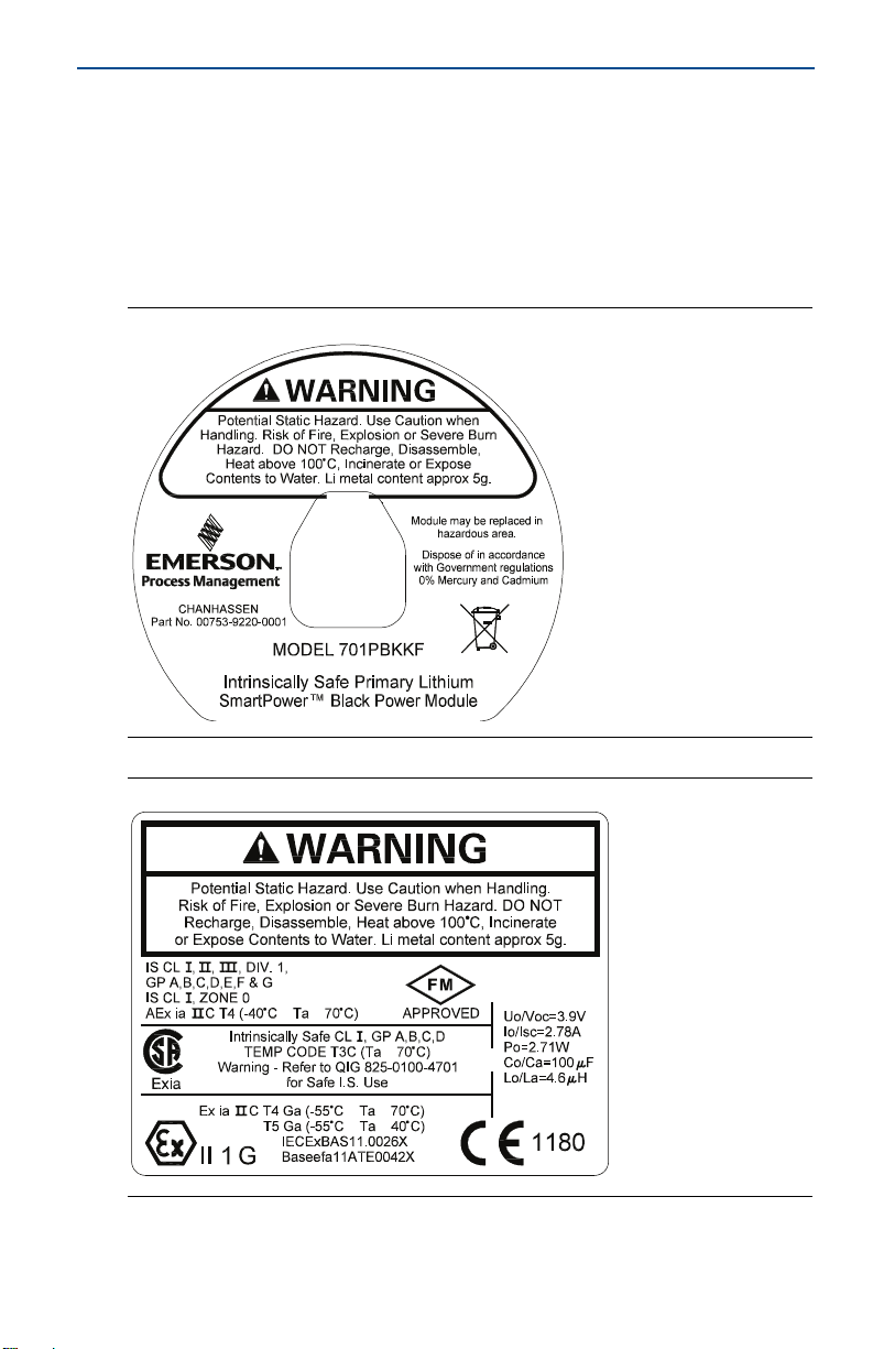
1.0 Warning on product labels
The Rosemount 701P power modules each have a warning printed on them. In
each case the warning text is the same. Below is a figure that shows each label.
The text of the warning is: “WARNING Potential Static Hazard, Use Caution when
Handling. Risk of Fire, Explosion or Severe Burn Hazard. DO NOT Recharge,
Disassemble, Heat above 100 °C, Incinerate or Expose Contents to Water. Li metal
content approx 5g.”
Figure 1. Warning Label on 701PBK
Figure 2. Warning Label on 701PGN
3
Quick Start Guide
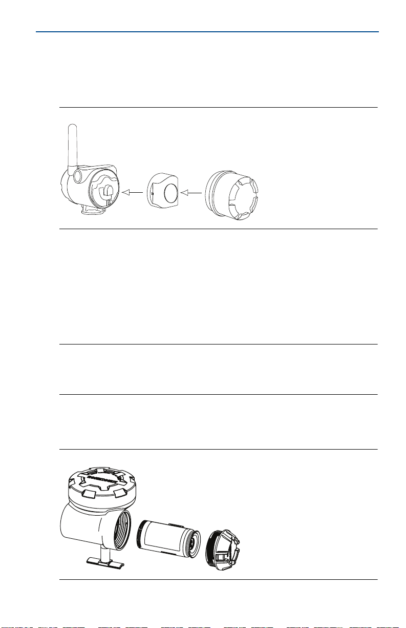
2.0 Physical installation
There are two types of power modules that will be discussed in this document.
They are the black power module (701PBK) and the green power module
(701PGN).
Figure 3. Black Power Module Installation
2.1 Black power module (701PBK)
1. Install the HART® device according to standard installation practices and the
manufacturer’s instructions, being sure to use an approved thread sealant on
all connections.
2. Unscrew the power module cover from the wireless device.
3. Connect the power module to the wireless device. The power module has a
keyed connection to prevent improper connection.
June 2016
Note
Wireless devices should be powered up in order of proximity from the Smart Wireless
Gateway, beginning with the closest device to the Gateway. This will result in a simpler and
faster network installation.
4. Close the housing cover and tighten. Always ensure a proper seal by installing
the electronics housing covers so that metal touches metal, but do not over
tighten.
Figure 4. Green Power Module Installation
4
June 2016
COMM
P/N 00753-9200-0020
1
2
3
4
Quick Start Guide
2.2 Green power module (701PGN)
1. Install the HART device according to standard installation practices and the
manufacturer’s instructions, being sure to use an approved thread sealant on
all connections.
2. Unscrew the power module cover from the wireless device.
3. Connect the green power module to the wireless device. The green power
module has a keyed connection to prevent improper connection. If the Green
power module is placed into the housing the wrong way, it will not fit entirely
into the housing.
Note
Wireless devices should be powered up in order of proximity from the Smart Wireless
Gateway, beginning with the closest device to the Gateway. This will result in a simpler and
faster network installation.
4. Close the housing cover and tighten. Ensure the power module cover is fully
tightened to prevent moisture ingress. The lip of the polymer power module
cover should be in contact with the surface of the polymer enclosure to ensure
a proper seal. Do not over tighten.
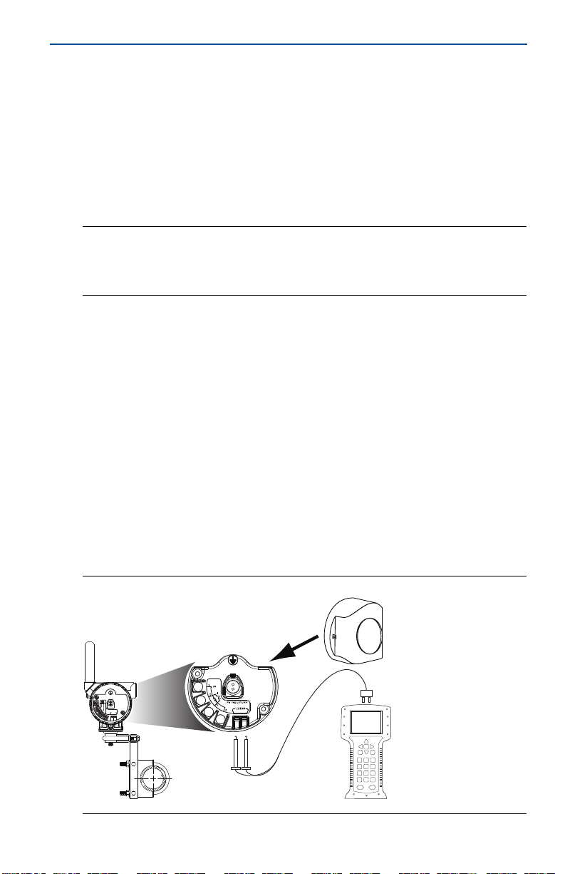
3.0 Verify operation
Operation can be verified in four locations: by using the Field Communicator, at
the Gateway via the Smart Wireless Gateway’s integrated web server, via AMS™
Wireless Configurator, or with the wireless device’s LCD display.
3.1 Field Communicator
If you are able to communicate to the wireless device via a Field Communicator,
the power module is powering the device and working correctly. Figure 5 shows
how to connect a Field Communicator to a wireless device with either the black or
green power module.
Figure 5. Field Communicator Connections
5
 Loading...