

Page 1
Rosemount Ultrasonic
3107 Level and 3108 Flow Transmitters
Reference Manual
00809-0200-4840, Rev BA
December 2014
Page 2

Page 3
Reference Manual
00809-0200-4840, Rev BA
Rosemount Ultrasonic
3107 and 3108 Transmitters
Title Page
December 2014
Read this manual before working with the product. For personal and system safety, and for
optimum product performance, make sure you thoroughly understand the contents before
installing, using, or maintaining this product.
Within the United States, Rosemount Inc. has two toll-free assistance numbers.
Customer Central: 1-800-999-9307 (7:00 a.m. to 7:00 p.m. CST)
Technical support, quoting, and order-related questions.
North American Response Center:
Equipment service needs.
1-800-654-7768 (24 hours a day – Includes Canada)
For equipment service or support needs outside the United States, contact your local
Rosemount representative.
The products described in this document are NOT designed for nuclear-qualified
applications.
Using non-nuclear qualified products in applications that require nuclear-qualified
hardware or products may cause inaccurate readings.
For information on Rosemount nuclear-qualified products, contact your local Rosemount
Sales Representative.
This device complies with part 15 of the FCC rules. Operation is subject to the following two
conditions: (1) This device may not cause harmful interference, and (2) this device must
accept any interference received, including interference that may cause undesired
operation.
Page 4

Title Page
December 2014
Reference Manual
00809-0200-4840, Rev BA
Page 5

Reference Manual
00809-0200-4840, Rev BA
Table of Contents
1Section 1: Introduction
1.1 Safety messages. . . . . . . . . . . . . . . . . . . . . . . . . . . . . . . . . . . . . . . . . . . . . . . . . . . . . . . .1
1.2 Manual overview . . . . . . . . . . . . . . . . . . . . . . . . . . . . . . . . . . . . . . . . . . . . . . . . . . . . . . .2
1.3 Service support. . . . . . . . . . . . . . . . . . . . . . . . . . . . . . . . . . . . . . . . . . . . . . . . . . . . . . . . .2
1.4 Product recycling/disposal . . . . . . . . . . . . . . . . . . . . . . . . . . . . . . . . . . . . . . . . . . . . . . .2
2Section 2: Transmitter Overview
2.1 Introduction to the transmitters . . . . . . . . . . . . . . . . . . . . . . . . . . . . . . . . . . . . . . . . . .3
2.2 Theory of operation . . . . . . . . . . . . . . . . . . . . . . . . . . . . . . . . . . . . . . . . . . . . . . . . . . . . .4
2.3 Components of the transmitter . . . . . . . . . . . . . . . . . . . . . . . . . . . . . . . . . . . . . . . . . .4
2.4 System architecture. . . . . . . . . . . . . . . . . . . . . . . . . . . . . . . . . . . . . . . . . . . . . . . . . . . . .5
Table of Contents
December 2014
3Section 3: Installation
3.1 Safety messages. . . . . . . . . . . . . . . . . . . . . . . . . . . . . . . . . . . . . . . . . . . . . . . . . . . . . . . .7
3.2 Considerations before installation . . . . . . . . . . . . . . . . . . . . . . . . . . . . . . . . . . . . . . . .8
3.2.1 Safety considerations . . . . . . . . . . . . . . . . . . . . . . . . . . . . . . . . . . . . . . . . . . . . 8
3.2.2 Environmental considerations. . . . . . . . . . . . . . . . . . . . . . . . . . . . . . . . . . . . . 9
3.3 Mechanical installation . . . . . . . . . . . . . . . . . . . . . . . . . . . . . . . . . . . . . . . . . . . . . . . . . .9
3.3.1 Consider liquid surface conditions . . . . . . . . . . . . . . . . . . . . . . . . . . . . . . . .11
3.3.2 Consider in-tank effects . . . . . . . . . . . . . . . . . . . . . . . . . . . . . . . . . . . . . . . . .11
3.3.3 Mounting the transmitter above the liquid surface. . . . . . . . . . . . . . . . . .11
3.3.4 Open channel flow installations . . . . . . . . . . . . . . . . . . . . . . . . . . . . . . . . . .12
3.4 Electrical installation . . . . . . . . . . . . . . . . . . . . . . . . . . . . . . . . . . . . . . . . . . . . . . . . . . 16
3.4.1 Connecting the transmitter . . . . . . . . . . . . . . . . . . . . . . . . . . . . . . . . . . . . . .16
3.4.2 Remote temperature sensor (on 3108 only) . . . . . . . . . . . . . . . . . . . . . . .17
3.4.3 Wiring to allow HART communication. . . . . . . . . . . . . . . . . . . . . . . . . . . . .18
3.4.4 Lightning / surge protection and other loop devices . . . . . . . . . . . . . . . .18
4Section 4: Configuration
Tab le of C ontents
4.1 Overview . . . . . . . . . . . . . . . . . . . . . . . . . . . . . . . . . . . . . . . . . . . . . . . . . . . . . . . . . . . . 19
4.2 Command parameters . . . . . . . . . . . . . . . . . . . . . . . . . . . . . . . . . . . . . . . . . . . . . . . . 20
4.2.1 Base units . . . . . . . . . . . . . . . . . . . . . . . . . . . . . . . . . . . . . . . . . . . . . . . . . . . . .20
4.2.2 Set as empty . . . . . . . . . . . . . . . . . . . . . . . . . . . . . . . . . . . . . . . . . . . . . . . . . . .21
4.2.3 Present depth . . . . . . . . . . . . . . . . . . . . . . . . . . . . . . . . . . . . . . . . . . . . . . . . . .22
TOC-i
Page 6

Table of Contents
December 2014
Reference Manual
00809-0200-4840, Rev BA
4.2.4 Learn false echo . . . . . . . . . . . . . . . . . . . . . . . . . . . . . . . . . . . . . . . . . . . . . . . .23
4.2.5 Auto tank map . . . . . . . . . . . . . . . . . . . . . . . . . . . . . . . . . . . . . . . . . . . . . . . . .24
4.2.6 Simulation of PV. . . . . . . . . . . . . . . . . . . . . . . . . . . . . . . . . . . . . . . . . . . . . . . .25
4.2.7 Restart device. . . . . . . . . . . . . . . . . . . . . . . . . . . . . . . . . . . . . . . . . . . . . . . . . .27
4.2.8 Load defaults . . . . . . . . . . . . . . . . . . . . . . . . . . . . . . . . . . . . . . . . . . . . . . . . . .28
4.2.9 Simulate current output. . . . . . . . . . . . . . . . . . . . . . . . . . . . . . . . . . . . . . . . .29
4.2.10 Trim 4mA / Trim 20mA . . . . . . . . . . . . . . . . . . . . . . . . . . . . . . . . . . . . . . . . . .30
4.3 Configuration parameters . . . . . . . . . . . . . . . . . . . . . . . . . . . . . . . . . . . . . . . . . . . . . 31
4.3.1 Message (P000) . . . . . . . . . . . . . . . . . . . . . . . . . . . . . . . . . . . . . . . . . . . . . . . .31
4.3.2 Tag (P001). . . . . . . . . . . . . . . . . . . . . . . . . . . . . . . . . . . . . . . . . . . . . . . . . . . . .32
4.3.3 Descriptor (P002). . . . . . . . . . . . . . . . . . . . . . . . . . . . . . . . . . . . . . . . . . . . . . .33
4.3.4 Final assembly number (P004) . . . . . . . . . . . . . . . . . . . . . . . . . . . . . . . . . . .34
4.3.5 Serial number (P005) . . . . . . . . . . . . . . . . . . . . . . . . . . . . . . . . . . . . . . . . . . .35
4.3.6 Bottom reference (P010) . . . . . . . . . . . . . . . . . . . . . . . . . . . . . . . . . . . . . . . .35
4.3.7 Upper blanking (P023) . . . . . . . . . . . . . . . . . . . . . . . . . . . . . . . . . . . . . . . . . .38
4.3.8 Lower blanking (P063) . . . . . . . . . . . . . . . . . . . . . . . . . . . . . . . . . . . . . . . . . .39
4.3.9 Distance offset (P060). . . . . . . . . . . . . . . . . . . . . . . . . . . . . . . . . . . . . . . . . . .40
4.3.10 Level offset (P069). . . . . . . . . . . . . . . . . . . . . . . . . . . . . . . . . . . . . . . . . . . . . .41
4.3.11 Tank shape / non-linear profile (P011). . . . . . . . . . . . . . . . . . . . . . . . . . . . .42
4.3.12 Contents (volume) measurement . . . . . . . . . . . . . . . . . . . . . . . . . . . . . . . .43
4.3.13 Flow measurement . . . . . . . . . . . . . . . . . . . . . . . . . . . . . . . . . . . . . . . . . . . . .48
4.3.14 Primary variable units (P012). . . . . . . . . . . . . . . . . . . . . . . . . . . . . . . . . . . . .51
4.3.15 Scale factor / K-factor (P013). . . . . . . . . . . . . . . . . . . . . . . . . . . . . . . . . . . . .52
4.3.16 Profile height / Power factor (P014) . . . . . . . . . . . . . . . . . . . . . . . . . . . . . . .53
4.3.17 Profile points 1 to 10 (P030 to P039) . . . . . . . . . . . . . . . . . . . . . . . . . . . . . .55
4.3.18 Upper range value (P015). . . . . . . . . . . . . . . . . . . . . . . . . . . . . . . . . . . . . . . .56
4.3.19 Lower Range Value (P016) . . . . . . . . . . . . . . . . . . . . . . . . . . . . . . . . . . . . . . .57
4.3.20 Damping (P020). . . . . . . . . . . . . . . . . . . . . . . . . . . . . . . . . . . . . . . . . . . . . . . .58
4.3.21 Lost echo delay (P021) . . . . . . . . . . . . . . . . . . . . . . . . . . . . . . . . . . . . . . . . . .59
4.3.22 Lost echo action (P022) . . . . . . . . . . . . . . . . . . . . . . . . . . . . . . . . . . . . . . . . .60
4.3.23 Speed of sound (P024) . . . . . . . . . . . . . . . . . . . . . . . . . . . . . . . . . . . . . . . . . .62
4.3.24 Temperature (P025) . . . . . . . . . . . . . . . . . . . . . . . . . . . . . . . . . . . . . . . . . . . .63
4.3.25 Set threshold (P026) . . . . . . . . . . . . . . . . . . . . . . . . . . . . . . . . . . . . . . . . . . . .64
4.3.26 Transmit power control (P040) . . . . . . . . . . . . . . . . . . . . . . . . . . . . . . . . . . .66
TOC-ii
4.3.27 Pulse repeat (P041) . . . . . . . . . . . . . . . . . . . . . . . . . . . . . . . . . . . . . . . . . . . . .67
4.3.28 Echoes needed (P042) . . . . . . . . . . . . . . . . . . . . . . . . . . . . . . . . . . . . . . . . . .67
4.3.29 Threshold 1 time (P043). . . . . . . . . . . . . . . . . . . . . . . . . . . . . . . . . . . . . . . . .68
Table of Contents
Page 7

Reference Manual
00809-0200-4840, Rev BA
5Section 5: Service and Troubleshooting
Table of Contents
December 2014
4.3.30 Threshold 1 size (P048). . . . . . . . . . . . . . . . . . . . . . . . . . . . . . . . . . . . . . . . . .69
4.3.31 Target pulses (P044) . . . . . . . . . . . . . . . . . . . . . . . . . . . . . . . . . . . . . . . . . . . .71
4.3.32 Target frequency (P045). . . . . . . . . . . . . . . . . . . . . . . . . . . . . . . . . . . . . . . . .72
4.3.33 Spike rejection (P049). . . . . . . . . . . . . . . . . . . . . . . . . . . . . . . . . . . . . . . . . . .73
4.3.34 False echo data (P081 to P088). . . . . . . . . . . . . . . . . . . . . . . . . . . . . . . . . . .74
4.3.35 Clear false echoes (P089) . . . . . . . . . . . . . . . . . . . . . . . . . . . . . . . . . . . . . . . .75
4.3.36 Transducer material (P970) . . . . . . . . . . . . . . . . . . . . . . . . . . . . . . . . . . . . . .76
4.3.37 Poll address (D951) . . . . . . . . . . . . . . . . . . . . . . . . . . . . . . . . . . . . . . . . . . . . .77
4.3.38 Maximum temperature (P046) . . . . . . . . . . . . . . . . . . . . . . . . . . . . . . . . . . .78
4.3.39 Minimum temperature (P047) . . . . . . . . . . . . . . . . . . . . . . . . . . . . . . . . . . .78
4.3.40 Date (P003). . . . . . . . . . . . . . . . . . . . . . . . . . . . . . . . . . . . . . . . . . . . . . . . . . . .79
5.1 Safety messages. . . . . . . . . . . . . . . . . . . . . . . . . . . . . . . . . . . . . . . . . . . . . . . . . . . . . . 81
5.2 Servicing . . . . . . . . . . . . . . . . . . . . . . . . . . . . . . . . . . . . . . . . . . . . . . . . . . . . . . . . . . . . 82
5.3 Power failure . . . . . . . . . . . . . . . . . . . . . . . . . . . . . . . . . . . . . . . . . . . . . . . . . . . . . . . . . 82
5.4 False echoes under certain ambient operating conditions. . . . . . . . . . . . . . . . . . 82
5.5 Monitoring and diagnostic parameters . . . . . . . . . . . . . . . . . . . . . . . . . . . . . . . . . . 83
5.5.1 Process Value / Primary Variable (PV) (D900). . . . . . . . . . . . . . . . . . . . . . .84
5.5.2 Level / Secondary Variable (SV) (D901) . . . . . . . . . . . . . . . . . . . . . . . . . . . .85
5.5.3 Distance / Tertiary Variable (TV) (D902) . . . . . . . . . . . . . . . . . . . . . . . . . . .86
5.5.4 Temperature / Fourth Variable (FV) (D903) . . . . . . . . . . . . . . . . . . . . . . . .87
5.5.5 % of current output (D905) . . . . . . . . . . . . . . . . . . . . . . . . . . . . . . . . . . . . . .88
5.5.6 Current output (D906) . . . . . . . . . . . . . . . . . . . . . . . . . . . . . . . . . . . . . . . . . .89
5.5.7 Distance (D910) . . . . . . . . . . . . . . . . . . . . . . . . . . . . . . . . . . . . . . . . . . . . . . . .90
5.5.8 Echo size (D911). . . . . . . . . . . . . . . . . . . . . . . . . . . . . . . . . . . . . . . . . . . . . . . .91
5.5.9 Echo success (D912) . . . . . . . . . . . . . . . . . . . . . . . . . . . . . . . . . . . . . . . . . . . .92
5.5.10 Target echoes (D913) . . . . . . . . . . . . . . . . . . . . . . . . . . . . . . . . . . . . . . . . . . .93
5.5.11 Speed of sound (D914) . . . . . . . . . . . . . . . . . . . . . . . . . . . . . . . . . . . . . . . . . .94
5.5.12 Temperature for SoS calculation (D915). . . . . . . . . . . . . . . . . . . . . . . . . . .94
5.5.13 Frequency (D916) . . . . . . . . . . . . . . . . . . . . . . . . . . . . . . . . . . . . . . . . . . . . . .96
5.5.14 Threshold in use (D917) . . . . . . . . . . . . . . . . . . . . . . . . . . . . . . . . . . . . . . . . .97
5.5.15 Pulses in use (D918) . . . . . . . . . . . . . . . . . . . . . . . . . . . . . . . . . . . . . . . . . . . .98
5.5.16 Transmit power (D919) . . . . . . . . . . . . . . . . . . . . . . . . . . . . . . . . . . . . . . . . .99
Tab le of C ontents
5.5.17 Model code (D949) . . . . . . . . . . . . . . . . . . . . . . . . . . . . . . . . . . . . . . . . . . . 100
5.5.18 Hardware rev. (D952) . . . . . . . . . . . . . . . . . . . . . . . . . . . . . . . . . . . . . . . . . 101
5.5.19 Software revision (D953) . . . . . . . . . . . . . . . . . . . . . . . . . . . . . . . . . . . . . . 102
TOC-iii
Page 8

Table of Contents
December 2014
Reference Manual
00809-0200-4840, Rev BA
5.5.20 Manufacturer (D960) . . . . . . . . . . . . . . . . . . . . . . . . . . . . . . . . . . . . . . . . . 103
5.5.21 Unique Device ID (D961) . . . . . . . . . . . . . . . . . . . . . . . . . . . . . . . . . . . . . . 104
5.5.22 HART revision (D962) . . . . . . . . . . . . . . . . . . . . . . . . . . . . . . . . . . . . . . . . . 105
5.5.23 Transmitter specific command rev. (D963) . . . . . . . . . . . . . . . . . . . . . . 106
5.5.24 Preambles (D964) . . . . . . . . . . . . . . . . . . . . . . . . . . . . . . . . . . . . . . . . . . . . 107
5.5.25 Transmitter flags (D965) . . . . . . . . . . . . . . . . . . . . . . . . . . . . . . . . . . . . . . 108
5.5.26 Primary variable trend. . . . . . . . . . . . . . . . . . . . . . . . . . . . . . . . . . . . . . . . . 108
5.5.27 Temperature trend . . . . . . . . . . . . . . . . . . . . . . . . . . . . . . . . . . . . . . . . . . . 109
5.5.28 Distance and echo size trend . . . . . . . . . . . . . . . . . . . . . . . . . . . .. . . . . . . 109
AAppendix A: Reference Data
A.1 Specifications . . . . . . . . . . . . . . . . . . . . . . . . . . . . . . . . . . . . . . . . . . . . . . . . . . . . . . . 111
A.1.1 General . . . . . . . . . . . . . . . . . . . . . . . . . . . . . . . . . . . . . . . . . . . . . . . . . . . . . 111
A.1.2 Measuring performance . . . . . . . . . . . . . . . . . . . . . . . . . . . . . . . . . . . . . . . 111
A.1.3 Configuration . . . . . . . . . . . . . . . . . . . . . . . . . . . . . . . . . . . . . . . . . . . . . . . . 112
A.1.4 Electrical . . . . . . . . . . . . . . . . . . . . . . . . . . . . . . . . . . . . . . . . . . . . . . . . . . . . 112
A.1.5 Materials of construction . . . . . . . . . . . . . . . . . . . . . . . . . . . . . . . . . . . . . . 113
A.1.6 Mechanical . . . . . . . . . . . . . . . . . . . . . . . . . . . . . . . . . . . . . . . . . . . . . . . . . . 113
A.1.7 Measuring . . . . . . . . . . . . . . . . . . . . . . . . . . . . . . . . . . . . . . . . . . . . . . . . . . . 113
A.1.8 Environment . . . . . . . . . . . . . . . . . . . . . . . . . . . . . . . . . . . . . . . . . . . . . . . . . 113
A.1.9 Temperature and pressure ratings . . . . . . . . . . . . . . . . . . . . . . . . . . . . . . 114
A.1.10 Load limitations . . . . . . . . . . . . . . . . . . . . . . . . . . . . . . . . . . . . . . . . . . . . . . 114
A.2 Dimensional drawings. . . . . . . . . . . . . . . . . . . . . . . . . . . . . . . . . . . . . . . . . . . . . . . . 115
A.3 Ordering information . . . . . . . . . . . . . . . . . . . . . . . . . . . . . . . . . . . . . . . . . . . . . . . . 118
A.3.1 Spare parts and accessories . . . . . . . . . . . . . . . . . . . . . . . . . . . . . . . . . . . . 120
BAppendix B: Product Certifications
B.1 Safety messages. . . . . . . . . . . . . . . . . . . . . . . . . . . . . . . . . . . . . . . . . . . . . . . . . . . . . 121
B.2 Approved manufacturing locations . . . . . . . . . . . . . . . . . . . . . . . . . . . . . . . . . . . . 122
B.3 European Union directive information. . . . . . . . . . . . . . . . . . . . . . . . . . . . . . . . . . 122
B.4 MCERTS certification . . . . . . . . . . . . . . . . . . . . . . . . . . . . . . . . . . . . . . . . . . . . . . . . . 122
B.5 Hazardous locations certifications . . . . . . . . . . . . . . . . . . . . . . . . . . . . . . . . . . . . . 122
B.5.1 American and canadian approvals . . . . . . . . . . . . . . . . . . . . . . . . . . . . . . 122
B.5.2 European certifications. . . . . . . . . . . . . . . . . . . . . . . . . . . . . . . . . . . . . . . . 123
B.5.3 Rest of the world certifications . . . . . . . . . . . . . . . . . . . . . . . . . . . . . . . . . 123
B.6 Approval drawings . . . . . . . . . . . . . . . . . . . . . . . . . . . . . . . . . . . . . . . . . . . . . . . . . . . 125
TOC-iv
Table of Contents
Page 9

Reference Manual
00809-0200-4840, Rev BA
CAppendix C: Rosemount 3490 Series Universal Control Unit
DAppendix D: Field Communicator
Table of Contents
December 2014
C.1 Menus and parameters . . . . . . . . . . . . . . . . . . . . . . . . . . . . . . . . . . . . . . . . . . . . . . . 127
D.1 Menus and parameters . . . . . . . . . . . . . . . . . . . . . . . . . . . . . . . . . . . . . . . . . . . . . . . 131
Tab le of C ontents
TOC-v
Page 10

Table of Contents
December 2014
Reference Manual
00809-0200-4840, Rev BA
TOC-vi
Table of Contents
Page 11

Reference Manual
00809-0200-4840, Rev BA
Section 1 Introduction
Safety messages . . . . . . . . . . . . . . . . . . . . . . . . . . . . . . . . . . . . . . . . . . . . . . . . . . . . . . . . . page 1
Manual overview . . . . . . . . . . . . . . . . . . . . . . . . . . . . . . . . . . . . . . . . . . . . . . . . . . . . . . . . page 2
Service support . . . . . . . . . . . . . . . . . . . . . . . . . . . . . . . . . . . . . . . . . . . . . . . . . . . . . . . . . . page 2
Product recycling/disposal . . . . . . . . . . . . . . . . . . . . . . . . . . . . . . . . . . . . . . . . . . . . . . . . page 2
1.1 Safety messages
Procedures and instructions in this manual may require special precautions to ensure the safety
of the personnel performing the operations. Information that raises potential safety issues is
indicated by a caution symbol ( ). The external hot surface symbol ( ) is used when a surface
is hot and care must be taken to avoid possible burns. If there is a risk of an electrical shock the
( ) symbol is used. Refer to the safety messages listed at the beginning of each section before
performing an operation preceded by this symbol.
Section 1: Introduction
December 2014
Failure to follow these installation guidelines could result in death or serious injury.
Make sure only qualified personnel perform the installation.
Use the equipment only as specified in this manual. Failure to do so may impair the
protection provided by the equipment.
Explosions could result in death or serious injury.
Verify that the operating environment of the transmitter is consistent with the
appropriate hazardous locations certifications.
Before connecting a HART
®
-based communicator in an explosive atmosphere, make
sure the instruments in the loop are installed in accordance with intrinsically safe or
non-incendive field wiring practices.
Electrical shock could cause death or serious injury.
Use extreme caution when making contact with the leads and terminals.
Any substitution of non-recognized parts may jeopardize safety. Repair, e.g. substitution of
components etc., may also jeopardize safety and is under no circumstances allowed.
1
Page 12

Section 1: Introduction
December 2014
1.2 Manual overview
This manual provides installation, configuration, and maintenance information for the
Rosemount 3107 Level and 3108 Flow Transmitter.
Section 2: Transmitter Overview
Section 3: Installation
Section 4: Configuration
Section 5: Service and Troubleshooting
Section A: Reference Data
Section B: Product Certifications
Section C: Rosemount 3490 Series Universal Control Unit
Section D: Field Communicator
1.3 Service support
Reference Manual
00809-0200-4840, Rev BA
To expedite the return process outside of the United States, contact the nearest Emerson
Process Management representative.
Within the United States, call the Emerson Process Management Instrument and Valves
Response Center using the 1 800 654 7768 toll-free number. This center, available 24 hours a
day, will assist you with any needed information or materials.
The center will ask for product model and serial numbers, and will provide a Return Material
Authorization (RMA) number. The center will also ask for the process material to which the
product was last exposed.
Individuals who handle products exposed to a hazardous substance can avoid injury if they
are informed of, and understand, the hazard. If the product being returned was exposed to
a hazardous substance as defined by OSHA, a copy of the required Material Safety Data
Sheet (MSDS) for each hazardous substance identified must be included with the returned
goods.
1.4 Product recycling/disposal
Recycling of equipment and packaging should be taken into consideration. The product and
packaging should be disposed of in accordance with local and national legislation.
2
Page 13
Reference Manual
B
E
E
20mA
4mA
F
D
D
C
A
G
00809-0200-4840, Rev BA
Section 2: Transmitter Overview
Section 2 Transmitter Overview
Introduction to the transmitters . . . . . . . . . . . . . . . . . . . . . . . . . . . . . . . . . . . . . . . . . . . page 3
Theory of operation . . . . . . . . . . . . . . . . . . . . . . . . . . . . . . . . . . . . . . . . . . . . . . . . . . . . . . page 4
Components of the transmitter . . . . . . . . . . . . . . . . . . . . . . . . . . . . . . . . . . . . . . . . . . . page 4
System architecture . . . . . . . . . . . . . . . . . . . . . . . . . . . . . . . . . . . . . . . . . . . . . . . . . . . . . . page 5
2.1 Introduction to the transmitters
The Rosemount 3107 and Rosemount 3108 are sealed 4–20 mA loop-powered liquid level
transmitters, and are designed for use in waste water and effluent treatment plant applications.
The 3108 is MCERTS certified for open flow channel applications.
These rugged UPVC transmitters are certified Intrinsically Safe for use in Zone 0 areas, and
factory fitted with up to 164 ft. (50 m) of two-core cable for simple low cost installation in
sumps, wet-wells and over open channel flow structures.
December 2014
The transmitters can be connected directly to a plant control system, or used with a Rosemount
3490 Series Control Unit for programmable control functionality.
Note
The Rosemount 3490 Series Control Unit software must be version 3.40 or later.
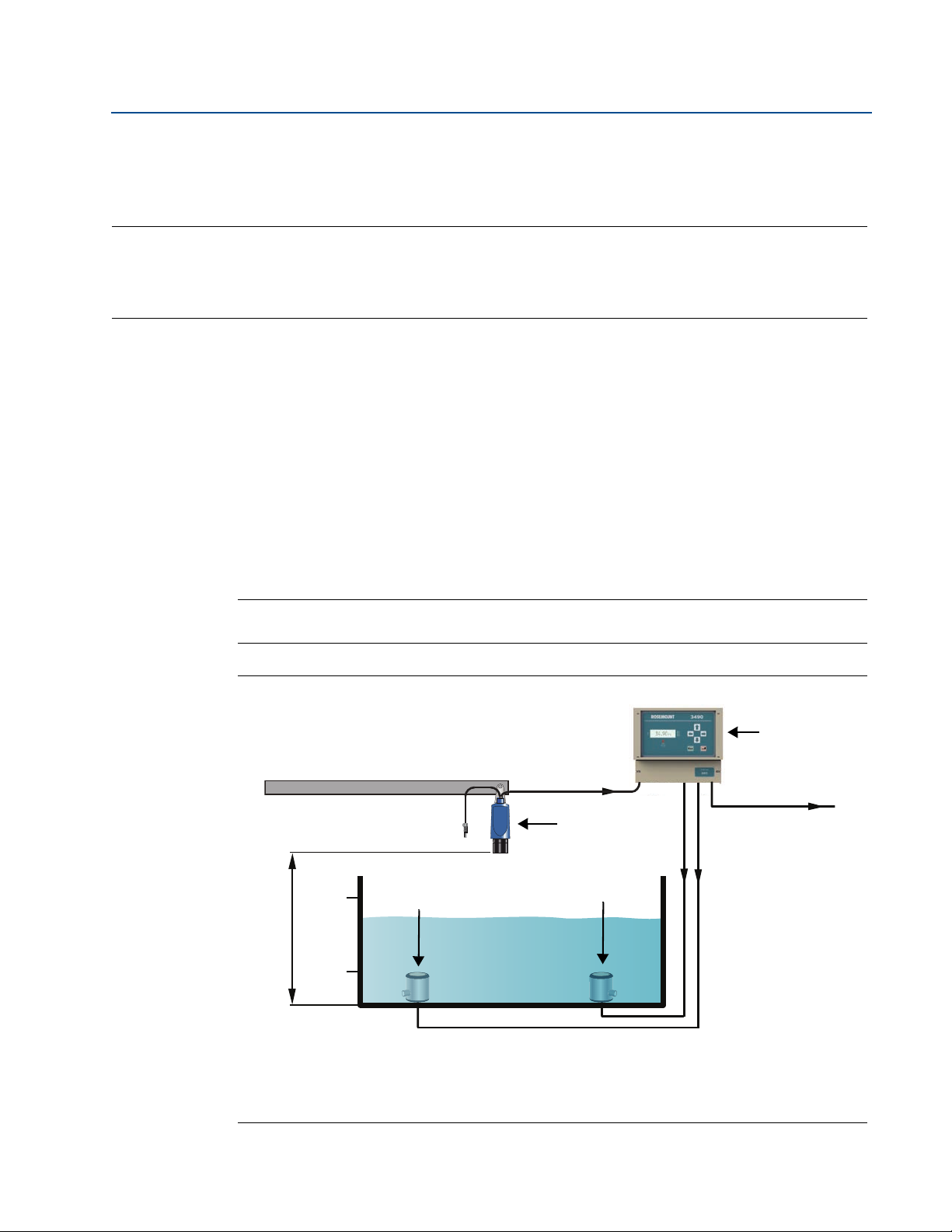
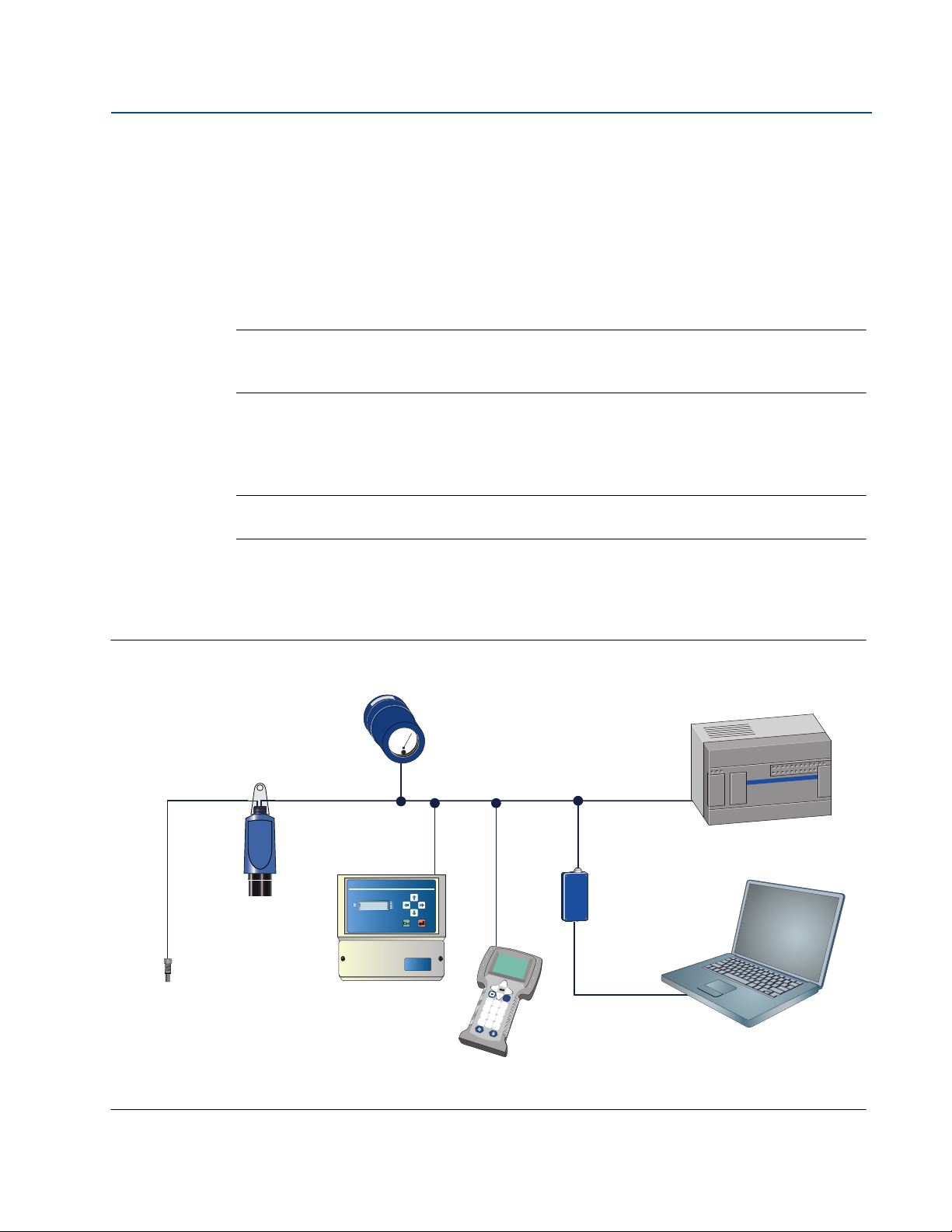
Figure 2-1. Typical application using a Rosemount 3108 flow transmitter
A. Rosemount 3108 Flow Transmitter E. Pump
B. Rosemount 3490 Series Control Unit F. Transmitter Bottom Reference
C. 4–20 mA signal output G. 4–20 mA and HART signal input
D. Relay
3
Page 14
Section 2: Transmitter Overview
D
C
E
B
A
D
December 2014
2.2 Theory of operation
The level transmitter is designed to be mounted above a liquid (Figure 2-1 on page 3), and uses
ultrasonic pulses to continuously measure the distance to the liquid surface. The electronics
calculate distance to the liquid level using the time delay between transmitting and receiving
signals.
When programmed with the bottom reference of the application – usually the bottom of a tank
– the transmitter calculates the liquid depth (level), and outputs the result as a 4–20 mA and
HART signal.
The 3108 and the 3107 can calculate contents (volume) or open channel flow when
programmed with further application information, and outputs the result as a 4–20 mA and
HART signal.
2.3 Components of the transmitter
Reference Manual
00809-0200-4840, Rev BA
The transmitter has a housing containing advanced electronics to generate ultrasonic pulses,
®
process the resultant signals, and provide a 4–20mA and HART
output.
There is a factory-fitted cable for the signal output and connecting an external power supply.
The 3108 has a factory-fitted Remote Temperature Sensor.
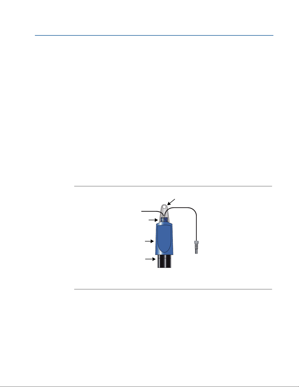
Figure 2-2. Transmitter components
A. Mounting bracket D. UPVC wetted parts
B. Two-core cable E. Remote temperature sensor (3108 only)
C. 1-in. mounting thread
4
Page 15
Reference Manual
751 Display
Rosemount 3490
Series Controller
Field
Communicator
HART
Modem
AMS
™
Suite:
Intelligent Device Manager
Control System
Remote Temperature Sensor
(Rosemount 3108 only)
Rosemount
3107/3108
Tra ns mit te r
4–20 mA / HART
00809-0200-4840, Rev BA
2.4 System architecture
The Rosemount 3107 and 3108 are loop-powered which means they use the same two wires for
both power supply and output signal.
The transmitter can be connected to any suitable direct current (dc) power source using the
factory-fitted two-core, shielded cable.
The output is a 4–20mA analog signal and a digital HART signal.
Note
It is possible to use the multidrop function with the HART protocol (see Figure 2-3). In
this case, communication is restricted to digital since the current is fixed to 4 mA.
The transmitters can easily be configured by using a Rosemount 3490 Series Control Unit.
Alternatively, a Field Communicator, or a PC with AMS
software, can be used to configure the transmitter.
Note
The Rosemount 3490 Control Unit software must be version 3.40 or later.
Section 2: Transmitter Overview
December 2014
™
Suite: Intelligence Device Manager
A comprehensive specification for the Rosemount 3107 and 3108 is in the section
“Specifications” on page 111.
Figure 2-3. System architecture
3490
Model type:
3491
Fn
1
2
3
4
5
6
7
8
9
.
0
-
5
Page 16

Section 2: Transmitter Overview
December 2014
Reference Manual
00809-0200-4840, Rev BA
6
Page 17

Reference Manual
00809-0200-4841, Rev BA
Section 3 Installation
Safety messages . . . . . . . . . . . . . . . . . . . . . . . . . . . . . . . . . . . . . . . . . . . . . . . . . . . . . . . . . page 7
Considerations before installation . . . . . . . . . . . . . . . . . . . . . . . . . . . . . . . . . . . . . . . . . page 8
Mechanical installation . . . . . . . . . . . . . . . . . . . . . . . . . . . . . . . . . . . . . . . . . . . . . . . . . . . page 9
Electrical installation . . . . . . . . . . . . . . . . . . . . . . . . . . . . . . . . . . . . . . . . . . . . . . . . . . . . . page 16
3.1 Safety messages
Procedures and instructions in this manual may require special precautions to ensure the safety
of the personnel performing the operations. Information that raises potential safety issues is
indicated by a caution symbol ( ). The external hot surface symbol ( ) is used when a surface
is hot and care must be taken to avoid possible burns. If there is a risk of an electrical shock the
( ) symbol is used. Refer to the safety messages listed at the beginning of each section before
performing an operation preceded by this symbol.
Section 3: Installation
December 2014
Failure to follow these installation guidelines could result in death or serious injury
Make sure only qualified personnel perform the installation.
Use the equipment only as specified in this manual. Failure to do so may impair the
protection provided by the equipment.
Explosions could result in death or serious injury
Verify that the operating environment of the transmitter is consistent with the
appropriate hazardous locations certifications.
Before connecting a HART
®
-based communicator in an explosive atmosphere, make
sure the instruments in the loop are installed in accordance with intrinsically safe or
non-incendive field wiring practices.
Electrical shock could cause death or serious injury
Use extreme caution when making contact with the leads and terminals.
Any substitution of non-recognized parts may jeopardize safety. Repair, e.g. substitution of
components etc., may also jeopardize safety and is under no circumstances allowed.
Section 3: Installation
7
Page 18

Section 3: Installation
December 2014
3.2 Considerations before installation
The Rosemount 3107 and 3108 may be used for level and volume measurement in open or
closed tanks, or open channel flow measurement.
The transmitter must be installed in a location where it is protected from ultraviolet radiation to
prevent long term degradation of the plastics used in its construction e.g. shrouded from direct
sunlight.
It is important to correctly position the transmitter for reliable ultrasonic level measurement.
For maximum accuracy and stability of the level measurement reading, the transmitter should
always be shrouded from direct sunlight and radiated heat.
The transmitter may be site-tuned to deal with most application conditions, but it is
recommended that the following guidelines be adopted wherever relevant.
3.2.1 Safety considerations
Guidelines
Reference Manual
00809-0200-4841, Rev BA
1. Installation must be carried out by suitably trained personnel in accordance with the
applicable code of practice.
2. If the equipment is likely to come into contact with aggressive substances, it is the
responsibility of the user to take suitable precautions that prevent it from being
adversely affected, thus ensuring that the type of protection is not compromised.
Aggressive substances are acidic liquids or gases that may attack metals or solvents
that may affect polymeric materials.
Suitable precautions are regular checks as part of routine inspections, or establishing,
from the material's datasheet, that it is resistant to specific chemicals.
3. The equipment should only be cleaned with a damp cloth. Do not use solvents.
4. The equipment is not intended to be repaired by the user and is to be replaced by an
equivalent certified unit. Repairs should only be carried out by the manufacturer or
approved repairer.
5. The transmitter is Double Insulated, and therefore Protective Earthing is not required.
6. Note that if the equipment is used in a manner not specified by the manufacturer, the
protection afforded by the equipment may be impaired.
7. To ensure electro-magnetic compatibility in any European member state, it should not
be installed in a residential area.
Note
It is not advisable to mount the transmitter in close proximity to a source of electrical
noise such as a variable-speed drive, or other high-powered electrical device.
Section 3: Installation8
Page 19
Reference Manual
OKOK OK
00809-0200-4841, Rev BA
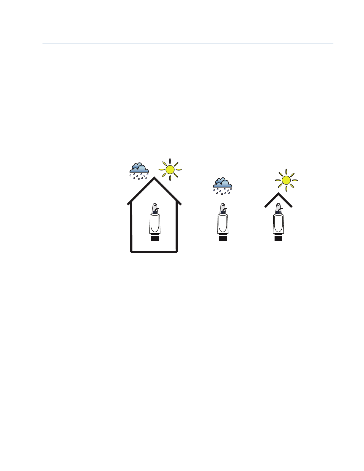
3.2.2 Environmental considerations
The Rosemount 3107 and 3108 ultrasonic transmitters are Intrinsically Safe (IS) approved for
hazardous area installations.
1. The 3107 is designed for open or closed tank installation. It is weatherproof and
protected against the ingress of dust
2. The 3108 is designed for open channel flow measurement. It is weatherproof and
protected against the ingress of dust
3. Avoid installing the 3107 and 3108 near heat sources
Figure 3-1. Environmental considerations
Section 3: Installation
December 2014
3.3 Mechanical installation
Guidelines
1. Mount the transmitter above the liquid using the 1-in. thread provided, but not closer
than 12 in. (0,3 m) to the surface. The transmitter does not detect any liquid surface
closer than 12 in. (0,3 m) to the transmitter face. (See “Mounting the transmitter above
the liquid surface” on page 11).
Optional flanges and bracket kits are available to help mounting.
(See “Spare parts and accessories” on page 120.)
2. The transmitter should be mounted vertically to ensure a good echo from the liquid
surface. The transmitter beam half angle is 6 degrees (See Figure 3-2 on page 10).
3. Obstructions in the tank, or well, may generate echoes which can be confused with the
real liquid surface echo. Obstructions within the beam angle generate strong false
echoes. Wherever possible, the transmitter should be positioned to avoid false echoes.
Section 3: Installation
9
Page 20

Section 3: Installation
A
C
B
December 2014
4. To avoid detecting unwanted objects in the tank or well, it is advisable to maintain a
5. No false echoes are generated if the transmitter is located near the side of the tank or
6. If the transmitter is mounted in an enclosed tank with a domed top, avoid mounting
7. Avoid applications where heavy condensation could form on the transmitter face.
8. If the transmitter is mounted in a stand-off or nozzle, the transmitter face should
9. If the transmitter is used in environments where direct sunlight can cause high surface
Reference Manual
00809-0200-4841, Rev BA
distance of at least 1.3 in. from the center line of the transmitter for every foot (11 cm
per meter) range to the obstruction.
well, and the wall is smooth and free of protrusions. However, there will still be a
reduction in the echo size. It is recommended that the transmitter be mounted no
closer than 12 in. (0,3 m) to the wall to avoid a large reduction in the echo size.
the transmitter in the center of the tank roof because this could act as a parabolic
reflector and create unwanted echoes.
protrude at least 0.2 in. (5 mm) into the tank.
temperatures on exposed instruments, a sun-shade is recommended.
Figure 3-2. Considerations when installing in a tank
A. Transmitter is mounted vertically (maximum deviation of 3°).
B. 6° beam half angle.
C. 1.3 in./ft. (11 cm/m). Minimum of 12 in. (0.3 m).
Section 3: Installation10
Page 21

Reference Manual
00809-0200-4841, Rev BA
3.3.1 Consider liquid surface conditions
Guidelines
1. Foaming liquids can reduce the size of the returned echo because foam is a poor
ultrasonic reflector.
Mount an ultrasonic transmitter over an area of clear liquid, such as near the inlet to a
tank or well. In extreme conditions, or where this is not possible, the transmitter may
be mounted in a vented stilling tube provided that the inside measurement of the
stilling tube is at least 4 in. (100 mm) and is smooth and free from joints or protrusions.
It is important that the bottom of the stilling tube stays covered to prevent the ingress
of foams.
2. Avoid mounting the transmitter directly over any inlet stream.
3. Liquid surface turbulence is not normally a problem unless it is excessive. The effects of
turbulence are minor, but excessive turbulence can be dealt with by fine-tuning the
transmitter on site, if necessary.
Section 3: Installation
December 2014
3.3.2 Consider in-tank effects
Guidelines
1. Stirrers or agitators can cause a vortex. Mount the transmitter off-center of any vortex
to maximize the return echo.
2. If stirrer blades become uncovered, they create echoes as they pass through the
ultrasonic beam. The transmitter can learn to ignore false echoes (see “Learn false
echo” on page 23).
3. In tanks with rounded or conical bottoms, mount the transmitter off-center. If needed,
a perforated reflector plate can be installed on the tank bottom directly under the
transmitter center line to ensure a satisfactory return echo.
4. Avoid detecting pump casings, as the liquid falls away, by not mounting the transmitter
directly above pumps. If this is not possible, fine-tuning of the transmitter on-site may
be required.
3.3.3 Mounting the transmitter above the liquid surface
A 1-in. thread is provided to mount the transmitter. The thread form is either BSPP (G1) or NPT,
and is marked below the mounting thread.
To help installation, flange accessories and bracket kits are available from Emerson Process
Management. The accessory flanges supplied are manufactured from PVC and are a full face
design. Care must be taken when installing to raised face mating flanges on the tank or vessel to
prevent distortion of the PVC flange by over-tightening the bolts. See “Spare parts and
accessories” on page 120 for ordering information.
Section 3: Installation
Note
Never suspend the transmitter by the cable.
11
Page 22

Section 3: Installation
December 2014
Bracket mounting
The transmitter is supplied with a purpose made 316 Stainless Steel mounting bracket which
should be used to mount the transmitter over the liquid surface. The bracket is designed to fit
over the threaded neck of the transmitter and is retained by a locknut (see “1-in. NPT/BSPP
bracket kits” on page 117 for dimensions).
Use a chain or wire through the hole provided in the bracket, which is shaped to ensure that the
transmitter will hang perpendicular to the liquid surface. Check that the material of the chain or
wire is corrosion resistant to the liquids and any vapors present.
The bracket may be bolted to a suitable cross member above the liquid surface. Ensure that the
transmitter is perpendicular to the liquid surface to maximise the return echo size.
Note
Check that the maximum liquid level will not enter the 12 in. (0.3 m) blanking zone of
To help with alignment, the echo size (signal strength) can be indicated on the
Reference Manual
00809-0200-4841, Rev BA
the transmitter.
Rosemount 3490 Series Control Unit or a Field Communicator.
Flange mounting
The instrument (accessory) flanges supplied by Emerson are manufactured from PVC and are a
full face design. Care must be taken when installing to a raised face mating flange on the tank or
vessel to prevent distortion of the PVC flange by over-tightening the bolts. See “Spare parts and
accessories” on page 120 for part numbers.
Mounting from a conduit
The 3107 and the 3108 can be mounted from a conduit using the optional adaptor
(03107-7003-0003 and 03107-7003-1004). See “Spare parts and accessories” on page 120.
3.3.4 Open channel flow installations
There are normally two distinct parts to an open channel flow measurement system; the
primary element (flow structure) and the secondary element (Head measurement instrumentation). For accurate open channel flow measurement, both parts of the system must be correctly
installed. This section explains the important parts of installing the transmitter (secondary
element). The flow structure (primary element) installation can be referenced in the British
(BS3680) or ISO International standards.
Note
The transmitter should be free from a situation where it is likely to 'drown' (refer to the
relevant standard for further information)
The Rosemount 3108 has a factory-fitted Remote Temperature Sensor.
See “Positioning of the remote temperature sensor (3108 only)” on page 14.
For some installations, the use of a calibration device is mandatory. Emerson offers the
Rosemount Head Verification Device (HVD) for this purpose. See “Spare parts and
accessories” on page 120 for further information.
Section 3: Installation12
Page 23
Reference Manual
A
B
C
D
A
C
B
00809-0200-4841, Rev BA
Positioning of the transmitter
The positioning is critical, and should be the correct distance upstream from the flow structure
as stated in the relevant standard for your country. For example, in the ISO standards, the
distance should be four to five times the maximum height of the water (Hmax) for a thin plate
weir, or three to four times Hmax for a flume. For optimum accuracy, position the transmitter’s
front face at a height equal to the sum of the maximum flow depth plus the transmitter
deadband of 12.2 in. (300 mm) plus an extra 2 in. (50 mm).
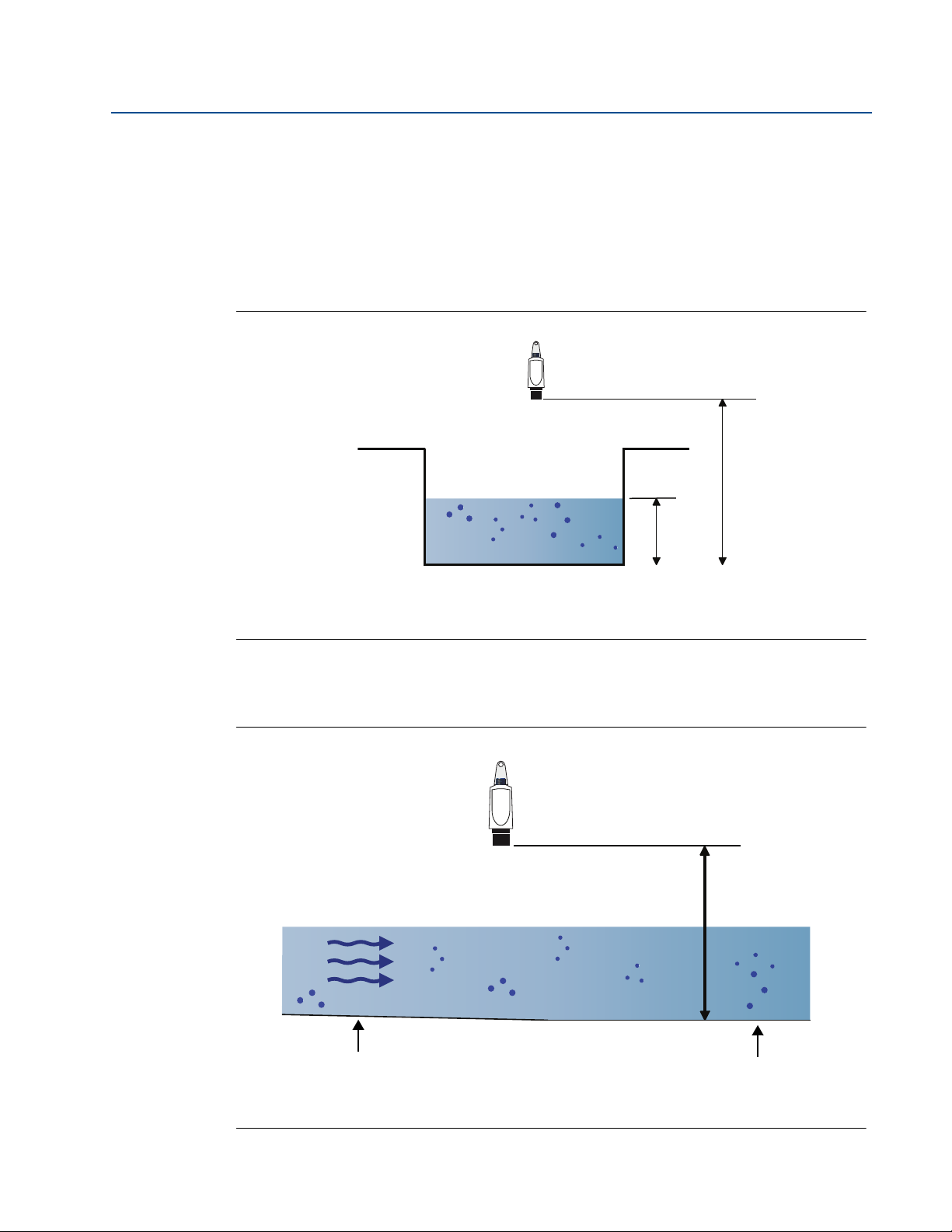
Figure 3-3. Choosing the height position above a flow
Section 3: Installation
December 2014
A. Transmitter front face
B. Hmax
C. Transmitter bottom reference = Hmax + 12.2 in. (300 mm) + 2 in. (50 mm)
It is important that the bottom reference of the transmitter should be related to the datum of
the primary measuring device (Figure 3-4).
Figure 3-4. Bottom Reference of a flume or weir
Section 3: Installation
A. Transmitter bottom reference C. Approach channel
B. Primary element (e.g. flume, weir) invert D. Flow
13
Page 24
Section 3: Installation
B
A
December 2014
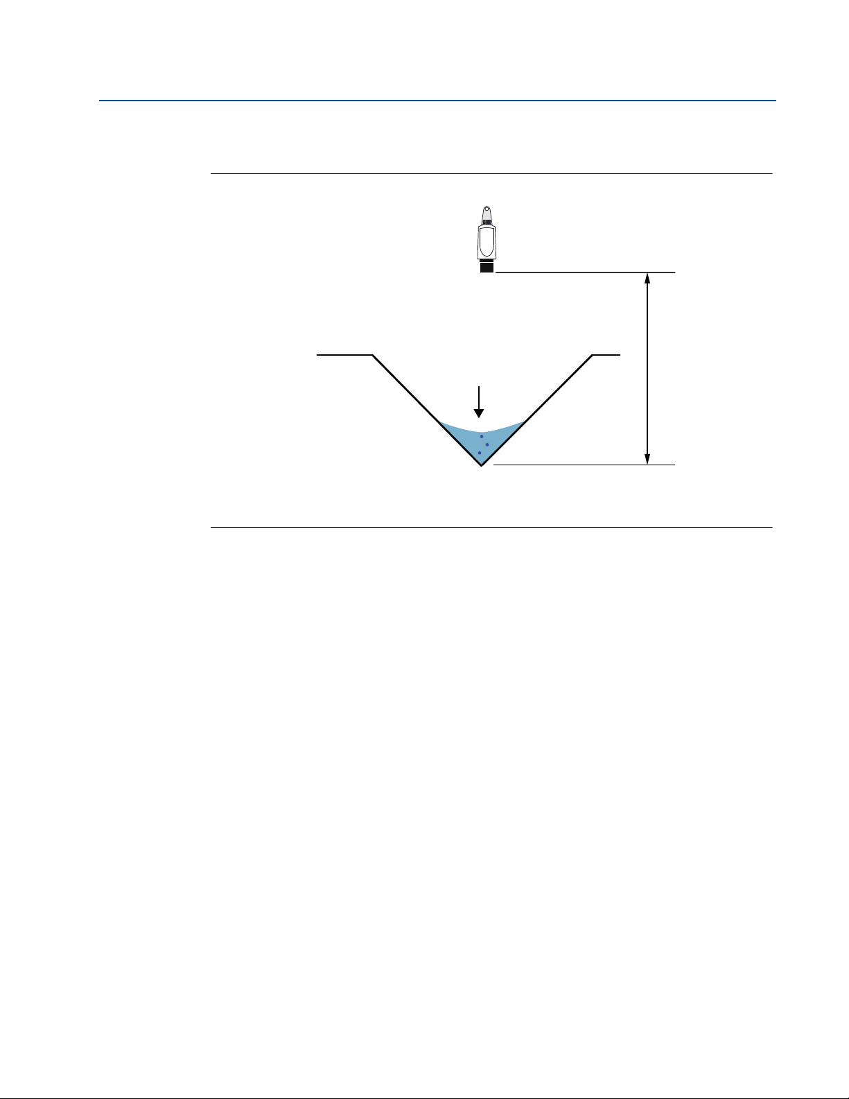
When setting the bottom reference on a ‘V’ notch weir, it is important the true invert is used and
not the meniscus level (Figure 3-5).
Figure 3-5. Bottom reference of a ‘V’ notch weir
Reference Manual
00809-0200-4841, Rev BA
A. Transmitter bottom reference (i.e. true invert)
B. Meniscus level
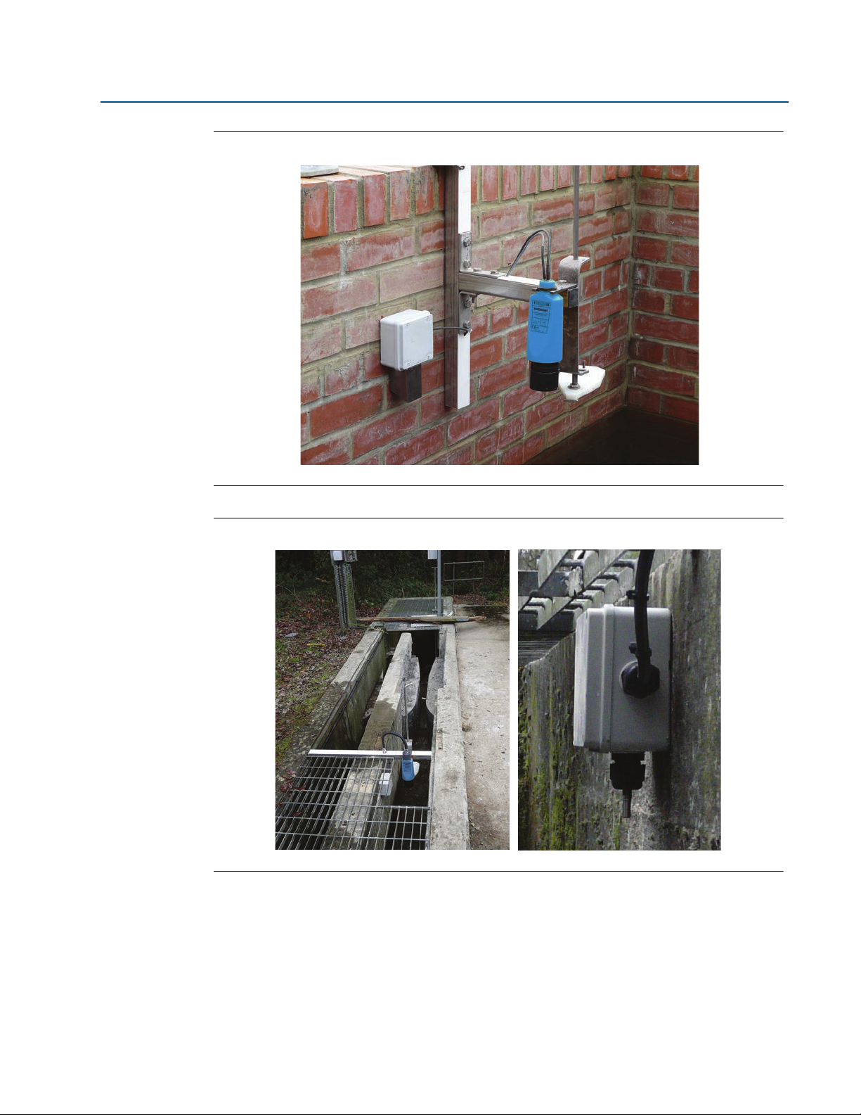
Positioning of the remote temperature sensor (3108 only)
The Rosemount 3108 transmitter has a factory fitted remote temperature sensor. The
temperature sensor is enclosed in a M8 x 1.5 threaded stainless steel body.
Figure 3-6 and Figure 3-7 on page 15 show two typical arrangements for installing the
temperature sensor in an open or enclosed chamber. The sensor may be installed in a suitable
plastic conduit box and clamped in place using a suitable compression type cable gland.
1. Open weir chamber (Figure 3-6 on page 15)
Mount the remote temperature sensor so that it is representative of the mean air
temperature in the chamber and is in a shaded area away from direct sunlight and solar
radiation.
2. Enclosed or partially covered flume chamber (Figure 3-7 on page 15)
Mount the remote temperature sensor in the approach channel, in a shaded area away
from direct sunlight and solar radiation. In Figure 3-7 on page 15, the sensor is partially
covered by grating which helps prevent solar gain. (Full grating is removed for clarity.)
The temperature sensor should be positioned in the weir chamber or flume approach channel so
the average air temperature can be accurately measured. The temperature sensor must be
protected at all times from direct sunlight and any radiated heat.
In extreme high temperatures, for the best accuracy and stability of level measurement reading,
the transmitter should be shrouded to prevent the incidence of direct sunlight and solar
radiation. If the flow structure permits, mount the transmitter within the flow channel or
chamber.
Section 3: Installation14
Page 25
Reference Manual
00809-0200-4841, Rev BA
Figure 3-6. Open weir chamber arrangement with Rosemount Head Verification Device
Section 3: Installation
December 2014
Figure 3-7. Enclosed or partially covered flume chamber arrangement
Section 3: Installation
15
Page 26

Section 3: Installation
December 2014
3.4 Electrical installation
3.4.1 Connecting the transmitter
The Rosemount 3490 Series is a two-wire loop-powered transmitter accepting power supplies
as follows:
12 to 40 Vdc in a non-hazardous area (ordinary location)
12 to 30 Vdc in a hazardous area (classified location)
Note
To comply with the CSA requirements, the transmitters must be powered from a
Rosemount 3490 Series Control Unit or class 2 or separate extra-low voltage (SELV)
source.
Other devices may reset if connecting the transmitter to a multi-drop system while the
loop is powered. De-energize the loop to avoid devices being reset.
Reference Manual
00809-0200-4841, Rev BA
Each transmitter is supplied with a factory-fitted PVC sheathed, two-core, shielded cable for
communications and external power supply connections. There are no cable conduit entries
and no covers to remove. The cable may be cut to length on site or may be extended using a
junction box and suitable extension cable.
See “Wiring to allow HART communication” on page 18 if HART digital communication is
required.
Installation in a non-hazardous area (ordinary location)
The 3107 and the 3108 are suitable for non-hazardous (ordinary location) applications.
To connect the transmitter:
1. Make sure that the power supply is disconnected.
2. Connect the cable wires as shown in Figure 3-8 on page 17, taking note of the required
voltage of 12 to 40 Vdc for non-hazardous (ordinary location) applications.
Installation in a hazardous area (classified location)
The 3107 and the 3108 are suitable for Intrinsically Safe (IS) applications. Appendix B: Product
Certifications has the safety approval information and control drawings.
When the transmitters are used with a Rosemount 3490 Series Control Unit, no additional
safety barriers are required as the control unit output is Intrinsically Safe.
If powering the transmitter from any other source, ensure a suitable Intrinsically Safe (IS) barrier
is fitted in the non-hazardous area. The barrier must be chosen such that its output parameters
Uo, Io and Po are less than Ui, Ii and Pi of the transmitter (see Appendix B: Product Certifications
for the parameter values). In addition, the sum of the capacitance and the inductance of the
transmitter and any extra cable fitted must not exceed the maximum specified for the barrier.
Suitable barriers include the MTL products 706, 706S, 787, and 787S.
Section 3: Installation16
Page 27

Reference Manual
A
C
B
D
00809-0200-4841, Rev BA
To connect the transmitter:
1. Make sure that the power supply is disconnected.
2. Connect the cable wires (see Figure 3-8 on page 17), taking note of the restricted
Note
Other devices may reset if connecting the transmitter to a multi-drop system while the
Make sure that the instruments in the loop are installed according to intrinsically-safe
Figure 3-8. Wiring diagram
Section 3: Installation
December 2014
voltage of 12 to 30 Vdc for hazardous area (classified location) applications.
loop is powered. De-energize loop to avoid devices being reset.
field wiring practices and control drawings, when applicable.
A. Black: 0 Vdc
B. Red: 12 to 40 Vdc (for non-hazardous area) or 12 to 30 Vdc from protective barrier (for hazardous area)
C. Non-hazardous area: connect cable screen to standard ground (earth) or
hazardous area: connect cable screen to intrinsically safe ground (earth)
D. Remote temperature sensor (3108 only)
3.4.2 Remote temperature sensor (on 3108 only)
The factory-fitted remote temperature sensor on the 3108 may be installed in a hazardous area
without the need for any additional protection or barriers.
Note
See also “Positioning of the remote temperature sensor (3108 only)” on page 14.
Section 3: Installation
17
Page 28

Section 3: Installation
December 2014
3.4.3 Wiring to allow HART communication
If HART communications is required, a 250 Ohm (minimum), 0.25 W load resistor must be
installed in the loop. (See “Load limitations” on page 114).
Note
When the transmitter is used with a Rosemount 3490 Series Control Unit, there is no
need to install an external load resistor in the loop because a suitable resistor is built in
to the control unit.
If the transmitter is being supplied through a safety barrier, ensure the type chosen will pass
HART information.
After the load resistor is installed, a Field Communicator can be connected across the load
resistor, or across the loop at any point downstream of the load resistor. It is the responsibility
of the installer to ensure that any Field Communicator used in the hazardous area is
suitably certified.
Note
Make sure that the instruments in the loop are installed according to intrinsically-safe
field wiring practices and control drawings, when applicable.
Reference Manual
00809-0200-4841, Rev BA
3.4.4 Lightning / surge protection and other loop devices
If the area is prone to lightning strikes or voltage surges, a suppressor device may be installed
between the transmitter and the control unit.
If an additional loop-powered device or separately powered device is included in the two-wire
loop, ensure the transmitter receives a minimum voltage of 12 Vdc (see “Load limitations” on
page 114).
Section 3: Installation18
Page 29

Reference Manual
00809-0200-4840, Rev BA
Section 4 Configuration
Overview . . . . . . . . . . . . . . . . . . . . . . . . . . . . . . . . . . . . . . . . . . . . . . . . . . . . . . . . . . . . . . .page 19
Command parameters . . . . . . . . . . . . . . . . . . . . . . . . . . . . . . . . . . . . . . . . . . . . . . . . . . .page 20
Configuration parameters . . . . . . . . . . . . . . . . . . . . . . . . . . . . . . . . . . . . . . . . . . . . . . . page 31
4.1 Overview
The Rosemount 3107 and Rosemount 3108 support HART communications, which may be used
to program or interrogate the transmitters from any point on the two-wire loop.
This section contains information on configuring the transmitters using a
Field Communicator, PC with AMS, or Rosemount 3490 Series Control Unit.
Rosemount 3490 Series control unit
Section 4: Configuration
December 2014
The product manual 00809-0100-4841 provides detailed instructions on installation and
operation of the control unit.
A full menu map showing how to access transmitter parameters using the control unit’s menu
system is in Appendix Appendix C: Rosemount 3490 Series Universal Control Unit.
For convenience, the parameter identification numbers (P*** and D***) are used in parameter
headings and descriptions in this configuration section.
When using the control unit, use the Enter ( ) key to start editing a configuration parameter
and then use the arrow keys to change the setting. Changes are confirmed by pressing the Enter
key, or abandoned by pressing the Esc key. Commands e.g. Set As Empty are run using the
Enter () key.
Note
The Rosemount 3490 Control Unit software must be version 3.40 or later.
Field Communicator and AMS
For convenience, Field Communicator fast key sequences are labeled
“Fast Keys” for each software function below the appropriate headings.
Example software function
Fast Keys
1, 2, 3, etc.
Section 4: Configuration
When using a Field Communicator, some configuration changes are sent to the transmitter by
pressing “SEND”. AMS configuration changes are implemented when the “Apply” button is
clicked.
Connect the Field Communicator leads to the transmitter, and turn on the Field Communicator
by pressing the ON/OFF key. The Field Communicator will search for a HART-compatible device
19
Page 30

Section 4: Configuration
Set Base Units (ft)
m
ft
in
ft
ENTER
ABORT
(Field Communicator Screen)
Base Units
Esc=Quit =Edit
metric
(Rosemount 3491 Screen)
December 2014
and indicate when the connection is made. If the Field Communicator fails to connect, it
indicates that no device was found. If this occurs, check the lead connections and re-try.
A full menu map showing how to access transmitter parameters using the Field Communicator
is in Appendix Appendix D: Field Communicator.
4.2 Command parameters
4.2.1 Base units
Reference Manual
00809-0200-4840, Rev BA
Fast Keys
3, 4, 3, 3
When the transmitter is shipped from the factory, the default factory setting for Base Units is
“metric” or “imperial ft” depending on the model order code (see “Ordering information” on
page 118).
Note
Keep a record of your programmed settings. Changing base units resets parameters to
their default factory settings in the appropriate units.
Field Communicator
To view or change the transmitter base units:
1. From the Home screen, select 3: Service Tools.
2. Select 4: Maintenance.
3. Select 3: Utilities.
4. Select 3: Set Base Units.
5. Use the up and down navigation keys to select new base units, and then save the
selection by pressing “ENTER”.
20
6. Press “ENTER” to select 1: Yes (in response to “Are you sure?”).
7. Use the left navigation key to return to the previous menu.
Note
When messages appear, take appropriate action if needed and press “OK”.
Rosemount 3490 Series Control Unit
To view or change the transmitter base units:
1. From the Main Menu screen, select SETUP.
2. Select the transmitter (e.g. “Tx1: 3107”).
3. Select SYSTEM.
Section 4: Configuration
Page 31

Reference Manual
Select:
1. Present Depth
2. Set as Empty
3. Exit
2. Set as Empty
ENTER
ABORT
(Field Communicator Screen)
00809-0200-4840, Rev BA
4. Select Base Units.
5. Follow on-screen instructions to select and confirm the new base units.
6. Select “Quit” to exit to the previous menu.
7. To get the same base units on the control unit, switch the power off and then on again.
The control unit prompts for the transmitter’s Bottom Reference value (page 35) in
the new base units.
Note
The display units (reported units) of the transmitter’s PV (Process Value) can be
changed to metric or imperial measurement units using the parameter Primary
Variable Units (page 51), but this does not automatically re-scale the PV.
4.2.2 Set as empty
Section 4: Configuration
December 2014
Fast Keys
2, 2, 2, 3, 2
If the bottom reference is unknown and the tank is empty, the transmitter can change the
Bottom Reference value (page 35) to the Distance measurement with the tank empty.
P010 = (D910 - P060)
Where:
P010 = Bottom Reference setting.
D910 = Distance measurement (see page 90).
P060 = Distance Offset setting (see page 40).
Field Communicator
To select the Set As Empty command:
1. From the Home screen, select 2: Configure.
2. Select 2: Manual Setup.
3. Select 2: Level.
4. Select 3: Present Depth.
5. Select 2: Set as Empty, and then press “ENTER”.
Section 4: Configuration
Note
When messages appear, take appropriate action if needed and press “OK”.
Set As Empty is also available at Fast Key sequence 2, 1, 2.
21
Page 32

Section 4: Configuration
(Rosemount 3491 Screen)
(Field Communicator Screen)
December 2014
Rosemount 3490 Series Control Unit
Reference Manual
00809-0200-4840, Rev BA
To select the Set As Empty command:
1. From the Main Menu screen, select SETUP.
2. Select the transmitter (e.g. “Tx1: 3107”).
3. Select DUTY.
4. Select SET AS EMPTY.
5. Follow on-screen instructions to perform the Set As Empty action.
(If prompted to change the mode to off-line, press the Enter key).
6. Select “Quit” to exit to the previous menu.
4.2.3 Present depth
Fast Keys
If the Bottom Reference is unknown but the present liquid depth is known, the transmitter can
set the Bottom Reference value using the Present Depth value, the live distance measurement,
and optional offsets:
P010 = (Depth + D910) - (P060 + P069)
Where:
SET AS EMPTY
Esc=Quit =Start
2, 2, 2, 3, 1
P010 = Bottom Reference (see page 35).
Depth = Present Depth setting (live level value snapshot but can be edited).
D910 = Distance measurement (see page 90).
P060 = Distance Offset (see page 40).
P069 = Level Offset (see page 41).
Field Communicator or AMS
To use the Present Depth action:
1. From the Home screen, select 2: Configure.
2. Select 2: Manual Setup.
3. Select 2: Level.
4. Select 3: Present Depth.
5. Select 1: Present Depth, and then press “ENTER”.
6. Follow the on-screen instructions to input the
present depth, which will then change the
transmitter’s bottom reference using the
calculation.
7. Press “ENTER” to confirm the input present depth.
Select:
1. Present Depth
1. Present Depth
2. Set as Empty
3. Exit
ABORT
ENTER
22
Section 4: Configuration
Page 33

Reference Manual
(Rosemount 3491 Screen)
(Field Communicator Screen)
00809-0200-4840, Rev BA
Note
When messages appear, take appropriate action if needed and press “OK”.
Present Depth is also available at Fast Key sequence 2, 1, 2.
Rosemount 3490 Series Control Unit
To select the Set As Empty command:
Section 4: Configuration
December 2014
1. From the Main Menu screen, select SETUP
2. Select the transmitter (e.g. “Tx1: 3107”).
3. Select DUTY.
4. Select Present Depth.
5. Follow the on-screen instructions to input the present depth, which will then change
the transmitter’s bottom reference using the calculation.
(If prompted to change the mode to “off-line”, press the Enter key).
6. Select “Quit” to exit to the previous menu.
4.2.4 Learn false echo
Fast Keys
The transmitter can be manually told the live Distance (on page 90) is being calculated from a
false target echo and that echo can therefore be ignored.
If there is another false target echo, repeat the learning process again. A maximum of four false
echoes can be learnt.
Field Communicator or AMS
To ignore a false target echo:
1. From the Home screen, select 2: Configure.
2. Select 2: Manual Setup.
2, 2, 6, 6
Present Depth
1.045m
Esc=Quit =Edit
1. Number of False Echoes
2. Distance D910
3. Echo Size D911
4. Target Echoes D913
5. Clear False Echoes
6. Learn False Echo
6. Learn False Echo
7. Auto Tank Map
8. False Echo Data
HELP
SAVE
HOME
10.674 ft
75 %
0
5
Section 4: Configuration
3. Select 6: False Echoes.
4. Select 6: Learn False Echo.
5. Wait three seconds while the transmitter learns to ignore the false echo.
Note
When messages appear, take appropriate action if needed and press “OK”.
23
Page 34

Section 4: Configuration
(Rosemount 3491 Screen)
False Echoes
1. Number of False Echoes
2. Distance D910
3. Echo Size D911
4. Target Echoes D913
5. Clear False Echoes
6. Learn False Echo
7. Auto Tank Map
8. False Echo Data
7. Auto Tank Map
SAVE
HOME
HELP
0
10.674 ft
75 %
5
(Field Communicator Screen)
December 2014
Rosemount 3490 Series Control Unit
Reference Manual
00809-0200-4840, Rev BA
To ignore a false target echo:
1. From the Main Menu screen, select SETUP.
2. Select the transmitter (e.g. “Tx1: 3107”).
3. Select ENGINEERING.
4. Select FALSE ECHO ACTION.
5. Select Learn False Echo.
6. Follow the on-screen instruction (“Start”) to ignore a false echo.
(Press the Enter ( ) key if prompted to change the mode to “off-line”).
7. Select “Quit” to exit to the previous menu.
Note
To clear all learned false echoes, see Clear False Echoes on page 75.
To edit existing false echo data, see False Echo Data on page 74.
Use the “Auto Tank Map” feature for automatic learning (page 24).
4.2.5 Auto tank map
LEARN FALSE ECHO
Esc=Quit =Start
Fast Keys
2, 2, 6, 7
The transmitter can automatically map up to four echoes from false targets within an empty
tank. The tank needs to be empty so that echoes from all false targets are exposed.
Note
Set the Bottom Reference (page 35) before using Auto Tank Map.
Field Communicator or AMS
To automatically map up to four echoes from
false targets:
1. From the Home screen, select 2: Configure.
2. Select 2: Manual Setup.
3. Select 6: False Echoes.
4. Select 7: Auto Tank Map.
5. Wait while the transmitter learns about the empty tank to ignore the false echoes. This
process takes less than one minute.
24
Note
When messages appear, take appropriate action if needed and press “OK”.
Section 4: Configuration
Page 35

Reference Manual
Esc=Quit =Start
AUTO TANK MAP
(Rosemount 3491 Screen)
00809-0200-4840, Rev BA
Rosemount 3490 Series Control Unit
To automatically map up to four echoes
from false targets:
1. From the Main Menu screen, select SETUP.
2. Select the transmitter (e.g. “Tx1: 3107”).
3. Select ENGINEERING.
4. Select FALSE ECHO ACTION.
5. Select Auto Tank Map.
6. Follow the on-screen instruction (“start”) to ignore a false echo.
7. Wait while the transmitter learns about the empty tank to ignore the false echoes. The
Section 4: Configuration
December 2014
(Press the Enter key if prompted to change the mode to “off-line”).
process takes less than one minute.
8. Select “Quit” to exit to the previous menu.
Note
To clear all learned false echoes, see Clear False Echoes on page 75.
To edit existing false echo data, see False Echo Data on page 74.
Use the “Learn False Echo” feature manual learning (page 23).
4.2.6 Simulation of PV
Fast Keys
The transmitter simulations automatically cycle the PV between the bottom of the tank and the
nearest measurable distance. The cycle direction is given by the name of the simulation mode
selected.
Simulation modes are:
“Run up” – cycles up, and then down, repeatedly until stopped.
“Run down” – cycles down, and then up, repeatedly until stopped.
“Run from Zero” – as “Run up” except the PV initially starts from 0.
A single cycle takes 100 seconds to complete. The Current Output responds according to the PV.
3, 5, 1
Section 4: Configuration
The cycling may be paused with the “pause” mode, and then re-started by selecting another
simulation mode.
To stop the cycling, select the “normal” mode.
25
Page 36

Section 4: Configuration
1. Simulation Enabled
2. Change Mode
3. Primary Variable D900
4. Current Output D906
5. Percentage Current D905
2. Change Mode
SAVE
HOME
HELP
OFF
35.0078 ft
14.40 mA
19.0 %
(Field Communicator Screen Shown)
(Rosemount 3491 Screen)
December 2014
Field Communicator or AMS
To use the simulation tool:
1. From the Home screen, select 3: Service Tools.
2. Select 5: Simulate.
3. Select 1: Primary Variable.
4. Select 2: Change Mode.
5. Select a simulation mode e.g. 2: Run Up.
6. The simulation is now running, and Simulation
7. Monitor the parameters Primary Variable (PV), Current Output, and Percentage of
8. When finished, change the mode to “Normal”.
Reference Manual
00809-0200-4840, Rev BA
Enabled is “ON”.
Current Output on the LCD screen.
Note
When messages appear, take appropriate action if needed and press “OK”.
Rosemount 3490 Series Control Unit
To use the simulation tool:
1. From the Main Menu screen, select SETUP.
2. Select the transmitter (e.g. “Tx1: 3107”).
3. Select SYSTEM.
4. Select Simulation.
5. Select a simulation mode.
6. When finished, select “Quit” to exit to the previous menu.
SIMULATION
Normal
Esc=Quit =Edit
26
Section 4: Configuration
Page 37

Reference Manual
Utilities
1. Restart Device
2. Load Defaults
3. Set Base Units
1. Restart Device
SAVE
HOME
HELP
(Field Communicator Screen)
(Rosemount 3491 Screen)
00809-0200-4840, Rev BA
4.2.7 Restart device
Section 4: Configuration
December 2014
Fast Keys
3, 4, 3, 1
This re-starts the transmitter as if the power has been interrupted.
Field Communicator or AMS
To restore the original factory configuration:
1. From the Home screen, select 3: Service Tools.
2. Select 4: Maintenance.
3. Select 3: Utilities.
4. Select 1: Restart Device.
5. When the message “About to restart the transmitter” appears, press “OK” to continue
(or “ABORT” to not continue).
6. Select 1: Yes to restart the transmitter.
Note
When messages appear, take appropriate action if needed and press “OK”.
Rosemount 3490 Series Control Unit
RESTART DEVICE
Section 4: Configuration
To restore the original factory configuration:
1. From the Main Menu screen, select SETUP.
Esc=Quit =Start
2. Select the transmitter (e.g. “Tx1: 3107”).
3. Select SYSTEM, and then select RESTART DEVICE.
4. Follow the on-screen instruction (“Start”) to restart the transmitter.
(Press the Enter ( ) key if prompted to change the mode to “off-line”).
5. Select “Quit” to exit to the previous menu.
27
Page 38

Section 4: Configuration
Utilities
1. Restart Device
2. Load Defaults
3. Set Base Units
2. Load Defaults
SAVE
HOME
HELP
(Field Communicator Screen)
LOADS FACTORY
DEFAULT VALUES
Esc=Quit =Start
DEFAULTS
(Rosemount 3491 Screen)
December 2014
4.2.8 Load defaults
Reference Manual
00809-0200-4840, Rev BA
Fast Keys
3, 4, 3, 2
This restores the transmitter parameters to the factory default values for the selected base
units. This is sometimes necessary, particularly if the data held in the transmitter is in doubt.
Note
Restoring the factory defaults values overwrites all site entered data.
After loading the factory defaults, the transmitter automatically re-starts and
communication is interrupted until the re-start is complete.
Field Communicator or AMS
To restore the factory default settings of the transmitter:
1. From the Home screen, select 3: Service Tools.
2. Select 4: Maintenance.
3. Select 3: Utilities.
4. Select 2: Load Defaults.
5. When the message “About to restore factory defaults” appears, press “OK” to continue
(or “ABORT” to not continue).
6. Select 1: Yes to restore the factory defaults.
Note
When messages appear, take appropriate action if needed and press “OK”.
Rosemount 3490 Series Control Unit
To restore the factory default settings of the transmitter:
1. From the Main Menu screen, select SETUP.
2. Select the transmitter (e.g. “Tx1: 3107”).
3. Select SYSTEM, and then select DEFAULTS.
4. Follow the on-screen instructions (select “Start” and answer “Yes”)
to restore the factory defaults.
(Press the Enter ( ) key if prompted to change the mode to “off-line”).
5. Select “Quit” to exit to the previous menu.
28
Section 4: Configuration
Page 39

Reference Manual
Choose analog output level
1. 4mA
2. 20mA
3. Other
4. End
1. 4mA
ENTER
ABORT
(Field Communicator Screen)
Fix Current
0.000
Esc=Quit =Edit
(Rosemount 3491 Screen)
00809-0200-4840, Rev BA
4.2.9 Simulate current output
Section 4: Configuration
December 2014
Fast Keys
3, 5, 2, 1
This forces a fixed output current in the range 4 to 20 mA. This feature temporarily overrides the
normal function of the transmitter’s PV driving the 4–20mA Current Output until exiting to the
previous menu.
Note
The simulation is automatically cancelled after 20 minutes, and the output current
returns to representing the transmitter’s PV.
Field Communicator or AMS
To fix the output current:
1. From the Home screen, select 3: Service Tools.
2. Select 5: Simulate.
3. Select 2: Loop Current.
4. Select 1: Loop Test.
5. Select the required output current e.g. 1: 4mA.
6. When a message appears saying the output current is fixed, press “OK”.
Section 4: Configuration
7. Select 4: End to exit and restore the output current to normal.
Note
When messages appear, take appropriate action if needed and press “OK”.
Rosemount 3490 Series Control Unit
To fix the output current:
1. From the Main Menu screen, select SETUP.
2. Select the transmitter (e.g. “Tx1: 3107”).
3. Select SYSTEM, and then select TRIM.
4. Select Fix Current.
5. Follow on-screen instructions to input the required output current.
(Press the Enter ( ) key if prompted to change the mode to “off-line”).
6. When finished, select “Quit” to exit to the previous menu.
29
Page 40

Section 4: Configuration
Analog Calibration
1. D/A Trim
1. D/A Trim
SAVE
HOME
HELP
(Field Communicator Screen)
(Rosemount 3491 Screen)
December 2014
4.2.10 Trim 4mA / Trim 20mA
Reference Manual
00809-0200-4840, Rev BA
Fast Keys
3, 4, 1, 1
This is for calibrating the 4mA and 20mA output current from the transmitter. The output
current is temporarily set to 4mA and 20mA. Measure the actual output current and then input
that mA value to re-calibrate. The output current resumes normal operation after exiting.
Note
The re-calibration procedure is automatically cancelled after 20 minutes of inactivity,
and the previous calibration is restored.
Field Communicator or AMS
To re-calibrate the 4mA and 20mA output current:
1. From the Home screen, select 3: Service Tools.
2. Select 4: Maintenance,
3. Select 1: Analog Calibration.
4. Select 1: D/A Trim.
5. Follow the instruction “Connect reference
meter”, and then press “OK”.
6. Input the measured mA from the reference meter, and press “ENTER”.
7. Select 1: Yes.
8. Select “OK” to continue to calibrate the 20mA output current.
9. Input the measured mA from the reference meter, and press “ENTER”.
10. Select 1: Yes. (The output current now returns to normal operation).
Note
When messages appear, take appropriate action if needed and press “OK”.
Rosemount 3490 Series Control Unit
To re-calibrate the 4mA output current:
1. From the Main Menu screen, select SETUP.
2. Select the transmitter (e.g. “Tx1: 3107”).
3. Select SYSTEM, select TRIM, and then select Tr im
4mA.
4. Connect a reference meter.
Esc=Quit =Start
TRIM 4mA
30
Section 4: Configuration
Page 41

Reference Manual
Esc=Quit =Start
TRIM 20mA
(Rosemount 3491 Screen)
Message P000
MESSAGE
MESSAGE
ESC
DEL ENTER
HELP
wsq
a
z
Lock
Shift
@ &
á ü
x
e
d
c
r
f
v
t
g
b
y
h
n
u
j
m
*
+
/
.
0
7
4
1
8
5
2
9
6
3
iko
l
FN
(Field Communicator Screen)
00809-0200-4840, Rev BA
5. Follow the on-screen instructions to start the re-calibration feature.
6. Input the measured mA from the reference meter, and select “Save”.
7. Select the “Quit” instruction to exit.
To re-calibrate the 20mA output current:
1. From the Main Menu screen, select SETUP.
2. Select the transmitter (e.g. “Tx1: 3107”).
3. Select SYSTEM, select TRIM,
4. Follow the on-screen instructions to start the re-calibration feature.
5. Measure the actual output current, and input that new value.
Section 4: Configuration
December 2014
(Press the Enter ( ) key if prompted to change the mode to “off-line”).
and then select Trim 20mA.
(Press the Enter ( ) key if prompted to change the mode to “off-line”).
6. Select “Quit” to exit to the previous menu.
4.3 Configuration parameters
4.3.1 Message (P000)
Fast Keys
This allows a general 32-character message to be edited (12 characters if using a Rosemount
3490 Series Control Unit). It can be used for any purpose, such as recording the initials of the
person who programmed it, a support contact number, details of last programming change,
etc.
Field Communicator or AMS
To view or change the message:
1. From the Home screen, select 2: Configure.
2. Select 2: Manual Setup.
3. Select 4: HART / Identity.
4. Select 1: Identity.
2, 2, 4, 1, 3
Section 4: Configuration
5. Select 3: Message P000.
6. Input the new message, and then press “ENTER” to save it.
7. Press “SEND” to update the transmitter.
31
Page 42

Section 4: Configuration
Message
MESSAGE
Esc=Quit =Edit
P000
(Rosemount 3491 Screen)
Tag P001
3107
3107
ESC
DEL ENTER
HELP
wsq
a
z
Lock
Shift
@ &
á ü
x
e
d
c
r
f
v
t
g
b
y
h
n
u
j
m
*
+
/
.
0
7
4
1
8
5
2
9
6
3
iko
l
FN
(Field Communicator Screen)
Tag P001
3107
Esc=Quit =Edit
(Rosemount 3491 Screen)
December 2014
Rosemount 3490 Series Control Unit
To view or change the message:
1. From the Main Menu screen, select SETUP.
2. Select the transmitter (e.g. “Tx1: 3107”).
3. Select DUTY, and then select IDENTITY.
4. Select Message.
5. Follow on-screen instructions to input and save the message.
6. Select “Quit” to exit to the previous menu.
4.3.2 Tag (P001)
Reference Manual
00809-0200-4840, Rev BA
Fast Keys
2, 2, 4, 1, 1
This is for editing an electronic ‘label’ of up to 8 characters for the transmitter. The tag is
typically a reference number, but it can also be used to identify the location or duty of the
transmitter in plant item terms.
Note
This tag helps identify the transmitter being interrogated when using a HART Master
Device such as the Rosemount 3490 Series Control Unit.
Field Communicator or AMS
To view or change the tag:
1. From the Home screen, select 2: Configure.
2. Select 2: Manual Setup.
3. Select 4: HART / Identity.
4. Select 1: Identity.
5. Select 1: Tag P001.
6. Input the new tag, and then press “ENTER” to save it.
32
7. Press “SEND” to update the transmitter.
Rosemount 3490 Series Control Unit
To view or change the tag:
1. From the Main Menu screen, select SETUP.
2. Select the transmitter (e.g. “Tx1: 3107”).
3. Select DUTY, and then select IDENTITY.
Section 4: Configuration
Page 43

Reference Manual
Descriptor P002
3107 XMTR
3107 XMTR
ESC
DEL ENTER
HELP
wsq
a
z
Lock
Shift
@ &
á ü
x
e
d
c
r
f
v
t
g
b
y
h
n
u
j
m
*
+
/
.
0
7
4
1
8
5
2
9
6
3
iko
l
FN
(Field Communicator Screen)
(Rosemount 3491 Screen)
00809-0200-4840, Rev BA
4. Select Ta g.
5. Follow on-screen instructions to input and save the tag.
6. Select “Quit” to exit to the previous menu.
4.3.3 Descriptor (P002)
Section 4: Configuration
December 2014
Fast Keys
2, 2, 4, 1, 2
This is for editing up to 16 characters, and can be used for any purpose e.g. to expand on
Tag (page 32) if needed.
Field Communicator or AMS
To view or change the descriptor:
1. From the Home screen, select 2: Configure.
2. Select 2: Manual Setup.
3. Select 4: HART / Identity.
4. Select 1: Identity.
5. Select 2: Descriptor P002.
6. Input the descriptor, and then press “ENTER” to save it.
7. Press “SEND” to update the transmitter.
Rosemount 3490 Series Control Unit
To view or change the descriptor:
1. From the Main Menu screen, select SETUP.
Descriptor P002
3107 XMTR
Esc=Quit =Edit
Section 4: Configuration
2. Select the transmitter (e.g. “Tx1: 3107”).
3. Select DUTY, and then select IDENTITY.
4. Select Descriptor.
5. Follow on-screen instructions to input and save the descriptor.
6. Select “Quit” to exit to the previous menu.
33
Page 44

Section 4: Configuration
Final Assembly Number P004
123456
EXIT
HELP
(Field Communicator Screen)
(Rosemount 3491 Screen)
December 2014
4.3.4 Final assembly number (P004)
Reference Manual
00809-0200-4840, Rev BA
Fast Keys
2, 2, 4, 1, 8
This is a read-only, factory set parameter showing a multiple-digit number. It is used by the
factory to track the manufacturing history of an individual transmitter.
Field Communicator or AMS
To view the final assembly number:
1. From the Home screen, select 2: Configure.
2. Select 2: Manual Setup.
3. Select 4: HART / Identity.
4. Select 1: Identity.
5. Select 8: Final Assembly Number P004.
6. Press “EXIT” to exit to the previous menu.
Rosemount 3490 Series Control Unit
To view the final assembly number:
Final Assy No. P004
123456
1. From the Main Menu screen, select SETUP.
2. Select the transmitter (e.g. “Tx1: 3107”).
3. Select SYSTEM.
4. Select FIXED.
5. Select Final Assy No.
6. Use the ENTER ( ) key to exit to the previous menu.
34
Section 4: Configuration
Page 45

Reference Manual
Serial Number P005
123456
EXIT
HELP
(Field Communicator Screen)
(Rosemount 3491 Screen)
00809-0200-4840, Rev BA
4.3.5 Serial number (P005)
Section 4: Configuration
December 2014
Fast Keys
2, 2, 4, 1, 9
This is a read-only, factory set parameter showing a multiple-digit number. It is used by the
factory to identify an individual transmitter.
Field Communicator or AMS
To view the serial number:
1. From the Home screen, select 2: Configure.
2. Select 2: Manual Setup.
3. Select 4: HART / Identity.
4. Select 1: Identity.
5. Select 9: Serial Number P005.
6. Press “EXIT” to exit to the previous menu.
Rosemount 3490 Series Control Unit
To view the serial number:
1. From the Main Menu screen, select SETUP.
2. Select the transmitter (e.g. “Tx1: 3107”).
Serial No. P005
123456
3. Select SYSTEM.
4. Select FIXED.
5. Select Serial Number.
6. Use the ENTER ( ) key to exit to the previous menu.
4.3.6 Bottom reference (P010)
Fast Keys
This is the transmitter’s Bottom Reference setting. It is the distance measured vertically along
the ultrasonic beam path from the user preferred sensor reference point to the zero level of a tank
or an open channel (see Figure 4-1 on page 37).
The zero level establishes where the transmitter starts to measure the process value. It is not
necessary to have the 4 mA output start at the zero level, and the 4 mA starting pointing can be
any liquid height above or below this zero level.
Note
This parameter is important for calibrating and configuring the transmitter.
2, 2, 1, 2
Section 4: Configuration
35
Page 46

Section 4: Configuration
Bottom Reference P010
40.000 ft
40.000 ft
ESC
DEL ENTER
HELP
wsq
a
z
Lock
Shift
@ &
á ü
x
e
d
c
r
f
v
t
g
b
y
h
n
u
j
m
*
+
/
.
0
7
4
1
8
5
2
9
6
3
iko
l
FN
(Field Communicator Screen)
(Rosemount 3491 Screen)
December 2014
Field Communicator or AMS
To view or change the bottom reference:
1. From the Home screen, select 2: Configure.
2. Select 2: Manual Setup.
3. Select 1: Basic Setup.
4. Select 2: Bottom Reference P010.
5. Input the new bottom reference, and then press “ENTER” to save it.
6. Press “SEND” to update the transmitter.
Rosemount 3490 Series Control Unit
To view or change the bottom reference:
Reference Manual
00809-0200-4840, Rev BA
1. From the Main Menu screen, select SETUP.
2. Select the transmitter (e.g. “Tx1: 3107”).
Bottom Ref. P010
40.000ft
Esc=Quit =Edit
3. Select DUTY.
4. Select Bottom Ref.
5. Follow the on-screen instructions to input and save the new setting. (Press the Enter
( ) key if prompted to change the mode to “off-line”).
6. Select “Quit” to exit to the previous menu.
36
Section 4: Configuration
Page 47

Reference Manual
Abbreviations:
TRP= Tank Reference Point
SRP = Sensor Reference Point
UPSRP = User Preferred SRP
4–20mA/HART
Rosemount
3107 or 3108
Rosemount
3490 Series
SRP
Zero
Level
Bottom
Reference
(P010)
Lower
Blanking
(P063)
Upper
Blanking
(P023)
Distance (D910)
Level SV (D901)
Distance TV (D902)
Level
Offset
(P069)
Distance Offset
(P060)
TRP
UPSRP
Liquid Level
00809-0200-4840, Rev BA
Figure 4-1. Tank geometry
Section 4: Configuration
December 2014
Section 4: Configuration
Data processing sequence:
1. Echoes are processed that occur between Upper Blanking (P023) and
Lower Blanking (P063).
2. D910 is derived from the Target Echo’s Time of Flight and the calculated Speed of
Sound: D910 = (Time of Flight x Speed of Sound) / 2
3. D902 = (D910 - P060)
4. Liquid Level = (P010 - D902)
5. D901 = (Liquid Level + P069)
37
Page 48

Section 4: Configuration
Upper Blanking P023
1.000 ft
1.000 ft
ESC
DEL ENTER
HELP
wsq
a
z
Lock
Shift
@ &
á ü
x
e
d
c
r
f
v
t
g
b
y
h
n
u
j
m
*
+
/
.
0
7
4
1
8
5
2
9
6
3
iko
l
FN
(Field Communicator Screen)
(Rosemount 3491 Screen)
December 2014
4.3.7 Upper blanking (P023)
Reference Manual
00809-0200-4840, Rev BA
Fast Keys
2, 2, 5, 5
This defines a zone close to the transmitter where echoes are to be ignored. Establishing this
zone eliminates echoes from false targets such as mounting fittings or the end of stub pipes.
Enter the vertical distance from the transmitter face to where a valid surface echo can be
detected. See Figure 4-1 on page 37 for this zone in a tank geometry illustration.
Note
In applications where elevated ambient temperatures of around 50 to 60 °C are
experienced, together with poor liquid surface conditions (excessive surface agitation,
foam, etc.) at a high level and within 0.5 m of the transducer face, the transmitter may
see a false echo and report a false high level measurement.
The factory default value of this parameter is 0.3 m, measured down from the
transducer face. If it is possible to operate with an increased value between 0.3 and 0.5
m, then setting P023 to a value of 0.5 m eliminates the false echo. Trying several
different values is recommended as a smaller value of P023, if the application requires,
may be possible. See also Threshold 1 Size (page 69) for related information.
The upper blanking distance should not be set to less than the factory default setting.
The pulse transmission stops if the sum of the Lower Blanking (page 41) and Upper
Blanking and is greater than the Bottom Reference (page 35).
Field Communicator or AMS
To view or change the upper blanking distance:
1. From the Home screen, select 2: Configure.
2. Select 2: Manual Setup.
3. Select 5: Engineering.
4. Select 5: Upper Blanking P023.
5. Input the new upper blanking distance, and press “ENTER” to save it.
6. Press “SEND” to update the transmitter.
Note
When messages appear, take appropriate action if needed and press “OK”.
Rosemount 3490 Series Control Unit
To view or change the upper blanking distance:
1. From the Main Menu screen, select SETUP.
2. Select the transmitter (e.g. “Tx1: 3107”).
3. Select ENGINEERING.
Upper Blanking P023
1.000ft
Esc=Quit =Edit
38
Section 4: Configuration
Page 49

Reference Manual
(Field Communicator Screen)
(Rosemount 3491 Screen)
00809-0200-4840, Rev BA
4. Select Upper Blanking.
5. Follow the on-screen instructions to edit and save the new setting.
(Press the Enter ( ) key if prompted to change the mode to “off-line”).
6. Select “Quit” to exit to the previous menu.
4.3.8 Lower blanking (P063)
Section 4: Configuration
December 2014
Fast Keys
2, 2, 5, 6
This defines the zone above the Bottom Reference (page 35) where echoes are ignored. The
zone eliminates echoes from false targets at the bottom of the tank e.g. pumps uncovered as
the liquid level decreases.
Note
See Figure 4-1 on page 37 for this zone in a tank geometry illustration.
The pulses transmission stops if the sum of the Upper Blanking (page 62) and
Lower Blanking is greater than the Bottom Reference (page 35).
Field Communicator or AMS
To view or change the lower blanking distance:
1. From the Home screen, select 2: Configure.
2. Select 2: Manual Setup.
Lower Blanking P063
0.000 ft
0.000 ft
wsq
e
r
t
y
Lock
Shift
a
z
HELP
x
u
d
f
g
h
j
c
v
b
n
m
DEL ENTER
/
7
8
iko
l
@ &
á ü
9
*
.
4
5
6
-
1
2
3
0
+
ESC
3. Select 5: Engineering.
4. Select 6: Lower Blanking.
5. Input the new lower blanking distance, and press “ENTER” to save it.
FN
Section 4: Configuration
6. Press “SEND” to update the transmitter.
Note
When messages appear, take appropriate action if needed and press “OK”.
Rosemount 3490 Series Control Unit
To view or change the lower blanking distance:
1. From the Main Menu screen, select SETUP.
2. Select the transmitter (e.g. “Tx1: 3107”).
3. Select ENGINEERING.
4. Select Lower Blanking.
Lower Blanking P063
0.000ft
Esc=Quit =Edit
39
Page 50

Section 4: Configuration
Distance Offset P060
0.000 ft
0.000 ft
ESC
DEL ENTER
HELP
wsq
a
z
Lock
Shift
@ &
á ü
x
e
d
c
r
f
v
t
g
b
y
h
n
u
j
m
*
+
/
.
0
7
4
1
8
5
2
9
6
3
iko
l
FN
(Field Communicator Screen)
(Rosemount 3491 Screen)
December 2014
5. Follow the on-screen instructions to edit and save the new setting. (Press the Enter
( ) key if prompted to change the mode to “off-line”).
6. Select “Quit” to exit to the previous menu.
4.3.9 Distance offset (P060)
Reference Manual
00809-0200-4840, Rev BA
Fast Keys
2, 2, 2, 2
This defines the distance from the Sensor Reference Point (SRP) to the
User Preferred Sensor Reference Point (UPSRP).
Note
See Figure 4-1 on page 37 for these points in a tank geometry illustration.
The distance offset is subtracted from the live Distance value (page 90) to produce the
read-only Distance / Tertiary Variable value (see page 86).
Note
The live Distance value is not affected by changes to the distance offset.
Field Communicator or AMS
To view or change the distance offset:
1. From the Home screen, select 2: Configure.
2. Select 2: Manual Setup.
3. Select 2: Level.
40
4. Select 2: Distance Offset P060.
5. Input the new distance offset, and press “ENTER” to save it.
6. Press “SEND” to update the transmitter.
Note
When messages appear, take appropriate action if needed and press “OK”.
Rosemount 3490 Series Control Unit
To view or change the distance offset:
1. From the Main Menu screen, select SETUP.
2. Select the transmitter (e.g. “Tx1: 3107”).
3. Select DUTY.
4. Select Distance Offset.
Distance Offset P060
0.0000ft
Esc=Quit =Edit
Section 4: Configuration
Page 51

Reference Manual
Level Offset P069
0.000 ft
0.000 ft
ESC
DEL ENTER
HELP
wsq
a
z
Lock
Shift
@ &
á ü
x
e
d
c
r
f
v
t
g
b
y
h
n
u
j
m
*
+
/
.
0
7
4
1
8
5
2
9
6
3
iko
l
FN
(Field Communicator Screen)
(Rosemount 3491 Screen)
00809-0200-4840, Rev BA
5. Follow the on-screen instructions to edit and save the new setting. (Press the Enter
( ) key if prompted to change the mode to “off-line”).
6. Select “Quit” to exit to the previous menu.
4.3.10 Level offset (P069)
Section 4: Configuration
December 2014
Fast Keys
2, 2, 2, 4
This defines the distance from the Tank Reference Point (TRP) to the transmitter’s Bottom
Reference. The level offset is added to the measured level to produce the read-only
Level / Secondary Variable value (page 85).
Note
See Figure 4-1 on page 37 for these points in a tank geometry illustration.
Field Communicator or AMS
To view or change the level offset:
1. From the Home screen, select 2: Configure.
2. Select 2: Manual Setup.
3. Select 2: Level.
4. Select 4: Level Offset P069.
5. Input the new level offset, and press “ENTER” to save it.
6. Press “SEND” to update the transmitter.
Section 4: Configuration
Note
When messages appear, take appropriate action if needed and press “OK”.
Rosemount 3490 Series Control Unit
To view or change the level offset:
1. From the Main Menu screen, select SETUP.
2. Select the transmitter (e.g. “Tx1: 3107”).
3. Select DUTY.
4. Select Level Offset.
5. Follow the on-screen instructions to edit and save the new setting. (Press the Enter
( ) key if prompted to change the mode to “off-line”).
6. Select “Quit” to exit to the previous menu.
Level Offset P069
0.0000ft
Esc=Quit =Edit
41
Page 52

Section 4: Configuration
(Field Communicator Screen)
(Rosemount 3491 Screen)
December 2014
4.3.11 Tank shape / non-linear profile (P011)
Reference Manual
00809-0200-4840, Rev BA
Fast Keys
2, 2, 3, 2
This selects the shape of a tank or an open channel, and establishes the linear or non-linear
relationship between the live liquid level (height) and the process value (PV) derived from that
level.
Note
The displayed (reported) measurement units for the output PV are set using the
Primary Variable Units parameter (page 51). Changing these units does not
automatically re-scale the output PV value.
The transmitter is pre-programmed with popular profiles that are mathematical formulas to
convert a linear level reading to a flow or volumetric process value (PV). The Current Output is
then driven by the flow or volumetric PV.
The profile options are described in the following sections:
“Contents (volume) measurement” on page 43
“Flow measurement” on page 48
Field Communicator or AMS
To change the tank shape / non linear profile:
1. From the Home screen, select 2: Configure.
2. Select 2: Manual Setup.
Select Non-Linear Profile: (Linear)
Linear
Linear
Special Plotted
Horizontal Cylinder Flat
Spherical
Horizontal Cylinder Domed
Flume/weir (3/2)
V notch (5/2)
ABORT
ENTER
3. Select 3: Profiling.
42
4. Select 2: Set Non-Linear Profile.
5. Select a new profile, and then press “Enter” to save the selection.
6. Press “SEND” to update the transmitter.
Note
When messages appear, take appropriate action if needed and press “OK”.
The selected profile can be viewed at Fast Key sequence 2, 2, 3, 3.
Rosemount 3490 Series Control Unit
To view or change the tank shape:
1. From the Main Menu screen, select SETUP.
2. Select the transmitter (e.g. “Tx1: 3107”).
3. Select DUTY.
4. Select Tank S h a p e.
Tank Shape P011
Linear
Esc=Quit =Edit
Section 4: Configuration
Page 53

Reference Manual
00809-0200-4840, Rev BA
5. Follow the on-screen instructions to select and save the new setting. (Press the Enter
( ) key if prompted to change the mode to “off-line”).
6. Select “Quit” to exit to the previous menu.
4.3.12 Contents (volume) measurement
There are 5 shape options available to select, including:
Tank shape/NLP (P011) = “Linear” (see page 43)
Tank shape/NLP (P011) = “Special Plot” (see page 43)
Tank Shape/NLP (P011) = “Horizontal Cyl Flat” (see page 46)
Tank Shape/NLP (P011) = “Spherical” (see page 46)
Tank Shape/NLP (P011) = “Horizontal Cyl Dome” (see page 47)
Tank shape/NLP (P011) = “Linear”
Section 4: Configuration
December 2014
This default setting is for level or volume (content) measurements involving a tank with a
constant cross-section. When “Linear” is selected, the level or volume is the liquid height above
the zero level multiplied by a scaling factor. If volume is not required, the Scale Factor parameter
(page 52) is set to 1.0 unless other measurement units for the output PV are required.
The volume of the contents is calculated by entering the volume-per-meter of height into the
Scale Factor parameter (page 52). If the liquid level is being measured in feet or inches, enter
the volume-per-feet or volume-per-inch respectively.
Tank shape/NLP (P011) = “Special Plot”
When selecting “Special Plot”, parameters Profile Point 1 to 10 (page 55) can be edited to plot
the unique profile of an irregular shaped tank or open channel (see Figure 4-2 on page 44).
To derive the 10 profile points, it is necessary to have tabulated or graphical data to relate the
process value (PV) to the live liquid height. Figure 4-3 on page 45 shows an example graph of PV
versus Liquid Height. In the example, 60% of the maximum height on the X-axis relates to a
percentage of the maximum PV on the Y-axis. The related percentage, say 55%, is entered into
parameter Profile Point 6.
The transmitter will interpolate linearly between the plotted points to give an accurate curve fit,
which will determine the output PV from the live level (height) measurement.
Each live level measurement is converted into a percentage (0 to 100%), which is proportional to
the maximum height. In graph terms, the converted percentage corresponds to an X ordinate
on the X-axis. Using this X ordinate, the Y ordinate is then calculated to get a percentage
proportional to the maximum PV. This percentage is multiplied by the maximum height to get
the output process value (PV).
Section 4: Configuration
43
Page 54

Section 4: Configuration
Rectangular
Weir
V-notch
Weir
4–20mA/HART
Rosemount
3107 or 3108
Maximum Height
Profile Height (P014)
Bottom Reference (P010)
Rosemount
3490 Series
December 2014
Setting-up Procedure for “Special Plot” Option:
1. Select the displayed (reported) units for the output PV (see page 51).
2. Draw the graph of PV versus Liquid Height, and note the maximum points.
3. Enter the maximum liquid height into Profile Height (page 53).
4. Enter the maximum volume or flow into PV Scale Factor (page 52).
5. Enter the distance from the transmitter face to the zero point (Y=0) into the Bottom
6. Use parameters Profile Point 1 (P030) to Profile Point 10 (P039) to enter the
Figure 4-2. Two-stage weir cross-section
Reference Manual
00809-0200-4840, Rev BA
Reference parameter (page 35).
percentage values that relate to the X-axis fixed percentages.
44
Note
The origin (0,0) is always used as the start point. It is not a parameter.
It is possible the process value (PV) at the maximum height is less than 100% of the
maximum volume or flow. (See Figure 4-4 on page 45).
Section 4: Configuration
Page 55

Reference Manual
Maximum Process Value (PV)
Maximum Height
(Entered Percentages Relating Output PV to Maximum PV)
(Fixed Percentages Relating Height to Maximum Height)
10%
20%
30%
40%
50% 60%
70% 80%
90%
100%
P030
P031
P032
P033
P035
P036
P037
P038
P039
P034
Y
X
0,0
Maximum Process Value (PV)
Maximum Height
(Entered Percentages Relating Output PV to Maximum PV)
(Fixed Percentages Relating Height to Maximum Height)
10%
20%
30%
40%
50% 60%
70% 80%
90%
100%
P030
P031
P032
P033
P035
P036
P037
P038
P039
P034
00809-0200-4840, Rev BA
Figure 4-3. Graph 1 of PV versus Height
Section 4: Configuration
December 2014
Y
0,0
X
Figure 4-4. Graph 2 of PV versus Height
Section 4: Configuration
45
Page 56

Section 4: Configuration
December 2014
Tank Shape/NLP (P011) = “Horizontal Cyl Flat”
This Horizontal Cylinder With Flat Ends setting is applicable when volume measurements are
needed from a horizontally-oriented cylindrical tank with a constant diameter (see Figure 4-5 on
page 47 for a cross-sectional view).
The volume is calculated from the live level measurement, the full volume of an ideal cylindrical
tank, and the diameter of that tank.
Setting-up Procedure for “Horizontal Cyl Flat”:
1. Use the Tank Shape/NLP (P011) parameter to select the option “Horizontal Cyl Flat”.
2. Enter the full volume into the PV Scale Factor parameter (page 52).
3. Enter the tank diameter into the Profile Height / Power Factor parameter (page 53).
Tank Shape/NLP (P011) = “Spherical”
This setting is applicable when volume measurements are needed from a spherical tank with a
constant diameter (see Figure 4-5 on page 47 for a cross-sectional view).
Reference Manual
00809-0200-4840, Rev BA
The volume is calculated from the liquid level measurement and the full volume of the ideal
spherical tank.
Setting-up Procedure for “Spherical”:
1. Use the Tank Shape/NLP (P011) parameter to select “Spherical”.
2. Enter the full volume into the PV Scale Factor parameter (page 52).
3. Enter the tank diameter into the Profile Height / Power Factor parameter (page 53).
46
Section 4: Configuration
Page 57

Reference Manual
P013 = Full Volume of Ideal Cylindrical or Spherical Tank of Constant Diameter P014
4–20mA/HART
Rosemount
3107 or 3108
Rosemount
3490 Series
Profile
Hei
gh
t (P014
)
Bottom Reference (P010)
00809-0200-4840, Rev BA
Figure 4-5. Cylindrical or spherical tank cross-section
Section 4: Configuration
December 2014
Tank Shape/NLP (P011) = “Horizontal Cyl Dome”
This Horizontal Cylinder With Domed Ends setting is applicable when volume measurements are
needed from a horizontally-oriented cylindrical tank with a constant diameter (see Figure 4-5
for a cross-sectional view).
The volume is calculated from the live level measurement, the full volume of an ideal cylindrical
tank, and the diameter of that tank.
Setting-up Procedure for “Horizontal Cyl Dome”:
1. Use the Tank Shape/NLP (P011) parameter to select the option “Horizontal Cyl
Dome”.
2. Enter the full volume into the PV Scale Factor parameter (page 52).
3. Enter the tank diameter into the Profile Height / Power Factor parameter (page 53).
Section 4: Configuration
47
Page 58

Section 4: Configuration
December 2014
4.3.13 Flow measurement
Table 4-1 on page 50 lists the Tank Shape/Non-Linear Profile (P011) options that select a
standard flow structure profile and the conversion (scale) factors used to calculate a flow
process value (PV).
Tank Shape/NLP (P011) = “Special Plot”
The “Special Plot” option is used for irregular-shaped flow profiles.
See page 43 for a full description.
Tank Shape/NLP (P011) = “Flume/Weir-3/2”
This setting is applicable when flow rate measurements are needed from an open channel with a
flume or weir profile (see Figure 4-6 on page 49).
The rate of flow per second is calculated by:
Reference Manual
00809-0200-4840, Rev BA
Q = k x h
Where ‘h’ is the live liquid level, ‘Q’ is flow rate per second, ‘Pwr’ is the power factor and ‘k’ is a
user-entered scale factor.
The transmitter automatically populates parameter Power Factor / Profile Height (page 53)
with a power factor from Tab l e 4- 1 .
Flumes that deviate from the standard “3/2 power law”, e.g. round-bottomed flumes, must use
the “Special Plot” profile option that is based on flow versus height tabulations (see page 43).
Setting-up Procedure for “Flume/Weir-3/2”:
1. Use parameter Tank Shape/NLP (P011) to select “Flume/Weir-3/2”.
2. Enter the scale factor into the PV Scale Factor parameter (page 52).
Pwr
Tank Shape/NLP (P011) = “V-Notch-5/2”
This setting is applicable when flow measurements are needed from an open channel with a
V-notch profile.
The rate of flow through a V-notch is calculated using:
Q = k x h
Pwr
48
Where ‘h’ is the live liquid level, ‘Q’ is flow rate per second, ‘Pwr’ is the power factor, and ‘k’ is a
user-entered scale factor.
The transmitter automatically populates parameter Power Factor / Profile Height (page 53)
with a power factor from Tab l e 4- 1 .
Setting-up Procedure for “V-Notch-5/2”:
1. Edit parameter Tank Shape/NLP (P011) to select “V-Notch-5/2”.
2. Enter the scale factor into the PV Scale Factor parameter (page 52).
Section 4: Configuration
Page 59

Reference Manual
4–20mA/HART
Rosemount
3107 or 3108
Rosemount
3490 Series
Side
View
End View Downstream
4–20mA/HART
Rosemount
3107 or 3108
Rosemount
3490 Series
End View Downstream
00809-0200-4840, Rev BA
Figure 4-6. Rectangular weir cross-section
Section 4: Configuration
December 2014
Figure 4-7. V-notch cross-section
Section 4: Configuration
49
Page 60

Section 4: Configuration
December 2014
Reference Manual
00809-0200-4840, Rev BA
Table 4-1. Standard Flow Profile Options
Hmax Scale Factor
Ta nk S h a p e/ N L P
(P011) Options
Flow Structures
Metric
(m)
Imperial
(ft/in.)
Metric
3
(m
/hour)
Imperial
(GPM
Flume/Weir-3/2 Flume 3/2 flow law - - (User) (User) 1.5 (User) (User)
V-Notch-5/2 V-Notch 5/2 flow law - - (User) (User) 2.5 (User) (User)
mann Manning formula - - (User) (User) (User) (User) (User)
PAr 01 1 in. Parshall flume 0.75 2.5 217.3 151.7 1.55 17.9 87.3
PAr 02 2 in. Parshall flume 0.75 2.5 434.6 303.4 1.55 50.7 215
PAr 03 3 in. Parshall flume 0.75 2.5 635.5 445.2 1.547 125 516
PAr 06 6 in. Parshall flume 0.75 2.5 1372 924.5 1.58 389 1750
PAr 09 9 in. Parshall flume 0.75 2.5 1927 1378 1.53 882 3980
PAr 1 1 ft Parshall flume 0.75 2.5 2487 1795 1.522 1610 7240
PAr 1.5 11/2 ft Parshall flume 0.75 2.5 3803 2693 1.538 2440 11000
PAr 2 2 ft Parshall flume 0.75 2.5 5143 3590 1.550 3290 14900
PAr 3 3 ft Parshall flume 0.75 2.5 7863 5386 1.566 5010 22600
PAr 4 4 ft Parshall flume 0.75 2.5 10630 7181 1.578 6750 30500
PAr 5 5 ft Parshall flume 0.75 2.5 13440 8976 1.587 8510 38400
PAr 6 6 ft Parshall flume 0.75 2.5 16280 10770 1.595 10300 46400
PAr 8 8 ft Parshall flume 0.75 2.5 22010 14360 1.607 13900 62600
PAr 10 10 ft Parshall flume 0.75 2.5 26862 17672 1.6 20700 89200
(3)
FF01
(3)
FF02
(3)
FF03
(3)
FF04
(3)
FF05
(3)
FF06
(3)
FF07
(3)
FF08
(3)
FF09
(3)
FF10
(3)
FF11
(3)
FF12
(3)
FF13
(3)
FF14
(3)
FF15
(3)
FF16
(3)
FF17
(3)
FF18
(3)
FF19
(3)
FF20
(3)
FF21
(3)
FF22
(3)
FF2 3
(3)
FP01
(3)
FP02
(3)
FP03
(3)
FP04
(3)
FP05
(3)
FP06
(3)
FP07
(1) Upper range value if set to AUTO. Lower range value (4 mA) is set to 0.
(2) The gal lons are US gallons.
(3) Flume option not available if base units are imperial.
Flume Flat 1 (m) 0.102 - 134.7877 - 1.5 9 Flume Flat 2 (m) 0.191 - 178.2664 - 1.5 36 Flume Flat 3 (m) 0.267 - 313.4177 - 1.5 90 Flume Flat 4 (m) 0.406 - 541.7157 - 1.5 360 Flume Flat 5 (m) 0.635 - 811.1058 - 1.5 900 Flume Flat I 0.200 - 132.2 - 1.5 30 Flume Flat II 0.250 - 177.7 - 1.5 60 Flume Flat III 0.300 - 217.58 - 1.5 90 Flume Flat III bis 0.3333 - 328.35 - 1.5 200 Flume Flat III ter 0.400 - 272.0 - 1.5 200 Flume Flat IV 0.400 - 352.1726 - 1.5 180 Flume Flat V 0.500 - 442.932 - 1.5 360 Flume Flat V bis 0.400 - 400.5 - 1.5 320 Flume Flat VI 0.540 - 499.0569 - 1.5 720 Flume Flat VII 0.700 - 623.7 - 1.5 1080 Flume Flat VIII 0.600 - 881.16 - 1.5 1440 Flume Flat VIII bis 0.666 - 798.0 - 1.5 1500 Flume Flat IX 0.800 - 1065.186 - 1.5 1800 Flume Flat IX bis 0.733 - 814.8 - 1.5 1700 Flume Flat X 0.867 - 1322.2761 - 1.5 3600 Flume Flat X bis 1.200 - 1609.0 - 1.5 7500 Flume Flat X ter 0.959 - 1064.884 - 1.5 3500 Flume Flat XI 1.200 - 1650.99 - 1.5 7200 Flume Parabolic 1 0.200 - 15878.5 - 2.3 20 Flume Parabolic 2 0.250 - 17591.1 - 2.3 40 Flume Parabolic 3 0.310 - 11645.6 - 2.2 90 Flume Parabolic 4 0.380 - 13669.5 - 2.2 180 Flume Parabolic 5 0.460 - 9802.7 - 2.1 360 Flume Parabolic 6 0.600 - 11367.8 - 2.1 720 Flume Parabolic 7 0.800 - 12227.7 - 2.1 1400 -
(2)
)
Power
Fac tor
20 mA Point
Metric
(m)
Imperial
(ft/in.)
(1)
50
Section 4: Configuration
Page 61

Reference Manual
(Field Communicator Screen)
(Rosemount 3491 Screen)
00809-0200-4840, Rev BA
4.3.14 Primary variable units (P012)
Section 4: Configuration
December 2014
Fast Keys
2, 2, 3, 1
This selects alternative display units for the HART Primary Variable (PV), which are then reported
to a HART Master Device such as a Rosemount 3490 Series Control Unit.
Note
Selecting alternative display units does not automatically re-scale the PV value.
Use the parameter PV Scale Factor to manually re-scale the value.
Field Communicator or AMS
To view or change the displayed units for the PV:
1. From the Home screen, select 2: Configure.
2. Select 2: Manual Setup.
3. Select 3: Profiling.
4. Select 1: Primary Variable Units P012.
5. Select new units, and then press “ENTER” to save
the selection.
6. Press “SEND” to update the transmitter.
Primary Variable Units P012
ft
Cum
Cum/h
Cum/s
ft
ft
gal/min
Impgal
Impgal/d
ESC
ENTER
Note
If the HART PV has no units, select and confirm the “None”, “Unknown”, or
“Not Used” option as appropriate for the HART Master Device (host).
Rosemount 3490 Series Control Unit
To view or change the displayed units for the PV:
1. From the Main Menu screen, select SETUP.
2. Select the transmitter (e.g. “Tx1: 3107”).
3. Select UNITS.
4. Select PV Units.
5. Follow the on-screen instructions to select and confirm the new setting.
If the HART PV has no units, select and confirm the “None” option.
(Press the Enter ( ) key if prompted to change the mode to “off-line”).
6. Select “Quit” to exit to the previous menu.
PV Units P012
ft
Esc=Quit =Edit
Section 4: Configuration
51
Page 62

Section 4: Configuration
Scale Factor P013
1
1
ESC
DEL ENTER
HELP
wsq
a
z
Lock
Shift
@ &
á ü
x
e
d
c
r
f
v
t
g
b
y
h
n
u
j
m
*
+
/
.
0
7
4
1
8
5
2
9
6
3
iko
l
FN
(Field Communicator Screen)
December 2014
4.3.15 Scale factor / K-factor (P013)
Reference Manual
00809-0200-4840, Rev BA
Fast Keys
2, 2, 3, 4
Level measurement
When the process value (PV) is a level measurement in meters, feet, or inches, this parameter
converts (scales) the level measurement into alternative units before being output. Enter a value
of 1.0 if alternative units are not required.
Volume measurement
When the PV is a volume measurement from a standard non-linear-shaped tank e.g. cylinder or
sphere, use this parameter to enter the volume of the ideal shaped tank (Figure 4-5 on page 47).
When the PV is a volume measurement from a regular-shaped tank e.g. square or rectangular,
use this parameter to enter the volume change per unit of the base unit.
When the PV is a volume measurement from an irregular-shaped tank, use this parameter to
enter the maximum volume. See also the Special Plot section on page 43 for defining the irregu-
lar-shaped tank.
Open channel measurement
When the PV is the flow rate in a standard open channel, use this parameter to enter the scale
factor (‘k’ term) in a flow rate calculation. See “Flow measurement” on page 48 for selecting a
standard flow profile.
When the PV is the flow rate in an irregular-shaped open channel, use this parameter to enter the
maximum flow rate. See also the Special Plot section on page 48 for defining the irregu-
lar-shaped channel.
Field Communicator or AMS
To view or change the scale factor / k-factor:
1. From the Home screen, select 2: Configure.
2. Select 2: Manual Setup.
3. Select 3: Profiling.
4. Select 4: Scale Factor P013 or 4: k-factor P013,
depending on the Non-Linear Profile selected (see page 38).
5. Input the new factor, and press “ENTER” to save it.
6. Press “SEND” to update the transmitter.
52
Section 4: Configuration
Page 63

Reference Manual
(Rosemount 3491 Screen Shown)
00809-0200-4840, Rev BA
Rosemount 3490 Series Control Unit
To view or change the scale factor / k-factor:
Section 4: Configuration
December 2014
1. From the Main Menu screen, select SETUP.
2. Select the transmitter (e.g. “Tx1: 3107”).
3. Select DUTY.
4. Select PV Scale Factor.
5. Follow the on-screen instructions to edit and save the new setting.
(Press the Enter ( ) key if prompted to change the mode to “off-line”).
6. Select “Quit” to exit to the previous menu.
4.3.16 Profile height / Power factor (P014)
Fast Keys
Level measurement
This is not used for level measurements. It does not appear on the Field Communicator unless
required for volume or flow measurements.
Volume measurement
2, 2, 3, 5
PV Scale Factr P013
1.000
Esc=Quit =Edit
When the process value (PV) is a volume measurement from a standard non-linear-shaped tank
e.g. an ideal horizontal cylinder or a sphere, use this parameter to enter the diameter
(see Figure 4-5 on page 47).
When the PV is a volume measurement from a regular-shaped tank
e.g. square or rectangular, this parameter is not used.
When the PV is a volume measurement from an irregular-shaped tank, use this parameter to
enter the maximum height (see page 43). See also the Special Plot section on page 43 for
defining the irregular-shaped tank.
Open channel measurement
When the process value (PV) is a flow rate in a standard open channel, this parameter is used as
the power factor (‘pwr’ term) in a flow rate calculation
(see “Flow measurement” on page 48).
When the PV is the flow rate in an irregular-shaped open channel, use this parameter to enter the
maximum height (see page 43). See also the Special Plot section on page 48 for defining the
irregular-shaped channel.
Section 4: Configuration
53
Page 64

Section 4: Configuration
Non-Linear Profile Height P014
1 ft
1
ESC
DEL ENTER
HELP
wsq
a
z
Lock
Shift
@ &
á ü
x
e
d
c
r
f
v
t
g
b
y
h
n
u
j
m
*
+
/
.
0
7
4
1
8
5
2
9
6
3
iko
l
FN
(Field Communicator Screen Shown)
(Rosemount 3491 Screen)
December 2014
Field Communicator or AMS
To view or change the diameter, maximum height, or
power factor:
1. From the Home screen, select 2: Configure.
2. Select 2: Manual Setup.
3. Select 3: Profiling.
4. Select 5: Non-Linear Profile Height P014 or 5:Power Factor P014,
5. Input a new value, and press “ENTER” to save it.
6. Press “SEND” to update the transmitter.
Rosemount 3490 Series Control Unit
To view or change the diameter, maximum height, or
power factor:
Reference Manual
00809-0200-4840, Rev BA
depending on the Non-Linear Profile selected (see page 38).
Profile Height P014
1.0000ft
Esc=Quit =Edit
1. From the Main Menu screen, select SETUP.
2. Select the transmitter (e.g. “Tx1: 3107”).
3. Select DUTY.
4. Select Profile Height.
5. Follow the on-screen instructions to edit and save the new setting.
(Press the Enter ( ) key if prompted to change the mode to “off-line”).
6. Select “Quit” to exit to the previous menu.
54
Section 4: Configuration
Page 65

Reference Manual
Profile Point1 P030
10.000%
10.000%
ESC
DEL ENTER
HELP
wsq
a
z
Lock
Shift
@ &
á ü
x
e
d
c
r
f
v
t
g
b
y
h
n
u
j
m
*
+
/
.
0
7
4
1
8
5
2
9
6
3
iko
l
FN
(Field Communicator Screen)
(Rosemount 3491 Screen)
00809-0200-4840, Rev BA
4.3.17 Profile points 1 to 10 (P030 to P039)
Section 4: Configuration
December 2014
Fast Keys
2, 2, 3, 6
These parameters are used to define an irregular-shaped profile for calculating the process value
(PV) from a live level reading.
Note
See page 43 for examples of how these parameters are used.
Field Communicator or AMS
To view or change the profile point:
1. From the Home screen, select 2: Configure.
2. Select 2: Manual Setup.
3. Select 3: Profiling.
4. Select 6: Plot Non-Linear Profile Points.
5. Select a profile point e.g. 1: Profile Point1 P030.
6. Input a new value, and then select “ENTER” to save it.
7. Press “SEND” to update the transmitter.
Note
The profile point parameters are only accessible on a Field Communicator if they are
required for a selected Non-linear Profile (see page 38). The points can be changed only
if the “Special Plotted” profile has been selected.
Rosemount 3490 Series Control Unit
To view or change the profile point:
1. From the Main Menu screen, select SETUP.
2. Select the transmitter (e.g. “Tx1: 3107”).
3. Select DUTY.
4. Select NLP CURVE.
5. Select a profile point e.g. “Profile Pt. 1”.
6. Follow the on-screen instructions to edit and save the new setting. (Press the Enter
( ) key if prompted to change the mode to “off-line”).
7. Select “Quit” to exit to the previous menu.
Profile Pt. 1
10.000%
Esc=Quit =Edit
Section 4: Configuration
55
Page 66

Section 4: Configuration
Upper Range Value P015
10.0 ft
10.0
ESC
DEL ENTER
HELP
wsq
a
z
Lock
Shift
@ &
á ü
x
e
d
c
r
f
v
t
g
b
y
h
n
u
j
m
*
+
/
.
0
7
4
1
8
5
2
9
6
3
iko
l
FN
(Field Communicator Screen)
(Rosemount 3491 Screen)
December 2014
4.3.18 Upper range value (P015)
Reference Manual
00809-0200-4840, Rev BA
Fast Keys
2, 2, 1, 3
This defines the process value (PV) represented by a 20 mA output from the transmitter.
The span of the 4–20 mA current output is defined by the Upper Range Value parameter and
the Lower Range Value parameter (page 57).
As an example, consider a tank with a 120 gallons capacity. When full, a 20 mA output current is
required from the transmitter. Therefore, the upper range value is set to 120 if the PV is in gallon
units. The lower range value is typically set to 0 (gallons) for the 4 mA output to indicate an
empty tank.
The upper range value can be less than the lower range value, in which case the current output
will decrease for an increasing process value (PV).
Note
The upper range value is automatically overwritten when the Tank Shape/NLP
parameter is used to select a flume flow profile, but the populated value can still be
edited if required. See Table 4-1 on page 50 for the 20 mA point values.
The displayed units are selected using the parameter Primary Variable Units
(see page 51). Changing units does not re-scale the upper range value.
Field Communicator or AMS
To view or change the upper range value:
1. From the Home screen, select 2: Configure.
2. Select 2: Manual Setup.
3. Select 1: Basic Setup.
4. Select 3: Upper Range Value P015.
5. Input a new value, and then select “ENTER” to save it.
6. Press “SEND” to update the transmitter.
Note
When messages appear, take appropriate action if needed and press “OK”.
Rosemount 3490 Series Control Unit
To view or change the upper range value:
1. From the Main Menu screen, select SETUP.
2. Select the transmitter (e.g. “Tx1: 3107”).
Up Range Val P015
10.000ft
Esc=Quit =Edit
56
3. Select OUTPUT.
Section 4: Configuration
Page 67

Reference Manual
Lower Range Value P016
0 ft
0
ESC
DEL ENTER
HELP
wsq
a
z
Lock
Shift
@ &
á ü
x
e
d
c
r
f
v
t
g
b
y
h
n
u
j
m
*
+
/
.
0
7
4
1
8
5
2
9
6
3
iko
l
FN
(Field Communicator Screen)
00809-0200-4840, Rev BA
4. Select CURRENT.
5. Select Up Range Val.
6. Follow the on-screen instructions to edit and save the new setting.
(Press the Enter ( ) key if prompted to change the mode to “off-line”).
7. Select “Quit” to exit to the previous menu.
4.3.19 Lower Range Value (P016)
Section 4: Configuration
December 2014
Fast Keys
2, 2, 1, 4
This defines the process value (PV) represented by a 4 mA output from the transmitter.
The span of the 4–20 mA current output is defined by the Upper Range Value parameter
(page 56) and the Lower Range Value parameter.
As an example, consider a tank with a 120 gallons capacity. When empty, a 4 mA output current
is required from the transmitter. Therefore, the lower range value is set to 0. The upper range
value is typically set to 120 (gallons) for the 20 mA output current to indicate an full tank.
The lower range value can be greater than the upper range value, in which case the current
output will decrease for an increasing process value (PV).
Note
The displayed units are selected using the parameter Primary Variable Units
(see page 51). Changing units does not re-scale the lower range value.
Field Communicator or AMS
To view or change the lower range value:
1. From the Home screen, select 2: Configure.
2. Select 2: Manual Setup.
Section 4: Configuration
3. Select 1: Basic Setup.
4. Select 4: Lower Range Value P016.
5. Input a new value, and then select “ENTER” to save it.
6. Press “SEND” to update the transmitter.
Note
When messages appear, take appropriate action if needed and press “OK”.
57
Page 68

Section 4: Configuration
Low Range Val P016
0.000ft
Esc=Quit =Edit
(Rosemount 3491 Screen)
(Field Communicator Screen)
December 2014
Rosemount 3490 Series Control Unit
To view or change the lower range value:
1. From the Main Menu screen, select SETUP.
2. Select the transmitter (e.g. “Tx1: 3107”).
3. Select OUTPUT.
4. Select CURRENT.
5. Select Low Range Val.
6. Follow the on-screen instructions to input and save the new setting. (Press the Enter
( ) key if prompted to change the mode to “off-line”).
7. Select “Quit” to exit to the previous menu.
4.3.20 Damping (P020)
Reference Manual
00809-0200-4840, Rev BA
Fast Keys
2, 2, 1, 5
The damping value is a time constant in seconds, and is applied as smoothing to the level
reading and the output current.
A larger value will have the effect of smoothing out rapid changes of level, and smooth out the
effects of turbulence and ripples on the liquid surface.
A value of zero can be edited, in which case no smoothing is applied and transmitter readings
immediately change the output.
Note
The pulse repetition frequency of the transmitter is one pulse per second, which means
that the system response time cannot be faster than this.
Field Communicator or AMS
To view or change the damping:
1. From the Home screen, select 2: Configure.
2. Select 2: Manual Setup.
Damping P020
3.0 s
3.0
wsq
e
r
a
d
z
HELP
f
x
c
v
Lock
Shift
t
y
u
iko
g
h
j
b
n
m
DEL ENTER
/
7
8
*
.
4
l
@ &
á ü
ESC
5
-
1
2
0
+
9
6
FN
3
3. Select 1: Basic Setup.
58
4. Select 5: Damping P020.
5. Input a new value, and then select “ENTER” to save it.
6. Press “SEND” to update the transmitter.
Note
When messages appear, take appropriate action if needed and press “OK”.
Section 4: Configuration
Page 69

Reference Manual
(Rosemount 3491 Screen)
00809-0200-4840, Rev BA
Rosemount 3490 Series Control Unit
To view or change the damping:
1. From the Main Menu screen, select SETUP.
2. Select the transmitter (e.g. “Tx1: 3107”).
3. Select OUTPUT.
4. Select CURRENT.
5. Select Damping.
6. Follow the on-screen instructions to edit and save the new setting. (Press the Enter
( ) key if prompted to change the mode to “off-line”).
7. Select “Quit” to exit to the previous menu.
4.3.21 Lost echo delay (P021)
Section 4: Configuration
December 2014
Damping P020
3.0sec
Esc=Quit =Edit
Fast Keys
2, 2, 5, 1
In pulse echo level measurement systems, ultrasonic pulse echoes are sometimes lost due to
adverse liquid surface conditions such as turbulence or foam. The ultrasonic pulse transmitted
towards the surface is sometimes not returned, deflected away from the transmitter, or
attenuated significantly. In these conditions, the transmitter holds the last valid data and
transmits another pulse to see if the echo is returned.
Lost Echo Delay (P021) defines the period that the transmitter will hold and display the present
valid surface measurement, waiting to update the measurement when the echo is recovered.
A “lost echo” fault condition is signalled if the Lost Echo Delay period ends with no valid echoes
returned.
A valid returned echo occurs inside a 'window' on either side of the liquid level. The 'window'
increases as the range to the target increases. All echoes within the ‘window’ are monitored and
averaged to smooth of the liquid level output under turbulent conditions.
Any returned echo from closer than the liquid surface is considered valid if a minimum required
number of echoes (page 67) have been received. The output will then change to this new value.
Any echo returned further than the liquid surface and outside the 'window' is ignored. However,
if a lost echo condition is developing and a period
(1)
(Lost Echo Delay divided by two
) has elapsed, any echoes received from further away targets
are treated as valid. The liquid level measured changes to the new value after receiving four such
echoes.
(1) Maximum of 20 seconds.
Section 4: Configuration
59
Page 70

Section 4: Configuration
Lost Echo Delay P021
900 s
900
ESC
DEL ENTER
HELP
wsq
a
z
Lock
Shift
@ &
á ü
x
e
d
c
r
f
v
t
g
b
y
h
n
u
j
m
*
+
/
.
0
7
4
1
8
5
2
9
6
3
iko
l
FN
(Field Communicator Screen)
(Rosemount 3491 Screen)
December 2014
Field Communicator or AMS
To view or change the lost echo delay:
1. From the Home screen, select 2: Configure.
2. Select 2: Manual Setup, and then select 5:
3. Select 1: Lost Echo Delay P021.
4. Input a new value, and then select “ENTER” to save it.
5. Press “SEND” to update the transmitter.
Note
When messages appear, take appropriate action if needed and press “OK”.
Rosemount 3490 Series Control Unit
Reference Manual
00809-0200-4840, Rev BA
Engineering.
To view or change the lost echo delay:
1. From the Main Menu screen, select SETUP.
2. Select the transmitter (e.g. “Tx1: 3107”).
3. Select ENGINEERING., and then select LE Delay.
4. Follow the on-screen instructions to edit and save the new setting.
(Press the Enter ( ) key if prompted to change the mode to “off-line”).
5. Select “Quit” to exit to the previous menu.
4.3.22 Lost echo action (P022)
Fast Keys
This defines what happens to the process value (PV) and output current when a “lost echo”
condition exists (see page 59).
“MINIMUM” action
The PV is forced to zero while a “lost echo” condition exists.
In addition, the two-wire loop current changes to indicate a low or high alarm as specified by the
model code (see “Special Alarm Options” on page 118). The current remains at that level until
the correct target echo is recovered.
2, 2, 5, 2
LE Delay P021
900sec
Esc=Quit =Edit
60
“MAXIMUM” action
The PV is forced to the maximum while a “lost echo” condition exists. The maximum PV is the
value that occurs when an echo is received from the transmitter face.
Section 4: Configuration
Page 71

Reference Manual
(Field Communicator Screen)
LE Action P022
Hold
Esc=Quit =Edit
(Rosemount 3491 Screen)
00809-0200-4840, Rev BA
In addition, the two-wire loop current changes to indicate a low or high alarm as specified by the
model code (see “Special Alarm Options” on page 118). The current remains at that level until
the correct target echo is recovered.
“HOLD” action
The current output is held at the last good PV value.
Section 4: Configuration
December 2014
Field Communicator or AMS
To view or change the lost echo action:
Lost Echo Action P022
Hold
Minimum
Hold
Hold
Maximum
1. From the Home screen, select 2: Configure.
2. Select 2: Manual Setup.
3. Select 5: Engineering.
4. Select 2: Lost Echo Action P022.
5. Select a new action, and then press “ENTER” to save it.
6. Press “SEND” to update the transmitter.
Note
When messages appear, take appropriate action if needed and press “OK”.
Rosemount 3490 Series Control Unit
To view or change the lost echo action:
1. From the Main Menu screen, select SETUP.
ESC
ENTER
Section 4: Configuration
2. Select the transmitter (e.g. “Tx1: 3107”).
3. Select ENGINEERING.
4. Select LE Action.
5. Follow the on-screen instructions to edit and save the new setting.
(Press the Enter ( ) key if prompted to change the mode to “off-line”).
6. Select “Quit” to exit to the previous menu.
61
Page 72

Section 4: Configuration
December 2014
4.3.23 Speed of sound (P024)
Reference Manual
00809-0200-4840, Rev BA
Fast Keys
2, 2, 5, 4
This is for entering the speed of sound of the gas above the liquid surface (ullage gas) in a closed
tank at 32 F (0 C). Tab l e 4 -2 shows Speed of Sound values for ullage gases at 32 F (0 C).
A new speed of sound is then calculated for the ullage gas at the temperature and humidity level
in the tank (see calculated Speed of Sound on page 94). The correction for temperature effects
is made using the parameter Temperature (page 63) and assumes the entered Speed of Sound
(P024) value is valid at 32 F (0 C).
For systems monitoring aqueous liquids with air (or nitrogen) as the primary gas in the ullage
space, the entered Speed of Sound (P024) value should be 1088.6 ft/s (331.80 m/s). This is the
most accurate setting for temperatures in the range of 32 to 104 F (0 to 40 C). It takes into
account the typical variations in humidity and assumes the temperature compensation is based
on the temperature sensor measurement.
If the tank vapor space is filled with a different gas, a revised Speed of Sound (P024) value should
be entered. Gas mixtures have speed of sound values calculated as an average according to the
proportion of the gases present.
Note
The speed of sound is inversely proportional to the molecular weight of the gas
molecules. Certain triatomic gases attenuate ultrasound significantly, because of
molecular resonance. Examples are carbon dioxide, oxides of nitrogen and sulphur and
chlorine. Ultrasonics should not be used where carbon dioxide or chlorine is present in
the ullage space and only after careful consideration in the case of oxides of nitrogen
and sulphur. Operational performance of ultrasonic pulse echo systems is significantly
reduced when such gases exceed small percentages in the Ullage space (e.g. 5%).
62
Table 4-2. Speed of sound of ullage gases
Speed of Sound
Ullage Gas
Acetaldehyde 800.53 (244) Ethylether 675.85 (206)
Ammonia 1361.55 (415) Methane 1410.76 (430)
Argon 1010.50 (308) Methanol 1099.08 (335)
Benzene 580.71 (177) Nitrogen 1105.64 (337)
Carbon Dioxide 849.74 (259) Nitric oxide 1095.80 (334)
Carbon Tetrachloride 475.72 (145) Oxygen 1089.24 (332)
Cycl oh exa ne 593.83 (181) Propane 780.84 (238)
Ethane 1036.35 (316) Sulphur hexafluoride 436.35 (133)
Ethylalcohol 846.46 (258)
ft/s (m/s)
Ullage Gas
Speed of Sound
ft/s (m/s)
Section 4: Configuration
Page 73

Reference Manual
Speed of Sound P024
1088.60 ft/s
1088.60
ESC
DEL ENTER
HELP
wsq
a
z
Lock
Shift
@ &
á ü
x
e
d
c
r
f
v
t
g
b
y
h
n
u
j
m
*
+
/
.
0
7
4
1
8
5
2
9
6
3
iko
l
FN
(Field Communicator Screen)
Speed of Sound P024
1088.6ft/s
Esc=Quit =Edit
(Rosemount 3491 Screen)
00809-0200-4840, Rev BA
Field Communicator or AMS
To view or change the speed of sound setting:
1. From the Home screen, select 2: Configure.
2. Select 2: Manual Setup.
3. Select 5: Engineering.
4. Select 4: Speed of Sound P024.
5. Input a new value, and then select “ENTER” to save it.
6. Press “SEND” to update the transmitter.
Note
When messages appear, take appropriate action if needed and press “OK”.
Rosemount 3490 Series Control Unit
Section 4: Configuration
December 2014
To view or change the speed of sound setting:
1. From the Main Menu screen, select SETUP.
2. Select the transmitter (e.g. “Tx1: 3107”).
3. Select ENGINEERING, and then select Speed of Sound.
4. Follow the on-screen instructions to edit and save the new setting.
(Press the Enter ( ) key if prompted to change the mode to “off-line”).
5. Select “Quit” to exit to the previous menu.
4.3.24 Temperature (P025)
Fast Keys
This is for temperature-correcting the speed of sound base value in parameter Speed of Sound
(page 62).
For automatic (dynamic) corrections using the temperature sensor, select the “Auto” option.
The live temperature measurement is indicated in the read-only parameter Temperature SoS
Calculation (page 94). If the sensor fails and “Auto” is selected, the setting reverts to
68 F (20 C).
2, 2, 9, 1, 5
Section 4: Configuration
Note
The integral temperature sensor on the 3107 measures the air temperature at the
transmitter, and not the average temperature across the ullage space.
If the average temperature is known, enter this into Temperature (P025).
The same value is then indicated by the read-only parameter Temperature For SoS
Calculation (page 94) and is used to correct the speed of sound.
63
Page 74

Section 4: Configuration
Set Temperature (NaN degF)
NaN
ESC
DEL ENTER
HELP
wsq
a
z
Lock
Shift
@ &
á ü
x
e
d
c
r
f
v
t
g
b
y
h
n
u
j
m
*
+
/
.
0
7
4
1
8
5
2
9
6
3
iko
l
FN
(Field Communicator Screen)
(Rosemount 3491 Screen)
December 2014
Field Communicator or AMS
To view or change the temperature setting:
1. From the Home screen, select 2: Configure.
2. Select 2: Manual Setup.
3. Select 8: Set Temperature.
4. Select 1: Temperature.
5. Select 4: Set Temperature.
6. Select 1: Set to Automatic (NaN) for automatic (dynamic) corrections.
7. Alternatively, select 2: Edit to fix temperature, input a temperature, and then save it
Note
When messages appear, take appropriate action if needed and press “OK”.
The Fast Key sequence 2, 2, 8, 1 indicates if the internal temperature sensor or the remote
Reference Manual
00809-0200-4840, Rev BA
by pressing “ENTER”.
temperature sensor is in use (OFF/ON), and if the temperature is fixed (OFF/ON).
Rosemount 3490 Series Control Unit
To view or change the temperature setting:
1. From the Main Menu screen, select SETUP.
2. Select the transmitter (e.g. “Tx1: 3107”).
3. Select ENGINEERING., and then select Temperature.
4. Follow the on-screen instructions to edit and save the new setting.
(Press the Enter ( ) key if prompted to change the mode to “off-line”).
5. Select “Quit” to exit to the previous menu.
4.3.25 Set threshold (P026)
Fast Keys
This sets the sensitivity of the echo detection circuits in the transmitter. The threshold is a
percentage defining the minimum signal level, above which an echo is detected and treated as a
potentially valid surface or target.
When the threshold is set to “Auto”, the sensitivity is automatically adjusted over a range of
values, depending on the echo strengths being received. The threshold is adjusted to one
quarter of the peak value of the largest signal detected to give best overall performance. The
live value is indicated in the read-only Threshold In Use parameter (page 97).
2, 2, 8, 2, 2
Temperature P025
Auto F
Esc=Quit =Edit
64
The threshold can be a constant value, which may be needed to overcome on-site difficulties or
special conditions.
Section 4: Configuration
Page 75

Reference Manual
(Field Communicator Screen)
Set Threshold P026
Auto %
Esc=Quit =Edit
(Rosemount 3491 Screen)
00809-0200-4840, Rev BA
Note
The threshold value can be adjusted in conjunction with parameters
Section 4: Configuration
December 2014
Upper Blanking (page 38), Lower Blanking (page 39), Threshold 1 Time (page 68),
and Threshold 1 Size (page 69)
Field Communicator or AMS
To view or change the threshold setting:
1. From the Home screen, select 2: Configure.
2. Select 2: Manual Setup.
Set Threshold (NaN %)
NaN
wsq
e
r
t
y
Lock
Shift
a
z
HELP
x
u
d
f
g
h
j
c
v
b
n
m
DEL ENTER
/
7
8
iko
l
@ &
á ü
9
*
.
4
5
6
-
1
2
3
0
+
ESC
3. Select 7: Advanced Processing.
4. Select 2: Threshold.
5. Select 2: Set Threshold.
6. Select 1: Set to Automatic (NaN) for automatic (dynamic) adjustments.
7. Alternatively, select 2: Edit to fix threshold, input a threshold percentage, and then
save it by pressing “ENTER”.
Note
When messages appear, take appropriate action if needed and press “OK”.
Fast Key sequence 2, 2, 8 indicates the status Threshold Is Fixed (OFF/ON) and the
status Threshold Is Not Optimum (OFF/ON).
Rosemount 3490 Series Control Unit
FN
Section 4: Configuration
To view or change the threshold setting:
1. From the Main Menu screen, select SETUP.
2. Select the transmitter (e.g. “Tx1: 3107”).
3. Select ENGINEERING, and then select Set Threshold.
4. Follow the on-screen instructions to edit and save the new setting.
(Press the Enter ( ) key if prompted to change the mode to “off-line”).
5. Select “Quit” to exit to the previous menu.
65
Page 76

Section 4: Configuration
(Field Communicator Screen)
(Rosemount 3491 Screen)
December 2014
4.3.26 Transmit power control (P040)
Reference Manual
00809-0200-4840, Rev BA
Fast Keys
2, 2, 7, 4, 1
The transmitted ultrasonic energy can be controlled automatically to avoid strong close echoes
saturating the electronics of the transmitter. The live level is indicated in the read-only Tran sm it
Power parameter (page 99).
Field Communicator or AMS
To enable or disable Transmit Power Control:
Power Control P040
Enable
Disable
Enable
Enable
1. From the Home screen, select 2: Configure.
2. Select 2: Manual Setup.
ESC
ENTER
3. Select 7: Advanced Processing.
4. Select 4: Set Power Control.
5. Select 1: Power Control P040.
6. Select “Disable” or “Enable”, and then press “ENTER” to confirm it.
7. Press “SEND” to update the transmitter.
Note
Fast Key sequence 2, 2, 7, 4 indicates the status Power Control Is Active (OFF/ON) and the
live Transmit Power level.
Rosemount 3490 Series Control Unit
To enable or disable Transmit Power Control:
1. From the Main Menu screen, select SETUP.
2. Select the transmitter (e.g. “Tx1: 3107”).
3. Select ENGINEERING.
4. Select ADVANCED.
5. Select Tx Pwr Control.
6. Follow the on-screen instructions to edit and save the new setting.
(Press the Enter ( ) key if prompted to change the mode to “off-line”).
7. Select “Quit” to exit to the previous menu.
Tx Pwr Control P040
Enable
Esc=Quit =Edit
66
Section 4: Configuration
Page 77

Reference Manual
(Rosemount 3491 Screen)
00809-0200-4840, Rev BA
4.3.27 Pulse repeat (P041)
Section 4: Configuration
December 2014
Fast Keys
The nominal rate of repetition for ultrasonic pulses from the transmitter is one pulse per second.
If two transmitters were located within the same tank, it is possible this would allow ultrasonic
pulses from one unit to be received by the other. If pulses were consistently occurring at the
same time, the receiving transmitter could mistakenly identify this crosstalk as a valid surface
echo. This can be prevented by having both transmitters operate with different rates of pulse
repetition, which means this interference is rejected as not consistent (pulse-to-pulse).
Pulse Repeat (P041) allows the pulse repetition interval to be adjusted by increments of 0.1
seconds in the range 0.5 to 2.0 seconds, allowing sufficient separation to avoid crosstalk
problems.
–
Field Communicator or AMS
This parameter is not available in the 3100 Series DD (Device Descriptor) file.
Rosemount 3490 Series Control Unit
To view or change the pulse rate:
1. From the Main Menu screen, select SETUP.
2. Select the transmitter (e.g. “Tx1: 3107”).
Pulse Repeat P041
Standard(1.0s)
Esc=Quit =Edit
3. Select ENGINEERING.
4. Select ADVANCED.
5. Select Pulse Repeat.
6. Follow the on-screen instructions to edit and save the new setting.
(Press the Enter ( ) key if prompted to change the mode to “off-line”).
7. Select “Quit” to exit to the previous menu.
4.3.28 Echoes needed (P042)
Fast Keys
Echoes Needed is used to avoid stirrers that give occasional high level signals when they
protrude from the liquid surface.
The transmitter monitors the echoes returned from the liquid surface or any other target within
range. A valid surface echo is one that exceeds the signal strength threshold consistently for
more ultrasonic pulse cycles than set by Echoes Needed (P042).
The default value for Echoes Needed is four, meaning four echoes must be received
consecutively from a new surface echo before this is taken as the actual liquid level.
–
Section 4: Configuration
67
Page 78

Section 4: Configuration
(Rosemount 3491 Screen)
(Field Communicator Screen)
December 2014
Field Communicator or AMS
This parameter is not available in the 3100 Series DD (Device Descriptor) file.
Rosemount 3490 Series Control Unit
To view or change the number of echoes needed:
1. From the Main Menu screen, select SETUP.
2. Select the transmitter (e.g. “Tx1: 3107”).
3. Select ENGINEERING.
4. Select ADVANCED.
5. Select Echoes Needed.
6. Follow the on-screen instructions to edit and save the new setting.
Reference Manual
00809-0200-4840, Rev BA
Echoes Needed P042
4
Esc=Quit =Edit
(Press the Enter ( ) key if prompted to change the mode to “off-line”).
7. Select “Quit” to exit to the previous menu.
4.3.29 Threshold 1 time (P043)
Fast Keys
False echoes may occur close to the transmitter face. If they occur outside the Upper Blanking
distance (page 62), the false echo can be ignored by entering the echo size as a percentage and a
duration (representing distance) for how long this echo size should be ignored.
Enter the duration (representing distance) into the parameter Threshold 1 Time (P043). For
example, 6 ms represents an approximate distance of 1 m, and 2 ms represents a distance of
approximately 1 ft.
See “Threshold 1 size (P048)” on page 69 for entering the echo size.
Field Communicator or AMS
To view or change the threshold time:
1. From the Home screen, select 2: Configure.
2. Select 2: Manual Setup.
3. Select 7: Advanced Processing.
2, 2, 7, 2, 6
Threshold 1 Time P043
2.9 ms
2.9
wsq
e
r
t
y
Lock
Shift
a
z
HELP
x
u
d
f
g
h
j
c
v
b
n
m
DEL ENTER
/
7
8
iko
l
@ &
á ü
ESC
9
*
.
4
5
6
+
FN
1
2
3
0
68
4. Select 2: Threshold.
5. Select 6: Threshold 1 Time P043.
6. Input a new value, and then select “ENTER” to save it.
7. Press “SEND” to update the transmitter.
Section 4: Configuration
Page 79

Reference Manual
(Rosemount 3491 Screen)
00809-0200-4840, Rev BA
Rosemount 3490 Series Control Unit
To view or change the threshold time:
1. From the Main Menu screen, select SETUP.
2. Select the transmitter (e.g. “Tx1: 3107”).
3. Select ENGINEERING.
4. Select ADVANCED.
5. Select Thresh 1 Time.
6. Follow the on-screen instructions to edit and save a new setting.
7. Select “Quit” to exit to the previous menu.
4.3.30 Threshold 1 size (P048)
Section 4: Configuration
December 2014
Thresh 1 Time P043
2.9ms
Esc=Quit =Edit
Fast Keys
2, 2, 7, 2, 7
False echoes may occur close to the transmitter face. If they occur outside the Upper Blanking
distance (page 62), the false echo can be ignored by entering the echo size as a percentage and a
duration (representing distance) for how long this echo size should be ignored. The echo size is
set by the parameter Threshold 1 Size (P048).
See “Threshold 1 time (P043)” on page 68 for entering the duration (representing distance).
Note
In applications where elevated ambient temperatures of around 50 to 60 °C are
experienced, together with poor liquid surface conditions (excessive surface agitation,
foam, etc.) at a high level and within 0.5 m of the transducer face, the transmitter may
see a false echo and report a false high level measurement.
The factory default value of parameter P048 is 4%.
If the false echo is reported at the end of the Upper Blanking Distance (0.3 m or as
adjusted in P023 (page 38), then it is recommended to set the value of Threshold 1
Size parameter P048 to a value sufficient to ignore this false echo.
This should be implemented by reading the size of the false echo (using parameter
Echo Size, page 91), and setting the P048 to a value 4% greater than the reported
value in the parameter Echo Size (page 91).
Note that this particular approach has an impact on the liquid level reading accuracy
when the liquid level is within approximately 0.5 m of the transducer face. The accuracy
may be reduced from ±2.5 to +2.5/-5.5 mm or, in extreme conditions, +2.5/-8.5 mm.
Section 4: Configuration
Use the read-only parameter Echo Size (page 91) as a reference for the false echo size.
69
Page 80

Section 4: Configuration
Threshold 1 Size P048
4.0 %
4.0
ESC
DEL ENTER
HELP
wsq
a
z
Lock
Shift
@ &
á ü
x
e
d
c
r
f
v
t
g
b
y
h
n
u
j
m
*
+
/
.
0
7
4
1
8
5
2
9
6
3
iko
l
FN
(Field Communicator Screen)
(Rosemount 3491 Screen)
December 2014
Field Communicator or AMS
To view or change the threshold size:
1. From the Home screen, select 2: Configure.
2. Select 2: Manual Setup.
3. Select 7: Advanced Processing.
4. Select 2: Threshold.
5. Select 7: Threshold 1 Size P048.
6. Input a new value, and then select “ENTER” to save it.
7. Press “SEND” to update the transmitter.
Rosemount 3490 Series Control Unit
To view or change the threshold size:
1. From the Main Menu screen, select SETUP.
Reference Manual
00809-0200-4840, Rev BA
Thresh 1 Size P048
4.0%
Esc=Quit =Edit
2. Select the transmitter (e.g. “Tx1: 3107”).
3. Select ENGINEERING.
4. Select ADVANCED.
5. Select Thresh 1 Size.
6. Follow the on-screen instructions to edit and save the new setting.
(Press the Enter ( ) key if prompted to change the mode to “off-line”).
7. Select “Quit” to exit to the previous menu.
70
Section 4: Configuration
Page 81

Reference Manual
Target Pulses P044
AUTOMATIC
27
28
29
30
31
32
AUTOMATIC
AUTOMATIC
ENTER
ESC
(Field Communicator Screen)
Target Pulses P043
Automatic
Esc=Quit =Edit
(Rosemount 3491 Screen)
00809-0200-4840, Rev BA
4.3.31 Target pulses (P044)
Section 4: Configuration
December 2014
Fast Keys
2, 2, 7, 5, 1
Tar get Pulses (P044) is the number of ultrasonic pulses in each burst sent from the transmitter
every second.
The factory default “Automatic” setting allows the transmitter to decide the number of pulses.
Alternatively, select a number in the range 4 to 32.
Note
See Pulses in Use (page 98) for the actual number of pulses used.
Field Communicator or AMS
To view or change the number of pulses in a burst:
1. From the Home screen, select 2: Configure.
2. Select 2: Manual Setup.
3. Select 7: Advanced Processing.
4. Select 5: Set Target Pulses.
5. Select 1: Target Pulses P044.
6. Select a new setting, and then select “ENTER” to save it.
7. Press “SEND” to update the transmitter.
Rosemount 3490 Series Control Unit
To view or change the number of pulses in a burst:
1. From the Main Menu screen, select SETUP.
2. Select the transmitter (e.g. “Tx1: 3107”).
3. Select ENGINEERING.
4. Select ADVANCED.
5. Select Target Pulses.
6. Follow the on-screen instructions to edit and save the new setting.
(Press the Enter ( ) key if prompted to change the mode to “off-line”).
7. Select “Quit” to exit to the previous menu.
Section 4: Configuration
71
Page 82

Section 4: Configuration
(Field Communicator Screen)
Target Freq P045
Auto kHz
Esc=Quit =Edit
(Rosemount 3491 Screen)
December 2014
4.3.32 Target frequency (P045)
Reference Manual
00809-0200-4840, Rev BA
Fast Keys
2, 2, 7, 6, 1
This sets the frequency used for transmitting an ultrasonic pulse. The optimum frequency
depends on the characteristics of the transmitter’s piezoelectric crystals, which are affected by
temperature.
The transmitter has a look-up table to select a frequency value to give the highest echo strength
from the prevailing conditions at the site. This look-up function operates when Target
Frequency (P045) is set to “Auto”.
Site conditions sometimes require a fixed frequency. Target Frequency (P045) is used to set a
fixed frequency, but the actual frequency value used is selected from the look-up table and the
nearest to that entered value is selected automatically.
Note
See also Frequency (page 96) for the actual frequency used.
Field Communicator or AMS
To view or change the target frequency:
1. From the Home screen, select 2: Configure.
2. Select 2: Manual Setup.
Target Frequency P045
AUTOMATIC
50 kHz
51 kHz
53 kHz
54 kHz
56 kHz
58 kHz
AUTOMATIC
AUTOMATIC
ESC
ENTER
3. Select 7: Advanced Processing.
4. Select 6: Set Frequency.
5. Select 1: Target Frequency P045.
6. Select a new setting, and then select “ENTER” to save it.
7. Press “SEND” to update the transmitter.
Rosemount 3490 Series Control Unit
To view or change the target frequency:
1. From the Main Menu screen, select SETUP.
2. Select the transmitter (e.g. “Tx1: 3107”).
3. Select ENGINEERING.
4. Select ADVANCED.
5. Select Target Freq.
6. Follow the on-screen instructions to edit and save the new setting.
(Press the Enter ( ) key if prompted to change the mode to “off-line”).
7. Select “Quit” to exit to the previous menu.
72
Section 4: Configuration
Page 83

Reference Manual
(Field Communicator Screen)
(Rosemount 3491 Screen)
00809-0200-4840, Rev BA
4.3.33 Spike rejection (P049)
Section 4: Configuration
December 2014
Fast Keys
2, 2, 7, 3, 1
This sets the minimum duration of a valid echo signal, and is used to reject transient electrical
interference (spike) signals.
Note
Spike rejection is switched-off when it is set to 0.
Field Communicator or AMS
To view or change the spike rejection:
1. From the Home screen, select 2: Configure.
2. Select 2: Manual Setup.
Poll Address D951
0
0
wsq
e
r
t
a
d
f
Lock
Shift
HELP
g
z
x
c
v
b
DEL ENTER
y
u
iko
h
j
n
m
/
7
8
9
*
.
4
5
l
@ &
á ü
6
+
FN
1
2
3
0
ESC
3. Select 7: Advanced Processing.
4. Select 3: Set Spike Reject.
5. Select 1: Spike Reject P049.
6. Input a new setting, and then select “ENTER” to save it.
7. Press “SEND” to update the transmitter.
Rosemount 3490 Series Control Unit
To view or change the spike rejection:
1. From the Main Menu screen, select SETUP.
2. Select the transmitter (e.g. “Tx1: 3107”).
3. Select ENGINEERING.
4. Select ADVANCED.
5. Select Spike Reject.
6. Follow the on-screen instructions to edit and save the new setting.
(Press the Enter ( ) key if prompted to change the mode to “off-line”).
7. Select “Quit” to exit to the previous menu.
Spike Reject P049
0
Esc=Quit =Edit
Section 4: Configuration
73
Page 84

Section 4: Configuration
First Size P082
0 %
0
ESC
DEL ENTER
HELP
wsq
a
z
Lock
Shift
@ &
á ü
x
e
d
c
r
f
v
t
g
b
y
h
n
u
j
m
*
+
/
.
0
7
4
1
8
5
2
9
6
3
iko
l
FN
(Field Communicator Screens)
False Echo S1 P082
20%
Esc=Quit =Edit
(Rosemount 3491 Screens)
December 2014
4.3.34 False echo data (P081 to P088)
Reference Manual
00809-0200-4840, Rev BA
Fast Keys
2, 2, 6, 8
These parameters are the four false echo data records, each storing a false echo as
distance-to-surface (e.g. 1.7 m) and echo size (e.g. 44%). The transmitter ignores these false
target echoes.
See also:
Section “Learn false echo” on page 23.
Section “Auto tank map” on page 24.
Field Communicator or AMS
To view or change the false echo data:
1. From the Home screen, select 2: Configure.
2. Select 2: Manual Setup.
First Distance P081
0.000 ft
0.000
wsq
e
r
t
Lock
Shift
a
z
HELP
y
d
f
g
h
x
c
v
b
n
DEL ENTER
u
iko
j
m
/
7
7
7
*
.
4
4
l
@ &
á ü
4
-
+
FN
1
1
1
0
ESC
3. Select 6: False Echoes.
4. Select 8: False Echo Data.
5. Select 1 to 8 for the distance-to-surface or
echo size data of a false echo record, as
appropriate.
6. Input a new setting, and then select “ENTER” to save it.
7. Press “SEND” to update the transmitter.
Rosemount 3490 Series Control Unit
To view or change the false echo data:
1. From the Main Menu screen, select SETUP.
2. Select the transmitter (e.g. “Tx1: 3107”).
3. Select ENGINEERING.
4. Select FALSE ECHO DATA.
5. Select a menu option for the distance-to-surface or echo size data of a false echo
record, as appropriate.
6. Follow the on-screen instructions to edit and save the new setting.
(Press the Enter ( ) key if prompted to change the mode to “off-line”).
7. Select “Quit” to exit to the previous menu.
False Echo D1 P081
1.0000ft
Esc=Quit =Edit
74
Section 4: Configuration
Page 85

Reference Manual
(Field Communicator Screen)
Clr False Echo P089
Esc=Quit =Edit
(Rosemount 3491 Screen)
00809-0200-4840, Rev BA
4.3.35 Clear false echoes (P089)
Section 4: Configuration
December 2014
Fast Keys
2, 2, 6, 5
This is used to clear a specified False Echo Data record, or clear all of the
False Echo Data records. Options are:
“False Echo 1”
“False Echo 2”
“False Echo 3”
“False Echo 4”
“All”
Field Communicator or AMS
To clear false echo data:
1. From the Home screen, select 2: Configure.
Select false echo to clear
False Echo 1
False Echo 2
False Echo 3
False Echo 4
All
All
2. Select 2: Manual Setup.
3. Select 6: False Echoes.
4. Select 5: Clear False Echoes.
5. Select “All” or a numbered false echo record, and then press “ENTER”
to confirm the selection.
ESC
ENTER
6. Press “SEND” to update the transmitter.
Note
When messages appear, take appropriate action if needed and press “OK”.
Rosemount 3490 Series Control Unit
To clear false echo data:
1. From the Main Menu screen, select SETUP.
2. Select the transmitter (e.g. “Tx1: 3107”).
3. Select ENGINEERING, and then select FALSE ECHO ACTION.
4. Select Clear False Echoes.
5. Select “Edit” ( ), then select an option using the up-arrow or down-arrow keys, and
finally select “Save” ( ) to confirm the selection.
(Press the Enter ( ) key if prompted to change the mode to “off-line”).
6. When finished, select “Quit” to exit to the previous menu.
Section 4: Configuration
75
Page 86

Section 4: Configuration
(Field Communicator Screen)
(Rosemount 3491 Screen)
December 2014
4.3.36 Transducer material (P970)
Reference Manual
00809-0200-4840, Rev BA
Fast Keys
1, 3, 1, 2, 1
This read-only parameter indicates the transmitter’s construction material.
Field Communicator or AMS
Transducer Material P970
PVC
To view the transmitter material description:
1. From the Home screen, select 1: Overview.
2. Select 3: Shortcuts.
3. Select 1: Device Information.
4. Select 2: Materials of Construction.
5. Select 1: Transducer Material P970.
6. When finished, press EXIT to exit to the previous menu.
Rosemount 3490 Series Control Unit
To clear false e cho data:
1. From the Main Menu screen, select SETUP.
Tx Material P970
PVC
EXIT
2. Select the transmitter (e.g. “Tx1: 3107”).
3. Select SYSTEM, and then select FIXED.
4. Select Tx Material.
5. When finished, select “Quit” to exit to the previous menu.
76
Section 4: Configuration
Page 87

Reference Manual
(Field Communicator Screen)
Poll Address P951
0
Esc=Quit =Edit
(Rosemount 3491 Screen)
00809-0200-4840, Rev BA
4.3.37 Poll address (D951)
Section 4: Configuration
December 2014
Fast Keys
2, 2, 4, 2, 1
This indicates the transmitter polling address for the HART protocol.
The poll address range is 0 to 15. When it is 0, the transmitter is in 4–20 mA mode. For all other
addresses, the transmitter is in multi-drop mode and the current output is fixed to 4 mA.
Field Communicator or AMS
To view or change the poll address:
1. From the Home screen, select 2: Configure.
2. Select 2: Manual Setup.
Poll Address D951
0
0
wsq
e
r
t
a
d
f
Lock
Shift
HELP
g
z
x
c
v
b
DEL ENTER
y
u
iko
h
j
n
m
/
7
8
9
*
.
4
5
l
@ &
á ü
6
+
FN
1
2
3
0
ESC
3. Select 4: HART/Identity.
4. Select 2: Communication.
5. Select 1: Poll Address D951.
6. Input a new setting, and then select “ENTER” to save it.
7. Press “SEND” to update the transmitter.
Rosemount 3490 Series Control Unit
To view or change the poll address:
1. From the Main Menu screen, select SETUP.
2. Select the transmitter (e.g. “Tx1: 3107”).
3. Select SYSTEM.
4. Select FIXED.
5. Select HART.
6. Select Poll Address.
7. Follow the on-screen instructions to edit and save the new setting.
(Press the Enter ( ) key if prompted to change the mode to “off-line”).
8. When finished, select “Quit” to exit to the previous menu.
Section 4: Configuration
77
Page 88

Section 4: Configuration
Maximum T emperature P046
51 degC
51
ESC
DEL ENTER
HELP
wsq
a
z
Lock
Shift
@ &
á ü
x
e
d
c
r
f
v
t
g
b
y
h
n
u
j
m
*
+
/
.
0
7
4
1
8
5
2
9
6
3
iko
l
FN
(Field Communicator Screen)
Max Temp P046
51 °C
(Rosemount 3491 Screen)
Minimum T emperature P047
-11 degC
-11
ESC
DEL ENTER
HELP
wsq
a
z
Lock
Shift
@ &
á ü
x
e
d
c
r
f
v
t
g
b
y
h
n
u
j
m
*
+
/
.
0
7
4
1
8
5
2
9
6
3
iko
l
FN
(Field Communicator Screen)
December 2014
4.3.38 Maximum temperature (P046)
Reference Manual
00809-0200-4840, Rev BA
Fast Keys
2, 2, 8, 3. 2
This is a record of the maximum measured temperature.
Field Communicator or AMS
To view the maximum temperature:
1. From the Home screen, select 2: Configure.
2. Select 2: Manual Setup.
3. Select 8: Set Temperature.
4. Select 3: Internal Extremes.
5. Select 2: Maximum Temperature P046.
Rosemount 3490 Series Control Unit
To view the maximum temperature:
1. From the Main Menu screen, select MONITOR.
2. Select the transmitter (e.g. “Tx1: 3107”).
4.3.39 Minimum temperature (P047)
78
3. Select DIAGNOSTICS.
4. Select HISTORY.
5. Select Max Temp.
6. When finished, select “Quit” to exit to the previous menu.
Fast Keys
2, 2, 8, 3. 4
This is a record of the lowest measured temperature.
Field Communicator or AMS
To view the minimum temperature:
1. From the Home screen, select 2: Configure.
2. Select 2: Manual Setup.
3. Select 8: Set Temperature.
4. Select 3: Internal Extremes.
5. Select 4: Minimum Temperature P047.
Section 4: Configuration
Page 89

Reference Manual
Min Temp P047
-11 °C
(Rosemount 3491 Screen)
(Field Communicator Screen)
(Rosemount 3491 Screen)
00809-0200-4840, Rev BA
Rosemount 3490 Series Control Unit
To view the minimum temperature:
1. From the Main Menu screen, select MONITOR.
2. Select the transmitter (e.g. “Tx1: 3107”).
3. Select DIAGNOSTICS.
4. Select HISTORY.
5. Select Min Temp.
6. When finished, select “Quit” to exit to the previous menu.
4.3.40 Date (P003)
Section 4: Configuration
December 2014
Fast Keys
2, 2, 4, 1. 6
This is a record of the last date there was a change.
Field Communicator or AMS
To v iew the date:
1. From the Home screen, select 2: Configure.
2. Select 2: Manual Setup.
3. Select 4: HART/Identity.
4. Select 1: Identity.
5. Select 6: Date P003.
Rosemount 3490 Series Control Unit
To v iew the date:
1. From the Main Menu screen, select MONITOR.
2. Select the transmitter (e.g. “Tx1: 3107”).
Date P003
09/11/2009
09/11/2009
wsq
e
r
t
y
Lock
Shift
a
z
HELP
u
d
x
c
iko
f
g
h
j
v
b
n
m
DEL ENTER
/
7
*
.
@ &
á ü
ESC
4
-
1
0
+
l
Date P003
09/11/09
8
9
5
6
FN
2
3
Section 4: Configuration
3. Select DIAGNOSTICS.
4. Select HISTORY.
5. Select Date.
6. When finished, select “Quit” to exit to the previous menu.
79
Page 90

Section 4: Configuration
December 2014
Reference Manual
00809-0200-4840, Rev BA
80
Section 4: Configuration
Page 91

Reference Manual
00809-0200-4840, Rev BA
Section 5: Service and Troubleshooting
December 2014
Section 5 Service and Troubleshooting
Safety messages . . . . . . . . . . . . . . . . . . . . . . . . . . . . . . . . . . . . . . . . . . . . . . . . . . . . . . . . .page 81
Servicing . . . . . . . . . . . . . . . . . . . . . . . . . . . . . . . . . . . . . . . . . . . . . . . . . . . . . . . . . . . . . . .page 82
Power failure . . . . . . . . . . . . . . . . . . . . . . . . . . . . . . . . . . . . . . . . . . . . . . . . . . . . . . . . . . . .page 82
False echoes under certain ambient operating conditions . . . . . . . . . . . . . . . . . . . .page 82
Monitoring and diagnostic parameters . . . . . . . . . . . . . . . . . . . . . . . . . . . . . . . . . . . . page 83
5.1 Safety messages
Procedures and instructions in this manual may require special precautions to ensure the safety
of the personnel performing the operations. Information that raises potential safety issues is
indicated by a caution symbol ( ). The external hot surface symbol ( ) is used when a surface
is hot and care must be taken to avoid possible burns. If there is a risk of an electrical shock the
( ) symbol is used. Refer to the safety messages listed at the beginning of each section before
performing an operation preceded by this symbol.
Failure to follow these installation guidelines could result in death or serious injury.
Make sure only qualified personnel perform the installation.
Use the equipment only as specified in this manual. Failure to do so may impair the
protection provided by the equipment.
Explosions could result in death or serious injury.
Verify that the operating environment of the transmitter is consistent with the
appropriate hazardous locations certifications.
Before connecting a HART
®
-based communicator in an explosive atmosphere, make
sure the instruments in the loop are installed in accordance with intrinsically safe or
non-incendive field wiring practices.
Electrical shock could cause death or serious injury.
Use extreme caution when making contact with the leads and terminals.
Any substitution of non-recognized parts may jeopardize safety. Repair, e.g. substitution of
components etc., may also jeopardize safety and is under no circumstances allowed.
Section 5: Service and Troubleshooting
81
Page 92

Section 5: Service and Troubleshooting
December 2014
Reference Manual
00809-0200-4840, Rev BA
5.2 Servicing
The only maintenance required is to occasionally check the transmitter face to ensure it remains
clean and check that the wiring is in good condition. There are no spare parts for the
transmitter. If a problem persists, contact Rosemount Inc. for advice.
5.3 Power failure
All parameters are held in EPROM memory. In the event of a power failure, or disconnection
from the power supply, the transmitter will remember all of it's last parameter values and will
resume correct operation once power is restored.
5.4 False echoes under certain ambient operating conditions
In applications where elevated ambient temperatures of around 50 to 60 °C are experienced,
together with poor liquid surface conditions (excessive surface agitation, foam, etc.) at a high
level and within 0.5 m of the transducer face, the transmitter may see a false echo and report a
false high level measurement.
If this situation happens, with reference to Section 4 and this section, there are two
field-configurable resolutions:
Upper Blanking Distance (P023)
The factory default value of this parameter is 0.3 m, measured down from the
transducer face.
If it is possible to operate with an increased value between 0.3 and 0.5 m, then setting
P023 to a value of 0.5 m eliminates the false echo. Trying several different values is
recommended as a smaller value of P023, if the application requires, may be possible.
Threshold 1 Size (P048)
The factory default value of this parameter is 4%.
If the false echo is reported at the end of the Upper Blanking Distance (0.3 m or as
adjusted in P023 above), then it is recommended to set the value of parameter
Threshold 1 Size (P048) to a value sufficient to ignore this false echo. This should be
implemented by reading the size of the false echo (see D911 on page 91), and setting
the P048 to a value 4% greater than the reported value in D911.
Note that this particular approach has an impact on the liquid level reading accuracy
when the liquid level is within approximately 0.5 m of the transducer face. The accuracy
may be reduced from ±2.5 to +2.5/-5.5 mm or, in extreme conditions, +2.5/-8.5 mm.
82
Section 5: Service and Troubleshooting
Page 93

Reference Manual
00809-0200-4840, Rev BA
Section 5: Service and Troubleshooting
5.5 Monitoring and diagnostic parameters
Note
For menu structures, see Appendix C: Rosemount 3490 Series Universal Control Unit or
Appendix D: Field Communicator as appropriate for your HART Master Device.
Rosemount 3490 Series Control Unit
The 'D' prefixed parameters (e.g. D900) monitor the transmitter operation.
For convenience, the parameter identification numbers (D***) are used in parameter headings
and descriptions in this section.
A full menu map showing how to access transmitter parameters using the control unit’s menu
system is in Appendix C: Rosemount 3490 Series Universal Control Unit.
Note
The Rosemount 3490 Control Unit software must be version 3.40 or later.
December 2014
Field Communicator and AMS
For convenience, Field Communicator fast key sequences are labeled
“Fast Keys” for each software function below the appropriate headings.
Example software function
Fast Keys
Connect the Field Communicator leads to the transmitter, and turn on the Field Communicator
by pressing the ON/OFF key. The Field Communicator will search for a HART-compatible device
and indicate when the connection is made. If the Field Communicator fails to connect, it
indicates that no device was found. If this occurs, check the lead connections and re-try.
A full menu map showing how to access transmitter parameters using the Field Communicator
is in Appendix D: Field Communicator.
1, 2, 3, etc.
Section 5: Service and Troubleshooting
83
Page 94

Section 5: Service and Troubleshooting
(Field Communicator Screen)
(Rosemount 3491 Screen)
December 2014
5.5.1 Process Value / Primary Variable (PV) (D900)
Reference Manual
00809-0200-4840, Rev BA
Fast Keys
1, 2, 1
This indicates the live process value that drives the 4–20 mA Current Output. In HART
terminology, this parameter is the Primary Variable (PV).
The factory default is for the process value to be a level measurement in meters, feet, or inches.
It can be a volume or flow measurement if the transmitter has been configured to do those
calculations.
Note
Reported units for the HART Primary Variable is selectable (see page 51).
Field Communicator or AMS
Primary Variable D900
36.540 ft
To v iew the live PV:
1. From the Home screen, select 1: Overview.
2. Select 2: Primary Purpose Variables.
HELP
EXIT
3. Select 1: Primary Variable D900.
4. When finished, press EXIT to exit to the previous menu.
Note
PV is available at other Fast Key sequences e.g. 3, 2, 1, 1
(see Appendix D: Field Communicator for a full menu map).
Rosemount 3490 Series Control Unit
To v iew the live PV:
1. From the Main Menu screen, select MONITOR.
2. Select the transmitter (e.g. “Tx1: 3107”).
3. Select READINGS.
4. Select VARIABLES.
5. Select Xmtr PV.
6. When finished, select “Quit” to exit to the previous menu.
Xmtr PV D900
9.3104ft
84
Section 5: Service and Troubleshooting
Page 95

Reference Manual
(Field Communicator Screen)
(Rosemount 3491 Screen)
00809-0200-4840, Rev BA
Section 5: Service and Troubleshooting
5.5.2 Level / Secondary Variable (SV) (D901)
December 2014
Fast Keys
1, 2, 2
This indicates the live level measured by the transmitter. In HART terminology, SV is the
Secondary Variable.
Note
Figure 4-1 on page 37 shows this parameter in a tank geometry illustration.
Units are in meters, feet, or inches depending on base units (see page 20).
Field Communicator or AMS
Level (SV) D901
36.540 ft
To view the live level measurement:
1. From the Home screen, select 1: Overview.
2. Select 2: Primary Purpose Variables.
HELP
3. Select 2: Level (SV) D901.
4. When finished, press EXIT to exit to the previous menu.
Note
SV is also available at the Fast Key sequence 3, 2, 1, 2
(see Appendix D: Field Communicator for a full menu map).
EXIT
Rosemount 3490 Series Control Unit
To view the live level measurement:
1. From the Main Menu screen, select MONITOR.
2. Select the transmitter (e.g. “Tx1: 3107”).
3. Select READINGS.
4. Select VARIABLES.
5. Select Level (SV).
6. When finished, press the ESC key to exit to the previous menu.
Level (SV) D901
9.3104ft
Section 5: Service and Troubleshooting
85
Page 96

Section 5: Service and Troubleshooting
(Field Communicator Screen)
Distance (TV) D902
1.690ft
(Rosemount 3491 Screen)
December 2014
5.5.3 Distance / Tertiary Variable (TV) (D902)
Reference Manual
00809-0200-4840, Rev BA
Fast Keys
3, 2, 1, 3
This indicates the live distance-to-surface measured by the transmitter.
In HART terminology, this parameter is the Tertiary Variable (TV).
Note
Figure 4-1 on page 37 shows this parameter in a tank geometry illustration, and how
Distance Offset (page 40) affects this value.
Units are in meters, feet, or inches depending on base units (see page 20).
Field Communicator or AMS
Level (SV) D901
36.540 ft
To view the live distance-to-surface measurement:
1. From the Home screen, select 3: Service Tools.
2. Select 2: Variables.
HELP
EXIT
3. Select 1: Variables.
4. Select 3: Distance (TV) D902.
5. When finished, press EXIT to exit to the previous menu.
Rosemount 3490 Series Control Unit
To view the live distance-to-surface measurement:
1. From the Main Menu screen, select MONITOR.
2. Select the transmitter (e.g. “Tx1: 3107”).
3. Select READINGS, and then select VARIABLES.
4. Select Distance (TV).
5. When finished, press the ESC key to exit to the previous menu.
Note
Units are in meters, feet, or inches depending on base units (see page 20).
86
Section 5: Service and Troubleshooting
Page 97

Reference Manual
Transducer Temperature D903
71.133 degF
EXIT
HELP
(Field Communicator Screen)
Xducer Temp D903
67.9 F
(Rosemount 3491 Screen)
00809-0200-4840, Rev BA
Section 5: Service and Troubleshooting
5.5.4 Temperature / Fourth Variable (FV) (D903)
December 2014
Fast Keys
3, 2, 1, 4
This indicates the live transmitter temperature on the Rosemount 3107, and the ambient
temperature on the Rosemount 3108.
In HART terminology, this parameter is the Fourth Variable (FV).
Note
Units are in C or F depending on the base units selected (see page 20).
Field Communicator or AMS
To view the live temperature measurement:
1. From the Home screen, select 3: Service Tools.
2. Select 2: Variables.
3. Select 1: Variables.
4. Select 4: Transducer Temperature D903.
5. When finished, press EXIT to exit to the previous menu.
Rosemount 3490 Series Control Unit
To view the live temperature measurement:
1. From the Main Menu screen, select MONITOR.
2. Select the transmitter (e.g. “Tx1: 3107”).
3. Select READINGS.
4. Select VARIABLES.
5. Select Xducer temp.
6. When finished, press the ESC key to exit to the previous menu.
Section 5: Service and Troubleshooting
87
Page 98

Section 5: Service and Troubleshooting
Percentage Current Output - (%)
Value: 90.039
HELP
0
100
75
50
25
(Field Communicator Screen)
(Rosemount 3491 Screen)
December 2014
5.5.5 % of current output (D905)
Reference Manual
00809-0200-4840, Rev BA
Fast Keys
3, 2, 2, 3
This indicates the percentage of the 4–20 mA output current in use.
0% represents 4 mA
100% represents 20 mA
Note
When the Poll Address (page 101) is a non-zero number, the transmitter is in multi-drop
mode and the current output is fixed at 4 mA.
Field Communicator or AMS
To view the percentage of current output in use:
1.From the Home screen, select 3: Service Tools.
2.Select 2: Variables, and then 2: Analog Output.
3.Select 3: Percentage of Current Output.
4. When finished, press the Bksp key to exit to the previous menu.
Rosemount 3490 Series Control Unit
To view the percentage of current output in use:
1. From the Main Menu screen, select MONITOR.
% Current Out D905
90.0%
2. Select the transmitter (e.g. “Tx1: 3107”).
3. Select READINGS, and then select CURRENT.
4. Select % of Current Output.
5. When finished, press the ESC key to exit to the previous menu.
88
Section 5: Service and Troubleshooting
Page 99

Reference Manual
(Field Communicator Screen)
(Rosemount 3491 Screen)
00809-0200-4840, Rev BA
5.5.6 Current output (D906)
Section 5: Service and Troubleshooting
December 2014
Fast Keys
3, 2, 2, 1
This indicates the actual output current in mA.
Note
When the Poll Address (page 101) is a non-zero number, the transmitter is in multi-drop
mode and the current output is fixed at 4 mA.
Field Communicator or AMS
To view the actual output current:
1. From the Home screen, select 3: Service Tools.
2. Select 2: Variables.
Current Output - (mA)
10
5
0
Value: 19.047
HELP
15
20
3. Select 2: Analog Output.
4. Select 1: Current Output.
5. When finished, press the Bksp key to exit to the previous menu.
Rosemount 3490 Series Control Unit
To view the actual output current:
1. From the Main Menu screen, select MONITOR.
Current Output D906
19.05mA
2. Select the transmitter (e.g. “Tx1: 3107”).
3. Select READINGS, and then select CURRENT.
4. Select Current Output.
5. When finished, press the ESC key to exit to the previous menu.
Section 5: Service and Troubleshooting
89
Page 100

Section 5: Service and Troubleshooting
Distance D910
2.327 ft
EXIT
HELP
(Field Communicator Screen)
Distance D910
2.227ft
(Rosemount 3491 Screen)
December 2014
5.5.7 Distance (D910)
Reference Manual
00809-0200-4840, Rev BA
Fast Keys
3, 1, 2, 1, 1
This indicates the distance from the transmitter face to a detected surface.
It is a useful diagnostic because a false surface signal can be identified and related to the physical
nature of the installation.
Note
Figure 4-1 on page 37 shows this parameter in a tank geometry illustration, and how
Distance Offset (page 40) does not affect this value.
Field Communicator or AMS
To view the distance to a detected surface:
1. From the Home screen, select 3: Service Tools.
2. Select 1: Alerts.
3. Select 2: Diagnostic Data.
4. Select 1: Target Data.
5. Select 1: Distance D910.
6. When finished, press EXIT to exit to the previous menu.
Rosemount 3490 Series Control Unit
To view the distance to a detected surface:
1. From the Main Menu screen, select MONITOR.
2. Select the transmitter (e.g. “Tx1: 3107”).
3. Select DIAGNOSTICS.
4. Select Distance.
5. When finished, press the ESC key to exit to the previous menu.
90
Section 5: Service and Troubleshooting
 Loading...