

Page 1
Owner’s Manual
Before using this unit, carefully read the sections entitled: “USING THE UNIT SAFELY”(p. 4) and
“IMPORTANT NOTES” (p. 6). These sections provide important information concerning the proper
operation of the unit. Additionally, in order to feel assured that you have gained a good grasp of every
feature provided by your new unit, owner’s manual should be read in its entirety. The manual should be
saved and kept on hand as a convenient reference.
Copyright © 2011 ROLAND CORPORATION
All rights reserved. No part of this publication may be reproduced in any form without the written
permission of ROLAND CORPORATION.
* Roland is either registered trademark or trademark of Roland Corporation in the United States and/or other countries.
* All product names mentioned in this document are trademarks or registered trademarks of their respective owners.
Page 2

For the U.K.
IMPORTANT: THE WIRES IN THIS MAINS LEAD ARE COLOURED IN ACCORDANCE WITH THE FOLLOWING CODE.
BLUE:
BROWN:
As the colours of the wires in the mains lead of this apparatus may not correspond with the coloured markings identifying
the terminals in your plug, proceed as follows:
The wire which is coloured BLUE must be connected to the terminal which is marked with the letter N or coloured BLACK.
The wire which is coloured BROWN must be connected to the terminal which is marked with the letter L or coloured RED.
Under no circumstances must either of the above wires be connected to the earth terminal of a three pin plug.
NEUTRAL
LIVE
Page 3
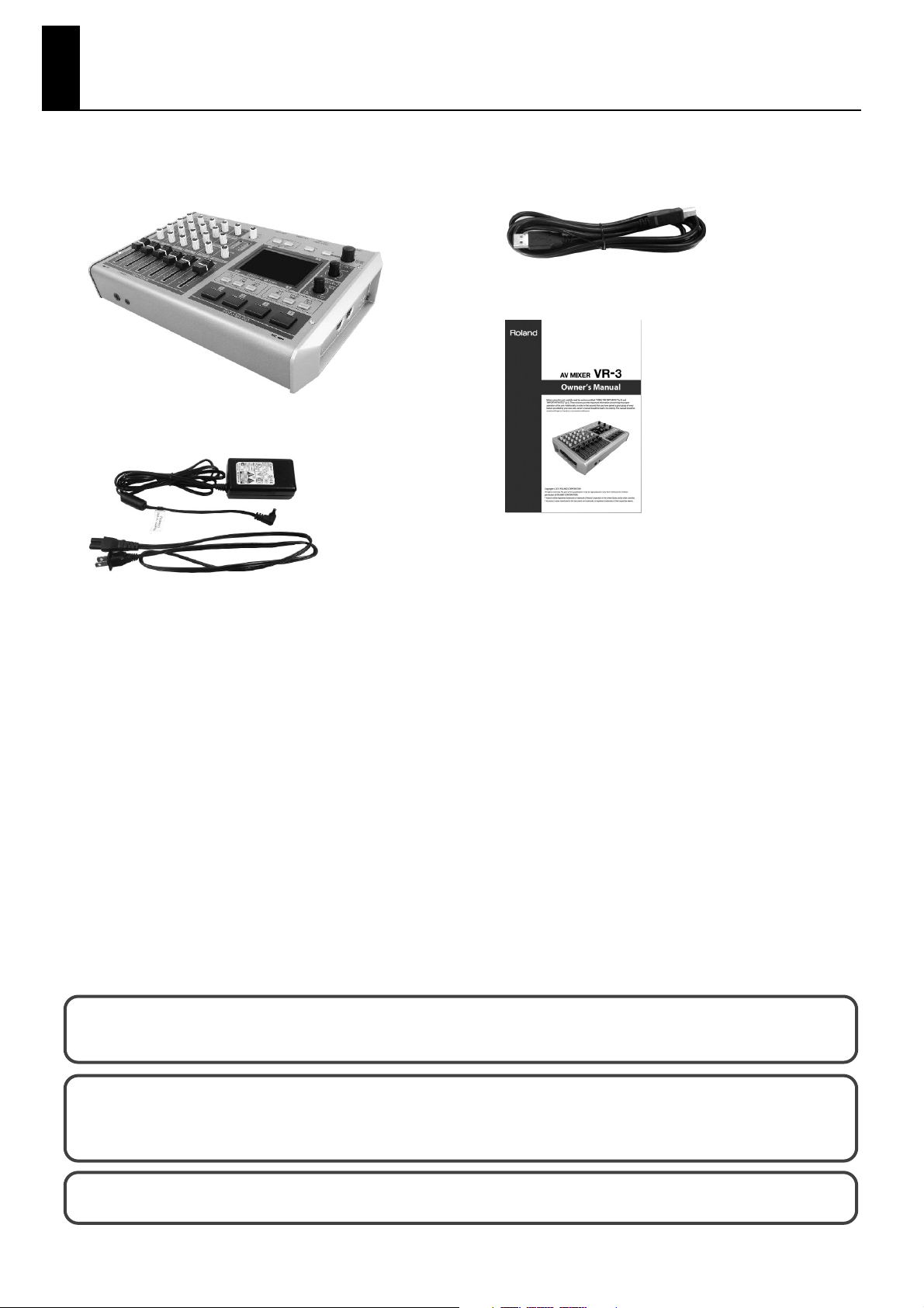
Check the included items
The following items are included. Please make sure that all items are present. If anything is missing, please contact your dealer.
VR-3 itself
fig.VR3-itself.eps
AC adaptor and power cord
fig.PSB1U.eps
USB cable (A type - B type)
fig.USB-cable.eps
Owner’s manual (this document)
fig.owners-manual.eps
The explanations in this manual include illustrations that depict what should typically be shown by the display. Note, however,
that your unit may incorporate a newer, enhanced version of the system, so what you actually see in the display may not always
match what appears in the manual.
This product is using open source license (GPL/LGPL) software. You have the right to acquire, modify and distribute the source
code for this open source license software. You can obtain the open source license source code used in this product by
downloading it from the following website.
http://www.roland.com/support/gpl/
MMP (Moore Microprocessor Portfolio) refers to a patent portfolio concerned with microprocessor architecture, which was
developed by Technology Properties Limited (TPL). Roland has licensed this technology from the TPL Group.
3
Page 4
USING THE UNIT SAFELY
Used for instructions intended to alert
the user to the risk of death or severe
injury should the unit be used
improperly.
Used for instructions intended to alert
the user to the risk of injury or material
damage should the unit be used
improperly.
* Material damage refers to damage or
other adverse effects caused with
respect to the home and all its
furnishings, as well to domestic
animals or pets.
002c
• Do not open (or modify in any way) the unit or its AC
adaptor.
.................................................................................................................................
003
• Do not attempt to repair the unit, or replace parts within it
(except when this manual provides specific instructions
directing you to do so). Refer all servicing to your retailer,
the nearest Roland Service Center, or an authorized Roland
distributor, as listed on the “Information” sheet.
.................................................................................................................................
004
• Never install the unit in any of the following locations.
• Subject to temperature extremes (e.g., direct sunlight in
an enclosed vehicle, near a heating duct, on top of heatgenerating equipment); or are
• Damp (e.g., baths, washrooms, on wet floors); or are
• Exposed to steam or smoke; or are
• Subject to salt exposure; or are
• Humid; or are
• Exposed to rain; or are
• Dusty or sandy; or are
• Subject to high levels of vibration and shakiness.
.................................................................................................................................
007
• Make sure you always have the unit placed so it is level and
sure to remain stable. Never place it on stands that could
wobble, or on inclined surfaces.
.................................................................................................................................
008c
• Be sure to use only the AC adaptor supplied with the unit.
Also, make sure the line voltage at the installation matches
the input voltage specified on the AC adaptor’s body. Other
AC adaptors may use a different polarity, or be designed for
a different voltage, so their use could result in damage,
malfunction, or electric shock.
.................................................................................................................................
008e
• Use only the attached power-supply cord. Also, the supplied
power cord must not be used with any other device
The symbol alerts the user to important instructions
or warnings.The specific meaning of the symbol is
determined by the design contained within the
triangle. In the case of the symbol at left, it is used for
The symbol alerts the user to items that must never
be carried out (are forbidden). The specific thing that
must not be done is indicated by the design contained
within the circle. In the case of the symbol at left, it
means that the unit must never be disassembled.
The ● symbol alerts the user to things that must be
carried out. The specific thing that must be done is
indicated by the design contained within the circle. In
the case of the symbol at left, it means that the powercord plug must be unplugged from the outlet.
009
• Do not excessively twist or bend the power cord, nor place
heavy objects on it. Doing so can damage the cord,
producing severed elements and short circuits. Damaged
cords are fire and shock hazards!
.................................................................................................................................
010
• This unit, either alone or in combination with an amplifier
and headphones or speakers, may be capable of producing
sound levels that could cause permanent hearing loss. Do
not operate for a long period of time at a high volume level,
or at a level that is uncomfortable. If you experience any
hearing loss or ringing in the ears, you should immediately
stop using the unit, and consult an audiologist.
.................................................................................................................................
011
• Do not place containers containing liquid on this product.
Never allow foreign objects (e.g., flammable objects, coins,
wires) or liquids (e.g., water or juice) to enter into this
product. Doing so may cause short circuits, faulty operation,
or other malfunctions.
.................................................................................................................................
012b
• Immediately turn the power off, remove the AC adaptor
from the outlet, and request servicing by your retailer, the
nearest Roland Service Center, or an authorized Roland
distributor, as listed on the “Information” sheet when:
• The AC adaptor, the power-supply cord, or the plug has
been damaged; or
• If smoke or unusual odor occurs
• Objects have fallen into, or liquid has been spilled onto
the unit; or
• The unit has been exposed to rain (or otherwise has
become wet); or
• The unit does not appear to operate normally or exhibits
a marked change in performance.
.................................................................................................................................
013
• In households with small children, an adult should provide
supervision until the child is capable of following all the
rules essential for the safe operation of the unit.
.................................................................................................................................
.................................................................................................................................
4
Page 5
USING THE UNIT SAFELY
014
• Protect the unit from strong impact.
(Do not drop it!)
.................................................................................................................................
015
• Do not force the unit’s power-supply cord to share an outlet
with an unreasonable number of other devices. Be
especially careful when using extension cords—the total
power used by all devices you have connected to the
extension cord’s outlet must never exceed the power rating
(watts/amperes) for the extension cord. Excessive loads can
cause the insulation on the cord to heat up and eventually
melt through.
.................................................................................................................................
016
• Before using the unit in a foreign country, consult with your
retailer, the nearest Roland Service Center, or an authorized
Roland distributor, as listed on the “Information” sheet.
.................................................................................................................................
101b
• The unit and the AC adaptor should be located so their
location or position does not interfere with their proper
ventilation.
.................................................................................................................................
102c
• Always grasp only the plug on the AC adaptor cord when
plugging into, or unplugging from, an outlet or this unit.
.................................................................................................................................
103b
• At regular intervals, you should unplug the AC adaptor and
clean it by using a dry cloth to wipe all dust and other
accumulations away from its prongs. Also, disconnect the
power plug from the power outlet whenever the unit is to
remain unused for an extended period of time. Any
accumulation of dust between the power plug and the
power outlet can result in poor insulation and lead to fire.
.................................................................................................................................
104
• Try to prevent cords and cables from becoming entangled.
Also, all cords and cables should be placed so they are out
of the reach of children.
.................................................................................................................................
106
• Never climb on top of, nor place heavy objects on the unit.
.................................................................................................................................
107c
• Never handle the AC adaptor or its plugs with wet hands
when plugging into, or unplugging from, an outlet or this
unit.
.................................................................................................................................
108b
• Before moving the unit, disconnect the AC adaptor and all
cords coming from external devices.
.................................................................................................................................
109b
• Before cleaning the unit, turn off the power and unplug the
AC adaptor from the outlet (p.8 ).
.................................................................................................................................
110b
• Whenever you suspect the possibility of lightning in your
area, disconnect the AC adaptor from the outlet.
.................................................................................................................................
118e
• If you remove the screw from the ground terminal, be sure
to replace it; don't leave it lying around where it could
accidentally be swallowed by small children. When refastening the screw, make that it is firmly fastened, so it won't
come loose.
.................................................................................................................................
120
• Always turn the phantom power off when connecting any
device other than condenser microphones that require
phantom power. You risk causing damage if you mistakenly
supply phantom power to dynamic microphones, audio
playback devices, or other devices that don't require such
power. Be sure to check the specifications of any microphone you intend to use by referring to the manual that
came with it.\n\n
(This unit's phantom power: +48 V DC, 14 mA Max)
..........................................................................................................
5
Page 6

IMPORTANT NOTES
Power Supply
301
• Do not connect this unit to same electrical outlet that is being used by
an electrical appliance that is controlled by an inverter (such as a
refrigerator, washing machine, microwave oven, or air conditioner), or
that contains a motor. Depending on the way in which the electrical
appliance is used, power supply noise may cause this unit to
malfunction or may produce audible noise. If it is not practical to use a
separate electrical outlet, connect a power supply noise filter
between this unit and the electrical outlet.
302
• The AC adaptor will begin to generate heat after long hours of
consecutive use. This is normal, and is not a cause for concern.
307
• Before connecting this unit to other devices, turn off the power to all
units. This will help prevent malfunctions and/or damage to monitors
or other devices.
309
• With the factory settings, the VR-3's power will automatically be
switched off if all these 3 statuses continue 240 minutes.
• No operation is carried out (including remote control operation).
• No video signal is input.
• No audio signal higher than -64 dBu is input.
* You can disable the AUTO OFF feature by going to the [SYSTEM]
menu and setting [AUTO OFF] to [OFF]. Refer to “Menu Operations” (p.
44) and “SYSTEM Menu” (p. 47).
* The settings you were editing will be lost when the power is turned
off. If you want to keep you settings, you must save your settings
before turning the power off.
Placement
351
• Using the unit near power amplifiers (or other equipment containing
large power transformers) may induce hum. To alleviate the problem,
change the orientation of this unit; or move it farther away from the
source of interference.
352a
• This device may interfere with radio and television reception. Do not
use this device in the vicinity of such receivers.
352b
• Noise may be produced if wireless communications devices, such as
cell phones, are operated in the vicinity of this unit. Such noise could
occur when receiving or initiating a call, or while conversing. Should
you experience such problems, you should relocate such wireless
devices so they are at a greater distance from this unit, or switch them
off.
354a
• Do not expose the unit to direct sunlight, place it near devices that
radiate heat, leave it inside an enclosed vehicle, or otherwise subject it
to temperature extremes. Excessive heat can deform or discolor the
unit.
355b
• When moved from one location to another where the temperature
and/or humidity is very different, water droplets (condensation) may
form inside the unit. Damage or malfunction may result if you
attempt to use the unit in this condition. Therefore, before using the
unit, you must allow it to stand for several hours, until the condensation has completely evaporated.
360
• Depending on the material and temperature of the surface on which
you place the unit, its rubber feet may discolor or mar the surface. You
can place a piece of felt or cloth under the rubber feet to prevent this
from happening. If you do so, please make sure that the unit will not
slip or move accidentally.
361
• Do not put anything that contains water on this unit. Also, avoid the
use of insecticides, perfumes, alcohol, nail polish, spray cans, etc., near
the unit. Swiftly wipe away any liquid that spills on the unit using a
dry, soft cloth.
Maintenance
401a
• For everyday cleaning wipe the unit with a soft, dry cloth or one that
has been slightly dampened with water. To remove stubborn dirt, use
a cloth impregnated with a mild, non-abrasive detergent. Afterwards,
be sure to wipe the unit thoroughly with a soft, dry cloth.
402
• Never use benzine, thinners, alcohol or solvents of any kind, to avoid
the possibility of discoloration and/or deformation.
Additional Precautions
poke-mon
• This unit allows you to switch images sat high speed. For some
people, viewing such images can cause headache, nausea, or other
discomfort. Do not use this unit to create video that might cause
these types of health problems.Roland Corporation will accept no
responsibility for any such health problems that may occur in yourself
or in viewers.
553
• Use a reasonable amount of care when using the unit’s buttons,
sliders, or other controls; and when using its jacks and connectors.
Rough handling can lead to malfunctions.
554
• Never strike or apply strong pressure to the display.
556
• When connecting / disconnecting all cables, grasp the connector
itself—never pull on the cable. This way you will avoid causing shorts,
or damage to the cable’s internal elements.
558a
• To avoid disturbing your neighbors, try to keep the unit's volume at
reasonable levels. You may prefer to use headphones, so you do not
need to be concerned about those around you (especially when it is
late at night).
559a
• When you need to transport the unit, package it in the box (including
padding) that it came in, if possible. Otherwise, you will need to use
equivalent packaging materials.
562
• Some connection cables contain resistors. Do not use cables that
incorporate resistors for connecting to this unit. The use of such
cables can cause the sound level to be extremely low, or impossible to
hear. For information on cable specifications, contact the manufacturer of the cable.
Others
988
• Security Slot
http://www.kensington.com/
6
Page 7

Contents
Power Supply .......................................................................................................................8
Connecting the AC Adapter .................................................................................................................................................. 8
Turning the Power On ............................................................................................................................................................. 9
Turning the Power Off .............................................................................................................................................................9
Names of Things and What They Do ................................................................................10
Top Panel....................................................................................................................................................................................10
Audio Mixer Section....................................................................................................................................................................... 11
Video Select Section....................................................................................................................................................................... 12
Rear Panel...................................................................................................................................................................................14
Left Side Panel ..........................................................................................................................................................................15
Right Side Panel .......................................................................................................................................................................15
Front Panel.................................................................................................................................................................................15
Signal Flow................................................................................................................................................................................. 16
Connecting External Equipment ......................................................................................17
Connecting Video Sources...................................................................................................................................................18
Connecting Audio Sources ..................................................................................................................................................18
Connecting a Computer .......................................................................................................................................................20
Connecting Output Equipment .........................................................................................................................................21
Connecting a Projector or Recording Unit............................................................................................................................. 21
Connecting an Amplifier, Speakers, and Recorders ...........................................................................................................21
Connecting a Preview Monitor ..................................................................................................................................................21
Basic Operation..................................................................................................................22
Switching the Video ...............................................................................................................................................................22
Automatically Switching the Video ..................................................................................................................................24
Freezing the Final Output.....................................................................................................................................................24
Applying a Fade to Final Video Output...........................................................................................................................24
Adjusting the Audio Balance...............................................................................................................................................25
Adjusting the Final Audio Output .....................................................................................................................................28
Compositing the Picture ...................................................................................................29
Compositing Using Picture-in-Picture .............................................................................................................................29
Adjusting the Position and Size of the Inset Screen........................................................................................................... 31
Compositing Using Split .......................................................................................................................................................32
Compositing Using Luminance Key/Chroma Key .......................................................................................................34
Compositing Using Luminance Key......................................................................................................................................... 34
Compositing Using Chroma Key ...............................................................................................................................................36
Performing Output from the USB Port ............................................................................38
Connecting a Computer .......................................................................................................................................................38
Performing Output to a Computer ...................................................................................................................................40
Using Other Features ........................................................................................................41
Changing the Size and Position of Overlay Display....................................................................................................41
Applying Effects to Audio.....................................................................................................................................................41
Saving/Recalling Settings.....................................................................................................................................................43
Returning to the Factory-default State............................................................................................................................43
Switching Between NTSC and PAL....................................................................................................................................43
Menu Operations and Menu List ......................................................................................44
Menu Operations..................................................................................................................................................................... 44
Menu List ....................................................................................................................................................................................45
Appendices ........................................................................................................................48
Main Specifications.................................................................................................................................................................48
About Remote Control ..........................................................................................................................................................48
Troubleshooting ......................................................................................................................................................................49
Dimensions ................................................................................................................................................................................50
7
Page 8
Power Supply
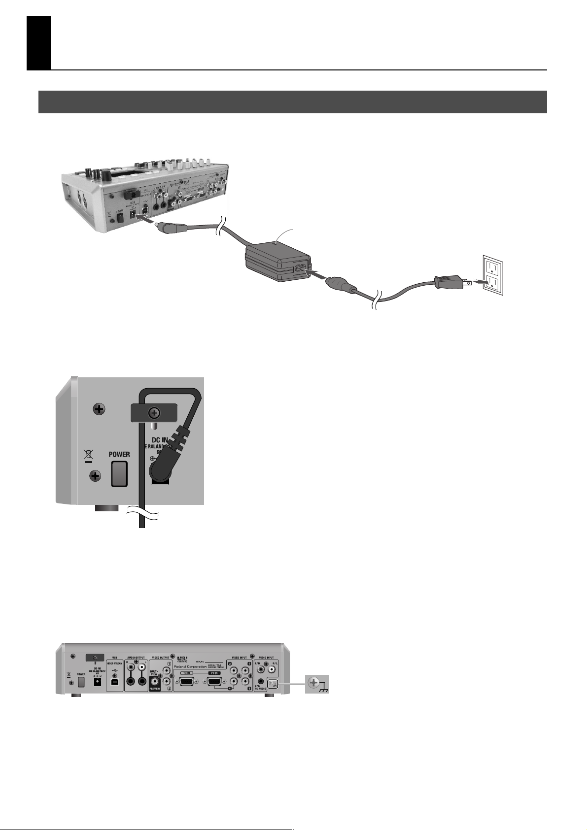
Connecting the AC Adapter
Connect the AC adapter as shown in the figure below. Position the AC adapter so that the surface where the indicator is located
(see figure) is facing up. Connecting the AC adapter to a power outlet makes the indicator light up.
fig.connect-PSB7U.eps
Indicator
Cord Hook
To prevent the inadvertent disruption of power to your unit (should the plug be pulled out accidentally), and to avoid applying
undue stress to the AC adaptor jack, anchor the power cord using the cord hook, as shown in the illustration.
fig.cord-hook.eps
Caution Regarding the Power Supply
Depending on the circumstances of a particular setup, you may experience a discomforting sensation, or perceive that the
surface feels gritty to the touch when you touch this device, microphones connected to it, or the metal portions of other objects.
This is due to an infinitesimal electrical charge, which is absolutely harmless. However, if you are concerned about this, connect
the ground terminal (see figure) with an external ground. When the unit is grounded, a slight hum may occur, depending on the
particulars of your installation. If you are unsure of the connection method, contact the nearest Roland Service Center, or an
authorized Roland distributor, as listed on the "Information" sheet.
fig.earth-terminal.eps
Unsuitable places for connection
• Water pipes (may result in shock or electrocution)
• Gas pipes (may result in fire or explosion)
• Telephone-line ground or lightning rod (may be dangerous in the event of lightning)
8
Page 9
Turning the Power On
* Once the connections have been completed (p. 8,), turn on power to your various devices in the order specified. By turning on devices in the
wrong order, you risk causing malfunction and/or damage to speakers and other devices.
* This unit is equipped with a protection circuit. A brief interval (a few seconds) after power up is required before the unit will operate normally.
* Always make sure to have the volume level turned down before switching on power. Even with the volume all the way down, you may still hear
some sound when the power is switched on, but this is normal, and does not indicate a malfunction.
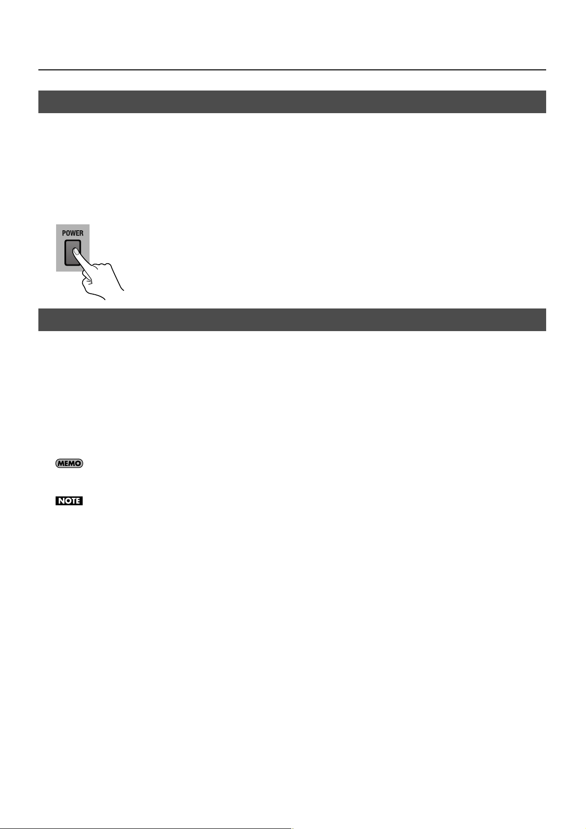
Make sure the power cable is securely inserted, then press the [POWER] button located on the rear panel. The buttons and
indicators on the top panel flash, and the VR-3 starts up.
fig.power-button.eps
Turning the Power Off
Power Supply
Press the [POWER] button on the rear panel. The buttons and indicators on the top panel go dark, and the power to the VR-3 is
switched off.
About AUTO OFF
When all of the conditions described below continue for 240 minutes or longer, the AUTO OFF feature automatically turns off
power of the VR-3.
• No operation is carried out (including remote control operation).
• No video signal is input.
• No audio signal higher than -64 dBu is input.
You can disable the AUTO OFF feature by going to the [SYSTEM] menu and setting [AUTO OFF] to [OFF]. Refer to “Menu Operations” (p. 44) and
“SYSTEM Menu” (p. 47).
The settings you were editing will be lost when the power is turned off. If you want to keep you settings, you must save your settings before
turning the power off.
9
Page 10
Names of Things and What They Do
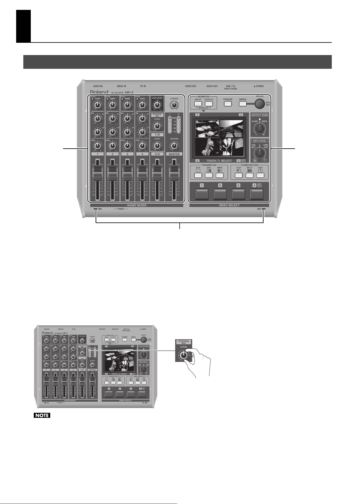
Top Panel
fig.top-panel.eps
1 2
3
1. Audio Mixer Section (p. 11)
This section is for audio mixing. Use the dials and faders to adjust the input sensitivity, output levels, and other values for each
channel.
2. Video Select Section (p. 12)
This section is for switching and compositing video. Use the buttons and dials to select transition effects and compositing modes.
3. Internal Stereo Microphones
Internal microphones for picking up ambient audio are located on the left and right sides of the top panel. To adjust the level, use
[LEVEL] dial of [INTERNAL MIC].
fig.int-mic-level.eps
When adjusting buttons or faders, some handling noise may be heard in the internal microphones.
10
Page 11
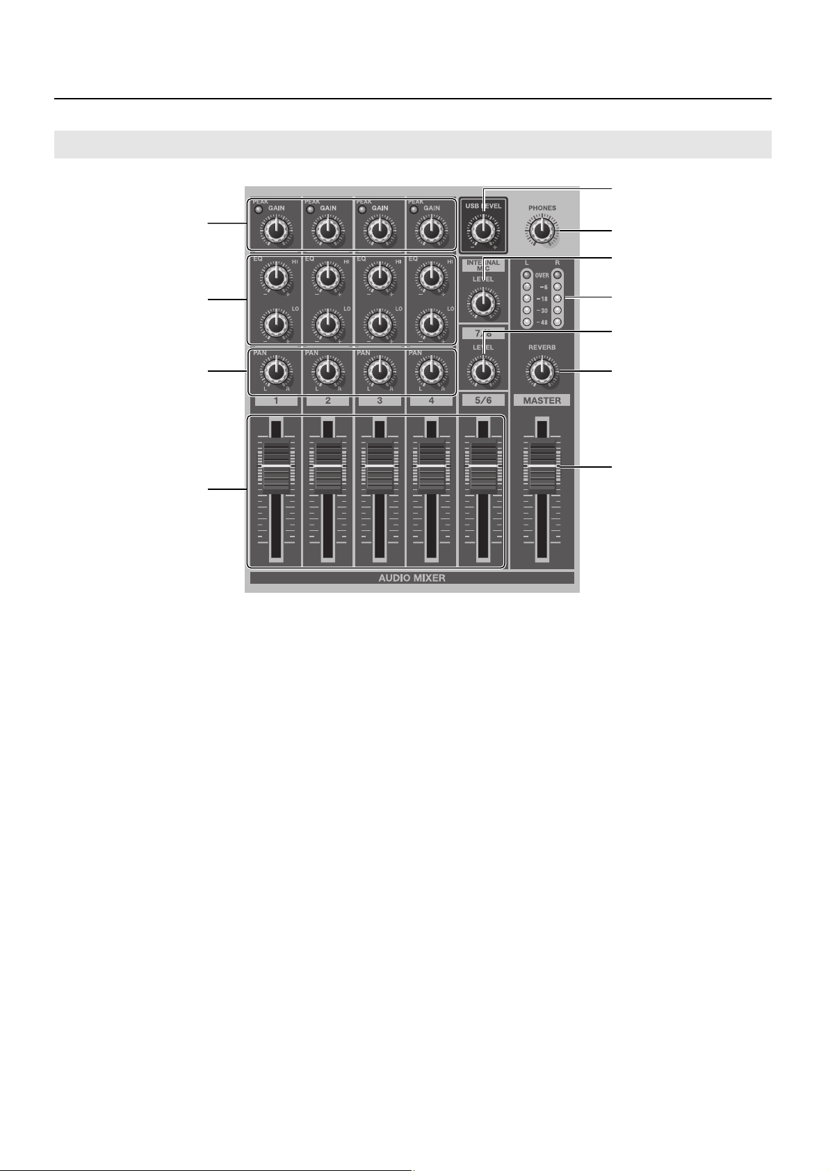
Audio Mixer Section
fig.audio-mix-section.eps
Names of Things and What They Do
5
1
2
3
4
1. GAIN Dials and PEAK Indicators
Use the [GAIN] dials to adjust the input sensitivity for
channels 1 through 4. When the volume level exceeds the
maximum input level, the corresponding [PEAK] indicator
lights up. Excessive input volume may result in clipping or
distortion. Set the [GAIN] dials for adequate audio level
without clipping.
6
7
8
9
10
11
7. INTERNAL MIC LEVEL Dial (p. 26)
This adjusts the level for the internal microphones.
8. Level Meter (p. 28)
This displays the audio output level. If [OVER] lights up,
distortion might occur. Turn down the [MASTER] level if the
[OVER] indicator lights up.
2. EQ Dials (p. 26)
Use the [Hi] dials to emphasize or attenuate the high band.
Use the [Lo] dials to emphasize or attenuate the low band.
3. PAN Dials (p. 26)
These adjust the stereo position of the respective channels.
4. Channel Faders (p. 25)
These faders adjust the amount of signal being sent from
each channel and the amount of signal each channel sends
to the final output (MASTER).
5. USB LEVEL Dial (p. 40)
This adjusts the audio level for USB output.
6. PHONES Dial
This adjusts the level for headphones output.
9. 7/8 LEVEL Dial
This adjusts the level of audio input coming from a computer
connected to the [7/8] connector on the rear panel.
10. REVERB Dial (p. 28)
This adjusts the amount of reverb applied to output.
11. MASTER Fader (p. 28)
This adjusts the level for final output.
11
Page 12
Names of Things and What They Do
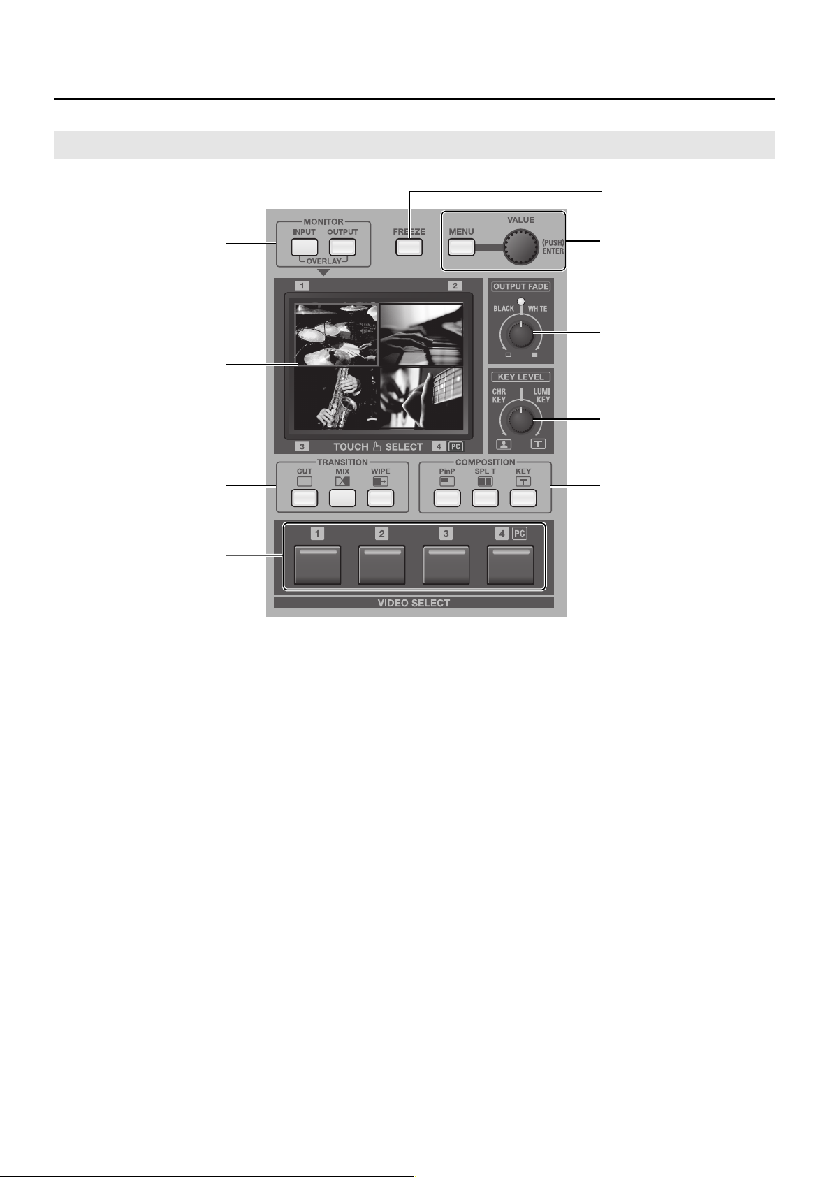
Video Select Section
fig.video-mix-section.eps
5
1
2
3
4
1. MONITOR Buttons
These switch the view mode for the monitor. Choose a mode
from the followings.
• [INPUT]
This displays the inputs from the respective source devices.
• [OUTPUT]
This displays the result of video mixing on the VR-3 (the final
output).
• OVERLAY
When the [INPUT] button and [OUTPUT] button are pressed
simultaneously, the output picture is overlaid on a four-way split
screen of the input.
2. Monitor
When the view mode is set to [INPUT], you can switch the
video by touching the screen. When the mode is set to
[OUTPUT], you can adjust the position and size of the
Picture-in-Picture (PinP) inset screen. Menus are also
displayed here.
* During two-screen compositing, the background picture can be
switched by touching the screen.
3. TRANSITION Buttons (p. 22)
You can select a transition effect for the video using these
buttons. When switching from one video source to another,
this effect will be applied during the transition.
6
7
8
9
4. VIDEO SELECT Buttons (p. 23)
You can use these buttons to switch the video instead of the
touch panel.
* During two-screen compositing, use buttons [1] through [4] to
switch the inset screen or foreground picture.
5. FREEZE Button (p. 24)
Use this button to freeze the final output image.
6. MENU Button and VALUE Dial (p. 44)
Use the [MENU] button to call up various menus on the VR-3.
The menus are displayed on the monitor.
The [VALUE] dial is for changing settings. Press the
[VALUE] dial to apply a new setting (ENTER).
* You can change a setting value up or down by ten units at a time
by holding the [VALUE] dial down while you turn it.
7. OUTPUT FADE Dial (p. 24)
Use this when you want to apply a fade-in or fade-out to
final output from the VR-3. Turning the dial
counterclockwise applies a black fade, and turning it
clockwise applies a white fade. Applying a fade makes the
indicator above the dial flash.
12
Page 13

Names of Things and What They Do
8. KEY LEVEL Dial (p. 35, p. 37)
This adjusts the degree of the extraction (removal) in key compositing. The extraction color for key compositing differs according
to the direction in which you turn the dial. At the center position, no extraction at all occurs. (The background video is not visible.)
Turning the dial all the way clockwise or counterclockwise enables complete extraction, and the foreground picture is not visible.
Turn the dial slowly to find the optimal degree of extraction.
• [LUMI KEY] Turning the dial clockwise enables luminance-key compositing. Black or white backgrounds are extracted.
• [CHR KEY] Turning the dial counterclockwise enables chroma-key compositing. Blue or green backgrounds are extracted.
* In the factory-default state, black is the extraction color for luminance-key compositing, and blue is the extraction color for chroma-key
composition. You can use the menus to change the extraction color. Refer to “Menu Operations” (p. 44) and “VIDEO Menu” (p. 45).
Examples of Key Compositing
fig.key-example.eps
Black (or White)
Luminance Key
Blue (or Green)
Chroma Key
9. COMPOSITION Buttons (p. 29, p. 33, p. 34)
You can select a composition mode from below using buttons here.
• [PinP] This performs Picture-in-Picture compositing.
• [SPLIT] This performs compositing with the screen split vertically or horizontally.
• [KEY] This performs compositing using chroma key or luminance key.
13
Page 14
Names of Things and What They Do
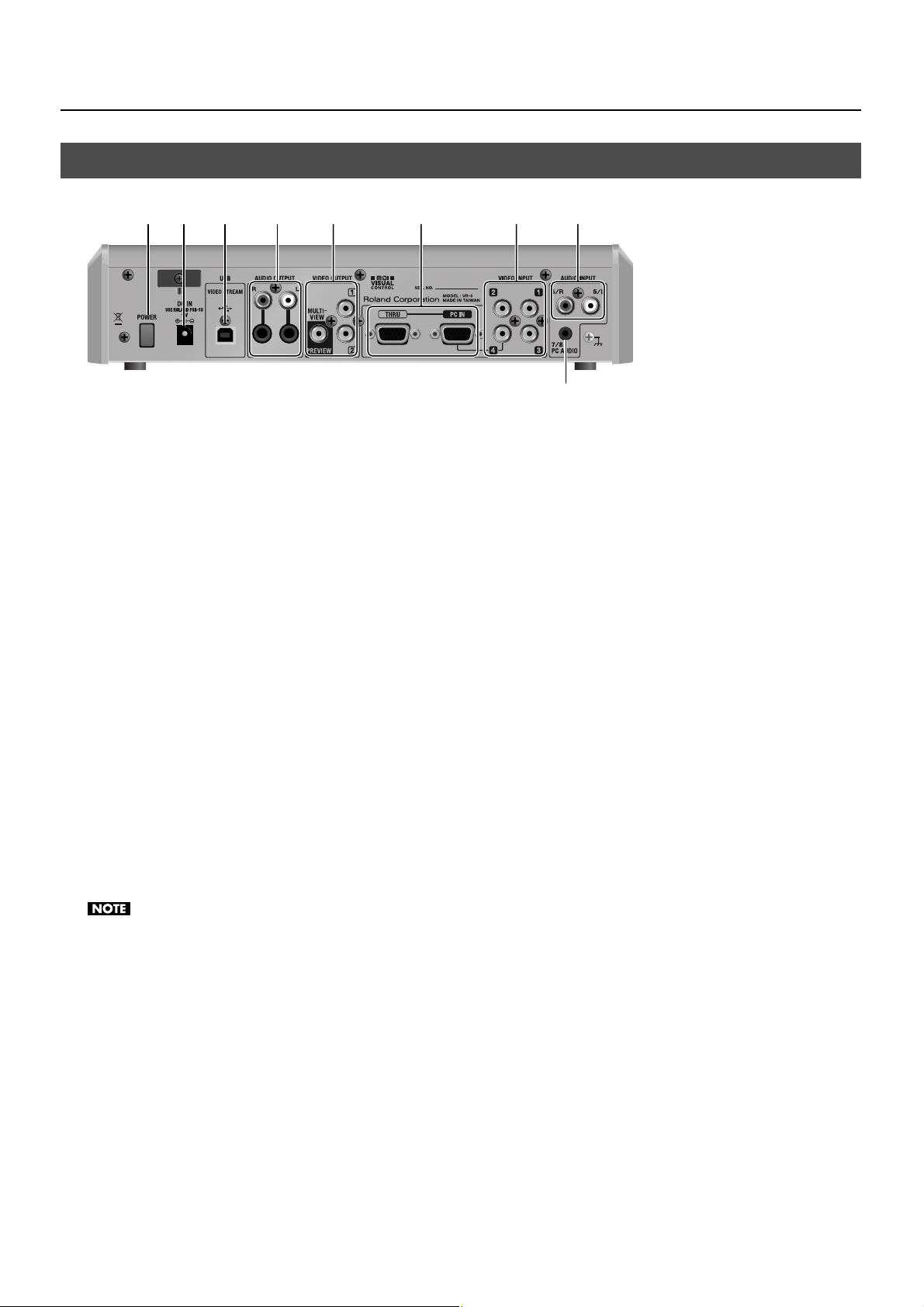
Rear Panel
fig.rear-panel.eps
1 2 34 5 6 7 8
1. POWER Button
This switches the power to the VR-3 on and off.
2. DC IN Connector
This is for connecting the included AC adapter.
* Use the cord hook to secure the AC adapter cord in place (p. 8).
9
3. USB Port
You can use this to output the results of video and audio mixing on the VR-3 to a computer.
4. AUDIO OUTPUT Connectors
These output the results of audio mixing. Connect output equipment (an amplifier or speakers) and recording equipment (such
as a video recorder).
5. VIDEO OUTPUT Connectors
These output the results of video mixing. Connect output equipment (such as a projector) and recording equipment (such as a
video recorder).
The PREVIEW connector is for connecting a preview monitor.
6. PC IN and THRU Connectors
You can connect RGB output from a computer to the PC IN connector and input logos, text, or still images. Input made via this
connector is assigned to channel 4. When composite input and RGB input are made to channel 4 at the same time, the RGB input
takes priority.
The THRU connector is for connecting a computer monitor.
Small text from a computer may not be shown clearly on the final output. If you input text, the font size should be big enough.
7. VIDEO INPUT Connectors
Use these to connect video cameras or other video sources. When composite input and RGB input are made to channel 4 at the
same time, the RGB input takes priority.
* You can use the menus to lock the channel-4 input to composite or RGB. Go to the [SYSTEM] menu and select [PC IN], then use [CH4 INPUT
SOURCE] to select [PC IN] or [VIDEO]. Refer to “Menu Operations” (p. 44) and “SYSTEM Menu” (p. 47).
8. AUDIO INPUT Connectors
These are for connecting the audio output of video players or other source equipment. Input made via the RCA connectors is
assigned to channels 5/6.
9. PC AUDIO Connector
This is for connecting audio output from a computer. Input from the computer is assigned to channels 7/8.
14
Page 15
Names of Things and What They Do
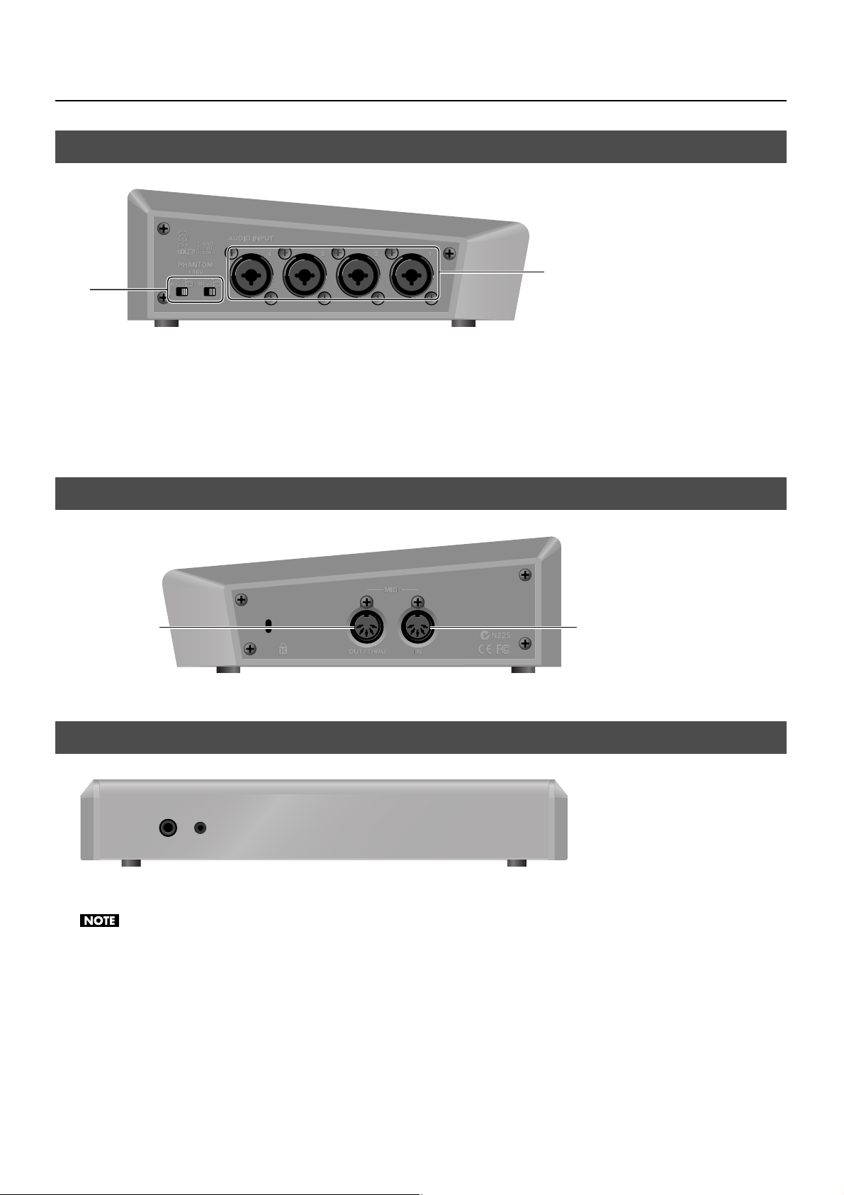
Left Side Panel
fig.right-side-panel.eps
2
1
1. PHANTOM +48V Switch (p. 19)
This switches the phantom power of the AUDIO INPUT (XLR/TRS) connectors on and off. The unit has a switch for channels 1/2
and a switch for channels 3/4.
2. AUDIO INPUT (XLR/TRS) Connectors
These are for connecting microphones or an external audio mixer, or other audio sources. Input made via these connectors is
assigned to channels 1 through 4.
Right Side Panel
fig.left-side-panel.eps
OUT/THRU
MIDI IN and MIDI OUT/THRU connectors are equipped here. You can connect external MIDI devices to remote control the VR-3.
Refer to “About Remote Control” (p. 48).
IN
Front Panel
fig.front-panel.eps
Two headphones (PHONES) connectors are located here. You can use these to connect standard-type (1/4-inch) headphones and
mini-stereo headphones.
The volume levels for the two PHONES connectors cannot be adjusted independently. Operating the [PHONES] dial changes the volume for both
simultaneously.
15
Page 16
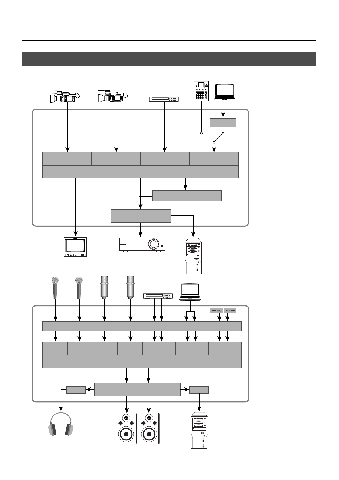
Names of Things and What They Do
Signal Flow
Signal flow inside the VR-3 is as shown in the figure below.
fig.signal-flow.eps
RGB
Converter
12
3
4
Preview
Video Mixer
Video Fader
321
PinP / Split / Key
USB
4
Video
16
12
Level Level
Audio Effects
3
4
5/6 7/8
Audio Mixer
Master Fader / Audio Effects
INT MIC
Audio
USB
Page 17
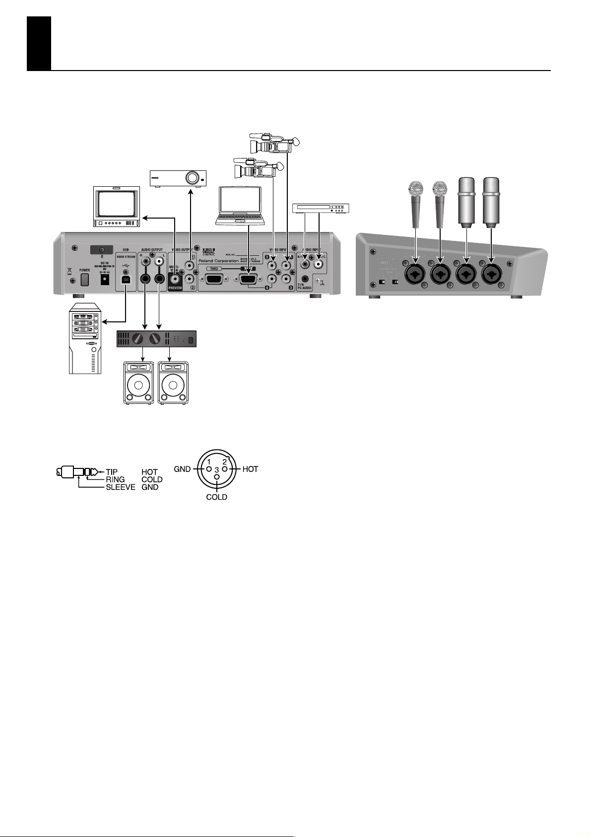
Connecting External Equipment
You can connect external equipment as shown below. For information on specific connections, refer to the following pages.
* To prevent malfunction and/or damage to speakers or other devices, always turn down the volume, and turn off the power on all devices before
making any connections.
fig.peripheral-connection.eps
This unit is equipped with balanced (XLR/TRS) type jacks. Wiring diagrams for these jacks are shown below. Make connections
after first checking the wiring diagrams of other equipment you intend to connect.
fig.XLR-TRS.eps
Howling could be produced depending on the location of microphones relative to speakers. This can be remedied by:
1. Changing the orientation of the microphone(s).
2. Relocating microphone(s) at a greater distance from speakers.
3. Lowering volume levels.
17
Page 18

Connecting External Equipment
Connecting Video Sources
Connect video cameras, DVD players, and other sources to the VIDEO INPUT connectors.
* Channel 4 has a composite connector and a RGB connector, and when input is made through both at the same time, the RGB input takes priority.
fig.connect-video-source.eps
Player
Connecting Audio Sources
* When connection cables with resistors are used, the volume level of equipment connected to the audio inputs may be low. If this happens, use
connection cables that do not contain resistors.
Connecting Audio Players
Connect the audio output from video players, CD players, and other devices to the AUDIO INPUT connectors.
* When making the connection, be careful to connect the left and right lines correctly.
fig.connect-DVD-player.eps
Player
18
Page 19

Connecting External Equipment
Connecting Microphones
Connect microphones to the AUDIO INPUT connectors on the left side panel. When you are connecting a condenser microphone
or other device that requires a supply of +48 V phantom power, set the [PHANTOM +48V] switch to ON.
* The unit has one [PHANTOM +48V] switch for channels 1/2 and one for channels 3/4. Set the switch to correspond to the connector where the
device is connected.
fig.connect-mic.eps
Dynamic Mic Condenser Mic
When you are connecting a dynamic microphone or other device that does not require power supply, be sure to set the [PHANTOM +48V] switch
to OFF. Making the connection while the switch is left set to ON may cause malfunction. (Phantom power on the VR-3: +48 VDC/maximum 14 mA
per channel)
When one or both of the [PHANTOM +48V] switches is set to ON, current consumption increases by approximately 200 mA per switch.
Connecting an External Audio Mixer
When the number of audio channels is large, such as when you are recording a band performance, make the connections to the
AUDIO INPUT connectors via an external audio mixer.
fig.connect-audio-mixer.eps
Audio Mixer
19
Page 20

Connecting External Equipment
Connecting a Computer
Connect the external output of the computer to the PC IN connector. A built-in scan converter converts the incoming RGB signal
to a video signal. When you are connecting a monitor for a desktop computer, use the THRU connector.
* The resolutions supported by the internal scan converter are as shown in the table. Input signals at a supported resolution.
* When connecting audio output from the computer to the PC AUDIO connector, use a mini-stereo cable. To adjust the volume level, use the [7/8
LEVEL] dial.
fig.connect-PC.eps
Supported Resolutions
SVGA Mac16inch
XGA
Mac21inch
WideXGA
SXGA
* The refresh rate is the maximum value of each resolution.
The PC IN connector on the VR-3 is D-Sub 15-pin. If necessary, you can use a DVI-VGA adaptor to connect your DVI output to the D-Sub 15-pin
connector. A DVI-VGA adapter is not included. Please purchase separately.
800 x 600 / 120Hz 832 x 624 / 75Hz
1024 x 768 / 80Hz 1152 x 864 / 75Hz
1152 x 870 / 75Hz
1280 x 768 / 75Hz 1280 x 800 / 75Hz
1280 x 1024 / 75Hz
XGA+
HD720p
WXGA
FWXGA
1280 x 720 / 60Hz
1366 x 768 / 75Hz
When displaying video from your PC that has intense motion, the output video may display some flicker or visual corruption. This is called tearing,
and does not indicate malfunction.
At the [SYSTEM] menu, under [PC IN], when [INPUT RESOLUTION] is set to [AUTO], the resolution of the input signal is detected automatically. If
the resolution is not detected correctly, set the resolution manually.
20
Page 21

Connecting Output Equipment
Connecting a Projector or Recording Unit
Connect projectors and recorders at the VIDEO OUTPUT connectors.
fig.connect-projector.eps
Recorder
Connecting an Amplifier, Speakers, and Recorders
Connecting External Equipment
Projector
Connect an amplifier, speakers or a recorder to the AUDIO OUTPUT connectors. The VR-3 has standard TRS and RCA type AUDIO
OUTPUT connectors, and the same audio is output from both types.
* Nominal output level of the VR-3 is -10 dBu. Connect equipment that supports input at -10 dBu.
fig.connect-speaker.eps
Recorder
Amp
Connecting a Preview Monitor
A preview monitor connected to the PREVIEW connector displays the same preview screen that appears on the built-in monitor.
The preview video selected using the [MONITOR] buttons is output.
* The monitor connected to the PREVIEW connector does not show the menu screens.
fig.connect-monitor.eps
When you want to display a four-way split screen as shown in the figure above, use the [MONITOR] buttons to select [INPUT].
21
Page 22

Basic Operation
This section describes how to switch (transition) video inputs and mix audio inputs from external sources.
Switching the Video
If a fade is applied to the final output, the video is not output to a projector or other output devices. Adjust the [OUTPUT FADE] dial to its center
position. For information about fades in final output, refer to “Applying a Fade to Final Video Output” (p. 24).
Using the Touch Panel to Switch the Video
1. Display the input from the sources.
At [MONITOR], press the [INPUT] button. The input from the respective source is displayed at [1] through [4]. When the VR-3 starts
up, [1] is selected, and a red border is displayed around the [1] section.
fig.select-input-mode.eps
2. Select a transition effect.
Use the [TRANSITION] buttons to select a transition effect. When you are selecting [CUT], the switch is instantaneous, and no
transition effect is applied. If you want to apply a transition effect, select [MIX] or [WIPE].
fig.select-transition.eps
Start
CUT
MIX
WIPE
• The duration of the transition effect is set at 0.5 seconds by default.
• You can choose from eight types of wipe patterns.
• You can change the direction of the wipe, and also apply soft edges to the wipe.
You can use the menus to modify the items just described and change the settings for the transition effect. Refer to “Menu Operations” (p. 44)
and “VIDEO Menu” (p. 45).
A B
A BAB
A B
A
Finish
No transition effect is applied.
Video sources blend together during
the switch process.
Video sources wipe from one to the other
during the switch process (default : vertical wipe).
22
Page 23

Basic Operation
3. Select a different channel.
Touch the touch panel and choose a channel other than the one currently selected (the channel displayed with a red border). If
you selected [MIX] or [WIPE] in step 2, the transition effect is applied. The newly selected channel is displayed with a green border
while the transition effect is being applied. When the transition effect is completed, the color of the border changes to red.
During overlay display, the touch panel cannot be used to perform switching. Use the [VIDEO SELECT] buttons to switch.
fig.select-channel.eps
4. Check the output video.
At [MONITOR], press the [OUTPUT] button.
fig.select-output-mode.eps
At [MONITOR], you can select OVERLAY mode by pressing the [INPUT] and [OUTPUT] buttons at the same time. In this mode, the output video
overlays on the four-way split picture. This is useful when you want to check the input and output at the same time. You can also use the touch
panel to change the position of the output video. Refer to “Changing the Size and Position of Overlay Display” (p. 41).
Using Buttons to Switch the Video
Instead of using the touch panel, you can perform switching by pressing the [VIDEO SELECT] buttons ([1] through [4]).
The button indicator for the currently selected channel lights up in red. The indicator for the newly selected channel flashes green
while a transition effect is applied. When the applied transition effect ends, the color of the indicator changes to red, and the
indicator stops flashing and lights up steadily.
fig.video-select-button.eps
23
Page 24

Basic Operation
Automatically Switching the Video
At the [VIDEO] menu, going to [TRANSITION] and setting [CH SCAN] to [ON] causes the video on channels 1 through 4 to be
switched automatically. Use [SCAN TIME] to adjust the display time for each respective channel. You can set the time at a value
from 1 to 120 seconds. Refer to “Menu Operations” (p. 44) and “VIDEO Menu” (p. 45).
* Channels that have no video input will be skipped.
* When [CH SCAN] is set to [ON], switching channels manually is not possible.
Freezing the Final Output
You can use the [FREEZE] button to freeze the picture in the final output. Pressing the [FREEZE] button freezes the final output.
Press the button again to return to normal output.
fig.freeze-button.eps
When you are changing the connections between two computers during output, freeze the output before disconnecting the first computer and
then end the freezing after connecting the second computer. This allows you to keep an active PC image on the screen while the VR-3 locks to the
new PC source.
Applying a Fade to Final Video Output
You can apply a fade-in or fade-out to the final output by operating the [OUTPUT FADE] dial. This applies a white or black fade-out
at times when you want to suppress video output, such as during intervals in a band performance.
fig.fade-dial.eps
Fade Out
Turning the [OUTPUT FADE] dial clockwise applies a white fade-out, and turning the dial counterclockwise applies a black fadeout. Applying a fade makes the indicator above the dial flash.
Fade In
Return the [OUTPUT FADE] dial to its center position. The indicator stops flashing and lights steadily and your output video
returns to normal.
24
Page 25

Adjusting the Audio Balance
When the [MASTER] fader is lowered all the way, no audio is output to the speakers or a computer connected via USB. For information on using
the [MASTER] fader to adjust the final output, refer to “Adjusting the Final Audio Output” (p. 28).
Adjusting the Input Sensitivity and Stereo Position
Use the [GAIN] dials to adjust the input sensitivity and the [PAN] dial to adjust the stereo position.
1. Turn down the input sensitivity.
Before mixing your audio sources, first turn the [GAIN] dials counterclockwise to lower the input sensitivity.
fig.gain-low.eps
Basic Operation
2. Raise the faders to the unity position.
Raise the faders for each channel to the unity position (the intermediate position in the area of close-set scale markings).
fig.fader-unity.eps
3. Check incoming audio.
Perform a sound check by having audio sent into your microphones or audio input source.
4. Adjust the input sensitivity.
Gradually turn the [GAIN] dials clockwise to increase the input sensitivity. Raise this just enough that the [PEAK] indicators do not
light up when the output from the source is at maximum volume level.
fig.gain-up.eps
Turning the [GAIN] dials may produce a popping noise or cause momentary audio drop-out, but this is not a malfunction.
25
Page 26

Basic Operation
5. Adjusting the Stereo Position
Use the [PAN] dial to adjust the stereo position to the left or right.
fig.pan-dial.eps
Adjusting the Tone
Use the [HI] dial and [LO] dial in the [EQ] section to adjust the tone.
fig.EQ-dial.eps
1. Emphasize or attenuate the high band.
Turn the [HI] dial to emphasize or attenuate the high section.
2. Emphasize or attenuate the low band.
Turn the [LO] dial to emphasize or attenuate the low section.
Mixing Ambient Sounds into the Output
Using the internal microphones lets you mix the voices of nearby people or other ambient audio into the final output. The two
internal microphones on the VR-3 are installed at the locations shown below. To adjust the level for the internal microphones, go
to [INTERNAL MIC] and use the [LEVEL] dial.
fig.int-mic-location.eps
When the buttons and faders are operated, the internal microphones can pick up the sound of operation.
26
Page 27

Adjusting the Volume Balance for Each Channel
Use the faders for 1 through 4 and for 5/6 to adjust the audio levels of the respective channels.
* When audio is input from a computer via the stereo mini connector, it is assigned to channels 7/8. Channels 7/8 have no fader, and the dial is
used for adjustment.
1. Move the faders to the unity position.
For all channels that have input, move their faders to the unity position.
fig.fader-up.eps
2. Select a channel you want to emphasize.
Select a channel you want to make more prominent, for example, the microphone used by a presenter. Leave the fader for that
channel at the unity position.
Basic Operation
3. Lower the volume levels of the other channels.
Leave the fader untouched for the channel you want to make prominent, and lower the faders for the other channels.
fig.fader-adjust.eps
27
Page 28

Basic Operation
Adjusting the Final Audio Output
You can use the [MASTER] fader to adjust the volume level of the final output. Operate the fader while watching the [MASTER]
indicator.
1. Check the volume level of the final output.
See the [MASTER] indicator to check the volume level. If [OVER] lights up, the volume level may be excessive, resulting in
distortion. If only the indicators up to [-48] or [-30] light up, the volume level may be insufficient. This might worsen the signal-tonoise ratio, resulting in poor-quality speaker output.
fig.master-meter.eps
Too high (red)
Appropriate (orange)
Too low (green)
2. Adjust the volume level.
Move the [MASTER] fader to adjust the volume level. A suitable level is where [-18] to [-6] light up at maximum input.
* If the volume level of speaker output is not suitable even after adjustment so that [-18] to [-6] light up, adjust the volume for the speakers or the
amplifier. Using the [MASTER] fader to carry out further adjustment might result in distortion or degradation of sound quality.
fig.master-fader.eps
3. Apply reverb.
Turn the [REVERB] dial to adjust the amount of reverb.
fig.adjust-reverb.eps
When reverb has been switched off via the menu, no reverb is applied regardless of where the dial is set. Go to the [AUDIO] menu, and at
[REVERB], set [REVERB SW] to [ON]. Refer to “AUDIO Menu” (p. 46).
Excessive reverb may cause feedback/howling to the final output.
Using the menus (p. 44), you can adjust the amount of reverb on each channel individually. Go to the [AUDIO] menu and use [REVERB SEND] to
adjust the amount of reverb. Refer to “AUDIO Menu” (p. 46).
28
Page 29

Compositing the Picture
Compositing Using Picture-in-Picture
Compositing that displays an inset screen on a background is called “Picture-in-Picture” (PinP).
fig.PinP-complete.eps
Inset Screen
Background
* By default, no shadows are added to the inset screen, but you can use the menus to add them. Go to the [VIDEO] menu, and at [PinP], adjust the
setting value for [SHADOW]. Refer to “Menu Operations” (p. 44) and “VIDEO Menu” (p. 45).
* By default, a white border is applied. You can use the menus to change the color and width. Go to the [VIDEO] menu, and at [PinP], adjust the
setting values for [BORDER] and [BORDER COLOR]. Refer to “Menu Operations” (p. 44) and “VIDEO Menu” (p. 45).
* By default, the size of the inset screen is about one-third the size of the background, both vertically and horizontally. For information on
adjusting the position and size of the inset screen, refer to the following section, “Adjusting the Position and Size of the Inset Screen.”
1. On the monitor, display the inputs from the sources.
At [MONITOR], press the [INPUT] button.
2. Select the PinP mode.
Go to [COMPOSITION] and press the [PinP] button to make it light up. [VIDEO SELECT] buttons [1] through [4] all simultaneously
flash in green.
fig.PinP-mode.eps
29
Page 30

Compositing the Picture
3. Select the background.
Use the touch panel to choose the channel for the background. A red border appears around the selected channel.
fig.select-background.eps
4. Select the inset screen.
Use [VIDEO SELECT] buttons [1] through [4] to choose the channel for the inset screen. The indicator for the selected channel
lights up in green. Also, a green border appears around the selected channel on the touch panel.
fig.select-foreground.eps
5. Check the compositing results on the monitor.
At [MONITOR], press the [OUTPUT] button. You can now use the built-in monitor to check the results of compositing.
6. Make the inset screen disappear.
Go to [COMPOSITION] and press the [PinP] button again to make it go dark. When it goes dark, the inset screen disappears.
While compositing, no transition effect (MIX or WIPE) can be applied.
The duration of the fade when the inset screen appears or disappears is the time set for transition effects. By default, this is set at 0.5 seconds. You
can use the menus to change the time. Go to the [VIDEO] menu, and at [TRANSITION], adjust the setting value for [TRANSITION TIME]. Refer to
“Menu Operations” (p. 44) and “VIDEO Menu” (p. 45).
You can also make a setting that automatically selects the channel for the previously selected inset screen when the [PinP] button is pressed
again. Go to the [VIDEO] menu, and at [PinP], set [PREVIOUS SELECT] to [ON]. Refer to “VIDEO Menu” (p. 45).
30
Page 31

Adjusting the Position and Size of the Inset Screen
You can use the touch panel to adjust the position and size of the inset screen.
1. Display the output picture on the monitor.
At [MONITOR], press the [OUTPUT] button.
2. Move the position of the inset screen.
Touch the inset screen and slide your finger over the touch panel.
fig.move-inset-screen.eps
Compositing the Picture
3. Change the size of the inset screen.
While the inset screen is displayed, turn the [VALUE] dial. Turning the dial counterclockwise reduces the size, and turning the dial
clockwise expands it.
* You can expand or reduce the size rapidly by pressing in the [VALUE] dial as you turn it.
fig.inset-screen-size.eps
When the [FREEZE] button is illuminated and final output is frozen, operations using the touch panel or the [VALUE] dial have no effect. Make the
[FREEZE] button go dark to end the frozen output before such operations.
31
Page 32

Compositing the Picture
Compositing Using Split
The four split composition patterns described below are available on the VR-3.
* The names of the menu items are shown below. By default, “V. CENTER” is selected as the split pattern. You can use the menus to change this to
a different pattern. At the [VIDEO] menu, go to [SPLIT] and select [PATTERN]. Refer to “Menu Operations” (p. 44) and “VIDEO Menu” (p. 45).
fig.split-concept.eps
V.CENTER
A B
AB
V.STRETCH H.STRETCH
A B
H.CENTER
A
A
B
B
A
A
B
BA
With [V. CENTER] and [H. CENTER], you can use the menus to adjust the extraction locations (the center positions for A and B). Go to the [VIDEO]
menu, and at [SPLIT], adjust the setting values for [A-CENTER] and [B-CENTER]. Refer to “Menu Operations” (p. 44) and “VIDEO Menu” (p. 45).
* When [V. STRETCH] or [H. STRETCH] is selected as the split pattern, the center locations and the [SOFT EDGE] value cannot be adjusted.
Under the default settings (V. CENTER and center cropping), you can carry out compositing like that shown below.
fig.split-sample.eps
B
BA
Split
32
Page 33

Compositing the Picture
1. On the monitor, display the inputs from the sources.
At [MONITOR], press the [INPUT] button.
2. Select the split mode.
Go to [COMPOSITION] and press the [SPLIT] button to make it light up. [VIDEO SELECT] buttons [1] through [4] all simultaneously
flash in green.
fig.split-mode.eps
3. Select the channel to display on side A.
Use the touch panel to choose the channel to display on side A. A red border appears around the selected channel.
4. Select the channel to display on side B.
Use the [VIDEO SELECT] buttons to choose the channel to display on side B. A green border appears around the selected channel.
The indicator of the button also lights up in green.
* When the same channel is selected for side A and side B, only the red border is displayed.
5. Check the compositing results on the monitor.
At [MONITOR], press the [OUTPUT] button. You can use the built-in monitor to check the results of compositing.
6. Quit the split view.
Go to [COMPOSITION] and press the [SPLIT] button again to make it go dark. When it goes dark, the screen on side B disappears.
While compositing, no transition effect (MIX or WIPE) can be applied.
The duration of the fade during which the side-B picture appears or disappears is set by the time for transition effects. By default, this is set at 0.5
seconds. You can use the menus to change the time. Go to the [VIDEO] menu, and at [TRANSITION], adjust the setting value for [TRANSITION
TIME]. Refer to “Menu Operations” (p. 44) and “VIDEO Menu” (p. 45).
If [PREVIOUS SELECT] is turn on, the unit automatically selects the channels previously assigned for side A and side B when the [SPLIT] button is
pressed again. Go to the [VIDEO] menu, and at [SPLIT], set [PREVIOUS SELECT] to [ON]. Refer to “VIDEO Menu” (p. 45).
33
Page 34

Compositing the Picture
Compositing Using Luminance Key/Chroma Key
Compositing Using Luminance Key
Luminance key enables you to superimpose logos or text on a background picture. In this section, the RGB input from a computer
(channel 4) is composite over the video on channels 1 through 3.
fig.lumi-key-sample.eps
Black (or White)
Luminance Key
When using luminance key, you can specify either black or white as the extraction color. By default, black is extracted. You can
attractively composite a white logo or text on a black background, as shown in the figure above.
You can use the menus to change the extraction color to white. Go to the [VIDEO] menu, and at [KEY], set [LUMI KEY COLOR] to [WHITE]. Refer to
“Menu Operations” (p. 44) and “VIDEO Menu” (p. 45).
1. On the monitor, display the inputs from the sources.
At [MONITOR], press the [INPUT] button.
2. Select the key mode.
Go to [COMPOSITION] and press the [KEY] button to make it light up. [VIDEO SELECT] buttons [1] through [4] all simultaneously
flash green.
fig.key-mode.eps
3. Select the background.
Use the touch panel to choose the channel for the background. A red border appears around the selected channel.
4. Select the channel to display in the foreground.
Use [VIDEO SELECT] buttons [1] through [4] to choose the channel to display in the foreground. The indicator for the selected
channel lights up in green. Also, a green border appears around the selected channel on the touch panel.
* When inputting a logo or text from a computer using RGB, choose channel 4.
34
Page 35

Compositing the Picture
5. Adjust the degree of extraction.
Turn the [KEY-LEVEL] dial clockwise, toward [LUMI KEY], to adjust the amount of extraction. At the center position, no extraction
at all occurs, and the background is not visible. Turning the dial clockwise all the way results in complete extraction, and the
foreground logo/text cannot be seen. Turn the dial to a position that yields an optimal degree of extraction.
fig.lumi-key-level.eps
6. Check the compositing results on the monitor.
At [MONITOR], press the [OUTPUT] button. You can use the built-in monitor to check the results of compositing.
7. Remove the foreground picture.
Go to [COMPOSITION] and press the [KEY] button again to make it go dark. When it goes dark, the logo or text disappears.
While compositing, no transition effect (MIX or WIPE) can be applied.
The duration of the fade during which the foreground picture appear or disappear is the time set for transition effects. By default, this is set at 0.5
seconds. You can use the menus to change the time. Go to the [VIDEO] menu, and at [TRANSITION], adjust the setting value for [TRANSITION
TIME]. Refer to “Menu Operations” (p. 44) and “VIDEO Menu” (p. 45).
35
Page 36

Compositing the Picture
Compositing Using Chroma Key
Chroma key composites the video image shot with blue-back/green-back on a different background video.
fig.chroma-key-sample.eps
Blue (or Green)
Chroma Key
When using chroma key, you can specify either blue or green as the extraction color. By default, blue is extracted.
You can use the menus to change the extraction color to green. Go to the [VIDEO] menu, and at [KEY], set [CHROMA KEY COLOR] to [GREEN].
Refer to “Menu Operations” (p. 44) and “VIDEO Menu” (p. 45).
1. On the monitor, display the inputs from the sources.
At [MONITOR], press the [INPUT] button.
2. Select the key mode.
Go to [COMPOSITION] and press the [KEY] button to make it light up. [VIDEO SELECT] buttons [1] through [4] all simultaneously
flash in green.
fig.key-mode.eps
3. Select the background.
Use the touch panel to choose the channel for the background. A red border appears around the selected channel.
4. Select the channel to display in the foreground.
Use the [VIDEO SELECT] buttons to choose the channel to display in the foreground. A green border appears around the selected
channel. The indicator of the pressed button also lights up in green.
36
Page 37

Compositing the Picture
5. Adjust the degree of extraction.
Turn the [KEY-LEVEL] dial counterclockwise, toward [CHR KEY], to adjust the amount of extraction. At the center position, no
extraction at all occurs, and the background is not visible. Turning the dial counterclockwise all the way results in complete
extraction, and the foreground picture cannot be seen. Turn the dial to a position that yields an optimal degree of extraction.
fig.chroma-key-level.eps
6. Check the compositing results on the monitor.
At [MONITOR], press the [OUTPUT]. You can use the built-in monitor to check the results of compositing.
7. Remove the foreground picture.
Go to [COMPOSITION] and press the [KEY] button again to make it go dark. When it goes dark, the picture displayed in the
foreground disappears.
While compositing, no transition effect (MIX or WIPE) can be applied.
The duration of the fade during which the foreground picture appears or disappears is the time set for transition effects. By default, this is set at
0.5 seconds. You can use the menus to change the time. Go to the [VIDEO] menu, and at [TRANSITION], adjust the setting value for [TRANSITION
TIME]. Refer to “Menu Operations” (p. 44) and “VIDEO Menu” (p. 45).
If [PREVIOUS SELECT] is turn on, the unit automatically selects the channels previously assigned for background and foreground when the [KEY]
button is pressed again. Go to the [VIDEO] menu, and at [KEY], set [PREVIOUS SELECT] to [ON]. Refer to “VIDEO Menu” (p. 45).
37
Page 38

Performing Output from the USB Port
Connecting a Computer
You can connect a computer to the USB port on the VR-3 and output the results of video and audio mixing.
fig.internet-out.eps
USB
Supported Operating Systems
You can make connections to computers running the following operating systems.
• Windows XP Home Edition/Professional Edition Service Pack 3 or later
• Windows Vista Service Pack 2 or later
• Windows 7
• Mac OS X 10.6 or later
* Connection and operation of the VR-3 with standard computers running the operating systems described above have been verified, but
connection and operation with all computers satisfying such conditions is not assured. Connection or operation may be impossible due to
differences in setting specifications or the usage environment that are specific to the equipment.
38
Page 39

Performing Output from the USB Port
Making the Connection to a Computer
To make the connection to a computer, carry out the steps described below.
1. Connect a computer.
After starting the VR-3 and the operating system on the computer, use the included USB cable to connect the USB port on the VR3 to a USB port on the computer.
* Making the connection via an extension cable or USB hub may result in failure of the computer to detect the VR-3. Connect the VR-3 and
computer directly.
fig.connect-USB.eps
2. Wait for communication between the VR-3 and the computer to be established.
A short while after making the USB connection, communication with the computer starts, and the standard driver for the
operating system is automatically installed. Installing a special driver is not necessary.
* The computer recognizes the VR-3 as a USB video device/audio device.
39
Page 40

Performing Output from the USB Port
Performing Output to a Computer
For the video and audio signals from the VR-3 to be viewed and heard correctly on the computer, software that supports USB
video class and USB audio class must be installed and set up on the computer.
1. Prepare output of video or audio.
Operate the VR-3 to prepare the video and audio output for the computer.
2. On the computer, check the input from the VR-3.
Start the program that supports USB video class/audio class, and check the video or audio input from the VR-3.
3. Adjust the output level of the audio.
You can adjust the level of the audio output to the computer by turning the [USB LEVEL] dial.
* When the dial is at the center position, the USB output level is same as analog output.
fig.USB-level.eps
You can use the menus to apply delay to the audio output from the USB connector and align the timing of the video and the audio. On the VR-3,
you can set the amounts of delay separately for the USB output and the analog output. Go to the [SYSTEM] menu, and at [AUDIO DELAY], adjust
the values for [ANALOG OUT DELAY] and [USB OUT DELAY]. Refer to “Menu Operations” (p. 44) and “SYSTEM Menu” (p. 47).
Output Signals
The following signals are output from the USB port on the VR-3.
• Video 720 x 480 pixels (when set to NTSC) or 720 x 576 pixels (when set to PAL)/Motion JPEG
• Audio 16 bits/48 kHz/linear PCM
USB Video Filter
Using the menus to switch on the USB video filter lets you perform interpolation on the USB video output. At “SYSTEM Menu” (p.
47), set [USB VIDEO FILTER] to [ON].
* The analog output from is not affected.
* Applying the filter to video that has rapid motion can produce horizontal stripes in the picture. If this is a concern, set [USB VIDEO FILTER] to [OFF].
40
Page 41

Using Other Features
Changing the Size and Position of Overlay Display
When overlay display has been enabled by simultaneously pressing the [INPUT] and [OUTPUT] buttons in the [MONITOR] section,
turning the [VALUE] dial changes the size of the display. Turning the dial counterclockwise reduces the size, and turning the dial
clockwise expands it.
* You can expand or reduce the size rapidly by pressing in the [VALUE] dial as you turn it.
fig.overlay-adjust.eps
You can also change the display position by touching screen. Touch the overlay display and slide your finger over the touch
panel.
During overlay display, the touch panel cannot be used for video switching. Use the [VIDEO SELECT] buttons to switch.
You can use the menus to darken the background screen (four-way split screen). Go to the [SYSTEM] menu and adjust the setting value of
[BCKGRD LEV - OVERLAY]. Refer to “Menu Operations” (p. 44) and “SYSTEM Menu” (p. 47).
Applying Effects to Audio
In addition to reverb, you can apply the effects described below to the audio.
For Input
• HIGH PASS This cuts the low band, passing only the high band. This is effective to remove low-frequency noise.
• NOISE GATE This attenuates signals below a certain level. Use it when you want to suppress unnecessary sounds.
• EQ Hi/Lo This applies an equalizer to channels that have no dials on the top panel (5/6, 7/8, and the internal microphones).
For Output
• NOISE SUPPRESSOR This cancels signals during times of no input, for output of clear audio.
• ENHANCER This adds harmonics to adjust or accent the tone quality.
• MASTER Hi/Lo This adjusts the tone of the final output
* To apply effects to output, the value of “MASTERING FX SW” must be set to [ON].
In addition to the effects just described, you can apply [AUDIO DELAY] to delay audio output in order to align the timing of the video and the
audio. On the VR-3, you can set the amount of delay independently for analog output and USB output. Go to the [SYSTEM] menu, and at [AUDIO
DELAY], adjust the setting values for [ANALOG OUT DELAY] and [USB OUT DELAY]. Refer to “SYSTEM Menu” (p. 47).
41
Page 42

Using Other Features
1. Access the menu.
Press the [MENU] button to display the menu on the monitor.
fig.open-menu.eps
2. Display the AUDIO menu.
Touch the [AUDIO] icon on the right side to display audio-related menus.
fig.audio-mix-menu.eps
3. Select the target for the effect.
Touch the icons arranged along the bottom of the screen to choose the target for applying the effect. You can select one from
below.
• [1-4] Select this when you want to apply the effect to the input on channels 1 through 4.
• [5-8 INT MIC] Select this when you want to apply the effect to the input on channels 5 through 8 or to the audio from the internal
microphones.
• [MASTERING] Select this when you want to apply the effect to the output.
* For [REVERB] and [REVERB SEND], you can use the menus to fine-tune the parameters for reverb. Refer to “Menu Operations” (p. 44) and “AUDIO
Menu” (p. 46).
4. Select the channel and the effect.
Choose the channel and the effect to apply to it. For example, to apply HIGH PASS on channel 3, select [HIGH PASS / IN 3], then
turn the [VALUE] dial to change the setting to [ON].
fig.select-audio-effect.eps
5. Adjust the amount of effect applied.
When you have selected NOISE GATE, EQ, or other effect whose setting is adjustable, turn the [VALUE] dial to adjust it. You can
apply the setting value by pressing the dial.
* You can change a setting value up or down by ten units at a time by holding the [VALUE] dial depressed as you turn it.
fig.value-dial.eps
6. Go back to the original screen.
Press the [MENU] button once to return to the screen called up in step 1. Press the [MENU] button once more to make the menu
display disappear.
42
Page 43

Using Other Features
Saving/Recalling Settings
The [MEMORY] item at the [SYSTEM] menu lets you save and call up the panel state and various settings.
* For information on the various items, refer to “SYSTEM Menu” (p. 47).
• SAVE SETTING This saves the current settings and panel state to the internal memory.
• LOAD SETTING This calls up saved settings and panel state.
• POWER ON LOAD This automatically calls up saved settings and panel state at startup.
You can save eight sets of settings to the internal memory. Use [SAVE SETTING], [LOAD SETTING], and [POWER ON LOAD] to select a number from
1 to 8.
Returning to the Factory-default State
This returns various settings to their factory defaults.
1. Access the menu.
Press the [MENU] button to access the menu screen.
2. Display the SYSTEM menu.
Touch the [SYSTEM] icon to display system-related menus.
fig.system-menu.eps
3. Select [Factory Reset].
Choose [SETUP] to display various setting menus. Then select [FACTORY RESET].
fig.fac-reset.eps
4. Return the unit to its factory-default state.
Selecting [FACTORY RESET] makes a confirmation screen appear. Pressing the [VALUE] dial at the confirmation screen returns the
unit to its factory-default state.
Returning the unit to its factory-default state also deletes all settings saved to internal memory.
Switching Between NTSC and PAL
Go to the [SYSTEM] menu and use [NTSC/PAL] to select [NTSC] or [PAL]. Restart the VR-3 to switch NTSC/PAL
Images will not be display correctly if the setting on the VR-3 differs from the signals of the connected external equipment.
43
Page 44

Menu Operations and Menu List
Menu Operations
Use the [MENU] button and the [VALUE] dial, or the touch screen to make various settings.
1. Access the menu.
Press the [MENU] button to call up the menu screen on the monitor. Displayed first is the top menu screen. From here, you can
move to the screens for various items.
When you want to display only the menus and hide the video preview, go to the [MONITOR] section and make both the [INPUT] and [OUTPUT]
button go dark.
fig.open-menu.eps
VIDEO
AUDIO
SYSTEM
2. Select the setting item (1).
Touch the icons arranged along the right side of the screen to select the item whose setting you want to make from [VIDEO],
[AUDIO] or [SYSTEM].
* You can also select an item by turning and pressing the [VALUE] dial.
3. Select the setting item (2).
Touch the icons arranged along the bottom of the screen to choose the item to set. As an example, for [VIDEO], select from below.
* You can also select an item by turning and pressing the [VALUE] dial.
• TRANSITION This sets values such as transition time.
• WIPE This selects the wipe pattern.
• PinP This specifies the display location and size of the inset screen, and the values for edge, shadow, or others.
• SPLIT This specifies the split pattern or other detailed settings for split.
• KEY This specifies the key color or other detailed settings for chroma/luminance key.
4. Select a parameter.
Selecting an item in step 3 displays a list of the parameters.
* Depending on the item, the screen may not be able to display all parameters as one time. In such cases, touch the up and down cursor shown
below to scroll the display.
fig.up-down-icon.eps
44
Page 45

Menu Operations and Menu List
5. Change the setting value.
Selecting a parameter and turning the [VALUE] dial changes the setting value. Press the dial to apply the setting.
* You can change a setting value up or down by 10 units at a time by pressing down the dial as you turn it.
fig.value-dial.eps
6. Go back to the original screen.
Press the [MENU] button once to return to the screen called up in step 1. Press the [MENU] button once more to make the menu
display disappear.
Menu List
VIDEO Menu
Here you make various settings related to video transitions and compositing.
fig.video-mix-menu.eps
TRANSITION
WIPE
PinP
SPLIT
TRANSITION TIME
CH SCAN
SCAN TIME
DIRECTION
SOFT EDGE
PATTERN
H.POSITION
V.POSITION
4:3 HV.SIZE
H.SIZE
V.SIZE
BORDER
BORDER COLOR
SHADOW
SHADOW COLOR
TRIMMING
This sets the length of time for transition effects.
This toggles automatic switching on and off.
This sets the length of time for automatic switching.
This selects the wipe direction.
This switches soft edges for wipe on and off.
This selects the wipe pattern.
This adjusts the horizontal position of the inset screen.
This adjusts the vertical position of the inset screen.
This adjusts the size of inset screen keeping aspect ratio at 4:3.
This adjusts the horizontal size of the inset screen.
This adjusts the vertical size of the inset screen.
This adjusts the width of the border added to the inset screen.
This selects the color of the border added to the inset screen.
This adjusts the width of the shadow added to the inset screen.
This selects the color of the shadow added to the inset screen.
This adjusts the trimming width of the inset screen.
PREVIOUS SELECT This applies the previously set values for the inset screen.
A-CENTER
B-CENTER
SOFT EDGE
PATTERN
PREVIOUS SELECT
This moves the side-A center position.
This moves the side-B center position.
This applies a soft edge to the split portion.
This selects the split pattern.
This applies the previously selected pattern and settings.
KEY
CHROMA KEY COLOR
CHROMA KEY EDGE
LUMI KEY COLOR
LUMI KEY EDGE
PREVIOUS SELECT
This selects the extraction color for chroma key.
This adjusts the degree of edge blur for chroma key.
This selects the extraction color for luminance key.
This adjusts the degree of edge blur for luminance key.
This applies the previously selected key and settings.
45
Page 46

Menu Operations and Menu List
AUDIO Menu
Here you make settings related to audio effects.
fig.audio-mix-menu.eps
1-4
5-8 INT MIC
REVERB
HIGH PASS / IN 1
HIGH PASS / IN 2
HIGH PASS / IN 3
HIGH PASS / IN 4
NOISE GATE / IN 1
NOISE GATE / IN 2
NOISE GATE / IN 3
NOISE GATE / IN 4
EQ Lo (dB) / IN 5/6
EQ Hi (dB) / IN 5/6
EQ Lo (dB)/ IN 7/8
EQ Hi (dB)/ IN 7/8
EQ Lo (dB)/ INT MIC
EQ Hi (dB)/ INT MIC
HIGH PASS / INT MIC
NOISE GATE / INT MIC
REVERB SW
REVERB TYPE
REVERB TIME
REVERB DAMP
REVERB LEVEL
This switches the high-pass filter for channel 1 on and off.
This switches the high-pass filter for channel 2 on and off.
This switches the high-pass filter for channel 3 on and off.
This switches the high-pass filter for channel 4 on and off.
This adjusts the degree of noise gate applied on channel 1.
This adjusts the degree of noise gate applied on channel 2.
This adjusts the degree of noise gate applied on channel 3.
This adjusts the degree of noise gate applied on channel 4.
This adjusts the degree of lo (low-band) EQ applied on channels 5/6.
This adjusts the degree of hi (high-band) EQ applied on channels 5/6.
This adjusts the degree of lo (low-band) EQ applied on channels 7/8.
This adjusts the degree of hi (high-band) EQ applied on channels 7/8.
This adjusts the degree of lo (low-band) EQ applied for the internal mic.
This adjusts the degree of hi (high-band) EQ applied for the internal mic.
This switches the high-pass filter for the internal mic on and off.
This adjusts the degree of noise gate applied for the internal mic.
This switches reverb on and off.
This selects the reverb type.
This adjusts the sustain time for reverb.
This adjusts the decay time for reverb.
This adjusts the degree of mixing for reverb sound.
REVERB SEND
MASTERING
REVERB SEND / IN1
This adjusts the amount of reverb send on channel 1.
REVERB SEND / IN2 This adjusts the amount of reverb send on channel 2.
REVERB SEND / IN3
This adjusts the amount of reverb send on channel 3.
REVERB SEND / IN4 This adjusts the amount of reverb send on channel 4.
REVERB SEND / IN5/6 This adjusts the amount of reverb send on channel 5/6.
REVERB SEND / IN7/8
This adjusts the amount of reverb send on channel 7/8.
REVERB SEND / INT MIC This adjusts the amount of reverb send for the internal mic.
MASTERING FX SW
NOISE SUPPRESSOR
ENHANCER
MASTER Lo
MASTER Hi
This switches mastering effects on and off.
This adjusts the degree of application of the noise suppressor.
This adjusts the degree of application of the enhancer.
This suppresses distortion in the low band (220 Hz and lower).
This suppresses distortion in the high band (2 kHz and higher).
46
Page 47
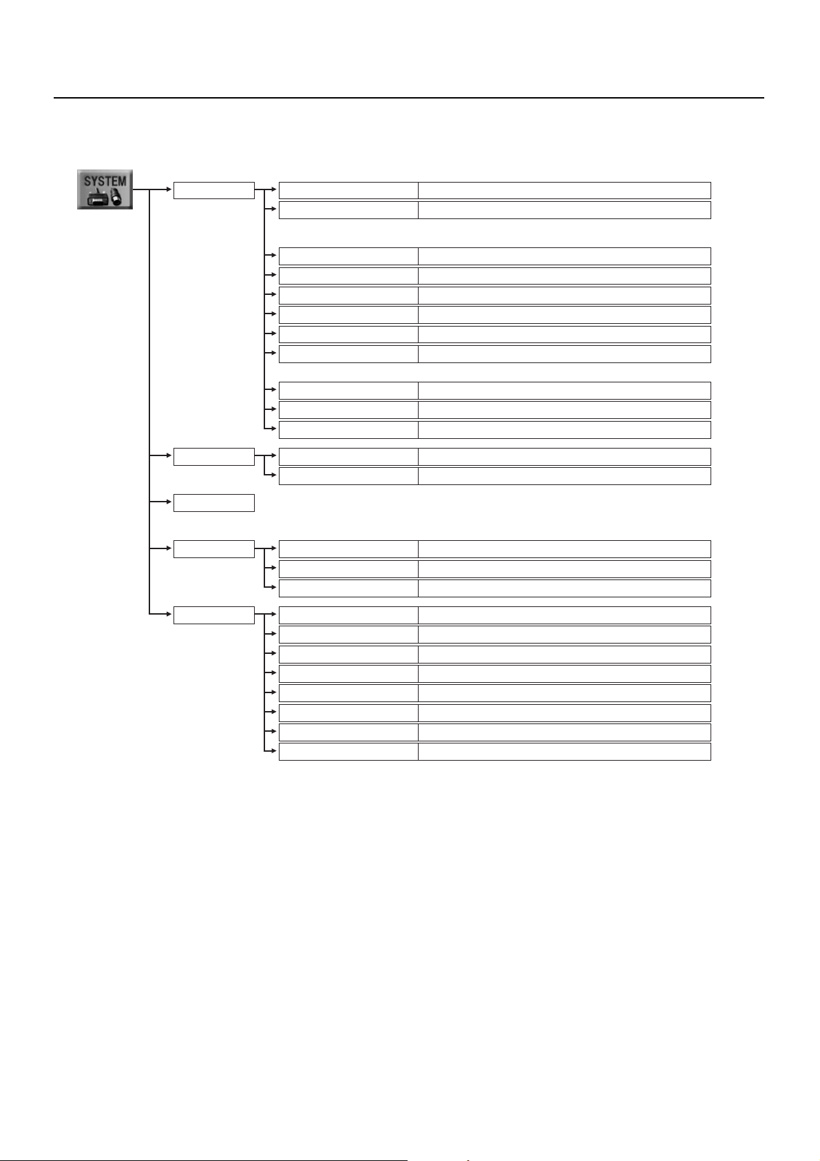
SYSTEM Menu
Here you make various system settings for the VR-3.
fig.system-menu.eps
Menu Operations and Menu List
PC IN
AUDIO DELAY
MIDI
MEMORY
H.POSITION
V.POSITION
* The maximum location values differ depending on the size values.
Be aware that location values will return to [0] if you change size values after adjusting the location values.
H.SIZE
V.SIZE
CONTRAST
BRIGHTNESS
SHARPNESS
FLICK FILTER
* It takes about a second to reflect changes in FLICK FILTER value.
COLOR
INPUT RESOLUTION
CH4 INPUT SOURCE
ANALOG OUT DELAY
USB OUT DELAY
This adjusts the horizontal location of computer input.
This adjusts the vertical location of computer input.
This adjusts the horizontal size of computer input.
This adjusts the vertical size of computer input.
This adjusts the contrast of computer input.
This adjusts the brightness of computer input.
This adjusts the sharpness of outlines in computer input.
This adjusts the degree of flicker reduction.
This adjusts the color of computer input.
This sets the input resolution. AUTO enables automatic determination.
This sets the source for channel 4.
This sets the amount of audio delay for analog output.
This sets the amount of audio delay for USB output.
* For information about MIDI settings, download the separate reference materials for remote
control from the following Roland website.
http://www.rolandsystemsgroup.net/
SAVE SETTING
LOAD SETTING
POWER ON LOAD
This selects the number of the destination for saving.
This selects the number to load.
Setting this to ON loads settings at startup.
SETUP
NTSC/PAL
LCD BRIGHTNESS
MENU DISPLAY LEVEL
BCKGND LEV - OVERLAY
USB VIDEO FILTER
This switches between NTSC and PAL.
This adjusts the brightness of the LCD screen.
This adjusts the brightness of the menu display.
This adjusts the brightness of the background (4 split) in overlay mode.
Setting this to ON makes for smooth display of USB-output video.
AUTO OFF Setting this to OFF deactivates the AUTO OFF feature.
FACTORY RESET
VERSION
This returns the VR-3 to its factory-default state.
This displays the version number of the system software.
47
Page 48

Appendices
Main Specifications
fig.spec-sheet_E.eps
Video Processing
Format
Video
PC-RGB
Sampling
Frame Synchronizer
NTSC/PAL (ITU601)
800 x 600/120 Hz, 832 x 624/75 Hz,
1024 x 768/80 Hz,1152 x 864/75 Hz,
1152 x 870/75 Hz,1280 x 720/60 Hz,
1280 x 768/75 Hz, 1280 x 800/75 Hz,
1280 x 1024/75 Hz, 1366 x 768 /75 Hz
(RGB VH : Positive Logic/Negative Logic)
* Conforms to VESA DMT Ver 1.0 Revision 10
* The refresh rate is the maximum value of each resolution.
13.5 MHz, 4:2:2 (Y:R-Y:B-Y), 8 bits
Built-in x 4
Audio Processing
Sampling 24 bits / 48 kHz
Input Connectors
Video
Audio
PC-RGB
Composite (RCA pin type) x 4
XLR/TRS combo type x 4
RCA pin type x 1 pair (L/R)
Stereo mini type x 1
Built-in stereo mic x 1 pair (L/R)
HD DB-15 type x 1
* If video is simultaneously input to Ch 4, PC-RGB takes priority.
Output Connectors
Video
Audio
Final Out
Preview
Final Out
PHONES
Composite (RCA pin type) x 2
Composite (RCA pin type) x 1
Standard type x 1 pair (L/R)
RCA pin type x 1 pair (L/R)
Standard type x 1, Stereo mini type x 1
PC-RGB (Thru out) HD DB-15 type x 1
Other Connectors
Remote Control
USB
MIDI IN (5 pin DIN type) x 1
MIDI OUT/THRU (5 pin DIN type) x 1
B type x 1
* Supports USB 2.0 Hi-Speed
In the interest of product improvement, the specifications and/or appearance of this unit are subject to change without prior notice.
Input Level and Impadance
Video
PC-RGB
Audio Input
Impedance
Audio
Input
Level
XLR/TRS
1.0 Vp-p, 75 ohms
0.7 Vp-p, 75 ohms (H, V:5VTTL)
XLR/TRS : 4 k ohms
RCA/PC INPUT : 15 k ohms
- 68 to + 4 dBu
Max Input Level : + 22 dBu
-10 dBu, Max Input Level : + 8 dBuRCA
-15dBu, Max Input Level : + 3 dBuPC INPUT
Output Level and Impadance
Video
Audio Output
Impedance
Audio
Output
Level
Final Out
1.0 Vp-p, 75 ohms
Final Out : 1 k ohms
PHONES : 10 ohms
- 10 dBu, Max Output Level : + 8 dBu
25mW + 25mWPHONES
Effects
Video
Audio
Transition
Composition
Input
Output
Cut, Mix, Wipe
Luminance Key, Chroma Key,
Picture in Picture, Split
High Pass, Noise Gate, EQ (Hi/Lo)
Noise Suppressor, Enhancer,
Master (Hi/Lo), Audio Delay,
Reverb
Others
Display
Power Supply
Current Draw
Dimensions
Weight (excl. AC adaptor)
Accesories
320 x 240 dotes
TFT color touch screen
DC 9 V (AC adaptor)
1.5 A
302 (W) x 208 (D) x 75 (H) mm
11-15/16 (W) x 8-3/16 (D) x 3 (H) inches
2.0 kg / 4 lbs 7 oz
AC adaptor and power cord,
USB cable (A type - B type) x 1,
Owner's manual
About Remote Control
The VR-3 can be operated remotely from an external MIDI device. For more information about remote control, download the
separately available reference document from the following Roland website.
http://www.roland.co.jp/solution/
fig.MVC-logo.eps
The VR-3 can be operated remotely from a device that supports MIDI Visual Control. MIDI Visual Control is a feature that uses MIDI
to link visual expression to a musical performance.
48
Page 49

Troubleshooting
No picture is output from the projector.
Is the [OUTPUT FADE] dial centered?
A fade is applied to output if the dial is turned either clockwise or counterclockwise. When performing output, adjust the dial to
center. The indicator above the dial lights up when the dial is at center. The indicator flashes when the dial has been turned either
clockwise or counterclockwise.
No microphone audio is output, even when the faders are raised.
Have the [GAIN] dials been turned to appropriate positions?
When input sensitivity has been lowered, no audio is output even when the faders are raised.
Is the connected microphone a condenser mic?
When you connect a condenser microphone that requires power supply, set the [PHANTOM] switch to ON.
Transition effects are not applied.
Is the length of time for transition effects (TRANSITION TIME) set at zero?
When the time is set at zero, no transition effects are applied even when [MIX] or [WIPE] is selected.
Appendices
A logo cannot be input from a computer.
Is the RGB output from the computer at a resolution supported by the VR-3?
RGB signals at a resolution that the VR-3 does not support cannot be input correctly. For supported resolutions, check “Main
Specifications.”
When you connect the computer, did you connect to the [PC IN] connector, not to [THRU] connector?
The [THRU] connector is for passing output through.
Video from the computer is corrupted.
When a rapidly moving video is input from a computer, flicker or other picture corruption may occur. This is called “tearing,” and
does not indicate an equipment malfunction.
Compositing a logo is not possible.
Is the extraction color set correctly? Alternatively, was the [KEY LEVEL] dial turned in the wrong direction?
By default, black is extracted for luminance keying. If the background is a different color, then correct extraction is not possible.
Correct extraction is also impossible when the [KEY LEVEL] dial has been turned in the wrong direction.
No reverb is applied when the dial is turned.
Is [REVERB SW] at the AUDIO menu set to [OFF]?
When this is set to OFF, no reverb is applied when the dial is turned. Also, when the reverb send amount on the input channel is
too low, it can be difficult to discern the reverb.
49
Page 50

Appendices
Dimensions
fig.dimension.eps
Unit : mm
80.3
66.6
303
202.7
50.2
50
Page 51

Memo
51
Page 52

Memo
52
Page 53

Index
A
Ambient Sound ............................................................................. 26
amplifier .......................................................................................... 21
Audio Mixer ............................................................................. 10, 19
AUTO OFF .......................................................................................... 9
C
CHR KEY ........................................................................................... 13
Chroma key .................................................................................... 36
COMPOSITION ........................................................................ 13, 29
cord hook ........................................................................................... 8
E
EQ ....................................................................................................... 11
F
fade ................................................................................................... 24
Faders ............................................................................................... 11
FREEZE ....................................................................................... 12, 24
G
GAIN ........................................................................................... 11, 25
H
headphones ................................................................................... 15
I
inset screen .................................................................................... 31
Internal mic .................................................................................... 10
K
KEY ....................................................................................... 13, 34, 36
KEY LEVEL ........................................................................................ 13
L
Level Meter ..................................................................................... 11
LUMI KEY ......................................................................................... 13
Luminance key .............................................................................. 34
P
PAL ..................................................................................................... 43
PAN ............................................................................................. 11, 26
PHANTOM ....................................................................................... 15
PHONES ..................................................................................... 11, 15
Picture-in-Picture .......................................................................... 29
PinP ............................................................................................. 13, 29
PREVIEW ........................................................................................... 21
projectors ........................................................................................ 21
R
REVERB ............................................................................................. 28
reverb ................................................................................................ 11
S
scan converter ............................................................................... 20
Sensitivity ........................................................................................ 25
sources ............................................................................................. 18
speakers ........................................................................................... 21
SPLIT .................................................................................................. 13
split .................................................................................................... 32
T
Touch Panel .................................................................................... 22
TRANSITION .................................................................................... 12
transition effect ............................................................................. 22
U
USB Port ........................................................................................... 14
USB port ........................................................................................... 38
V
VALUE ............................................................................................... 12
VIDEO SELECT ......................................................................... 12, 23
Video Select .................................................................................... 10
view mode ...................................................................................... 12
Volume Balance ............................................................................ 27
M
MASTER ............................................................................................ 11
MENU ................................................................................................ 12
Microphones .................................................................................. 19
MONITOR ........................................................................................ 12
N
NTSC .................................................................................................. 43
O
Operating Systems ...................................................................... 38
OUTPUT FADE ............................................................................... 12
overlay .............................................................................................. 41
53
Page 54

For EU Countries
This product complies with the requirements of EMC Directive 2004/108/EC.
For the USA
FEDERAL COMMUNICATIONS COMMISSION
RADIO FREQUENCY INTERFERENCE STATEMENT
This equipment has been tested and found to comply with the limits for a Class B digital device, pursuant to Part 15 of the
FCC Rules. These limits are designed to provide reasonable protectio n against harmful interferenc e in a residentia l
installation. This equipment generates, uses, and can radiate radio frequency energy and, if not installed and used in
accordance with the instructions, may cause harmful interference to radio communications. However, there is no guarantee
that interference will not occur in a particular installation. If this equipment does cause harmful interference to radio or
television reception, which can be determined by turning the equipment off and on, the user is encouraged to try to correct the
interference by one or more of the following measures:
— Reorient or relocate the receiving antenna.
— Increase the separation between the equipment and receiver.
— Connect the equipment into an outlet on a circuit different from that to which the receiver is connected.
— Consult the dealer or an experienced radio/TV technician for help.
This device complies with Part 15 of the FCC Rules. Operation is subject to the following two conditions:
(1) this device may not cause harmful interference, and
(2) this device must accept any interference received, including interference that may cause undesired operation.
This equipment requires shielded interface cables in order to meet FCC class B limit.
Any unauthorized changes or modifications not expressly approved by the party responsible for compliance could void the user s
authority to operate the equipment.
For Canada
NOTICE
This Class B digital apparatus meets all requirements of the Canadian Interference-Causing Equipment Regulations.
AVIS
Cet appareil num rique de la classe B respecte toutes les exigences du R glement sur le mat riel brouilleur du Canada.
For C.A. US (Proposition 65
WARNING
This product contains chemicals known to cause cancer, birth defects and other reproductive harm, including lead.
For EU Countries
)
Page 55

VR-3
AV MIXER
For China
Page 56

*5100023675-01*
 Loading...