

Page 1
QUICK START
Thank you, and congratulations on your choice of the Roland
Console
.
The documentation for the VM-7000 Series consists of the volumes as listed below.If you are
using the VM-7000 for the first time, we recommend you to first start with the “Quick Start” (this
volume) when using this system, to get a thorough grasp of its operation performance ability. The
details to the use for every function can be found in the Console (C7200/C7100) section of the
“Owner’s Manual”. Look up the function you are searching for on the index and read the chapter
carefully.
For The Console
•
Quick Start (this volume):
•
VM-C7200/C7100 Owner’s Manual:
Parameter List, MIDI Implementation, etc.
•
VM-C7200/C7100 Libraries:
library
For The Processor
•
VM-7200/7100 Owner’s Manual:
devices, etc.
•
VM-7000 SERIES Block Diagram:
* adat® is a registered trademark of ALESIS Corporation.
* TASCAM® is a registered trademark of TEAC Corporation.
* All product names mentioned in this document are trademarks or registered trademarks of their
respective owners.
fig.0-03
Easy instructions for basic steps of operations.
Detailed instructions for each function, glossary, Q&As,
Internal connections templates, list of EQ and effects preset
Instructions for using the Processor, how to install optional
Block diagram of the whole system
VM-C7200 (VM-C7100) V-Mixing
Copyright © 1999 ROLAND CORPORATION
All rights reserved. No part of this publication may be reproduced in any form without the
written permission of ROLAND CORPORATION.
Roland Website
Roland US Website
http://www.roland.co.jp/
http://www.rolandus.com/
Page 2

Table of Contents
Getting Started........................................................................................4
How to Use The QUICK START...............................................................................................................4
Installing the VM-C7100/C7200 Digital Mixing System.......................................................................5
Connections..................................................................................................................................................7
Turning On the Power..............................................................................................................................10
To Adjust the Brightness of the Display................................................................................................12
If You’re Confused About What’s Being Displayed or What’s Going On .......................................12
Restoring the Original Factory Settings.................................................................................................13
Setting the Internal Clock.........................................................................................................................14
Preparing a Memory Card.......................................................................................................................16
To Format a Memory Card...........................................................................................................16
To Create a New Project ...............................................................................................................19
Turning Off the Power .............................................................................................................................20
Before Mixing Operations....................................................................22
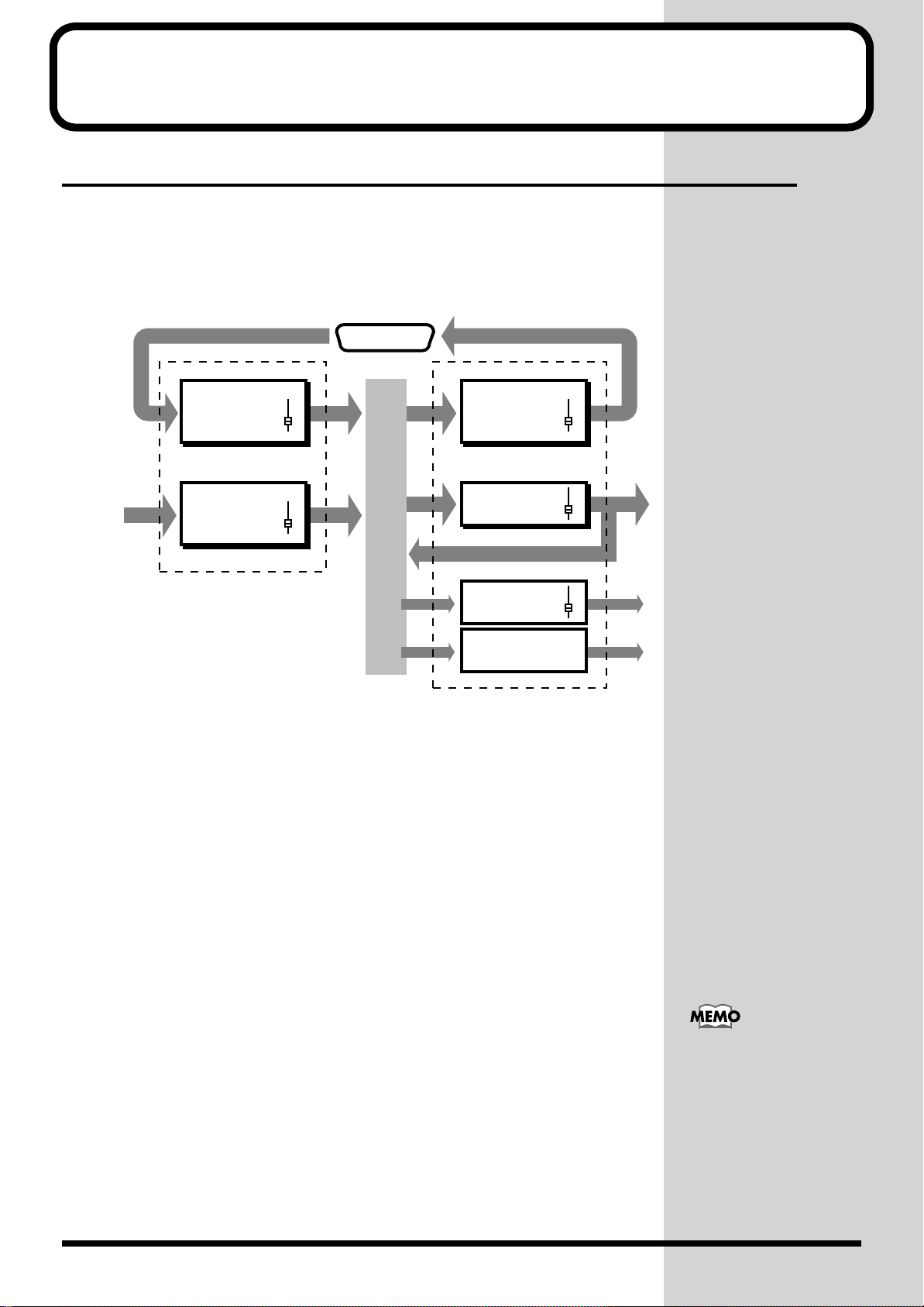
Internal Signal Flow..................................................................................................................................22
1. Input Channels...........................................................................................................................22
2. Busses / Output Routes............................................................................................................23
How to Operate This System...................................................................................................................24
The Display (example)..................................................................................................................24
To Change Parameters..................................................................................................................25
Mixing Operations.................................................................................26
Setting the Input Gain ..............................................................................................................................26
Setting the Channel Levels and L/R Pans.............................................................................................28
Setting the Master Level and Master Stereo Balance...........................................................................30
Adjusting a Signal’s Tone (Equalizer)....................................................................................................32
Setting Up a Monitor................................................................................................................................34
Coupling Adjacent Channels ..................................................................................................................36
Muting a Channel .....................................................................................................................................38
Storing a Project.........................................................................................................................................39
Using Sub Outputs ...............................................................................40
Setting Up Monitor Sends for Studio or Stage......................................................................................40
To Select Signals for Studio Monitors.........................................................................................40
To Talk to Someone on a Stage or out in a Studio (Talkback).................................................42
Flex Bus.......................................................................................................................................................43
Flex Bus Output (MULTI OUT/ASSIGNABLE OUT).............................................................44
Flex Bus Output (Internal)............................................................................................................46
Sending Signals to a Flex Bus..................................................................................................................48
Using On-Board Effects .......................................................................50
Send-Return Loop Effect..........................................................................................................................51
Setting the Onboard Effect Position and Value....................................................................................54
Selecting the Effects ..................................................................................................................................58
Using a Channel’s Feedback Delay (Channel Delay) ..........................................................................60
Other Important Features.....................................................................62
Storing a Mixing State (Scene).................................................................................................................62
To Store a Scene .............................................................................................................................62
To Recall a Scene............................................................................................................................64
Setting Signal Routings on the Display (Virtual Patchbay)................................................................66
Simultaneously Adjusting the Levels of Multiple Channels..............................................................68
To Create a Group of Channel Faders (Fader Group Master) ................................................68
To Mute a Group of Multiple Channels (Mute Group) ...........................................................70
2
Page 3

Table of Contents
Some Special Features.........................................................................72
The Spectrum Analyzer...........................................................................................................................72
5.1 Surround..............................................................................................................................................73
Speaker Modeling..................................................................................................................................... 74
Using EZ Routing Templates...............................................................75
8 Track MDM With MIDI Sound Module Recording .........................................................................76
Live Jazz Ensemble With 8 Track Digital Recording .......................................................................... 82
Advanced Operations – 8 Track Analog Recording ................................................................86
Connection Samples ............................................................................88
Connection Samples Using the TASCAM DA Series.......................................................................... 88
48 Track Recording System (TASCAM DA-88 x 6)..................................................................88
48 Track Recording System (TASCAM DA-88 x 6 + RC-848)................................................. 89
24 Track Recording System (TASCAM DA-88 x 3)..................................................................90
8 Track Recording System (TASCAM DA-88 x 1)....................................................................91
Connection Samples Using the Alesis ADAT Series...........................................................................92
48 Track Recording System (Alesis ADAT x 6) ........................................................................92
48 Track Recording System (Alesis ADAT x 6 and BRC)........................................................93
24 Track Recording System (Alesis ADAT x 3) ........................................................................94
48 Track Recording System (Alesis ADAT x 1) ........................................................................95
Connection Sample Using Digidesign Protools...................................................................................96
3
Page 4
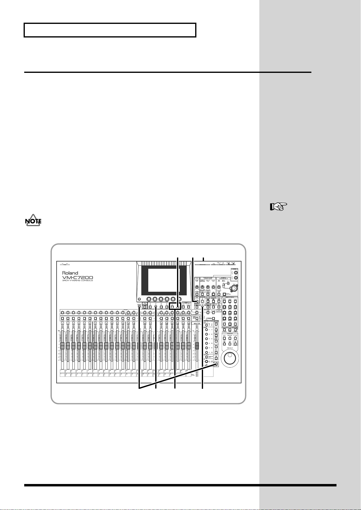
Getting Started
How to Use The QUICK START
The QUICK START basically explains the operations as follows:
Mixing Operations
Now let’s do some mixing. This chapter describes two-channel – stereo –
mixing of connected sources that will be sent out from the system through
its MAIN OUT jacks.
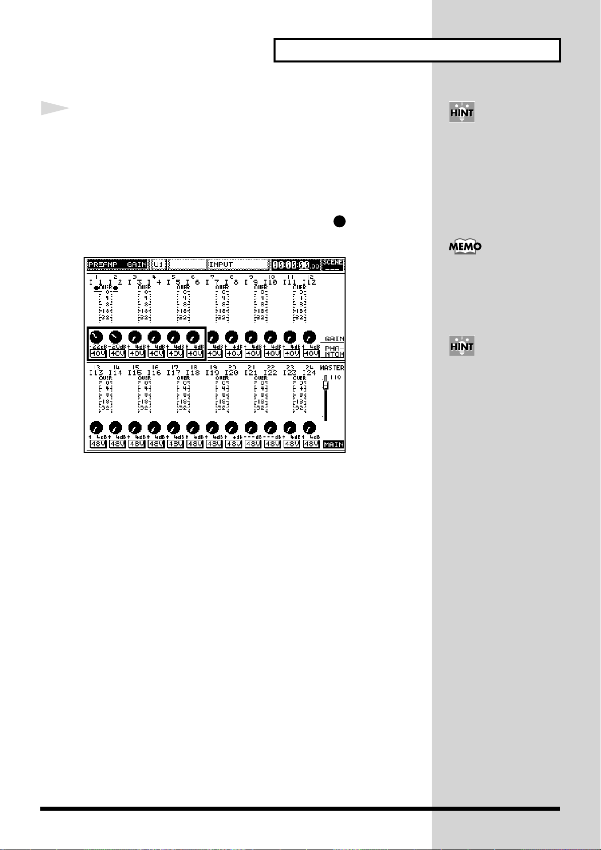
Setting the Input Gain
Let’s adjust the input gain levels of all of your connected instruments and so
on. (If you are working on digital connected sources, you do not have to
read this section.)
fig.107
2
1
Press [PREAMP GAIN].
[PREAMP GAIN] lights and the “PREAMP GAIN” display appears.
fig.206
Important notifications to
prevent considerable
damage to your
equipment.
Owner’s Manual “Gain,
Phantom Power Supply,
Phase and Attenuator”
(p.68)
Reference page for
detailed information to
this section.
As preset at the factory, all
channel numbers on the
console correspond to the
input numbers on the
processor. You may,
however, change the
channels’ connections or
work on multiple channels
at once (Owner’s Manual
“Selecting an input
channel’s signal source”
p.67).
Other convenient
setup operations.
1
If you selected DIGITAL IN
A/B as your source input,
these steps will not be
necessary.
Additional suppllemental
remarks.
4
Keys or knobs used in
the corresponding Step
number.
You can also set the gain
level with the cursor and
knobs on the display.
26
The display mainly used
during the operation.
Step number in the setup procedure.
• For further information to operations or functions, read your console’s and processor’s
Owner’s Manuals.
Page 5

Installing the VM-C7100/C7200 Digital Mixing System
Getting Started
The VM-C7100/C7200 Digital Mixing System consists of two units
–
the
mixing console and the mixing processor.
About the VM-C7100/C7200 Digital Mixing System
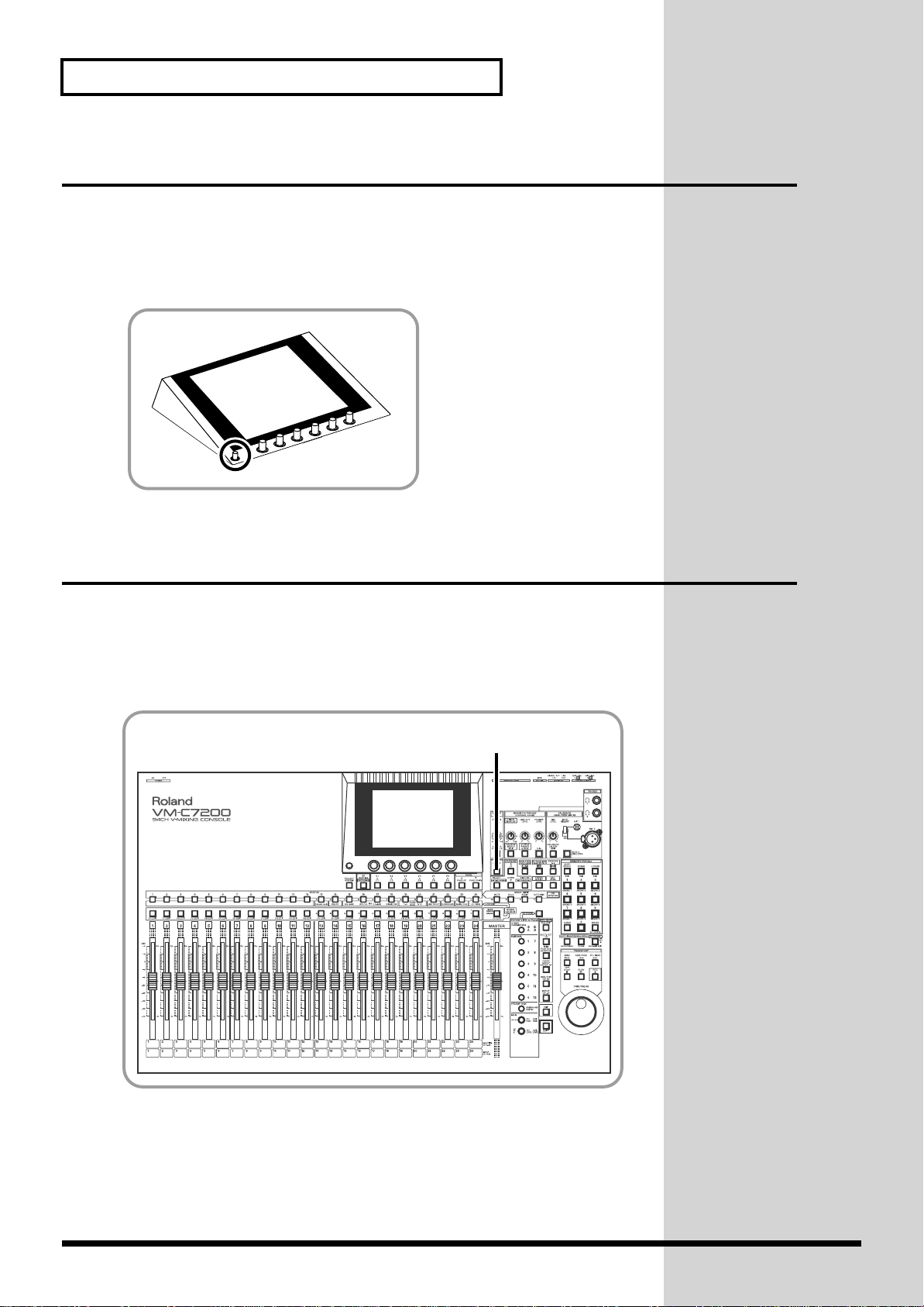
The Mixing Console
fig.001
All mixing activities take place on the mixing console, including the
adjusting of faders, the assignment of signals to busses and the application
of effects.
Place the console in an area such as a control room. Then, connect your
monitors, audio equipment, stereo mastering recorders and headphones to
the corresponding jacks on the console.
Owner’s Manual “Names
of Things and What They
Do” (p.11)
You may attach an optional
wooden panel and a level
meter bridge (sold
separately) to the console.
The Mixing Processor
fig.002
The mixing processor supplies the majority of the system’s input and output
jacks.
Place the processor at a convenient location near your performers, such as
in a studio or on a stage. Next, connect instruments, microphones,
amplifiers, multi-track recorders, effects processors, and monitors for the
performers to the corresponding mixing processor jacks.
OWNER’S MANUAL for
the Processor
Up to 2 processors can be
connected to each console,
which enables you to
achieve 94 input channels
(Owner’s Manual “Settings
related to cascade
connection” p.41,
OWNER’S MANUAL for
the Processor “Connecting
Two Processors (Cascade
Connection)” p.32 ).
5
Page 6
Getting Started
To Connect the VM-C7100/C7200 Digital Mixing System
Use a pair of AES/EBU digital audio cables to connect the mixing console and mixing processor. These
cables are supplied as a set with the mixing console.
fig.003
Use the supplied pair of
AES/EBU Digital Audio Cables.
6
Page 7
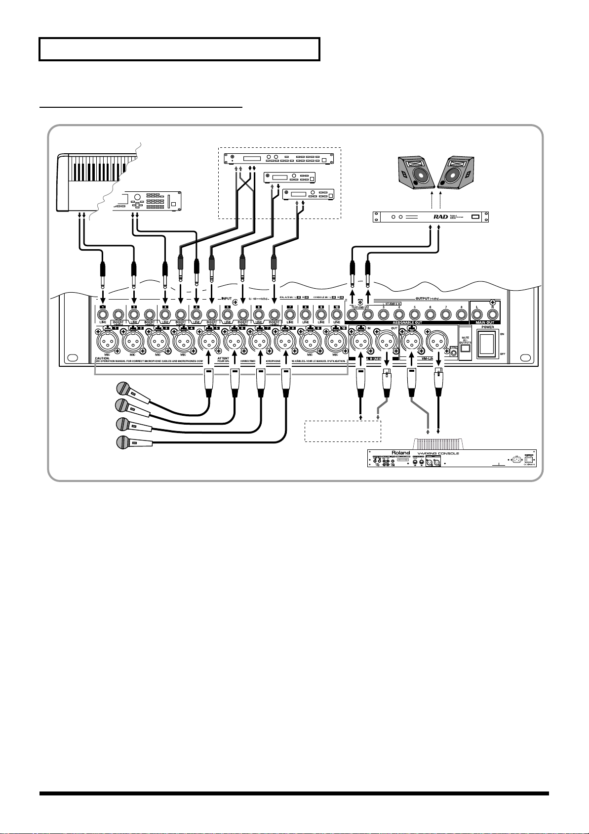
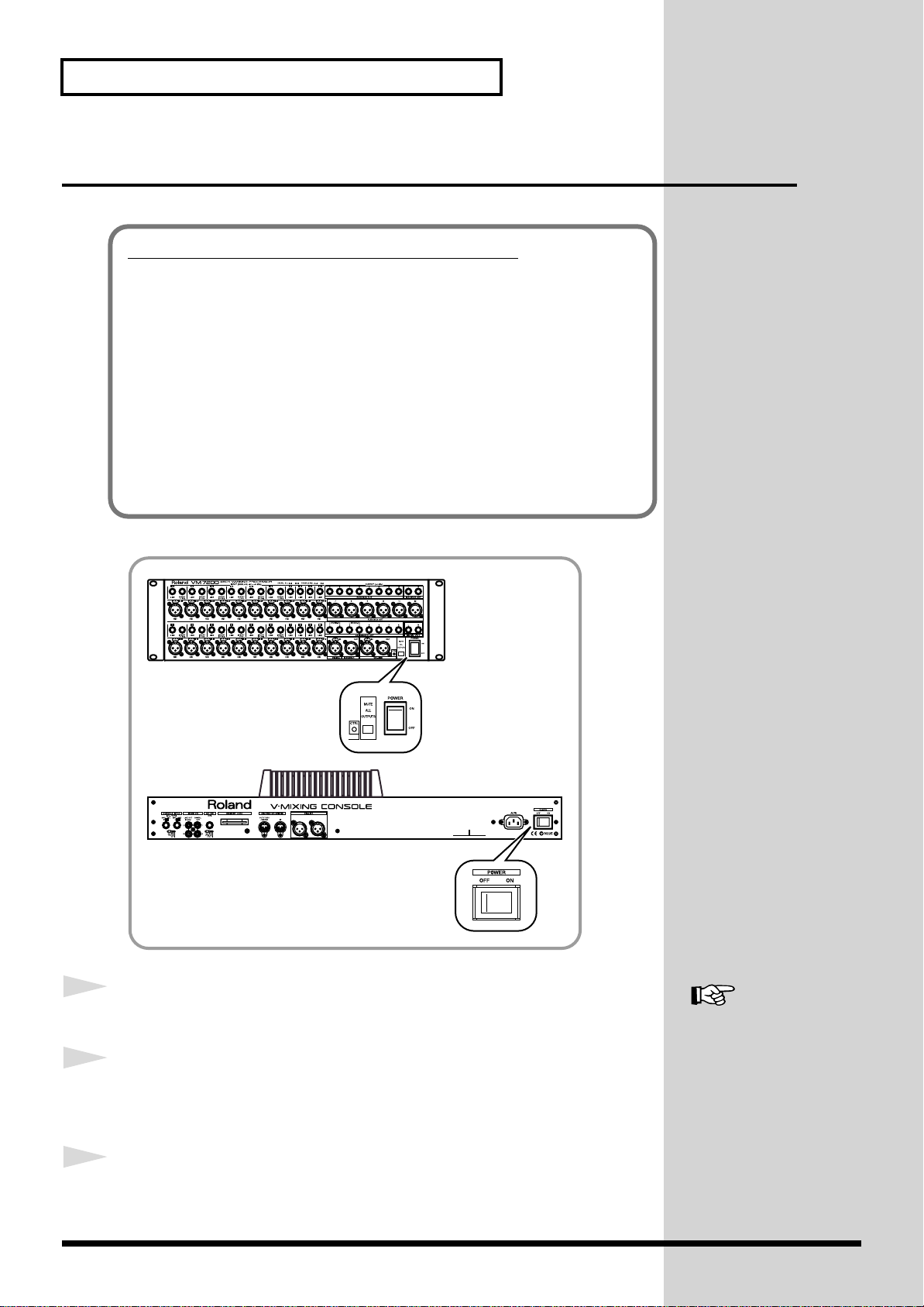
Connections
To avoid problems and/or damage to speakers or other devices, always turn down the
volume and turn off the power on all devices before making any connections.
Basic Connections
Rear Panel of the Mixing Console
fig.004
Getting Started
Microphone, Sub Mixer,
MD/CD Player
Mixing Processor
Monitor in the
Control Room
Speaker
Amp
Digital
Powered
Speaker
(Roland DS-90 etc.)
AC Power Supply
7
Page 8
Getting Started
Front Panel of the Mixing Processor
fig.005
123
Microphone
Synthesizer,
Sound Module, etc
345 6
4
Channel Insert (Effects Processor)
5678
Branch Cable
(e.g. PCS-31)
Digital
Audio
Input/Output
AES/EBU Jack
on Pro Audio Device
Monitor Speaker
Monitor Amp,
Headphone Amp
for Players
Mixing Console
8
Page 9
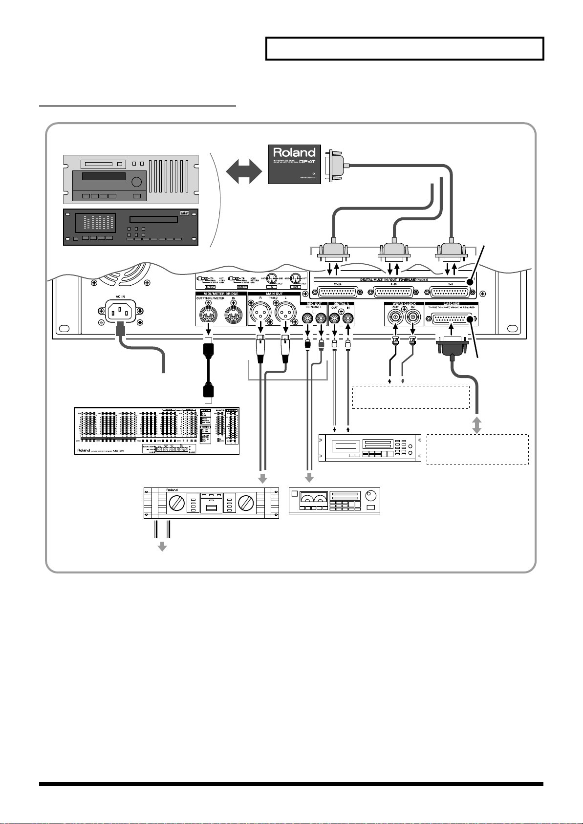
Rear Panel of the Mixing Processor
fig.006
Digital Multi-track Tape Recorder
(TASCAM/ADAT)
Getting Started
8 ch
AC Power Supply
MB-24 (Option)
Main
Output
Roland DIF-AT
(Interface Box)
R-BUS
Cable
Word Clock Connector on
Digital Recorder or similar device
Digital Input/Output
DAT/MD Recorder, etc.
Analog Input
To R-BUS Compatible
Device
VM-24E
(Option)
VM-24C
(Option)
Cable supplied
with the
VM-24C
Mixing Processor to be
connected in cascade
(VM-7200/7100)
Power Amp
PA Speaker
Tape Recorder,
MD Recorder, etc.
If you wish to connect the VM-C7100/C7200 to ADAT or TASCAM digital multi-track tape recorders, you
must first install an optional VM-24E, sold separately (OWNER’S MANUAL for the Processor “Installing RBUS (RMDB2) Connectors (VM-24E)” p.14).
9
Page 10
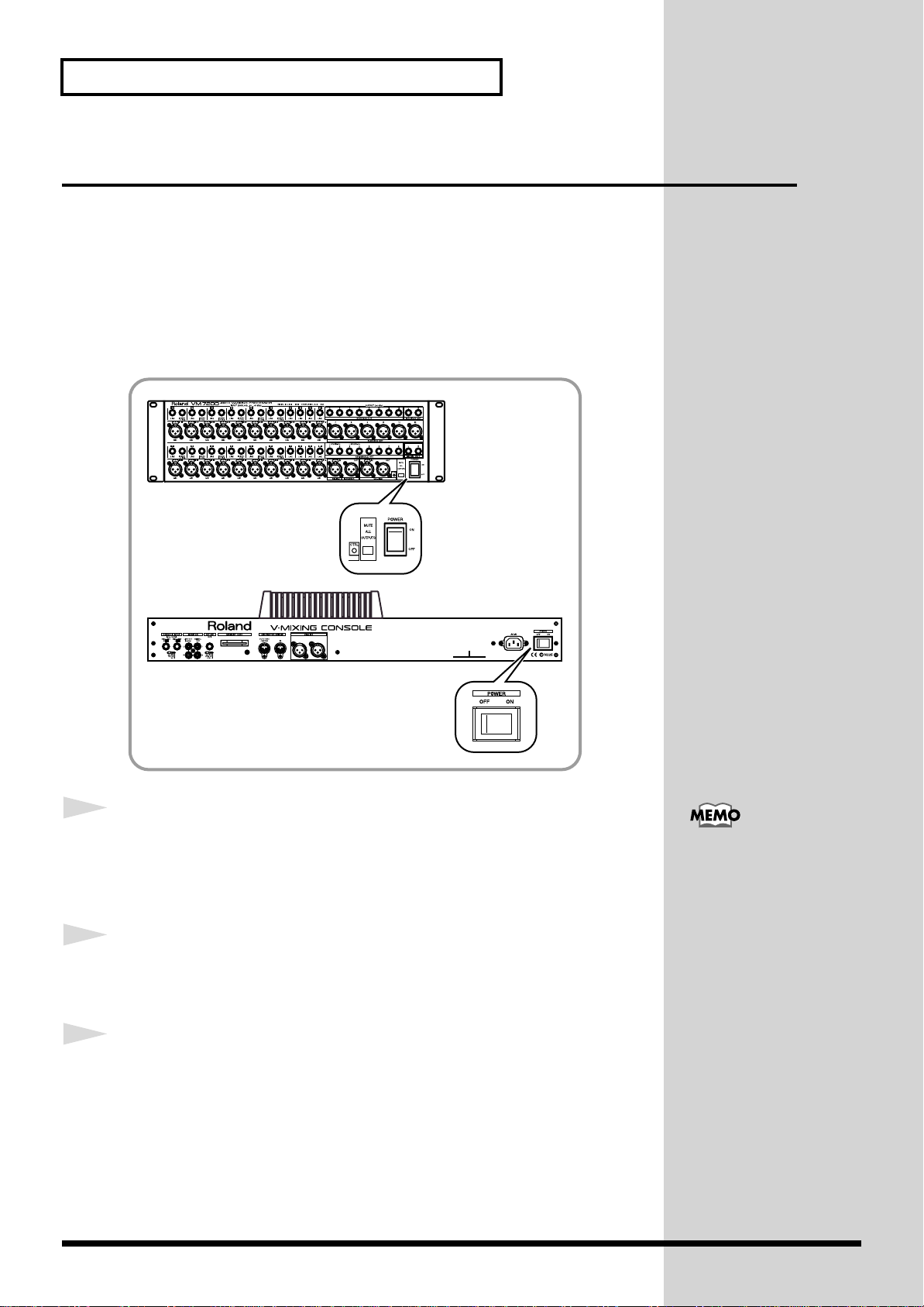
Getting Started
Turning On the Power
After you have finished making connections (QUICK START: p.7), be sure
to turn on all of your devices in the proper order, as described in the
instructions below. Powering up in the wrong order may cause
malfunctions and/or damage to speakers and the devices.
Always make sure that each device’s volume level is turned down before
turning on its power. You may hear a slight noise even with the volume
turned down – this is normal, however, and does not indicate a malfunction.
fig.007
1
2
3
10
Turn on the power of any connected digital multi-track tape
recorder.
It takes a while for the device to startup.
Turn on the power of any additional connected digital devices
(DAT, MD recorder, hard disc recorder, etc.).
Turn on the power of any connected analog devices
(instruments, sound modules, effects processors, microphones,
CD players, MD players, tape recorders, etc.).
If an external device is to be
the source of the system’s
Word Clock (Owner’s
Manual: p.31), turn on the
power of that device first.
Page 11
Getting Started
4
5
6
Set [POWER] to ON on the front panel of the mixing
processor.
The CTRL indicator blinks during startup. When startup is completed, the
indicator lights in green.
After the CTRL indicator on the processor has turned green,
set [POWER] to ON on the rear panel of the mixing console.
When the “Check SYSTEM CONFIGURATION” message
appears on the display, press [F2](START) to execute the startup procedure.
The “LEVEL METER” display appears.
fig.201
When connected in cascade
(Owner’s Manual
“Settings related to cascade
conection” p.41), turn on
the power of the Slave
processor (“2nd UNIT”)
first.
7
It takes a short while for the system to start up. When you turn on the power,
all connected external devices must be recognized by the system, and
certain data must be loaded.
Turn on the power of connected audio equipment (amplifiers
and speakers).
When you change settings on a digital connected device, a loud noise
may occur. Always turn down the volumes to all speaker outputs to
prevent serious damage to your equipment, before working on your
digital devices.
11
Page 12
Getting Started
To Adjust the Brightness of the Display
You may wish to adjust the brightness of the display immediately after
power-up, under unusual viewing conditions, or after the unit has been on
for an extended period of time. Adjust the brightness of the screen using the
[CONTRAST] knob on the left bottom of the display.
fig.008
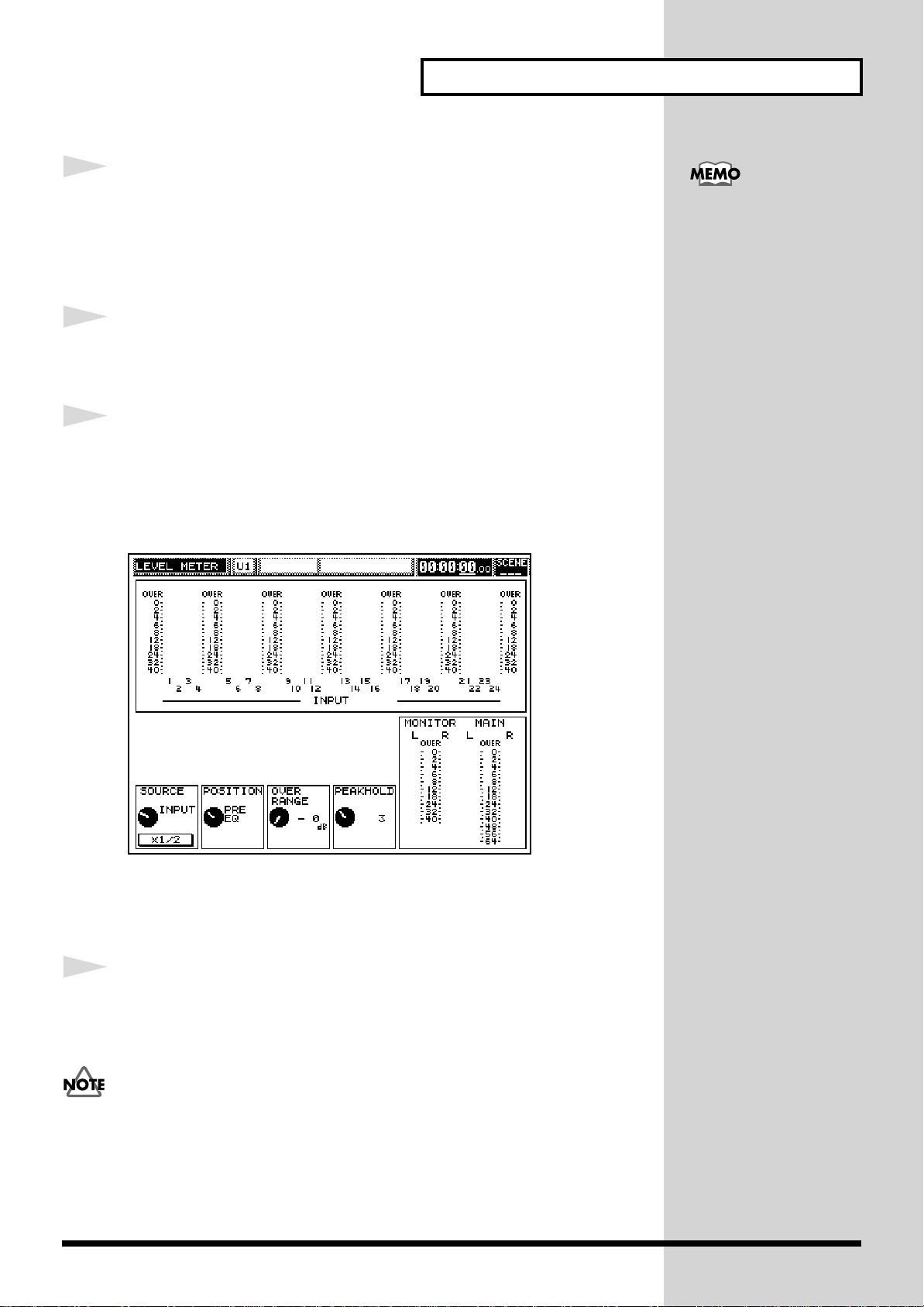
If You’re Confused About What’s Being Displayed or What’s Going On
If you become confused about what you’re seeing on the display, or have
lost your way during some procedure, press [LEVEL METER]. The display
returns to the screen shown immediately after power-up. You can try the
procedure you have been working on again from the beginning.
fig.201
LEVEL METER
12
If you find that your system functions differently than described in the
QUICK START or the Owner’s Manual, read “Troubleshooting” (Owner’s
Manual: p.261) for further information.
If the above steps do not resolve your problem, contact a nearby Roland
Service Center or an authorized Roland distributor, or the shop where you
made your purchase.
Page 13
Restoring the Original Factory Settings
You can restore the system’s parameters to their original default settings
using the following procedure.
• The Factory Reset function deletes all of your own settings.
• Be sure to turn off the power of all amplifiers and speakers before
executing Factory Reset.
fig.103
1,2 3
Getting Started
1
2
3
4
4
2
Turn off the power of the mixing console.
Hold down [PROJECT] and [F1] while turning on the console’s
power.
When the “FACTORY RESET” display appears, press
[F1](OK).
To cancel, press [F6](Cancel).
It takes a while to reset the system.
Press [F2](START) to startup the system.
The “LEVEL METER” display appears.
13
Page 14
Getting Started
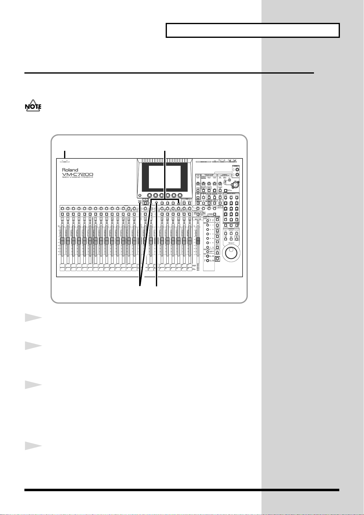
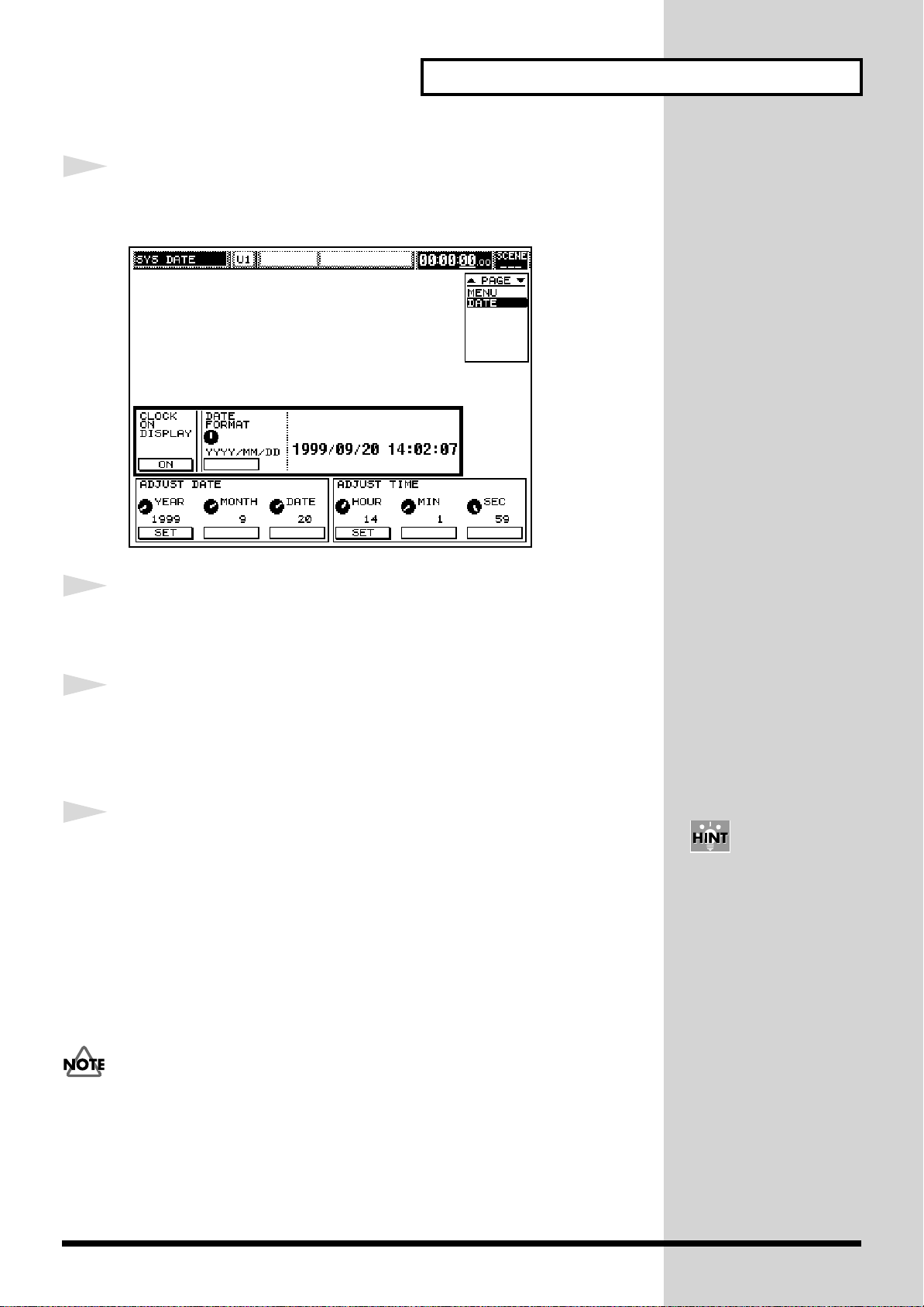
Setting the Internal Clock
The mixing console unit contains an internal clock. When you store a
Project, the current time, day, and month information is automatically
stamped into the Project (Time Stamp). This makes the management of
Projects easier, since you can sort them in day/time order. When you turn
on the power for the first time after purchase, be sure to set your system’s
date and time by following the instructions below.
fig.101
5672
1
2
15 63 4
Hold down [SHIFT] and press [PROJECT].
Press CURSOR [UP] to move the cursor to the upper field.
14
Page 15
Getting Started
3
4
Press [F5](DATE).
The “SYS DATE” display appears.
fig.202
Press CURSOR [DOWN] to move the cursor to the “ADJUST
5
6
DATE / ADJUST TIME” field.
Set the current date. Turn [V1](YEAR), [V2](MONTH),
[V3](DATE) to select the current date, and then press [F1](SET)
to confirm your selection.
Set the current time. Turn [V4](HOUR), [V5](MIN), [V6](SEC)
to select the current time, and then press [F4](SET) to confirm.
The time you set becomes effective immediately.
The date and time are set.
• To return to the original display (the “LEVEL METER” display),
press [LEVEL METER].
The console contains a lithium battery that allows the system to retain
the internal clock settings and certain other parameter values. When
the battery becomes weak, malfunctions may occur – the system clock
may not function correctly, or the unit may not properly recall your last
settings at power-up. If such things occur, restart the mixing console.
If a message indicating low battery power appears, change the battery
(Owner’s Manual “How to replace the battery” p.26), and restore the
original factory settings (QUICK START: p.13).
You can set the time on/off
on the display, and select
from various date display
formats (
“Adjusting internal clock”
p.25).
Owner’s Manual
15
Page 16
Getting Started
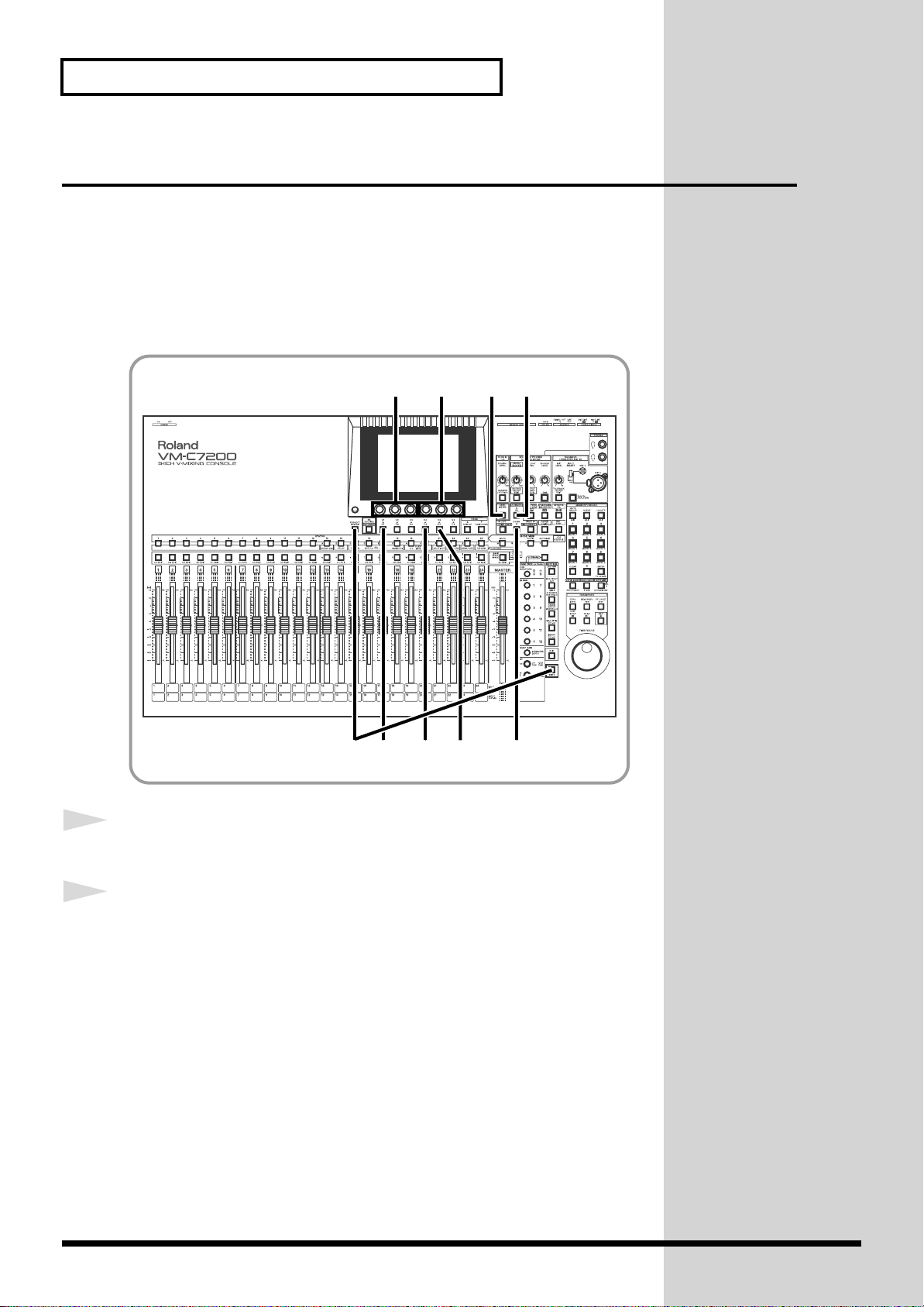
Preparing a Memory Card
You can store your current mixing settings on your console as a Project onto
a memory card (SmartMedia). A Project is a group of parameter settings that
the system memorizes. Such settings include Scenes (Owner’s Manual:
p.244) and Automix data (Owner’s Manual: p.232). You can instantly store/
recover these settings at any time by overwriting/reloading the Project.
We recommend you always create a new Project at the beginning of a new
mixing/recording session or live performance.
If a card is new, or if it has been used in another device, it must be formatted
for use in the system. If you already have a formatted the memory card,
proceed to “To Create a New Project” (p.19).
To Format a Memory Card
During formatting, all data on the card is erased. Therefore, be sure that the
card you intend to format does not contain data you wish to preserve
fig.102
4,8
19
.
Owner’s Manual “Storing
and Recalling All Mixer
Settings (Project)” (p.50)
16
25
6,7
3
Page 17
Getting Started
1
2
Insert the memory card into the mixing console.
Insert the memory card with the golden terminal strip upside.
fig.009
Hold down [SHIFT] and press [PROJECT].
3
4
Press CURSOR [DOWN] to move the cursor to the lower field.
Press [F6](MEMORY CARD).
The “SYS M.CARD” display with the card information appears.
fig.203
5
Press [F2](FORMAT).
The “CONFIRM / Format Card, OK?” message appears on the display.
17
Page 18

Getting Started
6
7
8
Press [F5](OK).
To cancel, press [F6](CANCEL).
When the “CONFIRM / Really Sure?” message appears, press
[F5](OK) again.
To cancel, press [F6](CANCEL).
After the formatting is finished, the “MESSAGE / Completed” message
appears on the display.
Press [F6](EXIT).
• To return to the original display (the “LEVEL METER” display),
press [LEVEL METER].
18
Page 19
To Create a New Project
fig.10
6
Getting Started
Owner’s Manual “Storing
and Recalling All Mixer
Setings (Project)” p.50
1
2
3
4
5
6
1 3,4
Press [PROJECT].
The “PROJECT” display appears.
Press CURSOR [DOWN] to move the cursor to the lower field.
Press [F2](NEW).
The “CREATE NEW PROJECT” message appears on the display.
Press [F2](CREATE).
The “CONFIRM / Create New Project, OK ?” message appears.
Press [F5](OK).
The “CONFIRM / Keep Current Mixer Setting ?” message appears.
Press [F4](YES) or [F5](NO).
• [F4]...The current settings are kept after a new Project is created.
5
27
You can name a Project by
pressing [F3](NAME/
PROJECT) in Step 3
(Owner’s Manual “Renaming/erase-protecting a
project” p.53).
7
• [F5]...The system will restore the original factory settings after a new
Project is created.
When the “MESSAGE / Completed” display appears, press
[F6](EXIT).
A new Project has been created.
19
Page 20
Getting Started
Turning Off the Power
Points to check before turning the power off
• Have you stored your Automix data on a memory card?
Your current Automix data is stored in the console’s temporary memory
– this memory is cleared when you turn off the power. Be sure to save any
Automix data you wish to preserve onto a card before powering down.
• Did you turn down the volumes of the mixing console and
connected audio equipment?
If you leave the volume levels of your equipment turned up when you
turn off the power, a loud noise may occur that can cause damage to your
equipment.
fig.007
1
2
3
20
Store the current settings onto a memory card.
QUICK START “Storing a
Project” (p.39)
Turn off the power of connected audio equipment (amplifiers
and speakers).
Set [POWER] to OFF on the rear panel of the mixing console.
Page 21

Getting Started
4
5
6
7
Set [POWER] to OFF on the front panel of the mixing
processor.
Turn off the power of connected analog devices (instruments,
sound modules, effects processors, microphones, CD players,
MD players, tape recorders, etc.).
Turn off the power of connected digital devices (DAT, MD
recorder, hard disc recorder, etc.).
Turn off the power of any connected digital multi-track tape
recorder.
21
Page 22
Before Mixing Operations
Internal Signal Flow
The diagram below provides an overview of the audio signal flow. For
details, refer to the “Block Diagram” attached to the processor (VM-7200/
7100).
fig.104
R-BUS
MULTI IN
1–24
INPUT
1–24
1
1. Input Channels
There are two input modes to this system – [INPUT] and [MULTI IN].
MULTI OUT
1–24
FLEX BUS MASTER
1–12
B
U
S
MAIN OUT
L/R
CUE OUT
L/R
2
INPUT...1-24
The following input jacks can be assigned to these channels:
• 20 analog input jacks on the VM-7200 mixing processor (10 on VM-
• Stereo digital input jacks on the mixing processor (A or B)
• 2 analog input jacks on the mixing console (stereo L/R).
MULTI IN...1-24
Multi-channel audio signals can be input from external equipment – such as
multi-track recorders – via these channels.
The correspondence between input signal channel numbers and Multi In
channels can be re-patched internally.
22
7100).
In order to use Multi In
channels, a VM-24E (sold
separately) must be
connected to the mixing
processor in order to add
an R-BUS connector I/O
terminal (OWNER’S
MANUAL for the
Processor: p.14).
Page 23

2. Busses / Output Routes
b
MULTI OUT
A multiple output channel to which signals from any input channel and/or
Flex Bus can be routed. Digital multi-track output to a digital multi-track
recorder can be performed by installing an optional VM-24E (sold
separately) in the system. You can also send analog track outputs from
ASSIGNABLE OUT jacks.
FLEX BUSSES 1-12
A Flex Bus is a multi-purpose bus through which signals can be sent to
another bus, to other internal destinations or to external devices. Flex Busses
are capable of sending signals from all input channels as well as Flex Busses
1-8. Any ASSIGNABLE OUT, DIGITAL OUTs A and B, and MULTI OUT
can be selected for outputting Flex Bus signals to external destinations. If
you are using a VM-7200 processor, dedicated output jacks are also
available for Flex Busses 5-12.
Before Mixing Operations
MAIN OUT
CUE OUT
Output of the overall stereo mix containing all desired channels, to be sent
to the master recorder or the main PA amplifier. Signals can be sent from all
input channels and Flex Busses.
In addition to the dedicated output terminals (MAIN OUT and REC OUT),
signals can be directed to any ASSIGNABLE OUT, DIGITAL OUTs A and B,
and/or any MULTI OUT.
Stereo bus used mainly for monitoring. Signals can be sent to the Cue bus
from all input channels and Flex Busses.
Cue signals can be output from MONITOR OUT and PHONES jacks to
external monitoring amplification equipment. They can also be routed to
any ASSIGNABLE OUT, DIGITAL OUTs A and B, or any MULTI OUT.
You can also output other
usses’ signals from
MONITOR OUT jacks.
23
Page 24
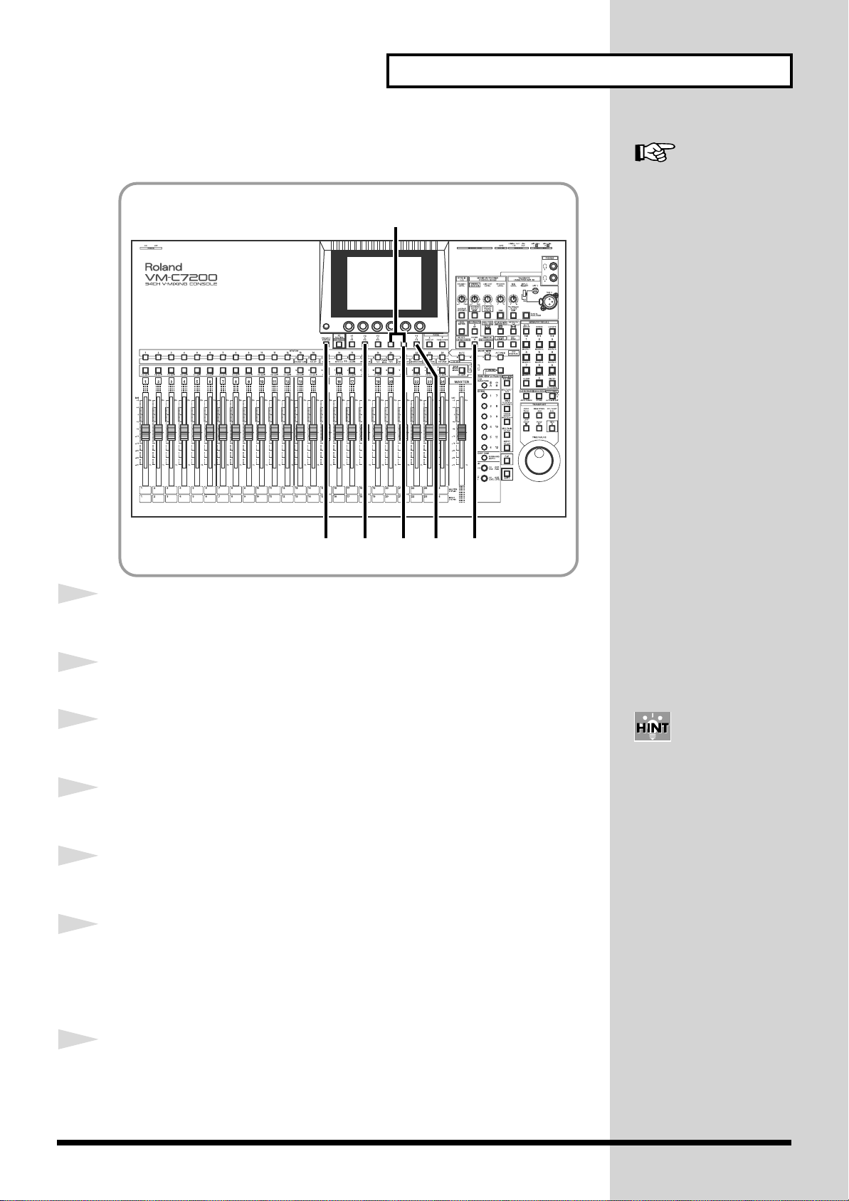
Before Mixing Operations
How to Operate This System
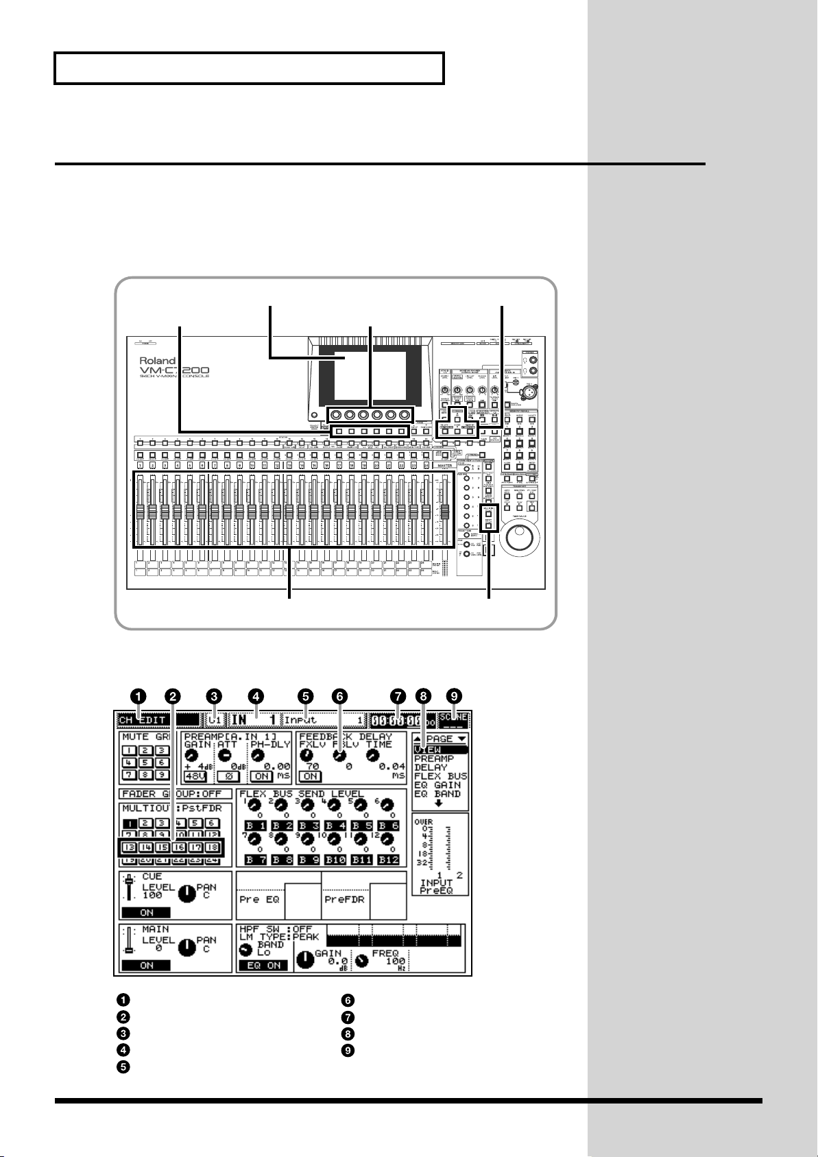
When operating this system, you’ll most frequently use the cursor, the
knobs [V1]-[V6], and buttons [F1]-[F6] beneath the display.
This chapter explains the display, and how these knobs and buttons interact
with the display.
fig.104
Display
Buttons F1-F6
Faders INPUT/MULTI IN buttons
The Display (example)
fig.204
Cursor buttons
Knobs V1-V6
24
Screen title
Cursor
Processor currently targeted
Current Section and Channel
Name of Channel
Parameter icon
Current time (Time Code)
Current page
Number of Scene currently
selected
Page 25
To Change Parameters
To change the value of a parameter, move the cursor to select a parameter,
and use the knobs [V1]-[V6], faders, and/or buttons [F1]-[F6] to change its
value, as described below.
To Move the Cursor
Before Mixing Operations
The cursor – a bold rectangle on the display – selects a single parameter or
group of parameters so that their values can be adjusted. To move the
cursor, press CURSOR [UP] [DOWN] [LEFT] [RIGHT].
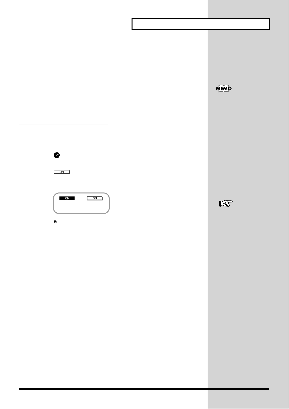
To Set the Values of Parameters
There are certain rules for setting parameters, as listed below. We
recommend you keep them in mind.
• parameters are set by turning knobs [V1]-[V6]. Turn the knob
below the parameter you wish to change.
• parameters are set by pressing buttons [F1]-[F6]. Press the
button for ON – this highlights the parameter in black on the display
– or OFF (not highlighted) below the parameter you wish to change.
ON OFF
• parameters are set by turning knobs [V1]-[V6] first, and then
pressing buttons [F1]-[F6](SET) to confirm the changes. Use the knob
and button below the parameter you wish to change. (Some
parameters can be set by pressing [F1]-[F6](SET) only.)
• Parameters shown as faders are set using the console’s faders. If the
fader indicated is selected by the cursor, you can also change its
value by turning the corresponding knobs [V1]-[V6].
The cursor does not appear
on a display where no
cursor selection is needed.
If you want to display or
change frequently used
parameters, or the value of
a single parameter on all of
the channels at once, you
can do this more easily by
using the console’s faders
(Owner’s Manual “Useful
Functions” p.58).
To Operate on [INPUT] or [MULTI IN] channels
To set the input source’s gain level and the tone, such as using the equalizer
and so on, press [INPUT] or [MULTI IN] to select the type of channel you
wish to setup.
With the selected button lit in red, you can control the behavior of each
source signal using the console’s faders or display controls.
25
Page 26
Mixing Operations
Now let’s do some mixing. This chapter describes two-channel – stereo –
mixing of connected sources that will be sent out from the system through
its MAIN OUT jacks.
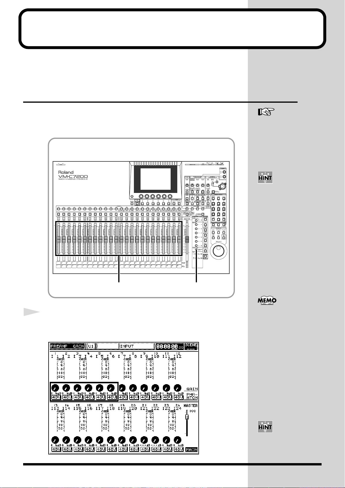
Setting the Input Gain
Let’s adjust the input gain levels of all of your connected instruments and so
on. (If you are working on digital connected sources, you do not have to
read this section.)
fig.107
Owner’s Manual “Gain,
Phantom Power Supply,
Phase and Attenuator”
(p.68)
As preset at the factory, all
channel numbers on the
console correspond to the
input numbers on the
processor. You may,
however, change the
channels’ connections or
work on multiple channels
at once (Owner’s Manual
“Selecting an input
channel’s signal source”
p.67).
1
2
1
Press [PREAMP GAIN].
[PREAMP GAIN] lights and the “PREAMP GAIN” display appears.
fig.206
If you selected DIGITAL IN
A/B as your source input,
these steps will not be
necessary.
You can also set the gain
level with the cursor and
knobs on the display.
26
Page 27
Mixing Operations
2
Use the fader of each channel you wish to adjust to set the
input gain level of its connected microphone/instrument/
audio device. (+4 to -64dB)
Do this by first turning up each instrument’s own output volume as much
as possible so that it produces a strong, loud signal. Next, on the console,
turn its channel’s input gain level as high as possible within the displayed
level-meter range. If the input gain goes beyond OVER, appears on the
level-meter.
fig.207
The fader, at this point,
controls the input gain
level of each channel. To
send signals from the Main
out, set the output level of
each channel (go to next
page).
If you are using a
condenser microphone or
any other similar
equipment, activate their
PHANTOM power.
You can also set each
channel’s PHASE ON/OF,
PHANTOM POWER ON/
OFF and ATTENUATOR if
required by the input
source.
When you have finished with these settings, you can set the channel levels
and L/R stereo pans.
27
Page 28
Mixing Operations
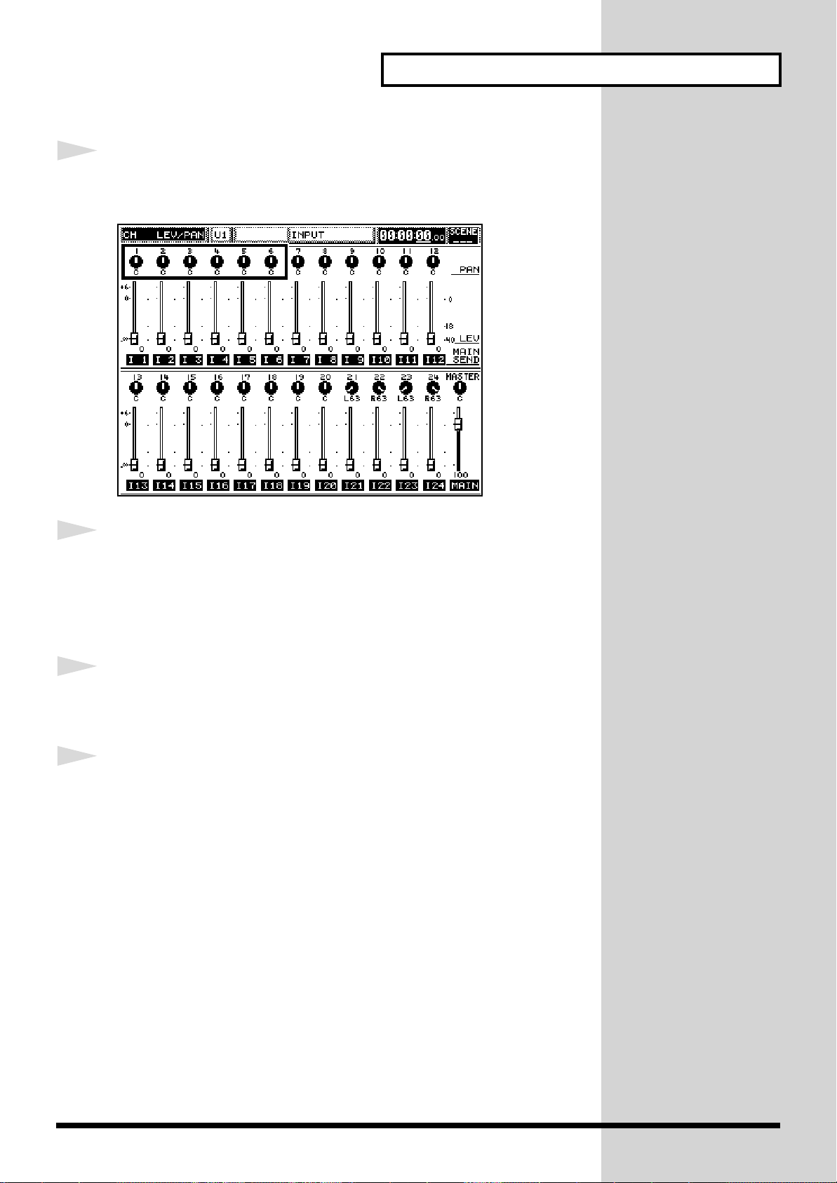
Setting the Channel Levels and L/R Pans
Here you can set the output level and L/R pan of each channel in the Main
out mix or the Cue bus. You can see each level and pan setting shown
numerically on the display.
fig.108
Owner’s Manual “Setting
up ON/OFF, SEND LEVEL
and PAN for a Channel”
(p.70)
1
3,5
3,5
Press [INPUT] or [MULTI IN] to select the type of channel you
2,3
4,5
SHIFT
1
28
wish to set up.
Page 29
Mixing Operations
2
3
Press [CH LEVEL].
[CH LEVEL] lights in red and the “CH LEV/PAN” display appears.
fig.208
Use the fader of the channel you wish to adjust to change its
4
5
output level.
To set the channel level at 0db (100), hold down [CH LEVEL] and press [CH
EDIT] of the channel you wish to set at 0db.
Press [CH PAN]
[CH PAN] lights in red and the “CH LEV/PAN” display appears.
Use the fader of the channel you wish to adjust to change its
stereo position.
Move the fader upwards for right (R) pan, downwards for left (L) pan.
To set the pan to center, hold down [CH LEVEL] and press [CH EDIT] of the
channel you wish to set the pan to center.
To send signals to the Cue bus, hold down [SHIFT] when pressing [CH
LEVEL] in Step 2, and when pressing [CH PAN] in Step 4. The buttons will
light in green.
When you have finished with these settings, let’s set the master level and
stereo balance.
29
Page 30
Mixing Operations
Setting the Master Level and Master Stereo Balance
Let’s now set the total output level and stereo balance for the Main out mix
containing all Input and Multi In sources.
fig.109
3
Owner’s Manual “Setting
Master Mix Levels and
Stereo Balance” (p.84)
1
2
3
12,4
Press [CH LEVEL] to light [CH LEVEL] in red.
Use the [MASTER] fader to set the master level for the Main
out.
Press [CH PAN] to light [CH PAN] in red.
30
Page 31

Mixing Operations
4
Use the [MASTER] fader to set the overall stereo balance of the
Main out.
Move the fader upwards for right(R) pan, downwards for left(L) pan.
31
Page 32

Mixing Operations
Adjusting a Signal’s Tone (Equalizer)
You can set the desired tone quality of each signal by using an equalizer
(EQ).
In this system, each channel provides a parametric EQ. You can select from
a 4-band- or a 3-band-plus-1-effect-type EQ. The high-range and low-range
bands are shelving type EQs. The middle-high-range and middle-low-range
bands are peaking type EQs.
fig.110
Owner’s Manual
“Adjusting Various
Channel Settings
(Equalizer, etc.)” (p.78)
1
2
35 4
12
Press [INPUT] or [MULTI IN] to select the type of channel you
2
32
wish to set up.
Hold down [CH EDIT] of the channel controlling the signal
whose tone you wish to adjust, and press [HI-MID/HI].
The “EQ BAND” editing page on the “CH EDIT” display appears.
Page 33

fig.209
Mixing Operations
3
4
5
Press [F1](EQ ON) to turn on the equalizer.
“EQ ON” highlights in black.
Press CURSOR [UP] [DOWN] to select the desired band.
HI (high-range), HI-MID (mid-high-range), LO-MID (middle-low-range),
LO (low-range).
Adjust the settings for the selected band.
GAIN
Turn [V2](GAIN) to add (“boost”) or reduce (“cut”) gain (-15.0 to +15.0dB).
FREQUENCY
Turn [V3](FREQ) to adjust the center frequency.
Q
Turn [V4](Q or RESO) to set the bandwidth.
To turn off the equalizer,
press [F1] again. “EQ
ON” returns to normal
.
When working with HI-MID and LO-MID bands, you can raise the volume
of the frequencies at the center of the selected band by raising the Q level
(0.36 to 16). (For the LO band, [V4] sets the HPF-FREQ bands.)
TYPE
Turn [V5](TYPE) to select the LO-MID band’s equalizer type. You can
choose from a variety of filter types. The equalizer returns to its normal
behavior when you select “TYPE PEAK”.
33
Page 34

Mixing Operations
Setting Up a Monitor
You can monitor the system through headphones connected to the
PHONES jack, or through monitoring speakers connected to the MONITOR
OUT jack. You will hear the same sound from both outputs. You can
monitor the Cue bus, the Main out, or any Flex Bus by itself.
fig.113
Owner’s Manual “Mixing
Procedure 2 (Output and
Monitor)” (p.84)
2
1
4
Press [SOURCE SELECT].
The “MONITOR SOURCE” sub-window appears on the display.
fig.211
13
34
Page 35

Mixing Operations
2
3
4
Turn [V1](SELECT) to select the output you want to monitor.
Turn [DIGITAL(MASTER)] to adjust the monitor out level.
• If you have a device connected to the LINE OUT jack on the console,
turn [LINE OUT LEVEL] to set the favorable line out level in
advance.
• If you are using headphones, turn [PHONES LEVEL] to adjust the
volume.
Press [F6](EXIT) to exit.
35
Page 36

Mixing Operations
Coupling Adjacent Channels
If you are editing a stereo source, you can couple adjacent odd- and evennumbered channels – changes you make to either channel will affect both.
fig.112
534
Owner’s Manual
“Simultaneously
Controlling the Signals of
Multiple Channels (Link
and Group)” (p.102)
1
2
21
Press [FADER UTILITY].
The “FADER UTIL” display appears.
Press [F1](CHANNEL LINK).
fig.210
36
Page 37

Mixing Operations
3
4
5
Press [PAGE UP] [PAGE DOWN] to display the type of
channels you want to link.
Select from “INPUT”, “MULTI IN”, or “FLEX BUS”.
Press CURSOR [UP] [DOWN] to select the group of six
channels containing the channels you want to link.
Press [F1]-[F6] to turn ON (black highlight) the Channel Link
of any pair you wish to couple.
To cancel Channel Link, press [F1]-[F6] again.
The following parameters cannot be linked.
• GAIN
• MAIN SEND PAN
• INPUT SOURCE
• SURROUND DEPTH
• SURROUND PAN
• MULTI OUT SEL
• 48V (PHANTOM) SW
• CH NAME
37
Page 38

Mixing Operations
Muting a Channel
You can mute a channel’s signal by using the [CH STATUS] buttons.
fig.111
Owner’s Manual “Muting a
channel (MUTE)” (p.77)
1
2
3
123
Press [INPUT] or [MULTI IN] to select the type of channel you
wish to mute.
Press [MUTE] to light [MUTE].
Press [STATUS] of the channel you wish to mute.
The muted channel’s [STATUS] button lights in red.
38
Page 39

Storing a Project
The current state of the console settings can be stored at any time by
updating the Project created on a memory card in the beginning of the
session. Let’s store the system’s current state as a Project.
fig.114
Mixing Operations
Owner’s Manual “Storing
and Recalling All Mixer
Settings (Project)” (p.50)
2
1
2
1
Hold down [SHIFT] and press [STORE].
The “CONFIRM / Store Current Project OK?” message appears.
Press [F5](OK), and then press [F6](EXIT) after storing is
completed.
To cancel, press [F6](CANCEL).
You cannot store a Project
without an inserted
memory card that holds a
Project created in advance
(QUICK START: p.16).
39
Page 40

Using Sub Outputs
Signals can be sent from the system’s MAIN OUT to a mixdown recorder or
a stage speaker system. They can also be sent to other destinations, such as
studio monitors, or even to individual tracks of a multi-track recorder.
Setting Up Monitor Sends for Studio or Stage
The system’s ASSIGNABLE OUTs (Owner’s Manual “Routing Signals to MULTI
OUTs and ASSIGNABLE OUT Jacks” p.93)
a performer in another room –perhaps a studio – or on a stage. You can
easily set up two such independent stereo monitoring systems: “STUDIO 1”
and “STUDIO 2”. ASSIGNABLE OUTs 1 and 2 can be used as L and R
outputs to “STUDIO 1”, and ASSIGNABLE OUTs 3 and 4 as L and R outputs
to “STUDIO 2”.
1-4 can send signals to monitors for
Connect a stereo headphone or monitor speaker amplifier to the STUDIO
output jacks.
Each monitor mix can be tailored to the needs of the performer listening to
it. “STUDIO 1” has a dedicated level knob. This makes “STUDIO 1” handy
for the monitoring of vocals on a stage – you can use this knob to quickly
lower the “STUDIO 1” volume if the undesirable howling occurs.
To Select Signals for Studio Monitors
fig.115
432
STUDIO 1
level knob
Owner’s Manual “Setting
Up Monitor Sends For
Studio Or Stage (STUDIO 1
or 2)” (p.95)
40
1
Page 41

Using Sub Outputs
1
2
Press [SOURCE/STUDIO2].
The “STUDIO1/2” display appears.
fig.212
Press [PAGE UP] [PAGE DOWN] to go to the “STUDIO 1” or
3
4
“STUDIO 2” page.
Turn [V1](SOURCE SELECT) to select the type of source signal
you wish to monitor.
The following can be selected.
• Input channel 1-24
• Flex Bus 1-12
• Cue bus L/R
• Monitor L/R
• Main out L/R
Turn [V2](LEVEL) to adjust the send level.
The source signals you selected in Step 3 can be heard from ASSIGNABLE
OUTs 1 and 2 for “STUDIO 1” L/R, or ASSIGNABLE OUTs 3 and 4 for
“STUDIO 2” L/R.
41
Page 42

Using Sub Outputs
To Talk to Someone on a Stage or out in a Studio (Talkback)
The Talkback feature allows you to talk to a performer or assistant on a stage
or in a studio by speaking into the Talkback microphone built into the
console. This microphone can be routed to a monitor speaker or other
monitoring device.
fig.116
Owner’s Manual “Talkback
and Slate to Player” (p.100)
MIC
1
2
11,2
Set [INPUT SELECT] to MIC 1.
Before switching the [INPUT SELECT], turn [MIC LEVEL] to turn the mic
level to 0.
Hold down [TALKBACK/SLATE] while speaking into the
microphone. Your voice is sent to the Main out and/or the Cue
bus. The Talkback/Slate is normally active only when the
button is held down (it lights in red).
To change the Talkback microphone’s volume, turn [MIC LEVEL].
To prevent howling, be sure to lower the volume of the monitor
speakers first when using the Talkback function.
You can also send your
voice to various other
destinations, such as the
ASSIGNABLE OUTs or
Flex Busses.
42
Page 43

Flex Bus
Each mixing processor provides 12 unique multi-purpose busses– these are
called “Flex Busses.” A bus – be it a Flex Bus or traditional recording, mixing
or Aux bus – is a pathway down which multiple signals can be sent to a
common destination. The signals assigned to a Flex Bus can be sent out of
the system through various outputs, or can even be directed into another
Flex Bus within the system. This allows you to send signals through external
signal processors or internal effects, or to monitors for performers on the
stage or in the studio.
Example 1
You may wish to use reverb on some channels before sending them to the
Main out mix. Route them to a Flex Bus connected to the desired effect.
Example 2
Using Sub Outputs
You can record to individual tracks on an 8 track multi-track recorder by
assigning your input channels to any of eight Flex Busses, and using the
MULTI OUTs or ASSIGNABLE OUTs to send each Flex Bus to one of the
eight tracks on the recorder.
Example 3
Since you can adjust each channel’s send level to a Flex Bus, you can create
up to eight separate, fully controllable stage monitor mixes using eight Flex
Busses routed to ASSIGNABLE OUTs 1-8.
Let’s start by assigning Flex Busses to outputs.
You may couple a pair of
adjacent Flex Busses and
use them as stereo Flex
Busses (QUICK START:
p.36).
43
Page 44

Using Sub Outputs
Flex Bus Output (MULTI OUT/ASSIGNABLE OUT)
Each of the Flex Bus signal can be routed to a MULTI OUT/ASSIGNABLE
OUT. You can send its signal to multi-track recorders, external signal
processors, or to stage monitors, for example.
The MULTI OUTs are primarily used for 24 channel digital recording
outputs – which calls for an additional purchased VM-24E – but can also be
routed to ASSIGNABLE OUT jacks for analog output.
fig.117
35 34
Owner’s Manual
“Outputting signals
directly from a Flex Bus”
(p.86), “Routing Signals to
MULTI OUTs and
ASSIGNABLE OUT Jacks”
(p.93)
1
2
6
12
Press [FLEX BUS MASTER 1-12].
If you wish to edit Flex Busses 9-12, proceed to Step 4.
Hold down [CH EDIT] on the channel strip numerically
corresponding to the Flex Bus you wish to edit, and press
[MAIN/CUE].
The “MAIN/CUE” editing page on the “CH EDIT” display appears.
44
Page 45

fig.213
Using Sub Outputs
3
4
5
Press CURSOR [UP] [DOWN] to select the middle field. Turn
[V2](BUS MODE) to select “EXT”, and then press [F2](SET) to
confirm your choice. (Flex Busses 9-12 do not call for this step.)
The Flex Bus is now set to External.
Press CURSOR [UP] to move the cursor to the upper field.
Turn [V3](MULTI OUT SEL) to select the MULTI OUT
number, and then press [F3](SET) to confirm.
The Flex Bus signals are normally sent out from the corresponding MULTI
OUTs, but can also be routed to the following ASSIGNABLE OUT jacks for
analog output.
• MULTI OUT 17 - ASSIGNABLE OUT 1
• MULTI OUT 18 - ASSIGNABLE OUT 2
• MULTI OUT 19 - ASSIGNABLE OUT 3
If an effect has been
inserted on a Flex Bus, it
may lose its effect when
you switch from “INT” to
“EXT”. When this happens,
set the effect’s parameters
again (QUICK START:
p.54).
6
• MULTI OUT 20 - ASSIGNABLE OUT 4
• MULTI OUT 21 - ASSIGNABLE OUT 5
• MULTI OUT 22 - ASSIGNABLE OUT 6
• MULTI OUT 23 - ASSIGNABLE OUT 7
• MULTI OUT 24 - ASSIGNABLE OUT 8
Press [CH LEVEL].
The Flex Bus’ signals are now set to exit the system from the selected MULTI
OUT or ASSIGNABLE OUT jacks.
45
Page 46

Using Sub Outputs
Flex Bus Output (Internal)
Flex Bus signals can also be routed into the Main out mix. This is convenient
if you are planning to add internal effects to signals used in the main mix.
fig.118
Owner’s Manual “Sending
Flex Bus signals to internal
destinations” (p.87)
3534
1
12
Press [FLEX BUS MASTER 1-12].
If you wish to edit Flex Busses 9-12, proceed to Step 4.
46
Page 47

Using Sub Outputs
2
Hold down [CH EDIT] on the channel strip numerically
corresponding to the Flex Bus you wish to edit, and press
[MAIN/CUE].
The “MAIN/CUE” editing page on the “CH EDIT” display appears.
fig.213
3
4
5
Press CURSOR [UP] [DOWN] to select the middle field. Turn
[V2](BUS MODE) to select “INT”, and then press [F2](SET) to
confirm your choice.
The Flex Bus signals are now set to Internal.
Press CURSOR [DOWN] to move the cursor to the lower field.
Turn [V1](MAIN LEVEL) to adjust the Main out send level.
The Flex Bus’ signals are now routed into the Main out mix.
47
Page 48

Using Sub Outputs
Sending Signals to a Flex Bus
Now let’s assign some signals to a Flex Bus.
You may wish to monitor a Flex Bus directly – this is possible only when the
Flex Bus is set to External (QUICK START: p.44). To monitor the Flex Bus’
signals, select “FBUS 1-12” at “Setting Up a Monitor” (QUICK START: p.34).
fig.119
Owner’s Manual “Setting a
channel’s send level and
send point to Flex Buses”
(p.72)
2 1
1
63 24
Press [INPUT] or [MULTI IN] to select the type of channel
signals you wish to send to a Flex Bus.
48
Page 49

Using Sub Outputs
2
Press FLEX BUS [1]-[6] (lights in red) – or hold down [SHIFT]
to select [7]-[12] (lights in green) – to select the Flex Bus to
which you want to send the signals.
The “FBUS SEND” display appears.
fig.214
3
4
5
6
Use the channel faders to adjust each channel’s send level to
the Flex Bus.
Use the [MASTER] fader to adjust the Flex Bus’ overall level.
Repeat Steps 1-4 to assign signals to other Flex Busses.
Press [CH LEVEL].
49
Page 50

Using On-Board Effects
In this system, there are two internal effects available to the Input and Multi
In channels, and an additional effect provided for the Main out and
monitors. In addition, you can install optional VS8F-2 Effects Expansion
Boards – sold separately – allowing the system to produce up to nine effects
simultaneously from a single mixing processor (see list below).
• FX-1, FX-2 - Pre-installed
• FX-3, FX-4 - VS8F-2 (optional) installed to EFFECT A inside the
processor
• FX-5, FX-6 - VS8F-2 (optional) installed to EFFECT B inside the
processor
• FX-7, FX-8 - VS8F-2 (optional) installed to EFFECT C inside the
processor
• MASTER FX - Pre-installed. Only for MASTER OUT and monitors.
Read OWNER’S MANUAL
for the Processor
“Installing Effects
Processors (VS8F-2)” (p.13)
to learn about the
installation of the VS8F-2.
On using the effects, the following steps will be necessary.
1. Make a decision as to where you wish to insert an effect.
You may insert the effect on a Flex Bus to create a send-return loop effect,
or directly on an input channel.
2. To create a send-return loop effect, send the signals to which you wish to
apply the effect to a Flex Bus that is routed to the Main out.
3. Select the desired effect.
Each input also has its own feedback-type delay that produces a delay effect
without using the on-board effect.
Now, let’s add some effects to your signals.
50
Page 51

Send-Return Loop Effect
Let’s try creating a send-return loop effect using the internal effects 1-8.
fig.120
7
6 2,5
Using On-Board Effects
Owner’s Manual
“Determining the effect
position” (p.110)
1
143
Press [EFFECTS 1-8].
The “EFFECTS MENU” display appears.
fig.215
51
Page 52

Using On-Board Effects
2
3
4
Press CURSOR [UP] [DOWN] to select the FX field.
FX-1-3 are located in the upper field, FX-4-6 in the middle, and FX-7-8 in the
lower. If you have not installed an optional VS8F-2, you can only select FX1 or FX-2.
Press [F2], [F4], or [F6] to “EDIT” the effect.
The “EFFECT (1-8)” editing display appears.
Press [PAGE DOWN] to go to the “ASSIGN” page.
At this point, you set the insertion point of the effect.
fig.216
5
6
7
Flex Bus channel to which an effect is inserted.
Flex Bus channel to which an effect is not inserted.
Press CURSOR [UP] [DOWN] to select L or R.
Turn [V4](SEND LEVEL) to adjust the level to be sent into the
effect, and [V5](RETURN LEVEL) to adjust the effect’s output
level.
The setting’s range is 0 to 127, with no boost or cut applied to the gain (0dB)
at 100.
Turn [V2](POSITION) to select “SEND/RTN”
The effect is automatically assigned to its like-numbered Flex Bus.
52
Page 53

Using On-Board Effects
8
9
Set the Flex Bus’ output destination to the Main out.
1. Press [FLEX BUS MASTER 1-12].
2. Hold down [CH EDIT] numerically corresponding to the Flex Bus to
which you have inserted the effect, and press [MAIN/CUE].
3. Press CURSOR [UP] [DOWN] to select the middle field. Then turn
[V2](BUS MODE) to select “INT”, and then press [F2](SET) to confirm.
Route the input channels that hold the signals to which you
wish to apply the effect to the selected Flex Bus.
1. Press [INPUT] or [MULTI IN] to select the type of channel signals you
wish to send to the Flex Bus.
2. Press FLEX BUS [1]-[6] (lights in red) – or hold down [SHIFT] to select [7]-
[12] (lights in green) – to select the Flex Bus to which you wish to send the
signals.
3. Use the channel faders to adjust each channel’s send level to the Flex Bus.
4. Use the [MASTER] fader to adjust the Flex Bus’ overall level
Go to QUICK START : p.43
for Flex Bus setup
instructions.
.
FLEX BUS
MASTER 1-12
SHIFT
CH EDIT
knob
V2
Faders
F2
Cursor
UP/DOWN
MAIN/CUE
FLEX BUS
[1] – [12]
[INPUT]
[MULTI IN]
53
Page 54

Using On-Board Effects
Setting the Onboard Effect Position and Value
You can insert an internal effect at any of several points along a signal’s
path. Most effects are inserted on a Flex Bus or the Main out, but there are
some effect types you may wish to insert directly into an Input or Multi In
channel.
First, make a decision as to where you wish to insert an effect. Then adjust
the appropriate send/return values.
fig.120
6 2,5
7
Owner’s Manual
“Determining the effect
position” (p.110)
1
143
Press [EFFECTS 1-8] to select FX-1-8, or [SP MODELING
(MASTER FX)] for MASTER FX.
The “EFFECTS MENU” or “MST FX MENU” display appears.
54
fig.21
Page 55

Using On-Board Effects
2
3
4
Press CURSOR [UP] [DOWN] to select the FX field.
FX-1-3 are located in the upper field, FX-4-6 in the middle, and FX-7-8 in the
lower (“MST FX MENU” does not call for this step).
If you do not have an optional VS8F-2 installed, you can only select FX-1 or
FX-2.
Press [F2], [F4], [F6], or [F2] on “MST FX MENU” to “EDIT”.
The “EFFECT (1-8)” or “MASTER FX” display appears.
Press [PAGE DOWN] to go to the “ASSIGN” page.
At this point, you set the insertion point of the effect.
fig.216
5
6
Flex Bus channel to which an effect is inserted.
Flex Bus channel to which an effect is not inserted.
Press CURSOR [UP] [DOWN] to select L or R.
(“MST FX MENU” does not call for this step.)
Turn [V4](SEND LEVEL) to adjust the level to be sent into the
effect, and [V5](RETURN LEVEL) to adjust the effect’s output
level.
The setting’s range is 0 to 127, with no boost or cut applied to the gain (0dB)
at 100.
55
Page 56

Using On-Board Effects
7
Turn [V2](POSITION) to define the insertion point of the
effect.
The insertion points are as listed below. (Turn [V1] for “MASTER FX” to
select from the following: OFF, MAIN, MONITOR.)
• OFF - No effect
• INPUT PRE EQ - Insert before EQ on Input channels
• INPUT PRE FDR - Insert before fader on Input channels
• MULTI IN PRE EQ - Insert before EQ on Multi In channels
• MULTI IN PRE FDR - Insert before fader on Multi In channels
• SEND/RTN (INT) - Effect receives mono input from a Flex Bus and
produces a stereo effect that can be routed to Main out or Cue bus,
etc. Signal is sent to each effect via its like-numbered Flex Bus.
• INT FBUS - Insert on Flex Bus (Internal mode)
• EXT FBUS - Insert on Flex Bus (External mode)
• MAIN - Insert on Main out
• MONITOR - Insert on Monitor out
The precise insertion point
of the effects can be seen on
the “Block Diagram” that is
supplied with the
processor.
examples
• When using an equalizer or compressor on an input signal itself,
insert the effect directly on the Input or Multi In channel.
• When using a reverb for multiple channels, use SEND/RTN (INT) to
create a mono-send/stereo-return loop effect, or insert the effect on a
Flex Bus for a mono-send-return loop effect.
• When using the Total Compressor on your entire mix, insert it on the
Main out.
56
Page 57

Using On-Board Effects
8
If you have inserted the effects on an Input or Multi In channel
or a Flex Bus, turn [V1](CHANNEL SELECT) to select the
intended channel/bus, and press [F1](SET).
The insertion point and the send/return values have been set.
Effects can be inserted on
Flex Busses 1-8.
57
Page 58

Using On-Board Effects
Selecting the Effects
A selection of 200 Preset Libraries (P000 to P199) are provided for the effects.
You can select a Library that suits your purpose, and copy it to an effect from
1 through 8, or the Master effect.
fig.121
Owner’s Manual “Selecting
the effect library” (p.113)
4425
1
2
13
Press [EFFECTS 1-8] to select “FX-1-8”, or [SP MODELING
(MASTER FX)] for “MASTER FX”.
The “EFFECTS MENU” or “MST FX MENU” display appears.
Press CURSOR [UP] [DOWN] to select the FX field.
FX-1-3 are located in the upper field, FX-4-6 in the middle, and FX-7-8 in the
lower.
(“MST FX MENU” does not call for this step.)
58
Page 59

Using On-Board Effects
3
4
Press [F1], [F3], [F5], or [F1] on “MST FX MENU” to call up the
“LIBRARY”.
The “COPY EFFECTS LIBRARY” sub-window opens on the display.
fig.217
First, turn [V1](SELECT GROUP) to select “U” (User’s) or “P”
5
(Preset) group. (As preset at the factory, the User’s group
holds the same effects as the Preset group.) Next, turn
[V2](SELECT NUMBER) to select the desired effect (000 to 199)
(Owner’s Manual “Algorithm List” p.119).
Press [F1](PREVIEW) to try out the effect you have selected (“PREVIEW”
highlights in black when turned on). To cancel the preview, press [F1] again.
The following algorithms require two circuits.
• Voice Transformer
• Vocoder2
• Mastering Tool Kit
• 31-Band Graphic Equalizer
Press [F2](CP/LOAD) to confirm your effect choice.
The selected effect has been set.
59
Page 60

Using On-Board Effects
Using a Channel’s Feedback Delay (Channel Delay)
Each channel input has its own delay effect positioned before the EQ in its
signal path. The delay is a monaural in/out, and provides various delay
effects, including a feedback echo.
fig.122
37
5 86
Owner’s Manual “Adding
a delay-based echo
(Feedback Delay)” (p.81)
1
2
12
4
Press [INPUT] or [MULTI IN] to select the type of channel you
wish to set up.
Hold down [CH EDIT] of the channel you wish to apply the
delay effect, and press [DELAY].
The “DELAY” page of the “CH EDIT” display appears.
60
Page 61

fig.218
Using On-Board Effects
3
4
5
6
7
Press [F1](DLY ON) to turn on the Channel Delay.
“DLY ON” highlights in black.
Press CURSOR [DOWN] to move the cursor to the lower field.
Turn [V1](DIRECT) to adjust the dry-out level– the original,
un-delayed signal.
Turn [V4](DELAY TIME) to adjust the delay time.
The DELAY TIME sets both the basic delay (shown as TIME) and the
spacing between the repeating feedback delays (shown as DISTANCE).
The selected delay time is also shown in samples.
Turn [V2](DLY LEV) to adjust the delay level.
8
Turn [V3](F-B LEV) to adjust the feedback level.
The feedback level determines the number of times the delay repeats on
itself.
The channel’s signal is now being processed by the channel’s delay effect.
You can also use the
channel delay as a Comb
filter (Owner’s Manual:
p.233).
61
Page 62

Other Important Features
Storing a Mixing State (Scene)
A Scene is a complete set of mixer settings that can be stored at any point
during work on a Project. A Project can store 100 Scenes (00-99), that can
easily be recalled.
Items Stored in a Scene
A Scene holds the level and pan settings of Input and Multi In channels, the
Main out, Cue bus, and Flex Busses. It also stores the settings of all
equalizers, delays, and internal patch connections.
To Store a Scene
fig.123
2
3
Owner’s Manual “Storing/
recalling/erasing a scene”
(p.47)
1
62
Page 63

Other Important Features
1
2
Hold down [SHIFT] and press [SCENE].
The “SCENE” display appears.
Turn [V1] to select the Scene number you wish to store.
The Scene memory
function requires an
inserted memory card on
which a Project has been
created or selected.
3
The black highlighted field indicates the selected Scene.
Press [F3](REGIST).
The current settings are stored as a Scene.
You can also use the tenkey buttons to store/recall
scenes.
63
Page 64

Other Important Features
To Recall a Scene
fig.124
2
Owner’s Manual “Storing/
recalling/erasing a scene”
(p.47)
1
3
Hold down [SHIFT] and press [SCENE].
The “SCENE” display appears.
1
64
Page 65

Other Important Features
2
3
Turn [V1] to select the Scene number you wish to recall.
The black highlighted field indicates the selected Scene.
Press [F1](RECALL).
The selected Scene is recalled.
65
Page 66

Other Important Features
Setting Signal Routings on the Display (Virtual Patchbay)
You can establish the routing of signals by making connections between
input jacks and ASSIGNABLE OUT jacks using virtual cables shown on the
display.
fig.125
3
Owner’s Manual “Virtual
patchbay” (p.60)
1
12
Hold down [SHIFT] and press [EZ ROUTING].
The “EZ ROUTING” display appears.
fig.219
66
Page 67

Other Important Features
2
3
Press CURSOR [UP] [DOWN] [LEFT] [RIGHT] to select a
group of six input jacks or output jacks.
Turn [V1]-[V6] to change their connections.
• For internal connections using the Virtual Patchbay, signals can also
be assigned to several destinations. Multiple signals, however, can
not be simultaneously assigned to a single destination.
Possible
IN 1 OUT 1
IN 2 OUT 2
IN 3 OUT 3
IN 4 OUT 4
Impossible
IN 1 OUT 1
IN 2 OUT 2
IN 3 OUT 3
IN 4 OUT 4
The MULTI OUT
connection thread can be
cut off by turning the knob
all the way to the left. You
cannot, however, cut
connections between PRE
AMP and INPUT CH.
67
Page 68

Other Important Features
Simultaneously Adjusting the Levels of Multiple Channels
You can group multiple channels together, allowing you to control all of the
channels simultaneously. You can use, for example, a single fader to boost
or cut all of the grouped channels’ levels at once.
This can be convenient in situations where you want to maintain volume
balances between a set of channels while raising or lowering their overall
level, such as when working with multiple microphones on a drum kit.
To Create a Group of Channel Faders (Fader Group Master)
You can control the volume of multiple channels’ signals using a single
Fader Group Master fader. By raising and lowering this fader, the levels of
all channels registered in the group are raised and lowered simultaneously.
You can set up as many as 24 Fader Groups.
The following channels can be grouped.
fig.126
Owner’s Manual
“Simultaneously
Controlling the Signals of
Multiple Channels (Link
and Group)” (p.102)
• Input channels 1-24
• Multi In channels 1-24
• Flex Bus Masters 1-12
• MIDI faders 1-16
4
68
132
Page 69

Other Important Features
1
2
Press [FADER GROUP MASTER 1-24]
The “FADER GROUP” display appears – the faders now function as Fader
Group Masters.
Press [CH EDIT] of the Fader Group you wish to edit.
The “CH EDIT” display appears with the Fader Group setting screen.
fig.220
3
4
In the lower right “GROUP VIEW” field of the screen, use
CURSOR [UP] [DOWN] [LEFT] [RIGHT] to select a set of six
channels containing the first channel you wish to include in
the group.
Press [F1]-[F6] to turn ON (black highlight) / OFF (normal) the
desired channel faders. Then repeat Steps 3-4 to register all of
the desired channels in the Fader Group selected in Step 2.
If you want to register or change another Fader Group, start over from Step
2.
To change the levels of channels registered in the group, press [FADER
GROUP MASTER 1-24] to light [FADER GROUP MASTER 1-24], and use
the group’s master fader.
You can also mute a Fader
Group in the same way as a
normal channel by pressing
[MUTE] (QUICK START:
p.38).
69
Page 70

Other Important Features
To Mute a Group of Multiple Channels (Mute Group)
You can also mute a group of multiple channels simultaneously by using the
Mute Group function.
This system provides nine Mute Groups. By turning a Mute Group on or off,
all channels registered in the group are muted or un-muted simultaneously.
The following channels can be grouped.
fig.127
• Input channels 1-24
• Multi In channels 1-24
• Flex Bus Masters 1-12
• Fader Group Masters 1-24
[1] ~ [9] buttons
Owner’s Manual
“Simultaneously
Controlling the Signals of
Multiple Channels (Link
and Group)” (p.102)
70
342
1
Page 71

Other Important Features
1
2
Hold down [SHIFT] and press [MUTE GROUP].
The “MUTE GROUP” display appears.
fig.221
Press [PAGE UP] [PAGE DOWN] to select the Mute Group
3
4
you wish to set up.
For example, if you wish to set up Mute Goup 2, select “GRP 2”.
Press CURSOR [UP] [DOWN] [LEFT] [RIGHT] to select the set
of six channels that contains the first channel you want to
register in the Mute Group.
Press [F1]-[F6] to turn ON (black highlight) / OFF (normal) the
Mute Group. Then repeat Steps 3-4 to register all of the desired
channels to the Mute Group selected in Step 2.
If you want to register or change another Mute Group, start over from Step
2.
To turn a Mute Group on or off, press [MUTE GROUP] to light [MUTE
GROUP], then press the corresponding [1]-[9] button on the numeric
keypad.
71
Page 72

Some Special Features
This chapter introduces some other special features.
The instructions for their use can be found in the Owner’s Manual.
The Spectrum Analyzer
This system is equipped with a Spectrum Analyzer, with which you can
measure the frequency characteristics of signals. This Spectrum Analyzer
(referred to as “analyzer” for the remainder of this section) divides input
signal frequencies into 31 narrow bands, and displays the momentary level
of each band on a graph in real-time. This allows you to become visually
acquainted with the frequency characteristics of your recorded work, the
frequency response of a concert hall, or even to pinpoint problem frequency
ranges when a howling occurs.
fig.222
Owner’s Manual “Using
the Spectrum Analyzer”
(p.184)
72
Some Examples of How to Use the Spectrum Analyzer
• To create a perfectly balanced mix, you can use the analyzer to view
the distribution of frequencies in your material. This can help you
determine what EQ is needed during the mixing process.
• Using the built-in noise generator, you can inspect the frequency
response of a concert hall by analyzing microphone signals that
capture a noise burst sounded in the hall.
• You may use a built-in 31-band graphic equalizer – the same number
of bands as the analyzer – to monitor and adjust frequency balance
problems in real time.
Page 73

5.1 Surround
This system supports multi-speaker surround sound.
Some Special Features
A normal stereo audio system consists of two speakers – left and right in
front of the listener – for stereo playback. A surround system creates a threedimensional sound field with three to six speakers located in the front and
rear, as well as to the left and right. You can create surround sound by
positioning and adjusting the Flex Bus outputs on the “SURROUND”
editing display.
fig.223
Owner’s Manual “PAN
and DEPTH for using
SURROUND” (p.73),
“Surround Output” (p.91)
There are certain conventions for surround sound, according to the number
and positions of the speakers. This system supports three of the most
popular surround modes, as shown below.
fig.010
2+2 4 speakers
Front L
Rear L
Rear R
Front R
3+1 4 speakers
Front L
Rear
Front R
Center
3+2+1 6 speakers
Front L
Subwoofer
Center
Rear RRear L
Front R
73
Page 74

Some Special Features
Speaker Modeling
This system provides a powerful collection of exclusive Roland speaker
modeling effects.
With Roland’s DS-90 Powered Monitors connected, you can simulate almost
any speaker system, ranging from commonly used pro monitor speakers to
those found on small TV sets and portable radios. This allows you to try out
your mix on a variety of virtual speaker systems.
Speaker Modeling works best with digital speakers such as Roland’s DS-90
Powered Monitors – other speakers may not be able to attain the same
degree of sonic accuracy.
With the provided library of speaker modeling effects, you can easily
simulate a wide range of speakers, including bright-sounding powered
monitors, compact full-range speakers that might be used in a recording
studio, or the tiny speakers of a radio-cassette recorder.
Owner’s Manual “Using
the Speaker Modeling
function” (p.109), “Speaker
Modeling” (p.170)
If you are using the following speakers on your PA system, you may find it
easy to keep the frequency characteristics at a flat level.
• DS-90
• MS-50
• SST-151
• SST-251
• SSW-351
74
Page 75

Using EZ Routing Templates
The system provides nine preset EZ Routing templates that can help you
quickly configure your console for a wide variety of applications. These
templates cover a range of mixing tasks: studio and stage recording, mixing,
live sound with stage monitors, and MIDI synchronization for working with
bands that play along to MIDI sequencers, for example. They also suggest
some of the many ways in which you can configure this highly flexible
system.
The nine templates are as listed below.
• 8 Track MDM With MIDI Sound Module Recording
• 24 Track Digital Recording Session With a Rock Band
• 24 Track Mixing Session From Digital Tape
• 94 Channel Mixing Session
• Live Rock Band Concert Mix With 16 Track Digital Recording
• Live Jazz Ensemble With 8 Track Digital Recording
• Public Address, Large Meetings and Media Presentations
• Post Production Recording and Surround Sound Mixing
• Basic Mixer Setup Example
Now let’s try out some of the EZ Routing templates.
75
Page 76

Using EZ Routing Templates
8 Track MDM With MIDI Sound Module Recording
This EZ Routing template configures the system for recording live elements (vocal, guitar, etc.) along
with sequenced MIDI backing tracks (synthesizers, rhythm-box, etc.) on an 8 track digital recorder.
(VM-C7200/C7100 Libraries “8 TRACK MDM WITH MIDI SOUND MODULE RECORDING” p. 3)
See your Owner’s Manual for more details.
.
Front Panel on the Processor
E.Bass
Syn.Bass
Sampler
Bass Drum
L
R
11
1
Snare Drum
Rhythm Module
E.Guitar
DI DI
12 13 14 15 16 17 18 19 20
2 3 4 5 6 87 9 10
Rhythm L/R
Rear Panel on the Console
Powered Speaker
in the Control Room
Piano L/R
E.Piano
A.Guitar
Strings L/R
Chorus
Synthesizer
Lead Vocal
Brass L/R
FLEX BUS
OUT 9-12
Digital OUT
Digital IN
Monitor Speaker,
Headphone for Players
To the Mixing Console
DAT/MD recorder
Amp
Monitor Speaker
Amp
INPUT channel
1 Rhythm module
(Bass Drum)
2 Rhythm module
(Snare Drum)
3 Rhythm module (L)
4 Rhythm module (R)
5 E. Piano (L)
6 E. Piano (R)
7 Strings (L)
8 Strings (R)
9 Brass (L)
10 Brass (R)
11 Sampler (L)
12 Sampler (R)
13 Syn. Bass
14 E. bass
15 E. Guitar
16 A.Guitar
17 Chorus 1
18 Chorus 2
19 Chorus 3
20 Vocal
22 DAT (L)
23 DAT (R)
24 Slate
MULTI-IN channel
1 E. bass
2 E. Guitar
3 A.Guitar
4 Chorus 1
5 Chorus 2
6 Chorus 3
7 Vocal
8 Vocal (additional)
Rear Panel on the Processor
76
Digital Multi-track Tape Recorder
(TASCAM/ADAT)
8 ch
To the Mixing Processor
Roland DIF-AT
(Interface Box)
VM-24E
(Option)
MIDI Connections
Connect the MIDI cable to the
MIDI OUT socket on the MIDI
sync device (sequencer), and
to the MIDI IN socket on the
sound module.
Page 77

Using EZ Routing Templates
1
2
Make your connections as shown on the left.
• Use MIDI cables to connect the system to your MIDI devices (sound
module, sampler, digital multi-track recorder, etc.).
• You can set up as many as four monaural monitor outputs for your
performers. Connect their headphones or monitor amplifiers to FLEX
BUS OUTs 9-12.
• Route any guitar or electric bass through direct boxes or a compact
effect processor connected to the system input.
Turn on the power to your devices in the following sequence.
1. Digital multi-track recorder
2. Digital devices (DAT, MD recorder, etc.)
3. Analog devices (instruments, sound modules, effects processors,
microphones, electric guitars, etc.)
4. Mixing processor
5. Mixing console
QUICK START “Turning
On the Power” (p.10)
3
4
6. Audio equipment (amplifiers, speakers)
Select the EZ Routing template for 8 Track Recording With
MIDI Sound Modules.
1. Press [EZ ROUTING], and then press [F1](TEMPLATE)
2. Turn [V1](SELECT GROUP) to select group “P”, and then turn
[V2](SELECT NUMBER) to select “P000: MIDI+8TrREC”.
3. Press [F2](CP/LOAD).
• The “MIDI+8TrREC” template has been recalled.
Configure your MIDI devices to be synchronized to the
system.
• As set at the factory, the console is set to transmit MTC (MIDI Time
Code) as the master timing reference. Set your external MIDI slave
devices to sync to MTC.
• Consult your MIDI devices’ documentation to learn how to set them
up for external MTC synchronization.
Owner’s Manual “Calling
Up Stored Connections (EZ
Routing)” (p.59)
Owner’s Manual “Using
with MIDI Devices” (p.222)
77
Page 78

Using EZ Routing Templates
5
6
7
Set the input gain of each signal on the console.
1. Press [INPUT].
2. Press [PREAMP GAIN].
3. Use the faders to adjust the input gain level of each source.
• If you are using any condenser microphones, activate their
PHANTOM power.
Adjust each EQ as necessary.
1. Press [CH EDIT] on the desired channel.
2. Press [PAGE UP] [PAGE DOWN] to select the “EQ BAND” page.
3. Use CURSOR [UP] [DOWN], [V1]-[V6] and [F1]-[F6] to set the EQ.
Set the channel levels.
1. Press [CH LEVEL].
2. Adjust each channel’s output level using its fader.
Owner’s Manual “Gain,
Phantom Power Supply,
Phase and Attenuator”
(p.68)
Owner’s Manual
“Adjusting Various
Channel Settings
(Equalizer, etc.)” (p.78)
Owner’s Manual “Setting
up ON/OFF, SEND LEVEL
and PAN for a Channel”
(p.70)
8
Set up the monitors.
• Flex Bus 9-12 signals can be sent out of the system via the FLEX BUS
OUT 9-12 jacks. You can send and balance the signals sent to
FlexBusses 9-12 according to the performers’ needs.
• You can monitor the overall sound through the MONITOR OUT.
• The Talkback signal is assigned to Channel 24.
• You can also send a rough mix into a DAT or MD from the
MONITOR OUT.
• Adjust the live elements’ signals (E. Bass, E. Guitar, Acoustic Guitar,
Choruses 1-3, Lead Vocal) at [MULTI IN] 1-8 Channels.
Owner’s Manual “Mixing
Procedure 2 (Output and
Monitor)” (p.84)
78
Page 79

Using EZ Routing Templates
)
9
Adjust the effects.
1. Press [EFFECTS 1-8].
2. Press CURSOR [UP] [DOWN] to navigate to the field showing the
desired effect’s name, and press [F2] [F4] or [F6] to select the effect.
• The following are the effects chosen by the “MIDI+8TrREC” template
in a system with three optional VS8F-2 Effects Expansion Boards
(sold separately) installed. The number of available effects listed
below will depend on the number of the VS8F-2s installed.
FX1: COMPRESSOR (P038)
The left channel of this dual-mono compressor provides compression for E.
Bass (Ch 14). Its right side supplies compression for E. Guitar (Ch 15).
FX2: REVERB 1 (P048)
This effect is inserted on Flex Bus 2, to which channels 1-13 are routed.
To add reverb to a channel’s signal, turn up the channel’s send level to Flex
Bus 2 until the desired amount of reverb is applied.
FX3: REVERB 2 (P127)
This effect is inserted on Flex Bus 3.
This is a general-purpose reverb that can be used on any channel. To add
reverb to a channel’s signal, turn up the channel’s send level to Flex Bus 3
until the desired amount of reverb is applied.
Owner’s Manual “Using
the Internal Effects” (p.109
FX4: CHORUS (P021)
This effect is inserted on Flex Bus 4.
This is a chorus effect suitable for Chorus mics. To add chorusing to a
channel’s signal, turn up the channel’s send level to Flex Bus 4 until the
desired amount of chorusing is applied.
FX5: COMPRESSOR (P038)
The left channel of this dual-mono compressor provides compression for
Chorus mic 1 (Ch 17). Its right side supplies compression for Chorus mic 2
(Ch 18).
FX6: COMPRESSOR (P038)
The left channel of this dual-mono compressor provides compression for
Chorus mic 3 (Ch 19). Its right side supplies compression for Lead Vocal mic
(Ch 20).
FX7: GUITAR MULTI (P009)
This effect is inserted on Flex Bus 7.
This is a chain of effects that can add excitement to the E. Guitar. To add
these effects to the channel’s guitar signal, turn up the channel’s send level
to Flex Bus 7 until the desired amount of reverb is applied.
3. Use CURSOR [UP] [DOWN], [PAGE UP] [PAGE DOWN], [V1]-[V6] and
[F1]-[F6] to adjust the effects.
79
Page 80

Using EZ Routing Templates
About The Word Clock
To share digital audio signals between this system and any external digital
device, you must first define the Word Clock Master/Slave to each device.
The setting orders depend on the types of devices you are using.
When you change settings on a digital connected device, a loud noise
may occur. Always turn down the volumes to all speaker outputs to
prevent serious damage to your equipment, before working on your
digital devices.
Using ADAT types
1. Connect your ADAT to DIF-AT, using an ADAT optical cable and
SYNC cable.
(Connect the SYNC cable to the SYNC IN socket on the ADAT.)
2. Hold down [SHIFT] and press [PROJECT] to call up the system menu.
3. Select “DIGITAL I/O” and check if “WORD CLOCK SOURCE” is set to
“INTERNAL”.
4. Repeat Step 2 and Select “SYSTEM CONFIG”.
5. Select the “R-BUS 1-3” page and check if “DIF-AT CONTROL
TARGET” is set to “ADAT”.
Owner’s Manual “About
Digital Connections and
the Master Clock” (p.31),
“Combining Recorders”
(p.190)
6. Repeat Step 2 and Select “SYNC CLOCK”.
7. Check if “SYNC MASTER” (Time Code Master) is set to “INT”
(console).
If you want to use the recorder as master, you must change the settings.
(See Owner’s Manual “Settings related to synchronization” p. 224.)
8. Set the ADAT input mode to DIGITAL.
(The setting orders differ depending on the types of devices. Read the
instructions in the manual of the recorder you are using.)
About ADAT SYNC IN / SYNC OUT sockets
The definition of the ADAT Master/Slave mode depends on whether the
SYNC IN is connected or not. If the SYNC IN is connected to DIF-AT, the
ADAT will automatically run as Slave. If there are no connections, the
ADAT will become Master. When using as Master, make a choice from
“MULTI 1-8”, “MULTI 9-16”, or “MULTI 17-24” in Step 3 above.
80
Page 81

Using TASCAM types
The basic steps are mostly the same as formerly mentioned (ADAT), but
there are some exceptions.
• Use a TDIF-1 cable and SYNC cable to connect your TASCAM to
DIF-AT.
(Connect the SYNC cable to the REMOTEIN/SYNC IN socket on the
TASCAM.)
• In Step 3, set “WORD CLOCK SOURCE” to the TASCAM (“MULTI
1-8”, “MULTI 9-16”, or “MULTI 17-24”).
• In Step 5, set “DIF-AT CONTROL TARGET” to “DA-88”.
• As formerly mentioned, read the instructions in the manual of the
connected recorder. If you are planning to use several TASCAMs in
synchronization, you must beforehand set the ID of each recorder.
To Send Signals to a FlexBus
Using EZ Routing Templates
1. Press FLEX BUS [1]-[6] – or hold down [SHIFT] to select [7]-[12] – to
select the Flex Bus to which you want to send the signals.
2. Use the channel faders to adjust each channel’s send level to the Flex
Bus.
3. Use the [MASTER] fader to adjust the Flex Bus’ overall level.
4. Repeat Steps 1-3 to assign signals to other Flex Busses.
8 Track Digital Recording
The 8 Track Digital Recording EZ Routing template sends your signals to
Flex Busses routed to an R-BUS, a stream of digital data containing eight
separate channels of digital audio. Each of these R-BUS channels is routed
to the corresponding track of an R-BUS connected 8 track digital recorder.
R-BUS 1: Electric Bass (Ch 14)
R-BUS 2: Lead Guitar (Ch 15)
R-BUS 3: Acoustic Guitar (Ch 16)
R-BUS 4: Chorus 1 (Ch 17)
Owner’s Manual “Setting a
channel’s send level and
send point to Flex Buses”
(p.72)
R-BUS 5: Chorus 2 (Ch 18)
R-BUS 6: Chorus 3 (Ch 19)
R-BUS 7: Lead Vocal (Ch 20)
R-BUS 8: Lead Vocal spare track (Ch 20)
The 8 Track Mixdown Procedure
During mixdown, you can use MTC to play back tracks recorded on your 8
track digital recorder while your MIDI sequencer runs in sync with the
system. Control the MIDI-sequenced materials at [INPUT] channels, and the
live elements on the digital recorder at [MULTI IN] channels.
81
Page 82

Using EZ Routing Templates
Live Jazz Ensemble With 8 Track Digital Recording
This EZ Routing template is designed for an acoustic, jazz-oriented concert or recording session. (VMC7200/C7100 Libraries “LIVE JAZZ ENSEMBLE WITH 8 TRACK DIGITAL RECORDING” (Page 9)
See your Owner’s Manual for more details.
Front Panel on the Processor
Brass section
High
Tom
Lo
Tom
L
Overhead Mic
R
L
Piano
Bass Drum
Snare Drum
Trumpet
Saxophone
11
12 13 14 15 16 17 18 19 20
2 3 4 5 6 87 910
1
Hi-Hat
Drum kit
Rear Panel on the Console
CD Player
INPUT channel
Room Mic
R
L
R
L
Chorus
Lead Vocal
To the Mixing Console
Amp
DI
R
1
Bass
2
Monitor Speaker
E.Guitar
Powered Speaker
in the Control Room
1 Bass Drum
2 Snare Drum
3 Hi-Hat
4 High T om
5 Lo T om
6 Overhead Mic (L)
7 Overhead Mic (R)
8 E. Guitar
9 Bass 1
10 Bass 2
11 Piano (L)
12 Piano (R)
13 Saxophone
14 Trumpet
15 Brass section (L)
16 Brass section (R)
17 Room Mic (L)
18 Room Mic (R)
19 Chorus
20 Vocal
23 CD (L)
24 CD (R)
MULTI-IN channel
1 Bass
2 Vocal
3 Drum set (L)
4 Drum set (R)
5 Other instruments (L)
6 Other instruments (R)
7 Room Mic (L)
8 Room Mic (R)
Rear Panel on the Processor
82
Digital Multi-track Tape Recorder
(TASCAM/ADAT)
8 ch
To the Mixing Processor
Roland DIF-AT
(Interface Box)
VM-24E
(Option)
1-8
Page 83

Using EZ Routing Templates
1
2
3
Make your connections as shown on the left.
• Place monitor amplifier speakers on the stage and connect them to
FLEX BUS OUTs 11 and 12 (for a single stereo monitor feed).
• Route any electric guitar or instrument with pickups through direct
boxes or a compact effect processor connected to the system input.
Turn on the power of devices in the following sequence.
1. Digital multi-track recorder
2. Digital devices (CD player, etc.)
3. Analog devices (instruments, microphones, electric guitars, etc.)
4. Mixing processor
5. Mixing console
6. Audio equipment (amplifiers, speakers)
Select the EZ Routing template for 8 Track Recording of a Live
Jazz Ensemble.
1. Press [EZ ROUTING], and then press [F1](TEMPLATE)
2. Turn [V1](SELECT GROUP) to select group “P”, and then turn
[V2](SELECT NUMBER) to select “P004: Live Jazz”.
QUICK START “Turning
On the Power” (p.10)
Owner’s Manual “Calling
Up Stored Connections (EZ
Routing)” (p.59)
4
5
3. Press [F2](CP/LOAD).
• The “Live Jazz” template has been recalled.
Set the input gain of each signal on the console.
1. Press [INPUT].
2. Press [PREAMP GAIN].
3. Use the faders to adjust the input gain level of each source.
• If you are using any condenser microphones, activate their
PHANTOM power.
Adjust each EQ as necessary.
1. Press [CH EDIT] on the desired channel.
2. Press [PAGE UP] [PAGE DOWN] to select the “EQ BAND” page.
3.Use CURSOR [UP] [DOWN], [V1]-[V6] and [F1]-[F6] to set the EQ.
Owner’s Manual “Gain,
Phantom Power Supply,
Phase and Attenuator”
(p.68)
Owner’s Manual
“Adjusting Various
Channel Settings
(Equalizer, etc.)” (p.78)
83
Page 84

Using EZ Routing Templates
6
7
8
Set the channel levels.
1. Press [CH LEVEL].
2. Adjust each channel’s output level using its fader.
Set up the monitors.
• The signals from Flex Busses 11 and 12 are sent to STUDIO 1 and 2.
You can send and balance the signals to Flex Busses 11 and 12,
according to the performers’ needs.
Adjust the effects.
1. Press [EFFECTS 1-8].
2. Press CURSOR [UP] [DOWN] to navigate to the field showing the
desired effect’s name, and press [F2] [F4] or [F6] to select the effect.
• The following are the effects chosen by the “Live Jazz” template in a
system with three optional VS8F-2 Effects Expansion Boards (sold
separately) installed. The number of available effects listed below
will depend on the number of the VS8F-2s installed.
FX1: GRAPHIC EQUALIZER (P036)
This effect is inserted on the Main out L/R signals. Use it in conjunction with
the Spectrum Analyzer (Owner’s Manual “Using the Spectrum Analyzer”
p.184) to tune the system to the frequency characteristics of the concert hall
or club in which you are working.
Owner’s Manual “Setting
up ON/OFF, SEND LEVEL
and PAN for a Channel”
(p.70)
Owner’s Manual “Mixing
Procedure 2 (Output and
Monitor)” (p.84)
Owner’s Manual “Using
the Internal Effects” (p.109)
FX2: OFF
FX3: REVERB (P000)
This is a general-purpose reverb inserted on Flex Bus 3, to which Channels
1-5, 8, 11-16, 19-20 are routed.
To add reverb to a channel’s signal, turn up the channel’s send level to Flex
Bus 3 until the desired amount of reverb is applied.
FX4: COMPRESSOR (P038)
The left channel of this dual-mono compressor provides compression for the
Bass Drum (Ch 1). Its right side supplies compression for the Snare Drum
(Ch 2).
FX5: OFF
FX6: COMPRESSOR (P038)
The left channel of this dual-mono compressor provides compression for
Vocal 1 (Ch 19). Its right side supplies compression for Vocal 2 (Ch 20).
FX7: COMPRESSOR (P038)
The left channel of this dual-mono compressor provides compression for
Bass 1 (Ch 9). Its right side supplies compression for Bass 2 (Ch 10).
3. Use CURSOR [UP] [DOWN], [PAGE UP] [PAGE DOWN], [V1]-[V6] and
[F1]-[F6] to adjust the effects.
84
Page 85

.
To Send Signals to a Flex Bus
1
Press FLEX BUS [1]-[6] – or hold down [SHIFT] to select [7][12] – to select the Flex Bus to which you want to send the
signals.
Using EZ Routing Templates
Owner’s Manual “Setting a
channel’s send level and
send point to Flex Buses”
(p.72)
2
Use the channel faders to adjust each channel’s send level to
the Flex Bus.
3
4
Use the [MASTER] fader to adjust the Flex Bus’ overall level.
Repeat Steps 1-3 to assign signals to other Flex Busses.
8 Track Digital Recording
The Live Jazz EZ Routing template sends your signals to Flex Busses routed
to an R-BUS, a stream of digital data containing eight separate channels of
digital audio. Each of these R-BUS channels is routed to the corresponding
track of an R-BUS connected 8 track digital recorder.
FB 1 Assigned to Bass 1, 2 (Ch 9, 10) and sent to R-BUS 1.
FB 2 Assigned to Vocals 1, 2 (Ch 19, 20) and sent to R-BUS 2.
FB 5, 6 Assigned to the Drum kit: Kick (Ch 1). Snare (Ch 2), Hi Hat (Ch 3),
High Toms (Ch 4), Lo Toms (Ch 5), Overhead Mic L (Ch 6),
Overhead Mic R (Ch 7). These signals are mixed in stereo and sent
to R-BUS 3 (left), and R-BUS 4 (right).
FB 7, 8 Assigned to other instruments: Guitar (Ch 8), Piano L (Ch 11),
Piano R (Ch 12), Saxophone 1 (Ch 13), Trumpet (Ch 14), Brass
Section 1 (Ch 15), Brass Section 2 (Ch 16). These signals are mixed
in stereo and sent to R-BUS 5 (left), and R-BUS 6 (right).
FB 9, 10 Assigned to Room mic L (Ch 17), Room mic R (Ch 18). These
signals are mixed in stereo and sent forward to R-BUS 7 (left), and
R-BUS 8 (right).
85
Page 86

Using EZ Routing Templates
Advanced Operations – 8 Track Analog Recording
The Live Jazz EZ Routing template described earlier can also be helpful
when recording to an 8 track analog multi-track recorder.
1
Prepare for analog output to the recorder
In this template, Flex Busses 1, 2, 5-10 are designated as output busses to the
8 track recorder. Connect your recorder’s inputs to the output jacks to which
these Flex Busses are routed.
Route the Flex Busses 1 and 2 to ASSIGNABLE OUTs 3 and 4 by following
the steps below.
1. Press [EZ ROUTING], and then press [F2](PATCHBAY) to go to the
”PATCHBAY” display.
2. Move the cursor to select the “MULTI OUT 19-24” field.
3. Use [V1] and [V2] to change the internal connections as follows.
MULTI OUT 19 - FLEX BUS 1
MULTI OUT 20 - FLEX BUS 2
• Signals sent to MULTI OUTs 19 and 20 are now routed to
ASSIGNABLE OUTs 3 and 4.
• If you are using a VM-7200, Flex Busses 5-10 have their own
dedicated outputs. Connect your recorder’s track inputs 3-8 to the
processor’s FLEX BUS OUT jacks 5-10.
If you are using a VM-7100, repeat Steps 1-3 above to set up
ASSIGNABLE OUTs 1-8.
2
3
Set the monitor-out from the multi-track recorder
To listen to the recorder, connect the recorder’s track outputs to any free
INPUT channel.
Prepare the headphone monitors
If you are using a VM-7200, you can supply a monitor feed to the performers
using Flex Busses 11 and 12, which are designated in this template as onstage monitor-speaker sends.
If you are using a VM-7100, read the following instructions.
86
Page 87

Using EZ Routing Templates
4
Select the desired output for each input channel.
Make sure that each input channel sending a signal to a recorder track is not
also sending the signal into the Main out mix.
1. Press [INPUT] to light [INPUT] in red.
2. Press [AUDIO].
When a channel is being routed into the Main out mix, its [STATUS]
button is lit in green.
3. Press [STATUS] on each of the channels being sent to the recorder. This
will turn the channel’s [STATUS] light off to indicate that it is no longer
being sent into the main mix. Since you will be listening to the recorder’s
track outputs as you record, removing the original signals from the main
mix will ensure that you won’t be hearing these signals as a double.
4. Press and light [STATUS] on the input channels handling the recorder’s
track outputs. This will allow you to hear what is coming into the
recorder, and, therefore, what is being recorded. It will also allow you to
play back your recording.
• The VM-7100 does not provide separate dedicated Flex Bus outputs.
As a result, all of its ASSIGNABLE OUTs may be needed as outputs
to your 8-track recorder, and you will not be able to use these jacks to
provide headphone monitor outputs. There are, however, some other
ways to provide monitor feeds. You can reduce the number of tracks
to be recorded simultaneously, freeing up ASSIGNABLE OUTs for
monitoring. As an alternative, you can create several MAIN OUT
sends and use one as a monitor feed. (Owner’s Manual “Mixing
Procedure 2 (Output and Monitor)” p.84)
• The 31-band EQ inserted on the Main out in the template may not be
required during recording. You may consider using other effects
(Owner’s Manual “Using the Internal Effects” p.109).
87
Page 88

Connection Samples
Here are some examples that might be helpful when connecting your equipments.
Connection Samples Using the TASCAM DA Series
48 Track Recording System (TASCAM DA-88 x 6)
SYNC
SYNC
IN
OUT
SYNC
IN
SYNC
OUT
SYNC
IN
SYNC
OUT
SYNC
IN
SYNC
OUT
SYNC
IN
SYNC
OUT
SYNC
IN
ANALOG
20 INPUTS
+
DIGITAL
2 INPUTS
ANALOG
2 INPUTS
DA-88 DA-88 DA-88
TDIF-1
SYNC
TDIF-1
DIF-AT DIF-AT DIF-AT
MULTI 1-8
I/O Expansion Board
VM-LINK
Console
VM-C7100/C7200
MIDI
OUT
MIDI
IN
Level Meter Bridge MB-24
TDIF-1
TDIF-1
R-BUS(RMDBII)R-BUS(RMDBII) R-BUS(RMDBII) R-BUS(RMDBII) R-BUS(RMDBII) R-BUS(RMDBII)
MULTI 9-16
VM-24E
Processor
VM-7200
TDIF-1
TDIF-1
MULTI 17-24
Cascade Kit
VM-24C
(MASTER)
MIDI
OUT
MIDI
IN
Cascade Kit
VM-24C
(SLAVE)
SEQUENCER/PC
DA-88 DA-88 DA-88
TDIF-1
TDIF-1
DIF-AT DIF-AT DIF-AT
MULTI 1-8 MULTI 9-16
I/O Expansion Board
TDIF-1
TDIF-1
VM-24E
Processor
VM-7200
TDIF-1
TDIF-1
MULTI 17-24
ANALOG
20 INPUTS
+
DIGITAL
2 INPUTS
• This is a 48 Track Recording System with six TASCAM DA Series recorders in use.
• You can record to individual tracks on 42 analog channels + 4 digital channels at once.
• You can mix 42 analog channels + 4 digital channels + 48 tape channels at once.
• You can control the recorder’s Transport and the tracks’ REC switch on the VM mixing console.
• You can memorize 100 Location points, and also search a Location by entering Time Codes.
• You can sync Automix with the tape.
• You can also connect the sequencer to the MIDI THRU on the ”LEVEL METER”.
• Turn the power on in the [DA Series]–[VM Series] order.
• 50 Scenes can be stored per Project (because of cascade connection).
• To run the secuencer in sync with the MIDI CLOCK, connect it to the MIDI THRU on the ”LEVEL METER”.
• Connect the SYNC cable to DIF-AT connected MULTI 1-8 on the Master processor.
• The VM-7000 Series cannot be used as the Word Clock Master.
88
Page 89

Connection Samples
48 Track Recording System (TASCAM DA-88 x 6 + RC-848)
RC-848
SYNC
ANALOG
20 INPUTS
+
DIGITAL
2 INPUTS
ANALOG
2 INPUTS
SYNC
IN
SYNC
OUT
SYNC
IN
SYNC
OUT
SYNC
IN
DA-88 DA-88 DA-88
TDIF-1
TDIF-1
DIF-AT DIF-AT DIF-AT
MULTI 1-8 MULTI 9-16
I/O Expansion Board
VM-LINK
Console
VM-C7100/C7200
TDIF-1
TDIF-1
R-BUS(RMDBII)R-BUS(RMDBII) R-BUS(RMDBII) R-BUS(RMDBII) R-BUS(RMDBII) R-BUS(RMDBII)
VM-24E
Processor
VM-7200
SYNC
OUT
TDIF-1
TDIF-1
MULTI 17-24
Cascade Kit
VM-24C
(MASTER)
MIDI
OUT
MIDI
IN
SYNC
IN
Cascade Kit
VM-24C
(SLAVE)
SEQUENCER/PC
SYNC
OUT
SYNC
IN
SYNC
OUT
SYNC
IN
DA-88 DA-88 DA-88
TDIF-1
TDIF-1
DIF-AT DIF-AT DIF-AT
MULTI 1-8 MULTI 9-16
I/O Expansion Board
TDIF-1
TDIF-1
VM-24E
Processor
VM-7200
TDIF-1
TDIF-1
MULTI 17-24
SYNC
OUT
ANALOG
20 INPUTS
+
DIGITAL
2 INPUTS
MIDI
OUT
MIDI
IN
Level Meter Bridge MB-24
• This is a 48 Track Recording System with six TASCAM DA Series recorders in use.
• These recorders are controlled by the RC-848.
• You can record to individual tracks on 42 analog channels + 4 digital channels at once.
• You can mix 42 analog channels + 4 digital channels + 48 tape channels at once.
• You can sync Automix with the tape.
• You can also connect the sequencer to the MIDI THRU on the ”LEVEL METER”.
• Turn the power on in the [DA Series]–[VM Series] order.
• 50 Scenes can be stored per Project (because of cascade connection).
• To run the secuencer in sync with the MIDI CLOCK, connect it to the MIDI THRU on the ”LEVEL METER”.
• Connect the SYNC cable to DIF-AT connected MULTI 1-8 on the Master processor.
• The VM-7000 Series cannot be used as the Word Clock Master.
89
Page 90

Connection Samples
24 Track Recording System (TASCAM DA-88 x 3)
SYNC
ANALOG
20 INPUTS
+
DIGITAL
2 INPUTS
ANALOG
2 INPUTS
SYNC
IN
SYNC
OUT
SYNC
IN
SYNC
OUT
SYNC
IN
DA-88 DA-88 DA-88
TDIF-1
TDIF-1
DIF-AT DIF-AT DIF-AT
MULTI 1-8 MULTI 9-16
I/O Expansion Board
VM-LINK
Console
VM-C7100/C7200
MIDI
OUT
TDIF-1
TDIF-1
R-BUS(RMDBII)R-BUS(RMDBII) R-BUS(RMDBII)
VM-24E
Processor
VM-7200
TDIF-1
TDIF-1
MULTI 17-24
MIDI
OUT
MIDI
IN
SEQUENCER/PC
MIDI
IN
Level Meter Bridge MB-24
• This is a 24 Track Recording System with three TASCAM DA Series recorders in use.
• You can record to individual tracks on 22 analog channels + 2 digital channels at once.
• You can mix 22 analog channels + 2 digital channels + 24 tape channels at once.
• You can control the recorder’s Transport and the tracks’ REC switch on the VM mixing console.
• You can memorize 100 Location points, and also search a Location by entering Time Codes.
• You can sync Automix with the tape.
• You can also connect the sequencer to the MIDI THRU on the ”LEVEL METER”.
• Turn the power on in the [DA Series]–[VM Series] order.
• To run the secuencer in sync with the MIDI CLOCK, connect it to the MIDI THRU on the ”LEVEL METER”.
• The VM-7000 Series cannot be used as the Word Clock Master.
90
Page 91

8 Track Recording System (TASCAM DA-88 x 1)
SYNC
IN
DA-88
TDIF-1
Connection Samples
SYNC
ANALOG
20 INPUTS
+
DIGITAL
2 INPUTS
ANALOG
2 INPUTS
TDIF-1
DIF-AT
R-BUS(RMDBII)
MULTI 1-8
I/O Expansion Board
VM-24E
Processor
VM-7200
VM-LINK
Console
VM-C7100/C7200
MIDI
OUT
MIDI
IN
Level Meter Bridge MB-24
MIDI
OUT
MIDI
IN
SEQUENCER/PC
• This is an 8 Track Recording System with one TASCAM DA Series recorder in use.
• You can mix 22 analog channels + 2 digital channels + 8 tape channels at once.
• You can control the recorder’s Transport and the tracks’ REC switch on the VM mixing console.
• You can memorize 100 Location points, and also search a Location by entering Time Codes.
• You can sync Automix with the tape.
• You can also connect the sequencer to the MIDI THRU on the ”LEVEL METER”.
• Turn the power on in the [DA Series]–[VM Series] order.
• To run the secuencer in sync with the MIDI CLOCK, connect it to the MIDI THRU on the ”LEVEL METER”.
• The VM-7000 Series cannot be used as the Word Clock Master.
91
Page 92

Connection Samples
Connection Samples Using the Alesis ADAT Series
48 Track Recording System (Alesis ADAT x 6)
ANALOG
20 INPUTS
+
DIGITAL
2 INPUTS
ANALOG
2 INPUTS
SYNC
IN
SYNC
OUT
SYNC
IN
SYNC
OUT
SYNC
ADAT ADAT ADAT
IN OUT
SYNC
OUT IN
DIF-AT DIF-AT DIF-AT
MULTI 1-8 MULTI 9-16
I/O Expansion Board
VM-LINK
Console
VM-C7100/C7200
MIDI
OUT
IN OUT
OUT IN
R-BUS(RMDBII)R-BUS(RMDBII) R-BUS(RMDBII) R-BUS(RMDBII) R-BUS(RMDBII) R-BUS(RMDBII)
VM-24E
Processor
VM-7200
IN
SYNC
OUT
IN OUT
OUT IN
MULTI 17-24
Cascade Kit
VM-24C
(MASTER)
MIDI
OUT
MIDI
IN
SEQUENCER/PC
SYNC
IN
SYNC
OUT
SYNC
IN
SYNC
OUT
SYNC
ADAT ADAT ADAT
IN OUT
OUT IN
DIF-AT DIF-AT DIF-AT
MULTI 1-8 MULTI 9-16
I/O Expansion Board
Cascade Kit
VM-24C
(SLAVE)
IN OUT
OUT IN
VM-24E
Processor
VM-7200
IN
IN OUT
OUT IN
MULTI 17-24
ANALOG
20 INPUTS
+
DIGITAL
2 INPUTS
MIDI
IN
Level Meter Bridge MB-24
• This is a 48 Track Recording System with six Alesis ADAT Series recorders in use.
• You can record to individual tracks on 42 analog channels + 4 digital channels at once.
• You can mix 42 analog channels + 4 digital channels + 48 tape channels at once.
• You can control the recorder’s Transport and the tracks’ REC switch on the VM mixing console.
• You can memorize 100 Location points, and also search a Location by entering Time Codes.
• You can sync Automix with the tape.
• You can also connect the sequencer to the MIDI THRU on the ”LEVEL METER”
• Turn the power on in the [ADAT Series]–[VM Series] order.
• 50 Scenes can be stored per Project (because of cascade connection).
• The Slave processor will not receive any signals from the Master processor.
• To run the secuencer in sync with the MIDI CLOCK, connect it to the MIDI THRU on the ”LEVEL METER”.
• Connect the SYNC cable to DIF-AT connected MULTI 1-8 on the Master processor.
92
Page 93

Connection Samples
48 Track Recording System (Alesis ADAT x 6 and BRC)
MIDI
OUT
BRC
SYNC
SYNC
IN
SYNC
OUT
SYNC
IN
SYNC
OUT
SYNC
IN
SYNC
OUT
SYNC
IN
SYNC
OUT
SYNC
IN
SYNC
OUT
SYNC
IN
SYNC
ANALOG
20 INPUTS
+
DIGITAL
2 INPUTS
ANALOG
2 INPUTS
ADAT ADAT ADAT
IN OUT
OUT IN
DIF-AT DIF-AT DIF-AT
MULTI 1-8 MULTI 9-16
I/O Expansion Board
VM-LINK
MIDI
IN
Console
VM-C7100/C7200
IN OUT
OUT IN
R-BUS(RMDBII)R-BUS(RMDBII) R-BUS(RMDBII) R-BUS(RMDBII) R-BUS(RMDBII) R-BUS(RMDBII)
VM-24E
Processor
VM-7200
IN OUT
OUT IN
MULTI 17-24
Cascade Kit
VM-24C
(MASTER)
MIDI
OUT
MIDI
IN
ADAT ADAT ADAT
IN OUT
OUT IN
DIF-AT DIF-AT DIF-AT
Cascade Kit
VM-24C
(SLAVE)
SEQUENCER/PC
IN OUT
OUT IN
MULTI 1-8 MULTI 9-16
I/O Expansion Board
VM-24E
Processor
VM-7200
IN OUT
OUT IN
MULTI 17-24
ANALOG
20 INPUTS
+
DIGITAL
2 INPUTS
MIDI
OUT
MIDI
IN
Level Meter Bridge MB-24
• This is a 48 Track Recording System with six Alesis ADAT Series recorders in use.
• These recorders are controlled by the BRC.
• You can record to individual tracks on 42 analog channels + 4 digital channels at once.
• You can mix 42 analog channels + 4 digital channels + 48 tape channels at once.
• You can sync Automix with the tape.
• You can also connect the sequencer to the MIDI THRU on the ”LEVEL METER”.
• Turn the power on in the [ADAT Series]–[VM Series] order.
• 50 Scenes can be stored per Project (because of cascade connection).
• The Slave processor will not receive any signals from the MASTER processor.
• To run the secuencer in sync with the MIDI CLOCK, connect it to the MIDI THRU on the ”LEVEL METER”.
• On the VM, set “WORD CLOCK MASTER” to “MULTI 1-8”, and “SYNC MASTER” to “EXT/MTC”.
• To switch from Digital In to Analog In, and vise versa, do it on the ADAT, not on the BRC.
93
Page 94

Connection Samples
24 Track Recording System (Alesis ADAT x 3)
SYNC
ANALOG
20 INPUTS
+
DIGITAL
2 INPUTS
ANALOG
2 INPUTS
SYNC
IN
SYNC
OUT
SYNC
IN
SYNC
OUT
SYNC
ADAT ADAT ADAT
IN OUT
OUT IN
DIF-AT DIF-AT DIF-AT
MULTI 1-8 MULTI 9-16
I/O Expansion Board
VM-LINK
Console
VM-C7100/C7200
MIDI
OUT
IN OUT
OUT IN
R-BUS(RMDBII)R-BUS(RMDBII) R-BUS(RMDBII)
VM-24E
Processor
VM-7200
IN
IN OUT
OUT IN
MULTI 17-24
MIDI
OUT
MIDI
IN
SEQUENCER/PC
MIDI
IN
Level Meter Bridge MB-24
• This is a 24 Track Recording System with three Alesis ADAT Series recorders in use.
• You can record to individual tracks on 22 analog channels + 2 digital channels at once.
• You can mix 22 analog channels + 2 digital channels + 24 tape channels at once.
• You can control the recorder’s Transport and the tracks’ REC switch on the VM mixing console.
• You can memorize 100 Location points, and also search a Location by entering Time Codes.
• You can sync Automix with the tape.
• You can also connect the sequencer to the MIDI THRU on the ”LEVEL METER”.
• To run the secuencer in sync with the MIDI CLOCK, connect it to the MIDI THRU on the ”LEVEL METER”.
• Turn the power on in the [ADAT Series]–[VM Series] order.
94
Page 95

48 Track Recording System (Alesis ADAT x 1)
SYNC
IN
ADAT
IN OUT
Connection Samples
SYNC
ANALOG
20 INPUTS
+
DIGITAL
2 INPUTS
ANALOG
2 INPUTS
OUT IN
DIF-AT
R-BUS(RMDBII)
MULTI 1-8
I/O Expansion Board
VM-24E
Processor
VM-7200
VM-LINK MTC
Console
VM-C7100/C7200
MIDI
OUT
MIDI
IN
Level Meter Bridge MB-24
MIDI
OUT
MIDI
IN
SEQUENCER/PC
• This is an 8 Track Recording System with one Alesis ADAT Series recorder in use.
• You can mix 22 analog channels + 2 digital channels + 8 tape channels at once.
• You can control the recorder’s Transport and the tracks’ REC switch on the VM mixing console.
• You can memorize 100 Location points, and also search a Location by entering Time Codes.
• You can sync Automix with the tape.
• You can also connect the sequencer to the MIDI THRU on the ”LEVEL METER”.
• To run the secuencer in sync with the MIDI CLOCK, connect it to the MIDI THRU on the ”LEVEL METER”.
• Turn the power on in the [ADAT Series]–[VM Series] order.
95
Page 96

Connection Samples
Connection Sample Using Digidesign Protools
MIDI
OUT
MIDI
MIDI
INTERFACE
IN
Protools (PC)
ADAT Bridge I/O ADAT Bridge I/O
IN OUT
IN OUT
OUT
ININ OUT
MIDI
OUT
ANALOG
20 INPUTS
+
DIGITAL
2 INPUTS
MIDI
ANALOG
2 INPUTS
OUT IN
DIF-AT DIF-AT
MULTI 1-8 MULTI 9-16 MULTI 1-8 MULTI 9-16
I/O Expansion Board
IN
Console
VM-C7100/C7200
MIDI
OUT
MIDI
Level Meter Bridge MB-24
OUT IN
VM-24E
Processor
VM-7200
VM-LINK
IN
OUT IN
OUT IN
DIF-AT DIF-AT
R-BUS(RMDBII)R-BUS(RMDBII) R-BUS(RMDBII) R-BUS(RMDBII)
I/O Expansion Board
VM-24E
Cascade Kit
VM-24C
(MASTER)
Cascade Kit
VM-24C
(SLAVE)
Processor
VM-7200
ANALOG
20 INPUTS
+
DIGITAL
2 INPUTS
• This is a sample for connections with a Protools device using two ADAT Bridge I/O.
• You can mix 42 analog channels + 4 digital channels + 32 Protools channels at once.
• You can control the Protools’ Transport on the VM mixing console.
• You can memorize 100 Location points, and also search a Location by entering Time Codes.
• You can sync Automix with the Protools.
• Turn the power on in the [Protools]–[VM Series] order.
• 50 Scenes can be stored per Project (because of cascade connection).
96
Page 97

..MEMO..
Connection Samples
97
Page 98

Connection Samples
..MEMO..
98
Page 99

Information
When you need repair service, call your nearest Roland Service Center or authorized Roland distributor in your country as
shown below.
AFRICA
AFRICA
EGYPT
Al Fanny Trading Office
P.O. Box 2904,
El Horrieh Heliopolos, Cairo,
EGYPT
TEL: (02) 4185531
REUNION
Maison FO - YAM Marcel
25 Rue Jules MermanZL
Chaudron - BP79 97491
Ste Clotilde REUNION
TEL: 28 29 16
SOUTH AFRICA
That Other Music Shop
(PTY) Ltd.
11 Melle Street (Cnr Melle and
Juta Street)
Braamfontein 2001
Republic of SOUTH AFRICA
TEL: (011) 403 4105
Paul Bothner (PTY) Ltd.
17 Werdmuller Centre Claremont
7700
Republic of SOUTH AFRICA
P.O. Box 23032
Claremont, Cape Town
SOUTH AFRICA, 7735
TEL: (021) 64 4030
ASIA
CHINA
Beijing Xinghai Musical
Instruments Co., Ltd.
6 Huangmuchang Chao Yang
District, Beijing, CHINA
TEL: (010) 6774 7491
HONG KONG
Tom Lee Music Co., Ltd.
Service Division
22-32 Pun Shan Street, Tsuen
Wan, New Territories,
HONG KONG
TEL: 2415 0911
INDIA
Rivera Digitec (India) Pvt. Ltd.
409, Nirman Kendra Mahalaxmi
Flats Compound Off. Dr. Edwin
Moses Road, Mumbai-400011,
INDIA
TEL: (022) 498 3079
INDONESIA
PT Citra Inti Rama
J1. Cideng Timur No. 15J-150
Jakarta Pusat
INDONESIA
TEL: (021) 6324170
KOREA
Cosmos Corporation
Service Station
261 2nd Floor Nak-Won Arcade
Jong-Ro ku, Seoul, KOREA
TEL: (02) 742 8844
MALAYSIA
Bentley Music SDN BHD
140 & 142, Jalan Bukit Bintang
55100 Kuala Lumpur,MALAYSIA
TEL: (03) 2443333
PHILIPPINES
G.A. Yupangco & Co. Inc.
339 Gil J. Puyat Avenue
Makati, Metro Manila 1200,
PHILIPPINES
TEL: (02) 899 9801
SINGAPORE
Swee Lee Company
150 Sims Drive,
SINGAPORE 387381
TEL: 748-1669
CRISTOFORI MUSIC PTE
LTD
Blk 3014, Bedok Industrial Park E,
#02-2148, SINGAPORE 489980
TEL: 243 9555
TAIWAN
ROLAND TAIWAN
ENTERPRISE CO., LTD.
Room 5, 9fl. No. 112 Chung Shan
N.Road Sec.2, Taipei, TAIWAN,
R.O.C.
TEL: (02) 2561 3339
THAILAND
Theera Music Co. , Ltd.
330 Verng NakornKasem, Soi 2,
Bangkok 10100, THAILAND
TEL: (02) 2248821
VIETNAM
Saigon Music
138 Tran Quang Khai St.,
District 1
Ho Chi Minh City
VIETNAM
TEL: (08) 844-4068
AUSTRALIA/
NEW ZEALAND
AUSTRALIA
Roland Corporation
Australia Pty., Ltd.
38 Campbell Avenue
Dee Why West. NSW 2099
AUSTRALIA
TEL: (02) 9982 8266
NEW ZEALAND
Roland Corporation (NZ) Ltd.
97 Mt. Eden Road, Mt. Eden,
Auckland 3, NEW ZEALAND
TEL: (09) 3098 715
CENTRAL/LATIN
AMERICA
ARGENTINA
Instrumentos Musicales S.A.
Florida 656 2nd Floor
Office Number 206A
Buenos Aires
ARGENTINA, CP1005
TEL: (54-11) 4- 393-6057
BRAZIL
Roland Brasil Ltda.
R. Coronel Octaviano da Silveira
203 05522-010
Sao Paulo BRAZIL
TEL: (011) 3743 9377
CHILE
Comercial Fancy S.A.
Avenida Rancagua #0330
Providencia Santiago, CHILE
TEL: 56-2-373-9100
EL SALVADOR
OMNI MUSIC
75 Avenida Notre y Alameda
Juan Pablo 2 No. 4010
San Salvador, EL SALVADOR
TEL: (503) 262-0788
MEXICO
Casa Veerkamp, s.a. de c.v.
Av. Toluca No. 323 Col. Olivar de
los Padres 01780 Mexico D.F.
MEXICO
TEL: (525) 668 04 80
La Casa Wagner de
Guadalajara s.a. de c.v.
Av. Corona No. 202 S.J.
Guadalajara, Jalisco Mexico
C.P.44100 MEXICO
TEL: (3) 613 1414
PANAMA
Productos Superiores, S.A.
Apartado 655 - Panama 1
REP. DE PANAMA
TEL: (507) 270-2200
URUGUAY
Todo Musica
Cuareim 1488, Montevideo,
URUGUAY
TEL: 5982-924-2335
VENEZUELA
Musicland Digital C.A.
Av. Francisco de Miranda,
Centro Parque de Cristal, Nivel
C2 Local 20 Caracas
VENEZUELA
TEL: (02) 285 9218
EUROPE
AUSTRIA
Roland Austria GES.M.B.H.
Siemensstrasse 4, P.O. Box 74,
A-6063 RUM, AUSTRIA
TEL: (0512) 26 44 260
BELGIUM/HOLLAND/
LUXEMBOURG
Roland Benelux N. V.
Houtstraat 3 B-2260 Oevel
(Westerlo) BELGIUM
TEL: (014) 575811
DENMARK
Roland Scandinavia A/S
Nordhavnsvej 7, Postbox 880
DK-2100 Copenhagen
DENMARK
TEL: (039)16 6200
FRANCE
Roland France SA
4, Rue Paul Henri SPAAK
Parc de l'Esplanade F 77 462 St.
Thibault Lagny Cedex FRANCE
TEL: 01 600 73 500
FINLAND
Roland Scandinavia As,
Filial Finland
Lauttasaarentie 54 B
Fin-00201 Helsinki, FINLAND
TEL: (9) 682 4020
GERMANY
Roland Elektronische
Musikinstrumente
Handelsgesellschaft mbH.
Oststrasse 96, 22844 Norderstedt,
GERMANY
TEL: (040) 52 60090
GREECE
STOLLAS S.A.
Music Sound Light
155, New National Road
26422 Patras, GREECE
TEL: 061-435400
HUNGARY
Intermusica Ltd.
Warehouse Area ‘DEPO’ Pf.83
H-2046 Torokbalint, HUNGARY
TEL: (23) 511011
IRELAND
Roland Ireland
Audio House, Belmont Court,
Donnybrook, Dublin 4.
Republic of IRELAND
TEL: (01) 2603501
ITALY
Roland Italy S. p. A.
Viale delle Industrie, 8
20020 Arese Milano, ITALY
TEL: (02) 937-78300
NORWAY
Roland Scandinavia Avd.
Kontor Norge
Lilleakerveien 2 Postboks 95
Lilleaker N-0216 Oslo
NORWAY
TEL: 273 0074
POLAND
P. P. H. Brzostowicz
UL. Gibraltarska 4.
PL-03664 Warszawa POLAND
TEL: (022) 679 44 19
PORTUGAL
Tecnologias Musica e Audio,
Roland Portugal, S.A.
RUA SANTA CATARINA
131 - 4000 Porto -PORTUGAL
TEL: (02) 208 44 56
ROMANIA
FBS LINES
Plata Libertatii 1.
RO-4200 Cheorgheni
TEL: (066) 164-609
RUSSIA
Slami Music Company
Sadojava-Triumfalnaja st., 16
103006 Moscow, RUSSIA
TEL: 095 209 2193
SPAIN
Roland Electronics
de España, S. A.
Calle Bolivia 239 08020 Barcelona,
SPAIN
TEL: (93) 308 1000
SWEDEN
Roland Scandinavia A/S
SWEDISH SALES OFFICE
Danvik Center 28, 2 tr.
S-131 30 Nacka SWEDEN
TEL: (08) 702 0020
SWITZERLAND
Roland (Switzerland) AG
Musitronic AG
Gerberstrasse 5, CH-4410 Liestal,
SWITZERLAND
TEL: (061) 921 1615
UKRAINE
TIC-TAC
Mira Str. 19/108
P.O. Box 180
295400 Munkachevo, UKRAINE
TEL: (03131) 414-40
UNITED KINGDOM
Roland (U.K.) Ltd.
Atlantic Close, Swansea
Enterprise Park SWANSEA
SA7 9FJ,
UNITED KINGDOM
TEL: (01792) 700139
MIDDLE EAST
BAHRAIN
Moon Stores
Bab Al Bahrain Road,
P.O. Box 20077
State of BAHRAIN
TEL: 211 005
CYPRUS
Radex Sound Equipment Ltd.
17 Diagorou St., P.O. Box 2046,
Nicosia CYPRUS
TEL: (02) 453 426
ISRAEL
Halilit P. Greenspoon &
Sons Ltd.
8 Retzif Fa'aliya Hashnya St.
Tel-Aviv-Yaho ISRAEL
TEL: (03) 6823666
JORDAN
AMMAN Trading Agency
Prince Mohammed St. P.O. Box
825 Amman 11118 JORDAN
TEL: (06) 4641200
KUWAIT
Easa Husain Al-Yousifi
P.O. Box 126 Safat 13002
KUWAIT
TEL: 5719499
LEBANON
A. Chahine & Fils
P.O. Box 16-5857 Gergi Zeidan St.
Chahine Building, Achrafieh
Beirut, LEBANON
TEL: (01) 335799
OMAN
OHI Electronics & Trading
Co. LLC
P.O. Box 889 Muscat
Sultanate of OMAN
TEL: 959085
QATAR
Badie Studio & Stores
P.O. Box 62,
DOHA QATAR
TEL: 423554
SAUDI ARABIA
aDawliah Universal
Electronics APL
P.O. Box 2154 ALKHOBAR 31952,
SAUDI ARABIA
TEL: (03) 898 2081
SYRIA
Technical Light & Sound
Center
Khaled Ibn Al Walid St.
P.O. Box 13520
Damascus - SYRIA
TEL: (011) 2235 384
TURKEY
Barkat Muzik aletleri ithalat
ve ihracat limited ireketi
Siraselviler Cad. Billurcu Sok.
Mucadelle Cikmeze No. 11-13
Taksim. Istanbul. TURKEY
TEL: (0212) 2499324
U.A.E.
Zak Electronics & Musical
Instruments Co.
Zabeel Road, Al Sherooq Bldg.,
No. 14, Grand Floor DUBAI
U.A.E.
P.O. Box 8050 DUBAI, U.A.E.
TEL: (04) 360715
NORTH AMERICA
CANADA
Roland Canada Music Ltd.
(Head Office)
5480 Parkwood Way Richmond
B. C., V6V 2M4 CANADA
TEL: (0604) 270 6626
Roland Canada Music Ltd.
(Toronto Office)
Unit 2, 109 Woodbine Downs
Blvd, Etobicoke, ON
M9W 6Y1 CANADA
TEL: (0416) 213 9707
U. S. A.
Roland Corporation U.S.
5100 S. Eastern Avenue
Los Angeles, CA 90040-2938,
U. S. A.
TEL: (323) 890 3700
As of June 11, 1999
Page 100

02128867 ’99-12-B3-11N
 Loading...