

Page 1

OWNER’S MANUAL
Thank you, and congratulations on your choice of the Roland
Processor
Before using this unit, carefully read the sections entitled: “IMPORTANT SAFETY INSTRUCTIONS” (p. 2), “USING THE UNIT SAFELY” (p. 3), and “IMPORTANT NOTES” (p. 6). These
sections provide important information concerning the proper operation of the unit.
Additionally, in order to feel assured that you have gained a good grasp of every feature
provided by your new unit, Owner’s Manual should be read in its entirety. The manual should
be saved and kept on hand as a convenient reference.
* adat® is a registered trademark of ALESIS Corporation.
* TASCAM® is a registered trademark of TEAC Corporation.
* All product names mentioned in this document are trademarks or registered trademarks of their
respective owners.
fig.0-03
.
VM-7200 (VM-7100) V-Mixing
How to Read this Manual
This Owner’s Manual was prepared so that it could be used for either of the two models
below. Consult this manual after confirming which model you are using.
48 Channel V-Mixing Processor: VM-7200
38 Channel V-Mixing Processor: VM-7100
The VM-7200 (VM-7100) is designed to be used together with Roland’s VM-C7200
(VM-C7200) V-Mixing Console. The explanations and descriptions in this Owner’s Manual
deal mainly with the initial setup, including connecting the VM-7200 with other devices and
powering up. For information on operational procedures, refer to the VM-C7200
(VM-C7200) Owner’s Manual.
Copyright © 1999 ROLAND CORPORATION
All rights reserved. No part of this publication may be reproduced in any form without the
written permission of ROLAND CORPORATION.
Roland International Website
http://www.roland.co.jp/
Page 2

CAUTION
RISK OF ELECTRIC SHOCK
DO NOT OPEN
ATTENTION: RISQUE DE CHOC ELECTRIQUE NE PAS OUVRIR
CAUTION: TO REDUCE THE RISK OF ELECTRIC SHOCK,
DO NOT REMOVE COVER (OR BACK).
NO USER-SERVICEABLE PARTS INSIDE.
REFER SERVICING TO QUALIFIED SERVICE PERSONNEL.
The lightning flash with arrowhead symbol, within an
equilateral triangle, is intended to alert the user to the
presence of uninsulated “dangerous voltage” within the
product’s enclosure that may be of sufficient magnitude to
constitute a risk of electric shock to persons.
The exclamation point within an equilateral triangle is
intended to alert the user to the presence of important
operating and maintenance (servicing) instructions in the
literature accompanying the product.
INSTRUCTIONS PERTAINING TO A RISK OF FIRE, ELECTRIC SHOCK, OR INJURY TO PERSONS.
IMPORTANT SAFETY INSTRUCTIONS
SAVE THESE INSTRUCTIONS
WARNING - When using electric products, basic precautions should always be followed, including the following:
Read all the instructions before using the product.
1.
Do not use this product near water — for example, near a
2.
bathtub, washbowl, kitchen sink, in a wet basement, or near
a swimming pool, or the like.
This product should be used only with a cart or stand that is
3.
recommended by the manufacturer.
This product, either alone or in combination with an amplifier
4.
and headphones or speakers, may be capable of producing
sound levels that could cause permanent hearing loss. Do
not operate for a long period of time at a high volume level
or at a level that is uncomfortable. If you experience any
hearing loss or ringing in the ears, you should consult an
audiologist.
The product should be located so that its location or position
5.
does not interfere with its proper ventilation.
The product should be located away from heat sources such
6.
as radiators, heat registers, or other products that produce
heat.
The product should be connected to a power supply only of
7.
the type described in the operating instructions or as marked
on the product.
8.
The power-supply cord of the product should be unplugged
from the outlet when left unused for a long period of time.
9.
Care should be taken so that objects do not fall and liquids
are not spilled into the enclosure through openings.
10.
The product should be serviced by qualified service
personnel when:
A.
The power-supply cord or the plug has been damaged; or
B.
Objects have fallen, or liquid has been spilled into the
product; or
C.
The product has been exposed to rain; or
D.
The product does not appear to operate normally or
exhibits a marked change in performance; or
E.
The product has been dropped, or the enclosure
damaged.
11.
Do not attempt to service the product beyond that described
in the user-maintenance instructions. All other servicing
should be referred to qualified service personnel.
For the USA
GROUNDING INSTRUCTIONS
This product must be grounded. If it should malfunction or breakdown, grounding provides a path of least resistance for
electric current to reduce the risk of electric shock.
This product is equipped with a cord having an equipment-grounding conductor and a grounding plug. The plug must be
plugged into an appropriate outlet that is properly installed and grounded in accordance with all local codes and ordinances.
DANGER: Improper connection of the equipment-grounding conductor can result in a risk of electric shock. Check with a
qualified electrician or serviceman if you are in doubt as to whether the product is properly grounded.
Do not modify the plug provided with the product — if it will not fit the outlet, have a proper outlet installed by a qualified
electrician.
For the U.K.
WARNING:
IMPORTANT:
As the colours of the wires in the mains lead of this apparatus may not correspond with the coloured markings identifying
the terminals in your plug, proceed as follows:
The wire which is coloured GREEN-AND-YELLOW must be connected to the terminal in the plug which is marked by the
letter E or by the safety earth symbol or coloured GREEN or GREEN-AND-YELLOW.
The wire which is coloured BLUE must be connected to the terminal which is marked with the letter N or coloured BLACK.
The wire which is coloured BROWN must be connected to the terminal which is marked with the letter L or coloured RED.
The product which is equipped with a THREE WIRE GROUNDING TYPE LINE PLUG must be grounded.
THIS APPARATUS MUST BE EARTHED
THE WIRES IN THIS MAINS LEAD ARE COLOURED IN ACCORDANCE WITH THE FOLLOWING CODE.
GREEN-AND-YELLOW: EARTH, BLUE: NEUTRAL, BROWN: LIVE
2
Page 3

Used for instructions intended to alert
the user to the risk of death or severe
injury should the unit be used
improperly.
Used for instructions intended to alert
the user to the risk of injury or material
damage should the unit be used
improperly.
* Material damage refers to damage or
other adverse effects caused with
respect to the home and all its
furnishings, as well to domestic
animals or pets.
001
• Before using this unit, make sure to read the
instructions below, and the Owner’s Manual.
..........................................................................................................
002b
• Do not open or perform any internal modifications
on the unit. (The only exception would be where
this manual provides specific instructions which
should be followed in order to put in place userinstallable options; see p. 13, 14, 16, 18, 19, 21.)
..........................................................................................................
007
• Make sure you always have the unit placed so it is
level and sure to remain stable. Never place it on
stands that could wobble, or on inclined surfaces.
..........................................................................................................
009
• Avoid damaging the power cord. Do not bend it
excessively, step on it, place heavy objects on it,
etc. A damaged cord can easily become a shock or
fire hazard. Never use a power cord after it has
been damaged.
..........................................................................................................
013
• In households with small children, an adult
should provide supervision until the child is
capable of following all the rules essential for the
safe operation of the unit.
..........................................................................................................
014
• Protect the unit from strong impact.
(Do not drop it!)
..........................................................................................................
The symbol alerts the user to important instructions
or warnings.The specific meaning of the symbol is
determined by the design contained within the
triangle. In the case of the symbol at left, it is used for
general cautions, warnings, or alerts to danger.
The symbol alerts the user to items that must never
be carried out (are forbidden). The specific thing that
must not be done is indicated by the design contained
within the circle. In the case of the symbol at left, it
means that the unit must never be disassembled.
The ● symbol alerts the user to things that must be
carried out. The specific thing that must be done is
indicated by the design contained within the circle. In
the case of the symbol at left, it means that the powercord plug must be unplugged from the outlet.
015
• Do not force the unit’s power-supply cord to share
an outlet with an unreasonable number of other
devices. Be especially careful when using
extension cords—the total power used by all
devices you have connected to the extension cord’s
outlet must never exceed the power rating (watts/
amperes) for the extension cord. Excessive loads
can cause the insulation on the cord to heat up
and eventually melt through.
..........................................................................................................
016
• Before using the unit in a foreign country, consult
with your retailer, the nearest Roland Service
Center, or an authorized Roland distributor, as
listed on the "Information" page.
..........................................................................................................
022a
• Always turn the unit off and unplug the power
cord before attempting installation of the circuit
board (model no. VS8F-2, VM-24E, VM-24C; p. 26).
..........................................................................................................
U
S
I
N
G
T
H
E
U
N
I
T
S
A
F
E
L
Y
3
Page 4
102b
• Always grasp only the plug on the power-supply
cord when plugging into, or unplugging from, an
outlet or this unit.
..........................................................................................................
104
• Try to prevent cords and cables from becoming
entangled. Also, all cords and cables should be
placed so they are out of the reach of children.
..........................................................................................................
106
• Never climb on top of, nor place heavy objects on
the unit.
..........................................................................................................
107b
• Never handle the power cord or its plugs with wet
hands when plugging into, or unplugging from,
an outlet or this unit.
..........................................................................................................
108a
• Before moving the unit, disconnect the power plug
from the outlet, and pull out all cords from
external devices.
..........................................................................................................
109a
• Before cleaning the unit, turn off the power and
unplug the power cord from the outlet (p. 26).
..........................................................................................................
110a
• Whenever you suspect the possibility of lightning
in your area, pull the plug on the power cord out
of the outlet.
..........................................................................................................
115a
• Install only the specified circuit board(s) (model
no. VS8F-2, VM-24E, VM-24C). Remove only the
specified screws (p. 13, 14, 16, 18, 19, 21).
..........................................................................................................
For EU Countries
This product complies with the requirements of European Directives EMC 89/336/EEC and LVD 73/23/EEC.
For the USA
FEDERAL COMMUNICATIONS COMMISSION
RADIO FREQUENCY INTERFERENCE STATEMENT
This equipment has been tested and found to comply with the limits for a Class B digital device, pursuant to Part 15 of the
FCC Rules. These limits are designed to provide reasonable protection against harmful interference in a residential
installation. This equipment generates, uses, and can radiate radio frequency energy and, if not installed and used in
accordance with the instructions, may cause harmful interference to radio communications. However, there is no guarantee
that interference will not occur in a particular installation. If this equipment does cause harmful interference to radio or
television reception, which can be determined by turning the equipment off and on, the user is encouraged to try to correct the
interference by one or more of the following measures:
– Reorient or relocate the receiving antenna.
– Increase the separation between the equipment and receiver.
– Connect the equipment into an outlet on a circuit different from that to which the receiver is connected.
– Consult the dealer or an experienced radio/TV technician for help.
Unauthorized changes or modification to this system can void the users authority to operate this equipment.
This equipment requires shielded interface cables in order to meet FCC class B Limit.
For Canada
NOTICE
This Class B digital apparatus meets all requirements of the Canadian Interference-Causing Equipment Regulations.
AVIS
Cet appareil numérique de la classe B respecte toutes les exigences du Règlement sur le matériel brouilleur du Canada.
4
Page 5

Contents
USING THE UNIT SAFELY......................................................................3
Contents ..................................................................................................5
IMPORTANT NOTES ...............................................................................6
Main Features..........................................................................................7
Differences Between the VM-7200 and VM-7100 ...................................................................... 8
Front and Rear Panels............................................................................9
Front Panel ..................................................................................................................................................9
Rear Panel .................................................................................................................................................11
Installing Optional Devices..................................................................13
Cautions Concerning Installation of Optional Devices .....................................................................13
Installing Effects Processors (VS8F-2) ...................................................................................................13
Installing R-BUS (RMDB2) Connectors (VM-24E) .............................................................................. 14
Installing the Cascade Kit (VM-24C) .................................................................................................... 16
Changing the Rack-mount Hardware (RO-7000) ...............................................................................17
Installation de dispositifs optionnels..................................................18
Précautions à prendre lors de l’installation de dispositifs optionnels ............................................. 18
Installation d’un processeur à effet (VS8F-2) .......................................................................................18
Installation d’un connecteur (VM-24E) R-BUS (RMDB2) .................................................................. 19
Installation d’un kit Cascade (VM-24C) ...............................................................................................21
Changement du matériel de montage en rack (RO-7000) .................................................................22
Basic Connections................................................................................23
Connecting to the Console (VM-LINK) ................................................................................................23
Connecting to the VM-C7200 .....................................................................................................23
Connecting to the VM-C7100 .....................................................................................................24
Turning On the Power ............................................................................................................................25
Muting ...........................................................................................................................................25
Turning Off the Power ............................................................................................................................ 26
Various Connection Setups.................................................................27
Connecting Microphones and Instruments (Analog Connection) ...................................................27
Using External Effects (Insert) .................................................................................................... 28
Connecting MD Recorders, CD Players, and Other Digital Devices (Digital Connection) ..........29
Connecting the Roland DIF-AT (R-BUS (RMDB2) Connection) ......................................................30
Connecting the ALESIS adat ...................................................................................................... 30
Connecting the TASCAM DA Series ......................................................................................... 31
Connecting Two Processors (Cascade Connection) ...........................................................................32
Connecting Word Clock ......................................................................................................................... 33
Troubleshooting....................................................................................34
MIDI Implementation.............................................................................36
Specifications........................................................................................74
DIF-AT Update Function.......................................................................76
Index.......................................................................................................77
5
Page 6

IMPORTANT NOTES
291b
In addition to the items listed under “IMPORTANT
SAFETY INSTRUCTIONS” and “USING THE UNIT
SAFELY” on pages 2 and 3, please read and observe the
following:
Power Supply
301
• Do not use this unit on the same power circuit with any
device that will generate line noise (such as an electric
motor or variable lighting system).
307
• Before connecting this unit to other devices, turn off the
power to all units. This will help prevent malfunctions
and/or damage to speakers or other devices.
Placement
351
• Using the unit near power amplifiers (or other equipment
containing large power transformers) may induce hum.
To alleviate the problem, change the orientation of this
unit; or move it farther away from the source of interference.
352
• This device may interfere with radio and television
reception. Do not use this device in the vicinity of such
receivers.
355
• To avoid possible breakdown, do not use the unit in a wet
area, such as an area exposed to rain or other moisture.
557
• A small amount of heat will radiate from the unit during
normal operation.
558a
• To avoid disturbing your neighbors, try to keep the unit’s
volume at reasonable levels. You may prefer to use
headphones, so you do not need to be concerned about
those around you (especially when it is late at night).
559
• When you need to transport the unit, package it in the
box (including padding) that it came in, if possible.
Otherwise, you will need to use equivalent packaging
materials.
562
• Use a cable from Roland to make the connection. If using
some other make of connection cable, please note the
following precautions.
• Some connection cables contain resistors. Do not use
cables that incorporate resistors for connecting to this
unit. The use of such cables can cause the sound level
to be extremely low, or impossible to hear. For information on cable specifications, contact the manufacturer of the cable.
Maintenance
401a
• For everyday cleaning wipe the unit with a soft, dry cloth
or one that has been slightly dampened with water. To
remove stubborn dirt, use a cloth impregnated with a
mild, non-abrasive detergent. Afterwards, be sure to
wipe the unit thoroughly with a soft, dry cloth.
402
• Never use benzine, thinners, alcohol or solvents of any
kind, to avoid the possibility of discoloration and/or
deformation.
Additional Precautions
553
• Use a reasonable amount of care when using the unit’s
buttons, sliders, or other controls; and when using its
jacks and connectors. Rough handling can lead to
malfunctions.
556
• When connecting / disconnecting all cables, grasp the
connector itself—never pull on the cable. This way you
will avoid causing shorts, or damage to the cable’s
internal elements.
6
Page 7

Main Features
Revolutionary Design Concept (Separate Systems)
Roland’s VM-7000 Series V-Mixing System adopts the concept of separate systems
in which the input/output section (the processor), and the operating section (the
console) are completely separate.
fig.1-01e
Console Processor
VM-LINK
Main Features
The processor and console are connected by two standard AES/EBU digital audio
cables (VM-Link). Only data concerned with the console’s operations is sent to the
processor. No audio signals are exchanged between the two devices, thus
eliminating talkback and other problems. Because of this, you can easily put
together a PA system that is very resistant to noise.
A Full Array of Input and Output Connectors
The processor is equipped with a variety of connectors, including XLR connectors
compatible with a range of levels, from mic to line, quarter-inch phone jacks
(balanced and unbalanced), and digital interfaces (S/P DIF coaxial and AES/EBU)
for connecting numerous kinds of digital devices, from consumer electronics to
professional equipment. All provide you with professional-quality processing.
Up to Nine Stereo Effects Groups (With VS8F-2 Installed)
These processors come with two 24-bit stereo digital effects groups (compatible with
Roland’s VS8F-2). This allows you to instantly call up algorithms for the reverb and
compression effects, mic simulator, speaker modeling, and other effects that are so
popular in Roland’s VS-1680 Digital Studio Workstation and VM-3100 V-Mixing
Station. Furthermore, there is an additional group of Master-only stereo effects
that can be inserted only in the MASTER OUT/MONITOR OUT. And what’s more,
since up to three VS8F-2 Effects Expansion Boards can be installed, this lets you use
up to an astounding nine stereo effects.
7
Page 8

Main Features
Routing Freedom
Previous mixers have had a fixed number of buses, a fact which has placed
limitations on the applications they could be used for, and the addition of peripheral
devices. With the VM-7200’s FlexBus, this limitation is a thing of the past, providing
you with complete freedom to set up the routings most suitable for the purpose at
hand. In addition, the processor features a virtual patchbay that allows you to freely
change input and output channel connections—without having to change any
cables.
Equipped With Spectrum Analyzer
The VM-7200 also features a spectrum analyzer that lets you check the acoustic
properties at live venues, such as clubs and concert halls. It features a built-in noise
generator and oscillator, so you can view the acoustic characteristics in the console
display, allowing you to make the perfect adjustments (with the equalizer settings)
rapidly and efficiently.
■ Differences Between the VM-7200 and VM-7100
The numbers of input and output jacks provided on the VM-7200 and VM-7100
differ as shown below. Check which model you are using to avoid confusion.
Analog Input Jacks
VM-7200: 20 (ch.1–ch.20)
VM-7100: 10 (ch.1–ch.10)
Analog Output Jacks
VM-7200: 22 (MAIN OUT L/R, REC OUT L/R, MONITOR OUT L/R,
VM-7100: 12 (MAIN OUT L/R, REC OUT L/R, ASSIGNABLE OUT 1–8)
FLEX BUS OUT 5–12, ASSIGNABLE OUT 1–8)
8
Page 9
Front and Rear Panels
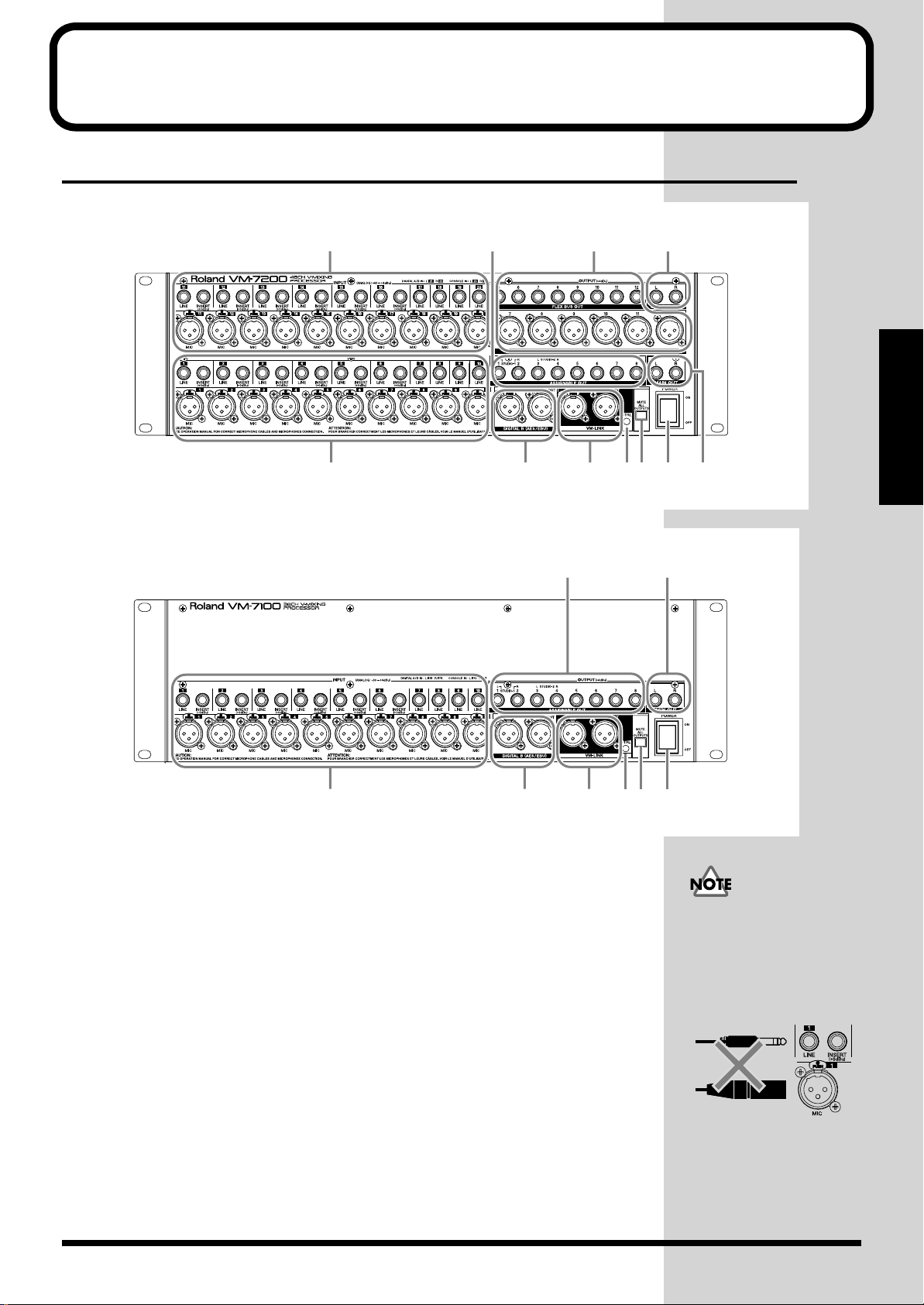
Front Panel
fig.2-01
811102
fig.2-02
1 INPUT 1–10
These are connectors for inputting analog audio signals to Channels 1–10. Connect
microphones, instruments, or other such equipment to these inputs (p. 27).
Microphones or other devices connected to the MIC connectors (XLR type) can be
supplied with electrical power at 48 volts DC (phantom power).
LINE: Used for connecting instruments and similar equipment (1/4” phone,
MIC: Used for connecting microphones and instruments with balanced output
INSERT:Used for inserting effects from external effects devices and similar
1 3 4 56 7
1 3 4 56 7
balanced or unbalanced)
(XLR type).
equipment into the inputs of Channels 1-6 (1/4” phone, TRS).
9
98
Do not have plugs
connected to both the MIC
connector and LINE jack
inputs for the same channel
simultaneously. Select one
or the other for use.
Front and Rear Panels
2 INPUT 11–20
These are connectors for inputting analog audio signals to Channels 11–20. Only the
VM-7200 is so equipped. Use just as you would INPUT 1–10.
9
Page 10

Front and Rear Panels
b
3 DIGITAL B (AES/EBU)
These are XLR-type digital audio input/output connectors. Use for connecting
professional digital devices and similar equipment (p. 29). These cannot be used
for inputting and outputting analog audio signals.
IN: Used for inputting digital audio signals. DIGITAL B IN cannot be used
when DIGITAL A IN is in use.
OUT: Used for outputting digital audio signals. Select the audio signals to be
output in the console’s patch bay (refer to the console Owner’s Manual).
4 VM-LINK
These are connectors used for inputting and outputting the mixing processor’s
control signals (VM-LINK). These connect to the mixing console (p. 23).
5 CTRL (Control)
This lights in green when the power is on. When VM-LINK data is being transmitted
between the processor and the mixing console, it flashes in green.
6 MUTE ALL OUTPUTS
Sound is prevented from being sent from all output connectors while the button is
held down (the sound is muted). Press this to prevent noise while inserting or
pulling out plugs (p. 25).
The red CTRL indicator
light indicates a problem in
transmitting VM-LINK
data. Check the connection
etween the processor and
the console.
7 POWER
This turns the power for the mixing console on and off.
8 ASSIGNABLE OUT
These are analog audio output jacks (1/4” phone, balanced/unbalanced). These
output the same sounds as those output from MULTI OUT 17–24 (R-BUS (RMDB2)).
9 MAIN OUT
These are connected to power amps and main speakers. These output the same
sounds as those output from MAIN OUT on the rear panel.
10 FLEX BUS OUT
These are analog audio output connectors and jacks assigned to the FLEX BUS (1/4”
phone, balanced/unbalanced; XLR type, balanced). Connect monitor speakers and
similar equipment to these connectors.
11 MONITOR OUT
These are connected to power amps and monitor speakers. Only the VM-7200 is so
equipped.
When the Bus mode is set to
INT, the signals on
FlexBuses 1–8 (5–8) are not
output from FLEX BUS
OUT (although you can
output the signals from
MASTER OUT and other
outputs). Refer to the
console Owner’s Manual.
10
Page 11
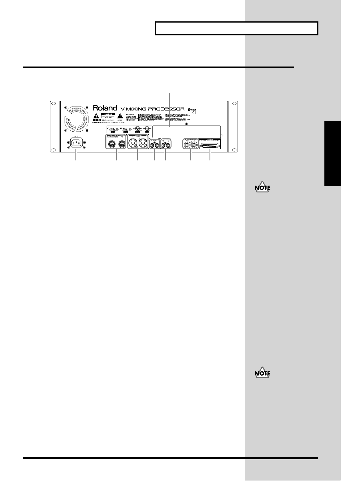
Rear Panel
fig.2-03
1234567
1 AC IN
Connect the power cord included with the processor.
2 MIDI/METER BRIDGE
Use these for connecting Roland’s MB-24 Meter Bridge, external MIDI devices (MIDI
controllers) and other devices.
OUT/THRU/METER: Use as a MIDI OUT or MIDI THRU connector. Ordinarily,
IN: MIDI messages are received here. Connect to the MIDI
Front and Rear Panels
8
Front and Rear Panels
Do not connect using any
power cord other than the
one provided. Using any
other power cord may
result in damage to the
equipment.
the MB-24 is connected.
OUT connector of an external MIDI device.
3 MAIN OUT
These are connected to power amps and main speakers. These output the same
sounds as those output from MAIN OUT on the front panel.
4 REC OUT
Usually a master recorder or consumer audio device (such as a radio cassette
recorder) is connected here.
5 DIGITAL A
These are coaxial type digital audio input/output connectors. Use for MD recorders
or DAT recorders (p. 29). These cannot be used for inputting and outputting
analog audio signals.
IN: Used for inputting digital audio signals. DIGITAL A IN cannot be used
OUT: Used for outputting digital audio signals. Select the audio signals to be
6 WORD CLOCK
These are connectors for input and output of the word clock used for synchronizing
external digital devices (BNC type) (p. 33).
IN: For inputting word clock.
OUT: For outputting word clock.
when DIGITAL B IN is in use.
output in the console’s patch bay (refer to the console Owner’s Manual).
Terminator settings are
required when word clock
is used. Refer to the console
Owner’s Manual.
11
Page 12

Front and Rear Panels
b
7 CASCADE
These are connectors used for a cascade connection of two mixing consoles (p. 32).
8 Rear Cover
A separately sold I/O expansion board VM-24E can be installed here (p. 14, 19)
In order to use the
CASCADE connector, you
must obtain the optional
Roland Cascade Kit
VM-24C.
VM-24C includes two
oards, a MASTER and a
SLAVE. Install the
MASTER board in one of
the processors, and the
SLAVE board in the other
processor (p. 16, 21).
12
Page 13

Installing Optional Devices
Cautions Concerning Installation of Optional Devices
• Always turn the unit off and unplug the power cord before attempting
installation of the circuit board (model no. VS8F-2, VM-24C, VM-24E; p. 26).
• Install only the specified circuit board(s) (model no. VS8F-2, VM-24C, VM24E). Remove only the specified screws (p. 13, 14, 16, 18, 19, 21).
• To avoid the risk of damage to internal components that can be caused by
static electricity, please carefully observe the following whenever you handle
the board.
• Before you touch the board, always first grasp a metal object (such as a
water pipe), so you are sure that any static electricity you might have been
carrying has been discharged.
• When handling the board, grasp it only by its edges. Avoid touching any
of the electronic components or connectors.
• Use a Phillips screwdriver of a size appropriate for the head of the screw (a
no.2 screwdriver). If the screwdriver is the wrong size, the screw heads may
be stripped, or you may not be able to turn the screws.
• To remove the screws, rotate the screwdriver counterclockwise. To tighten
the screws, rotate the screwdriver clockwise.
• Take care not to drop any screws into the interior of the VM-7000 series’
chassis.
• Do not touch any of the printed circuit pathways or connection terminals.
• Never use excessive force when installing a circuit board. If it doesn’t fit
properly on the first attempt, remove the board and try again.
• When circuit board installation is complete, double-check your work.
tightenloosen
Installing Optional Devices
Installing Effects Processors (VS8F-2)
The VM-7000 series comes with two onboard stereo effects processors. If you wish
to add more effects, Roland offers the VS8F-2 Effects Expansion Board, available for
separate purchase. Up to three of these effects expansion boards can be installed in
the VM-7000 series. If VS8F-2 boards are installed, you can use a maximum of nine
stereo effects on the VM-7000 series without using any external equipment. Roland
recommends that you install one or more VS8F-2 boards.
1 Turn off the power on all equipment, and disconnect all cables from the
VM-7000 series unit.
2 Remove only the screws specified in the following diagram, and detach the
top panel of the VM-7000 series unit.
fig.3-04_65
13
Page 14

Installing Optional Devices
b
3 There are three connectors and nine plastic pins inside. Insert the VS8F-2
connector into the internal connector, and at the same time, insert the
plastic pins into the holes of the VS8F-2 to firmly fix it in place.
fig.3-05_65
If you are installing only
one VS8F-2, connect it at
EFFECT A. If you are
installing two VS8F-2
oards, connect them at
EFFECT A and EFFECT B.
4 Using the (specified) screws you removed in step 2, reattach the top panel.
5 This completes installation of the VS8F-2.
Installing R-BUS (RMDB2) Connectors (VM-24E)
Roland also makes available the VM-24E I/O Expansion Board, which can be
purchased separately. When the VM-24E is installed, you can add three R-BUS
(RMDB2) connectors. By connecting a Roland DIF-AT, you can exchange 8-in/8-out
24-bit digital audio signals with a digital multitrack recorder, such as the ALESIS
adat or the TASCAM DA-88 (maximum of three recorders). Roland recommends
that you install the VM-24E.
1 Turn off the power on all equipment, and disconnect all cables from the
VM-7000 series unit.
2 Remove only the screws specified in the following diagram, and remove
the top panel and rear cover of the VM-7000 series unit.
fig.3-06_65
R-BUS, RMDB2 and RMDB II
are the same standard of
Roland.
14
Page 15

3 Insert the VM-24E connector into the internal connector, and
simultaneously insert the plastic pins into the holes of the VM-24E to fasten
it in place.
fig.3-07_65
Installing Optional Devices
4 Using the (specified) screws that you removed in step 2, attach the VM-24E
to the rear panel. Keep the rear cover in a safe place.
5 Using the (specified) screws you removed in step 2, reattach the top panel.
6 This completes installation of the VM-24E.
Installing Optional Devices
15
Page 16

Installing Optional Devices
b
Installing the Cascade Kit (VM-24C)
Roland also offers the VM-24C Cascade Kit, available for separate purchase. Once
the VM-24C is installed, you will be able to use the CASCADE connector. By
cascading two VM-7000 series units, a maximum of 94 input channels can be
supported (when the VM-24E and DIF-AT are used). Roland recommends that you
install the VM-24C.
1 Turn off the power on all equipment, and disconnect all cables from the
VM-7000 series unit.
2 Remove only the screws specified in the following diagram, and detach the
top panel of the VM-7000 series unit.
fig.3-04_65
The VM-24C includes two
oards, a MASTER and a
SLAVE. Install the
MASTER board in one of
the processors and the
SLAVE board in the other
processor.
The CASCADE
connectors cannot be
used unless both boards
are installed. (p. 32)
3 Insert the VM-24C connector into the internal connector, and
simultaneously insert the plastic pins into the holes of the VM-24C to fasten
it in place.
fig.3-09_65
The processor which
includes the SLAVE board
of the VM-24C cascade kit
does not work as a master
unit in the single processor
configuration. (p. 32)
If you wish, please take the
SLAVE board off the
processor.
4 Using the (specified) screws you removed in step 2, reattach the top panel.
5 This completes installation of the VM-24C.
16
Page 17

Installing Optional Devices
Changing the Rack-mount Hardware (RO-7000)
The VM-7000 series comes with pre-installed rack-mount brackets that allow the
unit to be mounted in a system rack. As a separately sold option, a different set of
rack-mount brackets — the RO-7000 — is available for purchase. When the RO-7000
is installed, the VM-7000 series will be positioned slightly backward (away from
yourself) in the rack. This way, cable connectors that are plugged into the front panel
jacks will not be in the way.
1 Turn off the power on all equipment, and disconnect all cables from the
VM-7000 series unit.
2 Remove only the screws shown in the following diagram, and detach the
rack-mount brackets that came with your VM-7000 series unit.
fig.3-10
3 Using the (specified) screws that you removed in step 2, attach the
RO-7000.
fig.3-11
4 This completes installation of the RO-7000.
Installing Optional Devices
There are two ways to
attach the RO-7000. Use the
method suitable for your
needs.
17
Page 18

Installation de dispositifs optionnels
Précautions à prendre lors de l’installation de dispositifs optionnels
• Toujours éteindre et débrancher l’appareil avant de commencer l’installation
de la carte. (modèle no VS8F-1, VM-24E, VM-24C; p. 26).
•
N’installez que les cartes de circuits imprimes spécifiées (modèle no VS8F-2,
VM-24E, VM-24C). Enlevez seulement les vis indiquées (p. 13, 14, 16, 18, 19, 21).
• Veuillez suivre attentivement les instructions suivantes quand vous
manipulez la carte afin d’éviter tout risque d’endommagement des pièces
internes par l’électricité statique.
•Toujours toucher un objet métallique relié à la terre (comme un tuyau par
exemple) avant de manipuler la carte pour vous décharger de l’électricité
statique que vous auriez pu accumuler.
•Lorsque vous manipulez la carte, la tenir par les côtés. Évitez de toucher
aux composants ou aux connecteurs.
• Utiliser un tournevis cruciforme correspondant à la taille de la vis (un
tournevis numéro 2). En cas d’utilisation d’un tournevis inapproprié, la tête
de la vis pourrait être endommagée.
• Pour enlever les vis, tourner le tournevis dans le sens contraire des aiguilles
d’une montre. Pour resserrer, tourner dans le sens des aiguilles d’une
montre.
• Veillez à ne pas laisser tomber de vis dans le châssis du VM-7000.
• Ne pas toucher aux circuits imprimés ou aux connecteurs.
• Ne jamais forcer lors de l’installation de la carte de circuits imprimés. Si la
carte s’ajuste mal au premier essai, enlevez la carte et recommencez
l’installation.
• Quand l’installation de la carte de circuits imprimés est terminée, revérifiez
si tout est bien installé.
resserrerdesserrer
Installation d’un processeur à effet (VS8F-2)
La série VM-7000 possède deux processeurs à effet stéréo. Si vous désirez ajouter
plus d’effets, Roland propose séparément la carte d’extension à effet VS8F-2.
Jusqu’à trois de ces cartes peuvent être installées dans le VM-7000. Si des cartes
VS8F-2 sont installées, vous pouvez utiliser un maximum de huit effets stéréo sur le
VM-7000 sans vous servir d’aucun équipement externe. Roland vous recommande
d’installer une ou plusieurs cartes VS8F-2.
1 Éteindre l’appareil et déconnecter tous les câbles du VM-7000.
2 N’enlever que les vis spécifiées sur le schéma suivant et détacher la plaque
du dessus du VM-7000.
fig.3-04_65
18
Page 19

Installation de dispositifs optionnels
3 Il y a trois connecteurs et neuf broches en plastique à l’intérieur. Insérer
simultanément le connecteur du VS8F-2 dans le connecteur interne et les
broches en plastique dans les trous du VS8F-2 pour le fixer fermement.
fig.3-05_65
Si vous installez seulement
une carte VS8F-2, la
connecter à EFFET A. Si
vous installez deux cartes
VS8F-2, les connecter à
EFFET A et EFFET B.
4 Utiliser les vis enlevées à l’étape 2 pour fixer à nouveau la plaque du
dessus.
5 Ceci complète l’installation du VS8F-2.
Installation d’un connecteur (VM-24E) R-BUS (RMDB2)
Roland propose aussi une carte d’extension VM-24E I/O que vous pouvez acheter
séparément. Quand le VM-24E est installé, vous pouvez ajouter trois connecteurs RBUS (RMDB2). En connectant le DIF-AT Roland, vous pouvez échanger des signaux
audio digitaux 24 bit 8 entrées/8 sorties avec un enregistreur digital multi-pistes
comme le ALESIS adat ou le TASCAM DA-88 (maximum de 3 enregistreurs).
Roland vous recommande d’installer le VM-24E.
1 Éteindre l’appareil et déconnecter tous les câbles du VM-7000.
2 N’enlever que les vis spécifiées sur le schéma suivant et détacher la plaque
du dessus et la plaque arrière du VM-7000.
fig.3-06_65
Installation de dispositifs optionnels
19
Page 20

Installation de dispositifs optionnels
3 Insérer simultanément le connecteur du VM-24E dans le connecteur interne
et les broches en plastique dans les trous du VM-24E pour le fixer
fermement.
fig.3-07_65
4 Utiliser les vis enlevées à l’étape 2 et fixer le VM-24E à la plaque arrière.
Conserver la plaque arrière dans un endroit sûr.
5 Utiliser les vis enlevées à l’étape 2 pour fixer à nouveau la plaque du
dessus.
6 Ceci complète l’installation du VM-24E.
20
Page 21

Installation de dispositifs optionnels
Installation d’un kit Cascade (VM-24C)
Roland propose aussi séparément le kit Cascade (VM-24C). Une fois le VM-24C
installé, vous serez en mesure d’utiliser le connecteur CASCADE. En connectant en
cascade deux unités de la série VM-7000, vous pourrez utiliser un maximum de 94
canaux d’entrée (lorsque le VM-24E et le DIF-AT sont utilisés). Roland vous
recommande d’installer un VM-24C.
1 Éteindre l’appareil et déconnecter tous les câbles du VM-7000.
2 N’enlever que les vis spécifiées sur le schéma suivant et détacher la plaque
du dessus du VM-7000.
fig.3-04_65
Il est impossible d’utiliser
le connecteur CASCADE si
le VM-24C n’est pas
installé. (p. 32)
3 Insérer simultanément le connecteur du VM-24C dans le connecteur
interne et les broches en plastique dans les trous du VM-24C pour le fixer
fermement.
fig.3-09_65
4 Utiliser les vis enlevées à l’étape 2 pour fixer à nouveau la plaque du
dessus.
Installation de dispositifs optionnels
5 Ceci complète l’installation du VM-24C.
21
Page 22

Installation de dispositifs optionnels
Changement du matériel de montage en rack (RO-7000)
La série VM-7000 est fournie avec des supports pré-installés en rack qui permettent
à l’appareil d’être monté dans un rack. Un différent ensemble de supports
(RO-7000) est vendu en option. Quand le RO-7000 est installé, le VM-7000 sera
positionné légèrement vers l’arrière (éloigné de vous) dans le rack. Ainsi, les
connecteurs de câbles qui sont branchés dans les fiches de la plaque avant ne
gêneront pas.
1 Éteindre l’appareil et déconnecter tous les câbles du VM-7000.
2 N’enlever que les vis spécifiées sur le schéma suivant et détacher les
supports de rack fournis avec votre VM-7000.
fig.3-10
3 Utiliser les vis enlevées à l’étape 2 et fixer le RO-7000.
fig.3-11
4 Ceci complète l’installation du RO-7000.
Il y a deux façons de fixer le
RO-7000. Utiliser la
méthode qui vous convient
le mieux.
22
Page 23

Basic Connections
Connecting to the Console (VM-LINK)
The VM-7200 (VM-7100) connects to Roland mixing consoles (VM-C7200,
VM-C7100). Use the VM-LINK cable (AES/EBU digital audio cable) included with
the unit.
■ Connecting to the VM-C7200
fig.4-01e
To prevent malfunction
and/or damage to speakers
or other devices, always
turn down the volume, and
turn off the power on all
devices before making any
connections.
VM-LINK
to AC Power Outlet
Console (VM-C7200)
to AC Power Outlet
Processor (VM-7200)
Basic Connections
R
L
Power Amp & Speaker Stereo Set, etc.
If using headphones, connect the headphones to the VM-C7200’s PHONES jack.
L
R
23
Page 24

Basic Connections
■ Connecting to the VM-C7100
fig.4-02e
To prevent malfunction
and/or damage to speakers
or other devices, always
turn down the volume, and
turn off the power on all
devices before making any
connections.
VM-LINK
to AC Power Outlet
Console (VM-C7100)
to AC Power Outlet
Processor (VM-7200)
24
R
L
Power Amp & Speaker Stereo Set, etc.
If using headphones, connect the headphones to the VM-C7100’s PHONES jack.
L
R
Page 25

Turning On the Power
b
1 Switch on the POWER switch on the mixing processor (VM-7200,
VM-7100), and confirm that the CTRL indicator is lit.
fig.4-03e
Press "ON" (upper) side of the POWER switch.
2 Switch on the POWER switch on the mixing console (VM-C7200,
VM-C7100).
fig.4-04e
Press "ON" (right) side of the POWER switch.
3 Turn on the power to the audio devices (power amps, monitor speakers,
and other devices) connected to the mixing processor.
Basic Connections
Once the connections have
een completed (p. 23),
turn on power to your
various devices in the order
specified. By turning on
devices in the wrong order,
you risk causing
malfunction and/or
damage to speakers and
other devices.
Always make sure to have
the volume level turned
down before switching on
power. Even with the
volume all the way down,
you may still hear some
sound when the power is
switched on, but this is
normal, and does not
indicate a malfunction.
4 Raise the volume on the audio equipment to a suitable level.
■ Muting
Ordinarily, to prevent noise when turning the power on and off, or when plugging
in or unplugging microphones and instruments from the processor, the volume
levels on all devices are lowered.
However, when working in situations where it is difficult to lower the volume, such
as when the processor and console are separated, you can instead temporarily mute
the sound coming from the processor.
1 Press [MUTE ALL OUTPUTS] on the processor’s front panel. No sound is
output from the processor while the button is held down (the sound is
muted). At this time, CTRL lights in red.
fig.4-05e
CTRL lights in red.
While the button is held down, the sound is muted.
2 When you have finished connecting the microphone (or whatever it was
you needed to do), release [MUTE ALL OUTPUTS].
During start-up, the
processor’s CTRL indicator
lights in orange. CTRL
changes to green when the
processor has completed
start-up properly.
Begin the system
configuration check only
after you’ve confirmed that
the processor has started
up properly (CTRL is lit in
green). Refer to the console
Owner’s Manual.
Basic Connections
25
Page 26

Basic Connections
Turning Off the Power
1 Lower the volume on all devices.
2 Turn off the power to the audio devices.
3 If needed, record the current operating settings internally to the console or
to a memory card.
4 Press the mixing console (VM-C7200, VM-C7100) POWER switch to turn
the power off.
fig.4-06e
Press "OFF" (lower) side of the POWER switch.
5 Press the mixing processor (VM-7200, VM-7100) POWER switch to turn
the power off.
fig.4-07e
Press "OFF" (left) side of the POWER switch.
26
Page 27

Various Connection Setups
Connecting Microphones and Instruments (Analog Connection)
This section describes examples of connecting microphones and instruments to the
processor.
Precautions When Connecting Microphones
• The pin assignment for the each connectors is as shown below. Before
making any connections, make sure that this pin assignment is compatible
with that of all your other devices.
fig.5-01
• Howling could be produced depending on the location of microphones
relative to speakers. This can be remedied by:
1 Changing the orientation of the microphone(s).
2 Relocating microphone(s) at a greater distance from speakers.
3 Lowering volume levels.
• Carefully read the owner’s manual for the microphone you are using, and
unless you are connecting a condenser mic requiring phantom power, be
sure turn phantom power off (refer to the console Owner’s Manual).
Supplying phantom power to dynamic microphones or keyboards may
result in damage to the equipment.
• Turn the phantom power on or off only after muting the channels to which
condenser microphones are connected. A loud noise or pop is produced
when the phantom power is turned on or off without muting first, and this
noise can severely damage amps, speakers, or other equipment.
When the console and
processor are separated,
hold down
[MUTE ALL OUTPUTS] on
the processor.
1 Completely lower the console’s MASTER fader.
2 Select the channel to which you want to input the sound, and connect the
microphone or instrument to the corresponding INPUT jack.
fig.5-03e
Electronic Instruments, etc.Microphone
Do not have plugs
connected to both the MIC
connector and LINE jack
inputs for the same channel
simultaneously. Select one
or the other for use.
Various Connection Setups
Processor (VM-7200)
27
Page 28

Various Connection Setups
3 Raise the MASTER fader and the applicable channel fader.
■ Using External Effects (Insert)
Use the INSERT jacks when you want use an external effects device (Insert) to
process the sounds from microphones or instruments that are input to the channels,.
A branch cable must be obtained for this.
INSERT Jack Block Diagram is as shown below.
fig.5-05e
Phamtom Power (DC+48V)
MIC
Gain AD Converter
to Input Select
LINE
INSERT
1 Mute the channel that you want to process with effects (refer to the console
Owner’s Manual).
2 Connect the external effects device to the INSERT jack for the channel
selected in Step 1.
fig.5-06e
WhiteRed
Out In
External Effects Processor
INSERT jacks are used for
Channels 1–6 (Channels
11–16). In addition, the
MIC jacks and LINE jacks
can also be used for
connecting.
Processor (VM-7200)
3 Release the mute on the channel to be processed with effects, then raise the
MASTER fader and the applicable channel fader.
28
Page 29

Various Connection Setups
Connecting MD Recorders, CD Players, and Other Digital Devices (Digital Connection)
When you want to connect the processor to a professional DAT recorder, a consumer
MD or CD player, or other such digital device, use the DIGITAL connectors. First
obtain a connector cable compatible with the digital device you are using. Digital
audio signals input through the DIGITAL connectors are assigned to Channels 21/22.
1 Mute Channels 21/22 (refer to the console Owner’s Manual).
2 Connect to the output connector of the external digital device you are
using. When connecting to digital devices for professional use (with XLR
connectors), connect to DIGITAL B IN. When connecting to MD or CD
player, or other such digital device for consumer use (with coaxial
connectors), connect to DIGITAL A IN. However, DIGITAL A IN and
DIGITAL B IN cannot be used simultaneously.
fig.5-07e
When connecting digital
devices featuring optical
type connectors, it will be
necessary to obtain a
commercially available
optical/coaxial converter.
Digital Output Connector
MD Recorder
Processor (VM-7200)
DAT Recorder
Digital Output Connector
Coaxial Cable
AES/EBU Digital Audio Cable
3 Release the mute on Channels 21/22, then raise the MASTER fader and the
Channel 21/22 faders.
Various Connection Setups
29
Page 30

Various Connection Setups
Connecting the Roland DIF-AT (R-BUS (RMDB2) Connection)
Roland also makes available the VM-24E I/O Expansion Board, which can be
purchased separately. When the VM-24E is installed, you can add three R-BUS
(RMDB2) connectors (p. 14, 19). By connecting a Roland DIF-AT, you can exchange
8-in/8-out 24-bit digital audio signals with a digital multitrack recorder, such as the
ALESIS adat or the TASCAM DA-88 (maximum of three recorders).
■ Connecting the ALESIS adat
fig.5-08e
adat
DIF-AT
To prevent malfunction
and/or damage to speakers
or other devices, always
turn down the volume, and
turn off the power on all
devices before making any
connections.
SYNC
(IN or OUT)
Processor (VM-7200)
adat Optical
IN/OUT
R-BUS(RMDB2)
1 Use the R-BUS cable included with the DIF-AT to connect the DIF-AT and
the processor.
Connecting to the adat’s
SYNC IN connector the
adat in Sync Slave mode.
This setup enables the
transport controls to be
operated from the console.
2 Use an optical cable (sold separately) for use with adat to connect the adat
and the DIF-AT. Make the settings for the console (master or slave)
according to the connections used. Refer to the console Owner’s Manual and
DIF-AT Owner’s Manual.
3 Press the Mixing Processor (VM-7200, VM-7100) POWER switch to turn on
the power. Confirm that the DIF-AT’s POWER indicator is lit.
30
Connecting to the adat’s
SYNC OUT connector the
adat in Sync Master mode.
In this setup, the transport
controls cannot be operated
from the console.
Page 31

■ Connecting the TASCAM DA Series
fig.5-09e
Various Connection Setups
DIGITAL I/O
TDIF-1
TASCAM DA series
REMOTE IN /
SYNC IN
DIF-AT
R-BUS(RMDB2)
Processor (VM-7200)
1 Use the R-BUS cable included with the DIF-AT to connect the DIF-AT and
the processor.
2 Use a cable for use with TASCAM devices (sold separately) to connect the
TASCAM DA Series and the DIF-AT.
3 Press the Mixing Processor (VM-7200, VM-7100) POWER switch to turn on
the power. Confirm that the DIF-AT’s POWER indicator is lit.
Various Connection Setups
31
Page 32

Various Connection Setups
Connecting Two Processors (Cascade Connection)
Roland also offers the VM-24C Cascade Kit, available for separate purchase. Once
the VM-24C is installed, you will be able to use the CASCADE connector (p. 16, 21).
By cascading two VM-7000 series units, a maximum of 94 input channels can be
supported (when the VM-24E and DIF-AT are used). Roland recommends that you
install a VM-24C.
The VM-24C includes two boards, a MASTER and a SLAVE. Install the MASTER
board in one of the processors and the SLAVE board in the other processor (p. 16,
21). The CASCADE connectors cannot be used unless both boards are
installed.
fig.5-10e
Processor (SLAVE) Processor (MASTER)
To prevent malfunction
and/or damage to speakers
or other devices, always
turn down the volume, and
turn off the power on all
devices before making any
connections.
R-BUS(RMDB2)
VM-LINK
Console 1 Console 2
32
Page 33

1 Use the R-BUS cable included with the VM-24C to connect the two
processors.
2 Use the VM-LINK cable included with the console to connect the master
processor and the consoles. Be careful not to connect VM-LINK cable to
the slave processor.
* In console Owner’s Manual, the master processor is called the 1st UNIT and the
slave processor is called the 2nd UNIT.
3 Turn the POWER switch on each processor to ON.
4 Turn the POWER switch on each console to ON.
5 The processor with the MASTER board installed becomes the Cascade
connection master.
Connecting Word Clock
In cases such as when connecting multiple devices in a studio using digital
connections, a standardized signal for synchronization is needed so that the digital
audio for each device can be exchanged correctly. This synchronizing signal is
known as word clock. In general, a digital multitrack recorder or word clock
generator is used as the master, and a mixing processor (VM-7200, VM-7100) or other
digital device operates as the slave.
fig.5-11e
Processor (VM-7200)
Various Connection Setups
The processor which
includes the SLAVE board
of the VM-24C cascade kit
does not work as a master
unit in the single processor
configuration.
If you wish, please take the
SLAVE board off the
processor. (p. 16, 21)
To prevent malfunction
and/or damage to speakers
or other devices, always
turn down the volume, and
turn off the power on all
devices before making any
connections.
TASCAM DA series
WORD CLOCK
OUT
1 Use a word clock cable to connect the word clock master (in this example, a
digital multitrack recorder) and the processor.
2 Turn the POWER switch on the processor to ON.
3 Turn the POWER switch on the console to ON.
4 Set the processor to function as the word clock slave (refer to the console
Owner’s Manual for instructions).
The processors can
function as both word clock
master and slave (refer to
the console Owner’s
Manual).
Connection of the word
clock is not required when
using the Roland DIF-AT to
ALESIS adat or TASCAM
DA Series recorders (p. 30,
31).
33
Various Connection Setups
Page 34

Troubleshooting
If it appears that the VM-7200 or VM-7100 is not operating properly, check over the
suggested remedies below before assuming that the unit is experiencing a
malfunction. If after checking the following you find that the problem persists, call
Roland Information or consult your nearby Roland Service Center or Roland dealer.
No Sound
- Power to the processor, console, or other connected device has not been turned on.
- The VM-LINK cable is not properly connected (p. 23).
- An audio cable is not properly connected (p. 23).
- The volume level of a connected amp or speakers is turned down.
- Channel faders or Master faders are lowered.
- Channels are muted (p. 25).
- You are using a power cord other than the original cord provided with the
equipment.
→ Some third-party power cords, while resembling the original, may not make
secure electrical contact, resulting in poor operation. Be sure to use only the
power cord included with each device.
- The volume level of the instrument connected to Processor is too low.
→ Could you be using a connection cable that contains a resistor? Use a
connection cable that does not contain a resistor.
- A device that consumes large amounts of power is being used at the same time.
→ Other devices can cause a severe reduction in voltage. Use a separate electrical
outlet for any piece of equipment that consumes large amounts of electricity.
No Sound From Specific Channel
- The input sensitivity (pre amp gain) is too low.
- There is a discrepancy between the channel assigned to the channel fader and the
channel used for that sound.
- The Solo or Mute function is being used.
Sound is Noisy or Distorted
- The input sensitivity (pre amp gain) is not set properly.
→ Setting the input sensitivity too high distorts the sound; conversely, when the
input sensitivity is set too low, the sound becomes very noisy. Set the input
sensitivity so that the level meter fluctuates at as high a level as possible within
the range of -12 to 0 dB (refer to the console Owner’s Manual).
- A device producing noise (such as a computer or monitor) is set up near a
connected microphone.
- The equalizer is being used.
→ Some equalizer settings may cause the sound to become distorted. In such
cases, readjust the equalizer.
- The recording or playback pitch of a connected digital multitrack recorder (such
as an ALESIS adat or TASCAM DA) has been changed (the Vari-Pitch function has
been used).
→ The maximum sampling rate for the VM-7000 Series is 48 kHz. Thus, raising
the pitch with the Vari-Pitch function when the digital MTR’s Master Clock is
already running at 48 kHz can cause noise to be produced. In such cases, use
an analog connection for the audio signals.
34
Page 35

Effect Not Applied
- The VS8F-2 has not been installed in the processor (p. 13, 18).
- Channel effect send levels are lowered (refer to the console Owner’s Manual).
- The effect is already being inserted into another channel.
- You are trying to select an algorithm that cannot be used in the master effects.
- External effects are being used.
→ Check the INSERT jack block diagram, and reconnect the Send and Return
properly (p. 28).
Cannot Make Cascade Connection
-
The VM-24C has not been installed on both processors that are being connected (p. 16,
21).
- The R-BUS (RMDB2) cable included with the VM-24C is not being used (p. 32).
→ Although they look similar, SCSI cables and cables for TASCAM devices are
not compatible and cannot be used. Using other cables may result in damage
to the equipment; be sure to use the R-BUS (RMDB2) cable.
- The master and slave are not connected correctly (p. 32).
→ Sounds from the master processor cannot be output from the slave processor.
Use the processor with the VM24-C MASTER board installed as the master.
Troubleshooting
Cannot Connect Digital MTR (ALESIS adat, TASCAM DA, or Other)
- VM-24E has not been installed in the processor (p. 14, 19).
- The R-BUS (RMDB2) cable included with the DIF-AT is not being used (p. 30).
→ Although they look similar, SCSI cables and cables for TASCAM devices are
not compatible and cannot be used. Using other cables may result in damage
to the equipment; be sure to use the R-BUS (RMDB2) cable.
35
Troubleshooting
Page 36

MIDI Implementation
Model: VM-7100/VM-7200, Version 1.00, Jun. 25 1999
1. Transmitted Data and Recognized
Receive Data
■Channel Voice Message
●Polyphonic Key Pressure
Transmits the level meter value according to the value of “Level Meter Tx. via MIDI.”
When the spectrum analyzer was selected as the effect type, sends the level value at each
frequency band area.
Ignored when received.
Status Second Third
AnH mmH llH
n = MIDI Channel No.: 0H - FH (ch.1 - ch.16)
mm = Note No.: 00H - 27H (0 - 39) (*1)
ll = Level Meter Value: 00H - 36H (0 - 54) (*2)
Level Meter and Note No.
Level Meter Spectrum
Target Input MultiIn FlexBus MultiOut Analyzer Effects
Note Level Meter Level Meter Level Meter Level Meter Level Meter Level Meter
Number Channel Channel Channel Channel Channel Channel
0 Input 1 MultiIn 1 BUS 1 Assign Out 1 Analyzer 20 Hz FX1 Input Lch
1 Input 2 MultiIn 2 BUS 2 Assign Out 2 Analyzer 25 Hz FX1 Input Rch
2 Input 3 MultiIn 3 BUS 3 Assign Out 3 Analyzer 31.5Hz FX1 Output Lch
3 Input 4 MultiIn 4 BUS 4 Assign Out 4 Analyzer 40 Hz FX1 Output Rch
4 Input 5 MultiIn 5 BUS 5 Assign Out 5 Analyzer 50 Hz FX2 Input Lch
5 Input 6 MultiIn 6 BUS 6 Assign Out 6 Analyzer 63 Hz FX2 Input Rch
6 Input 7 MultiIn 7 BUS 7 Assign Out 7 Analyzer 80 Hz FX2 Output Lch
7 Input 8 MultiIn 8 BUS 8 Assign Out 8 Analyzer 100 Hz FX2 Output Rch
8 Input 9 MultiIn 9 BUS 9 Assign Out 9 Analyzer 125 Hz FX3 Input Lch
9 Input 10 MultiIn 10 BUS 10 Assign Out 10 Analyzer 160 Hz FX3 Input Rch
10 Input 11 MultiIn 11 BUS 11 Assign Out 11 Analyzer 200 Hz FX3 Output Lch
11 Input 12 MultiIn 12 BUS 12 Assign Out 12 Analyzer 250 Hz FX3 Output Rch
12 Input 13 MultiIn 13 - Assign Out 13 Analyzer 315 Hz FX4 Input Lch
13 Input 14 MultiIn 14 - Assign Out 14 Analyzer 400 Hz FX4 Input Rch
14 Input 15 MultiIn 15 - Assign Out 15 Analyzer 500 Hz FX4 Output Lch
15 Input 16 MultiIn 16 - Assign Out 16 Analyzer 630 Hz FX4 Output Rch
16 Input 17 MultiIn 17 - Assign Out 17 Analyzer 800 Hz FX5 Input Lch
17 Input 18 MultiIn 18 - Assign Out 18 Analyzer 1.0kHz FX5 Input Rch
18 Input 19 MultiIn 19 - Assign Out 19 Analyzer 1.2kHz FX5 Output Lch
19 Input 20 MultiIn 20 - Assign Out 20 Analyzer 1.6kHz FX5 Output Rch
20 Input 21 MultiIn 21 - Assign Out 21 Analyzer 2.0kHz FX6 Input Lch
21 Input 22 MultiIn 22 - Assign Out 22 Analyzer 2.5kHz FX6 Input Rch
22 Input 23 MultiIn 23 - Assign Out 23 Analyzer 3.2kHz FX6 Output Lch
23 Input 24 MultiIn 24 - Assign Out 24 Analyzer 4.0kHz FX6 Output Rch
24 - - - - Analyzer 5.0kHz FX7 Input Lch
25 - - - - Analyzer 6.3kHz FX7 Input Rch
26 - - - - Analyzer 8.0kHz FX7 Output Lch
27 - - - - Analyzer 10 kHz FX7 Output Rch
28 - - - - Analyzer 12 kHz FX8 Input Lch
29 - - - - Analyzer 16 kHz FX8 Input Rch
30 - - - - Analyzer 20 kHz FX8 Output Lch
31 - - - - Analyzer Input FX8 Output Rch
32 MONITOR Lch MONITOR Lch MONITOR Lch MONITOR Lch MONITOR Lch MONITOR Lch
33 MONITOR Rch MONITOR Rch MONITOR Rch MONITOR Rch MONITOR Rch MONITOR Rch
34 MASTER Lch MASTER Lch MASTER Lch MASTER Lch MASTER Lch MASTER Lch
35 MASTER Rch MASTER Rch MASTER Rch MASTER Rch MASTER Rch MASTER Rch
36 - - - - - MST FX Input Lch
37 - - - - - MST FX Input Rch
38 - - - - - MST FX Output Lch
39 - - - - - MST FX Output Rch
40 - - - - - 41 - - - - - 42 - - - - - 43 - - - - - 44 - - - - - 45 - - - - - 46 - - - - - 47 - - - - - -
Level Meter Value and Level
Level Meter / Spectrum Analyzer
Value Level
0 0 dB
1 -1 dB
2 -2 dB
:
127 -∞ dB
●Control Change
Parameters on the Mixer section can be received and transmitted by the control change
messages when the VM-Link is connected and moreover “MIDI Control Type (*1)” in the
SYSTEM parameter is set to “C.C.”
When the VM-Link is not connected and moreover the “MIDI Control Type (*1)” is set to
“C.C.” or “NRPN,” the message can be received.
Status Second Third
BnH mmH llH
n = MIDI Channel No.: 0H - FH (ch.1 - ch.16; see below)
mm = Mixer Parameter No.: (see below)
ll = Mixer Parameter Value: 00H - 7FH (0 - 127) (*1)
When “MIDI C.C. Type (*1)” in the SYSTEM parameter is set to “Mono”
When “MIDI Control Type (*1)” in the SYSTEM parameter is set to “C.C.,” Level
parameter/Switch parameter/Pan parameter of the MIXER parameter were transmitted
and received according to the “MIDI Control Change Type Assign” and “MIDI Control
Change Channel Assign” setting in the SYSTEM parameter.
The transmitted MIDI channel is set by the “MIDI Control Channel (*1)” in the VM-7200/
7100.
Mixer Parameter and MIDI Channel/Control Change No. default value
<Channel Strip>
C.C.# Control Parameter C.C.# Control Parameter
0 ---------------------------- 64 Input 6 Main Sw
1 Input 1 Main Level 65 Input 7 Main Sw
2 Input 2 Main Level 66 Input 8 Main Sw
3 Input 3 Main Level 67 Input 9 Main Sw
4 Input 4 Main Level 68 Input 10 Main Sw
5 Input 5 Main Level 69 Input 11 Main Sw
6 Input 6 Main Level 70 Input 12 Main Sw
7 Input 7 Main Level 71 Input 13 Main Sw
8 Input 8 Main Level 72 Input 14 Main Sw
9 Input 9 Main Level 73 Input 15 Main Sw
10 Input 10 Main Level 74 Input 16 Main Sw
11 Input 11 Main Level 75 Input 17 Main Sw
12 Input 12 Main Level 76 Input 18 Main Sw
13 Input 13 Main Level 77 Input 19 Main Sw
14 Input 14 Main Level 78 Input 20 Main Sw
15 Input 15 Main Level 79 Input 21 Main Sw
16 Input 16 Main Level 80 Input 22 Main Sw
17 Input 17 Main Level 81 Input 23 Main Sw
18 Input 18 Main Level 82 Input 24 Main Sw
19 Input 19 Main Level 83 MultiIn 1 Main Sw
20 Input 20 Main Level 84 MultiIn 2 Main Sw
21 Input 21 Main Level 85 MultiIn 3 Main Sw
22 Input 22 Main Level 86 MultiIn 4 Main Sw
23 Input 23 Main Level 87 MultiIn 5 Main Sw
24 Input 24 Main Level 88 MultiIn 6 Main Sw
25 MultiIn 1 Main Level 89 MultiIn 7 Main Sw
26 MultiIn 2 Main Level 90 MultiIn 8 Main Sw
27 MultiIn 3 Main Level 91 MultiIn 9 Main Sw
28 MultiIn 4 Main Level 92 MultiIn 10 Main Sw
29 MultiIn 5 Main Level 93 MultiIn 11 Main Sw
30 MultiIn 6 Main Level 94 MultiIn 12 Main Sw
31 MultiIn 7 Main Level 95 MultiIn 13 Main Sw
32 ---------------------------- 96 --------------------------- 33 MultiIn 8 Main Level 97 --------------------------- 34 MultiIn 9 Main Level 98 --------------------------- 35 MultiIn 10 Main Level 99 --------------------------- 36 MultiIn 11 Main Level 100 --------------------------- 37 MultiIn 12 Main Level 101 --------------------------- 38 MultiIn 13 Main Level 102 MultiIn 14 Main Sw
39 MultiIn 14 Main Level 103 MultiIn 15 Main Sw
40 MultiIn 15 Main Level 104 MultiIn 16 Main Sw
41 MultiIn 16 Main Level 105 MultiIn 17 Main Sw
42 MultiIn 17 Main Level 106 MultiIn 18 Main Sw
43 MultiIn 18 Main Level 107 MultiIn 19 Main Sw
44 MultiIn 19 Main Level 108 MultiIn 20 Main Sw
45 MultiIn 20 Main Level 109 MultiIn 21 Main Sw
46 MultiIn 21 Main Level 110 MultiIn 22 Main Sw
47 MultiIn 22 Main Level 111 MultiIn 23 Main Sw
48 MultiIn 23 Main Level 112 MultiIn 24 Main Sw
49 MultiIn 24 Main Level 113
50 Bus 1 Master Level 114
51 Bus 2 Master Level 115
52 Bus 3 Master Level 116
53 Bus 4 Master Level 117
54 Bus 5 Master Level 118
55 Bus 6 Master Level 119
56 Bus 7 Master Level 120 --------------------------- 57 Bus 8 Master Level 121 --------------------------- 58 Main Master Level 122 --------------------------- 59 Input 1 Main Sw 123 --------------------------- 60 Input 2 Main Sw 124 --------------------------- 61 Input 3 Main Sw 125 --------------------------- 62 Input 4 Main Sw 126 --------------------------- 63 Input 5 Main Sw 127 ----------------------------
36
Page 37

MIDI Implementation
❍ When the “MIDI C.C. Type (*1)” in the SYSTEM parameter is set to
“Multi”
When the “MIDI C.C. Type (*1)” is set to “Multi,” the MIXER parameters in the VM-7200/
7100 is transmitted and received through the multiple MIDI channels.
This function is used for controlling the Mixer section of the VM-7200/7100 or the GM
sound module.
Mixer Parameter and MIDI Channel/Control Change No.
<Channel Strip>
Input 1 2 3 4 5 6 7 8 9 10 11 12 13 14 15 16
MIDI channel 1 2 3 4 5 6 7 8 9 10 11 12 13 14 15 16
Master Fader Level 7 -> -> -> -> -> -> -> -> -> -> -> -> -> -> ->
Main Send Pan 10 -> -> -> -> -> -> -> -> -> -> -> -> -> -> ->
EQ L Freq. 12 -> -> -> -> -> -> -> -> -> -> -> -> -> -> ->
EQ L Gain 13 -> -> -> -> -> -> -> -> -> -> -> -> -> -> ->
EQ HM Freq. 14 -> -> -> -> -> -> -> -> -> -> -> -> -> -> ->
EQ HM Gain 15 -> -> -> -> -> -> -> -> -> -> -> -> -> -> ->
EQ HM Q 16 -> -> -> -> -> -> -> -> -> -> -> -> -> -> ->
EQ H Freq. 17 -> -> -> -> -> -> -> -> -> -> -> -> -> -> ->
EQ H Gain 18 -> -> -> -> -> -> -> -> -> -> -> -> -> -> ->
Bus1 Send Level 19 -> -> -> -> -> -> -> -> -> -> -> -> -> -> ->
Bus2 Send Level 20 -> -> -> -> -> -> -> -> -> -> -> -> -> -> ->
Bus3 Send Level 21 -> -> -> -> -> -> -> -> -> -> -> -> -> -> ->
Bus4 Send Level 22 -> -> -> -> -> -> -> -> -> -> -> -> -> -> ->
Bus5 Send Level 23 -> -> -> -> -> -> -> -> -> -> -> -> -> -> ->
Bus6 Send Level 24 -> -> -> -> -> -> -> -> -> -> -> -> -> -> ->
Bus7 Send Level 25 -> -> -> -> -> -> -> -> -> -> -> -> -> -> ->
Bus8 Send Level 26 -> -> -> -> -> -> -> -> -> -> -> -> -> -> ->
Input Mute Sw 27 -> -> -> -> -> -> -> -> -> -> -> -> -> -> ->
Input 17 18 19 20 21 22 23 24
MIDI channel 1 2 3 4 5 6 7 8
MIX Send Level 68 -> -> -> -> -> -> ->
MIX Send Pan/Bal 70 -> -> -> -> -> -> ->
EQ L Freq. 71 -> -> -> -> -> -> ->
EQ L Gain 72 -> -> -> -> -> -> ->
EQ HM Freq. 73 -> -> -> -> -> -> ->
EQ HM Gain 74 -> -> -> -> -> -> ->
EQ HM Q 75 -> -> -> -> -> -> ->
EQ H Freq. 76 -> -> -> -> -> -> ->
EQ H Gain 77 -> -> -> -> -> -> ->
Bus1 Send Level 78 -> -> -> -> -> -> ->
Bus2 Send Level 79 -> -> -> -> -> -> ->
Bus3 Send Level 80 -> -> -> -> -> -> ->
Bus4 Send Level 81 -> -> -> -> -> -> ->
Bus5 Send Level 82 -> -> -> -> -> -> ->
Bus6 Send Level 83 -> -> -> -> -> -> ->
Bus7 Send Level 84 -> -> -> -> -> -> ->
Bus8 Send Level 85 -> -> -> -> -> -> ->
Input Mute Sw 86 -> -> -> -> -> -> ->
MultiIn 1 2 3 4 5 6 7 8 9 10 11 12 13 14 15 16
MIDI channel 1 2 3 4 5 6 7 8 9 10 11 12 13 14 15 16
Main Send Level 39 -> -> -> -> -> -> -> -> -> -> -> -> -> -> ->
Main Send Pan 42 -> -> -> -> -> -> -> -> -> -> -> -> -> -> ->
EQ L Freq. 44 -> -> -> -> -> -> -> -> -> -> -> -> -> -> ->
EQ L Gain 45 -> -> -> -> -> -> -> -> -> -> -> -> -> -> ->
EQ HM Freq. 46 -> -> -> -> -> -> -> -> -> -> -> -> -> -> ->
EQ HM Gain 47 -> -> -> -> -> -> -> -> -> -> -> -> -> -> ->
EQ HM Q 48 -> -> -> -> -> -> -> -> -> -> -> -> -> -> ->
EQ H Freq. 49 -> -> -> -> -> -> -> -> -> -> -> -> -> -> ->
EQ H Gain 50 -> -> -> -> -> -> -> -> -> -> -> -> -> -> ->
Bus1 Send Level 51 -> -> -> -> -> -> -> -> -> -> -> -> -> -> ->
Bus2 Send Level 52 -> -> -> -> -> -> -> -> -> -> -> -> -> -> ->
Bus3 Send Level 53 -> -> -> -> -> -> -> -> -> -> -> -> -> -> ->
Bus4 Send Level 54 -> -> -> -> -> -> -> -> -> -> -> -> -> -> ->
Bus5 Send Level 55 -> -> -> -> -> -> -> -> -> -> -> -> -> -> ->
Bus6 Send Level 56 -> -> -> -> -> -> -> -> -> -> -> -> -> -> ->
Bus7 Send Level 57 -> -> -> -> -> -> -> -> -> -> -> -> -> -> ->
Bus8 Send Level 58 -> -> -> -> -> -> -> -> -> -> -> -> -> -> ->
MultiIn Mute Sw 59 -> -> -> -> -> -> -> -> -> -> -> -> -> -> ->
MultiIn 17 18 19 20 21 22 23 24
MIDI channel 1 2 3 4 5 6 7 8
MIX Send Level 102 -> -> -> -> -> -> ->
MIX Send Pan/Bal 103 -> -> -> -> -> -> ->
EQ L Freq. 104 -> -> -> -> -> -> ->
EQ L Gain 105 -> -> -> -> -> -> ->
EQ HM Freq. 106 -> -> -> -> -> -> ->
EQ HM Gain 107 -> -> -> -> -> -> ->
EQ HM Q 108 -> -> -> -> -> -> ->
EQ H Freq. 109 -> -> -> -> -> -> ->
EQ H Gain 110 -> -> -> -> -> -> ->
Bus1 Send Level 111 -> -> -> -> -> -> ->
Bus2 Send Level 112 -> -> -> -> -> -> ->
Bus3 Send Level 113 -> -> -> -> -> -> ->
Bus4 Send Level 114 -> -> -> -> -> -> ->
Bus5 Send Level 115 -> -> -> -> -> -> ->
Bus6 Send Level 116 -> -> -> -> -> -> ->
Bus7 Send Level 117 -> -> -> -> -> -> ->
Bus8 Send Level 118 -> -> -> -> -> -> ->
MultiIn Mute Sw 119 -> -> -> -> -> -> ->
<Talk Back Section> MIDI channel = 9
Talk Back Level 68
Talk Back To Main 70
Talk Back To Bus1 78
Talk Back To Bus2 79
Talk Back To Bus3 80
Talk Back To Bus4 81
Talk Back To Bus5 82
Talk Back To Bus6 83
Talk Back To Bus7 84
Talk Back To Bus8 85
Talk Back Sw 86
<Slate Section> MIDI channel = 10
Slate Level 68
Slate To Main 70
Slate To Bus1 78
Slate To Bus2 79
Slate To Bus3 80
Slate To Bus4 81
Slate To Bus5 82
Slate To Bus6 83
Slate To Bus7 84
Slate To Bus8 85
Slate Sw 86
Bus Number Bus1 Bus2 Bus3 Bus4 Bus5 Bus6 Bus7 Bus8
MIDI channel 12 13 14 15 12 13 14 15
Bus Master Level 68 -> -> -> 102 -> -> ->
Bus Return Pan 70 -> -> -> 103 -> -> ->
<Main Master Block> MIDI ch.=16
Main Master Level 68
Main Master Balance 70
NRPN (MSB/LSB)
Status Second Third
BnH 62H llH
BnH 63H mmH
n = MIDI Channel No.: 0H - FH (ch.1 - ch.16)
mm = upper byte of the parameter number to be assigned with NRPN: 00H - 7FH (0 - 127)
ll = lower byte of the parameter number to be assigned with NRPN: 00H - 7FH (0 - 127)
This message is received at the following case.
When the VM-Link is not connected and moreover the “MIDI Control Type (*1)” is set to
“NRPN” and moreover the MIDI channel of this message is same as the “MIDI Control
Channel (*1).”
After received this message, it is memorized as the “None Registered Parameter Number.”
“None Registered Parameter Number” value is equal to the “Start Address” referred in “2.
Address Map for Data Transfer” section.”
The address value range of “None Registered Parameter Number” is “00 00 00 - 00 7F 7F.”
See “2. Address Map for Data Transfer” section.
This message is transmitted at the following case.
When the VM-Link is connected and moreover the “MIDI Control Type (*1)” is set to
“NRPN” and moreover a parameter is modified.
MIDI Implementation
37
Page 38

MIDI Implementation
This message is transmitted with the MIDI channel set at the “MIDI Control Channel (*1).”
“None Registered Parameter Number” value is equal to the “Start Address” referred in “2.
Address Map for Data Transfer” section.”
The address value range of “None Registered Parameter Number” is “00 00 00 - 00 7F 7F.”
(*1) See “2. Address Map for Data Transfer” section.
❍Data Entry (MSB/LSB)
Status Second Third
BnH 06H mmH
BnH 26H llH
n = MIDI Channel No.: 0H - FH (ch.1 - ch.16)
mm = upper byte corresponding to the parameter assigned with NRPN
ll = lower byte corresponding to the parameter assigned with NRPN
<Ex> mmH llH = 40H 00H = -8192
= 7FH 7FH = -1
= 00H 00H = 0
= 3FH 7FH = +8191
This message is received at the following case.
When the “MIDI Control Type (*1)” parameter is set to “NRPN” and moreover the MIDI
channel value with the message is same as the “MIDI Control Channel (*1).”
After this message is received, the parameter is modified referring to the “None Registered
Parameter Number.”
When the “None Registered Parameter Number” is not set, this message was ineffective.
The setting value range of each parameter number is different.
See “2. Address Map for Data Transfer” section.
This message is transmitted at the following case.
When the VM-Link is not connected and moreover “MIDI Control Type (*1)” is set to
“NRPN” and moreover the parameter is modified.
This message is transmitted with the MIDI channel set as “MIDI Control Channel (*1).”
(*1) See “2. Address Map for Data Transfer” section.
❍Data Increment
When the VM-Link is not connected and moreover the “MIDI Control Type (*1)” parameter
is set to “NRPN” and moreover the MIDI channel value is same as the “MIDI Control
Channel (*1)” value.
After this message was received, the parameter is increased referring to the “None
Registered Parameter Number.”
The VM-7200/7100 doesn’t transmit this message.
Status Second Third
BnH 60H 00H
n = MIDI Channel No.: 0H - FH (ch.1 - ch.16)
Increment the effect parameter selected with NRPN.
(*1) See “2. Address Map for Data Transfer” section.
❍Data Decrement
When the VM-Link is not connected and moreover the “MIDI Control Type (*1)” parameter
is set to “NRPN” and moreover the MIDI channel value is same as the “MIDI Control
Channel (*1)” value.
After this message was received, the parameter is decreased referring to the “None
Registered Parameter Number.”
The VM-7200/7100 doesn’t transmit this message.
Status Second Third
BnH 61H 00H
n = MIDI Channel No.: 0H - FH (ch.1 - ch.16)
Decrement the effect parameter selected with NRPN.
(*1) See “2. Address Map for Data Transfer” section.
●Pitch bend Change
Status Second Third
EnH llH mmH
n = MIDI Channel No.: 0H - FH (ch.1 - ch.16)
mm, ll = Pitch Bend Value: 00 00H – 40 00H – 7F 7FH (-8192 – 0 – +8191)
Set the pitch bend value of third byte to the parameter which is designated with the MIDI
channel number and the pitch bend value of the second byte.
Parameters and Pitch bend Messages
Message Parameter Contents and remarks
------------------------------------------------------------------------- E0H 00H mmH Input Master Fader Level - CH 1
: : (Cascade Master Unit)
: :
E0H 2FH mmH MultiIn Master Fader Level - CH 24
------------------------------------------------------------------------- E0H 30H mmH Main Master Level
: : (Cascade Master Unit)
------------------------------------------------------------------------- E0H 31H mmH Input Main Send Pan - CH 1
: : (Cascade Master Unit)
: :
E0H 60H mmH MultiIn Main Send Pan - CH 24
------------------------------------------------------------------------- E0H 61H mmH Main Master Balance
: : (Cascade Master Unit)
------------------------------------------------------------------------- E0H 62H mmH Pre Amp Input Gain - CH1
: : (Cascade Master Unit)
E0H 79H mmH Pre Amp Input Gain - CH24
------------------------------------------------------------------------- E0H 7AH mmH (Reserved)
------------------------------------------------------------------------- E1H 00H mmH Input Bus 1 Send Level - CH1
: : (Cascade Master Unit)
: :
E1H 2FH mmH MultiIn Bus 1 Send Level - CH24
------------------------------------------------------------------------- E1H 30H mmH Input Bus 2 Send Level - CH1
: : (Cascade Master Unit)
: :
E1H 5FH mmH MultiIn Bus 2 Send Level - CH24
------------------------------------------------------------------------- E1H 60H mmH Input Bus 3 Send Level - CH1
: : (Cascade Master Unit)
: :
E2H 0FH mmH MultiIn Bus 3 Send Level - CH24
------------------------------------------------------------------------- E2H 10H mmH Input Bus 4 Send Level - CH1
: : (Cascade Master Unit)
: :
E2H 3FH mmH MultiIn Bus 4 Send Level - CH24
------------------------------------------------------------------------- E2H 40H mmH Input Bus 5 Send Level - CH1
: : (Cascade Master Unit)
: :
E2H 6FH mmH MultiIn Bus 5 Send Level - CH24
------------------------------------------------------------------------- E2H 70H mmH Input Bus 6 Send Level - CH1
: : (Cascade Master Unit)
: :
E3H 1FH mmH MultiIn Bus 6 Send Level - CH24
------------------------------------------------------------------------- E3H 20H mmH Input Bus 7 Send Level - CH1
: : (Cascade Master Unit)
: :
E3H 4FH mmH MultiIn Bus 7 Send Level - CH24
------------------------------------------------------------------------- E3H 50H mmH Input Bus 8 Send Level - CH1
: : (Cascade Master Unit)
: :
E3H 7FH mmH MultiIn Bus 8 Send Level - CH24
------------------------------------------------------------------------- E4H 00H mmH Input Bus 9 Send Level - CH1
: : (Cascade Master Unit)
: :
E4H 2FH mmH MultiIn Bus 9 Send Level - CH24
------------------------------------------------------------------------- E4H 30H mmH Input Bus 10 Send Level - CH1
: : (Cascade Master Unit)
38
Page 39

MIDI Implementation
: :
E4H 5FH mmH MultiIn Bus 10 Send Level - CH24
--------------------------------------------------------------------------
E4H 60H mmH Input Bus 11 Send Level - CH1
: : (Cascade Master Unit)
: :
E5H 0FH mmH MultiIn Bus 11 Send Level - CH24
--------------------------------------------------------------------------
E5H 10H mmH Input Bus 12 Send Level - CH1
: : (Cascade Master Unit)
: :
E5H 3FH mmH MultiIn Bus 12 Send Level - CH24
--------------------------------------------------------------------------
E5H 40H mmH Bus Master Fader Level - BUS1
: : (Cascade Master Unit)
E5H 4BH mmH Bus Master Fader Level - BUS12
--------------------------------------------------------------------------
E5H 4CH mmH (Reserved)
: :
--------------------------------------------------------------------------
E8H 00H mmH Input Master Fader Level - CH 1
: : (Cascade Slave Unit)
: :
E8H 2FH mmH MultiIn Master Fader Level - CH 24
--------------------------------------------------------------------------
E8H 30H mmH Main Master Level
: : (Cascade Slave Unit)
--------------------------------------------------------------------------
E8H 31H mmH Input Main Send Pan - CH 1
: : (Cascade Slave Unit)
: :
E8H 60H mmH MultiIn Main Send Pan - CH 24
--------------------------------------------------------------------------
E8H 61H mmH Main Master Balance
: : (Cascade Slave Unit)
--------------------------------------------------------------------------
E8H 62H mmH Pre Amp Input Gain - CH1
: : (Cascade Slave Unit)
E8H 79H mmH Pre Amp Input Gain - CH24
--------------------------------------------------------------------------
E8H 7AH mmH (Reserved)
--------------------------------------------------------------------------
E9H 00H mmH Input Bus 1 Send Level - CH1
: : (Cascade Slave Unit)
: :
E9H 2FH mmH MultiIn Bus 1 Send Level - CH24
--------------------------------------------------------------------------
E9H 30H mmH Input Bus 2 Send Level - CH1
: : (Cascade Slave Unit)
: :
E9H 5FH mmH MultiIn Bus 2 Send Level - CH24
--------------------------------------------------------------------------
E9H 60H mmH Input Bus 3 Send Level - CH1
: : (Cascade Slave Unit)
: :
EAH 0FH mmH MultiIn Bus 3 Send Level - CH24
--------------------------------------------------------------------------
EAH 10H mmH Input Bus 4 Send Level - CH1
: : (Cascade Slave Unit)
: :
EAH 3FH mmH MultiIn Bus 4 Send Level - CH24
--------------------------------------------------------------------------
EAH 40H mmH Input Bus 5 Send Level - CH1
: : (Cascade Slave Unit)
: :
EAH 6FH mmH MultiIn Bus 5 Send Level - CH24
--------------------------------------------------------------------------
EAH 70H mmH Input Bus 6 Send Level - CH1
: : (Cascade Slave Unit)
: :
EBH 1FH mmH MultiIn Bus 6 Send Level - CH24
--------------------------------------------------------------------------
EBH 20H mmH Input Bus 7 Send Level - CH1
: : (Cascade Slave Unit)
: :
EBH 4FH mmH MultiIn Bus 7 Send Level - CH24
--------------------------------------------------------------------------
EBH 50H mmH Input Bus 8 Send Level - CH1
: : (Cascade Slave Unit)
: :
EBH 7FH mmH MultiIn Bus 8 Send Level - CH24
------------------------------------------------------------------------- ECH 00H mmH Input Bus 9 Send Level - CH1
: : (Cascade Slave Unit)
: :
ECH 2FH mmH MultiIn Bus 9 Send Level - CH24
------------------------------------------------------------------------- ECH 30H mmH Input Bus 10 Send Level - CH1
: : (Cascade Slave Unit)
: :
ECH 5FH mmH MultiIn Bus 10 Send Level - CH24
------------------------------------------------------------------------- ECH 60H mmH Input Bus 11 Send Level - CH1
: : (Cascade Slave Unit)
: :
EDH 0FH mmH MultiIn Bus 11 Send Level - CH24
------------------------------------------------------------------------- EDH 10H mmH Input Bus 12 Send Level - CH1
: : (Cascade Slave Unit)
: :
EDH 3FH mmH MultiIn Bus 12 Send Level - CH24
------------------------------------------------------------------------- EDH 40H mmH Bus Master Fader Level - BUS1
: : (Cascade Slave Unit)
EDH 4BH mmH Bus Master Fader Level - BUS12
------------------------------------------------------------------------- EDH 4CH mmH (Reserved)
: :
--------------------------------------------------------------------------
■System Exclusive Message
Status Data Bytes Status
F0H iiH, ddH, ..., eeH F7H
Byte Description
F0H Status of System Exclusive Message
iiH Manufacturer ID
41H Roland’s Manufacturer ID
7EH Universal Non Realtime Message
7FH Universal Realtime Message
ddH Data : 00H - 7FH (0-127)
::
eeH Data
F7H EOX (End of System Exclusive Message)
The VM-7200/7100 can transfer and receive the internal parameters information using
system exclusive messages, and also can be controlled by the external devices using system
exclusive messages.
The VM-7200/7100 can transmit and receive the System Exclusive messages such as
Universal System Exclusive messages, Data Request (RQ1) and Data set (DT1).
❍About Model ID
For Data Request (RQ1) and Data Set (DT1), the VM-7200/7100 uses 00H 1EH as a Model
ID.
❍About Device ID
System Exclusive messages are not assigned to any particular MIDI channel.
Instead, they have their own special control parameter called device ID.
The Roland system exclusive messages use device IDs to specify multiple VM-7200/7100
units.
The VM-7200/7100 sends system exclusive messages using the value set at “MIDI System
Exclusive Device ID (*1),” and receives the system exclusive messages whose device ID is
same as its device ID and 7FH.
●Universal System Exclusive Message
❍INQUIRY MESSAGE
Identity Request
Status Data Byte Status
F0H 7EH, Dev, 06H, 01H F7H
Byte Description
F0H Status of System Exclusive Message
7EH Universal System Exclusive Message Non Realtime Header
Dev Device ID (or 7FH)
MIDI Implementation
39
Page 40

MIDI Implementation
06H General Information (sub ID #1)
01H Identify Request (sub ID #2)
F7H EOX (End of System Exclusive Message)
The message is used to request the particular information of the VM-7200/7100. If this
message is received right after the power is on, Device ID of the received message is set to
the Device ID of the VM-7200/7100.
If the first received message’s Device ID is 7FH, the VM-7200/7100’s Device ID is set to the
10H (cascade slave processor = 11H), default value.
The VM-7200/7100 does not transmit this message.
If the VM-7200/7100 received the message and the device ID of the received message is
same as its device ID or 7FH, the VM-7200/7100 transmits the following Identity Reply
message.
Status Data Bytes Status
F0H 7EH, Dev, 06H, 02H, 41H, 1EH, 01H, F7H
nnH, 00H, vvH, 00H, ssH, ssH
Byte Description
F0H Status of System Exclusive Message
7EH Universal System Exclusive Message Non Realtime Header
Dev Device ID
06H General Information (sub ID #1)
02H Identify Request (sub ID #2)
41H Manufacturer ID (Roland)
1EH 01H Device Family Code (VM-7200/7100)
nnH 00H Device Family No. (VM-xxxxx)
0:Reserved, 1:VM-7100, 2:VM-C7100, 3:VM-7200, 4:VM-C7200
vvH 00H Option Available No.
0 0 x x - x x x x
| | | | | +—— Effect Board A
| | | | +———— Effect Board B
| | | +—————— Effect Board C
| | +———————— R-BUS Board
| +———————————— Cascade Board
+—————————————— 7100/7200
ssH ssH Software Revision Level
F7H EOX (End of System Exclusive Message)
MIDI Machine Control Commands
Status Data Bytes Status
F0H 7FH, Dev, 06H, aaH, ..., bbH F7H
Byte Description
F0H Status of System Exclusive Message
7FH Universal System Exclusive Message Realtime Header
Dev Device ID (or 7FH)
06H MMC Command Message
aaH Command
::
bbH Command
F7H EOX (End of System Exclusive Message)
(*) see “3. MIDI Machine Control” section
MIDI Machine Control Responses
Status Data Bytes Status
F0H 7FH, Dev, 07H, aaH, ..., bbH F7H
Byte Description
F0H Status of System Exclusive Message
7FH Universal System Exclusive Message Realtime Header
Dev Device ID
07H MMC Response Message
aaH Response
::
bbH Response
F7H EOX (End of System Exclusive Message)
●Data Transfer (RQ1, DT1)
❍Data Request (RQ1)
Status Data Bytes Status
F0H 41H, Dev, 00H, 1EH, 11H, F7H
aaH, bbH, ccH, ssH, ssH, Sum
Byte Description
F0H Status of System Exclusive Message
41H Manufacturer ID (Roland)
Dev Device ID
00H 1EH Model ID (V-Mixer)
11H Command ID (RQ1)
aaH Address MSB
bbH Address MID
ccH Address LSB
ssH Size MSB
ssH Size MID
ssH Size LSB
Sum Check Sum
F7H EOX (End of System Exclusive Message)
The message is used to request data to the VM-7200/7100.
The VM-7200/7100 does not transmit this message.
The VM-7200/7100 transmits the requested data using Data Set (DT1) under following
condition when it received the message.
1 The requested address correspond to the specified parameter base address of the
VM-7200/7100.
2 The requested size is over 1 byte.
❍Data Set (DT1)
Status Data Bytes Status
F0H 41H, Dev, 00H, 0EH, 12H, F7H
aaH, bbH, ccH, ddH, ..., eeH, Sum
Byte Description
F0H Status of System Exclusive Message
41H Manufacturer ID (Roland)
Dev Device ID
00H 1EH Model ID (V-Mixer)
12H Command ID (DT1)
aaH Address MSB
bbH Address MID
ccH Address LSB
ddH Data
::
eeH Data
Sum Check Sum
F7H EOX (End of System Exclusive Message)
The message is received under the following condition.
If VM-Link is not connected, and the device ID on the message is same as that of the receive
device, and the address on the message correspond to the specified parameter base address,
the received data are stored from the specified parameter base address.
If the interval of received messages is shorter than 20 msec, the VM-7200/7100 can not work
the receive message procedure correctly.
The message is transmitted under the following condition.
When the VM-7200/7100 transmit the data on the requested parameter after receiving the
Data Request message (RQ1).
See “2. Data Transfer Address Map” for more details of the transfer parameters.
(*) see “3. MIDI Machine Control” section
40
Page 41

MIDI Implementation
2. Data Transfer Address Map
The each address value is expressed as a 7bit hex number.
+——————————————————————————————————————————————————————————————————+
| Address | MSB | MID | LSB |
|—————————————————————+——————————————+——————————————+——————————————+
| None Registered | 0000 0000 | 0mmm mmmm | 0lll llll |
| Parameter Number | 00 | MM | LL |
|—————————————————————+——————————————+——————————————+——————————————+
| Binary | 0aaa aaaa | 0bbb bbbb | 0ccc cccc |
| 7 Bit Hex | AA | BB | CC |
+——————————————————————————————————————————————————————————————————+
■MIDI Data - Mixer EQ Freq Table
+——————+————————++——————+————————++——————+————————++——————+————————+
| Data |Freq(Hz)|| Data |Freq(Hz)|| Data |Freq(Hz)|| Date |Freq(Hz)|
+——————+————————++——————+————————++——————+————————++——————+————————+
| 00H | 16.0 || 20H | 100 || 40H | 630 || 60H | 4.00k |
| 01H | 17.0 || 21H | 106 || 41H | 670 || 61H | 4.22k |
| 02H | 18.0 || 22H | 112 || 42H | 710 || 62H | 4.50k |
| 03H | 19.0 || 23H | 120 || 43H | 750 || 63H | 4.73k |
| 04H | 20.0 || 24H | 125 || 44H | 800 || 64H | 5.00k |
| 05H | 21.0 || 25H | 133 || 45H | 840 || 65H | 5.30k |
| 06H | 22.4 || 26H | 140 || 46H | 900 || 66H | 5.60k |
| 07H | 23.7 || 27H | 150 || 47H | 944 || 67H | 6.00k |
| 08H | 25.0 || 28H | 160 || 48H | 1.00k || 68H | 6.30k |
| 09H | 26.6 || 29H | 170 || 49H | 1.06k || 69H | 6.70k |
| 0AH | 28.0 || 2AH | 180 || 4AH | 1.12k || 6AH | 7.10k |
| 0BH | 30.0 || 2BH | 190 || 4BH | 1.20k || 6BH | 7.50k |
| 0CH | 31.5 || 2CH | 200 || 4CH | 1.25k || 6CH | 8.00k |
| 0DH | 33.5 || 2DH | 210 || 4DH | 1.33k || 6DH | 8.40k |
| 0EH | 35.5 || 2EH | 224 || 4EH | 1.40k || 6EH | 9.00k |
| 0FH | 37.6 || 2FH | 237 || 4FH | 1.50k || 6FH | 9.44k |
| 10H | 40.0 || 30H | 250 || 50H | 1.60k || 70H | 10.0k |
| 11H | 42.2 || 31H | 266 || 51H | 1.70k || 71H | 10.6k |
| 12H | 45.0 || 32H | 280 || 52H | 1.80k || 72H | 11.2k |
| 13H | 47.3 || 33H | 300 || 53H | 1.90k || 73H | 12.0k |
| 14H | 50.0 || 34H | 315 || 54H | 2.00k || 74H | 12.5k |
| 15H | 53.0 || 35H | 335 || 55H | 2.10k || 75H | 13.3k |
| 16H | 56.0 || 36H | 355 || 56H | 2.24k || 76H | 14.0k |
| 17H | 60.0 || 37H | 376 || 57H | 2.37k || 77H | 15.0k |
| 18H | 63.0 || 38H | 400 || 58H | 2.50k || 78H | 16.0k |
| 19H | 67.0 || 39H | 422 || 59H | 2.66k || 79H | 17.0k |
| 1AH | 71.0 || 3AH | 450 || 5AH | 2.80k || 7AH | 18.0k |
| 1BH | 75.0 || 3BH | 473 || 5BH | 3.00k || 7BH | 19.0k |
| 1CH | 80.0 || 3CH | 500 || 5CH | 3.15k || 7CH | 20.0k |
| 1DH | 84.0 || 3DH | 530 || 5DH | 3.35k || 7DH | 21.0k |
| 1EH | 90.0 || 3EH | 560 || 5EH | 3.55k || 7EH | 22.4k |
| 1FH | 94.4 || 3FH | 600 || 5FH | 3.76k || 7FH | 23.7k |
+——————+————————++——————+————————++——————+————————++——————+————————+
■MIDI Data - Mixer EQ Quality Table
+——————+————————++——————+————————++——————+————————+
| Data | Q || Data | Q || Data | Q |
+——————+————————++——————+————————++——————+————————+
| 00H | 0.355 || 10H | 2.24 || 20H | 14.0 |
| 01H | 0.400 || 11H | 2.50 || 21H | 16.0 |
| 02H | 0.450 || 12H | 2.80 || | |
| 03H | 0.500 || 13H | 3.15 || | |
| 04H | 0.560 || 14H | 3.55 || | |
| 05H | 0.630 || 15H | 4.00 || | |
| 06H | 0.710 || 16H | 4.50 || | |
| 07H | 0.800 || 17H | 5.00 || | |
| 08H | 0.900 || 18H | 5.60 || | |
| 09H | 1.00 || 19H | 6.30 || | |
| 0AH | 1.12 || 1AH | 7.10 || | |
| 0BH | 1.25 || 1BH | 8.00 || | |
| 0CH | 1.40 || 1CH | 9.00 || | |
| 0DH | 1.60 || 1DH | 10.0 || | |
| 0EH | 1.80 || 1EH | 11.2 || | |
| 0FH | 2.00 || 1FH | 12.5 || | |
+——————+————————++——————+————————++——————+————————+
■MIDI Data - Mixer EQ Gain Table
+——————+—————————+
| Data | Gain |
+——————+—————————+
| 00H | -32.0dB |
| 01H | -31.5dB |
| 02H | -31.0dB |
: :
: :
| 3EH | -1.0dB |
| 3FH | -0.5dB |
| 40H | 0.0dB |
| 41H | +0.5dB |
| 42H | +1.0dB |
: :
: :
| 7EH | +31.0dB |
| 7FH | +31.5dB |
+——————+—————————+
HFD GAIN: 04H (-30.0 dB) – 40H (0.0 dB) – 4CH (+6.0 dB)
LFD GAIN: 04H (-30.0 dB) – 40H (0.0 dB) – 4CH (+6.0 dB)
EQ GAIN: 22H (-15.0 dB) – 40H (0.0 dB) – 5EH (+15.0 dB)
■MIDI Data - EXP/CMP Ratio Table
+——————+—————————+
| Data | RATIO |
+——————+—————————+
| 00H | 1:1.0 |(OFF)
| 01H | 1:1.1 |
| 02H | 1:1.2 |
| 03H | 1:1.4 |
| 04H | 1:1.6 |
| 05H | 1:1.8 |
| 06H | 1:2.0 |
| 07H | 1:2.5 |
| 08H | 1:3.1 |
| 09H | 1:4.0 |
| 0AH | 1:5.6 |
| 0BH | 1:8.0 |
| 0CH | 1:16 |
| 0DH | 1:INF |
+——————+—————————+
■Parameter Address Block
<Model ID = 00H 1EH>
+——————————+————————————————————————————————————————————————————————————+
| Start | |
| adrs | Block |
|==========+============================================================|
| 00 00 00 | System Block 1-1 |
|——————————+————————————————————————————————————————————————————————————|
| 00 10 00 | Mixer Block 1-2 |
| : | |
| : | |
| : | |
|——————————+————————————————————————————————————————————————————————————|
| 00 50 00 | Effect Block 1-3 |
|——————————+————————————————————————————————————————————————————————————|
| 00 60 00 | (Reserved) |
: :
| 7F 7F 7F | |
+——————————+————————————————————————————————————————————————————————————+
●1-1. System Block
+————————————————————————————————————————————————————————————————————————+
| Offset | | |
| adrs | Data | Contents and remarks |
|==========+=========+===================================================|
| 00 00 00 | 0aaaaaaa| Software Revision Level (*1) |
| 00 00 01#| 0bbbbbbb| |
|——————————+—————————+———————————————————————————————————————————————————|
| 00 00 02 | 00 - 3F | Option Available (*1) |
| | | 0 0 x x - x x x x |
| | | | | | | | +—— Effect Board A |
| | | | | | | +———— Effect Board B |
MIDI Implementation
41
Page 42

MIDI Implementation
| | | | | | +—————— Effect Board C |
| | | | | +———————— R-BUS Board |
| | | | +———————————— Cascade Board |
| | | +—————————————— 7100/7200 |
|——————————+—————————+———————————————————————————————————————————————————|
| 00 00 03 | 00 - 7F | Error Message (*3) |
|——————————+—————————+———————————————————————————————————————————————————|
| 00 00 04 | 00 - 02 | Sampling Frequency 48,44.1,32kHz |
|——————————+—————————+———————————————————————————————————————————————————|
| 00 00 05 | 00 | (Reserved) |
|——————————+—————————+———————————————————————————————————————————————————|
| 00 00 06 | 00 - 06 | Word Clock Source Int,R-BUS1,,,3,|
| | | Cascade,WordClkIn,DigIn |
|——————————+—————————+———————————————————————————————————————————————————|
| 00 00 07 | 00 - 01 | Word Clock Terminator Switch Off,On |
|——————————+—————————+———————————————————————————————————————————————————|
| 00 00 08 | 00 - 01 | Digital Audio Input Coaxial,XLR-bal |
|——————————+—————————+———————————————————————————————————————————————————|
| 00 00 09 | 00 - 01 | R-BUS I/F type -1 (*1) Off,DIF-AT |
|——————————+—————————+———————————————————————————————————————————————————|
| 00 00 0A | 00 - 01 | R-BUS I/F type -2 (*1) Off,DIF-AT |
|——————————+—————————+———————————————————————————————————————————————————|
| 00 00 0B | 00 - 01 | R-BUS I/F type -3 (*1) Off,DIF-AT |
|——————————+—————————+———————————————————————————————————————————————————|
| 00 00 0C | 00 - 01 | MIDI OUT/THRU Sw Out,THRU |
|——————————+—————————+———————————————————————————————————————————————————|
| 00 00 0D | 00 - 01 | MIDI Level Meter Tx Sw Off,On |
|——————————+—————————+———————————————————————————————————————————————————|
| 00 00 0E | 00 - 0F | MIDI Level Meter Channel 1,,,16 |
|——————————+—————————+———————————————————————————————————————————————————|
| 00 00 0F | 00 - 02 | MIDI Control Type (*2) Off,C.C.,NRPN |
|——————————+—————————+———————————————————————————————————————————————————|
| 00 00 10 | 00 - 0F | MIDI Control Channel (*2) 1,,,16 |
|——————————+—————————+———————————————————————————————————————————————————|
| 00 00 11 | 00 - 01 | MIDI C.C. Type Off,Mono,Multi |
|——————————+—————————+———————————————————————————————————————————————————|
| 00 00 12 | 00 - 1F | MIDI System Exclusive Device ID 1,,,32 |
|——————————+—————————+———————————————————————————————————————————————————|
| 00 00 13 | 00 - 03 | MIDI Control Change Type Assign C.C.# -0 |
| | | Off,Level,Sw,Pan |
: : :
| 00 01 12 | 00 - 03 | MIDI Control Change Type Assign C.C.# -127 |
|——————————+—————————+———————————————————————————————————————————————————|
| 00 01 13 | 00 - 39 | MIDI Control Change Channel Assign C.C.# -0 |
| | | Input1,,,24,MultiIn1,,,24,Bus1,,8,Master |
: : :
| 00 02 12 | 00 - 39 | MIDI Control Change Channel Assign C.C.# -127 |
|——————————+—————————+———————————————————————————————————————————————————|
| 00 02 13 | 00 - 3F | Meter Unit Select Unit0,Unit1... |
| | | 7F=Off |
|——————————+—————————+———————————————————————————————————————————————————|
| 00 02 14 | 00 - 3F | MTC Unit Select Unit0,Unit1... |
| | | 7F=Off |
|——————————+—————————+———————————————————————————————————————————————————|
| 00 02 15 | 00 - 02 | Cascade Mode (*1) Off,Master,Slave |
|——————————+—————————+———————————————————————————————————————————————————|
| 00 02 16 | 00 - 01 | Digital Audio Output - Channel Status Type |
| | | Type1, Type2-Form1 |
|——————————+—————————+———————————————————————————————————————————————————|
| 00 02 17 | 00 - 01 | Digital Audio Copy Protect Off, On |
|——————————+—————————+———————————————————————————————————————————————————|
| 00 02 18 | 00 | (Reserved) |
: :
+————————————————————————————————————————————————————————————————————————+
(*1) These parameters are read only.
(*2) These parameters are set by only Exclusive message (DT1).
(*3) These parameters are read only. If errata are occurred, the VM-7200Å^7100 transmit
the message.
●1-2. Mixer Block
+——————————+—————————————————————————————————————————————————————————————+
|Offset | |
| adrs | Mixer Sub Block |
|==========|=============================================================|
| 00 00 00 | Pre Amp Param. -1 (Ch 1) 2-1 |
| 00 00 02 | Pre Amp Param. -2 (Ch 2) |
| : : |
| 00 00 2E | Pre Amp Param. -24 (Ch 24) |
|——————————+—————————————————————————————————————————————————————————————|
| 00 00 30 | Input Param. -1 (Ch 1) 2-2 |
| 00 01 20 | Input Param. -2 (Ch 2) |
| : : |
| 00 14 40 | Input Param. -24 (Ch 24) |
|——————————+—————————————————————————————————————————————————————————————|
| 00 15 30 | MultiIn Param. -1 (Ch 1) 2-3 |
| 00 16 20 | MultiIn Param. -2 (Ch 2) |
| : : |
| 00 29 40 | MultiIn Param. -24 (Ch 24) |
|——————————+—————————————————————————————————————————————————————————————|
| 00 2A 30 | Talk Back Param. 2-4 |
|——————————+—————————————————————————————————————————————————————————————|
| 00 2B 10 | Bus 1-12 Param. -1 (BUS 1) 2-5 |
| 00 2B 20 | Bus 1-12 Param. -2 (BUS 2) |
| : : |
| 00 2C 40 | Bus 1-12 Param. -12 (BUS 12) |
|——————————+—————————————————————————————————————————————————————————————|
| 00 2C 50 | Bus 1-8 Param. -1 (BUS 1) 2-6 |
| 00 2D 08 | Bus 1-8 Param. -2 (BUS 2) |
| : : |
| 00 2F 58 | Bus 1-8 Param. -8 (BUS 8) |
|——————————+—————————————————————————————————————————————————————————————|
| 00 30 10 | Output Param. 2-7 |
|——————————+—————————————————————————————————————————————————————————————|
| 00 30 60 | Solo Param. 2-8 |
|——————————+—————————————————————————————————————————————————————————————|
| 00 31 20 | Fader Group Master Param. 2-9 |
|——————————+—————————————————————————————————————————————————————————————|
| 00 31 40 | Effect Section Param. -1 (FX1) 2-10 |
| 00 31 4A | Effect Section Param. -2 (FX2) |
| : : |
| 00 32 06 | Effect Section Param. -8 (FX8) |
|——————————+—————————————————————————————————————————————————————————————|
| 00 32 30 | Master Effect Section Param 2-11 |
|——————————+—————————————————————————————————————————————————————————————|
| 00 32 40 | Cascade Param. 2-12 |
|——————————+—————————————————————————————————————————————————————————————|
| 00 32 60 | Dither Param. 2-13 |
|——————————+—————————————————————————————————————————————————————————————|
| 00 33 00 | GEN/OSC Param. 2-14 |
|——————————+—————————————————————————————————————————————————————————————|
| 00 33 20 | Level Meter/Analyzer Param. 2-15 |
|——————————+—————————————————————————————————————————————————————————————|
| 00 33 30 | Misc. Param. 2-16 |
|——————————+—————————————————————————————————————————————————————————————|
| 00 33 40 | (Reserved) |
| : | : |
+————————————————————————————————————————————————————————————————————————+
❍2-1. Pre Amp Parameter
+————————————————————————————————————————————————————————————————————————+
| Offset | | |
| adrs | Data | Contents and remarks |
|==========+=========+===================================================|
| 00 00 00 | 00 - 01 | Pre Amp Phantom Power Sw Off,On |
|——————————+—————————+———————————————————————————————————————————————————|
| 00 00 01 | 00 - 44 | Pre Amp Input Gain +4dB(00) to -64dB(44) |
|——————————+—————————+———————————————————————————————————————————————————|
| 00 00 02 | 00 | (Reserved) |
: :
+————————————————————————————————————————————————————————————————————————+
❍2-2. Input Parameter
+————————————————————————————————————————————————————————————————————————+
|Offset | | |
| adrs | Data | Contents and remarks |
|==========+=========+===================================================|
| 00 00 00 | 00 - 01 | Input Channel Link Sw Off,On |
|——————————+—————————+———————————————————————————————————————————————————|
| 00 00 01 | 00 - 17 | Input Group Fader Assign Ch1,,,Ch24 |
| |(40 - 57)| bit6 : 0:Off,1:On |
|——————————+—————————+———————————————————————————————————————————————————|
| 00 00 02 | 00 - 17 | Input Select Ch1,,,Ch20, |
| |(40 - 57)| DigitalInL,DigitalInR,ConsoleInL,ConsoleInR |
| | | bit6 : 0:Off,1:On |
|——————————+—————————+———————————————————————————————————————————————————|
42
Page 43

MIDI Implementation
| 00 00 03 | 28 - 46 | Input ATT (0dB:64[40H]) -24dB,,,+6dB |
|——————————+—————————+———————————————————————————————————————————————————|
| 00 00 04 | 00 - 01 | Input Phase Sw Norm,Inv |
|——————————+—————————+———————————————————————————————————————————————————|
| 00 00 05 | 00 - 01 | Input Phase Delay Sw Off,On |
|——————————+—————————+———————————————————————————————————————————————————|
| 00 00 06 | 0aaaaaaa| Input Phase Delay Time (*4) |
| 00 00 07#| 0bbbbbbb| 0,,,14400sample |
|——————————+—————————+———————————————————————————————————————————————————|
| 00 00 08 | 0aaaaaaa| Input Feedback Delay Time (*4) |
| 00 00 09#| 0bbbbbbb| 2,,,14400sample |
|——————————+—————————+———————————————————————————————————————————————————|
| 00 00 0A | 00 - 01 | Input Feedback Delay Sw Off,On |
|——————————+—————————+———————————————————————————————————————————————————|
| 00 00 0B | 00 - 7F | Input Feedback Delay Fb Level 0,,,127 |
|——————————+—————————+———————————————————————————————————————————————————|
| 00 00 0C | 00 - 01 | Input Feedback Delay Fb Phase Norm,Inv |
|——————————+—————————+———————————————————————————————————————————————————|
| 00 00 0D | 00 - 7F | Input Feedback Delay Eff Level 0,,,127 |
|——————————+—————————+———————————————————————————————————————————————————|
| 00 00 0E | 00 - 01 | Input Feedback Delay Eff Phase Norm,Inv |
|——————————+—————————+———————————————————————————————————————————————————|
| 00 00 0F | 00 - 7F | Input Feedback Delay Dir Level 0,,,127 |
|——————————+—————————+———————————————————————————————————————————————————|
| 00 00 10 | 04 - 4C | Input Feedback Delay HFD Gain (*2) |
| | | -30.0dB,,,+6.0dB |
|——————————+—————————+———————————————————————————————————————————————————|
| 00 00 11 | 2C - 7C | Input Feedback Delay HFD Freq (*1) 200,,,20kHz |
|——————————+—————————+———————————————————————————————————————————————————|
| 00 00 12 | 04 - 4C | Input Feedback Delay LFD Gain (*2) |
| | | -30.0dB,,,+6.0dB |
|——————————+—————————+———————————————————————————————————————————————————|
| 00 00 13 | 04 - 54 | Input Feedback Delay LFD Freq (*1) 20,,,2kHz |
|——————————+—————————+———————————————————————————————————————————————————|
| 00 00 14 | 00 - 01 | Input HPF Sw Off,On |
|——————————+—————————+———————————————————————————————————————————————————|
| 00 00 15 | 04 - 54 | Input HPF Cut Off Freq (*1) 20,,,2kHz |
|——————————+—————————+———————————————————————————————————————————————————|
| 00 00 16 | 00 - 01 | Input EQ Sw Off,On |
|——————————+—————————+———————————————————————————————————————————————————|
| 00 00 17 | 22 - 5E | Input EQ Hi Gain (*2) -15.0dB,,,+15.0dB |
|——————————+—————————+———————————————————————————————————————————————————|
| 00 00 18 | 48 - 7C | Input EQ Hi Freq (*1) 1k,,,20kHz |
|——————————+—————————+———————————————————————————————————————————————————|
| 00 00 19 | 22 - 5E | Input EQ HiMid Gain (*2) -15.0dB,,,+15.0dB |
|——————————+—————————+———————————————————————————————————————————————————|
| 00 00 1A | 38 - 7C | Input EQ HiMid Freq (*1) 400,,,20kHz |
|——————————+—————————+———————————————————————————————————————————————————|
| 00 00 1B | 00 - 21 | Input EQ HiMid Q (*3) 0.355,,,16.0 |
|——————————+—————————+———————————————————————————————————————————————————|
| 00 00 1C | 00 - 05 | Input EQ LoMid Type Off,LPF,BPF,HPF, |
| | | Notch,Peak |
|——————————+—————————+———————————————————————————————————————————————————|
| 00 00 1D | 22 - 5E | Input EQ LoMid Gain (*2) -15.0dB,,,+15.0dB |
|——————————+—————————+———————————————————————————————————————————————————|
| 00 00 1E | 04 - 6C | Input EQ LoMid Freq (*1) 20,,,8kHz |
|——————————+—————————+———————————————————————————————————————————————————|
| 00 00 1F | 00 - 21 | Input EQ LoMid Q (*3) 0.355,,,16.0 |
|——————————+—————————+———————————————————————————————————————————————————|
| 00 00 20 | 00 - 7F | Input EQ LoMid Resonance 0,,,127 |
|——————————+—————————+———————————————————————————————————————————————————|
| 00 00 21 | 22 - 5E | Input EQ Lo Gain (*2) -15.0dB,,,+15.0dB |
|——————————+—————————+———————————————————————————————————————————————————|
| 00 00 22 | 04 - 54 | Input EQ Lo Freq (*1) 20,,,2kHz |
|——————————+—————————+———————————————————————————————————————————————————|
| 00 00 23 | 00 - 01 | Input Mute Sw Norm,Mute |
|——————————+—————————+———————————————————————————————————————————————————|
| 00 00 24 | 00 - 7F | Input Master Fader Level 0,,,127 |
|——————————+—————————+———————————————————————————————————————————————————|
| 00 00 25 | 00 - 01 | Input Main Send Sw Off,On |
|——————————+—————————+———————————————————————————————————————————————————|
| 00 00 26 | 01 - 7F | Input Main Send Pan L63,,,R63 |
|——————————+—————————+———————————————————————————————————————————————————|
| 00 00 27 | 00 - 02 | Input Cue Send Sw PreEQ,PreFader,PostFader |
| |(40 - 42)| bit6 : 0:Off,1:On |
|——————————+—————————+———————————————————————————————————————————————————|
| 00 00 28 | 00 - 7F | Input Cue Send Level 0,,,127 |
|——————————+—————————+———————————————————————————————————————————————————|
| 00 00 29 | 01 - 7F | Input Cue Send Pan L63,,,R63 |
|——————————+—————————+———————————————————————————————————————————————————|
| 00 00 2A | 00 - 01 | Input Cue Send Pan Slave Off,On |
|——————————+—————————+———————————————————————————————————————————————————|
| 00 00 2B | 00 - 02 | Input Bus 1 Send Sw PreEQ,PreFader,PostFader |
| |(40 - 42)| bit6 : 0:Off,1:On |
: : :
| 00 00 36 | 00 - 02 | Input Bus 12 Send Sw PreEQ,PreFader,PostFader |
| |(40 - 42)| bit6 : 0:Off,1:On |
|——————————+—————————+———————————————————————————————————————————————————|
| 00 00 37 | 00 - 7F | Input Bus 1 Send Level 0,,,127 |
: : :
| 00 00 42 | 00 - 7F | Input Bus 12 Send Level |
|——————————+—————————+———————————————————————————————————————————————————|
| 00 00 43 | 01 - 7F | Input Bus 1 Send Pan L63,,,R63 |
: : :
| 00 00 4E | 01 - 7F | Input Bus 12 Send Pan |
|——————————+—————————+———————————————————————————————————————————————————|
| 00 00 4F | 00 - 01 | Input Bus 1 Send Pan Slave Off,On |
: : :
| 00 00 5A | 00 - 01 | Input Bus 12 Send Pan Slave |
|——————————+—————————+———————————————————————————————————————————————————|
| 00 00 5B | 00 - 02 | Patch Bay Send Sw PreEQ,PreFader,PostFader |
| |(40 - 42)| bit6 : 0:Off,1:On |
|——————————+—————————+———————————————————————————————————————————————————|
| 00 00 5C | 00 | (Reserved) |
: :
+————————————————————————————————————————————————————————————————————————+
(*1) See “MIDI Data - Mixer EQ Freq Table.”
(*2) See “MIDI Data - Mixer EQ Gain Table.”
(*3) See “MIDI Data - Mixer EQ Quality Table.”
(*4) (Phase Delay Time) + (Feedback Delay Time) should be15000 or less.
❍2-3. MultiIn Parameter
+————————————————————————————————————————————————————————————————————————+
|Offset | | |
| adrs | Data | Contents and remarks |
|==========+=========+===================================================|
| 00 00 00 | 00 - 01 | MultiIn Channel Link Sw Off,On |
|——————————+—————————+———————————————————————————————————————————————————|
| 00 00 01 | 00 - 17 | MultiIn Group Fader Assign Ch1,,,Ch24 |
| |(40 - 57)| bit6 : 0:Off,1:On |
|——————————+—————————+———————————————————————————————————————————————————|
| 00 00 02 | 00 - 17 | MultiIn Select Tr1,,,Tr24 |
| |(40 - 57)| bit6 : 0:Off,1:On |
|——————————+—————————+———————————————————————————————————————————————————|
| 00 00 03 | 28 - 46 | MultiIn ATT (0dB:64[40H]) -24dB,,,+6dB |
|——————————+—————————+———————————————————————————————————————————————————|
| 00 00 04 | 00 - 01 | MultiIn Phase Sw Norm,Inv |
|——————————+—————————+———————————————————————————————————————————————————|
| 00 00 05 | 00 - 01 | MultiIn Phase Delay Sw Off,On |
|——————————+—————————+———————————————————————————————————————————————————|
| 00 00 06 | 0aaaaaaa| MultiIn Phase Delay Time (*4) |
| 00 00 07#| 0bbbbbbb| 0,,,14400sample |
|——————————+—————————+———————————————————————————————————————————————————|
| 00 00 08 | 0aaaaaaa| MultiIn Feedback Delay Time (*4) |
| 00 00 09#| 0bbbbbbb| 2,,,14400sample |
|——————————+—————————+———————————————————————————————————————————————————|
| 00 00 0A | 00 - 01 | MultiIn Feedback Delay Sw Off,On |
|——————————+—————————+———————————————————————————————————————————————————|
| 00 00 0B | 00 - 7F | MultiIn Feedback Delay Fb Level 0,,,127 |
|——————————+—————————+———————————————————————————————————————————————————|
| 00 00 0C | 00 - 01 | MultiIn Feedback Delay Fb Phase Norm,Inv |
|——————————+—————————+———————————————————————————————————————————————————|
| 00 00 0D | 00 - 7F | MultiIn Feedback Delay Eff Level 0,,,127 |
|——————————+—————————+———————————————————————————————————————————————————|
| 00 00 0E | 00 - 01 | MultiIn Feedback Delay Eff Phase Norm,Inv |
|——————————+—————————+———————————————————————————————————————————————————|
| 00 00 0F | 00 - 7F | MultiIn Feedback Delay Dir Level 0,,,127 |
|——————————+—————————+———————————————————————————————————————————————————|
| 00 00 10 | 04 - 4C | MultiIn Feedback Delay HFD Gain (*2) |
| | | -30.0dB,,,+6.0dB |
|——————————+—————————+———————————————————————————————————————————————————|
| 00 00 11 | 2C - 7C | MultiIn Feedback Delay HFD Freq (*1) 200,,,20kHz |
|——————————+—————————+———————————————————————————————————————————————————|
| 00 00 12 | 04 - 4C | MultiIn Feedback Delay LFD Gain (*2) |
| | | -30.0dB,,,+6.0dB |
|——————————+—————————+———————————————————————————————————————————————————|
MIDI Implementation
43
Page 44

MIDI Implementation
| 00 00 13 | 04 - 54 | MultiIn Feedback Delay LFD Freq (*1) 20,,,2kHz |
|——————————+—————————+———————————————————————————————————————————————————|
| 00 00 14 | 00 - 01 | MultiIn HPF Sw Off,On |
|——————————+—————————+———————————————————————————————————————————————————|
| 00 00 15 | 04 - 54 | MultiIn HPF Cut Off Freq (*1) 20,,,2kHz |
|——————————+—————————+———————————————————————————————————————————————————|
| 00 00 16 | 00 - 01 | MultiIn EQ Sw Off,On |
|——————————+—————————+———————————————————————————————————————————————————|
| 00 00 17 | 22 - 5E | MultiIn EQ Hi Gain (*2) -15.0dB,,,+15.0dB |
|——————————+—————————+———————————————————————————————————————————————————|
| 00 00 18 | 48 - 7C | MultiIn EQ Hi Freq (*1) 1k,,,20kHz |
|——————————+—————————+———————————————————————————————————————————————————|
| 00 00 19 | 22 - 5E | MultiIn EQ HiMid Gain (*2) -15.0dB,,,+15.0dB |
|——————————+—————————+———————————————————————————————————————————————————|
| 00 00 1A | 38 - 7C | MultiIn EQ HiMid Freq (*1) 400,,,20kHz |
|——————————+—————————+———————————————————————————————————————————————————|
| 00 00 1B | 00 - 21 | MultiIn EQ HiMid Q (*3) 0.355,,,16.0 |
|——————————+—————————+———————————————————————————————————————————————————|
| 00 00 1C | 00 - 05 | MultiIn EQ LoMid Type Off,LPF,BPF,HPF, |
| | | Notch,Peak |
|——————————+—————————+———————————————————————————————————————————————————|
| 00 00 1D | 22 - 5E | MultiIn EQ LoMid Gain (*2) -15.0dB,,,+15.0dB |
|——————————+—————————+———————————————————————————————————————————————————|
| 00 00 1E | 04 - 6C | MultiIn EQ LoMid Freq (*1) 20,,,8kHz |
|——————————+—————————+———————————————————————————————————————————————————|
| 00 00 1F | 00 - 21 | MultiIn EQ LoMid Q (*3) 0.355,,,16.0 |
|——————————+—————————+———————————————————————————————————————————————————|
| 00 00 20 | 00 - 7F | MultiIn EQ LoMid Resonance 0,,,127 |
|——————————+—————————+———————————————————————————————————————————————————|
| 00 00 21 | 22 - 5E | MultiIn EQ Lo Gain (*2) -15.0dB,,,+15.0dB |
|——————————+—————————+———————————————————————————————————————————————————|
| 00 00 22 | 04 - 54 | MultiIn EQ Lo Freq (*1) 20,,,2kHz |
|——————————+—————————+———————————————————————————————————————————————————|
| 00 00 23 | 00 - 01 | MultiIn Mute Sw Norm,Mute |
|——————————+—————————+———————————————————————————————————————————————————|
| 00 00 24 | 00 - 7F | MultiIn Master Fader Level 0,,,127 |
|——————————+—————————+———————————————————————————————————————————————————|
| 00 00 25 | 00 - 01 | MultiIn Main Send Sw Off,On |
|——————————+—————————+———————————————————————————————————————————————————|
| 00 00 26 | 01 - 7F | MultiIn Main Send Pan L63,,,R63 |
|——————————+—————————+———————————————————————————————————————————————————|
| 00 00 27 | 00 - 02 | MultiIn Cue Send Sw PreEQ,PreFader,PostFader |
| |(40 - 42)| bit6 : 0:Off,1:On |
|——————————+—————————+———————————————————————————————————————————————————|
| 00 00 28 | 00 - 7F | MultiIn Cue Send Level 0,,,127 |
|——————————+—————————+———————————————————————————————————————————————————|
| 00 00 29 | 01 - 7F | MultiIn Cue Send Pan L63,,,R63 |
|——————————+—————————+———————————————————————————————————————————————————|
| 00 00 2A | 00 - 01 | MultiIn Cue Send Pan Slave Off,On |
|——————————+—————————+———————————————————————————————————————————————————|
| 00 00 2B | 00 - 02 | MultiIn Bus 1 Send Sw PreEQ,PreFader,PostFader |
| |(40 - 42)| bit6 : 0:Off,1:On |
: : :
| 00 00 36 | 00 - 02 | MultiIn Bus 12 Send Sw PreEQ,PreFader,PostFader |
| |(40 - 42)| bit6 : 0:Off,1:On |
|——————————+—————————+———————————————————————————————————————————————————|
| 00 00 37 | 00 - 7F | MultiIn Bus 1 Send Level 0,,,127 |
: : :
| 00 00 42 | 00 - 7F | MultiIn Bus 12 Send Level |
|——————————+—————————+———————————————————————————————————————————————————|
| 00 00 43 | 01 - 7F | MultiIn Bus 1 Send Pan L63,,,R63 |
: : :
| 00 00 4E | 01 - 7F | MultiIn Bus 12 Send Pan |
|——————————+—————————+———————————————————————————————————————————————————|
| 00 00 4F | 00 - 01 | MultiIn Bus 1 Send Pan Slave Off,On |
: : :
| 00 00 5A | 00 - 01 | MultiIn Bus 12 Send Pan Slave |
|——————————+—————————+———————————————————————————————————————————————————|
| 00 00 5B | 00 | (Reserved) |
: :
+————————————————————————————————————————————————————————————————————————+
(*1) See “MIDI Data - Mixer EQ Freq Table.”
(*2) See “MIDI Data - Mixer EQ Gain Table.”
(*3) See “MIDI Data - Mixer EQ Quality Table.”
(*4) (Phase Delay Time) + (Feedback Delay Time) should be 15000 or less.
❍2-4. Talk Back Parameter
+————————————————————————————————————————————————————————————————————————+
|Offset | | |
| adrs | Data | Contents and remarks |
|==========+=========+===================================================|
| 00 00 00 | 00 - 01 | (Reserved) |
|——————————+—————————+———————————————————————————————————————————————————|
| 00 00 01 | 00 - 01 | Talk Back Function Select Talkback,Slate |
|——————————+—————————+———————————————————————————————————————————————————|
| 00 00 02 | 00 - 7F | Talk Back Level 0,,,127 |
|——————————+—————————+———————————————————————————————————————————————————|
| 00 00 03 | 00 - 01 | Talk Back To Main Off,On |
|——————————+—————————+———————————————————————————————————————————————————|
| 00 00 04 | 00 - 01 | Talk Back To Cue Off,On |
|——————————+—————————+———————————————————————————————————————————————————|
| 00 00 05 | 00 - 01 | Talk Back To Bus 1 Off,On |
: : :
| 00 00 10 | 00 - 01 | Talk Back To Bus 12 |
|——————————+—————————+———————————————————————————————————————————————————|
| 00 00 11 | 00 - 01 | Talk Back To Multi 1 Off,On |
: : :
| 00 00 28 | 00 - 01 | Talk Back To Multi 24 |
|——————————+—————————+———————————————————————————————————————————————————|
| 00 00 29 | 00 - 7F | Slate Level 0,,,127 |
|——————————+—————————+———————————————————————————————————————————————————|
| 00 00 2A | 00 - 01 | Slate To Main Off,On |
|——————————+—————————+———————————————————————————————————————————————————|
| 00 00 2B | 00 - 01 | Slate To Cue Off,On |
|——————————+—————————+———————————————————————————————————————————————————|
| 00 00 2C | 00 - 01 | Slate To Bus 1 Off,On |
: : :
| 00 00 37 | 00 - 01 | Slate To Bus 12 |
|——————————+—————————+———————————————————————————————————————————————————|
| 00 00 38 | 00 - 01 | Slate To Multi 1 Off,On |
: : :
| 00 00 4F | 00 - 01 | Slate To Multi 24 |
|——————————+—————————+———————————————————————————————————————————————————|
| 00 00 50 | 00 | (Reserved) |
: :
+————————————————————————————————————————————————————————————————————————+
❍2-5. BUS 1–12 Parameter
+————————————————————————————————————————————————————————————————————————+
|Offset | | |
| adrs | Data | Contents and remarks |
|==========+=========+===================================================|
| 00 00 00 | 00 - 01 | Bus Link Sw Off,On |
|——————————+—————————+———————————————————————————————————————————————————|
| 00 00 01 | 00 - 17 | Bus Group Fader Assign Ch1,,,Ch24 |
| |(40 - 57)| bit6 : 0:Off,1:On |
|——————————+—————————+———————————————————————————————————————————————————|
| 00 00 02 | 00 - 01 | Bus Mode (*1) Int,Ext |
|——————————+—————————+———————————————————————————————————————————————————|
| 00 00 03 | 28 - 40 | Bus ATT -24dB,,,0dB |
|——————————+—————————+———————————————————————————————————————————————————|
| 00 00 04 | 00 - 01 | Bus Mute Sw Norm,Mute |
|——————————+—————————+———————————————————————————————————————————————————|
| 00 00 05 | 00 - 7F | Bus Master Fader Level 0,,,127 |
|——————————+—————————+———————————————————————————————————————————————————|
| 00 00 06 | 01 - 7F | Bus Master Fader Balance L63,,,R63 |
|——————————+—————————+———————————————————————————————————————————————————|
| 00 00 07 | 00 - 01 | Bus Main Send Sw Off,On |
|——————————+—————————+———————————————————————————————————————————————————|
| 00 00 08 | 01 - 7F | Bus Main Send Pan L63,,,R63 |
|——————————+—————————+———————————————————————————————————————————————————|
| 00 00 09 | 00 - 01 | Bus Cue Send Sw Off,On |
|——————————+—————————+———————————————————————————————————————————————————|
| 00 00 0A | 00 - 7F | Bus Cue Send Level 0,,,127 |
|——————————+—————————+———————————————————————————————————————————————————|
| 00 00 0B | 01 - 7F | Bus Cue Send Pan L63,,,R63 |
|——————————+—————————+———————————————————————————————————————————————————|
| 00 00 0C | 00 - 01 | Bus Cue Send Pan Slave Off,On |
|——————————+—————————+———————————————————————————————————————————————————|
| 00 00 0D | 00 | (Reserved) |
: :
+————————————————————————————————————————————————————————————————————————+
44
(*1) Settings to the buses 9–12 are invalid.
Page 45

MIDI Implementation
(*1) If you set it to “Int,” no audio is output from the Flex Bus Out. Even if you select
“MultiOut / Assignable Out” for the Flex Bus Out, which is set to “Int.”
❍2-6. BUS 1-8 Parameter
+————————————————————————————————————————————————————————————————————————+
|Offset | | |
| adrs | Data | Contents and remarks |
|==========+=========+===================================================|
| 00 00 00 | 00 - 01 | Bus to Bus 1 Send Sw Off,On |
: : :
| 00 00 0B | 00 - 01 | Bus to Bus 12 Send Sw |
|——————————+—————————+———————————————————————————————————————————————————|
| 00 00 0C | 00 - 7F | Bus to Bus 1 Send Level 0,,,127 |
: : :
| 00 00 17 | 00 - 7F | Bus to Bus 12 Send Level |
|——————————+—————————+———————————————————————————————————————————————————|
| 00 00 18 | 01 - 7F | Bus to Bus 1 Send Pan L63,,,R63 |
: : :
| 00 00 23 | 01 - 7F | Bus to Bus 12 Send Pan |
|——————————+—————————+———————————————————————————————————————————————————|
| 00 00 24 | 00 - 01 | Bus to Bus 1 Send Pan Slave Off,On |
: : :
| 00 00 2F | 00 - 01 | Bus to Bus 12 Send Pan Slave |
|——————————+—————————+———————————————————————————————————————————————————|
| 00 00 30 | 00 | (Reserved) |
: :
+————————————————————————————————————————————————————————————————————————+
❍2-7. Output Parameter
+————————————————————————————————————————————————————————————————————————+
|Offset | | |
| adrs | Data | Contents and remarks |
|==========+=========+===================================================|
| 00 00 00 | 00 | (Reserved) |
|——————————+—————————+———————————————————————————————————————————————————|
| 00 00 01 | 00 | (Reserved) |
|——————————+—————————+———————————————————————————————————————————————————|
| 00 00 02 | 00 | (Reserved) |
|——————————+—————————+———————————————————————————————————————————————————|
| 00 00 03 | 00 - 7F | Control Room Master Level 0,,,127 |
|——————————+—————————+———————————————————————————————————————————————————|
| 00 00 04 | 01 - 7F | Control Room Master Balance L63,,,R63 |
|——————————+—————————+———————————————————————————————————————————————————|
| 00 00 05 | 00 - 25 | Control Room Source CH1,,,24,Bus1,,,12,Main,Cue |
| |(40 - 65)| bit6 : 0:Off,1:On |
|——————————+—————————+———————————————————————————————————————————————————|
| 00 00 06 | 00 - 01 | Control Room Mono Sw Off,On |
|——————————+—————————+———————————————————————————————————————————————————|
| 00 00 07 | 00 - 01 | Control Room Dim Sw Off,On |
|——————————+—————————+———————————————————————————————————————————————————|
| 00 00 08 | 00 - 7F | Control Room Dim Level 0,,,127 |
|——————————+—————————+———————————————————————————————————————————————————|
| 00 00 09 | 28 - 40 | Main Bus ATT -24dB,,,0dB |
|——————————+—————————+———————————————————————————————————————————————————|
| 00 00 0A | 00 - 01 | Main Master Mute Norm,Mute |
|——————————+—————————+———————————————————————————————————————————————————|
| 00 00 0B | 00 - 7F | Main Master Level 0,,,127 |
|——————————+—————————+———————————————————————————————————————————————————|
| 00 00 0C | 01 - 7F | Main Master Balance L63,,,R63 |
|——————————+—————————+———————————————————————————————————————————————————|
| 00 00 0D | 28 - 40 | Cue Bus ATT -24dB,,,0dB |
|——————————+—————————+———————————————————————————————————————————————————|
| 00 00 0E | 00 - 01 | Cue Master Mute Norm,Mute |
|——————————+—————————+———————————————————————————————————————————————————|
| 00 00 0F | 00 - 7F | Cue Master Level 0,,,127 |
|——————————+—————————+———————————————————————————————————————————————————|
| 00 00 10 | 01 - 7F | Cue Master Balance L63,,,R63 |
|——————————+—————————+———————————————————————————————————————————————————|
| 00 00 11 | 00 - 7F | Multi Output Level 1 0,,,127 |
: : :
| 00 00 28 | 00 - 7F | Multi Output Level 24 |
|——————————+—————————+———————————————————————————————————————————————————|
| 00 00 29 | 00 - 29 | Multi Output Assign 1 CH1,,,24,Bus1,,,12 |
| |(40 - 69)| MainL,MainR,CueL,CueR,MonL,MonR |
| | | bit6 : 0:Off,1:On |
: : :
| 00 00 40 | 00 - 29 | Multi Output Assign 24 |
| |(40 - 69)| bit6 : 0:Off,1:On |
|——————————+—————————+———————————————————————————————————————————————————|
| 00 00 41 | 00 - 01 | All Mute Switch Norm,Mute |
|——————————+—————————+———————————————————————————————————————————————————|
| 00 00 42 | 00 - 01 | Monitor Out Line Switch Off,On |
|——————————+—————————+———————————————————————————————————————————————————|
| 00 00 43 | 00 | (Reserved) |
: :
+————————————————————————————————————————————————————————————————————————+
❍2-8. Solo Parameter
+————————————————————————————————————————————————————————————————————————+
|Offset | | |
| adrs | Data | Contents and remarks |
|==========+=========+===================================================|
| 00 00 00 | 00 - 7F | Solo Level 0,,,127 |
|——————————+—————————+———————————————————————————————————————————————————|
| 00 00 01 | 00 - 03 | Solo Sw Source PreEQ,PFL,AFL,INPLACE |
|——————————+—————————+———————————————————————————————————————————————————|
| 00 00 02 | 00 - 01 | Solo Sw Off,On |
|——————————+—————————+———————————————————————————————————————————————————|
| 00 00 03 | 00 - 01 | Solo Sw Input Channel -1 Off,On |
: : :
| 00 00 1A | 00 - 01 | Solo Sw Input Channel -24 |
|——————————+—————————+———————————————————————————————————————————————————|
| 00 00 1B | 00 - 01 | Solo Sw MultiIn Channel -1 Off,On |
: : :
| 00 00 32 | 00 - 01 | Solo Sw MultiIn Channel -24 |
|——————————+—————————+———————————————————————————————————————————————————|
| 00 00 33 | 00 - 01 | Solo Sw Bus -1 (*1) Off,On |
: : :
| 00 00 3E | 00 - 01 | Solo Sw Bus -12 (*1) |
|——————————+—————————+———————————————————————————————————————————————————|
| 00 00 3F | 00 | (Reserved) |
: :
+————————————————————————————————————————————————————————————————————————+
(*1) When the Bus Mode 1-8 of “2-5.Bus 1-12 Parameter” is set to “Ext,” Solo bus 1-8 is
invalid if the Solo Switch Source is not set to “INPLACE.”
❍2-9. Fader Group Master Parameter
+————————————————————————————————————————————————————————————————————————+
|Offset | | |
| adrs | Data | Contents and remarks |
|==========+=========+===================================================|
| 00 00 00 | 00 - 7F | Fader Group Master -1 0,,,127 |
: : :
| 00 00 17 | 00 - 7F | Fader Group Master -24 |
|——————————+—————————+———————————————————————————————————————————————————|
| 00 00 18 | 00 | (Reserved) |
: :
+————————————————————————————————————————————————————————————————————————+
❍2-10. Effect Section Parameter
+————————————————————————————————————————————————————————————————————————+
|Offset | | |
| adrs | Data | Contents and remarks |
|==========+=========+===================================================|
| 00 00 00 | 00 - 00 | (Reserved) |
|——————————+—————————+———————————————————————————————————————————————————|
| 00 00 01 | 00 - 7F | FX Lch Send Level 0,,,127 |
|——————————+—————————+———————————————————————————————————————————————————|
| 00 00 02 | 00 - 7F | FX Lch Return Level 0,,,127 |
|——————————+—————————+———————————————————————————————————————————————————|
| 00 00 03 | 00 - 09 | FX Lch Insert Location (MSB) Off, |
| | | Input PreEQ, Input PostEQ, |
| | | MultiIn PreEQ, MultiIn PostEQ, |
| | | SndRtn, IntBus, ExtBus, Main, Mon |
| 00 00 04#| 00 - 17 | FX Lch Insert Location (LSB) Ch1--Ch24, |
| | | (Bus1-12, Lch, Rch) |
|——————————+—————————+———————————————————————————————————————————————————|
| 00 00 05 | 00 - 7F | FX Rch Send Level 0,,,127 |
|——————————+—————————+———————————————————————————————————————————————————|
| 00 00 06 | 00 - 7F | FX Rch Return Level 0,,,127 |
|——————————+—————————+———————————————————————————————————————————————————|
| 00 00 07 | 00 - 09 | FX Rch Insert Location (MSB) Off, |
| | | Input PreEQ, Input PostEQ, |
| | | MultiIn PreEQ, MultiIn PostEQ, |
| | | SndRtn, IntBus, ExtBus, Main, Mon |
MIDI Implementation
45
Page 46

MIDI Implementation
| 00 00 08#| 00 - 17 | FX Rch Insert Location (LSB) Ch1--ch24 |
| | | (Bus1-12, Lch, Rch) |
|——————————+—————————+———————————————————————————————————————————————————|
| 00 00 09 | 00 | (Reserved) |
: :
+————————————————————————————————————————————————————————————————————————+
Limitation condition of insert location is difference depending on the FX number and the
Effect Board Select of “2-16.Misc. Parameter.” Please assign the effective MSB and LSB as
follows.
It is impossible to insert more than two FX to the same insert location. Please check if the
insert location you wish to set is not used for other FX.
If you select SndRtn for MSB, it is automatically set to the bus of the same FX number, no
matter how the LSB is set. Please set both the L and R channels of MSB with the same FX
number to SndRtn.
* When you use the spectrum analyzer (when you use the algorithm 34:FFT on FX1, 3, 5 or
7)., it is impossible to use FX1 L ch as the channel insert (Input PreEQ, Input PostEQ,
MultiIn PreEQ or MultiIn Post EQ).
[FX1, FX2]
Location MSB (val) : Location LSB (val)
-------------------------------------------------- Off (0) : ---- ( --- )
*Input PreEQ (1) : Ch1--Ch24 ( 0-23 )
*Input PostEQ (2) : Ch1--Ch24 ( 0-23 )
*MultiIn PreEQ (3) : Ch1--Ch24 ( 0-23 )
*MultiIn PostEQ (4) : Ch1--Ch24 ( 0-23 )
SndRtn (5) : ---- ( --- )
IntBus (6) : Bus1, Bus2 ( 0-1 )
ExtBus (7) : Bus1--Bus12 ( 0-11 )
Main (8) : Lch, Rch ( 0-1 )
Mon (9) : Lch, Rch ( 0-1 )
[FX3, FX4]
< Effect Board A Select : Input >
Location MSB (val) : Location LSB (val)
-------------------------------------------------- Off (0) : ---- ( --- )
Input PreEQ (1) : Ch1--Ch4, Ch13--Ch16 ( 0-3, 12-15 )
Input PostEQ (2) : Ch1--Ch4, Ch13--Ch16 ( 0-3, 12-15 )
SndRtn (5) : ---- ( --- )
IntBus (6) : Bus3, Bus4 ( 2,3 )
< Effect Board A Select : MultiIn >
Location MSB (val) : Location LSB (val)
-------------------------------------------------- Off (0) : --- ( --- )
MultiIn PreEQ (3) : Ch1--Ch4, Ch13--Ch16 ( 0-3, 12-15 )
MultiIn PostEQ (4) : Ch1--Ch4, Ch13--Ch16 ( 0-3, 12-15 )
[FX5, FX6]
< Effect Board B Select : Input >
Location MSB (val) : Location LSB (val)
-------------------------------------------------- Off (0) : --- ( --- )
Input PreEQ (1) : Ch5--Ch8, Ch17--Ch20 ( 4-7, 16-19 )
Input PostEQ (2) : Ch5--Ch8, Ch17--Ch20 ( 4-7, 16-19 )
SndRtn (5) : --- ( --- )
IntBus (6) : Bus5, Bus6 ( 4,5 )
< Effect Board B Select : MultiIn >
Location MSB (val) : Location LSB (val)
-------------------------------------------------- Off (0) : --- ( --- )
MultiIn PreEQ (3) : Ch5--Ch8, Ch17--Ch20 ( 4-7, 16-19 )
MultiIn PostEQ (4) : Ch5--Ch8, Ch17--Ch20 ( 4-7, 16-19 )
[FX7, FX8]
< Effect Board C Select : Input >
Location MSB (val) : Location LSB (val)
-------------------------------------------------- Off (0) : --- ( --- )
Input PreEQ (1) : Ch9--Ch12, Ch21--Ch24 ( 8-11, 20-23 )
Input PostEQ (2) : Ch9--Ch12, Ch21--Ch24 ( 8-11, 20-23 )
SndRtn (5) : --- ( --- )
IntBus (6) : Bus7, Bus8 ( 6,7 )
< Effect Board C Select : MultiIn >
Location MSB (val) : Location LSB (val)
-------------------------------------------------- Off (0) : --- ( --- )
MultiIn PreEQ (3) : Ch9--Ch12, Ch21--Ch24 ( 8-11, 20-23 )
MultiIn PostEQ (4) : Ch9--Ch12, Ch21--Ch24 ( 8-11, 20-23 )
❍2-11. Master Effect Section Parameter
+————————————————————————————————————————————————————————————————————————+
|Offset | | |
| adrs | Data | Contents and remarks |
|==========+=========+===================================================|
| 00 00 00 | 00 - 7F | Master FX Send Level 0,,,127 |
|——————————+—————————+———————————————————————————————————————————————————|
| 00 00 01 | 00 - 7F | Master FX Return Level 0,,,127 |
|——————————+—————————+———————————————————————————————————————————————————|
| 00 00 02 | 00 - 02 | Master FX Insert Location Off, Main, Mon |
|——————————+—————————+———————————————————————————————————————————————————|
| 00 00 03 | 00 | (Reserved) |
: :
+————————————————————————————————————————————————————————————————————————+
❍2-12. Cascade Parameter
+————————————————————————————————————————————————————————————————————————+
|Offset | | |
| adrs | Data | Contents and remarks |
|==========+=========+===================================================|
| 00 00 00 | 00 - 01 | Cascade Sw Bus 1 Off,On |
| : : : |
| 00 00 0B | 00 - 01 | Cascade Sw Bus 12 |
|——————————+—————————+———————————————————————————————————————————————————|
| 00 00 0C | 00 - 01 | Cascade Sw Cue Off,On |
|——————————+—————————+———————————————————————————————————————————————————|
| 00 00 0D | 00 - 01 | Cascade Sw Main Off,On |
|——————————+—————————+———————————————————————————————————————————————————|
| 00 00 0E | 28 - 40 | Cascade ATT Bus 1 -24dB,,,0dB |
| : | : | : |
| 00 00 19 | 28 - 40 | Cascade ATT Bus 12 |
|——————————+—————————+———————————————————————————————————————————————————|
| 00 00 1A | 28 - 40 | Cascade ATT Cue -24dB,,,0dB |
|——————————+—————————+———————————————————————————————————————————————————|
| 00 00 1B | 28 - 40 | Cascade ATT Main -24dB,,,0dB |
|——————————+—————————+———————————————————————————————————————————————————|
| 00 00 1C | 00 | (Reserved) |
: :
+————————————————————————————————————————————————————————————————————————+
❍2-13. Dither Parameter
+————————————————————————————————————————————————————————————————————————+
|Offset | | |
| adrs | Data | Contents and remarks |
|==========+=========+===================================================|
| 00 00 00 | 00 - 09 | Dither Sw MultiOut 1 Off, |
: : : 16,17,18,19,20,21,22,23,24 |
| 00 00 17 | 00 - 09 | Dither Sw MultiOut 24 |
|——————————+—————————+———————————————————————————————————————————————————|
| 00 00 18 | 00 | (Reserved) |
: :
+————————————————————————————————————————————————————————————————————————+
❍2-14. GEN/OSC Parameter
+————————————————————————————————————————————————————————————————————————+
|Offset | | |
| adrs | Data | Contents and remarks |
|==========+=========+===================================================|
| 00 00 00 | 00 - 01 | Gen/Osc Sw Off,On |
|——————————+—————————+———————————————————————————————————————————————————|
| 00 00 01 | 00 - 7F | Gen/Osc Level 0,,,127 |
|——————————+—————————+———————————————————————————————————————————————————|
| 00 00 02 | 00 - 02 | Gen/Osc Waveform |
| | | Pink Noise, White Noise, Sin Wave |
|——————————+—————————+———————————————————————————————————————————————————|
| 00 00 03 | 0aaaaaaa| Gen/Osc Frequency 20.0Hz,,,20.0000kHz |
| 00 00 04#| 0bbbbbbb| (200-200000) |
| 00 00 05#| 0ccccccc| (200-200000) |
| 00 00 06#| 0ddddddd| (200-200000) |
|——————————+—————————+———————————————————————————————————————————————————|
| 00 00 07 | 00 - 01 | Gen/Osc Send Bus 1 Off,On |
: : :
46
Page 47

MIDI Implementation
| 00 00 12 | 00 - 01 | Gen/Osc Send Bus 12 |
|——————————+—————————+———————————————————————————————————————————————————|
| 00 00 13 | 00 - 01 | Gen/Osc Send Main Lch Off,On |
|——————————+—————————+———————————————————————————————————————————————————|
| 00 00 14 | 00 - 01 | Gen/Osc Send Main Rch Off,On |
|——————————+—————————+———————————————————————————————————————————————————|
| 00 00 15 | 00 - 01 | Gen/Osc Send Cue Lch Off,On |
|——————————+—————————+———————————————————————————————————————————————————|
| 00 00 16 | 00 - 01 | Gen/Osc Send Cue Rch Off,On |
|——————————+—————————+———————————————————————————————————————————————————|
| 00 00 17 | 00 | (Reserved) |
: :
+————————————————————————————————————————————————————————————————————————+
❍2-15. Level Meter / Analyzer Parameter
+————————————————————————————————————————————————————————————————————————+
|Offset | | |
| adrs | Data | Contents and remarks |
|==========+=========+===================================================|
| 00 00 00 | 00 - 04 | Level Meter Target Select Input, MultiIn |
| | | FlexBus, MultiOut, Analyzer |
|——————————+—————————+———————————————————————————————————————————————————|
| 00 00 01 | 00 - 02 | Level Meter Detect Point PreEQ,PFL,PostFader |
|——————————+—————————+———————————————————————————————————————————————————|
| 00 00 02 | 00 - 29 | Spectrum Analyzer Source Ch1,,,Ch24,Bus1,,,12 |
| |(40 - 69)| MainL,MainR,CueL,CueR,MonL,MonR |
| | | bit6 : 0:Off,1:On |
|——————————+—————————+———————————————————————————————————————————————————|
| 00 00 03 | 00 - 01 | Spectrum Analyzer Averaging Sw Norm,Exp |
| |(40 - 41)| bit6 : 0:Off,1:On |
|——————————+—————————+———————————————————————————————————————————————————|
| 00 00 04 | 00 - 7F | Spectrum Analyzer Averaging Num 1,,,128 |
|——————————+—————————+———————————————————————————————————————————————————|
| 00 00 05 | 00 | (Reserved) |
: :
+————————————————————————————————————————————————————————————————————————+
❍2-16. Misc. Parameter
+————————————————————————————————————————————————————————————————————————+
|Offset | | |
| adrs | Data | Contents and remarks |
|——————————+—————————+———————————————————————————————————————————————————|
| 00 00 00 | 00 - 01 | Cascade Delay Correct Off,On |
|——————————+—————————+———————————————————————————————————————————————————|
| 00 00 01 | 00 - 01 | Effect Board A Select Input, MultiIn |
|——————————+—————————+———————————————————————————————————————————————————|
| 00 00 02 | 00 - 01 | Effect Board B Select Input, MultiIn |
|——————————+—————————+———————————————————————————————————————————————————|
| 00 00 03 | 00 - 01 | Effect Board C Select Input, MultiIn |
|——————————+—————————+———————————————————————————————————————————————————|
| 00 00 04 | 00 - 01 | Pan Curve Type Center:-3dB(0), Center:0dB(1) |
|——————————+—————————+———————————————————————————————————————————————————|
| 00 00 05 | 00 - 01 | Pre Amp Gain Mode Noise Less(0),Continuous(1) |
|——————————+—————————+———————————————————————————————————————————————————|
| 00 00 06 | 00 | (Reserved) |
: :
+————————————————————————————————————————————————————————————————————————+
●1-3. Effect Block
❍Basic Address
+————————————————————————————————————————————————————————————————————————+
|Offset | |
| adrs | Contents and remarks |
|==========+=========+===================================================|
| 00 00 00 | 0aaaaaaa| Effector - 1 Algorithm aaaaaaabbbbbbb = |
| 00 00 01#| 0bbbbbbb| 0:Reverb |
| | | 1:Delay |
| | | 2:Stereo Delay Chorus |
| | | 3:Stereo Pitch Shifter Delay |
| | | 4:Vocoder |
| | | 5:2ch RSS |
| | | 6:Delay RSS |
| | | 7:Chorus RSS |
| | | 8:Guitar Multi 1 |
| | | 9:Guitar Multi 2 |
| | | 10:Guitar Multi 3 |
| | | 11:Vocal Multi |
| | | 12:Rotary |
| | | 13:Guitar Amp Simulator |
| | | 14:Stereo Phaser |
| | | 15:Stereo Flanger |
| | | 16:Dual Comp/Limiter |
| | | 17:Gate Reverb |
| | | 18:Multi Tap Delay |
| | | 19:Stereo Multi |
| | | 20:Reverb 2 |
| | | 21:Space Chorus |
| | | 22:Lo-Fi Processor |
| | | 23:4Band Parametric Equalizer |
| | | 24:10Band Graphic Equalizer |
| | | 25:Hum Canceler |
| | | 26:Vocal Canceler |
| | | (27:Voice Transformer *1,*2) |
| | | (28:Vocoder 2 *1,*2) |
| | | 29:Mic Simulator |
| | | 30:3Band Isolator |
| | | 31:Tape Echo 201 |
| | | 32:Analog Flanger |
| | | 33:Analog Phaser |
| | | (34:FFT *1,*2) |
| | | 35:Speaker Modeling |
| | | (36:Mstering Tool Kit *1,*2) |
| | | (37:31Band Graphic Equalizer *1,*2) |
| | | 38:Stero 2Band Dynamics |
| | | 39:Dual Mono Dynamics |
|——————————+—————————+———————————————————————————————————————————————————|
| 00 00 02 | 20 - 7E | Effector - 1 Name -1 (ASCII) |
: : :
| 00 00 0D | 20 - 7E | Effector - 1 Name -12 |
|——————————+—————————+———————————————————————————————————————————————————|
| 00 00 0E | 00 - 7F | Effector - 1 Parameter Area (See Below) |
: : :
| 00 00 7F | 00 - 7F | |
|——————————+—————————+———————————————————————————————————————————————————|
| 00 01 00 | 0aaaaaaa| Effector - 2 Algorithm aaaaaaabbbbbbb = |
| 00 01 01#| 0bbbbbbb| 0:Reverb |
| | | 1:Delay |
| | | 2:Stereo Delay Chorus |
| | | 3:Stereo Pitch Shifter Delay |
| | | 4:Vocoder |
| | | 5:2ch RSS |
| | | 6:Delay RSS |
| | | 7:Chorus RSS |
| | | 8:Guitar Multi 1 |
| | | 9:Guitar Multi 2 |
| | | 10:Guitar Multi 3 |
| | | 11:Vocal Multi |
| | | 12:Rotary |
| | | 13:Guitar Amp Simulator |
| | | 14:Stereo Phaser |
| | | 15:Stereo Flanger |
| | | 16:Dual Comp/Limiter |
| | | 17:Gate Reverb |
| | | 18:Multi Tap Delay |
| | | 19:Stereo Multi |
| | | 20:Reverb 2 |
| | | 21:Space Chorus |
| | | 22:Lo-Fi Processor |
| | | 23:4Band Parametric Equalizer |
| | | 24:10Band Graphic Equalizer |
| | | 25:Hum Canceler |
| | | 26:Vocal Canceler |
| | | (27:Voice Transformer *1,*2) |
| | | (28:Vocoder 2 *1,*2) |
| | | 29:Mic Simulator |
| | | 30:3Band Isolator |
| | | 31:Tape Echo 201 |
| | | 32:Analog Flanger |
| | | 33:Analog Phaser |
| | | (34:FFT *1,*2) |
| | | 35:Speaker Modeling |
| | | (36:Mstering Tool Kit *1,*2) |
| | | (37:31Band Graphic Equalizer *1,*2) |
| | | 38:Stero 2Band Dynamics |
| | | 39:Dual Mono Dynamics |
|——————————+—————————+———————————————————————————————————————————————————|
| 00 01 02 | 20 - 7E | Effector - 2 Name -1 (ASCII) |
MIDI Implementation
47
Page 48

MIDI Implementation
: : :
| 00 01 0D | 20 - 7E | Effector - 2 Name -12 |
|——————————+—————————+———————————————————————————————————————————————————|
| 00 01 0E | 20 - 7E | Effector - 2 Parameter Area (See Below) |
: : :
| 00 01 7F | 20 - 7E | |
|——————————+—————————+———————————————————————————————————————————————————|
| 00 02 00 | 0aaaaaaa| Effector - 3 Algorithm aaaaaaabbbbbbb = |
| 00 02 01#| 0bbbbbbb| 0:Reverb |
| | | 1:Delay |
| | | 2:Stereo Delay Chorus |
| | | 3:Stereo Pitch Shifter Delay |
| | | 4:Vocoder |
| | | 5:2ch RSS |
| | | 6:Delay RSS |
| | | 7:Chorus RSS |
| | | 8:Guitar Multi 1 |
| | | 9:Guitar Multi 2 |
| | | 10:Guitar Multi 3 |
| | | 11:Vocal Multi |
| | | 12:Rotary |
| | | 13:Guitar Amp Simulator |
| | | 14:Stereo Phaser |
| | | 15:Stereo Flanger |
| | | 16:Dual Comp/Limiter |
| | | 17:Gate Reverb |
| | | 18:Multi Tap Delay |
| | | 19:Stereo Multi |
| | | 20:Reverb 2 |
| | | 21:Space Chorus |
| | | 22:Lo-Fi Processor |
| | | 23:4Band Parametric Equalizer |
| | | 24:10Band Graphic Equalizer |
| | | 25:Hum Canceler |
| | | 26:Vocal Canceler |
| | | (27:Voice Transformer *1,*2) |
| | | (28:Vocoder 2 *1,*2) |
| | | 29:Mic Simulator |
| | | 30:3Band Isolator |
| | | 31:Tape Echo 201 |
| | | 32:Analog Flanger |
| | | 33:Analog Phaser |
| | | (34:FFT *1,*2) |
| | | 35:Speaker Modeling |
| | | (36:Mstering Tool Kit *1,*2) |
| | | (37:31Band Graphic Equalizer *1,*2) |
| | | 38:Stero 2Band Dynamics |
| | | 39:Dual Mono Dynamics |
|——————————+—————————+———————————————————————————————————————————————————|
| 00 02 02 | 20 - 7E | Effector - 3 Name -1 (ASCII) |
: : :
| 00 02 0D | 20 - 7E | Effector - 3 Name -12 |
|——————————+—————————+———————————————————————————————————————————————————|
| 00 02 0E | 20 - 7E | Effector - 3 Parameter Area (See Below) |
: : :
| 00 02 7F | 20 - 7E | |
|——————————+—————————+———————————————————————————————————————————————————|
| 00 03 00 | 0aaaaaaa| Effector - 4 Algorithm aaaaaaabbbbbbb = |
| 00 03 01#| 0bbbbbbb| 0:Reverb |
| | | 1:Delay |
| | | 2:Stereo Delay Chorus |
| | | 3:Stereo Pitch Shifter Delay |
| | | 4:Vocoder |
| | | 5:2ch RSS |
| | | 6:Delay RSS |
| | | 7:Chorus RSS |
| | | 8:Guitar Multi 1 |
| | | 9:Guitar Multi 2 |
| | | 10:Guitar Multi 3 |
| | | 11:Vocal Multi |
| | | 12:Rotary |
| | | 13:Guitar Amp Simulator |
| | | 14:Stereo Phaser |
| | | 15:Stereo Flanger |
| | | 16:Dual Comp/Limiter |
| | | 17:Gate Reverb |
| | | 18:Multi Tap Delay |
| | | 19:Stereo Multi |
| | | 20:Reverb 2 |
| | | 21:Space Chorus |
| | | 22:Lo-Fi Processor |
| | | 23:4Band Parametric Equalizer |
| | | 24:10Band Graphic Equalizer |
| | | 25:Hum Canceler |
| | | 26:Vocal Canceler |
| | | (27:Voice Transformer *1,*2) |
| | | (28:Vocoder 2 *1,*2) |
| | | 29:Mic Simulator |
| | | 30:3Band Isolator |
| | | 31:Tape Echo 201 |
| | | 32:Analog Flanger |
| | | 33:Analog Phaser |
| | | (34:FFT *1,*2) |
| | | 35:Speaker Modeling |
| | | (36:Mstering Tool Kit *1,*2) |
| | | (37:31Band Graphic Equalizer *1,*2) |
| | | 38:Stero 2Band Dynamics |
| | | 39:Dual Mono Dynamics |
|——————————+—————————+———————————————————————————————————————————————————|
| 00 03 02 | 20 - 7E | Effector - 4 Name -1 (ASCII) |
: : :
| 00 03 0D | 20 - 7E | Effector - 4 Name -12 |
|——————————+—————————+———————————————————————————————————————————————————|
| 00 03 0E | 20 - 7E | Effector - 4 Parameter Area (See Below) |
: : :
| 00 03 7F | 20 - 7E | |
|——————————+—————————+———————————————————————————————————————————————————|
| 00 04 00 | 0aaaaaaa| Effector - 5 Algorithm aaaaaaabbbbbbb = |
| 00 04 01#| 0bbbbbbb| 0:Reverb |
| | | 1:Delay |
| | | 2:Stereo Delay Chorus |
| | | 3:Stereo Pitch Shifter Delay |
| | | 4:Vocoder |
| | | 5:2ch RSS |
| | | 6:Delay RSS |
| | | 7:Chorus RSS |
| | | 8:Guitar Multi 1 |
| | | 9:Guitar Multi 2 |
| | | 10:Guitar Multi 3 |
| | | 11:Vocal Multi |
| | | 12:Rotary |
| | | 13:Guitar Amp Simulator |
| | | 14:Stereo Phaser |
| | | 15:Stereo Flanger |
| | | 16:Dual Comp/Limiter |
| | | 17:Gate Reverb |
| | | 18:Multi Tap Delay |
| | | 19:Stereo Multi |
| | | 20:Reverb 2 |
| | | 21:Space Chorus |
| | | 22:Lo-Fi Processor |
| | | 23:4Band Parametric Equalizer |
| | | 24:10Band Graphic Equalizer |
| | | 25:Hum Canceler |
| | | 26:Vocal Canceler |
| | | (27:Voice Transformer *1,*2) |
| | | (28:Vocoder 2 *1,*2) |
| | | 29:Mic Simulator |
| | | 30:3Band Isolator |
| | | 31:Tape Echo 201 |
| | | 32:Analog Flanger |
| | | 33:Analog Phaser |
| | | (34:FFT *1,*2) |
| | | 35:Speaker Modeling |
| | | (36:Mstering Tool Kit *1,*2) |
| | | (37:31Band Graphic Equalizer *1,*2) |
| | | 38:Stero 2Band Dynamics |
| | | 39:Dual Mono Dynamics |
|——————————+—————————+———————————————————————————————————————————————————|
| 00 04 02 | 20 - 7E | Effector - 5 Name -1 (ASCII) |
: : :
| 00 04 0D | 20 - 7E | Effector - 5 Name -12 |
|——————————+—————————+———————————————————————————————————————————————————|
| 00 04 0E | 20 - 7E | Effector - 5 Parameter Area (See Below) |
: : :
| 00 04 7F | 20 - 7E | |
|——————————+—————————+———————————————————————————————————————————————————|
| 00 05 00 | 0aaaaaaa| Effector - 6 Algorithm aaaaaaabbbbbbb = |
48
Page 49

MIDI Implementation
| 00 05 01#| 0bbbbbbb| 0:Reverb |
| | | 1:Delay |
| | | 2:Stereo Delay Chorus |
| | | 3:Stereo Pitch Shifter Delay |
| | | 4:Vocoder |
| | | 5:2ch RSS |
| | | 6:Delay RSS |
| | | 7:Chorus RSS |
| | | 8:Guitar Multi 1 |
| | | 9:Guitar Multi 2 |
| | | 10:Guitar Multi 3 |
| | | 11:Vocal Multi |
| | | 12:Rotary |
| | | 13:Guitar Amp Simulator |
| | | 14:Stereo Phaser |
| | | 15:Stereo Flanger |
| | | 16:Dual Comp/Limiter |
| | | 17:Gate Reverb |
| | | 18:Multi Tap Delay |
| | | 19:Stereo Multi |
| | | 20:Reverb 2 |
| | | 21:Space Chorus |
| | | 22:Lo-Fi Processor |
| | | 23:4Band Parametric Equalizer |
| | | 24:10Band Graphic Equalizer |
| | | 25:Hum Canceler |
| | | 26:Vocal Canceler |
| | | (27:Voice Transformer *1,*2) |
| | | (28:Vocoder 2 *1,*2) |
| | | 29:Mic Simulator |
| | | 30:3Band Isolator |
| | | 31:Tape Echo 201 |
| | | 32:Analog Flanger |
| | | 33:Analog Phaser |
| | | (34:FFT *1,*2) |
| | | 35:Speaker Modeling |
| | | (36:Mstering Tool Kit *1,*2) |
| | | (37:31Band Graphic Equalizer *1,*2) |
| | | 38:Stero 2Band Dynamics |
| | | 39:Dual Mono Dynamics |
|——————————+—————————+———————————————————————————————————————————————————|
| 00 05 02 | 20 - 7E | Effector - 6 Name -1 (ASCII) |
: : :
| 00 05 0D | 20 - 7E | Effector - 6 Name -12 |
|——————————+—————————+———————————————————————————————————————————————————|
| 00 05 0E | 20 - 7E | Effector - 6 Parameter Area (See Below) |
: : :
| 00 05 7F | 20 - 7E | |
|——————————+—————————+———————————————————————————————————————————————————|
| 00 06 00 | 0aaaaaaa| Effector - 7 Algorithm aaaaaaabbbbbbb = |
| 00 06 01#| 0bbbbbbb| 0:Reverb |
| | | 1:Delay |
| | | 2:Stereo Delay Chorus |
| | | 3:Stereo Pitch Shifter Delay |
| | | 4:Vocoder |
| | | 5:2ch RSS |
| | | 6:Delay RSS |
| | | 7:Chorus RSS |
| | | 8:Guitar Multi 1 |
| | | 9:Guitar Multi 2 |
| | | 10:Guitar Multi 3 |
| | | 11:Vocal Multi |
| | | 12:Rotary |
| | | 13:Guitar Amp Simulator |
| | | 14:Stereo Phaser |
| | | 15:Stereo Flanger |
| | | 16:Dual Comp/Limiter |
| | | 17:Gate Reverb |
| | | 18:Multi Tap Delay |
| | | 19:Stereo Multi |
| | | 20:Reverb 2 |
| | | 21:Space Chorus |
| | | 22:Lo-Fi Processor |
| | | 23:4Band Parametric Equalizer |
| | | 24:10Band Graphic Equalizer |
| | | 25:Hum Canceler |
| | | 26:Vocal Canceler |
| | | (27:Voice Transformer *1,*2) |
| | | (28:Vocoder 2 *1,*2) |
| | | 29:Mic Simulator |
| | | 30:3Band Isolator |
| | | 31:Tape Echo 201 |
| | | 32:Analog Flanger |
| | | 33:Analog Phaser |
| | | (34:FFT *1,*2) |
| | | 35:Speaker Modeling |
| | | (36:Mstering Tool Kit *1,*2) |
| | | (37:31Band Graphic Equalizer *1,*2) |
| | | 38:Stero 2Band Dynamics |
| | | 39:Dual Mono Dynamics |
|——————————+—————————+———————————————————————————————————————————————————|
| 00 06 02 | 20 - 7E | Effector - 7 Name -1 (ASCII) |
: : :
| 00 06 0D | 20 - 7E | Effector - 7 Name -12 |
|——————————+—————————+———————————————————————————————————————————————————|
| 00 06 0E | 20 - 7E | Effector - 7 Parameter Area (See Below) |
: : :
| 00 06 7F | 20 - 7E | |
|——————————+—————————+———————————————————————————————————————————————————|
| 00 07 00 | 0aaaaaaa| Effector - 8 Algorithm aaaaaaabbbbbbb = |
| 00 07 01#| 0bbbbbbb| 0:Reverb |
| | | 1:Delay |
| | | 2:Stereo Delay Chorus |
| | | 3:Stereo Pitch Shifter Delay |
| | | 4:Vocoder |
| | | 5:2ch RSS |
| | | 6:Delay RSS |
| | | 7:Chorus RSS |
| | | 8:Guitar Multi 1 |
| | | 9:Guitar Multi 2 |
| | | 10:Guitar Multi 3 |
| | | 11:Vocal Multi |
| | | 12:Rotary |
| | | 13:Guitar Amp Simulator |
| | | 14:Stereo Phaser |
| | | 15:Stereo Flanger |
| | | 16:Dual Comp/Limiter |
| | | 17:Gate Reverb |
| | | 18:Multi Tap Delay |
| | | 19:Stereo Multi |
| | | 20:Reverb 2 |
| | | 21:Space Chorus |
| | | 22:Lo-Fi Processor |
| | | 23:4Band Parametric Equalizer |
| | | 24:10Band Graphic Equalizer |
| | | 25:Hum Canceler |
| | | 26:Vocal Canceler |
| | | (27:Voice Transformer *1,*2) |
| | | (28:Vocoder 2 *1,*2) |
| | | 29:Mic Simulator |
| | | 30:3Band Isolator |
| | | 31:Tape Echo 201 |
| | | 32:Analog Flanger |
| | | 33:Analog Phaser |
| | | (34:FFT *1,*2) |
| | | 35:Speaker Modeling |
| | | (36:Mstering Tool Kit *1,*2) |
| | | (37:31Band Graphic Equalizer *1,*2) |
| | | 38:Stero 2Band Dynamics |
| | | 39:Dual Mono Dynamics |
|——————————+—————————+———————————————————————————————————————————————————|
| 00 07 02 | 20 - 7E | Effector - 8 Name -1 (ASCII) |
: : :
| 00 07 0D | 20 - 7E | Effector - 8 Name -12 |
|——————————+—————————+———————————————————————————————————————————————————|
| 00 07 0E | 20 - 7E | Effector - 8 Parameter Area (See Below) |
: : :
| 00 07 7F | 20 - 7E | |
+——————————+—————————+———————————————————————————————————————————————————+
| 00 08 00 | 0aaaaaaa| Master Effector Algorithm aaaaaaabbbbbbb = |
| 00 08 01#| 0bbbbbbb| 0:Speaker Modeling |
| | | 1:10Band Parametric Equalizer |
| | | 2:3Band Dynamics |
|——————————+—————————+———————————————————————————————————————————————————|
| 00 08 02 | 20 - 7E | Master Effector Name -1 (ASCII) |
: : :
| 00 08 0D | 20 - 7E | Master Effector Name -12 |
|——————————+—————————+———————————————————————————————————————————————————|
MIDI Implementation
49
Page 50

MIDI Implementation
| 00 08 0E | 20 - 7E | Master Effector Parameter Area (See Below) |
: : :
| 00 08 7F | 20 - 7E | |
+——————————+—————————+———————————————————————————————————————————————————+
(*1) cannot select “27:Voice Transformer,” “28:Vocoder2,” “34:FFT,” “36:Mstering Tool
Kit” or “37:31Band Graphic Equalizer” on FX2, 4, 6 or 8.
(*2) cannot use FX2, 4, 6 or 8 if “27:Voice Transformer,” “28:Vocoder2,” “34:FFT,”
“36:Mstering Tool Kit” or “37:31Band Graphic Equalizer” is selected on FX1, 3, 5 or 7.
(*) A meaning of the parameter area varies with the top of parameter of Effect Algorithm.
See the following tables.
(*) If select the different Algorithm type from current one, all parameters will be copied
from the preset patch data which uses the same algorithm.
❍Algorithm 0 Reverb
+——————————+—————————+———————————————————————————————————————————————————+
| 00 00 0E | 0aaaaaaa| EQ SW |
| 00 00 0F#| 0bbbbbbb| 0,1 = Off,On|
|——————————+—————————+———————————————————————————————————————————————————|
| 00 00 10 | 0aaaaaaa| EQ: Low EQ Type |
| 00 00 11#| 0bbbbbbb| 0,1 = Shelving, Peaking|
|——————————+—————————+———————————————————————————————————————————————————|
| 00 00 12 | 0aaaaaaa| EQ: Low EQ Gain |
| 00 00 13#| 0bbbbbbb| -12,,,12dB|
|——————————+—————————+———————————————————————————————————————————————————|
| 00 00 14 | 0aaaaaaa| EQ: Low EQ Frequency |
| 00 00 15#| 0bbbbbbb| 2,,,200 = 20,,,2000Hz|
|——————————+—————————+———————————————————————————————————————————————————|
| 00 00 16 | 0aaaaaaa| EQ: Low EQ Q |
| 00 00 17#| 0bbbbbbb| 3,,,100 = 0.3,,,10.0|
|——————————+—————————+———————————————————————————————————————————————————|
| 00 00 18 | 0aaaaaaa| EQ: Mid EQ Gain |
| 00 00 19#| 0bbbbbbb| -12,,,12dB|
|——————————+—————————+———————————————————————————————————————————————————|
| 00 00 1A | 0aaaaaaa| EQ: Mid EQ Frequency |
| 00 00 1B#| 0bbbbbbb| 20,,,800 = 200,,,8000Hz|
|——————————+—————————+———————————————————————————————————————————————————|
| 00 00 1C | 0aaaaaaa| EQ: Mid EQ Q |
| 00 00 1D#| 0bbbbbbb| 3,,,100 = 0.3,,,10.0|
|——————————+—————————+———————————————————————————————————————————————————|
| 00 00 1E | 0aaaaaaa| EQ: High EQ Type |
| 00 00 1F#| 0bbbbbbb| 0,1 = Shelving, Peaking|
|——————————+—————————+———————————————————————————————————————————————————|
| 00 00 20 | 0aaaaaaa| EQ: High EQ Gain |
| 00 00 21#| 0bbbbbbb| -12,,,12dB|
|——————————+—————————+———————————————————————————————————————————————————|
| 00 00 22 | 0aaaaaaa| EQ: High EQ Frequency |
| 00 00 23#| 0bbbbbbb| 14,,,200 = 1.4,,,20.0kHz|
|——————————+—————————+———————————————————————————————————————————————————|
| 00 00 24 | 0aaaaaaa| EQ: High EQ Q |
| 00 00 25#| 0bbbbbbb| 3,,,100 = 0.3,,,10.0|
|——————————+—————————+———————————————————————————————————————————————————|
| 00 00 26 | 0aaaaaaa| EQ: Out Level |
| 00 00 27#| 0bbbbbbb| 0,,,100|
|——————————+—————————+———————————————————————————————————————————————————|
| 00 00 28 | 0aaaaaaa| Reverb: Room Size |
| 00 00 29#| 0bbbbbbb| 5,,,40m|
|——————————+—————————+———————————————————————————————————————————————————|
| 00 00 2A | 0aaaaaaa| Reverb: Reverb Time |
| 00 00 2B#| 0bbbbbbb| 1,,,320 = 0.1,,,32.0s|
|——————————+—————————+———————————————————————————————————————————————————|
| 00 00 2C | 0aaaaaaa| Reverb: Pre Delay |
| 00 00 2D#| 0bbbbbbb| 0,,,200 = 0,,,200ms|
|——————————+—————————+———————————————————————————————————————————————————|
| 00 00 2E | 0aaaaaaa| Reverb: Diffusion |
| 00 00 2F#| 0bbbbbbb| 0,,,100|
|——————————+—————————+———————————————————————————————————————————————————|
| 00 00 30 | 0aaaaaaa| Reverb: Density |
| 00 00 31#| 0bbbbbbb| 0,,,100|
|——————————+—————————+———————————————————————————————————————————————————|
| 00 00 32 | 0aaaaaaa| Reverb: Early Reflection Level |
| 00 00 33#| 0bbbbbbb| 0,,,100|
|——————————+—————————+———————————————————————————————————————————————————|
| 00 00 34 | 0aaaaaaa| Reverb: LF Damp Frequency |
| 00 00 35#| 0bbbbbbb| 5,,,400 = 50,,,4000Hz|
|——————————+—————————+———————————————————————————————————————————————————|
| 00 00 36 | 0aaaaaaa| Reverb: LF Damp Gain |
| 00 00 37#| 0bbbbbbb| -36,,,0dB|
|——————————+—————————+———————————————————————————————————————————————————|
| 00 00 38 | 0aaaaaaa| Reverb: HF Damp Frequency |
| 00 00 39#| 0bbbbbbb| 10,,,200 = 1.0,,,20.0kHz|
|——————————+—————————+———————————————————————————————————————————————————|
| 00 00 3A | 0aaaaaaa| Reverb: HF Damp Gain |
| 00 00 3B#| 0bbbbbbb| -36,,,0dB|
|——————————+—————————+———————————————————————————————————————————————————|
| 00 00 3C | 0aaaaaaa| Reverb: HI Cut Frequency |
| 00 00 3D#| 0bbbbbbb| 2,,,200 = 0.2,,,20.0kHz|
|——————————+—————————+———————————————————————————————————————————————————|
| 00 00 3E | 0aaaaaaa| Reverb: Effect Level |
| 00 00 3F#| 0bbbbbbb| -100,,,100|
|——————————+—————————+———————————————————————————————————————————————————|
| 00 00 40 | 0aaaaaaa| Reverb: Direct Level |
| 00 00 41#| 0bbbbbbb| -100,,,100|
|——————————+—————————+———————————————————————————————————————————————————|
| 00 00 42 | 00 | (Reserved) |
: :
| 00 00 7F | 00 | |
+——————————+—————————+———————————————————————————————————————————————————+
❍Algorithm 1 Delay
+——————————+—————————+———————————————————————————————————————————————————+
| 00 00 0E | 0aaaaaaa| Delay SW |
| 00 00 0F#| 0bbbbbbb| 0,1 = Off,On|
|——————————+—————————+———————————————————————————————————————————————————|
| 00 00 10 | 0aaaaaaa| EQ SW |
| 00 00 11#| 0bbbbbbb| 0,1 = Off,On|
|——————————+—————————+———————————————————————————————————————————————————|
| 00 00 12 | 0aaaaaaa| Delay: Delay Time |
| 00 00 13#| 0bbbbbbb| 0,,,1200ms|
|——————————+—————————+———————————————————————————————————————————————————|
| 00 00 14 | 0aaaaaaa| Delay: Shift |
| 00 00 15#| 0bbbbbbb| -1200,,,1200 = L1200,,,R1200ms|
|——————————+—————————+———————————————————————————————————————————————————|
| 00 00 16 | 0aaaaaaa| Delay: Lch Feedback Level |
| 00 00 17#| 0bbbbbbb| -100,,,100|
|——————————+—————————+———————————————————————————————————————————————————|
| 00 00 18 | 0aaaaaaa| Delay: Rch Feedback Level |
| 00 00 19#| 0bbbbbbb| -100,,,100|
|——————————+—————————+———————————————————————————————————————————————————|
| 00 00 1A | 0aaaaaaa| Delay: Lch Level |
| 00 00 1B#| 0bbbbbbb| -100,,,100|
|——————————+—————————+———————————————————————————————————————————————————|
| 00 00 1C | 0aaaaaaa| Delay: Rch Level |
| 00 00 1D#| 0bbbbbbb| -100,,,100|
|——————————+—————————+———————————————————————————————————————————————————|
| 00 00 1E | 0aaaaaaa| Delay: LF Damp Frequency |
| 00 00 1F#| 0bbbbbbb| 5,,,400 = 50,,,4000Hz|
|——————————+—————————+———————————————————————————————————————————————————|
| 00 00 20 | 0aaaaaaa| Delay: LF Damp Gain |
| 00 00 21#| 0bbbbbbb| -36,,,0dB|
|——————————+—————————+———————————————————————————————————————————————————|
| 00 00 22 | 0aaaaaaa| Delay: HF Damp Frequency |
| 00 00 23#| 0bbbbbbb| 10,,,200 = 1.0,,,20.0kHz|
|——————————+—————————+———————————————————————————————————————————————————|
| 00 00 24 | 0aaaaaaa| Delay: HF Damp Gain |
| 00 00 25#| 0bbbbbbb| -36,,,0dB|
|——————————+—————————+———————————————————————————————————————————————————|
| 00 00 26 | 0aaaaaaa| Delay: Direct Level |
| 00 00 27#| 0bbbbbbb| -100,,,100|
|——————————+—————————+———————————————————————————————————————————————————|
| 00 00 28 | 0aaaaaaa| EQ: Low EQ Type |
| 00 00 29#| 0bbbbbbb| 0,1 = Shelving, Peaking|
|——————————+—————————+———————————————————————————————————————————————————|
| 00 00 2A | 0aaaaaaa| EQ: Low EQ Gain |
| 00 00 2B#| 0bbbbbbb| -12,,,12dB|
|——————————+—————————+———————————————————————————————————————————————————|
| 00 00 2C | 0aaaaaaa| EQ: Low EQ Frequency |
| 00 00 2D#| 0bbbbbbb| 2,,,200 = 20,,,2000Hz|
|——————————+—————————+———————————————————————————————————————————————————|
| 00 00 2E | 0aaaaaaa| EQ: Low EQ Q |
| 00 00 2F#| 0bbbbbbb| 3,,,100 = 0.3,,,10.0|
|——————————+—————————+———————————————————————————————————————————————————|
| 00 00 30 | 0aaaaaaa| EQ: Mid EQ Gain |
| 00 00 31#| 0bbbbbbb| -12,,,12dB|
|——————————+—————————+———————————————————————————————————————————————————|
| 00 00 32 | 0aaaaaaa| EQ: Mid EQ Frequency |
50
Page 51

MIDI Implementation
| 00 00 33#| 0bbbbbbb| 20,,,800 = 200,,,8000Hz|
|——————————+—————————+———————————————————————————————————————————————————|
| 00 00 34 | 0aaaaaaa| EQ: Mid EQ Q |
| 00 00 35#| 0bbbbbbb| 3,,,100 = 0.3,,,10.0|
|——————————+—————————+———————————————————————————————————————————————————|
| 00 00 36 | 0aaaaaaa| EQ: High EQ Type |
| 00 00 37#| 0bbbbbbb| 0,1 = Shelving, Peaking|
|——————————+—————————+———————————————————————————————————————————————————|
| 00 00 38 | 0aaaaaaa| EQ: High EQ Gain |
| 00 00 39#| 0bbbbbbb| -12,,,12dB|
|——————————+—————————+———————————————————————————————————————————————————|
| 00 00 3A | 0aaaaaaa| EQ: High EQ Frequency |
| 00 00 3B#| 0bbbbbbb| 14,,,200 = 1.4,,,20.0kHz|
|——————————+—————————+———————————————————————————————————————————————————|
| 00 00 3C | 0aaaaaaa| EQ: High EQ Q |
| 00 00 3D#| 0bbbbbbb| 3,,,100 = 0.3,,,10.0|
|——————————+—————————+———————————————————————————————————————————————————|
| 00 00 3E | 0aaaaaaa| EQ: Out Level |
| 00 00 3F#| 0bbbbbbb| 0,,,100|
|——————————+—————————+———————————————————————————————————————————————————|
| 00 00 40 | 00 | (Reserved) |
: :
| 00 00 7F | 00 | |
+——————————+—————————+———————————————————————————————————————————————————+
* (Delay Time) + (Absolute Shift) should be 1200 or less.
❍Algorithm 2 Stereo Delay Chorus
+——————————+—————————+———————————————————————————————————————————————————+
| 00 00 0E | 0aaaaaaa| Delay SW |
| 00 00 0F#| 0bbbbbbb| 0,1 = Off,On|
|——————————+—————————+———————————————————————————————————————————————————|
| 00 00 10 | 0aaaaaaa| Chorus SW |
| 00 00 11#| 0bbbbbbb| 0,1 = Off,On|
|——————————+—————————+———————————————————————————————————————————————————|
| 00 00 12 | 0aaaaaaa| EQ SW |
| 00 00 13#| 0bbbbbbb| 0,1 = Off,On|
|——————————+—————————+———————————————————————————————————————————————————|
| 00 00 14 | 0aaaaaaa| Delay: Delay Time |
| 00 00 15#| 0bbbbbbb| 0,,,500ms|
|——————————+—————————+———————————————————————————————————————————————————|
| 00 00 16 | 0aaaaaaa| Delay: Shift |
| 00 00 17#| 0bbbbbbb| -500,,,500 = L500,,,R500ms|
|——————————+—————————+———————————————————————————————————————————————————|
| 00 00 18 | 0aaaaaaa| Delay: Lch Feedback Level |
| 00 00 19#| 0bbbbbbb| -100,,,100|
|——————————+—————————+———————————————————————————————————————————————————|
| 00 00 1A | 0aaaaaaa| Delay: Rch Feedback Level |
| 00 00 1B#| 0bbbbbbb| -100,,,100|
|——————————+—————————+———————————————————————————————————————————————————|
| 00 00 1C | 0aaaaaaa| Delay: Lch Cross Feedback Level |
| 00 00 1D#| 0bbbbbbb| -100,,,100|
|——————————+—————————+———————————————————————————————————————————————————|
| 00 00 1E | 0aaaaaaa| Delay: Rch Cross Feedback Level |
| 00 00 1F#| 0bbbbbbb| -100,,,100|
|——————————+—————————+———————————————————————————————————————————————————|
| 00 00 20 | 0aaaaaaa| Delay: Effect Level |
| 00 00 21#| 0bbbbbbb| -100,,,100|
|——————————+—————————+———————————————————————————————————————————————————|
| 00 00 22 | 0aaaaaaa| Delay: Direct Level |
| 00 00 23#| 0bbbbbbb| -100,,,100|
|——————————+—————————+———————————————————————————————————————————————————|
| 00 00 24 | 0aaaaaaa| Chorus: Rate |
| 00 00 25#| 0bbbbbbb| 1,,,100 = 0.1,,,10.0Hz|
|——————————+—————————+———————————————————————————————————————————————————|
| 00 00 26 | 0aaaaaaa| Chorus: Depth |
| 00 00 27#| 0bbbbbbb| 0,,,100|
|——————————+—————————+———————————————————————————————————————————————————|
| 00 00 28 | 0aaaaaaa| Chorus: Pre Delay |
| 00 00 29#| 0bbbbbbb| 0,,,50ms|
|——————————+—————————+———————————————————————————————————————————————————|
| 00 00 2A | 0aaaaaaa| Chorus: Effect Level |
| 00 00 2B#| 0bbbbbbb| -100,,,100|
|——————————+—————————+———————————————————————————————————————————————————|
| 00 00 2C | 0aaaaaaa| Chorus: Direct Level |
| 00 00 2D#| 0bbbbbbb| -100,,,100|
|——————————+—————————+———————————————————————————————————————————————————|
| 00 00 2E | 0aaaaaaa| Chorus: Lch Feedback Level |
| 00 00 2F#| 0bbbbbbb| -100,,,100|
|——————————+—————————+———————————————————————————————————————————————————|
| 00 00 30 | 0aaaaaaa| Chorus: Rch Feedback Level |
| 00 00 31#| 0bbbbbbb| -100,,,100|
|——————————+—————————+———————————————————————————————————————————————————|
| 00 00 32 | 0aaaaaaa| Chorus: Lch Cross Feedback Level |
| 00 00 33#| 0bbbbbbb| -100,,,100|
|——————————+—————————+———————————————————————————————————————————————————|
| 00 00 34 | 0aaaaaaa| Chorus: Rch Cross Feedback Level |
| 00 00 35#| 0bbbbbbb| -100,,,100|
|——————————+—————————+———————————————————————————————————————————————————|
| 00 00 36 | 0aaaaaaa| EQ: Low EQ Type |
| 00 00 37#| 0bbbbbbb| 0,1 = Shelving, Peaking|
|——————————+—————————+———————————————————————————————————————————————————|
| 00 00 38 | 0aaaaaaa| EQ: Low EQ Gain |
| 00 00 39#| 0bbbbbbb| -12,,,12dB|
|——————————+—————————+———————————————————————————————————————————————————|
| 00 00 3A | 0aaaaaaa| EQ: Low EQ Frequency |
| 00 00 3B#| 0bbbbbbb| 2,,,200 = 20,,,2000Hz|
|——————————+—————————+———————————————————————————————————————————————————|
| 00 00 3C | 0aaaaaaa| EQ: Low EQ Q |
| 00 00 3D#| 0bbbbbbb| 3,,,100 = 0.3,,,10.0|
|——————————+—————————+———————————————————————————————————————————————————|
| 00 00 3E | 0aaaaaaa| EQ: Mid EQ Gain |
| 00 00 3F#| 0bbbbbbb| -12,,,12dB|
|——————————+—————————+———————————————————————————————————————————————————|
| 00 00 40 | 0aaaaaaa| EQ: Mid EQ Frequency |
| 00 00 41#| 0bbbbbbb| 20,,,800 = 200,,,8000Hz|
|——————————+—————————+———————————————————————————————————————————————————|
| 00 00 42 | 0aaaaaaa| EQ: Mid EQ Q |
| 00 00 43#| 0bbbbbbb| 3,,,100 = 0.3,,,10.0|
|——————————+—————————+———————————————————————————————————————————————————|
| 00 00 44 | 0aaaaaaa| EQ: High EQ Type |
| 00 00 45#| 0bbbbbbb| 0,1 = Shelving, Peaking|
|——————————+—————————+———————————————————————————————————————————————————|
| 00 00 46 | 0aaaaaaa| EQ: High EQ Gain |
| 00 00 47#| 0bbbbbbb| -12,,,12dB|
|——————————+—————————+———————————————————————————————————————————————————|
| 00 00 48 | 0aaaaaaa| EQ: High EQ Frequency |
| 00 00 49#| 0bbbbbbb| 14,,,200 = 1.4,,,20.0kHz|
|——————————+—————————+———————————————————————————————————————————————————|
| 00 00 4A | 0aaaaaaa| EQ: High EQ Q |
| 00 00 4B#| 0bbbbbbb| 3,,,100 = 0.3,,,10.0|
|——————————+—————————+———————————————————————————————————————————————————|
| 00 00 4C | 0aaaaaaa| EQ: Out Level |
| 00 00 4D#| 0bbbbbbb| 0,,,100|
|——————————+—————————+———————————————————————————————————————————————————|
| 00 00 4E | 00 | (Reserved) |
: :
| 00 00 7F | 00 | |
+——————————+—————————+———————————————————————————————————————————————————+
* (Delay Time) + (Absolute Shift) should be 500 or less.
❍Algorithm 3 Stereo Pitch Shifter Delay
+——————————+—————————+———————————————————————————————————————————————————+
| 00 00 0E | 0aaaaaaa| P.ShifterDelay SW |
| 00 00 0F#| 0bbbbbbb| 0,1 = Off,On|
|——————————+—————————+———————————————————————————————————————————————————|
| 00 00 10 | 0aaaaaaa| EQ SW |
| 00 00 11#| 0bbbbbbb| 0,1 = Off,On|
|——————————+—————————+———————————————————————————————————————————————————|
| 00 00 12 | 0aaaaaaa| P.ShifterDelay: Lch Chromatic Pitch |
| 00 00 13#| 0bbbbbbb| -12,,,12|
|——————————+—————————+———————————————————————————————————————————————————|
| 00 00 14 | 0aaaaaaa| P.ShifterDelay: Lch Fine Pitch |
| 00 00 15#| 0bbbbbbb| -100,,,100|
|——————————+—————————+———————————————————————————————————————————————————|
| 00 00 16 | 0aaaaaaa| P.ShifterDelay: Lch Pre Delay |
| 00 00 17#| 0bbbbbbb| 0,,,50ms|
|——————————+—————————+———————————————————————————————————————————————————|
| 00 00 18 | 0aaaaaaa| P.ShifterDelay: Lch Feedback Delay Time |
| 00 00 19#| 0bbbbbbb| 0,,,500ms|
|——————————+—————————+———————————————————————————————————————————————————|
| 00 00 1A | 0aaaaaaa| P.ShifterDelay: Lch Feedback Level |
| 00 00 1B#| 0bbbbbbb| -100,,,100|
|——————————+—————————+———————————————————————————————————————————————————|
| 00 00 1C | 0aaaaaaa| P.ShifterDelay: Lch Cross Feedback Level |
MIDI Implementation
51
Page 52

MIDI Implementation
| 00 00 1D#| 0bbbbbbb| -100,,,100|
|——————————+—————————+———————————————————————————————————————————————————|
| 00 00 1E | 0aaaaaaa| P.ShifterDelay: Rch Chromatic Pitch |
| 00 00 1F#| 0bbbbbbb| -12,,,12|
|——————————+—————————+———————————————————————————————————————————————————|
| 00 00 20 | 0aaaaaaa| P.ShifterDelay: Rch Fine Pitch |
| 00 00 21#| 0bbbbbbb| -100,,,100|
|——————————+—————————+———————————————————————————————————————————————————|
| 00 00 22 | 0aaaaaaa| P.ShifterDelay: Rch Pre Delay |
| 00 00 23#| 0bbbbbbb| 0,,,50ms|
|——————————+—————————+———————————————————————————————————————————————————|
| 00 00 24 | 0aaaaaaa| P.ShifterDelay: Rch Feedback Delay Time |
| 00 00 25#| 0bbbbbbb| 0,,,500ms|
|——————————+—————————+———————————————————————————————————————————————————|
| 00 00 26 | 0aaaaaaa| P.ShifterDelay: Rch Feedback Level |
| 00 00 27#| 0bbbbbbb| -100,,,100|
|——————————+—————————+———————————————————————————————————————————————————|
| 00 00 28 | 0aaaaaaa| P.ShifterDelay: Rch Cross Feedback Level |
| 00 00 29#| 0bbbbbbb| -100,,,100|
|——————————+—————————+———————————————————————————————————————————————————|
| 00 00 2A | 0aaaaaaa| P.ShifterDelay: Effect Level |
| 00 00 2B#| 0bbbbbbb| -100,,,100|
|——————————+—————————+———————————————————————————————————————————————————|
| 00 00 2C | 0aaaaaaa| P.ShifterDelay: Direct Level |
| 00 00 2D#| 0bbbbbbb| -100,,,100|
|——————————+—————————+———————————————————————————————————————————————————|
| 00 00 2E | 0aaaaaaa| EQ: Low EQ Type |
| 00 00 2F#| 0bbbbbbb| 0,1 = Shelving, Peaking|
|——————————+—————————+———————————————————————————————————————————————————|
| 00 00 30 | 0aaaaaaa| EQ: Low EQ Gain |
| 00 00 31#| 0bbbbbbb| -12,,,12dB|
|——————————+—————————+———————————————————————————————————————————————————|
| 00 00 32 | 0aaaaaaa| EQ: Low EQ Frequency |
| 00 00 33#| 0bbbbbbb| 2,,,200 = 20,,,2000Hz|
|——————————+—————————+———————————————————————————————————————————————————|
| 00 00 34 | 0aaaaaaa| EQ: Low EQ Q |
| 00 00 35#| 0bbbbbbb| 3,,,100 = 0.3,,,10.0|
|——————————+—————————+———————————————————————————————————————————————————|
| 00 00 36 | 0aaaaaaa| EQ: Mid EQ Gain |
| 00 00 37#| 0bbbbbbb| -12,,,12dB|
|——————————+—————————+———————————————————————————————————————————————————|
| 00 00 38 | 0aaaaaaa| EQ: Mid EQ Frequency |
| 00 00 39#| 0bbbbbbb| 20,,,800 = 200,,,8000Hz|
|——————————+—————————+———————————————————————————————————————————————————|
| 00 00 3A | 0aaaaaaa| EQ: Mid EQ Q |
| 00 00 3B#| 0bbbbbbb| 3,,,100 = 0.3,,,10.0|
|——————————+—————————+———————————————————————————————————————————————————|
| 00 00 3C | 0aaaaaaa| EQ: High EQ Type |
| 00 00 3D#| 0bbbbbbb| 0,1 = Shelving, Peaking|
|——————————+—————————+———————————————————————————————————————————————————|
| 00 00 3E | 0aaaaaaa| EQ: High EQ Gain |
| 00 00 3F#| 0bbbbbbb| -12,,,12dB|
|——————————+—————————+———————————————————————————————————————————————————|
| 00 00 40 | 0aaaaaaa| EQ: High EQ Frequency |
| 00 00 41#| 0bbbbbbb| 14,,,200 = 1.4,,,20.0kHz|
|——————————+—————————+———————————————————————————————————————————————————|
| 00 00 42 | 0aaaaaaa| EQ: High EQ Q |
| 00 00 43#| 0bbbbbbb| 3,,,100 = 0.3,,,10.0|
|——————————+—————————+———————————————————————————————————————————————————|
| 00 00 44 | 0aaaaaaa| EQ: Out Level |
| 00 00 45#| 0bbbbbbb| 0,,,100|
|——————————+—————————+———————————————————————————————————————————————————|
| 00 00 46 | 00 | (Reserved) |
: :
| 00 00 7F | 00 | |
+——————————+—————————+———————————————————————————————————————————————————+
❍Algorithm 4 Vocoder
+——————————+—————————+———————————————————————————————————————————————————+
| 00 00 0E | 0aaaaaaa| Chorus SW |
| 00 00 0F#| 0bbbbbbb| 0,1 = Off,On|
|——————————+—————————+———————————————————————————————————————————————————|
| 00 00 10 | 0aaaaaaa| Vocoder: Voice Character 1 |
| 00 00 11#| 0bbbbbbb| 0,,,100|
|——————————+—————————+———————————————————————————————————————————————————|
| 00 00 12 | 0aaaaaaa| Vocoder: Voice Character 2 |
| 00 00 13#| 0bbbbbbb| 0,,,100|
|——————————+—————————+———————————————————————————————————————————————————|
| 00 00 14 | 0aaaaaaa| Vocoder: Voice Character 3 |
| 00 00 15#| 0bbbbbbb| 0,,,100|
|——————————+—————————+———————————————————————————————————————————————————|
| 00 00 16 | 0aaaaaaa| Vocoder: Voice Character 4 |
| 00 00 17#| 0bbbbbbb| 0,,,100|
|——————————+—————————+———————————————————————————————————————————————————|
| 00 00 18 | 0aaaaaaa| Vocoder: Voice Character 5 |
| 00 00 19#| 0bbbbbbb| 0,,,100|
|——————————+—————————+———————————————————————————————————————————————————|
| 00 00 1A | 0aaaaaaa| Vocoder: Voice Character 6 |
| 00 00 1B#| 0bbbbbbb| 0,,,100|
|——————————+—————————+———————————————————————————————————————————————————|
| 00 00 1C | 0aaaaaaa| Vocoder: Voice Character 7 |
| 00 00 1D#| 0bbbbbbb| 0,,,100|
|——————————+—————————+———————————————————————————————————————————————————|
| 00 00 1E | 0aaaaaaa| Vocoder: Voice Character 8 |
| 00 00 1F#| 0bbbbbbb| 0,,,100|
|——————————+—————————+———————————————————————————————————————————————————|
| 00 00 20 | 0aaaaaaa| Vocoder: Voice Character 9 |
| 00 00 21#| 0bbbbbbb| 0,,,100|
|——————————+—————————+———————————————————————————————————————————————————|
| 00 00 22 | 0aaaaaaa| Vocoder: Voice Character 10 |
| 00 00 23#| 0bbbbbbb| 0,,,100|
|——————————+—————————+———————————————————————————————————————————————————|
| 00 00 24 | 0aaaaaaa| Chorus: Rate |
| 00 00 25#| 0bbbbbbb| 1,,,100 = 0.1,,,10.0Hz|
|——————————+—————————+———————————————————————————————————————————————————|
| 00 00 26 | 0aaaaaaa| Chorus: Depth |
| 00 00 27#| 0bbbbbbb| 0,,,100|
|——————————+—————————+———————————————————————————————————————————————————|
| 00 00 28 | 0aaaaaaa| Chorus: Pre Delay |
| 00 00 29#| 0bbbbbbb| 0,,,50ms|
|——————————+—————————+———————————————————————————————————————————————————|
| 00 00 2A | 0aaaaaaa| Chorus: Feedback Level |
| 00 00 2B#| 0bbbbbbb| -100,,,100|
|——————————+—————————+———————————————————————————————————————————————————|
| 00 00 2C | 0aaaaaaa| Chorus: Effect Level |
| 00 00 2D#| 0bbbbbbb| -100,,,100|
|——————————+—————————+———————————————————————————————————————————————————|
| 00 00 2E | 0aaaaaaa| Chorus: Direct Level |
| 00 00 2F#| 0bbbbbbb| -100,,,100|
|——————————+—————————+———————————————————————————————————————————————————|
| 00 00 30 | 00 | (Reserved) |
: :
| 00 00 7F | 00 | |
+——————————+—————————+———————————————————————————————————————————————————+
❍Algorithm 5 2CH RSS
+——————————+—————————+———————————————————————————————————————————————————+
| 00 00 0E | 0aaaaaaa| 2CH RSS: Ach Azimuth |
| 00 00 0F#| 0bbbbbbb| -30,,,30 = -180,,,180|
|——————————+—————————+———————————————————————————————————————————————————|
| 00 00 10 | 0aaaaaaa| 2CH RSS: Ach Elevation |
| 00 00 11#| 0bbbbbbb| -15,,,15 = -90,,,90|
|——————————+—————————+———————————————————————————————————————————————————|
| 00 00 12 | 0aaaaaaa| 2CH RSS: Bch Azimuth |
| 00 00 13#| 0bbbbbbb| -30,,,30 = -180,,,180|
|——————————+—————————+———————————————————————————————————————————————————|
| 00 00 14 | 0aaaaaaa| 2CH RSS: Bch Elevation |
| 00 00 15#| 0bbbbbbb| -15,,,15 = -90,,,90|
|——————————+—————————+———————————————————————————————————————————————————|
| 00 00 16 | 00 | (Reserved) |
: :
| 00 00 7F | 00 | |
+——————————+—————————+———————————————————————————————————————————————————+
❍Algorithm 6 Delay RSS
+——————————+—————————+———————————————————————————————————————————————————+
| 00 00 0E | 0aaaaaaa| Delay RSS: Delay Time |
| 00 00 0F#| 0bbbbbbb| 0,,,1200ms|
|——————————+—————————+———————————————————————————————————————————————————|
| 00 00 10 | 0aaaaaaa| Delay RSS: Shift |
| 00 00 11#| 0bbbbbbb| -1200,,,1200 = L1200,,,R1200ms|
|——————————+—————————+———————————————————————————————————————————————————|
| 00 00 12 | 0aaaaaaa| Delay RSS: Center Delay Time |
| 00 00 13#| 0bbbbbbb| 0,,,1200ms|
|——————————+—————————+———————————————————————————————————————————————————|
| 00 00 14 | 0aaaaaaa| Delay RSS: RSS Level |
52
Page 53

MIDI Implementation
| 00 00 15#| 0bbbbbbb| 0,,,100|
|——————————+—————————+———————————————————————————————————————————————————|
| 00 00 16 | 0aaaaaaa| Delay RSS: Center Level |
| 00 00 17#| 0bbbbbbb| 0,,,100|
|——————————+—————————+———————————————————————————————————————————————————|
| 00 00 18 | 0aaaaaaa| Delay RSS: Feedback Level |
| 00 00 19#| 0bbbbbbb| -100,,,100|
|——————————+—————————+———————————————————————————————————————————————————|
| 00 00 1A | 0aaaaaaa| Delay RSS: LF Damp Frequency |
| 00 00 1B#| 0bbbbbbb| 5,,,400 = 50,,,4000Hz|
|——————————+—————————+———————————————————————————————————————————————————|
| 00 00 1C | 0aaaaaaa| Delay RSS: LF Damp Gain |
| 00 00 1D#| 0bbbbbbb| -36,,,0dB|
|——————————+—————————+———————————————————————————————————————————————————|
| 00 00 1E | 0aaaaaaa| Delay RSS: HF Damp Frequency |
| 00 00 1F#| 0bbbbbbb| 10,,,200 = 1.0,,,20.0kHz|
|——————————+—————————+———————————————————————————————————————————————————|
| 00 00 20 | 0aaaaaaa| Delay RSS: HF Damp Gain |
| 00 00 21#| 0bbbbbbb| -36,,,0dB|
|——————————+—————————+———————————————————————————————————————————————————|
| 00 00 22 | 0aaaaaaa| Delay RSS: Effect Level |
| 00 00 23#| 0bbbbbbb| -100,,,100|
|——————————+—————————+———————————————————————————————————————————————————|
| 00 00 24 | 0aaaaaaa| Delay RSS: Direct Level |
| 00 00 25#| 0bbbbbbb| -100,,,100|
|——————————+—————————+———————————————————————————————————————————————————|
| 00 00 26 | 00 | (Reserved) |
: :
| 00 00 7F | 00 | |
+——————————+—————————+———————————————————————————————————————————————————+
❍Algorithm 7 Chorus RSS
+——————————+—————————+———————————————————————————————————————————————————+
| 00 00 0E | 0aaaaaaa| Chorus RSS: Chorus Rate |
| 00 00 0F#| 0bbbbbbb| 1,,,100 = 0.1,,,10.0Hz|
|——————————+—————————+———————————————————————————————————————————————————|
| 00 00 10 | 0aaaaaaa| Chorus RSS: Chorus Depth |
| 00 00 11#| 0bbbbbbb| 0,,,100|
|——————————+—————————+———————————————————————————————————————————————————|
| 00 00 12 | 0aaaaaaa| Chorus RSS: Effect Level |
| 00 00 13#| 0bbbbbbb| -100,,,100|
|——————————+—————————+———————————————————————————————————————————————————|
| 00 00 14 | 0aaaaaaa| Chorus RSS: Direct Level |
| 00 00 15#| 0bbbbbbb| -100,,,100|
|——————————+—————————+———————————————————————————————————————————————————|
| 00 00 16 | 00 | (Reserved) |
: :
| 00 00 7F | 00 | |
+——————————+—————————+———————————————————————————————————————————————————+
❍Common for Algorithm 8, 9, 10 Guitar Multi 1, 2, 3
+——————————+—————————+———————————————————————————————————————————————————+
| 00 00 0E | 0aaaaaaa| Compressor SW |
| 00 00 0F#| 0bbbbbbb| 0,1 = Off,On|
|——————————+—————————+———————————————————————————————————————————————————|
| 00 00 10 | 0aaaaaaa| Metal/Distortion/Over Drive SW |
| 00 00 11#| 0bbbbbbb| 0,1 = Off,On|
|——————————+—————————+———————————————————————————————————————————————————|
| 00 00 12 | 0aaaaaaa| Noise Suppressor SW |
| 00 00 13#| 0bbbbbbb| 0,1 = Off,On|
|——————————+—————————+———————————————————————————————————————————————————|
| 00 00 14 | 0aaaaaaa| Auto Wah SW |
| 00 00 15#| 0bbbbbbb| 0,1 = Off,On|
|——————————+—————————+———————————————————————————————————————————————————|
| 00 00 16 | 0aaaaaaa| Guitar Amp Simulator SW |
| 00 00 17#| 0bbbbbbb| 0,1 = Off,On|
|——————————+—————————+———————————————————————————————————————————————————|
| 00 00 18 | 0aaaaaaa| Flanger SW |
| 00 00 19#| 0bbbbbbb| 0,1 = Off,On|
|——————————+—————————+———————————————————————————————————————————————————|
| 00 00 1A | 0aaaaaaa| Delay SW |
| 00 00 1B#| 0bbbbbbb| 0,1 = Off,On|
|——————————+—————————+———————————————————————————————————————————————————|
| 00 00 1C | 0aaaaaaa| Compressor: Attack |
| 00 00 1D#| 0bbbbbbb| 0,,,100|
|——————————+—————————+———————————————————————————————————————————————————|
| 00 00 1E | 0aaaaaaa| Compressor: Level |
| 00 00 1F#| 0bbbbbbb| 0,,,100|
|——————————+—————————+———————————————————————————————————————————————————|
| 00 00 20 | 0aaaaaaa| Compressor: Sustain |
| 00 00 21#| 0bbbbbbb| 0,,,100|
|——————————+—————————+———————————————————————————————————————————————————|
| 00 00 22 | 0aaaaaaa| Compressor: Tone |
| 00 00 23#| 0bbbbbbb| -50,,,-50|
|——————————+—————————+———————————————————————————————————————————————————|
| 00 00 24 | 0aaaaaaa| Noise Suppressor: Threshold |
| 00 00 25#| 0bbbbbbb| 0,,,100|
|——————————+—————————+———————————————————————————————————————————————————|
| 00 00 26 | 0aaaaaaa| Noise Suppressor: Release |
| 00 00 27#| 0bbbbbbb| 0,,,100|
|——————————+—————————+———————————————————————————————————————————————————|
| 00 00 28 | 0aaaaaaa| Auto Wah: Mode |
| 00 00 29#| 0bbbbbbb| 0,1 = LPF,BPF|
|——————————+—————————+———————————————————————————————————————————————————|
| 00 00 2A | 0aaaaaaa| Auto Wah: Polarity |
| 00 00 2B#| 0bbbbbbb| 0,1 = Down,Up|
|——————————+—————————+———————————————————————————————————————————————————|
| 00 00 2C | 0aaaaaaa| Auto Wah: Frequency |
| 00 00 2D#| 0bbbbbbb| 0,,,100|
|——————————+—————————+———————————————————————————————————————————————————|
| 00 00 2E | 0aaaaaaa| Auto Wah: Level |
| 00 00 2F#| 0bbbbbbb| 0,,,100|
|——————————+—————————+———————————————————————————————————————————————————|
| 00 00 30 | 0aaaaaaa| Auto Wah: Peak |
| 00 00 31#| 0bbbbbbb| 0,,,100|
|——————————+—————————+———————————————————————————————————————————————————|
| 00 00 32 | 0aaaaaaa| Auto Wah: Sens |
| 00 00 33#| 0bbbbbbb| 0,,,100|
|——————————+—————————+———————————————————————————————————————————————————|
| 00 00 34 | 0aaaaaaa| Auto Wah: Rate |
| 00 00 35#| 0bbbbbbb| 1,,,100 = 0.1,,,10.0Hz|
|——————————+—————————+———————————————————————————————————————————————————|
| 00 00 36 | 0aaaaaaa| Auto Wah: Depth |
| 00 00 37#| 0bbbbbbb| 0,,,100|
|——————————+—————————+———————————————————————————————————————————————————|
| 00 00 38 | 0aaaaaaa| Guitar Amp Simulator: Mode |
| 00 00 39#| 0bbbbbbb| 0,,,3 = Small,BultIn,2Stack,3Stack|
|——————————+—————————+———————————————————————————————————————————————————|
| 00 00 3A | 0aaaaaaa| Flanger: Rate |
| 00 00 3B#| 0bbbbbbb| 1,,,100 = 0.1,,,10.0Hz|
|——————————+—————————+———————————————————————————————————————————————————|
| 00 00 3C | 0aaaaaaa| Flanger: Depth |
| 00 00 3D#| 0bbbbbbb| 0,,,100|
|——————————+—————————+———————————————————————————————————————————————————|
| 00 00 3E | 0aaaaaaa| Flanger: Manual |
| 00 00 3F#| 0bbbbbbb| 0,,,100|
|——————————+—————————+———————————————————————————————————————————————————|
| 00 00 40 | 0aaaaaaa| Flanger: Resonance |
| 00 00 41#| 0bbbbbbb| 0,,,100|
|——————————+—————————+———————————————————————————————————————————————————|
| 00 00 42 | 0aaaaaaa| Delay: Delay Time |
| 00 00 43#| 0bbbbbbb| 0,,,1000ms|
|——————————+—————————+———————————————————————————————————————————————————|
| 00 00 44 | 0aaaaaaa| Delay: Shift |
| 00 00 45#| 0bbbbbbb| -1000,,,1000 = L1000,,,R1000ms|
|——————————+—————————+———————————————————————————————————————————————————|
| 00 00 46 | 0aaaaaaa| Delay: Feedback Time |
| 00 00 47#| 0bbbbbbb| 0,,,1000ms|
|——————————+—————————+———————————————————————————————————————————————————|
| 00 00 48 | 0aaaaaaa| Delay: Feedback Level |
| 00 00 49#| 0bbbbbbb| -100,,,100|
|——————————+—————————+———————————————————————————————————————————————————|
| 00 00 4A | 0aaaaaaa| Delay: Effect Level |
| 00 00 4B#| 0bbbbbbb| -100,,,100|
|——————————+—————————+———————————————————————————————————————————————————|
| 00 00 4C | 0aaaaaaa| Delay: Direct Level |
| 00 00 4D#| 0bbbbbbb| -100,,,100|
|——————————+—————————+———————————————————————————————————————————————————|
* (Delay Time) + (Absolute Shift) should be 1000 or less.
❍Individual : Algorithm 8 Guitar Multi 1
+——————————+—————————+———————————————————————————————————————————————————+
| 00 00 4E | 0aaaaaaa| Metal: Gain |
| 00 00 4F#| 0bbbbbbb| 0,,,100|
|——————————+—————————+———————————————————————————————————————————————————|
MIDI Implementation
53
Page 54

MIDI Implementation
| 00 00 50 | 0aaaaaaa| Metal: Level |
| 00 00 51#| 0bbbbbbb| 0,,,100|
|——————————+—————————+———————————————————————————————————————————————————|
| 00 00 52 | 0aaaaaaa| Metal: Hi Gain |
| 00 00 53#| 0bbbbbbb| -100,,,100|
|——————————+—————————+———————————————————————————————————————————————————|
| 00 00 54 | 0aaaaaaa| Metal: Mid Gain |
| 00 00 55#| 0bbbbbbb| -100,,,100|
|——————————+—————————+———————————————————————————————————————————————————|
| 00 00 56 | 0aaaaaaa| Metal: Low Gain |
| 00 00 57#| 0bbbbbbb| -100,,,100|
|——————————+—————————+———————————————————————————————————————————————————|
| 00 00 58 | 00 | (Reserved) |
: :
| 00 00 7F | 00 | |
+——————————+—————————+———————————————————————————————————————————————————+
❍Individual : Algorithm 9 Guitar Multi 2
+——————————+—————————+———————————————————————————————————————————————————+
| 00 00 4E | 0aaaaaaa| Distortion: Gain |
| 00 00 4F#| 0bbbbbbb| 0,,,100|
|——————————+—————————+———————————————————————————————————————————————————|
| 00 00 50 | 0aaaaaaa| Distortion: Level |
| 00 00 51#| 0bbbbbbb| 0,,,100|
|——————————+—————————+———————————————————————————————————————————————————|
| 00 00 52 | 0aaaaaaa| Distortion: Tone |
| 00 00 53#| 0bbbbbbb| 0,,,100|
|——————————+—————————+———————————————————————————————————————————————————|
| 00 00 54 | 00 | (Reserved) |
: :
| 00 00 7F | 00 | |
+——————————+—————————+———————————————————————————————————————————————————+
❍Individual : Algorithm 10 Guitar Multi 3
+——————————+—————————+———————————————————————————————————————————————————+
| 00 00 4E | 0aaaaaaa| Over Drive: Gain |
| 00 00 4F#| 0bbbbbbb| 0,,,100|
|——————————+—————————+———————————————————————————————————————————————————|
| 00 00 50 | 0aaaaaaa| Over Drive: Level |
| 00 00 51#| 0bbbbbbb| 0,,,100|
|——————————+—————————+———————————————————————————————————————————————————|
| 00 00 52 | 0aaaaaaa| Over Drive: Tone |
| 00 00 53#| 0bbbbbbb| 0,,,100|
|——————————+—————————+———————————————————————————————————————————————————|
| 00 00 54 | 00 | (Reserved) |
: :
| 00 00 7F | 00 | |
+——————————+—————————+———————————————————————————————————————————————————+
❍Algorithm 11 Vocal Multi
+——————————+—————————+———————————————————————————————————————————————————+
| 00 00 0E | 0aaaaaaa| Noise Suppressor SW |
| 00 00 0F#| 0bbbbbbb| 0,1 = Off,On|
|——————————+—————————+———————————————————————————————————————————————————|
| 00 00 10 | 0aaaaaaa| Limiter/De-esser SW |
| 00 00 11#| 0bbbbbbb| 0,1 = Off,On|
|——————————+—————————+———————————————————————————————————————————————————|
| 00 00 12 | 0aaaaaaa| Enhancer SW |
| 00 00 13#| 0bbbbbbb| 0,1 = Off,On|
|——————————+—————————+———————————————————————————————————————————————————|
| 00 00 14 | 0aaaaaaa| EQ SW |
| 00 00 15#| 0bbbbbbb| 0,1 = Off,On|
|——————————+—————————+———————————————————————————————————————————————————|
| 00 00 16 | 0aaaaaaa| P.Shifter SW |
| 00 00 17#| 0bbbbbbb| 0,1 = Off,On|
|——————————+—————————+———————————————————————————————————————————————————|
| 00 00 18 | 0aaaaaaa| Delay SW |
| 00 00 19#| 0bbbbbbb| 0,1 = Off,On|
|——————————+—————————+———————————————————————————————————————————————————|
| 00 00 1A | 0aaaaaaa| Chorus SW |
| 00 00 1B#| 0bbbbbbb| 0,1 = Off,On|
|——————————+—————————+———————————————————————————————————————————————————|
| 00 00 1C | 0aaaaaaa| Limiter/De-esser Mode |
| 00 00 1D#| 0bbbbbbb| 0,1 = Limiter,De-esser|
|——————————+—————————+———————————————————————————————————————————————————|
| 00 00 1E | 0aaaaaaa| Noise Suppressor: Threshold |
| 00 00 1F#| 0bbbbbbb| 0,,,100|
|——————————+—————————+———————————————————————————————————————————————————|
| 00 00 20 | 0aaaaaaa| Noise Suppressor: Release |
| 00 00 21#| 0bbbbbbb| 0,,,100|
|——————————+—————————+———————————————————————————————————————————————————|
| 00 00 22 | 0aaaaaaa| Limiter: Threshold |
| 00 00 23#| 0bbbbbbb| 0,,,100|
|——————————+—————————+———————————————————————————————————————————————————|
| 00 00 24 | 0aaaaaaa| Limiter: Release |
| 00 00 25#| 0bbbbbbb| 0,,,100|
|——————————+—————————+———————————————————————————————————————————————————|
| 00 00 26 | 0aaaaaaa| Limiter: Level |
| 00 00 27#| 0bbbbbbb| 0,,,100|
|——————————+—————————+———————————————————————————————————————————————————|
| 00 00 28 | 0aaaaaaa| De-esser: Sens |
| 00 00 29#| 0bbbbbbb| 0,,,100|
|——————————+—————————+———————————————————————————————————————————————————|
| 00 00 2A | 0aaaaaaa| De-esser: Frequency |
| 00 00 2B#| 0bbbbbbb| 10,,,100 = 1.0,,,10.0kHz|
|——————————+—————————+———————————————————————————————————————————————————|
| 00 00 2C | 0aaaaaaa| Enhancer: Sens |
| 00 00 2D#| 0bbbbbbb| 0,,,100|
|——————————+—————————+———————————————————————————————————————————————————|
| 00 00 2E | 0aaaaaaa| Enhancer: Frequency |
| 00 00 2F#| 0bbbbbbb| 10,,,100 = 1.0,,,10.0kHz|
|——————————+—————————+———————————————————————————————————————————————————|
| 00 00 30 | 0aaaaaaa| Enhancer: MIX Level |
| 00 00 31#| 0bbbbbbb| 0,,,100|
|——————————+—————————+———————————————————————————————————————————————————|
| 00 00 32 | 0aaaaaaa| Enhancer: Level |
| 00 00 33#| 0bbbbbbb| 0,,,100|
|——————————+—————————+———————————————————————————————————————————————————|
| 00 00 34 | 0aaaaaaa| EQ: Low EQ Type |
| 00 00 35#| 0bbbbbbb| 0,1 = Shelving, Peaking|
|——————————+—————————+———————————————————————————————————————————————————|
| 00 00 36 | 0aaaaaaa| EQ: Low EQ Gain |
| 00 00 37#| 0bbbbbbb| -12,,,12dB|
|——————————+—————————+———————————————————————————————————————————————————|
| 00 00 38 | 0aaaaaaa| EQ: Low EQ Frequency |
| 00 00 39#| 0bbbbbbb| 2,,,200 = 20,,,2000Hz|
|——————————+—————————+———————————————————————————————————————————————————|
| 00 00 3A | 0aaaaaaa| EQ: Low EQ Q |
| 00 00 3B#| 0bbbbbbb| 3,,,100 = 0.3,,,10.0|
|——————————+—————————+———————————————————————————————————————————————————|
| 00 00 3C | 0aaaaaaa| EQ: Mid EQ Gain |
| 00 00 3D#| 0bbbbbbb| -12,,,12dB|
|——————————+—————————+———————————————————————————————————————————————————|
| 00 00 3E | 0aaaaaaa| EQ: Mid EQ Frequency |
| 00 00 3F#| 0bbbbbbb| 20,,,800 = 200,,,8000Hz|
|——————————+—————————+———————————————————————————————————————————————————|
| 00 00 40 | 0aaaaaaa| EQ: Mid EQ Q |
| 00 00 41#| 0bbbbbbb| 3,,,100 = 0.3,,,10.0|
|——————————+—————————+———————————————————————————————————————————————————|
| 00 00 42 | 0aaaaaaa| EQ: High EQ Type |
| 00 00 43#| 0bbbbbbb| 0,1 = Shelving, Peaking|
|——————————+—————————+———————————————————————————————————————————————————|
| 00 00 44 | 0aaaaaaa| EQ: High EQ Gain |
| 00 00 45#| 0bbbbbbb| -12,,,12dB|
|——————————+—————————+———————————————————————————————————————————————————|
| 00 00 46 | 0aaaaaaa| EQ: High EQ Frequency |
| 00 00 47#| 0bbbbbbb| 14,,,200 = 1.4,,,20.0kHz|
|——————————+—————————+———————————————————————————————————————————————————|
| 00 00 48 | 0aaaaaaa| EQ: High EQ Q |
| 00 00 49#| 0bbbbbbb| 3,,,100 = 0.3,,,10.0|
|——————————+—————————+———————————————————————————————————————————————————|
| 00 00 4A | 0aaaaaaa| EQ: Out Level |
| 00 00 4B#| 0bbbbbbb| 0,,,100|
|——————————+—————————+———————————————————————————————————————————————————|
| 00 00 4C | 0aaaaaaa| P.Shifter: Chromatic Pitch |
| 00 00 4D#| 0bbbbbbb| -12,,,12|
|——————————+—————————+———————————————————————————————————————————————————|
| 00 00 4E | 0aaaaaaa| P.Shifter: Fine Pitch |
| 00 00 4F#| 0bbbbbbb| -100,,,100|
|——————————+—————————+———————————————————————————————————————————————————|
| 00 00 50 | 0aaaaaaa| P.Shifter: Effect Level |
| 00 00 51#| 0bbbbbbb| -100,,,100|
|——————————+—————————+———————————————————————————————————————————————————|
| 00 00 52 | 0aaaaaaa| P.Shifter: Direct Level |
| 00 00 53#| 0bbbbbbb| -100,,,100|
|——————————+—————————+———————————————————————————————————————————————————|
| 00 00 54 | 0aaaaaaa| Delay: Delay Time |
54
Page 55

MIDI Implementation
| 00 00 55#| 0bbbbbbb| 0,,,1000|
|——————————+—————————+———————————————————————————————————————————————————|
| 00 00 56 | 0aaaaaaa| Delay: Feedback Level |
| 00 00 57#| 0bbbbbbb| -100,,,100|
|——————————+—————————+———————————————————————————————————————————————————|
| 00 00 58 | 0aaaaaaa| Delay: Effect Level |
| 00 00 59#| 0bbbbbbb| -100,,,100|
|——————————+—————————+———————————————————————————————————————————————————|
| 00 00 5A | 0aaaaaaa| Delay: Direct Level |
| 00 00 5B#| 0bbbbbbb| -100,,,100|
|——————————+—————————+———————————————————————————————————————————————————|
| 00 00 5C | 0aaaaaaa| Chorus: Rate |
| 00 00 5D#| 0bbbbbbb| 1,,,100 = 0.1,,,10.0Hz|
|——————————+—————————+———————————————————————————————————————————————————|
| 00 00 5E | 0aaaaaaa| Chorus: Depth |
| 00 00 5F#| 0bbbbbbb| 0,,,100|
|——————————+—————————+———————————————————————————————————————————————————|
| 00 00 60 | 0aaaaaaa| Chorus: Pre Delay |
| 00 00 61#| 0bbbbbbb| 0,,,50ms|
|——————————+—————————+———————————————————————————————————————————————————|
| 00 00 62 | 0aaaaaaa| Chorus: Effect Level |
| 00 00 63#| 0bbbbbbb| -100,,,100|
|——————————+—————————+———————————————————————————————————————————————————|
| 00 00 64 | 0aaaaaaa| Chorus: Direct Level |
| 00 00 65#| 0bbbbbbb| -100,,,100|
|——————————+—————————+———————————————————————————————————————————————————|
| 00 00 66 | 00 | (Reserved) |
: :
| 00 00 7F | 00 | |
+——————————+—————————+———————————————————————————————————————————————————+
❍Algorithm 12 Rotary
+——————————+—————————+———————————————————————————————————————————————————+
| 00 00 0E | 0aaaaaaa| Noise Suppressor SW |
| 00 00 0F#| 0bbbbbbb| 0,1 = Off,On|
|——————————+—————————+———————————————————————————————————————————————————|
| 00 00 10 | 0aaaaaaa| Over Drive SW |
| 00 00 11#| 0bbbbbbb| 0,1 = Off,On|
|——————————+—————————+———————————————————————————————————————————————————|
| 00 00 12 | 0aaaaaaa| Noise Suppressor: Threshold |
| 00 00 13#| 0bbbbbbb| 0,,,100|
|——————————+—————————+———————————————————————————————————————————————————|
| 00 00 14 | 0aaaaaaa| Noise Suppressor: Release |
| 00 00 15#| 0bbbbbbb| 0,,,100|
|——————————+—————————+———————————————————————————————————————————————————|
| 00 00 16 | 0aaaaaaa| Over Drive: Gain |
| 00 00 17#| 0bbbbbbb| 0,,,100|
|——————————+—————————+———————————————————————————————————————————————————|
| 00 00 18 | 0aaaaaaa| Over Drive: Level |
| 00 00 19#| 0bbbbbbb| 0,,,100|
|——————————+—————————+———————————————————————————————————————————————————|
| 00 00 1A | 0aaaaaaa| Rotary: Low Rate |
| 00 00 1B#| 0bbbbbbb| 1,,,100 = 0.1,,,10.0Hz|
|——————————+—————————+———————————————————————————————————————————————————|
| 00 00 1C | 0aaaaaaa| Rotary: Hi Rate |
| 00 00 1D#| 0bbbbbbb| 1,,,100 = 0.1,,,10.0Hz|
|——————————+—————————+———————————————————————————————————————————————————|
| 00 00 1E | 00 | (Reserved) |
: :
| 00 00 7F | 00 | |
+——————————+—————————+———————————————————————————————————————————————————+
❍Algorithm 13 Guitar AMP Simulator
+——————————+—————————+———————————————————————————————————————————————————+
| 00 00 0E | 0aaaaaaa| Noise Suppressor SW |
| 00 00 0F#| 0bbbbbbb| 0,1 = Off,On|
|——————————+—————————+———————————————————————————————————————————————————|
| 00 00 10 | 0aaaaaaa| Pre Amp SW |
| 00 00 11#| 0bbbbbbb| 0,1 = Off,On|
|——————————+—————————+———————————————————————————————————————————————————|
| 00 00 12 | 0aaaaaaa| Speaker SW |
| 00 00 13#| 0bbbbbbb| 0,1 = Off,On|
|——————————+—————————+———————————————————————————————————————————————————|
| 00 00 14 | 0aaaaaaa| Noise Suppressor: Threshold |
| 00 00 15#| 0bbbbbbb| 0,,,100|
|——————————+—————————+———————————————————————————————————————————————————|
| 00 00 16 | 0aaaaaaa| Noise Suppressor: Release |
| 00 00 17#| 0bbbbbbb| 0,,,100|
|——————————+—————————+———————————————————————————————————————————————————|
| 00 00 18 | 0aaaaaaa| Pre Amp: Mode |
| 00 00 19#| 0bbbbbbb| 0,,,13 = JC-120,Clean Twin,Match Drive,BG Lead,|
| | | MS1959(I), MS1959(II), MS1959(I+II), |
| | | SLDN Lead, Metal 5150, Metal Lead, |
| | | OD-1, OD-2Turbo, Distortion, Fuzz |
|——————————+—————————+———————————————————————————————————————————————————|
| 00 00 1A | 0aaaaaaa| Pre Amp: Volume |
| 00 00 1B#| 0bbbbbbb| 0,,,100|
|——————————+—————————+———————————————————————————————————————————————————|
| 00 00 1C | 0aaaaaaa| Pre Amp: Bass |
| 00 00 1D#| 0bbbbbbb| 0,,,100|
|——————————+—————————+———————————————————————————————————————————————————|
| 00 00 1E | 0aaaaaaa| Pre Amp: Middle |
| 00 00 1F#| 0bbbbbbb| 0,,,100|
|——————————+—————————+———————————————————————————————————————————————————|
| 00 00 20 | 0aaaaaaa| Pre Amp: Treble |
| 00 00 21#| 0bbbbbbb| 0,,,100|
|——————————+—————————+———————————————————————————————————————————————————|
| 00 00 22 | 0aaaaaaa| Pre Amp: Presence |
| 00 00 23#| 0bbbbbbb| 0,,,100|
|——————————+—————————+———————————————————————————————————————————————————|
| 00 00 24 | 0aaaaaaa| Pre Amp: Master |
| 00 00 25#| 0bbbbbbb| 0,,,100|
|——————————+—————————+———————————————————————————————————————————————————|
| 00 00 26 | 0aaaaaaa| Pre Amp: Bright |
| 00 00 27#| 0bbbbbbb| 0,1 = Off,On|
|——————————+—————————+———————————————————————————————————————————————————|
| 00 00 28 | 0aaaaaaa| Pre Amp: Gain |
| 00 00 29#| 0bbbbbbb| 0,1,2 = Low,Middle,High|
|——————————+—————————+———————————————————————————————————————————————————|
| 00 00 2A | 0aaaaaaa| Speaker: Type |
| 00 00 2B#| 0bbbbbbb| 0,,,11 = Small. Middle, JC-120, Built In 1, |
| | | Built In 2,Built In 3, Built In 4, |
| | | BG Stack 1, BG Stack 2, |
| | | MS Stack 1, MS Stack 2, Metal Stack|
|——————————+—————————+———————————————————————————————————————————————————|
| 00 00 2C | 0aaaaaaa| Speaker: MIC Setting |
| 00 00 2D#| 0bbbbbbb| 0,1,2 = 1,2,3|
|——————————+—————————+———————————————————————————————————————————————————|
| 00 00 2E | 0aaaaaaa| Speaker: MIC Level |
| 00 00 2F#| 0bbbbbbb| 0,,,100|
|——————————+—————————+———————————————————————————————————————————————————|
| 00 00 30 | 0aaaaaaa| Speaker: Direct Level |
| 00 00 31#| 0bbbbbbb| 0,,,100|
|——————————+—————————+———————————————————————————————————————————————————|
| 00 00 32 | 00 | (Reserved) |
: :
| 00 00 7F | 00 | |
+——————————+—————————+———————————————————————————————————————————————————+
(*) The “Pre Amp Middle” is invalid when “Mode” is “Match Drive.”
(*) The “Pre Amp Presence” works counter to the Value(-100,,,0) when “Mode” is “Match
Drive.”
(*) The “Pre Amp Bright” is valid when “Mode” is “JC-120,” “Clean Twin” or “BG Lead.”
❍Algorithm 14 Stereo Phaser
+——————————+—————————+———————————————————————————————————————————————————+
| 00 00 0E | 0aaaaaaa| Phaser SW |
| 00 00 0F#| 0bbbbbbb| 0,1 = Off,On|
|——————————+—————————+———————————————————————————————————————————————————|
| 00 00 10 | 0aaaaaaa| EQ SW |
| 00 00 11#| 0bbbbbbb| 0,1 = Off,On|
|——————————+—————————+———————————————————————————————————————————————————|
| 00 00 12 | 0aaaaaaa| Phaser: Mode |
| 00 00 13#| 0bbbbbbb| 0,,,3 = 4.8.12.16stage|
|——————————+—————————+———————————————————————————————————————————————————|
| 00 00 14 | 0aaaaaaa| Phaser: Rate |
| 00 00 15#| 0bbbbbbb| 1,,,100 = 0.1,,,10.0Hz|
|——————————+—————————+———————————————————————————————————————————————————|
| 00 00 16 | 0aaaaaaa| Phaser: Depth |
| 00 00 17#| 0bbbbbbb| 0,,,100|
|——————————+—————————+———————————————————————————————————————————————————|
| 00 00 18 | 0aaaaaaa| Phaser: Polarity |
| 00 00 19#| 0bbbbbbb| 0,1 = Inverse,Synchro|
|——————————+—————————+———————————————————————————————————————————————————|
| 00 00 1A | 0aaaaaaa| Phaser: Manual |
| 00 00 1B#| 0bbbbbbb| 0,,,100|
MIDI Implementation
55
Page 56

MIDI Implementation
|——————————+—————————+———————————————————————————————————————————————————|
| 00 00 1C | 0aaaaaaa| Phaser: Resonance |
| 00 00 1D#| 0bbbbbbb| 0,,,100|
|——————————+—————————+———————————————————————————————————————————————————|
| 00 00 1E | 0aaaaaaa| Phaser: Cross Feedback |
| 00 00 1F#| 0bbbbbbb| 0,,,100|
|——————————+—————————+———————————————————————————————————————————————————|
| 00 00 20 | 0aaaaaaa| Phaser: Effect Level |
| 00 00 21#| 0bbbbbbb| -100,,,100|
|——————————+—————————+———————————————————————————————————————————————————|
| 00 00 22 | 0aaaaaaa| Phaser: Direct Level |
| 00 00 23#| 0bbbbbbb| -100,,,100|
|——————————+—————————+———————————————————————————————————————————————————|
| 00 00 24 | 0aaaaaaa| EQ: Low EQ Type |
| 00 00 25#| 0bbbbbbb| 0,1 = Shelving, Peaking|
|——————————+—————————+———————————————————————————————————————————————————|
| 00 00 26 | 0aaaaaaa| EQ: Low EQ Gain |
| 00 00 27#| 0bbbbbbb| -12,,,12dB|
|——————————+—————————+———————————————————————————————————————————————————|
| 00 00 28 | 0aaaaaaa| EQ: Low EQ Frequency |
| 00 00 29#| 0bbbbbbb| 2,,,200 = 20,,,2000Hz|
|——————————+—————————+———————————————————————————————————————————————————|
| 00 00 2A | 0aaaaaaa| EQ: Low EQ Q |
| 00 00 2B#| 0bbbbbbb| 3,,,100 = 0.3,,,10.0|
|——————————+—————————+———————————————————————————————————————————————————|
| 00 00 2C | 0aaaaaaa| EQ: Mid EQ Gain |
| 00 00 2D#| 0bbbbbbb| -12,,,12dB|
|——————————+—————————+———————————————————————————————————————————————————|
| 00 00 2E | 0aaaaaaa| EQ: Mid EQ Frequency |
| 00 00 2F#| 0bbbbbbb| 20,,,800 = 200,,,8000Hz|
|——————————+—————————+———————————————————————————————————————————————————|
| 00 00 30 | 0aaaaaaa| EQ: Mid EQ Q |
| 00 00 31#| 0bbbbbbb| 3,,,100 = 0.3,,,10.0|
|——————————+—————————+———————————————————————————————————————————————————|
| 00 00 32 | 0aaaaaaa| EQ: High EQ Type |
| 00 00 33#| 0bbbbbbb| 0,1 = Shelving, Peaking|
|——————————+—————————+———————————————————————————————————————————————————|
| 00 00 34 | 0aaaaaaa| EQ: High EQ Gain |
| 00 00 35#| 0bbbbbbb| -12,,,12dB|
|——————————+—————————+———————————————————————————————————————————————————|
| 00 00 36 | 0aaaaaaa| EQ: High EQ Frequency |
| 00 00 37#| 0bbbbbbb| 14,,,200 = 1.4,,,20.0kHz|
|——————————+—————————+———————————————————————————————————————————————————|
| 00 00 38 | 0aaaaaaa| EQ: High EQ Q |
| 00 00 39#| 0bbbbbbb| 3,,,100 = 0.3,,,10.0|
|——————————+—————————+———————————————————————————————————————————————————|
| 00 00 3A | 0aaaaaaa| EQ: Out Level |
| 00 00 3B#| 0bbbbbbb| 0,,,100|
|——————————+—————————+———————————————————————————————————————————————————|
| 00 00 3C | 00 | (Reserved) |
: :
| 00 00 7F | 00 | |
+——————————+—————————+———————————————————————————————————————————————————+
❍Algorithm 15 Stereo Flanger
+——————————+—————————+———————————————————————————————————————————————————+
| 00 00 0E | 0aaaaaaa| Flanger SW |
| 00 00 0F#| 0bbbbbbb| 0,1 = Off,On|
|——————————+—————————+———————————————————————————————————————————————————|
| 00 00 10 | 0aaaaaaa| EQ SW |
| 00 00 11#| 0bbbbbbb| 0,1 = Off,On|
|——————————+—————————+———————————————————————————————————————————————————|
| 00 00 12 | 0aaaaaaa| Flanger: Rate |
| 00 00 13#| 0bbbbbbb| 1,,,100 = 0.1,,,10.0Hz|
|——————————+—————————+———————————————————————————————————————————————————|
| 00 00 14 | 0aaaaaaa| Flanger: Depth |
| 00 00 15#| 0bbbbbbb| 0,,,100|
|——————————+—————————+———————————————————————————————————————————————————|
| 00 00 16 | 0aaaaaaa| Flanger: Polarity |
| 00 00 17#| 0bbbbbbb| 0,1 = Inverse,Synchro|
|——————————+—————————+———————————————————————————————————————————————————|
| 00 00 18 | 0aaaaaaa| Flanger: Manual |
| 00 00 19#| 0bbbbbbb| 0,,,100|
|——————————+—————————+———————————————————————————————————————————————————|
| 00 00 1A | 0aaaaaaa| Flanger: Resonance |
| 00 00 1B#| 0bbbbbbb| 0,,,100|
|——————————+—————————+———————————————————————————————————————————————————|
| 00 00 1C | 0aaaaaaa| Flanger: Cross Feedback Level |
| 00 00 1D#| 0bbbbbbb| 0,,,100|
|——————————+—————————+———————————————————————————————————————————————————|
| 00 00 1E | 0aaaaaaa| Flanger: Effect Level |
| 00 00 1F#| 0bbbbbbb| -100,,,100|
|——————————+—————————+———————————————————————————————————————————————————|
| 00 00 20 | 0aaaaaaa| Flanger: Direct Level |
| 00 00 21#| 0bbbbbbb| -100,,,100|
|——————————+—————————+———————————————————————————————————————————————————|
| 00 00 22 | 0aaaaaaa| EQ: Low EQ Type |
| 00 00 23#| 0bbbbbbb| 0,1 = Shelving, Peaking|
|——————————+—————————+———————————————————————————————————————————————————|
| 00 00 24 | 0aaaaaaa| EQ: Low EQ Gain |
| 00 00 25#| 0bbbbbbb| -12,,,12dB|
|——————————+—————————+———————————————————————————————————————————————————|
| 00 00 26 | 0aaaaaaa| EQ: Low EQ Frequency |
| 00 00 27#| 0bbbbbbb| 2,,,200 = 20,,,2000Hz|
|——————————+—————————+———————————————————————————————————————————————————|
| 00 00 28 | 0aaaaaaa| EQ: Low EQ Q |
| 00 00 29#| 0bbbbbbb| 3,,,100 = 0.3,,,10.0|
|——————————+—————————+———————————————————————————————————————————————————|
| 00 00 2A | 0aaaaaaa| EQ: Mid EQ Gain |
| 00 00 2B#| 0bbbbbbb| -12,,,12dB|
|——————————+—————————+———————————————————————————————————————————————————|
| 00 00 2C | 0aaaaaaa| EQ: Mid EQ Frequency |
| 00 00 2D#| 0bbbbbbb| 20,,,800 = 200,,,8000Hz|
|——————————+—————————+———————————————————————————————————————————————————|
| 00 00 2E | 0aaaaaaa| EQ: Mid EQ Q |
| 00 00 2F#| 0bbbbbbb| 3,,,100 = 0.3,,,10.0|
|——————————+—————————+———————————————————————————————————————————————————|
| 00 00 30 | 0aaaaaaa| EQ: High EQ Type |
| 00 00 31#| 0bbbbbbb| 0,1 = Shelving, Peaking|
|——————————+—————————+———————————————————————————————————————————————————|
| 00 00 32 | 0aaaaaaa| EQ: High EQ Gain |
| 00 00 33#| 0bbbbbbb| -12,,,12dB|
|——————————+—————————+———————————————————————————————————————————————————|
| 00 00 34 | 0aaaaaaa| EQ: High EQ Frequency |
| 00 00 35#| 0bbbbbbb| 14,,,200 = 1.4,,,20.0kHz|
|——————————+—————————+———————————————————————————————————————————————————|
| 00 00 36 | 0aaaaaaa| EQ: High EQ Q |
| 00 00 37#| 0bbbbbbb| 3,,,100 = 0.3,,,10.0|
|——————————+—————————+———————————————————————————————————————————————————|
| 00 00 38 | 0aaaaaaa| EQ: Out Level |
| 00 00 39#| 0bbbbbbb| 0,,,100|
|——————————+—————————+———————————————————————————————————————————————————|
| 00 00 3A | 00 | (Reserved) |
: :
| 00 00 7F | 00 | |
+——————————+—————————+———————————————————————————————————————————————————+
❍Algorithm 16 Dual Compressor/Limiter
+——————————+—————————+———————————————————————————————————————————————————+
| 00 00 0E | 0aaaaaaa| Comp/Limit A SW |
| 00 00 0F#| 0bbbbbbb| 0,1 = Off,On|
|——————————+—————————+———————————————————————————————————————————————————|
| 00 00 10 | 0aaaaaaa| Noise Suppressor A SW |
| 00 00 11#| 0bbbbbbb| 0,1 = Off,On|
|——————————+—————————+———————————————————————————————————————————————————|
| 00 00 12 | 0aaaaaaa| Comp/Limit B SW |
| 00 00 13#| 0bbbbbbb| 0,1 = Off,On|
|——————————+—————————+———————————————————————————————————————————————————|
| 00 00 14 | 0aaaaaaa| Noise Suppressor B SW |
| 00 00 15#| 0bbbbbbb| 0,1 = Off,On|
|——————————+—————————+———————————————————————————————————————————————————|
| 00 00 16 | 0aaaaaaa| Comp/Limit A: Detect |
| 00 00 17#| 0bbbbbbb| 0,1,2 = A,B,Link|
|——————————+—————————+———————————————————————————————————————————————————|
| 00 00 18 | 0aaaaaaa| Comp/Limit A: Level |
| 00 00 19#| 0bbbbbbb| -60,,,12dB|
|——————————+—————————+———————————————————————————————————————————————————|
| 00 00 1A | 0aaaaaaa| Comp/Limit A: Thresh |
| 00 00 1B#| 0bbbbbbb| -60,,,0dB|
|——————————+—————————+———————————————————————————————————————————————————|
| 00 00 1C | 0aaaaaaa| Comp/Limit A: Attack |
| 00 00 1D#| 0bbbbbbb| 0,,,100|
|——————————+—————————+———————————————————————————————————————————————————|
| 00 00 1E | 0aaaaaaa| Comp/Limit A: Release |
| 00 00 1F#| 0bbbbbbb| 0,,,100|
|——————————+—————————+———————————————————————————————————————————————————|
56
Page 57

MIDI Implementation
| 00 00 20 | 0aaaaaaa| Comp/Limit A: Ratio |
| 00 00 21#| 0bbbbbbb| 0,,,3 = 1.5:1,2:1,4:1,100:1|
|——————————+—————————+———————————————————————————————————————————————————|
| 00 00 22 | 0aaaaaaa| Noise Suppressor A: Detect |
| 00 00 23#| 0bbbbbbb| 0,1,2 = A,B,Link|
|——————————+—————————+———————————————————————————————————————————————————|
| 00 00 24 | 0aaaaaaa| Noise Suppressor A: Threshold |
| 00 00 25#| 0bbbbbbb| 0,,,100|
|——————————+—————————+———————————————————————————————————————————————————|
| 00 00 26 | 0aaaaaaa| Noise Suppressor A: Release |
| 00 00 27#| 0bbbbbbb| 0,,,100|
|——————————+—————————+———————————————————————————————————————————————————|
| 00 00 28 | 0aaaaaaa| Comp/Limit B: Detect |
| 00 00 29#| 0bbbbbbb| 0,1,2 = A,B,Link|
|——————————+—————————+———————————————————————————————————————————————————|
| 00 00 2A | 0aaaaaaa| Comp/Limit B: Level |
| 00 00 2B#| 0bbbbbbb| -60,,,12dB|
|——————————+—————————+———————————————————————————————————————————————————|
| 00 00 2C | 0aaaaaaa| Comp/Limit B: Thresh |
| 00 00 2D#| 0bbbbbbb| -60,,,0dB|
|——————————+—————————+———————————————————————————————————————————————————|
| 00 00 2E | 0aaaaaaa| Comp/Limit B: Attack |
| 00 00 2F#| 0bbbbbbb| 0,,,100|
|——————————+—————————+———————————————————————————————————————————————————|
| 00 00 30 | 0aaaaaaa| Comp/Limit B: Release |
| 00 00 31#| 0bbbbbbb| 0,,,100|
|——————————+—————————+———————————————————————————————————————————————————|
| 00 00 32 | 0aaaaaaa| Comp/Limit B: Ratio |
| 00 00 33#| 0bbbbbbb| 0,,,3 = 1.5:1,2:1,4:1,100:1|
|——————————+—————————+———————————————————————————————————————————————————|
| 00 00 34 | 0aaaaaaa| Noise Suppressor B: Detect |
| 00 00 35#| 0bbbbbbb| 0,1,2 = A,B,Link|
|——————————+—————————+———————————————————————————————————————————————————|
| 00 00 36 | 0aaaaaaa| Noise Suppressor B: Threshold |
| 00 00 37#| 0bbbbbbb| 0,,,100|
|——————————+—————————+———————————————————————————————————————————————————|
| 00 00 38 | 0aaaaaaa| Noise Suppressor B: Release |
| 00 00 39#| 0bbbbbbb| 0,,,100|
|——————————+—————————+———————————————————————————————————————————————————|
| 00 00 3A | 00 | (Reserved) |
: :
| 00 00 7F | 00 | |
+——————————+—————————+———————————————————————————————————————————————————+
❍Algorithm 17 Gate Reverb
+——————————+—————————+———————————————————————————————————————————————————+
| 00 00 0E | 0aaaaaaa| G.Reverb SW |
| 00 00 0F#| 0bbbbbbb| 0,1 = Off,On|
|——————————+—————————+———————————————————————————————————————————————————|
| 00 00 10 | 0aaaaaaa| EQ SW |
| 00 00 11#| 0bbbbbbb| 0,1 = Off,On|
|——————————+—————————+———————————————————————————————————————————————————|
| 00 00 12 | 0aaaaaaa| G.Reverb: Gate Time |
| 00 00 13#| 0bbbbbbb| 10,,,400ms|
|——————————+—————————+———————————————————————————————————————————————————|
| 00 00 14 | 0aaaaaaa| G.Reverb: Pre Delay |
| 00 00 15#| 0bbbbbbb| 0,,,300ms|
|——————————+—————————+———————————————————————————————————————————————————|
| 00 00 16 | 0aaaaaaa| G.Reverb: Effect Level |
| 00 00 17#| 0bbbbbbb| -100,,,100|
|——————————+—————————+———————————————————————————————————————————————————|
| 00 00 18 | 0aaaaaaa| G.Reverb: Mode |
| 00 00 19#| 0bbbbbbb| 0,,,4 = Normal,L->R,R->L,Reverse1,Reverse2|
|——————————+—————————+———————————————————————————————————————————————————|
| 00 00 1A | 0aaaaaaa| G.Reverb: Thickness |
| 00 00 1B#| 0bbbbbbb| 0,,,100|
|——————————+—————————+———————————————————————————————————————————————————|
| 00 00 1C | 0aaaaaaa| G.Reverb: Density |
| 00 00 1D#| 0bbbbbbb| 0,,,100|
|——————————+—————————+———————————————————————————————————————————————————|
| 00 00 1E | 0aaaaaaa| G.Reverb: Accent Delay |
| 00 00 1F#| 0bbbbbbb| 0,,,200ms|
|——————————+—————————+———————————————————————————————————————————————————|
| 00 00 20 | 0aaaaaaa| G.Reverb: Accent Level |
| 00 00 21#| 0bbbbbbb| 0,,,100|
|——————————+—————————+———————————————————————————————————————————————————|
| 00 00 22 | 0aaaaaaa| G.Reverb: Accent Pan |
| 00 00 23#| 0bbbbbbb| 1,,,127 = L63,,,R63|
|——————————+—————————+———————————————————————————————————————————————————|
| 00 00 24 | 0aaaaaaa| G.Reverb: Direct Level |
| 00 00 25#| 0bbbbbbb| -100,,,100|
|——————————+—————————+———————————————————————————————————————————————————|
| 00 00 26 | 0aaaaaaa| EQ: Low EQ Type |
| 00 00 27#| 0bbbbbbb| 0,1 = Shelving, Peaking|
|——————————+—————————+———————————————————————————————————————————————————|
| 00 00 28 | 0aaaaaaa| EQ: Low EQ Gain |
| 00 00 29#| 0bbbbbbb| -12,,,12dB|
|——————————+—————————+———————————————————————————————————————————————————|
| 00 00 2A | 0aaaaaaa| EQ: Low EQ Frequency |
| 00 00 2B#| 0bbbbbbb| 2,,,200 = 20,,,2000Hz|
|——————————+—————————+———————————————————————————————————————————————————|
| 00 00 2C | 0aaaaaaa| EQ: Low EQ Q |
| 00 00 2D#| 0bbbbbbb| 3,,,100 = 0.3,,,10.0|
|——————————+—————————+———————————————————————————————————————————————————|
| 00 00 2E | 0aaaaaaa| EQ: Mid EQ Gain |
| 00 00 2F#| 0bbbbbbb| -12,,,12dB|
|——————————+—————————+———————————————————————————————————————————————————|
| 00 00 30 | 0aaaaaaa| EQ: Mid EQ Frequency |
| 00 00 31#| 0bbbbbbb| 20,,,800 = 200,,,8000Hz|
|——————————+—————————+———————————————————————————————————————————————————|
| 00 00 32 | 0aaaaaaa| EQ: Mid EQ Q |
| 00 00 33#| 0bbbbbbb| 3,,,100 = 0.3,,,10.0|
|——————————+—————————+———————————————————————————————————————————————————|
| 00 00 34 | 0aaaaaaa| EQ: High EQ Type |
| 00 00 35#| 0bbbbbbb| 0,1 = Shelving, Peaking|
|——————————+—————————+———————————————————————————————————————————————————|
| 00 00 36 | 0aaaaaaa| EQ: High EQ Gain |
| 00 00 37#| 0bbbbbbb| -12,,,12dB|
|——————————+—————————+———————————————————————————————————————————————————|
| 00 00 38 | 0aaaaaaa| EQ: High EQ Frequency |
| 00 00 39#| 0bbbbbbb| 14,,,200 = 1.4,,,20.0kHz|
|——————————+—————————+———————————————————————————————————————————————————|
| 00 00 3A | 0aaaaaaa| EQ: High EQ Q |
| 00 00 3B#| 0bbbbbbb| 3,,,100 = 0.3,,,10.0|
|——————————+—————————+———————————————————————————————————————————————————|
| 00 00 3C | 0aaaaaaa| EQ: Out Level |
| 00 00 3D#| 0bbbbbbb| 0,,,100|
|——————————+—————————+———————————————————————————————————————————————————|
| 00 00 3E | 00 | (Reserved) |
: :
| 00 00 7F | 00 | |
+——————————+—————————+———————————————————————————————————————————————————+
❍Algorithm 18 Multi Tap Delay
+——————————+—————————+———————————————————————————————————————————————————+
| 00 00 0E | 0aaaaaaa| EQ SW |
| 00 00 0F#| 0bbbbbbb| 0,1 = Off,On|
|——————————+—————————+———————————————————————————————————————————————————|
| 00 00 10 | 0aaaaaaa| M.Tap Delay: Time 1 |
| 00 00 11#| 0bbbbbbb| 0,,,1200ms|
|——————————+—————————+———————————————————————————————————————————————————|
| 00 00 12 | 0aaaaaaa| M.Tap Delay: Level 1 |
| 00 00 13#| 0bbbbbbb| 0,,,100|
|——————————+—————————+———————————————————————————————————————————————————|
| 00 00 14 | 0aaaaaaa| M.Tap Delay: Pan 1 |
| 00 00 15#| 0bbbbbbb| 1,,,127 = L63,,,R63|
|——————————+—————————+———————————————————————————————————————————————————|
| 00 00 16 | 0aaaaaaa| M.Tap Delay: Time 2 |
| 00 00 17#| 0bbbbbbb| 0,,,1200ms|
|——————————+—————————+———————————————————————————————————————————————————|
| 00 00 18 | 0aaaaaaa| M.Tap Delay: Level 2 |
| 00 00 19#| 0bbbbbbb| 0,,,100|
|——————————+—————————+———————————————————————————————————————————————————|
| 00 00 1A | 0aaaaaaa| M.Tap Delay: Pan 2 |
| 00 00 1B#| 0bbbbbbb| 1,,,127 = L63,,,R63|
|——————————+—————————+———————————————————————————————————————————————————|
| 00 00 1C | 0aaaaaaa| M.Tap Delay: Time 3 |
| 00 00 1D#| 0bbbbbbb| 0,,,1200ms|
|——————————+—————————+———————————————————————————————————————————————————|
| 00 00 1E | 0aaaaaaa| M.Tap Delay: Level 3 |
| 00 00 1F#| 0bbbbbbb| 0,,,100|
|——————————+—————————+———————————————————————————————————————————————————|
| 00 00 20 | 0aaaaaaa| M.Tap Delay: Pan 3 |
| 00 00 21#| 0bbbbbbb| 1,,,127 = L63,,,R63|
|——————————+—————————+———————————————————————————————————————————————————|
| 00 00 22 | 0aaaaaaa| M.Tap Delay: Time 4 |
MIDI Implementation
57
Page 58

MIDI Implementation
| 00 00 23#| 0bbbbbbb| 0,,,1200ms|
|——————————+—————————+———————————————————————————————————————————————————|
| 00 00 24 | 0aaaaaaa| M.Tap Delay: Level 4 |
| 00 00 25#| 0bbbbbbb| 0,,,100|
|——————————+—————————+———————————————————————————————————————————————————|
| 00 00 26 | 0aaaaaaa| M.Tap Delay: Pan 4 |
| 00 00 27#| 0bbbbbbb| 1,,,127 = L63,,,R63|
|——————————+—————————+———————————————————————————————————————————————————|
| 00 00 28 | 0aaaaaaa| M.Tap Delay: Time 5 |
| 00 00 29#| 0bbbbbbb| 0,,,1200ms|
|——————————+—————————+———————————————————————————————————————————————————|
| 00 00 2A | 0aaaaaaa| M.Tap Delay: Level 5 |
| 00 00 2B#| 0bbbbbbb| 0,,,100|
|——————————+—————————+———————————————————————————————————————————————————|
| 00 00 2C | 0aaaaaaa| M.Tap Delay: Pan 5 |
| 00 00 2D#| 0bbbbbbb| 1,,,127 = L63,,,R63|
|——————————+—————————+———————————————————————————————————————————————————|
| 00 00 2E | 0aaaaaaa| M.Tap Delay: Time 6 |
| 00 00 2F#| 0bbbbbbb| 0,,,1200ms|
|——————————+—————————+———————————————————————————————————————————————————|
| 00 00 30 | 0aaaaaaa| M.Tap Delay: Level 6 |
| 00 00 31#| 0bbbbbbb| 0,,,100|
|——————————+—————————+———————————————————————————————————————————————————|
| 00 00 32 | 0aaaaaaa| M.Tap Delay: Pan 6 |
| 00 00 33#| 0bbbbbbb| 1,,,127 = L63,,,R63|
|——————————+—————————+———————————————————————————————————————————————————|
| 00 00 34 | 0aaaaaaa| M.Tap Delay: Time 7 |
| 00 00 35#| 0bbbbbbb| 0,,,1200ms|
|——————————+—————————+———————————————————————————————————————————————————|
| 00 00 36 | 0aaaaaaa| M.Tap Delay: Level 7 |
| 00 00 37#| 0bbbbbbb| 0,,,100|
|——————————+—————————+———————————————————————————————————————————————————|
| 00 00 38 | 0aaaaaaa| M.Tap Delay: Pan 7 |
| 00 00 39#| 0bbbbbbb| 1,,,127 = L63,,,R63|
|——————————+—————————+———————————————————————————————————————————————————|
| 00 00 3A | 0aaaaaaa| M.Tap Delay: Time 8 |
| 00 00 3B#| 0bbbbbbb| 0,,,1200ms|
|——————————+—————————+———————————————————————————————————————————————————|
| 00 00 3C | 0aaaaaaa| M.Tap Delay: Level 8 |
| 00 00 3D#| 0bbbbbbb| 0,,,100|
|——————————+—————————+———————————————————————————————————————————————————|
| 00 00 3E | 0aaaaaaa| M.Tap Delay: Pan 8 |
| 00 00 3F#| 0bbbbbbb| 1,,,127 = L63,,,R63|
|——————————+—————————+———————————————————————————————————————————————————|
| 00 00 40 | 0aaaaaaa| M.Tap Delay: Time 9 |
| 00 00 41#| 0bbbbbbb| 0,,,1200ms|
|——————————+—————————+———————————————————————————————————————————————————|
| 00 00 42 | 0aaaaaaa| M.Tap Delay: Level 9 |
| 00 00 43#| 0bbbbbbb| 0,,,100|
|——————————+—————————+———————————————————————————————————————————————————|
| 00 00 44 | 0aaaaaaa| M.Tap Delay: Pan 9 |
| 00 00 45#| 0bbbbbbb| 1,,,127 = L63,,,R63|
|——————————+—————————+———————————————————————————————————————————————————|
| 00 00 46 | 0aaaaaaa| M.Tap Delay: Time 10 |
| 00 00 47#| 0bbbbbbb| 0,,,1200ms|
|——————————+—————————+———————————————————————————————————————————————————|
| 00 00 48 | 0aaaaaaa| M.Tap Delay: Level 10 |
| 00 00 49#| 0bbbbbbb| 0,,,100|
|——————————+—————————+———————————————————————————————————————————————————|
| 00 00 4A | 0aaaaaaa| M.Tap Delay: Pan 10 |
| 00 00 4B#| 0bbbbbbb| 1,,,127 = L63,,,R63|
|——————————+—————————+———————————————————————————————————————————————————|
| 00 00 4C | 0aaaaaaa| M.Tap Delay: Feedback Delay Time |
| 00 00 4D#| 0bbbbbbb| 0,,,1200ms|
|——————————+—————————+———————————————————————————————————————————————————|
| 00 00 4E | 0aaaaaaa| M.Tap Delay: Feedback Level |
| 00 00 4F#| 0bbbbbbb| -100,,,100|
|——————————+—————————+———————————————————————————————————————————————————|
| 00 00 50 | 0aaaaaaa| M.Tap Delay: Effect Level |
| 00 00 51#| 0bbbbbbb| -100,,,100|
|——————————+—————————+———————————————————————————————————————————————————|
| 00 00 52 | 0aaaaaaa| M.Tap Delay: Direct Level |
| 00 00 53#| 0bbbbbbb| -100,,,100|
|——————————+—————————+———————————————————————————————————————————————————|
| 00 00 54 | 0aaaaaaa| EQ: Low EQ Type |
| 00 00 55#| 0bbbbbbb| 0,1 = Shelving, Peaking|
|——————————+—————————+———————————————————————————————————————————————————|
| 00 00 56 | 0aaaaaaa| EQ: Low EQ Gain |
| 00 00 57#| 0bbbbbbb| -12,,,12dB|
|——————————+—————————+———————————————————————————————————————————————————|
| 00 00 58 | 0aaaaaaa| EQ: Low EQ Frequency |
| 00 00 59#| 0bbbbbbb| 2,,,200 = 20,,,2000Hz|
|——————————+—————————+———————————————————————————————————————————————————|
| 00 00 5A | 0aaaaaaa| EQ: Low EQ Q |
| 00 00 5B#| 0bbbbbbb| 3,,,100 = 0.3,,,10.0|
|——————————+—————————+———————————————————————————————————————————————————|
| 00 00 5C | 0aaaaaaa| EQ: Mid EQ Gain |
| 00 00 5D#| 0bbbbbbb| -12,,,12dB|
|——————————+—————————+———————————————————————————————————————————————————|
| 00 00 5E | 0aaaaaaa| EQ: Mid EQ Frequency |
| 00 00 5F#| 0bbbbbbb| 20,,,800 = 200,,,8000Hz|
|——————————+—————————+———————————————————————————————————————————————————|
| 00 00 60 | 0aaaaaaa| EQ: Mid EQ Q |
| 00 00 61#| 0bbbbbbb| 3,,,100 = 0.3,,,10.0|
|——————————+—————————+———————————————————————————————————————————————————|
| 00 00 62 | 0aaaaaaa| EQ: High EQ Type |
| 00 00 63#| 0bbbbbbb| 0,1 = Shelving, Peaking|
|——————————+—————————+———————————————————————————————————————————————————|
| 00 00 64 | 0aaaaaaa| EQ: High EQ Gain |
| 00 00 65#| 0bbbbbbb| -12,,,12dB|
|——————————+—————————+———————————————————————————————————————————————————|
| 00 00 66 | 0aaaaaaa| EQ: High EQ Frequency |
| 00 00 67#| 0bbbbbbb| 14,,,200 = 1.4,,,20.0kHz|
|——————————+—————————+———————————————————————————————————————————————————|
| 00 00 68 | 0aaaaaaa| EQ: High EQ Q |
| 00 00 69#| 0bbbbbbb| 3,,,100 = 0.3,,,10.0|
|——————————+—————————+———————————————————————————————————————————————————|
| 00 00 6A | 0aaaaaaa| EQ: Out Level |
| 00 00 6B#| 0bbbbbbb| 0,,,100|
|——————————+—————————+———————————————————————————————————————————————————|
| 00 00 6C | 00 | (Reserved) |
: :
| 00 00 7F | 00 | |
+——————————+—————————+———————————————————————————————————————————————————+
❍Algorithm 19 Stereo Multi
+——————————+—————————+———————————————————————————————————————————————————+
| 00 00 0E | 0aaaaaaa| Noise Suppressor SW |
| 00 00 0F#| 0bbbbbbb| 0,1 = Off,On|
|——————————+—————————+———————————————————————————————————————————————————|
| 00 00 10 | 0aaaaaaa| Comp/Limit SW |
| 00 00 11#| 0bbbbbbb| 0,1 = Off,On|
|——————————+—————————+———————————————————————————————————————————————————|
| 00 00 12 | 0aaaaaaa| Enhancer SW |
| 00 00 13#| 0bbbbbbb| 0,1 = Off,On|
|——————————+—————————+———————————————————————————————————————————————————|
| 00 00 14 | 0aaaaaaa| EQ SW |
| 00 00 15#| 0bbbbbbb| 0,1 = Off,On|
|——————————+—————————+———————————————————————————————————————————————————|
| 00 00 16 | 0aaaaaaa| Noise Suppressor: Threshold |
| 00 00 17#| 0bbbbbbb| 0,,,100|
|——————————+—————————+———————————————————————————————————————————————————|
| 00 00 18 | 0aaaaaaa| Noise Suppressor: Release |
| 00 00 19#| 0bbbbbbb| 0,,,100|
|——————————+—————————+———————————————————————————————————————————————————|
| 00 00 1A | 0aaaaaaa| Comp/Limit: Level |
| 00 00 1B#| 0bbbbbbb| -60,,,12dB|
|——————————+—————————+———————————————————————————————————————————————————|
| 00 00 1C | 0aaaaaaa| Comp/Limit: Thresh |
| 00 00 1D#| 0bbbbbbb| -60,,,0dB|
|——————————+—————————+———————————————————————————————————————————————————|
| 00 00 1E | 0aaaaaaa| Comp/Limit: Attack |
| 00 00 1F#| 0bbbbbbb| 0,,,100|
|——————————+—————————+———————————————————————————————————————————————————|
| 00 00 20 | 0aaaaaaa| Comp/Limit: Release |
| 00 00 21#| 0bbbbbbb| 0,,,100|
|——————————+—————————+———————————————————————————————————————————————————|
| 00 00 22 | 0aaaaaaa| Comp/Limit: Ratio |
| 00 00 23#| 0bbbbbbb| 0,,,3 = 1.5:1,2:1,4:1,100:1|
|——————————+—————————+———————————————————————————————————————————————————|
| 00 00 24 | 0aaaaaaa| Enhancer: Sens |
| 00 00 25#| 0bbbbbbb| 0,,,100|
|——————————+—————————+———————————————————————————————————————————————————|
| 00 00 26 | 0aaaaaaa| Enhancer: Frequency |
| 00 00 27#| 0bbbbbbb| 10,,,100 = 1.0,,,10.0kHz|
|——————————+—————————+———————————————————————————————————————————————————|
| 00 00 28 | 0aaaaaaa| Enhancer: MIX Level |
58
Page 59

MIDI Implementation
| 00 00 29#| 0bbbbbbb| 0,,,100|
|——————————+—————————+———————————————————————————————————————————————————|
| 00 00 2A | 0aaaaaaa| Enhancer: Level |
| 00 00 2B#| 0bbbbbbb| 0,,,100|
|——————————+—————————+———————————————————————————————————————————————————|
| 00 00 2C | 0aaaaaaa| EQ: Low EQ Type |
| 00 00 2D#| 0bbbbbbb| 0,1 = Shelving, Peaking|
|——————————+—————————+———————————————————————————————————————————————————|
| 00 00 2E | 0aaaaaaa| EQ: Low EQ Gain |
| 00 00 2F#| 0bbbbbbb| -12,,,12dB|
|——————————+—————————+———————————————————————————————————————————————————|
| 00 00 30 | 0aaaaaaa| EQ: Low EQ Frequency |
| 00 00 31#| 0bbbbbbb| 2,,,200 = 20,,,2000Hz|
|——————————+—————————+———————————————————————————————————————————————————|
| 00 00 32 | 0aaaaaaa| EQ: Low EQ Q |
| 00 00 33#| 0bbbbbbb| 3,,,100 = 0.3,,,10.0|
|——————————+—————————+———————————————————————————————————————————————————|
| 00 00 34 | 0aaaaaaa| EQ: Mid EQ Gain |
| 00 00 35#| 0bbbbbbb| -12,,,12dB|
|——————————+—————————+———————————————————————————————————————————————————|
| 00 00 36 | 0aaaaaaa| EQ: Mid EQ Frequency |
| 00 00 37#| 0bbbbbbb| 20,,,800 = 200,,,8000Hz|
|——————————+—————————+———————————————————————————————————————————————————|
| 00 00 38 | 0aaaaaaa| EQ: Mid EQ Q |
| 00 00 39#| 0bbbbbbb| 3,,,100 = 0.3,,,10.0|
|——————————+—————————+———————————————————————————————————————————————————|
| 00 00 3A | 0aaaaaaa| EQ: High EQ Type |
| 00 00 3B#| 0bbbbbbb| 0,1 = Shelving, Peaking|
|——————————+—————————+———————————————————————————————————————————————————|
| 00 00 3C | 0aaaaaaa| EQ: High EQ Gain |
| 00 00 3D#| 0bbbbbbb| -12,,,12dB|
|——————————+—————————+———————————————————————————————————————————————————|
| 00 00 3E | 0aaaaaaa| EQ: High EQ Frequency |
| 00 00 3F#| 0bbbbbbb| 14,,,200 = 1.4,,,20.0kHz|
|——————————+—————————+———————————————————————————————————————————————————|
| 00 00 40 | 0aaaaaaa| EQ: High EQ Q |
| 00 00 41#| 0bbbbbbb| 3,,,100 = 0.3,,,10.0|
|——————————+—————————+———————————————————————————————————————————————————|
| 00 00 42 | 0aaaaaaa| EQ: Out Level |
| 00 00 43#| 0bbbbbbb| 0,,,100|
|——————————+—————————+———————————————————————————————————————————————————|
| 00 00 44 | 00 | (Reserved) |
: :
| 00 00 7F | 00 | |
+——————————+—————————+———————————————————————————————————————————————————+
❍Algorithm 20 Reverb 2
+——————————+—————————+———————————————————————————————————————————————————+
| 00 00 0E | 0aaaaaaa| Reverb SW |
| 00 00 0F#| 0bbbbbbb| 0,1 = Off,On|
|——————————+—————————+———————————————————————————————————————————————————|
| 00 00 10 | 0aaaaaaa| EQ SW |
| 00 00 11#| 0bbbbbbb| 0,1 = Off,On|
|——————————+—————————+———————————————————————————————————————————————————|
| 00 00 12 | 0aaaaaaa| Reverb 2: Reverb Type |
| 00 00 13#| 0bbbbbbb| 0,,,4 = Room1,Room2,Hall1,Hall2,Plate|
|——————————+—————————+———————————————————————————————————————————————————|
| 00 00 14 | 0aaaaaaa| Reverb 2: Reverb Time |
| 00 00 15#| 0bbbbbbb| 1,,,100 = 0.1,,,10.0sec|
|——————————+—————————+———————————————————————————————————————————————————|
| 00 00 16 | 0aaaaaaa| Reverb 2: Pre Delay |
| 00 00 17#| 0bbbbbbb| 0,,,200msec|
|——————————+—————————+———————————————————————————————————————————————————|
| 00 00 18 | 0aaaaaaa| Reverb 2: Density |
| 00 00 19#| 0bbbbbbb| 0,,,100|
|——————————+—————————+———————————————————————————————————————————————————|
| 00 00 1A | 0aaaaaaa| Reverb 2: High Pass Filter |
| 00 00 1B#| 0bbbbbbb| 1,,,200 = Thru,20,,,2000Hz|
|——————————+—————————+———————————————————————————————————————————————————|
| 00 00 1C | 0aaaaaaa| Reverb 2: Low Pass Filter |
| 00 00 1D#| 0bbbbbbb| 10,,,201 = 1.0,,,20,0kHz,Thru|
|——————————+—————————+———————————————————————————————————————————————————|
| 00 00 1E | 0aaaaaaa| Reverb 2: Effect Level |
| 00 00 1F#| 0bbbbbbb| 0,,,100|
|——————————+—————————+———————————————————————————————————————————————————|
| 00 00 20 | 0aaaaaaa| Reverb 2: Direct Level |
| 00 00 21#| 0bbbbbbb| 0,,,100|
|——————————+—————————+———————————————————————————————————————————————————|
| 00 00 22 | 0aaaaaaa| Reverb 2: Gate SW |
| 00 00 23#| 0bbbbbbb| 0,1 = Off,On|
|——————————+—————————+———————————————————————————————————————————————————|
| 00 00 24 | 0aaaaaaa| Reverb 2: Gate Mode |
| 00 00 25#| 0bbbbbbb| 0,1 = Gate,Ducking|
|——————————+—————————+———————————————————————————————————————————————————|
| 00 00 26 | 0aaaaaaa| Reverb 2: Gate Threshold |
| 00 00 27#| 0bbbbbbb| 0,,,100|
|——————————+—————————+———————————————————————————————————————————————————|
| 00 00 28 | 0aaaaaaa| Reverb 2: Gate Attack Time |
| 00 00 29#| 0bbbbbbb| 1,,,100|
|——————————+—————————+———————————————————————————————————————————————————|
| 00 00 2A | 0aaaaaaa| Reverb 2: Gate Release Time |
| 00 00 2B#| 0bbbbbbb| 1,,,100|
|——————————+—————————+———————————————————————————————————————————————————|
| 00 00 2C | 0aaaaaaa| Reverb 2: Gate Hold Time |
| 00 00 2D#| 0bbbbbbb| 1,,,100|
|——————————+—————————+———————————————————————————————————————————————————|
| 00 00 2E | 0aaaaaaa| EQ: Low EQ Type |
| 00 00 2F#| 0bbbbbbb| 0,1 = Shelving, Peaking|
|——————————+—————————+———————————————————————————————————————————————————|
| 00 00 30 | 0aaaaaaa| EQ: Low EQ Gain |
| 00 00 31#| 0bbbbbbb| -12,,,12dB|
|——————————+—————————+———————————————————————————————————————————————————|
| 00 00 32 | 0aaaaaaa| EQ: Low EQ Frequency |
| 00 00 33#| 0bbbbbbb| 2,,,200 = 20,,,2000Hz|
|——————————+—————————+———————————————————————————————————————————————————|
| 00 00 34 | 0aaaaaaa| EQ: Low EQ Q |
| 00 00 35#| 0bbbbbbb| 3,,,100 = 0.3,,,10.0|
|——————————+—————————+———————————————————————————————————————————————————|
| 00 00 36 | 0aaaaaaa| EQ: Mid EQ Gain |
| 00 00 37#| 0bbbbbbb| -12,,,12dB|
|——————————+—————————+———————————————————————————————————————————————————|
| 00 00 38 | 0aaaaaaa| EQ: Mid EQ Frequency |
| 00 00 39#| 0bbbbbbb| 20,,,800 = 200,,,8000Hz|
|——————————+—————————+———————————————————————————————————————————————————|
| 00 00 3A | 0aaaaaaa| EQ: Mid EQ Q |
| 00 00 3B#| 0bbbbbbb| 3,,,100 = 0.3,,,10.0|
|——————————+—————————+———————————————————————————————————————————————————|
| 00 00 3C | 0aaaaaaa| EQ: High EQ Type |
| 00 00 3D#| 0bbbbbbb| 0,1 = Shelving, Peaking|
|——————————+—————————+———————————————————————————————————————————————————|
| 00 00 3E | 0aaaaaaa| EQ: High EQ Gain |
| 00 00 3F#| 0bbbbbbb| -12,,,12dB|
|——————————+—————————+———————————————————————————————————————————————————|
| 00 00 40 | 0aaaaaaa| EQ: High EQ Frequency |
| 00 00 41#| 0bbbbbbb| 14,,,200 = 1.4,,,20.0kHz|
|——————————+—————————+———————————————————————————————————————————————————|
| 00 00 42 | 0aaaaaaa| EQ: High EQ Q |
| 00 00 43#| 0bbbbbbb| 3,,,100 = 0.3,,,10.0|
|——————————+—————————+———————————————————————————————————————————————————|
| 00 00 44 | 0aaaaaaa| EQ: Out Level |
| 00 00 45#| 0bbbbbbb| 0,,,100|
|——————————+—————————+———————————————————————————————————————————————————|
| 00 00 46 | 00 | (Reserved) |
: :
| 00 00 7F | 00 | |
+——————————+—————————+———————————————————————————————————————————————————+
❍Algorithm 21 Space Chorus
+——————————+—————————+———————————————————————————————————————————————————+
| 00 00 0E | 0aaaaaaa| Chorus SW |
| 00 00 0F#| 0bbbbbbb| 0,1 = Off,On|
|——————————+—————————+———————————————————————————————————————————————————|
| 00 00 10 | 0aaaaaaa| Chorus: Input Mode |
| 00 00 11#| 0bbbbbbb| 0,1 = Mono,Stereo|
|——————————+—————————+———————————————————————————————————————————————————|
| 00 00 12 | 0aaaaaaa| Chorus: Mode |
| 00 00 13#| 0bbbbbbb| 0,,,6 = 1,2,3,4,1+4,2+4,3+4|
|——————————+—————————+———————————————————————————————————————————————————|
| 00 00 14 | 0aaaaaaa| Chorus: Mix Balance |
| 00 00 15#| 0bbbbbbb| 0,,,100|
|——————————+—————————+———————————————————————————————————————————————————|
| 00 00 16 | 00 | (Reserved) |
: :
| 00 00 7F | 00 | |
+——————————+—————————+———————————————————————————————————————————————————+
MIDI Implementation
59
Page 60

MIDI Implementation
❍Algorithm 22 Lo-Fi Processor
+——————————+—————————+———————————————————————————————————————————————————+
| 00 00 0E | 0aaaaaaa| Lo-Fi Processor SW |
| 00 00 0F#| 0bbbbbbb| 0,1 = Off,On|
|——————————+—————————+———————————————————————————————————————————————————|
| 00 00 10 | 0aaaaaaa| Realtime Modify Filter SW |
| 00 00 11#| 0bbbbbbb| 0,1 = Off,On|
|——————————+—————————+———————————————————————————————————————————————————|
| 00 00 12 | 0aaaaaaa| Lo-Fi Processor: Pre Filter SW |
| 00 00 13#| 0bbbbbbb| 0,1 = Off,On|
|——————————+—————————+———————————————————————————————————————————————————|
| 00 00 14 | 0aaaaaaa| Lo-Fi Processor: Rate |
| 00 00 15#| 0bbbbbbb| 0,,,31 = 0ff,1/2,,,1/32|
|——————————+—————————+———————————————————————————————————————————————————|
| 00 00 16 | 0aaaaaaa| Lo-Fi Processor: Number of Bit |
| 00 00 17#| 0bbbbbbb| 0,,,15 = Off,15,,,1bit|
|——————————+—————————+———————————————————————————————————————————————————|
| 00 00 18 | 0aaaaaaa| Lo-Fi Processor: Post Filter SW |
| 00 00 19#| 0bbbbbbb| 0,1 = Off,On|
|——————————+—————————+———————————————————————————————————————————————————|
| 00 00 1A | 0aaaaaaa| Lo-Fi Processor: Effect Level |
| 00 00 1B#| 0bbbbbbb| 0,,,100|
|——————————+—————————+———————————————————————————————————————————————————|
| 00 00 1C | 0aaaaaaa| Lo-Fi Processor: Direct Level |
| 00 00 1D#| 0bbbbbbb| 0,,,100|
|——————————+—————————+———————————————————————————————————————————————————|
| 00 00 1E | 0aaaaaaa| Realtime Modify Filter: Filter Type |
| 00 00 1F#| 0bbbbbbb| 0,,,2 = LPF,BPF,HPF|
|——————————+—————————+———————————————————————————————————————————————————|
| 00 00 20 | 0aaaaaaa| Realtime Modify Filter: Cut Off |
| 00 00 21#| 0bbbbbbb| 0,,,100|
|——————————+—————————+———————————————————————————————————————————————————|
| 00 00 22 | 0aaaaaaa| Realtime Modify Filter: Resonance |
| 00 00 23#| 0bbbbbbb| 0,,,100|
|——————————+—————————+———————————————————————————————————————————————————|
| 00 00 24 | 0aaaaaaa| Realtime Modify Filter: Gain |
| 00 00 25#| 0bbbbbbb| 0,,,24dB|
|——————————+—————————+———————————————————————————————————————————————————|
| 00 00 26 | 0aaaaaaa| Noise Suppressor: Threshold |
| 00 00 27#| 0bbbbbbb| 0,,,100|
|——————————+—————————+———————————————————————————————————————————————————|
| 00 00 28 | 0aaaaaaa| Noise Suppressor: Release |
| 00 00 29#| 0bbbbbbb| 0,,,100|
|——————————+—————————+———————————————————————————————————————————————————|
| 00 00 2A | 00 | (Reserved) |
: :
| 00 00 7F | 00 | |
+——————————+—————————+———————————————————————————————————————————————————+
❍Algorithm 23 4 Band Parametric EQ
+——————————+—————————+———————————————————————————————————————————————————+
| 00 00 0E | 0aaaaaaa| Parametric EQ Link SW |
| 00 00 0F#| 0bbbbbbb| 0,1 = Off,On|
|——————————+—————————+———————————————————————————————————————————————————|
| 00 00 10 | 0aaaaaaa| Parametric EQ Ach SW |
| 00 00 11#| 0bbbbbbb| 0,1 = Off,On|
|——————————+—————————+———————————————————————————————————————————————————|
| 00 00 12 | 0aaaaaaa| Parametric EQ Bch SW |
| 00 00 13#| 0bbbbbbb| 0,1 = Off,On|
|——————————+—————————+———————————————————————————————————————————————————|
| 00 00 14 | 0aaaaaaa| EQ Ach: Input Level |
| 00 00 15#| 0bbbbbbb| -60,,,12dB|
|——————————+—————————+———————————————————————————————————————————————————|
| 00 00 16 | 0aaaaaaa| EQ Ach: Low EQ Type |
| 00 00 17#| 0bbbbbbb| 0,1 = Shelving, Peaking|
|——————————+—————————+———————————————————————————————————————————————————|
| 00 00 18 | 0aaaaaaa| EQ Ach: Low EQ Gain |
| 00 00 19#| 0bbbbbbb| -12,,,12dB|
|——————————+—————————+———————————————————————————————————————————————————|
| 00 00 1A | 0aaaaaaa| EQ Ach: Low EQ Frequency |
| 00 00 1B#| 0bbbbbbb| 2,,,200 = 20,,,2000Hz|
|——————————+—————————+———————————————————————————————————————————————————|
| 00 00 1C | 0aaaaaaa| EQ Ach: Low EQ Q |
| 00 00 1D#| 0bbbbbbb| 3,,,100 = 0.3,,,10.0|
|——————————+—————————+———————————————————————————————————————————————————|
| 00 00 1E | 0aaaaaaa| EQ Ach: Low Mid EQ Gain |
| 00 00 1F#| 0bbbbbbb| -12,,,12dB|
|——————————+—————————+———————————————————————————————————————————————————|
| 00 00 20 | 0aaaaaaa| EQ Ach: Low Mid EQ Frequency |
| 00 00 21#| 0bbbbbbb| 20,,,800 = 200,,,8000Hz|
|——————————+—————————+———————————————————————————————————————————————————|
| 00 00 22 | 0aaaaaaa| EQ Ach: Low Mid EQ Q |
| 00 00 23#| 0bbbbbbb| 3,,,100 = 0.3,,,10.0|
|——————————+—————————+———————————————————————————————————————————————————|
| 00 00 24 | 0aaaaaaa| EQ Ach: High Mid EQ Gain |
| 00 00 25#| 0bbbbbbb| -12,,,12dB|
|——————————+—————————+———————————————————————————————————————————————————|
| 00 00 26 | 0aaaaaaa| EQ Ach: High Mid EQ Frequency |
| 00 00 27#| 0bbbbbbb| 20,,,800 = 200,,,8000Hz|
|——————————+—————————+———————————————————————————————————————————————————|
| 00 00 28 | 0aaaaaaa| EQ Ach: High Mid EQ Q |
| 00 00 29#| 0bbbbbbb| 3,,,100 = 0.3,,,10.0|
|——————————+—————————+———————————————————————————————————————————————————|
| 00 00 2A | 0aaaaaaa| EQ Ach: High EQ Type |
| 00 00 2B#| 0bbbbbbb| 0,1 = Shelving, Peaking|
|——————————+—————————+———————————————————————————————————————————————————|
| 00 00 2C | 0aaaaaaa| EQ Ach: High EQ Gain |
| 00 00 2D#| 0bbbbbbb| -12,,,12dB|
|——————————+—————————+———————————————————————————————————————————————————|
| 00 00 2E | 0aaaaaaa| EQ Ach: High EQ Frequency |
| 00 00 2F#| 0bbbbbbb| 14,,,200 = 1.4,,,20.0kHz|
|——————————+—————————+———————————————————————————————————————————————————|
| 00 00 30 | 0aaaaaaa| EQ Ach: High EQ Q |
| 00 00 31#| 0bbbbbbb| 3,,,100 = 0.3,,,10.0|
|——————————+—————————+———————————————————————————————————————————————————|
| 00 00 32 | 0aaaaaaa| EQ Ach: Output Level |
| 00 00 33#| 0bbbbbbb| -60,,,12dB|
|——————————+—————————+———————————————————————————————————————————————————|
| 00 00 34 | 0aaaaaaa| EQ Bch: Input Level |
| 00 00 35#| 0bbbbbbb| -60,,,12dB|
|——————————+—————————+———————————————————————————————————————————————————|
| 00 00 36 | 0aaaaaaa| EQ Bch: Low EQ Type |
| 00 00 37#| 0bbbbbbb| 0,1 = Shelving, Peaking|
|——————————+—————————+———————————————————————————————————————————————————|
| 00 00 38 | 0aaaaaaa| EQ Bch: Low EQ Gain |
| 00 00 39#| 0bbbbbbb| -12,,,12dB|
|——————————+—————————+———————————————————————————————————————————————————|
| 00 00 3A | 0aaaaaaa| EQ Bch: Low EQ Frequency |
| 00 00 3B#| 0bbbbbbb| 2,,,200 = 20,,,2000Hz|
|——————————+—————————+———————————————————————————————————————————————————|
| 00 00 3C | 0aaaaaaa| EQ Bch: Low EQ Q |
| 00 00 3D#| 0bbbbbbb| 3,,,100 = 0.3,,,10.0|
|——————————+—————————+———————————————————————————————————————————————————|
| 00 00 3E | 0aaaaaaa| EQ Bch: Low Mid EQ Gain |
| 00 00 3F#| 0bbbbbbb| -12,,,12dB|
|——————————+—————————+———————————————————————————————————————————————————|
| 00 00 40 | 0aaaaaaa| EQ Bch: Low Mid EQ Frequency |
| 00 00 41#| 0bbbbbbb| 20,,,800 = 200,,,8000Hz|
|——————————+—————————+———————————————————————————————————————————————————|
| 00 00 42 | 0aaaaaaa| EQ Bch: Low Mid EQ Q |
| 00 00 43#| 0bbbbbbb| 3,,,100 = 0.3,,,10.0|
|——————————+—————————+———————————————————————————————————————————————————|
| 00 00 44 | 0aaaaaaa| EQ Bch: High Mid EQ Gain |
| 00 00 45#| 0bbbbbbb| -12,,,12dB|
|——————————+—————————+———————————————————————————————————————————————————|
| 00 00 46 | 0aaaaaaa| EQ Bch: High Mid EQ Frequency |
| 00 00 47#| 0bbbbbbb| 20,,,800 = 200,,,8000Hz|
|——————————+—————————+———————————————————————————————————————————————————|
| 00 00 48 | 0aaaaaaa| EQ Bch: High Mid EQ Q |
| 00 00 49#| 0bbbbbbb| 3,,,100 = 0.3,,,10.0|
|——————————+—————————+———————————————————————————————————————————————————|
| 00 00 4A | 0aaaaaaa| EQ Bch: High EQ Type |
| 00 00 4B#| 0bbbbbbb| 0,1 = Shelving, Peaking|
|——————————+—————————+———————————————————————————————————————————————————|
| 00 00 4C | 0aaaaaaa| EQ Bch: High EQ Gain |
| 00 00 4D#| 0bbbbbbb| -12,,,12dB|
|——————————+—————————+———————————————————————————————————————————————————|
| 00 00 4E | 0aaaaaaa| EQ Bch: High EQ Frequency |
| 00 00 4F#| 0bbbbbbb| 14,,,200 = 1.4,,,20.0kHz|
|——————————+—————————+———————————————————————————————————————————————————|
| 00 00 50 | 0aaaaaaa| EQ Bch: High EQ Q |
| 00 00 51#| 0bbbbbbb| 3,,,100 = 0.3,,,10.0|
|——————————+—————————+———————————————————————————————————————————————————|
| 00 00 52 | 0aaaaaaa| EQ Bch: Output Level |
| 00 00 53#| 0bbbbbbb| -60,,,12dB|
|——————————+—————————+———————————————————————————————————————————————————|
| 00 00 54 | 00 | (Reserved) |
60
Page 61

MIDI Implementation
: :
| 00 00 7F | 00 | |
+——————————+—————————+———————————————————————————————————————————————————+
* When Link SW = On, Bch corresponds to Ach.
❍Algorithm 24 10 Band Graphic EQ
+——————————+—————————+———————————————————————————————————————————————————+
| 00 00 0E | 0aaaaaaa| Graphic EQ Link SW |
| 00 00 0F#| 0bbbbbbb| 0,1 = Off,On|
|——————————+—————————+———————————————————————————————————————————————————|
| 00 00 10 | 0aaaaaaa| Graphic EQ Ach SW |
| 00 00 11#| 0bbbbbbb| 0,1 = Off,On|
|——————————+—————————+———————————————————————————————————————————————————|
| 00 00 12 | 0aaaaaaa| Graphic EQ Bch SW |
| 00 00 13#| 0bbbbbbb| 0,1 = Off,On|
|——————————+—————————+———————————————————————————————————————————————————|
| 00 00 14 | 0aaaaaaa| EQ Ach: Input Gain |
| 00 00 15#| 0bbbbbbb| -60,,,12dB|
|——————————+—————————+———————————————————————————————————————————————————|
| 00 00 16 | 0aaaaaaa| EQ Ach: 31.25Hz Gain |
| 00 00 17#| 0bbbbbbb| -15,,,15dB|
|——————————+—————————+———————————————————————————————————————————————————|
| 00 00 18 | 0aaaaaaa| EQ Ach: 62.5Hz Gain |
| 00 00 19#| 0bbbbbbb| -15,,,15dB|
|——————————+—————————+———————————————————————————————————————————————————|
| 00 00 1A | 0aaaaaaa| EQ Ach: 125Hz Gain |
| 00 00 1B#| 0bbbbbbb| -15,,,15dB|
|——————————+—————————+———————————————————————————————————————————————————|
| 00 00 1C | 0aaaaaaa| EQ Ach: 250Hz Gain |
| 00 00 1D#| 0bbbbbbb| -15,,,15dB|
|——————————+—————————+———————————————————————————————————————————————————|
| 00 00 1E | 0aaaaaaa| EQ Ach: 500Hz Gain |
| 00 00 1F#| 0bbbbbbb| -15,,,15dB|
|——————————+—————————+———————————————————————————————————————————————————|
| 00 00 20 | 0aaaaaaa| EQ Ach: 1.0kHz Gain |
| 00 00 21#| 0bbbbbbb| -15,,,15dB|
|——————————+—————————+———————————————————————————————————————————————————|
| 00 00 22 | 0aaaaaaa| EQ Ach: 2.0kHz Gain |
| 00 00 23#| 0bbbbbbb| -15,,,15dB|
|——————————+—————————+———————————————————————————————————————————————————|
| 00 00 24 | 0aaaaaaa| EQ Ach: 4.0kHz Gain |
| 00 00 25#| 0bbbbbbb| -15,,,15dB|
|——————————+—————————+———————————————————————————————————————————————————|
| 00 00 26 | 0aaaaaaa| EQ Ach: 8.0kHz Gain |
| 00 00 27#| 0bbbbbbb| -15,,,15dB|
|——————————+—————————+———————————————————————————————————————————————————|
| 00 00 28 | 0aaaaaaa| EQ Ach: 16.0kHz Gain |
| 00 00 29#| 0bbbbbbb| -15,,,15dB|
|——————————+—————————+———————————————————————————————————————————————————|
| 00 00 2A | 0aaaaaaa| EQ Ach: Output Level |
| 00 00 2B#| 0bbbbbbb| -60,,,12dB|
|——————————+—————————+———————————————————————————————————————————————————|
| 00 00 2C | 0aaaaaaa| EQ Bch: Input Gain |
| 00 00 2D#| 0bbbbbbb| -60,,,12dB|
|——————————+—————————+———————————————————————————————————————————————————|
| 00 00 2E | 0aaaaaaa| EQ Bch: 31.25Hz Gain |
| 00 00 2F#| 0bbbbbbb| -15,,,15dB|
|——————————+—————————+———————————————————————————————————————————————————|
| 00 00 30 | 0aaaaaaa| EQ Bch: 62.5Hz Gain |
| 00 00 31#| 0bbbbbbb| -15,,,15dB|
|——————————+—————————+———————————————————————————————————————————————————|
| 00 00 32 | 0aaaaaaa| EQ Bch: 125Hz Gain |
| 00 00 33#| 0bbbbbbb| -15,,,15dB|
|——————————+—————————+———————————————————————————————————————————————————|
| 00 00 34 | 0aaaaaaa| EQ Bch: 250Hz Gain |
| 00 00 35#| 0bbbbbbb| -15,,,15dB|
|——————————+—————————+———————————————————————————————————————————————————|
| 00 00 36 | 0aaaaaaa| EQ Bch: 500Hz Gain |
| 00 00 37#| 0bbbbbbb| -15,,,15dB|
|——————————+—————————+———————————————————————————————————————————————————|
| 00 00 38 | 0aaaaaaa| EQ Bch: 1.0kHz Gain |
| 00 00 39#| 0bbbbbbb| -15,,,15dB|
|——————————+—————————+———————————————————————————————————————————————————|
| 00 00 3A | 0aaaaaaa| EQ Bch: 2.0kHz Gain |
| 00 00 3B#| 0bbbbbbb| -15,,,15dB|
|——————————+—————————+———————————————————————————————————————————————————|
| 00 00 3C | 0aaaaaaa| EQ Bch: 4.0kHz Gain |
| 00 00 3D#| 0bbbbbbb| -15,,,15dB|
|——————————+—————————+———————————————————————————————————————————————————|
| 00 00 3E | 0aaaaaaa| EQ Bch: 8.0kHz Gain |
| 00 00 3F#| 0bbbbbbb| -15,,,15dB|
|——————————+—————————+———————————————————————————————————————————————————|
| 00 00 40 | 0aaaaaaa| EQ Bch: 16.0kHz Gain |
| 00 00 41#| 0bbbbbbb| -15,,,15dB|
|——————————+—————————+———————————————————————————————————————————————————|
| 00 00 42 | 0aaaaaaa| EQ Bch: Output Level |
| 00 00 43#| 0bbbbbbb| -60,,,12dB|
|——————————+—————————+———————————————————————————————————————————————————|
| 00 00 44 | 00 | (Reserved) |
: :
| 00 00 7F | 00 | |
+——————————+—————————+———————————————————————————————————————————————————+
* When Link SW = On, Bch corresponds to Ach.
❍Algorithm 25 Hum Canceler
+——————————+—————————+———————————————————————————————————————————————————+
| 00 00 0E | 0aaaaaaa| Hum Canceler SW |
| 00 00 0F#| 0bbbbbbb| 0,1 = Off,On|
|——————————+—————————+———————————————————————————————————————————————————|
| 00 00 10 | 0aaaaaaa| Noise Suppressor SW |
| 00 00 11#| 0bbbbbbb| 0,1 = Off,On|
|——————————+—————————+———————————————————————————————————————————————————|
| 00 00 12 | 0aaaaaaa| Hum Canceler: Freq |
| 00 00 13#| 0bbbbbbb| 200,,,8000 = 20.0,,,800.0Hz|
|——————————+—————————+———————————————————————————————————————————————————|
| 00 00 14 | 0aaaaaaa| Hum Canceler: Width |
| 00 00 15#| 0bbbbbbb| 10,,,40%|
|——————————+—————————+———————————————————————————————————————————————————|
| 00 00 16 | 0aaaaaaa| Hum Canceler: Depth |
| 00 00 17#| 0bbbbbbb| 0,,,100|
|——————————+—————————+———————————————————————————————————————————————————|
| 00 00 18 | 0aaaaaaa| Hum Canceler: Threshold |
| 00 00 19#| 0bbbbbbb| 0,,,100|
|——————————+—————————+———————————————————————————————————————————————————|
| 00 00 1A | 0aaaaaaa| Hum Canceler: Range Low |
| 00 00 1B#| 0bbbbbbb| 1,,,200 = Unlimit,20,,,2000Hz|
|——————————+—————————+———————————————————————————————————————————————————|
| 00 00 1C | 0aaaaaaa| Hum Canceler: Range High |
| 00 00 1D#| 0bbbbbbb| 10,,,201 = 1.0,,,20,0kHz,Unlimit|
|——————————+—————————+———————————————————————————————————————————————————|
| 00 00 1E | 0aaaaaaa| Noise Suppressor: Threshold |
| 00 00 1F#| 0bbbbbbb| 0,,,100|
|——————————+—————————+———————————————————————————————————————————————————|
| 00 00 20 | 0aaaaaaa| Noise Suppressor: Release |
| 00 00 21#| 0bbbbbbb| 0,,,100|
|——————————+—————————+———————————————————————————————————————————————————|
| 00 00 22 | 00 | (Reserved) |
: :
| 00 00 7F | 00 | |
+——————————+—————————+———————————————————————————————————————————————————+
❍Algorithm 26 Vocal Canceler
+——————————+—————————+———————————————————————————————————————————————————+
| 00 00 0E | 0aaaaaaa| Vocal Canceler SW |
| 00 00 0F#| 0bbbbbbb| 0,1 = Off,On|
|——————————+—————————+———————————————————————————————————————————————————|
| 00 00 10 | 0aaaaaaa| EQ SW |
| 00 00 11#| 0bbbbbbb| 0,1 = Off,On|
|——————————+—————————+———————————————————————————————————————————————————|
| 00 00 12 | 0aaaaaaa| Vocal Canceler: Balance |
| 00 00 13#| 0bbbbbbb| 0,,,100|
|——————————+—————————+———————————————————————————————————————————————————|
| 00 00 14 | 0aaaaaaa| Vocal Canceler: Range Low |
| 00 00 15#| 0bbbbbbb| 1,,,200 = Unlimit,20,,,2000Hz|
|——————————+—————————+———————————————————————————————————————————————————|
| 00 00 16 | 0aaaaaaa| Vocal Canceler: Range High |
| 00 00 17#| 0bbbbbbb| 10,,,201 = 1.0,,,20,0kHz,Unlimit|
|——————————+—————————+———————————————————————————————————————————————————|
| 00 00 18 | 0aaaaaaa| EQ: Low EQ Type |
| 00 00 19#| 0bbbbbbb| 0,1 = Shelving, Peaking|
|——————————+—————————+———————————————————————————————————————————————————|
| 00 00 1A | 0aaaaaaa| EQ: Low EQ Gain |
| 00 00 1B#| 0bbbbbbb| -12,,,12dB|
|——————————+—————————+———————————————————————————————————————————————————|
MIDI Implementation
61
Page 62

MIDI Implementation
| 00 00 1C | 0aaaaaaa| EQ: Low EQ Frequency |
| 00 00 1D#| 0bbbbbbb| 2,,,200 = 20,,,2000Hz|
|——————————+—————————+———————————————————————————————————————————————————|
| 00 00 1E | 0aaaaaaa| EQ: Low EQ Q |
| 00 00 1F#| 0bbbbbbb| 3,,,100 = 0.3,,,10.0|
|——————————+—————————+———————————————————————————————————————————————————|
| 00 00 20 | 0aaaaaaa| EQ: Mid EQ Gain |
| 00 00 21#| 0bbbbbbb| -12,,,12dB|
|——————————+—————————+———————————————————————————————————————————————————|
| 00 00 22 | 0aaaaaaa| EQ: Mid EQ Frequency |
| 00 00 23#| 0bbbbbbb| 20,,,800 = 200,,,8000Hz|
|——————————+—————————+———————————————————————————————————————————————————|
| 00 00 24 | 0aaaaaaa| EQ: Mid EQ Q |
| 00 00 25#| 0bbbbbbb| 3,,,100 = 0.3,,,10.0|
|——————————+—————————+———————————————————————————————————————————————————|
| 00 00 26 | 0aaaaaaa| EQ: High EQ Type |
| 00 00 27#| 0bbbbbbb| 0,1 = Shelving, Peaking|
|——————————+—————————+———————————————————————————————————————————————————|
| 00 00 28 | 0aaaaaaa| EQ: High EQ Gain |
| 00 00 29#| 0bbbbbbb| -12,,,12dB|
|——————————+—————————+———————————————————————————————————————————————————|
| 00 00 2A | 0aaaaaaa| EQ: High EQ Frequency |
| 00 00 2B#| 0bbbbbbb| 14,,,200 = 1.4,,,20.0kHz|
|——————————+—————————+———————————————————————————————————————————————————|
| 00 00 2C | 0aaaaaaa| EQ: High EQ Q |
| 00 00 2D#| 0bbbbbbb| 3,,,100 = 0.3,,,10.0|
|——————————+—————————+———————————————————————————————————————————————————|
| 00 00 2E | 0aaaaaaa| EQ: Out Level |
| 00 00 2F#| 0bbbbbbb| 0,,,100|
|——————————+—————————+———————————————————————————————————————————————————|
| 00 00 30 | 00 | (Reserved) |
: :
| 00 00 7F | 00 | |
+——————————+—————————+———————————————————————————————————————————————————+
❍Algorithm 27 Voice Transformer (FX1, FX3, FX5 or FX7)
+——————————+—————————+———————————————————————————————————————————————————+
| 00 00 0E | 0aaaaaaa| Voice Transformer SW |
| 00 00 0F#| 0bbbbbbb| 0,1 = Off,On|
|——————————+—————————+———————————————————————————————————————————————————|
| 00 00 10 | 0aaaaaaa| Reverb SW |
| 00 00 11#| 0bbbbbbb| 0,1 = Off,On|
|——————————+—————————+———————————————————————————————————————————————————|
| 00 00 12 | 00 | (Reserved) |
| 00 00 13#| 00 | |
|——————————+—————————+———————————————————————————————————————————————————|
| 00 00 14 | 00 | (Reserved) |
| 00 00 15#| 00 | |
|——————————+—————————+———————————————————————————————————————————————————|
| 00 00 16 | 0aaaaaaa| Voice Transformer: Robot SW |
| 00 00 17#| 0bbbbbbb| 0,1 = Off,On|
|——————————+—————————+———————————————————————————————————————————————————|
| 00 00 18 | 0aaaaaaa| Voice Transformer: Chromatic Pitch |
| 00 00 19#| 0bbbbbbb| -12,,,36|
|——————————+—————————+———————————————————————————————————————————————————|
| 00 00 1A | 0aaaaaaa| Voice Transformer: Fine Pitch |
| 00 00 1B#| 0bbbbbbb| -100,,,100|
|——————————+—————————+———————————————————————————————————————————————————|
| 00 00 1C | 0aaaaaaa| Voice Transformer: Chromatic Formant |
| 00 00 1D#| 0bbbbbbb| -12,,,12|
|——————————+—————————+———————————————————————————————————————————————————|
| 00 00 1E | 0aaaaaaa| Voice Transformer: Fine Formant |
| 00 00 1F#| 0bbbbbbb| -100,,,100|
|——————————+—————————+———————————————————————————————————————————————————|
| 00 00 20 | 0aaaaaaa| Voice Transformer: Mix Balance |
| 00 00 21#| 0bbbbbbb| 0,,,100|
|——————————+—————————+———————————————————————————————————————————————————|
| 00 00 22 | 0aaaaaaa| Reverb: Reverb Time |
| 00 00 23#| 0bbbbbbb| 1,,,100 = 0.1,,,10.0sec|
|——————————+—————————+———————————————————————————————————————————————————|
| 00 00 24 | 0aaaaaaa| Reverb: Pre Delay |
| 00 00 25#| 0bbbbbbb| 0,,,200msec|
|——————————+—————————+———————————————————————————————————————————————————|
| 00 00 26 | 0aaaaaaa| Reverb: Density |
| 00 00 27#| 0bbbbbbb| 0,,,100|
|——————————+—————————+———————————————————————————————————————————————————|
| 00 00 28 | 0aaaaaaa| Reverb: Effect Level |
| 00 00 29#| 0bbbbbbb| 0,,,100|
|——————————+—————————+———————————————————————————————————————————————————|
| 00 00 2A | 00 | (Reserved) |
: :
| 00 00 7F | 00 | |
+——————————+—————————+———————————————————————————————————————————————————+
❍Algorithm 28 Vocoder 2 (FX1, FX3, FX5 or FX7)
+——————————+—————————+———————————————————————————————————————————————————+
| 00 00 0E | 0aaaaaaa| Chorus SW |
| 00 00 0F#| 0bbbbbbb| 0,1 = Off,On|
|——————————+—————————+———————————————————————————————————————————————————|
| 00 00 10 | 0aaaaaaa| Vocoder: Envelope Mode |
| 00 00 11#| 0bbbbbbb| 0,,,2 = Sharp,Soft,Long|
|——————————+—————————+———————————————————————————————————————————————————|
| 00 00 12 | 0aaaaaaa| Vocoder: Pan Mode |
| 00 00 13#| 0bbbbbbb| 0,,,3 = Mono,Stereo,L->R,R->L|
|——————————+—————————+———————————————————————————————————————————————————|
| 00 00 14 | 0aaaaaaa| Vocoder: Hold |
| 00 00 15#| 0bbbbbbb| 0,1 = Off,On|
|——————————+—————————+———————————————————————————————————————————————————|
| 00 00 16 | 0aaaaaaa| Vocoder: Mic Sens |
| 00 00 17#| 0bbbbbbb| 0,,,100|
|——————————+—————————+———————————————————————————————————————————————————|
| 00 00 18 | 0aaaaaaa| Vocoder: Synth Input Level |
| 00 00 19#| 0bbbbbbb| 0,,,100|
|——————————+—————————+———————————————————————————————————————————————————|
| 00 00 1A | 0aaaaaaa| Vocoder: Voice Char Level 1 |
| 00 00 1B#| 0bbbbbbb| 0,,,100|
|——————————+—————————+———————————————————————————————————————————————————|
| 00 00 1C | 0aaaaaaa| Vocoder: Voice Char Level 2 |
| 00 00 1D#| 0bbbbbbb| 0,,,100|
|——————————+—————————+———————————————————————————————————————————————————|
| 00 00 1E | 0aaaaaaa| Vocoder: Voice Char Level 3 |
| 00 00 1F#| 0bbbbbbb| 0,,,100|
|——————————+—————————+———————————————————————————————————————————————————|
| 00 00 20 | 0aaaaaaa| Vocoder: Voice Char Level 4 |
| 00 00 21#| 0bbbbbbb| 0,,,100|
|——————————+—————————+———————————————————————————————————————————————————|
| 00 00 22 | 0aaaaaaa| Vocoder: Voice Char Level 5 |
| 00 00 23#| 0bbbbbbb| 0,,,100|
|——————————+—————————+———————————————————————————————————————————————————|
| 00 00 24 | 0aaaaaaa| Vocoder: Voice Char Level 6 |
| 00 00 25#| 0bbbbbbb| 0,,,100|
|——————————+—————————+———————————————————————————————————————————————————|
| 00 00 26 | 0aaaaaaa| Vocoder: Voice Char Level 7 |
| 00 00 27#| 0bbbbbbb| 0,,,100|
|——————————+—————————+———————————————————————————————————————————————————|
| 00 00 28 | 0aaaaaaa| Vocoder: Voice Char Level 8 |
| 00 00 29#| 0bbbbbbb| 0,,,100|
|——————————+—————————+———————————————————————————————————————————————————|
| 00 00 2A | 0aaaaaaa| Vocoder: Voice Char Level 9 |
| 00 00 2B#| 0bbbbbbb| 0,,,100|
|——————————+—————————+———————————————————————————————————————————————————|
| 00 00 2C | 0aaaaaaa| Vocoder: Voice Char Level 10 |
| 00 00 2D#| 0bbbbbbb| 0,,,100|
|——————————+—————————+———————————————————————————————————————————————————|
| 00 00 2E | 0aaaaaaa| Vocoder: Voice Char Level 11 |
| 00 00 2F#| 0bbbbbbb| 0,,,100|
|——————————+—————————+———————————————————————————————————————————————————|
| 00 00 30 | 0aaaaaaa| Vocoder: Voice Char Level 12 |
| 00 00 31#| 0bbbbbbb| 0,,,100|
|——————————+—————————+———————————————————————————————————————————————————|
| 00 00 32 | 0aaaaaaa| Vocoder: Voice Char Level 13 |
| 00 00 33#| 0bbbbbbb| 0,,,100|
|——————————+—————————+———————————————————————————————————————————————————|
| 00 00 34 | 0aaaaaaa| Vocoder: Voice Char Level 14 |
| 00 00 35#| 0bbbbbbb| 0,,,100|
|——————————+—————————+———————————————————————————————————————————————————|
| 00 00 36 | 0aaaaaaa| Vocoder: Voice Char Level 15 |
| 00 00 37#| 0bbbbbbb| 0,,,100|
|——————————+—————————+———————————————————————————————————————————————————|
| 00 00 38 | 0aaaaaaa| Vocoder: Voice Char Level 16 |
| 00 00 39#| 0bbbbbbb| 0,,,100|
|——————————+—————————+———————————————————————————————————————————————————|
| 00 00 3A | 0aaaaaaa| Vocoder: Voice Char Level 17 |
| 00 00 3B#| 0bbbbbbb| 0,,,100|
|——————————+—————————+———————————————————————————————————————————————————|
| 00 00 3C | 0aaaaaaa| Vocoder: Voice Char Level 18 |
62
Page 63

MIDI Implementation
| 00 00 3D#| 0bbbbbbb| 0,,,100|
|——————————+—————————+———————————————————————————————————————————————————|
| 00 00 3E | 0aaaaaaa| Vocoder: Voice Char Level 19 |
| 00 00 3F#| 0bbbbbbb| 0,,,100|
|——————————+—————————+———————————————————————————————————————————————————|
| 00 00 40 | 0aaaaaaa| Vocoder: Mic High Pass Filter |
| 00 00 41#| 0bbbbbbb| 9,,,200 = Thru,1.0,,,20.0kHz|
|——————————+—————————+———————————————————————————————————————————————————|
| 00 00 42 | 0aaaaaaa| Vocoder: Mic High Pass Filter Pan |
| 00 00 43#| 0bbbbbbb| 1,,,127 = L63,,,R63|
|——————————+—————————+———————————————————————————————————————————————————|
| 00 00 44 | 0aaaaaaa| Vocoder: Mic Mix |
| 00 00 45#| 0bbbbbbb| 0,,,100|
|——————————+—————————+———————————————————————————————————————————————————|
| 00 00 46 | 0aaaaaaa| Vocoder: Noise Suppressor Threshold |
| 00 00 47#| 0bbbbbbb| 0,,,100|
|——————————+—————————+———————————————————————————————————————————————————|
| 00 00 48 | 0aaaaaaa| Chorus: Rate |
| 00 00 49#| 0bbbbbbb| 1,,,100 = 0.1,,,10.0Hz|
|——————————+—————————+———————————————————————————————————————————————————|
| 00 00 4A | 0aaaaaaa| Chorus: Depth |
| 00 00 4B#| 0bbbbbbb| 0,,,100|
|——————————+—————————+———————————————————————————————————————————————————|
| 00 00 4C | 0aaaaaaa| Chorus: Pre Delay |
| 00 00 4D#| 0bbbbbbb| 0,,,50ms|
|——————————+—————————+———————————————————————————————————————————————————|
| 00 00 4E | 0aaaaaaa| Chorus: Mix Balance |
| 00 00 4F#| 0bbbbbbb| 0,,,100|
|——————————+—————————+———————————————————————————————————————————————————|
| 00 00 50 | 00 | (Reserved) |
: :
| 00 00 7F | 00 | |
+——————————+—————————+———————————————————————————————————————————————————+
❍Algorithm 29 Mic Simulator
+——————————+—————————+———————————————————————————————————————————————————+
| 00 00 0E | 0aaaaaaa| Link SW |
| 00 00 0F#| 0bbbbbbb| 0,1 = Off,On|
|——————————+—————————+———————————————————————————————————————————————————|
| 00 00 10 | 0aaaaaaa| Mic Converter Ach SW |
| 00 00 11#| 0bbbbbbb| 0,1 = Off,On|
|——————————+—————————+———————————————————————————————————————————————————|
| 00 00 12 | 0aaaaaaa| Bass Cut Ach SW |
| 00 00 13#| 0bbbbbbb| 0,1 = Off,On|
|——————————+—————————+———————————————————————————————————————————————————|
| 00 00 14 | 0aaaaaaa| Distance Ach SW |
| 00 00 15#| 0bbbbbbb| 0,1 = Off,On|
|——————————+—————————+———————————————————————————————————————————————————|
| 00 00 16 | 0aaaaaaa| Limiter Ach SW |
| 00 00 17#| 0bbbbbbb| 0,1 = Off,On|
|——————————+—————————+———————————————————————————————————————————————————|
| 00 00 18 | 0aaaaaaa| Mic Converter Bch SW |
| 00 00 19#| 0bbbbbbb| 0,1 = Off,On|
|——————————+—————————+———————————————————————————————————————————————————|
| 00 00 1A | 0aaaaaaa| Bass Cut Bch SW |
| 00 00 1B#| 0bbbbbbb| 0,1 = Off,On|
|——————————+—————————+———————————————————————————————————————————————————|
| 00 00 1C | 0aaaaaaa| Distance Bch SW |
| 00 00 1D#| 0bbbbbbb| 0,1 = Off,On|
|——————————+—————————+———————————————————————————————————————————————————|
| 00 00 1E | 0aaaaaaa| Limiter Bch SW |
| 00 00 1F#| 0bbbbbbb| 0,1 = Off,On|
|——————————+—————————+———————————————————————————————————————————————————|
| 00 00 20 | 0aaaaaaa| Mic Converter Ach: Input |
| 00 00 21#| 0bbbbbbb| 0,,,4 = DR-20,SmlDy,HedDy,MinCn,Flat|
|——————————+—————————+———————————————————————————————————————————————————|
| 00 00 22 | 0aaaaaaa| Mic Converter Ach: Output |
| 00 00 23#| 0bbbbbbb| 0,,,6 = SmlDy,VocDy,LrgDy,SmlCn,LrgCn,VntCn,Flat|
|——————————+—————————+———————————————————————————————————————————————————|
| 00 00 24 | 0aaaaaaa| Mic Converter Ach: Phase |
| 00 00 25#| 0bbbbbbb| 0,1 = Normal,Inverse|
|——————————+—————————+———————————————————————————————————————————————————|
| 00 00 26 | 0aaaaaaa| Bass Cut Ach: Bass Cut Frequency |
| 00 00 27#| 0bbbbbbb| 1,,,200 = Thru,20,,,2000Hz|
|——————————+—————————+———————————————————————————————————————————————————|
| 00 00 28 | 0aaaaaaa| Distance Ach: Proximity Effect |
| 00 00 29#| 0bbbbbbb| -12,,,+12|
|——————————+—————————+———————————————————————————————————————————————————|
| 00 00 2A | 0aaaaaaa| Distance Ach: Timelag |
| 00 00 2B#| 0bbbbbbb| 0,,,1000 = 0,,,3000cm|
|——————————+—————————+———————————————————————————————————————————————————|
| 00 00 2C | 0aaaaaaa| Limiter Ach: Detect HPF Frequency |
| 00 00 2D#| 0bbbbbbb| 1,,,200 = Thru,20,,,2000Hz|
|——————————+—————————+———————————————————————————————————————————————————|
| 00 00 2E | 0aaaaaaa| Limiter Ach: Level |
| 00 00 2F#| 0bbbbbbb| -60,,,24dB|
|——————————+—————————+———————————————————————————————————————————————————|
| 00 00 30 | 0aaaaaaa| Limiter Ach: Threshold |
| 00 00 31#| 0bbbbbbb| -60,,,0dB|
|——————————+—————————+———————————————————————————————————————————————————|
| 00 00 32 | 0aaaaaaa| Limiter Ach: Attack |
| 00 00 33#| 0bbbbbbb| 0,,,100|
|——————————+—————————+———————————————————————————————————————————————————|
| 00 00 34 | 0aaaaaaa| Limiter Ach: Release |
| 00 00 35#| 0bbbbbbb| 0,,,100|
|——————————+—————————+———————————————————————————————————————————————————|
| 00 00 36 | 0aaaaaaa| Mic Converter Bch: Input |
| 00 00 37#| 0bbbbbbb| 0,,,4 = DR-20,SmlDy,HedDy,MinCn,Flat|
|——————————+—————————+———————————————————————————————————————————————————|
| 00 00 38 | 0aaaaaaa| Mic Converter Bch: Output |
| 00 00 39#| 0bbbbbbb| 0,,,6 = SmlDy,VocDy,LrgDy,SmlCn,LrgCn,VntCn,Flat|
|——————————+—————————+———————————————————————————————————————————————————|
| 00 00 3A | 0aaaaaaa| Mic Converter Bch: Phase |
| 00 00 3B#| 0bbbbbbb| 0,1 = Normal,Inverse|
|——————————+—————————+———————————————————————————————————————————————————|
| 00 00 3C | 0aaaaaaa| Bass Cut Bch: Bass Cut Frequency |
| 00 00 3D#| 0bbbbbbb| 1,,,200 = Thru,20,,,2000Hz|
|——————————+—————————+———————————————————————————————————————————————————|
| 00 00 3E | 0aaaaaaa| Distance Bch: Proximity Effect |
| 00 00 3F#| 0bbbbbbb| -12,,,+12|
|——————————+—————————+———————————————————————————————————————————————————|
| 00 00 40 | 0aaaaaaa| Distance Bch: Timelag |
| 00 00 41#| 0bbbbbbb| 0,,,1000 = 0,,,3000cm|
|——————————+—————————+———————————————————————————————————————————————————|
| 00 00 42 | 0aaaaaaa| Limiter Bch: Detect HPF Frequency |
| 00 00 43#| 0bbbbbbb| 1,,,200 = Thru,20,,,2000Hz|
|——————————+—————————+———————————————————————————————————————————————————|
| 00 00 44 | 0aaaaaaa| Limiter Bch: Level |
| 00 00 45#| 0bbbbbbb| -60,,,24dB|
|——————————+—————————+———————————————————————————————————————————————————|
| 00 00 46 | 0aaaaaaa| Limiter Bch: Threshold |
| 00 00 47#| 0bbbbbbb| -60,,,0dB|
|——————————+—————————+———————————————————————————————————————————————————|
| 00 00 48 | 0aaaaaaa| Limiter Bch: Attack |
| 00 00 49#| 0bbbbbbb| 0,,,100|
|——————————+—————————+———————————————————————————————————————————————————|
| 00 00 4A | 0aaaaaaa| Limiter Bch: Release |
| 00 00 4B#| 0bbbbbbb| 0,,,100|
|——————————+—————————+———————————————————————————————————————————————————|
| 00 00 4C | 00 | (Reserved) |
: :
| 00 00 7F | 00 | |
+——————————+—————————+———————————————————————————————————————————————————+
* When Mic Converter Input = MinCn, Output is fixed to SmlDy or LrgCn.
* When Link SW = On, Bch corresponds to Ach.
❍Algorithm 30 3 Band Isolator
+——————————+—————————+———————————————————————————————————————————————————+
| 00 00 0E | 0aaaaaaa| Isolator SW |
| 00 00 0F#| 0bbbbbbb| 0,1 = Off,On|
|——————————+—————————+———————————————————————————————————————————————————|
| 00 00 10 | 0aaaaaaa| Isolator High Volume |
| 00 00 11#| 0bbbbbbb| -60,,,+4dB|
|——————————+—————————+———————————————————————————————————————————————————|
| 00 00 12 | 0aaaaaaa| Isolator Middle Volume |
| 00 00 13#| 0bbbbbbb| -60,,,+4dB|
|——————————+—————————+———————————————————————————————————————————————————|
| 00 00 14 | 0aaaaaaa| Isolator Low Volume |
| 00 00 15#| 0bbbbbbb| -60,,,+4dB|
|——————————+—————————+———————————————————————————————————————————————————|
| 00 00 16 | 0aaaaaaa| Isolator Anti Phase Middle Switch |
| 00 00 17#| 0bbbbbbb| 0,1 = Off,On|
|——————————+—————————+———————————————————————————————————————————————————|
| 00 00 18 | 0aaaaaaa| Isolator Anti Phase Middle Level |
| 00 00 19#| 0bbbbbbb| 0,,,100|
MIDI Implementation
63
Page 64

MIDI Implementation
|——————————+—————————+———————————————————————————————————————————————————|
| 00 00 1A | 0aaaaaaa| Isolator Anti Phase Low Switch |
| 00 00 1B#| 0bbbbbbb| 0,1 = Off,On|
|——————————+—————————+———————————————————————————————————————————————————|
| 00 00 1C | 0aaaaaaa| Isolator Anti Phase Low Level |
| 00 00 1D#| 0bbbbbbb| 0,,,100|
|——————————+—————————+———————————————————————————————————————————————————|
| 00 00 1E | 00 | (Reserved) |
: :
| 00 00 7F | 00 | |
+——————————+—————————+———————————————————————————————————————————————————+
❍Algorithm 31 Tape Echo 201
+——————————+—————————+———————————————————————————————————————————————————+
| 00 00 0E | 0aaaaaaa| Tape Echo SW |
| 00 00 0F#| 0bbbbbbb| 0,1 = Off,On|
|——————————+—————————+———————————————————————————————————————————————————|
| 00 00 10 | 0aaaaaaa| Tape Echo Mode Select |
| 00 00 11#| 0bbbbbbb| 0,,,6 = 1,,,7|
|——————————+—————————+———————————————————————————————————————————————————|
| 00 00 12 | 0aaaaaaa| Tape Echo Repeat Rate |
| 00 00 13#| 0bbbbbbb| 0,,,100|
|——————————+—————————+———————————————————————————————————————————————————|
| 00 00 14 | 0aaaaaaa| Tape Echo Intensity |
| 00 00 15#| 0bbbbbbb| 0,,,100|
|——————————+—————————+———————————————————————————————————————————————————|
| 00 00 16 | 0aaaaaaa| Tape Echo Effect Level |
| 00 00 17#| 0bbbbbbb| 0,,,100|
|——————————+—————————+———————————————————————————————————————————————————|
| 00 00 18 | 0aaaaaaa| Tape Echo Direct Level |
| 00 00 19#| 0bbbbbbb| 0,,,100|
|——————————+—————————+———————————————————————————————————————————————————|
| 00 00 1A | 0aaaaaaa| Tape Echo Tone Bass |
| 00 00 1B#| 0bbbbbbb| -100,,,100|
|——————————+—————————+———————————————————————————————————————————————————|
| 00 00 1C | 0aaaaaaa| Tape Echo Tone Treble |
| 00 00 1D#| 0bbbbbbb| -100,,,100|
|——————————+—————————+———————————————————————————————————————————————————|
| 00 00 1E | 0aaaaaaa| Tape Echo Tape Head S Pan |
| 00 00 1F#| 0bbbbbbb| 1,,,127 = L63,,,R63|
|——————————+—————————+———————————————————————————————————————————————————|
| 00 00 20 | 0aaaaaaa| Tape Echo Tape Head M Pan |
| 00 00 21#| 0bbbbbbb| 1,,,127 = L63,,,R63|
|——————————+—————————+———————————————————————————————————————————————————|
| 00 00 22 | 0aaaaaaa| Tape Echo Tape Head L Pan |
| 00 00 23#| 0bbbbbbb| 1,,,127 = L63,,,R63|
|——————————+—————————+———————————————————————————————————————————————————|
| 00 00 24 | 0aaaaaaa| Tape Echo Tape Distortion |
| 00 00 25#| 0bbbbbbb| 0,,,100|
|——————————+—————————+———————————————————————————————————————————————————|
| 00 00 26 | 0aaaaaaa| Tape Echo Wah Flutter Rate |
| 00 00 27#| 0bbbbbbb| 0,,,100|
|——————————+—————————+———————————————————————————————————————————————————|
| 00 00 28 | 0aaaaaaa| Tape Echo Wah Flutter Depth |
| 00 00 29#| 0bbbbbbb| 0,,,100|
|——————————+—————————+———————————————————————————————————————————————————|
| 00 00 2A | 00 | (Reserved) |
: :
| 00 00 7F | 00 | |
+——————————+—————————+———————————————————————————————————————————————————+
❍Algorithm 32 Analog Flanger
+——————————+—————————+———————————————————————————————————————————————————+
| 00 00 0E | 0aaaaaaa| Analog Flanger SW |
| 00 00 0F#| 0bbbbbbb| 0,1 = Off,On|
|——————————+—————————+———————————————————————————————————————————————————|
| 00 00 10 | 0aaaaaaa| Analog Flanger Mode |
| 00 00 11#| 0bbbbbbb| 0,,,3 = FL1,FL2,FL3,CHO|
|——————————+—————————+———————————————————————————————————————————————————|
| 00 00 12 | 0aaaaaaa| Analog Flanger Feedback |
| 00 00 13#| 0bbbbbbb| 0,,,100|
|——————————+—————————+———————————————————————————————————————————————————|
| 00 00 14 | 0aaaaaaa| Analog Flanger Modulation Rate |
| 00 00 15#| 0bbbbbbb| 0,,,100|
|——————————+—————————+———————————————————————————————————————————————————|
| 00 00 16 | 0aaaaaaa| Analog Flanger Modulation Depth |
| 00 00 17#| 0bbbbbbb| 0,,,100|
|——————————+—————————+———————————————————————————————————————————————————|
| 00 00 18 | 0aaaaaaa| Analog Flanger Modulation Frequency |
| 00 00 19#| 0bbbbbbb| 0,,,100|
|——————————+—————————+———————————————————————————————————————————————————|
| 00 00 1A | 0aaaaaaa| Analog Flanger Channel B Modulation |
| 00 00 1B#| 0bbbbbbb| 0,1 = Nor,Inv|
|——————————+—————————+———————————————————————————————————————————————————|
| 00 00 1C | 0aaaaaaa| Analog Flanger Channel A Phase |
| 00 00 1D#| 0bbbbbbb| 0,1 = Nor,Inv|
|——————————+—————————+———————————————————————————————————————————————————|
| 00 00 1E | 0aaaaaaa| Analog Flanger Channel B Phase |
| 00 00 1F#| 0bbbbbbb| 0,1 = Nor,Inv|
|——————————+—————————+———————————————————————————————————————————————————|
| 00 00 20 | 00 | (Reserved) |
: :
| 00 00 7F | 00 | |
+——————————+—————————+———————————————————————————————————————————————————+
❍Algorithm 33 Analog Phaser
+——————————+—————————+———————————————————————————————————————————————————+
| 00 00 0E | 0aaaaaaa| Analog Phaser SW |
| 00 00 0F#| 0bbbbbbb| 0,1 = Off,On|
|——————————+—————————+———————————————————————————————————————————————————|
| 00 00 10 | 0aaaaaaa| Analog Phaser Mode |
| 00 00 11#| 0bbbbbbb| 0,1 = 4STAGE,8STAGE|
|——————————+—————————+———————————————————————————————————————————————————|
| 00 00 12 | 0aaaaaaa| Analog Phaser Frequency |
| 00 00 13#| 0bbbbbbb| 0,,,100|
|——————————+—————————+———————————————————————————————————————————————————|
| 00 00 14 | 0aaaaaaa| Analog Phaser Resonance |
| 00 00 15#| 0bbbbbbb| 0,,,100|
|——————————+—————————+———————————————————————————————————————————————————|
| 00 00 16 | 0aaaaaaa| Analog Phaser LFO 1 Rate |
| 00 00 17#| 0bbbbbbb| 0,,,100|
|——————————+—————————+———————————————————————————————————————————————————|
| 00 00 18 | 0aaaaaaa| Analog Phaser LFO 1 Depth |
| 00 00 19#| 0bbbbbbb| 0,,,100|
|——————————+—————————+———————————————————————————————————————————————————|
| 00 00 1A | 0aaaaaaa| Analog Phaser LFO 1 Channel B Mod |
| 00 00 1B#| 0bbbbbbb| 0,1 = Nor,Inv|
|——————————+—————————+———————————————————————————————————————————————————|
| 00 00 1C | 0aaaaaaa| Analog Phaser LFO 2 Rate |
| 00 00 1D#| 0bbbbbbb| 0,,,100|
|——————————+—————————+———————————————————————————————————————————————————|
| 00 00 1E | 0aaaaaaa| Analog Phaser LFO 2 Depth |
| 00 00 1F#| 0bbbbbbb| 0,,,100|
|——————————+—————————+———————————————————————————————————————————————————|
| 00 00 20 | 0aaaaaaa| Analog Phaser LFO 2 Channel B Mod |
| 00 00 21#| 0bbbbbbb| 0,1 = Nor,Inv|
|——————————+—————————+———————————————————————————————————————————————————|
| 00 00 22 | 00 | (Reserved) |
: :
| 00 00 7F | 00 | |
+——————————+—————————+———————————————————————————————————————————————————+
❍Algorithm 34 FFT (FX1, FX3, FX5 or FX7)
+——————————+—————————+———————————————————————————————————————————————————+
| 00 00 0E | 00 | (Reserved) |
: :
| 00 00 7F | 00 | |
+——————————+—————————+———————————————————————————————————————————————————+
❍Algorithm 35 Speaker Modeling / Master Effect Algorithm 0
+————————————————————————————————————————————————————————————————————————+
| 00 00 0E | 0aaaaaaa| Speaker Modeling SW |
| 00 00 0F#| 0bbbbbbb| 0,1 = Off,On|
|——————————+—————————+———————————————————————————————————————————————————|
| 00 00 10 | 0aaaaaaa| Bass Cut SW |
| 00 00 11#| 0bbbbbbb| 0,1 = Off,On|
|——————————+—————————+———————————————————————————————————————————————————|
| 00 00 12 | 0aaaaaaa| Low Frequency Trimmer SW |
| 00 00 13#| 0bbbbbbb| 0,1 = Off,On|
|——————————+—————————+———————————————————————————————————————————————————|
| 00 00 14 | 0aaaaaaa| High Frequency Trimmer SW |
| 00 00 15#| 0bbbbbbb| 0,1 = Off,On|
|——————————+—————————+———————————————————————————————————————————————————|
| 00 00 16 | 0aaaaaaa| Limiter SW |
| 00 00 17#| 0bbbbbbb| 0,1 = Off,On|
64
Page 65

MIDI Implementation
|——————————+—————————+———————————————————————————————————————————————————|
| 00 00 18 | 0aaaaaaa| Output Speaker |
| 00 00 19#| 0bbbbbbb| 0,,,5 = DS-90,MS-50,SST-151,SST-251, |
| | | SST151+351,SST251+351 |
|——————————+—————————+———————————————————————————————————————————————————|
| 00 00 1A | 0aaaaaaa| Modeling Speaker |
| 00 00 1B#| 0bbbbbbb| 0,,,13 = THRU,Super Flat,Powered GenBlk, |
| | | Powered E-Bas,Powered Mack,Small Cube,White Cone,|
| | | White C +tissue,Small Radio,Small TV,Boom Box, |
| | | BoomBox LoBoost,Powerd SR,Powerd SR Stack |
|——————————+—————————+———————————————————————————————————————————————————|
| 00 00 1C | 0aaaaaaa| Speaker Modeling Phase |
| 00 00 1D#| 0bbbbbbb| 0,1 = NRM,INV|
|——————————+—————————+———————————————————————————————————————————————————|
| 00 00 1E | 0aaaaaaa| Bass Cut Frequency |
| 00 00 1F#| 0bbbbbbb| 1,,,200 = Thru,20,,,2000Hz|
|——————————+—————————+———————————————————————————————————————————————————|
| 00 00 20 | 0aaaaaaa| Low Frequency Trimmer Gain |
| 00 00 21#| 0bbbbbbb| -12,,,12dB|
|——————————+—————————+———————————————————————————————————————————————————|
| 00 00 22 | 0aaaaaaa| Low Frequency Trimmer Frequency |
| 00 00 23#| 0bbbbbbb| 2,,,200 = 20,,,2000Hz|
|——————————+—————————+———————————————————————————————————————————————————|
| 00 00 24 | 0aaaaaaa| High Frequency Trimmer Gain |
| 00 00 25#| 0bbbbbbb| -12,,,12dB|
|——————————+—————————+———————————————————————————————————————————————————|
| 00 00 26 | 0aaaaaaa| High Frequency Trimmer Frequency |
| 00 00 27#| 0bbbbbbb| 10,,,200 = 1.0,,,20.0kHz|
|——————————+—————————+———————————————————————————————————————————————————|
| 00 00 28 | 0aaaaaaa| Limiter Threshold |
| 00 00 29#| 0bbbbbbb| -60,,,0dB|
|——————————+—————————+———————————————————————————————————————————————————|
| 00 00 2A | 0aaaaaaa| Limiter Release |
| 00 00 2B#| 0bbbbbbb| 0,,,100|
|——————————+—————————+———————————————————————————————————————————————————|
| 00 00 2C | 0aaaaaaa| Limiter Level |
| 00 00 2D#| 0bbbbbbb| -60,,,24dB|
|——————————+—————————+———————————————————————————————————————————————————|
| 00 00 2E | 00 | (Reserved) |
: :
| 00 00 7F | 00 | |
+————————————————————————————————————————————————————————————————————————+
* When Output Speaker = 0 (DS-90), Modeling Speaker is fixed to 0 - 11.
* When Output Speaker = 1 (MS-50), Modeling Speaker is fixed to 0, 1.
* When Output Speaker = 2 (SST-151), Modeling Speaker is fixed to 0, 1, 12.
* When Output Speaker = 3 (SST-251), Modeling Speaker is fixed to 0, 1, 12.
* When Output Speaker = 4 (SST-151+351), Modeling Speaker is fixed to 0, 1, 13.
* When Output Speaker = 5 (SST-251+351), Modeling Speaker is fixed to 0, 1, 13.
❍Algorithm 36 Mastering Tool Kit (FX1, FX3, FX5 or FX7)
+————————————————————————————————————————————————————————————————————————+
| 00 00 0E | 00 - 01 | EQ SW 0,1 = Off,On|
|——————————+—————————+———————————————————————————————————————————————————|
| 00 00 0F | 00 - 01 | Bass Cut SW 0,1 = Off,On|
|——————————+—————————+———————————————————————————————————————————————————|
| 00 00 10 | 00 - 01 | Enhancer SW 0,1 = Off,On|
|——————————+—————————+———————————————————————————————————————————————————|
| 00 00 11 | 00 - 01 | Expander SW 0,1 = Off,On|
|——————————+—————————+———————————————————————————————————————————————————|
| 00 00 12 | 00 - 01 | Compressor SW 0,1 = Off,On|
|——————————+—————————+———————————————————————————————————————————————————|
| 00 00 13 | 00 - 01 | Limiter SW 0,1 = Off,On|
|——————————+—————————+———————————————————————————————————————————————————|
| 00 00 14 | 04 - 5E | EQ: Input Gain (*2) -30.0,,,15.0dB|
|——————————+—————————+———————————————————————————————————————————————————|
| 00 00 15 | 00 - 01 | EQ: Low EQ Type 0,1 = Shelving, Peaking|
|——————————+—————————+———————————————————————————————————————————————————|
| 00 00 16 | 22 - 5E | EQ: Low EQ Gain (*2) -15.0,,,15.0dB|
|——————————+—————————+———————————————————————————————————————————————————|
| 00 00 17 | 04 - 54 | EQ: Low EQ Frequency (*1) 20.0,,,2.00kHz|
|——————————+—————————+———————————————————————————————————————————————————|
| 00 00 18 | 00 - 21 | EQ: Low EQ Q (*3) 0.355,,,16.0|
|——————————+—————————+———————————————————————————————————————————————————|
| 00 00 19 | 22 - 5E | EQ: Low Mid EQ Gain (*2) -15.0,,,15.0dB|
|——————————+—————————+———————————————————————————————————————————————————|
| 00 00 1A | 04 - 7C | EQ: Low Mid EQ Frequency (*1) 20.0,,,20.0kHz|
|——————————+—————————+———————————————————————————————————————————————————|
| 00 00 1B | 00 - 21 | EQ: Low Mid EQ Q (*3) 0.355,,,16.0|
|——————————+—————————+———————————————————————————————————————————————————|
| 00 00 1C | 22 - 5E | EQ: High Mid EQ Gain (*2) -15.0,,,15.0dB|
|——————————+—————————+———————————————————————————————————————————————————|
| 00 00 1D | 04 - 7C | EQ: High Mid EQ Frequency (*1) 20.0,,,20.0kHz|
|——————————+—————————+———————————————————————————————————————————————————|
| 00 00 1E | 00 - 21 | EQ: High Mid EQ Q (*3) 0.355,,,16.0|
|——————————+—————————+———————————————————————————————————————————————————|
| 00 00 1F | 00 - 01 | EQ: High EQ Type 0,1 = Shelving, Peaking|
|——————————+—————————+———————————————————————————————————————————————————|
| 00 00 20 | 22 - 5E | EQ: High EQ Gain (*2) -15.0,,,15.0dB|
|——————————+—————————+———————————————————————————————————————————————————|
| 00 00 21 | 48 - 7C | EQ: High EQ Frequency (*1) 1.00k,,,20.0kHz|
|——————————+—————————+———————————————————————————————————————————————————|
| 00 00 22 | 00 - 21 | EQ: High EQ Q (*3) 0.355,,,16.0|
|——————————+—————————+———————————————————————————————————————————————————|
| 00 00 23 | 04 - 5E | EQ: Level (*2) -30.0,,,15.0dB|
|——————————+—————————+———————————————————————————————————————————————————|
| 00 00 24 | 03 - 54 | Bass Cut Frequency (*1) Thru/20.0,,,2.00kHz|
|——————————+—————————+———————————————————————————————————————————————————|
| 00 00 25 | 00 - 64 | Enhancer Sens 0,,,100|
|——————————+—————————+———————————————————————————————————————————————————|
| 00 00 26 | 48 - 70 | Enhancer Frequency (*1) 1.0k,,,10.0kHz|
|——————————+—————————+———————————————————————————————————————————————————|
| 00 00 27 | 38 - 5C | Enhancer Mix Level (0dB:80[50H]) -24,,,12dB|
|——————————+—————————+———————————————————————————————————————————————————|
| 00 00 28 | 38 - 5C | Input Gain (0dB:80[50H]) -24,,,12dB|
|——————————+—————————+———————————————————————————————————————————————————|
| 00 00 29 | 00 - 0A | Input Detect Time 0,,,10ms|
|——————————+—————————+———————————————————————————————————————————————————|
| 00 00 2A | 04 - 44 | Input Low Split Point (*1) 20.0,,,800Hz|
|——————————+—————————+———————————————————————————————————————————————————|
| 00 00 2B | 50 - 78 | Input High Split Point (*1) 1.6k,,,16.0kHz|
|——————————+—————————+———————————————————————————————————————————————————|
| 00 00 2C | 00 - 50 | Expander Low Threshold (0dB:80[50H]) -80,,,0dB|
|——————————+—————————+———————————————————————————————————————————————————|
| 00 00 2D | 00 - 50 | Expander Mid Threshold (0dB:80[50H]) -80,,,0dB|
|——————————+—————————+———————————————————————————————————————————————————|
| 00 00 2E | 00 - 50 | Expander High Threshold (0dB:80[50H]) -80,,,0dB|
|——————————+—————————+———————————————————————————————————————————————————|
| 00 00 2F | 00 - 0D | Expander Low Ratio (*4) 1:1.0,,,1:INF|
|——————————+—————————+———————————————————————————————————————————————————|
| 00 00 30 | 00 - 0D | Expander Mid Ratio (*4) 1:1.0,,,1:INF|
|——————————+—————————+———————————————————————————————————————————————————|
| 00 00 31 | 00 - 0D | Expander High Ratio (*4) 1:1.0,,,1:INF|
|——————————+—————————+———————————————————————————————————————————————————|
| 00 00 32 | 00 - 64 | Expander Low Attack 0,,,100ms|
|——————————+—————————+———————————————————————————————————————————————————|
| 00 00 33 | 00 - 64 | Expander Mid Attack 0,,,100ms|
|——————————+—————————+———————————————————————————————————————————————————|
| 00 00 34 | 00 - 64 | Expander High Attack 0,,,100ms|
|——————————+—————————+———————————————————————————————————————————————————|
| 00 00 35 | 00 - 64 | Expander Low Release (*5) 50,,,5000ms|
|——————————+—————————+———————————————————————————————————————————————————|
| 00 00 36 | 00 - 64 | Expander Mid Release (*5) 50,,,5000ms|
|——————————+—————————+———————————————————————————————————————————————————|
| 00 00 37 | 00 - 64 | Expander High Release (*5) 50,,,5000ms|
|——————————+—————————+———————————————————————————————————————————————————|
| 00 00 38 | 38 - 50 | Compressor Low Threshold (0dB:80[50H]) -24,,,0dB|
|——————————+—————————+———————————————————————————————————————————————————|
| 00 00 39 | 38 - 50 | Compressor Mid Threshold (0dB:80[50H]) -24,,,0dB|
|——————————+—————————+———————————————————————————————————————————————————|
| 00 00 3A | 38 - 50 | Compressor High Threshold (0dB:80[50H]) -24,,,0dB|
|——————————+—————————+———————————————————————————————————————————————————|
| 00 00 3B | 00 - 0D | Compressor Low Ratio (*4) 1:1.0,,,1:INF|
|——————————+—————————+———————————————————————————————————————————————————|
| 00 00 3C | 00 - 0D | Compressor Mid Ratio (*4) 1:1.0,,,1:INF|
|——————————+—————————+———————————————————————————————————————————————————|
| 00 00 3D | 00 - 0D | Compressor High Ratio (*4) 1:1.0,,,1:INF|
|——————————+—————————+———————————————————————————————————————————————————|
| 00 00 3E | 00 - 64 | Compressor Low Attack 0,,,100ms|
|——————————+—————————+———————————————————————————————————————————————————|
| 00 00 3F | 00 - 64 | Compressor Mid Attack 0,,,100ms|
|——————————+—————————+———————————————————————————————————————————————————|
| 00 00 40 | 00 - 64 | Compressor High Attack 0,,,100ms|
|——————————+—————————+———————————————————————————————————————————————————|
| 00 00 41 | 00 - 64 | Compressor Low Release (*5) 50,,,5000ms|
|——————————+—————————+———————————————————————————————————————————————————|
| 00 00 42 | 00 - 64 | Compressor Mid Release (*5) 50,,,5000ms|
MIDI Implementation
65
Page 66

MIDI Implementation
|——————————+—————————+———————————————————————————————————————————————————|
| 00 00 43 | 00 - 64 | Compressor High Release (*5) 50,,,5000ms|
|——————————+—————————+———————————————————————————————————————————————————|
| 00 00 44 | 00 - 56 | Mixer Low Level (0dB:80[50H]) -80,,,6dB|
|——————————+—————————+———————————————————————————————————————————————————|
| 00 00 45 | 00 - 56 | Mixer Mid Level (0dB:80[50H]) -80,,,6dB|
|——————————+—————————+———————————————————————————————————————————————————|
| 00 00 46 | 00 - 56 | Mixer High Level (0dB:80[50H]) -80,,,6dB|
|——————————+—————————+———————————————————————————————————————————————————|
| 00 00 47 | 38 - 50 | Limiter Threshold (0dB:80[50H]) -24,,,0dB|
|——————————+—————————+———————————————————————————————————————————————————|
| 00 00 48 | 00 - 64 | Limiter Attack 0,,,100ms|
|——————————+—————————+———————————————————————————————————————————————————|
| 00 00 49 | 00 - 64 | Limiter Release (*5) 50,,,5000ms|
|——————————+—————————+———————————————————————————————————————————————————|
| 00 00 4A | 00 - 56 | Output Level (0dB:80[50H]) -80,,,6dB|
|——————————+—————————+———————————————————————————————————————————————————|
| 00 00 4B | 00 - 01 | Output Soft Clip 0,1 = Off,On|
|——————————+—————————+———————————————————————————————————————————————————|
| 00 00 4C | 00 | (Reserved) |
: :
| 00 00 7F | 00 | |
+————————————————————————————————————————————————————————————————————————+
(*1) See “MIDI Data - Mixer EQ Freq Table.”
(*2) See “MIDI Data - Mixer EQ Gain Table.”
(*3) See “MIDI Data - Mixer EQ Quality Table.”
(*4) See “MIDI Data - EXP/CMP Ratio Table.”
(*5) Time (ms) = 50.0 x pow (100.0, Data/100.0)
❍Algorithm 37 31Band Graphic Equalizer (FX1, FX3, FX5 or FX7)
+————————————————————————————————————————————————————————————————————————+
| 00 00 0E | 00 - 01 | Link SW 0,1 = Off,On|
|——————————+—————————+———————————————————————————————————————————————————|
| 00 00 0F | 00 - 01 | Ach Bass Cut SW 0,1 = Off,On|
|——————————+—————————+———————————————————————————————————————————————————|
| 00 00 10 | 00 - 01 | Ach EQ SW 0,1 = Off,On|
|——————————+—————————+———————————————————————————————————————————————————|
| 00 00 11 | 00 - 01 | Bch Bass Cut SW 0,1 = Off,On|
|——————————+—————————+———————————————————————————————————————————————————|
| 00 00 12 | 00 - 01 | Bch EQ SW 0,1 = Off,On|
|——————————+—————————+———————————————————————————————————————————————————|
| 00 00 13 | 03 - 54 | Ach Bass Cut Frequency (*1) Thru/20.0,,,2.00kHz|
|——————————+—————————+———————————————————————————————————————————————————|
| 00 00 14 | 04 - 5E | Ach EQ Input Level (*2) -30.0,,,15.0dB|
|——————————+—————————+———————————————————————————————————————————————————|
| 00 00 15 | 22 - 5E | Ach EQ Band1 Gain (20.0Hz) (*2) -15.0,,,15.0dB|
|——————————+—————————+———————————————————————————————————————————————————|
| 00 00 16 | 22 - 5E | Ach EQ Band2 Gain (25.0Hz) (*2) -15.0,,,15.0dB|
|——————————+—————————+———————————————————————————————————————————————————|
| 00 00 17 | 22 - 5E | Ach EQ Band3 Gain (31.5Hz) (*2) -15.0,,,15.0dB|
|——————————+—————————+———————————————————————————————————————————————————|
| 00 00 18 | 22 - 5E | Ach EQ Band4 Gain (40.0Hz) (*2) -15.0,,,15.0dB|
|——————————+—————————+———————————————————————————————————————————————————|
| 00 00 19 | 22 - 5E | Ach EQ Band5 Gain (50.0Hz) (*2) -15.0,,,15.0dB|
|——————————+—————————+———————————————————————————————————————————————————|
| 00 00 1A | 22 - 5E | Ach EQ Band6 Gain (63.0Hz) (*2) -15.0,,,15.0dB|
|——————————+—————————+———————————————————————————————————————————————————|
| 00 00 1B | 22 - 5E | Ach EQ Band7 Gain (80.0Hz) (*2) -15.0,,,15.0dB|
|——————————+—————————+———————————————————————————————————————————————————|
| 00 00 1C | 22 - 5E | Ach EQ Band8 Gain (100Hz) (*2) -15.0,,,15.0dB|
|——————————+—————————+———————————————————————————————————————————————————|
| 00 00 1D | 22 - 5E | Ach EQ Band9 Gain (125Hz) (*2) -15.0,,,15.0dB|
|——————————+—————————+———————————————————————————————————————————————————|
| 00 00 1E | 22 - 5E | Ach EQ Band10 Gain (160Hz) (*2) -15.0,,,15.0dB|
|——————————+—————————+———————————————————————————————————————————————————|
| 00 00 1F | 22 - 5E | Ach EQ Band11 Gain (200Hz) (*2) -15.0,,,15.0dB|
|——————————+—————————+———————————————————————————————————————————————————|
| 00 00 20 | 22 - 5E | Ach EQ Band12 Gain (250Hz) (*2) -15.0,,,15.0dB|
|——————————+—————————+———————————————————————————————————————————————————|
| 00 00 21 | 22 - 5E | Ach EQ Band13 Gain (315Hz) (*2) -15.0,,,15.0dB|
|——————————+—————————+———————————————————————————————————————————————————|
| 00 00 22 | 22 - 5E | Ach EQ Band14 Gain (400Hz) (*2) -15.0,,,15.0dB|
|——————————+—————————+———————————————————————————————————————————————————|
| 00 00 23 | 22 - 5E | Ach EQ Band15 Gain (500Hz) (*2) -15.0,,,15.0dB|
|——————————+—————————+———————————————————————————————————————————————————|
| 00 00 24 | 22 - 5E | Ach EQ Band16 Gain (630Hz) (*2) -15.0,,,15.0dB|
|——————————+—————————+———————————————————————————————————————————————————|
| 00 00 25 | 22 - 5E | Ach EQ Band17 Gain (800Hz) (*2) -15.0,,,15.0dB|
|——————————+—————————+———————————————————————————————————————————————————|
| 00 00 26 | 22 - 5E | Ach EQ Band18 Gain (1.00kHz) (*2) -15.0,,,15.0dB|
|——————————+—————————+———————————————————————————————————————————————————|
| 00 00 27 | 22 - 5E | Ach EQ Band19 Gain (1.25kHz) (*2) -15.0,,,15.0dB|
|——————————+—————————+———————————————————————————————————————————————————|
| 00 00 28 | 22 - 5E | Ach EQ Band20 Gain (1.60kHz) (*2) -15.0,,,15.0dB|
|——————————+—————————+———————————————————————————————————————————————————|
| 00 00 29 | 22 - 5E | Ach EQ Band21 Gain (2.00kHz) (*2) -15.0,,,15.0dB|
|——————————+—————————+———————————————————————————————————————————————————|
| 00 00 2A | 22 - 5E | Ach EQ Band22 Gain (2.50kHz) (*2) -15.0,,,15.0dB|
|——————————+—————————+———————————————————————————————————————————————————|
| 00 00 2B | 22 - 5E | Ach EQ Band23 Gain (3.15kHz) (*2) -15.0,,,15.0dB|
|——————————+—————————+———————————————————————————————————————————————————|
| 00 00 2C | 22 - 5E | Ach EQ Band24 Gain (4.00kHz) (*2) -15.0,,,15.0dB|
|——————————+—————————+———————————————————————————————————————————————————|
| 00 00 2D | 22 - 5E | Ach EQ Band25 Gain (5.00kHz) (*2) -15.0,,,15.0dB|
|——————————+—————————+———————————————————————————————————————————————————|
| 00 00 2E | 22 - 5E | Ach EQ Band26 Gain (6.30kHz) (*2) -15.0,,,15.0dB|
|——————————+—————————+———————————————————————————————————————————————————|
| 00 00 2F | 22 - 5E | Ach EQ Band27 Gain (8.00kHz) (*2) -15.0,,,15.0dB|
|——————————+—————————+———————————————————————————————————————————————————|
| 00 00 30 | 22 - 5E | Ach EQ Band28 Gain (10.0kHz) (*2) -15.0,,,15.0dB|
|——————————+—————————+———————————————————————————————————————————————————|
| 00 00 31 | 22 - 5E | Ach EQ Band29 Gain (12.5kHz) (*2) -15.0,,,15.0dB|
|——————————+—————————+———————————————————————————————————————————————————|
| 00 00 32 | 22 - 5E | Ach EQ Band30 Gain (16.0kHz) (*2) -15.0,,,15.0dB|
|——————————+—————————+———————————————————————————————————————————————————|
| 00 00 33 | 22 - 5E | Ach EQ Band31 Gain (20.0kHz) (*2) -15.0,,,15.0dB|
|——————————+—————————+———————————————————————————————————————————————————|
| 00 00 34 | 04 - 5E | Ach EQ Output Level (*2) -30.0,,,15.0dB|
|——————————+—————————+———————————————————————————————————————————————————|
| 00 00 35 | 03 - 54 | Bch Bass Cut Frequency (*1) Thru/20.0,,,2.00kHz|
|——————————+—————————+———————————————————————————————————————————————————|
| 00 00 36 | 04 - 5E | Bch EQ Input Level (*2) -30.0,,,15.0dB|
|——————————+—————————+———————————————————————————————————————————————————|
| 00 00 37 | 22 - 5E | Bch EQ Band1 Gain (20.0Hz) (*2) -15.0,,,15.0dB|
|——————————+—————————+———————————————————————————————————————————————————|
| 00 00 38 | 22 - 5E | Bch EQ Band2 Gain (25.0Hz) (*2) -15.0,,,15.0dB|
|——————————+—————————+———————————————————————————————————————————————————|
| 00 00 39 | 22 - 5E | Bch EQ Band3 Gain (31.5Hz) (*2) -15.0,,,15.0dB|
|——————————+—————————+———————————————————————————————————————————————————|
| 00 00 3A | 22 - 5E | Bch EQ Band4 Gain (40.0Hz) (*2) -15.0,,,15.0dB|
|——————————+—————————+———————————————————————————————————————————————————|
| 00 00 3B | 22 - 5E | Bch EQ Band5 Gain (50.0Hz) (*2) -15.0,,,15.0dB|
|——————————+—————————+———————————————————————————————————————————————————|
| 00 00 3C | 22 - 5E | Bch EQ Band6 Gain (63.0Hz) (*2) -15.0,,,15.0dB|
|——————————+—————————+———————————————————————————————————————————————————|
| 00 00 3D | 22 - 5E | Bch EQ Band7 Gain (80.0Hz) (*2) -15.0,,,15.0dB|
|——————————+—————————+———————————————————————————————————————————————————|
| 00 00 3E | 22 - 5E | Bch EQ Band8 Gain (100Hz) (*2) -15.0,,,15.0dB|
|——————————+—————————+———————————————————————————————————————————————————|
| 00 00 3F | 22 - 5E | Bch EQ Band9 Gain (125Hz) (*2) -15.0,,,15.0dB|
|——————————+—————————+———————————————————————————————————————————————————|
| 00 00 40 | 22 - 5E | Bch EQ Band10 Gain (160Hz) (*2) -15.0,,,15.0dB|
|——————————+—————————+———————————————————————————————————————————————————|
| 00 00 41 | 22 - 5E | Bch EQ Band11 Gain (200Hz) (*2) -15.0,,,15.0dB|
|——————————+—————————+———————————————————————————————————————————————————|
| 00 00 42 | 22 - 5E | Bch EQ Band12 Gain (250Hz) (*2) -15.0,,,15.0dB|
|——————————+—————————+———————————————————————————————————————————————————|
| 00 00 43 | 22 - 5E | Bch EQ Band13 Gain (315Hz) (*2) -15.0,,,15.0dB|
|——————————+—————————+———————————————————————————————————————————————————|
| 00 00 44 | 22 - 5E | Bch EQ Band14 Gain (400Hz) (*2) -15.0,,,15.0dB|
|——————————+—————————+———————————————————————————————————————————————————|
| 00 00 45 | 22 - 5E | Bch EQ Band15 Gain (500Hz) (*2) -15.0,,,15.0dB|
|——————————+—————————+———————————————————————————————————————————————————|
| 00 00 46 | 22 - 5E | Bch EQ Band16 Gain (630Hz) (*2) -15.0,,,15.0dB|
|——————————+—————————+———————————————————————————————————————————————————|
| 00 00 47 | 22 - 5E | Bch EQ Band17 Gain (800Hz) (*2) -15.0,,,15.0dB|
|——————————+—————————+———————————————————————————————————————————————————|
| 00 00 48 | 22 - 5E | Bch EQ Band18 Gain (1.00kHz) (*2) -15.0,,,15.0dB|
|——————————+—————————+———————————————————————————————————————————————————|
| 00 00 49 | 22 - 5E | Bch EQ Band19 Gain (1.25kHz) (*2) -15.0,,,15.0dB|
|——————————+—————————+———————————————————————————————————————————————————|
| 00 00 4A | 22 - 5E | Bch EQ Band20 Gain (1.60kHz) (*2) -15.0,,,15.0dB|
|——————————+—————————+———————————————————————————————————————————————————|
| 00 00 4B | 22 - 5E | Bch EQ Band21 Gain (2.00kHz) (*2) -15.0,,,15.0dB|
|——————————+—————————+———————————————————————————————————————————————————|
| 00 00 4C | 22 - 5E | Bch EQ Band22 Gain (2.50kHz) (*2) -15.0,,,15.0dB|
66
Page 67

MIDI Implementation
|——————————+—————————+———————————————————————————————————————————————————|
| 00 00 4D | 22 - 5E | Bch EQ Band23 Gain (3.15kHz) (*2) -15.0,,,15.0dB|
|——————————+—————————+———————————————————————————————————————————————————|
| 00 00 4E | 22 - 5E | Bch EQ Band24 Gain (4.00kHz) (*2) -15.0,,,15.0dB|
|——————————+—————————+———————————————————————————————————————————————————|
| 00 00 4F | 22 - 5E | Bch EQ Band25 Gain (5.00kHz) (*2) -15.0,,,15.0dB|
|——————————+—————————+———————————————————————————————————————————————————|
| 00 00 50 | 22 - 5E | Bch EQ Band26 Gain (6.30kHz) (*2) -15.0,,,15.0dB|
|——————————+—————————+———————————————————————————————————————————————————|
| 00 00 51 | 22 - 5E | Bch EQ Band27 Gain (8.00kHz) (*2) -15.0,,,15.0dB|
|——————————+—————————+———————————————————————————————————————————————————|
| 00 00 52 | 22 - 5E | Bch EQ Band28 Gain (10.0kHz) (*2) -15.0,,,15.0dB|
|——————————+—————————+———————————————————————————————————————————————————|
| 00 00 53 | 22 - 5E | Bch EQ Band29 Gain (12.5kHz) (*2) -15.0,,,15.0dB|
|——————————+—————————+———————————————————————————————————————————————————|
| 00 00 54 | 22 - 5E | Bch EQ Band30 Gain (16.0kHz) (*2) -15.0,,,15.0dB|
|——————————+—————————+———————————————————————————————————————————————————|
| 00 00 55 | 22 - 5E | Bch EQ Band31 Gain (20.0kHz) (*2) -15.0,,,15.0dB|
|——————————+—————————+———————————————————————————————————————————————————|
| 00 00 56 | 04 - 5E | Bch EQ Output Level (*2) -30.0,,,15.0dB|
|——————————+—————————+———————————————————————————————————————————————————|
| 00 00 57 | 00 | (Reserved) |
: :
| 00 00 7F | 00 | |
+————————————————————————————————————————————————————————————————————————+
* When Link SW = On, Bch corresponds to Ach.
(*1) See “MIDI Data - Mixer EQ Freq Table.”
(*2) See “MIDI Data - Mixer EQ Gain Table.”
❍Algorithm 38 Stereo 2Band Dynamics
+————————————————————————————————————————————————————————————————————————+
| 00 00 0E | 00 - 01 | Bass Cut SW 0,1 = Off,On|
|——————————+—————————+———————————————————————————————————————————————————|
| 00 00 0F | 00 - 01 | Enhancer SW 0,1 = Off,On|
|——————————+—————————+———————————————————————————————————————————————————|
| 00 00 10 | 00 - 01 | Expander SW 0,1 = Off,On|
|——————————+—————————+———————————————————————————————————————————————————|
| 00 00 11 | 00 - 01 | Compressor SW 0,1 = Off,On|
|——————————+—————————+———————————————————————————————————————————————————|
| 00 00 12 | 00 - 01 | Limiter SW 0,1 = Off,On|
|——————————+—————————+———————————————————————————————————————————————————|
| 00 00 13 | 03 - 54 | Bass Cut Frequency (*1) Thru/20.0,,,2.00kHz|
|——————————+—————————+———————————————————————————————————————————————————|
| 00 00 14 | 00 - 64 | Enhancer Sens 0,,,100|
|——————————+—————————+———————————————————————————————————————————————————|
| 00 00 15 | 48 - 70 | Enhancer Frequency (*1) 1.0k,,,10.0kHz|
|——————————+—————————+———————————————————————————————————————————————————|
| 00 00 16 | 38 - 5C | Enhancer Mix Level (0dB:80[50H]) -24,,,12dB|
|——————————+—————————+———————————————————————————————————————————————————|
| 00 00 17 | 38 - 5C | Input Gain (0dB:80[50H]) -24,,,12dB|
|——————————+—————————+———————————————————————————————————————————————————|
| 00 00 18 | 00 - 0A | Input Detect Time 0,,,10ms|
|——————————+—————————+———————————————————————————————————————————————————|
| 00 00 19 | 04 - 78 | Input Split Point (*1) 20.0,,,16.0kHz|
|——————————+—————————+———————————————————————————————————————————————————|
| 00 00 1A | 00 - 50 | Expander Low Threshold (0dB:80[50H]) -80,,,0dB|
|——————————+—————————+———————————————————————————————————————————————————|
| 00 00 1B | 00 - 50 | Expander High Threshold (0dB:80[50H]) -80,,,0dB|
|——————————+—————————+———————————————————————————————————————————————————|
| 00 00 1C | 00 - 0D | Expander Low Ratio (*4) 1:1.0,,,1:INF|
|——————————+—————————+———————————————————————————————————————————————————|
| 00 00 1D | 00 - 0D | Expander High Ratio (*4) 1:1.0,,,1:INF|
|——————————+—————————+———————————————————————————————————————————————————|
| 00 00 1E | 00 - 64 | Expander Low Attack 0,,,100ms|
|——————————+—————————+———————————————————————————————————————————————————|
| 00 00 1F | 00 - 64 | Expander High Attack 0,,,100ms|
|——————————+—————————+———————————————————————————————————————————————————|
| 00 00 20 | 00 - 64 | Expander Low Release (*5) 50,,,5000ms|
|——————————+—————————+———————————————————————————————————————————————————|
| 00 00 21 | 00 - 64 | Expander High Release (*5) 50,,,5000ms|
|——————————+—————————+———————————————————————————————————————————————————|
| 00 00 22 | 38 - 50 | Compressor Low Threshold (0dB:80[50H]) -24,,,0dB|
|——————————+—————————+———————————————————————————————————————————————————|
| 00 00 23 | 38 - 50 | Compressor High Threshold (0dB:80[50H]) -24,,,0dB|
|——————————+—————————+———————————————————————————————————————————————————|
| 00 00 24 | 00 - 0D | Compressor Low Ratio (*4) 1:1.0,,,1:INF|
|——————————+—————————+———————————————————————————————————————————————————|
| 00 00 25 | 00 - 0D | Compressor High Ratio (*4) 1:1.0,,,1:INF|
|——————————+—————————+———————————————————————————————————————————————————|
| 00 00 26 | 00 - 64 | Compressor Low Attack 0,,,100ms|
|——————————+—————————+———————————————————————————————————————————————————|
| 00 00 27 | 00 - 64 | Compressor High Attack 0,,,100ms|
|——————————+—————————+———————————————————————————————————————————————————|
| 00 00 28 | 00 - 64 | Compressor Low Release (*5) 50,,,5000ms|
|——————————+—————————+———————————————————————————————————————————————————|
| 00 00 29 | 00 - 64 | Compressor High Release (*5) 50,,,5000ms|
|——————————+—————————+———————————————————————————————————————————————————|
| 00 00 2A | 00 - 56 | Mixer Low Level (0dB:80[50H]) -80,,,6dB|
|——————————+—————————+———————————————————————————————————————————————————|
| 00 00 2B | 00 - 56 | Mixer High Level (0dB:80[50H]) -80,,,6dB|
|——————————+—————————+———————————————————————————————————————————————————|
| 00 00 2C | 38 - 50 | Limiter Threshold (0dB:80[50H]) -24,,,0dB|
|——————————+—————————+———————————————————————————————————————————————————|
| 00 00 2D | 00 - 64 | Limiter Attack 0,,,100ms|
|——————————+—————————+———————————————————————————————————————————————————|
| 00 00 2E | 00 - 64 | Limiter Release (*5) 50,,,5000ms|
|——————————+—————————+———————————————————————————————————————————————————|
| 00 00 2F | 00 - 56 | Output Level (0dB:80[50H]) -80,,,6dB|
|——————————+—————————+———————————————————————————————————————————————————|
| 00 00 30 | 00 - 01 | Output Soft Clip 0,1 = Off,On|
|——————————+—————————+———————————————————————————————————————————————————|
| 00 00 31 | 00 | (Reserved) |
: :
| 00 00 7F | 00 | |
+————————————————————————————————————————————————————————————————————————+
(*1) See “MIDI Data - Mixer EQ Freq Table.”
(*4) See “MIDI Data - EXP/CMP Ratio Table.”
(*5) Time (ms) = 50.0 x pow (100.0, Data/100.0)
❍Algorithm 39 Dual Mono Dynamics
+————————————————————————————————————————————————————————————————————————+
| 00 00 0E | 00 - 01 | Link SW 0,1 = Off,On|
|——————————+—————————+———————————————————————————————————————————————————|
| 00 00 0F | 00 - 01 | Ach Bass Cut SW 0,1 = Off,On|
|——————————+—————————+———————————————————————————————————————————————————|
| 00 00 10 | 00 - 01 | Ach Enhancer SW 0,1 = Off,On|
|——————————+—————————+———————————————————————————————————————————————————|
| 00 00 11 | 00 - 01 | Ach Expander SW 0,1 = Off,On|
|——————————+—————————+———————————————————————————————————————————————————|
| 00 00 12 | 00 - 01 | Ach Compressor SW 0,1 = Off,On|
|——————————+—————————+———————————————————————————————————————————————————|
| 00 00 13 | 00 - 01 | Ach Limiter SW 0,1 = Off,On|
|——————————+—————————+———————————————————————————————————————————————————|
| 00 00 14 | 00 - 01 | Bch Bass Cut SW 0,1 = Off,On|
|——————————+—————————+———————————————————————————————————————————————————|
| 00 00 15 | 00 - 01 | Bch Enhancer SW 0,1 = Off,On|
|——————————+—————————+———————————————————————————————————————————————————|
| 00 00 16 | 00 - 01 | Bch Expander SW 0,1 = Off,On|
|——————————+—————————+———————————————————————————————————————————————————|
| 00 00 17 | 00 - 01 | Bch Compressor SW 0,1 = Off,On|
|——————————+—————————+———————————————————————————————————————————————————|
| 00 00 18 | 00 - 01 | Bch Limiter SW 0,1 = Off,On|
|——————————+—————————+———————————————————————————————————————————————————|
| 00 00 19 | 03 - 54 | Ach Bass Cut Frequency (*1) Thru/20.0,,,2.00kHz|
|——————————+—————————+———————————————————————————————————————————————————|
| 00 00 1A | 00 - 64 | Ach Enhancer Sens 0,,,100|
|——————————+—————————+———————————————————————————————————————————————————|
| 00 00 1B | 48 - 70 | Ach Enhancer Frequency (*1) 1.0k,,,10.0kHz|
|——————————+—————————+———————————————————————————————————————————————————|
| 00 00 1C | 38 - 5C | Ach Enhancer Mix Level (0dB:80[50H]) -24,,,12dB|
|——————————+—————————+———————————————————————————————————————————————————|
| 00 00 1D | 38 - 5C | Ach Input Gain (0dB:80[50H]) -24,,,12dB|
|——————————+—————————+———————————————————————————————————————————————————|
| 00 00 1E | 00 - 0A | Ach Input Detect Time 0,,,10ms|
|——————————+—————————+———————————————————————————————————————————————————|
| 00 00 1F | 00 - 02 | Ach Input Detect Point Ach,Bch,A+B|
|——————————+—————————+———————————————————————————————————————————————————|
| 00 00 20 | 00 - 50 | Ach Expander Threshold (0dB:80[50H]) -80,,,0dB|
|——————————+—————————+———————————————————————————————————————————————————|
| 00 00 21 | 00 - 0D | Ach Expander Ratio (*4) 1:1.0,,,1:INF|
|——————————+—————————+———————————————————————————————————————————————————|
| 00 00 22 | 00 - 64 | Ach Expander Attack 0,,,100ms|
|——————————+—————————+———————————————————————————————————————————————————|
| 00 00 23 | 00 - 64 | Ach Expander Release (*5) 50,,,5000ms|
MIDI Implementation
67
Page 68

MIDI Implementation
|——————————+—————————+———————————————————————————————————————————————————|
| 00 00 24 | 38 - 50 | Ach Compressor Threshold (0dB:80[50H]) -24,,,0dB|
|——————————+—————————+———————————————————————————————————————————————————|
| 00 00 25 | 00 - 0D | Ach Compressor Ratio (*4) 1:1.0,,,1:INF|
|——————————+—————————+———————————————————————————————————————————————————|
| 00 00 26 | 00 - 64 | Ach Compressor Attack 0,,,100ms|
|——————————+—————————+———————————————————————————————————————————————————|
| 00 00 27 | 00 - 64 | Ach Compressor Release (*5) 50,,,5000ms|
|——————————+—————————+———————————————————————————————————————————————————|
| 00 00 28 | 00 - 56 | Ach Compressor Level (0dB:80[50H]) -80,,,6dB|
|——————————+—————————+———————————————————————————————————————————————————|
| 00 00 29 | 38 - 50 | Ach Limiter Threshold (0dB:80[50H]) -24,,,0dB|
|——————————+—————————+———————————————————————————————————————————————————|
| 00 00 2A | 00 - 64 | Ach Limiter Attack 0,,,100ms|
|——————————+—————————+———————————————————————————————————————————————————|
| 00 00 2B | 00 - 64 | Ach Limiter Release (*5) 50,,,5000ms|
|——————————+—————————+———————————————————————————————————————————————————|
| 00 00 2C | 00 - 56 | Ach Output Level (0dB:80[50H]) -80,,,6dB|
|——————————+—————————+———————————————————————————————————————————————————|
| 00 00 2D | 00 - 01 | Ach Output Soft Clip 0,1 = Off,On|
|——————————+—————————+———————————————————————————————————————————————————|
| 00 00 2E | 03 - 54 | Bch Bass Cut Frequency (*1) Thru/20.0,,,2.00kHz|
|——————————+—————————+———————————————————————————————————————————————————|
| 00 00 2F | 00 - 64 | Bch Enhancer Sens 0,,,100|
|——————————+—————————+———————————————————————————————————————————————————|
| 00 00 30 | 48 - 70 | Bch Enhancer Frequency (*1) 1.0k,,,10.0kHz|
|——————————+—————————+———————————————————————————————————————————————————|
| 00 00 31 | 38 - 5C | Bch Enhancer Mix Level (0dB:80[50H]) -24,,,12dB|
|——————————+—————————+———————————————————————————————————————————————————|
| 00 00 32 | 38 - 5C | Bch Input Gain (0dB:80[50H]) -24,,,12dB|
|——————————+—————————+———————————————————————————————————————————————————|
| 00 00 33 | 00 - 0A | Bch Input Detect Time 0,,,10ms|
|——————————+—————————+———————————————————————————————————————————————————|
| 00 00 34 | 00 - 02 | Bch Input Detect Point Ach,Bch,A+B|
|——————————+—————————+———————————————————————————————————————————————————|
| 00 00 35 | 00 - 50 | Bch Expander Threshold (0dB:80[50H]) -80,,,0dB|
|——————————+—————————+———————————————————————————————————————————————————|
| 00 00 36 | 00 - 0D | Bch Expander Ratio (*4) 1:1.0,,,1:INF|
|——————————+—————————+———————————————————————————————————————————————————|
| 00 00 37 | 00 - 64 | Bch Expander Attack 0,,,100ms|
|——————————+—————————+———————————————————————————————————————————————————|
| 00 00 38 | 00 - 64 | Bch Expander Release (*5) 50,,,5000ms|
|——————————+—————————+———————————————————————————————————————————————————|
| 00 00 39 | 38 - 50 | Bch Compressor Threshold (0dB:80[50H]) -24,,,0dB|
|——————————+—————————+———————————————————————————————————————————————————|
| 00 00 3A | 00 - 0D | Bch Compressor Ratio (*4) 1:1.0,,,1:INF|
|——————————+—————————+———————————————————————————————————————————————————|
| 00 00 3B | 00 - 64 | Bch Compressor Attack 0,,,100ms|
|——————————+—————————+———————————————————————————————————————————————————|
| 00 00 3C | 00 - 64 | Bch Compressor Release (*5) 50,,,5000ms|
|——————————+—————————+———————————————————————————————————————————————————|
| 00 00 3D | 00 - 56 | Bch Compressor Level (0dB:80[50H]) -80,,,6dB|
|——————————+—————————+———————————————————————————————————————————————————|
| 00 00 3E | 38 - 50 | Bch Limiter Threshold (0dB:80[50H]) -24,,,0dB|
|——————————+—————————+———————————————————————————————————————————————————|
| 00 00 3F | 00 - 64 | Bch Limiter Attack 0,,,100ms|
|——————————+—————————+———————————————————————————————————————————————————|
| 00 00 40 | 00 - 64 | Bch Limiter Release (*5) 50,,,5000ms|
|——————————+—————————+———————————————————————————————————————————————————|
| 00 00 41 | 00 - 56 | Bch Output Level (0dB:80[50H]) -80,,,6dB|
|——————————+—————————+———————————————————————————————————————————————————|
| 00 00 42 | 00 - 01 | Bch Output Soft Clip 0,1 = Off,On|
|——————————+—————————+———————————————————————————————————————————————————|
| 00 00 43 | 00 | (Reserved) |
: :
| 00 00 7F | 00 | |
+————————————————————————————————————————————————————————————————————————+
* When Link SW = On, Bch corresponds to Ach.
(*1) See “MIDI Data - Mixer EQ Freq Table.”
(*4) See “MIDI Data - EXP/CMP Ratio Table.”
(*5) Time (ms) = 50.0 X pow (100.0, Data/100.0)
❍Master Effect Algorithm 0 Speaker Modeling
(See “Algorithm 35 Speaker Modeling.”)
❍Master Effect Algorithm 1 10Band Parametric Equalizer
+————————————————————————————————————————————————————————————————————————+
| 00 00 0E | 00 - 01 | Bass Cut SW 0,1 = Off,On|
|——————————+—————————+———————————————————————————————————————————————————|
| 00 00 0F | 00 - 01 | EQ SW 0,1 = Off,On|
|——————————+—————————+———————————————————————————————————————————————————|
| 00 00 10 | 00 - 01 | Expander SW 0,1 = Off,On|
|——————————+—————————+———————————————————————————————————————————————————|
| 00 00 11 | 00 - 01 | Compressor SW 0,1 = Off,On|
|——————————+—————————+———————————————————————————————————————————————————|
| 00 00 12 | 03 - 54 | Bass Cut Frequency (*1) Thru/20.0,,,2.00kHz|
|——————————+—————————+———————————————————————————————————————————————————|
| 00 00 13 | 04 - 5E | EQ Input Level (*2) -30.0,,,15.0dB|
|——————————+—————————+———————————————————————————————————————————————————|
| 00 00 14 | 22 - 5E | EQ Band1 Gain (*2) -15.0,,,15.0dB|
|——————————+—————————+———————————————————————————————————————————————————|
| 00 00 15 | 04 - 7C | EQ Band1 Frequency (*1) 20.0,,,20.0kHz|
|——————————+—————————+———————————————————————————————————————————————————|
| 00 00 16 | 00 - 21 | EQ Band1 Q (*3) 0.355,,,16.0|
|——————————+—————————+———————————————————————————————————————————————————|
| 00 00 17 | 22 - 5E | EQ Band2 Gain (*2) -15.0,,,15.0dB|
|——————————+—————————+———————————————————————————————————————————————————|
| 00 00 18 | 04 - 7C | EQ Band2 Frequency (*1) 20.0,,,20.0kHz|
|——————————+—————————+———————————————————————————————————————————————————|
| 00 00 19 | 00 - 21 | EQ Band2 Q (*3) 0.355,,,16.0|
|——————————+—————————+———————————————————————————————————————————————————|
| 00 00 1A | 22 - 5E | EQ Band3 Gain (*2) -15.0,,,15.0dB|
|——————————+—————————+———————————————————————————————————————————————————|
| 00 00 1B | 04 - 7C | EQ Band3 Frequency (*1) 20.0,,,20.0kHz|
|——————————+—————————+———————————————————————————————————————————————————|
| 00 00 1C | 00 - 21 | EQ Band3 Q (*3) 0.355,,,16.0|
|——————————+—————————+———————————————————————————————————————————————————|
| 00 00 1D | 22 - 5E | EQ Band4 Gain (*2) -15.0,,,15.0dB|
|——————————+—————————+———————————————————————————————————————————————————|
| 00 00 1E | 04 - 7C | EQ Band4 Frequency (*1) 20.0,,,20.0kHz|
|——————————+—————————+———————————————————————————————————————————————————|
| 00 00 1F | 00 - 21 | EQ Band4 Q (*3) 0.355,,,16.0|
|——————————+—————————+———————————————————————————————————————————————————|
| 00 00 20 | 22 - 5E | EQ Band5 Gain (*2) -15.0,,,15.0dB|
|——————————+—————————+———————————————————————————————————————————————————|
| 00 00 21 | 04 - 7C | EQ Band5 Frequency (*1) 20.0,,,20.0kHz|
|——————————+—————————+———————————————————————————————————————————————————|
| 00 00 22 | 00 - 21 | EQ Band5 Q (*3) 0.355,,,16.0|
|——————————+—————————+———————————————————————————————————————————————————|
| 00 00 23 | 22 - 5E | EQ Band6 Gain (*2) -15.0,,,15.0dB|
|——————————+—————————+———————————————————————————————————————————————————|
| 00 00 24 | 04 - 7C | EQ Band6 Frequency (*1) 20.0,,,20.0kHz|
|——————————+—————————+———————————————————————————————————————————————————|
| 00 00 25 | 00 - 21 | EQ Band6 Q (*3) 0.355,,,16.0|
|——————————+—————————+———————————————————————————————————————————————————|
| 00 00 26 | 22 - 5E | EQ Band7 Gain (*2) -15.0,,,15.0dB|
|——————————+—————————+———————————————————————————————————————————————————|
| 00 00 27 | 04 - 7C | EQ Band7 Frequency (*1) 20.0,,,20.0kHz|
|——————————+—————————+———————————————————————————————————————————————————|
| 00 00 28 | 00 - 21 | EQ Band7 Q (*3) 0.355,,,16.0|
|——————————+—————————+———————————————————————————————————————————————————|
| 00 00 29 | 22 - 5E | EQ Band8 Gain (*2) -15.0,,,15.0dB|
|——————————+—————————+———————————————————————————————————————————————————|
| 00 00 2A | 04 - 7C | EQ Band8 Frequency (*1) 20.0,,,20.0kHz|
|——————————+—————————+———————————————————————————————————————————————————|
| 00 00 2B | 00 - 21 | EQ Band8 Q (*3) 0.355,,,16.0|
|——————————+—————————+———————————————————————————————————————————————————|
| 00 00 2C | 22 - 5E | EQ Band9 Gain (*2) -15.0,,,15.0dB|
|——————————+—————————+———————————————————————————————————————————————————|
| 00 00 2D | 04 - 7C | EQ Band9 Frequency (*1) 20.0,,,20.0kHz|
|——————————+—————————+———————————————————————————————————————————————————|
| 00 00 2E | 00 - 21 | EQ Band9 Q (*3) 0.355,,,16.0|
|——————————+—————————+———————————————————————————————————————————————————|
| 00 00 2F | 22 - 5E | EQ Band10 Gain (*2) -15.0,,,15.0dB|
|——————————+—————————+———————————————————————————————————————————————————|
| 00 00 30 | 04 - 7C | EQ Band10 Frequency (*1) 20.0,,,20.0kHz|
|——————————+—————————+———————————————————————————————————————————————————|
| 00 00 31 | 00 - 21 | EQ Band10 Q (*3) 0.355,,,16.0|
|——————————+—————————+———————————————————————————————————————————————————|
| 00 00 32 | 04 - 5E | EQ Output Level (*2) -30.0,,,15.0dB|
|——————————+—————————+———————————————————————————————————————————————————|
| 00 00 33 | 00 - 50 | Expander Threshold (0dB:80[50H]) -80,,,0dB|
|——————————+—————————+———————————————————————————————————————————————————|
68
Page 69

MIDI Implementation
| 00 00 34 | 00 - 0D | Expander Ratio (*4) 1:1.0,,,1:INF|
|——————————+—————————+———————————————————————————————————————————————————|
| 00 00 35 | 00 - 64 | Expander Attack 0,,,100ms|
|——————————+—————————+———————————————————————————————————————————————————|
| 00 00 36 | 00 - 64 | Expander Release (*5) 50,,,5000ms|
|——————————+—————————+———————————————————————————————————————————————————|
| 00 00 37 | 38 - 50 | Compressor Threshold (0dB:80[50H]) -24,,,0dB|
|——————————+—————————+———————————————————————————————————————————————————|
| 00 00 38 | 00 - 0D | Compressor Ratio (*4) 1:1.0,,,1:INF|
|——————————+—————————+———————————————————————————————————————————————————|
| 00 00 39 | 00 - 64 | Compressor Attack 0,,,100ms|
|——————————+—————————+———————————————————————————————————————————————————|
| 00 00 3A | 00 - 64 | Compressor Release (*5) 50,,,5000ms|
|——————————+—————————+———————————————————————————————————————————————————|
| 00 00 3B | 00 - 56 | Compressor Level (0dB:80[50H]) -80,,,6dB|
|——————————+—————————+———————————————————————————————————————————————————|
| 00 00 3C | 00 | (Reserved) |
: :
| 00 00 7F | 00 | |
+————————————————————————————————————————————————————————————————————————+
(*1) See “MIDI Data - Mixer EQ Freq Table.”
(*2) See “MIDI Data - Mixer EQ Gain Table.”
(*3) See “MIDI Data - Mixer EQ Quality Table.”
(*4) See “MIDI Data - EXP/CMP Ratio Table.”
(*5) Time (ms) = 50.0 X pow (100.0, Data/100.0)
❍Master Effect Algorithm 2 3Band Dynamics
+————————————————————————————————————————————————————————————————————————+
| 00 00 0E | 00 - 01 | Expander SW 0,1 = Off,On|
|——————————+—————————+———————————————————————————————————————————————————|
| 00 00 0F | 00 - 01 | Compressor SW 0,1 = Off,On|
|——————————+—————————+———————————————————————————————————————————————————|
| 00 00 10 | 00 - 01 | Limiter SW 0,1 = Off,On|
|——————————+—————————+———————————————————————————————————————————————————|
| 00 00 11 | 38 - 5C | Input Gain (0dB:80[50H]) -24,,,12dB|
|——————————+—————————+———————————————————————————————————————————————————|
| 00 00 12 | 00 - 0A | Input Detect Time 0,,,10ms|
|——————————+—————————+———————————————————————————————————————————————————|
| 00 00 13 | 04 - 44 | Input Low Split Point (*1) 20.0,,,800Hz|
|——————————+—————————+———————————————————————————————————————————————————|
| 00 00 14 | 50 - 78 | Input High Split Point (*1) 1.6k,,,16.0kHz|
|——————————+—————————+———————————————————————————————————————————————————|
| 00 00 15 | 00 - 50 | Expander Low Threshold (0dB:80[50H]) -80,,,0dB|
|——————————+—————————+———————————————————————————————————————————————————|
| 00 00 16 | 00 - 50 | Expander Mid Threshold (0dB:80[50H]) -80,,,0dB|
|——————————+—————————+———————————————————————————————————————————————————|
| 00 00 17 | 00 - 50 | Expander High Threshold (0dB:80[50H]) -80,,,0dB|
|——————————+—————————+———————————————————————————————————————————————————|
| 00 00 18 | 00 - 0D | Expander Low Ratio (*4) 1:1.0,,,1:INF|
|——————————+—————————+———————————————————————————————————————————————————|
| 00 00 19 | 00 - 0D | Expander Mid Ratio (*4) 1:1.0,,,1:INF|
|——————————+—————————+———————————————————————————————————————————————————|
| 00 00 1A | 00 - 0D | Expander High Ratio (*4) 1:1.0,,,1:INF|
|——————————+—————————+———————————————————————————————————————————————————|
| 00 00 1B | 00 - 64 | Expander Low Attack 0,,,100ms|
|——————————+—————————+———————————————————————————————————————————————————|
| 00 00 1C | 00 - 64 | Expander Mid Attack 0,,,100ms|
|——————————+—————————+———————————————————————————————————————————————————|
| 00 00 1D | 00 - 64 | Expander High Attack 0,,,100ms|
|——————————+—————————+———————————————————————————————————————————————————|
| 00 00 1E | 00 - 64 | Expander Low Release (*5) 50,,,5000ms|
|——————————+—————————+———————————————————————————————————————————————————|
| 00 00 1F | 00 - 64 | Expander Mid Release (*5) 50,,,5000ms|
|——————————+—————————+———————————————————————————————————————————————————|
| 00 00 20 | 00 - 64 | Expander High Release (*5) 50,,,5000ms|
|——————————+—————————+———————————————————————————————————————————————————|
| 00 00 21 | 38 - 50 | Compressor Low Threshold (0dB:80[50H]) -24,,,0dB|
|——————————+—————————+———————————————————————————————————————————————————|
| 00 00 22 | 38 - 50 | Compressor Mid Threshold (0dB:80[50H]) -24,,,0dB|
|——————————+—————————+———————————————————————————————————————————————————|
| 00 00 23 | 38 - 50 | Compressor High Threshold (0dB:80[50H]) -24,,,0dB|
|——————————+—————————+———————————————————————————————————————————————————|
| 00 00 24 | 00 - 0D | Compressor Low Ratio (*4) 1:1.0,,,1:INF|
|——————————+—————————+———————————————————————————————————————————————————|
| 00 00 25 | 00 - 0D | Compressor Mid Ratio (*4) 1:1.0,,,1:INF|
|——————————+—————————+———————————————————————————————————————————————————|
| 00 00 26 | 00 - 0D | Compressor High Ratio (*4) 1:1.0,,,1:INF|
|——————————+—————————+———————————————————————————————————————————————————|
| 00 00 27 | 00 - 64 | Compressor Low Attack 0,,,100ms|
|——————————+—————————+———————————————————————————————————————————————————|
| 00 00 28 | 00 - 64 | Compressor Mid Attack 0,,,100ms|
|——————————+—————————+———————————————————————————————————————————————————|
| 00 00 29 | 00 - 64 | Compressor High Attack 0,,,100ms|
|——————————+—————————+———————————————————————————————————————————————————|
| 00 00 2A | 00 - 64 | Compressor Low Release (*5) 50,,,5000ms|
|——————————+—————————+———————————————————————————————————————————————————|
| 00 00 2B | 00 - 64 | Compressor Mid Release (*5) 50,,,5000ms|
|——————————+—————————+———————————————————————————————————————————————————|
| 00 00 2C | 00 - 64 | Compressor High Release (*5) 50,,,5000ms|
|——————————+—————————+———————————————————————————————————————————————————|
| 00 00 2D | 00 - 56 | Mixer Low Level (0dB:80[50H]) -80,,,6dB|
|——————————+—————————+———————————————————————————————————————————————————|
| 00 00 2E | 00 - 56 | Mixer Mid Level (0dB:80[50H]) -80,,,6dB|
|——————————+—————————+———————————————————————————————————————————————————|
| 00 00 2F | 00 - 56 | Mixer High Level (0dB:80[50H]) -80,,,6dB|
|——————————+—————————+———————————————————————————————————————————————————|
| 00 00 30 | 38 - 50 | Limiter Threshold (0dB:80[50H]) -24,,,0dB|
|——————————+—————————+———————————————————————————————————————————————————|
| 00 00 31 | 00 - 64 | Limiter Attack 0,,,100ms|
|——————————+—————————+———————————————————————————————————————————————————|
| 00 00 32 | 00 - 64 | Limiter Release (*5) 50,,,5000ms|
|——————————+—————————+———————————————————————————————————————————————————|
| 00 00 33 | 00 - 56 | Output Level (0dB:80[50H]) -80,,,6dB|
|——————————+—————————+———————————————————————————————————————————————————|
| 00 00 34 | 00 - 01 | Output Soft Clip 0,1 = Off,On|
|——————————+—————————+———————————————————————————————————————————————————|
| 00 00 35 | 00 | (Reserved) |
: :
| 00 00 7F | 00 | |
+————————————————————————————————————————————————————————————————————————+
(*1) See “MIDI Data - Mixer EQ Freq Table.”
(*4) See “MIDI Data - EXP/CMP Ratio Table.”
(*5) Time (ms) = 50.0 X pow (100.0, Data/100.0)
(*) The address with “#” is invalid. Data Request (RQ1) or Data Set (DT1) must be
transmitted the valid size to the valid address without #.
3. MIDI Machine Control
■MIDI Machine Control Details
●STOP (MCS)
Status Data Byte Status
F0H 7FH, Dev, 06H, 01H F7H
Byte Description
F0H Exclusive Status
7FH Universal System Exclusive Message Realtime Header
Dev Device ID (or 7FH)
06H MMC Command Message
01H STOP (MCS)
F7H EOX (End of System Exclusive Message)
If the device ID on the message was as same as that of the receiving device or 7FH, the VMC7200/C7100 stops immediately.
When “MIDI MMC Tx Switch”of VM-C7200/C7100 is set to “On,” if the transport switch
[STOP] was pressed, the VM-C7200/C7100 transmits as the device ID 7FH.
●PLAY (MCS)
Status Data Byte Status
F0H 7FH, Dev, 06H, 02H F7H
Byte Description
F0H Exclusive Status
7FH Universal System Exclusive Message Realtime Header
Dev Device ID (or 7FH)
06H MMC Command Message
02H PLAY (MCS)
F7H EOX (End of System Exclusive Message)
If the device ID on the message was as same as that of the receiving device or 7FH, the VM7200/7100 goes into the playback condition. The VM-C7200/C7100 does not transmit this
message.
MIDI Implementation
69
Page 70

MIDI Implementation
●DEFERRED PLAY (MCS)
Status Data Byte Status
F0H 7FH, Dev, 06H, 03H F7H
Byte Description
F0H Exclusive Status
7FH Universal System Exclusive Message Realtime Header
Dev Device ID (or 7FH)
06H MMC Command Message
03H DEFERRED PLAY(MCS)
F7H EOX (End of System Exclusive Message)
If the device ID on the message was as same as that of the receiving device or 7FH, the VMC7200/C7100 goes into the playback condition after the locate operation.
When “MIDI MMC Tx Switch” of VM-C7200/C7100 is set to “On,” if the transport switch
[PLAY] was pressed, the VM-C7200/C7100 transmits as the device ID 7FH.
●FAST FORWARD (MCS)
Status Data Byte Status
F0H 7FH, Dev, 06H, 04H F7H
Byte Description
F0H Exclusive Status
7FH Universal System Exclusive Message Realtime Header
Dev Device ID (or 7FH)
06H MMC Command Message
04H FAST FORWARD (MCS)
F7H EOX (End of System Exclusive Message)
If the device ID on the message was as same as that of the receiving device or 7FH, the VMC7200/C7100 goes into the fast forward condition.
When “MIDI MMC Tx Switch” of the VM-C7200/C7100 is set to “On,” if the transport
switch [FF] was pressed, the VM-7200/7100 transmits as the device ID 7FH.
●REWIND(MCS)
Status Data Byte Status
F0H 7FH, Dev, 06H, 05H F7H
Byte Description
F0H Exclusive Status
7FH Universal System Exclusive Message Realtime Header
Dev Device ID (or 7FH)
06H MMC Command Message
05H REWIND (MCS)
F7H EOX (End of System Exclusive Message)
If the device ID on the message was as same as that of the receiving device or 7FH, the VMC7200/C7100 goes into the rewind condition.
When “MIDI MMC Tx Switch” of the VM-C7200/C7100 is set to “On,” if the transport
switch [REW] was pressed, the VM-C7200/C7100 transmits as the device ID 7FH.
●RECORD STROBE
Status Data Byte Status
F0H 7FH, Dev, 06H, 06H F7H
Byte Description
F0H Exclusive Status
7FH Universal System Exclusive Message Realtime Header
Dev Device ID (or 7FH)
06H MMC Command Message
06H RECORD STROBE
F7H EOX (End of System Exclusive Message)
If the device ID on the message was as same as that of the receiving device or 7FH, the VMC7200/C7100 goes into the recording condition.
When “MIDI MMC Tx Switch” of the VM-C7200/C7100 is set to “On,” if the transport
switch [REC] was pressed out of the recording condition, the VM-C7200/C7100 transmits as
the device ID 7FH.
●RECORD EXIT
Status Data Byte Status
F0H 7FH, Dev, 06H, 07H F7H
Byte Description
F0H Exclusive Status
7FH Universal System Exclusive Message Realtime Header
Dev Device ID (or 7FH)
06H MMC Command Message
07H RECORD EXIT
F7H EOX (End of System Exclusive Message)
If the device ID on the message was as same as that of the receiving device or 7FH, the VMC7200/C7100 exits from the record condition.
When “MIDI MMC Tx Switch” of the VM-C7200/C7100 is set to “On,” if the transport
switch [REC] was pressed while recording, the VM-C7200/C7100 transmits as the device ID
7FH.
●MMC RESET
Status Data Byte Status
F0H 7FH, Dev, 06H, 0DH F7H
Byte Description
F0H Exclusive Status
7FH Universal System Exclusive Message Realtime Header
Dev Device ID (or 7FH)
06H MMC Command Message
0DH MMC RESET
F7H EOX (End of System Exclusive Message)
If the device ID on the message was as same as that of the receiving device or 7FH, the VMC7200/C7100 resets all communication channels related with MMC.
When “MIDI MMC Tx Switch” of the VM-C7200/C7100 is set to “On,” if powered on the
VM-C7200/C7100 transmits as the device ID 7FH.
●WRITE
Status Data Byte Status
F0H 7FH, Dev, 06H, 40H, ccH, ddH, eeH,,,ffH,,, F7H
Byte Description
F0H Exclusive Status
7FH Universal System Exclusive Message Realtime Header
Dev Device ID (or 7FH)
06H MMC Command Message
40H WRITE
ccH Information Bytes follows the command
ddH The name of the writable Information Field
eeH Information Field Format
::
ffH Field names and data
::
F7H EOX (End of System Exclusive Message)
If the device ID on the message was as same as that of the receiving device or 7FH, the VMC7200/C7100 writes the data to the specified information field.
The VM-C7200/C7100 does not transmit the message.
●MASKED WRITE
Status Data Byte Status
F0H 7FH, Dev, 06H, 41H, 04H, ddH, eeH, ffH, ggH F7H
Byte Description
F0H Exclusive Status
7FH Universal System Exclusive Message Realtime Header
Dev Device ID (or 7FH)
06H MMC Command Message
41H MASKED WRITE
04H Number of Bytes follows the command
ddH The name of the masked type writable Information Field
eeH Byte number to write in the Bit Map
ffH Bit location of the bit map byte to change
ggH New data to write to the specified bit map byte
F7H EOX (End of System Exclusive Message)
If the device ID on the message was as same as that of the receiving device or 7FH, the VMC7200/C7100 writes the data to the specified bit map byte.
The VM-C7200/C7100 does not transmit the message.
70
Page 71

MIDI Implementation
●LOCATE (MCP)
Format 1 - LOCATE [I/F]
Status Data Byte Status
F0H 7FH, Dev, 06H, 44H, 02H, 00H, nnH F7H
Byte Description
F0H Exclusive Status
7FH Universal System Exclusive Message Realtime Header
Dev Device ID (or 7FH)
06H MMC Command Message
44H LOCATE(MCP)
02H Number of Bytes
00H “I/F” sub command
nnH Information Field (08H, 09H, 0AH, 0BH, 0CH, 0DH, 0EH, 0FH)
F7H EOX (End of System Exclusive Message)
If the device ID on the message was as same as that of the receiving device or 7FH, the VMC7200/C7100 locates the selected time location stored to the specified information field.
The VM-C7200/C7100 does not transmit the message.
Format 2 - LOCATE [TARGET]
Status Data Byte Status
F0H 7FH, Dev, 06H, 44H, 06H, 01H, F7H
hrH, mnH, scH, frH, ffH
Byte Description
F0H Exclusive Status
7FH Universal System Exclusive Message Realtime Header
Dev Device ID (or 7FH)
06H MMC Command Message
44H LOCATE(MCP)
06H Number of Bytes
01H “TARGET” sub command
hrH, mnH, scH, frH, ffH Standard Time with Sub Frame
F7H EOX (End of System Exclusive Message)
If the device ID on the message was as same as that of the receiving device or 7FH, the VMC7200/C7100 locates the specified time location received from the command.
When “MIDI MMC Tx Switch” of the VM-C7200/C7100 is set to “On,” if the efficient locate
switch [LOC?] or Marker switch [PREVIOUS] or [NEXT] is pressed, the VM-C7200/C7100
transmits as the device ID 7FH.
●MOVE
Status Data Byte Status
F0H 7FH, Dev, 06H, 4CH, 02H, ddH, ssH F7H
Byte Description
F0H Exclusive Status
7FH Universal System Exclusive Message Realtime Header
Dev Device ID (or 7FH)
06H MMC Command Message
4CH MOVE
02H Number of Bytes
ddH Name of the Efficient Destination Information Field
(08H, 09H, 0AH, 0BH, 0CH, 0DH, 0EH, 0FH)
ssH Name of the Efficient Source Information Field(01H)
F7H EOX (End of System Exclusive Message)
If the device ID on the message was as same as that of the receiving device or 7FH, the VMC7200/C7100 transfers the data on the selected source information field to the destination
Information Field, if the name of both information fields is efficient.
The VM-C7200/C7100 does not transmit the message.
4. Appendices
●Decimal and Hexadecimal table
(Hexadecimal number is shown with H.)
In MIDI documentation, data values and addresses/sizes of system exclusive messages etc.
are expressed as hexadecimal values for each 7 bits. The following table shows how these
correspond to decimal numbers.
+——————+——————++——————+——————++——————+——————++——————+——————+
| dec | hex || dec | hex || dec | hex || dec | hex |
+——————+——————++——————+——————++——————+——————++——————+——————+
| 0 | 00H || 32 | 20H || 64 | 40H || 96 | 60H |
| 1 | 01H || 33 | 21H || 65 | 41H || 97 | 61H |
| 2 | 02H || 34 | 22H || 66 | 42H || 98 | 62H |
| 3 | 03H || 35 | 23H || 67 | 43H || 99 | 63H |
| 4 | 04H || 36 | 24H || 68 | 44H || 100 | 64H |
| 5 | 05H || 37 | 25H || 69 | 45H || 101 | 65H |
| 6 | 06H || 38 | 26H || 70 | 46H || 102 | 66H |
| 7 | 07H || 39 | 27H || 71 | 47H || 103 | 67H |
| 8 | 08H || 40 | 28H || 72 | 48H || 104 | 68H |
| 9 | 09H || 41 | 29H || 73 | 49H || 105 | 69H |
| 10 | 0AH || 42 | 2AH || 74 | 4AH || 106 | 6AH |
| 11 | 0BH || 43 | 2BH || 75 | 4BH || 107 | 6BH |
| 12 | 0CH || 44 | 2CH || 76 | 4CH || 108 | 6CH |
| 13 | 0DH || 45 | 2DH || 77 | 4DH || 109 | 6DH |
| 14 | 0EH || 46 | 2EH || 78 | 4EH || 110 | 6EH |
| 15 | 0FH || 47 | 2FH || 79 | 4FH || 111 | 6FH |
| 16 | 10H || 48 | 30H || 80 | 50H || 112 | 70H |
| 17 | 11H || 49 | 31H || 81 | 51H || 113 | 71H |
| 18 | 12H || 50 | 32H || 82 | 52H || 114 | 72H |
| 19 | 13H || 51 | 33H || 83 | 53H || 115 | 73H |
| 20 | 14H || 52 | 34H || 84 | 54H || 116 | 74H |
| 21 | 15H || 53 | 35H || 85 | 55H || 117 | 75H |
| 22 | 16H || 54 | 36H || 86 | 56H || 118 | 76H |
| 23 | 17H || 55 | 37H || 87 | 57H || 119 | 77H |
| 24 | 18H || 56 | 38H || 88 | 58H || 120 | 78H |
| 25 | 19H || 57 | 39H || 89 | 59H || 121 | 79H |
| 26 | 1AH || 58 | 3AH || 90 | 5AH || 122 | 7AH |
| 27 | 1BH || 59 | 3BH || 91 | 5BH || 123 | 7BH |
| 28 | 1CH || 60 | 3CH || 92 | 5CH || 124 | 7CH |
| 29 | 1DH || 61 | 3DH || 93 | 5DH || 125 | 7DH |
| 30 | 1EH || 62 | 3EH || 94 | 5EH || 126 | 7EH |
| 31 | 1FH || 63 | 3FH || 95 | 5FH || 127 | 7FH |
+——————+——————++——————+——————++——————+——————++——————+——————+
* Decimal values such as MIDI channel, bank select, and program change are listed as one
(1) greater than the values given in the above table.
* A 7-bit byte can express data in the range of 128 steps. For data where greater precision
is required, we must use two or more bytes. For example, two hexadecimal numbers aa
bbH expressing two 7-bit bytes would indicate a value of aa x 128 + bb.
* In the case of values which have a +/- sign, 00H = -64, 40H = +/-0, and 7FH = +63, so
that the decimal expression would be 64 less than the value given in the above chart. In
the case of two types, 00 00H = -8192, 40 00H = +/-0, and 7F 7FH = +8191.
* Data marked “nibbled” is expressed in hexadecimal in 4-bit units. A value expressed as a
2-byte nibble 0a 0bH has the value of a x 16 + b.
<Ex.1> What is 5AH in decimal system?
5AH = 90 according to the above table.
<Ex.2>What in decimal system is 12034H in hexadecimal of every 7 bit?
12H = 18, 34H = 52 according to the above table. So 18 x 128 + 52 = 2356.
<Ex.3> What in decimal system is 0A 03 09 0D in nibble system?
0AH = 10, 03H = 3, 09H = 9, 0DH = 13 according to the table.
So ((10 x 16 + 3) x 16 + 9) x 16 + 13 = 41885.
<Ex. 4> What in nibble system is 1258 in decimal system?
____
16)1258
16) 78 ... 10
16) 4 ... 14
0 ... 4
MIDI Implementation
0 = 00H, 4 = 04H, 14 = 0EH, 10 = 0AH According to the table.
So it is 00 04 0E 0AH.
71
Page 72

MIDI Implementation
●Example of system exclusive message and Checksum
calculation
On Roland system exclusive message (DT1), checksum is added at the end of transmitted
data (in front of F7) to check the message is received correctly. Value of checksum is defined
by address and data (or size) of the system exclusive message to be transmitted.
How to calculate checksum (Hexadecimal number is shown with H.)
Checksum is a value which lower 7 bit of the sum of address, size and checksum itself turns
to be 0.
If the address of the system exclusive message to be transmitted is aa bb ccH and data or
size is dd ee ffH,
aa + bb + cc + dd + ee + ff = sum
sum / 128 = quotient and odd
When odd is 0, 0 = checksum
When odd is other than 0, 128 - odd = checksum
■MIDI Machine Control (MMC) Command,
Information field / Response Reference
●Command Recognized
Command Action
01H STOP STOP
02H PLAY PLAY
03H DEFERRED PLAY PLAY
04H FAST FORWARD FF
05H REWIND REW
06H RECORD STROBE REC / PUNCH IN
07H RECORD EXIT PUNCH OUT
0DH MMC RESET RESET
40H WRITE Write Information Fields
41H MASKED WRITE Set Track Status Information Fields
44H 00H LOCATE I/F LOCATE (Read locator)
44H 01H LOCATE TARGET LOCATE (Designated Time)
4CH MOVE Move between Information Fields
●Commands Transmitted
Command Action
01H STOP STOP
03H DEFERRED PLAY PLAY
04H FAST FORWARD FF
05H REWIND REW
06H RECORD STROBE REC / PUNCH IN
07H RECORD EXIT PUNCH OUT
0DH MMC RESET RESET
44H 01H LOCATE TARGET LOCATE
●Valid Information Fields / Response
Information Field Interpret Valid Commands
01H SELECTED TIME CODE Current Time MOVE(FROM)
08H GP0 / LOCATE POINT Locator 1 MOVE(FROM), MOVE(TO), WRITE
09H GP1 Locator 2 MOVE (FROM), MOVE (TO), WRITE
0AH GP2 Locator 3 MOVE (FROM), MOVE (TO), WRITE
0BH GP3 Locator 4 MOVE (FROM), MOVE (TO), WRITE
0CH GP4 Locator 5 MOVE (FROM), MOVE (TO), WRITE
0DH GP5 Locator 6 MOVE (FROM), MOVE (TO), WRITE
0EH GP6 Locator 7 MOVE (FROM), MOVE (TO), WRITE
0FH GP7 Locator 8 MOVE (FROM), MOVE (TO), WRITE
72
Page 73

MIDI Implementation
V-MIXING PROCESSOR
Model VM-7200, VM-7100
Function...
Basic
Channel
Mode
Note
Number :
Velocity
After
Touch
Pitch Bend
Control
Change
Default
Changed
Default
Messages
Altered
True Voice
Note On
Note Off
Key's
Channel's
1–31
33–95
6, 38
96, 97
98, 99
102–119
MIDI Implementation Chart
Transmitted Recognized
1–16
1–16
Mode 3
X
**************
X
X
X
X
O
X
X
O
O
O
X
O
O
*1
*2
*2
*3
*3
*2
1–16
**************
Mode 3
X
X
X
X
X
X
X
X
X
O
O
O
O
O
O
*2
*2
*3
*3
*3
*2
Date : Jun. 25, 1999
Version : 1.00
Remarks
MIDI Implementation
Data Entry LSB, MSB
Dat Inc, Dec
NRPN LSB, MSB
Program
Change
: True Number
System Exclusive
: Quarter Frame
System
Common
: Song Position
: Song Select
: Tune Request
System
Real Time
Aux
Messages
: Clock
: Commands
: All Sound Off
: Reset All Controllers
: Local On/Off
: All Notes Off
: Active Sensing
: System Reset
Notes
Mode 1 : OMNI ON, POLY
Mode 3 : OMNI OFF, POLY
X
**************
O
*4
X
X
X
X
X
X
X
X
X
X
X
X
*1
The leve lmeter value is transmitted according to the VM-7200/VM-7100's
X
X
O
*5
X
X
X
X
X
X
X
X
X
X
X
X
level meter value.
*2
MIDI Control Type = C.C. only
*3
MIDI Control TYpe = NRPN only
*4
MIDI MMC Tx Switch (VM-C7200/C7100) = On only (MMC)
MMC is transmitted to the VM-Link when a VM-Link is used for the connection.
*5
When a DIF-AT is used for the connection, MMC is transmitted to the DIF-AT.
Mode 2 : OMNI ON, MONO
Mode 4 : OMNI OFF, MONO
O : Yes
X : No
73
Page 74

Specifications
VM-7200:48 Channel V-Mixing processor
VM-7100:38 Channel V-Mixing processor
Channels
48 *VM-7200
38 *VM-7100
Signal processing
AD Conversion: 24 bits, 64 times oversampling
DA Conversion: 24 bits, 128 times oversampling
Internal Processing: 32 bits
Sample Rate
48 kHz, 44.1 kHz, 32 kHz
Frequency Response
48 kHz: 20 Hz – 20 kHz (-0.1 dB/+0.1 dB)
44.1 kHz: 20 Hz – 20 kHz (-0.1 dB/+0.1 dB)
32 kHz: 20 Hz – 15 kHz (-0.1 dB/+0.1 dB)
Total Harmonic Distortion (INPUT SENS:0dBu, 1 kHz at nominal Output level)
0.05 % or less
Nominal Input Level (variable)
Input 1 – 10, 23 – 24: -60 – +4 dBu
Input 11 – 20: -60 – +4 dBu *VM-7200
In the interest of product
improvement, the
specifications and/or
appearance of this unit are
subject to change without
prior notice.
Input Impedance
Input 1 – 10, 23 – 24: 10 k ohms
Input 11 – 20: 10 k ohms *VM-7200
Nominal Output Level
Main Out: +4 dBu
Rec Out: -10 dBV
Assignable Out: +4 dBu
Monitor Out: +4 dBu *VM-7200
Flex Bus Out: +4 dBu *VM-7200
Output Impedance
Main Out: 600 ohms
Rec Out: 600 ohms
Assignable Out: 600 ohms
Monitor Out: 600 ohms *VM-7200
Flex Bus Out: 600 ohms *VM-7200
Recommended Load Impedance
Main Out: 1 k ohm or greater
Rec Out: 1 k ohm or greater
Assignable Out: 1 k ohm or greater
Monitor Out: 1 k ohm or greater *VM-7200
Flex Bus Out: 1 k ohm or greater *VM-7200
Residual Noise Level (IHF-A, Typ.)
Main Out: -80 dBu or less
Rec Out: -80 dBu or less
Assignable Out: -80 dBu or less
Monitor Out: -80 dBu or less *VM-7200
Flex Bus Out: -80 dBu or less *VM-7200
74
Page 75

Connectors and Jacks
Input Jacks 1 – 10 (XLR-type, balanced, phantom power)
Input Jacks 1 – 10 (1/4 inch phone type, TRS balanced)
Input Jacks 11 – 20 (XLR-type, balanced, phantom power) *VM-7200
Input Jacks 11 – 20 (1/4 inch phone type, TRS balanced) *VM-7200
Insert Jacks 1 – 6 (1/4 inch phone type, TRS)
Insert Jacks 11 – 16 (1/4 inch phone type, TRS) *VM-7200
Main Out Jacks L, R (XLR-type, balanced)
Main Out Jacks L, R (1/4 inch phone type, TRS balanced)
Rec Out Jacks L, R (RCA phono type)
Assignable Out Jacks 1 – 8 (1/4 inch phone type, TRS balanced)
Monitor Out Jacks L, R (1/4 inch phone type, TRS balanced) *VM-7200
Flex Bus Out Connectors 7 – 12 (XLR-type, balanced) *VM-7200
Flex Bus Out Jacks 5 – 12 (1/4 inch phone type, TRS balanced) *VM-7200
Digital In Connectors (AES/EBU, Coaxial)
Digital Out Connectors (AES/EBU, Coaxial)
MIDI Connectors (In, Out/Thru/Meter)
VM-LINK Connectors (In, Out) (XLR type)
Word Clock Connectors (In, Out) (BNC type)
• Added (enabled) when the VM-24C or VM-24E is installed.
Cascade Connector (DB-25 type)
Digital Multi In/Out Connector 1 – 8 (R-BUS, DB-25 type)
Digital Multi In/Out Connector 9 – 16 (R-BUS, DB-25 type)
Digital Multi In/Out Connector 17 – 24 (R-BUS, DB-25 type)
Specifications
Specifications
Power Supply
AC 117 V, AC 230 V or AV 240 V
Power Consumption
65 W *VM-7200
55 W *VM-7100
Dimensions
482 (W) X 423 (D) X 137 (H) mm
19 (W) X 16-11/16 (D) X 5-7/16 (H) inches
Weight
9.4 kg *VM-7200
20 lbs 12 oz. *VM-7200
8.7 kg *VM-7100
19 lbs 3 oz. *VM-7100
Accessories
AC Cord
Block Diagram
Owner’s Manual
Options
V-Mixing Console VM-C7200/VM-C7100
Effect Expansion Board: VS8F-2
Cascade Kit: VM-24C
I/O Expansion Board: VM-24E
Interface Box for adat/TASCAM: DIF-AT
Rackmount Angle: RO-7000
(0 dBu = 0.775 Vrms)
75
Page 76

DIF-AT Update Function
DIF-AT
R-BUS (RMDB2)
Processor (VM-7200/7100)
POWER
flash alternatively
DIF-AT Auto-update function
Roland DIF-AT is an interface box to connect Alesis ADAT or
TASCAM DA series and the VM-7200/7100 Processors.
If you connect the DIF-AT and the Processor with the R-BUS
(RMDB2) cable and turn on the power of the Processor, it
detects the version of DIF-AT software, and depending on
the version, Processor may update the DIF-AT software to
the latest version. (Auto-update function)
While updating, ADAT indicator and TASCAM indicator
flash alternatively. And CTRL indicator on the Processor
flashes.
* Be sure not to turn off the power of the Processor, or disconnect
the R-BUS (RMDB2) cable.
fig.1e
POWER
flash alternatively
Update takes certain time, so please wait. When the update is
completed, both ADAT and TASCAM indicators on the
DIF-AT are lit.
fig.2e
3. Turn on the power of the Processor. Please wait until the
flashing CTRL indicator stops and is lit.
4. While holding the [PROJECT] and the [F2] buttons on the
Console, turn on the power of the Console. If the V-Mixer
title appears in the display, release the buttons.
5. When “Press [F1] to Update” appears in the display,
press the [F1] button. Re-update of the DIF-AT starts.
While updating, ADAT indicator and TASCAM
indicator flash alternatively.
* Be sure not to turn off the power of the Processor, or disconnect
the R-BUS (RMDB2) cable.
fig.1e
After the update is completed, turn off the power of the
Processor and on again. DIF-AT works on latest version
software.
If update failed
If the power of the Processor turns off or R-BUS (RMDB2)
cable is disconnected accidentally while auto-updating the
DIF-AT, the software is destroyed and the DIF-AT cannot be
operated. Please contact Roland service center or authorized
Roland distributors.
But if you use the VM-C7200/VM-C7100 Console, you can
recover the DIF-AT software by the Console operation.
(Re-update)
1. Connect the Console and the Processor with the
VM-LINK cable.
2. Connect the Processor (DIGITAL MULTI IN/OUT 1-8
connector) and the DIF-AT with the R-BUS (RMDB2)
cable.
6. Update takes certain time, so please wait. When the
update is completed, both ADAT and TASCAM
indicators on the DIF-AT are lit. “DIF-AT Updated.
Reboot Please.” appears in the display.
7. After the update is completed, turn off the power of the
Processor and on again. DIF-AT works on latest version
software.
76
Page 77

Index
A
AC IN ...............................................................................11
adat .......................................................................14, 19, 30
optical cable ...............................................................30
AES/EBU ...............................................................7, 10, 23
digital audio cable ................................................7, 23
DIGITAL B .................................................................10
ALESIS .................................................................14, 19, 30
adat .................................................................14, 19, 30
Analog Connection ........................................................27
analyzer .............................................................................8
ASSIGNABLE OUT .......................................................10
B
balanced .........................................................................7, 9
BNC type .........................................................................11
bus
FlexBus .........................................................................8
Bus mode .........................................................................10
C
CASCADE ...........................................................12, 16, 32
MASTER ........................................................12, 16, 32
SLAVE ............................................................12, 16, 32
Cascade Connection .......................................................32
cascade connection .........................................................12
Cascade Kit ................................................................16, 32
CD Player ........................................................................29
coaxial ..............................................................................29
compression effects ..........................................................7
console .........................................................................7, 23
Control .............................................................................10
CTRL ..........................................................................10, 25
CTRL indicator ..........................................................25
D
DA-88 ...................................................................14, 19, 30
DIF-AT .......................................................................14, 30
DIGITAL A ................................................................11, 29
IN ................................................................................11
OUT ............................................................................11
DIGITAL B ................................................................10, 29
IN ................................................................................10
OUT ............................................................................10
Digital Connection .........................................................29
DIGITAL connector .......................................................29
digital interfaces ...............................................................7
digital multitrack recorder ......................................14, 33
E
effect
compression effects ....................................................7
external effects device ..........................................9, 28
Master-only .................................................................7
mic simulator ..............................................................7
reverb ...........................................................................7
speaker modeling .......................................................7
EFFECT A ........................................................................14
EFFECT B .........................................................................14
Effects Expansion Board ................................................13
EFFET A ...........................................................................19
EFFET B ............................................................................19
external effects device ................................................9, 28
F
FLEX BUS OUT ...............................................................10
FlexBus ...............................................................................8
H
headphones ...............................................................23–24
I
I/O Expansion Board ...............................................14, 30
INPUT ................................................................................9
1–10 ...............................................................................9
11–20 .............................................................................9
INSERT .........................................................................9
LINE ..............................................................................9
MIC ...............................................................................9
INPUT jack ......................................................................27
Insert .................................................................................28
INSERT jack ...............................................................28
INSERT jacks ...................................................................28
instrument ...................................................................9, 27
L
LINE jack .........................................................................27
M
MAIN OUT ................................................................10–11
Master-only stereo effects ...............................................7
MB-24 ...............................................................................11
MD Recorder ...................................................................29
memory card ...................................................................26
MIC connector ............................................................9, 27
mic simulator ....................................................................7
microphone .................................................................9, 27
MIDI/METER BRIDGE .................................................11
IN ................................................................................11
OUT/THRU/METER ..............................................11
mixing console ................................................................23
MONITOR OUT .............................................................10
monitor speakers ............................................................25
MULTI OUT ....................................................................10
MUTE ALL OUTPUTS ............................................10, 25
Muting ..............................................................................25
N
noise generator .................................................................8
O
optical ...............................................................................29
oscillator .............................................................................8
P
patchbay .............................................................................8
phantom power ..........................................................9, 27
phone jacks ........................................................................7
quarter-inch .................................................................7
Index
77
Page 78

POWER ......................................................................10, 25
POWER switch ..........................................................25
power amps .....................................................................25
processor ............................................................................7
R
rack-mount brackets ......................................................17
radio cassette recorder ...................................................11
R-BUS ...................................................................14, 19, 30
(RMDB2) ........................................................14, 19, 30
R-BUS (RMDB2) Connection ..................................30
R-BUS cable ...................................................30–31, 33
Rear Cover .......................................................................12
rear cover .........................................................................14
REC OUT .........................................................................11
reverb .................................................................................7
RO-7000 .....................................................................17, 22
routings ..............................................................................8
S
S/P DIF ..............................................................................7
Separate Systems ..............................................................7
speaker modeling .............................................................7
speakers
main speakers ............................................................10
monitor speakers ......................................................10
spectrum analyzer ............................................................8
SYNC ................................................................................30
IN ................................................................................30
OUT ............................................................................30
Sync ..................................................................................30
Master .........................................................................30
Slave ............................................................................30
W
WORD CLOCK ...............................................................11
IN ................................................................................11
OUT ............................................................................11
word clock .......................................................................33
master .........................................................................33
slave ............................................................................33
X
XLR .....................................................................................7
connectors ....................................................................7
type ...............................................................................9
T
TASCAM .............................................................14, 19, 30
DA-88 .............................................................14, 19, 30
Terminator .......................................................................11
TRS .....................................................................................9
U
unbalanced ....................................................................7, 9
V
virtual patchbay ................................................................8
VM-24C ................................................................16, 21, 32
MASTER board ...................................................16, 32
SLAVE board .......................................................16, 32
VM-24E ................................................................14, 19, 30
VM-3100 .............................................................................7
VM-C7100 ........................................................................24
PHONES jack ............................................................24
VM-C7200 ........................................................................23
PHONES jack ............................................................23
VM-LINK ...................................................................10, 23
VM-LINK cable ...................................................23, 33
VM-Link ............................................................................7
VS-1680 ..............................................................................7
VS8F-2 ....................................................................7, 13, 18
78
Page 79

About the Digital Connectors
The VM-7000 series are equipped with the digital input/output connectors (S/P DIF). When you use the digital
connectors, please note the following.
Concerning Copyright
The law prohibits the unauthorized recording, public performance, broadcast, sale, or distribution etc. of a work (CD
recording, video recording, broadcast, etc.) whose copyright is owned by a third party. Roland will take no
responsibility for any infringement of copyright that you may commit in using the VM-7000 series.
About SCMS
The VM-7000 series does not implement SCMS. This design decision was made with the intent that SCMS should not
restrict the creation of original compositions which do not violate copyright law. Do not use this device in a way
which would infringe on copyrights held by another.
Disclaimer of liability
Roland will take no responsibility for any “direct damages,” “consequential damages,” or “any other damages”
which may result from your use of the VM-7000 series. These damages may include but are not limited to the
following events which can occur when using the VM-7000 series.
• Any loss of profit that may occur to you
• Permanent loss of your music or data
• Inability to continue using the VM-7000 series itself or a connected device
About the License Agreement
The VM-7000 series are designed to allow you to reproduce material to which you have copyright, or material which
the copyright owner has granted you permission to copy. Accordingly, reproduction of music CDs or other
copyrighted material without the permission of the copyright owner, other than for your own personal use and
enjoyment (private use) constitutes copyright infringement, which may incur penalties. Consult a copyright specialist
or special publications for more detailed information on obtaining such permission from copyright holders.
Page 80

Information
When you need repair service, call your nearest Roland Service Center or authorized Roland distributor in your country as
shown below.
AFRICA
AFRICA
EGYPT
Al Fanny Trading Office
P.O. Box 2904,
El Horrieh Heliopolos, Cairo,
EGYPT
TEL: (02) 4185531
REUNION
Maison FO - YAM Marcel
25 Rue Jules MermanZL
Chaudron - BP79 97491
Ste Clotilde REUNION
TEL: 28 29 16
SOUTH AFRICA
That Other Music Shop
(PTY) Ltd.
11 Melle Street (Cnr Melle and
Juta Street)
Braamfontein 2001
Republic of SOUTH AFRICA
TEL: (011) 403 4105
Paul Bothner (PTY) Ltd.
17 Werdmuller Centre Claremont
7700
Republic of SOUTH AFRICA
P.O. Box 23032
Claremont, Cape Town
SOUTH AFRICA, 7735
TEL: (021) 64 4030
ASIA
CHINA
Beijing Xinghai Musical
Instruments Co., Ltd.
6 Huangmuchang Chao Yang
District, Beijing, CHINA
TEL: (010) 6774 7491
HONG KONG
Tom Lee Music Co., Ltd.
Service Division
22-32 Pun Shan Street, Tsuen
Wan, New Territories,
HONG KONG
TEL: 2415 0911
INDIA
Rivera Digitec (India) Pvt. Ltd.
409, Nirman Kendra Mahalaxmi
Flats Compound Off. Dr. Edwin
Moses Road, Mumbai-400011,
INDIA
TEL: (022) 498 3079
INDONESIA
PT Citra Inti Rama
J1. Cideng Timur No. 15J-150
Jakarta Pusat
INDONESIA
TEL: (021) 6324170
KOREA
Cosmos Corporation
Service Station
261 2nd Floor Nak-Won Arcade
Jong-Ro ku, Seoul, KOREA
TEL: (02) 742 8844
MALAYSIA
Bentley Music SDN BHD
140 & 142, Jalan Bukit Bintang
55100 Kuala Lumpur,MALAYSIA
TEL: (03) 2443333
PHILIPPINES
G.A. Yupangco & Co. Inc.
339 Gil J. Puyat Avenue
Makati, Metro Manila 1200,
PHILIPPINES
TEL: (02) 899 9801
SINGAPORE
Swee Lee Company
150 Sims Drive,
SINGAPORE 387381
TEL: 748-1669
CRISTOFORI MUSIC PTE
LTD
Blk 3014, Bedok Industrial Park E,
#02-2148, SINGAPORE 489980
TEL: 243 9555
TAIWAN
ROLAND TAIWAN
ENTERPRISE CO., LTD.
Room 5, 9fl. No. 112 Chung Shan
N.Road Sec.2, Taipei, TAIWAN,
R.O.C.
TEL: (02) 2561 3339
THAILAND
Theera Music Co. , Ltd.
330 Verng NakornKasem, Soi 2,
Bangkok 10100, THAILAND
TEL: (02) 2248821
VIETNAM
Saigon Music
138 Tran Quang Khai St.,
District 1
Ho Chi Minh City
VIETNAM
TEL: (08) 844-4068
AUSTRALIA/
NEW ZEALAND
AUSTRALIA
Roland Corporation
Australia Pty., Ltd.
38 Campbell Avenue
Dee Why West. NSW 2099
AUSTRALIA
TEL: (02) 9982 8266
NEW ZEALAND
Roland Corporation (NZ) Ltd.
97 Mt. Eden Road, Mt. Eden,
Auckland 3, NEW ZEALAND
TEL: (09) 3098 715
CENTRAL/LATIN
AMERICA
ARGENTINA
Instrumentos Musicales S.A.
Florida 656 2nd Floor
Office Number 206A
Buenos Aires
ARGENTINA, CP1005
TEL: (54-11) 4- 393-6057
BRAZIL
Roland Brasil Ltda.
R. Coronel Octaviano da Silveira
203 05522-010
Sao Paulo BRAZIL
TEL: (011) 3743 9377
CHILE
Comercial Fancy S.A.
Avenida Rancagua #0330
Providencia Santiago, CHILE
TEL: 56-2-373-9100
EL SALVADOR
OMNI MUSIC
75 Avenida Notre y Alameda
Juan Pablo 2 No. 4010
San Salvador, EL SALVADOR
TEL: (503) 262-0788
MEXICO
Casa Veerkamp, s.a. de c.v.
Av. Toluca No. 323 Col. Olivar de
los Padres 01780 Mexico D.F.
MEXICO
TEL: (525) 668 04 80
La Casa Wagner de
Guadalajara s.a. de c.v.
Av. Corona No. 202 S.J.
Guadalajara, Jalisco Mexico
C.P.44100 MEXICO
TEL: (3) 613 1414
PANAMA
Productos Superiores, S.A.
Apartado 655 - Panama 1
REP. DE PANAMA
TEL: (507) 270-2200
URUGUAY
Todo Musica
Cuareim 1488, Montevideo,
URUGUAY
TEL: 5982-924-2335
VENEZUELA
Musicland Digital C.A.
Av. Francisco de Miranda,
Centro Parque de Cristal, Nivel
C2 Local 20 Caracas
VENEZUELA
TEL: (02) 285 9218
EUROPE
AUSTRIA
Roland Austria GES.M.B.H.
Siemensstrasse 4, P.O. Box 74,
A-6063 RUM, AUSTRIA
TEL: (0512) 26 44 260
BELGIUM/HOLLAND/
LUXEMBOURG
Roland Benelux N. V.
Houtstraat 3 B-2260 Oevel
(Westerlo) BELGIUM
TEL: (014) 575811
DENMARK
Roland Scandinavia A/S
Nordhavnsvej 7, Postbox 880
DK-2100 Copenhagen
DENMARK
TEL: (039)16 6200
FRANCE
Roland France SA
4, Rue Paul Henri SPAAK
Parc de l'Esplanade F 77 462 St.
Thibault Lagny Cedex FRANCE
TEL: 01 600 73 500
FINLAND
Roland Scandinavia As,
Filial Finland
Lauttasaarentie 54 B
Fin-00201 Helsinki, FINLAND
TEL: (9) 682 4020
GERMANY
Roland Elektronische
Musikinstrumente
Handelsgesellschaft mbH.
Oststrasse 96, 22844 Norderstedt,
GERMANY
TEL: (040) 52 60090
GREECE
STOLLAS S.A.
Music Sound Light
155, New National Road
26422 Patras, GREECE
TEL: 061-435400
HUNGARY
Intermusica Ltd.
Warehouse Area ‘DEPO’ Pf.83
H-2046 Torokbalint, HUNGARY
TEL: (23) 511011
IRELAND
Roland Ireland
Audio House, Belmont Court,
Donnybrook, Dublin 4.
Republic of IRELAND
TEL: (01) 2603501
ITALY
Roland Italy S. p. A.
Viale delle Industrie, 8
20020 Arese Milano, ITALY
TEL: (02) 937-78300
NORWAY
Roland Scandinavia Avd.
Kontor Norge
Lilleakerveien 2 Postboks 95
Lilleaker N-0216 Oslo
NORWAY
TEL: 273 0074
POLAND
P. P. H. Brzostowicz
UL. Gibraltarska 4.
PL-03664 Warszawa POLAND
TEL: (022) 679 44 19
PORTUGAL
Tecnologias Musica e Audio,
Roland Portugal, S.A.
RUA SANTA CATARINA
131 - 4000 Porto -PORTUGAL
TEL: (02) 208 44 56
ROMANIA
FBS LINES
Plata Libertatii 1.
RO-4200 Cheorgheni
TEL: (066) 164-609
RUSSIA
Slami Music Company
Sadojava-Triumfalnaja st., 16
103006 Moscow, RUSSIA
TEL: 095 209 2193
SPAIN
Roland Electronics
de España, S. A.
Calle Bolivia 239 08020 Barcelona,
SPAIN
TEL: (93) 308 1000
SWEDEN
Roland Scandinavia A/S
SWEDISH SALES OFFICE
Danvik Center 28, 2 tr.
S-131 30 Nacka SWEDEN
TEL: (08) 702 0020
SWITZERLAND
Roland (Switzerland) AG
Musitronic AG
Gerberstrasse 5, CH-4410 Liestal,
SWITZERLAND
TEL: (061) 921 1615
UKRAINE
TIC-TAC
Mira Str. 19/108
P.O. Box 180
295400 Munkachevo, UKRAINE
TEL: (03131) 414-40
UNITED KINGDOM
Roland (U.K.) Ltd.
Atlantic Close, Swansea
Enterprise Park SWANSEA
SA7 9FJ,
UNITED KINGDOM
TEL: (01792) 700139
MIDDLE EAST
BAHRAIN
Moon Stores
Bab Al Bahrain Road,
P.O. Box 20077
State of BAHRAIN
TEL: 211 005
CYPRUS
Radex Sound Equipment Ltd.
17 Diagorou St., P.O. Box 2046,
Nicosia CYPRUS
TEL: (02) 453 426
ISRAEL
Halilit P. Greenspoon &
Sons Ltd.
8 Retzif Fa'aliya Hashnya St.
Tel-Aviv-Yaho ISRAEL
TEL: (03) 6823666
JORDAN
AMMAN Trading Agency
Prince Mohammed St. P.O. Box
825 Amman 11118 JORDAN
TEL: (06) 4641200
KUWAIT
Easa Husain Al-Yousifi
P.O. Box 126 Safat 13002
KUWAIT
TEL: 5719499
LEBANON
A. Chahine & Fils
P.O. Box 16-5857 Gergi Zeidan St.
Chahine Building, Achrafieh
Beirut, LEBANON
TEL: (01) 335799
OMAN
OHI Electronics & Trading
Co. LLC
P.O. Box 889 Muscat
Sultanate of OMAN
TEL: 959085
QATAR
Badie Studio & Stores
P.O. Box 62,
DOHA QATAR
TEL: 423554
SAUDI ARABIA
aDawliah Universal
Electronics APL
P.O. Box 2154 ALKHOBAR 31952,
SAUDI ARABIA
TEL: (03) 898 2081
SYRIA
Technical Light & Sound
Center
Khaled Ibn Al Walid St.
P.O. Box 13520
Damascus - SYRIA
TEL: (011) 2235 384
TURKEY
Barkat Muzik aletleri ithalat
ve ihracat limited ireketi
Siraselviler Cad. Billurcu Sok.
Mucadelle Cikmeze No. 11-13
Taksim. Istanbul. TURKEY
TEL: (0212) 2499324
U.A.E.
Zak Electronics & Musical
Instruments Co.
Zabeel Road, Al Sherooq Bldg.,
No. 14, Grand Floor DUBAI
U.A.E.
P.O. Box 8050 DUBAI, U.A.E.
TEL: (04) 360715
NORTH AMERICA
CANADA
Roland Canada Music Ltd.
(Head Office)
5480 Parkwood Way Richmond
B. C., V6V 2M4 CANADA
TEL: (0604) 270 6626
Roland Canada Music Ltd.
(Toronto Office)
Unit 2, 109 Woodbine Downs
Blvd, Etobicoke, ON
M9W 6Y1 CANADA
TEL: (0416) 213 9707
U. S. A.
Roland Corporation U.S.
5100 S. Eastern Avenue
Los Angeles, CA 90040-2938,
U. S. A.
TEL: (323) 890 3700
As of June 11, 1999
01569045 '99-11-AE2-31N
 Loading...