

Page 1
Apr,1999 VK-77
Table of Contents 目次
SPECIFICATIONS...............................................................
LOCATION OF CONTROLS ...............................................
EXPLODED VIEW...............................................................
PARTS LIST........................................................................
TEST MODE........................................................................
HOW TO VERSION UP.......................................................
FACTORY PRESET............................................................
USER DATA SAVE AND LOAD..........................................
ERROR MESSAGES...........................................................
BLOCK DIAGRAM...............................................................
WIRING DIAGRAM..............................................................
CIRCUIT DIAGRAM & BOARD
目次
目次目次
主な仕様
パネル配置図
分解図
パーツリスト
テストモード
バージョンアップの方法
.................................................................1~2
.............................................................. 3
.....................................................................4~5
..........................................................6~8
........................................................8~11
....................................11~12
ファクトリープリセットの方法
データのセーブとロード
エラーメッセージ
ブロック図
配線図
回路図&基板図
............................................................... 14
....................................................................... 15
.......................................... 12
..................................................... 13
............................... 12
MAIN BOARD.................................................................. MAIN BOARD .................................................16~24
ANALOG BOARD............................................................ ANALOG BOARD ...........................................25~30
PANEL BOARD............................................................... PANEL BOARD............................................... 31~36
H-BAR BOARD................................................................ H
BAR BOARD ...............................................37~38
-
REGIST BOARD.............................................................. REGIST BOARD .............................................39~40
KEYBOARD PARTS LIST...................................................
KEYBOARD DISASSEMBLY ..............................................
鍵盤パーツリスト
鍵盤分解手順
KS-77 (1st) PART LIST & KS-77 (1st)
HOW TO ASSEMBLE THE STAND................................
組み立て方法
KS-77 (2nd) PART LIST & KS-77 (2nd)
HOW TO ASSEMBLE THE STAND................................
CHANGE INFORMATION...................................................
V-1C-1
UPPER LOWER
V-2C-2
V-3C-3
EDIT WRITE
EXIT ENTER
PEDAL TO
PEDAL
LOWER
SUSTAIN
MASTER
VOLUME
MAX
MIN
MODULATION
BENDER
PHONES
TYPE
KEYBOARD ASSIGN
ORCH EXT
ORGAN
UPPER
LOWER
MAX
ORGAN
CONTROL
REGISTRATION
LOCK
OVERDRIVE
MAX
MIN
ROTARY SOUND
BRAKE SLOW FAST
PEDAL
I
DEMO
PEDAL
ATTACK
REVERB
MIN
UPPER LOWERPEDAL
組み立て方法
変更案内
.................................................................... 49
..................................................... 41
............................................................ 41
のパーツリストと
..................................................45~46
のパーツリストと
..................................................47~48
ORCHESTRAL VOICESVIBRATO AND CHORUS PERCUSSION
STRINGSCHOIR PIANO BASS
WIND
ATTACKSYNTH OTHERS
BRASS
VARIATION
PART SELECT
UPPER
LOWER
PEDAL
SECOND THIRD SOFT SLOW
Copyright 1999 ROLAND CORPORATION
All rights reserved. No part of this publication may be reproduced in any form withou t the writ ten permisson of
ROLAND CORPORATION.
ローランド 本書の一部、もしくは全部を無断で複写・転載することを禁じます。
1999
SPECIFICATIONS /主な仕様
/主な仕様
/主な仕様/主な仕様
VK-77 : Combo Organ
• Keyboard
Upper: 61 keys
(with velocity and aftertouch)
Lower: 61 keys (with velocity)
• Sound Generator
Virtual ToneWheel Method
• Part
Upper Organ, Lower Organ, Pedal Organ,
Upper Orche stral, Lower Orchestral, Pedal
Orchestral
• Maximum Polyphony
Organ: Full Polyphony
Orchestral: 64 notes
• Organ
AMP simulator
Type I, Type II, Type III, Stack I,
Stack II, Stack Mix, Combo, Bypass
Overdrive
Percussion
SECOND, THIRD, SOFT, SLOW
Vibrato and Chorus
V-1, V-2, V-3, C-1, C-2, C-3
Ring Modulator
Reverb
Hall1, Hall2, Room1, Room2, Room3, Plate,
Delay
• Orchestral
Voice Category
STRINGS, CHOIR, PIANO, BASS,
WIND/BRASS, SYNTH, ATTACK, OTHERS
Chorus
Chorus, Feedback Chorus, Flanger, Short
Delay, Stereo Tremolo, Mono Tremolo
Reverb
Hall1, Hall2, Room1, Room2, Room3, Plate,
Delay
• Internal Memory
Registration Memory: 128
Orchestral Voices: 64
• Control
VIBRATO AND CHORUS
UPPER, LOWER, TYPE
UPPER HARMONIC BAR
16', 5-1/3', 8', 4', 2-2/3', 2', 1-3/5', 1-1/3', 1'
LOWER HARMONIC BAR
16', 5-1/3', 8', 4', 2-2/3', 2', 1-3/5', 1-1/3', 1'
PEDAL HARMONIC BAR
16', 8'
ORCHESTRAL HARMONIC BAR
VK-77
:コンボ・オルガン
●鍵盤
アッパー:61鍵
(ベロシティー、アフタータッチつき)
ロワー:61鍵(ベロシティーつき)
●音源
バーチャル・トーンホイール方式
●パート
アッパー・オルガン、ロワー・オルガン、ペダ
ル・オルガン、アッパー・オーケストラ、ロ
ワー・オーケストラ、ペダル・オーケストラ
●最大同時発音数
オルガン部:完全ポリフォニック
オーケストラ部:64音
●オルガン部
アンプ・シミュレーター
Type I、Type II、Type III、Stack I
Stack II、Stack Mix、Combo、Bypass
オーバードライブ
パーカッション
SECOND、THIRD、SOFT、SLOW
ビブラート
V-1、V-2、V-3、C-1、C-2、C-3
リング・モジュレーター
リバーブ
Hall1、Hall2、Room1、Room2、Room3
Plate、Delay
●オーケストラ部
音色カテゴリー
STRINGS、CHOIR、PIANO、BASS
WIND/BRASS、SYNTH、ATTACK
OTHERS
コーラス
Chorus、Feedback Chorus、Flanger
Short Delay
Stereo Tremolo、Mono Tremolo
、
リバーブ
Hall1、Hall2、Room1、Room2、Room3
Plate、Delay
●インターナル・メモリー
レジストレーション・メモリー:128
オーケストラ・ボイス:64
●コントロール
ビブラート・アンド・コーラス
UPPER、LOWER、TYPE
アッパー・ハーモニック・バー
16'、5-1/3'、8'、4'、2-2/3'、2'、1-3/5'
1-1/3'、1'
ロワー・ハーモニック・バー
16'、5-1/3'、8'、4'、2-2/3'、2'、1-3/5'
1-1/3'、1'
ペダル・ハーモニック・バー
16'、8'
オーケストラ・ハーモニック・バー
、
、
、
、
、
、
、
、
17059971
Printed in Ja pan ( AA00 ) (CR)
1
Page 2

Apr,1999VK-77
ORCHESTRAL VOICE
STRINGS, CHOIR, PIANO, BASS,
WIND/BRASS, SYNTH, ATTACK, OTHERS
ORCHESTRAL PART SELECT
UPPER, LOWER, PEDAL
PERCUSSION
SECOND, THIRD, SOFT, SLOW
EDIT
EDIT, EXIT, WRITE, ENTER, PARAMETER
SELECT x 4
KEYBOARD ASSIGN
ORGAN UPPER, ORGAN LOWER, ORGAN
PEDAL, ORCHESTRAL UPPER, ORCHESTRAL
LOWER, ORCHESTRAL PEDAL,
EXTERNAL UPPER, EXTERNAL LOWER,
EXTERNAL PEDAL
REGISTRATION
MANUAL, 1, 2, 3, 4, 5, 6, 7, 8, BANK, A/B
ROTARY SOUND
ROTARY SOUND
BRAKE
SLOW/FAST
Miscellaneous
PEDAL TO LOWER
PEDAL SUSTAIN
PEDAL ATTACK
REGISTRATION LOCK
MASTER VOLUME
REVERB
OVERDRIVE
ORGAN CONTROL
BENDER/MODULATION LEVER
POWER
オーケストラ・ボイス
STRINGS、CHOIR、PIANO、BASS
WIND/BRASS、SYNTH、ATTACK
OTHERS
パート・セレクト・スイッチ
UPPER、LOWER、PEDAL
パーカッション
SECOND、THIRD、SOFT、SLOW
エディット
EDIT、EXIT、WRITE、ENTER
PARAMETER SELECT×4
キーボード・アサイン
ORGAN UPPER、ORGAN LOWER
ORGAN PEDAL
ORCHESTRAL UPPER、ORCHESTRAL
LOWER、ORCHESTRAL PEDAL
EXTERNAL UPPER、EXTERNAL LOWER
EXTERNAL PEDAL
レジストレーション
MANUAL、1、2、3、4、5、6、7、8
BANK、A/B
ロータリー・サウンド
ROTARY SOUND
BRAKE
SLOW/FAST
その他
PEDAL TO LOWER
PEDAL SUSTAIN
PEDAL ATTACK
REGISTRATION LOCK
MASTER VOLUME
REVERB
OVERDRIVE
ORGAN CONTROL
BENDER/MODULATION LEVER
POWER
、
、
、
、
、
、
• Weight
29.1 kg / 64 lbs 3 oz
• Accessories
Owner's Manual (ENGLISH #71233823)
(JAPANESE #71124278)
AC cable
(100V: #00894367)
(120V: #00894378)
(230V: #00894389)
(230VE: #00907001)
(240VA: #23495124)
• Options
Expression Pedal: EV-7, FV-300L (BOSS), EV-5
Pedal Keyboard: PK-7/5
Pedal Switch: FS-5U (BOSS), DP2/6
Keyboard Stand: KS-77
●重量
29.1 kg
●付属品
取扱説明書 (和文
(英文#
電源コード(
保証書(
●別売品
エクスプレッション・ペダル:
ペダル・キーボード:
ステレオ・ヘッドホン:
ペダル・スイッチ:
オーディオ接続ケーブル:
スタンド:
MIDI
ケーブル:
#00894367
#40232345) (JAPAN ONLY)
KS-77
MSC15/25/50
#71124278
71233823
PK-7/5
FS-5U(BOSS)、DP2/6
)
)
)
EV-7
、
FV-300L (BOSS)、EV-5
RH-20/80/120
PCS-075W/150W/25 0W
• Display
16 characters, 2 lines (backlit LCD)
• Connectors
PHONES Jack
MIX OUT Jacks (L(MONO), R)
MIX OUT Jacks (L, R : XLR 3-32 type)
ORGAN OUT Jacks (L(MONO), R)
ORCHESTRAL OUT Jacks (L(MONO), R)
CONTROL PEDAL Jacks (1, 2)
EXPRESSION PEDAL Jack
HOLD PEDAL Jack
MIDI Connectors (IN/OUT/MIDI PEDAL IN)
PK IN Jack
ROTARY TONE CABINET Jack
AC Inlet
• Power
AC 117 V, AC 230 V, AC 240 V
• Power Consumption
38 W
• Dimensions
1160 (W) x 505 (D) x 190 (H) mm
45-9/16 (W) x 19-15/16 (D) x 7-1/2 (H) inches
●ディスプレイ
16桁2
●接続端子
PHONES
MIX OUT
MIX OUT
ORGAN OUT
ORCHESTRAL OUT
CONTROL PEDAL
EXPRESSION PEDAL
HOLD PEDAL
MIDI
PK IN
ROTARY TONE CABINET
AC
●電源
AC 100 V(50/60 Hz
●消費電力
38 W
●外形寸法
1160
行(バック照明つき
端子
端子(L(
端子(L、
IN/OUT/MIDI PEDAL IN
端子(
端子
インレット
(幅)×
MONO)、R
R : XLR 3-32 type
端子(L(
端子(L(
端子(1、2)
端子
端子
)
505
(奥行)×
LCD
)
)
MONO)、R
MONO)、R
端子
190
(高さ)
)
)
)
)
mm
2
Page 3
Apr,1999 VK-77
LOCATION OF CONTROLS /パネル配置図
/パネル配置図
/パネル配置図/パネル配置図
YKB21-5010 (13449145)
HLJ4306-01-3080 (13449258)
JACK NUT 2 (22150756)
See Owner’s Manual
TONE CABINET
ROTARY
CANNON NC3MAH
PEDAL
BENDER
DEMO
PEDAL
ATTA CK
REVERB
MIN
CONTROL
(00679767)
MAX
ORGAN
SIDE PNL L ASSY ASSY CB
(71343501)
LCD PANEL
(01676934)
DISPLAY COVER
(01230678)
LCD RCM7044U-1A
(00127378)
D S-KEYTOP SX1H DRD
(01129767)
TACT SWITCH EVQ11A H=5.0
(01340290)
D S-KEYTOP SX3H BLK
(00904245)
TACT SWITCH EVQ11A H=5.0
(01340290)
D S-KEYTOP SD1H BLK
(00900145)
TACT SWITCH EVQ11A H=5.0
(01340290)
LED SEL6210S TP5
(15039245)
D S-KEYTOP SX1H MCG
(01012978)
TACT SWITCH EVQ11A H=5.0
(01340290)
M R-KNOB LF BLK/BLU
(00341134)
DUST COVER A
(01235934)
BENDER PANEL
(01676867)
JACK YKB21-5268
(01129145)
JACK NUT 2
(22150756)
BENDER UNIT PB-A0103
(23275894)
DUST COVER BND
(01676890)
D S-KEYTOP MD1H BLK
(22495277)
TACT SWITCH EVQ11A H=5.0
(01340290)
LED SEL6210S TP5
(15039245)
D S-KEYTOP SD1H BLK
(00900145)
TACT SWITCH EVQ11A H=5.0
(01340290)
LED SEL6210S TP5
(15039245)
SUB-MUGNAL SOCKET ASSY
(01230045)
T S-KEYTOP MD1H MWG
(01018690)
TACT SWITCH SKPDAC 250G
(13169727)
LED SLR-56VCT32
(01348623)
D S-KEYTOP SD3H BLK
(00900167)
TACT SWITCH EVQ11A H=5.0
(01340290)
LED SEL6210S TP5
(15039245)
ESCUTCHEON H-BAR
(01676734)
EDIT WRITE
EXIT ENTER
PEDAL TO
LOWER
SUSTAIN
MASTER
VOLUME
MAX
MIN
MODULATION
PHONES
MONO)R
(
L
R
MIX OUTPUT
KEYBOARD ASSIGN
ORGAN
ORCH EXT
REGISTRATION
LOCK
OVERDRIVE
MAX
MIN
ROTARY SOUND
BRAKE SLOW FAST
BALANCED
FIXED VARIABLE
L (MONO)RL
HOT
UPPER
LOWER
PEDAL
I
L (MONO)R
COLD
3
GND
12
AND
UPPER LOWER
T S-KEYTOP MD1H DBR
(01129778)
TACT SWITCH SKPDAC 250G
(13169727)
LED SLR-56VCT32
(01348623)
YKF51-5031 (00340223)
SSSF12351A (00230489)
YKF51-5046 (13429273)
PEDALPEDAL PEDAL 2 PEDAL 1
EXPRESSIONHOLD
CONTROL CONTROL
SLEEVE
GND
RING
COLD
ORCHESTRAL OUTPUT ORGAN OUTPUT MIX OUTPUT
TIP
HOT
YKB21-5012 (13449146)
JACK NUT 2 (22150756)
LED LNJ282RKRXE
(00899023)
D S-KEYTOP SX1H BLK
(00900189)
TACT SWITCH EVQ11A H=5.0
(01340290)
UPPER H-BAR ASSY
(71231012)
CHORUS PERCUSSION
V-1C-1
V-2C-2
V-3C-3
TYPE
D S-KEYTOP MD1H BLK
(22495277)
TACT SWITCH EVQ11A H=5.0
(01340290)
LED SEL6210S TP5
(15039245)
CONTROL
UPPER LOWERPEDAL
END BLOCK CAP LOWER
(01676912)
OUTIN
PEDAL IN
MIDI
MIDI
PK IN
Connect no other device
For pedal keyboard only
SELECT
PEDAL KEYBOARD IN
LOWER H-BAR ASSY
(71231001)
END BLOCK CAP UPPER
(01676945)
T S-KEYTOP MD1H MWG
(01018690)
TACT SWITCH SKPDAC 250G
(13169727)
LED SLR-56VCT32
(01348623)
MATRIEL BROUILLEUR DU CANADA.
TOUTES LES EXIGENCES DU R¨GLEMENT SUR LE
CET APPAREIL NUMRIQUE DE LA CLASSE B RESPECTE
CAUSING EQUIPMENT REGULATIONS.
REQUIREMENTS OF THE CANADIAN INTERFERENCETHIS CLASS B DIGITAL APPARATUS MEETS ALL
THAT MAY CAUSE UNDESIRED OPERATION.
INTERFERENCE RECEIVED, INCLUDING INTERFERENCE
INTERFERENCE, AND
THIS DEVICE MUST ACCEPT ANY
(2)
CONDITIONS:
THIS DEVICE MAY NOT CAUSE HARMFUL
(1)
OPERATION IS SUBJECT TO THE FOLLOWING TWO
THIS DEVICE COMPLIES WITH PART 15 OF THE FCC RULES.
D S-KEYTOP SX1H BLK
(00900189)
TACT SWITCH EVQ11A H=5.0
(01340290)
TO REDUCE THE RISK OF FIRE OR ELECTRIC
RISQUE DE CHOC ELECTRIQUE NE PAS OUVRIR
DO NOT OPEN
RISK OF ELECTRIC SHOCK
CAUTION
ORCHESTRAL VOICESVIBRATO
STRINGS CHOIR PIANO BASS
WIND
ATTACK SYNTH OTHERS
BRASS
SHOCK, DO NOT EXPOSE THIS APPLIANCE TO RAIN OR MOISTURE.
WARNING:
ATTENTION:
VARIATION
15RL-120-S809-00-494 5 (01239701)
15RL-120-S809-00-495 6 (01239712)
15RL-120-S809-00-496 7 (01239723)
PART SELECT
UPPER
LOWER
PEDAL
NC-173-10(N-L2) 3P
(00789378)
ACPOWER
SECOND THIRD SOFT SLOW
15RL-120-S809-00-497 8 (01239734)
15RL-120-S809-00-974 BANK(01673767)
15RL-120-S809-00-975 A/B (01673778)
Manual Bank A/B
6234 5 781
15RL-120-S809-00-493 4 (01239690)
15RL-120-S809-00-492 3 (01239689)
15RL-120-S809-00-491 2 (01239678)
15RL-120-S809-00-490 1 (01239667)
15RL-120-S809-00-679 MANUAL (01239645)
F B-ESCT MX1H BLK
(22135612)
F S-BUTTON MX BLK
(22495565)
REAR PANEL
(01676723)
TOP BOARD ASSY CB
(71343523)
D S-KEYTOP SD1H BLK
(00900145)
TACT SWITCH EVQ11A H=5.0
(01340290)
LED SEL6210S TP5
(15039245)
T S-KEYTOP MD1H MWG
(01018690)
TACT SWITCH SKPDAC 250G
(13169727)
LED SLR-56VCT32
(01348623)
H-BAR PANEL
(01676978)
SK-961-D KBD ASSY
(71124334)
END BLOCK UR
(00348345)
SK-961-F KBD ASSY
(71230956)
END BLOCK R
(01676790)
SIDE PNL R ASSY CB
(71343512)
BLIND LOWER
(01676712)
BLIND UPPER
(01676701)
3
Page 4
Apr,1999VK-77
0
3
8
9
11112
AAAA
BBBB
CCCC
DDDD
EEEE
FFFF
GGGG
HHHH
IIII
JJJJ
KKKK
LLLL
23
22
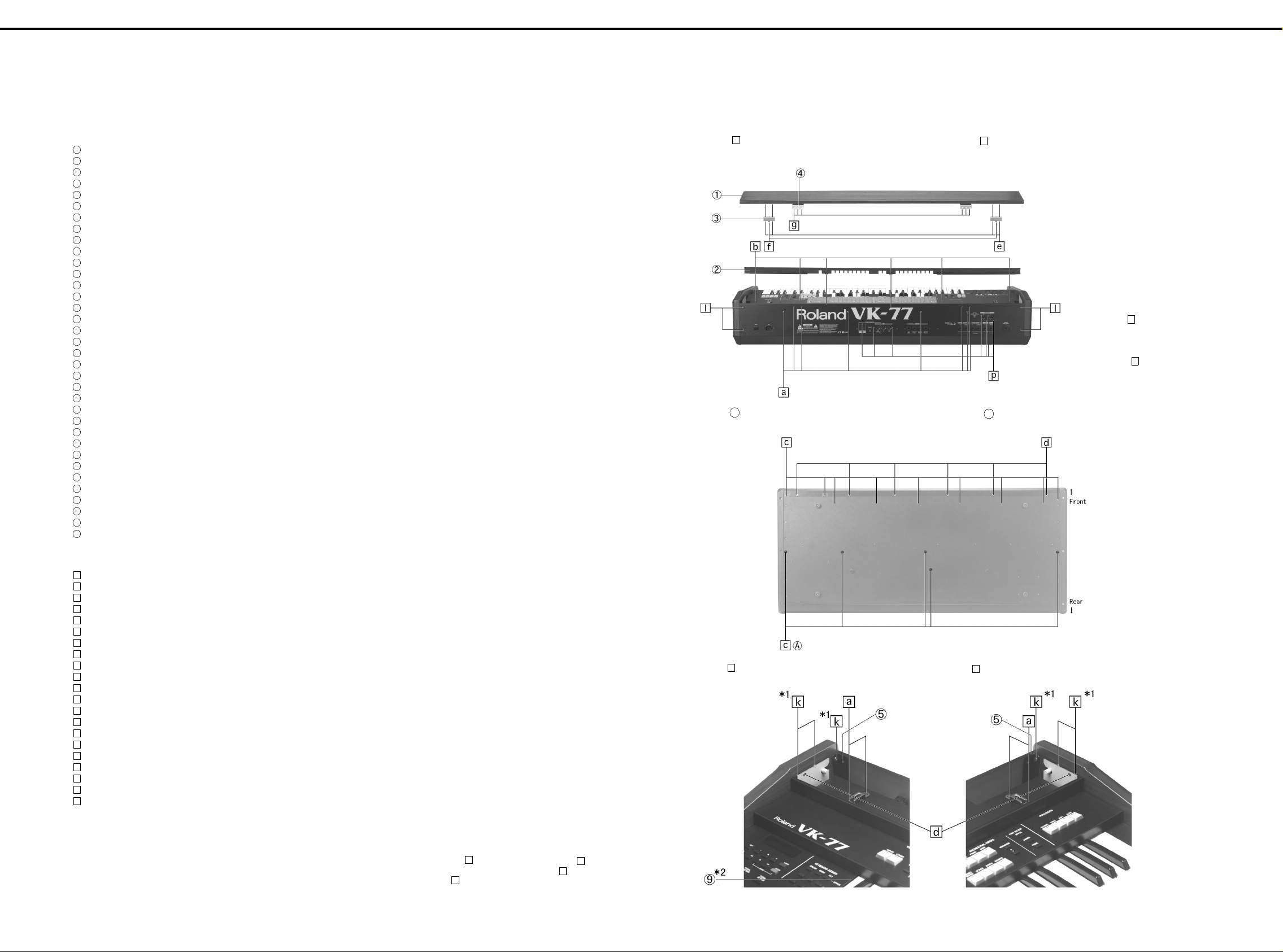
EXPLODED VIEW /分解図
[PART]
NO.PART CODEPART NAME DESCRIPTION
1
71343523 TOP BOARD ASSY CB
2
01676734 ESCUTCHEON H-BAR
3
01676690 SPACER
4
01676767 TOP BOARD HOLDER
5
22125675 ANGLE 212-675
6
22105129 ANGLE 210-129
7
01676901 VR HOLDER
8
01676912 END BLOCK CAP LOWER
9
01676945 END BLOCK CAP UPPER
10
00348345 END BOLCK UR
11
01676789 SIDE HOLDER R
12
01784245 UPPER KEYBOARD ANGLE
13
01123412 STAND D
14
01782490 STAND D
15
01676701 BLIND UPPER
16
71124512 PANEL A BOARD ASSY
17
71124523 PANEL B BOARD ASSY
18
71124534 PANEL C BOARD ASSY
19
71124545 PANEL D BOARD ASSY
2
71230934 REGIST L BOARD ASSY
21
71230945 REGIST R BOARD ASSY
22
00127378 LCD RCM7044U-1A
2
71231034 PS ASSY
24
71231078 INLET BOARD ASSY
26
01450212 POWER TRANSFORMER 01450212 UNIVERSAL
27
71124445 MAIN BOARD ASSY (EXG)
2
71124490 VOLUME BOARD ASSY
2
71124501 PHONES BOARD ASSY
30
71124467 ANALOG BOARD ASSY WITH JACK BOARD
31
71231056 CANNON BOARD ASSY
32
71232267 PEDAL BOARD ASSY
33
71124489 MIDI BOARD ASSY
34
00238290 STAND A
35
71343501 SIDE PNL L ASSY CB
36
71343512 SIDE PNL R ASSY CB
34
33
45
44
/分解図
/分解図/分解図
56
55
67
66
78
77
89
88
910
99
10 11
1010
11 12
1111
12 13
1212
13 14
1313
14 15
1414
15 16
1515
Disassembling
1.
1.1 Remove screws (8 pcs).
1.2 Slide ① toward the keyboard and remove it.
2. Remove screws (5 pcs).
16 17
1616
17 18
1717
A
18 19
1818
a
19 20
1919
20 21
2020
21 22
2121
22 23
2222
23 24
2323
分解手順
分解手順
分解手順分解手順
1
a
のネジ8本を取ります。
1-1.
①を鍵盤側にスライドさせて外します。
1-2.
A
のネジ5本を取ります。
2.
24 25
2424
25 26
2525
*Unless otherwise instructed,
use screw to secure PWB
assemblies to the rear panel.
*
26 27
2626
REAR PANEL
PWB ASSY
無い場合、 で止めます。
27 28
2727
o
に固定する。
は、特に指示が
o
28
2828
MMMM
NNNN
OOOO
PPPP
QQQQ
RRRR
SSSS
TTTT
UUUU
[SCREW]
a
40011123 SCREW M4X8 BINDING B-TIGHT BZC
b
40011067 SCREW M3X8 BINDING TAPTITE B FE ZC
c
40128512 SCREW M4X25 PAN WASHER HEAD TAPTITE B BZC
d
40126267 SCREW M4X16 PAN MACHINE W/SW BZC
e
40010678 SCREW M4X20 TRUSS TAPPING A1 FE BZC
00239367 SHOULDER SCREW 1165
f
g
40012090 SCREW M4X12 TRUSS TAPPING A1 FE ZC
h
40011789 NUT M3 HEX ZC
i
40011056 SCREW M3X6 BINDING TAPTITE B ZC
j
40013067 SCREW M3X8 PAN SEMS FE ZC
k
40010667 SCREW M4X16 TRUSS TAPPING-A FE BZC
l
40013012 SCREW M4X10 PAN SEMS FE BZC
m
40011189 SCREW M3X8 PAN TAPTITE-P FE ZC
n
40011145 SCREW M3X6 FLAT TAPTITE B FE BZC
o
40011501 SCREW M3X8 PAN MACHINE W/SW FE BZC
p
40011312 SCREW M3X8 BINDING TAPTITE P FE BZC
q
40012301 SCREW M4X8 BINDING TAPTITE B FE ZC
r
40126267 SCREW M4X16 PAN MACHINE W/SW BZC
s
40012867 SCREW M3X8 PIN MACHINE W/SW+PW ZC
t
40011101 SCREW M3X8 BINDING TAPTITE B FE BZC
u
40011090 SCREW M3X6 BINDING TAPTITE BZC
*1 Secure (5) with screw (3 pcs
each).
*2 Secure with screw (3 pcs).
3. Remove scr ews (2 pcs).
k
n
*1 ⑤は で各3個止めます。
*2 3本で止めます。
k
n
d
d
のネジ2本を取ります。
3.
4
Page 5
Apr,1999 VK-77
11112
AAAA
BBBB
23
22
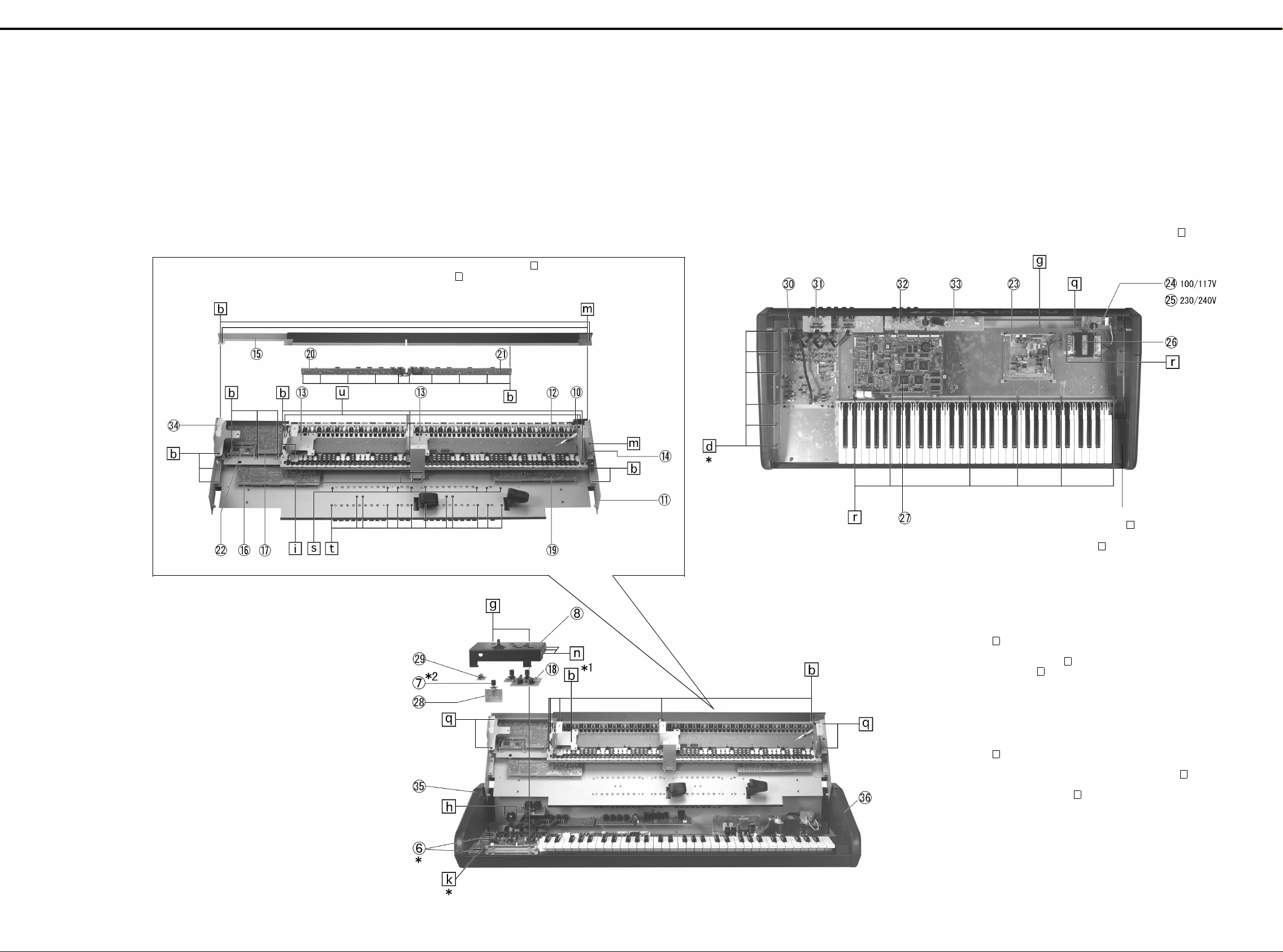
4. Hold and open the upper keyboard and upper panel.
The upper panel, when opened to its full extent, will be retained
at its full open state.
CAUTION: The open top panel easily looses product balance.
CCCC
DDDD
EEEE
FFFF
GGGG
HHHH
34
33
Support the product when working on it.
Take care not to scratch the inside surface of 35 and
36.
45
44
56
55
67
66
78
77
89
88
910
99
上鍵盤と共に上部パネルを持ち上げて開口します。
4.
上部パネルは開けきる事で開口状態を保持します。
注1. 開口状態は製品のバランスが悪くなるので、倒さないよう
に注意して下さい。
注2. 開口時に35、36を傷付けないように注意して下さい。
* Secure with screw (17 pcs).
b
*
17
10 11
1010
11 12
1111
本で止める。
12 13
1212
b
13 14
1313
14 15
1414
15 16
1515
16 17
1616
17 18
1717
18 19
1818
19 20
1919
20 21
2020
21 22
2121
22 23
2222
23 24
2323
Secure rear panel and bottom board with screw (6 pcs).
リアパネルとボトムボードはこのネジ6本で止めています。
24 25
2424
25 26
2525
26 27
2626
27 28
2727
g
28
2828
IIII
JJJJ
KKKK
LLLL
MMMM
NNNN
OOOO
PPPP
QQQQ
RRRR
SSSS
TTTT
* 1 Also secure 01455634.
* 2 Secure with washer and nut supplied with the
potentiometer.
*
1 01455634
*2VR 付属ワッシャとナットで固定します。
共締め
* Same for righthand side.
*右も同様。
Secure end block holder 01676756 to end
block R with screw .
END BLOCK Rに01676756END BLOCK
HOLDER
Notes:
1) Secure 8 PWB holders 00900467 to bottom board with screw
g
(16 pcs).
2) Secure PWB, LCD and bender unit to the bottom board or
panel with screw unless otherwise specified.
Use screw on the main board and analog board (2 pcs
each) where mark "M3 SEMS" is silk-screened.
3) Grounding wires 01890156 between the rear panel and upper
panel and the grounding wire between the rear panel and
analog board, if removed, must be reconnected as they were.
(Terminate one end at the center of the unit and at the mark B
on the analog board.)
注
1. 00900 467 PWB HOL DER 8コはBOTTOM BOARD
g
16
注
2. BOTTOM BOARD及びPANEL
と
BENDER UNIT
MAIN BOARD, ANALO G BO ARD
の表記が有る箇所は で止めます。(各2箇所)
注
3. REAR PANEL
ANALOG BOARD ASSY
(01890156 WIRING GROUND)
に接続して下さい。
本は本体中央、1本は
1
B)と共締めです。
j
本で止めます。
と上部パネル、
がで止まります。
i
は、特に指示が無い場合は、 で止めます。
j
ANALOG BOARD
m
m
に固定する
にシルク印刷で
REAR PANELとPWB
をつないでいるグランド線
を外した際には、必ず元通り
PWB ASSY, LCD
i
のネジ(シルク
にネジ
M3 SEMS
UUUU
* Same for righthand side.
*右も同様。
5
Page 6
Apr,1999VK-77
PARTS LIST /パーツリスト
SAFETY PRECAUTIONS:
The parts marked have
safety-related characteristics.
Use only listed parts oor
replacement.
安全上の注意:
が付いている部品は、安全
上特別な規格でつくられたも
のです。
交換の際は、注意をよく読み、
指定された部品番号以外の部
品は使わないようにして下さ
い。
/パーツリスト
/パーツリスト/パーツリスト
SAFETY PRECAUTIONS:
The parts marked have safety-related characteristics. Use only listed parts oor replacement.
Ex. 10 22575241 Sharp Key C-20/50
Failure to completely fill the above items with correct number and description will result in delayed or
even undelivered replacement.
パーツ発注に関するお願い
パーツ発注に関するお願い
パーツ発注に関するお願いパーツ発注に関するお願い
オーダーシートには、必ず下記の4項目は正確に記入して下さい。(例外は除く)
例
もし記入漏れ、誤記等が有る場合、必要部品が発送出来なかったり、大幅な遅れの原因になります。
ご協力をお願いします。
QTY PART NUMBER DESCRIPTION MODEL NUMBER
15 2247017300 Knob (orange) DAC-15D
必要数
) 10 22575241 Sharp Key C-20/50
15 2247017300 Knob (orange) DAC-15D
パーツナンバー 品 名 使用機種
NOTE: The parts marked # are new. (initial parts)
注意:#が付いた部品は新規部品です。
ANALOG BOARD ASSY → ANB CANNON BOARD ASSY → CB INLET BOARD ASSY → IB
JACK BO ARD ASSY→JB LOWER H-BAR ASSY→LHB MAIN BOARD ASSY→MAB
MIDI BOARD ASSY→MIB PANEL A BOARD ASSY→PAB PANEL B BOARD ASSY→PBB
PANEL C BOARD ASSY→PCB PANEL D BOARD ASSY→PDB PEDAL BOARD ASSY→PEB
PHONES BOARD ASSY→PHB PS BOARD ASSY→PSB REGIST L BOARD ASSY→RLB
REGIST R BOARD ASSY→RRB UPPER H-BAR ASSY→UHB VOLUME BOARD ASSY→VB
CASING/ ケース
00348345 END BOLCK UR
01230678 DISPLAY COVER
# 01676701 BLIND UPPER
# 01676712 BLIND LOWER
# 0 167 6723 REAR P ANEL
# 01676734 ESCUTCHEON H-BAR
# 01676790 END BLOCK R
# 0 167 6867 BENDE R PAN EL
# 01676912 END BLOCK CAP LOWER
# 01676945 END BLOCK CAP UPPER
# 01676934 LCD PANEL
# 01676978 H-BAR PANEL
# 01784212 POWER SWITCH COVER
# 01784245 UPPER KEYBOARD ANGLE
22105129 ANGLE 210-129
22125675 ANGLE 212-675
22135612 F B-ESCT MX1H BLK
# 71233678 BOTOM BOARD ASSY
# 71343501 SIDE PNL L ASSY
# 71343512 SIDE PNL R ASSY
# 7 1343523 TOP BOARD ASSY
CHASSIS/ シャーシ
00238290 STAND A
00900467 PWB HOLDER
01123412 STAND D
01230645 HOLDER H-BAR HOLDER
# 01676745 CENTER HOLDER
# 01676756 END BLOCK HOLDER
# 0 1676767 TOP BOARD HOLDER
# 01676778 SIDE HOLDER L
# 01676789 SIDE HOLDER R
# 01676901 VR HOLDER
# 01676990 H-BAR HOLDER
# 01782490 STAND D
22195973 AMP HOLDER 219-973
22195975 POWER TR HOLDER 219-975
KNOB, BUTTON/ つまみ、
00341134 M R-KNOB LF BLK/BLU
00900145 D S-KEYTOP SD1H BLK
00900167 D S-KEYTOP SD3H BLK
00900189 D S-KEYTOP SX1H BLK
00904245 D S-KEYTOP SX3H BLK
01012978 D S-KEYTOP SX1H MCG
01018690 T S-KEYTOP MD1H MWG
01129767 D S-KEYTOP SX1H DRD
01129778 T S-KEYTOP MD1H DBR
22495277 DS-KEYTOP MD1H BLK 249-277(W/WINDOW)
22495565 RACK POWER BUTTON 249-565 BLACK
SWITCH/ スイッチ
00230489 SSSF12351A SLIDE SWITCH SW1 on MIB
01239645 15RL-120- S 809 -0 0-679 MANUAL PUSH SWITCH SW1 on RLB
01239667 15RL-120- S 809 -0 0-4 90 1 PUSH SWITCH SW2 on RLB
01239678 15RL-120- S 809 -0 0-4 91 2 PUSH SWITCH SW3 on RLB
01239689 15RL-120- S 809 -0 0-4 92 3 PUSH SWITCH SW4 on RLB
01239690 15RL-120- S 809 -0 0-4 93 4 PUSH SWITCH SW5 on RLB
01239701 15RL-120- S 809 -0 0-4 94 5 PUSH SWITCH SW6 on RRB
01239712 15RL-120- S 809 -0 0-4 95 6 PUSH SWITCH SW7 on RRB
01239723 15RL-120- S 809 -0 0-4 96 7 PUSH SWITCH SW8 on RRB
01239734 15RL-120- S 809 -0 0-4 97 8 PUSH SWITCH SW9 on RRB
# 0 167 3767 15RL -1 20- S809-00-974 BANK PUSH SWITCH SW11 on RRB
# 0 167 3778 15RL -1 20- S809-00-975 A/B PUSH SWITCH SW10 on RRB
!
13129160 SDDLB1-B-D-2 TV-5 5A/250V AC PUSH SWITCH
13169727 SKPDAC 250G TACT SWITCH SW1,2 on PAB,SW35~46 on PDB, SW27,29 on PCB
01340290 EVQ11A SWITCH (TACT) SW3,4 on PAB, SW32~34,47,48 on PDB,
ケース
ケースケース
シャーシ
シャーシシャーシ
スイッチ
スイッチスイッチ
つまみ、 ボタン
ボタン
つまみ、つまみ、
ボタンボタン
SW30,31 on PCB, SW5~26,28 on PBB
JACK, SOCKET/ ジャック、ソケット
00340223 YKF51-5031 DIN SOCKET JK18 on MIB
00679767 NC3MAH JACK (CANNON) JK15,17 on CB
!
00789378 NC-173-10(N-L2) 3P AC INLET JK1 on IB
01129145 YKB21-5268(=YKB21-5255) JACK STEREO JK14 on PHB
01230045 ROTARY CABINET JACKS ASSY SUB-MUGNAL SOCKET ASSY AB(CN6)-ROTARY
13429273 YKF51-5046 MIDI CONNECTOR (TRIPRET) JK9 on MIB
13449145 YKB21-5010 JACK JK1,5,7 on JB, JK11~13 on PEB
13449146 YKB21-5012 JACK (W/SW) JK10 on PEB
13449258 HLJ4306-01-3080 6.5MM JACK JK3,6,8 on JB
DISPLAY UNIT/ 表示ユニット
00127378 RCM70 44U-1A LCD
NOTE: Replacement LCD RCM7044U-1A should be made on a unit base.
注意: LCDRCM7044U-1Aの交換は、ユニット単位で行って下さい。補修品は、ユニット単位。
BENDER UNIT/ ベンダーユニット
23275894 PB-A0203 (327-894) BENDER UNIT
NOTE: Replacement PB -A0103 327-894 should be made on a unit base.
注意: PB-A0103327-894 の交換は、ユニット単位で行って下さい。補修品は、ユニット単位。
KEYBOARD ASSY/ 鍵盤完成品
# 71124334 SK-961-D KEYBOARD ASSY
NOTE: See 'KEYBOARD PARTS LIST' for details.
注意: 詳しくは、鍵盤パーツリストを参照してください。
# 71230956 SK-961-F KEYBOARD ASSY
NOTE: See 'KEYBOARD PARTS LIST' for details.
注意: 詳しくは、鍵盤パーツリストを参照してください。
PWB ASSY/ 基板完成品
# 71124489 MIDI BOARD ASSY
NOTE: 'MIDI BOARD ASSY' includes the following parts.
注意: 補修用
# 71124445 MAIN BOARD ASSY
E
# 71124467 ANALOG BOARD ASSY
NOTE: 'ANALOG BOARD ASSY' includes the following parts.
注意: 補修用
# 71124490 VO LUME BOARD ASSY
# 71124501 PHO NES BOARD ASSY
# 71124512 PANEL A BOARD ASSY
# 71124523 PANEL B BOARD ASSY
# 71124534 PANEL C BOARD ASSY
NOTE: 'VK-77 PANEL C BOARD ASSY' includes the following parts.
注意: 補修用
# 71124545 PANEL D BOARD ASSY
# 71231034 PS ASSY
NOTE: 'PS BOARD ASSY' includes the following parts.
注意: 補修用
# 71230934 REGIST L BOARD ASSY
# 71230945 REGIST R BOARD ASSY
# 71231001 LOWER H-BAR ASSY
NOTE: 'LOWER H-BAR ASSY' includes the following parts.
注意: 補修用
# 71231012 UPPER H-BAR ASSY
NOTE: 'VK-77 UPPER H-BAR ASSY' includes the following parts.
注意: 補修用
ジャック、ソケット
ジャック、ソケットジャック、ソケット
表示ユニット
表示ユニット表示ユニット
ベンダーユニット
ベンダーユニットベンダーユニット
鍵盤完成品
鍵盤完成品鍵盤完成品
基板完成品
基板完成品基板完成品
MIDI BOARD ASSY
# 00890390 RIBBON CABLE 10x100-P2.0 MAB(CN10)-MIB(CN8)
ANALOG BOARD ASSY
** ** ** ** JACK BOARD ASSY
01782134 RIBBON CABLE 6x150-P2.0 AB(CN16)-JB(CN17)
01782145 RIBBON CABLE 7x150-P2.0 AB(CN23)-JB(CN25),AB(CN21)-JB(CN22)
PANEL C BOARD ASSY
00789790 RIBBON CABLE 4x500-P2.0 PCB(CN14)-MAB(CN1)
PS BOARD ASSY
01349990 WIRING W4 TB(CN3)-PSB(CN4)
LOWER H-BAR ASSY
01782067 RIBBON CABLE 13x500-P2.0 LHB(CN2)-MAB(CN4)
01230645 H-BAR HOLDER
01676990 H-BAR HOLDER
01673790 H-BAR KNOB IVO/BLK ORCH
32485227 H-BAR KNOB IVO/BLK 4
32485222 H-BAR KNOB IVO/BLK 1
32485229 H-BAR KNOB IVO/BLK 8
32485230 H-BAR KNOB DBR/LCG 16
32485224 H-BAR KNOB BLK/LCG 1.3/5
32485223 H-BAR KNOB BLK/LCG 1.1/3
32485225 H-BAR KNOB IVO/BLK 2
32485226 H-BAR KNOB BLK/LCG 2.2/3
32485228 H-BAR KNOB DBR/LCG 5.1/3
40233012 BINDING TAPTITE P 2.6*8 BZC
40013056 W/SW+SMALL PW M3*6 ZC PAN MA CHINE SCREW
22150513 STANDOFF M3 L12
UPPER H-BAR ASSY
01782056 RIBBON CABLE 14x350-P2.0 UHB(CN1)-MAB(CN3)
01230645 H-BAR HOLDER
01676990 H-BAR HOLDER
32485230 H-BAR KNOB DBR/LCG 16
01673789 H-BAR KNOB DBR/LCG 8
32485225 H-BAR KNOB IVO/BLK 2
32485222 H-BAR KNOB IVO/BLK 1
32485228 H-BAR KNOB DBR/LCG 5.1/3
32485229 H-BAR KNOB IVO/BLK 8
32485226 H-BAR KNOB BLK/LCG 2.2/3
32485223 H-BAR KNOB BLK/LCG 1.1/3
32485224 H-BAR KNOB BLK/LCG 1.3/5
32485227 H-BAR KNOB IVO/BLK 4
40233012 BINDING TAPTITE P 2.6*8 BZC
40013056 W/SW+SMALL PW M3*6 ZC PAN MA CHINE SCREW
22150513 STANDOFF M3 L12
は、下記の部品を含みます。
は、下記の部品を含みます。
は、下記の部品を含みます。
は、下記の部品を含みます。
は、下記の部品を含みます。
は、下記の部品を含みます。
6
Page 7
Apr,1999 VK-77
# 71231056 CANNON BOARD ASSY
# 71231078 INLET BOARD ASSY
NOTE: 'INLET BOARD ASSY' includes the following parts.
注意: 補修用
NOTE: 'INLET BOARD ASSY' does not include the Fuse.
注意: 補修用
# 71232267 PEDAL BOARD ASSY
NOTE: 'PEDAL BOARD ASSY' includes the following parts.
注意: 補修用
IC/ 集積回路
集積回路
集積回路集積回路
00231889 TC74VHC32F-EL IC IC26 on MAB
00232567 PCM69AU-1/T2 IC DAC IC52~54 on MAB
00236845 TC74VHC245F-EL IC (CEM CMOS) IC50 on MAB
00343823 M60205-0601FP IC (GATE ARRAY) IC10 on MAB
00456856 TD62593AP TRANSISTOR ARRAY IC2 on RLB
00780312 TC74W126FU TE12L IC (CMOS) IC67 on MAB
00781689 TC74HC238AP IC (CMOS) IC1 on RLB
00897078 RA01-005 (TC170C200AF-005) IC (CUSTOM) IC35,36,44,45 on MAB
01122412 TC551001CF-70L IC SRAM IC19,20 on MAB
01126612 TC514260DJS-60(YEL) IC (DRAM) IC31,34,40,43 on MAB
01341167 LH28F400SUT-NF60 IC FLASH MEMORY IC18 on MAB
# 01677912 IC MASK ROM UPD23C64000GX-316 IC33,62 on MAB
# 01677923 IC MASK ROM UPD23C64000GX-317 IC42 on MAB
# 01677934 IC MASK ROM UPD23C64000GX-318 IC66 on MAB
# 01677956 IC CPU HD6477034F20 VER1.00 IC17 on MAB
!
# 01679389 REGULATOR AN7820F IC7 on PSB
!
# 01679390 REGULATOR AN7920F IC8 on PSB
15169304H0 HD74LS04P IC(6 INVERTERS) IC15 on MIB
15169550T0 TC74HC138AP IC(CMOS) IC4,6 on PAB
15169556T0 TC74HC574AP IC (C MOS TTL) IC5 on PAB
15189184 NE5532 IC (OP AMP) DIP IC1~5 on AB
15189250 M5218AL IC (OP AMP) IC6,8~14 on AB
!
15199133 AN7815F IC (REGULATOR) IC2 on PSB
!
15199134 AN7915F IC (REGULATOR) IC3 on PSB
!
15199201 STR9005 IC (POWER AMP) IC1 on PSB
15199286 AN78L05M-(E1) IC REGULATOR IC51 on MAB
15199937 M51953BFP IC (RESET IC) IC12 on MAB
15229706S0 PC910 IC PHOTO COUPLER IC16,17 on MIB
15239124 SSC1000 IC IC28 on MAB
15249111 TC7WU04F(TE12L) IC (C MOS) IC48 on MAB
15259702T0 TC74HC02AF(TP2) IC (HS-CMOS) IC37,49 on MAB
15259713T0 TC74HC21AF(TP2) IC (HS-C MOS) IC24 on MAB
15259862T0 TC74HC4050AF(TP2) IC IC16 on MAB
15259863T0 TC74HC4051AF(TP2) IC (C MOS) IC1,2,3,4 on MAB
15259883 TC7S00F(TE85L) IC (C MOS) IC13 on MAB
15259889 TC7S02F(TE85L) IC IC47 on MAB
15289105 UPC4570G2-E2 IC (OP AMP) IC5~9,30,55~58,60 on MAB
15289111 TL062CPS TAP-L IC(OP AMP) IC27 on MAB
01890367 TC74UHC175FT(EL) IC IC70 on MAB
15259885 TC7S32F(TE85L) IC IC71 on MAB
TRANSISTOR/ トランジスター
00785945 RN1224-TPE4 DIGITAL TRANSISTOR Q2~9 on PAB
00898201 RN2421-TE8 5L TRANSISTOR Q5 on MAB
15119141 DTA114ESTP DIGITAL TRANSISTOR Q35 on MIB, Q27,30 on AB, Q37,39,41 on PEB
15119163 RN2227(TPE4) TRANSISTOR
15119615 2SB647C TZ TRANSISTOR Q24,33 on AB
15129151 2SC1815-GR(TPE2) TRANSISTOR Q3 on RLB, Q1,2 on RRB, Q34 on AB, Q13,14,24 on PSB
15129152 2SC2878-A(TPE-2) TRANSISTOR Q1~10,14,16 on JB, Q43,44,46,48 on CB, Q12,17,20,23,
15129164 DTC114ESTP DIGITAL TRANSISTOR Q36,38,40,42 on PEB
15129623 2SD667CTZ TRANSISTOR Q22,29 on AB
!
15129844 2SD-2012-O TRANSISTOR Q23 on PSB
15129845 2SD1763A-D POWER TRANSISTOR Q25,28,31 on AB
15139124 2SK363-GR(TPE-2) FET TRANSISTOR Q10~12,21 on PSB
15319107 2SC4116GR-T E 85 R TRANSIS T OR Q6 on MAB
15329503 DTA124EK T146 DIGITAL TRANSISTOR Q1 on MAB
DIODE/ ダイオード
ダイオード
ダイオードダイオード
00899023 LNJ282RKRXE LED LED89~94 on PAB
01016790 MTZJ T-77 12B ZENER DIODE D99 on PSB
01121323 DA204U T106 ARRAY DIODE DA1,2,7,8,9,12 on MAB
01127489 RB715F T106 SCHOTTKY DIODE DA11 on MAB
01348623 SLR-56VCT32 LED LED87,88 on PAB, LED142~153 on PDB, LED134,
15019444 MTZ T-77 9.1B DIODE (ZENER) D100,101 on PSB
!
15039159T0 S5688G(TPA3) DIODE D2,4,5,105~108,157~160 on PSB
!
15039166 S2VB20-4001L15 DIODE D3 on PSB
!
15039172 S4VB20-4001L15 DIODE D1 on PSB
15039245 SEL6210S LED LED139~141 on PDB, LED131,1 33 on PCB, LE D53~55,
15019126 1SS133 T-77 DIODE D1,2,3,4,5 on RLB, D6,7,8,9,10,11 on RRB,
RESISTOR/ 抵抗
00126112 EXBV8V101JV RESISTOR ARRAY RA1~8,36~39,51~55,65~69,72~76,86~90 on MAB
00346690 RCE9A682JAG7A RESISTOR ARRAY RA31~35 on MAB
01011845 EXBV8V0R000V RESISTOR ARRAY RA114~117 on MAB
01013578 EXBV8V470JV RESISTOR ARRAY RA9~17 on MAB
# 01782567 RF1S L15 0.68 OHM J FUSE RESISTOR R25 on PSB
13749805T0 SR25TRE 222 J CARBON RESISTOR R1 on RLB, R2,3 on RRB
15399301 RPC10T 0R0 J MTL.FILM RESISTOR R221,222 on MAB
15399373 RPC10T 101 J 1/10W MTL.FILM RESISTOR R223~225 on MAB
INLET BOARD ASSY
01788156 WIRING GROUND 100MM
01781967 WIRING W1 AC INLET-IB(CN1)
INLET BOARD ASSY
PEDAL BOARD ASSY
01782123 RIBBON CABLE 8x50-P2.0 MIB(CN32)-PEB(CN31)
トランジスター
トランジスタートランジスター
は、下記の部品を含みます。
は、ヒューズを含みません。
は、下記の部品を含みます。
Q1 on PAB, Q19,20,22 on PDB, Q18 on PCB, Q15~17 on PBB
32 on AB
135 on PCB
109~118,132 on PBB
D95~98 on PAB, D71~76,79~86,154~156 on PDB, D8,
9 on MIB,D61,136~138 on PCB, D40~ 46,58~60,62,
119~130 on PBB,D6,7 on AB, D102~104,161~163 on PSB,
D10~17 on PEB
抵抗
抵抗抵抗
15399686 RPC50T101J 100 1/2W RESISTOR MTL.FILM R197 on MAB
15399965 RCE9A103JAG7A (10KOHM X8) RESISTOR ARRAY RA18~22,29,30,50,57~59,70,71,79~81,91,113,
15409113 EXBV8V103JV RESISTOR ARRAY RA23~25, 27,28,56,60~64,77,18,82~85 on MAB
POTENTIOMETER/ ボリューム
01233178 EVJ 069 F01 B14 12M/M R O T A RY POTENTI O M ETER VR1,2 on PCB
01237101 RS40D113A 4PIN SLIDE VR(POTENTIOMETER) VR1~10 on LHB, VR1~11 on UHB
# 01673756 9M/M ROTARY POT. RK0971520 VR2 on VB
CAPACITOR/ コンデンサー
!
00671834 SME35VB220TP 220UF 35V CHEMICAL CAPCITOR C40,41 on PSB
00907689 GRM40F105Z16PT CERAMIC CAPACITOR C115 on MAB
01238301 ECEA1HKA3R3B CHEMICAL CAPACITOR C28 on PSB
!
01239389 ECQV1H683JL3 POLYEST. CAPACITOR C6,7,12,13,16,17,27,42,43,45,46 on PSB
!
01452189 ECKDBE472ZF CERAMIC CAPACITOR C3,9 on PSB
!
01453278 DE1307E 472M-KH CERAMIC CAPACITOR C1,2 on IB
13519452 DD306-959-F104Z25(100NF/25V Z) CERAMIC CAPACITOR C1 on RLB
!
13639144M0 ECA1CM682 CHEMICAL CAPACITOR C5 on PSB
!
13639195J0 SME35VB 2200 CHEMICAL CAPACITOR C11,15 on PSB
!
13639511M0 CHEMICAL CAPACITOR ECA0JM221B C8 on PSB
13639549M0 ECEA1CK470B CHEMICAL CAPACITOR C2 on RLB, C3 on RRB
!
13639550J0 SME16VB100TP 100UF/16V CAPACITOR(CHEMICAL) C14,18,44,47 on PSB
13639551 ECEA1CU221B 220UF/16V CAPACITOR C29 on PSB
!
13639570J0 SME25VB100 TP CHEMICAL CAPACITOR C14,18,44,47 on PSB
15169210S0 50CV1-T CAPACITOR C93,202 on MAB
INDUCTOR, COIL, FILTER/ インダクター、コイル、フィルター
01455623 N2012Z102T01 INDUCTOR CEA FERRITE BEADS L1 ~33 on MAB
12449268 BL02RN2-R62T2 EMI FILTER L1~3,5,7~12,14,15 on JB, L25~30,57,58 on MIB, L40,
!
12449372 SU10VD-20010 2A/250V LINE-FILTER COIL FL1 on IB
12449438 ESD-R-25DB FERRITE-CORE
CRYSTAL, RESONATOR/ クリスタル、
00894023 MA-406 20000MHZ TE24 CRYSTAL X2 on MAB
00901912 MA-406 24.576MHZ TE24 CRYSTAL X3 on MAB
FUSE, FUSE HOLDER/ ヒューズ、ヒューズホルダー
!
12559441 5X20 SB 2 2A/125V FUSE F2,3 on PSB
!
12559442 5X20 SB 2.5 2.5A/125V FUSE On IB (100/117V)
!
12559443 5X20 SB 3.15 3.15A/125V FUSE F4 on PSB
!
12559550 5X20 S506 1.6A T1.6AL250V FUSE On IB (230/240V)
CONNECTOR/ コネクター
00234489 IL-FPC-22SL-N FFC CONNECTOR CN11 on PAB, CN16 on PDB
01120578 IL-FPC-26SL-N FFC CONNECTOR CN8 on PAB, CN13 on PBB
01127290 IL-FPC-24SL-N FFC CONNECTOR CN10 on PAB
01127401 IL-FPC-24ST-N FFC CONNECTOR CN10 on MAB
01344567 B10B-XH- A CONN EC TO R CN26 on AB, CN5 on PSB
13369503 B7B-PH-K- S JST CONNECTOR CN30 on AB, CN18 on PSB
13369515 B5B-PH-KS JST CONNECTOR CN33 on MIB, CN19 on PSB
13369540 B6B-XH-A CONNECTOR CN7 on MAB, CN6 on PSB
13369563 JST B14B-PH-K-S CONNECTOR CN9 on VB, CN3 on AB
13369565 JST B11B-PH-K-S CONNECTOR CN6 on AB
13369566 JST B6B-PH-K-S(6P) CONNECTOR CN9 on VB, CN1 on AB
13369567 B4B-PH-K-S JST CONNECTOR 4P CN14 on PHB, CN5 on AB
13369582 B13B-PH-K-S CONNECTOR CN22 on MAB, CN11 on VB
13369599 52147-0410(4P) WIRE TRAP CN1 on MAB
13369602 52147-0710(7P) WIRE TRAP CN27 on CB
13369603 52147-08 10( 8P ) CONNECTOR CN32 on MIB
13369605 52147-1010(10P) WIRE TRAP CN11 on MAB
13369678 52147-1310(13P) WIRE TRAP CN4 on MAB
13369679 52147-1410 WIRE TRAP CN3 on MAB
13369928 53253-0610 CONNECTOR CN12 on MAB, CN4 on AB
13369933 53253-11 10 CONNECTOR CN13 on MAB
13369944 53254-0810 CONNECTOR CN4 on RLB, CN6 on RRB
13369945 53254-0910(9P) CONNECTOR CN3 on RLB, CN12 on PAB
13369946 53254-1010 CONNECTOR CN1 on RLB, CN5 on RRB
13369947 53254-11 10 (11 P ) CONNECTO R CN2 on RLB
13369949 53254-1310 CONNECTOR CN9 on PAB, CN15 on PCB
13369981 B5P-VH 7A/250V CONNECTOR CN4 on PSB
01908634 14FE-BT-VK-N CONNECTOR CN8 on MAB
13379152 IL-FPC-16ST-N FFC CONNECTOR CN16,17,19 on MAB
13379153 IL-FPC-18ST-N FFC CONNECTOR CN18 on MAB
13429293 51048-0400(4P) CABLE HOLDER CN14 on PCB
13429295 51048-0600(6P) CABLE HOLDER CN17 on JB, CN16 on AB
13429296 51048-0700(7P) CABLE HOLDER CN22,25 on JB, CN21,23,24 on AB
13429297 51048-0800(8P) CABLE HOLDER CN31 on PEB
13429299 51048-1000(10P) CABLE HOLDER CN8 on MIB
13429317 51048-1300(13P) CABLE HOLDER CN2 on LHB
13429318 51048-1400 14PIN CABLE HOLDER CN1 on UHB
13439335 IL-S-6P-S2T2-EF 6P CONNECTOR CN2 on MAB
WIRING, CABLE/ ワイヤリング、ケーブル
# 00789790 RIBBON CABLE 4x500-P2.0 PCB(CN14)-MAB(CN1)
00890390 RIBBON CABLE 10x100-P2.0 MAB(CN10)-MIB(CN8)
01349990 WIRING W4 TB(CN3)-PSB(C N 4)
# 01780956 16x800-A6.0BBR-P1.25-HBL10 FUJI CARD UPPER KEY,LOWERKEY
# 01780967 18x800-A6.0BBR-P1.25-HBL10 FUJI CARD U PPER KEY-MAB(CN19)
# 01780978 24x350-A6.0BBR-P1.25-HBL10 FUJI CARD(~Serial No. ZM30229) MAB(CN10)-PAB(CN10)
# 01780989 22x800-A6.0BBR-P1.25-HBL10 FUJI CARD PAB(CN11)-PDB(CN16)
# 01780990 26x200-A6.0BBR-P1.25-HBL10 FUJI CARD PAB(CN8)-PBB(CN13)
# 01781001 14x800-A6.0BBR-P1.25-HBL10 FUJI CARD(~Serial No. ZM30229) MAB(CN8)-LCD UNIT
# 01902956 24x350-A6.0BBR-P1.25-HBL10-S-C FUJI CARD(Serial No. ZM30330~) MAB(CN10)-PAB(CN10)
# 01902967 14x800-A6.0BBR-P1.25-HBL10-S-C FUJI CARD(Serial No. ZM30330~) MAB(CN8)-LCD UNIT
# 01781934 6x350-P2.5-XHP-XHP-F WIRING PSB(CN6)-MAB(CN7)
# 01781945 10x750-P2.5-XHP-XHP-F WIRING PSB(CN10)-AB(CN26)
# 0 178 19 67 W1 WIRING AC IN LET -IB (CN1)
# 01781978 5x250-P2.0-PH-PH-F WIRING PSB(CN19)-MIB(CN33)
# 0 178 1989 11x450-P2.0-51065-51065-F W IRIN G MAB(CN13)-RLB(CN2)
# 01781990 9x350-P2.0-51065-51065-F WIRING PAB(CN12)-RLB(CN3)
# 0 178 2023 6x300- P 2.0- P H-P H-F WIRING AB(CN1)-VB(CN9)
ボリューム
ボリュームボリューム
コンデンサー
コンデンサーコンデンサー
インダクター、コイル、フィルター
インダクター、コイル、フィルターインダクター、コイル、フィルター
クリスタル、 発振子
クリスタル、クリスタル、
ヒューズ、ヒューズホルダー
ヒューズ、ヒューズホルダーヒューズ、ヒューズホルダー
コネクター
コネクターコネクター
ワイヤリング、ケーブル
ワイヤリング、ケーブルワイヤリング、ケーブル
発振子
発振子発振子
118~121 on MAB
41 on PHB, L42,43,46,47 on CB, L13,16,17,19,21,23,24,
59 on AB, L33~39 on PEB
7
Page 8
Apr,1999VK-77
<Tools required>
Expression pedal (e.g. EV-5)
Pedal s wit ch (e .g. DP-2)
MIDI cable
Headphones
Oscilloscope
Tester
<Entering the test mode>
While holding down [VIBRATO AND CHORUS, UPPER],
[VIBRATO AND CHORUS, LOWER] and [KEYBOARD
ASSIGN EXT, UPPER], turn on power.
<Tests>
1. Identifying version
2. Memory
3. Battery
4. MIDI circuit
5. Volume controls and pedals
6. Hold pedal
7. Switches and LEDs
8. LCD
9. ROTARY TONE cabinet connectors
10. Sounds
11. Effects
Loading factory settings
<Selecting a test>
Pressing the [>] button proceeds to the next test.
Pressing the [ ] button proceeds to the next step in the
current test sequence.
The desired test can be directly selected by pressing the
following button.
[1]: Version identification
[2]: Memory test
[3]: Battery test
[4]: MIDI circuit test
[5]: Volume control and pedal tests
[6]: Hold pedal test
[7]: Switch and LED tests *
[8]: LCD te st
[Bank]: ROTARY TONE cabinet connector test
[A/B]: Sound check
[Manual]: Effects check
* To manually exit this test and proceed to the next test, press
the [ROTARY SOUND], [BRAKE] and [SLOW/FAST] buttons
simultaneously.
<Exiting the test mode>
Simply turn off power.
<Testing procedure>
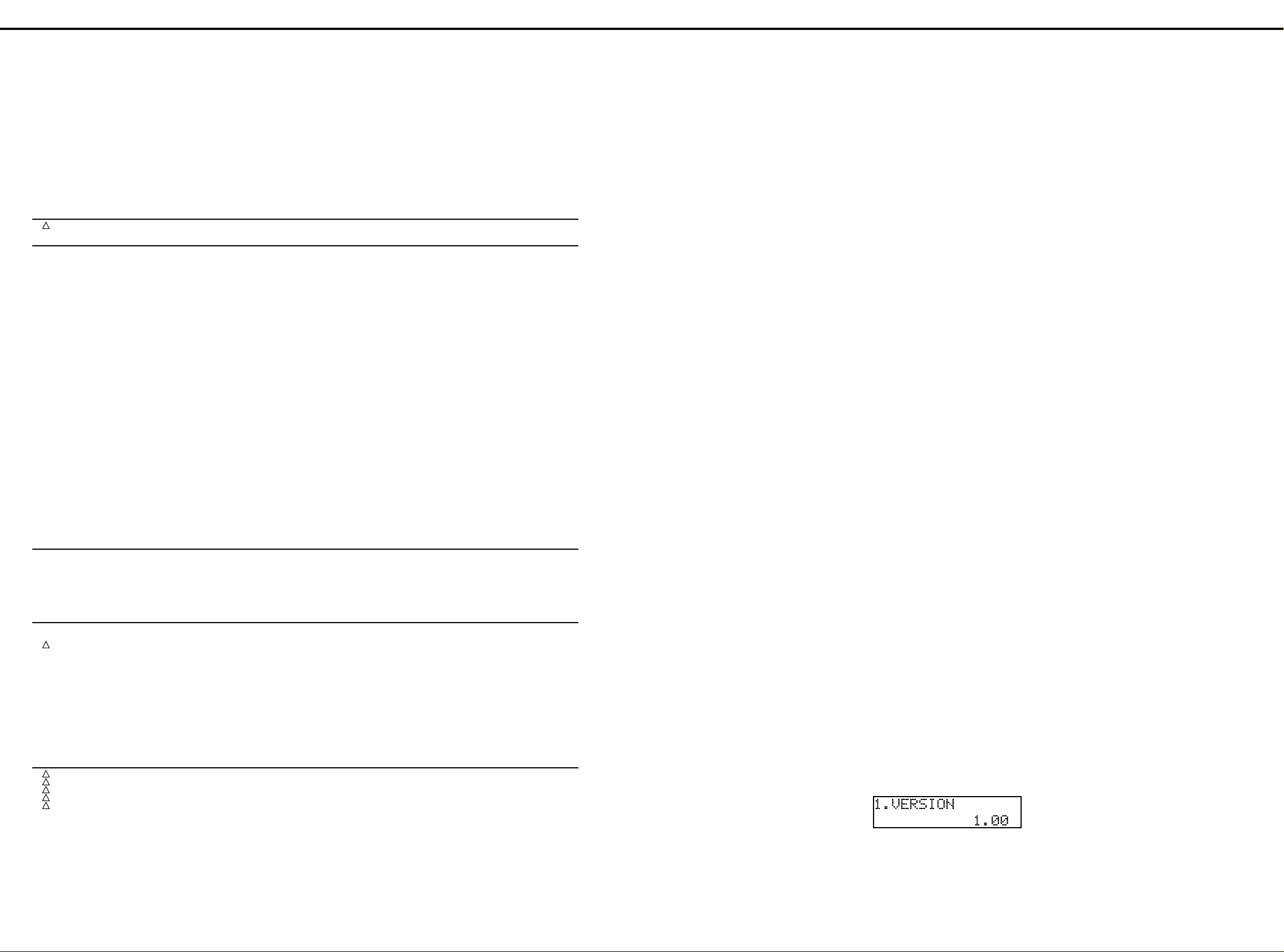
1. Identifying version
The LCD shows the version of the operating program.
<準備するもの>
<準備するもの><準備するもの>
<準備するもの>
エクスプレッションペダル(EV −5 等)
ペダルスイッチ(DP −2 等)
MIDI ケーブル
ヘッドフォン
オシロスコープ
テスター
<テストモードの入り方>
<テストモードの入り方><テストモードの入り方>
<テストモードの入り方>
[
VIBRATO AND CHORUS UPPER] と
[
VIBRATO AND CHORUS LOWER] と
[
KEYBOARD ASSIGN EXT − UPPER] を押し
ながら電源を入れる。
<テスト項目>
<テスト項目><テスト項目>
<テスト項目>
1. バージョン チェック
2. メモリー チェック
3. バッテリー チェック
4. MIDI チェック
5. ボリューム/ペダル チェック
6. ホールドペダル チェック
7. スイッチ/ LED チェック
8. LCD チェック
9. ROTARY TONE CABINET 端子 チェック
10.サウンド チェック
11.エフェクト チェック
○ 工場出荷時データのロード
<テストモードの進め方>
<テストモードの進め方><テストモードの進め方>
<テストモードの進め方>
[>]
ボタンを押すと順番に次のテスト項目に進むことができ
ます。
[▼]
ボタンを押すことで各テスト項目の中の検査を進めてい
きます。
また、下記9のボタンを押すことにより検査したいテスト項目
をダイレクトに選ぶこともできます。
[1]
→ バージョン チェック
[2]
→ メモリー チェック
[3]
→ バッテリー チェック
[4]
→ MIDI チェック
[5]
→ ボリューム・ペダル チェック
[6]
→ ホールドペダル チェック
※[7
]
→ スイッチ・LED チェック
[8]
→ LCD コントラスト チェック
[
Bank
]
→ ROTARY TONE
CABINET 端子チェック
[
A/B
]
→ サウンド チェック
[
Manual
]
→ エフェクト チェック
※ スイッチ・LED チェックから強制的に抜ける場合には
[
ROTARY SOUND] と [BRAKE] と [SLOW /
FAST]を同時に押してください。次のテスト項目に進む
ことができます。
<テストモードの抜け方>
<テストモードの抜け方><テストモードの抜け方>
<テストモードの抜け方>
テストモードを中断するには電源を切ってください。
<テスト項目詳細>
<テスト項目詳細><テスト項目詳細>
<テスト項目詳細>
1. バージョン チェック
LCD に バージョンが表示されます。
# 01782034 7x800-P2.0-PH-PH-F WIRING PSB(CN18)-AB(CN30)
# 01782045 6x350-P2.0-51065-51065-F WIRING MAB(CN12)-AB(CN4)
# 01782056 14x350-P2.0 RIBBON CABLE UHB(CN1)-MAB(CN3)
# 01782067 13x500-P2.0 RIBBON CABLE LHB(CN2)-MAB(CN4)
# 01782078 13x450-P2.0-PH-PH-F WIRING MAB(CN22)-VB(CN11)
# 01782089 14x300-P2.0-PH-PH-F WIRING AB(CN3)-VB(CN10)
# 01782090 4x250-P2.0-PH-PH-F WIRING AB(CN5)-PHB(CN14)
# 01782112 13x500-P2.0-51065-51065-F WIRING PAB(CN9)-PCB(CN15)
# 01782123 8x50-P2.0 RIBBON CABLE MIB(CN32)-PEB(CN31)
# 01782134 6x150-P2.0 RIBBON CABLE AB(CN16)-JB(CN17)
# 01782145 7x150-P2.0 RIBBON CABLE AB(CN23)-JB(CN25),AB(CN21)-JB(CN22)
01788156 GROUND 100MM WIRING
# 01890156 GROUND WIRING
# 01891845 8x90-P2.0-51065-51065-F WIRING RLB(CN4)-RRB(CN6)
# 01891856 10x90-P2.0-51065-51065-F WIRING RLB(CN1)-RRB(CN5)
# 01677845 16x550-A6.0BBR-P1.25H10 FUJI CARD MAB(CN18)-LOWER KEYBOARD
# 01782012 10x100-P2.0-51065-51065-F WIRING RLB(CN1)-RRB(CN5)
# 01782001 8x100-P2.0-5165-51065F WIRING RLB(CN4)-RRB(CN6)
TRANSFORMER/ トランス
!
01450212 01450212 UNIVERSAL POWER TRANSFORMER POWER TRANSFORMER
SCREWS/ ねじ類
00239367 1165 SHOULDER SCREW
22150513 M3 L12 STAND OFF
# 22150523 BOSS NUT M3/M4 L8
22150756 JACK NUT 2 JACK NUT 2
40010667 TAPPING-A FE BZC SCREW M4x16 TRUSS
40010678 TRUSS TAPPING A1 FE BZC SCREW M4x20
40011056 BINDING B-TIGHT ZC SCREW 3x6
40011067 BINDING FE ZC SCREW M3x8 B-TIGHT
40011101 TAPTITE-B FE BZC SCREW M3x8 BIND
40011123 BINDING B-TIGHT BZC SCREW 4x8
40011145 B-TITE FE BZC SCREW M3x6 FLAT
40011189 TAPTITE-P FE ZC SCREW M3x8 PAN
40011201 FE BZC SCREW M3x8 PAN P-TITE
40011212 PAN P-TITE BZC SCREW 3x16
40011312 BINDING P-TITE FE BZC SCREW M3x8
40011356 M4X8 S-TIGHT FE BZC SCREW(W/INTERNAL TOOTH WASHER)
40011501 SEMS. PAN HEAD FE BZC SCREW M3x8
40011789 HEX ZC NUT M3
40012089 TRUSS TAP PI NG A1 ZC SCREW 4x10
40012090 TRUSS HEAD TAPPING A1 FE ZC SCREW M4x12
40012301 TAPTITE-B FE ZC SCREW M4x8 BIND
40012345 BINDING B- TI GHT BZC SCREW M4x10
40012478 BINDING HEAD P-TIGHT FE ZC SCREW 4x8MM
40012501 BINDING TAPTITE P FEBC SCREW 4*12MM
40012889 DOUBLE SEMS FE ZC SCREW M3x12 PAN
40012901 SEMS FE ZC SCREW M3x20 PAN
40012956 M3X8 PAN SEMS FE BZC SCREW
40013012 M4X10 PAN SEMS FE BZC SCREW
40013056 W/SW+SMALL PW M3X6 ZC SCREW (PAN MACHINE)
40013067 M3X8 PAN SEMS FE ZC SCREW
40126267 W/SW M4*16 BZC PAN MACHINE SCREW
40128067 M4X18X1.6 FECM WASHER M4x18x1.6
40128512 B-TIGHT WH FE BZC W=11 SCREW (4x25x20MM)
40233012 2.6X8MM BINDING TAPTITE FEBZC SCREW
40012867 PIN MACHINE W/SW+PW ZC SCREW M3x8
40011090 BINDING TAPTITE BZC SCREW M3x6
PACKING/ 梱包材
# 0 167 6612 PAD UP PER L
# 0 167 6623 PAD UP PER R
# 01676634 PAD CARTON LOWER
# 01676645 PAD CARTON CENTER
# 01676656 PACKING CASE
# 0 178 2501 PAD LOWE R
22675517 PACKING SHEET
MISCELLANEOUS/ その他
00900534 BRACKET
# 01235934 DUST COVER A
!
# 01673823 LITHIUM BATTERY CR2450
# 01673834 BATRY HOLDER HL50-A FOR CR2450 BT1 on MAB
# 01676690 SPACER
# 01676890 DUST COVER BND
# 01677123 HEATSINK
# 01788978 CUSHION CRO-NEL 45*250
12189823 FUSE HOLDER CNT47-0003A FH1,2 on IB,FH3~8 on PSB
22675509 TF RUBBER TF-FR-SGP 40x25x0.3
40013812 CAUTION SEAL IEC(100V/117 ONLY)
40014201 FUSE SEAL UL2.5A/125V
40016523 INSULOKTIE T18R << ORDERING PER 1000 PCS >>
40017089 CAUTION SEAL CSA COVER
40017367 COATING CLIP CS-6
40124690 CAUTION SEAL FUSE
ACCESSORIES (Standard)/ 標準付属品
!
00894367 AC CORD SET 100V
!
00894378 AC CORD SET 120V
!
00894389 AC CORD SET 230V
!
00907001 AC CORD SET 230VE
!
23495124 CORD SET SC-405-J01 (240VA)
# 71124278 OWNER'S MANUAL JAPANESE
# 71233823 OWNER'S MANUAL ENGLISH
40232345
ねじ類
ねじ類ねじ類
梱包材
梱包材梱包材
保証書
トランス
トランストランス
その他
その他その他
標準付属品
標準付属品標準付属品
(JAPAN ONLY)
MAB(CN17)-LOWER KEYBOARD
TEST MODE /テストモード
/テストモード
/テストモード/テストモード
○
▼
8
Page 9
Apr,1999 VK-77
When all MIDI tests are OK, remove the MIDI cable and
the program proceeds to the next test.
各 MIDI IN 端子が 「OK」を表示し、MIDI
ケーブルが抜かれると自動的に次のテスト項目に進み
ます。
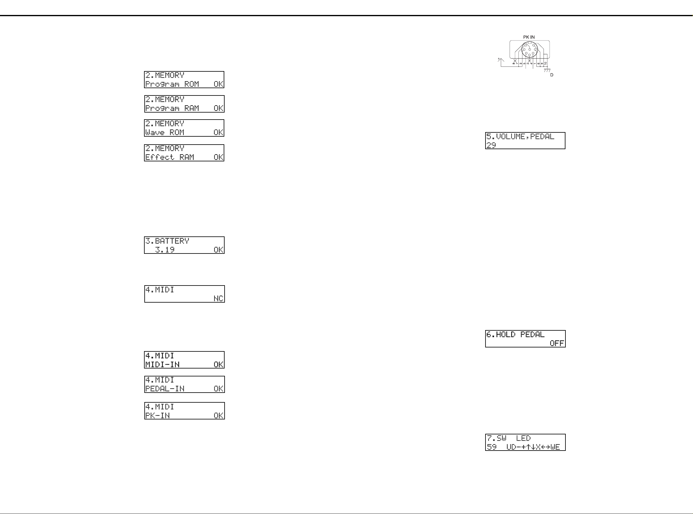
5. Volume control and pedal tests
The LCD displays the number of controls.
5. ボリューム/ペダル チェック
操作子の総数が LCD に表示されます。
Controls: 29
H-BAR (21), REVERB, OVERDRIVE, BENDER,
MODULATION, AFTER TOUCH, EXPRESSION PEDAL,
CONTROL PEDAL 1, CONTROL PEDAL 2
When a control is operated across its full travel range, the
LCD shows the name of the control and current setting.
The setting can also be checked by listening to the output
sound.
When the minimum and maximum settings of the control
are detected, the LCD decreases the count next to the
[VOLUM, PEAL] by one.
* Activating two or more controls at the same time does not
decrease the count on the LCD.
When checking the EXPRESSION PEDAL, CONTROL
PEDAL 1 and CONTROL PEDAL 2, use EV-5 or
equivalent pedal.
When the 29th control has been tested, the program goes
to the next test.
操作子は、
H − BAR (21本)、REVERB、OVER
DRIVE、BENDER、MODULATION、
AFTER TOUCH、EXPRESSION
PEDAL、CONTROL PEDAL 1、
CONTROL PEDAL 2の合計29点です。
操作子を動作させると操作子名とその値を LCD に
表示します。
値の変化は音程の変化でも確認できます。
Min、Max を検知すると操作子数がカウントダウ
ンされます。
※ 同時に複数の操作子が選択された場合はカウントダウンさ
れません。
EXPRESSION PEDAL、CONTROL
PEDAL 1、CONTROL PEDAL 2 の
チェックは EV −5 等のエクスプレッションペダル
を使用してください。
すべての操作子が操作されると自動的に次の項目に進
みます。
6. Hold pedal test
The LCD displays:
6. ホールドペダル チェック
下記のようにディスプレイには表示されます。
Connect a pedal switch (e.g. DP-2) to HOLD PEDAL
socket. Depress the pedal to ON and the LCD displays
"ON".
The program goes to the next test.
HOLD PEDAL 端子に DP −2 等のペダルス
イッチを接続し、ペダルを ON させると、「ON」を
表示して次のテスト項目へ進みます。
7. Switch and LED test
All LEDs except for registrations 1-8 light.
The LCD displays the total number of switches and LEDs.
7. スイッチ/ LED チェック
LED が全点灯します。
※ レジストレーション [1] 〜 [8] は点灯しません。
スイッチ/ LED の総数を LCD に表示します。
Press a switch and the corresponding note will be
generated. The LCD will decrease the number, being
displayed to the right of "SW LED", by one.
スイッチを押すと音が鳴り、スイッチ/ LED の総数
をカウントダウンをします。
2. Memory test
The test program starts the memory test, and upon
completion of successful test goes to the next test.
3. Battery test
When the battery is at a voltage in the range of 2.7 to 3.8
V, the test program displays "OK" and goes to the next
test. Otherwise, it displays "NG" and aborts the test
sequence.
Tu rn off power, remove the cause (e.g. replace the
battery).
Turn on power, enter the test mode again and repeat the
test 3.
2. メモリー チェック
この項目に入ると自動的にチェックを開始します。
すべてが OK ならば自動的に次のテスト項目に進み
ます。
3.バッテリー チェック
バッテリーの電圧が規定の範囲なら「OK」を表示し
て自動的に次の項目に進みます。
「NG」の場合、バッテリー NG を表示して止まりま
す。
※ バッテリー電圧が
い状態も同様)の時にNGとなります。
2.7V
以下、
以上(バッテリーが無
3.8V
4. MIDI test
The LCD displays:
Hook the MIDI OUT socket up to MIDI IN socket through
the MIDI cable.
The LCD will display "OK" (see Fig. 4-9). Repeat the test
by connecting the MIDI cable to [PEDAL-IN] and [PK-IN].
Connect the MIDI OUT to the following MIDI IN socket.
* Verify that approx. 10 V is applied to the pin 7 of PK IN
terminal.
4. MIDI チェック
下図のようにディスプレイには表示されます。
MIDI OUT 端子と MIDI IN 各端子を
MIDI ケーブルでループさせます。
MIDI ケーブルを接続している時、LCDに
「OK」を表示します。
MIDI OUT 端子と MIDI IN 端子接続時
※PK IN 端子の7番ピンの電圧が約10Vあることを確認
してください。
9
Page 10
Apr,1999VK-77
* The rotary speaker effect of the organ voice will not be
applied to the audio signal that is output from the ROTARY
TONE CABINET connector.
1) The VK-77 judges that it is being connected to a rotary
speaker when approx. DC 24 V is on pin 11 of the
rotary connector.
The LCD will display:
※ オルガン・ボイスの回転スピーカー効果は、
ROTARY
TONE CABINET
端子から出力される音声信号にはかかり
ません。
(1)VK −77 はロータリースピーカーの接続をロータ
リーコネクタの11ピンに与えられる電圧によって
検出します。
ディスプレイには下図のように表示されます。
Apply approx. DC 24 V to the pin 11.
The LCD will read:
ロータリースピーカー端子の11ピンに
DC 24 V(24 V 以下でも可)を加えると、表
示が下図のように変わります。
Verify that sound is output to pins 1, 2, 3 and 10 of
the rotary speaker connector.
MASTER VOLUME:MAX
No.1 sine wave 140mVp-p
No.2 sine wave 140mVp-p
(the same as No. 1 wave)
No.3 saw-tooth wave 70Vp-p
No.10 pulse wave 50mVp-p
Press the [ ] button and the program goes to the
next test.
この時、ロータリースピーカー端子の1、2、3、
10ピンから音が出ている事をオシロスコープで確
認して下さい。
MASTER VOLUME:MAX
No.1
サイン波 約
140mVp-p
No.2
サイン波 約
140mVp-p
(
No.1
を繋いでいるだけなので同じです。)
No.3
のこぎり波 約
70mVp-p
No.10
パルス波 約
50mVp-p
[▼]
ボタンを押して次の項目に進みます。
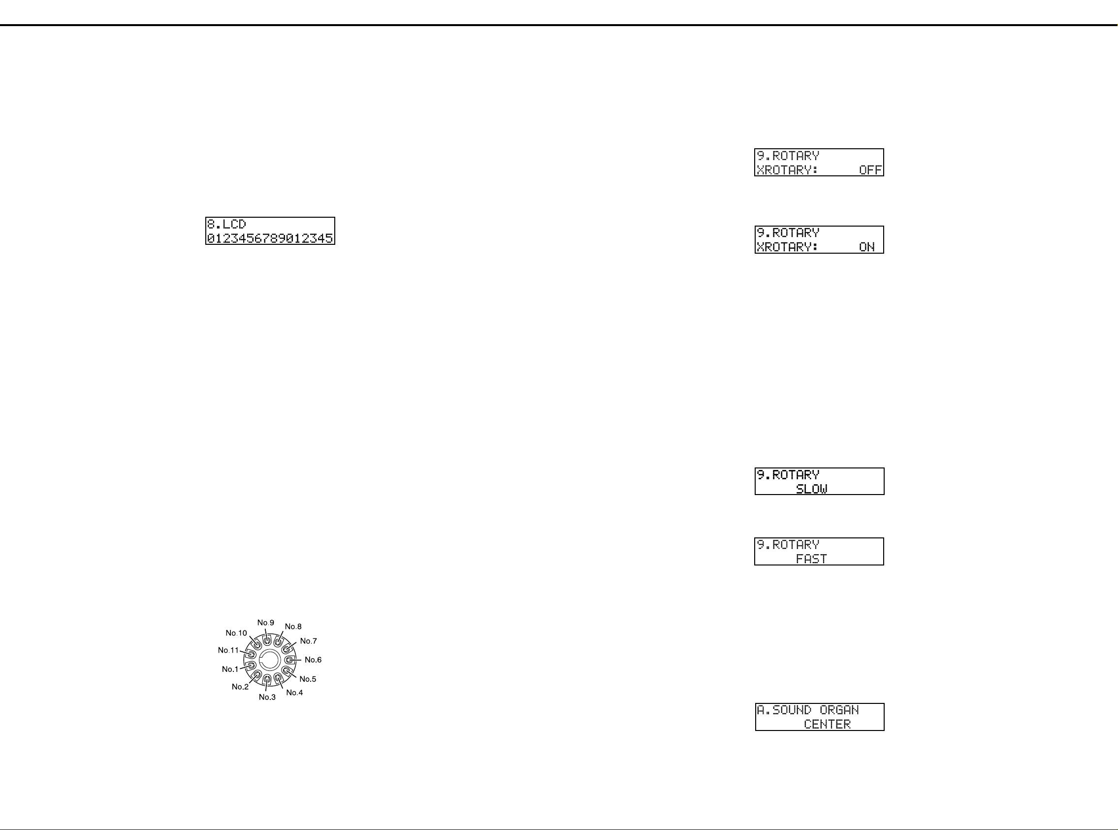
2) Check SLOW/FAST control signal.
The LCD reads SLOW and F AST alternatively as shown
below.
Check the voltage on the pins 7 and 8 of the rotary
speaker connector.
(2)SLOW/ FAST の制御信号の確認をします。
ディスプレイには下図のように SLOW、FAST
が自動的に繰り返し表示されます。
それぞれの状態の時に、ロータリースピーカー端子
の7ピンおよび8ピンが、下記の状態であることを
確認してください。
↑
↓
Upon successful completion of the test, press the [>]
button to proceed to the next test.
上記3項目のテストが終了したら、[>] ボタンを押
して次のテスト項目へ進んでください。
10. S ound test
This test requires the oscilloscope and headphones.
Insert the plug from the headphones into the [PHONES]
socket.
1) Verify sine waves from the headphones.
10.サウンド チェック
ラインアウトを確認します。
オシロスコープとヘッドフォンを準備してください。
ヘッドフォンを PHONES ジャックに接続してく
ださい。
(1)左右から正弦波が鳴ります。
* A keytop having a window turns off its LED when pressed.
* Activating two or more switches simultaneously does not
decrease SW LED counts on the LCD.
After testing all the switches and LEDs, the program goes
to the next test.
* To proceed to the next test before completing the test 7,
press the [ROTARY SOUND], [BRAKE] and [SLOW/FAST]
simultaneously.
8: LCD test
The LCD displays:
Press the [ ] button and the LCD turns on all dots.
Turn [OVERDRIVE] knob from MIN to MAX and verify
changes in contrast.
Press the [ ] button and the LCD turns off all dots.
Press the [>] button and the program goes to the next test.
9. ROTARY TONE cabinet connector test
Perform this test when necessary to check rotar y speaker.
▼
▼
※ 窓ありキートップの場合、スイッチを押すと LED が消灯
します。
※ 同時に複数のスイッチを操作した場合、カウントダウンさ
れません。
すべてのスイッチ/ LED のチェックが済むと、自
動的に次のテスト項目へ進みます。
※ スイッチ・LED チェックから強制的に抜ける場合には
ROTARY SOUND] と [BRAKE] と [SLOW /
[
FAST]を同時に押してください。次のテスト項目に進む
ことができます。
8. LCD チェック
LCD に下図のように表示されます。
ボタンを押すと、ドットが全点灯します。もう一
[▼]
度 [▼] ボタンを押すと、ドットが全消灯します。
LCD コントラストは [OVER DRIVE] ノブで
変化します。
LCD の表示状態を確認後、[>] ボタンを押して次
のテスト項目に進みます。
9. ロータリー端子 チェック
ロータリースピーカーに関連する機能のテストを行う
必要がある場合は、以下のことを検査してください。
* Connecting a speaker which does not meet the following
specifi-cations may cause malfunctions.
The pinout for the ROTARY TONE CABINET connector is
as follows:
No. 1 ORGAN (ROTARY)
No. 2 ORGAN (STATIONARY)
No. 3 ORCHESTRAL L
No. 4 GND
No. 5 GND
No. 6 POWER ON/OFF CONTROL
No. 7 FAST CONTROL
No. 8 SLOW CONTROL
No. 9 NC
No. 10 ORCHESTRAL R
No. 11 +24 V IN
Pin Nos. 1 and 2 are the output of the organ voice.
Pin Nos. 3 and 10 are the output of the orchestral voice .
Pin Nos. 6, 7, and 8 are the open collector output, and are
at a nominal voltage of 5ñ30 V DC, and nominal loaded
current of 50 mA maximum.
Pin no. 11 detects the connection. If the nominal input
voltage is outside the acceptable range (18ñ30 V DC), the
connection will not operate correctly.
※ 以下の規格を満たしていないスピーカーを接続すると、故
障の原因となります。
ROTARY TONE CABINET
になっています。
No.1 ORGAN(ROTARY)
No.2 ORGAN(STATIONARY)
No.3 ORCHESTRAL L
No.4 GND
No.5 GND
No.6 POWER ON/OFF CONTROL
No.7 FAST CONTROL
No.8 SLOW CONTROL
No.9 NC
No.10 ORCHESTRAL R
No.11 +24V IN
No.1とNo.2
No.3とNo.10
す。
No.6、No.7、No.8
で、定格電圧
です。
No.11
力電圧(
ません。
のピンはオルガン・ボイスの出力です。
のピンはオーケストラ・ボイスの出力で
DC5〜30V
のピンでは接続の検出を行っています。定格入
DC18〜30V
端子の各ピンは以下のよう
のピンはオープン・コレクタ出力
、定格負荷電流最大
)範囲外の場合は正しく動作し
50mA
▼
The volume of the external speaker can be adjusted by
the MASTER VOLUME knob.
[FAST/SLOW] will switch the rotational speed of the
connected rotary speaker.
[BRAKE] will temporarily stop the rotation of the
connected speaker. To resume rotation, press [BRAKE]
again, or press [FAST/SLOW].
10
スピーカーの音量は
節します。
[
FAST/SLOW
度を切り換えます。
[
BRAKE
にストップさせることができます。再び回転をス
タートさせるには、もう一度[
[
FAST/SLOW
]は接続した回転スピーカーの回転速
]は、接続したスピーカーの回転を一時的
]を押してください。
MASTER VOLUME
BRAKE
つまみで調
]を押すか、
Page 11
Apr,1999 VK-77
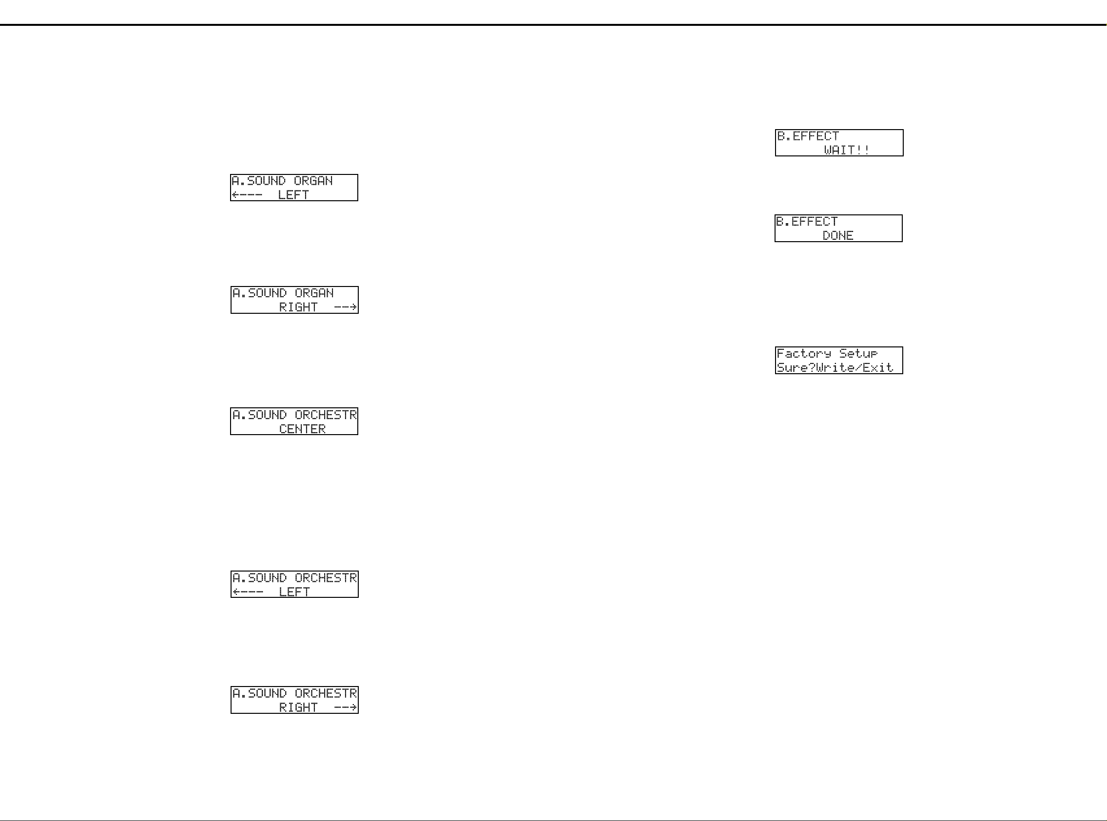
11. Effects test
Connect the headphones to the [PHONES] socket.
The LCD displays:
11.エフェクト チェック
エフェクトサウンドのチェックを行います。
PHONES ジャックにヘッドフォンを接続してくだ
さい。
ディスプレイには下図のように表示されます。
After approx. 4 second of muting, sine wave will be heard.
Check for unusal sounds or noises for approx. 4 seconds
until the LCD displays:
約4秒間の無音状態の後、正弦波が聞こえます。
正弦波が鳴り始めてから約4秒後、ディスプレイは下
図のように変わります。
Press the [>] button to proceed to the next test.
この表示が現れるまで、ヘッドフォンから異音が聞こえ
ないかをチェックしてください。
[>]
ボタンを押して次のテスト項目へ進んでください。
Loading factory settings (initialization)
The LCD displays:
○ 工場出荷時データのロード(イニシャライズ)
ディスプレイには下図のような確認画面になります。
○
Press the [WRITE] button and the factory setting data will
be loaded.
Pressing the [EXIT] button aborts the test.
Exiting the test mode.
Turn off power.
[
WRITE] ボタンを押すと工場出荷時のデータが
ロードされます。
[
EXIT] ボタンを押せば中止できます。
これですべてのテスト項目終了です。
VK −77の電源をオフしてテストモードを終了しま
す。
♦
CAUTION!
Be sure to read the following precautions before starting the
upgrading.
1) Strictly follow the version updating procedure described
below and never turn off power until all steps are
completed.
Otherwise, the VK-77 will not start again.
2) User data may be erased as the result of updating.
Save the user data.
♦
Preparation
1) A program of latest version is availab le from the Roland
service center in a form of 3.5" disk (17048945 VK-77
Ver.up).
2) The program is in SMF format. A compatible sequencer is
required (SB-55).
3) File names
_0000000.mid
_0000001.mid
_0000002.mid
:
:
_0000017.mid
◆警告!!
◆警告!!◆警告!!
◆警告!!
作業前に必ずお読みください
(1) バージョンアップの手順を間違えたり、途中で電源を
切ったりすると VK −77が起動しなくなる場合が
あります。
必ず後述の手順に従い、作業中は絶対に電源を切らな
いようお願いいたします。
(2) バージョンアップ作業によってユーザーデータエリア
が消去される場合があります。
作業前に必ずユーザーデータのバックアップを行って
ください。
◆お読みください
◆お読みください◆お読みください
◆お読みください
(1) バージョンアップデータは3.5インチフロッピー
ディスクからなります。(
17048945
VK −77
Ver.up DISK)最新バージョンをサービスセ
ンターから取り寄せてください。
(2) プログラムデータはSMF 形式となっていますので、
これを演奏できるシーケンサ(SB−55)を用意し
てください。
(3) ファイル名は以下のとおりです。
_0000000.mid
_0000001.mid
_0000002.mid
:
:
_0000017.mid
Observe the outputs to MIX OUT and ORGAN OUTUT
(FIXED) on the scope.
(Connect one channel input probe to the tip of the plug,
the other probe to the ring and GND to the sleeve).
Verify that these waveforms are opposite in phase.
Press the [ ] button.
2) Verify the sawthooth wave sound from the left headphone.
Press the [ ] button.
3) Verify the square wave sound from the right headphone.
Press the [ ] button.
▼
▼
▼
ヘッドフォンで左右から音が出ていることを確認し
てください。
また、オシロスコープを用いて、MIX OUT
PUT と ORGAN OUTPUT(FIXED)
の 両ch の TIP と RING の波形がそれぞれ
反転していることを確認してください。
※ SLEEVE が グランドです。
を押して次の項目に移ります。
[▼]
(2)左から鋸波の音が鳴ります。
ヘッドフォンで左から音が出ていることを確認して
ください。
を押して次の項目に移ります
[▼]
(3)右から矩形波の音が鳴ります。
ヘッドフォンで右から音が出ていることを確認して
ください。
を押して次の項目に移ります
[▼]
4) Verify the sine wave sound from the headphones.
Observe the outputs to ORCHESTRAL OUTPUT
(FIXED) on the scope.
(Connect one channel input probe to the tip of the plug,
the other probe to the ring and GND to the sleeve).
Verify that these waveforms are opposite in phase.
Press the [ ] button.
5) Verify the sawthooth wave sound from the left
headphone.
Press the [ ] button.
6) Verify the square wave sound from the right headphone.
Press the [>] button to proceed to the next test.
▼
▼
(4)左右から正弦波が鳴ります。
ヘッドフォンで左右から音が出ていることを確認し
てください。
また、オシロスコープを用いて、
ORCHESTRAL OUTPUT(FIXED)
の TIP と RING の波形がそれぞれ反転してい
ることを確認してください。
※ SLEEVE が グランドです。
を押して次の項目に移ります
[▼]
(5)左から鋸波が鳴ります。
ヘッドフォンで左から音が出ていることを確認して
ください。
を押して次の項目に移ります。
[▼]
(6)右から矩形波の音が鳴ります。
ヘッドフォンで右から音が出ていることを確認して
ください。
ボタンを押して次のテスト項目へ進んでくださ
[>]
い。
UPGRADING THE VERSION /バージョンアップの方法
/バージョンアップの方法
/バージョンアップの方法/バージョンアップの方法
11
Page 12
•
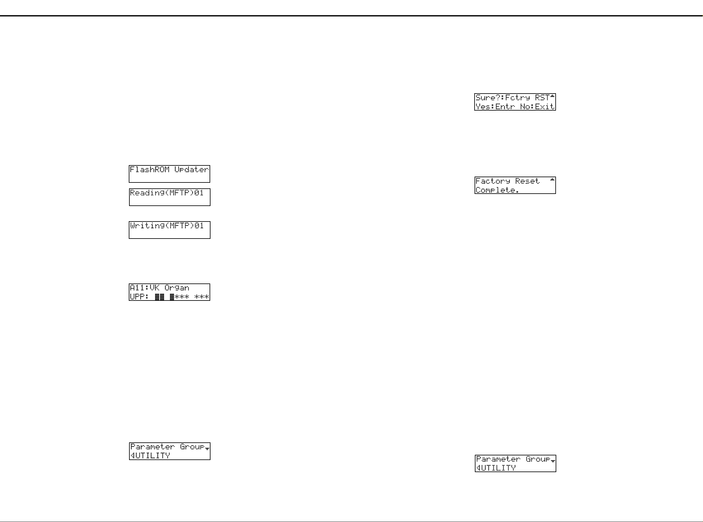
3. Press the [ENTER] or [ ] button.
4. Press the [ ] and [ ] buttons. The LCD will display
"Factory Reset".
5. Press the [WRITE] button. The LCD will show:
3. [ENTER] または [▼] を押します。
4. [ ▲] [▼] を押して Factory Reset
(ファクトリー・リセット)をディスプレイに表示さ
せます。
5. [WRITE] を押します。
ディスプレイがファクトリー・リセット実行の確認の
表示になります。
* To abort the procedure and exit the edit mode, press the
[EXIT] button twice or press the [EDIT] button, skipping the
step 6 below.
6. To recover the factory settings, press the [ENTER] button.
7. The LCD will show:
※ ファクトリー・リセットを中止したいときは、6.の操作
をおこなわずに [EXIT] を2回、または [EDIT] を押
し、エディット・モードを終了してください。
6. ファクトリー・リセットを実行する場合は
[
ENTER] を押します。
7. ディスプレイは以下の表示になり、ファクトリー・リ
セットが実行されます。
Now, factory settings have been loaded.
8. Press the [EXIT] button twice or press the [EDIT].
The [EDIT] indicator will be turned off and the program
will exit the edit mode.
* Alternative method
The VK-77 will also load the factory settings when it is turned
on in the following way:
While holding the buttons [VIBRATO AND CHORUS
TYPE V], [VIBRATO AND CHORUS TYPE C] and
[KEYBOARD ASSIGN EXT-UPPER], turn on power.
8. [EXIT] を2回、または [EDIT] を押します。
[
EDIT] のインジケータが消灯(オフ)になり、
ディット・モードが終了します。
※ ファクトリーリセットは、電源投入時に以下のボタンを押
すことでも実行できます。
バージョンアップを行った後等に行ってください。
[VIBRATO AND CHORUS TYPE V]
と
[VIBRATO AND CHORUS TYPE C]
と
[KEYBOARD ASSIGN EXT-UPPER]
を押しながら電源を
入れる。
•
Sending the settings of the VK-77 as MIDI data (bulk dump)
Registrations, orchestral voices and system settings made on
the VK-77 can be saved on a sequencer.
This feature is useful when current settings are to be modified
extensively but saved for future use.
1. Connect the [MIDI OUT] of the VK-77 to the [MIDI IN] of
the sequencer and [MIDI IN] of the VK-77 to the [MIDI
OUT] of the sequencer.
2. Perform the bulk dump in the edit mode.
2.1 P ress the [EDIT] button. The [EDIT] indicator lights
showing that the VK-77 is in the edit mode.
2.2 Press the [<] and [>] buttons to display the utility menu.
● VK −77の設定を MIDI データとして送信する
● VK −77の設定を MIDI データとして送信する● VK −77の設定を MIDI データとして送信する
● VK −77の設定を MIDI データとして送信する
(バルク・ダンプ)
(バルク・ダンプ)(バルク・ダンプ)
(バルク・ダンプ)
VK −77のレジストレーション、オーケストラ・ボイス、
システムの設定をシーケンサに保存することができます。
設定を大幅に変えるなどで、現在の設定を取っておきたいとき
に使います。
1. VK −77の MIDI OUT をシーケンサの
MIDI IN に、 VK −77の MIDI IN をシー
ケンサの MIDI OUT に接続します。
2. エディット・モードのバルク・ダンプを実行します。
<バルク・ダンプのしかた>
<バルク・ダンプのしかた><バルク・ダンプのしかた>
<バルク・ダンプのしかた>
1. [EDIT] を押します。
[
EDIT] のインジケータが点灯(オン)し、
エディット・モードになります。
2. [ <] [>] を押してユーティリティー・メニューを表
示させます。
T o upgrade the VK-77 program
1. Connect:
MIDI IN of VK-77 to MIDI OUT of SB-55.
MIDI OUT of VK-77 to MIDI IN of SB-55.
● VK −77のプログラムをバージョンアップする
● VK −77のプログラムをバージョンアップする
● VK −77のプログラムをバージョンアップする● VK −77のプログラムをバージョンアップする
1. VK −77の MIDI IN と SB −55の
MIDI OUT を、VK −77の MIDI OUT
とSB−55のMIDI IN をそれぞれ接続してく
ださい。
Apr,1999VK-77
▼
▲
▼
Set the SB-55 to:
• MIDI CLOCK selector: Remote
• SOFT THROUG H : O FF
• AUTO PLAY: OFF
• SINGLE PLAY button: ON
• SONG SELECT button: Select the second song.
2. Upgrading the version
While pressing the buttons [WRITE], [REGISTRATION
LOCK] and [KEYBOARD ASSIGN EXT PEDAL], turn on
power.
3. The LCD changes the message as the updating
sequence proceeds.
4. When 16 songs have been played, the updating sequence
completes.
The LCD returns to the previous screen.
SB −55を以下の状態にセットアップします。
・MIDI クロック選択=リモート
・ソフトスルー =OFF
・オートプレイ =OFF
・シングル演奏ボタン =ON
・選曲ボタンを操作して2曲目を選択
2. バージョンアップ
WRITE] と [REGISTRATION LOCK
[
と[KEYBOARD ASSIGN EXT
PEDAL] ボタンを押しながら電源を投入します。
3. LCD の表示が以下のように変わり、アップデート動
作が始まります。
↓
↓
•
•
•
4. 16曲分の演奏が終了するとアップデートは完了し、
LCD は通常画面表示に移ります。
]
5. A fter updating the program and data, reset the VK-77 to
the factory settings by referring to the section "Recover
the factory settings" on page 12.
LOADING FACTORY SETTINGS /ファクトリー・リセットの方法
•
LOADING FACTORY SETTINGS
The following steps are designed to reset the information
contained in the VK-77 to the factory settings.
<Procedure>
1. Press the [EDIT] button.
The indicator [EDIT] lights showing that the VK-77 is in
the edit mode.
2. Press the [<] and [>] buttons. The LDC will display the
utility menu.
12
/ファクトリー・リセットの方法
/ファクトリー・リセットの方法/ファクトリー・リセットの方法
5.アップデート終了後、ファクトリー・リセットを実行し
てください。
ファクトリー・リセットの実行方法は本ノートの
[Page.No 12]
照ください。
●工場出荷時の設定にもどす(ファクトリー・リセット)
●工場出荷時の設定にもどす(ファクトリー・リセット)
●工場出荷時の設定にもどす(ファクトリー・リセット)●工場出荷時の設定にもどす(ファクトリー・リセット)
VK −77のすべての情報を製品出荷時の状態に戻すことが
できます。
<ファクトリー・リセットのしかた>
<ファクトリー・リセットのしかた>
<ファクトリー・リセットのしかた><ファクトリー・リセットのしかた>
1. [EDIT] を押します。
EDIT] のインジケータが点灯(オン)し、エ
[
ディット・モードになります。
2. [ <] [>] を押して、ユーティリティー・メニューを
表示させます。
「ファクトリー・リセットの方法」を参
SAVING AND RELOADING DATA /データのセーブとロード
/データのセーブとロード
/データのセーブとロード/データのセーブとロード
Page 13
Apr,1999 VK-77
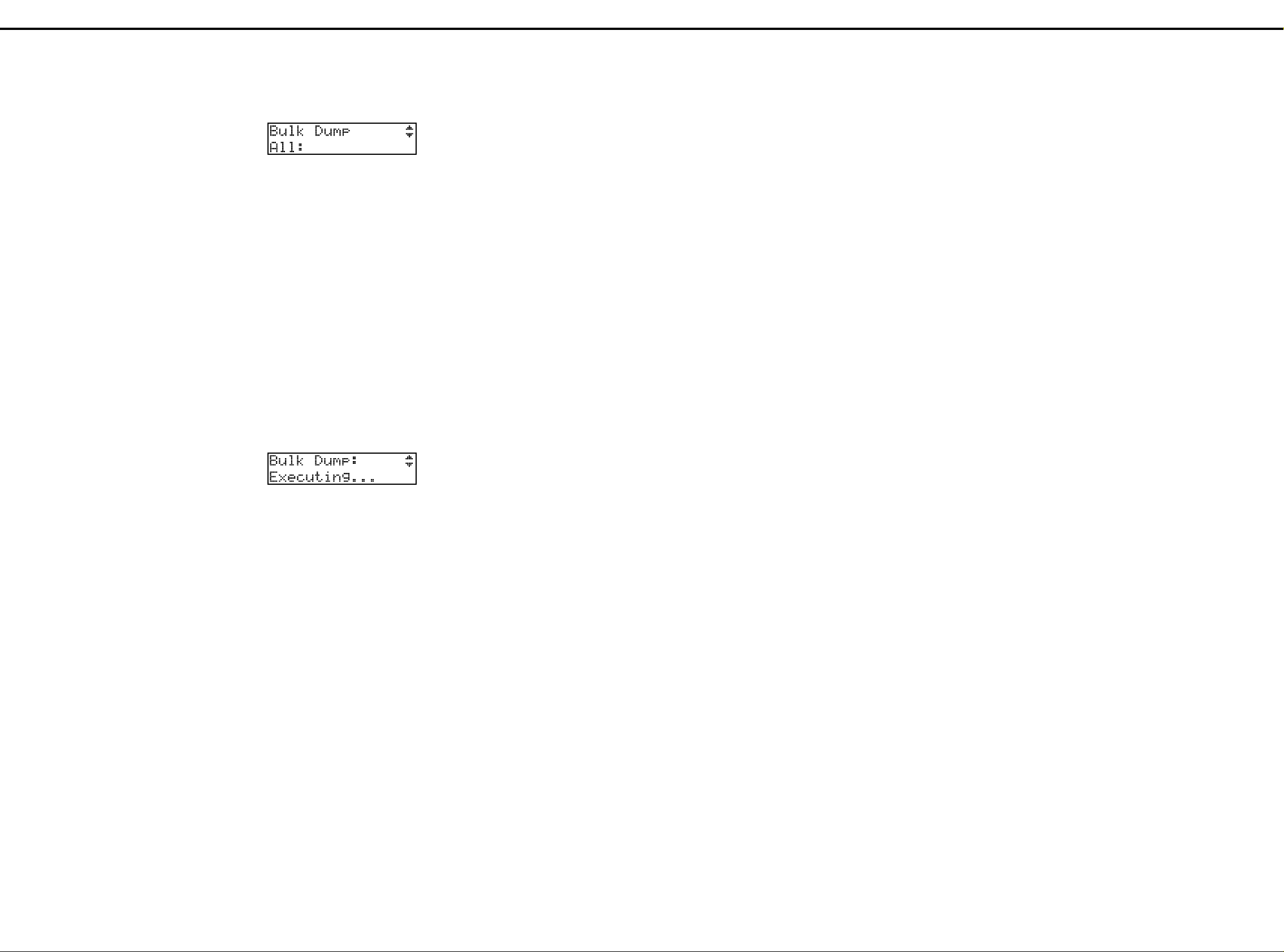
2.3 P ress the [ENTER] or [ ] button.
2.4 Using the [ ] and [ ] buttons, display "Bulk Dump".
2.5 Using the [+] and [-] buttons, select the information to
be output.
ALL:
Regist:
Orch:
System:
2.6 After selecting Regist or Orch, select the information to
be output by using the [<] , [>] , [+] and [-] buttons.
2.7 O nc e the information is selected, star t the recording on
the sequencer.
2.8 P ress the [ENTER] button and the information is output
to the [MIDI OUT].
▲
outputs all VK-77 information.
outputs the information stored in the registration.
The desired registration can be selected (see step
2.6 below).
outputs the orchestral voice settings.
Desired setting can be selected (see step 2.6 below).
outputs the VK-77 system settings.
▼
▼
3. [ENTER] または [▼] を押します。
4. [ ▲] [▼] を押して、ディスプレイに Bulk
Dump を表示させます。
5. [ +] [−]を押して出力したい情報を選びます。
ALL:
VK −77のすべての情報を出力します。
Regist:
レジストレーションに記憶された情報を出力します。
送信したいレジストレーションを選ぶことができま
す。
Orch:
オーケストラ・ボイスの設定を出力します。
送信したい設定を選ぶことができます。
System:
VK −77のシステム設定を出力します。
6. Regist、または Orch を選択したときは、
[<] [>]や[+] [−]
選びます。
7. 保存したい情報が決まったら、シーケンサの録音をス
タートさせます。
8. [ENTER] を押します。
保存したい情報が MIDI OUT 端子から出力され
ます。
を押して出力したい設定を
Messages
Wheel Brake
This is displayed when the wheel brake is in effect. If the
organ voice does not sound, it is possible that the wheel
brake has been left on. Check that this message is shown
in the display, and turn off the wheel brake. → Owner's
Manual p. 54, 60
Pedal Keyboard Ready
This message will appear when the power of the VK-77 is
turned on if a pedal keyboard unit (PK-7, PK-5 etc.) is
connected correctly. If this message does not appear even
though a pedal keyboard unit is connected, turn off the
power of the VK-77, and check the cable connections and
the position of the PEDAL KEYBOARD select switch.
→
Owner's Manual p.23, 24
Thru Excl: Press [EXIT] to Cancel
Since a large system exclusive message is being "thru'ed,"
the VK-77 has temporarily suspended operation. Either
wait until the system exclusive message has finished being
thru'ed, or press [EXIT] to abort the "Thru." If the Thru is
aborted, the SYSTEM MIDI menu → MIDI Thru setting will
automatically be set to On (w/o SysEx), and system
exclusive messages will stop being thru'ed. → Owner's
Manual p. 74
Error messages
Messages That Appear When the Power is
◎
Turned On
Battery Low!
Cause: The internal backup battery (which maintains the
Action: Contact your dealer or a nearby Roland Service
registrations, orchestral voices, and system settings
that you make) has run down.
Center to have the battery replaced.
メッセージ
メッセージ
メッセージメッセージ
Wheel Brake
ホイール・ブレーキが効いているとき表示されます。オル
ガン・ボイスの音が鳴らないときは、ホイール・ブレーキ
が効き続けていることが考えられます。このメッセージが
表示されていることを確認して、ホイール・ブレーキを解
除してください。→取扱説明書
P.54、60
Pedal Keyboard Ready
の電源をオンにしたとき、ぺダル鍵盤ユニット
VK-77
(
PK-7、PK-5
メッセージが表示されます。ペダル鍵盤ユニットを接続し
ているのにメッセージが表示されないときは、
源をオフにして、ケーブルの接続や
セレクト・スイッチの位置を再度確認してください。→取
扱説明書
など)が正しく接続されていると、この
VK-77
PEDAL KEYBOARD
P.23、24
Thru Excl: Press [EXIT] to Cancel
大きなシステム・エクスクルーシブ情報をスルーしている
ため、本体が待機状態です。
システム・エクスクルーシブ情報がスルーし終わるまで待
つか、[
ルーを中断すると、
が自動的にOn(
クルーシブ情報をスルーしなくなります。→取扱説明書
P.74
エラー・メッセージ
エラー・メッセージ
エラー・メッセージエラー・メッセージ
◎電源を入れた時に出るメッセージ
◎電源を入れた時に出るメッセージ
◎電源を入れた時に出るメッセージ◎電源を入れた時に出るメッセージ
]を押してスルーを中断してください。ス
EXIT
SYSTEM MIDI
w/o SysEx
メニュー→
)になり、システム・エクス
MIDI Thru
Battery Low!
原因: 本体内のバックアップ・バッテリー(作ったレジス
対処: お買い上げ店または最寄りのローランド・サービス
トレーションやオーケストラ・ボイス、システムの
設定を保持するための電池)が消耗しています。
に電池の交換を依頼してください。
の電
2.9 When the data is transferred to the sequencer, the LCD
displays "Complete".
Stop the sequencer.
2.10Press the [EXIT] button twice, or press the [EDIT]
button.
The [EDIT] indicator turns off and the VK-77 exits the
edit mode.
•
Reloading saved data
To load the data saved on the sequencer back to the VK-77,
first connect the [MIDI OUT] of the VK-77 to the [MIDI IN] of
the sequencer, and [MIDI IN] of the VK-77 to the [MIDI OUT]
of the sequencer, and then play the sequencer.
ERROR MESSAGES /エラーメッセージ
/エラーメッセージ
/エラーメッセージ/エラーメッセージ
List of messages/error messages
The display of the VK-77 will occasionally show messages
regarding a special operation, or error messages that indicate
that an operation was incorrect or could not be performed. This
section explains the meaning of each message/error message,
and describes the action that you should take. Carefully read
the explanation and take the appropriate measures.
9. データの送信が終わると、ディスプレイには
「Complete.」と表示されます。
シーケンサをストップしてください。
10.[EXIT] を2回、または [EDIT] を押します。
EDIT] のインジケータが消灯(オフ)になり、
[
エディット・モードが終了します。
● MIDI
●MIDI データを受信するには
●MIDI● MIDI
シーケンサに記録したデータを VK −77に戻すときには、
VK −77の MIDI OUT をシーケンサの MIDI IN
に、VK −77の MIDI IN をシーケンサの MIDI
OUT に接続してシーケンサを再生します。
メッセージ/エラー・メッセージ一覧
メッセージ/エラー・メッセージ一覧
メッセージ/エラー・メッセージ一覧メッセージ/エラー・メッセージ一覧
VK-77
セージが、操作を間違えたり操作が正しく実行できなかったと
きにはエラー・メッセージが表示されます。ここでは、メッ
セージ/エラー・メッセージの意味とその対処方法について説
明しています。説明をよく読んで対処してください。
データを受信するには
データを受信するにはデータを受信するには
のディスプレイには、特別な動作をするときにはメッ
MIDI-Related messages
◎
MIDI Buffer Full!
Cause: More MIDI data was received in a short time than the
Action: Reduce the amount of MIDI data that is being
VK-77 was able to process.
transmitted to the VK-77.
MIDI Communication Error!
Cause: It is possible that a MIDI cable is disconnected or
Action: Check that the MIDI cables are connected correctly
broken.
and are not broken.
Sys Excl: Check Sum Error!
Cause: A system exclusive message with an incorrect check
Action 1:Check the data that is being transmitted from the
Action 2:If the check sum is correct, use as short a MIDI cable
Action 3:If the check sum is correct and there is another MIDI
sum was received.
other device to the VK-77. If the data was incorrect,
correct it and try the operation once again.
as possible, and try the operation once again.
device (such as a device with MIDI Thru
functionality) between the transmitting device and the
VK-77, disconnect that device, connect the
transmitting device directly to the VK-77, and try the
operation once again. If the same message appears
in spite of this, contact your dealer or a nearby
Roland Service Center.
Sys Excl: Rx Data Error!
Cause: Sys tem exclusive data is not being received
Action: Check the data that is being transmitted and the
correctly.
settings of the transmitting device.
MIDI
◎◎◎◎
に関するメッセージ
に関するメッセージ
に関するメッセージに関するメッセージ
MIDI Buffer Full!
原因: VK-77 が多量の
対処: 送信する
め処理できません。
MIDI
データを短時間で受信したた
MIDI
データの量を減らしてください。
MIDI Communication Error!
原因: MIDIケーブルが抜けているか、断線している可能性
対処: MIDIケーブルが正しく接続されているか、断線して
があります。
いないかを確認してください。
Sys Excl: Check Sum Error!
原因: 受信したシステム・エクスクルーシブ情報のチェッ
対処1:他の機器から
対処2:チェック・サムが正しい場合、できるだけ短い別の
対処3:チェック・サムが正しく、送信側の機器と
ク・サムが間違っています。
ださい。間違っている場合は、修正して再度操作し
てください。
ケーブルを使用して、再度操作してください。
MIDI
間に別の
るもの)を接続している場合、その
して送信側の機器と
接続し、再度操作してください。それでも同じメッ
セージが表示される場合は、お買い上げ店または最
寄りのローランド・サービスにご連絡ください。
MIDI
に送信したデータを確認してく
VK-77
機器(例えば、
VK-77をMIDI
スルー機能のあ
MIDI
ケーブルで直接
MIDI
VK-77
機器を外
Sys Excl: Rx Data Error!
原因: システム・エクスクルーシブ情報が正しく受信され
対処: 送信した機器の設定や、送信したデータを確認して
ていません。
ください。
の
Memory-Related messages
◎
Memory Damaged!
Cause: The backup battery has run down, causing the
Action: Contact your dealer or a nearby Roland Service
internal data to be lost.
Center to have the battery replaced.
MIDI
◎◎◎◎
に関するメッセージ
に関するメッセージ
に関するメッセージに関するメッセージ
Memory Damaged!
原因: バックアップ・バッテリーの消耗により、内部デー
対処: お買い上げ店または最寄りのローランド・サービス
タが失われました。
に電池の交換を依頼してください。
13
Page 14
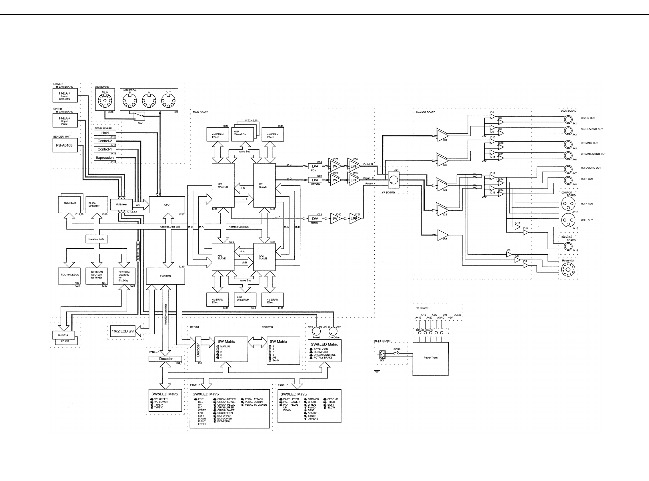
Apr,1999VK-77
11112
AAAA
23
22
BLOCK DIAGRAM /ブロック図
34
33
45
44
/ブロック図
/ブロック図/ブロック図
56
55
BBBB
CCCC
DDDD
EEEE
FFFF
GGGG
HHHH
67
66
78
77
89
88
910
99
10 11
1010
11 12
1111
12 13
1212
13 14
1313
14 15
1414
15 16
1515
16 17
1616
17 18
1717
18 19
1818
19 20
1919
20 21
2020
21 22
2121
22 23
2222
23 24
2323
24 25
2424
25 26
2525
26 27
2626
27 28
2727
28
2828
IIII
JJJJ
KKKK
LLLL
MMMM
NNNN
OOOO
PPPP
QQQQ
14
RRRR
SSSS
TTTT
UUUU
Page 15
Apr,1999 VK-77
11112
AAAA
23
22
34
33
45
44
WIRING DIAGRAM /配線図
BBBB
CCCC
DDDD
ANALOG
EEEE
FFFF
GGGG
PANEL A
W31
HHHH
IIII
CN9(53254-13)
CN8(FPC-22)
W30
CN13(FPC-22)
JJJJ
PANEL B
KKKK
LLLL
MMMM
LCD
CN15(53254-1)
PANEL C
NNNN
OOOO
PPPP
BENDER
QQQQ
RRRR
SSSS
TTTT
56
55
/配線図
/配線図/配線図
W28
67
66
CN24(51048-7) CN25(51048-7)
CN21(51048-7) CN22(51048-7)
CN16(51048-6) CN17(51048-6)
CN5(PH-4)
CN30(PH-7)
CN1(PH-6)
CN3(PH-14)
CN14(53253-6)
CN26(XH-10)
CN11(FPC-24)
CN10(FPC-22)
CN12(53254-9)
CN14(51048-4)
CN14(PH-4)
PHONES
78
77
89
88
W24
VR
CN11(PH-13)
CN10(PH-14)
CN9(PH-6)
W24
W24
W23
W21
W20
W18
W19
W27
W32
W29
W14
W11
910
99
10 11
1010
JACK
CN3(53254-9)
Regist L
CN2(53254-11)
W13
CN10(FPC-22)
CN1(52147-4)
W17
CN22(PH-13)
CN12(53253-6)
CN8(FPC-14)
CN2(IL-S-5)
W7
11 12
1111
12 13
1212
CN27(52147-7)
13 14
1313
14 15
1414
15 16
1515
MIDI
CN32(52147-8) CN31(51048-8)
CANNON
W15
CN4(53254-8) CN6(53254-8)
CN8(51048-10)
Regist R
CN1(53254-10)
CN13(53253-11)
CN5(53254-10)
W16
CN11(52147-10)
MAIN BOARD
CN16(FPC-16) CN19(FPC-18)CN17(FPC-16) CN18(FPC-16)
W5
W7
UPPER KEYBOARD(w AfterTouch)
LOWER KEYBOARD
16 17
1616
W22
W26
UPPER H_BAR
CN1(51048-14)
W9
CN13(52147-14)
W6
17 18
1717
18 19
1818
CN33(PH-5)
PEDAL
LOWER H_BAR
CN2(51048-13)
CN14(52147-13)
19 20
1919
W10
CN7(XH-6)
20 21
2020
W12
W2
W1
21 22
2121
CN19(PH-5)
CN18(PH-7)
CN5(XH-10)
22 23
2222
PS BOARD
CN6(XH-6)
CN4(VH-5)
CN16(FPC-24)
23 24
2323
INLET P.S
TRANS
HP335 W4
24 25
2424
W4
PANEL D
W1 :WIRING 6x350-P2.5-XHP-XHP-F
W2 :WIRING 10x750-P2.5-XHP-XHP-F
W3 :HP-335 W4
W4 :VK-77 WIRING W1
W5 :FUJI CARD 16x800-A6.0BBR-P1.25-HBL10
W6 :FUJI CARD 18x800-A6.0BBR-P1.25-HBL10
W7 :FUJI CARD 16x550-A6.0BBR-P1.25-HBL10
W9 :RIBBON CABLE 14x350-P2.0
W10:RIBBON CABLE 13x500-P2.0
W11:RIBBON CABLE 4x500-P2.0
W12:5x250-P2.0-PH-PH-F
W13:11x450-P2.0-51065-51065-F
W14:9x350-P2.0-51065-51065-F
W15:8x100-P2.0-51065-51065-F
W16:10x100-P2.0-51065-51065-F
W17:13x450-P2.0-PH-PH-F
W18:6x300-P2.0-PH-PH-F
W19:14x300-P2.0-PH-PH-F
W20:7x800-P2.0-PH-PH-F
W21:4x250-P2.0-PH-PH-F
W22:RIBBON CABLE 8x50-P2.0
W23:RIBBON CABLE 6x150-P2.0
W24:RIBBON CABLE 7x150-P2.0
W26:RIBBON CABLE 10x100-P2.0
W27:6x350-P2.0-51065-51065-F
W28:FUJI CARD 14x800-A6.0BBR-P1.25-HBL10
FUJI CARD 14x800-A6.0BBR-P1.25-HBL10-S-C
W29:FUJI CARD 24x350-A6.0BBR-P1.25-HBL10
FUJI CARD 24x350-A6.0BBR-P1.25-HBL10-S-C
W30:FUJI CARD 26x200-A6.0BBR-P1.25-HBL10
W31:13x500-P2.0-51065-51065-F
W32:FUJI CARD 22x800-A6.0BBR-P1.25-HBL10
25 26
2525
(Serial No. ~ZM30229)
(Serial No. ZM30300~)
(Serial No. ~ZM30229)
(Serial No. ZM30300~)
26 27
2626
01781934
01781945
01349990
01781967
01780956
01780967
01677845
01782056
01782067
00789790
01781978
01781989
01781990
01782001
01782012
01782078
01782023
01782089
01782034
01782090
01782123
01782134
01782145
00890390
01782045
01781001
01902967
01780978
01902956
01780990
01782112
01780989
27 28
2727
28
2828
UUUU
15
Page 16

Apr,1999VK-77
11112
AAAA
23
22
CIRCUIT DIAGRAM /回路図
MAIN BOARD
34
33
45
44
BBBB
CCCC
DDDD
EEEE
FFFF
GGGG
HHHH
56
55
/回路図
/回路図/回路図
67
66
78
77
89
88
910
99
10 11
1010
11 12
1111
12 13
1212
13 14
1313
14 15
1414
15 16
1515
16 17
1616
17 18
1717
18 19
1818
19 20
1919
20 21
2020
21 22
2121
22 23
2222
23 24
2323
24 25
2424
25 26
2525
26 27
2626
27 28
2727
28
2828
IIII
JJJJ
KKKK
LLLL
MMMM
NNNN
OOOO
PPPP
QQQQ
16
RRRR
SSSS
TTTT
UUUU
Page 17

Apr,1999 VK-77
11112
AAAA
23
22
34
33
MAIN BOARD CPU
BBBB
CCCC
DDDD
EEEE
FFFF
to
ANALOG BOARD
CN4
GGGG
to
HHHH
MIDI JACK BOARD
IIII
JJJJ
from
PS BOARD
CN6
KKKK
LLLL
VPP Ctrl
VPPCTRL
MMMM
NNNN
BATTERY
OOOO
DA11
PPPP
QQQQ
RB715F
12
C91
33/16
SYSTEM RESET
& XP MODE Ctrl
RRRR
SSSS
7
4
TTTT
CN12
53253-0610
CN11
52147-1010
FC[0..2]
CN7
B6B-XH-A
IC27C
TL062CPS
3
R87
76
10k
910
6
VCC
NC
R
S
NC
T
NC
NC
DLY
GND
IC12
M51953BFP
45
44
C473 100p
C472 100p
C474 100p
1
1
2
2
3
3
4
4
5
5
6
1
2
3
8
5
1
2
3
4
5
6
7
8
9
10
1
2
3
4
5
6
R60
1.5k
C102
0.1
C89
33/16
1
R61
10k
MIDI IN1
MIDI IN0CN8
XRSTA
MIDI OUT
FC3
FC2
FC1
FC0
FC[0..2]
2
3
8
4
C106
0.1
R51
100k
2
BT1
1
CR2450BH
IC16A
TC74HC4050AF
IC16B
TC74HC4050AF
C437
680p
C93
1/50
R206
4.7k
R211
4.7k
C187
0.1
C188
33/16
C182
0.1
C181
33/16
Q5
RN2421
2
3
XRSTA
XRSTB
C115
1.0
C92
33/16
32
54
XRSTA
XRSTB
11 12
14 15
6
1
2
3
4
5
6
7
8
9
10
1
2
3
4
5
6
R50
10k
IC16C
TC74HC4050AF
IC16D
TC74HC4050AF
56
55
C174
0.1
C438
33/16
C440
0.1
C439
33/16
VPP
6
5
1
IC27A
TL062CPS
IC16E
TC74HC4050AF
IC16F
TC74HC4050AF
C275
1200p
67
66
C180 470p
C179 470p
C178 470p
C177 470p
R223 100
R224 100
R225 100
MPX[0..2]
BNDCLK
BNDCLK
C475
470p
AN[0..7]
18
XDEND
27
36
DTR
45
VPPCTRL
7
IC27B
TL062CPS
R52
1k
BATTCHK
C90
100p
1
8
IC16G
TC74HC4050AF
MCTRL
MCTRL
XSLVRST
XSLVRST
MPX[0..2]
AN[0..7]
BATTCHK
C130
0.1
78
77
C148 33/16
C147 0.1
C145 0.1
C144 0.1
C143 0.1
C142 0.1
C141 0.1
C140 0.1
RDYCTRL
FDCRST
2
1
3
Q1
DTA124EK
C77
100p
RA24
10k
C85
12p
C86
10p
XRSTA
89
88
82
R48
81
10k
80
R49
10k
110
PB11
109
MIDII1
MIDIO0
108
107
MIDII0
105
ROTSENS
104
FAST
SLOW
103
MPX2
102
101
MPX1
MPX0
100
98
97
R81
10k
R82
10k
65
64
XDEND
AN7
95
94
AN6
AN5
93
92
AN4
90
AN3
89
AN2
88
AN1
87
AN0
86
85
C103
0.1
91
73
1
74
4
X2
MA406
20.000MHz
R69
0
79
C97
NIU
9
XSSC0CS
XSSC1CS
10
12
XECS11
XFDCCS
13
IC24B
TC74HC21AF
C419
1
0.1
2
XWRL
TC7S02F
910
99
7
1
4
7
7
8
8
9
7
5
3
0
5
3
4
9
V
V
V
V
V
V
V
V
P
C
C
C
C
C
C
P
C
C
C
C
C
PA8/BREQ
PA7/BACK
WAIT/CS7
CASL/CS3
CASH/CS1
PA9/AH/IREQOUT
TP15/IREQ7
TP14/IREQ6
TP13/SCK1/IREQ5
TP12/SCK0/IREQ4
DREQ1/IREQ3
DACK1/IREQ2
DREQ0/IREQ1
DACK0/IREQ0
V
V
V
V
V
V
V
S
S
S
S
S
S
S
S
S
S
S
S
S
S
1
2
3
4
5
6
3
2
2
1
0
2
1
IC50
TC74VHC245AF
D7
D6
D5
D4
D3
D2
D1
D0
8
4
IIC DAUGHTER BOARD
C
C
C
A0(HBS)
PA5/WRH
WDTOVF
RAS/CS5
V
V
S
S
S
S
7
9
2
6
A[0..9]
BD[0..7]
to
V
S
S
MD2
MD1
MD0
TXD1/PB11/TP11
RXD1/PB10/TP10
TXD0/PB9/TP9
RXD0/PB8/TP8
PB7/TOCXB4
PB6/TOCXA4
PB5/TP5/TIOCB4
PB4/TP4/TIOCA4
PB3/TP3/TIOCB3
PB2/TP2/TIOCA3
PB1/TP1/TIOCB2
PB0/TP0/TIOCA2
PA11/TIOCB1
PA10/TIOCA1
AN7/PC7
AN6/PC6
AN5/PC5
AN4/PC4
AN3/PC3
AN2/PC2
AN1/PC1
AN0/PC0
AVREF
AVCC
AVSS
EXTAL
XTAL
RES
5
3IC47
IC17
47
A21
46
A20
45
A19
44
A18
42
A17
41
A16
39
A15
38
A14
37
A13
36
A12
35
A11
34
A10
33
A9
32
A8
30
A7
29
A6
28
A5
27
A4
26
A3
25
A2
24
A1
23
21
AD15
20
AD14
19
AD13
18
AD12
17
AD11
16
AD10
14
AD9
13
AD8
11
AD7
10
AD6
9
AD5
8
AD4
7
AD3
6
AD2
5
AD1
4
AD0
58
57
WRL
59
RD
62
60
78
56
55
CS6
54
53
CS4
51
50
CS2
49
48
CS0
63
2
1
112
111
69
68
67
66
76
NMI
71
CK
HD6437034F20
1
0
6
9
8
7
6
5
4
3
2
19
1
10 11
1010
18
27
36
45
18
27
36
45
18
27
36
45
18
27
36
45
18
27
36
45
18
27
36
45
18
27
36
45
18
27
36
45
18
27
36
45
C292
0.1
A8
A7
A6
A5
A4
A3
A2
A1
G
DIR
45
36
27
18
45
36
27
18
A[0..9]
BD[0..7]
XWRH
XWRL
XRD
VPPCTRL
FC3
XWAIT
XCS6
XCS4
XCS2
DTR
XGAIRQ
XXP0IRQ
XFDCIRQ
XXP3IRQ
XFDCDREQ
XXP1IRQ
XXP2IRQ
XIRQ0
20MHZ
V
C
C
G
N
D
RA111 NIU
RA112 NIU
CN25
1
2
3
4
5
6
7
8
9
10
11
12
13
14
15
16
17
18
19
20
NIU
RA9
47
RA10
47
RA11
47
RA12
47
RA13
47
R85
R86
47
47
RA14
47
RA15
47
RA16
47
RA17
47
2
0
B8
B7
B6
B5
B4
B3
B2
B1
1
0
1
2
3
4
5
6
7
8
9
10
11
12
13
14
15
16
17
18
19
20
11 12
1111
A21
A20
A19
A18
A17
A16
A15
A14
A13
A12
A11
A10
A9
A8
A7
A6
A5
A4
A3
A2
A1
A0
D15
D14
D13
D12
D11
D10
D9
D8
D7
D6
D5
D4
D3
D2
D1
D0
RA113
10k
11
12
13
14
15
16
17
18
XECS11
XRD
PB11
D1
D3
D5
D7
A0
A2
XWRL
XIRQ0
D0
D2
D4
D6
XRSTA
A1
MCTRL
12 13
1212
A18
A17
18
A16
27
A15
36
A14
45
A13
18
A12
27
A11
36
A10
45
A9
18
A8
27
A7
36
A6
45
A5
18
A4
27
A3
36
A2
45
A1
1 2
A21
3
A20
4
A19
5
A18
6
A17
7
A16
8
A15
9
A14
1 2
A13
3
A12
4
A11
5
A10
6
A9
7
A8
8
A7
9
A6
1 2
3
4
A5
5
A4
6
A3
7
A2
8
A1
9
A0
1 2
D15
3
D14
4
D13
5
D12
6
D11
7
D10
8
D9
9
D8
1 2
D7
3
D6
4
D5
5
D4
6
D3
7
D2
8
D1
9
D0
18
27
36
45
XXP0IRQ
XXP1IRQ
XXP2IRQ
XXP3IRQ
R53 10k
R65 10k
R83 10k
1 8
R84 10k
2 7
RA25
3 6
10k
4 5
C175
0.1
5
XRSTA
1
2
RAMCS
3
IC13
TC7S00F
1
23456789
BD7
BD6
BD5
BD4
BD3
BD2
BD1
BD0
C420
NIU
C421
NIU
13 14
1313
BA18
BA17
BA16
BA15
BA14
BA13
BA12
BA11
BA10
BA9
BA8
BA7
BA6
BA5
BA4
BA3
BA2
BA1
RA18
10k
RA19
10k
RA20
10k
RA21
10k
RA22
10k
RA23
10k
XRD
XWRL
4
62
IC22C
NIU
A1
A0
BD7
BD6
BD5
BD4
BD3
BD2
BD1
BD0
FDCRST
XRD
XWRL
XFDCCS
XFDCIRQ
XFDCDREQ
XDEND
DTR
4
C96
NIU
C95
1
NIU
X1
NIU
R215
0
R216
0
RA117
0
RA114
0
RA115
0
RA116
0
XROMCS
XWRH
XRD
XRSTA
BA18
BA17
BA16
BA15
BA14
BA13
BA12
BA11
BA10
BA9
BA8
BA7
BA6
BA5
BA4
BA3
BA2
BA1
A17
A16
A15
A14
A13
A12
A11
A10
A9
A8
A7
A6
A5
A4
A3
A2
A1
A17
A16
A15
A14
A13
A12
A11
A10
A9
A8
A7
A6
A5
A4
A3
A2
A1
XRSTA
XWRH
XRD
XRSTA
XWRL
XRD
R209
NIU
NIU
IC22D
NIU
IC18
LH28F400SUT-60
9
8
19
18
17
16
15
14
13
12
3
4
5
6
21
20
7
22
1
40
39
37
36
24
2
14 15
1414
20
A17
*/DQ15
55
A16
DQ14
3
A15
DQ13
4
A14
DQ12
5
A13
DQ11
6
A12
DQ10
7
A11
DQ9
8
A10
DQ8
9
A9
DQ7
10
A8
DQ6
21
A7
DQ5
22
A6
DQ4
23
A5
DQ3
24
A4
DQ2
25
A3
DQ1
26
A2
DQ0
27
A1
31
A0
NC
22
24
2
31
3
28
4
25
23
26
27
5
6
7
8
9
10
11
12
30
29
2
31
3
28
4
25
23
26
27
5
6
7
8
9
10
11
12
22
30
29
24
RS1
RS0
D7
D6
D5
D4
D3
D2
D1
D0
RESET
RD
WR
CS
IRQ
DREQ
DACK
DEND
8"/5"
EXTAL1
XTAL1
EXTAL2
XTAL2
1/2EX1
XTALSEL
NC
NC
NC
NC
NC
CE
WE
OE
BYTE
RY/BY
RP
IC19
A16
A15
A14
A13
A12
A11
A10
A9
A8
A7
A6
A5
A4
A3
A2
A1
A0
CE1
CE2
R/W
OE
TC551001BFL-70L
IC20
A16
A15
A14
A13
A12
A11
A10
A9
A8
A7
A6
A5
A4
A3
A2
A1
A0
CE1
CE2
R/W
OE
TC551001BFL-70L
C192
NIU
2
5
V
V
C
C
C
C
1
2
V
V
V
V
S
S
S
S
S
S
S
S
1
2
3
4
1
1
2
0
1
3
NC
NC
NC
NC
NC
VPP
VCC
VCC
GND
GND
I/O8
I/O7
I/O6
I/O5
I/O4
I/O3
I/O2
I/O1
NC
VDD
GND
I/O8
I/O7
I/O6
I/O5
I/O4
I/O3
I/O2
I/O1
NC
VDD
GND
4
4
4
4
5
6
V
V
C
C
C
C
3
4
RDATA
INDEX
READY
WDATA
WGATE
HLOAD
SFORM
V
V
V
S
S
S
S
S
S
5
6
7
4
4
4
1
2
9
19
28
29
30
56
32
13
34
54
18
14
8
4
15 16
1515
52
D15
50
D14
48
D13
D12
46
D11
42
D10
40
38
D9
36
D8
D7
51
49
D6
47
D5
45
D4
41
D3
39
D2
D1
37
D0
35
1
2
11
12
15
16
C169
VPP
17
33/16
C167
0.1
43
44
33
53
C168
0.1
D15
21
20
D14
19
D13
18
D12
D11
17
15
D10
D9
14
D8
13
1
32
C104
0.1
16
D7
21
D6
20
19
D5
D4
18
D3
17
D2
15
D1
14
D0
13
1
32
C105
16
0.1
R226
NIU
IC22A
C194
NIU
NIU
17
J8
NIU
C94
NIU
C109
NIU
C107
NIU
IC21
C108
NIU
XRDATA
35
XINDEX
34
33
XTRK0
TRK0
XWPRT
32
WPRT
31
XRDY
XINP
30
INP
48
XWDATA
XWGATE
47
XSTEP
50
STEP
XHDIR
51
HDIR
52
XHSEL
53
HSEL
58
DS3
57
DS2
56
DS1
XDS0
55
DS0
63
MON3
62
MON2
61
MON1
60
MON0
38
NC
43
NC
29
28
IFS
27
NUM2
26
NUM1
V
V
S
S
S
S
8
9
5
5
6
4
9
4
16 17
1616
35
J3
NIU
R212
10k
RA30
10k
R111
10k
1 2
45
36
27
18
RA28
10k
IC22B
NIU
XRDY
XRDATA
XWPRT
XTRK0
XINP
R64 NIU
R63 NIU
XDS0
XDS3XDS3
XDS0
RDYCTRL
J2
NIU C119
C118
NIU
NIU
C124
NIU
C127
NIU
17 18
1717
3
4
5
6
7
8
9
R110 NIU
R109 NIU
R108 NIU
R107 NIU
R106 NIU
1
2
IC14
NIU
1
2
C120
NIU
C123
NIUC121
C126
NIU
C129
NIU
RA27
10k
18
27
36
45
A[0..13]
D[0..15]
XWRL
XRD
IC67
TC7W126FU
RA26
NIU
C116
NIU
5
4
IC15
3
NIU
C117
NIU
5
4
3
NIU
C122
NIU
C125
NIU
C128
NIU
18 19
1818
A21
A20
A19
A5
A4
A3
A2
A1
A0
D7
D6
D5
D4
D3
D2
D1
D0
XRD
XWRL
XWAIT
XCS2
XCS4
XCS6
XGAIRQ
XECS11
XXP3CS
XXP1CS
XXP2CS
XFDCCS
XSSC1CS
XXP0CS
XSSC0CS
RAMCS
XROMCS
XSSC0IRQ
XSSC1IRQ
XINDEXINT
20MHZ
10MHZ
XRSTA
R89
0
R88
0
C193
NIU
XXP3CS
XXP2CS
XXP1CS
XXP0CS
A[0..13]
D[0..15]
XSSC1CS
XSSC0CS
XSSC1IRQ
XSSC0IRQ
10MHZ
J13
NIU
J14
NIU
C430
0.1
8
5
3
A2
Y2
V
2
6
C
A1
Y1
C
7
G
G2
N
1
G1
D
4
1 8
FDS1
2 7
FDS2
3 6
FDS0
4 5
FDS3
FDS1
J6
NIU
FDS0
J7
NIU
34PIN
J4
NIU
XRDY
J5
NIU
16PIN
XINP
XINDEX
FDS1
16PIN
XHDIR
XSTEP
XWDATA
XWGATE
XTRK0
XWPRT
XRDATA
XHSEL
19 20
1919
23
22
21
20
19
18
17
16
15
14
13
12
11
10
9
8
7
34
35
36
31
32
37
41
39
38
24
55
54
51
50
49
48
47
46
45
44
43
42
58
57
56
27
30
26
C111
NIU
XPRD
J16
0
20MHZ
A21
A20
A19
A5
A4
A3
A2
A1
A0
D7
D6
D5
D4
D3
D2
D1
D0
XRD
XWRH
XWRL
XDREQ
XDACK
WAIT OUT
CS6
CS4
CS2
XIREQ
ECS11
ECS10
ECS9
ECS8
ECS7
ECS6
ECS5
ECS4
ECS3
ECS2
ECS1
ECS0
EXTINT2
EXTINT1
EXTINT0
CLK IN
CLK OUT
RESET
XPRD
XINP
FDS3
XINDEX
FDS0
FDS1
FDS2
16PIN
XHDIR
XSTEP
XWD ATA
XWGATE
XTRK0
XWPRT
XRDATA
XHSEL
34PIN
V
D
D
V
S
S
13
D4
12
D3
5
D2
4
D1
1
CLR
9
CK
IC70
NIU
R62
NIU
1
2
3
4
5
6
7
8
9
10
11
12
13
14
15
16
17
18
19
20
21
22
23
24
25
26
27
28
29
30
31
32
33
34
20 21
2020
C150 33/16
C149 0.1
C134 0.1
C133 0.1
C132 0.1
C131 0.1
IC10
5
7
2
9
V
V
D
D
D
D
V
V
S
S
S
S
5
8
3
0
V
C
C
G
N
D
CN5
DGND
HD STATUS
NC
IN USE
DGND
D SEL3
DGND
INDEX
DGND
D SEL0
DGND
D SEL1
DGND
D SEL2
DGND
MO
DGND
DIR SEL
DGND
STEP
DGND
WR D ATA
DGND
WR GATE
DGND
TRACK00
DGND
WR PRTCT
DGND
RD DATA
DGND
SIDE SEL
DGND
READY
NIU
2
9
4
0
1
6
8
M60205-0601FP
2
V
D
D
V
S
S
6
MIDI IN
4
WRHO
5
WRLO
25
WAIT IN
66
PORT7
65
PORT6
64
PORT5
63
PORT4
62
PORT3
61
PORT2
60
PORT1
59
PORT0
3
PWM 2
67
PWM 1
69
ENC B
68
ENC A
74
SS3
73
SS2
72
SS1
71
SS0
78
LS3
77
LS2
76
LS1
75
LS0
70
SSEN
81
LLCK
89
PD7
88
PD6
87
PD5
86
PD4
85
PD3
84
PD2
83
PD1
82
PD0
90
RS/CD
91
R/W
92
LE/RD
100
LCD 7
99
LCD 6
98
LCD 5
97
LCD 4
96
LCD 3
95
LCD 2
94
LCD 1
V
V
93
LCD 0
S
S
S
S
2
3
1
8
3
C477
NIU
15
4Q
10
3Q
7
2Q
2
1Q
1
14
4Q
11
2
3Q
6
2Q
3
1Q
IC71
NIU
to FDD UNIT
21 22
2121
MIDII0
R228
0
L1
L2
L3
L4
L5
L6
L7
N2012Z102
L8
L9
L10
L11
L12
L13
L14
L15
L16
L17
L18
L19
L20
L21
L22
L23
L24
L25
N2012Z102
J15
0
5
4
3
22 23
2222
6
LCDCONT
C476
NIU
IC24A
TC74HC21AF
LCDCONT
SS3
SS2
SS1
SS0
LS3
LS2
LS1
LS0
XSSEN
LLCK
PD7
PD6
PD5
PD4
PD3
PD2
PD1
PD0
XXP3CS
XXP2CS
XXP1CS
XXP0CS
5
4
2
1
23 24
2323
XXP0WAIT
XXP1WAIT
XXP2WAIT
XXP3WAIT
R57
47k
R58
10k
*ADDRESS MAP*
6100000h
43FFFFFh
4380000h
41FFFFFh
4180000h
417FFFFh
4100000h
23FFFFFh ECS3
2300000h
C159
1000p
C160
1000p
C158
1000p
L26
L27
L28
L29
L30
L31
L32
L33
N2012Z102
1
2
4
5
9
10
12
13
TC74VHC32AF
C163
1000p
C162
1000p
C161
1000p
Q6
2SC4116GR
IC26A
IC26B
IC26C
IC26D
2 3
1
C139
0.1
ECS11
IIC CN
*NIU*
G/A
ECS6
FDC
*NIU*
ECS5
KEY SCAN1
*NIU*
KEY SCAN0
61/61keys
XXP0WAIT
XXP1WAIT
XXP2WAIT
XXP3WAIT
1
23456789
C166
1000p
C165
1000p
C164
1000p
R68
1.5k
3
6
8
11
24 25
2424
RA29
10k
XPWR3
XPWR2
XPWR1
XPWR0
C156
0.01
C423
0.01
C154
0.01
IC24C
TC74HC21AF
C413
0.01
C414
0.01
C412
0.01
C422
0.01
C151
0.01
C155
0.01
R59
6.8k
C137
0.1
XPWR3
XPWR2
XPWR1
XPWR0
C37FFFFh6FFFFFFh
C300000h
C2FFFFFh
C280000h
C27FFFFh
C200000h
C0FFFFFh
C000000h
A27FFFFh
A200000h
A000000h
25 26
2525
C417
0.01
C416
0.01
C415
0.01
C157
0.01
C153
0.01
C152
0.01
C138
0.1
1
4
7
C418
0.01
ECS9
XP3
Slave
ECS8
XP1
Slave
ECS7
XP2
Slave
ECS4
XP0
Master
ECS1
SRAM
1M(8bit)x2
ECS0A1FFFFFh
FLASH
4M
C411
0.1
C410
33/16
C171
0.1
C170
33/16
C173
0.1
C172
33/16
1
4
7
IC26E
TC74VHC32AF
26 27
2626
C113
0.1
1
1
2
2
3
3
4
4
5
5
6
6
7
7
8
8
9
9
10
10
11
11
CN13
53253-1110
1
LS0
1
2
LS1
2
3
LS2
3
4
LS3
4
5
PD0
5
6
PD1
6
7
PD2
7
8
PD3
8
9
PD4
9
10
PD5
10
11
PD6
11
12
PD7
12
13
LLCK
13
14
SS0
14
15
SS1
15
16
SS2
16
17
SS3
17
18
XSSEN
18
19
XRSTA
19
20
20
21
21
22
22
23
23
24
24
CN10
IL-FPC-24ST-N
1
1
2
2
3
3
4
4
5
5
6
6
7
7
8
8
9
9
10
10
11
11
12
12
13
13
14
14
CN8
IL-FPC-14ST-N
C114
0.1
27 28
2727
to
REGISTRATION_L BOARD
CN2
to
PANEL_A BOARD
CN10
to
LCD UNIT
28
2828
UUUU
17
Page 18

Apr,1999VK-77
11112
AAAA
23
22
34
33
MAIN BOARD XP0,1
BBBB
CCCC
DDDD
EEEE
FFFF
GGGG
HHHH
IIII
JJJJ
KKKK
C256
33/16
C257
33/16
IC48B
TC7WU04F
IC48D
TC7WU04F
C287
0.1
IC49E
TC74HC02AF
C288
0.1
R148
1M
35
14
LLLL
MMMM
NNNN
12
RA119
OOOO
PPPP
10k
C252
33/16
C260
0.1
C259
0.1
C258
0.1
QQQQ
RRRR
45
44
IC49B
1
4
TC74HC02AF
5
6
7
R217
0
8
62
4
IC48C
TC7WU04F
XPCLK
IC48A
TC7WU04F
17
R128
100
R130
470
X3
24.576MHz
C250
C251
15p
15p
XRSTB
XRSTB
C286
NIU
IC40
TC514260DJS-60
EDMA7
39
I/O16
38
EDMA6
I/O15
37
EDMA5
I/O14
36
EDMA4
I/O13
34
EDMA3
I/O12
EDMA2
33
I/O11
32
EDMA1
I/O10
EDMA0
31
I/O9
10
I/O8
3
9
I/O7
4
8
I/O6
5
7
I/O5
6
5
I/O4
7
4
I/O3
8
3
I/O2
9
2
I/O1
1
VCC
6
VCC
20
VCC
21
VSS
35
VSS
40
VSS
56
55
D[0..15]
A[0..13]
XPRD
XXP0CS
XXP1CS
XXP0IRQ
XXP1IRQ
XXP0WAIT
XXP1WAIT
4
XPCLK
R129
0
C294
NIU
RA71
12
10k
26
A8
25
A7
24
A6
23
A5
22
A4
19
A3
18
A2
17
A1
16
A0
11
NC
12
NC
15
NC
30
NC
RAS
UCAS
LCAS
WE
OE
XPWR0
EDMA7
3
EDMA6
EDMA5
4
EDMA4
5
EDMA3
6
7
EDMA2
8
EDMA1
9
EDMA0
18
27
36
45
18
27
36
45
RA74 100
RA75 100
R131 100
X0RAS
14
28
X0CAS
29
X0EWE
13
27
67
66
C432
33p
XXP0WAIT
XXP0IRQ
RA72 100
RA73 100
18
EDMA7
27
EDMA6
EDMA5
36
EDMA4
45
EDMA3
18
27
EDMA2
36
EDMA1
45
EDMA0
78
77
24
A13
CA13
22
A12
CA12
19
A11
CA11
17
A10
CA10
18
A9
CA9
21
A8
CA8
23
A7
CA7
25
A6
CA6
26
A5
CA5
27
A4
CA4
28
A3
CA3
29
A2
CA2
31
A1
CA1
32
A0
CA0
D15
33
CD15
37
D14
CD14
D13
43
CD13
47
D12
CD12
51
D11
CD11
46
D10
CD10
42
D9
CD9
36
D8
CD8
35
D7
CD7
39
D6
CD6
45
D5
CD5
49
D4
CD4
48
D3
CD3
44
D2
CD2
38
D1
CD1
34
D0
CD0
55
AS
53
XXP0CS
CS
15
XPWR0
RW(WR)
16
XPRD
DS(RD)
52
WAIT
56
INT
58
CK
54
RESET
119
ED7
122
ED6
123
ED5
124
ED4
125
ED3
126
ED2
127
ED1
128
ED0
131
X0RAS
X0CAS
X0EWE
RAS
132
CAS
129
EWE
133
EA8
135
EA7
137
EA6
141
EA5
143
EA4
142
EA3
138
EA2
136
EA1
134
EA0
14
SYI
13
SYO
57
TEST
V
V
S
S
S
S
1
2
0
V
D
D
V
V
V
S
S
S
S
S
S
1
3
4
0
0
1
89
88
C254 33/16
C270 0.1
C450 0.1
C449 0.1
C448 0.1
C447 0.1
C274 0.1
C273 0.1
C271 0.1
C272 0.1
1
1
1
1
4
6
8
0
2
4
6
V
D
D
0
V
D
D
V
S
S
8
1
0
0
V
D
D
V
S
S
9
1
0
1
0
RA01-005
IC45
0
117
WREQ
V
118
D
WACK
D
61
WA23
62
WA22
64
WA21
63
WA20
65
WA19
66
WA18
87
WA17
84
WA16
82
WA15
78
WA14
76
WA13
74
WA12
72
WA11
69
WA10
67
WA9
68
WA8
71
WA7
73
WA6
75
WA5
77
WA4
79
WA3
83
WA2
86
WA1
85
WA0
91
WD15
95
WD14
99
WD13
104
WD12
107
WD11
103
WD10
98
WD9
94
WD8
93
WD7
97
WD6
102
WD5
106
WD4
105
WD3
101
WD2
96
WD1
92
WD0
116
WCS7
115
WCS6
114
WCS5
113
WCS4
112
WCS3
111
WCS2
109
WCS1
108
WCS0
88
WOE1
89
WOE0
11
OUTP2
9
OUTP1
12
OUTP0
8
WCKC
7
BCKC
6
SDOD
5
SDOC
4
WCKB
3
BCKB
2
SDIB
159
SDOB
158
WCKA
157
BCKA
151
SDIA5
152
SDIA4
153
SDIA3
154
SDIA2
155
SDIA1
156
SDIA0
144
SDOA5
145
SDOA4
146
SDOA3
147
SDOA2
148
SDOA1
149
SDOA0
V
V
V
V
S
S
S
S
S
S
S
S
10k
1
1
1
1
5
3
3
2
R136
0
9
0
1
R137
0
0
0
V
V
V
D
D
D
D
D
D
V
V
V
S
S
S
S
S
S
5
5
7
0
9
0
XP0
910
99
10
IC49C
TC74HC02AF
R143
R140 100
R138 100
RA76 100
10k
10k
IC49A
TC74HC02AF
IC49D
TC74HC02AF
WAA22
WAA21
WAA20
WAA19
WAA18
WAA17
WAA16
WAA15
WAA14
WAA13
WAA12
WAA11
WAA10
WAA9
WAA8
WAA7
WAA6
WAA5
WAA4
WAA3
WAA2
WAA1
WDA15
WDA14
WDA13
WDA12
WDA11
WDA10
WDA9
WDA8
WDA7
WDA6
WDA5
WDA4
WDA3
WDA2
WDA1
WDA0
R146 100
R147 100
8
9
100
F1T0B
F0T3B
BCKB
BCKA
F3T0A5
F3T0A4
F3T0A3
F3T0A2
F3T0A1
F3T0A0
1 8
F0T1A5
2 7
F0T1A4
3 6
F0T1A3
4 5
F0T1A2
F0T1A1
F0T1A0
4 5RA77
F0T1A5
3 6
F0T1A4
2 7
F0T1A3
1 8
F0T1A2
F0T1A1
F0T1A0
10 11
1010
2
1
3
12
13
11
WCKCD
WCKCD
BCKCD
SDOC0
SDOC0
F0T3B
BCKB
BCKA
11 12
1111
XWACS5
XWACS4
XWACS3
XWACS2
XWACS1
XWACS0
XWAOE0
SYSCLK
SDOD
SDOC1
F2T1B
F0T1A[0..5]
12 13
1212
SYSCKDABCKCD
SDOD
SDOC1
13 14
1313
WAA22
WAA21
WAA20
WAA19
WAA18
WAA17
WAA16
WAA15
WAA14
WAA13
WAA12
WAA11
WAA10
WAA9
WAA8
WAA7
WAA6
WAA5
WAA4
WAA3
WAA2
WAA1
WDA15
WDA14
WDA13
WDA12
WDA11
WDA10
WDA9
WDA8
WDA7
WDA6
WDA5
WDA4
WDA3
WDA2
WDA1
WDA0
R141 100
R210 100
R142 100
F2T1B
F1T0B
BCKB
BCKA
F0T1A5
F0T1A4
F0T1A3
F0T1A2
F0T1A1
F0T1A0
18
F1T2A5
27
F1T2A4
36
F1T2A3
45
F1T2A2
F1T2A1
F1T2A0
R134 100
R135 100
F1T2A5
F1T2A4
F1T2A3
F1T2A2
F1T2A1
F1T2A0
F1T2A[0..5]
F3T0A[0..5]
1 8
2 7
3 6
4 5
RA86
100
RA78
10k
R144
10k
R145
10k
F1T2A[0..5]
F3T0A[0..5]
14 15
1414
1
1
4
6
0
0
117
WREQ
V
V
V
118
61
62
64
63
65
66
87
84
82
78
76
74
72
69
67
68
71
73
75
77
79
83
86
85
91
95
99
104
107
103
98
94
93
97
102
106
105
101
96
92
116
115
114
113
112
111
109
108
88
89
11
9
12
8
7
6
5
4
3
2
159
158
157
151
152
153
154
155
156
144
145
146
147
148
149
WACK
WA23
WA22
WA21
WA20
WA19
WA18
WA17
WA16
WA15
WA14
WA13
WA12
WA11
WA10
WA9
WA8
WA7
WA6
WA5
WA4
WA3
WA2
WA1
WA0
WD15
WD14
WD13
WD12
WD11
WD10
WD9
WD8
WD7
WD6
WD5
WD4
WD3
WD2
WD1
WD0
WCS7
WCS6
WCS5
WCS4
WCS3
WCS2
WCS1
WCS0
WOE1
WOE0
OUTP2
OUTP1
OUTP0
WCKC
BCKC
SDOD
SDOC
WCKB
BCKB
SDIB
SDOB
WCKA
BCKA
SDIA5
SDIA4
SDIA3
SDIA2
SDIA1
SDIA0
SDOA5
SDOA4
SDOA3
SDOA2
SDOA1
SDOA0
V
S
S
D
D
D
D
D
D
V
V
V
V
V
S
S
S
S
S
S
S
S
S
S
1
1
1
1
1
1
2
3
3
5
0
1
0
9
0
XP1
15 16
1515
C255 33/16
C285 0.1
C454 0.1
C453 0.1
C452 0.1
C451 0.1
C284 0.1
C283 0.1
C281 0.1
C282 0.1
1
1
2
4
6
8
0
2
0
0
0
0
0
0
V
V
V
V
V
D
D
D
D
D
CA13
D
D
D
D
D
CA12
CA11
CA10
CA9
CA8
CA7
CA6
CA5
CA4
CA3
CA2
CA1
CA0
CD15
CD14
CD13
CD12
CD11
CD10
CD9
CD8
CD7
CD6
CD5
CD4
CD3
CD2
CD1
CD0
AS
CS
RW(WR)
DS(RD)
WAIT
INT
CK
RESET
ED7
ED6
ED5
ED4
ED3
ED2
ED1
ED0
RAS
CAS
EWE
EA8
EA7
EA6
EA5
EA4
EA3
EA2
EA1
EA0
SYI
SYO
TEST
V
V
V
V
V
V
V
V
S
S
S
S
S
S
S
S
S
S
S
S
S
S
S
S
1
3
4
5
5
7
8
9
1
0
0
1
0
9
0
1
0
RA01-005
16 17
1616
IC44
24
A13
22
A12
19
A11
17
A10
18
A9
21
A8
23
A7
25
A6
26
A5
27
A4
28
A3
29
A2
31
A1
32
A0
D15
33
37
D14
D13
43
47
D12
51
D11
46
D10
42
D9
36
D8
35
D7
39
D6
45
D5
49
D4
48
D3
44
D2
38
D1
34
D0
55
53
XXP1CS
15
XPWR1
16
XPRD
52
XXP1WAIT
56
XXP1IREQ
XPCLK
58
XSLVRST
54
RA89 100
RA90 100
119
1 8
122
2 7
123
3 6
124
4 5
125
1 8
126
2 7
127
3 6
4 5
128
X1RAS
131
132
X1CAS
129
X1EWE
133
135
137
141
143
142
138
136
134
RA87 100
RA88 100
R133 100
14
13
57
SYO
EDSA7
EDSA6
EDSA5
EDSA4
EDSA3
EDSA2
EDSA1
EDSA0
SYO
17 18
1717
WAA22
WAA21
WAA19
WAA20
WAA18
WAA9
WAA8
WAA10
WAA7
WAA11
WAA6
WAA12
WAA5
WAA13
WAA4
WAA14
WAA3
WAA15
WAA2
WAA16
WAA1
WAA17
WDA15
WDA0
WDA7
WDA8
WDA14
WDA1
WDA6
WDA9
WDA13
WDA2
WDA5
WDA10
WDA12
WDA3
WDA4
WDA11
C431
33p
XPWR1
C446
NIU
XSLVRST
EDSA7
1 2
RA91
3
EDSA6
EDSA5
EDSA4
EDSA3
EDSA2
EDSA1
EDSA0
1 8
2 7
3 6
4 5
1 8
2 7
3 6
4 5
X1RAS
X1CAS
X1EWE
10k
4
5
6
7
8
9
IC43
TC514260DJS-60
26
A8
25
A7
24
A6
23
A5
22
A4
19
A3
18
A2
17
A1
16
A0
11
NC
12
NC
15
NC
30
NC
14
RAS
28
UCAS
29
LCAS
13
WE
27
OE
18 19
1818
3
4
5
6
7
8
9
3
4
5
6
7
8
9
3
4
5
6
7
8
9
18
27
36
45
18
27
36
45
18
27
36
45
18
27
36
45
I/O16
I/O15
I/O14
I/O13
I/O12
I/O11
I/O10
I/O9
I/O8
I/O7
I/O6
I/O5
I/O4
I/O3
I/O2
I/O1
VCC
VCC
VCC
VSS
VSS
VSS
39
38
37
36
34
33
32
31
10
9
8
7
5
4
3
2
1
6
20
21
35
40
19 20
1919
1 2
RA79
10k
1 2
RA80
10k
1 2
RA81
10k
RA82
10k
MCTRL
RA83
10k
RA84
10k
RA85
10k
EDSA7
EDSA6
EDSA5
EDSA4
EDSA3
EDSA2
EDSA1
EDSA0
3
4
5
6
7
8
9
1 2
RA118
10k
MCTRL
20 21
2020
WAA22
WAA21
WAA20
WAA19
WAA18
WAA17
WAA16
WAA15
WAA14
WAA13
WAA12
WAA11
WAA10
WAA9
WAA8
WAA7
WAA6
WAA5
WAA4
WAA3
WAA2
WAA1
XWACS0
XWAOE0
WAA22
WAA21
WAA20
WAA19
WAA18
WAA17
WAA16
WAA15
WAA14
WAA13
WAA12
WAA11
WAA10
WAA9
WAA8
WAA7
WAA6
WAA5
WAA4
WAA3
WAA2
WAA1
XWACS1
XWAOE0
WAA22
WAA21
WAA20
WAA19
WAA18
WAA17
WAA16
WAA15
WAA14
WAA13
WAA12
WAA11
WAA10
WAA9
WAA8
WAA7
WAA6
WAA5
WAA4
WAA3
WAA2
WAA1
XWACS2
XWAOE0
C253
33/16
C265
0.1
C264
0.1
C263
0.1
21 22
2121
1
44
43
2
3
34
35
36
37
38
39
40
41
42
4
5
6
7
8
9
10
11
12
14
33
1
44
43
2
3
34
35
36
37
38
39
40
41
42
4
5
6
7
8
9
10
11
12
14
33
1
44
43
2
3
34
35
36
37
38
39
40
41
42
4
5
6
7
8
9
10
11
12
14
33
22 23
2222
IC62
*/D15
A21
A20
D14
A19
D13
A18
D12
A17
D11
A16
D10
A15
D9
A14
D8
A13
D7
A12
D6
A11
D5
A10
D4
A9
D3
A8
D2
A7
D1
A6
D0
A5
A4
A3
A2
A1
VCC
A0
CE
OE
VSS
BYTE
VSS
UPD23C64000AGX
IC42
*/D15
A21
A20
D14
A19
D13
A18
D12
A17
D11
A16
D10
A15
D9
A14
D8
A13
D7
A12
D6
A11
D5
A10
D4
A9
D3
A8
D2
A7
D1
A6
D0
A5
A4
A3
A2
A1
VCC
A0
CE
OE
VSS
BYTE
VSS
UPD23C64000AGX
IC66
*/D15
A21
A20
D14
A19
D13
A18
D12
A17
D11
A16
D10
A15
D9
A14
D8
A13
D7
A12
D6
A11
D5
A10
D4
A9
D3
A8
D2
A7
D1
A6
D0
A5
A4
A3
A2
A1
VCC
A0
CE
OE
VSS
BYTE
VSS
UPD23C64000AGX
31
29
27
25
22
20
18
16
30
28
26
24
21
19
17
15
23
13
32
31
29
27
25
22
20
18
16
30
28
26
24
21
19
17
15
23
13
32
31
29
27
25
22
20
18
16
30
28
26
24
21
19
17
15
23
13
32
23 24
2323
WDA15
WDA14
WDA13
WDA12
WDA11
WDA10
WDA9
WDA8
WDA7
WDA6
WDA5
WDA4
WDA3
WDA2
WDA1
WDA0
0.1
WDA15
WDA14
WDA13
WDA12
WDA11
WDA10
WDA9
WDA8
WDA7
WDA6
WDA5
WDA4
WDA3
WDA2
WDA1
WDA0
C220
0.1
WDA15
WDA14
WDA13
WDA12
WDA11
WDA10
WDA9
WDA8
WDA7
WDA6
WDA5
WDA4
WDA3
WDA2
WDA1
WDA0
C261
0.1
WAA22
WAA21
WAA20
WAA19
WAA18
WAA17
WAA16
WAA15
WAA14
WAA13
WAA12
WAA11
WAA10
WAA9
WAA8
WAA7
WAA6
WAA5
WAA4
WAA3
WAA2
WAA1
XWACS3C262
XWAOE0
WAA22
WAA21
WAA20
WAA19
WAA18
WAA17
WAA16
WAA15
WAA14
WAA13
WAA12
WAA11
WAA10
WAA9
WAA8
WAA7
WAA6
WAA5
WAA4
WAA3
WAA2
WAA1
XWACS4
XWAOE0
1
44
43
2
3
34
35
36
37
38
39
40
41
42
4
5
6
7
8
9
10
11
12
14
33
1
44
43
2
3
34
35
36
37
38
39
40
41
42
4
5
6
7
8
9
10
11
12
14
33
24 25
2424
IC41
A21
A20
A19
A18
A17
A16
A15
A14
A13
A12
A11
A10
A9
A8
A7
A6
A5
A4
A3
A2
A1
A0
CE
OE
BYTE
NIU
IC65
A21
A20
A19
A18
A17
A16
A15
A14
A13
A12
A11
A10
A9
A8
A7
A6
A5
A4
A3
A2
A1
A0
CE
OE
BYTE
NIU
31
*/D15
29
D14
27
D13
25
D12
22
D11
20
D10
18
D9
16
D8
30
D7
28
D6
26
D5
24
D4
21
D3
19
D2
17
D1
15
D0
23
VCC
13
VSS
32
VSS
31
*/D15
29
D14
27
D13
25
D12
22
D11
20
D10
18
D9
16
D8
30
D7
28
D6
26
D5
24
D4
21
D3
19
D2
17
D1
15
D0
23
VCC
13
VSS
32
VSS
25 26
2525
WDA15
WDA14
WDA13
WDA12
WDA11
WDA10
WDA9
WDA8
WDA7
WDA6
WDA5
WDA4
WDA3
WDA2
WDA1
WDA0
WDA15
WDA14
WDA13
WDA12
WDA11
WDA10
WDA9
WDA8
WDA7
WDA6
WDA5
WDA4
WDA3
WDA2
WDA1
WDA0
C424
NIU
C425
NIU
26 27
2626
WDA11
WDA3
WDA10
WDA2
WDA9
WDA1
WDA8
WDA0
XWAOE0
XWACS3
XWACS0
WAA17
WAA16
WAA15
WAA14
WAA13
WAA12
WAA11
WAA10
WAA9
WAA20
WAA21
XWACS4
WDA4
WDA12
WDA5
WDA13
WDA6
WDA14
WDA7
WDA15
XWACS2
XWACS1
WAA1
WAA2
WAA3
WAA4
WAA5
WAA6
WAA7
WAA8
WAA18
WAA19
WAA22
XWACS5
27 28
2727
1
2
3
4
5
6
7
8
9
10
11
12
13
14
15
16
17
18
19
20
21
22
23
24
25
26
27
28
29
30
31
32
33
34
35
36
37
38
39
40
41
42
43
44
45
46
47
48
49
50
51
52
53
54
55
56
57
58
59
60
28
2828
CN21
1
2
3
4
5
6
7
8
9
10
11
12
13
14
15
16
17
18
19
20
21
22
23
24
25
26
27
28
29
30
31
32
33
34
35
36
37
38
39
40
41
42
43
44
45
46
47
48
49
50
51
52
53
54
55
56
57
58
59
60
NIU
18
SSSS
TTTT
UUUU
Page 19

Apr,1999 VK-77
11112
AAAA
23
22
34
33
MAIN BOARD XP2,3
BBBB
CCCC
DDDD
EEEE
FFFF
GGGG
HHHH
IIII
JJJJ
KKKK
LLLL
MMMM
NNNN
OOOO
PPPP
QQQQ
RRRR
45
44
56
55
IC37E
TC74HC02AF
C216
33/16
C245
0.1
EDMB7
EDMB6
EDMB5
EDMB4
EDMB3
EDMB2
EDMB1
EDMB0
12
RA121
10k
C212
33/16
C219
0.1
C218
0.1
C217
0.1
1
4
6
5
7
39
38
37
36
34
33
32
31
10
3
9
4
8
5
7
6
5
7
4
8
3
9
2
1
6
20
21
35
40
67
66
IC37B
TC74HC02AF
IC31
TC514260DJS-60
I/O16
I/O15
I/O14
I/O13
I/O12
I/O11
I/O10
I/O9
I/O8
I/O7
I/O6
I/O5
I/O4
I/O3
I/O2
I/O1
VCC
VCC
VCC
VSS
VSS
VSS
78
77
D[0..15]
A[0..13]
XPRD
XXP2CS
XXP3CS
XXP2IRQ
XXP3IRQ
XXP2WAIT
XXP3WAIT
4
C436
33p
XPWR2
C456
NIU
XPCLK
XSLVRST
RA50
12
EDMB7
3
EDMB6
4
EDMB5
5
EDMB4
6
EDMB3
7
EDMB2
8
EDMB1
EDMB0
9
10k
1 8
26
UCAS
LCAS
A8
A7
A6
A5
A4
A3
A2
A1
A0
NC
NC
NC
NC
RAS
WE
OE
2 7
25
3 6
24
4 5
23
22
1 8
19
2 7
18
3 6
17
4 5
16
RA53 100
RA54 100
R118 100
11
12
15
30
14
X2RAS
28
X2CAS
29
13
X2EWE
27
89
88
A13
24
CA13
22
A12
CA12
19
A11
CA11
17
A10
CA10
18
A9
CA9
21
A8
CA8
23
A7
CA7
A6
25
CA6
A5
26
CA5
27
A4
CA4
A3
28
CA3
29
A2
CA2
31
A1
CA1
32
A0
CA0
33
D15
CD15
D14
37
CD14
D13
43
CD13
D12
47
CD12
D11
51
CD11
46
D10
CD10
42
D9
CD9
36
D8
CD8
35
D7
CD7
39
D6
CD6
45
D5
CD5
49
D4
CD4
48
D3
CD3
44
D2
CD2
38
D1
CD1
34
D0
CD0
55
AS
53
XXP2CS
XPWR2
XPRD
XXP2WAIT
XXP2IRQ
XPCLK
XSLVRST
RA51 100
RA52 100
EDMB7
EDMB6
EDMB5
EDMB4
EDMB3
EDMB2
EDMB1
EDMB0
SYO
18
27
36
45
18
27
36
45
X2RAS
X2CAS
X2EWE
SYO
CS
15
RW(WR)
16
DS(RD)
52
WAIT
56
INT
58
CK
54
RESET
119
ED7
122
ED6
123
ED5
124
ED4
125
ED3
126
ED2
127
ED1
128
ED0
131
RAS
132
CAS
129
EWE
133
EA8
135
EA7
137
EA6
141
EA5
143
EA4
142
EA3
138
EA2
136
EA1
134
EA0
14
SYI
13
SYO
57
TEST
910
99
2
0
V
D
D
V
V
V
V
S
S
S
S
S
S
S
S
1
3
4
1
0
0
1
1
4
6
8
0
0
0
0
0
V
V
V
V
D
D
D
D
D
D
D
D
V
V
V
V
V
S
S
S
S
S
S
S
S
S
S
5
5
7
8
0
9
0
1
10 11
1010
C214 33/16
C234 0.1
C460 0.1
C459 0.1
C458 0.1
C457 0.1
C233 0.1
C232 0.1
C230 0.1
C231 0.1
1
1
1
2
4
6
IC36
0
0
0
117
WREQ
V
V
V
118
D
D
D
WACK
D
D
D
61
WA23
62
WA22
64
WA21
63
WA20
65
WA19
66
WA18
87
WA17
84
WA16
82
WA15
78
WA14
76
WA13
74
WA12
72
WA11
69
WA10
67
WA9
68
WA8
71
WA7
73
WA6
75
WA5
77
WA4
79
WA3
83
WA2
86
WA1
85
WA0
91
WD15
95
WD14
99
WD13
104
WD12
107
WD11
103
WD10
98
WD9
94
WD8
93
WD7
97
WD6
102
WD5
106
WD4
105
WD3
101
WD2
96
WD1
92
WD0
116
WCS7
115
WCS6
114
WCS5
113
WCS4
112
WCS3
111
WCS2
109
WCS1
108
WCS0
88
WOE1
89
WOE0
11
OUTP2
9
OUTP1
12
OUTP0
8
WCKC
7
BCKC
6
SDOD
5
SDOC
4
WCKB
3
BCKB
2
SDIB
159
SDOB
158
WCKA
157
BCKA
151
SDIA5
152
SDIA4
153
SDIA3
154
SDIA2
155
SDIA1
156
SDIA0
144
SDOA5
145
SDOA4
146
SDOA3
147
SDOA2
148
SDOA1
149
SDOA0
V
V
V
V
V
S
S
S
S
S
S
S
S
S
S
9
1
1
1
1
1
0
1
2
3
3
5
0
1
0
9
0
RA01-005
RA56
10k
R122
10k
R123
10k
10
IC37C
TC74HC02AF
RA55
100
11 12
1111
IC37D
TC74HC02AF
9
8
WAB22
WAB21
WAB20
WAB19
WAB18
WAB17
WAB16
WAB15
WAB14
WAB13
WAB12
WAB11
WAB10
WAB9
WAB8
WAB7
WAB6
WAB5
WAB4
WAB3
WAB2
WAB1
WDB15
WDB14
WDB13
WDB12
WDB11
WDB10
WDB9
WDB8
WDB7
WDB6
WDB5
WDB4
WDB3
WDB2
WDB1
WDB0
F3T2B
F2T1B
F1T2A5
F1T2A4
F1T2A3
F1T2A2
F1T2A1
F1T2A0
1 8
F2T3A5
2 7
F2T3A4
3 6
F2T3A3
4 5
F2T3A2
F2T3A1
F2T3A0
R124 100
R125 100
18
F2T3A5
27
F2T3A4
36
F2T3A3
45
F2T3A2
F2T3A1
F2T3A0
12 13
1212
IC37A
TC74HC02AF
2
1
3
12
13
11
XWBCS0
XWBOE0
F2T1B
13 14
1313
BCKA
BCKB
F2T3A[0..5]
14 15
1414
BCKA
BCKB
F0T3B
F0T3B
F3T2B
F2T3A5
F2T3A4
F2T3A3
F2T3A2
F2T3A1
F2T3A0
F3T0A5
F3T0A4
F3T0A3
F3T0A2
F3T0A1
F3T0A0
F3T0A5
F3T0A4
F3T0A3
F3T0A2
F3T0A1
F3T0A0
F3T0A[0..5]
F1T2A[0..5]
WAB22
WAB21
WAB20
WAB19
WAB18
WAB17
WAB16
WAB15
WAB14
WAB13
WAB12
WAB11
WAB10
WAB9
WAB8
WAB7
WAB6
WAB5
WAB4
WAB3
WAB2
WAB1
WDB15
WDB14
WDB13
WDB12
WDB11
WDB10
WDB9
WDB8
WDB7
WDB6
WDB5
WDB4
WDB3
WDB2
WDB1
WDB0
1 8
2 7
3 6
4 5
R120 100
R121 100
15 16
1515
RA65
100
1 8
RA64
2 7
10k
3 6
4 5
R126
10k
R127
10k
F3T0A[0..5]
F1T2A[0..5]
16 17
1616
117
WREQ
118
WACK
61
WA23
62
WA22
64
WA21
63
WA20
65
WA19
66
WA18
87
WA17
84
WA16
82
WA15
78
WA14
76
WA13
74
WA12
72
WA11
69
WA10
67
WA9
68
WA8
71
WA7
73
WA6
75
WA5
77
WA4
79
WA3
83
WA2
86
WA1
85
WA0
91
WD15
95
WD14
99
WD13
104
WD12
107
WD11
103
WD10
98
WD9
94
WD8
93
WD7
97
WD6
102
WD5
106
WD4
105
WD3
101
WD2
96
WD1
92
WD0
116
WCS7
115
WCS6
114
WCS5
113
WCS4
112
WCS3
111
WCS2
109
WCS1
108
WCS0
88
WOE1
89
WOE0
11
OUTP2
9
OUTP1
12
OUTP0
8
WCKC
7
BCKC
6
SDOD
5
SDOC
4
WCKB
3
BCKB
2
SDIB
159
SDOB
158
WCKA
157
BCKA
151
SDIA5
152
SDIA4
153
SDIA3
154
SDIA2
155
SDIA1
156
SDIA0
144
SDOA5
145
SDOA4
146
SDOA3
147
SDOA2
148
SDOA1
149
SDOA0
V
V
V
S
S
S
S
S
S
1
1
3
5
9
0
17 18
1717
C215 33/16
C244 0.1
C464 0.1
C463 0.1
C462 0.1
C461 0.1
C243 0.1
C242 0.1
C240 0.1
C241 0.1
1
1
1
1
2
4
6
8
0
2
4
6
0
0
0
0
0
0
0
0
V
V
V
V
V
V
V
V
D
D
D
D
D
D
D
D
CA13
D
D
D
D
D
D
D
D
CA12
CA11
CA10
CA9
CA8
CA7
CA6
CA5
CA4
CA3
CA2
CA1
CA0
CD15
CD14
CD13
CD12
CD11
CD10
CD9
CD8
CD7
CD6
CD5
CD4
CD3
CD2
CD1
CD0
AS
CS
RW(WR)
DS(RD)
WAIT
INT
CK
RESET
ED7
ED6
ED5
ED4
ED3
ED2
ED1
ED0
RAS
CAS
EWE
EA8
EA7
EA6
EA5
EA4
EA3
EA2
EA1
EA0
SYI
SYO
TEST
V
V
V
V
V
V
V
V
V
V
V
S
S
S
S
1
1
2
3
1
0
S
S
S
S
S
S
S
S
S
S
S
S
S
S
S
S
S
S
1
3
4
5
5
7
8
9
1
1
0
1
0
0
1
0
9
0
1
0
RA01-005
IC35
A13
24
A12
22
19
A11
17
A10
18
A9
21
A8
23
A7
25
A6
26
A5
27
A4
28
A3
29
A2
31
A1
32
A0
33
D15
D14
37
D13
43
47
D12
51
D11
46
D10
42
D9
36
D8
35
D7
39
D6
45
D5
49
D4
48
D3
44
D2
38
D1
34
D0
55
53
XXP3CS
15
XPWR3
16
XPRD
52
XXP3WAIT
56
XXP3IRQ
58
XPCLK
XSLVRST
54
RA68 100
RA69 100
119
122
123
124
125
126
127
128
131
X3RAS
132
X3CAS
129
X3EWE
133
135
137
141
143
142
138
136
134
14
13
57
18 19
1818
C435
33p
XPWR3
C455
NIU
1 8
EDSB7 EDSB7
2 7
EDSB6
3 6
EDSB5
4 5
EDSB4
1 8
EDSB3
2 7
EDSB2
3 6
EDSB1
EDSB0
4 5
RA67 100
RA66 100
R119 100
XSLVRST
EDSB6
EDSB5
EDSB4
EDSB3
EDSB2
EDSB1
EDSB0
1 8
2 7
3 6
4 5
1 8
2 7
3 6
4 5
X3RAS
X3CAS
X3EWE
19 20
1919
WAB22
WAB21
WAB19
WAB20
WAB18
WAB9
WAB8
WAB10
WAB7
WAB11
WAB6
WAB12
WAB5
WAB13
WAB4
WAB14
WAB3
WAB15
WAB2
WAB16
WAB1
WAB17
3
4
5
6
7
8
9
WDB11
WDB4
WDB3
WDB12
WDB10
WDB5
WDB2
WDB13
WDB9
WDB6
WDB1
WDB14
WDB8
WDB7
WDB0
WDB15
14
28
29
13
27
3
4
5
6
7
8
9
3
4
5
6
7
8
9
3
4
5
6
7
8
9
1 8
2 7
3 6
4 5
1 8
2 7
3 6
4 5
1 8
2 7
3 6
4 5
1 8
2 7
3 6
4 5
1 2
IC34
TC514260DJS-60
26
25
24
23
22
19
18
17
16
11
12
15
30
A8
A7
A6
A5
A4
A3
A2
A1
A0
NC
NC
NC
NC
RAS
UCAS
LCAS
WE
OE
20 21
2020
1 2
1 2
1 2
RA70
10k
I/O16
I/O15
I/O14
I/O13
I/O12
I/O11
I/O10
I/O9
I/O8
I/O7
I/O6
I/O5
I/O4
I/O3
I/O2
I/O1
VCC
VCC
VCC
VSS
VSS
VSS
21 22
2121
RA57
10k
RA58
10k
RA59
10k
RA60
10k
RA61
10k
RA62
10k
RA63
10k
EDSB7
39
EDSB6
38
37
EDSB5
36
EDSB4
34
EDSB3
33
EDSB2
32
EDSB1
EDSB0
31
1 2
10
3
9
RA120
4
8
10k
5
7
6
5
7
4
8
3
9
2
1
6
20
21
35
40
WAB22
XWBCS0
C213
33/16
C224
0.1
C223
0.1
C222
0.1
WAB22
WAB21
WAB20
WAB19
WAB18
WAB17
WAB16
WAB15
WAB14
WAB13
WAB12
WAB11
WAB10
WAB9
WAB8
WAB7
WAB6
WAB5
WAB4
WAB3
WAB2
WAB1
XWBCS0
XWBOE0
C433
NIU
2 4
22 23
2222
1
44
43
2
3
34
35
36
37
38
39
40
41
42
4
5
6
7
8
9
10
11
12
14
33
5
3
IC33
A21
A20
A19
A18
A17
A16
A15
A14
A13
A12
A11
A10
A9
A8
A7
A6
A5
A4
A3
A2
A1
A0
CE
OE
BYTE
UPD23C64000AGX
IC68
NIU
1
2
5
6
IC69C
NIU
23 24
2323
31
*/D15
29
D14
27
D13
25
D12
22
D11
20
D10
18
D9
16
D8
30
D7
28
D6
26
D5
24
D4
21
D3
19
D2
17
D1
15
D0
23
VCC
13
VSS
32
VSS
IC69A
NIU
7
3
IC69B
NIU
8
C434
NIU
4
XFWCS1
XFWCS0
24 25
2424
WDB15
WDB14
WDB13
WDB12
WDB11
WDB10
WDB9
WDB8
WDB7
WDB6
WDB5
WDB4
WDB3
WDB2
WDB1
WDB0
C221
0.1
25 26
2525
1
WDB11
2
WDB3
3
WDB10
4
WDB2
5
WDB9
6
WDB1
7
WDB8
8
WDB0
9
XWBOE0
10
11
12
13
14
XFWCS0
15
WAB17
16
WAB16
17
WAB15
18
WAB14
19
WAB13
20
WAB12
21
WAB11
22
WAB10
23
WAB9
24
WAB20
25
WAB21
26
27
28
29
30
31
32
WDB4
33
WDB12
34
WDB5
35
WDB13
36
WDB6
37
WDB14
38
WDB7
39
WDB15
40
41
42
43
44
45
XFWCS1
46
WAB1
47
WAB2
48
WAB3
49
WAB4
50
WAB5
51
WAB6
52
WAB7
53
WAB8
54
WAB18
55
WAB19
56
WAB22
57
58
59
60
26 27
2626
CN20
1
2
3
4
5
6
7
8
9
10
11
12
13
14
15
16
17
18
19
20
21
22
23
24
25
26
27
28
29
30
31
32
33
34
35
36
37
38
39
40
41
42
43
44
45
46
47
48
49
50
51
52
53
54
55
56
57
58
59
60
NIU
27 28
2727
28
2828
XP3XP2
SSSS
TTTT
UUUU
19
Page 20

Apr,1999VK-77
11112
AAAA
23
22
MAIN BOARD DAC
34
33
BBBB
CCCC
DDDD
EEEE
FFFF
GGGG
HHHH
45
44
56
55
67
66
78
77
89
88
910
99
10 11
1010
11 12
1111
12 13
1212
13 14
1313
14 15
1414
15 16
1515
16 17
1616
17 18
1717
18 19
1818
19 20
1919
20 21
2020
21 22
2121
22 23
2222
23 24
2323
24 25
2424
25 26
2525
26 27
2626
27 28
2727
28
2828
IIII
JJJJ
KKKK
LLLL
MMMM
NNNN
OOOO
PPPP
QQQQ
20
RRRR
SSSS
TTTT
UUUU
Page 21

Apr,1999 VK-77
11112
AAAA
23
22
MAIN BOARD AD
BBBB
CCCC
DDDD
EEEE
FFFF
GGGG
HHHH
34
33
45
44
56
55
67
66
78
77
89
88
910
99
10 11
1010
11 12
1111
12 13
1212
13 14
1313
14 15
1414
15 16
1515
16 17
1616
17 18
1717
18 19
1818
19 20
1919
20 21
2020
21 22
2121
22 23
2222
23 24
2323
24 25
2424
25 26
2525
26 27
2626
27 28
2727
28
2828
IIII
JJJJ
KKKK
LLLL
MMMM
NNNN
OOOO
PPPP
QQQQ
RRRR
SSSS
TTTT
UUUU
21
Page 22

Apr,1999VK-77
11112
AAAA
23
22
MAIN BOARD KEYSCAN
34
33
45
44
BBBB
CCCC
DDDD
EEEE
FFFF
GGGG
HHHH
56
55
67
66
78
77
89
88
910
99
10 11
1010
11 12
1111
12 13
1212
13 14
1313
14 15
1414
15 16
1515
16 17
1616
17 18
1717
18 19
1818
19 20
1919
20 21
2020
21 22
2121
22 23
2222
23 24
2323
24 25
2424
25 26
2525
26 27
2626
27 28
2727
28
2828
IIII
JJJJ
KKKK
LLLL
MMMM
NNNN
OOOO
PPPP
QQQQ
22
RRRR
SSSS
TTTT
UUUU
Page 23

Apr,1999 VK-77
11112
AAAA
23
22
CIRCUIT BOARD /基板図
MAIN BOARD ASSY (71124445)
34
33
45
44
/基板図
/基板図/基板図
56
55
BBBB
CCCC
DDDD
EEEE
FFFF
GGGG
HHHH
67
66
78
77
89
88
910
99
10 11
1010
11 12
1111
12 13
1212
13 14
1313
14 15
1414
15 16
1515
16 17
1616
17 18
1717
18 19
1818
19 20
1919
20 21
2020
21 22
2121
22 23
2222
23 24
2323
24 25
2424
25 26
2525
26 27
2626
27 28
2727
28
2828
IIII
JJJJ
KKKK
LLLL
MMMM
NNNN
OOOO
PPPP
QQQQ
RRRR
SSSS
TTTT
UUUU
View from component side.
23
Page 24

Apr,1999VK-77
11112
AAAA
23
22
MAIN BOARD ASSY (71124445)
34
33
45
44
56
55
BBBB
CCCC
DDDD
EEEE
FFFF
GGGG
HHHH
67
66
78
77
89
88
910
99
10 11
1010
11 12
1111
12 13
1212
13 14
1313
14 15
1414
15 16
1515
16 17
1616
17 18
1717
18 19
1818
19 20
1919
20 21
2020
21 22
2121
22 23
2222
23 24
2323
24 25
2424
25 26
2525
26 27
2626
27 28
2727
28
2828
IIII
JJJJ
KKKK
LLLL
MMMM
NNNN
OOOO
PPPP
QQQQ
24
RRRR
SSSS
View from foil side.
TTTT
UUUU
Page 25

Apr,1999 VK-77
11112
AAAA
23
22
CIRCUIT DIAGRAM /回路図
ANALOG BOARD ASSY (71124467)
34
33
45
44
56
55
/回路図
/回路図/回路図
BBBB
CCCC
DDDD
EEEE
FFFF
GGGG
HHHH
67
66
78
77
89
88
910
99
10 11
1010
11 12
1111
12 13
1212
13 14
1313
14 15
1414
15 16
1515
16 17
1616
17 18
1717
18 19
1818
19 20
1919
20 21
2020
21 22
2121
22 23
2222
23 24
2323
24 25
2424
25 26
2525
26 27
2626
27 28
2727
28
2828
IIII
JJJJ
KKKK
LLLL
MMMM
NNNN
OOOO
PPPP
QQQQ
RRRR
SSSS
TTTT
UUUU
25
Page 26

Apr,1999VK-77
11112
AAAA
23
22
JACK BOARD ASSY (********) / CANNON BOARD ASSY (71231056)/ PHONES BOARD ASSY (71124501)
34
33
45
44
56
55
67
66
78
77
89
88
910
99
10 11
1010
11 12
1111
12 13
1212
13 14
1313
14 15
1414
15 16
1515
16 17
1616
17 18
1717
BBBB
CCCC
DDDD
EEEE
FFFF
GGGG
HHHH
18 19
1818
19 20
1919
20 21
2020
21 22
2121
22 23
2222
23 24
2323
24 25
2424
25 26
2525
26 27
2626
27 28
2727
28
2828
IIII
JJJJ
KKKK
LLLL
MMMM
NNNN
OOOO
PPPP
QQQQ
26
RRRR
SSSS
TTTT
UUUU
Page 27

Apr,1999 VK-77
11112
AAAA
23
22
VOLUME BOARD ASSY (71124490)
34
33
45
44
56
55
BBBB
CCCC
DDDD
EEEE
FFFF
GGGG
HHHH
67
66
78
77
89
88
910
99
10 11
1010
11 12
1111
12 13
1212
13 14
1313
14 15
1414
15 16
1515
16 17
1616
17 18
1717
18 19
1818
19 20
1919
20 21
2020
21 22
2121
22 23
2222
23 24
2323
24 25
2424
25 26
2525
26 27
2626
27 28
2727
28
2828
IIII
JJJJ
KKKK
LLLL
MMMM
NNNN
OOOO
PPPP
QQQQ
RRRR
SSSS
TTTT
UUUU
27
Page 28

Apr,1999VK-77
11112
AAAA
23
22
PEDAL BOARD ASSY (71232267)
34
33
45
44
56
55
BBBB
CCCC
DDDD
EEEE
FFFF
GGGG
HHHH
67
66
78
77
89
88
910
99
10 11
1010
11 12
1111
12 13
1212
13 14
1313
14 15
1414
15 16
1515
16 17
1616
17 18
1717
18 19
1818
19 20
1919
20 21
2020
21 22
2121
22 23
2222
23 24
2323
24 25
2424
25 26
2525
26 27
2626
27 28
2727
28
2828
IIII
JJJJ
KKKK
LLLL
MMMM
NNNN
OOOO
PPPP
QQQQ
28
RRRR
SSSS
TTTT
UUUU
Page 29

Apr,1999 VK-77
11112
AAAA
23
22
MIDI BOARD ASSY (71124489)
34
33
45
44
56
55
BBBB
CCCC
DDDD
EEEE
FFFF
GGGG
HHHH
67
66
78
77
89
88
910
99
10 11
1010
11 12
1111
12 13
1212
13 14
1313
14 15
1414
15 16
1515
16 17
1616
17 18
1717
18 19
1818
19 20
1919
20 21
2020
21 22
2121
22 23
2222
23 24
2323
24 25
2424
25 26
2525
26 27
2626
27 28
2727
28
2828
IIII
JJJJ
KKKK
LLLL
MMMM
NNNN
OOOO
PPPP
QQQQ
RRRR
SSSS
TTTT
UUUU
29
Page 30

Apr,1999VK-77
11112
AAAA
BBBB
23
22
CIRCUIT BOARD /基板図
MIDI BOARD ASSY (71124489)/ ANALOG BOA RD ASSY (71124467)/ JACK BOARD ASSY/
VOLUME BOARD ASSY (71124490)/CANNON BOARD ASSY (71231056)/
PEDAL BOARD ASSY (71232267)/ PHONES BOA RD ASSY (71124501)
34
33
45
44
/基板図
/基板図/基板図
56
55
67
66
78
77
89
88
910
99
10 11
1010
11 12
1111
12 13
1212
13 14
1313
14 15
1414
15 16
1515
CCCC
CANNON BOARD ASSY (71231056)
MIDI BOARD ASSY (71124489) PHONES BOARD ASSY (7 1124501)
DDDD
EEEE
FFFF
GGGG
HHHH
16 17
1616
17 18
1717
18 19
1818
19 20
1919
20 21
2020
21 22
2121
22 23
2222
23 24
2323
24 25
2424
25 26
2525
26 27
2626
27 28
2727
28
2828
IIII
JJJJ
KKKK
LLLL
MMMM
NNNN
OOOO
PPPP
QQQQ
VOLUME
BOARD ASSY
(71124490)
30
RRRR
SSSS
TTTT
UUUU
PEDAL BOARD ASSY (71232267)ANALOG BOARD ASSY (71124467) JACK BOARD ASSY
Page 31

Apr,1999 VK-77
11112
AAAA
23
22
CIRCUIT DIAGRAM /回路図
PANEL A BOARD ASSY (71124512)
34
33
45
44
56
55
/回路図
/回路図/回路図
BBBB
CCCC
DDDD
EEEE
FFFF
GGGG
HHHH
67
66
78
77
89
88
910
99
10 11
1010
11 12
1111
12 13
1212
13 14
1313
14 15
1414
15 16
1515
16 17
1616
17 18
1717
18 19
1818
19 20
1919
20 21
2020
21 22
2121
22 23
2222
23 24
2323
24 25
2424
25 26
2525
26 27
2626
27 28
2727
28
2828
IIII
JJJJ
KKKK
LLLL
MMMM
NNNN
OOOO
PPPP
QQQQ
RRRR
SSSS
TTTT
UUUU
31
Page 32

Apr,1999VK-77
11112
AAAA
23
22
PANEL B BOARD ASSY (71124 523)
34
33
45
44
56
55
BBBB
CCCC
DDDD
EEEE
FFFF
GGGG
HHHH
67
66
78
77
89
88
910
99
10 11
1010
11 12
1111
12 13
1212
13 14
1313
14 15
1414
15 16
1515
16 17
1616
17 18
1717
18 19
1818
19 20
1919
20 21
2020
21 22
2121
22 23
2222
23 24
2323
24 25
2424
25 26
2525
26 27
2626
27 28
2727
28
2828
IIII
JJJJ
KKKK
LLLL
MMMM
NNNN
OOOO
PPPP
QQQQ
32
RRRR
SSSS
TTTT
UUUU
Page 33

Apr,1999 VK-77
11112
AAAA
23
22
PANEL C BOARD ASSY (71124534)
34
33
45
44
56
55
BBBB
CCCC
DDDD
EEEE
FFFF
GGGG
HHHH
67
66
78
77
89
88
910
99
10 11
1010
11 12
1111
12 13
1212
13 14
1313
14 15
1414
15 16
1515
16 17
1616
17 18
1717
18 19
1818
19 20
1919
20 21
2020
21 22
2121
22 23
2222
23 24
2323
24 25
2424
25 26
2525
26 27
2626
27 28
2727
28
2828
IIII
JJJJ
KKKK
LLLL
MMMM
NNNN
OOOO
PPPP
QQQQ
RRRR
SSSS
TTTT
UUUU
33
Page 34

Apr,1999VK-77
11112
AAAA
23
22
PANEL D BOARD ASSY (71124 545)
34
33
45
44
56
55
BBBB
CCCC
DDDD
EEEE
FFFF
GGGG
HHHH
67
66
78
77
89
88
910
99
10 11
1010
11 12
1111
12 13
1212
13 14
1313
14 15
1414
15 16
1515
16 17
1616
17 18
1717
18 19
1818
19 20
1919
20 21
2020
21 22
2121
22 23
2222
23 24
2323
24 25
2424
25 26
2525
26 27
2626
27 28
2727
28
2828
IIII
JJJJ
KKKK
LLLL
MMMM
NNNN
OOOO
PPPP
QQQQ
34
RRRR
SSSS
TTTT
UUUU
Page 35

Apr,1999 VK-77
11112
AAAA
23
22
PS BOARD ASSY (71231034)
34
33
45
44
BBBB
CCCC
DDDD
EEEE
FFFF
GGGG
HHHH
56
55
67
66
78
77
89
88
910
99
10 11
1010
11 12
1111
12 13
1212
13 14
1313
14 15
1414
15 16
1515
16 17
1616
17 18
1717
18 19
1818
19 20
1919
20 21
2020
21 22
2121
22 23
2222
23 24
2323
24 25
2424
25 26
2525
26 27
2626
27 28
2727
28
2828
IIII
JJJJ
KKKK
LLLL
MMMM
NNNN
OOOO
PPPP
QQQQ
RRRR
SSSS
TTTT
UUUU
35
Page 36

Apr,1999VK-77
11112
AAAA
BBBB
23
22
CURCUIT BOARD /基板図
PANEL A BOARD ASSY (71124512)/ PANEL B BOARD ASSY (71124523)/ PANEL C BOARD ASSY (71124534)/
PANEL D BOARD ASSY (71124545)/ PS BOARD ASSY (71231034)/ INLET BOARD ASSY (71231078)
34
33
INLET BOARD ASSY (71231078) PANEL B BOARD ASSY (71124523)
45
44
56
55
/基板図
/基板図/基板図
67
66
78
77
89
88
910
99
10 11
1010
11 12
1111
12 13
1212
13 14
1313
14 15
1414
15 16
1515
16 17
1616
17 18
1717
18 19
1818
CCCC
DDDD
EEEE
FFFF
GGGG
HHHH
19 20
1919
20 21
2020
21 22
2121
22 23
2222
23 24
2323
24 25
2424
25 26
2525
26 27
2626
27 28
2727
28
2828
IIII
JJJJ
KKKK
LLLL
MMMM
NNNN
OOOO
PPPP
QQQQ
36
RRRR
SSSS
TTTT
PANEL A BOARD ASSY (71124512) PANEL D BOARD ASSY (71124545) PS BOARD ASSY (71231034) PANEL C BOARD ASSY (71124534)
UUUU
Page 37

Apr,1999 VK-77
11112
AAAA
23
22
CIRCUIT DIAGRAM /回路図
UPPER H-BAR BOARD ASSY (71231012)/ LOWER H-BAR BOARD ASSY (71231001)
34
33
45
44
56
55
/回路図
/回路図/回路図
67
66
78
77
89
88
910
99
10 11
1010
11 12
1111
12 13
1212
13 14
1313
14 15
1414
BBBB
CCCC
DDDD
EEEE
FFFF
GGGG
HHHH
15 16
1515
16 17
1616
17 18
1717
18 19
1818
19 20
1919
20 21
2020
21 22
2121
22 23
2222
23 24
2323
24 25
2424
25 26
2525
26 27
2626
27 28
2727
28
2828
IIII
JJJJ
KKKK
LLLL
MMMM
NNNN
OOOO
PPPP
QQQQ
RRRR
SSSS
TTTT
UUUU
37
Page 38

Apr,1999VK-77
11112
AAAA
23
22
CIRCUIT BOARD /基板図
UPPER H-BAR BOARD ASSY (71231012)/ LOWER H-BAR BOARD ASSY (71231001)
34
33
45
44
/基板図
/基板図/基板図
56
55
67
66
78
77
89
88
910
99
10 11
1010
11 12
1111
12 13
1212
13 14
1313
14 15
1414
BBBB
CCCC
DDDD
EEEE
FFFF
GGGG
HHHH
15 16
1515
16 17
1616
17 18
1717
18 19
1818
19 20
1919
20 21
2020
21 22
2121
22 23
2222
23 24
2323
24 25
2424
25 26
2525
26 27
2626
27 28
2727
28
2828
IIII
JJJJ
KKKK
LLLL
MMMM
NNNN
OOOO
PPPP
QQQQ
38
RRRR
SSSS
TTTT
UUUU
Page 39

Apr,1999 VK-77
11112
AAAA
23
22
CIRCUIT DIAGRAM /回路図
REGIST L BOARD ASSY (71230934)/ REGIST R BOARD ASSY (71230945)
34
33
45
44
56
55
/回路図
/回路図/回路図
67
66
78
77
89
88
910
99
10 11
1010
11 12
1111
12 13
1212
BBBB
CCCC
DDDD
EEEE
FFFF
GGGG
HHHH
13 14
1313
14 15
1414
15 16
1515
16 17
1616
17 18
1717
18 19
1818
19 20
1919
20 21
2020
21 22
2121
22 23
2222
23 24
2323
24 25
2424
25 26
2525
26 27
2626
27 28
2727
28
2828
IIII
JJJJ
KKKK
LLLL
MMMM
NNNN
OOOO
PPPP
QQQQ
RRRR
SSSS
TTTT
UUUU
39
Page 40

Apr,1999VK-77
11112
AAAA
23
22
CIRCUIT BOARD /基板図
REGIST L BOARD ASSY (71230934)/ REGIST R BOARD ASSY (71230945)
34
33
45
44
/基板図
/基板図/基板図
56
55
67
66
78
77
89
88
910
99
10 11
1010
11 12
1111
12 13
1212
BBBB
CCCC
DDDD
EEEE
FFFF
GGGG
HHHH
13 14
1313
14 15
1414
15 16
1515
16 17
1616
17 18
1717
18 19
1818
19 20
1919
20 21
2020
21 22
2121
22 23
2222
23 24
2323
24 25
2424
25 26
2525
26 27
2626
27 28
2727
28
2828
IIII
JJJJ
KKKK
LLLL
MMMM
NNNN
OOOO
PPPP
QQQQ
View from component side.
40
RRRR
Vier from foil side.
SSSS
TTTT
UUUU
Page 41

Apr,1999 VK-77
KEYBOARD PARTS LIST /鍵盤パーツリスト
/鍵盤パーツリスト KEYBOARD DISASSEMBLY /鍵盤分解手順
/鍵盤パーツリスト/鍵盤パーツリスト
SK-961-E PARTS LIST
No.PARTS No. PARTS NAME Qty.
1
00893723W0 SK-9 NATUR AL KE Y CF (WEI GH T) 10
00893734W0 SK-9 NATUR AL KEY EB (W E IGH T) 10
00893756W0 SK-9 NATURAL KEY D (WEIGHT) 5
00893767W0 SK-9 NATURAL KEY G (WEIGHT) 5
00893745W0 SK-9 NATURAL KEY A (WEIGHT) 5
00893778W0 SK-9 NATURAL KEY C'F' (WEIGHT) 1
2
00893790W0 SK-9 SHARP KEY (WEIGHT) 25
70903645 SK-9 CHASSIS 61P-E ASSY 1
3
01127212 SK-9 CHASSIS 61P-C 1
4
00893701 SK-9 CUSHION 61P 2
5
01122023 SK-9 GUIDE 61
6
01233478 KEYBOARD HOLDER A 2
7
01233489 KEYBOARD HOLDER B 3
8
40011067 3x8mm BINDING B-TIGHT ZC 10
9
01231534 SK-9 SPRING-WT2 61
10
00893823 SK-9 RUBBER SWITCH 12P 4
00893834 SK-9 RUBBER SWITCH 13P 1
11
70672823 SK-961 PWB LOW ASSY 1 (LOWER KEYBOARD, UPPER KEYBOARD
70672834 SK-961 PWB HI ASSY 1 (LOW ER KE YB OARD)
70899323 SK-961 PWB HI AFF ASSY 1 (UPPER KEYBOARD)
12
40233545 3x10mm BINDING VWH ZC 13
/鍵盤分解手順
/鍵盤分解手順/鍵盤分解手順
<Attaching the RUBBER SWITCHES and PCB>
To fasten the SK-9 PWB,be sure to use 3*10mm
BINDING VWH (PART No.40233545).
1) Turn the chassis over as shown in fig.1.Next,place 4
pieces of RUBBER SWITCH 12P in turn,on the
chassis from the left end(the bass side of
keyboard),aligning them with the long holes provided
on the chassis.
At this point,be sure that the air-escape grooves of
each RUBBER SWITCH are positioned at the
respective air-escape grooves on the chassis.(See
fig.2)
Then on the right side(the high note area),place
RUBBER SWITCH 13P in the same way.
RUBBER SWITCH
<<<<
の基板固定用ビスは、必ずBタイト
SK-9
(
P/No.40233545
1)Fig.1 のようにシャーシを裏返します。次に
SWITCH 12P
順に4つシャーシに配 置します。
このとき
が合っている ことを確認してください。(
て右側(高音部)には
して配置します。
RUBBER SWITCH
および基板の取り付け方法>
および基板の取り付け方法>
および基板の取り付け方法>および基板の取り付け方法>
)を使用してください。
を長穴に合わせて左側(鍵の低音部)より
とシャーシの空気溝の位置
RUBBER SWITCH 13P
VWH 3*10
RUBBER
)。そし
Fig.2
を同様に
41
Page 42

Apr,1999VK-77
2) Aligning the cutouts in the PWB with the lugs on the
chassis,put one side of the PCB into the chassis
hooks.Place the PCB on the Chassis so that the
chassis positioning pins fit into the positioning
holes.(See fig.3)At this point,the chassis positioning
reference pin should first be fitted into the hole.There
are two PCBs,LOW and HI,as shown in fig.4.The
Chassis positioning reference pins are located near
the connector each of the LOW and HI PCBs.
2)次に
シャーシフック部 に
置決めピンに
を固定します。(
決めピンを最初に合わせるようにして下さい。
Fig.4
シャーシ位置決め基準ピンは
ター付近に配置されています。
の切り欠き部とシャーシの凸部を目印として
PWB
のように
PWB
Fig.3
LOW、HI
端面を挟み込み、シャーシ位
PWB
の位置決め穴がはま るように
参照)。このとき、シャーシ位置
の2枚で構成されており、
LOW、HI
PWB
PWB
ともにコネク
は、
<Key removal>
Hold the tip of the key,put pliers into the bearing
side,and spread out.(Refer to fig.6)
<Key installation>
Place a spring on the chassis.Next,place a key(see
fig.7)and press the bearing side.
<鍵の取り外し方
<鍵の取り外し方
<鍵の取り外し方<鍵の取り外し方
鍵の先端を押さえながら軸側のU 字溝(Fig.6斜線
部)にラジオペンチを 差し込み、矢印 A の方向へ押し込
みます。
<鍵の取り付け方
<鍵の取り付け方
<鍵の取り付け方<鍵の取り付け方
シャーシにスプリングをはめ込んだ後、鍵を Fig.7
のように置き、点線部 分を矢印の方向に押します。
>
>
3) Then,using the screws,fasten the LOW and HI PCBs
to the chassis from the center of the keyboard,that
is,from the LOW PCB as shown in fig.5.While you are
screwing down the PCB,it may float from the
chassis.To avoid this,after screwing in the PCB at the
center of the keyboard,screw down opposite
end,before screwing in other areas in the middle of the
PCB.(See fig.5)In addition,the PCBs may be warped
by soldering,etc.It is recommended that each PCB be
fastended screws while holding down the middle of the
PCB lightly.Finally,screw down the adjacent area
between the LOW and HI PCBs.
3)ビスは、
の順に取り 付けてください(
付け等によってソリを生じ ていることがあるため、中央
部を軽く押さえながらビス止めするとよいでしょ う。最
後に PWB 隣接部をビス止めします。
* ** * * * *
*
Note) When using an electric screwdriver,be careful of the
torque. If excessive force is applied,the PCB may
break or chip. (Suitable torque:8kgf-cm)
注)電気ドライバー等を使用する際は、トルクに十分注意して
ください。(最適締め付けトルク:8kgfcm)
過大な力が加わるとパターン断線の恐れがあります。
PWB LOW、HI
ともに鍵盤中央部1より2、3
参照)。基板がハンダ
Fig.5
PWB
に
42
Page 43

Apr,1999 VK-77
11112
AAAA
23
22
CIRCUIT DIAGRAM /回路図
34
33
45
44
BBBB
CCCC
DDDD
EEEE
FFFF
GGGG
HHHH
56
55
/回路図 (SK-961-D / SK-961-F)
/回路図/回路図
67
66
78
77
89
88
910
99
10 11
1010
11 12
1111
12 13
1212
13 14
1313
14 15
1414
15 16
1515
16 17
1616
17 18
1717
18 19
1818
19 20
1919
20 21
2020
21 22
2121
22 23
2222
23 24
2323
24 25
2424
25 26
2525
26 27
2626
27 28
2727
28
2828
IIII
JJJJ
KKKK
LLLL
MMMM
NNNN
OOOO
PPPP
QQQQ
RRRR
SSSS
TTTT
UUUU
43
Page 44

Apr,1999VK-77
11112
AAAA
23
22
CIRCUIT BOARD /基板図
34
33
45
44
BBBB
CCCC
DDDD
EEEE
FFFF
GGGG
HHHH
56
55
/基板図 (SK-961-D / SK-961-F)
/基板図/基板図
67
66
78
77
89
88
910
99
10 11
1010
11 12
1111
12 13
1212
13 14
1313
14 15
1414
15 16
1515
16 17
1616
17 18
1717
18 19
1818
19 20
1919
20 21
2020
21 22
2121
22 23
2222
23 24
2323
24 25
2424
25 26
2525
26 27
2626
27 28
2727
28
2828
IIII
JJJJ
KKKK
LLLL
MMMM
NNNN
OOOO
PPPP
QQQQ
44
RRRR
SSSS
TTTT
UUUU
Page 45

Apr,1999 VK-77
KS-77(1st) PARTS LIST & HOW TO ASSEMBLE THE STAND ////
KS-77(1st) のパーツリストと組み立て方法
PARTS LIST /パーツリスト
のパーツリストと組み立て方法
のパーツリストと組み立て方法のパーツリストと組み立て方法
/パーツリスト How to Assemble the Stand/ KS-77(1st) 組み立て方法
/パーツリスト/パーツリスト
組み立て方法
組み立て方法組み立て方法
NO. PARTS CODE Part Name Description Q'ty
1
17048459 TOP ARM PIPE 1
2
17048460 ARM PIPE 1
3
17048461 CENTER PIPE 1
4
17048462 SHAFT 18X2X584 2
5
17048339 THUMB SCREW 2
6
17040561 ADJUSTER SCREW 8X30 2
7
17048342 BASE 8
8
17048341 TAPPING SCREW 8
9
17048632 THUMB SCREW M10X100 2
10
17048463 CORD COVER 1
11
17048464 SHOULDER SCREW 2
12
17048465 CORD CILP 3
13
17048469 SCREW M5X10 TRUSS MACHINE 1
14
17048467 KNOB BOLT M5X15 2
15
17048468 HEAD 2
8
5
7
15
9
1. Using the supplied hexagon wrench, loosen the two
screws shown below.
2. As shown below, first remove the thumb screws from
the support rods.
Then, screw the support rods into the stand, while
keeping them tilted inward by approximately 10 degrees.
3. As shown below, lift up the central column (it should turn
smoothly if the screw was loosened enough in step1).
付属の六角レンチで、次の2ヶ所のボルトを緩めます。
1.
次のように、シャフトからサムスクリューを外し、シャフ
2.
トをスタンドの内側に約10度傾けてねじ込みます。
次のように、スタンドの支柱を回転させながら立てます。
3.
12
11
4
13
14
1
3
4. As shown below, rotate the arms of the stand, and insert
the tips of the support rods through the holes on the
arms. Then, screw in the thumb screws.
次のように、スタンドの腕を回転させ、シャフトの上部を
4.
腕の穴に差し込み、サムスクリューをねじ込みます。
10
5
14
9
15
2
4
6
8
6
45
Page 46

Apr,1999VK-77
5.A
Connection Pin/
Cable Cover/
Knob Bolt/
CableClip/
Cable, etc./
s shown below, tighten the two screws with the wrench.
6. Place the stand where it is level and sure to remain
stable. If the stand is not level, adjust the height of either
side using the height adjusting screws on the bottom of
the stand’s legs.
六角レンチで、次の2ヶ所のボルトを絞めます。
5.
スタンドを安定した水平な場所に設置します。スタンドが
6.
安定していない場合は、高さ調節ネジでスタンドを安定さ
せてください。
Mounting the VK-77 on the KS-77/ VK-77 とととと KS-77 の組み立て
1. Align the connection pins located on the lower panel of
the VK-77 (one connecting pin located at the right and
another at the left) with the slotted holes of the stand,
and slide the VK-77 backward to hook the pins into the
slots.
2. Tighten the knob bolts to fasten the VK-77 to the stand
(two bolts; one left and one right).
* When mount ing the VK-77, grasp the VK-77 at the front
and back, and be careful not to pinch your hand.
の組み立て
の組み立ての組み立て
1. VK-77
2.
※ 組み立て時には、
本体の底面にある接続用ネジ(左右各1個所のコネ
クテイング・ピン)を、スタンドの接続用金具に合わせ、
本体を後方にずらして接続用ネジを接続用金具に
VK-77
引っ掛けます。
ノブボルトで
各1本)。
はさまないように注意してください。
本体とスタンドを固定します(左右
VK-77
本体の前と後ろをつかんで、手を
VK-77
CAUTIONS/ ご注意
•
Fasten the screws, support rods and thumb screws
securely. Otherwise, the stand could topple and/or the
keyboard could fall off the stand and cause injury. Since
the screws or other parts may become loose over time,
during normal use of the stand, try to make a habit of
periodically tightening them up again when necessary.
•
Do not place the stand in a location that is not stable, or
is inclined. The stand must be carefully placed so it is
level and sure to remain stable. Otherwise, it may
topple, causing injury.
•
Do not sit on, or otherwise get onto the stand. In
households with children, parents should be especially
careful, and never allow a small child to play near, or
climb onto the stand. Injury could result if the stand is
toppled.
•
Make sure that you place only an VK-77 on this stand. If
used for keyboards other than the VK-77, or for other
objects, the weight distribution may be incorrect. This
can cause the stand to topple, which could lead to
injury.
•
When placing a keyboard onto the stand, always have
two or more persons take part in lifting it. Try to keep it
level at all times. Be careful so that it is not dropped on
your feet or hands.
•
In households with small children, an adult should
provide supervision until the child is capable of following
all the rules essential for its safe use. Do not allow a
small child to play near the stand.
•
When moving this unit, you must detach the VK-77 from
the stand and move each unit separately.
•
Before removing the VK-77 from the stand, please make
sure that all cables (power cables etc.) have been
disconnected.
ご注意
ご注意ご注意
● ボルト、シャフト、サムスクリューをしっかり締め付けて
ください。緩んだ状態で使用していると、キーボードが落
ちたり、転倒したりして、けがの原因となることがありま
す。また、長い間使用していると、ボルトなどが緩んでく
ることがあります。随時ボルトなどを締め直してくださ
い。
● このスタンドを、ぐらついた場所や傾いた場所に設置しな
いでください。必ず安定した水平な場所に設置してくださ
い。転倒した場合、けがの原因となります。
● このスタンドの上に乗らないでください。特に、お子様の
いるご家庭では注意してください。転倒した場合、けがの
原因となります。
● このスタンドの上には、
● キーボードは、必ず2人以上で水平に持って設置してくだ
● お子様のいるご家庭で使用する場合、お子様の取り扱いや
● 本機を移動される場合は、必ず
● VK-77 本体とスタンドを分離する場合は、必ず各コード
以外のキーボードや、キーボード以外のものを設置
VK-77
した場合、バランスがくずれて落ちたり、転倒したりし
て、けがの原因となることがあります。
さい。このとき、手をはさんだり、足の上に落とさないよ
うに注意してください。
いたずらに注意してください。必ず、大人のかたが、監視
/指導してあげてください。
分離させて移動させてください。
(電源コード等)をはずしたことを確認してから分離して
ください。
だけを設置してください。
VK-77
本体とスタンドを
VK-77
Using the cable clip and cable cover of the stand/ スタンドのコード・クリップとコード・カバーの使用方法
1. As shown in the diagram, hook the various cables from
the VK-77 through any or all of the three cable clips
attached to the central support of the stand.
2. Align the two holes of the cable cover with the two
screws of the stand support, and hook the cover onto
the support.
* By using the cable cover you can tidy up the appearance
of the cables.
* If you do not wish to use this feature, you may use a
screwdriver to remove the screws and cable clips.
スタンドのコード・クリップとコード・カバーの使用方法
スタンドのコード・クリップとコード・カバーの使用方法スタンドのコード・クリップとコード・カバーの使用方法
1. VK-77
2.
※ この部品を使用すると、設置時の各コードの収まりをすっ
※ この機能を必要としない場合は、お手持ちのねじ回しで、
からの、各接続コードをお好みによりスタンド支柱
部のコード・クリップ(3個所)へ図の様に引っ掛けま
す。
コード・カバーの引っ掛け穴(2個所)で、スタンド支柱
部の取り付けネジ(2個所)に合わせて、支柱に引っ掛け
ます。
きりとみせることができます。
取り付けネジとコード・クリップをはずすことができま
す。
46
Page 47

Apr,1999 VK-77
KS-77(2nd) PARTS LIST & HOW TO ASSEMBLE THE STAND ////
KS-77(2nd) のパーツリストと組み立て方法
PARTS LIST /パーツリスト
NO. PARTS CODE Part Name Description Q'ty
1
17048475 TOP ARM PIPE(2nd) 1
2
17048476 ARM PIPE(2nd) 1
3
17048461 CENTER PIPE 1
4
17048477 FRONT PIPE 20X46(Oval) 2
5
17048478 THUMB SCREW(2nd) M10X65 4
6
17040561 ADJUSTER SCREW 8X30 2
7
17048342 BASE 8
8
17048341 TAPPING SCREW 8
9
17048632 THUMB SCREW M6X10 M10X100 2
10
17048463 CORD COVER 1
11
17048464 SHOULDER SCREW 2
12
17048465 CORD CILP 3
13
17048469 SCREW M5X10 TRUSS MACHINE 1
14
17048467 KNOB BOLT M5X15 2
15
17048468 HEAD 2
のパーツリストと組み立て方法
のパーツリストと組み立て方法のパーツリストと組み立て方法
/パーツリスト
/パーツリスト/パーツリスト
How to Assemble the Stand/ KS-77(2nd) 組み立て方法
1. Using the supplied hexagon wrench, loosen the two
screws shown below.
2. As shown below, first remove the thumb screws from
the support rods.
Then, screw the thumb screws into the stand with the
wrench, while keeping the support rods tilted inward by
approximately 10 degrees.
組み立て方法
組み立て方法組み立て方法
付属の六角レンチで、次の2ヶ所のボルトを緩めます。
1.
次のように、フロントパイプから六角穴付ボルトを外し、
2.
フロントパイプをスタンドの内側に約10度傾けて、六角
ボルトを六角レンチでねじ込みます。
8
5
7
15
9
3. As shown below, lift up the central column (it should turn
smoothly if the screw was loosened enough in step1).
次のように、スタンドの支柱を回転させながら立てます。
3.
12
11
1
4
13
14
10
14
15
5
9
4
3
4. Rotate the arms of the stand as shown below. Then,
after aligning the holes on the tips of the support rods
with the holes on the arms, screw in the thumb screws,
using the wrench.
次のように、スタンドの腕を回転させ、フロントパイプの
4.
上部を腕の穴に合わせて、六角穴付ボルトを六角レンチで
ねじ込みます。
2
6
5
8
5
6
47
Page 48

Apr,1999VK-77
5.A
Cable Clip/
Cable,etc./
Connection Pin/
Knob Bolt/
Cable Cover/
Hole (2 pcs)/
Screw (2 pcs)/
s shown below, tighten the two screws with the wrench.
6. Place the stand where it is level and sure to remain
stable. If the stand is not level, adjust the height of either
side using the height adjusting screws on the bottom of
the stand’s legs.
六角レンチで、次の2ヶ所のボルトをしっかり絞めます。
5.
スタンドを安定した水平な場所に設置します。スタンドが
6.
安定していない場合は、高さ調節ネジでスタンドを安定さ
せてください。
Mounting the VK-77 on the KS-77/ VK-77 とととと KS-77 の組み立て
1. Align the connection pins located on the lower panel of
the VK-77 (one connecting pin located at the right and
another at the left) with the slotted holes of the stand,
and slide the VK-77 backward to hook the pins into the
slots.
2. Tighten the knob bolts to fasten the VK-77 to the stand
(two bolts; one left and one right).
* When mount ing the VK-77, grasp the VK-77 at the front
and back, and be careful not to pinch your hand.
の組み立て
の組み立ての組み立て
1. VK-77
2.
※ 組み立て時には、
本体の底面にある接続用ネジ(左右各1個所のコネ
クテイング・ピン)を、スタンドの接続用金具に合わせ、
本体を後方にずらして接続用ネジを接続用金具に
VK-77
引っ掛けます。
ノブボルトで
各1本)。
はさまないように注意してください。
本体とスタンドを固定します(左右
VK-77
本体の前と後ろをつかんで、手を
VK-77
CAUTIONS/ ご注意
•
Fasten the screws, support rods and thumb screws
securely. Otherwise, the stand could topple and/or the
keyboard could fall off the stand and cause injury. Since
the screws or other parts may become loose over time,
during normal use of the stand, try to make a habit of
periodically tightening them up again when necessary.
•
Do not place the stand in a location that is not stable, or
is inclined. The stand must be carefully placed so it is
level and sure to remain stable. Otherwise, it may
topple, causing injury.
•
Do not sit on, or otherwise get onto the stand. In
households with children, parents should be especially
careful, and never allow a small child to play near, or
climb onto the stand. Injury could result if the stand is
toppled.
•
Make sure that you place only an VK-77 on this stand. If
used for keyboards other than the VK-77, or for other
objects, the weight distribution may be incorrect. This
can cause the stand to topple, which could lead to
injury.
•
When placing a keyboard onto the stand, always have
two or more persons take part in lifting it. Try to keep it
level at all times. Be careful so that it is not dropped on
your feet or hands.
•
In households with small children, an adult should
provide supervision until the child is capable of following
all the rules essential for its safe use. Do not allow a
small child to play near the stand.
•
When moving this unit, you must detach the VK-77 from
the stand and move each unit separately.
•
Before removing the VK-77 from the stand, please make
sure that all cables (power cables etc.) have been
disconnected.
ご注意
ご注意ご注意
● 各ボルトをしっかり締め付けてください。緩んだ状態で使
用していると、キーボードが落ちたり、転倒したりして、
けがの原因となることがあります。また、長い間使用して
いると、ボルトなどが緩んでくることがあります。随時ボ
ルトなどを締め直してください。
● このスタンドを、ぐらついた場所や傾いた場所に設置しな
いでください。必ず安定した水平な場所に設置してくださ
い。転倒した場合、けがの原因となります。
● このスタンドの上に乗らないでください。特に、お子様の
いるご家庭では注意してください。転倒した場合、けがの
原因となります。
● このスタンドの上には、
● キーボードは、必ず2人以上で水平に持って設置してくだ
● お子様のいるご家庭で使用する場合、お子様の取り扱いや
● 本機を移動される場合は、必ず
● VK-77 本体とスタンドを分離する場合は、必ず各コード
以外のキーボードや、キーボード以外のものを設置
VK-77
した場合、バランスがくずれて落ちたり、転倒したりし
て、けがの原因となることがあります。
さい。このとき、手をはさんだり、足の上に落とさないよ
うに注意してください。
いたずらに注意してください。必ず、大人のかたが、監視
/指導してあげてください。
分離させて移動させてください。
(電源コード等)をはずしたことを確認してから分離して
ください。
だけを設置してください。
VK-77
本体とスタンドを
VK-77
Using the cable clip and cable cover of the stand/ スタンドのコード・クリップとコード・カバーの使用方法
1. As shown in the diagram, hook the various cables from
the VK-77 through any or all of the three cable clips
attached to the central support of the stand.
2. Align the two holes of the cable cover with the two
screws of the stand support, and hook the cover onto
the support.
* By using the cable cover you can tidy up the appearance
of the cables.
* If you do not wish to use this feature, you may use a
screwdriver to remove the screws and cable clips.
スタンドのコード・クリップとコード・カバーの使用方法
スタンドのコード・クリップとコード・カバーの使用方法スタンドのコード・クリップとコード・カバーの使用方法
1. VK-77
2.
※ この部品を使用すると、設置時の各コードの収まりをすっ
※ この機能を必要としない場合は、お手持ちのねじ回しで、
からの、各接続コードをお好みによりスタンド支柱
部のコード・クリップ(3個所)へ図の様に引っ掛けま
す。
コード・カバーの引っ掛け穴(2個所)で、スタンド支柱
部の取り付けネジ(2個所)に合わせて、支柱に引っ掛け
ます。
きりとみせることができます。
取り付けネジとコード・クリップをはずすことができま
す。
48
Page 49

Apr,1999 VK-77
3. K
ldi
Change Information /変更案内
Products with the new main board: S/N ZM30330 and up
Field replacement procedure: see below.
When replacing the main board with a board of the suffix 02,
take the following steps.
1. Replace the wrirings 1 and 2:
Wiring 1: between CN10 on the main board and CN10 on
the panel A board
Use 01902956 FUJI card 24x350-A6.0BBRP1.25-HBL10-S-C.
Wiring 2: between CN8 on the main board and LCD unit
Use 01902967 FUJI card 14x800-A6.0BBRP1.25-HBL10-S-C.
Dress the wirings 1 and 2 as shown below.
/変更案内
/変更案内/変更案内
対象シリアル No.ZM 30330以降、メインボードが
版になり、以下の作業を行っています。
メインボードを02版へ変更する場合、必ず以下の作業を行っ
て下さい。(特に
1 1と2のワイヤリングを交換します。
1は
MAIN BOARD(CN10)-PA NEL A BO AR D(CN10)
01902956 FUJI CARD 24X350-A6.0BBR-P1.25-HBL10-S-
を使用して下さい。
C
2は
MAIN BOARD(CN8)-LCD UNIT
01902967 FUJI CARD 14X800-A6.0BBR-P1.25-HBL10-S-
を使用して下さい。
C
以下のように、1と2のワイヤリングを整形します。
ZM20329
以前のもの)
です。
02
です。
2. Keep the shielding paper and metal panel absolute contact
with one another.
eep the shie
with one another.
4. Replace the top board with one having shielding.
The products manufactured June 1999 and later have
shielded top board.
ng paper and metal panel absolute contact
2 この様に金属パネルにシールド紙が密着するように固定し
て下さい。
3 この様に金属パネルにシールド紙が密着するように固定し
て下さい。
4 トップボードをシール ド処理 されたものに 交換して下さ い。
年6月生産以降は、シールド処理されたトップボー
1999
ドに切り替わります。
49
 Loading...