


Data List
Contents
Multi-Eect Parameters . . . . . . . . . . . . . . . . . . . . . . . . . 2
DELAY . . . . . . . . . . . . . . . . . . . . . . . . . . . . . . . . . . . . . . . . . 3
TAPE ECHO . . . . . . . . . . . . . . . . . . . . . . . . . . . . . . . . . . . . . 3
REV DLY (REVERSE DELAY) . . . . . . . . . . . . . . . . . . . . . . . 3
3TPAN DLY (3TAP PAN DELAY) . . . . . . . . . . . . . . . . . . . . 4
OD0DELAY (Overdrive0Delay) . . . . . . . . . . . . . . . . 4
DS0DELAY (Distortion0Delay) . . . . . . . . . . . . . . . . 4
CHORUS . . . . . . . . . . . . . . . . . . . . . . . . . . . . . . . . . . . . . . 4
SPACE-D . . . . . . . . . . . . . . . . . . . . . . . . . . . . . . . . . . . . . . . 5
OD0CHORS (Overdrive0Chorus) . . . . . . . . . . . . . . 5
DS0CHORS (Distortion0Chorus) . . . . . . . . . . . . . . . 5
PHASER A . . . . . . . . . . . . . . . . . . . . . . . . . . . . . . . . . . . . . . 5
PHASER B . . . . . . . . . . . . . . . . . . . . . . . . . . . . . . . . . . . . . . 5
STEP PHSR (Step Phaser) . . . . . . . . . . . . . . . . . . . . . . . . . 6
FLANGER . . . . . . . . . . . . . . . . . . . . . . . . . . . . . . . . . . . . . . 6
REVERB . . . . . . . . . . . . . . . . . . . . . . . . . . . . . . . . . . . . . . . . 6
LONG REV (LONG REVERB) . . . . . . . . . . . . . . . . . . . . . . . 7
SP FILTER (SUPER FILTER) . . . . . . . . . . . . . . . . . . . . . . . . . 7
FIL+DRIVE (FILTER+DRIVE) . . . . . . . . . . . . . . . . . . . . . . . 7
AUTO WAH . . . . . . . . . . . . . . . . . . . . . . . . . . . . . . . . . . . . . 8
OD/DS0TW (Overdrive/Distortion0Touch wah) . 8
LOFI COMP (LOFI COMPRESS) . . . . . . . . . . . . . . . . . . . . . 8
DIST (Distortion) . . . . . . . . . . . . . . . . . . . . . . . . . . . . . . . . 9
OVERDRIVE . . . . . . . . . . . . . . . . . . . . . . . . . . . . . . . . . . . . 9
SATURATOR . . . . . . . . . . . . . . . . . . . . . . . . . . . . . . . . . . . . 9
T-SCREAM . . . . . . . . . . . . . . . . . . . . . . . . . . . . . . . . . . . . . 9
BIT CRUSH (BIT CRUSHER) . . . . . . . . . . . . . . . . . . . . . . . . 9
ISOLATOR . . . . . . . . . . . . . . . . . . . . . . . . . . . . . . . . . . . . . . 9
RING MOD (RING MODULATOR) . . . . . . . . . . . . . . . . . 10
PITCH SFT (PITCH SHIFTER) . . . . . . . . . . . . . . . . . . . . . . 10
AUTO PAN . . . . . . . . . . . . . . . . . . . . . . . . . . . . . . . . . . . .10
Drum Kit List . . . . . . . . . . . . . . . . . . . . . . . . . . . . . . . . . .11
Instrument List . . . . . . . . . . . . . . . . . . . . . . . . . . . . . . . . 12
© 2020 Roland Corporation
Multi-Eect Parameters
The multi-eects feature 30 dierent kinds of eects. Some of the eects consist of two or more dierent eects connected in
series.
Eect type Page
DELAY
p. 3TAPE ECHO
REV DLY
3TPAN DLY
OD0DELAY
DS0DELAY
CHORUS
SPACE-D
OD0CHORS
DS0CHORS
PHASER A
PHASER B
STEP PHSR
FLANGER
REVERB
LONG REV
FIL+DRIVE
p. 4
p. 5
p. 6
p. 7SP FILTER
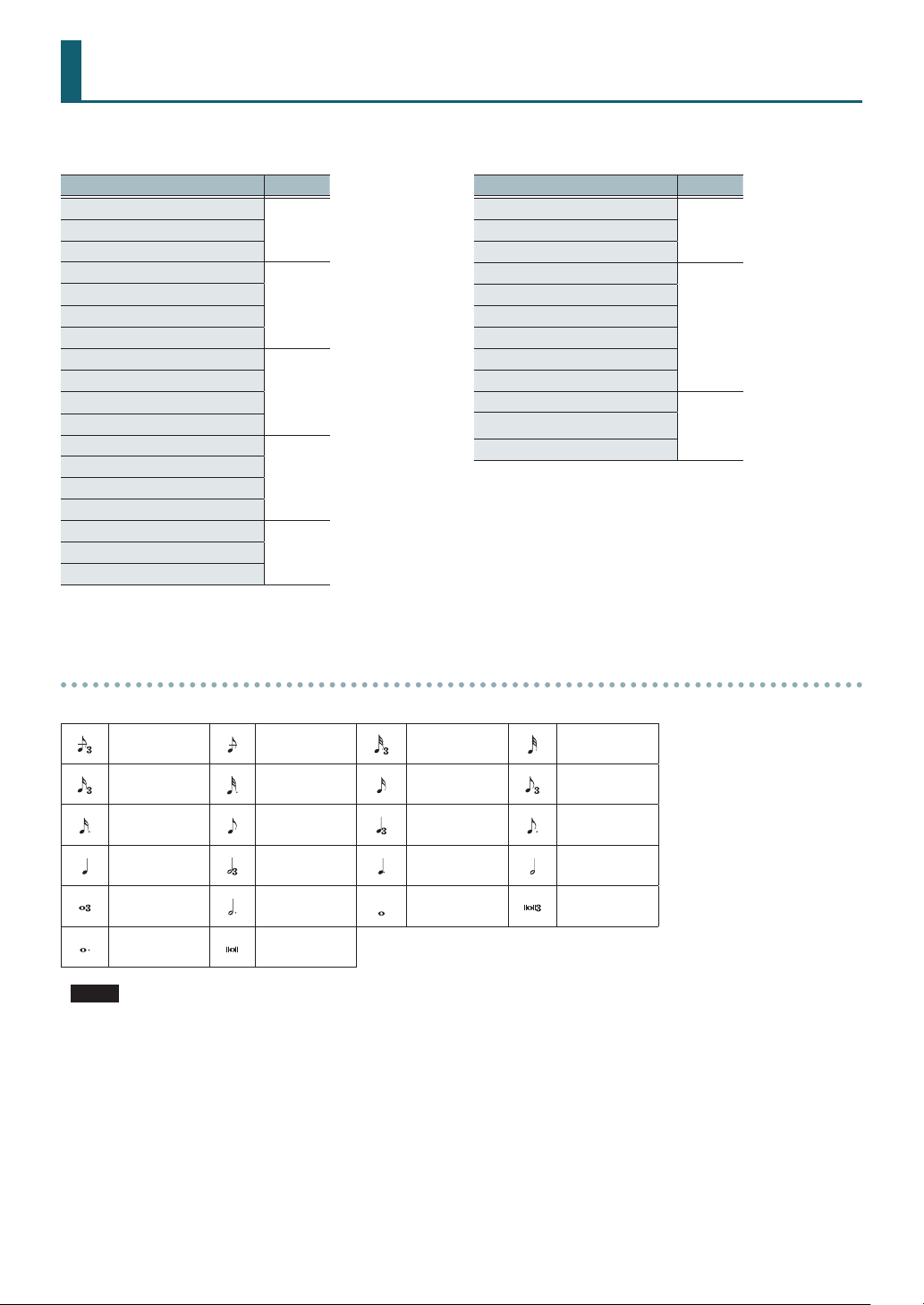
About note values
Eect type Page
AUTO WAH
OD/DS0TW
LOFI COMP
DIST
OVERDRIVE
SATURATOR
T-SCREAM
BIT CRUSH
ISOLATOR
RING MOD
AUTO PAN
p. 8
p. 9
p. 10PITCH SFT
Some eect parameters (such as Rate or Delay Time) can be set by using note values.
Sixty-fourth
note triplet
Sixteenth note
triplet
Dotted
sixteenth note
Quarter note Half-note triplet
Whole note
triplet
Dotted whole
note
Sixty-fourth
note
Dotted thirtysecond note
Eighth note
Dotted half
note
Double note
Thirty-second
note triplet
Sixteenth note
Quarter-note
triplet
Dotted quarter
note
Whole note
Thirty-second
note
Eighth-note
triplet
Dotted eighth
note
Half note
Double-note
triplet
NOTE
If you set the delay time as a note value, slowing down the tempo will not change the delay time beyond a certain length.
There is an upper limit for the delay time so if it is set as a note value and you slow down the tempo until this upper limit is
reached, the delay time cannot change any further. This upper limit is the maximum value that can be specied when setting
the delay time as a numerical value.
2
Multi-Eect Parameters
DELAY
This is a stereo delay.
Parameter Value Explanation
L TmpSync,
R TmpSync
L DlyTime,
R DlyTime
L Phas,
R Phas
FdBkMod
Feedback -98–+98%
HF Dump
Low Gain -15–+15dB Gain of the low frequency range
High Gain -15–+15dB
Level 0–127 Output Level
OFF, ON
1–1300msec,
note
NORMAL,
INVERSE
NORMAL,
CROSS
200–8000
Hz, BYPASS
Species whether the delay
time value of the left/right delay
sounds is specied as a note
value (ON) or not (OFF).
Delay time from the original
sound until the left/right delay
sound is heard
Phase of the left/right delay
sound
NORMAL: Non-inverted
INVERSE: Inverted
Selects the way in which delay
sound is fed back into the eect
NORMAL: The left/right delay
sounds are fed back without
modication.
CROSS: The left/right delay
sounds are alternately
exchanged when fed back.
Adjusts the amount of the delay
sound that’s fed back into the
eect.
(Negative “-” values invert the
phase.)
Adjusts the frequency above
which sound fed back to
the eect is ltered out
(BYPASS: no cut).
Gain of the high frequency
range
TAPE ECHO
A virtual tape echo that produces a realistic tape delay
sound. This simulates the tape echo section of a Roland RE201 Space Echo.
Parameter Value Explanation
Combination of playback heads
to use
Mode
RepeatRate 0–127
Intensity 0–127 Amount of delay repeats
S, M, L, S+M,
S+L, M+L,
S+M+L
Select from three dierent heads
with dierent delay times
S: short
M: middle
L: long
Tape speed
Increasing this value will shorten
the spacing of the delayed
sounds.
Bass -15–+15dB
Treble -15–+15dB
S Pan
M Pan
L Pan
Distortion 0–5
W/F Rate 0–127
W/F Depth 0–127 Depth of wow/utter
Level 0–127 Output level
L64–R63
Boost/cut for the lower range of
the echo sound
Boost/cut for the upper range of
the echo sound
Independent stereo location
for the short, middle, and long
playback heads
Amount of tape-dependent
distortion to be added
This simulates the slight tonal
changes that can be detected
by signal-analysis equipment.
Increasing this value will increase
the distortion.
Speed of wow/utter (complex
variation in pitch caused by tape
wear and rotational irregularity)
REV DLY (REVERSE DELAY)
This is a reverse delay that adds a reversed and delayed
sound to the input sound. A tap delay is connected
immediately after the reverse delay.
Parameter Value Explanation
Threshold 0–127
RevTmpSync OFF, ON
RevDlyTim
RevFeedBk -98–+98%
RevHFDamp
Rev Pan L64–R63
Rev Level 0–127
D1–3 TmpSync OFF, ON
Dly1–3 Tim
1–1300msec,
note
200–8000Hz,
BYPS
1–1300msec,
note
Volume at which the reverse
delay will begin to be applied
Species whether the delay
time value of the reverse delay
is specied as a note value (ON)
or not (OFF).
Delay time from when sound is
input into the reverse delay until
the delay sound is heard
Proportion of the delay sound
that is to be returned to the
input of the reverse delay
(Negative (-) values invert the
phase.)
Frequency at which the
high-frequency content of the
reverse-delayed sound will be
cut (BYPS: no cut).
Stereo location of the reverse
delay sound
Volume of the reverse delay
sound
Species whether the delay
time value of the tap delay is
specied as a note value (ON) or
not (OFF).
Delay time from when sound is
input into the tap delay until the
delay sound is heard
3
Multi-Eect Parameters
Parameter Value Explanation
Proportion of the delay
Dly3FeedBk -98–+98%
D HFDamp
D1 Pan,
D2 Pan
D1 Level,
D2 Level
Low Gain -15–+15dB Gain of the low frequency range
High Gain -15–+15dB
Level 0–127 Output Level
200–8000Hz,
BYPS
L64–R63
0–127 Volume of the tap delay sounds
sound that is to be returned
to the input of the tap delay
(Negative (-) values invert the
phase.)
Frequency at which the high
frequency content of the
tap delay sound will be cut
(BYPS: no cut).
Stereo location of the tap delay
sounds
Gain of the high frequency
range
3TPAN DLY (3TAP PAN DELAY)
Produces three delay sounds; center, left and right.
Parameter Value Explanation
L TmpSync,
R TmpSync,
C TmpSync
L DlyTime,
R DlyTime,
C DlyTime
FeedBack -98–+98%
HF Damp
L Level,
R Level,
C Level
Low Gain -15–+15dB
High Gain -15–+15dB
Level 0–127 Output Level
OFF, ON
1–2600msec,
note
200–8000Hz,
BYPS
0–127 Volume of each delay
Species whether the delay
time value of the left/right/
center delay sound is specied
as a note value (ON) or not
(OFF).
Adjusts the delay time from
the direct sound until the delay
sound is heard.
Adjusts the amount of the
delay sound that’s fed back
into the eect.
(Negative “-” values invert the
phase.)
Adjusts the frequency above
which sound fed back to
the eect is ltered out
(BYPS: no cut).
Gain of the low frequency
range
Gain of the high frequency
range
OD0DELAY (Overdrive0Delay)
Parameter Value Explanation
Overdrive 0–127
4
Degree of distortion
Also changes the volume.
Parameter Value Explanation
Pan L64–R63
TmpSync OFF, ON
DelayTime
FeedBack -98–+98%
HF Dump
Balanc
Level 0–127 Output Level
1–2600msec,
note
200–8000Hz,
BYPS
D100:0W–
D0:100W
Stereo location of the overdrive
sound
Species whether the delay time
value of the delay is specied as
a note value (ON) or not (OFF).
Adjusts the delay time from
the direct sound until the delay
sound is heard.
Adjusts the proportion of the
delay sound that is fed back into
the eect.
(Negative “-” values invert the
phase.)
Adjusts the frequency above
which sound fed back to the
eect will be cut (BYPS: no cut).
Adjusts the volume balance
between the sound that is sent
through the delay (W) and the
sound that is not sent through
the delay (D).
DS0DELAY (Distortion0Delay)
The parameters are essentially the same as in “OD0DELAY”
with the exception of the following one.
Overdrive0Distortion
CHORUS
This is a stereo chorus. A lter is provided so that you can
adjust the timbre of the chorus sound.
Parameter Value Explanation
Type of lter
OFF,
Filter
CutoFrq 200–8000Hz
Pre Delay 0.0–100ms
TmpSync OFF, ON
Rate
Depth 0–127 Depth of modulation
Phase 0–180deg Spatial spread of the sound
LPF,
HPF
0.05–10.00Hz,
note
OFF: no lter is used
LPF: cuts the frequency range
above the Cuto Freq
HPF: cuts the frequency range
below the Cuto Freq
Species the frequency at
which the lter cuts a specic
frequency region
Adjusts the delay time from the
direct sound until the chorus
sound is heard.
Species whether the
modulation rate is specied as a
note value (ON) or not (OFF).
Frequency of modulation
Multi-Eect Parameters
Parameter Value Explanation
Low Gain -15–+15dB Gain of the low range
High Gain -15–+15dB Gain of the high range
Level 0–127 Output Level
SPACE-D
This is a multiple chorus that applies two-phase modulation
in stereo. It gives no impression of modulation, but produces
a transparent chorus eect.
Parameter Value Explanation
Pre Delay 0.0–100ms
TmpSync OFF, ON
Rate
Depth 0–127 Depth of modulation
Phase 0–180deg Spatial spread of the sound
Low Gain -15–+15dB Gain of the low range
High Gain -15–+15dB Gain of the high range
Level 0–127 Output Level
0.05–10.00Hz,
note
Adjusts the delay time from
the direct sound until the
chorus sound is heard.
Species whether the
modulation rate is specied as
a note value (ON) or not (OFF).
Frequency of modulation
OD0CHORS (Overdrive0Chorus)
Parameter Value Explanation
Overdrive 0–127
Pan L64–R63
Pre Delay 0.0–100ms
TmpSync OFF, ON
Rate
Depth 0–127 Depth of modulation
Balanc
Level 0–127 Output Level
0.05–10.00Hz,
note
D100:0W–
D0:100W
Degree of distortion
Also changes the volume.
Stereo location of the overdrive
sound
Adjusts the delay time from the
direct sound until the chorus
sound is heard.
Species whether the
modulation rate is specied as a
note value (ON) or not (OFF).
Frequency of modulation
Adjusts the volume balance
between the sound that is sent
through the chorus (W) and the
sound that is not sent through
the chorus (D).
DS0CHORS (Distortion0Chorus)
The parameters are essentially the same as in
“OD0CHORUS” with the exception of the following one.
Overdrive0Distortion
PHASER A
This is a stereo phaser. A phase-shifted sound is added to
the original sound and modulated.
Parameter Value Explanation
Mode
Manual 0–127
TmpSync OFF, ON
Rate
Depth 0–127 Depth of modulation
Polarity INVR, SYNC
Resonance 0–127 Amount of feedback
CrossFdBk -98–+98%
Low Gain -15–+15dB Gain of the low range
High Gain -15–+15dB Gain of the high range
Level 0–127 Output Level
4-STAGE,
8-STAGE,
12-STAGE
0.05–10.00Hz,
note
Number of stages in the phaser
Adjusts the basic frequency
from which the sound will be
modulated.
Species whether the
modulation rate is specied as
a note value (ON) or not (OFF).
Frequency of modulation
Selects whether the left and
right phase of the modulation
will be the same or the
opposite.
INVR: The left and right phase
will be opposite. When using a
mono source, this spreads the
sound.
SYNC: The left and right phase
will be the same. Select this
when inputting a stereo source.
Adjusts the proportion of the
phaser sound that is fed back
into the eect.
(Negative “-” values invert the
phase.)
PHASER B
This simulates a dierent analog phaser than Phaser A.
Parameter Value Explanation
Speed 0–100 Frequency of modulation
Depth 0–127 Depth of modulation
Low Gain -15–+15dB Gain of the low range
High Gain -15–+15dB Gain of the high range
Level 0–127 Output Level
5
 Loading...