

Page 1

© 2021 Roland Corporation
01
Page 2

Contents
Assembly ...................................... 4
: Checking the Parts ............................. 4
: Assembly ..................................... 4
: Attaching a Strap .............................. 5
: Disassembly................................... 5
: Setting up the Floor Stands . . . . . . . . . . . . . . . . . . . . . 6
: Setting up on a Three-Pillar Stand ............... 6
Panel Descriptions ............................ 8
: Top Panel ..................................... 8
Performance Techniques .......................... 8
: Rear Panel
(Connecting Your Equipment)
............... 9
Getting Ready ................................. 10
: Installing the Batteries ......................... 10
: Turning the Power On/O ...................... 10
: Basic Operations............................... 11
: Setting the Optimum Sound for the Output
Destination
(Output Mode)
........................ 11
Kits ............................................. 12
Memory........................................ 12
Playing......................................... 13
(Kit)
: Selecting a Sound
: Playing Along with a Song ...................... 13
Using the MIX IN Jack ............................. 13
Using a Bluetooth Device .......................... 13
: Using the Lesson Function
Sounding the Ji-uchi
Using the Metronome
Recording
Practicing
(Rec)
.................................. 14
(Practice)
.......................... 13
(Lesson)
............... 13
(Ji-uchi)
........................ 13
(Metronome)
.................... 14
................................ 15
Editing Sounds and Other Settings for Kits
(Kit Edit)
.......................................... 16
: Setting an Instrument
Parameters Specic to Each Instrument............... 17
: Conguring the Eects
Applying an Equalizer for Each Pad
Applying a Compressor to Each Pad
Applying Ambience to the Entire Kit
Applying MFX to Each Pad
: Setting the Kit Level
: Mute Group
(Mute Group)
(Instrument)
(Eects)
(MFX)
(Kit Level)
......................... 20
................ 16
................... 18
(Pad EQ)
............ 18
(Pad Comp)
(Ambience)
.......... 18
......... 19
..................... 19
.................... 20
: Setting How the Nuance Changes According to
Where You Strike the Pad
(Kit Pad Control)
........... 20
: Controlling the Sounds Using a Connected Pedal
(Pedal Control)
: Controlling from an External MIDI Device
Setting the Note Number for Each Pad
Setting the MIDI Channel for Each Pad
Setting the Gate Time for Each Pad
: Naming a Kit
: Giving a Kit a Kanji Name
: Copying a Kit
: Recalling Kits Successively
Selecting a Set List
Creating a Set List
.................................... 21
(Kit MIDI)
(Note Number)
(Channel)
(Gate Time)
(Kit Name)
(Kit Copy)
.......................... 22
(Kit Kanji Name)
.......................... 23
(Set List)
............... 23
(from Selecting Banks to Selecting Kits)
(from Creating a List to Saving to a Bank)
..... 21
......... 22
........... 22
........... 22
...... 23
..... 24
Importing and Playing Audio Files
(User Sample)
: Importing an Audio File
: Previewing User Samples
: Editing a User Sample
: Renaming a User Sample
: Deleting a User Sample
: Renumbering User Samples to Eliminate Blanks
(Renumber)
: Optimizing the User Sample Area
: Deleting All User Samples
..................................... 25
(Import)
.................. 25
(Preview)
(Edit)
(Rename)
(Delete)
................ 25
...................... 26
................ 26
.................. 26
...................................... 27
(Delete All)
(Optimize)
. . . . . . . . . . . . . . 27
....... 27
. 21
2
Page 3

Contents
Conguring the Trigger Settings ............. 28
: Setting the Sensitivity and Other Parameters for
Each Pad
Checking the Velocity and Other Settings of the Pads
You Strike
: Conguring the Other Pad Not to Sound
(Xtalk Cancel)
: Specifying the Pads to Use
: Preventing the Currently Edited Pad from
Changing
(Pad Settings)
............................ 28
...................................... 29
..................................... 29
(Trigger Lock)
(Active Pad)
........................... 30
............. 29
Using the Bluetooth® Functionality .......... 31
: Using the TAIKO-1 to Hear Music Played from a
Mobile Device ................................. 31
Registering a Mobile Device
Conguring the Bluetooth Function
Connecting an Already-Paired Mobile Device .......... 32
Playing Music from a Mobile Device.................. 32
Checking the Bluetooth Status
: Resetting the Bluetooth Pairing Settings
Backing up to USB Flash Drive
(Pairing)
.................. 31
(Setup)
............ 31
(Bluetooth Status)
.......... 32
(USB Memory)
(Reset)
... 32
... 33
Troubleshooting .............................. 41
Appendix ...................................... 42
: Adjusting the Head Tension..................... 42
: Kit List ........................................ 43
: Instrument List ................................ 43
: MFX List ...................................... 45
: Ji-uchi List..................................... 52
: Ji-uchi Instrument List.......................... 52
: Metronome Sounds ............................ 53
: Allowable Characters........................... 53
: Allowable Kanji Characters ..................... 53
Main Specications ........................... 54
MIDI-Related Settings......................... 55
: Note Numbers for Each Pad
(Defaults)
: MIDI Output Specications ..................... 55
: High-Resolution Velocity Prex
: Program Change Messages ..................... 55
............. 55
(Controller Number 88)
55
: Backing up the Settings
: Loading Backup Data
: Deleting Backup Files
(Save Backup)
(Load Backup)
(Delete Backup)
: Initialized a USB Flash Drive
(USB Memory Format)
.............. 33
................ 34
.............. 35
Making Overall Settings for the TAIKO-1
(Others)
.......................................... 36
: Conguring the OUTPUT/PHONES Jack
(Output Settings)
.................................. 36
: Conguring the Pedal Jacks and Shortcut
Settings
(Control Settings)
: MIDI-Related Settings
: Conguring the Master Equalizer
: Conguring the Master Compressor
.......................... 36
(Global MIDI)
................ 38
(Master EQ)
(Master Comp)
: Setting the Screen and AUTO OFF Function
(LCD/Auto O)
.................................... 39
: Viewing Information for This Instrument
(Version Info)
: Returning to the Factory Settings
..................................... 39
(Factory Reset)
....... 38
TAIKO-1 Audio Signal Flow ................... 56
.... 35
.. 39
.... 40
3
Page 4

Assembly
Checking the Parts
1 2
5
8 9 10
Part name Quantity
Rods (with pad attachment screws) 8
1
Pads 2
2
Sound module 1
3
Rubber ring (for securing the sound module) 4
4
Trigger cables (0.2 m) 2
5
Trigger cables (1.0 m) (*1) 2
6
AC adaptor + power cord 1
7
Drum key 1
8
Hex wrench (*2) 1
9
Cable clamps 3
10
6
r
Assembly
3
4
7
If necessary, spread out a blanket or similar material to prevent the
TAIKO-1 or oor from being scratched during assembly.
1. Attach the rods to the pad
1
1-1. Place the pad (
1-2. One at a time, insert the rods (
pad.
MEMO
The rods should be facing diagonally when correctly inserted.
1-3. Use the drum key
until they no longer turn.
The appropriate tightness is approximately when the bolt head is no
longer visible.
) so that the surface with holes in it faces upward.
2
to tighten the bolts of the rods (1 eight locations)
8
eight locations) into the holes of the
1
1
r
2
*1 Use the trigger cable (1.0 m) when playing the taiko while not on your shoulder.
&
“Setting up the Floor Stands” (p. 6)
*2 The hex wrench is used to adjust the tension of the heads.
&
“Adjusting the Head Tension” (p. 42)
Watch a video that explains TAIKO-1 assembly.
Access the following URL on your
computer or smartphone.
http://roland.cm/taiko_qs
Protrusions on
the pad
2
1-4. Place the other pad (
upward.
1-5. Turn over the pad to which the rods are attached, position the pads so
that the projections of the two pads are aligned, and then consecutively
insert the rods into the holes of the other pad one by one.
1-6. While making sure that the rods are inserted in the holes of the pad, use
the drum key
they no longer turn.
) so that the surface with holes in it is facing
2
to tighten the bolts of the rods (1 eight locations) until
8
4
Page 5

Assembly
2. Attaching the sound module
* When attaching the sound module, take care that you are not injured by
an rubber ring.
2-1. Attach an rubber ring (
module (
Gently pull the rubber ring to t it into the groove.
2. Pull gently
2-2. Loop the rubber ring over the hooks of the rods that are located opposite
the protrusions on the pads (four locations).
Protrusions on the pad
) (four locations).
3
Rubber ring
1. Fit into this groove
) to each of the four corners of the sound
4
Protrusions on the pad
(opposite side)
Mounting order
Attaching a Strap
You can attach a commercially available taiko strap and play this
instrument.
To attach a strap, wrap it around the tip of the rod as shown in the
illustration (two locations).
Wrap in a gure-eight, and then tie.
2
1
1
Attach the strap to these two locations.
NOTE
If the wrapping is insucient, the strap might be displaced or
disconnected. Fasten it securely to prevent the instrument from
dropping.
Disassembly
Hooks
Sound module
Hooks
3. Attaching the trigger cables
Mounting order
Rubber ring
4
1. Detach the sound module
1-1. Disconnect all connection cables such as the AC
adaptor and trigger cables.
1-2. One by one, pull and detach each rubber ring
that is attached to the rod hooks (four locations),
and detach the sound module.
This is easier if you remove the rubber rings rst.
2. Loosen all bolts for the rods of the pad 1
2-1. Use the drum key to loosen the
bolts until you can see their
heads from the side.
Do not remove them from the
rods; leave them attached.
Loosen all eight bolts of the
rods.
3. Pull the rods out of the pad
3-1. Taking care not to apply excessive force
to the connector section, pull out the rod
perpendicularly from the pad.
Gap
3-1. Connect the trigger cables (0.2 m) (
pads.
3-2. Connect the other end of each cable to the TRIG IN 1/2 jacks of the sound
module.
) to the TRIG OUT jacks of the two
5
4. Disassemble the pad 2 in the same way
4-1. Loosen the bolts of the other pad in the same way, and pull out the rods.
5
Page 6

Assembly
Setting up the Floor Stands
What you’ll need besides the TAIKO-1 and stand
5 String (0.5 m) × 4
5 Thick cloth/fabric (used for cushioning) × 3
1. Remove the pads and sound module of the TAIKO-1.
&
“Disassembly” (p. 5)
6. Turn the assembled unit over.
7. Connect the pad and sound module with the included
trigger cable (1.0 m).
Pad: TRIG OUT jack
TAIKO-1: TRIG IN 1 jack (or TRIG IN 2 jack)
Set all Xtalk Cancel parameters to “0.”
&
“Conguring the Other Pad Not to Sound (Xtalk Cancel)”
(p. 29)
Depending on the stand and how you strike the TAIKO-1, you may
get a better drumming feel by adjusting the parameters.
&
“Conguring the Trigger Settings” (p. 28)
MEMO
You can line up two sets of
pads that you have respectively
attached to the oor stands, for
two people to play. In this case,
connect the TRIG OUT jack of the
second pad to the TRIG IN 2 jack (or
the TRIG IN 1 jack) of the TAIKO-1.
Place the sound module on the
oor for use.
Disassembly
To disassemble the units, use the reverse process you used when
assembling them.
* The rods and rings are not used here.
2. Wrap the cloths or fabric around the stand (three
places).
3. Turn the pad over and thread the strings through
the holes where the rods are usually mounted (four
places).
* Make sure to thread the string
through the holes at the
specied places. If you thread
the strings through other places,
this could damage the sensor.
4. Flip the stand upside down that you wrapped with
cloths or fabric in step 1, and place it on the pad that
you turned over.
Position the pad so that the protrusion faces towards you.
5. Tie the strings into knots (four places).
Where to knot the
strings (four places)
Setting up on a Three-Pillar Stand
What you’ll need besides the TAIKO-1 and stand
5 String (1 m) × 3
1. Disconnect all connection cables such as the AC
adaptor and trigger cables.
2. Remove the sound module of the TAIKO-1.
Leave the rubber rings on the sound module.
Protrusions on the pad
6
Page 7

3. Thread the string through the belt on each pillar of
the three-pillar stand, and tie a string into a loop
(three places).
4. Hook the string loops onto the rods of the TAIKO-1, as
shown in the illustration.
Assembly
Caution when replacing the head
(do not insert your hand or ngers)
Do not insert your hand or ngers into the area indicated by the
arrow in the illustration. Doing so might cause injury or damage.
Frame
Head
Gap
Gap
The rubber components of the head and rim are consumable
parts whose performance will decline with use over time.
If the head becomes torn, or if the surface of the head sags even
when the head tension is correctly adjusted, replace the head.
If the rubber of the rim is damaged, contact the retailer from
whom you purchased the product, or the nearest Roland Service
Center.
&
“Adjusting the Head Tension” (p. 42)
Place the pad so the protrusions on the pad face towards you.
Each string loop should hook onto two rods.
5. Attach the sound module.
Attach the sound module so that it is a little to the right from the
center, making the buttons easier to operate.
View from the front (player’s side)
Handling caution
Do not touch the screws of the
projections, since doing so might
cause the heads to loosen.
Specifying the pads to use
With the TAIKO-1, you can use both pads; but if you want to use
only one pad, you can enable just one. This helps prevent the
lower surface from operating unintentionally.
&
“Specifying the Pads to Use (Active Pad)” (p. 29)
(about the screws)
(Active Pad)
Connect the pad and sound module with the included trigger
cable (0.2 m).
Pad: TRIG OUT jack
TAIKO-1: TRIG IN 1 jack
(Do not connect the sound module to the lower pad.)
Disassembly
To disassemble the units, use the reverse process you used when
assembling them.
7
Page 8

Panel Descriptions
Head Rim
1
2
1
Top
1
Pad 1 (head 1/rim 1)
Pad 1 (PAD1) is the pad that is attached to
the upper surface and connected to the TRIG IN 1 jack.
The mesh area is called the “head (PAD1H),” and the rubber area is
called the “rim (PAD1R).”
2
Pad 2 (head 2/rim 2)
Pad 2 (PAD2) is the pad that is attached to the lower surface and
connected to the TRIG IN 2 jack.
The mesh area is called the “head (PAD2H),” and the rubber area is
called the “rim (PAD2R).”
Bottom
2
Performance Techniques
About the “bachi” (sticks) to use
You can use bachi (sticks) made of either magnolia tree
wood or maple.
Using maple sticks
When using maple sticks, the mesh head (surface) and the
rubber on the rim (edge) wears out more quickly.
Wear and tear on the sticks
The sticks may tend out wear out after playing on the mesh (heads) for some time.
Caution on using chipped/broken sticks
Do not use chipped or broken sticks, as doing so may damage the surface of the heads.
* When playing the TAIKO-1, do not strike any location other than the surface or rim of the pad (including
the rods or the sound module). Failure to observe this causes malfunctions or damage to the instrument.
Head
Strike the head.
The nuances of the tone change
according to the location of the head
that you strike.
NOTE
If you strongly strike the mesh area between the surface and
the rim (the gray area in the illustration), the “bachi” (sticks)
will strike the material on the rear of the head, and the sensor
will not work correctly. Since this will also damage the parts,
take care not to perform so strongly that you strike the
material on the rear.
MEMO
5 This instrument does not support playing the head and rim of the same pad
simultaneously (including open rim shots).
5 This instrument does not support playing the rim of pad 1 and of pad 2
simultaneously.
* Depending on how the pads are set up, it is possible to simultaneously strike the rim of pad
1 and of pad 2.
&
“Setting up the Floor Stands” (p. 6)
Rim
Do not strike the projection
of the rim.
Doing so will damage the
“bachi” (sticks) and will also
cause malfunctions and
faulty operation.
Strike the rim.
You hear a sound other than that
produced by the head.
Top
Bottom
Top Panel
1
3
2
4
5
1
Display
Shows various information according to the operation.
2
[H] [I] buttons
Move the cursor. The currently selected item is highlighted.
3
F1 (left) button, F2 (right) button
The function of these buttons changes depending on what is
shown in the display.
4
] (TOMOE) button
[
Regardless of the screen that is shown, pressing this button takes
you back to the top screen and selects a favorite kit (with the
factory settings).
You can change the function of this button.
&
“Conguring the Pedal Jacks and Shortcut Settings (Control
Settings)” (p. 36)
5
[+] [-] buttons
Selects a kit or modies a value.
6
[L] button
Turns the power on/o.
7
[ ] [ ] buttons
Raises or lowers the volume. When you press a button, the current
volume is shown (the previous screen reappears after several
seconds).
6
7
8
Page 9

Panel Descriptions
Rear Panel
* To prevent malfunction and equipment failure, always turn down the volume, and turn o all the units before making any connections.
E
TRIG IN 2 jack
A
OUTPUT jack
(Connecting Your Equipment)
F
DC IN jack
Connect the included AC adaptor to
this jack.
’
to AC outlet
Pad 2 Pad 1
AC adaptor
Cord hook
G
Batteries
&
“Installing the Batteries” (p. 10)
J
USB COMPUTER port
K
USB MEMORY port
D
TRIG IN 1 jack
B
FOOT SW jack
A
OUTPUT jack (mono)
Outputs the sound. Connect this to your
amplied speaker or mixer.
As necessary, use the cable clamp to tie the cable
to the rod.
B
FOOT SW jack
You can connect a footswitch (BOSS FS-5U, FS6; sold separately) and use it to control various parameters.
&
“Conguring the Pedal Jacks and Shortcut Settings (Control
Settings)” (p. 36)
Factory settings:
You can use FOOT SW 1/2 to step forward or backward through the kits, one
at a time.
C
EXP PEDAL 1/2 jacks
You can connect an expression pedal (EV-5, sold separately) and
use it to control various parameters.
&
“Conguring the Pedal Jacks and Shortcut Settings (Control
Settings)” (p. 36)
Factory settings:
You can use EXP PEDAL 1 to control the overall volume.
You can use EXP PEDAL 2 to control the volume of the “ji-uchi” (base beat).
* Use only the specied expression pedal. Connecting any other expression
pedals may cause the unit to malfunction or become damaged.
D
TRIG IN 1 jack
Use the included trigger cable to connect the TRIG OUT jack of pad
1 to the TRIG IN 1 jack.
E
TRIG IN 2 jack
Use the included trigger cable to connect the TRIG OUT jack of pad
2 to the TRIG IN 2 jack.
C
EXP PEDAL 1/2 jacks
Cable clamps
H
PHONES jack
F
DC IN jack
Connect the included AC adaptor to this jack.
* Use the cord hook to secure the cord of the AC adaptor as shown in the
illustration.
G
Batteries
&
“Installing the Batteries” (p. 10)
H
PHONES jack
Connect your headphones here. Use a stereo mini plug for this
connection.
* Even if headphones are connected, sound is still output from the OUTPUT
jack.
I
MIX IN jack
Connect an external audio device.
Use a stereo mini plug for this connection.
J
USB COMPUTER port
Connect your computer to the TAIKO-1’s USB port via USB cable.
* Do not use a micro USB cable that is designed only for charging a device.
Cables used for charging only cannot transmit data.
K
USB MEMORY port
You can connect a USB ash drive here.
&
“Backing up to USB Flash Drive (USB Memory)” (p. 33)
* Never turn o the power or remove the USB ash drive while the message
“Processing...” is displayed.
I
MIX IN jack
Connect an audio device
here.
9
Page 10

Getting Ready
Installing the Batteries
As an alternative to using the AC adaptor, you can use commercially
available AA-size rechargeable Ni-MH batteries.
* When an AC adaptor is used, the unit is powered by the AC adaptor even
if batteries are installed.
* When turning the unit over, be careful so as to protect the buttons from
damage. Also, handle the unit carefully; do not drop it.
1. Remove the battery cover.
1-1. Remove the thumbscrew from the battery cover.
1-2. Slide the battery cover forward and remove it.
Battery cover
Thumbscrew
2. Insert the batteries into the battery case in the
correct orientation.
3. Close the battery cover.
* Handling batteries improperly may cause the risk of explosion or uid
leakage. Make sure to carefully observe all of the items related to
batteries that are listed in “USING THE UNIT SAFELY” and “IMPORTANT
NOTES” (found in the leaet “USING THE UNIT SAFELY” and the Owner’s
Manual).
Remaining battery indication
When the remaining battery power runs low, a battery low icon
( ) appears in the upper right of the display. When this appears,
install fresh batteries as soon as possible.
If you continue to use the instrument in this state, the “Battery Low!”
message appears, and nally the TAIKO-1 stops functioning entirely.
Turning the Power On/O
* Before turning the unit on/o, always be sure to turn down the volume
on all connected devices. Even with the volume turned down, you might
hear some sound when switching the instrument on/o. This is normal
and does not indicate a malfunction.
Turning the power on
[L] button
[ ] [ ] buttons
1. Turn on the equipment in this order: TAIKO-1 (press
the [L] button) 0 connected devices.
2. Use the [ ] [ ] buttons to adjust the volume.
MEMO
Hold down the [ ] button and press the [ ] button to make the
value increase quickly. Hold down the [ ] button and press the
[ ] button to make the value decrease quickly.
* The power to this instrument turns o automatically after a certain
amount of time has passed since it was played or operated (Auto O
function).
If you do not want the power to turn o automatically, disengage
the Auto O function.
&
“Setting the Screen and AUTO OFF Function (LCD/Auto O )”
(p. 39)
5 To restore power, turn the power on again.
Turning the power o
1. Turn o the equipment in this order: connected
devices 0 TAIKO-1 (long-press the [L] button).
10
Page 11

Getting Ready
Basic Operations
Function settings
These buttons execute the functions shown in the lower part of the
display.
The functions vary for each screen.
* In the Owner’s Manual, these buttons are described as “function” and
(button): for example, “MENU” (F2 button).
Moving the cursor
(F1/F2 buttons)
F2 buttonF1 button
([H] [I] buttons)
Changing a value ([+] [–] buttons)
[+] [-] buttons
Use the [+] [–] buttons to change the value that is highlighted by the
cursor.
MEMO
If you hold down the [+] button and press the [–] button, the value
increases quickly. If you hold down the [–] button and press the [+]
button, the value decreases quickly.
TOMOE boost
(speed up)
[H] [I] buttons
The cursor is a highlighted area onscreen that shows the setting you
can change. If there are multiple items to set onscreen, use the [H] [I]
buttons to move the cursor to the item you want to change.
MEMO
Press the [I] button while holding down the [H] button to make the
cursor move up quickly, and press the [H] button while holding down
the [I] button to make the cursor move down quickly.
Editing a value
If you hold down the [ ] (TOMOE) button and press the [+] or
[–] button, the value changes at ultra-high speed.
Moving the cursor
If you hold down the [ ] (TOMOE) button and press the [H] or
[I] buttons, the value changes at ultra-high speed.
Changing the volume
If you hold down the [ ] (TOMOE) button and press the [ ]
or [ ] button, the volume changes at ultra-high speed.
Setting the Optimum Sound for the Output
Destination
&
“Conguring the OUTPUT/PHONES Jack (Output Settings)”
(p. 36)
(Output Mode)
11
Page 12
Kits
Layer ALayer A
Layer BLayer B
Layer ALayer A
Layer BLayer B
Layer ALayer A
Layer BLayer B
Layer ALayer A
Layer BLayer B
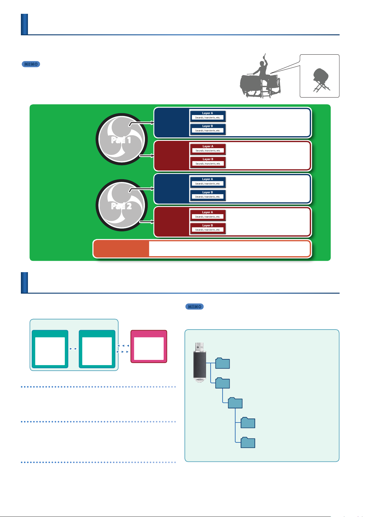
The sounds that play when you strike the pads of this instrument are called “instruments.” The set
of instruments allocated to each pad is called a “kit.” The kits are congured as shown below.
MEMO
When you change the settings for a kit, the changes are saved automatically.
Kit
Kits 1–100
Surface/head
(PAD1H)
Pad 1
Edge/rim
(PAD1R)
Surface/head
(PAD2H)
Pad 2
Edge/rim
(PAD2R)
Kit
Volume, pan, pad compressor, pad equalizer, how
each layer is sounded, etc.
Volume, pan, pad compressor, pad equalizer, how
each layer is sounded, etc.
Volume, pan, pad compressor, pad equalizer, how
each layer is sounded, etc.
Volume, pan, pad compressor, pad equalizer, how
each layer is sounded, etc.
Instrument
Overall kit settings
Eect, kit name, MIDI settings, etc.
Memory
The settings for kits, triggers and so on are saved in what is called
“memory.”
TAIKO-1
LOAD
SAVE
USB memory
Backups
Kits
User samples
COPY
User memory
Kits
Set list
Trigger settings
System settings
User samples
Ji-uchi settings
Preset memory
Kits
Trigger settings
Set list
System settings
Ji-uchi settings
Preset memory
This is where the factory default settings are stored.
You can copy the preset memory data to user memory and restore the
unit to factory settings.
User memory
The settings used when editing or playing this instrument are stored
here.
You can load or copy data from a USB ash drive or from preset
memory (p. 33).
MEMO
5 Data saved to USB ash drive can be loaded or copied into user memory. For
details, refer to “Loading Backup Data (Load Backup)” (p. 34).
USB ash drive folder architecture
IMPORT folder
If there are audio les that you want to import as user samples, save them in this
folder.
Roland folder
The TAIKO-1’s backup data is saved here.
TAIKO-1 folder
Backup folder
Backup data is saved here.
Kit folder
Kit backup data is saved here.
USB ash drive (32 GB max.)
The settings saved in user memory are stored as a single set on the
USB ash drive, and up to 99 sets can be saved (backed up).
You can also save up to 999 kits aside from the backups.
12
Page 13

Playing
Selecting a Sound
The TAIKO-1 assigns separate sounds to the head and rim of the two
pads. These four sounds are collectively called a “k it .”
There are 50 preset kits. By switching kits, you can perform using a
variety of dierent sounds.
(Kit)
1. Press “BACK” (F1 button) several times to access the top
screen.
2. Use the [+] [–] buttons to select the kit.
About the top screen
This is the basic screen of the TAIKO-1, which appears when you turn
on the power.
Kit number
Kit name
If a Japanese (kanji) name is specied for
the kit, the kanji name is also shown.
MEMO
You can edit the sounds of the kit.
For details, refer to “Editing Sounds and Other Settings for Kits (Kit
Edit)” (p. 16).
Trigger indicator
The strength at which you strike the head or rim is shown in six levels.
Function
Displays if functions are assigned to
the F1 and F2 buttons.
Using the Lesson Function
You can sound a “ji-uchi” (base beat) or metronome, and practice along
with this to improve your rhythmic accuracy, or record and play back
your performance.
(Lesson)
Sounding the Ji-uchi (Ji-uchi)
The TAIKO-1 can sound a ji-uchi, which is like a metronome. By
performing along with the ji-uchi, you can practice the basics and
improve your performance skill.
What is ji-uchi?
Ji-uchi is the basic rhythm of the song.
The ji-uchi is struck like a metronome, and the song is played in
time with it.
Since the ji-uchi also plays a role in determining the expression
or tempo of the song (corresponding to the conductor of an
orchestra), it is an extremely important part.
1. Press “MENU” (F2 button).
2. Use the [
press “SELECT” (F2 button).
3. Use the [
press “SELECT” (F2 button).
The setting screen appears.
H
] [I] buttons to select “Lesson,” and then
H
] [I] buttons to select “Ji-uchi,” and then
Playing Along with a Song
Using the MIX IN Jack
You can perform along with a song that’s playing back on the external
device, if the output from that device is input via the MIX IN jack.
* To adjust the playback volume, adjust the volume on your mobile device.
Using a Bluetooth Device
If an external device is connected via Bluetooth, you can play along
with a song playing back on the external device.
&
“Using the Bluetooth® Functionality” (p. 31)
Parameter
[H] [I] buttons
Ji-uchi Volume 0–31, MAX Sets the volume of the ji-uchi.
Track
Tempo 20–260 Sets the tempo.
Velocity 1–32 Sets the strength of the sound.
* The tempo and velocity can be set for each track.
Value
[+] [-] buttons
&
“Ji-uchi List”
(p. 52)
Explanation
Selects the ji-uchi pattern.
4. Press “PLAY p” (F2 button).
You can also switch to another screen while the ji-uchi plays.
5. Press “STOP q” (F2 button).
If a screen other than the ji-uchi setting screen is shown, access the
ji-uchi setting screen and then press “STOP q” (F2 button).
6. Press “BACK” (F1 button) several times to return to the
top screen.
MEMO
You can use MIDI to make the instrument play that sounds the jiuchi. For details, refer to “Ji-uchi Instrument List” (p. 52).
13
Page 14

Playing
Using the Metronome
(Metronome)
1. Press “MENU” (F2 button).
2. Use the [
press “SELECT” (F2 button).
3. Use the [
then press “SELECT” (F2 button).
The setting screen appears.
Parameter
[H] [I] buttons
Tempo 20–260
Beat 1–9
Rhythm Type
Sound
Pan L30–CTR–R30
Metronome Volume 0–31, MAX
H
] [I] buttons to select “Lesson,” and then
H
] [I] buttons to select “Metronome,” and
Value
[+] [-] buttons
ˇ–˜
&
“Metronome
Sounds” (p. 53)
Explanation
Sets the tempo of the
metronome.
Sets the time signature (the
number of beats per measure).
Sets the interval of the
metronome.
Adjusts the metronome’s sound.
Sets the stereo position of the
metronome.
Sets the volume of the
metronome.
4. Press “START p” (F2 button).
5. Press “STOP q” (F2 button).
6. Press the F1 button several times to return to the top
screen.
Recording
Here’s how to record your performance and play it back repeatedly.
(Rec)
1. Press “MENU” (F2 button).
2. Use the [
press “SELECT” (F2 button).
3. Use the [
“SELECT” (F2 button).
The STANDBY screen appears.
H
] [I] buttons to select “Lesson,” and then
H
] [I] buttons to select “Rec,” and then press
4. Press “START” (F2 button) to start recording.
The screen switches to “RECORDING...,” and recording starts.
5. Press “STOP” (F1 button) to stop recording.
The PLAYBACK screen appears.
LOOP: Turn this on if
you want to play back
repeatedly. Turn this o
if you want to play back
only once.
6. Press “PLAY p” (F2 button) to play back.
To stop, press “STOP ” (F2 button).
7. When you are nished, press “BACK” (F1 button).
A conrmation message appears.
If you decide to cancel, press “CANCEL” (F1 button).
NOTE
When you exit the REC (PLAYBACK) screen, the recorded content is
lost.
8. Press the [+] button to exit the PLAYBACK screen.
The STANDBY screen appears.
9. Press the F1 button several times to return to the top
screen.
14
Page 15

Playing
Practicing
(Practice)
This lets you practice keeping the tempo with your body.
For the rst few measures, the click plays at the specied volume, but
for the next several measures the click is muted. This cycle of several
measures continues until you stop it.
1. Press “MENU” (F2 button).
2. Use the [
press “SELECT” (F2 button).
3. Use the [
press “SELECT”
The setting screen appears.
Parameter
[H] [I] buttons
Measures 2, 4, 8, 16
Quiet
Metronome Volume 0–31, MAX
H
] [I] buttons to select “Lesson,” and then
H
] [I] buttons to select “Practice,” and then
(F2 button).
Value
[+] [-] buttons
RANDOM
1, 2, 4
Explanation
Specify the length (measures) of
the interval for which the click
alternates between “sounding”
and “quiet.”
The length of the “Quiet” interval
randomly changes each time.
Species the length (number of
measures) of the “Quiet” interval.
This setting cannot be longer
than half of the “Measures” value.
Sets the volume of the
metronome.
4. Press “START” (F2 button) to start practice.
5. Strike the pad in time with the metronome.
The metronome plays during the rst several measures. When you
reach the last measure during which the metronome plays, the
screen indicates “Ready..”
When the metronome stops sounding, the screen indication
changes to “Quiet.” Continue striking the pads during this time.
After the Quiet region, the proportion of your strikes that were
played at an accurate tempo are shown as a percentage value.
6. Press “STOP” (F1 button) to nish practicing.
7. Press the F1 button several times to return to the top
screen.
15
Page 16

Layer ALayer A
Layer BLayer B
Layer ALayer A
Layer BLayer B
Editing Sounds and Other Settings for Kits
(Kit Edit)
Kits and instruments
On the TAIKO-1, the sounds that play when you strike the pads
are called “instruments” (INST). The set of instruments allocated
to each pad is called a “ k it.”
Surface/head
Pad
Edge/rim
Selecting a pad to congure
To edit the settings for a pad, strike that pad to select it.
rim of a pad, strike the rim.
Preventing the currently edited pad from changing
(Trigger Lock)
If you want to audition your performance sounds while you edit
the instruments, you can specify that the currently edited pad
does not change even if you strike another pad.
&
“Preventing the Currently Edited Pad from Changing (Trigger
Lock)” (p. 30)
* The pad remains locked even if you use MIDI messages to switch
pads.
MEMO
By assigning “Trig Lock” to the assignable buttons (p. 30),
you can use buttons such as [ ] (TOMOE) to switch this on/
o.
To select the
Saving your settings
Since the TAIKO-1 automatically saves the values that you
change, there’s no need to perform a specic operation to save
your settings.
Settings are also saved when you turn o the power.
Setting an Instrument
(Instrument)
This shows how to assign dierent sounds to the head or rim.
You can assign two sounds to an “instrument,” which can also be
played as a layer (layers A/B).
1. On the KIT EDIT screen, select “Instrument” and press
“SELECT” (F2 button).
The INSTRUMENT screen appears.
Layer A
Layer B
Set the “SW” (switch) to “ON ” to display the category and name, and to select the sound.
Category
Pad name
Sound Name
Layer B ON/OFF
2. Strike to select the pad that you want to set.
3. Press “EDIT” (F2 button) for more detailed settings.
The INST EDIT (LAYER A) screen appears.
This shows how to edit the sounds of a kit.
1. Press “MENU” (F2 button).
2. Use the [
press “SELECT” (F2 button).
The KIT EDIT screen appears.
3. Use the [
press “SELECT” (F2 button).
Setting an Instrument (Instrument) page 16
Conguring the Eects (Eects) page 18
Setting the Kit Level (Kit Level) page 20
Mute Group (Mute Group) page 20
Setting How the Nuance Changes According to Where You Strike the Pad (Kit Pad Control)
Controlling the Sounds Using a Connected Pedal (Pedal Control) page 21
Controlling from an External MIDI Device (Kit MIDI) page 21
Naming a Kit (Kit Name) page 22
Giving a Kit a Kanji Name (Kit Kanji Name) page 22
H
] [I] buttons to select “Kit Edit,” and then
H
] [I] buttons to select the item, and then
page 20
Here we make the settings for layer A.
4. Use the [
H
] [I] buttons to select the item, and then
use the [+] [-] buttons to change the setting.
Parameter
[H] [I] buttons
Pad PAD1H–PAD2R Selects the pad to set.
Level
“Parameters
Specic to Each
Instrument”
Pitch -2400–2400
Decay 1–100 Sets the length of the sound’s decay.
Dynamic Enhnc
Sw
Transient Sw OFF, ON
Transient Time 1–10
Transient Attack -100–+100
Value
[+] [-] buttons
-INF, -60.0–+6.0
(in units of 0.5)
[dB]
&
“Parameters Specic to Each Instrument” (p. 17)
OFF, ON
Explanation
Sets the volume of the instrument.
Sets the pitch of the instrument (in units of
one cent).
* Semitone = 100 cents
Sets whether to use emphasize when you
play the instrument strongly (ON) or not
(OFF).
* This cannot be specied for user samples.
Turn this on to boost or suppress the attack
or release portions of the instrument (the
transients).
* This cannot be specied for user samples.
Adjusts the time over which the attack
changes.
Adjusts the attack.
Use this to emphasize or de-emphasize the
attack portion of the sound.
16
Page 17

Editing Sounds and Other Settings for Kits (Kit Edit)
Parameter
[H] [I] buttons
Transient Release -100–+100
Transient Gain -12–+6 [dB]
Value
[+] [-] buttons
Explanation
Adjusts the release.
Use this to emphasize or de-emphasize the
release portion of the sound.
Adjusts the volume after transient
adjustment,
5. Press “LAYER B” (F2 button).
The INST EDIT (LAYER B) screen appears.
Now we make the settings for layer B.
6. Use the [
H
] [I] buttons to select the item, and then
use the [+] [-] buttons to change the setting.
* The parameters are the same as for layer A.
7. Press “COMMON” (F2 button).
The INST EDIT (COMMON) screen appears.
Here we congure the instrument overall (the settings common to
layer A/B).
8. Use the [
use the [+] [-] buttons to change the setting.
Parameter
[H] [I] buttons
Pad PAD1H–PAD2R Selects the pad to set.
Layer Type
Fade Point
Pan L30–R30 Adjusts the stereo position of each pad.
Fixed Value
H
] [I] buttons to select the item, and then
Value
[+] [-] buttons
These parameters set how layer A/B sound.
MIX
FADE1
FADE2, FADE3
SWITCH
1–127, 127+1–
127+32
1–127, 127+1 –
127+32, OFF
Explanation
Layers A and B are always played together
as a layer.
When you strike the pad at the “Fade Point”
level or harder, layer B also plays together
as a layer.
When you strike the pad at the “Fade Point”
level or harder, the sound of layer B is
added in as a layer, according to how hard
you play.
FADE2: The volume of layers A and B are
the same when the Fade Point is 127 or
greater.
FADE3: The volume of layers A and B are
the same when the Fade Point is 127 + 32.
Switches between layers according to how
hard you play. Layer A plays when you strike
the pad at a level weaker than the “Fade
Point;” and layer B plays when you strike the
pad at a level stronger than the “Fade Point.”
If you set the strength at which layer B plays
to “1,” layer B always plays regardless of how
hard you strike the pad.
If you set this to “127 + 32” (or “127” when
“HI-Reso Velocity” is “OFF”), layer B only
sounds when you strike the pad the
hardest.
* This is not available when the Layer Type is
“MIX.”
This produces a sound at a xed velocity,
regardless of how hard you strike the pad.
This is useful when playing the phrases
assigned to the user samples at a xed
volume.
Parameter
[H] [I] buttons
Min Volume 0–15
Max Volume -5–0
Value
[+] [-] buttons
Explanation
Adjusts the minimum volume of each pad.
This brings up the volume of the softest
hits while maintaining the volume on the
strongest hits. Use this to make softer
strikes like ghost notes easier to hear.
Adjusts the maximum volume of each pad.
This lets you decrease the volume of
the strongest hits while preserving their
nuances.
* This is enabled only when “HI-Reso Velocity”
(p. 38) is on.
9. Press the F1 button several times to return to the top
screen.
Parameters Specic to Each Instrument
Some instruments have parameters that are particularly used for
editing that instrument.
Type 1
Parameter
[H] [I] buttons
Tuning -100–100 Adjusts the tuning of the head.
Muing 0–10
Shell Depth -2–+2 Adjusts the depth of the shell.
Stick Type
Low Level -5–+5
Type 2
Parameter
[H] [I] buttons
Tuning -100–100 Adjusts the tuning of the head.
Muing 0–10
MEMO
Refer to “Instrument List” (p. 43) for which particular parameters
(patterns) correspond to which instrument.
Value
[+] [-] buttons
Soft,
Standard, Hard
Value
[+] [-] buttons
Explanation
Adjusts the muing (how much the sound is
muted).
Selects the stick hardness.
Adjusts the sound level of the lower
frequencies.
Explanation
Adjusts the muing (how much the sound is
muted).
17
Page 18

Editing Sounds and Other Settings for Kits (Kit Edit)
Conguring the Eects
(Eects)
Here are the settings for the kit and instrument eects.
1. On the KIT EDIT screen, select “Eects” and then press
“SELECT” (F2 button).
The EFFECTS screen appears.
2. Use the [
H
] [I] buttons to select the item, and then
press “SELECT” (F2 button).
Applying an Equalizer for Each Pad (Pad EQ) page 18
Applying a Compressor to Each Pad (Pad Comp) page 18
Applying Ambience to the Entire Kit (Ambience) page 19
Applying MFX to Each Pad (MFX) page 19
Applying an Equalizer for Each Pad
Here’s how to apply a three-band equalizer (EQ) to each pad.
(Pad EQ)
1. On the EFFECTS screen, select “Pad EQ” and then
press “SELECT” (F2 button).
The PAD EQ screen appears.
Applying a Compressor to Each Pad
(Pad Comp)
Here’s how to use a compressor (Comp) for each pad.
1. On the EFFECTS screen, select “Pad Comp” and then
press “SELECT” (F2 button).
The PAD COMP screen appears.
2. Strike to select the pad that you want to set.
3. Use the [
use the [+] [-] buttons to change the setting.
Parameter
[H] [I] buttons
Pad PAD1H–PAD2R Selects the pad to set.
Comp Sw OFF, ON Turns the pad compressor on/o.
Threshold -48–0 [dB]
Gain
Ratio
Attack 0.1, 1–100 [ms]
Release 10–1000 [ms]
Knee HARD, SOFT1–3
H
] [I] buttons to select the item, and then
Value
[+] [-] buttons
-24.0–+24.0 [dB]
(in units of 0.5)
1:1, 2:1, 3:1, 4:1,
8:1, 16:1, 32:1,
100:1
Explanation
Sets the volume level at which compression
starts.
Sets the compressor output level.
Sets the compression ratio.
Sets how long it takes before compression
is applied.
Sets how long it takes before the
compression returns to normal.
Sets the attack of the sound at the moment
compression is applied.
2. Strike to select the pad that you want to set.
3. Use the [
use the [+] [-] buttons to change the setting.
Parameter
[H] [I] buttons
Pad PAD1H–PAD2R Selects the pad to set.
EQ Sw OFF, ON Turns the pad equalizer on/o.
Low Freq 20–1k [Hz] Sets the center frequency.
Low Gain -15–+15 [dB] Sets the amount of boost/cut.
Mid Freq 20–16k [Hz] Sets the center frequency.
Mid Q 0.5–8.0
Mid Gain -15–+15 [dB] Sets the amount of boost/cut.
High Freq 1k–16k [Hz] Sets the center frequency.
High Gain -15–+15 [dB] Sets the amount of boost/cut.
H
] [I] buttons to select the item, and then
Value
[+] [-] buttons
Explanation
Sets the bandwidth of the frequency region.
Higher values make the bandwidth
narrower.
4. Press the F1 button several times to return to the top
screen.
4. Press the F1 button several times to return to the top
screen.
18
Page 19

Editing Sounds and Other Settings for Kits (Kit Edit)
Applying Ambience to the Entire Kit
(Ambience)
Here’s how to apply ambience to a kit.
1. On the EFFECTS screen, select “Ambience” and then
press “SELECT” (F2 button).
The AMBIENCE screen appears.
2. Strike to select the pad that you want to set.
3. Use the [
use the [+] [-] buttons to change the setting.
Parameter
[H] [I] buttons
Ambience Sw OFF, ON Turns the ambience on/o.
Level
Type TYPE 1–5 Sets the type of reverberation.
Width 0–9 Adjusts the ambience spread.
Low Gain -15–+15 [dB]
High Gain -15–+15 [dB]
H
] [I] buttons to select the item, and then
Value
[+] [-] buttons
-INF, -60.0–+12.0
[dB] (in units
of 0.5)
Explanation
Adjusts the reverberation volume.
Adjusts the boost/cut of the low frequency
range.
Adjusts the boost/cut of the high frequency
range.
Applying MFX to Each Pad
(MFX)
Here’s how to apply a multi-eect (MFX) to each pad.
1. On the EFFECTS screen, select “MFX” and then press
“SELECT” (F2 button).
The MFX screen appears.
2. Strike to select the pad that you want to set.
3. Use the [
use the [+] [-] buttons to change the setting.
Parameter
[H] [I] buttons
Pad PAD1H–PAD2R Selects the pad to set.
MFX Assign
Send Level
Wet Only Sw
H
] [I] buttons to select the item, and then
Value
[+] [-] buttons
OFF,
MFX1–3
-INF, -60.0–+6.0
[dB] (in units of
0.5)
Wet Only Only the eect sound is output.
Dry+Wet
Explanation
Selects the multi-eect that is applied for
each pad.
Adjusts the amount of eect applied for
each pad.
The dry sound and eect sound are both
output.
4. Press “AMB SEND” (F2 button).
The AMBIENCE SEND screen appears.
5. Use the [
H
] [I] buttons to select the item, and then
use the [+] [-] buttons to change the setting.
Parameter
[H] [I] buttons
PAD1H
PAD1R
PAD2H
PAD2R
Value
[+] [-] buttons
-INF,
-60.0–+6.0 [dB] (in
units of 0.5)
Explanation
These parameters adjust how much
ambience is applied to each pad.
6. Press the F1 button several times to return to the top
screen.
4. Press “MFX1” (F2 button) to edit the MFX.
Use the F1 and F2 button to select MFX1–3.
MFX1 screen
5. Use the [
F2
F1
MFX2 screen MFX3 screen
H
] [I] buttons to select the item, and then
F2
F1
use the [+] [-] buttons to change the setting.
The eect changes when you change the TYPE.
&
For details on the MFX parameters, refer to “MFX List” (p. 45).
6. Press the F1 button several times to return to the top
screen.
19
Page 20

Editing Sounds and Other Settings for Kits (Kit Edit)
Setting the Kit Level
(Kit Level)
Sets the volume of the kit.
1. On the KIT EDIT screen, select “Kit Level” and then
press “SELECT” (F2 button).
The KIT LEVEL screen appears.
2. Use the [+] [–] buttons to edit the value.
Parameter
Level
Value
[+] [-] buttons
-INF,
-60.0–+6.0 [dB] (in
units of 0.5)
Explanation
Here’s how to set the volume of the kit.
3. Press the F1 button several times to return to the top
screen.
Mute Group
Mute group settings let you specify that when you strike a pad, other
pads in the same mute group are muted (silenced).
This is useful for sounds that sustain such as gongs or chappa (hand
cymbals), so that you can mute their sound when hitting another pad
and so forth.
(Mute Group)
Setting How the Nuance Changes According to
Where You Strike the Pad
1. On the KIT EDIT screen, select “Kit Pad Control” and
then press “SELECT” (F2 button).
The KIT PAD CONTROL screen appears.
2. Use the [
use the [+] [-] buttons to change the setting.
Parameter
[H] [I] buttons
PAD1 Rim Detect
PAD2 Rim Detect
PAD1 Pos Detect
PAD2 Pos Detect
PAD1 Pos Area
PAD2 Pos Area
3. Press the F1 button several times to return to the top
screen.
H
] [I] buttons to select the item, and then
Value
[+] [-] buttons
OFF, ON Sets whether the rim is detected.
OFF, ON
-5–+5
(Kit Pad Control)
Explanation
Sets whether to change the sound (ON) or
not (OFF) according to where you strike the
pad (head).
Sets the strike point area for the head.
Higher positive values widen the striking
area further outwards from the center.
1. On the KIT EDIT screen, select “Mute Group” and then
press “SELECT” (F2 button).
The MUTE GROUP screen appears.
2. Use the [
H
] [I] buttons to select the item, and then
use the [+] [-] buttons to change the setting.
Parameter
[H] [I] buttons
PAD1H Send
PAD1H Receive
PAD1R Send
PAD1R Receive
PAD2H Send
PAD2H Receive
PAD2R Send
PAD2R Receive
Value
[+] [-] buttons
OFF,
GRP 1–4
Explanation
These parameters specify the mute group
number.
When you strike the pad of the number
specied in Send, the sound of the pad
assigned to the same number in Receive
is muted.
* The pad is not be muted if you specify the
same number in MUTE Send and MUTE
Receive for the same location (e.g., head or
rim) of the same pad.
3. Press the F1 button several times to return to the top
screen.
20
Page 21

Editing Sounds and Other Settings for Kits (Kit Edit)
Controlling the Sounds Using a Connected Pedal
(Pedal Control)
1. On the KIT EDIT screen, select “Pedal Control” and
then press “SELECT” (F2 button).
The PEDAL CONTROL screen appears.
2. Use the [
use the [+] [-] buttons to change the setting.
Parameter
[H] [I] buttons
Pad PAD1H–PAD2R Selects the pad to set.
Pitch Ctrl Range -24–24
Decay Ctrl Sw OFF, ON
Level Ctrl Sw OFF, ON
To set whether the connected pedal controls the pitch, decay or
level, congure the settings in “Conguring the Pedal Jacks and
Shortcut Settings (Control Settings)” (p. 36).
3. Press the F1 button several times to return to the top
screen.
H
] [I] buttons to select the item, and then
Value
[+] [-] buttons
Explanation
Sets the amount that the pitch changes
according to how far down you press the
connected pedal.
Set this to “ON ” to control the decay with
the connected pedal, and “OFF” if you don’t
want to control the decay with the pedal.
Set this to “ON ” to control the level with
the connected pedal, and “OFF” if you don’t
want to control the level with the pedal.
Controlling from an External MIDI Device
(Kit MIDI)
1. On the KIT EDIT screen, select “Kit MIDI” and then
press “SELECT” (F2 button).
The KIT MIDI screen appears.
The KIT MIDI screen contains the following settings.
Setting the Note Number for Each Pad (Note Number) page 21
Setting the MIDI Channel for Each Pad (Channel) page 22
Setting the Gate Time for Each Pad (Gate Time) page 22
2. Use the [
H
] [I] buttons to select the item, and then
press “SELECT” (F2 button).
Setting the Note Number for Each Pad
This shows how to set the note numbers for each pad.
(Note Number)
1. On the KIT MIDI screen, select “Note Number” and
then press “SELECT” (F2 button).
The KIT MIDI NOTE NUMBER screen appears.
2. Use the [
H
] [I] buttons to select the item, and then
use the [+] [-] buttons to change the setting.
Parameter
[H] [I] buttons
PAD1H
PAD1R
PAD2H
PAD2R
Value
[+] [-] buttons
0 (C-)–
127 (G9), OFF
Explanation
0 (C-)–127 (G9): Sets the MIDI note number
transmitted and received by each pad.
OFF: Note messages are not transmitted
or received.
3. Press the F1 button several times to return to the top
screen.
21
Page 22

Editing Sounds and Other Settings for Kits (Kit Edit)
Setting the MIDI Channel for Each Pad
(Channel)
This shows how to set the MIDI channels for each pad.
1. On the KIT MIDI screen, select “Channel” and then
press “SELECT” (F2 button).
The KIT MIDI CHANNEL screen appears.
2. Use the [
H
] [I] buttons to select the item, and then
use the [+] [-] buttons to change the setting.
Parameter
[H] [I] buttons
PAD1H
PAD1R
PAD2H
PAD2R
Value
[+] [-] buttons
GLOBAL
CH1–CH16
Explanation
GLOBAL: The pad transmits/receives MIDI
messages on the channel specied in the
Global MIDI settings.
CH1–CH16: Sets the MIDI channel used to
transmit/receive note and control change
messages for each pad.
3. Press the F1 button several times to return to the top
screen.
Setting the Gate Time for Each Pad
This shows how to set the gate time for each pad.
(Gate Time)
1. On the KIT MIDI screen, select “Gate Time” and then
press “SELECT” (F2 button).
The KIT MIDI GATE TIME screen appears.
Naming a Kit
(Kit Name)
Here’s how to name a kit.
1. On the KIT EDIT screen, select “Kit Name” and then
press “SELECT” (F2 button).
The KIT NAME screen appears.
Kit name (select the character to edit)
Use the [H] and [I] buttons to move the cursor.
Select the character to input
This changes when you switch to a dierent character type.
The character at the cursor position changes.
Use the [+] [–] buttons to edit.
Switch the character type
This switches the character type you are inputting.
The cursor moves to the beginning of the capital letters, lowercase letters or
numbers each time you press the F2 button.
& “Allowable Characters” (p. 53)
2. Edit the name.
Controller Explanation
[H] [I] buttons
[+] [-] buttons Edits the character.
“AAaA1”
(F2 button)
Move the cursor to the character that you want to change.
Moves the cursor to the beginning of the capital letters,
lowercase letters or numbers.
3. Press the F1 button several times to return to the top
screen.
Giving a Kit a Kanji Name
Here’s how to set the kanji name for a kit.
(Kit Kanji Name)
1. On the KIT EDIT screen, select “Kit Kanji Name” and
then press “SELECT” (F2 button).
The KIT KANJI NAME screen appears.
Kanji name (select the character to edit)
Use the [H] and [I] buttons to move the cursor.
2. Use the [
H
] [I] buttons to select the item, and then
use the [+] [-] buttons to change the setting.
Parameter
[H] [I] buttons
PAD1H
PAD1R
PAD2H
PAD2R
Value
[+] [-] buttons
0.1–8.0 [s]
Explanation
Sets the duration of the notes transmitted
by each pad.
3. Press the F1 button several times to return to the top
screen.
Select the kanji character to input
The character at the cursor position changes.
Use the [+] [–] buttons to edit.
& “Allowable Kanji Characters” (p. 53)
2. Edit the name.
Controller Explanation
[H] [I] buttons
[+] [-] buttons Edits the character.
Move the cursor to the character that you want to change.
3. Press the F1 button several times to return to the top
screen.
22
Page 23

Editing Sounds and Other Settings for Kits (Kit Edit)
Copying a Kit
(Kit Copy)
1. On the top screen, press “MENU” (F2 button).
2. Use the [
press “SELECT” (F2 button).
The Copy Src screen appears.
H
] [I] buttons to select “Kit Copy,” and then
3. Select the location of the copy source kit, and then
press “SELECT” (F2 button).
Items
[H] [I] buttons
User
Preset
Explanation
Copies from user memory.
You can swap (exchange) the copy source and copy destination
kits, but only if the copy source is in the User memory.
Copies preset memory kits. Choose this if you want to return to
the factory-default kit settings.
4. Select the copy source kit number for the “Src ,” and
the copy destination kit number for the “Dest.”
The kit’s name is shown when you select a kit number.
Copy source
(kit location shown in parentheses)
Recalling Kits Successively
(Set List)
You can specify the order in which kits are recalled in 64 steps (steps
1–64). This is called a “set list.” You can create up to 16 set lists (banks
A–P).
You can create a set list for the order in which you use kits in a live
performance, and instantly recall the kit to use next.
Set list
Bank A
Set list
Bank B
Set list
Bank P
STEP 1
Kit 7
STEP 1
Kit 1
STEP 1
Kit 3
STEP 2
Kit 13
STEP 2
Kit 14
STEP 2
Kit 8
STEP 64
Kit 23
STEP 64
Kit 5
STEP 64
Kit 11
1. On the top screen, press “MENU” (F2 button).
2. Use the [
press “SELECT” (F2 button).
The SET LIST screen appears.
H
] [I] buttons to select “Set List,” and then
Kit number
Upper row: copy source
Lower row: copy destination
Copy destination
User memory
Controller Explanation
[H] [I] buttons
[+] [-] buttons Selects the kit number.
Switches between the copy source (Src) and destination (Dest).
5. To execute, press “EXECUTE” (F2 button).
A conrmation message appears.
6. To execute, press the [+] button.
To cancel, press the F1 button several times to return to the top
screen.
Selecting a Set List
(from Selecting Banks to Selecting Kits)
1. On the SET LIST screen, press “BANKLIST” (F2 button).
The BANK SELECT screen appears.
2. Use the [
press “BACK”
H
] [I] buttons to select the bank, and then
(F1 button).
The display returns to the SET LIST screen.
3. Use the [+] [–] buttons to change the kit.
The kits change according to the set list order.
Play this instrument with the SET LIST screen shown when you
want to use a set list.
23
Page 24

Editing Sounds and Other Settings for Kits (Kit Edit)
Creating a Set List
(from Creating a List to Saving to a Bank)
1. On the SET LIST screen, press “BANKLIST” (F2 button).
The BANK SELECT screen appears.
2. Use the [
press “EDIT” (F2 button).
The BANK EDIT screen appears.
3. Use the [
press “SELECT” (F2 button).
Parameter
[H] [I] buttons
Kit List Creates a set list.
Name Sets the name of the set list.
H
] [I] buttons to select the bank, and then
H
] [I] buttons to select the item, and then
Explanation
Naming a Set List
(Name)
Sets the name of the set list.
1. On the BANK EDIT screen, select “NAME” and then
press “SELECT” (F2 button).
The BANK NAME screen appears.
Bank name (select the character
to edit)
Use the [H] and [I] buttons to move the cursor.
Select the character to input
This changes when you switch to a dierent character type.
The character at the cursor position changes.
Use the [+] [–] buttons to edit.
&
“Allowable Characters” (p. 53)
Switch the character type
This switches the character type you are inputting.
The cursor moves to the beginning of the capital letters, lowercase letters or numbers each time
you press the F2 button.
1. Edit the name.
Controller Explanation
[H] [I] buttons
[+] [-] buttons Edits the character.
“AAaA1”
(F2 button)
Move the cursor to the character that you want to change.
Moves the cursor to the beginning of the capital letters,
lowercase letters or numbers.
Creating a set list
(Kit List)
Kits are registered in order, beginning with “#01.”
1. On the BANK EDIT screen, select “Kit List” and then
press “SELECT” (F2 button).
The BANK KIT LIST screen appears.
2. Use the [
H
] [I] buttons to move the cursor to “-- ADD
KIT --” and use the [+] [-] buttons to select a kit.
When you select a kit, the display moves to the next number, listed
as “-- ADD KIT --.”
Repeat this as many times necessary to register the kits.
MEMO
To delete a kit, select the kit and press “DELETE” (F2 button).
3. When you’ve nished registering kits, press “BACK”
(F1 button) to return to the previous screen.
24
Page 25

Importing and Playing Audio Files
(User Sample)
Audio les that you created on your computer can be imported from a
USB ash drive and played as instruments (User Sample function).
You can edit the sound of a user sample or apply eects to it in the
same way as other instruments.
Audio les that can be loaded
WAV le
Format (extension) WAV (.wav)
Sampling frequency 44.1 kHz
Bit rate 16- or 24-bit
Length Maximum of 180 seconds
* File names or folder names that contain 15 characters or more do not
display correctly. Also, le/folder names with double-byte characters are
not supported.
1. Press “MENU” (F2 button).
2. Use the [
then press “SELECT” (F2 button).
The USER SAMPLE screen appears.
H
] [I] buttons to select “User Sample,” and
Importing an Audio File
Here’s how to import an audio le into this instrument as a user
sample.
(Import)
1. On your computer or similar device, copy the audio
le you want to import into the TAIKO-1 to the
“IMPORT” folder of your USB ash drive.
2. Insert the USB ash drive into the USB MEMORY port
of the TAIKO-1.
3. On the USER SAMPLE screen, select “Import” and then
press “SELECT” (F2 button).
The SAMPLE IMPORT screen appears.
4. Use the [
import, and press “SELECT” (F2 button).
H
] [I] buttons to select the audio le to
3. Use the [
press “SELECT” (F2 button).
Importing an Audio File (Import) page 25
Previewing User Samples (Preview) page 25
Editing a User Sample (Edit) page 26
Renaming a User Sample (Rename) page 26
Deleting a User Sample (Delete) page 26
Renumbering User Samples to Eliminate Blanks (Renumber) page 27
Optimizing the User Sample Area (Optimize) page 27
Deleting All User Samples (Delete All) page 27
H
] [I] buttons to select the item, and then
5. Use the [
and then press “EXECUTE” (F2 button).
Select an import destination that does not already contain an
imported user sample.
After the data is imported and the message “Completed!” appears,
the display returns to the USER SAMPLE screen.
H
] [I] buttons to select the save destination,
6. Press the F1 button several times to return to the top
screen.
Previewing User Samples
(Preview)
1. On the USER SAMPLE screen, select “Preview” and
then press “SELECT” (F2 button).
The SAMPLE PREVIEW screen (list of user samples) appears.
2. Use the [
and press “PREVIEW” (F2 button).
H
] and [I] buttons to select a user sample,
3. Press the F1 button several times to return to the top
screen.
25
Page 26

Importing and Playing Audio Files (User Sample)
Editing a User Sample
(Edit)
1. On the USER SAMPLE screen, select “Edit” and then
press “SELECT” (F2 button).
The SAMPLE EDIT screen (list of user samples) appears.
2. Use the [
and press “EDIT” (F2 button).
The SAMPLE EDIT screen (edit screen) appears.
Parameter
[H] [I] buttons
Play Type
Sample Gain -12–+12 [dB] Adjusts the user sample volume.
Oset 0.0– [ms]
H
] and [I] buttons to select a user sample,
Value
[+] [-] buttons
MONO
POLY
LOOP ALT
Explanation
When you strike the pad, the currentlyheard sound is silenced before the new
sound is heard. Notes do not overlap.
When you strike the pad repeatedly, the
sounds of the notes are heard overlapping.
The user sample plays repeatedly (loop).
Each time you strike the pad, the sound
alternately plays or stops.
Sets the time at which playback begins,
after the user sample starts.
Renaming a User Sample
Here’s how to rename a user sample.
(Rename)
1. On the USER SAMPLE screen, select “Rename” and
then press “SELECT” (F2 button).
The SAMPLE RENAME screen (list of user samples) appears.
2. Use the [
H
] and [I] buttons to select a user sample,
and press “RENAME” (F2 button).
The SAMPLE RENAME screen appears.
Sample name (select the character to edit)
Use the [H] and [I] buttons to move the cursor.
Select the character to input
This changes when you switch to a dierent
character type.
The character at the cursor position changes.
Use the [+] [–] buttons to edit.
Switch the character type
This switches the character type you are inputting.
The cursor moves to the beginning of the capital letters, lowercase letters or
numbers each time you press the F2 button.
& “Allowable Characters” (p. 53)
3. Edit the name.
4. Press the F1 button several times to return to the top
screen.
Deleting a User Sample
Here’s how to delete a user sample.
(Delete)
MEMO
You can press “PREVIEW” (F2 button) to listen to the user sample
you’re editing.
3. Press the F1 button several times to return to the top
screen.
1. On the USER SAMPLE screen, select “Delete” and then
press “SELECT” (F2 button).
The SAMPLE DELETE screen (list of user samples) appears.
2. Use the [
H
] and [I] buttons to select a user sample,
and press “Delete” (F2 button).
A conrmation message appears.
If you decide to cancel, press “CANCEL” (F1 button).
3. To execute, press the [+] button.
4. Press the F1 button several times to return to the top
screen.
26
Page 27

Importing and Playing Audio Files (User Sample)
Renumbering User Samples to Eliminate Blanks
(Renumber)
After repeatedly importing and deleting user samples, the numbers
may get out of series.
This function lets you reorganize the user samples so that they are in
series, eliminating the blanks. The user sample assignments for kits are
also updated so that they sound correct.
NOTE
If you executed RENUMBER, and then load previously-saved backup
data or kit backup data (not including user samples), the user samples
assigned to the kit are no longer correctly reproduced.
1. On the USER SAMPLE screen, select “Renumber” and
then press “SELECT” (F2 button).
A conrmation message appears.
If you decide to cancel, press “CANCEL” (F1 button).
2. To execute, press the [+] button.
3. Press the F1 button several times to return to the top
screen.
Deleting All User Samples
This function deletes all user samples in the user memory.
NOTE
All user samples used in kits are also deleted. Pads to which a user
sample is assigned no longer produce sound.
(Delete All)
1. On the USER SAMPLE screen, select “Delete All” and
then press “SELECT” (F2 button).
A conrmation message appears.
If you decide to cancel, press “CANCEL” (F1 button).
2. To execute, press the [+] button.
3. Press the F1 button several times to return to the top
screen.
Optimizing the User Sample Area
If you repeatedly import and delete user samples, the user sample area
might become fragmented, reducing the number of user samples that
can be loaded.
This function optimizes the area so that user samples can be loaded.
NOTE
5 Be sure to back up your data before executing this function (p. 33).
5 This process might take more than an hour in some cases (depending on the
number and size of the user samples).
5 Never turn o the power while this operation is in progress. If you turn o the
power, your user samples might be lost.
5 In some cases, optimizing may not be eective.
(Optimize)
1. On the USER SAMPLE screen, select “Optimize” and
then press “SELECT” (F2 button).
A conrmation message appears.
If you decide to cancel, press “CANCEL” (F1 button).
2. To execute, press the [+] button.
27
Page 28

Conguring the Trigger Settings
Here’s how to congure the trigger settings so that the signals from
the pads are accurately processed by the sound module.
1. Press “MENU” (F2 button).
2. Use the [
press “SELECT” (F2 button).
The TRIGGER screen appears.
3. Use the [
press “SELECT” (F2 button).
Setting the Sensitivity and Other Parameters for Each Pad (Pad Settings) page 28
Checking the Velocity and Other Settings of the Pads You Strike page 29
Conguring the Other Pad Not to Sound (Xtalk Cancel) page 29
Specifying the Pads to Use (Active Pad) page 29
Preventing the Currently Edited Pad from Changing (Trigger Lock) page 30
H
] [I] buttons to select “Trigger,” and then
H
] [I] buttons to select the item, and then
Setting the Sensitivity and Other Parameters for
Each Pad
(Pad Settings)
Parameter
[H] [I] buttons
Rim Gain 0–3.2
Threshold 0–31
Value
[+] [-] buttons
Explanation
Adjusts the balance between the force of
striking the rim or edge and the loudness
of the sound.
If you increase this value, even soft strikes
on the rim play at high volume. If you
decrease this value, even strong strikes on
the rim play at low volume.
Adjusts the minimum sensitivity of the
pads.
This setting allows a trigger signal to be
received only when a pad is struck above a
determined force level (velocity). This can
be used to prevent a pad from sounding
due to vibrations from other pads. In the
following example, the B signal sounds, but
A and C do not sound.
Threshold
Check this by gradually increasing the value
while playing the pad. If a soft strike on the
pad fails to make a sound, slightly lower
this value. Repeat this to obtain the ideal
setting.
This detects trigger signal attenuation.
When you strike a pad once, there might be
cases in which the waveform is misshapen,
causing another trigger to unintendedly
occur (retriggering) at point “A” in the
following illustration.
1. On the TRIGGER screen, select “Pad Settings” and
press “SELECT” (F2 button).
The PAD SETTINGS screen appears.
2. Strike to select the pad that you want to set.
Parameter
[H] [I] buttons
Pad PAD1, PAD2 Selects the pad to set.
Sensitivity 1–32
Curve
Value
[+] [-] buttons
Adjusts how the volume changes in response to how hard you
strike the pad.
LINEAR
EXP1, EXP2
LOG1, LOG2
SPLINE
LOUD1, LOUD2
Explanation
Use this to adjust the sensitivity of the
pads, as well as the balance between how
hard you strike the pads and the volume of
sound that is produced.
Increasing this value increases the
sensitivity, so that even soft strikes on the
pad play loudly. Decreasing this value
decreases the sensitivity, so that even
strong strikes on the pad play softly.
This is the standard setting. This produces
the most natural correspondence between
playing dynamics and volume change.
Compared to “LINEAR,” playing strongly
produces a greater change in volume.
Compared to “LINEAR,” playing softly
produces a greater change in volume.
Extreme changes are made in response to
your playing dynamics.
Very little dynamic response, making it
easy to maintain strong volume levels.
These settings produce reliable triggering
when you’re using a trigger, or in similar
situations.
Retrigger Cancel 1–16
Mask Time 0–64 [ms]
Amplitude
Time
This occurs in particular at the decaying
edge of the waveform. Retrigger Cancel
detects such distortion and prevents
retriggering from occurring.
While repeatedly striking the pad, raise the
“Retrigger Cancel” value until retriggering
no longer occurs.
Although setting this to a high value
prevents retriggering, it then becomes easy
for sounds to be omitted when the pad is
repeatedly struck quickly. Set this to the
lowest value possible while still ensuring
that there is no retriggering.
MEMO
You can also eliminate this problem of
retriggering with the Mask Time setting.
Mask Time does not detect trigger signals if
they occur within the specied amount of
time after the previous trigger signal was
received.
Retrigger Cancel detects the attenuation
of the trigger signal level, and triggers the
sound after internally determining which
trigger signals were actually generated
when the head was struck, while weeding
out the other false trigger signals that
should not trigger a sound.
Set this to prevent double triggering.
Double triggering (two notes play when
you only wanted a single note to sound)
may occur due to the mesh tension or the
sticks (bachi) you use.
The Mask Time setting helps to prevent this.
Once a pad is hit, any additional trigger
signals occurring within the specied Mask
Time are ignored.
Adjust the Mask Time value while playing
the pad.
Increasing this value makes it more likely
that notes played in rapid succession are
to drop out. Set this to as low a value as
possible.
MEMO
If two or more sounds are being produced
when you strike the head just once, adjust
Retrigger Cancel.
28
Page 29

Conguring the Trigger Settings
Parameter
[H] [I] buttons
Pos Detect OFF, ON
Pos Adjust -10–+10
Touch Mute
Mute Sens
Value
[+] [-] buttons
OFF,
Sensor L,
Sensor UP,
Sensor R
-5–-1, Default,
+1–+5
Explanation
Turns positional sensing (which detects
where the pad was struck) on/o.
Adjusts how the tonal character is aected
by where you strike the pad.
Lower values adjust toward the center,
and higher values adjust toward the
circumference.
Selects the location that enables the touch
mute function.
Sensor UP
Sensor L Sensor R
$
Protrusion goes in front
The touch mute feature lets you mute
a pad’s sound (on the head/rim) after it
plays, by touching the area just above the
specied sensor. This is useful for stopping
sounds that have a long decay.
Adjusts the touch mute sensitivity.
Checking the Velocity and Other Settings of the Pads You Strike
Conguring the Other Pad Not to Sound
(Xtalk Cancel)
On the TAIKO-1, the other pad may play unintentionally due to the
vibrations from the pad you strike. This is called “crosstalk.” Crosstalk
cancellation is a setting that prevents this type of crosstalk.
1. On the TRIGGER screen, select “Xtalk Cancel” and
press “SELECT” (F2 button).
The XTALK CANCEL screen appears.
Parameter
[H] [I] buttons
PAD1H
PAD1R
PAD2H
PAD2R
2. Press the F1 button several times to return to the top
screen.
Specifying the Pads to Use
Value
[+] [-] buttons
0–32
Explanation
If crosstalk occurs when you play a pad,
raise the value for that pad.
* When crosstalk occurs on PAD1H when you
strike PAD2H, this cannot be improved simply
by raising the value on PAD1H. Instead, raise
the value for the pad you strike (PAD2H). If
crosstalk is still not improved when you raise
that value, set the value for the rim to be
higher than that of the head.
(Active Pad)
1. On the PAD SETTINGS screen, press “MONITOR” (F2
button)
.
The TRIGGER MONITOR screen appears.
Velocity Strike point
History clear
2. Strike the pads to check their velocity and other
settings.
3. Press the F1 button several times to return to the top
screen.
With the TAIKO-1, you can use both pads; but if you want to use only
one pad, you can enable just one. This helps prevent the lower surface
from operating unintentionally.
1. On the TRIGGER screen, select “Active Pad” and press
“SELECT” (F2 button).
The ACTIVE PAD screen appears.
Parameter
[H] [I] buttons
PAD1
PAD2
Value
[+] [-] buttons
ON Enables the pad.
OFF Disables the pad.
Explanation
2. Press the F1 button several times to return to the top
screen.
29
Page 30

Conguring the Trigger Settings
Preventing the Currently Edited Pad from Changing
(Trigger Lock)
If you want to audition your performance sounds while you edit the
instruments, you can specify that the currently edited pad does not
change even if you strike another pad.
1. On the TRIGGER screen, select “Trigger Lock” and
press “SELECT” (F2 button).
The TRIGGER LOCK screen appears.
Parameter
Lock OFF, ON
Value
[+] [-] buttons
Explanation
Prevents the currently edited pad from
changing when struck.
* The pad remains locked even if you use MIDI
messages to switch pads.
2. Press the F1 button several times to return to the top
screen.
Use the assignable button to switch this on/o.
&
For details, refer to “Conguring the Pedal Jacks and Shortcut
Settings (Control Settings)” (p. 36).
30
Page 31

Using the Bluetooth® Functionality
1. Press “MENU” (F2 button).
The MENU screen appears.
2. Use the [
H
] [I] buttons to select “Bluetooth,” and then
press “SELECT” (F2 button).
The BLUETOOTH screen appears.
3. Use the [
H
] [I] buttons to select the item, and then
press “SELECT” (F2 button).
Checking the Bluetooth Status (Bluetooth Status) page 32
Conguring the Bluetooth Function (Setup) page 31
Resetting the Bluetooth Pairing Settings (Reset) page 32
Using the TAIKO-1 to Hear Music Played from a Mobile Device
Registering a Mobile Device
“Pairing” is the procedure by which the mobile device that you want
to use is registered on this instrument (the two devices recognize each
other).
Make settings so that music data saved on the mobile device can be
played wirelessly via this instrument.
MEMO
5 Once a mobile device has been paired with this instrument, there is no need
to perform pairing again. If you want to connect this instrument with a mobile
device that has already been paired, refer to “Connecting an Already-Paired
Mobile Device” (p. 32).
5 Pairing is required again if you execute a factory reset (p. 40).
5 The following explanation is only one example. For details, refer to the owner’s
manual of your mobile device.
(Pairing)
Conguring the Bluetooth Function
(Setup)
1. Press “MENU” (F2 button).
The MENU screen appears.
2. Use the [
H
] [I] buttons to select “Bluetooth,” and then
press “SELECT” (F2 button).
The BLUETOOTH screen appears.
3. Use the [
H
] [I] buttons to select
“Setup,” and then press “SELECT” (F2 button).
4. Use the [
H
] [I] buttons to select “Bluetooth ,” and
then use the [+] [–] buttons to turn it “ON.”
If this is already “ON,” proceed to the next step.
5. Use the [
H
] [I] buttons to select the item, and then
use the [+] [-] buttons to change the setting.
Parameter
[H] [I] buttons
Bluetooth MIDI
Device ID
Value
[+] [-] buttons
ON
OFF With the factory settings, this is o.
OFF With the factory settings, this is o.
1–99
Explanation
If this is on, you can connect this instrument
with a Bluetooth MIDI compatible app on
your smartphone etc.
If you are pairing with your smartphone in
a location where there is more than one
of this instrument, you can assign an ID to
each one.
When you specify a device ID, the specied
number is added to the end of the device
name that is shown on your smartphone.
(Example; “TAIKO-1 AUDIO 1” “TAIKO-1 MIDI
1 ,” etc.)
6. Press the F1 button several times to return to the top
screen.
1. Place the mobile device that you want to connect
nearby this instrument.
2. Press “MENU” (F2 button).
The MENU screen appears.
3. Use the [
H
] [I] buttons to select “Bluetooth,” and then
press “SELECT” (F2 button).
The Bluetooth screen appears.
4. Use the [
H
] [I] buttons to select
“Setup,” and then press “SELECT” (F2 button).
5. Use the [
H
] [I] buttons to select “Bluetooth ,” and
then use the [+] [–] buttons to turn it “ON.”
If this is already “ON,” proceed to the next step.
6. Press “PAIRING” (F2 button).
The display indicates “Now Pairing...,” and this instrument waits for a
response from the mobile device.
7. Turn on the Bluetooth function of the mobile device.
8. Tap “TAIKO-1 Audio,” shown on the Bluetooth device
screen of your mobile device.
This instrument is paired with the mobile device. When pairing
succeeds, “TAIKO-1 Audio” is added to the list of “Paired Devices” on
your mobile device.
The TAIKO-1 screen indicates “Connected (Audio).”
9. Press the F1 button several times to return to the top
screen.
31
Page 32

Using the Bluetooth® Functionality
Connecting an Already-Paired Mobile Device
1. Turn on the Bluetooth function of the mobile device.
MEMO
5 If you were unable to establish a connection using the procedure above, tap
“TAIKO-1 Audio” that is displayed in the Bluetooth device screen of the mobile
device.
5 To disconnect, either turn this instrument’s Bluetooth Audio function “OFF”
(“MENU” 0 “Bluetooth” 0 “Setup” 0 turn “Bluetooth
mobile device’s Bluetooth function o.
” OFF) or turn the
Playing Music from a Mobile Device
1. Connect your mobile device via Bluetooth.
2. On the mobile device, use a music app to play back
music.
The sound is heard from the TAIKO-1.
* To adjust the playback volume, adjust the volume on your mobile device.
Checking the Bluetooth Status
1. Press “MENU” (F2 button).
The MENU screen appears.
2. Use the [
press “SELECT” (F2 button).
The Bluetooth screen appears.
3. Use the [
and then press “SELECT” (F2 button).
The BLUETOOTH STATUS screen appears.
H
] [I] buttons to select “Bluetooth,” and then
H
] [I] buttons to select “Bluetooth Status,”
(Bluetooth Status)
Resetting the Bluetooth Pairing Settings
(Reset)
1. Press “MENU” (F2 button).
The MENU screen appears.
2. Use the [
press “SELECT” (F2 button).
The Bluetooth screen appears.
3. Use the [
press “SELECT” (F2 button).
A conrmation message appears.
If you decide to cancel, press “CANCEL” (F1 button).
H
] [I] buttons to select “Bluetooth,” and then
H
] [I] buttons to select “Reset,” and then
4. Press “EXECUTE” (F2 button).
5. Press the F1 button several times to return to the top
screen.
4. Press the F1 button several times to return to the top
screen.
32
Page 33

Backing up to USB Flash Drive
(USB Memory)
Settings stored in this instrument can be saved or loaded to/from a
USB ash drive.
1. Insert the USB ash drive into the USB MEMORY port
of the TAIKO-1.
2. Press “MENU” (F2 button).
3. Use the [
then press “SELECT” (F2 button).
The USB MEMORY screen appears.
4. Use the [
press “SELECT” (F2 button).
Backing up the Settings (Save Backup) page 33
Loading Backup Data (Load Backup) page 34
Deleting Backup Files (Delete Backup) page 35
Initialized a USB Flash Drive (USB Memory Format) page 35
Backing up the Settings
Here’s how to back up the settings to a USB ash drive.
H
] [I] buttons to select “USB Memory,” and
H
] [I] buttons to select the item, and then
(Save Backup)
NOTE
If you don’t back up user samples, and you then delete user
samples or renumber them, the kit is not reproduced correctly
even if you load the backup.
3. Use the [+] [–] buttons to select the save destination.
Save destination: Bank 01–99
4. Press “NEXT” (F2 button).
“
- Backup Name -
” appears.
5. Give the backup le a name and then press
“EXECUTE” (F2 button).
* If the backup has already been saved, a message is shown to conrm
overwriting the le.
If you decide to cancel, press “CANCEL” (F1 button).
To execute, press the [+] button.
6. Press the F1 button several times to return to the top
screen.
Saving the Kit Backup Data
(SAVE BACKUP 1 KIT)
2. On the SAVE BACKUP screen, select “1 Kit” and then
press “SELECT” (F2 button).
“
- Src (Internal) -
Kit name
” appears.
Kit number
1. On the USB MEMORY screen, select “Save Backup”
and then press “SELECT” (F2 button).
The SAVE BACKUP screen appears.
Parameter
[H] [I] buttons
All Backs up all settings (backup data).
1 Kit Backs up only one kit (kit backup data).
Saving the Backup Data
Explanation
(SAVE BACKUP ALL)
2. On the SAVE BACKUP screen, select “All” and then
press “SELECT” (F2 button).
“
- Dest (USB memory) -
Backup lename
When you select the bank number in which data is
saved, the corresponding lename is shown.
” appears.
Bank number
With User Sample
When user samples are included in the backup
data, a check box labeled “With User Sample” is
shown below the kit number to save.
3. Use the [+] [–] buttons to select the kit to back up, and
then press “NEXT” (F2 button).
“
- Dest (USB memory) -
” appears.
4. Use the [+] [–] buttons to select the save destination.
Save destination: Bank 01–999
When you select the number in which data is saved, the
corresponding lename is shown.
5. Press “EXECUTE” (F2 button).
* If the backup has already been saved, a message is shown to conrm
overwriting the le.
If you decide to cancel, press “CANCEL” (F1 button).
To execute, press the [+] button.
6. Press the F1 button several times to return to the top
screen.
With User Sample
When user samples are imported into the sound
module, a check box labeled “With User Sample” is
shown below the bank number.
MEMO
If you back up user samples as well, it may take several minutes to
save the data depending on the size of the user samples.
33
Page 34

Backing up to USB Flash Drive (USB Memory)
Loading Backup Data
This imports the backup data from a USB ash drive.
(Load Backup)
1. On the USB MEMORY screen, select “Load Backup”
and then press “SELECT” (F2 button).
The LOAD BACKUP screen appears.
Parameter
[H] [I] buttons
All All settings (backup data) are loaded.
1 Kit Only one kit (kit backup data) is loaded.
Loading All Kits
Explanation
(LOAD BACKUP ALL)
2. On the LOAD BACKUP screen, select “All” and then
press “SELECT” (F2 button).
“
- Src (USB memory) -
Backup lename
When you select the bank number in which data is
saved, the corresponding lename is shown.
” appears.
Loading Only One Kit
(LOAD BACKUP 1 KIT)
2. On the LOAD BACKUP screen, select “1 Kit” and then
press “SELECT” (F2 button).
“
- Src (USB memory) -
Kit name
When you select the bank number in which data is
saved, the kit name is shown.
With User Sample
When user samples are included in the kit backup
data, a check box labeled “With User Sample” is
shown below the kit number to save.
” appears.
Bank number
3. Use the [+] [–] buttons to select the kit to load, and
then press “NEXT” (F2 button).
“
- Dest (Internal) -
” appears.
4. Use the [+] [–] buttons to select the load destination.
A conrmation message appears.
If you decide to cancel, press “CANCEL” (F1 button).
5. To execute, press the [+] button.
Bank number
With User Sample
When user samples are included in the backup
data, a check box labeled “With User Sample” is
shown below the bank number to save.
MEMO
5 When you load user samples, the user samples included in the backup data are
overwritten onto the user samples in user memory.
5 Depending on the size of the user samples, it might take ten minutes or more to
load the data.
3. Use the [+] [–] buttons to select the data to load, and
then press “EXECUTE” (F2 button).
A conrmation message appears.
If you decide to cancel, press “CANCEL” (F1 button).
4. To execute, press the [+] button.
5. Press the F1 button several times to return to the top
screen.
34
Page 35

Backing up to USB Flash Drive (USB Memory)
Deleting Backup Files
Here’s how to delete unneeded backup data (including user samples)
from the USB ash drive.
(Delete Backup)
1. On the USB MEMORY screen, select “Delete Backup”
and then press “SELECT” (F2 button).
The DELETE BACKUP screen appears.
Parameter
[H] [I] buttons
All All settings (backup data) are deleted.
1 Kit Only one kit (kit backup data) is deleted.
Deleting All Kits
Explanation
(DELETE BACKUP ALL)
2. On the DELETE BACKUP screen, select “All” and then
press “SELECT” (F2 button).
3. Use the [+] [–] buttons to select the data to delete.
When you select the number in which data is saved, the
corresponding lename is shown.
4. Press “EXECUTE” (F2 button).
A conrmation message appears.
If you decide to cancel, press “CANCEL” (F1 button).
5. To execute, press the [+] button.
6. Press the F1 button several times to return to the top
screen.
Initialized a USB Flash Drive
Here’s how to format a USB ash drive.
* When using a USB ash drive for the rst time, you must format it using
this instrument.
NOTE
5 If the le system of the USB ash drive is not currently FAT (FAT16) or FAT32,
you may not be able to correctly format it on the TAIKO-1. In this case, use your
computer to change the le system of the drive to FAT (FAT16) or FAT32 before
initializing it on the TAIKO-1.
5 When you format a USB ash drive, all data on the USB ash drive is erased.
(USB Memory Format)
1. On the USB MEMORY screen, select “USB Memory
Format” and then press “SELECT” (F2 button).
A conrmation message appears.
If you decide to cancel, press “CANCEL” (F1 button).
2. To execute, press the [+] button.
Deleting One Kit
(DELETE BACKUP 1 KIT)
2. On the DELETE BACKUP screen, select “1 Kit” and then
press “SELECT” (F2 button).
3. Use the [+] [–] buttons to select the kit to delete.
When you select the number to which a kit is saved, the backup
lename is shown.
4. Press “EXECUTE” (F2 button).
A conrmation message appears.
If you decide to cancel, press “CANCEL” (F1 button).
5. To execute, press the [+] button.
6. Press the F1 button several times to return to the top
screen.
35
Page 36

Making Overall Settings for the TAIKO-1
(Others)
This section shows you how to congure the overall settings for
the TAIKO-1, including the settings for the OUTPUT/PHONES jack,
footswitch and more.
1. Press “MENU” (F2 button).
2. Use the [
press “SELECT” (F2 button).
The OTHERS screen appears.
3. Use the [
press “SELECT” (F2 button).
Conguring the OUTPUT/PHONES Jack (Output Settings) page 36
Conguring the Pedal Jacks and Shortcut Settings (Control Settings) page 36
MIDI-Related Settings (Global MIDI) page 38
Conguring the Master Equalizer (Master EQ) page 38
Conguring the Master Compressor (Master Comp) page 39
Setting the Screen and AUTO OFF Function (LCD/Auto O) page 39
Viewing Information for This Instrument (Version Info) page 39
Returning to the Factory Settings (Factory Reset) page 40
H
] [I] buttons to select “Others,” and then
H
] [I] buttons to select the item, and then
Conguring the OUTPUT/PHONES Jack
(Output Settings)
Conguring the Pedal Jacks and Shortcut Settings
(Control Settings)
You can assign functions such as kit switching or set list switching
to a footswitch (BOSS FS-5U, FS-6; sold separately) connected to the
TAIKO-1, and assign functions such as pitch, volume, or ji-uchi tempo
to an expression pedal (EV-5; sold separately).
You can also change the function (shortcut) of the [
button.
1. On the OTHERS screen, select “Control Settings” and
press “SELECT” (F2 button).
The CONTROL SETTINGS screen appears.
2. Use the [
use the [+] [-] buttons to change the setting.
Parameter
[H] [I] buttons
H
] [I] buttons to select the item, and then
Value
[+] [-] buttons
Explanation
You can assign functions to a footswitch
(BOSS FS-5U, FS-6; sold separately)
connected to this instrument.
Connecting an FS-5U
Stereo 1/4” phone type
1/4” phone type × 2
] (TOMOE)
1. On the OTHERS screen, select “Output Settings” and
press “SELECT” (F2 button).
The OUTPUT SETTINGS screen appears.
2. Use the [
H
] [I] buttons to select the item, and then
use the [+] [-] buttons to change the setting.
Parameter
[H] [I] buttons
Output Mode Phones, Speaker
Output Gain -12–+12 [dB]
Low Cut Sw OFF, ON Set this to “ON ” to cut the low frequencies.
Low Cut Freq 20–200 [Hz]
Value
[+] [-] buttons
Explanation
Congures the optimum sound to match
the output destination.
* When this is set to “Speaker,” the Ambience
always remains o.
Adjusts the output level.
* This is settings is common to all outputs, aside
from Bluetooth audio.
When “Low Cut Sw” is ON, use this
parameter to set the low-range frequencies
to cut.
3. Press the F1 button several times to return to the top
screen.
Foot Sw1
Foot Sw2
Refer to “Func tions
that can be
assigned to the
footswitch” (p.
37).
TIPRING
SW1 SW2
Polarity switch
* If you use a mono cable to connect a single
FS-5U, it operates as SW2.
* The FS-5L cannot be used.
Connecting an FS-6
Stereo 1/4” phone type
Stereo 1/4” phone type
SW1
SW2
Polarity switch
36
Pedal1
Pedal2
Refer to “Func tions
that Can Be
Assigned to the
Pedals” (p. 37).
You can assign the functions to an
expression pedal (EV-5) or pedals
connected to this instrument.
Page 37

Making Overall Settings for the TAIKO-1 (Others)
Parameter
[H] [I] buttons
TOMOE
TOMOE+F1
TOMOE+F2
Favorite Kit KIT 1–KIT 100
Value
[+] [-] buttons
Refer to “Func tions
that Can Be
Assigned to the
Assignable Button”
(p. 37).
Explanation
You can assign functions to the [
button, and to the [ ] (TOMOE) button
plus the F1/F2 buttons (assignable button).
Sets the kit to be recalled when the
assignable button is set to FAV KIT.
] (TOMOE)
3. Press the F1 button several times to return to the top
screen.
Functions that can be assigned to the footswitch
(Foot Sw1/Foot Sw2)
Value Explanation
OFF No function is assigned.
KIT# Inc Calls up the next kit.
KIT# Dec Calls up the previous kit.
Ji-uchi# Inc Calls up the next ji-uchi.
Ji-uchi# Dec Calls up the previous ji-uchi.
p
Ji-uchi
q
Ji-uchi
Ji-uchi p/
MFX1 On/O Turns the multi-eect 1 on/o.
MFX2 On/O Turns the multi-eect 2 on/o.
MFX3 On/O Turns the multi-eect 3 on/o.
All SoundO Stops the sounds of the taiko and ji-uchi that are playing.
q
Plays the ji-uchi.
Stops the ji-uchi.
Plays/stops the ji-uchi.
Functions that Can Be Assigned to the Assignable Button
(TOMOE/TOMOE+F1/TOMOE+F2)
Value Explanation
OFF No function is assigned.
Fav Kit Displays the top screen and recalls the kit set in Favorite Kit.
Kit The top screen appears.
q
Ji-uchi p/
Metronome Plays/stops the metronome.
Button Lock
Trig Lock
All SoundO Stops all sounds that are currently playing.
Plays/stops the ji-uchi.
Disables the button operations.
(except for the assignable button).
Enables/disables the feature that prevents the currently edited pad
from changing when struck.
* When MFX 1/2/3 are switched on/o, the parameters that switch the
MFX on/o do not change even with the pedal on/o operations. For this
reason, the on/o indication on the display may not be in sync with the
actual operation. This is reset when switching to a dierent kit.
Functions assigned to the pedals
Value Explanation
OFF No function is assigned.
Pitch Controls the taiko’s pitch.
Decay Controls how quickly the sound decays.
Inst Level Controls the volume of the instrument.
MFX1 Level Controls the volume of multi-eect 1.
MFX2 Level Controls the volume of multi-eect 2.
MFX3 Level Controls the volume of multi-eect 3.
Master Vol Controls the overall volume of the TAIKO-1.
Ji-uchi Tempo Controls the tempo of the ji-uchi.
Ji-uchi Vel Controls the velocity of the ji-uchi.
Ji-uchi Vol Controls the volume of the ji-uchi.
MEMO
(Pedal1/Pedal2)
5 When using a setting other than Pitch or Decay, the pedal state is prioritized
over the parameter settings when you switch to a dierent kit (when a pedal is
connected).
5 To control the Pitch, Decay and Inst Level, you must enable/disable them for each
kit, in addition to making the settings here. For details, refer to “Controlling the
Sounds Using a Connected Pedal (Pedal Control)” (p. 21).
37
Page 38

Making Overall Settings for the TAIKO-1 (Others)
MIDI-Related Settings
(Global MIDI)
1. On the OTHERS screen, select “Global MIDI” and press
“SELECT” (F2 button).
The GLOBAL MIDI screen appears.
2. Use the [
H
] [I] buttons to select the item, and then
use the [+] [-] buttons to change the setting.
Parameter
[H] [I] buttons
MIDI Tx/Rx Sw OFF, ON
MIDI Channel CH1–16 Sets the transmit/receive channel.
PAD1 Pos CC
PAD2 Pos CC
Pitch Ctrl CC
HI-Reso Velocity OFF, ON
Prog Change Tx OFF, ON
Prog Change Rx OFF, ON
Local Control OFF, ON
Value
[+] [-] buttons
OFF, 1, 2, 4, 11, 16,
17, 18, 19
Explanation
Turns the transmitting/receiving of MIDI
messages on/o.
Sets the controller number used for
transmitting/receiving the strike point of
pad 1.
Sets the controller number used for
transmitting/receiving the strike point of
pad 2.
When the Pedal setting is “Pitch,” this
sets the controller number used for
transmitting/receiving the expression pedal
depth values (how deeply you press the
pedal).
Sets CC#88 (high resolution velocity prex)
to enabled (ON) or disabled (OFF).
If this is disabled, the maximum velocities
supported by this instrument are limited
to 127.
Sets whether program change messages
are sent (on/o).
Sets whether program change messages
are received (on/o).
Sets whether to transmit the performance
data from the pads to the sound module
of this instrument (ON to transmit, OFF to
disable).
This should normally be set to “ON.” When
this is “OFF,” the performance data from
the pads is disconnected from the sound
module.
3. Press the F1 button several times to return to the top
screen.
Conguring the Master Equalizer
(Master EQ)
A four-band compressor is provided for each kit.
You can adjust the equalizer’s eect (shelving and peaking) for the low
frequencies (LOW) and high frequencies (HIGH).
The sound to which master EQ is applied is output from the OUTPUT
jack and PHONES jack.
5 You can use four bands (LOW/MID1/MID2/HIGH) of boost/cut to adjust the sound.
5 This is also useful for compensating for sound quality issues when using the
master compressor.
1. On the OTHERS screen, select “Master EQ” and press
“SELECT” (F2 button).
The MASTER EQ screen appears.
2. Use the [
use the [+] [-] buttons to change the setting.
Parameter
[H] [I] buttons
EQ Sw OFF, ON Turns the master EQ on/o.
Low Type
Low Freq 20–1k [Hz] Sets the center frequency.
Low Q
Low Gain -12–+12 [dB]
Mid1 Freq 20–16k [Hz] Sets the center frequency.
Mid1 Q 0.5–8.0
Mid1 Gain -12–+12 [dB] Sets the amount of boost/cut for Mid1.
Mid2 Freq 20–16k [Hz] Sets the center frequency.
Mid2 Q 0.5–8.0
Mid2 Gain -12–+12 [dB] Sets the amount of boost/cut for Mid2.
High Type
High Freq 1k–16k [dB] Sets the center frequency.
High Q
High Gain -12–+12 [dB]
H
] [I] buttons to select the item, and then
Value
[+] [-] buttons
(Shelving),
SHELV
PEAK
0.5–8.0
(only when Type is set to
“PEAK”)
SHELV
(Shelving),
PEAK
0.5–8.0
(only when Type is set to
“PEAK”)
Explanation
Selects how the equalizer eect works.
Sets the bandwidth of the frequency region.
Higher values make the bandwidth
narrower.
Sets the amount of boost/cut for the lowfrequency region.
Sets the bandwidth of the frequency region.
Higher values make the bandwidth
narrower.
Sets the bandwidth of the frequency region.
Higher values make the bandwidth
narrower.
Selects how the equalizer eect works.
Sets the bandwidth of the frequency region.
Higher values make the bandwidth
narrower.
Sets the amount of boost/cut for the highfrequency region.
38
3. Press the F1 button several times to return to the top
screen.
Page 39

Making Overall Settings for the TAIKO-1 (Others)
Conguring the Master Compressor
(Master Comp)
This is a two-band compressor that is provided for each kit.
The sound to which the master compressor is applied is output from
the OUTPUT jack and the PHONES jack.
5 Use this eect to raise the overall loudness by compressing brief peaks in the
sound. The compressor lets the sound project better, without being buried in the
mix by the other instruments.
5 The compressor-limiter lets you increase the recording level while limiting the
excessive level input to the recording device.
5 The limiter makes the sound less likely to distort if you’re using a small monitor
amp, by limiting peaks in the sound.
1. On the OTHERS screen, select “Master Comp” and
press “SELECT” (F2 button).
The MASTER COMP screen appears.
2. Use the [
use the [+] [-] buttons to change the setting.
Parameter
[H] [I] buttons
Comp Sw OFF, ON Turns the master comp on/o.
Split Freq
Gain *1 -24–+24 [dB] Sets the compressor output level.
Threshold *1 -48–0 [dB]
Ratio *1 1:1–100:1 Sets the compression ratio.
Knee *1 HARD, SOFT1–3
Attack *1 0.1–100 [ms]
Release *1 10–1000 [ms]
* 1 If Split Freq is set to something other than “SINGLE,” the low range and
H
] [I] buttons to select the item, and then
Value
[+] [-] buttons
SINGLE,
10–16000 [Hz]
high range can be set independently.
Explanation
When the compressor bandwidth is
“SINGLE,” this eect operates as a single-
band compressor only on the high range.
Sets the volume level at which compression
starts.
Sets the attack of the sound at the moment
compression is applied.
Sets how long it takes before compression
is applied.
Sets how long it takes before the
compression returns to normal.
Setting the Screen and AUTO OFF Function
(LCD/Auto O)
You can adjust the brightness of the screen, and make other system
settings.
1. On the OTHERS screen, select “LCD/Auto O” and
press “SELECT” (F2 button).
The LCD/AUTO OFF screen appears.
2. Use the [
use the [+] [-] buttons to change the setting.
Parameter
[H] [I] buttons
LCD Contrast 1–16 Display contrast
LCD Backlight 1–16 Display brightness
Auto O
3. Press the F1 button several times to return to the top
screen.
Viewing Information for This Instrument
This shows information related to the TAIKO-1 itself, such as the
program version.
1. On the OTHERS screen, select “Version Info” and press
“SELECT” (F2 button).
The VERSION INFO screen appears.
H
] [I] buttons to select the item, and then
Value
[+] [-] buttons
OFF The power does not turn o automatically.
4 HOURS
10 MINUTES
Explanation
When four hours have elapsed without any
pad being struck or any operation being
performed, the unit turns o automatically.
When 10 minutes have elapsed without any
pad being struck or any operation being
performed, the unit turns o automatically.
(Version Info)
2. Press the F1 button several times to return to the top
screen.
2. Press the F1 button several times to return to the top
screen.
39
Page 40

Making Overall Settings for the TAIKO-1 (Others)
Returning to the Factory Settings
Here’s how the settings that you edited and saved on the TAIKO-1 can
be returned to their factory-set condition.
* When you execute this operation, all saved settings including the sound
parameters are lost.
* User samples are not reset. To reset them, execute “Deleting All User
Samples (Delete All)” (p. 27).
(Factory Reset)
1. Press “MENU” (F2 button).
2. Use the [
press “SELECT” (F2 button).
3. Use the [
then press “SELECT” (F2 button).
A conrmation message appears.
If you decide to cancel, press “CANCEL” (F1 button).
H
] [I] buttons to select “Others,” and then
H
] [I] buttons to select “Factory Reset,” and
4. To execute, press the [+] button.
40
Page 41

Troubleshooting
Problem Items to Check Action Page
Troubles with sound
Is the product correctly connected to the external devices? Check the connections. p. 9
No sound / Insucient volume
A specic pad does not sound
USB ash drive is connected but
not recognized; or data is not
visible
Can’t import audio les
Can’t communicate with a
computer
No sound
Could the instrument’s volume be lowered? Use the [
Could the volume of the connected amplied speaker be lowered? Adjust the volume of the connected amplied speakers. –
Could the volume be lowered on the smartphone or other device
that’s connected to the MIX IN jack or via Bluetooth?
Could the MIDI “Local Control” be “OFF”? Normally, this should be set to “ON.” p. 38
Are the cables correctly connected to each pad and pedal? Check the connections. p. 5
Could the instrument be “OFF”? Assign an instrument. p. 16
Could the pad’s volume be lowered?
Could the kit’s volume be lowered?
Could user samples have been deleted?
Could the Active Pad be “OFF”? Turn Active Pad “ON.” p. 29
Troubles with USB ash drives
Is the USB ash drive formatted correctly? Format the USB ash drive on this instrument. p. 35
Is the audio le format correct? Check the audio le format, le name, and le name extension. p. 25
Is the audio le in the correct location? Check the location of the audio le. p. 12
Could a large number of audio les be in the folder? Keep the number of audio les in a folder to 200 or fewer. –
Troubles with USB
Is the USB cable connected correctly? Check the connections. p. 9
Troubles with MIDI
Is the USB cable connected correctly? Check the connections. p. 9
Is the MIDI channel set correctly?
Has the note number been set properly? Set the pad’s “NOTE NO.” p. 21
Adjust this on your smartphone. –
Adjust the pad’s volume.
Adjust the kit’s volume.
If you delete the user sample that’s assigned to a pad, it no longer
produces sound.
Either load the user sample once again, or assign a dierent
instrument.
Set the MIDI channels of the product and external MIDI device to
the same setting.
] [ ] buttons to adjust. p. 8
p. 16
p. 20
p. 25
p. 16
p. 38
Problems with Bluetooth functionality
Problem Items to Check Action Page
Turn this instrument’s Bluetooth function “ON.”
“TAIKO-1” is not shown on your
smartphone
Can’t connect to Bluetooth
audio.
Can’t connect to Bluetooth MIDI
A paired smartphone does not
connect
Could this instrument’s Bluetooth function be “OFF”?
If your smartphone’s Bluetooth device list shows “TAIKO-1 AUDIO”
If your smartphone’s Bluetooth device list does not show “TAIKO-1
AUDIO”
For the Bluetooth MIDI function, execute pairing not via the Bluetooth settings of your smartphone, but by selecting the settings
“TAIKO-1MIDI” setting in your Bluetooth MIDI-compatible app (such as GarageBand). Even if your smartphone’s Bluetooth device list shows
“TAIKO-1 MIDI,” do not tap it. If you tapped it by mistake, cancel “TAIKO-1 MIDI,” turn the Bluetooth function o and then on, and make the
connection again.
If connection occurs but is immediately severed, turning the smartphone’s Bluetooth function o and then on again might make
connection succeed.
“MENU” (F2)0”Bluetooth”0”Setup”0 ON
Bluetooth audio function:
When you initiate pairing ([F2] button), the device name “TAIKO-1
AUDIO” appears on your smartphone.
In your smartphone’s settings, temporarily remove the registration
of the “TAIKO-1 AUDIO” Bluetooth device, turn the Bluetooth
function o and then on again, and execute pairing once again.
In your smartphone’s settings, turn the Bluetooth function o and
then on again, and then initiate pairing from the TAIKO-1 to pair it
once again.
p. 31
–
–
–
–
41
Page 42

Appendix
Adjusting the Head Tension
1. Use the included hex wrench to loosen the locking
screw (counterclockwise). Use caution, as operating
the tension adjustment screw without loosening the
locking screw may damage the instrument.
Counterclockwise:
loosen the screw.
2. Use the included hex wrench to adjust the tension.
Clockwise:
Increases the tension.
3. Tighten the locking screw (clockwise) to secure the
tension adjustment screw.
Clockwise:
Tighten.
Counterclockwise:
Decreases the tension.
* Adjust the tension without letting the tension adjustment screw come
out.
* If the tension is too loose, this may make the strike points harder to
detect. Increase the tension if the playing feel is not quite right.
* If there is no gap between the protrusions on the pad, the tension cannot
be increased any further. Do not overtighten the parts—this may damage
them.
Gap between the protrusions on the pad
42
Page 43

Appendix
Kit List
Kit Number
(Program Number)
1 (0) Katsugi-1
2 (1) NagadoLarge
3 (2) Dual Shime
4 (3) Odaiko
5 (4) Uchiwa Kit
6 (5) Alternative
7 (6) SpaceDaiko
8 (7) ElecDrums1
9 (8) Echo FX
10 (9) Nu Katsugi
11 (10) Katsugi Lo
12 (11) Shishioke
13 (12) OkedoDaiko
14 (13) NagadoDaiko
15 (14) OHiraOkedo
16 (15) OHiraDaiko
17 (16) OHiraYuki
18 (17) DualNagado1
19 (18) DualNagado2
20 (19) DualShime 2
21 (20) Shime Kit
22 (21) Naga+Oke Lo
23 (22) Naga+Oke Hi
24 (23) OhayashiKit
25 (24) Okedo Kit
26 (25) Shue
27 (26) TaikoRush
28 (27) Katsugi Ens
29 (28) Nagado Ens
30 (29) Shime Ens
31 (30) Ohira Ens
32 (31) Take Ens
33 (32) Meijin
34 (33) SuperFilter
35 (34) Distortion
36 (35) Kakegoe
37 (36) Tsuzumi Kit
38 (37) Dora
39 (38) AcDrums
40 (39) ClubDrums
41 (40) ElecDrums2
42 (41) HardDrums
43 (42) Industrial
44 (43) SambaPerc
45 (44) Timpani
46 (45) DarkAmbient
47 (46) EasyKatsugi
48 (47) EasyNagado
49 (48) EasyShime
50 (49) EasyOdaiko
Kit Name Kit Kanji Name
Instrument List
No. Name of instrument sound
0 O None
1 Nagado1 Type 1
2 Nagado1 /Side Type 1
3 Nagado2 Type 1
4 Nagado2 /Side Type 1
5 Nagado3 Type 1
6 Nagado3 /Side Type 1
7 Katsugi Okedo1 Type 1
8 Katsugi1 /Rim Type 1
9 Katsugi1/Side Type 1
10 Katsugi Okedo2 Type 1
11 Katsugi2 /Rim Type 1
12 Katsugi2/Side Type 1
13 ShishiOke Type 1
14 ShishiOke /Rim Type 1
15 Okedo Type 1
16 Shime 5cho Type 1
17 Shime 5cho/Rim Type 1
18 Shime 2cho Type 1
19 ShimeNamitsuke Type 1
20 Ohira Oke Type 1
21 Ohira Type 1
22 Ohira /Side Type 1
23 Ohira /Take Type 1
24 Ohira /Yuki Type 1
25 Odaiko Type 1
26 Uchiwa Large Type 1
27 Uchiwa Middle Type 1
28 Uchiwa Small Type 1
29 Tsuzumi 1 Type 2
30 Tsuzumi 2 Type 2
31 Hyoshigi1 Type 2
32 Hyoshigi2 Type 2
33 Jangara 7sun Type 2
34 Jangara 7Open Type 2
35 Jangara 7Mute Type 2
36 Jangara 6sun Type 2
37 Jangara 6Open Type 2
38 Jangara 6Mute Type 2
39 Chappa 5sun Type 2
40 Chappa 5Open Type 2
41 Chappa 5Mute Type 2
42 Dora Gong Type 2
43 NagadoLx6 Type 1
44 NagadoLx6 2 Type 1
45 NagadoLx6/Take Type 1
46 NagadoLx6/Side Type 1
47 NagadoSx6 Type 1
48 NagadoSx6/Take Type 1
49 NagadoSx6/Side Type 1
50 Okedo x6 Type 1
51 Okedo x6 /Take Type 1
52 Okedo x6 /Side Type 1
53 Katsugi x6 Type 1
Instrument-specic
parameter
43
Page 44

Appendix
No. Name of instrument sound
54 Katsugix6/Rods Type 1
55 Katsugix6/Side Type 1
56 Shime x6 5cho Type 1
57 Shime6x5ch/Rim Type 1
58 Ohira x3 Type 1
59 Ohira x3 /Edge Type 1
60 Ohira x3 /Yuki Type 1
61 Ohira x3 /Take Type 1
62 Ohira x3 /Side Type 1
63 Female /6sw None
64 Female /3sw None
65 Female Yo/Ha None
66 Fem x3 /5sw None
67 Fem x3 /4sw None
68 Fem x3 Yo/Ha None
69 Male /6sw None
70 Male /3sw None
71 Male Yo/Ha None
72 Male x5 /5sw None
73 Male x5 /4sw None
74 Male x5 Yo/Ha None
75 Ho None
76 Iyo None
77 Iyo/Ho None
78 Ms ComeOn None
79 Fs Hou! None
80 Ms One None
81 Ms Two None
82 Ms Three None
83 Ms Four None
84 Fs One None
85 Fs Two None
86 Fs Three None
87 Fs Four None
88 Snare 14” Type 1
89 Tom 10” Type 1
90 China Cym 22” Type 2
91 Mini China Cym Type 2
92 Splash Cym 10” Type 2
93 Stacked Cym12” Type 2
94 Dark Cr Type 2
95 Dark CrE Type 2
96 Cross Cymbal None
97 Verby Crash None
98 Finger Cymbal None
99 Crotale None
100 Sleigh Bells None
101 Agogo Hi None
102 Timpani Hi D None
103 Timpani Lo G None
104 Surdo None
105 Bombo None
106 Triangle Mute None
107 Afro Claves None
108 Metal Maracas None
109 Shaker None
Instrument-specic
parameter
No. Name of instrument sound
110 Ganza None
111 Chafchas None
112 Afro Bracelet None
113 Rain Stick None
114 Metal Perc None
115 Dyna Filter None
116 Mellbourne_K None
117 Atk_Bass_K None
118 Hard_Style_K None
119 808_Kick None
120 909_Kick None
121 626_DistSnare None
122 Syn_Snare1 None
123 Syn_Snare2 None
124 808_Snare None
125 909_DistSnare None
126 Syn_Tom Hi None
127 Syn_Tom Mid None
128 Syn_Tom Low None
129 909_Crash None
130 909_Ride None
131 808_Clap None
132 909_Clap None
133 909_DistClap None
134 808_Cowbell None
135 Waterphone Hit None
136 Random Noise 1 None
137 Random Noise 2 None
138 Super Low None
139 Abstract Noise None
140 Low Stomper None
141 Pink_Nz_Hit None
142 Hammer_on None
143 FullDistortion None
144 Thrilling None
145 Close_Door_FX None
146 Metal_Ring None
147 Brass_Hit None
148 Scratch1 None
149 Scratch2 None
150 Waterdrop None
151 Kick Low None
152 Sub Kick None
153 Heavy Metal None
154 Low Attack None
155 Sub Low None
156 Kick Atk None
Instrument-specic
parameter
44
Page 45

Appendix
MFX List
DELAY 40
TAPE ECHO 40
REVERSE DELAY 41
3TAP PAN DELAY 41
SHELL RESONANCE 41
OD0DELAY 41
DS0DELAY 41
CHORUS 42
SPACE-D 42
OD0CHORUS 42
DS0CHORUS 42
PHASER 1 42
PHASER 3 43
STEP PHASER 43
FLANGER 43
REVERB 43
LONG REVERB 44
SUPER FILTER 44
FILTER+DRIVE 45
AUTO WAH 45
OD/DS0TWAH 45
LOFI COMPRESS 45
DISTORTION 46
OVERDRIVE 46
SATURATOR 46
T-SCREAM 46
BIT CRUSHER 46
ISOLATOR 46
PITCH SHIFTER 47
AUTO PAN 47
DELAY
This is a stereo delay.
Parameter Value Explanation
Tempo Sync
Left, Right
Delay Left,
Right Time
Phase Left,
Right
Feedback
Mode
OFF, ON
1–1300 [msec],
note
NORMAL, INVERSE
NORMAL, CROSS
Feedback -98–+98 [%]
HF Damp
200–8000
Hz, BYPASS
Sets whether the delay time value of the left/
right delay sounds is specied as a note value
(ON) or not (OFF).
Delay time from the original sound until the
left/right delay sound is heard
Phase of the left/right delay sound
NORMAL: not inverted
INVERSE: inverted
Input destination fed back into the delay
sound
NORMAL: The left/right delay sound is fed
back as-is.
CROSS: The left/right delay sounds are
alternately fed back.
The amount of delay sound fed back to the
input.
(Negative values invert the phase.)
Center frequency at which the high
frequencies of the delay sound fed back to the
input are cut
(set this to BYPASS if you do not want to cut
the frequencies)
Low Gain -15–+15 [dB] Amount of low range boost/cut
High Gain -15–+15 [dB] Amount of high range boost/cut
Level 0–127 Output level
TAPE ECHO
A virtual tape echo that produces a realistic tape delay sound. This
simulates the tape echo section of a Roland RE-201 Space Echo.
Parameter Value Explanation
The combination of playback heads to use.
Select from three dierent heads with dierent
Mode
Repeat Rate 0–127
Intensity 0–127 Amount of delay repeats
Bass -15–+15 [dB]
Treble -15–+15 [dB]
Head S Pan L64–R63
Head M Pan L64–R63
Head L Pan L64–R63
Tape Distortion 0–5
W/F Rate 0–127
W/F Depth 0–127 Depth of wow/utter
Level 0–127 Output level
S, M, L, S+M, S+L,
M+L, S+M+L
delay times.
S: short
M: middle
L: long
Tape speed
Increasing this value shortens the spacing of
the delayed sound.
Boost/cut for the lower range of the echo
sound
Boost/cut for the upper range of the echo
sound
Stereo position of each head for short/middle/
long playback
Amount of tape-dependent distortion to be
added.
This simulates the slight tonal changes that
can be detected by signal-analysis equipment.
Increase this value for more distortion.
Speed of wow/utter (complex variation in
pitch caused by tape wear and rotational
irregularity)
45
Page 46

Appendix
REVERSE DELAY
This is a reverse delay that adds a reversed and delayed sound to the
input sound. A tap delay is connected immediately after the reverse
delay.
Parameter Value Explanation
Threshold 0–127
Tempo Sync
Rev Sw
Rev Delay
Time
Rev Delay
Feedback
Rev Delay
HFDamp
OFF, ON
1–1300 [msec],
note
-98–+98 [%]
200–8000 [Hz],
BYPASS
Rev Delay Pan L64–R63 Stereo position of the reverse delay sound
Rev Delay
Level
Tempo Sync
Delay 1–3
Delay 1–3
Time
Delay 3
Feedback
Delay HF
Damp
Delay 1 Pan,
Delay 2 Pan
Delay 1 Level,
Delay 2 Level
0–127 Volume of the reverse delay sound
OFF, ON
1–1300 [msec],
note
-98–+98 [%]
200–8000 [Hz],
BYPASS
L64–R63 Stereo position of the tap delay sounds
0–127 Volume of the tap delay sounds
Low Gain -15–+15 [dB] Amount of low range boost/cut
High Gain -15–+15 [dB] Amount of high range boost/cut
Level 0–127 Output level
Volume at which the reverse delay begins to
be applied
Sets whether the delay time value of the
reverse delay is specied as a note value (ON)
or not (OFF).
Delay time from when sound is input into the
reverse delay until the delay sound is heard
Proportion of the delay sound that is returned
to the input of the reverse delay (negative
values invert the phase).
Center frequency at which the high
frequencies of the reverse delay are cut
(set this to BYPASS if you do not want to cut
the frequencies)
Sets whether the delay time value of the tap
delay is specied as a note value (ON) or not
(OFF).
Delay time from when sound is input into the
tap delay until the delay sound is heard
Proportion of the delay sound that is returned
to the input of the tap delay (negative values
invert the phase)
Center frequency at which the high
frequencies of the tap delay are cut
(set this to BYPASS if you do not want to cut
the frequencies)
3TAP PAN DELAY
Produces three delay sounds; center, left and right.
Parameter Value Explanation
Tempo Sync L,
R
, C Sw
Delay L, R, C
Time
Center
Feedback
HF Damp
Left, Right,
Center Level
OFF, ON
1–2600 [msec],
note
-98–+98 [%]
200–8000 [Hz],
BYPASS
0–127 Volume of the left/center/right delay sounds
Sets whether the delay time value of the left/
right/center delay sound is specied as a note
value (ON) or not (OFF).
Time after the direct sound until the left/right/
center delay sounds are heard
The amount of delay sound fed back to the
input.
(Negative values invert the phase.)
Center frequency at which the high
frequencies of the delay sound fed back to the
input are cut
(set this to BYPASS if you do not want to cut
the frequencies)
Low Gain -15–+15 [dB] Amount of low range boost/cut
High Gain -15–+15 [dB] Amount of high range boost/cut
Level 0–127 Output level
SHELL RESONANCE
Adds a resonating sound to the sound of the taiko head.
Parameter Value Explanation
Type 1–5 Selects the type of resonance.
Level 0–127 Adjusts the output volume.
OD0DELAY
Parameter Value Explanation
Overdrive Drive 0–127
Overdrive Pan L64–R63 Stereo position of the overdrive sound
Tempo Sync Sw OFF, ON
Delay Time
Delay Feedback -98–+98 [%]
Delay HF Damp
Delay Balance
Level 0–127 Output level
1–2600 [msec],
note
200–8000 [Hz],
BYPASS
D100:0W–
D0:100W
The degree of distortion.
Also changes the volume.
Sets whether the delay time value of the delay
is specied as a note value (ON) or not (OFF).
Adjusts the delay time from the direct sound
until the delay sound is heard.
Adjusts the proportion of the delay sound that
is fed back into the eect. (Negative values
invert the phase.)
The frequency above which the delay sound
fed back to the input is cut. If you do not want
to cut the high frequencies, set this parameter
to BYPASS.
Volume balance between the sound that is
sent through the delay (W) and the sound that
is not sent through the delay (D)
46
DS0DELAY
The parameters are essentially the same as in “OD0DELAY,” with the
exception of the following two.
Overdrive Drive0Distortion Drive, Overdrive Pan0Distortion Pan
Page 47

Appendix
CHORUS
This is a stereo chorus. A lter is provided so that you can adjust the
timbre of the chorus sound.
Parameter Value Explanation
Filter type
OFF: Filter is not used
Filter Type OFF, LPF, HPF
Cuto Freq 200–8000 [Hz]
Pre Delay 0.0–100.0 [ms]
Tempo Sync Sw OFF, ON
Rate
Depth 0–127 Depth of modulation
Phase 0–180 [deg] Spatial spread (depth) of the chorus sound
Low Gain -15–+15 [dB] Amount of low range boost/cut
High Gain -15–+15 [dB] Amount of high range boost/cut
Level 0–127 Output level
0.05–10.00 [Hz],
note
LPF: High frequencies at or above the cuto
value are ltered
HPF: Low frequencies at or below the cuto
value are ltered
Center frequency at which the lter cuts a
specic frequency region
Delay time from the direct sound until the
chorus sound is heard
Sets whether the modulation rate is specied
as a note value (ON) or not (OFF).
Rate of modulation
SPACE-D
This is a multiple chorus that applies two-phase modulation in stereo.
It gives no impression of modulation, but produces a transparent
chorus eect.
Parameter Value Explanation
Pre Delay 0.0–100.0 [ms]
Tempo Sync OFF, ON
Rate
Depth 0–127 Depth of modulation
Phase 0–180 [deg] Spatial spread (depth) of the chorus sound
Low Gain -15–+15 [dB] Amount of low range boost/cut
High Gain -15–+15 [dB] Amount of high range boost/cut
Level 0–127 Output level
0.05–10.00 [Hz],
note
Delay time from the direct sound until the
chorus sound is heard
Sets whether the modulation rate is specied
as a note value (ON) or not (OFF).
Rate of modulation
OD0CHORUS
Parameter Value Explanation
Overdrive Drive 0–127
Overdrive Pan L64–R63 Stereo position of the overdrive sound
Chorus Pre Delay 0.0–100.0 [ms]
Tempo Sync Sw OFF, ON
Rate
Chorus Depth 0–127 Depth of modulation
Chorus Balance
Level 0–127 Output level
0.05–10.00 [Hz],
note
D100:0W–
D0:100W
The degree of distortion.
Also changes the volume.
Delay time from the direct sound until the
chorus sound is heard
Sets whether the modulation rate is specied
as a note value (ON) or not (OFF).
Rate of modulation
Volume balance between the sound that is
sent through the chorus (W) and the sound
that is not sent through the chorus (D).
DS0CHORUS
The parameters are essentially the same as in “OD0CHORUS” with
the exception of the following two.
Overdrive Drive0Distortion Drive, Overdrive Pan0Distortion Pan
PHASER 1
This is a stereo phaser. The phase of the original sound is shifted to
modulate the overall sound.
Parameter Value Explanation
Mode
Manual 0–127
Tempo Sync Sw OFF, ON
Rate
Depth 0–127 Depth of modulation
Polarity
Resonance 0–127 Amount of feedback
Cross Feedback -98–+98 [%]
Low Gain -15–+15 [dB] Amount of low range boost/cut
High Gain -15–+15 [dB] Amount of high range boost/cut
Level 0–127 Output level
4-STAGE,
8-STAGE, 12-STAGE
0.05–10.00 [Hz],
note
INVERSE,
SYNCHRO
Number of stages in the phaser
Center frequency from which the sound is
modulated
Sets whether the modulation rate is specied
as a note value (ON) or not (OFF).
Frequency of modulation
This sets the left/right modulation phase.
INVERSE: left/right phases inverted
When using a mono source, this gives the
sound a more spread-out feel.
SYNCHRO: left/right phases synchronized
Select this when using a stereo source.
Adjusts the proportion of the phaser sound
that is fed back into the eect. (Negative values
invert the phase.)
PHASER 3
This simulates a dierent analog phaser than the Phaser 1 eect.
Parameter Value Explanation
Speed 0–100 Frequency of modulation
Depth 0–127 Depth of modulation
Low Gain -15–+15 [dB] Amount of low range boost/cut
High Gain -15–+15 [dB] Amount of high range boost/cut
Level 0–127 Output level
47
Page 48

Appendix
STEP PHASER
This is a stereo phaser. The phaser eect is varied gradually in steps.
Parameter Value Explanation
Mode
Manual 0–127
Rate Sync Sw OFF, ON
Rate
Depth 0–127 Depth of modulation
Polarity
Resonance 0–127 Amount of feedback
Cross Feedback -98–+98 [%]
Step Rate Sync Sw OFF, ON
Step Rate
Low Gain -15–+15 [dB] Amount of low range boost/cut
High Gain -15–+15 [dB] Amount of high range boost/cut
Level 0–127 Output level
4-STAGE,
8-STAGE, 12-STAGE
0.05–10.00 [Hz],
note
INVERSE,
SYNCHRO
0.10–20.00 [Hz],
note
Number of stages in the phaser
Center frequency from which the sound is
modulated
Sets whether the modulation rate is specied
as a note value (ON) or not (OFF).
Frequency of modulation
This sets the left/right modulation phase.
INVERSE: left/right phases inverted
When using a mono source, this gives the
sound a more spread-out feel.
SYNCHRO: left/right phases synchronized
Select this when inputting a stereo source.
Adjusts the proportion of the phaser sound
that is fed back into the eect. (Negative values
invert the phase.)
Sets whether the modulation rate of the
phaser eect is specied as a note value (ON)
or not (OFF).
Rate of the step-wise change in the phaser
eect
FLANGER
This is a stereo anger. (The left/right phases of the LFO are
synchronized.)
The eect produces a metallic resonance that rises and falls like a jet
airplane taking o or landing. A lter is provided so that you can adjust
the timbre of the anged sound.
Parameter Value Explanation
Filter type
OFF: Filter is not used
Filter Type OFF, LPF, HPF
Cuto Freq 200–8000 [Hz]
Pre Delay 0.0–100.0 [ms]
Tempo Sync Sw OFF, ON
Rate
Depth 0–127 Depth of modulation
Phase 0–180 [deg] Spatial spread (depth) of the anger sound
Feedback -98–+98 [%]
Low Gain -15–+15 [dB] Amount of low range boost/cut
High Gain -15–+15 [dB] Amount of high range boost/cut
Level 0–127 Output level
0.05–10.00 [Hz],
note
LPF: High frequencies at or above the cuto
value are ltered
HPF: Low frequencies at or below the cuto
value are ltered
Center frequency at which the lter cuts a
specic frequency region
Adjusts the delay time from when the direct
sound begins until the anger sound is heard.
Sets whether the modulation rate is specied
as a note value (ON) or not (OFF).
Rate of modulation
Adjusts the proportion of the anger sound
that is fed back into the eect. (Negative values
invert the phase.)
REVERB
Adds reverberation to the direct sound, simulating an acoustic space.
Parameter Value Explanation
ROOM1,
Type
Pre Delay 0.0–100 [msec]
Time 0–127 Time length of reverberation
HF Damp
Low Gain -15–+15 [dB] Amount of low range boost/cut
High Gain -15–+15 [dB] Amount of high range boost/cut
Level 0–127 Output level
ROOM2, STAGE1,
STAGE2, HALL1,
HALL2
200–8000 [Hz],
BYPASS
Reverb type
Adjusts the delay time from the direct sound
until the reverb sound is heard.
Center frequency at which the high-frequency
content of the reverb sound is cut (BYPASS:
no cut)
48
Page 49

Appendix
SAW1 SAW2
LONG REVERB
This is a reverb with richer reverberations.
Parameter Value Explanation
Depth 0–127 Depth of the eect
Time 0–127 Time length of reverberation
Center frequency at which the high
Pre LPF
Pre HPF
Peaking Freq 200–8000 [Hz]
Peaking Gain -15–+15 [dB]
Peaking Q 0.5–8.0
HF Damp
LF Damp
Character 1–6 Reverb type
EQ Low Freq 200–400 [Hz] Center frequency of the low range
EQ Low Gain -15–+15 [dB] Amount of low range boost/cut
EQ High Freq 2000–8000 [Hz] Center frequency of the high range
EQ High Gain -15–+15 [dB] Amount of high range boost/cut
Level 0–127 Output level
16–15000 [Hz],
BYPASS
BYPASS,
16–15000 [Hz]
16–15000 [Hz],
BYPASS
BYPASS,
16–15000 [Hz]
frequencies of the input sound are ltered
(set this to BYPASS if you do not want to cut
the frequencies)
Center frequency at which the low frequencies
of the input sound are ltered
(set this to BYPASS if you do not want to cut
the frequencies)
Center frequency of the lter that boosts/cuts
a specic frequency region of the input sound
Amount of boost/cut produced by the lter
at the specied frequency region of the input
sound
Bandwidth of the lter that boosts or cuts the
specied frequency region of the input sound
Center frequency at which the high-frequency
content of the reverb sound is cut (BYPASS:
no cut)
Frequency at which the low-frequency content
of the resonant sound is cut (BYPASS: no cut)
SUPER FILTER
This is a lter with an extremely sharp slope (attenuation
characteristics). The cuto frequency can be varied cyclically.
Parameter Value Explanation
Filter type
Frequency range that passes through each lter
Filter Type
Filter Slope
Filter Cuto 0–127
Filter Resonance 0–127
Filter Gain 0–+12 [dB] Amount of boost for the lter output
Modulation Sw OFF, ON On/o switch for cyclic change
Modulation Wave
LPF Frequencies at or below the cuto
BPF Frequencies in the region of the cuto
HPF Frequencies at or above the cuto
NOTCH Frequencies other than the region of the cuto
Filter slope (attenuation characteristics; amount of attenuation per
octave)
-12 [dB] Gentle
-24 [dB] Steep
-36 [dB] Extremely steep
Cuto frequency of the lter
Increasing this value raises the cuto
frequency.
Filter resonance level
Increasing this value emphasizes the region
near the cuto frequency.
These waves control how the cuto frequency changes.
TRI Triangle wave
SQR Square wave
SIN Sine wave
SAW1 Sawtooth wave (upward)
SAW2 Sawtooth wave (downward)
Tempo Sync Sw OFF, ON
Rate
Depth 0–127 Depth of modulation
Attack 0–127
Level 0–127 Output level
0.05–10.00 [Hz],
note
Sets whether the modulation rate is specied
as a note value (ON) or not (OFF).
Rate of modulation
Speed at which the cuto frequency changes
This is eective if the Modulation Wave is SQR,
SAW1, or SAW2.
49
Page 50

Appendix
FILTER+DRIVE
This is a low-pass lter with overdrive. This cuts the upper range and
adds distortion.
Parameter Value Explanation
Cuto 0–127
Resonance 0–127
Drive 0–127 The degree of distortion.
Level 0–127 Output level
Cuto frequency of the lter
Increasing this value raises the cuto
frequency.
Filter resonance level
Increasing this value emphasizes the region
near the cuto frequency.
AUTO WAH
This eect cyclically controls a lter to create a wah eect (cyclic
changes in timbre).
Parameter Value Explanation
Filter type
Filter Type LPF, BPF
Manual 0–127 Center frequency that produces a wah eect
Peak 0–127
Sens 0–127 Sensitivity with which the lter is modied
Polarity UP, DOWN
Tempo Sync Sw OFF, ON
Rate
Depth 0–127 Depth of wah eect modulation
Phase 0–180 [deg]
Low Gain -15–+15 [dB] Amount of low range boost/cut
High Gain -15–+15 [dB] Amount of high range boost/cut
Level 0–127 Output level
0.05–10.00 [Hz],
note
LPF: The wah eect is heard over a wide
frequency range.
BPF: The wah eect is heard over a narrow
frequency range.
The width of the frequency region over which
the wah eect is applied.
Increasing this value makes the frequency
region narrower.
Direction in which the lter moves
UP: moves towards the high frequencies
DOWN: moves towards the low frequencies
Sets whether the modulation rate is specied
as a note value (ON) or not (OFF).
Frequency of wah eect modulation
Adjusts the degree of phase shift of the left
and right sounds when the wah eect is
applied.
OD/DS0TWAH
Parameter Value Explanation
Drive Sw OFF, ON Turns overdrive or distortion on/o.
Drive Type
Drive 0–127
Tone 0–127 Sound quality of the overdrive eect
Amb Sw OFF, ON Turns the Amp Simulator on/o.
Amp Type
Touch Wah Sw OFF, ON Turns the wah eect on/o.
Touch Wah Mode LPF, BPF
Touch Wah
Polarity
Touch Wah Sens 0–127 Sensitivity with which the lter is modied
Touch Wah
Manual
Touch Wah Peak 0–127
Touch Wah Bal
Low Gain -15–+15 [dB] Amount of low range boost/cut
High Gain -15–+15 [dB] Amount of high range boost/cut
Level 0–127 Output level
OVERDRIVE,
DISTORTION
SMALL,
BUILT-IN,
2-STACK, 3-STACK
DOWN, UP
0–127 Center frequency that produces a wah eect
D100:0W–
D0:100W
Distortion type
The degree of distortion. Also changes the
volume.
Guitar amp type
SMALL: small amp
BUILT-IN: built-in amp
2-STACK: Large two-stack amp
3-STACK: Large three-stack amp
Filter type
LPF: The wah eect is heard over a wide
frequency range.
BPF: The wah eect is heard over a narrow
frequency range.
Direction in which the lter moves
UP: moves towards the high frequencies
DOWN: moves towards the low frequencies
The width of the frequency region over which
the wah eect is applied.
Increasing this value makes the frequency
region narrower.
Volume balance of the sound that passes
through the wah (W) and the unprocessed
sound (D)
LOFI COMPRESS
This is an eect that lets you degrade the tone character for creative
purposes.
Parameter Value Explanation
Selects the type of lter applied to the sound
Pre Filter Type 1–6
LoFi Type 1–9
Post Filter Type OFF, LPF, HPF
PostFltr Cuto 200–8000 [Hz] Center frequency of the post lter
Low Gain -15–+15 [dB] Amount of low range boost/cut
High Gain -15–+15 [dB] Amount of high range boost/cut
Level 0–127 Output level
before it passes through the Lo-Fi eect.
1: Compressor o
2–6: Compressor on
Degrades the tone character. The tone
character grows poorer as this value is
increased.
Selects the type of lter applied to the sound
after it passes through the Lo-Fi eect.
OFF: Filter is not used
LPF: High frequencies at or above the cuto
value are ltered
HPF: Low frequencies at or below the cuto
value are ltered
50
Page 51

Appendix
DISTORTION
Produces a more intense distortion than overdrive.
Parameter Value Explanation
Drive 0–127
Tone 0–127 Sound quality of the overdrive eect
Amp Sw OFF, ON Turns the Amp Simulator on/o.
SMALL,
Amp Type
Low Gain -15–+15 [dB] Amount of low range boost/cut
High Gain -15–+15 [dB] Amount of high range boost/cut
Pan L64–R63 Stereo position of the output sound
Level 0–127 Output level
BUILT-IN,
2-STACK,
3-STACK
The degree of distortion.
Also changes the volume.
Guitar amp type
SMALL: small amp
BUILT-IN: built-in amp
2-STACK: Large two-stack amp
3-STACK: Large three-stack amp
OVERDRIVE
This is an overdrive that provides heavy distortion. The parameters are
the same as for “DISTORTION.”
SATURATOR
A saturator which distorts the sound is connected in parallel with a
compressor, producing a rougher tonal character and boosting the
loudness. This also cuts the low-frequency region of the input audio.
ISOLATOR
This is an equalizer which cuts the volume greatly, allowing you to add
a special eect to the sound by cutting the volume in varying ranges.
Parameter Value Explanation
Boost/Cut Low
Boost/Cut Mid
Boost/Cut High
Anti Phase Low
Sw
Anti-Phase Low
Level
Anti Phase Mid
Sw
Anti Phase Mid
Level
Low Boost Sw OFF, ON
Low Boost Level 0–127
Level 0–127 Output level
-60–+4 [dB]
OFF, ON
0–127
OFF, ON
0–127
The amount of boost/cut at the high, middle,
and low frequency ranges.
At -60 dB, the sound at that frequency band
becomes inaudible. 0 dB is equivalent to the
input level of the sound.
Turns the Anti-Phase function on/o for the
low frequency ranges.
When turned on, the counter-channel of stereo
sound is inverted and added to the signal.
Adjusts the level settings for the anti-phase
low frequency ranges.
With certain level settings, you can achieve an
eect similar to extracting specic parts from
the sound (this works only with stereo input).
Anti-Phase function settings for the middle
frequency ranges.
The parameters are the same as for the low
frequency ranges.
Turns Low Booster on/o.
This emphasizes the low-end to create a heavy
bass sound.
Amount of low-end boost.
Depending on the Isolator and lter settings,
this eect may be hard to distinguish.
Parameter Value Explanation
Saturator Gain 0–127 Input volume to the saturator
Saturator Drive 0–127 The degree of distortion.
Saturator Level 0–127 Output volume of the saturator
Comp Depth 0–127 Amount of compression
Comp Level 0–127 Output volume of the compressor
Hi Gain -12–+6 [dB] Amount of high range boost/cut
Level 0–127 Output level
T-SCREAM
This models the analog overdrive of the past. It adds a nice amount of
overtones without dirtying the sound.
Parameter Value Explanation
Distortion 0–127
Tone 0–127 Sound quality of the overdrive eect
Level 0–127 Output level
The degree of distortion.
Also changes the volume.
BIT CRUSHER
This creates a lo- sound.
Parameter Value Explanation
Sample Rate 0–127 Sampling frequency
Bit Down 0–18 Bit rate
Filter 0–127 Adjusts the lter depth.
Low Gain -15–+15 [dB] Amount of low range boost/cut
High Gain -15–+15 [dB] Amount of high range boost/cut
Level 0–127 Output level
51
Page 52

Appendix
PITCH SHIFTER
A stereo pitch shifter.
Parameter Value Explanation
Coarse -24–+12 [semi]
Fine -100–+100 [cent]
Tempo Sync Sw OFF, ON
Delay Time
Feedback -98–+98 [%]
Low Gain -15–+15 [dB] Amount of low range boost/cut
High Gain -15–+15 [dB] Amount of high range boost/cut
Level 0–127 Output level
1–1300 [msec],
note
Adjusts the pitch of the pitch-shifted sound in
semitones.
Adjusts the pitch of the pitch-shifted sound in
2-cent steps.
Sets whether the delay time value of the delay
is specied as a note value (ON) or not (OFF).
Adjusts the delay time from the direct sound
until the pitch-shifted sound is heard.
Adjusts the proportion of the pitch-shifted
sound that is fed back into the eect. (Negative
values invert the phase.)
AUTO PAN
Cyclically modulates the stereo position of the sound.
Parameter Value Explanation
These waves control how the cuto frequency
changes.
TRI: Triangle wave
SQR: Square wave
SIN: Sine wave
SAW1: Sawtooth wave (upward)
SAW2: Sawtooth wave (downward)
TRP: Trapezoidal wave
Mod Wave
TRI, SQR, SIN,
SAW1, SAW2, TRP
SAW1 SAW2
R R
Ji-uchi List
Number Name Default tempo Default velocity
1 Shime1 120 22
2 Shime2 120 20
3 Shime3A 120 20
4 Shime3B 120 20
5 Shime4 160 20
6 Naga1 120 22
7 Naga2 120 20
8 Naga3 120 20
9 Naga4 160 20
10 Side1 120 22
11 Side2 120 20
12 Side3 120 20
13 Side4 160 20
14 Oke1 120 22
15 Oke2 120 20
16 Oke3 120 20
17 Oke4 160 20
18 ODaiko1 120 22
19 ODaiko2 120 20
20 ODaiko3 120 20
21 ODaiko4 160 20
22 Ens1 120 26
Ji-uchi Instrument List
L L
Tempo Sync Sw OFF, ON
Rate
Depth 0–127 Depth to which the eect is applied
Low Gain -15–+15 [dB] Amount of low range boost/cut
High Gain -15–+15 [dB] Amount of high range boost/cut
Level 0–127 Output level
0.05–10.00 [Hz],
note
Sets whether the rate of modulation applied
to the eect is specied as a note value (ON)
or not (OFF).
Frequency of the change
Ji-uchi Note No.
Inst 1 112 (0x70) 80 (0x50) 016 Shime 5cho
Inst 2 113 (0x71) 81 (0x51) 001 Nagado1
Inst 3 114 (0x72) 82 (0x52) 007 Katsugi Okedo1
Inst 4 115 (0x73) 83 (0x53) 021 Ohira
Inst 5 116 (0x74) 86 (0x56) 043 NagadoLx6
Inst 6 117 (0x75) 87 (0x57) 005 Nagado3
Inst 7 118 (0x76) 89 (0x59) 018 Shime 2cho
Inst 8 119 (0x77) 90 (0x5A) 058 Ohira X3
Inst 9 120 (0x78) Unsupported 039 Chappa 5sun
Inst 10 121 (0x79) Unsupported 106 Triangle Mute
Inst 11 122 (0x7A) Unsupported 002 Nagado1 /Side
Inst 12 123 (0x7B) Unsupported 063 Female /6sw
Inst 13 124 (0x7C) Unsupported 069 Male /6sw
Inst 14 125 (0x7D) Unsupported 133 909_DistClap
Inst 15 126 (0x7E) Unsupported 130 909_Ride
Inst 16 127 (0x7F) Unsupported 116 Mellbourne_K
Positional sensing
CC
Instrument
* For instruments that sound using the ji-uchi function, you can transmit
MIDI note numbers from 112 and up using MIDI channel 16 (highresolution velocity is not supported).
52
Page 53

Metronome Sounds
Number Sound
1 METRONOME
2 CLICK
3 VOICE
4 BEEP 1
5 BEEP 2
6 TEK CLICK
7 STICKS
8 CLAVES
9 WOOD BLOCK
10 COWBELL
11 AGOGO
12 TRIANGLE
13 TAMBOURINE
14 MARACAS
15 CABASA
Allowable Characters
Appendix
ABCDEFGHIJKLMNOPQRSTUVWXYZ
abcdefghijklmnopqrstuvwxyz
0123456789!#$%&'()+-.=@
[]^_`{}
(space)
Allowable Kanji Characters
53
Page 54

Main Specications
Pads 14 inches (Head/Rim) x 2
kits 100 (Preset: 50)
Instruments more than 100
Number of User Sample: Maximum 500
User Sample Import
Set Lists 16 banks (64 steps per bank)
Eect Types more than 20 types
Bluetooth
Display Graphic LCD 128 x 64 dots
External Memory USB Flash drive (sold separately)
Connectors
Power Supply
Current Draw 500 mA (DC IN)
Battery Life for Continuous
Use
Accessories
Dimensions
Weight 4.5 kg/9 lbs 15 oz (excluding AC adaptor)
Sound Length (total): 24 minutes in mono, 12 minutes in stereo
File formats that can be loaded: WAV (44.1 kHz, 16 bits, Stereo/Mono)
* Even if the sound is stereo, the OUTPUT jack will mix L and R into mono.
Supported standards: Bluetooth Ver 4.2
Supported prole: A2DP (Audio), GATT (MIDI over Bluetooth Low Energy)
Codec: SBC (Support to the content protection of the SCMS-T method)
OUTPUT (MONO) jack: 1/4-inch phone type
PHONES jack: Stereo 1/4-inch phone type
MIX IN jack: Stereo 1/4-inch phone type
TRIG IN jacks x 2 (Original)
FOOT SW jack: 1/4-inch TRS phone type
EXP PEDAL jacks x 2: 1/4-inch TRS phone type
USB MEMORY Port
USB COMPUTER jack (MIDI) x 1: USB Mirco B type
DC IN jack
AC adaptor (DC 12 V) or Ni-MH batteries (AA, HR6) x 8
* Alkaline and Carbon-zinc batteries cannot be used.
AA rechargeable Ni-MH batteries: Maximum 5 hours
* This gure will vary depending on the actual conditions of use.
Owner’s manual
Leaet “USING THE UNIT SAFELY”
AC adaptor
Power cord
Rubber ring for securing the sound module x 4
Special connection cable(0.2 m) x 2
Special connection cable(1.0 m) x 2
Drum key
Hex wrench
Cable clamp x 3
430 (W) x 430 (D) x 521 (H) mm
16-15/16 (W) x 16-15/16 (D) x 20-9/16 (H) inches
* This document explains the specications of the product at the time that the document was issued. For the latest information, refer to the Roland website.
54
Page 55

MIDI-Related Settings
Note Numbers for Each Pad
This shows how to set the note numbers for each pad.
Default settings are as follows.
Pad Note number
PAD1H 38
PAD1R 40
PAD2H 48
PAD2R 50
&
To change the note numbers, refer to “Note Numbers for Each Pad
(Defaults)” (p. 55).
(Defaults)
MIDI Output Specications
When striking the heads
1
CC: strike point data
– 0 (center)–127 (circumference)
– Control numbers used are the values set in Pad1/2 Pos CC
– Output only when positional sensing is enabled
2
CC: High-resolution velocity prex
Fixed at controller number 88
3
Note-on
4
Note-o
When striking the rim
1
CC: High-resolution velocity prex
2
Note-on
High-Resolution Velocity Prex
When a note-on is received right afterwards on the same note
channel, the pad strike velocity is expressed as follows, according to
the values of the note-on velocity and high-resolution velocity prex.
When the note-on velocity is smaller than 127 and the high-resolution
velocity prex is smaller than 64, the velocity is the same as the noteon velocity.
When the note-on velocity is smaller than 127 and the high-resolution
velocity prex is equal to or greater than 64, the velocity is expressed
as x + 0.5 with the note-on velocity as “x .”
When the note-on velocity is 127 and the high-resolution velocity
prex is considered as “ y,” the velocity is expressed as 127 + (0.5*y).
Note-on velocity
A B
1–126
127 1–127
* Velocities below the decimal point are not displayed on the TAIKO-1. Also,
velocities greater than 127 are expressed as “127 + (x - 127),” considering
the velocity as “x.”
* This is not received when HI-Reso Velocity is “OFF.”
High-resolution velocity prex
(controller number 88)
1–63
64–127
(Controller Number 88)
Velocity to output
A
Note-on velocity value
A + 0.5
(Note-on velocity value) + 0.5
A + (0.5 × B)
(Note-on velocity value) + 0.5 × (high-
resolution velocity prex value)
Program Change Messages
When a program change message is received, the kit switches to the
kit number corresponding to the program change message (0–99) + 1.
* This is only received when the channel is the same as the global channel.
3
Note-o
Touch mute
Example: when touch mute is detected on PAD1
Polyphonic key pressure (0x7F) is output (muted) for both the head
and rim of PAD1.
The next time PAD1 is struck normally, polyphonic key pressure
(0x0) is output (mute cancel) before the note-on or other event.
Others
When transmitting only note-on data to the TAIKO-1 sound module
from an external device such as a computer (no strike point data CC
before the note-on), the sound plays at strike point CC = 32.
55
Page 56

TAIKO-1 Audio Signal Flow
Pan
Master
EQ
Master
Comp
Low Cut
Sw
Kit
Level
Output
Gain
Master
Volune
Metronome
Volume
MIX IN
Bluetooth
Output Mode
Speaker/Phones
OUTPUT
Mono
PHONES
Stereo
PAD 1 / PAD 2
Head
Level
Layer A
Instrument
Level
Layer B
Instrument
Rim
Ji-uchi 1 – Ji-uchi 16
Ji-uchi
JI-UCHI
Instrument
Pan
Pad
EQ
MFX
Send Level
Pad
Comp
Ambience
Send Level
Ji-uchi
Volume
MFX
Assign
MFX
Wet + Dry
MFX 1~3
Level
MFX1
MFX2
MFX3
MFX
O
Ambience
Level
Ambience
Type, etc.
56
Metronome
METRONOME
Instrument
Page 57

Pan
Master
EQ
Master
Comp
Low Cut
Sw
Kit
Level
Output
Gain
Master
Volune
Metronome
Volume
MIX IN
Bluetooth
Output Mode
Speaker/Phones
OUTPUT
Mono
PHONES
Stereo
MIX IN
TAIKO-1 Audio Signal Flow
Output Mode
Speaker/Phones
Master
Comp
Master
Metronome
Volume
EQ
Pan
Kit
Level
Bluetooth
Output
Gain
Low Cut
Sw
Master
Volune
OUTPUT
Mono
PHONES
Stereo
57
 Loading...