

Page 1
Owner’s Manual
Contents
USING THE UNIT SAFELY . . . . . . . . . . . . . . . . . . . . . . . . . . . 2
IMPORTANT NOTES . . . . . . . . . . . . . . . . . . . . . . . . . . . . . . . . 4
Panel Descriptions. . . . . . . . . . . . . . . . . . . . . . . . . . . . . . . . . 5
Top Panel . . . . . . . . . . . . . . . . . . . . . . . . . . . . . . . . . . . . . . . . . . 5
Rear Panel
Introduction . . . . . . . . . . . . . . . . . . . . . . . . . . . . . . . . . . . . . . . 8
Turning on the Power . . . . . . . . . . . . . . . . . . . . . . . . . . . . . . . . 8
Turning o the Power. . . . . . . . . . . . . . . . . . . . . . . . . . . . . . . . 8
Making the Power Automatically Turn o After a Time
(Auto O) . . . . . . . . . . . . . . . . . . . . . . . . . . . . . . . . . . . . . . . . . . . . 8
Basic Operation . . . . . . . . . . . . . . . . . . . . . . . . . . . . . . . . . . . . . 9
An Overview of This Unit . . . . . . . . . . . . . . . . . . . . . . . . . . . . . 11
Units of Sound . . . . . . . . . . . . . . . . . . . . . . . . . . . . . . . . . . . . . . 11
Performing . . . . . . . . . . . . . . . . . . . . . . . . . . . . . . . . . . . . . . . . 12
Selecting a Sound
Layering Zones
Dividing the Keyboard into Two Regions
Raising/Lowering the Key Range in Semitones
Raising/Lowering the Key Range in Octaves
Playing Arpeggios . . . . . . . . . . . . . . . . . . . . . . . . . . . . . . . . . . . 12
Playing Chords
Selecting/Playing Rhythm Patterns . . . . . . . . . . . . . . . . . . . . 13
Changing the Tempo . . . . . . . . . . . . . . . . . . . . . . . . . . . . . . . . 13
Using the Sliders and Control Knobs . . . . . . . . . . . . . . . . . . . 13
Using the Analog Filter. . . . . . . . . . . . . . . . . . . . . . . . . . . . . . . 13
Simultaneously Modifying the Volume of Multiple Zones
(Motional Pad). . . . . . . . . . . . . . . . . . . . . . . . . . . . . . . . . . . . . . . . . 13
(Connecting the External Equipment). . . . . . . . . . . . . . . 7
(SCENE/TONE) . . . . . . . . . . . . . . . . . . . . . . . . 12
(Layer) . . . . . . . . . . . . . . . . . . . . . . . . . . . . . . . . 12
(Split). . . . . . . . . . . 12
(Transpose) . 12
(Octave) . . . . . . 12
(Chord Memory) . . . . . . . . . . . . . . . . . . . . . . . . . 13
Editing . . . . . . . . . . . . . . . . . . . . . . . . . . . . . . . . . . . . . . . . . . . . 14
Editing a Zone . . . . . . . . . . . . . . . . . . . . . . . . . . . . . . . . . . . . . . 14
Editing a Tone. . . . . . . . . . . . . . . . . . . . . . . . . . . . . . . . . . . . . . . 14
Editing the Eects . . . . . . . . . . . . . . . . . . . . . . . . . . . . . . . . . . . 14
Saving a Scene or Tone. . . . . . . . . . . . . . . . . . . . . . . . . . . . . . . 15
Recalling Scenes in the Order of Songs
(Scene Chain) . . . . . . 15
Sampler . . . . . . . . . . . . . . . . . . . . . . . . . . . . . . . . . . . . . . . . . . . 16
Playing a Sample by Pressing a Pad. . . . . . . . . . . . . . . . . . . . 16
Playing a Sample Continuously
(Hold). . . . . . . . . . . . . . . . . . . 16
Switching Banks. . . . . . . . . . . . . . . . . . . . . . . . . . . . . . . . . . . . . 16
Moving/Copying Samples . . . . . . . . . . . . . . . . . . . . . . . . . . . . 16
Sampling. . . . . . . . . . . . . . . . . . . . . . . . . . . . . . . . . . . . . . . . . . . 17
Sequencer . . . . . . . . . . . . . . . . . . . . . . . . . . . . . . . . . . . . . . . . . 18
How the Sequencer Is Structured. . . . . . . . . . . . . . . . . . . . . . 18
Playing the Sequencer . . . . . . . . . . . . . . . . . . . . . . . . . . . . . . . 18
Recording a Pattern . . . . . . . . . . . . . . . . . . . . . . . . . . . . . . . . . 19
Creating a Group . . . . . . . . . . . . . . . . . . . . . . . . . . . . . . . . . . . . 21
Creating a Song . . . . . . . . . . . . . . . . . . . . . . . . . . . . . . . . . . . . . 21
Control . . . . . . . . . . . . . . . . . . . . . . . . . . . . . . . . . . . . . . . . . . . . 22
Performing Live with a Plug-in Synthesizer . . . . . . . . . . . . . 22
Connecting to Your Computer . . . . . . . . . . . . . . . . . . . . . . . . 22
USB Driver Settings . . . . . . . . . . . . . . . . . . . . . . . . . . . . . . . . . . 22
Controlling an External MIDI Device
(EXT MIDI OUT) . . . . . . . . 22
Using USB Audio . . . . . . . . . . . . . . . . . . . . . . . . . . . . . . . . . . . . 22
Controlling an Analog Synthesizer
(CV/GATE OUT) . . . . . . . . . 22
Settings . . . . . . . . . . . . . . . . . . . . . . . . . . . . . . . . . . . . . . . . . . . 23
Detailed Function Settings
Backing up User Data
Returning to the Factory Settings
Main Specications . . . . . . . . . . . . . . . . . . . . . . . . . . . . . . . . . . 23
(Menu). . . . . . . . . . . . . . . . . . . . . . 23
(Backup/Restore) . . . . . . . . . . . . . . . . . . . 23
(Factory Reset) . . . . . . . . . . 23
Owner’s Manual (this document)
Read this rst. It explains the basic things you need to know in order to use the
FANTOM.
PDF Manual (download from the Web)
5 Reference Manual (English)
This explains all functions of the FANTOM.
5 Parameter Guide (English)
This explains all parameters of the FANTOM.
5 MIDI Implementation (English)
This is detailed information about MIDI messages.
Before using this unit, carefully read “IMPORTANT SAFETY INSTRUCTIONS” (inside front cover), “USING THE UNIT SAFELY” (p. 2), and “IMPORTANT
NOTES” (p. 4). After reading, keep the document(s) where it will be available for immediate reference.
© 2019 Roland Corporation
To obtain the PDF manual
1. Enter the following URL in your
computer.
http://www.roland.com/manuals/
I
2. Choose “FANTOM-6”, “FANTOM-7”, or “FANTOM-8”
Page 2
USING THE UNIT SAFELY
About WARNING and CAUTION Notices
Used for instructions intended to alert the
user to the risk of death or severe injury
should the unit be used improperly.
Used for instructions intended to alert the
user to the risk of injury or material
damage should the unit be used
improperly.
* Material damage refers to damage or
other adverse effects caused with
respect to the home and all its
furnishings, as well to domestic animals
or pets.
ALWAYS OBSERVE THE FOLLOWING
WARNING
Make sure that the power cord is
grounded
Connect mains plug of this model
to a mains socket outlet with a
protective earthing connection.
To completely turn o power to the unit,
pull out the plug from the outlet
Even with the power switch turned
o, this unit is not completely
separated from its main source of
power. When the power needs to be
completely turned o, turn o the
power switch on the unit, then pull out the plug
from the outlet. For this reason, the outlet into
which you choose to connect the power cord’s
plug should be one that is within easy reach
and readily accessible.
Concerning the Auto O function
The power to this unit will be
turned o automatically after a
predetermined amount of time
has passed since it was last used
for playing music, or its buttons or
controls were operated (Auto O function). If
you do not want the power to be turned o
automatically, disengage the Auto O function
(p. 8).
Do not disassemble or modify by
yourself
Do not carry out anything unless you
are instructed to do so in the owner’s
manual. Otherwise, you risk causing
malfunction.
Do not repair or replace parts by yourself
Be sure to contact your dealer, a
Roland service center, or an ocial
Roland dealer.
For a list of Roland service centers
and ocial Roland dealers, refer to
the Roland website.
Do not use or store in the following types
of locations
• Subject to temperature extremes
• Damp (e.g., baths, washrooms, on
• Exposed to steam or smoke; or are
• Subject to salt exposure; or are
• Exposed to rain; or are
• Dusty or sandy; or are
• Subject to high levels of vibration and
• Placed in a poorly ventilated location.
Use only the stand that is recommended
This unit should be used only with
a stand that is recommended by
Roland.
Do not place in a location that is unstable
When using the unit with a stand
recommended by Roland, the stand
must be carefully placed so it is level
and sure to remain stable. If not using
a stand, you still need to make sure
that any location you choose for placing the
unit provides a level surface that will properly
support the unit, and keep it from wobbling.
Precautions regarding placement of this
unit on a stand
Be sure to follow the instructions in
the Owner’s Manual carefully when
placing this unit on a stand (*2).
If it is not set up properly, you risk
creating an unstable situation which
could lead to the unit falling or the stand
toppling, and may result in injury.
Connect the power cord to an outlet of
the correct voltage
The unit should be connected to
a power supply only of the type
described as marked on the rear side
of unit.
About the Symbols
The symbol alerts the user to important instructions or
warnings.The specific meaning of the symbol is
determined by the design contained within the triangle. In
the case of the symbol at left, it is used for general
cautions, warnings, or alerts to danger.
The symbol alerts the user to items that must never be
carried out (are forbidden). The specific thing that must
not be done is indicated by the design contained within
the circle. In the case of the symbol at left, it means that
the unit must never be disassembled.
The symbol alerts the user to things that must be
carried out. The specific thing that must be done is
indicated by the design contained within the circle. In the
case of the symbol at left, it means that the power-cord
plug must be unplugged from the outlet.
WARNING
(e.g., direct sunlight in an enclosed
vehicle, near a heating duct, on top
of heat-generating equipment);
or are
wet oors); or are
shakiness; or are
WARNING
Use only the supplied power cord
Use only the attached power cord.
Also, the supplied power cord must
not be used with any other device.
Do not bend the power cord or place
heavy objects on it
Otherwise, re or electric shock may
result.
Avoid extended use at high volume
Use of the unit at high volume for
extended periods of time may cause
hearing loss. If you ever experience
any hearing loss or ringing in the
ears, you should immediately
stop using the unit and consult a specialized
physician.
Do not allow foreign objects or liquids to
enter unit; never place containers with
liquid on unit
Do not place containers containing
liquid (e.g., ower vases) on this
product. Never allow foreign objects
(e.g., ammable objects, coins, wires)
or liquids (e.g., water or juice) to enter
this product. Doing so may cause
short circuits, faulty operation, or
other malfunctions.
Turn o the unit if an abnormality or
malfunction occurs
In the following cases, immediately
turn o the power, remove the
power cord from the outlet, and
contact your dealer, a Roland service
center, or an ocial Roland dealer for
service.
• The power cord has been damaged; or
• If smoke or unusual odor occurs; or
• Objects have fallen into, or liquid has been
spilled onto the unit; or
• The unit has been exposed to rain (or
otherwise has become wet); or
• The unit does not appear to operate normally
or exhibits a marked change in performance.
For a list of Roland service centers and ocial
Roland dealers, refer to the Roland website.
2
Page 3
USING THE UNIT SAFELY
WARNING
Be cautious to protect children from
injury
Always make sure that an adult is
on hand to provide supervision and
guidance when using the unit in
places where children are present, or
when a child will be using the unit.
Do not drop or subject to strong impact
Otherwise, you risk causing damage
or malfunction.
Do not share an outlet with an
unreasonable number of other devices
Otherwise, you risk overheating or
re.
Do not use overseas
Before using the unit in overseas,
consult with your retailer, the
nearest Roland service center, or an
authorized Roland distributor.
For a list of Roland service centers
and ocial Roland dealers, refer to the Roland
website.
Don’t place burning objects on the unit
Don’t place any burning object (such
as a candle) on the unit.
Be aware of weather conditions
Use the apparatus in moderate
climates.
CAUTION
Use only the specied stand(s)
This unit is designed to be used in
combination with specic stands (*1)
manufactured by Roland. If used in
combination with other stands, you
risk sustaining injuries as the result of
this product dropping down or toppling over
due to a lack of stability.
Evaluate safety issues before using
stands
Even if you observe the cautions
given in the owner’s manual, certain
types of handling may allow this
product to fall from the stand, or
cause the stand to overturn. Please
be mindful of any safety issues before using this
product.
When disconnecting the power cord,
grasp it by the plug
To prevent conductor damage,
always grasp the power cord by its
plug when disconnecting it.
Periodically clean the power plug
An accumulation of dust or foreign
objects between the power plug and
the power outlet can lead to re or
electric shock.
At regular intervals, be sure to pull
out the power plug, and using a dry cloth, wipe
away any dust or foreign objects that may have
accumulated.
Disconnect the power plug whenever
the unit will not be used for an extended
period of time
Fire may result in the unlikely event
that a breakdown occurs.
Route all power cords and cables in such
a way as to prevent them from getting
entangled
Injury could result if someone were to
trip on a cable and cause the unit to
fall or topple.
Avoid climbing on top of the unit, or
placing heavy objects on it
Otherwise, you risk injury as the
result of the unit toppling over or
dropping down.
CAUTION
Cautions when moving this unit
If you need to move the instrument,
take note of the precautions listed
below. At least two persons are
required to safely lift and move the
unit. It should be handled carefully,
all the while keeping it level. Make sure to have
a rm grip, to protect yourself from injury and
the instrument from damage.
• Disconnect the power cord.
• Disconnect all cords coming from external
devices.
Before cleaning the unit, disconnect the
power plug from the outlet
If the power plug is not removed
from the outlet, you risk receiving an
electric shock.
Whenever there is a threat of lightning,
disconnect the power plug from the
outlet
If the power plug is not removed
from the outlet, you risk causing
malfunction or receiving an electric
shock.
Precautions concerning use of phantom
power supply
Always turn the phantom power
o when connecting any device
other than condenser microphones
that require phantom power.
You risk causing damage if you
mistakenly supply phantom power to dynamic
microphones, audio playback devices, or other
devices that don’t require such power. Be sure
to check the specications of any microphone
you intend to use by referring to the manual
that came with it.
(This instrument’s phantom power: 48 V DC, 10
mA Max)
Never connect/disconnect a power plug
if your hands are wet
Otherwise, you could receive an
electric shock.
Disconnect all cords/cables before
moving the unit
Before moving the unit, disconnect
the power plug from the outlet,
and pull out all cords from external
devices.
*1 FANTOM-6, FANTOM-7: KS-10Z / KS-12, FANTOM-8: KS-10Z / KS-12 / KS-G8B
*2 For details on how to place this unit on a stand, refer to “Reference Manual” (PDF).
3
Page 4

IMPORTANT NOTES
Power Supply
• Do not connect this unit to same electrical
outlet that is being used by an electrical
appliance that is controlled by an inverter
or a motor (such as a refrigerator, washing
machine, microwave oven, or air conditioner).
Depending on the way in which the electrical
appliance is used, power supply noise may
cause this unit to malfunction or may produce
audible noise. If it is not practical to use a
separate electrical outlet, connect a power
supply noise lter between this unit and the
electrical outlet.
Placement
• Using the unit near power ampliers (or
other equipment containing large power
transformers) may induce hum. To alleviate
the problem, change the orientation of this
unit; or move it farther away from the source
of interference.
• This unit may interfere with radio and
television reception. Do not use this unit in
the vicinity of such receivers.
• Noise may be produced if wireless
communications devices, such as cell phones,
are operated in the vicinity of this unit.
Such noise could occur when receiving or
initiating a call, or while conversing. Should
you experience such problems, you should
relocate such wireless devices so they are at
a greater distance from this unit, or switch
them o.
• When moved from one location to another
where the temperature and/or humidity is
very dierent, water droplets (condensation)
may form inside the unit. Damage or
malfunction may result if you attempt to use
the unit in this condition. Therefore, before
using the unit, you must allow it to stand for
several hours, until the condensation has
completely evaporated.
• Do not allow objects to remain on top of
the keyboard. This can be the cause of
malfunction, such as keys ceasing to produce
sound.
• Depending on the material and temperature
of the surface on which you place the unit, its
rubber feet may discolor or mar the surface.
• Do not place containers or anything else
containing liquid on top of this unit. Also,
whenever any liquid has been spilled on the
surface of this unit, be sure to promptly wipe
it away using a soft, dry cloth.
Maintenance
• Never use benzine, thinners, alcohol or
solvents of any kind, to avoid the possibility of
discoloration and/or deformation.
Care of the Keyboard
• Do not write on the keyboard with any pen
or other implement, and do not stamp or
place any marking on the instrument. Ink
will seep into the surface lines and become
unremovable.
• Do not ax stickers on the keyboard. You
may be unable to remove stickers that use
strong adhesives, and the adhesive may cause
discoloration.
• To remove stubborn dirt, use a commercially
available keyboard cleaner that does not
contain abrasives. Start by wiping lightly.
If the dirt does not come o, wipe using
gradually increasing amounts of pressure
while taking care not to scratch the keys.
Repairs and Data
• Before sending the unit away for repairs, be
sure to make a backup of the data stored
within it; or you may prefer to write down
the needed information. Although we will
do our utmost to preserve the data stored in
your unit when we carry out repairs, in some
cases, such as when the memory section is
physically damaged, restoration of the stored
content may be impossible. Roland assumes
no liability concerning the restoration of any
stored content that has been lost.
Additional Precautions
• Any data stored within the unit can be lost
as the result of equipment failure, incorrect
operation, etc. To protect yourself against the
irretrievable loss of data, try to make a habit
of creating regular backups of the data you’ve
stored in the unit.
• Roland assumes no liability concerning the
restoration of any stored content that has
been lost.
• Use a reasonable amount of care when using
the unit’s buttons, sliders, or other controls;
and when using its jacks and connectors.
Rough handling can lead to malfunctions.
• Never strike or apply strong pressure to the
display.
• When disconnecting all cables, grasp the
connector itself—never pull on the cable. This
way you will avoid causing shorts, or damage
to the cable’s internal elements.
• A small amount of heat will radiate from the
unit during normal operation.
• To avoid disturbing others nearby, try to keep
the unit’s volume at reasonable levels.
• The sound of keys being struck and vibrations
produced by playing an instrument can be
transmitted through a oor or wall to an
unexpected extent. Please take care not to
cause annoyance to others nearby.
• Use only the specied expression pedal. By
connecting any other expression pedals, you
risk causing malfunction and/or damage to
the unit.
• Do not use connection cables that contain a
built-in resistor.
Using External Memories
• Please observe the following precautions
when handling external memory devices.
Also, make sure to carefully observe all the
precautions that were supplied with the
external memory device.
• Do not remove the device while reading/
writing is in progress.
• To prevent damage from static electricity,
discharge all static electricity from your
person before handling the device.
Intellectual Property Right
• It is forbidden by law to make an audio
recording, video recording, copy or
revision of a third party’s copyrighted work
(musical work, video work, broadcast, live
performance, or other work), whether
in whole or in part, and distribute, sell,
lease, perform or broadcast it without the
permission of the copyright owner.
• Do not use this product for purposes that
could infringe on a copyright held by a
third party. We assume no responsibility
whatsoever with regard to any infringements
of third-party copyrights arising through
your use of this product.
• The copyright of content in this product
(the sound waveform data, style data,
accompaniment patterns, phrase data, audio
loops and image data) is reserved by Roland
Corporation.
• Purchasers of this product are permitted to
utilize said content (except song data such
as Demo Songs) for the creating, performing,
recording and distributing original musical
works.
• Purchasers of this product are NOT permitted
to extract said content in original or modied
form, for the purpose of distributing
recorded medium of said content or making
them available on a computer network.
• ASIO is a trademark and software of
Steinberg Media Technologies GmbH.
• This product is using the open source
license (GPL/LGPL) software. You have the
right to acquire, modify and distribute the
source code for this open source license
software. You can obtain the open source
license source code used in this product by
downloading it from the following website:
https://www.roland.com/global/support/
• MP3 codec is Copyright (c) 1995-2017, SPIRIT.
• This Product uses the Source Code of μTKernel under T-License 2.0 granted by the
T-Engine Forum (www.tron.org).
• Roland, SuperNATURAL are either registered
trademarks or trademarks of Roland
Corporation in the United States and/or
other countries.
• Company names and product names
appearing in this document are registered
trademarks or trademarks of their respective
owners.
• Apple Logic Pro X, Garage Band, and
Mainstage are either registered trademarks
or trademarks of Apple Inc.
4
Page 5
Panel Descriptions
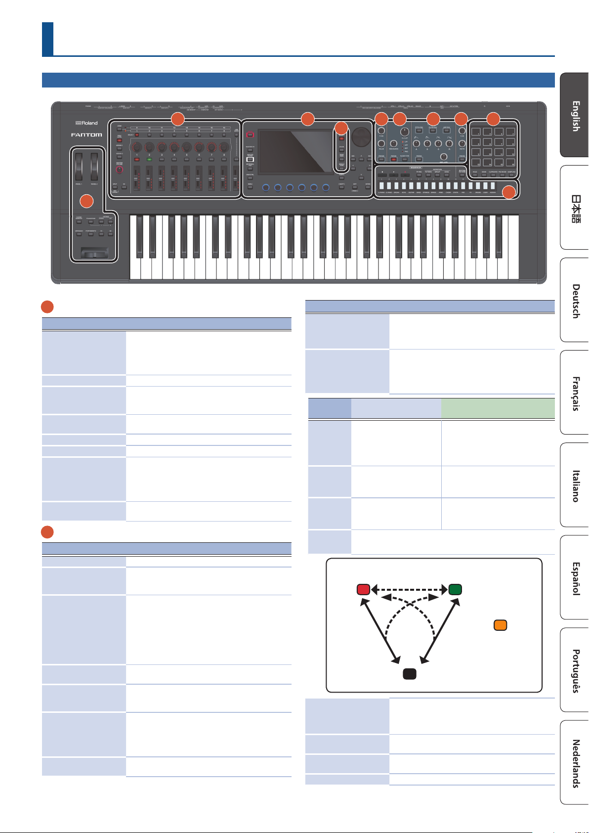
Top Panel
2 3
1
1
Controller section
Controller Explanation
You can assign various parameters or functions to these
WHEEL1
WHEEL2
[CHORD MEMORY] button Turns the chord memory function on/o.
[TRANSPOSE] button
OCTAVE [DOWN] [UP]
buttons
[ARPEGGIO] button Turns the arpeggiator on/o.
[PORTAMENTO] button Turns the portamento on/o.
[S1] [S2] buttons
Pitch bend/Modulation
lever
2
Zone section
Controller Explanation
[ZONE 1-8/9-16] button Switches the zones that you’re operating.
[PAN/LEVEL] button
[ASSIGN1] button
[ASSIGN2] button
[MASTER VOLUME] knob
[SPLIT/KEY RANGE]
button
[S3] button
ZONE SELECT buttons
[1]–[8]
wheels. To use the assigned function, move a wheel
while you perform.
If you operate the controller while holding down the
[SHIFT] button, the setting screen appears.
Hold down this button and use the OCTAVE [DOWN]
[UP] buttons to raise or lower the pitch range in
semitone steps.
Raise or lower the pitch range in steps of an octave.
Various parameters or functions can be assigned to
these buttons.
Hold down the [SHIFT] button and press one of these
buttons to access a screen that lets you assign a
function.
Varies the pitch or applies vibrato.
If you press the button to make it light, control knobs
[1]–[8] adjust the pan of each zone, and sliders [1]–[8]
adjust the volume of each zone.
Assign other functions to sliders [1]–[8] and control
knobs [1]–[8].
ASSIGN1 assigns parameters that you set for a scene,
and ASSIGN2 assigns parameters that you edit in
system settings.
Hold down the [SHIFT] button and press one of these
buttons to access a screen that lets you assign a
function.
Adjusts the volume that is output from the MAIN OUT
jacks and the PHONES jack.
Turns the split function on/o.
If you hold down the [SHIFT] button and press this
button, the key range setting screen appears.
Various parameters or functions can be assigned to
these buttons.
Hold down the [SHIFT] button and press one of these
buttons to access a screen that lets you assign a
function.
Select the zone that you want to control (the current
zone). The selected zone becomes the current zone.
5 6 7 8
10
4
9
Controller Explanation
Various parameters or functions can be assigned to
CONTROL knobs [1]–[8]
ZONE INT/EXT buttons
[1]–[8]
Button
status
Unlit
(COMMON)
Lit red
(INT)
Lit green
(EXT)
Lit orange
(MUTE)
Sliders [1]–[8]
[USB AUDIO SELECT]
button
[USB AUDIO IN/OUT]
button
[USB AUDIO] slider Adjusts the input level and output level of USB AUDIO.
When the applicable zone is
the current zone
The internal sound engine and
the external sound module both
produce sound when you play the
keyboard.
The internal sound engine
produces sound when you play
the keyboard.
The external sound module
produces sound when you play
the keyboard.
The sound engine is muted. The internal sound engine does not produce sound.
If the immediately previous state was lit green, the external sound module
produces sound.
Red
INT
ZONE INT/EXT
button
these knobs.
The parameters that can be controlled depend on the
function select buttons located at the left.
Specify whether the applicable zone does sound
or does not sound when you play the keyboard. In
conjunction with the current zone, this determines how
the internal sound engine (external sound module)
produces sound.
When the applicable zone is not the
current zone
Neither the internal sound engine nor the
external sound module produce sound
when you play the keyboard. You can use
the internal sequencer or MIDI data from an
external device to play the internal sound
engine.
Only if the ZONE INT/EXT button of another
current zone is on (lit red or green), the
internal sound engine produces sound
when you play the keyboard.
Only if the ZONE INT/EXT button of another
current zone is on (lit red or green), the
external sound module produces sound
when you play the keyboard.
[SHIFT] +
ZONE INT/EXT button
COMMON
Various parameters or functions can be assigned to
these sliders.
The parameters that can be controlled depend on the
function select buttons located at the left.
The USB AUDIO setting screen appears.
Switches the function of the USB AUDIO slider between
input and output, or turns the USB AUDIO function o.
Unlit
Green
ZONE INT/EXT
button
EXT
Orange
Set in the MIXER screen
MUTE
5
Page 6
Panel Descriptions
Type:LPF
CUTOFF
3
Common section
Controller Explanation
[WRITE] button
[MASTER FX] button
[ANALOG FILTER] button Accesses the analog lter editing screen.
[MOTIONAL PAD] button The MOTIONAL PAD screen appears.
[DAW CTRL] button Lets you use this unit as a DAW controller.
[MENU] button The MENU screen appears.
Display Shows various information depending on operation.
FUNCTION knobs [E1]–
[E6]
[TEMPO] button
[SHIFT] button
[VALUE] dial
[DEC] [INC] buttons
Cursor [H] [I] [K] [J]
buttons
[EXIT] button
[ENTER] button
4
Scene section
Controller Explanation
[SCENE SELECT] button
[SCENE CHAIN] button
[ZONE VIEW] button
[SINGLE TONE] button
5
OSC (Oscillator) section
Controller Explanation
[TYPE] knob Species the OSC type.
[VALUE] knob Lets you make OSC-related settings.
[PARAM] button
6
FILTER section
Controller Explanation
[CUTOFF] knob
The WRITE screen appears.
Saves a scene or tone.
The MASTER FX screen appears.
If you hold down the [SHIFT] button and press this
button, the MASTER EQ editing screen appears.
Turning a knob modies the function or parameter
value that is shown below in the screen. Pressing a
knob has the same result as a button operation.
The TEMPO screen appears.
You can set the tempo by repeatedly pressing the
button at the desired interval.
Accesses the corresponding edit screen when pressed
together with another button.
Changes a value.
If you hold down the [SHIFT] button and turn the dial,
the value changes more greatly.
Changes a value.
If you press one of these buttons while holding down
the other, the value changes more rapidly. If you press
one of these buttons while holding down the [SHIFT]
button, the value changes more greatly.
Move the cursor position up/down/left/right.
These buttons also switch between screens.
This button returns to the previous screen or closes the
open window.
Used to conrm a value, execute an operation, or view
lists or other items.
The SCENE SELECT screen appears.
Here you can select a scene.
The SCENE CHAIN screen appears.
This lets you recall scenes in a specied order.
The ZONE VIEW screen appears.
Here you can check the state of each zone.
Recalls a piano sound to zone 1. Zones other than 1 are
turned o.
NOTE
Note that when you press this button, unsaved scene
settings are lost.
Accesses the OSC setting screen of the TONE EDIT
ZOOM screen.
Species the cuto
frequency of lter.
RESONANCE
7
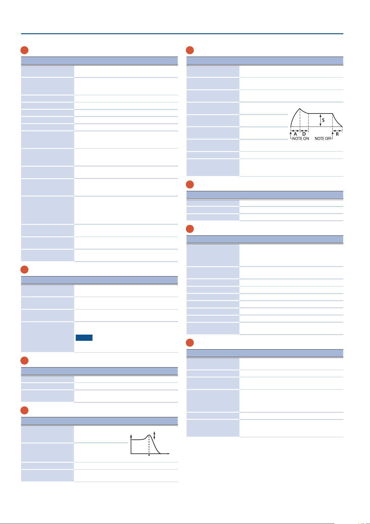
ENV/AMP section
Controller Explanation
[PITCH ENV] button
[FILTER ENV] button
[AMP ENV] button
[A] knob
[D] knob
[S] knob
[R] knob
[AMP LEVEL] knob Adjusts the volume.
[PARAM] button
8
EFFECTS section
Controller Explanation
[TYPE] knob Species the MFX TYPE of the selected zone.
[DEPTH] knob Species the MFX DEPTH of the selected zone.
[PARAM] button Accesses the MFX screen of EFFECTS EDIT.
9
Sequencer section
Controller Explanation
TONE CATEGORY buttons
[1]–[16]
[9STOP] button
[APLAY] button
[7REC] button
[TR-REC] button Enables TR-REC. (p. 20)
[PATTERN] button The PATTERN screen appears.
[GROUP] button The GROUP screen appears.
[SONG] button The SONG screen appears.
[RHYTHM PATTERN]
button
10
Pad section
Controller Explanation
[HOLD] button
[BANK] button Switches the pad bank.
[CLIP BOARD] button
[PAD MODE] button
[SAMPLING] button Lets you sample.
Pads [1]–[16]
Use the [A] [D] [S] [R] knobs to edit the pitch envelope
(time-varying change in pitch).
Use the [A] [D] [S] [R] knobs to edit the lter envelope
(time-varying change in cuto frequency).
Use the [A] [D] [S] [R] knobs to edit the amp envelope
(time-varying change in volume).
Species the attack time
of the envelope.
Species the decay time
of the envelope.
Species the sustain
level of the envelope.
Species the release
time of the envelope.
Accesses the TONE EDIT screen. The screen that appears
depends on the PITCH, FILTER, or AMP parameters that
are selected.
Select tones in each category.
Depending on the situation, these buttons are also
used for other things such as TR-REC input or as a
selector for the SCENE CHAIN function.
Stops pattern playback or recording, or stops playback
of the group or song.
Plays the pattern, group, or song.
Enters the record-standby condition.
The RHYTHM PATTERN screen appears.
Turns hold on/o (allowing the sound to continue even
after you release the pad).
Lets you move or copy a sample from one pad to
another.
Species the functions that are assigned to the pads.
Hold down the [SHIFT] button and press this button
to access the edit screen for the currently selected pad
mode and related screens.
Play the samples assigned to each pad.
You can make pad mode settings to assign various
functions to the pads.
[RESONANCE] knob
[FILTER TYPE] button Species the type of lter.
[PARAM] button
Species the resonance
of lter.
Accesses the FILTER setting screen of the TONE EDIT
ZOOM screen.
6
Page 7
2: HOT
3: COLD
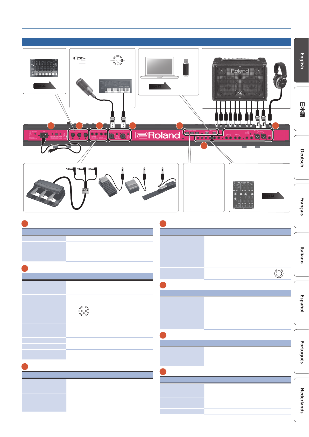
Rear Panel (Connecting the External Equipment)
1: GND
3: COLD
※ 入力端子の場合
1: GND 2: HOT
3: COLD
※ 出力端子の場合
Panel Descriptions
MIDI device
page 22
Pedal unit
(RPU-3)
A
Pin assignment of MIC/LINE INPUT jack
TIP: HOT
RING: COLD
SLEEVE: GND
Microphone Synthesizer
2: HOT
E F G
Computer
page 22
USB ash drive
Monitor speakers (powered)
Headphones
B D
C
Power cordto Power outlet
Expression pedal (EV-5)
Pedal switch (DP Series)
or
External USB device
Analog synthesizers or
Eurorack modules that are equipped
with CV/gate input jacks.
page 22
* To prevent malfunction and equipment failure, always turn down the volume, and turn o all the units before making any connections.
A
Power Supply
Controller Explanation
[POWER] switch This turns the power on/o.
Connect the included power cord to this connector.
AC IN jack
B
OUTPUT jack
Controller Explanation
PHONES jack
MAIN OUT jack (L, R)
(Balanced)
MAIN OUT jack
(L/MONO, R)
SUB OUT 1 jack (L, R)
SUB OUT 2 jack (L, R)
ANALOG FILTER OUT jack
(1, 2)
C
CV/GATE jacks
Controller Explanation
GATE OUT jack (1, 2)
CV OUT jack (1, 2)
* To prevent malfunction and equipment failure,
always turndown the volume, and turn o all the
units before making any connections.
A set of headphones can be connected to this jack.
Even if headphones are connected, an audio signal is sent
from the OUTPUT jacks and BALANCED OUT jacks.
These are balanced output jacks for audio signals.
Connect them to your mixer.
1: GND
These are output jacks for audio signals. Connect them
to your amp. If you’re outputting in mono, connect the
L/MONO jack.
These are output jacks for sub-out audio.
These output the sound that has passed through the
analog lter section.
These jacks output note-on/o. They output +5 V.
Depending on the settings, GATE OUT 2 can also be
used as CV OUT.
These jacks output pitch. If you’ve specied a transpose
or octave shift setting, the voltage changes according
to the setting.
These jacks support OCT/V (Hz/V is not supported).
* Pin assignment of MAIN
OUT jack
D
INPUT jack
Controller Explanation
Connect a mic, audio device, or external synthesizer etc. to
these jacks.
MIC/LINE INPUT jacks
(1, 2) (Balanced)
LEVEL knob (1, 2)
E
FOOT PEDAL jack
Controller Explanation
PEDAL jack (CTRL 1, CTRL
2/L, CTRL 3/C, HOLD/R)
F
MIDI jack
Controller Explanation
MIDI connectors (IN, OUT
1, OUT 2/THRU)
G
USB port
Controller Explanation
USB MEMORY port
USB COMPUTER port
EXT DEVICE jack (1, 2, 3) Connect these to an external USB device.
The MIC/LINE INPUT jacks support XLR-type and TRS-type
plugs. The XLR-type connections support 48 V phantom
power, allowing you to connect condenser mics that use
phantom power (phantom power supply: DC 48 V, 10 mA
Max).
Stereo input via a TRS plug is not supported.
Adjusts the input level of the MIC
INPUT jack.
If you connect a pedal switch (sold separately: DP series) to
the HOLD/R jack, you can use it as a damper pedal.
You can also assign various functions to the pedals that are
connected to the CTRL 1, CTRL 2/L, and CTRL 3/C jacks.
* Use only the specied expression pedal. By
connecting any other expression pedals, you risk
causing malfunction and/or damage to the unit.
Used for connecting external MIDI devices and for
transmission of MIDI messages.
The OUT 2/THRU connector’s function can be switched to
operate either as MIDI THRU or as MIDI OUT.
Use a commercially available USB ash drive. However, we
cannot guarantee that all commercially available USB ash
drives will work.
Connect this to your computer to transfer performance data
and audio signals.
MAX
MIN
7
Page 8

Introduction
Turning on the Power
* Once everything is properly connected, be sure to follow the procedure
below to turn on their power. If you turn on equipment in the wrong
order, you risk causing malfunction or equipment failure.
1. Minimize the volume of this unit.
Also completely turn down the volume of any connected external devices.
2. Press the [
The unit is turned on, and the display’s backlighting comes on.
3. Turn on the power to connected external devices.
4. Adjust the volume of the connected external devices.
5. Adjust the volume of this unit.
Turning o the Power
1.
Minimize the volume of this unit.
Also completely turn down the volume of any connected external devices.
2. Turn o the power of the connected external devices.
3. Press the [
The unit is turned o.
* Before turning the unit on/o, always be sure to turn the volume down.
Even with the volume turned down, you might hear some sound when
switching the unit on/o. However, this is normal and does not indicate
a malfunction.
* If you need to turn o the power completely, rst turn o the unit, then
unplug the power cord from the power outlet. Refer to “To completely
turn o power to the unit, pull out the plug from the outlet”
(p. 2).
L
] switch.
L
] switch.
Making the Power Automatically Turn o After a Time
(Auto O)
The power to this unit will be turned o automatically after a predetermined amount
of time has passed since it was last used for playing music, or its buttons or controls
were operated (Auto O function).
If you do not want the power to be turned o automatically, disengage the Auto
O function.
NOTE
5 Unsaved data is lost when the power turns o. Any data that you want
to keep must be saved in advance.
5 To restore power, turn the power on again.
Changing the Auto O Setting
1. Press the [MENU] button.
The MENU screen appears.
2. Touch <SYSTEM>.
The SYSTEM screen appears.
3. Touch <GENERAL>.
4. Select “Auto O” and change the setting.
Parameter Value Explanation
O The power will not turn o automatically.
Auto O
30 min
240 min
(default)
The power will automatically turn o if no
operation is performed for 30 minutes.
The power will automatically turn o if no
operation is performed for 240 minutes
(four hours).
5. If you want to store the auto-o setting, press the [WRITE]
button in the System screen.
8
Page 9

Basic Operation
Introduction
[VALUE] dialDisplay
[INC] [DEC] buttons
Cursor buttons
[SHIFT] button [EXIT] button [ENTER] button[MENU] button FUNCTION knobs [E1]–[E6]
Editing a Value
Use the following methods to modify a setting’s value.
[INC] [DEC] buttons
Press the [INC] button to increase the value; press the [DEC] button to decrease the value.
Purpose Operation
Modifying a value
continuously
Modifying a value rapidly
Modifying a value more
greatly
Hold down the [DEC] button or [INC] button.
Hold down the [INC] button and press the [DEC]
button. Hold down the [DEC] button and press the
[INC] button.
Hold down the [SHIFT] button and press the [DEC]
button. Hold down the [SHIFT] button and press
the [INC] button.
[VALUE] dial
Turn the dial clockwise to increase the value, or counter-clockwise to decrease the value.
Purpose Operation
Modifying a value more
greatly
Hold down the [SHIFT] button and turn the [VALUE]
dial.
Display (Touch panel)
You can directly touch or drag an on/o icon, knob icon, or slider icon in the screen to
switch a setting on/o or to edit a value.
NUMERIC window
If you hold down the [SHIFT] button and press the [ENTER] button, the numeric
window appears. This is a convenient way to directly enter a numeric parameter value
from the touch panel.
NOTE
Some parameters don’t support numeric input.
Moving the Cursor
Multiple setting items (parameters) or selection items are shown in a single screen or
window. To edit them using the [INC] / [DEC] buttons or the [VALUE] dial, move the
cursor to the location of the item you want to edit.
Use the following methods to move the cursor.
Cursor [H] [I] [K] [J] buttons
Press a cursor button to move the cursor in the corresponding direction.
Purpose Operation
Moving the cursor continuously
Moving the cursor rapidly
Hold down the cursor button.
While continuing to hold down one cursor button,
hold down the cursor button of the opposite
direction.
Display (Touch panel)
By directly touching a parameter value, knob icon, or slider icon in the screen, you can
move the cursor to that location.
NOTE
Some icons do not move the cursor.
Conrming or Canceling the Value
[ENTER] button
Use this button to conrm a value or execute an operation. When you move the
cursor to a tone or parameter and press the [ENTER] button, a list appears, allowing
you to change the setting.
[EXIT] button
This button returns to the previous screen, or closes the open window.
Display (Touch panel)
The <OK> or <SELECT> that are shown a conrmation screen have the same function
as the [ENTER] button, and <CANCEL> or <EXIT> have the same function as the [EXIT]
button.
[SHIFT] Button
This is used in conjunction with other buttons.
By holding down the [SHIFT] button and pressing another button, you can move to
the related edit screen for the button that you pressed (shortcut).
FUNCTION Knobs [E1]–[E6]
These knobs perform the functions that are assigned to them in each screen, such as
editing parameters or scrolling lists or tabs.
By pressing a knob, you can edit a value with a button-like operation.
Knob and Slider Operations
When you use a knob or slider to edit a setting,
the edited parameter and its value are shown in a
popup screen.
The popup screen closes automatically after a
time.
Some parameters don’t show a popup screen.
[MENU] Button
Allows you to make detailed settings for a function, or system settings. You can also
access the menu screen by touching the <
SCENE SELECT screen.
> icon located in the upper left of the
Operating procedures in this manual
On this unit, operations such as “editing a value,” “moving the cursor,” “setting/cancelling a value,” or “moving to a screen” can be performed on multiple ways, as explained
earlier. (For example, “button operations,” “touch panel operations,” “dial operations,” etc.)
To avoid making the subsequent explanations in this manual unnecessarily complex, we will not always describe all of these methods, but may simply provide an
abbreviated explanation such as “move the cursor to * and edit the value.” In actual operation, you may use any of the above methods as is convenient for you.
9
Page 10

Introduction
Operations in the Display
This unit’s display is a touch panel; you can perform various operations by directly
touching the display. There are many screens, but here we explain the typical screen
operations.
5 A light touch with your nger is sucient to operate the touch panel.
The touch panel might be damaged if you press it strongly, or if you
press it with a hard object. Do not use excessive force, and use only
your nger to operate it.
5 Text enclosed in [ ] indicates buttons shown in the panel. Text enclosed
in < > indicates buttons or knobs shown in the screen.
SCENE SELECT screen
Opens a menu. Touch to move between screens.
Switches to the next
(previous) page.
Touch to select a
scene.
ZONE VIEW screen
Touch to move the
cursor.
MENU screen
Returns to the screen of the next-higher level.
Touch to move
between screens.
Touch to turn a switch
on/o.
Touch to open
the list.
This shows information about the parameters that you can control using knobs [E1]–[E6].
TONE EDIT screen
Switches to the PRO
EDIT screen.
Touch to switch
between tabs.
Swipe to scroll.
This shows information about the parameters that you can control using knobs [E1]–[E6].
Touch to turn a switch
on/o or to select.
Touch to move the cursor.
Drag to edit a value.
TONE EDIT screen
Touch to close a
window.
Touch to move
between screens.
Touch to select a
parameter.
RENAME screen
Touch to enter characters.
Cancel.
MEMO
If you lose track of which screen you’re in, you can return to the SCENE
SELECT screen by pressing the [EXIT] button several times or by pressing
the [SCENE SELECT] button.
Conrm.
10
Drag to edit a value.
Page 11

Introduction
An Overview of This Unit
Broadly speaking, this unit consists of four sections: controller, synthesizer, sequencer,
and sampler.
Synthesizer
SamplerSequencer
Controller
Keyboard
Pitch bend
Pedal
Track1
Track2
Track3
Track4
Track10
Controller
Sliders
Knobs
Pads
Wheel
SynthesizerSequencer
Zone1
Zone2
Zone3
Zone4
Zone10
Units of Sound
TONE
A “tone” is the smallest unit of sound on this unit.
A tone consists of the combination of sound engine and eects (MFX+EQ).
Use the tone category buttons [1]–[16] to select tones by their category.
PRESET TONE USER TONE
Sound Engine Sound Engine
MFX MFXEQ EQ
You can edit a tone and then save it as a user tone.
Some tones are “drum kits” which provide a collection of percussion instrument
sounds.
In a drum kit, dierent percussion instrument sounds are heard depending on the key
(note number) that you play.
ZONE
This is a container for playing a tone.
To play a tone, you assign it to a zone. For each zone, you can specify whether it is
connected to the keyboard, and make settings such as its key range, volume, pan, and
controller reception.
There are 16 zones; by combining zones you can create sounds that consist of
multiple tones, or create foundational performance (sound) settings for each song.
You can also use specic zones to control an external sound module (EXT ZONE)
instead of the internal sound engine.
ZONE16
ZONE1
MIDI
USB
CV/GATE
Level, Pan
Key Range,
etc.
INTEXT
TONE
Level, Pan
Key Range,
etc.
Track16
Zone16
Sampler
Audio signal
Performance data
Controller
This includes the keyboard, pads, pitch bend/modulation lever, wheels, panel knobs,
sliders, and pedals connected to the rear panel. When you perform a performance
operation such as pressing or releasing a key or pressing the damper pedal, the
operation is converted into a MIDI message and transmitted to the sound engine and
to an external MIDI device.
Synthesizer
This is the section that generates and modies sound. In response to the performance
data from the controller, it produces an audio signal that is output from the OUTPUT
jacks and the PHONE jack.
Sequencer
This lets you create patterns using a 16-track MIDI sequencer. Tones of the 16 zones
in the scene can be recorded directly using the 16 tracks. Realtime recording, step
recording, and TR-REC are provided. You can combine patterns to create groups, and
place groups in the desired order to create a song.
Pattern
This is a unit of sequence data that records performance data for an individual tone. There can
be up to eight patterns in one track. You can record up to 32 measures in one pattern.
Group
This records a combination of patterns for each track. You can create up to 16 groups
in one scene.
Song
By placing groups in the desired order you can create a “song” that records that order.
You can create one song in one scene.
Sampler
The sampler section lets you audio-record (sample) the sound of your keyboard
performance or the input sound from an audio device or mic. The recorded sample
can be played by pressing a pad.
Sample
This is a piece of sampled sound. For each sample, you can specify looping and other
settings, and assign it to a pad.
SCENE
A scene contains a favorite performing state, including settings for each zone (tone,
MFX, volume, etc.), settings common to all zones (Reverb, Chorus, IFX, Analog Filter,
etc.), and sequence data for each zone.
You can store an idea for a song or phrase as a scene, and manage scenes by
switching them for each song.
You can freely recall saved scenes in the SCENE SELECT screen that appears after
startup.
By using the SCENE CHAIN function you can place and recall scenes in the order of
the songs that you’ll be playing live, or collect frequently-used scenes for easy recall.
(p. 15)
SCENE:A001
ZONE16
ZONE1
ANALOG FX
ARPEGGIO CHORD PA D
INTEXT
CHO
RHYTHM
TRACK16
TRACK1
PTN1 PTN8
GROUP
SEQUENCE DATA
SONGREVIFX2IFX1
11
Page 12

Performing
Selecting a Sound (SCENE/TONE)
Selecting a Scene
1. Press the [SCENE SELECT] button.
The SCENE SELECT screen appears.
2. Touch a scene icon in the screen to select the desired scene.
The icon of the selected scene is colored.
Sixteen scene icons are arranged in the screen as a 4 x 4 grid, and you can select one
of these scenes. By touching the K (J) icon located at the left or right edge of the
screen, you can choose from the previous (or next) 16 scenes.
Selecting a Tone
1. Press the [ZONE VIEW] button.
The ZONE VIEW screen appears.
Each time you press the [ZONE VIEW] button, the VIEW number (the number of
zones shown simultaneously) is switched.
1 ZONE VIEW 4 ZONE VIEW
Layering Zones (Layer)
1.
Press the ZONE INT/EXT button of the zones that you want to
layer, making them light red.
2. Of the zones that are lit, press the ZONE SELECT button of
one zone to specify it as the current zone.
When you play the keyboard, the zones lit red are sounded as layers.
NOTE
Zones whose ZONE INT/EXT button is lit green are controlling an external MIDI sound module.
To switch to the internal sound engine, once again hold down the [SHIFT] button and press the
corresponding ZONE INT/EXT button to make the button light red (INT setting).
Dividing the Keyboard into Two Regions (Split)
1.
Press the [SPLIT] button to make it light.
The high region plays the zone 1 tone, and the low region plays the zone 4 tone.
2. To cancel split, press the [SPLIT] button to make it go dark.
When you cancel split, the high and low regions (KEY RANGE) are reset, and return
to the layer state.
Changing the Keyboard’s Split Point
1. While holding down the [SPLIT] button, press the key that is
to become the new split point.
The split point is shown.
When you release the [SPLIT] button, the previous display will reappear.
The split-point key is included in the ZONE 1 section.
MEMO
5 If you want to change the tone of the upper key range, press ZONE
SELECT [1]; if you want to change the tone of the lower key range, press
ZONE SELECT [4]. Then select a tone.
5 By using the KEY RANGE function you can freely specify the key range
for each zone.
Raising/Lowering the Key Range in Semitones (Transpose)
1.
Hold down the [TRANSPOSE] button and press the OCTAVE
[DOWN] button or [UP] button.
5 You can change this setting in a range of -5–+6 semitones.
5 To return to the original setting, hold down the [TRANSPOSE] button
and press the OCTAVE [DOWN] button and [UP] button simultaneously.
8 ZONE VIEW16 ZONE VIEW
2. Press a ZONE SELECT button [1]–[8] to select the zone that
you want to control.
To select zones 9–16, use the [ZONE 1-8/9-16] button to switch groups, and then
press a ZONE SELECT [1]–[8] button.
3. Press a tone category button [1]–[16] to select the type
(category) of tone.
4. Move the cursor to the tone name (number), and use the
[VALUE] dial or the [INC][DEC] buttons to select a tone.
Cursor
5 When the cursor is located at the tone name (number), pressing the
[ENTER] button displays the “TONE LIST.”
Raising/Lowering the Key Range in Octaves (Octave)
1.
Press the OCTAVE [DOWN] button or [UP] button.
5 You can change this setting for a maximum of ±3 octaves.
5 To restore the original setting, press the OCTAVE [DOWN] button and
[UP] button simultaneously.
Playing Arpeggios
The arpeggiator is a function that automatically produces an arpeggio based on the keys that you press.
1. In ZONE VIEW, turn ARP "ON" for the applicable zone.
2. Press the [ARPEGGIO] button to make it light.
3. Play a chord on the keyboard.
According to the notes of the chord you play, an arpeggio starts playing for zones that are on.
4. Move the cursor to “STYLE” and change the style.
The arpeggio performance changes according to the selected style.
5. To turn o this function, press the [ARPEGGIO] button once
again to make it go dark.
MEMO
By using this in conjunction with the chord memory function, you can
easily play a variety of arpeggio sounds using just one nger.
12
Page 13

Performing
Playing Chords (Chord Memory)
Chord memory is a function that sounds a pre-registered chord form when you play a
single note on the keyboard.
1. Press the [CHORD MEMORY] button to make it light.
2. Play the keyboard.
A chord sounds according to the currently selected chord form.
3. Move the cursor to “CHORD FORM” and change the chord form.
The way in which the chord plays will change.
4. To turn o this function, press the [CHORD MEMORY] button
once again to make it go dark.
Selecting/Playing Rhythm Patterns
This unit lets you perform while a rhythm pattern plays.
1. Press the [RHYTHM PATTERN] button.
The RHYTHM PATTERN screen appears.
MEMO
You can hold down the [SHIFT] button and press the [ASSIGN1] or
[ASSIGN2] button to access the edit screen for assigning parameters. For
details, refer to “Reference Manual” (PDF).
Using the Analog Filter
This unit is equipped with an analog lter, providing a wide range of sound-design
potential.
1. Press the [ANALOG FILTER] button.
The Analog Filter screen appears.
2. Touch <EDIT>.
The ANALOG FILTER edit screen appears.
2. Move the cursor to “RHYTHM GROUP.”
3. Use the [VALUE] dial to select a rhythm group.
4. Touch <Intro>–<Ending> to select the rhythm pattern that
you want to play.
The rhythm pattern plays.
MEMO
To stop, touch the icon of the rhythm pattern that’s playing.
Changing the Tempo
1.
Press the [TEMPO] button to access the TEMPO screen.
2. Use the [VALUE] dial to change the tempo.
MEMO
You can specify the tempo by pressing the [TEMPO] button at the desired timing
(tap tempo). Press three times or more at quarter-note intervals of the desired
tempo.
Using the Sliders and Control Knobs
1.
Use the [ZONE 1-8/9-16] button to switch the zones (ZONE1–
ZONE8/ZONE9–ZONE16) that you want to control.
2. Press a function select button to select the parameter that
you want to control.
Button Explanation
[PAN/LEVEL] button
[ASSIGN1] button
[ASSIGN2] button
The control knobs adjust the pan of each zone, and
the sliders adjust the volume of each zone.
You can use the control knobs and sliders to adjust
the parameters that are assigned in advance to
the scene or the system. ASSIGN1 lets you adjust
the parameters that are assigned for each scene.
ASSIGN2 lets you assign the parameters that are
assigned for the system.
3. Move the cursor to the desired parameter, and edit the value.
Section Explanation
OVERDRIVE Adjusts the amount of distortion.
FILTER This is an analog lter with ve types.
Simultaneously Modifying the Volume of Multiple Zones (Motional Pad)
The motional pad function lets you simultaneously modify the volume of four zones
by dragging in the screen. By using the motional pad function, you can produce
diverse tonal changes with a single nger.
1. Press the [MOTIONAL PAD] button.
The MOTIONAL PAD screen appears.
The numbers of the zones being used with the motional pad function are shown
in the zone number areas at the four corners of the screen. If an applicable zone is
o, press the ZONE INT/EXT button [1]–[8] to turn the zone on.
Zone No.
Pointer
Zone No.
2. Drag the circle (pointer) in the center of the screen to change
its position.
The volume balance of the four zones changes according to the position of the
pointer, and the sound changes in real time.
3. Move the control knobs and sliders.
The sound changes according to the assigned function (such as pan or volume).
13
Page 14

Editing
Editing a Zone
There are 16 zones, and you can specify settings such as volume (Level), equalizer
(EQ), and key range (KBD) for each zone.
1. Select a scene.
2. Press the [MENU] button.
The MENU screen appears.
3. Touch <ZONE EDIT>.
The ZONE EDIT screen appears.
4. Press a ZONE SELECT button [1]–[8] to select the zone that
you want to control.
To select a zone 9–16, use the [ZONE 1-8/9-16] button to switch the group, and
then press a [1]–[8] button.
5. Move the cursor to the desired parameter, and edit the value.
You can use knobs [E1]–[E6] to scroll between tabs, move the cursor, and directly
edit parameters.
NOTE
Changes that you make to the zone settings are temporary. If you turn o
the power or select another zone, the changes are lost.
If you want to keep the edited settings, save the scene (p. 15).
MEMO
For details on the parameters, refer to “Parameter Guide” (PDF).
Editing a Tone
Here’s how to edit a tone.
1. As described in the procedure “Selecting a Tone” (p. 12),
select the tone that you want to edit.
2. Press the [MENU] button.
The MENU screen appears.
3. Touch <TONE EDIT>.
The TONE EDIT ZOOM screen appears.
4. Move the cursor to the desired parameter, and edit the value.
You can use knobs [E1]–[E6] to scroll between tabs and directly edit parameters.
MEMO
5 The TONE EDIT ZOOM screen diers depending on the tab that’s
selected.
5 For more detailed editing, use the TONE EDIT PRO screen. For details,
refer to “Reference Manual” (PDF).
5 For details on the tone parameters, refer to “Parameter Guide” (PDF).
5 In addition to editing in the TONE EDIT ZOOM screen, you can also edit
a tone directly by using the knobs and buttons of the OSC section,
FILTER section, and ENV/AMP section located at the right of the panel
(p. 5).
14
NOTE
Changes that you make to the tone settings are temporary. If you turn o
the power or select another tone, the changes are lost. If you want to keep
the edited settings, save the tone (p. 15).
Editing the Eects
This unit is equipped with a variety of eects, including an eect for each tone (MFX),
eects that can be specied for each scene (IFX1, IFX2, Chorus, Reverb), and eects
that can be specied for the system (Master FX).
ZONE1
TONE
MFX EQ
ZONE16
Chorus
Reverb
Comp x 6
for Drum Kit
IFX1
IFX2
Mixer
Master
FX
Master
Comp
Master
EQ
Analog
FX1
Analog
FX2
Output
Page 15

Editing
Editing the Tone’s Eect (MFX)
Here’s how to edit the tone’s eect (MFX).
1. Press the [MENU] button.
The MENU screen appears.
2. Touch <EFFECTS EDIT>.
The EFFECTS EDIT screen appears.
Turning the MFX on/o
1. In the screen, touch <MFX> to turn it on/o.
Editing the MFX parameters
1. In the MFX section, touch <EDIT>.
The EFFECTS EDIT (ZOOM) screen appears.
Saving a Scene or Tone
The edited zone and tone settings, and the recorded data, are temporary. They will be
lost if you turn o the power or select another scene or tone. If you want to keep your
edited settings or recorded data, save them as follows.
NOTE
When you save, the data previously located in the save-destination is
overwritten.
1. Press the [WRITE] button.
The WRITE MENU screen appears.
2. Touch the item that you want to save.
For example, if you touch <SCENE>, the SCENE WRITE screen appears.
3. If you want to change the name, touch <Rename> and edit the
name.
After changing the name, touch <OK> to close the window.
4. Use the [VALUE] dial or the [DEC][INC] buttons to select the
save-destination.
5. Touch <OK>.
A conrmation message appears.
To cancel, touch <CANCEL>.
6. Touch <OK>.
The data is saved.
2. In the MFX section, touch <EDIT>.
The EFFECT PRO EDIT screen for MFX appears.
3. Move the cursor to the desired parameter, and edit the value.
You can use the knobs [E1]–[E6] to move the cursor or edit parameters directly.
NOTE
The edits that you make to the eect settings are temporary. They will be
lost if you turn o the power or select another scene or tone. If you want
to keep the changes you made, save the tone, scene, or system settings
respectively.
MEMO
5 In addition to editing the eect settings in the screen, you can also edit
using the knobs and buttons of the EFFECTS section located in the right
side of the panel (p. 5).
5 For details on the parameters, refer to “Parameter Guide” (PDF).
Recalling Scenes in the Order of Songs (Scene Chain)
Use the SCENE CHAIN function when you want to recall scenes in the order of the
songs that you’ll be playing live.
A scene chain lets you specify the desired order of the scenes that you’ll be using,
without changing the numbers of the scenes themselves. The order of scenes can be
saved as a chain set, and by switching the chain set you can change the order of the
scenes.
1. Press the [SCENE CHAIN] button.
The SCENE CHAIN screen appears.
2. Touch the “CHAIN SET” name and switch chain sets.
A chain set lets you register the order of scenes. This is a convenient way to
arrange sounds in the order in which you’ll be playing them.
3. Press a tone category button [1]–[16] to select a scene.
The 16 scenes arranged horizontally in the screen correspond to tone category
buttons [1]–[16].
5 You can also select a scene by directly touching a scene icon in the
screen.
5 By touching the K (J) icon located at the left or right edge of the scene
icons, you can select the previous (or next) 16 scenes.
15
Page 16

Sampler
This unit lets you audio-record (sample) your keyboard or the input sound from an
audio device or mic. The recorded sample can be played by pressing a pad.
Playing a Sample by Pressing a Pad
Here we explain how you can use pads [1]–[16] to play sounds that you sampled.
(Sample Pad function)
In advance, select “SAMPLE PAD” as the pad function as described in “Assigning
Convenient Functions to the Pads (PAD MODE)” (p. 16).
1. Press a pad [1]–[16].
A sample plays.
You can press multiple pads to play them simultaneously.
Playing a Sample Continuously (Hold)
1.
While you hold down a pad, press the [HOLD] button.
The sample continues playing even after you release the pad. To stop the sample,
press the pad once again.
Switching Banks
The samples are assigned to four banks in units of 16 samples. When you switch
banks, the samples assigned to each pad will also switch.
1. Press the [BANK] button.
2. Press a pad [1]–[4] to select a bank.
If you experience stuck notes!
Press the [HOLD] button four times in rapid succession. This stops all sounds
that are being played by the pads.
Moving/Copying Samples
You can move or copy a sample to another pad.
Moving a Sample
1. Hold down the pad of the sample that you want to move, and
press the [CLIP BOARD] button.
2. Hold down the [CLIP BOARD] button, and press the move-
destination pad.
The sample is moved.
* If there is a sample in the move-destination pad, the message
“Overwrite OK?” appears. Press the [ENTER] button to overwrite, or
press the [EXIT] button to cancel.
Copying a Sample
1. Hold down the pad of the sample that you want to copy and
the [SHIFT] button; then press the [CLIP BOARD] button.
2. Hold down the [CLIP BOARD] button and press the copy-
destination pad.
The sample is copied.
* If there is a sample in the copy-destination pad, the message “Overwrite
OK?” appears. Press the [ENTER] button to overwrite, or press the [EXIT]
button to cancel.
Assigning convenient functions to the pads (PAD MODE)
By assigning various functions to the 16 pads, you can use them to select
scenes or play samples.
In addition to playing samples or selecting scenes, you can assign various
convenient functions to the pads.
1. Press the [PAD MODE] button.
2. Press a pad [1]–[16] button to select a function.
A setting screen appears according to the function you select.
MEMO
For details on each function, refer to “Reference Manual” (PDF).
16
Page 17

Sampler
Sampling
This unit lets you create a sample by sampling the following sounds.
5 Keyboard performance
5 Input from the MIC/LINE INPUT jacks 1, 2 (audio device, microphone)
5 Audio input from the USB COMPUTER port
1. As necessary, connect the device (audio device or mic) that
you want to sample to the MIC/LINE INPUT jacks 1 and 2.
MEMO
If you want to sample an audio device in stereo, connect the left channel to MIC/
LINE INPUT jack 1 and the right channel to MIC/LINE INPUT jack 2.
2. Press the [SAMPLING] button to make it blink.
The SAMPLING STANDBY screen appears.
3. Note that the <SAMPLE PAD> button shows the bank and
number of the sample pad to which the sound will be
sampled.
4. If you want to change the bank and number of the sample
pad, touch the <SAMPLE PAD> button.
In the SAMPLING DESTINATION (PAD) screen, specify the sample bank and
number that you want to change.
MEMO
If the pad you’re sampling already contains a sample, the message “Overwrite
OK?” appears. Press the [ENTER] button to overwrite, or press the [EXIT] button to
cancel.
5. Touch <Sampling Mode> to select the sampling mode.
Parameter Explanation
KBD+INPUT
KBD The keyboard performance is sampled.
INPUT
The keyboard performance together with the audio input from
the MIC/LINE INPUT jacks 1 and 2 and the audio input from the
USB COMPUTER port will be sampled.
The audio input from the MIC/LINE INPUT jacks 1 and 2 and the
audio input from the USB COMPUTER port will be sampled.
Parameter Value Explanation
Samples the sound as a single waveform.
MONO
Format
STEREO
AUTO TRIGGER
LEVEL
AUTO TRIGGER OFF, ON
0–15
Choose this if you’re using one mic and
sampling in mono.
If you’re inputting in stereo, the L and R sounds
are mixed and sampled.
Samples the sound of L and R as two
waveforms.
Choose this if you're sampling in stereo from a
source such as an audio device.
If Auto Trig is “ON,” sampling starts when a
signal that exceeds this setting is input.
If this is “ON,” sampling starts when a signal
that exceeds the AUTO TRIGGER LEVEL setting
is input.
If this is “OFF,” sampling starts immediately
when you touch <START>.
8. Produce sound on the device that’s connected to this unit,
and touch <START> at the moment that you want to start
sampling.
During sampling, the screen indicates “NOW SAMPLING!”
If AUTO TRIGGER is set “OFF” in step 7
Sampling starts when you touch <START>.
Produce sound on the device that’s connected to this unit.
If AUTO TRIGGER is set “ON” in step 7
Produce sound on the device that’s connected to this unit; sampling starts when
the input signal exceeds the setting specied by AUTO TRIGGER LEVEL.
When you want to stop sampling, touch <STOP>.
9.
Sampling stops, and the sample is saved to the sample destination pad.
MEMO
5 The sampled data is saved in this unit’s sample memory.
5 Audio data from your computer can be loaded as samples. For details,
refer to “Reference Manual” (PDF).
Deleting a Sample (Delete)
Here’s how to delete a sample.
1. Hold down the [SHIFT] button and press the [PAD MODE]
button.
The SAMPLE PAD screen appears.
6. Adjust the sampling volume.
Adjust the volume as high as possible without letting the level meter reach full
scale.
Device to sample Explanation
Audio device
Microphone
USB COMPUTER
Adjust the rear panel LEVEL
knobs 1 and 2, and the audio
device.
Adjust the rear panel LEVEL
knobs 1 and 2.
Adjust the USB Audio Input Level
(p. 22).
7. Make settings for sampling.
Touch an on-screen parameter to turn it on/o, or select a parameter and use the
[VALUE] dial to edit its value.
2. Press a pad to select the sample that you want to delete.
3. Touch <SAMPLE UTILITY>.
4. Touch <DELETE>.
A conrmation message appears.
To cancel, touch <CANCEL>.
5. Touch <OK>.
The sample is deleted.
Setting the Input Volume (Input Setting)
Here’s how to specify the input volume of the device connected to the MIC/LINE INPUT jacks
1 and 2.
1. In the SAMPLING STANDBY screen (p. 17), touch <INPUT
SETTING>.
2. Move the cursor to the desired parameter, and edit the value.
MEMO
For the input volume of the device connected to the USB COMPUTER port, see
“Adjusting the USB Audio Input” (p. 22).
17
Page 18

Sequencer
How the Sequencer Is Structured
Pattern
This unit’s sequencer lets you record and play back using 16 tracks which correspond
to the zones.
Each track can have up to eight patterns, and these variations are called patterns.
For each track, you can switch the variation during playback.
Each pattern can be up to 32 measures long, and will play as a loop of the length that
is specied for each pattern.
PATTERN
TRACK1
TRACK2
TRACK3
TRACK4
TRACK5
TRACK6
A
B
C
D
E
F
G
H
ZONE1 ZONE2 ZONE3 ZONE4 ZONE5 ZONE6
PLAY
PLAY
PLAY
PLAY
PLAY
PLAY
Group
The combination of patterns created for each track is called a group. You can create
groups such as “Intro,” “Verse,” or “Fill” corresponding to each section of your song.
GROUP
GROUP-01 :Intro
TRACK1
TRACK2
TRACK3
TRACK4
TRACK5
TRACK6
A
B
C
D
E
F
G
H
PLAY
PLAY
PLAY
PLAY
PLAY
PLAY
Song
The groups you create can be arranged into an order that’s called a song. You can
specify looping (LOOP) for individual groups and for the entire song.
SONG
Step1 Step2 Step3 Step4 Step5
TRACK16
PLAY
ZONE16
TRACK16
PLAY
Playing the Sequencer
Playing Pattern
1. Select a scene.
2. Press the [PATTERN] button.
The PATTERN screen appears.
A box in which a phrase is recorded (pattern box) is shown in color.
If you long-touch a track’s pattern box that’s already recorded, the pattern box
is shown highlighted. This means that it’s in play-standby mode, and will play
when you press the [PLAY] button. Only one pattern box for each track can be in
play-standby mode.
Empty
Exist Data
(Color Selectable)
Exist Data
Loop Sw OFF
Exist Data
Play Standby
Exist Data
Playing
3. Press the [APLAY] button.
Each track’s pattern that’s in play-standby mode will play.
5 If you touch a pattern box that’s not playing, the pattern you touch is
played.
5 By directly touching a colored pattern box in the screen, you can switch
patterns for each track.
4. If you press the [9STOP] button, pattern playback stops for
all tracks.
5 If you touch a pattern box that’s playing, only the pattern that you
touched stops.
5 If you switch or stop/start patterns while another pattern is playing,
the change automatically happens at measure boundaries of the other
playing pattern.
GROUP-01
Intro
GROUP-02
Verse1
GROUP-03
Verse2
GROUP-02
Verse1
MEMO
Patterns, groups, and songs are all saved for each scene.
18
GROUP-05
Ending
Page 19

Sequencer
Playing Group
1. Select a scene.
2. Press the [GROUP] button.
The GROUP screen appears.
Current Group Group List
5 The currently selected group (current group) is indicated by the cursor.
5 At the right of the screen is shown the pattern length for each track in
the current group, and you can use knob [E5] to specify the number of
measures for the group.
3. Press the [APLAY] button.
The current group plays.
4. Press the [9STOP] button to stop playback.
5. To select a dierent group, directly touch the group name to
select it.
You can also use the [E2] knob to make a selection.
Playing Song
1. Select a scene.
2. Press the [SONG] button.
The SONG screen appears.
A succession of boxes called group boxes is shown, each with a number indicating
the playback order.
Within each group box is shown information such as the group number, group
name, and the number of times it will loop. Nothing is shown in an empty group
box.
3. Press the [APLAY] button.
The song plays, and the groups play in the order in which they are placed.
The currently playing group (the current group) is indicated by a green group box.
4. Press the [9STOP] button to stop playback.
Recording a Pattern
There are three ways to record a pattern.
Realtime recording
(Realtime REC)
Step recording
(Step Rec)
TR-REC
Before you record, it’s a good idea to delete the existing pattern as follows.
Create a pattern by recording your keyboard performance and
controller operations just as you perform them.
Create a pattern by successively recording your keyboard
performance one step at a time.
This method lets you place notes of each instrument on the
steps at which you want them to be heard. This method is
suitable for creating drum patterns.
1. Select a scene.
NOTE
If you create a pattern, and then switch to another scene or turn o the power
without saving the scene, the data you created will be lost.
2. Press the [PATTERN] button.
The PATTERN screen appears.
3. Touch <PTN UTILITY>.
The PATTERN UTILITY screen appears.
4. Touch <DELETE>.
The DELETE MENU screen appears.
5. Touch <DELETE ALL>.
A conrmation message appears.
To cancel, touch <CANCEL>.
6. To execute, touch <OK>.
All patterns are deleted.
NOTE
Deleted patterns cannot be recovered.
Realtime Recording (Realtime REC)
1. Press the [7REC] button.
The REC STANDBY screen appears.
2. Make settings for recording.
Directly touch parameters in the screen to select them, or use the [VALUE] dial to
edit the value.
TRACK/PATTERN Recording Parameter
Recording
Parameter
Count In
Time Signature
Input Quantize Species the quantization that is applied during recording.
RHY SYNC
LOOP REC SW
REC EVENT
CLICK Turns the click (metronome) on/o.
Tempo Species the tempo.
Length Species the length of the pattern.
NEW/MIX
Since touching <TRACK/PATTERN> will take you to the PATTERN screen, use this
screen to select the track (1–16) and pattern (A–H) that will be recorded.
When you change the recording-destination track, the zone played by the track
moves in tandem.
(Example) Track 2: Zone 2 (Bass)0Track 10: Zone 10 (Drum)
After selecting a track and pattern in the PATTERN screen, press the [REC] button
once again.
Explanation
Adds a count-in when recording starts. Specify this before
you start recording (while stopped).
Species the time signature.
This can be specied when all patterns are empty.
Species whether the currently selected rhythm pattern
automatically plays back and is recorded when you start
recording (ON) or is not recorded (OFF).
ON: Continue recording even after you’ve recorded the
measures specied by the Length setting.
OFF: Transition from recording to playback when you’ve
recorded the measures specied by the Length setting.
Selects the performance data that will be recorded during
realtime recording.
Species whether to make a new recording or to overdubrecord.
3. Press the [APLAY] button to start recording.
You can also start recording by touching <START>.
4. Play the keyboard.
Knob and controller operations are also recorded.
5. Press the [9STOP] button to stop recording.
When you’ve nished recording, you can repeat steps 1–5 as necessary to record
pattern variations on the same track or to record another track.
If you’re creating groups or a song as described in the next section, it’s a good
idea to divide the recording into several tracks and create several patterns so that
you can distinguish them.
19
Page 20

Sequencer
Step Recording (Step REC)
1. Press the [7REC] button.
The REC STANDBY screen appears.
2. In <TRACK/PATTERN>, note the track that you’ll be recording.
TRACK/PATTERN
Since touching <TRACK/PATTERN> will take you to the PATTERN screen, use this
screen to select the track (1–16) and pattern (A–H) that will be recorded.
When you change the recording-destination track, the zone played by the track
moves in tandem.
(Example) Track 2: Zone 2 (Bass)0Track 10: Zone 10 (Drum)
After selecting a track and pattern in the PATTERN screen, press the [REC] button
once again.
3. Touch <STEP REC>.
The STEP RECORDING screen appears.
4. Specify the settings of the note that you will input.
Set the various recording parameters in the screen.
TR-REC
What is TR-REC?
TR-REC is the method of using the TONE CATEGORY buttons [1]–[16] to specify
the timing at which each instrument will sound.
TR-REC is available any time the phrase is playing or stopped. You can use it
while listening to a rhythm that you yourself created.
For example to create the drum pattern shown in gure 1, you would make the
settings shown in gure 2.
FIGURE 1
FIGURE 2
Step Number
Closed Hi-Hat
Snare Drum
Bass Drum
For the Drum part, playing an instrument on the keyboard makes the TONE
CATEGORY buttons [1]–[16] light or go dark to indicate the steps on which that
instrument will sound.
Pressing one of the TONE CATEGORY buttons [1]–[16] switches it between lit
and unlit,changing whether the instrument will or will not sound on that step.
01 0905 1303 1107 1502 1006 1404 1208 16
Button lit Button unlit
Recording Parameter
Recording Parameter Explanation
Note Type Selects the rhythmic value of the notes that you input.
Gate Time Species the gate time.
Velocity Species the velocity.
5. Play a key once.
The note is recorded in step 1, and the step position in the screen automatically
advances by the length of the step time.
You can record a chord by playing multiple notes.
6. Repeat step 6 to record each step.
7. Press the [EXIT] button to end recording.
MEMO
5 If you want to enter a rest, touch <REST>.
5 To delete the data from a step, touch <STEP BACK>.
5 To enter a tie, touch <TIE>.
5 If you want to cancel the previously-entered tie, touch <UNTIE>.
5 If you want to change the measure position at which you’re recording,
use knob [E6].
5 By using the keyboard scroll bar at the left edge of the screen, you can
move the displayed range of notes up or down.
5 By using the piano roll type scroll bar at the top of the screen, you can
move the displayed area through the measures.
1. Press the [7REC] button.
The REC STANDBY screen appears.
2. In <TRACK/PATTERN>, note the track that you’ll be recording.
TRACK/PATTERN
Since touching <TRACK/PATTERN> will take you to the PATTERN screen, use this
screen to select the track (1–16) and pattern (A–H) that will be recorded.
After selecting a track and pattern in the PATTERN screen, press the [REC] button
once again.
3. Touch <TR-REC>.
The TR-REC screen appears. The [TR-REC] button is lit, and tone category buttons
[1]–[16] change to operating as the TR-REC step buttons.
MEMO
You can also select the TR-REC function by pressing the [TR-REC] button
instead of the [7REC] button.
20
Page 21

Sequencer
4. Make TR-REC settings.
Set the various recording parameters in the screen.
Tone
Recording Parameter
Drum Kit
Recording Parameter
Recording Parameter Explanation
Scale Species the length of one step.
Gate Species the gate time.
Velocity Species the velocity.
5. Use the keyboard to specify the instrument that you want to
record (only for a drum kit).
The instrument changes when you press a key of a dierent pitch.
For tones other than a drum kit, use the keyboard to specify the pitch that you
want to input.
6. Press the tone category buttons [1]–[16] to illuminate the
steps at which you want a note to play.
˜
˜ ˜ ˜
Creating a Group
1.
Press the [PATTERN] button.
The PATTERN screen appears.
2. Here’s how to select patterns for each track to specify their
combination.
3. Touch <GROUPING>
The GROUP LIST appears.
4. Move the cursor to the number that you want to specify.
5. Touch <SET>.
A conrmation message appears.
To cancel, touch <CANCEL>.
6. To execute, touch <OK>.
The current combination of patterns for each track is registered as a group.
7. As necessary, repeat steps 2–6 to create groups.
You can touch <RENAME> and assign a name to the group that you create.
Creating a Song
1.
Press the [GROUP] button.
The GROUP screen appears.
2. Touch <MAKE SONG>.
The MAKE SONG screen appears.
HH
SD
BD
Notes are entered at the corresponding step locations in the screen.
To delete a note, press a lit tone category button [1]–[16] to make it go dark.
You can also press the [APLAY] button and enter notes while the pattern plays.
7. Press the lit [TR-REC] button to stop recording.
MEMO
5 You can’t select the TR-REC state during realtime recording or step
recording.
5 You can hold down the [SHIFT] button and press a tone category
button [1]–[4] to change the measure or beat location. (Depending
on the scale setting, use the [SHIFT] button + tone category buttons
[1]–[8]).
5 Scroll the keyboard (instrument) area in the left side of the screen to
move the display area up or down.
5 Use the piano-roll type scroll bar in the upper part of the screen to
move the display area through the measures.
3. In the GROUP LIST located at the left side of the screen, touch
<ADD> for the group that you want to play back rst.
The group you touch is added to the SONG eld at the right, and the input
position advances by one.
MEMO
5 If you touch <ADD/REPLACE> and use REPLACE to input, the group at
the input position is replaced.
5 A maximum of 32 groups can be input.
5 If you touch <BACK DEL>, the group at the input position is deleted,
and the input position returns by one.
4. Repeat step 3 as necessary to create your song.
NOTE
If after creating a group or song, you switch to another scene or turn o
the power without saving the scene, the data you created is lost.
21
Page 22

Control
Performing Live with a Plug-in Synthesizer
Here’s how you can use the FANTOM to play a plug-in synthesizer that’s installed on
your computer.
Performance using
Internal zones
Performance data for external
zones
(USB MIDI)
Plug-in synthesizer
installed on the computer
Audio from the
computer (USB audio)
Output
Connecting to Your Computer
The USB driver is software that transfers data between your computer software and
this unit.
You must install the USB driver in order to use this unit connected to your computer.
MEMO
For details on downloading and installing the USB driver, refer to the
Roland website.
http://www.roland.com/support/
USB Driver Settings
Here’s how to specify the USB driver that’s used when connecting to your
computer.
1. Press the [MENU] button.
2. Touch <SYSTEM>.
3. Touch <GENERAL> tab.
4. Set the “USB Driver” parameter to “VENDER.”
Parameter Value Explanation
VENDER
USB Driver
GENERIC
Choose this if you want to use a USB driver
downloaded from the Roland website.
Choose this if you want to use the standard USB
driver that was included with your computer.
* Only MIDI is available.
5. Press the [WRITE] button to save the SYSTEM settings.
6. Turn this unit’s power o, and then on again.
Controlling an External MIDI Device (EXT MIDI OUT)
This unit’s knob operations and keyboard performance can be transmitted as MIDI
messages from the MIDI OUT connector and from USB MIDI OUT.
Keyboard data can be output from the CV/GATE OUT jacks as CV/GATE signals.
By setting a specic zone to “EXT,” you can use that zone for controlling an external
MIDI device.
1. Press the ZONE SELECT button of the zone that you want to
use for MIDI output.
To select zones 9–16, use the [ZONE 1-8/9-16] button to switch groups, and then
press a ZONE SELECT [1]–[8] button.
2. Press the ZONE INT/EXT button of the selected zone to make
it light green.
If it's not green, hold down the [SHIFT] button and press the corresponding ZONE
INT/EXT button to make it light green (EXT setting).
If it is lit green (EXT setting), MIDI messages are output.
If the ZONE INT/EXT buttons of multiple zones are lit, these settings in
conjunction with the zones specied by the ZONE SELECT button (current zone)
determine whether MIDI is output to an external sound module (p. 12).
22
Button
status
Unlit
(COMMON)
Lit red
(INT)
Lit green
(EXT)
Lit orange
(MUTE)
When the applicable zone is
the current zone
The internal sound engine and
the external sound module both
produce sound when you play the
keyboard.
The internal sound engine
produces sound when you play
the keyboard.
The external sound module
produces sound when you play
the keyboard.
The sound engine is muted. The internal sound engine does not produce
sound. If the immediately previous state was lit green, the external sound
module produces sound.
When the applicable zone is not
the current zone
Neither the internal sound engine nor
the external sound module produce
sound when you play the keyboard. You
can use the internal sequencer or MIDI
data from an external device to play the
internal sound engine.
Only if the ZONE INT/EXT button of
another current zone is on (lit red or
green), the internal sound engine
produces sound when you play the
keyboard.
Only if the ZONE INT/EXT button of
another current zone is on (lit red or
green), the external sound module
produces sound when you play the
keyboard.
3. As desired, press the [PAN/LEVEL] button, the [ASSIGN 1]
button, or the [ASSIGN 2] button.
4. When you operate control knobs [1]–[8] and sliders [1]–[8],
MIDI messages are output according to the buttons you
pressed in step 3.
MEMO
5 You can make detailed settings in ZONE EDIT (p. 14).
5 The settings you make can be saved as scene settings. “Saving a Scene”
(p. 15)
Using USB Audio
Adjusting the USB Audio Input
Here’s how to make settings for audio that’s input from a USB-connected computer.
1. Press the [USB AUDIO SELECT] button.
The USB AUDIO menu appears.
2. Use the cursor to select “USB Audio Input Switch,” and use the
[VALUE] dial to turn the setting “ON.”
Audio input from the connected device turns on.
3. Use the cursor to select “USB Audio Input Volume,” and use
the [VALUE] dial to adjust the input level.
MEMO
If “USB Audio In/Out Select” is set to IN, you can also use the [USB AUDIO]
slider to adjust the value.
Adjusting the USB Audio Output
Here’s how to output the FANTOM’s audio to a USB-connected computer.
1. Press the [USB AUDIO SELECT] button.
The USB AUDIO menu appears.
2. Use the cursor to select “USB Audio Output Switch,” and use
the [VALUE] dial to turn the setting “ON.”
Audio output to the connected device turns on.
3. Use the cursor to select “USB Audio Output Volume,” and use
the [VALUE] dial to adjust the output level.
MEMO
If “USB Audio In/Out Select” is set to OUT, you can also use the [USB AUDIO]
slider to adjust the value.
Controlling an Analog Synthesizer (CV/GATE OUT)
You can connect an analog synthesizer equipped with CV/GATE input jacks, and
control its note on/o or pitch.
Jack Explanation
GATE OUT 1 jack
GATE OUT 2 jack
CV OUT 1 jack
CV OUT 2 jack
MEMO
GATE OUT2 can be changed to CV OUT. For details, refer to “Reference
Manual” (PDF).
These jacks output note on/o.
Outputs +5 V.
These jacks output pitch. If you’ve made transpose or octave
shift settings, this voltage changes accordingly.
These jacks support OCT/V (it does not support Hz/V ).
Page 23

Settings
Detailed Function Settings (Menu)
1.
Press the [MENU] button.
The MENU screen appears.
2. Touch the desired menu item in the screen.
3. Edit the settings of the selected menu.
MEMO
For details on the contents of each menu item, refer to “Reference
Manual” (PDF).
Menu Explanation
TONE EDIT Edit a tone (p. 14).
EFFECTS EDIT Edit the eects (p. 14).
ZONE EDIT Edit a zone (p. 14).
SCENE EDIT Make settings for an entire scene (p. 12).
MIXER Adjust the pan and the volume balance.
SYSTEM Make overall settings for the entire this unit.
UTILITY Back up data or initialize this unit (p. 23).
Backing up User Data (Backup/Restore)
Here’s how all settings stored in this unit’s internal memory can be saved to an USB
ash drive (backed up), or written back into internal memory (restored).
Saving Data to USB Flash Drive (BACKUP)
NOTE
If you back up using the same le name as backup data that already exists
on the USB ash drive, the existing data will be overwritten. Assign a
dierent name if you want to make a new backup.
1. Press the [MENU] button.
The MENU screen appears.
2. Touch <UTILITY>.
The UTILITY screen appears.
3. Touch <BACKUP>.
4. If you want to rename the backup le, touch <RENAME> and
assign a name (p. 10).
After editing the name, touch <OK> to close the window.
5. Touch <OK>.
A conrmation message appears.
To cancel, touch <CANCEL>.
6. To execute, touch <OK>.
NOTE
Never turn o the power or remove the USB ash drives while the
screen indicates “working.”
Restoring Saved Data from USB Flash Drive (RESTORE)
NOTE
When you execute the restore operation, all settings currently saved in this
unit will be lost. If you want to keep the current settings, back them up
using a dierent name.
1. In the UTILITY screen, touch <RESTORE>.
2. Touch the le that you want to restore, and then touch
<RESTORE>.
A conrmation message appears.
To cancel, touch <CANCEL>.
3. To execute, touch <OK>.
NOTE
Never turn o the power or remove the USB ash drives while the
screen indicates “working.”
4. Turn the power o, and then on again (p. 8).
Returning to the Factory Settings (Factory Reset)
Here’s how you can restore this unit’s settings to their factory-set condition
(factory reset).
NOTE
When you execute the Factory Reset operation, all data in this unit will be
lost. If there is any data that you want to keep, back it up to an USB ash
drive.
1. In the MENU screen, touch <UTILITY>.
2. Touch <FACTORY RESET>.
A conrmation message appears.
To cancel, touch <CANCEL>.
3. To execute, touch <OK>.
NOTE
Never turn o the power while the factory reset is in progress.
Main Specications
Roland FANTOM : Music Workstation
FANTOM-6 FANTOM-7 FANTOM-8
Keyboard
Power
Supply
Current
Draw
Dimensions
Weight
Accessories
Options
61 Keys semi-weighted keyboard and channel aftertouch
AC 117-240 V
50W
1,084 (W) x 403 (D) x 106 (H) mm
42-11/16 (W) x 15-7/8 (D) x 4-3/16 (H) inches
15.3 kg
33 lbs 12 oz
Owner’s Manual
Power Cord
Keyboard stand: KS-10Z, KS-12 Keyboard stand: KS-10Z, KS-12
Pedal Switch: DP series, RPU-3
Expression Pedal: EV-5
USB ash drive (*1)
*1 Use a commercially available USB ash drive. However, we cannot guarantee that all commercially available USB
ash drives will work
.
76 Keys semi-weighted keyboard and channel aftertouch
1,296 (W) x 403 (D) x 106 (H) mm
51-1/16 (W) x 15-7/8 (D) x 4-3/16 (H) inches
17.7 kg
39 lbs 1 oz
* This document explains the specications of the product at the time
that the document was issued. For the latest information, refer to the
Roland website.
MEMO
For details on how to place this unit on a stand, refer to “Reference
Manual” (PDF).
88 Keys PHA-50 Wood and
Plastic Hybrid Structure and
channel aftertouch
1,432 (W) x 439 (D) x 153 (H) mm
56-7/16 (W) x 17-5/16 (D) x 6-1/16 (H) inches
27.7 kg
61 lbs 2 oz
Keyboard stand: KS-G8B, KS10Z, KS-12
23
Page 24

 Loading...