

Page 1

Parameter Guide
© 2022 Roland Corporation 01
Page 2

Contents
Scene Parameters (Scene) ...........................4
SCENE ...................................................4
GENERAL ..............................................4
CONTROL ..............................................4
PEDAL .................................................4
KNOB ..................................................5
SLIDER .................................................5
S1/S2 ..................................................5
WHEEL1/2 ..............................................6
VOCODER ..............................................6
SONG ..................................................6
Scene Eect Parameters (SCENE EFFECT) ..............7
Chorus ...................................................7
Chorus. . . . . . . . . . . . . . . . . . . . . . . . . . . . . . . . . . . . . . . . . . . . . . . . .7
CE-1 ...................................................7
SDD-320 ...............................................7
Delay ..................................................7
T-Ctrl Delay. . . . . . . . . . . . . . . . . . . . . . . . . . . . . . . . . . . . . . . . . . . . .7
Delay Ó Tremolo ........................................8
2Tap Pan Delay .........................................8
3Tap Pan Delay .........................................8
JUNO-106 Chorus .......................................8
Reverb ...................................................8
INTEGRA-7 Reverb ......................................9
Warm Hall ..............................................9
Hall ...................................................9
GS Reverb ..............................................9
SRV-2000 ............................................ 10
SRV-2000 NON-LINEAR ................................ 10
GM2 Reverb .......................................... 10
IFX1, IFX2 .............................................. 11
VOCODER SETTING ..................................... 11
Zone Parameters (Zone) ............................12
INT (INTERNAL) ........................................... 12
TONE ................................................ 12
LEVEL/PAN ........................................... 12
KEY RANGE ........................................... 12
VEL RANGE ........................................... 12
(Zone EQ) ........................................... 13
EQ
PITCH ................................................ 13
SCALE TUNE .......................................... 13
VIBRATO ............................................. 14
OFFSET .............................................. 14
MONO/POLY ......................................... 14
PEDAL CTRL .......................................... 15
BEND CTRL ........................................... 15
S1S2 CTRL ............................................ 15
ASSIGN KNOB ........................................ 15
ASSIGN SLIDER ....................................... 15
VOICE RESERVE ....................................... 16
MIDI Rx FILTER ........................................ 16
(EXTERNAL) .......................................... 16
EXT
NAME ............................................... 16
OUT/PC .............................................. 16
LEVEL/PAN ........................................... 16
KEY RANGE ........................................... 17
VEL RANGE ........................................... 17
PITCH ................................................ 17
OFFSET .............................................. 17
MONO/POLY ......................................... 18
PEDAL CTRL .......................................... 18
BEND CTRL ........................................... 18
S1S2 CTRL ............................................ 18
ASSIGN KNOB ........................................ 19
ASSIGN SLIDER ....................................... 19
ZEN-Core Tone Parameters (Z-Core) .................20
COMMON ............................................ 20
STRUCTURE .......................................... 22
KEYBOARD ........................................... 24
OSC ................................................. 24
PITCH ................................................ 26
PITCH ENV ........................................... 27
FILTER ............................................... 28
FILTER ENV ........................................... 29
AMP ................................................. 30
AMP ENV ............................................. 31
LFO1 / LFO2 .......................................... 31
STEP LFO1 / STEP LFO2 ................................ 32
PARTIAL EQ .......................................... 33
OUTPUT ............................................. 34
CONTROL ............................................ 34
MATRIX CONTROL ..................................... 34
MFX ................................................. 36
MFX CTRL ............................................ 36
22
Page 3

Drum Kit Tone Parameters (Drum) ..................37
KIT COMMON ......................................... 37
KIT MFX .............................................. 37
KIT MFX CTRL ......................................... 37
KIT COMP1–6 ......................................... 37
KEY PARAM. . . . . . . . . . . . . . . . . . . . . . . . . . . . . . . . . . . . . . . . . . . 37
KEY EQ .............................................. 38
INST COMMON ....................................... 38
INST WAVE ........................................... 39
INST WMT ............................................ 40
PITCH ENV ........................................... 40
INST FILTER ........................................... 41
FILTER ENV ........................................... 42
INST AMP ............................................ 43
AMP ENV ............................................. 43
VTW Tone Parameter (VTW) ........................44
COMMON ............................................ 44
WHEEL ............................................... 44
Overdrive ............................................ 45
Rotary ............................................... 46
MFX ................................................. 46
MFX CTRL ............................................ 47
VTW Control ......................................... 47
Contents
SuperNATURAL Acoustic Tone Parameter ..........48
COMMON ............................................ 48
INST ................................................. 48
MFX ................................................. 48
MFX CTRL ............................................ 48
SuperNATURAL Inst Parameter .......................... 49
SuperNATURAL Acoustic Piano/E.Piano Tone Parameter ..52
COMMON ............................................ 52
INST ................................................. 52
MFX ................................................. 52
MFX CTRL ............................................ 52
SuperNATURAL Inst Parameter .......................... 52
System Eect Parameters (SYSTEM EFFECT) ...........54
Master FX (MASTER FX) .................................... 54
Mastering COMP ...................................... 54
Mastering EQ ......................................... 54
TFX .................................................. 55
Audio in Eect
LOW CUT ............................................ 55
VOCODER ............................................ 55
NOISE SUPRESSOR .................................... 55
MFX ................................................. 55
INPUT EQ ............................................ 55
INPUT REVERB ........................................ 55
(AUDIO IN EFFECT) ........................... 55
MFX/IFX Parameters ..............................56
Note .................................................. 102
33
Page 4

Scene Parameters (Scene)
SCENE
1. Press the [MENU] button.
The MENU screen appears.
2. Touch <SCENE EDIT>.
The SCENE EDIT screen appears.
3. Touch the tab of the section that you want to edit.
4. Move the cursor to the desired parameter, and
edit its value.
NOTE
The parameter edits that you make are temporary. They are lost when
you turn o the power. If you want to keep the edits that you make,
save the scene.
GENERAL
Parameter Value Explanation
Scene Level 0–127
Tempo 5.00–300.00
SYSTEM Use the system’s PAD MODE settings.
SAMPLE PAD Plays a sample.
NOTE PAD Use the pads to play tones.
PARTIAL SW/
SEL
DAW CONTROL Control DAW software.
ZONE MUTE Turn zone muting on/off.
Pad Mode
Pad Zone
Select
Drum Kit
Comp Zone
ZONE SOLO Turn zone solo on/off.
KBD SW
GROUP
RHYTHM
PATTERN
PATTERN
VARIATION
PLAY
GROUP PLAY Plays back the sequencer group.
1–16, OFF
1–16
Adjusts the overall volume of the
scene.
Specifies the tempo of the scene
(and also of the arpeggios, rhythm
patterns, and sequencer).
Select partials or turn them on/off.
Turns the keyboard switch
combination.
Play rhythm patterns.
The pads play the patterns of the
pattern sequencer.
The pads play the pattern variations.
Specifies the pad zone
records performance data of the sample
.
pads)
The zone selected here can play the
sample pads instead of the internal
sound engine.
Selects the zone that uses the six
compressors that are provided for the
drum kit.
(the zone that
CONTROL
Parameter Value Explanation
System Control Source1–4 are used
for tone control.
Tone Control Source1–4 of the scene
are used for tone control.
Specify the MIDI messages that will be
used as tone controls.
Tone control settings specify MIDI
messages that are used in common
by the entire FANTOM to control the
volume and the sound.
You can specify up to four MIDI
messages that are used for control.
If you want to make assignments for
realtime control of the sound and
effects for each tone independently,
use “MATRIX CTRL” or “MFX CTRL”.
Control Source
Select
Tone Control
Source1–4
SYS
SCENE
OFF, CC01–31,
33–95, BEND,
AFT
PEDAL
Parameter Value Explanation
Specify the functions that are controlled by pedals
connected to the PEDAL CTRL 1, 2 jacks.
OFF No function is assigned.
Pedal1, 2
Assign
CC01–31,
33–95
BEND DOWN
BEND UP
AFT Aftertouch
START/STOP Starts/stops the sequencer.
TAP TEMPO Sets the tap tempo function.
SCENE DOWN
SCENE UP
OCT DOWN
OCT UP
ARPEGGIO SW
CHORD MEM
SW
DEC
INC
VOCODER SW Turns the vocoder on/off.
VTW ROTARY
SPEED
Controller numbers 1–31, 33–95
The same effect as moving the pitch
bend lever to the left.
The same effect as moving the pitch
bend lever to the right.
Switch the scene to the previous
number. When using a scene chain,
switch to the previous number in the
chain set.
Switch the scene to the next number.
When using a scene chain, switch to
the next number in the chain set.
Applies the same effect as when the
panel’s OCTAVE [DOWN] button is
pressed.
Applies the same effect as when the
panel’s OCTAVE [UP] button is pressed.
Applies the same effect as when the
panel’s [ARPEGGIO] button is pressed.
Applies the same effect as when the
panel’s [CHORD MEMORY] button is
pressed.
Applies the same effect as when the
panel’s [DEC] button is pressed.
Applies the same effect as when the
panel’s [INC] button is pressed.
Alternates between SLOW and FAST.
44
Page 5

Scene Parameters (Scene)
Parameter Value Explanation
Pedal1, 2
Assign
Pedal1, 2
Range Min
Pedal1, 2
Range Max
VTW ROTARY
BRAKE
VTW ROTARY
SW
VTW
OVERDRIVE SW
VTW WHEEL
BRAKE
VTW VIB/CHO SWLets you switch the vibrato and
0–127
0–127
Alternately switches the brake on/off
for the rotary effect.
Turns the rotary effect ON/OFF.
Lets you switch the overdrive on/off.
Alternately switches the brake on/off
for the tonewheel.
chorus on/off.
Specifies the lower limit of the range
of the assigned function.
Specifies the upper limit of the range
of the assigned function.
KNOB
Parameter Value Explanation
Knob/Slider
Func Select
Knob1–8
Assign
Knob1–8
Range Min
Knob1–8
Range Max
Sets the functions for the control knobs and sliders.
Specifies the function that is controlled by the control
knob.
OFF No function is assigned.
CC01–31,
33–95
BEND
AFT Aftertouch
0–127
0–127
Controller numbers 1–31, 33–95
Applies the same effect as when the
pitch bend lever is moved.
Specifies the lower limit of the range
of the assigned function.
Specifies the upper limit of the range
of the assigned function.
SLIDER
Parameter Value Explanation
Knob/Slider
Func Select
Slider1–8
Assign
Slider1–8
Range Min
Slider1–8
Range Max
Sets the functions for the control knobs and sliders.
Specifies the function that is controlled by the sliders.
OFF No function is assigned.
CC01–31,
33–95
BEND
AFT Aftertouch
0–127
0–127
Controller numbers 1–31, 33–95
Applies the same effect as when the
pitch bend lever is moved.
Specifies the lower limit of the range
of the assigned function.
Specifies the upper limit of the range
of the assigned function.
S1/S2
Parameter Value Explanation
Specifies the function that is controlled by the [S1] [S2]
buttons.
OFF No function is assigned.
CC01–31,
33–95
BEND DOWN
BEND UP
AFT Aftertouch
MONO/POLY Mono/poly switch is assigned.
MFX SW MFX on/off is assigned.
EQ SW EQ on/off is assigned.
IFX1 SW IFX 1 on/off is assigned.
IFX2 SW IFX 2 on/off is assigned.
CHORUS SW CHORUS on/off is assigned.
REVERB SW REVERB on/off is assigned.
MASTER COMP
SW
MASTER EQ SW MASTER EQ on/off is assigned.
VOCODER SW Turns the vocoder on/off.
SCENE DOWN
SCENE UP
S1, S2 Switch
Assign
DEC
INC
START/STOP Plays/stops the sequencer.
GROUP PLAY
DOWN
GROUP PLAY UPSelects the next group in the group
SONG LOOP
SW
TFX SW Turn the TFX on/off.
MASTER KEY
DOWN
MASTER KEY UPAdjusts the Master Key Shift value
SCALE TUNE
SW
VTW ROTARY
SPEED
VTW ROTARY
BRAKE
VTW ROTARY
SW
VTW
OVERDIRVE SW
VTW WHEEL
BRAKE
Controller numbers 1–31, 33–95
The same effect as moving the pitch
bend lever to the left.
The same effect as moving the pitch
bend lever to the right.
MASTER COMP on/off is assigned.
Switches the scene to the previous
number. Switches to the previous
number in the chain set when using a
scene chain.
Switches the scene to the next
number. Switches to the next number
in the chain set when using a scene
chain.
The same effect is applied as when
the [DEC] button on the panel is
pressed.
The same effect is applied as when
the [INC] button on the panel is
pressed.
Selects the previous group in the
group list.
list.
Turns the song loop on/off.
Adjusts the Master Key Shift value
by -1.
by +1.
Turns the SCALE TUNE on/off.
Alternates between SLOW and FAST.
Alternately switches the brake on/off
for the rotary effect.
Turns the rotary effect ON/OFF.
Lets you switch the overdrive on/off.
Alternately switches the brake on/off
for the tonewheel.
55
Page 6

Scene Parameters (Scene)
Parameter Value Explanation
VTW VIB/CHO SWLets you switch the vibrato and
chorus on/off.
S1, S2 Switch
Assign
S1, S2 Switch
Mode
VTW
HARMONIC
BAR
Specifies the operation of the button.
MOMENTARY
LATCH
You can also use the sliders as
harmonic bars on other screens
besides the edit screen. Settings can
be made for only the [S1] and [S2]
buttons.
The assigned function is effective only
while you hold down the button.
The assigned function is switched
each time you press the button.
WHEEL1/2
Parameter Value Explanation
Specifies the function that is controlled by the wheel.
OFF No function is assigned.
Wheel1–2
Assign
Wheel1–2
Range Min
Wheel1–2
Range Max
CC01–31,
33–95
BEND
AFT Aftertouch
0–127
0–127
Controller numbers 1–31, 33–95
Applies the same effect as when the
pitch bend lever is moved.
Specifies the lower limit of the range
of the assigned function.
Specifies the upper limit of the range
of the assigned function.
VOCODER
Parameter Value Explanation
Vocoder
Switch
Vocoder
Setting Bank
Vocoder
Setting
Number
Vocoder Zone
Select (Zone1–
Zone16)
OFF, ON Turns the vocoder on/off.
PRESET, USER Selects the VOCODER SETTING bank.
PRESET: 001–010,
USER: 001–020
OFF, ON
Selects the VOCODER SETTING
number.
¹ Specifies the zone that is used as
the vocoder carrier. Zones that are
ON are used as the vocoder carrier.
¹ If you want to select multiple
zones, you must match the on/
off status of each ZONE INT/EXT
button.
SONG
Parameter Value Explanation
SEQUENCE
TYPE
SEQ, SMF
PLAYER
Sets whether to use the sequencer or
the SMF Player.
66
Page 7

Scene Eect Parameters (SCENE EFFECT)
1. Press the [MENU] button.
The MENU screen appears.
2. Touch <EFFECTS EDIT>.
The EFFECTS EDIT screen appears.
3. Touch <EDIT> for the section that you want to
edit.
4. Move the cursor to the desired parameter, and
edit its value.
NOTE
The eect settings that you edit are temporary. They will disappear if
you turn o the power. If you want to keep your changes, you must
save the system settings.
Chorus
Parameter Value Explanation
Chorus Type Selects the types of chorus.
Chorus Switch OFF, ON Switches chorus on/off.
Chorus Level 0–127
Reverb Send
Level
Chorus Output
Assign
Chorus
Parameters
0–127 Specifies the send level to reverb.
Selects the output destination of chorus.
MAIN Send to Master Output.
SUB Send to the SUB OUT jacks.
Edit the parameters of the selected chorus. The
available parameters differ depending on the type of
chorus you selected in Chorus Type.
Chorus Parameters
Chorus
This is a stereo chorus.
Parameter Value Explanation
Rate 0–127 Frequency of modulation
Depth 0–127 Depth of modulation
Feedback 0–127
CE-1
This models the classic BOSS CE-1 chorus eect unit. It provides a
chorus sound with a distinctively analog warmth.
Specifies the output level of the
sound with chorus applied.
Level at which chorus sound is
returned to the input
SDD-320
This models Roland’s DIMENSION D (SDD-320). It provides a clear
chorus sound.
Parameter Value Explanation
Mode
1–4, 1+4, 2+4,
3+4
Switches the mode.
Delay
This is a stereo delay.
Parameter Value Explanation
Delay (sync sw) OFF, ON
Delay (msec)
Delay (note)
Feedback -98–+98 [%]
HF Damp
1–1300 [msec]
Note
Ø “Note” (p. 102)
200–8000 [Hz],
BYPASS
If this is ON, the delay synchronizes
with the tempo.
Adjusts the delay time from the direct
sound until the delay sound is heard.
Adjusts the proportion of the delay
sound that is fed back into the effect.
Negative (-) settings will invert the
phase.
Adjusts the frequency above which
the delay sound fed back to the effect
is filtered out (BYPASS: no cut).
T-Ctrl Delay
A stereo delay in which the delay time can be varied smoothly.
Parameter Value Explanation
Delay (sync sw) OFF, ON
Delay (msec)
Delay (note)
Acceleration 0–15
Feedback -98–+98 [%]
HF Damp
1–1300 [msec]
Note
Ø “Note” (p. 102)
200–8000 [Hz],
BYPASS
If this is ON, the delay synchronizes
with the tempo.
Adjusts the delay time from the direct
sound until the delay sound is heard.
When you change the delay time,
this specifies the time over which the
current delay time changes to the
specified delay time. This affects the
speed of pitch change as well as the
delay time.
Adjusts the proportion of the delay
sound that is fed back into the effect.
Negative (-) settings will invert the
phase.
Adjusts the frequency above which
the delay sound fed back to the effect
is filtered out (BYPASS: no cut).
Parameter Value Explanation
Intensity 0–127 Chorus depth
77
Page 8
Scene Eect Parameters (SCENE EFFECT)
Delay Ó Tremolo
Tremolo is applied to the delay sound.
Parameter Value Explanation
Input Mode
Delay (sync sw) OFF, ON
Delay (msec)
Delay (note)
Feedback -98–+98 [%]
HF Damp
Tremolo
Switch
Tremolo Mod
Wave
Tremolo Rate
(sync sw)
Tremolo Rate
(Hz)
Tremolo Rate
(note)
Tremolo Depth 0–127 Tremolo depth
MONAURAL The input is mono-mixed.
STEREO The sound is input in stereo.
If this is ON, the delay synchronizes
with the tempo.
1–1300 [msec]
Note
Ø “Note” (p. 102)
200–8000 [Hz],
BYPASS
OFF, ON Switches the tremolo effect on/off
Modulation Wave
TRI Triangle wave
SQR Square wave
SIN Sine wave
SAW1
SAW2
TRP Trapezoidal wave
OFF, ON
0.05–10.00 [Hz]
Note
Ø “Note” (p. 102)
Adjusts the delay time from the direct
sound until the delay sound is heard.
Adjusts the proportion of the delay
sound that is fed back into the effect.
Negative (-) settings will invert the
phase.
Adjusts the frequency above which
the delay sound fed back to the effect
is filtered out (BYPASS: no cut).
Sawtooth wave
If this is ON, the tremolo synchronizes
with the tempo.
Tremolo rate
3Tap Pan Delay
Delayed sound is heard from the three locations you specify.
Parameter Value Explanation
Delay (sync sw) OFF, ON
Delay (msec)
Delay (note)
Delay1
Feedback
HF Damp
Delay 1 Pan L64–63R Stereo location of Delay 1
Delay 2 Pan L64–63R Stereo location of Delay 2
Delay 3 Pan L64–63R Stereo location of Delay 3
Delay 1 Level 0–127 Volume of delay 1
Delay 2 Level 0–127 Volume of delay 2
Delay 3 Level 0–127 Volume of delay 3
1–2600 [msec]
Note
Ø “Note” (p. 102)
-98–+98 [%]
200–8000 [Hz],
BYPASS
If this is ON, the delay synchronizes
with the tempo.
Adjusts the delay time from the direct
sound until the third delay sound is
heard.
Adjusts the proportion of the delay
sound that is fed back into the effect.
Negative (-) settings will invert the
phase.
Adjusts the frequency above which
the delay sound fed back to the effect
is filtered out (BYPASS: no cut).
JUNO-106 Chorus
This models the chorus eects of the Roland JUNO-106.
Parameter Value Explanation
Mode
Noise Level 0–127
I, II, I+II, JX I,
JX II
Type of Chorus
I+II: The state when two buttons are
pressed simultaneously.
Amount of noise produced by the
chorus
2Tap Pan Delay
Delayed sound is heard from the two locations you specify.
Parameter Value Explanation
Delay (sync sw) OFF, ON
Delay (msec)
Delay (note)
Feedback -98–+98 [%]
HF Damp
Delay 1 Pan L64–63R Stereo location of Delay 1
Delay 2 Pan L64–63R Stereo location of Delay 2
Delay 1 Level 0–127 Volume of delay 1
Delay 2 Level 0–127 Volume of delay 2
1–1300 [msec]
Note
Ø “Note” (p. 102)
200–8000 [Hz],
BYPASS
88
If this is ON, the delay synchronizes
with the tempo.
Adjusts the delay time from the direct
sound until the second delay sound
is heard.
Adjusts the proportion of the delay
sound that is fed back into the effect.
Negative (-) settings will invert the
phase.
Adjusts the frequency above which
the delay sound fed back to the effect
is filtered out (BYPASS: no cut).
Reverb
Parameter Value Explanation
Reverb Type Type of reverb
Reverb Switch OFF, ON Switches the reverb on/off.
Reverb Level 0–127
Reverb Output
Assign
Reverb
Parameters
Selects the output destination of reverb.
MAIN Send to Master Output.
SUB Send to the SUB OUT jacks.
Edit the parameters of the selected reverb type. The
available parameters differ depending on the type of
reverb you selected in Reverb Type.
Specifies the output level of the
sound with reverb applied.
Page 9

Scene Eect Parameters (SCENE EFFECT)
Reverb Parameters
INTEGRA-7 Reverb
Parameter Value Explanation
01: ROOM1
02: ROOM2
Type
Pre Delay 0–100 [msec]
Time 0.1–10.0 [sec]
Density 0–127
Diffusion 0–127
LF Damp 0–100
HF Damp 0–100
Spread 0–127 Reverb spread
Tone 0–127 Tonal character of the reverb
03: HALL1
04: HALL2
05: PLATE
Type of reverb
OFF: Reverb will not be used
Room 1/2: Room
Hall 1/2: Hall
Plate: Plate
Adjusts the delay time from the direct
sound until the reverb sound is heard.
Adjusts the decay length of the reverb
sound.
Adjusts the density of the reverb sound.
Adjusts the change in the density of
the reverb over time. The higher the
value, the more the density increases
with time.
(The effect of this setting is most
pronounced with long reverb times.)
Adjusts the low-frequency portion of
the reverb.
Adjusts the high-frequency portion of
the reverb.
Hall
Parameter Value Explanation
Pre Delay 0.0–100 [msec]
Time 0–127
Size 1–8 Size of room/hall
High Cut
Density 0–127
Diffusion 0–127
LF Damp Freq 50–4000 [Hz]
LF Damp Gain -36–0 [dB]
HF Damp Freq
HF Damp Gain -36–0 [dB]
160–12500
[Hz], BYPASS
4000–12500
[Hz]
Adjusts the delay time from the direct
sound until the reverb sound is heard.
Adjusts the decay length of the reverb
sound.
Adjusts the frequency above which
the high-frequency portion of the
final output sound is cut (BYPASS:
no cut)
Adjusts the density of the reverb
sound.
Adjusts how reverb density increases
over time. (This effect is especially
noticeable with long reverb times.)
Adjusts the frequency below which
the low-frequency portion of the
reverb sound is cut.
LF damp attenuation amount (0: no
effect)
Adjusts the frequency above which
the high-frequency portion of the
reverb sound is cut.
HF damp attenuation amount (0: no
effect)
Warm Hall
Parameter Value Explanation
Pre Delay 0–100 [msec]
Time 0.3–30 [sec]
Pre LPF
Pre HPF
PreLoop LPF
Diffusion 0–127
HF Damp Freq
HF Damp Ratio 0.1–1.0
16–15000 [Hz],
Bypass
16–15000 [Hz],
Bypass
16–15000 [Hz],
Bypass
1000–8000
[Hz]
Adjusts the delay time from the direct
sound until the reverb sound is heard.
Adjusts the decay length of the reverb
sound.
Frequency above which to cut the
high-frequency portion of the sound
entering the reverb
Frequency below which to cut the
low-frequency portion of the sound
entering the reverb
Frequency above which to cut
the high-frequency portion of the
extended reverberation
Adjusts the change in the density of
the reverb over time.
Adjusts the frequency above which
to cut the high-frequency portion of
the reverb.
Adjusts the amount by which to
attenuate the high-frequency portion
of the reverb.
GS Reverb
Parameter Value Explanation
ROOM1–3,
Character
Pre-LPF 0–7
Time 0–127
Delay
Feedback
HALL1–2,
PLATE, DELAY,
PAN-DELAY
0–127
Selects the type of reverb.
Adjusts the amount of high-frequency
attenuation for the sound being input
to the reverb.
Adjusts the decay length of the reverb
sound.
Adjusts the level at which the reverb
sound is returned to the input.
99
Page 10
Scene Eect Parameters (SCENE EFFECT)
SRV-2000
Parameter Value Explanation
Selects the type of reverb offered by the Roland SRV2000 digital reverb.
Room reverb.
R0.3–R37
Selection
Pre Delay 0–160
Time 1–990 [msec]
HF Damp 0.05–1.00
Density 0–9
Attack Gain 0–9
Attack Time 0–9
ER Density 0–9
ER Level 0–99
EQ Low Freq 0.04–1.00 [kHz] Frequency of the low range.
EQ Low Gain -24–+12 [dB] Gain of the low range.
EQ Mid Freq 0.25–9.99 [kHz] Frequency of the middle range.
EQ Mid Gain -24–+12 [dB] Gain of the middle range.
EQ Mid Q 0.2–9.0
EQ Hi Freq 0.80–9.99 [kHz] Frequency of the high range.
EQ Hi Gain -24–+12 [dB] Gain of the high range
EQ Hi Q 0.2–9.0
H15–H37
P-B
P-A Plate reverb.
Higher values increase the size of the
room.
Hall reverb.
Higher values increase the size of the
concert hall.
Plate reverb.
A more flamboyant reverb sound
than P-A.
Adjusts the delay time from the direct
sound until the reverb sound is heard.
Adjusts the decay length of the reverb
sound.
Adjusts the high-frequency portion of
the reverb.
Adjusts the density of the late
reverberation.
Adjusts the gain of the early
reflections.
Adjusts the time of the early
reflections.
Adjusts the density of the early
reflections.
Adjusts the volume of the early
reflections.
Width of the middle range.
Set a higher value to narrow the range
to be affected.
Specifies the width of the highfrequency range.
Set a higher value to narrow the range
to be affected.
Parameter Value Explanation
EQ Low Gain -24–+12 [dB] Gain of the low range.
EQ Mid Freq 0.25–9.99 [kHz] Frequency of the middle range.
EQ Mid Gain -24–+12 [dB] Gain of the middle range.
Width of the middle range.
EQ Mid Q 0.2–9.0
EQ Hi Freq 0.80–9.99 [kHz] Frequency of the high range.
EQ Hi Gain -24–+12 [dB] Gain of the high range
EQ Hi Q 0.2–9.0
Set a higher value to narrow the range
to be affected.
Specifies the width of the highfrequency range.
Set a higher value to narrow the range
to be affected.
GM2 Reverb
Parameter Value Explanation
SMALL ROOM
MEDIUM
ROOM
Character
Time 0–127
LARGE ROOM
MEDIUM HALL
LARGE HALL
PLATE
Selects the type of reverb.
Adjusts the decay length of the reverb
sound.
SRV-2000 NON-LINEAR
Parameter Value Explanation
Pre Delay 0–160
Reverb Time 1–990 [msec]
Gate Time 10–450 [msec]
HF Damp 0.05–1.00
EQ Low Freq 0.04–1.00 [kHz] Frequency of the low range.
1010
Adjusts the delay time from the direct
sound until the reverb sound is heard.
Adjusts the decay length of the reverb
sound.
Adjusts the time from when the
reverb starts being heard until the
reverb sound is cut off.
Adjusts the high-frequency portion of
the reverb.
Page 11

Scene Eect Parameters (SCENE EFFECT)
IFX1, IFX2
Parameter Value Explanation
IFX1 Type
IFX2 Type
IFX1 Switch
IFX2 Switch
IFX1 Chorus
Send Level
IFX2 Chorus
Send Level
IFX1 Reverb
Send Level
IFX2 Reverb
Send Level
IFX Structure
IFX1 Output
Assign
IFX2 Output
Assign
IFX Parameters
Selects the IFX type.
OFF, ON Turns IFX on/off.
Adjusts the amount of chorus.
0–127
0–127
PARALLEL,
SERIAL
Selects the output destination of IFX.
* If IFX Structure is set to “SERIAL”, the IFX 1 Output
Assign value is ignored.
MAIN Send to Master Output.
SUB Send to the SUB OUT jacks.
Edit the parameters for the selected IFX. The available
parameters differ depending on the type of the effects
you selected in IFX Type.
Ø “MFX/IFX Parameters” (p. 56)
If you don’t want to add the chorus
effect, set it to 0.
Adjusts the amount of reverb.
If you don’t want to add the reverb
effect, set it to 0.
Specifies how the two IFX are
combined.
PARALLEL: IFX1 and IFX2 are used in
parallel.
SERIAL: The output of IFX 1 is
connected to IFX 2.
VOCODER SETTING
Parameter Value Explanation
Carrier Level 0–127 Adjusts the carrier’s input level.
Selects the character of the sound.
SHARP Emphasizes the human voice.
Envelope
Mic Sens 0–127
Mic HPF
Mic Mix Level 0–127
Level 0–127
Stereo Switch
Vocoder Type
Voice
Character
Control
(maximum 32 bands)
SOFT Emphasizes the instrumental sound.
LONG
BYPASS,
200–8000 [Hz]
MONO,
STEREO
13Band,
20Band
32Band
0–127
Provides a vintage sound with a long
decay.
Adjusts the input sensitivity of the
mic.
Specifies the cutoff frequency of the
high-pass filter
mic audio.
Adjusts the amount of mic audio
passing through the Mic HPF that is
added to the vocoder’s output.
Adjusts the output level of the sound
that passes through the vocoder.
If this is set to STEREO, the vocoder is
output in stereo. (* This is valid for a
stereo carrier input.)
Switches the number of Voice
Character Control bands.
Adjusts the value for each band,
varying the character of the vocoder.
(HPF) applied to the
1111
Page 12

21 3 4
Zone Parameters (Zone)
1. Press the [MENU] button.
The MENU screen appears.
2. Touch <ZONE EDIT>.
The ZONE EDIT screen appears.
3. Touch the tab of the section that you want to edit.
4. Move the cursor to the desired parameter, and
edit the value.
NOTE
Edited parameters are temporary. They disappear when you turn o
the power. If you want to keep the settings, save the scene.
INT (INTERNAL)
TONE
Parameter Value Explanation
(lit
(lit
ZONE
TYPE
BANK
TONE
Velocity Curve
Type
Zone Output
Assign
INT
EXT
COMMON The zone us used as COMMON (unlit).
VTW,
SN-A,
SN-AP,
SN-EP,
MODEL,
Z-Core,
Drum
Selects the tone bank.
PRESET, USER VTW Tone
PRESET, USER SN-A Tone
PRESET, USER SN-EP Tone
PR-A–PR-E,
CMN, USER
PR-A, CMN,
USER
(Tone number/
Tone name)
OFF, 1–4
Selects the output destination of zone.
MAIN Send to Master Output.
IFX1, IFX2 Send to IFX 1 or IFX 2.
SUB Send to the SUB OUT jacks.
The zone is used as an INT ZONE
.
red)
The zone is used as an EXT ZONE
.
green)
Selects the tone type.
If an EXSN series expansion or Model
expansion has been added, you can
select the corresponding banks.
* VTW tones can only be used in
zone 2.
* SN-AP, SN-EP and MODEL types can
only be selected if expansions have
been added.
Z-Core Tone
Drum Tone
Selects the tone.
For each zone, select one of the
following four velocity curves as
appropriate for the touch response of
your MIDI keyboard. If you want to use
the velocity curve of the keyboard,
turn this “OFF”.
LEVEL/PAN
Parameter Value Explanation
INT
ZONE
LEVEL 0–127 Adjusts the volume of each zone.
PAN L64–0–63R
Zone Chorus
Send Level
Zone Reverb
Send Level
Zone Receive
Switch
Receive
Channel
EXT
COMMON The zone us used as COMMON (unlit).
0–127 Specifies the send level to chorus.
0–127 Specifies the send level to reverb.
OFF, ON Turns reception on/off for each zone.
1–16
The zone is used as an INT ZONE
.
red)
The zone is used as an EXT ZONE
.
green)
Specifies the panning of each zone’s
sound when using stereo output.
Specifies the MIDI channel assigned
to each zone.
KEY RANGE
Parameter Value Explanation
The zone is used as an INT ZONE
.
red)
The zone is used as an EXT ZONE
.
green)
Set the keyboard range in which each
Zone will sound.
Make these settings when you want
different key ranges to play different
tones.
Specify the lower limit
upper limit (Upper) of the key range.
(Lower) and
ZONE
Keyboard
Control Range
Lower
Keyboard
Control Range
Upper
INT
EXT
COMMON The zone us used as COMMON (unlit).
C-1–G9
C-1–G9
VEL RANGE
Parameter Value Explanation
INT
ZONE
Zone Velocity
Sens Offset
Velocity Max 1–127
EXT
COMMON The zone us used as COMMON
-63–+63
The zone is used as an INT ZONE
.
red)
The zone is used as an EXT ZONE
.
green)
Adjusts the velocity sensitivity.
Larger settings raise the sensitivity.
Maximum velocity value for the
corresponding key.
Lowering this value will produce
softer notes even if you play the
keyboard strongly.
* This setting is disregarded with
certain tones.
(lit
(lit
(lit
(lit
(lit
(lit
(unlit).
1212
Page 13
Zone Parameters (Zone)
Parameter Value Explanation
Zone Velocity
Range Lower
Zone Velocity
Range Upper
Zone Velocity
Fade Width
Lower
Zone Velocity
Fade Width
Upper
1–127
1–127
0–127
0–127
Specify the lower limit
upper limit (Upper) of the velocities
that will sound the tone.
Make these settings when you want
to play different tones depending on
your keyboard dynamics.
Specifies the degree to which the
tone is sounded by notes played
more softly than Zone Velocity Range
Lower. If you don’t want the tone to
sound at all, set this parameter to “0”.
Specifies the degree to which the
tone is sounded by notes played more
strongly than Zone Velocity Range
Upper. If you don’t want the tone to
sound at all, set this parameter to “0”.
(Lower) and
EQ (Zone EQ)
Parameter Value Explanation
INT
ZONE
Switch OFF, ON
EQ Input Gain -24–+24 [dB]
Low Gain -24–+24 [dB] Gain of the low range.
Low Freq 20–16000 [Hz] Frequency of the low range.
Mid Gain -24–+24 [dB] Gain of the middle frequency range.
Mid Q 0.5–16.0
Mid Freq 20–16000 [Hz] Frequency of the middle range.
High Gain -24–+24 [dB] Gain of the high range
High Freq 20–16000 [Hz] Frequency of the high range.
EXT
COMMON The zone us used as COMMON (unlit).
The zone is used as an INT ZONE
.
red)
The zone is used as an EXT ZONE
.
green)
Specifies whether the zone EQ (an
equalizer applied to each zone)
(ON) or not used (OFF).
Adjusts the amount of boost/cut for
the input to the EQ.
Width of the middle frequency range.
Set a higher value to narrow the range
to be affected.
is used
(lit
(lit
Parameter Value Explanation
Specifies the amount of pitch
change in semitone units
two octaves)
Zone Bend
Range
Zone
Portamento
Switch
Zone
Portamento
Time
Octave Shift -3–+3
0–24, TONE
OFF, ON, TONE
0–127, TONE
move a controller such as the ribbon
controller when pitch bend is
assigned to that controller. Choose
TONE if you want to use the setting
specified by the tone.
Specifies whether portamento
is applied. Select ON to apply
portamento, or OFF if you don’t want
to apply portamento.
Choose TONE if you want to use the
setting specified by the tone.
When portamento is used, this
specifies the time over which the
pitch will change. Higher settings will
cause the pitch change to the next
note to take more time.
Choose TONE if you want to use the
setting specified by the tone.
Shifts the pitch of the keyboard in
units of one octave.
SCALE TUNE
Parameter Value Explanation
The zone is used as an INT ZONE
.
red)
The zone is used as an EXT ZONE
.
green)
ZONE
INT
EXT
COMMON The zone us used as COMMON
(maximum
that occurs when you
(lit
(lit
(unlit).
PITCH
Parameter Value Explanation
INT
ZONE
Zone
Transpose
Zone Coarse
Tune
Zone Fine Tune -50–+50
EXT
COMMON The zone us used as COMMON (unlit).
-48–+48
-48–+48 Shifts the pitch in units of a semitone.
The zone is used as an INT ZONE
.
red)
The zone is used as an EXT ZONE
.
green)
Shifts the note numbers transmitted
from the keyboard to the internal
sound engine or external device.
Finely adjusts the pitch in units of one
cent.
(lit
(lit
1313
Page 14
Zone Parameters (Zone)
Parameter Value Explanation
CUSTOM
EQUAL
JUST-MAJ
JUST-MIN
Zone Scale
Tune Type
Zone Scale
Tune Key
C–B -64–+63 Finely adjusts the pitch.
PYTHAGORE
KIRNBERGE
MEANTONE
WERCKMEIS
ARABIC
C–B Sets the keynote.
Custom: This lets you create a custom
scale.
Equal Temperament: This tuning
divides an octave into 12 equal parts.
Every interval produces about the
same amount of slight dissonance.
(Major): This scale eliminates
Just
dissonance in fifths and thirds. It is
unsuited to playing melodies and
cannot be transposed, but is capable
of beautiful sonorities.
(Minor): The scales of the major
Just
and minor just intonations are
different. You can get the same effect
with the minor scale as with the major
scale.
Pythagorean: This scale, devised
by the philosopher Pythagoras,
eliminates dissonance in fourths and
fifths. Dissonance is produced in
thirds, but melodies are euphonious.
Kirnberger: This scale is a
modification of the meantone and
just intonations that permits greater
freedom in transposition to other
keys. Performances are possible in all
(III).
keys
Meantone: This scale makes some
compromises in just intonation,
enabling transposition to other keys.
Werckmeister: This is a combination
of the meantone and Pythagorean
scales. Performances are possible in all
keys (first technique, III).
Arabic Scale: This scale is suitable for
Arabic music.
VIBRATO
Parameter Value Explanation
The zone is used as an INT ZONE
.
red)
The zone is used as an EXT ZONE
.
green)
Adjusts the vibrato speed
which the pitch is modulated)
will be modulated more rapidly for
higher settings, and more slowly with
lower settings.
Adjusts the depth of the vibrato
(the depth at which the pitch is
effect
modulated)
The pitch will be modulated more
greatly for higher settings, and less
with lower settings.
.
ZONE
Zone Vibrato
Rate
Zone Vibrato
Depth
INT
EXT
COMMON The zone us used as COMMON (unlit).
-64–+63
-64–+63
(lit
(lit
(the rate at
. The pitch
Parameter Value Explanation
Adjusts the time until vibrato
modulation)
Zone Vibrato
Delay
-64–+63
Higher settings will produce a longer
delay time before vibrato begins,
while lower settings produce a shorter
time.
OFFSET
Parameter Value Explanation
The zone is used as an INT ZONE
.
red)
The zone is used as an EXT ZONE
.
green)
Adjusts how far the filter is open.
Increasing this value makes the sound
brighter, and decreasing it makes the
sound darker.
Emphasizes the portion of the sound
in the region of the cutoff frequency,
adding character to the sound.
Excessively high settings can produce
oscillation, causing the sound to
distort.
Increasing this value strengthens the
character, and decreasing it weakens
the character.
Adjusts the time over which the
sound reaches its maximum volume
after you press the key.
Larger settings of this value make the
attack gentler, and smaller settings
make the attack sharper.
Adjusts the time over which the
volume decreases from its maximum
value.
Larger settings of this value make the
decay longer, and smaller settings
make the decay shorter.
Adjusts the time over which the
sound decays to silence after you
release the key.
Larger settings of this value make the
sound linger, and smaller settings
make the sound end more sharply.
ZONE
Zone Cutoff
Offset
Zone
Resonance
Offset
Zone Attack
Time Offset
Zone Decay
Time Offset
Zone Release
Time Offset
INT
EXT
COMMON The zone us used as COMMON (unlit).
-64–+63
-64–+63
-64–+63
-64–+63
-64–+63
MONO/POLY
Parameter Value Explanation
The zone is used as an INT ZONE
.
red)
The zone is used as an EXT ZONE
.
green)
ZONE
INT
EXT
COMMON The zone us used as COMMON (unlit).
(pitch
starts to apply.
(lit
(lit
(lit
(lit
1414
Page 15

Zone Parameters (Zone)
Parameter Value Explanation
Choose MONO if you want the
tone assigned to the zone to play
Zone Mono/
Poly
Hold Type
Bend Hold
Notes Sw
Bend Mode
MONO, POLY,
TONE
STACK
LEGATO
OFF, ON
Specifies what occurs when you operate a controller
such as the pitch bend lever when pitch bend is
assigned to it.
NORMAL
C+L
(CATCH + LAST)
TONE The tone’s settings are used.
monophonically; choose POLY if you
want to play it polyphonically.
Choose TONE if you want to use the
setting specified by the tone.
Hold all notes for which a key-off
occurs while the Hold pedal is pressed
(while CC#64 had a value of 64 or
higher).
Hold notes for which a key-off occurs
while the Hold pedal is pressed (while
CC#64 is 64 or higher) until a new key-
(single note or chord) is input.
on
Turn this OFF if you don’t want pitch
bend to affect notes that are being
held by the Hold pedal etc.
The conventional pitch bend effect
occurs.
The pitch bend effect applies only
to the last-played note. If a note-on
occurs while pitch bend is already
applied, the new note sounds at the
center pitch.
The pitch starts changing only after
the controller passes through the
center position.
Parameter Value Explanation
Control Bender
(PITCH BEND)
Control
Modulation
(MODULATION)
Control Wheel
1 (WHEEL1)
Control Wheel
2 (WHEEL2)
OFF, ON
OFF, ON
OFF, ON
OFF, ON
Specifies whether pitch bend lever
pedal operations are received
not received
Specifies whether modulation lever
operations are received (ON) or not
received (OFF).
Specifies whether WHEEL1 is received
(ON) or not received (OFF).
Specifies whether WHEEL2 is received
(ON) or not received (OFF).
S1S2 CTRL
Parameter Value Explanation
INT
ZONE
Control S1, S2 OFF, ON
EXT
COMMON The zone us used as COMMON (unlit).
The zone is used as an INT ZONE
.
red)
The zone is used as an EXT ZONE
.
green)
Specifies whether [S1]/[S2] button
operations are received
received (OFF).
ASSIGN KNOB
(ON) or
(OFF).
(lit
(lit
(ON) or not
PEDAL CTRL
Parameter Value Explanation
The zone is used as an INT ZONE
.
red)
The zone is used as an EXT ZONE
.
green)
Specifies whether control pedal
operations 1, 2 are received
not received
Specifies whether hold pedal
operations are received
received (OFF).
ZONE
Control Pedal
1, 2
Control
Hold Pedal
(DAMPER)
INT
EXT
COMMON The zone us used as COMMON (unlit).
OFF, ON
OFF, ON
BEND CTRL
Parameter Value Explanation
The zone is used as an INT ZONE
.
red)
The zone is used as an EXT ZONE
.
green)
ZONE
INT
EXT
COMMON The zone us used as COMMON (unlit).
(OFF).
(ON) or
(ON) or not
(lit
(lit
(lit
(lit
Parameter Value Explanation
The zone is used as an INT ZONE
.
red)
The zone is used as an EXT ZONE
.
green)
Specifies whether control knob [1]–[8]
operations are received (ON) or not
received (OFF).
ZONE
Control Knob
1–8 (KNOB1–8)
INT
EXT
COMMON The zone us used as COMMON (unlit).
OFF, ON
ASSIGN SLIDER
Parameter Value Explanation
The zone is used as an INT ZONE
.
red)
The zone is used as an EXT ZONE
.
green)
Specifies whether slider [1]–[8]
operations are received
received (OFF).
ZONE
Control Slider
1–8 (SL1–8)
INT
EXT
COMMON The zone us used as COMMON (unlit).
OFF, ON
(lit
(lit
(lit
(lit
(ON) or not
1515
Page 16

Zone Parameters (Zone)
VOICE RESERVE
Parameter Value Explanation
INT
ZONE
Voice Assign
Mode
Voice Reserve 1–63, FULL
EXT
COMMON The zone us used as COMMON (unlit).
Specifies voice assignment when the same key is
played repeatedly.
SINGLE
LIMITED
FULL
The zone is used as an INT ZONE
.
red)
The zone is used as an EXT ZONE
.
green)
The previous note is silenced
each time the same key is played
repeatedly.
When the same key is played
repeatedly a certain number of times,
the lowest-level of the notes sounding
at the same pitch is silenced.
Even when the same key is played
repeatedly, it is sounded within the
limits of available polyphony.
Specifies the number of voices that
are reserved for each zone if you
attempt to play more notes than the
maximum polyphony.
MIDI Rx FILTER
Parameter Value Explanation
The zone is used as an INT ZONE
.
red)
The zone is used as an EXT ZONE
.
green)
Specifies whether program change is
received (ON) or not received (OFF).
Specifies whether bank select is
received
Specifies whether pitch bend is
received
Specifies whether polyphonic
aftertouch is received
received (OFF).
Specifies whether channel aftertouch
is received
Specifies whether modulation is
received
Specifies whether volume is received
(ON) or not received (OFF).
Specifies whether pan is received
or not received (OFF).
Specifies whether expression is
received
Specifies whether hold 1 is received
(ON) or not received (OFF).
ZONE
Receive
Program
Change (PC)
Receive Bank
Select (BS)
Receive Pitch
Bend (PB)
Receive Poly
Key Pressure
(PA)
Receive
Channel
Pressure (CA)
Receive
Modulation
(MD)
Receive
Volume (VO)
Receive Pan
(PN)
Receive
Expression (EX)
Receive Hold-1
(HD)
INT
EXT
COMMON The zone us used as COMMON (unlit).
OFF, ON
OFF, ON
OFF, ON
OFF, ON
OFF, ON
OFF, ON
OFF, ON
OFF, ON
OFF, ON
OFF, ON
(ON) or not received (OFF).
(ON) or not received (OFF).
(ON) or not
(ON) or not received (OFF).
(ON) or not received (OFF).
(ON) or not received (OFF).
(lit
(lit
(lit
(lit
(ON)
EXT (EXTERNAL)
NAME
Parameter Value Explanation
INT
ZONE
Ext Name Assigns a name to each EXT zone.
EXT
COMMON The zone us used as COMMON
OUT/PC
Parameter Value Explanation
INT
ZONE
MIDI Tx Port ALL, OUT, USB
Tx Channel 1–16
External Bank
MSB (CC#0)
External Bank
LSB (CC#32)
External
Program
Change (PC)
EXT
COMMON The zone us used as COMMON (unlit).
---, 0–127
---, 0–127
---, 1–128
LEVEL/PAN
Parameter Value Explanation
INT
ZONE
External
Volume (CC#7)
External Pan
(CC#10)
External
Chorus Send
(CC#93)
External
Reverb Send
(CC#91)
EXT
COMMON The zone us used as COMMON (unlit).
---, 0–127
---, L64–63R
---, 0–127
---, 0–127
The zone is used as an INT ZONE
.
red)
The zone is used as an EXT ZONE
.
green)
The zone is used as an INT ZONE
.
red)
The zone is used as an EXT ZONE
.
green)
Specifies the connector from which
MIDI messages sent by each EXT zone
are transmitted.
Specifies the transmit channel on
which MIDI messages output by each
EXT zone are transmitted.
Enter the program number and the
bank MSB/LSB as numerical values
to switch sounds on an external MIDI
device.
The specified value is transmitted
when you switch scenes. If “---” is
selected, no message is transmitted.
The zone is used as an INT ZONE
.
red)
The zone is used as an EXT ZONE
.
green)
MIDI messages such as volume and
pan are transmitted to an external
device.
The specified value is transmitted
when you switch scenes. If “---” is
selected, no message is transmitted.
(lit
(lit
(unlit).
(lit
(lit
(lit
(lit
1616
Page 17

Zone Parameters (Zone)
KEY RANGE
Parameter Value Explanation
The zone is used as an INT ZONE
.
red)
The zone is used as an EXT ZONE
.
green)
Specifies the key range of the note
messages that are transmitted by
each EXT zone.
Specify the lower limit (Lower) and
upper limit (Upper) of the key range.
ZONE
Keyboard
Control Range
Lower
Keyboard
Control Range
Upper
INT
EXT
COMMON The zone us used as COMMON
C-1–G9
C-1–G9
VEL RANGE
Parameter Value Explanation
The zone is used as an INT ZONE
.
red)
The zone is used as an EXT ZONE
.
green)
Specifies the Lower limit and Upper
limit of the velocity values in the note
messages sent by each EXT zone.
ZONE
Zone Velocity
Range Lower
Zone Velocity
Range Upper
INT
EXT
COMMON The zone us used as COMMON
1–127
1–127
(lit
(lit
(unlit).
(lit
(lit
(unlit).
Parameter Value Explanation
The MIDI message
transmitted to an external device.
Sets the amount of pitch change to
External Bend
Range (RPN#0)
External
Portamento
Sw (CC#65)
External
Portamento
Time (CC#5)
External
Modulation
Depth (RPN#5)
---, -0–48
---, OFF, ON
---, 0–127
---, 0–127
occur when you move the Pitch Bend
lever
(4 octaves). (RPN: 00H/00H)
The specified value is transmitted
when you switch scenes. If “---” is
selected, no message is transmitted.
The MIDI message (Portamento Sw) is
transmitted to an external device. This
sets whether portamento is applied.
The value you set is transmitted when
the scene changes.
If the value selected is “---”, no
message is transmitted.
The MIDI message
is transmitted to an external device.
When portamento is used, this sets
the time taken for the pitch to change.
The value you set is transmitted when
the scene changes.
If the value selected is “---”, no
message is transmitted.
The MIDI message
transmitted to an external device.
Specifies how the effect is applied
when the modulation lever is moved
away from yourself.
(RPN: 00H/05H)
The specified value is transmitted
when you switch scenes. If “---” is
selected, no message is transmitted.
(Bend Range) is
(Portamento Time)
(Modulation Depth) is
PITCH
Parameter Value Explanation
INT
ZONE
TRANSPOSE -48–+48
External
Coarse Tune
(RPN#2)
External Fine
Tune (RPN#1)
EXT
COMMON The zone us used as COMMON
---, -48–+48
---, -50–+50
The zone is used as an INT ZONE
.
red)
The zone is used as an EXT ZONE
.
green)
Shifts the note numbers transmitted
from the keyboard to the internal
sound engine or external device.
The MIDI message
transmitted to an external device.
Adjusts the pitch in semitone steps.
(RPN: 00H/02H) (±4 octaves)
The specified value is transmitted
when you switch scenes. If “---” is
selected, no message is transmitted.
The MIDI message
transmitted to an external device.
Adjusts the pitch in one-cent steps.
(RPN: 00H/01H) (±50 cents)
The specified value is transmitted
when you switch scenes. If “---” is
selected, no message is transmitted.
(Coarse Tune) is
(Fine Tune) is
(lit
(lit
(unlit).
OFFSET
Parameter Value Explanation
The zone is used as an INT ZONE
.
red)
The zone is used as an EXT ZONE
.
green)
ZONE
INT
EXT
COMMON The zone us used as COMMON
(lit
(lit
(unlit).
1717
Page 18

Zone Parameters (Zone)
Parameter Value Explanation
Adjusts how far the filter is open.
External Cutoff
Offset (CC#74)
External
Resonance
Offset (CC#71)
External Attack
Time Offset
(CC#73)
External Decay
Time Offset
(CC#75)
External
Release Time
Offset (CC#72)
---, 0–127
MIDI messages that modify the sound are transmitted
to an external device. The specified value is transmitted
when you switch scenes. If “---” is selected, no message
is transmitted.
Increasing this value makes the sound
brighter, and decreasing it makes the
sound darker.
Emphasizes the portion of the sound
in the region of the cutoff frequency,
adding character to the sound.
Excessively high settings can produce
oscillation, causing the sound to
distort.
Increasing this value strengthens the
character, and decreasing it weakens
the character.
Adjusts the time over which the
sound reaches its maximum volume
after you press the key.
Higher values produce a milder attack;
lower values produce a sharper attack.
Adjusts the time over which the
volume decreases from its maximum
value.
Larger settings of this value make the
decay longer, and smaller settings
make the decay shorter.
The time it takes after the key is
released for a sound to become
inaudible.
Larger settings of this value make the
sound linger, and smaller settings
make the sound end more sharply.
MONO/POLY
Parameter Value Explanation
The zone is used as an INT ZONE
.
red)
The zone is used as an EXT ZONE
.
green)
The MIDI message
transmitted to an external device.
Specifies whether the tone will
play polyphonically
monophonically (MONO).
The specified value is transmitted
when you switch scenes. If “---” is
selected, no message is transmitted.
ZONE
External
MONO/POLY
(CC#126/127)
INT
EXT
COMMON The zone us used as COMMON (unlit).
---, MONO,
POLY
(MONO/POLY) is
(POLY) or
(lit
(lit
PEDAL CTRL
Parameter Value Explanation
The zone is used as an INT ZONE
.
red)
The zone is used as an EXT ZONE
.
green)
Pedal connected to the CTRL 1, CTRL
2 jacks.
Pedal switch connected to the
HOLD/R jack
ZONE
Control Pedal
1, 2
Control
Hold Pedal
(DAMPER)
INT
EXT
COMMON The zone us used as COMMON (unlit).
OFF, ON
Specifies whether a pedal or other controller
connected to each PEDAL jack does control
does not control (OFF) an external MIDI device.
BEND CTRL
Parameter Value Explanation
The zone is used as an INT ZONE
.
red)
The zone is used as an EXT ZONE
.
green)
Pitch Bend Lever
Modulation Lever
WHEEL1
WHEEL2
ZONE
Control Bender
(PITCH BEND)
Control
Modulation
(MODULATION)
Control Wheel
1 (WHEEL1)
Control Wheel
2 (WHEEL2)
INT
EXT
COMMON The zone us used as COMMON (unlit).
OFF, ON
Specifies whether each controller will
(OFF) control an external MIDI device.
S1S2 CTRL
Parameter Value Explanation
INT
ZONE
Control S1, S2 OFF, ON [S1]/[S3] switches
EXT
COMMON The zone us used as COMMON (unlit).
Specifies whether [S1], [S2] switches will
(OFF) control an external MIDI device.
The zone is used as an INT ZONE
.
red)
The zone is used as an EXT ZONE
.
green)
(lit
(lit
(ON) or
(lit
(lit
(ON) or will not
(lit
(lit
(ON) or will not
1818
Page 19

ASSIGN KNOB
Parameter Value Explanation
The zone is used as an INT ZONE
.
red)
The zone is used as an EXT ZONE
.
green)
ZONE
Control Knob
1–8 (KNOB1–8)
INT
EXT
COMMON The zone us used as COMMON
OFF, ON Control Knobs [1]–[8]
Specifies whether control knobs [1]–[8] will
not
(OFF) control an external MIDI device.
ASSIGN SLIDER
Parameter Value Explanation
The zone is used as an INT ZONE
.
red)
The zone is used as an EXT ZONE
.
green)
ZONE
Control Slider
1–8 (SL1–8)
INT
EXT
COMMON The zone us used as COMMON (unlit).
OFF, ON Sliders [1]–[8]
Specifies whether sliders [1]–[8] will
(OFF) control an external MIDI device.
Zone Parameters (Zone)
(lit
(lit
(unlit).
(ON) or will
(lit
(lit
(ON) or will not
1919
Page 20

ZEN-Core Tone Parameters (Z-Core)
1
2
3
OFF
2
1
OFF
3
High note range
Pitch dierence from
equal temperament
Parameter
value
Low note range
1. Select the zone to which the tone is assigned.
2. Press the [MENU] button.
3. Touch <TONE EDIT>.
4. Touch the tab of the section that you want to edit.
5. Move the cursor to the desired parameter, and
NOTE
Parameters that you edit are temporary. They disappear when you
turn o the power. If you want to keep your changes, you must save
the tone.
MEMO
Parameters followed by the indication (ZOOM) can also be edited in
the TONE EDIT ZOOM screen.
COMMON
Parameter Value Explanation
(Name) Tone name
Category 00–49 Selects the tone’s category.
Tone Level 0–127
Tone Pan L64–0–63R
Priority
Coarse Tune
Fine Tune -50–+50 [cent]
Octave Shift -3–+3
2020
The MENU screen appears.
The TONE EDIT screen appears.
edit the value.
This determines how notes will be managed when the
maximum polyphony is exceeded.
LAST
LOUDEST
-48–+48
[semitone]
Adjusts the overall volume of the tone.
Specifies the pan of the tone. “L64”
is far left, “0” is center, and “63R” is far
right.
The last-played voices will be given
priority, and currently sounding notes
will be turned off in order, beginning
with the first-played note.
The voices with the loudest volume will
be given priority, and currently sounding
notes will be turned off, beginning with
the lowest-volume voice.
Adjusts the pitch of the sound up
or down in semitone steps (+/-4
octaves).
Adjusts the pitch of the sound up or
down in 1-cent steps (+/-50 cents).
Adjusts the pitch of the tone’s sound
up or down in units of an octave (+/-3
octaves).
Parameter Value Explanation
This setting allows you to apply
“stretched tuning” to the tone.
(Stretched tuning is a system by
which acoustic pianos are normally
tuned, causing the lower range to
be lower and the higher range to be
higher than the mathematical tuning
ratios would otherwise dictate.) With
a setting of “OFF”, the tone’s tuning
will be equal temperament. A setting
of “3” will produce the greatest
difference in the pitch of the low and
high ranges.
Stretch Tune
Depth
Analog Feel
(ZOOM)
Mono/Poly
(ZOOM)
Unison Switch
(ZOOM)
Unison Size 2–8
Unison Detune 0–100
OFF, 1–3
0–127
Specifies whether the tone will play polyphonically
(POLY) or monophonically (MONO).
MONO
POLY
OFF, ON
The diagram shows the pitch change
relative to equal temperament that
will occur in the low and high ranges.
This setting will have a subtle effect
on the way in which chords resonate.
Applies time-varying change to the
pitch and volume of the tone that is
producing sound, adding a sense of
variability. As you increase this value
toward the maximum, the variability
becomes greater, producing
instability.
Sound only the last-played key one
at a time.
Two or more notes can be played
simultaneously.
This layers a single sound.
If the Unison Switch is on, the number
of notes layered on one key will
change according to the number of
keys you play.
¹ If the OSC Type is PCM, this is
limited to mono playing.
¹ If the Legato Switch is on, the
Delay Time is ignored while playing
legato.
¹ Even if Legato Retrigger Interval is
specified, it operates as OFF.
If unison is on, this specifies the
number of notes that are assigned to
each key that is pressed. Increasing
the Unison Size increases the
polyphony, making it more likely that
notes will be cut off.
Detunes each of the notes that are
allocated by the Unison Size number,
producing a detuned effect. As you
increase this value, each note is
detuned more greatly, producing a
thicker sound.
Page 21

ZEN-Core Tone Parameters (Z-Core)
C5
D4
C4
press D4 key
Pitch
Time
press C4 key
press C5 key
C5
D4
C4
press D4 key
Pitch
Time
press C4 key
press C5 key
1 2 3
Parameter Value Explanation
This is effective when MONO/POLY
is set to MONO and Legato Switch
is turned ON. When you press the
Legato Switch
(ZOOM)
OFF, ON
next key while still holding down the
previous key
pitch changes smoothly.
The way in which the change occurs
depends on the Legato Retrigger
Interval.
When Legato Switch is enabled and
you play legato, this specifies whether
retriggering occurs (0–12) or does not
occur
(OFF).
If this is off, only the pitch of the
currently-sounding tones changes
according to the pitch of the key.
If this is set to 1–12, retriggering
occurs smoothly when the pitch
difference during legato performance
exceeds the specified value.
For example, if this is set to 4, and
Legato
Retrigger
Interval
0–12, OFF
using C4 as the reference pitch,
playing notes Db4–E4 legato will
change only the pitch without
retriggering, but playing the F4 note
(which is five semitones away from C4)
legato will retrigger F4.
When F4 is retriggered at this time, F4
now becomes the reference pitch.
If this is set to 0, each note is
retriggered every time regardless of
the pitch difference.
For acoustic-type sounds in particular,
an unnatural impression can occur
if only the pitch is changed, so you’ll
need to adjust the Legato Retrigger
Interval.
Specifies whether the portamento
effect will be applied
applied (OFF).
* Portamento is an effect which
smoothly changes the pitch
Portamento
Switch
OFF, ON
from the first-played key to the
next-played key. By applying
portamento when the MONO/
POLY parameter is “MONO”, you
can simulate slide performance
techniques on a violin or similar
instrument.
Specifies the performance conditions for which
portamento will be applied.
Portamento
Mode
NORMAL Portamento will always be applied.
Applies portamento only when you
LEGATO
play legato (i.e., when you press the
next key before releasing the previous
key).
Specifies the type of portamento effect.
Portamento
Type
RAT E
The time it takes will depend on the
distance between the two pitches.
TIME The time it takes will be constant.
(legato performance), the
(ON) or not
Parameter Value Explanation
When another key is pressed during a pitch change
produced by portamento, a new pitch change will
begin. This setting specifies the pitch at which the
change will begin.
Starts a new portamento when
another key is pressed while the pitch
is changing.
Pitch
Portamento
Start
Portamento will begin from the pitch
where the current change would end.
NOTE
When portamento is used, this
Portamento
Time
0–1023
specifies the time over which the
pitch will change. Higher settings will
cause the pitch change to the next
note to take more time.
Specifies how the portamento effect
changes.
Portamento
Curve Type
1, 2, 3
Specifies the degree of pitch change
in semitones when the Pitch Bend
Bend
Range Up
0–48
[semitone]
lever is all the way right. For example,
if this parameter is set to “48”, the
pitch will rise four octave when the
pitch bend lever is moved to the right-
most position.
Specifies the degree of pitch change
in semitones when the Pitch Bend
Bend Range
Down
0–48
[semitone]
lever is all the way left. For example
if this is set to “48” and you move the
pitch bend lever all the way to the left,
the pitch will fall 4 octaves.
Bend Range
Fine Up
Bend Range
Fine Down
0–100 [cent]
0–100 [cent]
Finely adjusts the degree of pitch
change in one-cent units when the
Pitch Bend lever is moved to the right.
Finely adjusts the degree of pitch
change in one-cent units when the
Pitch Bend lever is moved to the left.
2121
Page 22

ZEN-Core Tone Parameters (Z-Core)
Parameter Value Explanation
NORMAL
Bend Mode
CATCH+LAST
Soft Level Sens 0–100
ADSR Switch
(ZOOM)
OFF, ON
The pitch bend lever works in the
conventional way.
The pitch bend effect applies only to
the last-played note.
If a note-on occurs while pitch bend is
already applied, the new note sounds
at the center pitch.
The pitch starts changing only after
the controller passes through the
center position.
Specifies the amount of volume
change that occurs when you operate
the soft pedal (CC#67).
This is effective when specified for
piano sounds.
This imitates the operation of the
ADSR envelope that is provided on an
analog synthesizer.
If ADSR Switch is ON, the “Time 2”
parameters of Pitch/Filter/Amp Env
Time respectively are ignored, and
only the “Level 3” parameters of Pitch/
Filter/Amp Env Level are valid.
STRUCTURE
Structure lets you sound two partials as a set.
You can create a wide range of sounds by using partial 2 or 4 (the
modulator) to modulate partial 1 or 3 (the carrier).
Since the Structure uses two partials as a pair, it provides parameters
that are used in common by the carrier and modulator.
For the following parameters, only the partial settings of the carrier are
valid (the settings of the modulator are ignored).
KEYBOARD
¹ Keyboard Range Lower
¹ Keyboard Range Upper
¹ Keyboard Fade Width Lower
¹ Keyboard Fade Width Upper
¹ Velocity Range Lower
¹ Velocity Range Upper
¹ Velocity Fade Width Lower
¹ Velocity Fade Width Upper
SWITCH
¹ Partial Switch
OSC
¹ Delay Mode (note)
¹ Delay Mode
¹ Delay Time Sync
¹ Delay Time (note)
¹ Delay Time
CONTROL
¹ Envelope Mode
¹ Receive Hold-1
¹ Redamper Switch
¹ Damper Free Note
MATRIX CONTROL
¹ Destination: PMT
¹ Destination: CROSS-MOD
Parameter Value Explanation
The sound of partial 1 is modulated by partial 2.
OFF OFF
Implements the oscillator sync
function that is provided by an analog
synthesizer.
Structure1-2
(ZOOM)
Structure3-4
(ZOOM)
RING1-2 Level
(ZOOM)
RING3-4 Level
(ZOOM)
RING OSC1
Level
(ZOOM)
SYNC
RING
XMOD, XMOD2
The sound of partial 3 is modulated by partial 4.
OFF OFF
SYNC
RING
XMOD, XMOD2
0–127 RING level when Structure1-2 is RING.
0–127 RING level when Structure3-4 is RING.
0–127
The partial 1 oscillator is reset at
intervals of partial 2’s pitch cycle. This
is effective only if OSC Type is VA or
PCM-Sync.
Implements the ring modulator
function that is provided by an analog
synthesizer.
The output sound of partial 2 is
multiplied with partial 1.
Implements the cross modulation
function that is provided by an analog
synthesizer.
The output sound of partial 2 is
applied as the pitch of partial 1.
XMOD2 is available only when Partial
1 and 3 are OSC Type “VA”.
Implements the oscillator sync
function that is provided by an analog
synthesizer.
The partial 3 oscillator is reset at
intervals of partial 4’s pitch cycle. This
is effective only if OSC Type is VA or
PCM-Sync.
Implements the ring modulator
function that is provided by an analog
synthesizer.
The output sound of partial 4 is
multiplied with partial 3.
Implements the cross modulation
function that is provided by an analog
synthesizer.
The output sound of partial 4 is
applied as the pitch of partial 3.
XMOD2 is available only when Partial
1 and 3 are OSC Type “VA”.
Effective when Structure1-2 is RING.
Sets the partial 1 OSC level.
2222
Page 23

ZEN-Core Tone Parameters (Z-Core)
Parameter Value Explanation
RING OSC2
Level
(ZOOM)
RING OSC3
Level
(ZOOM)
RING OSC4
Level
(ZOOM)
XMOD 1-2
Depth
(ZOOM)
XMOD 3-4
Depth
(ZOOM)
XMOD2
1-2 Depth
(ZOOM)
XMOD2
3-4 Depth
(ZOOM)
XMOD OSC1
Level
(ZOOM)
XMOD OSC2
Level
(ZOOM)
XMOD OSC3
Level
(ZOOM)
XMOD OSC4
Level
(ZOOM)
Partial Phase
Lock
0–127
0–127
0–127
0–9600 [cent]
0–9600 [cent]
0–127
0–127
0–127
0–127
0–127
0–127
OFF, ON
Effective when Structure1-2 is RING.
Sets the partial 2 OSC level.
Effective when Structure3-4 is RING.
Sets the partial 3 OSC level.
Effective when Structure3-4 is RING.
Sets the partial 4 OSC level.
Cross Modulation Depth when
Structure1-2 is XMOD.
Cross Modulation Depth when
Structure3-4 is XMOD.
Cross Modulation Depth when
Structure1-2 is XMOD2.
Cross Modulation Depth when
Structure3-4 is XMOD2.
Effective when Structure1-2 is XMOD/
XMOD2. Sets the partial 1 OSC level.
Effective when Structure1-2 is XMOD/
XMOD2. Sets the partial 2 OSC level.
Effective when Structure3-4 is XMOD/
XMOD2. Sets the partial 3 OSC level.
Effective when Structure3-4 is XMOD/
XMOD2. Sets the partial 4 OSC level.
This is available if OSC Type is “VA”; it
locks the waveform phase between
partials. It is effective to use this with
XMOD2.
RING
XMOD
XMOD2
OFF
SYNC
2323
Page 24

ZEN-Core Tone Parameters (Z-Core)
Range Lower
Range Upper
Fade Lower
Fade Upper
Level
Pitch
Range Lower
Range Upper
Fade Lower
Fade Upper
Level
Velocity
KEYBOARD
Parameter Value Explanation
Specifies how partials are played
according to your keyboard playing
dynamics
If this is “ON”, different partials are
sounded according to the playing
velocity and the Velocity Range
Lower/Upper and Velocity Fade
Lower/Upper settings.
¹ If this is “RANDOM” or “CYCLE”, each
partial is sounded randomly or
cyclically.
¹ In the case of “RANDOM” or “CYCLE”
when Structure 1-2 (3-4) has a
setting other than OFF, partials
1 and 2
as a pair, either randomly or in
alternation.
¹ In the case of “RANDOM” or
“CYCLE”, velocity has no effect, but
you’ll need to make settings for
each partial so that the Velocity
Range does not conflict.
When using Velocity Control to switch
between partials, the crossfade level
changes in a non-linear curve.
When using Velocity Control to switch
between partials, the crossfade level
changes in a linear curve.
Velocity
Control
PMT Level
Curve
OFF, ON,
RANDOM,
CYCLE
EXP
LINEAR
(velocity).
(3 and 4) are sounded
Parameter Value Explanation
Specifies the degree to which the partial
Key Range
Fade Up
0–127
is sounded by notes played above the
Keyboard Range Up. If you don’t want the
tone to sound at all, set this parameter
to “0”.
Parameter Value Explanation
Velocity Range
Low
1–127
Specify the lower limit (Lower) and upper
limit (Upper) of the velocities that will
sound the partial.
Velocity
Range Up
1–127
Make these settings when you want
different partials to sound depending on
keyboard playing dynamics.
Specifies the degree to which the partial
Velocity Fade
Low
0–127
is sounded by notes played more softly
than Velocity Range Low. If you don’t want
the tone to sound at all, set this parameter
to “0”.
Specifies the degree to which the partial
Velocity
Fade Up
0–127
is sounded by notes played more strongly
than Velocity Range Up. If you don’t want
the tone to sound at all, set this parameter
to “0”.
Parameter Value Explanation
Specify the key range for each partial.
Key Range Low C-–G9
Make these settings when you want
different key ranges to play different
tones.
Key Range Up C-–G9
Specify the lower limit
upper limit (Upper) of the key range.
Specifies the degree to which the partial
Key Range
Fade Low
0–127
is sounded by notes played below the
Keyboard Range Low. If you don’t want
the tone to sound at all, set this parameter
to “0”.
(Lower) and
OSC
Parameter Value Explanation
Specifies the oscillator type.
PCM is used. The wave of the number
OSC Type
(ZOOM)
Wave Group
Wave Bank
(ZOOM)
PCM
VA
PCM-Sync
SuperSAW SuperSAW is used.
Noise White noise is used.
Sets the wave group that plays when OSC Type is
“PCM”.
INT Uses the built-in waves.
EXP Uses the expansion waves.
SAMP Uses the samples as waves.
MSAMP Uses the multisamples as waves.
A, B, C, D
specified by the Wave Group and
Wave Number L/R is used.
A numerically calculated analogmodeled wave is generated.
The wave of the number specified by
Waveform is used.
The wave of the number specified by
PCM-Sync Wave Number is used.
Specifies the bank of the wave group
that is used when OSC Type is PCM.
2424
Page 25

ZEN-Core Tone Parameters (Z-Core)
Parameter Value Explanation
Wave
Number L
(ZOOM)
Specifies the wave number within the
group specified by Wave Group.
If using mono, specify only the left
side
(L). If using stereo, specify the
right side (R) as well.
Wave
Number R
(ZOOM)
If using mono, specify only Wave
Number L and leave Wave Number R
at 0: OFF.
If you specify only Wave Number R, no
sound is heard.
Specifies the wave that is used when OSC Type is VA.
SAW Sawtooth wave
SQR Square wave
TRI Triangle wave
Waveform
(ZOOM)
SIN sine wave
RAMP Ramp wave
JUNO Modulated sawtooth wave
TRI2 Triangle wave variation
TRI3 Triangle wave variation
SIN2 Sine wave variation
Waveform
Invert Sw
OFF, ON
If this is ON, the phase of the VA
waveform is inverted.
Specifies the wave that is used when OSC Type is PCM-
PCM-Sync
Wave No.
(ZOOM)
Sync.
PCM-Sync is an effective oscillator type when “SYNC”
is selected for the structure, when partial 1 is set for
Structure 1-2 and when partial 3 is set for Structure 3-4.
Specifies the gain
waveform.
Gain -18–+12 [dB]
The value will change in 6 dB
steps.
Each 6 dB increase doubles the gain.
This effect is produced when the
waveform is deformed by varying the
duty cycle of the pulse width.
Pulse Width
(ZOOM)
0–127
It is effective when OSC Type is VA,
and is also effective with waveforms
other than SQR
* If the value is 64, the pulse width
has a 50%:50% duty cycle.
Specifies the amount
PWM Depth
(ZOOM)
-63–+63
applied to PW (Pulse Width).
PW is modulated according to the
LFO2 setting.
Adjusts the Detune depth for
SuperSAW
Detune
(ZOOM)
0–127
SuperSAW. Higher values produce a
deeper Detune effect.
* This is effective only when
SuperSAW is selected as the OSC
Type.
Changes the sense of attack by
varying the position at which the
Click Type
SOFT, HARD,
NATURAL, OFF
sound starts.
This is available if OSC Type is VA.
However, HARD is effective only when
Waveform is TRI, TRI2, SIN, or SIN2.
Fat
(ZOOM)
0–127
Boosts the low-frequency region.
This is effective if OSC Type is VA.
(amplitude) of the
(square wave).
(depth) of LFO
(decibel)
Parameter Value Explanation
Specifies the OSC level.
OSC
Attenuator
0–255
255 is the reference value. If you want
only the self-oscillation of the filter to
be heard, set this to 0.
This sets whether FXM will be used
(ON) or not (OFF).
* FXM
(Frequency Cross Modulation)
uses a specified waveform to
FXM Switch OFF, ON
apply frequency modulation to
the currently selected waveform,
creating complex overtones. This is
useful for creating dramatic sounds
or sound effects.
Specifies how FXM will perform
frequency modulation. Higher
FXM Color 1–4
settings result in a grainier sound,
while lower settings result in a more
metallic sound.
FXM Depth 0–16
Specifies the depth of the modulation
produced by FXM.
Partial Delay
This produces a time delay between the moment a
key is pressed (or released), and the moment the partial
actually begins to sound. You can also make settings
that shift the timing at which each partial is sounded.
This differs from the Delay in the internal effects, in that
by changing the sound qualities of the delayed partials
Delay Mode
and changing the pitch for each partial, you can also
perform arpeggio-like passages just by pressing one
key.
You can also synchronize the partial delay time to the
tempo of the external MIDI sequencer.
If Legato Retrigger Interval is other than OFF, legato
operation occurs only when Delay Mode is NORMAL.
Also in this case, Legato Retrigger Interval operates as 0
(retriggers at each Delay Time).
2525
Page 26

ZEN-Core Tone Parameters (Z-Core)
Note o
Note on
Note o
Delay time
Note on
No sound
played
Note o
Delay time
Note on
Note o
Delay time
Note on
C4C3C2C1 C5 C6 C7
0
+50
+100
+200
-50
-100-200
Key
Pitch
Parameter Value Explanation
The partial begins to play after the
time specified in the Partial Delay
Time parameter has elapsed.
NORMAL
Delay time
Although the partial begins to play
after the time specified in the Partial
Delay Time parameter has elapsed,
if the key is released before the time
specified in the Partial Delay Time
parameter has elapsed, the partial is
not played.
HOLD
Delay Mode
Rather than being played while the
key is pressed, the partial begins to
play once the period of time specified
in the Partial Delay Time parameter
has elapsed after release of the key.
KEYOFFNORMAL
This is effective in situations such as
when simulating noises from guitars
and other instruments.
Rather than being played while the
key is pressed, the partial begins to
play once the period of time specified
in the Partial Delay Time parameter
has elapsed after release of the key.
Here, however, changes in the TVA
KEYOFF-DECAY
Envelope begin while the key is
pressed, which in many cases means
that only the sound from the release
portion of the envelope is heard.
Delay Time
Sync
Delay Time
(note)
OFF, ON
1/64T–2
Set this ON if you want the partial
delay time to synchronize with the
tempo.
This is available when Delay Time Sync
is ON. It specifies the delay time in
terms of a note value.
This is available when Delay Time
Delay Time 0–1023
Sync is OFF. It specifies the delay time
without regard to the tempo.
No Partial Delay
Parameter Value Explanation
Adjust wave playback to the tempo.
Valid only when you select a Wave
Wave Tempo
Sync
OFF, ON
with BPM. When this feature is
enabled, the parameters associated
with pitch and FXM are disabled, and
for the carrier side of the XMOD, the
XMOD effect is disabled.
PITCH
Parameter Value Explanation
Coarse Tune
(ZOOM)
Fine Tune
(ZOOM)
Random Depth
(ZOOM)
-48–+48
[semitone]
-50–+50 [cent]
0–1200 [cent]
Pitch Keyfollow -200–+200
Vibrato Pitch
Sens
-100–+100
Stereo Detune -50–+ 50 [cent]
Adjusts the pitch of the sound up
or down in semitone steps (+/-4
octaves).
Adjusts the pitch of the sound up or
down in 1-cent steps (+/-50 cents).
This specifies the width of random
pitch deviation that will occur each
time a key is pressed. If you do not
want the pitch to change randomly,
set this to “0”.
* These values are in units of cents
(1/100th of a semitone).
This specifies the amount of pitch
change that will occur when you play
a key one octave higher (i.e., 12 keys
upward on the keyboard).
If you want the pitch to rise one
octave as on a conventional keyboard,
set this to “+100”. If you want the pitch
to rise two octaves, set this to “+200”.
Conversely, set this to a negative (-)
value if you want the pitch to fall.
With a setting of “0”, all keys will
produce the same pitch.
Specifies the amount by which the
Pitch Depth of LFO1 is changed by
the zone parameter’s VIBRATO: Zone
Vibrato Depth.
Specifies the detune between LÕR
when outputting in stereo.
2626
Page 27

ZEN-Core Tone Parameters (Z-Core)
0
C4C3C2C1 C5 C6 C7
-50
-100
+50
+100
Key
Time
1 2 3 4 5 6 7
T1 T2 T3 T4
L1
L0
Pitch
Note on
T:Time L:Level
L3
L2
Note o
Time
L4
PITCH ENV
Parameter Value Explanation
Adjusts the effect of the Pitch
Envelope. Higher settings will cause
Env Depth
(ZOOM)
-100–+100
Velocity Sens -100–+100
T1 Velocity
Sens
T4 Velocity
Sens
-100–+100
-100–+100
Time Keyfollow -100–+100
the pitch envelope to produce greater
change. Negative (-) value will invert
the shape of the envelope.
If OSC Type is other than VA, this is
limited to ±63.
Keyboard playing dynamics can
be used to control the depth of
the pitch envelope. If you want the
pitch envelope to have more effect
for strongly played notes, set this
parameter to a positive (+) value. If
you want the pitch envelope to have
less effect for strongly played notes,
set this to a negative (-) value.
This allows keyboard dynamics
to affect the Time 1 of the Pitch
envelope.
If you want Time 1 to be speeded
up for strongly played notes, set this
parameter to a positive “+” value. If
you want it to be slowed down, set
this to a negative “-” value.
Use this parameter when you want
key release speed to affect the Time 4
value of the pitch envelope.
If you want Time 4 to be speeded up
for quickly released notes, set this
parameter to a positive (+) value. If
you want it to be slowed down, set
this to a negative (-) value.
Use this setting if you want the pitch
envelope times (Time 2–Time 4) to be
affected by the keyboard location.
Based on the pitch envelope times
for the C4 key, positive (+) value
will cause notes higher than C4 to
have increasingly shorter times, and
negative (-) value will cause them to
have increasingly longer times.
Higher values will produce greater
change.
Parameter Value Explanation
If this is ON, the pitch envelope is
PENV LFO
Trigger Switch
OFF, ON
cyclically retriggered by LFO1.
* This is effective when Envelope
Mode is SUSTAIN.
Specify the pitch envelope times
(Time 1–Time 4).
Higher settings will result in a longer
time until the next pitch is reached.
(For example, Time 2 is the time over
T1/Attack,
T2,
T3/Decay,
T4/Release
0–1023
which the pitch changes from Level 1
to Level 2.)
* If ADSR Envelope Switch is ON, the
Time 2 has no effect.
(ZOOM)
Specify the pitch envelope levels
(Level 0–Level 4).
It determines how much the pitch
changes from the reference pitch
L0,
L1,
L2,
L3/Sustain,
L4
(ZOOM)
-511–+511
value set with Coarse Tune or Fine Tune on
the Pitch screen)
Positive (+) value will cause the pitch
to be higher than the standard pitch,
and negative (-) value will cause it to
be lower.
* If ADSR Envelope Switch is ON,
only Level 3
Also in this case, settings with a
negative value are ignored.
(the
at each point.
(Sustain) has an effect.
Pitch Env
Velocity Curve
FIXED, 1–7
Selects one of the following 7 curves
that will determine how keyboard
playing dynamics will affect the pitch
envelope.
Set this to “FIXED” if you don’t want
the pitch envelope be affected by the
keyboard velocity.
2727
Page 28
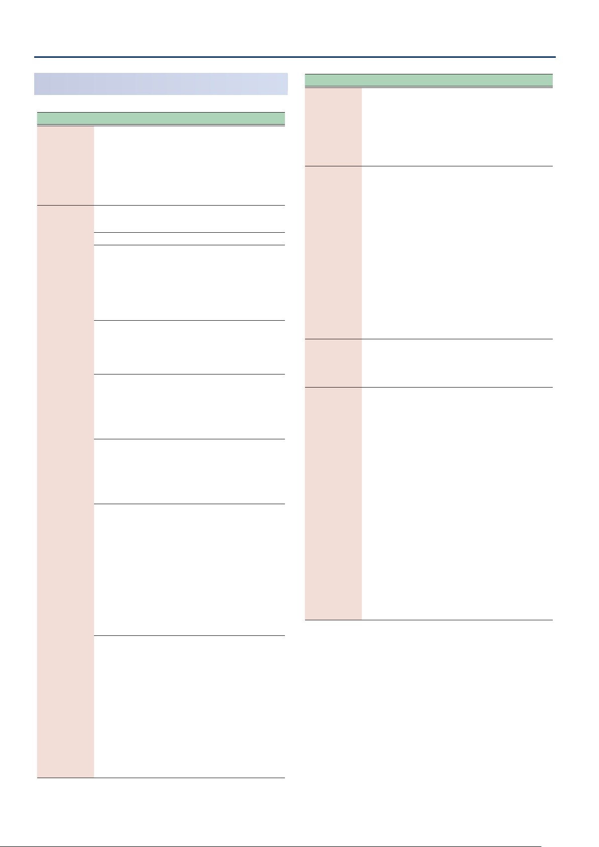
ZEN-Core Tone Parameters (Z-Core)
FILTER
Parameter Value Explanation
Selects the type of filter.
* TVF stands for Time Variant Filter, a
Filter Type T VF, VCF
Selects the type of TVF filter.
* If Filter Type is set to VCF, this will be LPF.
OFF No filter is used.
LPF
BPF
HPF
PKG
TVF Filter Type
(ZOOM)
LPF2
LPF3
filter that lets you specify in detail
how the frequency components of
the sound change over time.
If you select VCF, the polyphony
will be lower than if you select TVF.
Low Pass Filter. This cuts the frequencies
in the region above the cutoff frequency
(Cutoff Frequency).
high-frequency region, the sound
becomes more mellow. This is
the most common filter used in
synthesizers
Band Pass Filter. This leaves only the
frequencies in the region of the cutoff
frequency (Cutoff Frequency), and cuts
the rest. This can be useful when
creating distinctive sounds.
High Pass Filter. This cuts the
frequencies in the region below the
cutoff frequency
This is suitable for creating percussive
sounds emphasizing their higher
tones.
Peaking Filter. This emphasizes the
frequencies in the region of the cutoff
frequency
use this to create wah-wah effects
by employing an LFO to change the
cutoff frequency cyclically.
Low Pass Filter 2. Although frequency
components above the Cutoff
frequency
cut, the sensitivity of this filter is
half that of the LPF. This makes it
a comparatively warmer low pass
filter. This filter is good for use with
simulated instrument sounds such as
the acoustic piano.
* If you set “LPF2”, the setting for
the Resonance parameter will be
ignored (p. 29).
Low Pass Filter 3. Although frequency
components above the Cutoff
frequency
the sensitivity of this filter changes
according to the Cutoff frequency.
While this filter is also good for use
with simulated acoustic instrument
sounds, the nuance it exhibits differs
from that of the LPF2, even with the
same TVF Envelope settings.
* If you set “LPF3”, the setting for
the Resonance parameter will be
ignored (p. 29).
Since this cuts the
.
(Cutoff Frequency).
(Cutoff Frequency). You can
(Cutoff Frequency) are
(Cutoff Frequency) are cut,
Parameter Value Explanation
This parameter is effective when Filter
VCF1,
VCF Type
(ZOOM)
Filter Slope
(ZOOM)
HPF Cutoff 0–1023
Cutoff
(ZOOM)
J P,
MG,
P5
-12, -18, -24
[dB/Oct]
0–1023
Type is VCF.
Each setting simulates the operation
of an analog synthesizer’s LPF. In
particular, MG, JP, and P5 are types
that are suitable for reproducing
synthesizer sounds of the past.
This button selects the slope
(steepness) of the filter.
For VCF, you can choose -12, -18, or
-24.
For TVF, only -12 or -24 can be
selected.
If Filter Type is TVF, the following
limitations apply.
¹ You can specify only -12 dB or -24
dB. If you specify -18 dB, the sound
generator operates internally with
the -12 dB setting.
¹ If you specify -24 dB, the
polyphony will be lower than if you
specify -12 dB.
Specifies the cutoff frequency of the
-6 dB high-pass filter.
* This parameter is effective when
Filter Type is VCF.
Selects the frequency at which the
filter begins to have an effect on the
waveform’s frequency components.
With “LPF/LPF2/LPF3” selected for the
TVF Filter Type parameter, lower cutoff
frequency settings reduce a tone’s
upper harmonics for a more rounded,
warmer sound. Higher settings make
it sound brighter.
If “BPF” is selected for the Filter
Type, harmonic components will
change depending on the TVF Cutoff
Frequency setting. This can be useful
when creating distinctive sounds.
With “HPF” selected, higher Cutoff
Frequency settings will reduce lower
harmonics to emphasize just the
brighter components of the sound.
With “PKG” selected, the harmonics to
be emphasized will vary depending
on Cutoff Frequency setting.
2828
Page 29

ZEN-Core Tone Parameters (Z-Core)
-200
C4C3C2C1 C5 C6 C7
+50
+100
-100
o
-1
-2
+1
+2
Cuto frequency
(Octave)
Key
0
+200
-50
-200
1 2 3 4 5 6 7
LPF BPF HPF PKG
Level
Frequency
Cuto Frequency
High
Low
parameter value
1 2 3 4 5 6 7
0
C4C3C2C1 C5 C6 C7
-50
-100
+50
+100
Key
Time
Parameter Value Explanation
Use this parameter if you want the
cutoff frequency to change according
to the key that is pressed. Relative
to the cutoff frequency at the key
specified by Cutoff Keyfollow Base
Point, positive “+” values cause the
cutoff frequency to become higher as
you play above the reference key, and
negative “-” values cause the cutoff
Keyfollow
(ZOOM)
-200–+200
frequency to become lower.
Higher values will produce greater
change.
Selects one of the following seven
curves that determine how keyboard
playing dynamics
Cutoff Velocity
Curve
FIXED, 1–7
the cutoff frequency. Set this to
“FIXED” if you don’t want the Cutoff
frequency to be affected by the
keyboard velocity.
Use this parameter when changing
the cutoff frequency to be applied as
Cutoff Velocity
Sens
-100–+100
a result of changes in playing velocity.
Specify a positive “+” value if you want
the cutoff frequency to raise when
you play strongly, or a negative “-”
value if you want it to lower.
Cutoff
Keyfollow Base
Point
0–127
Specifies the reference key when
using Keyfollow to modify the cutoff
frequency. If this is 60, the C4 key
(middle C) is the reference key.
Emphasizes the portion of the sound
in the region of the cutoff frequency,
adding character to the sound.
Excessively high settings can produce
oscillation, causing the sound to
distort.
Resonance
(ZOOM)
0–1023
(velocity) influence
FILTER ENV
Parameter Value Explanation
Specifies the depth of the Filter
envelope. Higher settings increase
Env Depth
(ZOOM)
TVF Env Fine
Depth
-63–+63
-63–+63
Velocity Curve FIXED, 1–7
Velocity Sens -100–+100
T1 Velocity
Sens
T4 Velocity
Sens
-100–+100
-100–+100
Time Keyfollow -100–+100
the change produced by the Filter
envelope.
Negative (-) value will invert the shape
of the envelope.
Finely adjusts the depth of the filter
envelope.
Selects one of the following seven
types of curve by which keyboard
playing dynamics affect the depth of
the filter envelope.
If you don’t want keyboard playing
dynamics to affect the filter envelope
depth, specify “FIXED ”.
Specify this if you want keyboard
playing dynamics to affect the filter
envelope depth. Specify a positive “+”
value if you want the filter envelope to
apply more deeply as you play more
strongly, or a negative “-” value if you
want it to apply less deeply.
Specify this if you want keyboard
playing dynamics to affect Time 1 of
the filter envelope. If you want Time 1
to be speeded up for strongly played
notes, set this parameter to a positive
“+” value. If you want it to be slowed
down, set this to a negative “-” value.
Specify this if you want key release
velocity to affect Time 4 of the filter
envelope. If you want Time 4 to be
speeded up for quickly released
notes, set this parameter to a positive
(+) value. If you want it to be slowed
down, set this to a negative (-) value.
Specify this if you want the filter
envelope times (Time 2–Time 4) to
vary depending on the keyboard
position you play. Relative to the filter
envelope times at the C4 key
, positive “+” values shorten the
C)
times for notes played in the region
above C4, and negative “-” values
lengthen the times. Higher values will
produce greater change.
(middle
Resonance
Velocity Sens
Vibrato Cutoff
Sens
-100–+100
-100–+100
Use this parameter when changing
the resonance to be applied as a
result of changes in playing velocity.
Specify a positive “+” value if you want
resonance to increase when you play
strongly, or a negative “-” value if you
want it to decrease.
Specifies how the TVF Depth of LFO1
is affected by the zone parameter’s
VIBRATO: Zone Vibrato Depth.
FENV LFO
Trigger Switch
OFF, ON
If this is ON, the filter envelope is
cyclically retriggered by LFO1.
* This is effective only when
Envelope Mode is SUSTAIN.
2929
Page 30
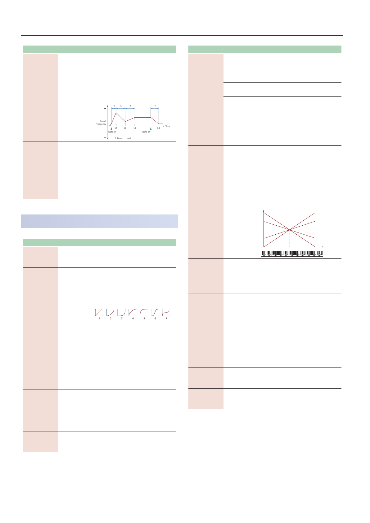
ZEN-Core Tone Parameters (Z-Core)
T1 T2 T3 T4
Note o
Cuto
Frequency
Time
Note on
T: Time L: Level
L3L0L2L1 L4
1 2 3 4 5 6 7
o
R
Pan
Parameter Value Explanation
Specify the filter envelope times (Time 1–
Time 4). Higher settings will lengthen the
time until the next cutoff frequency level
is reached. (For example, Time 2 is the time
T1/Attack,
T2,
T3/Decay,
0–1023
over which Level 1 will change to Level 2.)
* If ADSR Envelope Switch is ON, the
Time 2 has no effect.
T4/Release
(ZOOM)
Specify the filter envelope levels (Level 0–Level
L0,
L1,
L2,
L3/Sustain,
L4
(ZOOM)
0–1023
4).
Specify the amount of cutoff frequency
change at each point relative to the
reference cutoff frequency (the cutoff
frequency value specified in the Filter screen)
* If ADSR Envelope Switch is ON,
only Level 3 (Sustain) has an effect.
AMP
Parameter Value Explanation
Level
(ZOOM)
0–127
Velocity Curve FIXED, 1–7
Velocity Sens
(ZOOM)
-100–+100
Bias Level -100–+100
Bias Position 0–127
Sets the volume of the partial. This
setting is useful primarily for adjusting
the volume balance between partials.
Selects one of the following seven
curves that determine how keyboard
dynamics will affect the volume. Set
this to “FIXED” if you don’t want the
volume of the partial to be affected by
the keyboard velocity.
Set this when you want the volume
of the partial to change depending
on the force with which you press the
keys.
Set this to a positive (+) value to
have the changes in partial volume
increase the more forcefully the keys
are played; to make the partial play
more softly as you play harder, set this
to a negative (-) value.
Adjusts the angle of the volume
change that will occur in the selected
Bias Direction.
Higher values will produce greater
change. Negative (-) values will invert
the change direction.
Specifies the key relative to which the
volume will be modified. A setting of
64 is the C4 key
(middle C).
Parameter Value Explanation
Selects the direction in which change will occur
starting from the Bias Position.
The volume will be modified for the
keyboard area below the Bias Point.
The volume will be modified for the
keyboard area above the Bias Point.
The volume will be modified
symmetrically toward the left and
right of the Bias Point.
The volume changes linearly with the
bias point at the center.
Sets the pan of the partial. “L64” is far
left, “0” is center, and “63R” is far right.
Bias Direction
Pan
(ZOOM)
LOWER
UPPER
LOWER&
UPPER
ALL
L64–63R
Use this parameter if you want key
position to affect panning. Positive
(+) value will cause notes higher
than C4 key
.
increasingly further toward the right,
and negative (-) value will cause notes
(center C) to be panned
higher than C4 key (center C) to be
Pan Keyfollow
(ZOOM)
-100–+100
panned toward the left. Higher values
will produce greater change.
+100
+50
0
-50
L
C4C3C2C1 C5 C6 C7
-100
Key
Use this parameter when you want
Random Pan
Depth
0–63
the stereo location to change
randomly each time you press a key.
Higher values will produce a greater
amount of change.
This setting causes panning to be
alternated between left and right
each time a key is pressed. Higher
values will produce a greater amount
Alternate Pan
Depth
L63–63R
of change. “L” or “R” settings will
reverse the order in which the pan will
alternate between left and right.
For example if two partials are set to
“L” and “R” respectively, the panning of
the two tones will alternate each time
they are played.
Vibrato Level
Sens
-100–+100
Specifies how the zone parameter’s
VIBRATO: Zone Vibrato Depth affects
the Amp Depth of LFO1.
Adjusts the amount of width when
Stereo Width 0–100
outputting in stereo. This has no effect
when outputting in mono.
3030
Page 31

ZEN-Core Tone Parameters (Z-Core)
T1 T2 T3 T4
L3
L1
L2
Note o
Level
Time
Note on
T: Time L: Level
Time
AMP ENV
Parameter Value Explanation
Specify this if you want keyboard
dynamics to affect the AMP
T1 Velocity
Sens
T4 Velocity
Sens
AENV LFO
Trigger Switch
-100–100
-100–100
OFF, ON
T1/Attack,
T2,
T3/Decay,
0–1023
T4/Release
(ZOOM)
L1,
L2,
L3/Sustain
0–1023
(ZOOM)
Time Keyfollow -100–100
envelope’s Time 1. If you want Time 1
to be speeded up for strongly played
notes, set this parameter to a positive
(+) value. If you want it to be slowed
down, set this to a negative (-) value.
Specify this if you want key release
velocity to affect the AMP envelope’s
Time 4. If you want Time 4 to be
speeded up for quickly released
notes, set this parameter to a positive
(+) value. If you want it to be slowed
down, set this to a negative (-) value.
If this is ON, the amp envelope is
cyclically retriggered by LFO1.
* This is effective when Envelope
Mode is SUSTAIN.
Specify the AMP envelope times (Time
1–Time 4). Higher settings lengthen
the time until the next volume level
is reached. (For example, Time 2 is the
time over which Level 1 will change
to Level 2.)
* If ADSR Envelope Switch is ON, the
Time 2 has no effect.
Specify the AMP envelope levels
(Level 1–Level 3).
These specify the amount of change
at each point relative to the reference
volume
the Amp screen)
* If ADSR Envelope Switch is ON,
only Level 3 (Sustain) has an effect.
Specify this if you want keyboard
position to affect the AMP envelope’s
times (Time 2–Time 4). Relative to the
AMP envelope times at the C4 key
(middle C), positive (+) values cause the
times to shorten as you play higher on
the keyboard, and negative (-) values
cause the times to lengthen. Higher
values will produce greater change.
(the partial level value specified in
.
-100
-50
0
+50
+100
C4C3C2C1 C5 C6 C7
Key
LFO1 / LFO2
Parameter Value Explanation
Selects the waveform of the LFO.
SIN Sine wave
TRI Triangle wave
SAW-UP Sawtooth wave
SAW-DW Sawtooth wave
SQR Square wave
RND Random wave
Waveform
(LFO1, LFO2)
(ZOOM)
Tempo
Sync Sw
(LFO1, LFO2)
(ZOOM)
Rate Note
(LFO1, LFO2)
(ZOOM)
Rate
(LFO1, LFO2)
(ZOOM)
Offset (LFO1,
LFO2)
Rate Detune
(LFO1, LFO2)
Delay Time
(LFO1, LFO2)
(ZOOM)
TRP Trapezoidal wave
S&H
Sample & Hold wave (one time per
cycle, LFO value is changed)
CHS Chaos wave
Modified sine wave. The amplitude of
VSIN
a sine wave is randomly varied once
each cycle.
A waveform generated by the data
STEP
specified by LFO Step 1–16. This
produces stepped change with a fixed
pattern similar to a step modulator.
OFF
Set this ON if you want the LFO rate to
ON
synchronize with the tempo.
This is effective if Rate Sync is ON.
1/64T–4
Specifies the LFO rate in terms of a
note value.
This is effective if Rate Sync is OFF.
0–1023
Specifies the LFO rate without regard
to the tempo. Higher values produce a
faster LFO rate
Raises or lowers the LFO waveform
relative to the central value
cutoff frequency)
will move the waveform so that
-100–100
modulation will occur from the
central value upward. Negative (-)
value will move the waveform so that
modulation will occur from the central
value downward.
Subtly changes the LFO cycle speed
(Rate parameter) each time you press
0–127
a key. Higher values produce greater
change.
This parameter is invalid when Rate is
set to “note”.
Specifies the time elapsed before
the LFO effect is applied
continues)
0–1023
released)
* After referring to “How to Apply
the LFO” (p. 33), change the
setting until the desired effect is
achieved.
(negative polarity)
(a shorter cycle).
(pitch or
. Positive (+) value
(the effect
after the key is pressed (or
.
3131
Page 32

ZEN-Core Tone Parameters (Z-Core)
C4C3C2C1 C5 C6 C7
Key
Time
0
-50
-100
+50
+100
1 2
5 6
3 4
Parameter Value Explanation
Adjusts the value for the Delay Time
parameter depending on the key
position, relative to the C4 key
. To decrease the time that elapses
C)
before the LFO effect is applied
effect is continuous)
key that is pressed in the upper
registers, select a positive (+) value;
to increase the elapsed time, select
a negative (-) value. Higher values
Delay Time
Keyfollow
(LFO1, LFO2)
-100–100
will produce greater change. If you
do not want the elapsed time before
the LFO effect is applied (the effect is
continuous)
key pressed, set this to “0”.
ON-IN Specifies how the LFO will be applied.
Fade Mode
(LFO1, LFO2)
ON-OUT
OFF-IN
OFF-OUT
* After referring to “How to Apply
the LFO” (p. 33), change the
setting until the desired effect is
achieved.
Specifies the time over which the LFO
amplitude will reach the maximum
Fade Time
(LFO1, LFO2)
(ZOOM)
0–1023
(minimum).
* After referring to “How to Apply
the LFO” (p. 33), change the
setting until the desired effect is
achieved.
Key Trigger Sw
(LFO1, LFO2)
(ZOOM)
Pitch Depth
(LFO1, LFO2)
(ZOOM)
Filter Depth
(LFO1, LFO2)
(ZOOM)
Amp Depth
(LFO1, LFO2)
(ZOOM)
OFF, ON
-100–100
-100–100
-100–100
Specifies whether the LFO cycle will
be synchronized to begin when the
key is pressed
Specifies how deeply the LFO will
affect pitch.
* If OSC Type is other than VA, the
range is limited to -63–+63.
Specifies how deeply the LFO will
affect the cutoff frequency.
Specifies how deeply the LFO will
affect the volume.
Specifies how deeply the LFO will
affect the pan.
(center
(the
with each higher
to change according to the
(ON) or not (OFF).
Parameter Value Explanation
Specifies the LFO’s starting phase value when Key
Trigger is ON.
Phase Position
(LFO1, LFO2)
* This has no effect if Waveform is RND, S&H, or CHS.
0 1 cycle
1 1/4 cycle
2 1/2 cycle
3 3/4 cycle
STEP LFO1 / STEP LFO2
Parameter Value Explanation
Step Length
(LFO1, LFO2)
1–16
(ZOOM)
Step 1–16
(LFO1, LFO2)
-72–+72
(ZOOM)
Step Curve
1–16
(LFO1, LFO2)
0–36
(ZOOM)
Step curve types
Step Curve 0
This is effective if Waveform is STEP.
Specifies the step size that is looped.
This is effective if Waveform is STEP.
Specify the Depth value of each step.
If you want to specify this in pitch
scale degrees
are as follows.
Pitch Depth: 51, Step:
multiples of 6 … up to one
1
octave of change
Pitch Depth: 74, Step:
multiples of 3 … up to two
2
octaves of change
Pitch Depth: 89, Step:
multiples of 2 … up to three
3
octaves of change
* If OSC Type is not VA, the Pitch
Depth setting range is limited
to -63–+63, so only “1” above is
possible.
Specifies the type of curve at each
step.
Ø “Step curve types” (p. 32)
(100 cents), the settings
Pan Depth
(LFO1, LFO2)
(ZOOM)
3232
-63–+63
MEMO
Positive (+) and negative (-) value for the Depth
parameter result in differing kinds of change
in pitch and volume. For example, if you set
the Depth parameter to a positive (+) value
for one partial, and set another partial to the
same numerical value, but make it negative (-),
the modulation phase for the two partials will
be the reverse of each other. This allows you
to shift back and forth between two different
partials, or combine it with the Pan setting to
cyclically change the location of the sound
image.
Curve Type 1–6 (variations of square wave)
Page 33

ZEN-Core Tone Parameters (Z-Core)
7 8 9 10
11
15
12 13 14
16 17 18 19
20 21 22 23
24 25 26 27
28 29 30 31
32 33 34 35
36
Note on
high (more)
low (less)
Pitch
Cuto Frequency
Level
Pan
Delay
Time
Fade Time
Depth
high (more)
low (less)
Pitch
Cuto Frequency
Level
Pan
Note on
Delay Time
Fade Time
Depth
high (more)
low (less)
Delay
Time
Fade Time
Depth
Note
o
Note
on
Pitch
Cuto Frequency
Level
Pan
Note on
high (more)
low (less)
Delay
Time
Fade Time
Depth
Note o
Pitch
Cuto Frequency
Level
Pan
Curve Type 7–10 (variations of ascending saw)
Curve Type 11–15 (variations of descending saw)
Curve Type 16–19 (variations of ascending exponential)
Curve Type 20–23 (variations of descending exponential)
How to Apply the LFO
Apply the LFO gradually after the key is pressed
Fade Mode: ON-IN
Apply the LFO immediately when the key is pressed, and
then gradually begin to decrease the eect
Fade Mode: ON-OUT
Apply the LFO gradually after the key is released
Fade Mode: OFF-IN
Curve Type 24–27
(variations of ascending charging curve)
Curve Type 28–31
(variations of descending charging curve)
Curve Type 32–36 (other variations)
Apply the LFO from when the key is pressed until it is
released, and gradually begin to decrease the eect
when the key is released
Fade Mode: OFF-OUT
PARTIAL EQ
Parameter Value Explanation
Switch
(ZOOM)
Low Gain
(ZOOM)
Mid Gain
(ZOOM)
High Gain
(ZOOM)
OFF, ON
-24.0–+24.0
[dB]
-24.0–+24.0
[dB]
-24.0–+24.0
[dB]
Turns the equalizer on/off for each
partial.
Gain of the low range.
Gain of the middle range.
Gain of the high range
3333
Page 34

ZEN-Core Tone Parameters (Z-Core)
Parameter Value Explanation
Low Frequency
(ZOOM)
Mid Frequency
(ZOOM)
High
Frequency
(ZOOM)
Mid Q
(ZOOM)
20–16000 [Hz] Frequency of the low range.
20–16000 [Hz] Frequency of the middle range.
20–16000 [Hz] Frequency of the high range.
0.5–16.0
(0.1step)
Width of the middle range.
Set a higher value to narrow the range
to be affected.
OUTPUT
Parameter Value Explanation
Output Assign
(ZOOM)
Chorus Level
Send
Reverb Level
Send
DRY, MFX
0–127
0–127
Specifies how the sound of each
partial will be output.
Specifies the level of the signal sent to
the chorus for each partial.
Specifies the level of the signal sent to
the reverb for each partial.
CONTROL
Parameter Value Explanation
Increases the proportion by which
Soft EQ Sens 0–100
the EQ’s HighGain is lowered by the
amount of pedal.
With a setting of 0, this has no effect.
MATRIX CONTROL
Ordinarily, if you wanted to change partial parameters using an
external MIDI device, you would need to send System Exclusive
messages-MIDI messages designed exclusively for the FANTOM.
However, System Exclusive messages tend to be complicated, and the
amount of data that needs to be transmitted can get quite large.
For that reason, a number of the more typical of the FANTOM’s partial
parameters have been designed so they accept the use of Control
Change (or other) MIDI messages for the purpose of making changes
in their values. This provides you with a variety of means of changing
the way tones are played.
For example, you can use the Modulation Bar to change the LFO cycle
rate, or use the keyboard’s touch to open and close a lter.
The function which allows you use MIDI messages to make these
changes in realtime to the partial parameters is called the “Matrix
Control”.
Up to four Matrix Controls can be used in a single tone.
To use Matrix Control, you specify which MIDI message (Source)
controls which parameter (Destination) and how deeply (Sens:
sensitivity).
Parameter Value Explanation
If this is set to SUSTAIN, the Envelope Level 3 is
held from when the envelope Time 3 has elapsed
until note-off.
Envelope
Mode
Damper Free
Note
Damper Free
Decay Offset
Receive Bender OFF, ON
Receive
Expression
Receive Hold-1 OFF, ON
Redamper
Switch
NO-SUS,
SUSTAIN
OFF, 1–127
-100–+100
OFF, ON
OFF, ON
When note-off occurs, the envelope transitions
from the current value to the Time 4 segment
(release segment).
If this is set to NO-SUS, the envelope transitions
to the release segment after passing Time 3
regardless of the note-off timing, operating
according to the times specified by the envelope.
For notes above the specified note
number, the Envelope Mode operates
as NO-SUS.
Use this to simulate the undamped
region of a piano sound.
Specifies a fine adjustment to the
time over which the sound decays
when the Damper Free Note effect is
applied.
Specifies for each partial whether
MIDI pitch bend messages are
(ON) or not received (OFF).
received
Specifies for each partial whether
MIDI expression messages are
(ON) or not received (OFF).
received
Specifies for each partial whether
MIDI hold 1 messages are received
(ON) or not received (OFF).
If Redamper Switch is ON, you can
perform the Half Damper operations
used for piano sounds.
However, the following conditions
must be satisfied in order to use this
operation.
Envelope Mo de is NO-SUS
¹
¹ Amp Envelope ’s Level 1 and 2 are 1 or greate r
¹ Amp Envelope ’s Times are Time 3 > Ti me4
Parameter Value Explanation
Sets the MIDI message used to change the partial
parameter with the Matrix Control.
OFF Matrix control will not be used.
Source 1–4
(Matrix Control
1–4)
(ZOOM)
CC01–31,
CC33–95
BEND Pitch bend
AFT Aftertouch
SYS-CTRL1–4
VELOCITY Velocity
KEYFOLLOW Keyfollow (keyboard position with C4 as 0)
TEMPO
LFO1, LFO2
PIT-ENV Pitch envelope
FLT-ENV Filter envelope
AMP-ENV Amp envelope
Controller numbers 1–31, 33–95
MIDI messages assigned by the
SYSTEM parameters SYS-CTRL 1–4
(pressure you press a key with)
Tempo specified by the tempo assign
source
LFO 1
LFO 2
3434
Page 35

ZEN-Core Tone Parameters (Z-Core)
Parameter Value Explanation
* Velocity and Keyfollow correspond to Note
messages.
* Although there are no MIDI messages for LFO 1
through AMP Envelope, they can be used as Matrix
Control. In this case, you can change the partial
settings in realtime by playing tones.
* If you want to use common controllers for the entire
FANTOM, select “SYS-CTRL1”–”SYS-CTRL4”. MIDI
messages used as System Control 1–4 are set with
the System Control Source1–4. For details, refer to
“Reference Manual”
(PDF).
NOTE
Source 1–4
(Matrix Control
1–4)
(ZOOM)
Destination
1–4
(MATRIX CONTROL
1–4)
(ZOOM)
¹ There are parameters that determine whether or
not Pitch Bend, Controller Number 11 (Expression)
and Controller Number 64 (Hold 1) are received (p.
34). When these settings are “ON”, and the MIDI
messages are received, then when any change is
made in the settings of the desired parameter, the
Pitch Bend, Expression, and Hold 1 settings also
change simultaneously. If you want to change the
targeted parameters only, then set these to “OFF”.
¹ There are parameters that let you specify whether
specific MIDI messages will be received for each
zone in a scene (p. 16). When a tone with Matrix
Control settings is assigned to a zone, confirm that
any MIDI messages used for the Matrix Control
will be received. If the FANTOM is set up such that
reception of MIDI messages is disabled, then the
Matrix Control will not function.
Selects the partial parameter that is to be controlled
when using the Matrix Control. The following
parameters can be controlled.
When not controlling parameters with the Matrix
Control, set this to “OFF”.
Up to four parameters can be specified for each Matrix
Control, and controlled simultaneously.
OFF Matrix control will not be used.
PITCH Changes the pitch.
CUTOFF Changes the cutoff frequency.
Emphasizes the overtones in the
RESONANCE
LEVEL Changes the volume level.
PAN Changes the pan.
CHO Changes the amount of chorus.
REV Changes the amount of reverb.
PIT-LFO1
PIT-LFO2
FLT-LFO1
FLT-LFO2
AMP-LFO1
AMP-LFO2
PAN-LFO1
PAN-LFO2
LFO1-RATE Changes the speed of the LFO cycles.
LFO2-RATE
PIT-ATK
PIT-DCY
region of the cutoff frequency, adding
character to the sound.
Changes the vibrato depth.
Changes the wah depth.
Changes the tremolo depth.
Changes the effect that the LFO will
have on pan.
The speed will not change if LFO Rate
is set to “note”.
Changes the Time 1 of the pitch
envelope.
Changes the Time 2 and Env Time 3 of
the pitch envelope.
Parameter Value Explanation
Changes the Time 4 of the pitch
envelope.
Changes the Time 1 of the FLT
envelope.
Changes the Time 2 and Env Time 3 of
the FLT envelope.
Changes the Time 4 of the FLT
envelope.
Changes the Time 1 of the AMP
envelope.
Changes the Time 2 and Env Time 3 of
the AMP envelope.
Changes the Time 4 of the AMP
envelope.
If the Matrix Control is used to split
partials, set the PMT Velocity Control
(p. 24) to “OFF”.
¹ If the Matrix Control is used to split
partials, we recommend setting the
Sens (p. 36) to “+63”. Selecting a
lower value may prevent switching
of the partials. Furthermore, if you
want to reverse the effect, set the
value to “-63”.
¹ If you want to use matrix control to
switch smoothly between partials,
use the Velocity Fade Lower and
Velocity Fade Upper (p. 24). The
higher the values set, the smoother
the switch is between the partials.
Changing the depth of frequency
modulation produced by FXM
Applies a change to MFX CONTROL
1–4 Source. If this is specified for more
than one partial, the result will be the
summed values.
This setting is valid only for the carrier
(Partial 1 or 3), and applies
partial
change to the CrossMod1-2Depth or
CrossMod3-4Depth.
Waveform is STEP; it specifies the step
position. In this case, the Sens value
is ignored.
This is effective if OSC Type is
SuperSAW; it applies change to SuperSAW Detune.
Changes the depth of the Pitch
envelope.
Changes the depth of the Filter
envelope.
Changes the depth of the AMP
envelope.
This is effective when Structure 1-2
(3-4) is XMOD2; it applies change to
XMOD2 1-2 (3-4) Depth.
You can select OSC Attenuator as the
Destination.
Destination
1–4
(MATRIX CONTROL
1–4)
(ZOOM)
PIT-REL
FLT-ATK
FLT-DCY
FLT-REL
AMP-ATK
AMP-DCY
AMP-REL
PMT
FXM
MFX-CTRL1
MFX-CTRL2
MFX-CTRL3
MFX-CTRL4
PW Applies change to PW.
PWM Applies change to PWM.
FAT Applies change to FAT.
XMOD
LFO1-STEP This is valid if the LFO1/LFO2
LFO2-STEP
SSAW-DETN
PIT-DEPTH
FLT-DEPTH
AMP-DEPTH
XMOD2
ATT
3535
Page 36

ZEN-Core Tone Parameters (Z-Core)
Parameter Value Explanation
This is effective if Structure is RING.
In the case of Partial 1: Changes the
RING OSC 1 LEVEL of STRUCTURE.
In the case of Partial 2: This setting
has no effect.
In the case of Partial 3: Changes the
RING OSC 3 LEVEL of STRUCTURE.
In the case of Partial 4: This setting
has no effect.
This is effective if Structure is RING.
In the case of Partial 1: Changes the
RING OSC 2 LEVEL of STRUCTURE.
In the case of Partial 2: This setting
has no effect.
In the case of Partial 3: Changes the
RING OSC 4 LEVEL of STRUCTURE.
In the case of Partial 4: This setting
has no effect.
This is effective when Structure is
XMOD or XMOD2.
In the case of Partial 1: Changes the
XMOD OSC 1 LEVEL of STRUCTURE.
In the case of Partial 2: This setting
has no effect.
In the case of Partial 3: Changes the
XMOD OSC 3 LEVEL of STRUCTURE.
In the case of Partial 4: This setting
has no effect.
This is effective when Structure is
XMOD or XMOD2.
In the case of Partial 1: Changes the
XMOD OSC 2 LEVEL of STRUCTURE.
In the case of Partial 2: This setting
has no effect.
In the case of Partial 3: Changes the
XMOD OSC 4 LEVEL of STRUCTURE.
In the case of Partial 4: This setting
has no effect.
Specify the effective depth of the
matrix controls.
To make an increase in the currently
selected value (to get higher values,
move to the right, increase rates, and
so on), select a positive (+) value;
to make a decrease in the currently
selected value (to get lower values,
move to the left, decrease rates, and
so on), select a negative (-) value.
For either positive or negative value,
greater absolute values will allow
greater amounts of change.
Set this to “0” if you don’t want to
apply the effect.
Destination
1–4
(MATRIX CONTROL
1–4)
(ZOOM)
Sens 1–4
(MATRIX CONTROL
1–4)
(ZOOM)
RINGOSC1-LEV
RINGOSC2-LEV
XMODOSC1-LEV
XMODOSC2-LEV
-63–+63
Parameter Value Explanation
Edit the parameters for the selected MFX. The available
MFX
Parameters
MFX Chorus
Send Level
MFX Reverb
Send Level
parameters differ depending on the type of the effects
you selected in MFX Type.
Ø “MFX/IFX Parameters” (p. 56)
Adjusts the amount of chorus.
0–127
0–127
If you don’t want to add the chorus
effect, set it to 0.
Adjusts the amount of reverb.
If you don’t want to add the reverb
effect, set it to 0.
MFX CTRL
Parameter Value Explanation
Specifies the MIDI message that will control the
corresponding MFX CONTROL parameter.
OFF MFX CONTROL will not be used.
Control 1–4
Source
Control 1–4
Destination
Control 1–4
Sens
Controlling a MFX via MIDI (MFX CONTROL)
You can use MIDI messages such as control change messages to control the
principal MFX parameters. This capability is called “MFX CONTROL (multieffects control)”.
The editable parameters are pre-determined according to the MFX type.
You can specify up to four parameters for multi-effect control.
To use MFX CONTROL, you’ll need to specify which MIDI message
will affect which parameter (Destination), and how greatly (Sens).
CC01–31 Controller number 1–31
CC33–95 Controller number 33–95
BEND Pitch bend
AFT Aftertouch
SYS-CTRL1–4
-63–+63
Use the controller that is assigned by
the System Control Source 1–4.
Specifies the multi-effect parameters
that are controlled by MFX CONTROL.
The multi-effects parameters available
for control will depend on the multieffects type.
Specifies the depth of MFX CONTROL.
Specify a positive (+) value if you want
to change the value of the assigned
destination in a positive direction
(larger, toward the right, faster,
etc.), or specify a negative (-) value
if you want to change the value in a
negative direction (smaller, toward
the left, slower, etc.). Larger values will
allow a greater amount of control.
(Source)
MFX
Parameter Value Explanation
MFX Type Selects the MFX type.
MFX Switch OFF, ON Switches the MFX on/off.
3636
Page 37

Drum Kit Tone Parameters (Drum)
1. Select the zone to which the tone is assigned.
2. Press the [MENU] button.
The MENU screen appears.
3. Touch <TONE EDIT>.
The TONE EDIT screen appears.
4. Touch the tab of the section that you want to edit.
5. Move the cursor to the desired parameter, and
edit the value.
NOTE
The edited parameters are temporary. They are lost when you turn o
the power. If you want to keep your changes, you must save the tone.
KIT COMMON
Parameter Value Explanation
(Name) Tone name
Level 0–127
Adjusts the overall volume of the
tone.
KIT MFX
Parameter Value Explanation
Type Selects the MFX type.
Switch OFF, ON Switches the MFX on/off.
Edit the parameters for the selected MFX. The available
MFX
Parameters
Chorus Send
Level
Reverb Send
Level
parameters differ depending on the type of the effects
you selected in MFX Type.
Ø “MFX/IFX Parameters” (p. 56)
Adjusts the amount of chorus.
0–127
0–127
If you don’t want to add the chorus
effect, set it to 0.
Adjusts the amount of reverb.
If you don’t want to add the reverb
effect, set it to 0.
Parameter Value Explanation
Specifies the multi-effect parameters
Control 1–4
Destination
Control 1–4
Sens
-63–+63
that are controlled by MFX Control.
The multi-effects parameters available
for control will depend on the multieffects type.
Specifies the depth of MFX CONTROL.
Specify a positive (+) value if you want
to change the value of the assigned
destination in a positive direction
(larger, toward the right, faster,
etc.), or specify a negative (-) value
if you want to change the value in a
negative direction (smaller, toward
the left, slower, etc.). Larger values will
allow a greater amount of control.
KIT COMP1–6
* KIT COMP can be used only for the zone specified by Drum Kit Comp
Zone.
Parameter Value Explanation
Switch OFF, ON Compressor on/off
Time from when the input exceeds
Attack Time 0.1–100ms
Release Time 10–1000ms
Threshold -60–0 [dB] Level at which compression is applied
Ratio 1:1–inf:1 Compression ratio
Knee 0–30 [dB]
Output Gain -24–+24 [dB] Adjusts the output gain.
Output Assign
DRY, MFX,
MAIN, SUB
the threshold until compression
begins
Time from when the input falls below
the threshold until compression is
turned off
This is a function that smooths the
onset of compression from the
uncompressed state; it gradually
applies compression starting earlier
than Threshold. Higher values
produce a smoother transition.
Specifies the compressor output
destination.
KEY PARAM
KIT MFX CTRL
Parameter Value Explanation
Specifies the MIDI message that will control the
corresponding MFX CONTROL parameter.
OFF MFX CONTROL will not be used.
Control 1–4
Source
CC01–31 Controller number 1–31
CC33–95 Controller number 33–95
BEND Pitch bend
AFT Aftertouch
SYS-CTRL1–4
Use the controller that is assigned by
the System Control Source 1–4.
Parameter Value Explanation
21
Current Note
Inst Number 000–
Inst Group ID A, B Selects the Inst group ID.
Inst 000– Selects the Inst.
Level 0–127 Adjusts the volume of the key.
Pan L64–0–63R Adjusts the stereo location of the key.
Chorus Send
Level
Reverb Send
Level
(A0)–108
(C8)
0–127
0–127
Selects the key.
Selects the Inst to be assigned to the
key.
Adjusts the amount of chorus for each key.
Adjusts the amount of reverb for each key.
3737
Page 38

Drum Kit Tone Parameters (Drum)
Parameter Value Explanation
On an actual acoustic drum set, an
open hi-hat and a closed hi-hat sound
can never occur simultaneously.
To reproduce the reality of this
situation, you can set up a Mute
Mute Group OFF, 1–31
Output Assign
Key Offset -24–+24 Shifts the pitch in units of a semitone.
Fine Tune
Offset
Cutoff Offset -100–+100
Resonance
Offset
Attack Time
Offset
Decay Time
Offset
Release Time
Offset
DRY, MFX,
COMP1–6
-50–+50 [cent]
-100–+100
-100–+100
-100–+100
-100–+100
Group.
The Mute Group function allows you
to designate two or more keys that are
not allowed to sound simultaneously.
Up to 31 Mute Groups can be used.
Keys that are not belong to any such
group should be set to “OFF”.
Specifies the output destination for
each key.
Finely adjusts the pitch in units of one
cent.
Adjusts how far the filter is open.
Increasing this value makes the sound
brighter, and decreasing it makes the
sound darker.
Emphasizes the portion of the sound
in the region of the cutoff frequency,
adding character to the sound.
Excessively high settings can produce
oscillation, causing the sound to
distort.
Increasing this value strengthens the
character, and decreasing it weakens
the character.
Adjusts the time over which the sound
reaches its maximum volume after you press
the key.
Larger settings of this value make the
attack gentler, and smaller settings
make the attack sharper.
Adjusts the time over which the
volume decreases from its maximum
value.
Larger settings of this value make the
decay longer, and smaller settings
make the decay shorter.
The time it takes after the key is
released for a sound to become
inaudible.
If Envelope Mode is NO-SUS, this
is the time until the sounded note
becomes inaudible.
Larger settings of this value make the
sound linger, and smaller settings
make the sound end more sharply.
KEY EQ
Parameter Value Explanation
21
Current Note
Inst Number 000–
EQ Switch OFF, ON
Low Gain
Mid Gain
High Gain
Low Frequency 20–16000 [Hz] Frequency of the low range.
Mid Frequency 20–16000 [Hz] Frequency of the middle range.
High
Frequency
Mid Q
(A0)–108
(C8)
-24.0–+24.0
[dB]
-24.0–+24.0
[dB]
-24.0–+24.0
[dB]
20–16000 [Hz] Frequency of the high range.
0.5–16.0
(0.1step)
Selects the key.
Selects the Inst to be assigned to the
key.
Turns the equalizer on/off for each
key.
Gain of the low range.
Gain of the middle range.
Gain of the high range
Width of the middle range.
Set a higher value to narrow the range
to be affected.
INST COMMON
Parameter Value Explanation
21
Current Note
Inst Number 000–
Category 00–21 Selects the Inst’s category.
Level 0–127 Adjusts the volume of the Inst.
Source Key 0–127
Fine Tune -50–+50 [cent]
Random Pitch
Depth
Assign Type MULTI, SINGLE
(A0)–108
(C8)
0–1200 [cent]
Selects the key.
Selects the Inst to be assigned to the
key.
Specifies the pitch in semitone steps
relative to 60
instrument)
Adjusts the pitch of the sound up or
down in 1-cent steps (+/-50 cents).
Specifies the width in which the pitch
is randomly changed each time the
note is sounded. If you do not want
the pitch to change randomly, set this
to “0”.
Sets the way sounds are played when
the same key is pressed a number of
times.
MULTI: Layer the sound of the
same keys. Even with continuous
sounds where the sound plays for an
extended time, such as with crash
cymbals, the sounds are layered,
without previously played sounds
being eliminated.
SINGLE: Only one sound can be
played at a time when the same
key is pressed. With continuous
sounds where the sound plays for an
extended time, the previous sound is
stopped when the following sound is
played.
(the original pitch of the
.
3838
Page 39

Drum Kit Tone Parameters (Drum)
Parameter Value Explanation
When a loop waveform is selected,
the sound will normally continue as
long as the key is pressed. If you want
Envelope
Mode
NO-SUS,
SUSTAIN
the sound to decay naturally even if
the key remains pressed, set this to
“NO-SUS”.
* If a one-shot type Wave is selected,
it will not sustain even if this
parameter is set to “SUSTAIN”.
Determines whether a different wave
is played
(ON) or not (OFF) depending
on the force with which the key is
WMT Velocity
Control
OFF, ON,
RANDOM
played.
When set to “RANDOM”, the tone’s
constituent wave will sound
randomly, regardless of any velocity
messages.
Matches the wave playback to the
Wave Tempo
Sync
OFF, ON
tempo. This only works with waves
for which the BPM is indicated. When
this function is enabled, parameters
related to pitch and FXM are disabled.
INST WAVE
Parameter Value Explanation
21
Current Note
Inst Number 000–
Wave Group INT, EXP, SAMP
Wave Bank A, B, C, D Specifies the bank of the Wave Group.
Wave
Number L
Wave
Number R
Wave Gain -18–+12 [dB]
Wave FXM Sw OFF, ON
(A0)–108
(C8)
Selects the key.
Selects the Inst to be assigned to the
key.
Sets the wave group that plays when
OSC Type is “PCM”.
INT: Uses the built-in waves.
EXP: Uses the expansion waves.
SAMP: Uses the samples as waves.
Specifies the wave number within the
group specified by Wave Group.
If using mono, specify only the left
side
(L). If using stereo, specify the
right side (R) as well.
If using mono, specify only Wave
Number L and leave Wave Number R
at 0: OFF.
If you specify only Wave Number R, no
sound is heard.
Specifies the gain
(amplitude) of the
waveform.
The value will change in 6 dB
(decibel)
steps.
Each 6 dB increase doubles the gain.
This sets whether FXM will be used
(ON) or not (OFF).
* FXM
(Frequency Cross Modulation)
uses a specified waveform to
apply frequency modulation to
the currently selected waveform,
creating complex overtones. This is
useful for creating dramatic sounds
or sound effects.
Parameter Value Explanation
Specifies how FXM will perform
Wave FXM
Color
1–4
frequency modulation. Higher
settings result in a grainier sound,
while lower settings result in a more
metallic sound.
Wave FXM
Depth
0–16
Specifies the depth of the modulation
produced by FXM.
Adjusts the pitch of each wave’s
sound up or down in semitone steps
Wave Coarse
Tune
-48–48
(+/-4 octaves).
MEMO
The Coarse Tune of the entire drum
partial is set by the Source Key (p. 38).
Adjusts the pitch of each Wave’s
sound up or down in 1-cent steps
Wave Fine
Tune
-50–+50
(+/-50 cents).
* One cent is 1/100th of a semitone.
MEMO
The Fine Tune of the entire drum partial is
set by the Fine Tune (p. 38).
Adjusts the level of each Wave.
MEMO
Wave Level 0–127
The volume level of each drum partial
is set with the Partial Level; the volume
levels of the entire drum kit is set with the
Level (p. 38).
This specifies the pan of the
Wave Pan L64–63R
waveform.
“L64” is far left, “0” is center, and “63R”
is far right.
Use this setting to cause the
waveform’s panning to change
Wave Random
Pan
OFF, ON
randomly each time a key is pressed
(ON) or not (OFF).
* The range of the panning change
is set by the Random Pan Depth
(p. 30).
Use this parameter when you want
Random Pan
Depth
0–63
the stereo location to change
randomly each time you press a key.
Higher values will produce a greater
amount of change.
This setting causes panning of the
waveform to be alternated between
left and right each time a key is
pressed.
Wave Alternate
Pan
OFF, ON, REVS
Set this to “ON” to pan the Wave
according to the Alternate Pan Depth
settings, or to “REVS” when you want
the panning reversed.
If you do not want the panning to
change each time a key is pressed, set
this to “OFF”.
This setting causes panning to be
alternated between left and right
each time a key is pressed. Higher
values will produce a greater amount
Alternate Pan
Depth
L64–63R
of change. “L” or “R” settings will
reverse the order in which the pan will
alternate between left and right.
For example, if the INST WAVE setting
Wave Alter Pan Sw is ON or REVS for
the two waves, the pan will alternate
each time the key is pressed.
3939
Page 40

Drum Kit Tone Parameters (Drum)
Note on
Note o
Delay time
Note on
No sound
played
Note o
Delay time
Note on
Note o
Delay time
Note on
Range Lower
Range Upper
Fade Lower
Fade Upper
Level
Velocity
INST WMT
Parameter Value Explanation
21
Current Note
Inst Number 000–
Wave Delay
Mode
(A0)–108
(C8)
Selects the key.
Selects the Inst to be assigned to the
key.
Wave delay
This produces a time delay between the moment a
key is pressed
(or released), and the moment the Wave
actually begins to sound. You can also make settings
that shift the timing at which each Wave is sounded.
This differs from the Delay in the internal effects, in
that by changing the sound qualities of the delayed
Wave and changing the pitch for each Wave, you can
also perform arpeggio-like passages just by pressing
one key.
You can also synchronize the Wave delay time to the
tempo of the external MIDI sequencer.
The Wave begins to play after the
time specified in the Wave Delay Time
parameter has elapsed.
NORMAL
No Partial Delay
Parameter Value Explanation
Rather than being played while the
key is pressed, the Wave begins to
play once the period of time specified
in the Wave Delay Time parameter has
elapsed after release of the key. Here,
however, changes in the TVA Envelope
Wave Delay
Mode
KEYOFF-DECAY
begin while the key is pressed, which
in many cases means that only the
sound from the release portion of the
envelope is heard.
Wave Delay
Time Sync
Wave Delay
Time (note)
Wave Delay
Time
OFF, ON
1/64T–2
0–1023
Set this ON if you want the Wave delay
time to synchronize with the tempo.
This is available when Wave Delay
Time Sync is ON. It specifies the delay
time in terms of a note value.
This is available when Wave Delay
Time Sync is OFF. It specifies the delay
time without regard to the tempo.
Wave Delay
Mode
HOLD
KEYOFFNORMAL
Delay time
Note o
Although the Wave begins to play
after the time specified in the Wave
Delay Time parameter has elapsed,
if the key is released before the time
specified in the Wave Delay Time
parameter has elapsed, the Wave is
not played.
Rather than being played while the
key is pressed, the Wave begins to
play once the period of time specified
in the Wave Delay Time parameter has
elapsed after release of the key.
This is effective in situations such as
when simulating noises from guitars
and other instruments.
Parameter Value Explanation
Velocity Range
Low
1–127
Specifies the lower limit
upper limit (Upper) of the velocities
that will sound the Wave.
Velocity
Range Up
1–127
Make these settings when you want
to play different Waves depending on
your keyboard dynamics.
Specifies the degree to which the
Velocity Fade
Low
0–127
Wave is sounded by notes played
more softly than Velocity Range Low.
If you don’t want the tone to sound at
all, set this parameter to “0”.
Specifies the degree to which the
Velocity
Fade Up
0–127
Wave is sounded by notes played
more strongly than Velocity Range Up.
If you don’t want the tone to sound at
all, set this parameter to “0”.
PITCH ENV
(Lower) and
4040
Parameter Value Explanation
21
Current Note
Inst Number 000–
(A0)–108
(C8)
Selects the key.
Selects the Inst to be assigned to the
key.
Adjusts the effect of the Pitch
Envelope. Higher settings will cause
Env Depth -100–+100
the pitch envelope to produce greater
change. Negative (-) value will invert
the shape of the envelope.
Page 41

Drum Kit Tone Parameters (Drum)
1 2 3 4 5 6 7
T1 T2 T3 T4
L1
L0
Pitch
Note on
T:Time L:Level
L3
L2
Note o
Time
L4
Parameter Value Explanation
You can select from one of seven
curves, which affect how the pitch
changes according to how hard you
Pitch Env
Velocity Curve
0–7
play the keys. If you don’t want the
pitch to change according to how
hard you play the keys, set this to
“FIXED”.
Keyboard playing dynamics can
be used to control the depth of
the pitch envelope. If you want the
Env Velocity
Sens
-100–+100
pitch envelope to have more effect
for strongly played notes, set this
parameter to a positive (+) value. If
you want the pitch envelope to have
less effect for strongly played notes,
set this to a negative (-) value.
This allows keyboard dynamics
to affect the Time 1 of the Pitch
envelope.
Env Time 1
Velocity Sens
-100–+100
If you want Time 1 to be speeded
up for strongly played notes, set this
parameter to a positive (+) value. If
you want it to be slowed down, set
this to a negative (-) value.
Use this parameter when you want
key release speed to affect the Time 4
value of the pitch envelope.
Env Time 4
Velocity Sens
-100–+100
If you want Time 4 to be speeded up
for quickly released notes, set this
parameter to a positive (+) value. If
you want it to be slowed down, set
this to a negative (-) value.
Specify the pitch envelope times
(Time 1–Time 4).
Higher settings will result in a longer
time until the next pitch is reached.
(For example, Time 2 is the time over
which the pitch changes from Level 1
Env Time 1–4 0–1023
to Level 2.)
Specify the pitch envelope levels
(Level 0–Level 4).
It determines how much the pitch
changes from the reference pitch
Env Level 0–4 -511–+511
value set with Coarse Tune or Fine Tune on
the Pitch screen)
Positive (+) value will cause the pitch
to be higher than the standard pitch,
and negative (-) value will cause it to
be lower.
at each point.
(the
INST FILTER
Parameter Value Explanation
21
Current Note
Inst Number 000–
Filter Type
(A0)–108
(C8)
Selects the key.
Selects the Inst to be assigned to the
key.
Selects the type of filter.
OFF No filter is used.
Low Pass Filter. This cuts the
frequencies in the region above the
cutoff frequency
LPF
Since this cuts the high-frequency
region, the sound becomes more
mellow. This is the most common filter
used in synthesizers.
Band Pass Filter. This leaves only the
frequencies in the region of the cutoff
BPF
frequency
the rest. This can be useful when
creating distinctive sounds.
High Pass Filter. This cuts the
frequencies in the region below the
HPF
cutoff frequency
This is suitable for creating percussive
sounds emphasizing their higher
tones.
Peaking Filter. This emphasizes the
frequencies in the region of the cutoff
PKG
frequency
be used to portray the resonance
peak of a drum.
Low Pass Filter 2. Although frequency
components above the Cutoff
frequency
cut, the sensitivity of this filter is
half that of the LPF. This makes it
LPF2
a comparatively warmer low pass
filter. This filter is good for use with
simulated instrument sounds such as
the acoustic piano.
* If you set “LPF2”, the setting for
the Resonance parameter will be
ignored (p. 42).
Low Pass Filter 3. Although frequency
components above the Cutoff
frequency
the sensitivity of this filter changes
according to the Cutoff frequency.
While this filter is also good for use
LPF3
with simulated acoustic instrument
sounds, the nuance it exhibits differs
from that of the LPF2, even with the
same TVF Envelope settings.
* If you set “LPF3”, the setting for
the Resonance parameter will be
ignored (p. 42).
(Cutoff Frequency).
(Cutoff Frequency), and cuts
(Cutoff Frequency).
(Cutoff Frequency). This can
(Cutoff Frequency) are
(Cutoff Frequency) are cut,
4141
Page 42

Drum Kit Tone Parameters (Drum)
1 2 3 4 5 6 7
LPF BPF HPF PKG
Level
Frequency
Cuto Frequency
High
Low
parameter value
1 2 3 4 5 6 7
T1 T2 T3 T4
Note o
Cuto
Frequency
Time
Note on
T: Time L: Level
L3L0L2L1 L4
Parameter Value Explanation
Selects the frequency at which the
filter begins to have an effect on the
waveform’s frequency components.
With “LPF/LPF2/LPF3” selected for the
Filter Type parameter, lower cutoff
frequency settings reduce a tone’s
upper harmonics for a more rounded,
warmer sound. Higher settings make
it sound brighter.
Cutoff
Frequency
0–1023
If “BPF” is selected for the Filter
Type, harmonic components will
change depending on the TVF Cutoff
Frequency setting. This can be useful
when creating distinctive sounds.
With “HPF” selected, higher Cutoff
Frequency settings will reduce lower
harmonics to emphasize just the
brighter components of the sound.
With “PKG” selected, the harmonics to
be emphasized will vary depending
on Cutoff Frequency setting.
Selects one of the following seven
curves that determine how keyboard
playing dynamics
Cutoff Velocity
Curve
FIXED, 1–7
the cutoff frequency. Set this to
“FIXED” if you don’t want the Cutoff
frequency to be affected by the
keyboard velocity.
Use this parameter when changing
the cutoff frequency to be applied as
Cutoff Velocity
Sens
-100–+100
a result of changes in playing velocity.
Specify a positive “+” value if you want
the cutoff frequency to raise when
you play strongly, or a negative “-”
value if you want it to lower.
Emphasizes the portion of the sound
in the region of the cutoff frequency,
adding character to the sound.
Excessively high settings can produce
oscillation, causing the sound to
distort.
Resonance 0–1023
(velocity) influence
FILTER ENV
Parameter Value Explanation
21
Current Note
Inst Number 000–
Env Depth -63–+63
Env Velocity
Curve
Env Velocity
Sens
Env Time 1
Velocity Sens
Env Time 4
Velocity Sens
Env Time 1–4 0–1023
(A0)–108
(C8)
FIXED, 1–7
-100–+100
-100–+100
-100–+100
Selects the key.
Selects the Inst to be assigned to the
key.
Specifies the depth of the Filter
envelope. Higher settings increase
the change produced by the Filter
envelope.
Negative (-) value will invert the shape
of the envelope.
Selects one of the following seven
types of curve by which keyboard
playing dynamics affect the depth of
the filter envelope.
If you don’t want keyboard playing
dynamics to affect the filter envelope
depth, specify “FIXED ”.
Specify this if you want keyboard
playing dynamics to affect the filter
envelope depth. Specify a positive “+”
value if you want the filter envelope to
apply more deeply as you play more
strongly, or a negative “-” value if you
want it to apply less deeply.
Specify this if you want keyboard
playing dynamics to affect Time 1 of
the filter envelope. If you want Time 1
to be speeded up for strongly played
notes, set this parameter to a positive
(+) value. If you want it to be slowed
down, set this to a negative (-) value.
Specify this if you want key release
velocity to affect Time 4 of the filter
envelope. If you want Time 4 to be
speeded up for quickly released
notes, set this parameter to a positive
(+) value. If you want it to be slowed
down, set this to a negative (-) value.
Specify the filter envelope times
(Time 1–Time 4). Higher settings
will lengthen the time until the next
cutoff frequency level is reached.
(For example, Time 2 is the time over
which Level 1 will change to Level 2.)
Resonance
Velocity Sens
4242
-100–+100
Use this parameter when changing
the resonance to be applied as a
result of changes in playing velocity.
Specify a positive “+” value if you want
resonance to increase when you play
strongly, or a negative “-” value if you
want it to decrease.
Specify the filter envelope levels
(Level 0–Level 4).
Specify the amount of cutoff
Env Level 0–4 0–1023
frequency change at each point
relative to the reference cutoff
frequency
specified in the Filter screen)
(the cutoff frequency value
.
Page 43

Drum Kit Tone Parameters (Drum)
1 2 3 4 5 6 7
T1 T2 T3 T4
L3
L1
L2
Note o
Level
Time
Note on
T: Time L: Level
INST AMP
Parameter Value Explanation
21
Current Note
Inst Number 000–
Level Velocity
Curve
Level Velocity
Sens
(A0)–108
(C8)
FIXED, 1–7
-100–+100
Selects the key.
Selects the Inst to be assigned to the
key.
Selects one of the following seven
curves that determine how keyboard
dynamics will affect the volume. Set
this to “FIXED” if you don’t want the
volume of the partial to be affected by
the keyboard velocity.
Set this when you want the volume
of the partial to change depending
on the force with which you press the
keys.
Set this to a positive (+) value to
have the changes in partial volume
increase the more forcefully the keys
are played; to make the partial play
more softly as you play harder, set this
to a negative (-) value.
Parameter Value Explanation
Specify the AMP envelope levels
(Level 1–Level 3).
These specify the amount of change
at each point relative to the reference
volume
(the partial level value specified in
Env Level 1–3 0–1023
the Amp screen)
.
AMP ENV
Parameter Value Explanation
21
Current Note
Inst Number 000–
Env Time 1
Velocity Sens
Env Time 4
Velocity Sens
Env Time 1–4 0–1023
(A0)–108
(C8)
-100–+100
-100–+100
Selects the key.
Selects the Inst to be assigned to the
key.
Specify this if you want keyboard
dynamics to affect the AMP
envelope’s Time 1. If you want Time 1
to be speeded up for strongly played
notes, set this parameter to a positive
(+) value. If you want it to be slowed
down, set this to a negative (-) value.
Specify this if you want key release
velocity to affect the AMP envelope’s
Time 4. If you want Time 4 to be
speeded up for quickly released
notes, set this parameter to a positive
(+) value. If you want it to be slowed
down, set this to a negative (-) value.
Specify the AMP envelope times (Time
1–Time 4). Higher settings lengthen
the time until the next volume level
is reached. (For example, Time 2 is the
time over which Level 1 will change
to Level 2.)
4343
Page 44

VTW Tone Parameter (VTW)
1. Select the zone 2.
You can select the VTW (Virtual Tone Wheel) type only for zone 2.
2. Press the [MENU] button.
The MENU screen appears.
3. Touch <TONE EDIT>.
The TONE EDIT screen appears.
4. Touch the tab of the section that you want to edit.
5. Move the cursor to the desired parameter, and
edit the value.
NOTE
The edited parameters are temporary. They are lost when you turn o
the power. If you want to keep your changes, you must save the tone.
COMMON
Parameter Value Explanation
Category 00–49 Tone category
Level 0–127 Overall level of the VTW tones
The tonewheel spins when this is set
to SPIN. The tonewheel stops spinning
Wheel Brake SPIN, STOP
Tone Wheel
Speed Up
OFF, ON
when this is set to STOP.
MEMO
When stopped, no sound is made. Switch
between STOP and SPIN to create unique
changes in the tone.
When this is ON, the tonewheel spins
faster, changing the pitch.
WHEEL
Parameter Value Explanation
Tonewheel types
1 (VINTAGE-1): A tonewheel used in
the tonewheel organs of the 1970’s.
Tone Wheel
Type
Leakage Level 0–63
Vibrato Chorus
Switch
Vibrato Chorus
Type
VINTAGE-1,
VINTAGE-2,
SOLID, CLEAN
OFF, ON Vibrato/chorus on/off
V-1, C-1, V-2,
C-2, V-3, C-3
2 (VINTAGE-2): A tonewheel used in
the tonewheel organs of the 1960’s.
3
(SOLID): A tonewheel that adds
harmonics to the low range of
VINTAGE-1 to emphasize the low end.
4
(CLEAN): A tonewheel without
leakage noise.
This specifies the amount of leakage
(distinctive noise produced by a
noise
tonewheel organ)
V-1: applies a slight vibrato effect.
V-2: applies a medium vibrato effect.
V-3: applies a strong vibrato effect.
C-1: applies a slight chorus effect.
C-2: applies a medium chorus effect.
C-3: applies a strong chorus effect.
.
Parameter Value Explanation
Percussion
Switch
Percussion
Harmonic
Percussion
Decay
Percussion
Volume
Percussion Soft
Level
Percussion
Norm Level
Percussion
Slow Time
Percussion Fast
Time
Percussion
Recharge Time
Percussion
H.Bar Level
Upper
Harmonic Bar
16’
Upper
Harmonic Bar
5-1/3’
Upper
Harmonic
Bar 8’
Upper
Harmonic
Bar 4’
Upper
Harmonic Bar
2-2/3’
Upper
Harmonic
Bar 2’
Upper
Harmonic Bar
1-3/5’
Upper
Harmonic Bar
1-1/3’
Upper
Harmonic
Bar 1’
Key On Click
Level
Key Off Click
Level
OFF, ON Percussion sound on/off
2ND: produces a percussion sound at
the same pitch as the 4’ harmonic bar.
2ND, 3RD
SLOW, FAST
NORM, SOFT
0–15
0–15
0–127
0–127
0–10 Percussion recharge time
0–127
0–8
0–8
0–8
0–8
0–8
0–8
0–8
0–8
0–8
0–63
0–63
3RD: produces a percussion sound at
the same pitch as the 2 2/3’ harmonic
bar.
SLOW: The percussion sound will
decay slowly, producing a softer
attack.
FAST: The percussion sound will
decay immediately, producing a
sharper attack.
NORM: The percussion will be at its
normal volume, and the sound of the
harmonic bars will be decreased.
SOFT: The percussion sound will be
decreased, and the harmonic bars will
be at their normal volume.
Volume of percussion sound when
PERCUSSION [SOFT] is on
Volume of percussion sound when
PERCUSSION [SOFT] is off
Volume of percussion sound when
PERCUSSION [SLOW] is on
Volume of percussion sound when
PERCUSSION [SLOW] is off
Volume of harmonic bars when
PERCUSSION [SOFT] is off
Sets the volume of each harmonic bar.
This specifies the level of the click
sound heard when you press a key.
This specifies the level of the click
sound heard when you release a key.
4444
Page 45

VTW Tone Parameter (VTW)
Parameter Value Explanation
Sets the expression pedal depth for
the VTW tone.
NORMAL: Since the volume will
change significantly as you vary the
Organ
Expression
Curve
NORMAL, SOFT
angle of the expression pedal, this
setting is appropriate for songs with
significant and clear-cut dynamics.
SOFT: Since the degree of expression
is more gentle than NORMAL, this
setting is appropriate for quieter
songs that do not have intense
dynamic variation.
Overdrive
Parameter Value Explanation
01
(VK Overdrive): A distortion effect
that works the same as the overdrive
VK Overdrive,
Tube
Overdrive Type
Overdrive
Switch
Distortion,
Guitar Amp
Simulator
OFF, ON Overdrive on/off
Overdrive parameter
01: VK Overdrive
Parameter Value Explanation
Dry Mix Level 0–127
Drive 0–127
Level 0–127 Output Level
built into the VK-7.
02
(Tube Distortion): A distortion effect
that models the vacuum tube amp
that was built into rotary speakers in
the past.
03
(Guitar Amp Simulator): Simulates a
guitar amplifier.
Sets the volume of the direct sound
mixed with the overdrive.
Degree of distortion. Also changes the
volume.
03: Guitar Amp Simulator
Parameter Value Explanation
Dry Mix Level 0–127
Pre Amp Sw OFF/ON Turns the amp switch on/off.
JC-120,
CLEAN TWIN,
MATCH DRIVE,
BG LEAD,
MS1959I,
MS1959II,
Pre Amp Type
Pre Amp Drive 0–127
Pre Amp
Master
Pre Amp Gain
Pre Amp Bass 0–127
Pre Amp
Middle
Pre Amp Treble 0–127
Pre Amp
Presence
Pre Amp Bright OFF/ON
Speaker Sw OFF, ON
MS1959I+II,
SLDN LEAD,
METAL 5150,
METAL LEAD,
OD-1,
OD-2 TURBO,
DISTORTION
FUZZ
0–127 Volume of the entire pre-amp
LOW, MIDDLE,
HIGH
0–127
0–127
Sets the volume of the direct sound
mixed with the overdrive.
Type of guitar amp
,
Volume and amount of distortion of
the amp
Amount of pre-amp distortion
Tone of the bass/mid/treble frequency
range
Tone for the ultra-high frequency
range
Turning this “On” produces a sharper
and brighter sound.
* This parameter applies to the “JC-
120”, “CLEAN T WIN”, “MATCH DRIVE”,
and “BG LEAD” Pre Amp Types.
Selects whether the sound will be
sent through the speaker simulation
(ON) or not (OFF)
02: Tube Distortion
Parameter Value Explanation
Dry Mix Level 0–127
Distortion 0–127
2000Hz,
2500Hz,
3150Hz,
4000Hz,
LPF Freq
Level 0–127 Output Level
5000Hz,
6300Hz,
8000Hz,
10000Hz,
BYPASS
Sets the volume of the direct sound
mixed with the overdrive.
Degree of distortion. Also changes the
volume.
Sets the center frequency at which
the high range is attenuated.
4545
Page 46

VTW Tone Parameter (VTW)
Parameter Value Explanation
Cabinet Speaker
small
SMALL 1
SMALL 2
MIDDLE
JC-120
BUILT-IN 1
BUILT-IN 2
BUILT-IN 3
BUILT-IN 4
Speaker Type
(0–15)
Mic Setting 1–3
Mic Level 0–127 Volume of the microphone
Direct Level 0–127 Volume of the direct sound
Level 0–127 Output Level
BUILT-IN 5
BG STACK 1
BG STACK 2
MS STACK 1
MS STACK 2
METAL STACK
2-STACK
3-STACK
open-back
enclosure
small
open-back
enclosure
open back
enclosure
open back
enclosure
open back
enclosure
open back
enclosure
open back
enclosure
open back
enclosure
open back
enclosure
sealed
enclosure
large
sealed
enclosure
large
sealed
enclosure
large
sealed
enclosure
large
double
stack
large
double
stack
large triple
stack
Adjusts the location of the mic that is
recording the sound of the speaker.
This can be adjusted in three steps,
with the mic becoming more distant
in the order of 1, 2, and 3.
10 dynamic
10 dynamic
12 x 1 dynamic
12 x 2 dynamic
12 x 2 dynamic
12 x 2 condenser
12 x 2 condenser
12 x 2 condenser
12 x 2 condenser
12 x 2 condenser
12 x 2 condenser
12 x 4 condenser
12 x 4 condenser
12 x 4 condenser
12 x 4 condenser
12 x 4 condenser
Microphone
Rotary
Parameter Value Explanation
Rotary Switch OFF, ON Turns the Rotary on/off.
Rotary parameter
Parameter Value Explanation
Rotation SLOW, FAST
Brake OFF, ON
Woofer Slow
Speed
Woofer Fast
Speed
Woofer
Acceleration
High
Woofer
Acceleration
Low
Woofer Level 0–127 Volume of the woofer
Tweeter Slow
Speed
Tweeter Fast
Speed
Tweeter
Acceleration
High
Tweeter
Acceleration
Low
Tweeter Level 0–127 Volume of the tweeter
Spread 0–10 Sets the rotary speaker stereo image.
Level 0–127 Output Level
0.05–10.00 [Hz]
(1–200)
0.05–10.00 [Hz]
(1–200)
0–127
0–127
0.05–10.00 [Hz]
(1–200)
0.05–10.00 [Hz]
(1–200)
0–127
0–127
Rotational speed of the rotating
speaker.
Stops the speaker rotation.
(When this is turned on, the rotation
will gradually stop. When it is turned
off, the rotation will gradually
resume.)
Low-speed rotation speed of the
woofer
High-speed rotation speed of the
woofer
Adjusts the rate at which the woofer
rotation speeds up when the rotation
is switched from Slow to Fast.
Adjusts the rate at which the woofer
rotation speeds up when the rotation
is switched from Fast to Slow.
Low-speed rotation speed of the
tweeter
High-speed rotation speed of the
tweeter
Adjusts the rate at which the tweeter
rotation speeds up when the rotation
is switched from Slow to Fast.
Adjusts the rate at which the tweeter
rotation speeds up when the rotation
is switched from Fast to Slow.
MFX
Parameter Value Explanation
MFX Type Selects the MFX type.
MFX Sw OFF, ON Switches the MFX on/off.
MFX Chorus
Send Level
MFX Reverb
Send Level
MFX
Parameters
0–127
0–127
Edit the parameters for the selected MFX. The available
parameters differ depending on the type of the effects
you selected in MFX Type.
Ø “MFX/IFX Parameters” (p. 56)
Adjusts the amount of chorus.
If you don’t want to add the chorus
effect, set it to 0.
Adjusts the amount of reverb.
If you don’t want to add the reverb
effect, set it to 0.
4646
Page 47

VTW Tone Parameter (VTW)
MFX CTRL
Parameter Value Explanation
Specifies the MIDI message that will control the
corresponding MFX CONTROL parameter.
OFF MFX CONTROL will not be used.
Control 1–4
Source
Control 1–4
Destination
Control 1–4
Sens
CC01–31 Controller number 1–31
CC33–95 Controller number 33–95
BEND Pitch bend
AFT Aftertouch
SYS-CTRL1–4
-63–+63
Use the controller that is assigned by
the System Control Source 1–4.
Specifies the multi-effect parameters
that are controlled by MFX CONTROL.
The multi-effects parameters available
for control will depend on the multieffects type.
Specifies the depth of MFX CONTROL.
Specify a positive (+) value if you want
to change the value of the assigned
destination in a positive direction
(larger, toward the right, faster,
etc.), or specify a negative (-) value
if you want to change the value in a
negative direction (smaller, toward
the left, slower, etc.). Larger values will
allow a greater amount of control.
VTW Control
The following VTW parameters can be controlled using MIDI
messages.
Category
RO TARY
TONE WHEEL
HARMONIC
BAR
EXPRESSION 0-127 CC#11
NOTE
When VTW is selected, the zone oset parameters (Cuto/Reso/Atk/
Dcy/Rel/Vib: CC#70–78) are disabled.
Parameter
Rotary
Speed
Rotary
Brake
Tone
Wheel
Brake
Tone
Wheel
Speed Up
Value MIDI Explanation
SLOW,
FAST
OFF, ON CC#81
OFF, ON CC#17
OFF, ON CC#18
0-8
CC#80
CC#70
–78
Alternates between
SLOW and FAST.
Alternately
switches the brake
on/off for the
rotary effect.
Alternately
switches the brake
on/off for the
tonewheel.
Speeds up the
tonewheel.
Use this to edit
the harmonic bar
value.
Use this to edit the
expression value.
Controlling a MFX via MIDI (MFX CONTROL)
You can use MIDI messages such as control change messages to control the
principal MFX parameters. This capability is called “MFX CONTROL (multieffects control)”.
The editable parameters are pre-determined according to the MFX type.
You can specify up to four parameters for multi-effect control.
To use MFX CONTROL, you’ll need to specify which MIDI message
will affect which parameter (Destination), and how greatly (Sens).
(Source)
4747
Page 48

SuperNATURAL Acoustic Tone Parameter
1. Select the zone to which the tone is assigned.
2. Press the [MENU] button.
The MENU screen appears.
3. Touch <TONE EDIT>.
The TONE EDIT screen appears.
4. Touch the tab of the section that you want to edit.
5. Move the cursor to the desired parameter, and
edit the value.
NOTE
The edited parameters are temporary. They are lost when you turn o
the power. If you want to keep your changes, you must save the tone.
COMMON
Parameter Value Explanation
Inst 001–025
Category 00–49 Selects the category of the tone.
Level 0–127 Adjusts the volume of the tone.
Pan L64–0–63R
Coarse Tune
Fine Tune -50–+50 [cent]
Octave Shift -3–+3
Mono/Poly
Portamento
Time Offset
Cutoff Offset -64–+63
Resonance
Offset
Attack Time
Offset
Release Time
Offset
Vib Rate Offset -64–+63
Vib Depth
Offset
Vib Delay Time
Offset
-48–+48
[semitone]
Specifies whether the patch will play polyphonically
(POLY) or monophonically (MONO).
MONO Only the last-played note will sound.
POLY
-64–+63
-64–+63
-64–+63
-64–+63
-64–+63
-64–+63
Selects the instrument assigned to
the tone.
Specifies the pan of the tone. “L64”
is far left, “0” is center, and “63R” is far
right.
Adjusts the pitch of the patch’s sound
up or down in semitone steps (+/-4
octaves).
Adjusts the tone of the patch’s sound
up or down in 1-cent steps (+/-50
cents).
Adjusts the pitch of the tone’s sound
up or down in units of an octave (+/-3
octaves).
Two or more notes can be played
simultaneously.
When portamento is used, this
specifies the time over which the
pitch will change. Higher settings will
cause the pitch change to the next
note to take more time.
Adjusts the cutoff frequency Offset for
the instrument assigned to a tone.
Adjusts the Resonance Offset for the
instrument assigned to a tone.
Adjusts the Amp Envelope Attack
Time Offset for the instrument
assigned to a tone.
Adjusts the Amp Envelope Release
Time Offset for the instrument
assigned to a tone.
Adjusts the Vibrato Rate Offset for the
instrument assigned to a tone.
Adjusts the Vibrato Depth Offset for
the instrument assigned to a tone.
Adjusts the Vibrato Delay Time Offset
for the instrument assigned to a tone.
INST
Parameter Value Explanation
Inst 001–025
Parameters
for each
instrument
Specifies the parameters of the selected instrument.
Refer to “SuperNATURAL Inst Parameters”.
Selects the instrument assigned to
the tone.
MFX
Parameter Value Explanation
MFX Type Selects the MFX type.
MFX Switch OFF, ON Switches the MFX on/off.
MFX Chorus
Send Level
MFX Reverb
Send Level
MFX
Parameters
0–127
0–127
Edit the parameters for the selected MFX. The available parameters differ
depending on the type of the effects you selected in MFX Type.
Adjusts the amount of chorus.
If you don’t want to add the chorus
effect, set it to 0.
Adjusts the amount of reverb.
If you don’t want to add the reverb
effect, set it to 0.
MFX CTRL
Parameter Value Explanation
Specifies the MIDI message that will control the
corresponding MFX CONTROL parameter.
OFF MFX CONTROL will not be used.
Control 1–4
Source
Control 1–4
Destination
Control 1–4
Sens
CC01–31 Controller number 1–31
CC33–95 Controller number 33–95
BEND Pitch bend
AFT Aftertouch
SYS-CTRL1–4
-63–+63
Use the controller that is assigned by
the System Control Source 1–4.
Specifies the multi-effect parameters
that are controlled by MFX CONTROL.
The multi-effects parameters available
for control will depend on the multi-
effects type.
Specifies the depth of MFX CONTROL.
Specify a positive (+) value if you want
to change the value of the assigned
destination in a positive direction
(larger, toward the right, faster,
etc.), or specify a negative (-) value
if you want to change the value in a
negative direction (smaller, toward
the left, slower, etc.). Larger values will
allow a greater amount of control.
4848
Page 49

SuperNATURAL Acoustic Tone Parameter
SuperNATURAL Inst Parameter
Changes in dynamics
You can produce changes in dynamics that are idiomatic to
each specic instrument, shifting smoothly from subtle to
powerful sounds in a natural way that goes beyond a mere
change in volume.
* Dynamics can be controlled by Note-on Velocity, the
Modulation controller (CC01), or Expression (CC11).
After playing a key, you can operate the Modulation controller
(CC01) to continuously control the dynamics (percussion
instruments, struck-string instruments, and plucked-string
instruments are excepted).
Legato eect
With the exception of some sounds, legato playing (the
technique of playing the next key before releasing the previous
key) lets you play notes that are smoothly connected.
A legato eect is applied with the following settings.
¹ The tone parameter Mono/Poly is set to MONO and the zone
parameter Mono/Poly is set to TONE
¹ The zone parameter Mono/Poly is set to MONO
Performance variation sounds
Musically appropriate performance variations are provided
for each instrument, and you can use control changes (CC80–
CC83) to instantly switch between these variations while you
perform.
MEMO
When playing a SuperNATURAL Acoustic tone, assigning the
following messages to the [S1]/[S2] buttons makes it easier to
control the changes for each tone.
S1: CC#80
S2: CC#81
001: Fingered Bass
¹ Rapid legato playing in an interval of two semitones or less will
produce either a slide or a hammering-on eect, depending on how
fast you play.
003: Harp
¹ By turning Glissando mode (CC19) on, you can cause only the
notes included in a specic scale to be sounded. This lets you easily
produce an idiomatic harp glissando simply by playing a glissando
on the white keys.
¹ It is eective to play this while holding down the HOLD pedal.
¹ By using CC18 you can simulate the technique of using your hand to
stop the vibration of the strings.
Parameter Value Explanation
Variation OFF, Nail Performance variation sounds
If this is on, you can produce the
Glissando
Mode (CC19)
Poly Scale
Chromatic
Scale Key
OFF, ON
Chromatic,
Major, Minor,
7th, Diminish,
Whole,
Harmonic
Minor
C, D³, D, E³, E,
F, G³, G, A³, A,
B³, B
effect of sweeping across the harp
strings by playing a glissando on the
keyboard.
Specifies the scale used when
Glissando Mode is on.
Specifies the key of the scale
produced when you play a glissando
with Glissando Mode turned on.
004: Violin 1
005: Violin 2
006: Viola
007: Cello 1
008: Cello 2
009: Contrabass
¹ When you play multiple keys simultaneously, the vibrato will
automatically be limited so that chords will sound natural.
¹ Note ranges corresponding to open strings will produce an open-
string sound without vibrato.
However, this is valid only if the Zone parameter Vibrato Depth is set
to 0 for the note range of the open string (upper limit Violin: note
no. 55, Viola: note no. 48, Cello: note no. 36, Contrabass: note no. 28).
Parameter Value Explanation
Variation
Noise Level
(CC16)
OFF, Slap,
Harmonics
-64–+63
Performance variation sounds
Adjusts the volume of the string
grazing or picking noise.
002: Fretless Bass
¹ Rapid legato playing in an interval of two semitones or less will
produce either a slide or a hammering-on eect, depending on how
fast you play.
Parameter Value Explanation
Variation
Noise Level
(CC16)
OFF, Staccato,
Harmonics
-64–+63
Performance variation sounds
Adjusts the volume of the string
grazing or picking noise.
Parameter Value Explanation
OFF, Staccato,
Variation
Noise Level
(CC16)
Pizzicato,
Tremolo
-64–+63
Performance variation sounds
Adjusts the volume of the string
grazing or picking noise.
4949
Page 50

SuperNATURAL Acoustic Tone Parameter
010: Erhu
¹ While playing legato, a distinctive ornamental sound will be
produced when you play strongly.
¹ If Portamento SW is turned on, a portamento eect typical of a erhu
will be produced.
¹ Note ranges corresponding to open strings will produce an open-
string sound without vibrato.
However, this is valid only if the Zone parameter Vibrato Depth is set
to 0 for the note range of the open string (upper limit : note no. 62).
Parameter Value Explanation
Variation
Noise Level
(CC16)
OFF, Staccato,
Ornament
-64–+63
Performance variation sounds
Adjusts the volume of the string
grazing or picking noise.
011: Strings
012: Marcato Strings
¹ The attack and release will be adjusted appropriately for the speed
at which you play the phrase. For example, notes will sound more
crisply for rapidly played passages.
Parameter Value Explanation
OFF, Staccato,
Variation
Hold Legato
Mode (CC19)
Pizzicato,
Tremolo
OFF, ON
Performance variation sounds
Specifies how notes are sounded
when Hold
If Hold Legato Mode is on, notes that
were being held will go silent when
you play a key. For example if you play
and release C major with Hold
on, the C major notes will be held.
When you then play E major, the C
major notes will go silent, and the E
major notes will be heard.
(CC64) is on.
(CC64)
013: Trumpet
Parameter Value Explanation
Noise Level
(CC16)
Growl Sens
(CC18)
-64–+63
0–127
Adjusts the amount of breath noise
for the brass instrument.
Adjusts the distinctive nuance
that occurs when a brass instrument
is blown.
(growl)
016: Oboe
017: Clarinet
020: Piccolo
¹ If Zone parameter P.Bend Range is set to Tone, you can use the pitch
bend lever to create glissando or fall eects.
* Moving the pitch bend lever in the upward direction will produce a
glissando effect.
* Moving the pitch bend lever in the downward direction will produce a
fall effect.
¹ If P.Bend Range is set to anything other than Tone, this eect will be
produced if Bend Mode (CC19) is turned on. Use this when you want
to switch between glissando/fall eects and conventional pitch
change.
Parameter Value Explanation
Variation OFF, Staccato Performance variation sounds
Noise Level
(CC16)
Growl Sens
(CC18)
Play Scale
Chromatic
Scale Key
Glide GLISS, PORTA
-64–+63
0–127
Chromatic,
Major, Minor,
7th, Diminish,
Whole
C, D³, D, E³, E,
F, G³, G, A³, A,
B³, B
Adjusts the amount of breath noise
for the brass instrument.
Adjusts the distinctive nuance
that occurs when a brass instrument
is blown.
Produces discontinuous pitch
changes according to the specified
scale.
Specifies the key of the scale you
specify for Play Scale.
Specifies whether portamento or
glissando will be applied when the
portamento switch is on.
(growl)
014: Mute Trumpet
015: Trombone
¹ By setting Zone parameter P.Bend Range to Tone, you can use the
pitch bend lever to create discontinuous pitch changes or falls that
are typical of a brass instrument.
* Moving the pitch bend lever in the upward direction will create a
discontinuous pitch change typical of brass instruments.
* Moving the pitch bend lever in the downward direction will produce a
fall effect.
¹ If P.Bend Range is set to anything other than Tone, this eect will
be produced if Bend Mode (CC19) is turned on. Use this when you
want to switch between discontinuous pitch changes or falls, and
conventional pitch change.
¹ By playing legato with the Portamento SW turned on, you can
create the eect of glissando performance on a trombone.
Parameter Value Explanation
Variation
OFF, Staccato,
Fall
Performance variation sounds
5050
018: Uilleann Pipes
019: Bag Pipes
¹ While playing legato, a distinctive ornamental sound will be
produced when you play strongly.
¹ CC80 values in the range of 64–127 will sound a drone. Values in the
range of 0–63 will silence the drone.
Parameter Value Explanation
Variation
Drone Level 0–127
Drone Pitch -12–+12
OFF, Drone,
Ornament
Performance variation sounds
Adjusts the volume of the drone
sound effect sounded by CC80.
Adjusts the pitch of the drone sound
effect sounded by CC80.
Page 51

SuperNATURAL Acoustic Tone Parameter
021: Pan Flute
¹ If Zone parameter P.Bend Range is set to Tone, you can use the pitch
bend lever to create glissando or fall eects.
* Moving the pitch bend lever in the upward direction will produce a
glissando effect.
* Moving the pitch bend lever in the downward direction will produce a
fall effect.
¹ If P.Bend Range is set to anything other than Tone, this eect will be
produced if Bend Mode (CC19) is turned on. Use this when you want
to switch between glissando/fall eects and conventional pitch
change.
¹ While playing legato, a distinctive ornamental sound will be
produced when you play strongly.
Parameter Value Explanation
Variation
Noise Level
(CC16)
Growl Sens
(CC18)
OFF, Staccato,
Flutter
-64–+63
0–127
Performance variation sounds
Adjusts the amount of breath noise
for the brass instrument.
Adjusts the distinctive nuance
that occurs when a brass instrument
is blown.
(growl)
022: Alto Sax
023: Tenor Sax
024: Baritone Sax
¹ If Zone parameter P.Bend Range is set to Tone, you can use the pitch
bend lever to create glissando or fall eects.
* Moving the pitch bend lever in the upward direction will produce a
glissando effect.
* Moving the pitch bend lever in the downward direction will produce a
fall effect.
¹ If P.Bend Range is set to anything other than Tone, this eect will be
produced if Bend Mode (CC19) is turned on. Use this when you want
to switch between glissando/fall eects and conventional pitch
change.
Parameter Value Explanation
Variation
Noise Level
(CC16)
Growl Sens
(CC18)
Play Scale
Chromatic
Scale Key
Glide GLISS, PORTA
OFF, Staccato,
Fall, Subtone
-64–+63
0–127
Chromatic,
Major, Minor,
7th, Diminish,
Whole
C, D³, D, E³, E,
F, G³, G, A³, A,
B³, B
Performance variation sounds
Adjusts the amount of breath noise
for the brass instrument.
Adjusts the distinctive nuance
that occurs when a brass instrument
is blown.
Produces discontinuous pitch
changes according to the specified
scale.
Specifies the key of the scale you
specify for Play Scale.
Specifies whether portamento or
glissando will be applied when the
portamento switch is on.
(growl)
025: London Choir
¹ You can obtain a wide range of expression by combining volume
change produced by dynamics with the dierent variation sounds.
Parameter Value Explanation
Variation OFF, Voice Woo Performance variation sounds
Specifies how notes are sounded when Hold
(CC64) is on.
Hold Legato
Mode (CC19)
OFF, ON
If Hold Legato Mode is on, notes that were being
held will go silent when you play a key. For
example if you play and release C major with Hold
(CC64) on, the C major notes will beheld. When you
then play E major, the C major notes will go silent,
and the E major notes will beheard.
Variation tone list
NUM NAME
001 Fingered Bass Slap Harmonics -
002 Fretless Bass Staccato Harmonics -
003 Harp Nail - -
004 Violin 1 Staccato Pizzicato Tremolo
005 Violin 2 Staccato Pizzicato Tremolo
006 Viola Staccato Pizzicato Tremolo
007 Cello 1 Staccato Pizzicato Tremolo
008 Cello 2 Staccato Pizzicato Tremolo
009 Contrabass Staccato Pizzicato Tremolo
010 Erhu Staccato Ornament -
011 Strings Staccato Pizzicato Tremolo
012 Marcato Strings Staccato Pizzicato Tremolo
013 Trumpet Staccato Fall -
014 Mute Trumpet Staccato Fall -
015 Trombone Staccato Fall -
016 Oboe Staccato - -
017 Clarinet Staccato - -
018 Uilleann Pipes Drone Ornament -
019 Bag Pipes Drone Ornament -
020 Piccolo Staccato - -
021 Pan Flute Staccato Flutter -
022 Alto Sax Staccato Fall Subtone
023 Tenor Sax Staccato Fall Subtone
024 Baritone Sax Staccato Fall Subtone
025 London Choir Voice Woo - -
Variation1
(CC#80 = 127)
* If each control change is transmitted with a value of “0”, the
variation is “OFF”.
Variation2
(CC#81 = 127)
Variation3
(CC#82 = 127)
5151
Page 52

SuperNATURAL Acoustic Piano/E.Piano Tone Parameter
1. Select the zone to which the tone is assigned.
2. Press the [MENU] button.
The MENU screen appears.
3. Touch <TONE EDIT>.
The TONE EDIT screen appears.
4. Touch the tab of the section that you want to edit.
5. Move the cursor to the desired parameter, and
edit the value.
NOTE
The edited parameters are temporary. They are lost when you turn o
the power. If you want to keep your changes, you must save the tone.
COMMON
Parameter Value Explanation
Category 00–49 Selects the category of the tone.
Level 0–127 Adjusts the volume of the tone.
Specifies the pan of the tone. “L64”
Pan L64–0–63R
Coarse Tune
Fine Tune -50–+50 [cent]
Octave Shift -3–+3
Mono/Poly
Chorus Send
Level
Reverb Send
Level
-48–+48
[semitone]
Specifies whether the patch will play polyphonically
(POLY) or monophonically (MONO).
MONO Only the last-played note will sound.
POLY
0–127
0–127
is far left, “0” is center, and “63R” is far
right.
Adjusts the pitch of the patch’s sound
up or down in semitone steps (+/-4
octaves).
Adjusts the tone of the patch’s sound
up or down in 1-cent steps (+/-50
cents).
Adjusts the pitch of the tone’s sound
up or down in units of an octave (+/-3
octaves).
Two or more notes can be played
simultaneously.
Specifies the depth of chorus that
does not pass through MFX.
If you don’t want to add the chorus
effect, set it to 0.
Specifies the depth of reverb that
does not pass through MFX.
If you don’t want to add the reverb
effect, set it to 0.
MFX
Parameter Value Explanation
MFX Type Selects the MFX type.
MFX Switch OFF, ON Switches the MFX on/off.
MFX Chorus
Send Level
MFX Reverb
Send Level
MFX Parameter
0–127
0–127
Edit the parameters for the selected MFX. The available parameters differ
depending on the type of the effects you selected in MFX Type.
Adjusts the amount of chorus.
If you don’t want to add the chorus
effect, set it to 0.
Adjusts the amount of reverb.
If you don’t want to add the reverb
effect, set it to 0.
MFX CTRL
Parameter Value Explanation
Specifies the MIDI message that will control the
corresponding MFX CONTROL parameter.
OFF MFX CONTROL will not be used.
Control 1–4
Source
Control 1–4
Destination
Control 1–4
Sens
CC01–31 Controller number 1–31
CC33–95 Controller number 33–95
BEND Pitch bend
AFT Aftertouch
SYS-CTRL1–4
-63–+63
Use the controller that is assigned by
the System Control Source 1–4.
Specifies the multi-effect parameters
that are controlled by MFX CONTROL.
The multi-effects parameters available
for control will depend on the multieffects type.
Specifies the depth of MFX CONTROL.
Specify a positive (+) value if you want
to change the value of the assigned
destination in a positive direction
(larger, toward the right, faster,
etc.), or specify a negative (-) value
if you want to change the value in a
negative direction (smaller, toward
the left, slower, etc.). Larger values will
allow a greater amount of control.
SuperNATURAL Inst Parameter
INST
Parameter Value Explanation
Parameters
for each
instrument
5252
Specifies the parameters of the selected instrument.
Refer to “SuperNATURAL Inst Parameters”.
SuperNATURAL Acoustic Piano tone
Parameter Value Explanation
Stereo Width 0–100 Adjusts the spread of the sound.
Page 53

SuperNATURAL E.Piano tone
Parameter Value Explanation
Noise Level 0–127 Adjusts the amount of noise.
NOTE
Tones that are shown as “No Parameter” in the INST tab do not have
Inst parameters.xxxxx
SuperNATURAL Acoustic Piano/E.Piano Tone Parameter
5353
Page 54

System Eect Parameters (SYSTEM EFFECT)
1. Press the [MENU] button.
The MENU screen appears.
2. Touch <EFFECTS EDIT>.
The EFFECTS EDIT screen appears.
3. Touch <EDIT> for the section that you want to
edit.
4. Move the cursor to the desired parameter, and
edit the value.
NOTE
The edited eect settings are temporary. They are lost when you turn
o the power. If you want to keep your changes, you must save the
system settings.
Master FX (MASTER FX)
Mastering COMP
Parameter Value Explanation
Specifies whether the mastering
COMP (a compressor applied to
Switch OFF, ON
Low Attack
Time
Low Release
Time
Low Threshold -60–0 [dB]
Low Ratio
Low Knee 0–30 [dB]
Low Output
Gain
Mid Attack
Time
Mid Release
Time
0.1–100 [ms]
10–1000 [ms]
1:1, 2:1, 3:1,
4:1, 8:1, 16:1,
32:1, INF:1
-24.0–+24.0
[dB]
0.1–100 [ms]
10–1000 [ms]
the entire sound generator of the
FANTOM) is used
(OFF).
Specifies the time from when the
input exceeds Low Threshold until
compression is applied to the volume
of the low-frequency band.
In a state when compression is
already being applied, this specifies
the time from when the input
decreases below Low Threshold until
the low-frequency band stops being
compressed.
Specifies the volume level at which
compression starts for the lowfrequency band.
Specifies the compression ratio for the
low-frequency band.
This is a function that smooths the
onset of compression from the
uncompressed state; it gradually
applies compression starting earlier
than Low Threshold. Higher values
produce a smoother transition.
Specifies the output volume of the
low-frequency band.
Specifies the time from when the
input exceeds Mid Threshold until
compression is applied to the volume
of the mid-frequency band.
In a state when compression is
already being applied, this specifies
the time from when the input
decreases below Mid Threshold until
the mid-frequency band stops being
compressed.
(ON) or not used
Parameter Value Explanation
Specifies the volume level at which
Mid Threshold -60–0 [dB]
1:1, 2:1, 3:1,
Mid Ratio
Mid Knee 0–30 [dB]
Mid Output
Gain
High Attack
Time
High Release
Time
High Threshold -60–0 [dB]
High Ratio
High Knee 0–30 [dB]
High Output
Gain
Split Freq Low
Split Freq Hi
4:1, 8:1, 16:1,
32:1, INF:1
-24.0–+24.0
[dB]
0.1–100 [ms]
10–1000 [ms]
1:1, 2:1, 3:1,
4:1, 8:1, 16:1,
32:1, INF:1
-24.0–+24.0
[dB]
16–16000 [Hz]
compression starts for the midfrequency band.
Specifies the compression ratio for the
mid-frequency band.
This is a function that smooths the
onset of compression from the
uncompressed state; it gradually
applies compression starting earlier
than Mid Threshold. Higher values
produce a smoother transition.
Specifies the output volume of the
mid-frequency band.
Specifies the time from when the
input exceeds High Threshold until
compression is applied to the volume
of the high-frequency band.
In a state when compression is already
being applied, this specifies the
time from when the input decreases
below High Threshold until the
high-frequency band stops being
compressed.
Specifies the volume level at which
compression starts for the highfrequency band.
Specifies the compression ratio for the
high-frequency band.
This is a function that smooths the
onset of compression from the
uncompressed state; it gradually
applies compression starting earlier
than High Threshold. Higher values
produce a smoother transition.
Specifies the output volume of the
high-frequency band.
Specifies the frequency at which the
low-frequency band
frequency band (MID) are divided.
Specifies the frequency at which the
high-frequency band
frequency band (MID) are divided.
(LOW) and mid-
(HIGH) and mid-
Mastering EQ
Parameter Value Explanation
Specifies whether the mastering EQ
Switch OFF, ON
EQ Input Gain -24–+24 [dB]
Low Gain -24–+24 [dB] Gain of the low range.
Low Freq 20–16000 [Hz] Frequency of the low range.
Mid1 Gain -24–+24 [dB] Gain of the middle frequency range 1.
Mid1 Freq 20–16000 [Hz] Frequency of the middle range 1.
Mid1 Q 0.5–16.0
Mid2 Gain -24–+24 [dB] Gain of the middle frequency range 2.
(an equalizer applied to the entire
sound generator of the FANTOM) is
used
(ON) or not used (OFF).
Adjusts the amount of boost/cut for
the input to the EQ.
Width of the middle frequency range
1. Set a higher value to narrow the
range to be affected.
5454
Page 55

System Eect Parameters (SYSTEM EFFECT)
Parameter Value Explanation
Mid2 Freq 20–16000 [Hz] Frequency of the middle range 2.
Width of the middle frequency range
Mid2 Q 0.5–16.0
Mid3 Gain -24–+24 [dB] Gain of the middle frequency range 3.
Mid3 Freq 20–16000 [Hz] Frequency of the middle range 3.
Mid3 Q 0.5–16.0
High Gain -24–+24 [dB] Gain of the high range
High Freq 20–16000 [Hz] Frequency of the high range.
2. Set a higher value to narrow the
range to be affected.
Width of the middle frequency range
3. Set a higher value to narrow the
range to be affected.
TFX
Parameter Value Explanation
MFX Switch OFF, ON Switches the MFX on/off.
MFX Type Selects the MFX type.
Edit the parameters for the selected MFX. The available
MFX
Parameters
parameters differ depending on the type of the effects
you selected in MFX Type.
Ø “MFX/IFX Parameters” (p. 56)
Audio in Eect (AUDIO IN EFFECT)
LOW CUT
Parameter Value Explanation
Low Cut
Frequency
20–800 [Hz]
VOCODER
Ø Refer to“VOCODER SETTING” (p. 11).
NOISE SUPRESSOR
Specifies the frequency below which
the low range is cut.
MFX
Parameter Value Explanation
MFX Switch OFF, ON Switches the MFX on/off.
MFX Type Selects the MFX type.
Edit the parameters for the selected MFX. The available
MFX
Parameters
parameters differ depending on the type of the effects
you selected in MFX Type.
Ø “MFX/IFX Parameters” (p. 56)
INPUT EQ
Parameter Value Explanation
Specifies whether the input EQ (an
Switch OFF, ON
EQ Input Gain -24–+24 [dB]
Low Gain -24–+24 [dB] Gain of the low range.
Low Frequency 20–16000 [Hz] Frequency of the low range.
Mid1 Gain -24–+24 [dB] Gain of the middle frequency range 1.
Mid1
Frequency
Mid1 Q 0.5–16.0
Mid2 Gain -24–+24 [dB] Gain of the middle frequency range 2.
Mid2
Frequency
Mid2 Q 0.5–16.0
Mid3 Gain -24–+24 [dB] Gain of the middle frequency range 3.
Mid3
Frequency
Mid3 Q 0.5–16.0
High Gain -24–+24 [dB] Gain of the high range
High
Frequency
20–16000 [Hz] Frequency of the middle range 1.
20–16000 [Hz] Frequency of the middle range 2.
20–16000 [Hz] Frequency of the middle range 3.
20–16000 [Hz] Frequency of the high range.
equalizer applied to an external input
of FANTOM) is used
(OFF).
Adjusts the amount of boost/cut for
the input to the EQ.
Width of the middle frequency range
1. Set a higher value to narrow the
range to be affected.
Width of the middle frequency range
2. Set a higher value to narrow the
range to be affected.
Width of the middle frequency range
3. Set a higher value to narrow the
range to be affected.
(ON) or not used
Parameter Value Explanation
Switch OFF, ON Switches the noise suppressor on/off.
Noise
Supressor
Threshold
Noise
Supressor
Release
MEMO
The Vocoder “SETTING” is saved to the scene.
Ø Refer to“VOCODER SETTING” (p. 11).
-96–0 [dB]
0–127
Adjusts the volume at which noise
begins to be suppressed.
Adjusts the time from when noise
begins to be suppressed until the
volume reaches 0.
INPUT REVERB
Parameter Value Explanation
Switch OFF, ON Switches the reverb on/off.
Reverb Type Selects the types of reverb.
Level 0–127
Edit the parameters of the selected reverb type. The
Reverb
Parameters
available parameters differ depending on the type of
reverb you selected in Reverb Type.
Ø “Reverb Parameters” (p. 9)
Specifies the output level of the
sound with reverb applied.
5555
Page 56

MFX/IFX Parameters
00
Thru page 57
Filter eectsFilter eects
01
Equalizer page 57
02
Spectrum page 57
03
Isolator page 58
04
Low Boost page 58
05
Super Filter page 59
06
Step Filter page 59
07
Enhancer page 59
08
Auto Wah page 60
09
Humanizer page 60
10
Speaker Simulator page 61
Modulation eectsModulation eects
11
Phaser page 61
12
Small Phaser page 62
13
Script 90 page 62
14
Step Phaser page 62
15
Multi Stage Phaser page 63
16
Innite Phaser page 63
17
Ring Modulator page 63
18
Tremolo page 64
19
Auto Pan page 64
20
Slicer page 65
21
Rotary page 65
22
VK Rotary page 66
Chorus eectsChorus eects
23
Chorus page 66
24
Flanger page 67
25
Step Flanger page 67
26
Hexa-Chorus page 68
27
Tremolo Chorus page 68
28
Space-D page 69
Dynamics eectsDynamics eects
29
Overdrive page 69
30
Distortion page 69
31
T-Scream page 69
32
Guitar Amp Simulator page 70
33
Compressor page 71
34
Limiter page 71
35
Sustainer page 71
36
Gate page 71
Delay eectsDelay eects
37
Delay page 72
38
Modulation Delay page 72
39
3Tap Pan Delay page 73
40
4Tap Pan Delay page 74
41
Multi Tap Delay page 75
42
Reverse Delay page 76
43
Time Ctrl Delay page 77
44
Tape Echo page 77
Pitch eectsPitch eects
47
Pitch Shifter page 78
48
2Voice Pitch Shifter page 79
Combination eectsCombination eects
49
Overdrive Ó Chorus page 79
50
Overdrive Ó Flanger page 80
51
Overdrive Ó Delay page 80
52
Distortion Ó Chorus page 81
53
Distortion Ó Flanger page 81
54
Distortion Ó Delay page 82
55
OD/DS Ó TouchWah page 82
56
OD/DS Ó AutoWah page 83
57
GtAmpSim Ó Chorus page 83
58
GtAmpSim Ó Flanger page 84
59
GtAmpSim Ó Phaser page 85
60
GtAmpSim Ó Delay page 86
61
EPAmpSim Ó Tremolo page 87
62
EPAmpSim Ó Chorus page 88
63
EPAmpSim Ó Flanger page 88
64
EPAmpSim Ó Phaser page 89
65
EPAmpSim Ó Delay page 89
66
Enhancer Ó Chorus page 90
67
Enhancer Ó Flanger page 90
68
Enhancer Ó Delay page 91
69
Chorus Ó Delay page 91
70
Flanger Ó Delay page 92
71
Chorus Ó Flanger page 92
OtherOther
72
CE-1 page 92
73
SBF-325 page 93
74
SDD-320 page 93
75
2Tap Pan Delay page 93
76
Transient page 94
77
Mid-Side EQ page 94
78
Mid-Side Compressor page 95
79
Tone Fattener page 96
80
Mid-Side Delay page 96
81
RD EPAmpSim page 97
82
DJFX Looper page 97
83
BPM Looper page 98
84
Saturator page 98
85
Warm Saturator page 99
86
Fuzz page 100
87
JUNO-106 Chorus page 100
88
Multi Mode Filter page 101
89
HMS Distortion page 101
90
Script 100 page 101
Lo- eectsLo- eects
45
LOFI Compress page 78
46
Bit Crusher page 78
5656
Page 57

MFX/IFX Parameters
00 00 ThruThru
L in L out
R outR in
01 01 EqualizerEqualizer
This is a four-band stereo equalizer (low, mid x 2, high).
L in L out
Parameter Value Explanation
20, 25, 31, 40, 50,
Low Freq
(Low Frequency)
Low Gain -15–+15 [dB] Gain of the low range
Mid1 Freq
(Mid1 Frequency)
Mid1 Gain -15–+15 [dB] Gain of the middle range 1
Mid1 Q
Mid2 Freq
(Mid2 Frequency)
Mid2 Gain -15–+15 [dB] Gain of the middle range 2
Mid2 Q
High Freq
(High Frequency)
High Gain -15–+15 [dB] Gain of the high range
Level 0–127 Output Level
63, 80, 100, 125,
160, 200, 250,
315, 400 [Hz]
200, 250, 315,
400, 500, 630,
800, 1000, 1250,
1600, 2000,
2500, 3150,
4000, 5000,
6300, 8000 [Hz]
0.5, 1.0, 2.0, 4.0,
8.0
200, 250, 315,
400, 500, 630,
800, 1000, 1250,
1600, 2000,
2500, 3150,
4000, 5000,
6300, 8000 [Hz]
0.5, 1.0, 2.0, 4.0,
8.0
2000, 2500,
3150, 4000,
5000, 6300,
8000, 10000,
12500, 16000
[Hz]
4-Band EQ
4-Band EQ
Frequency of the low range
Frequency of the middle range 1
Width of the middle range 1
Set a higher value to narrow the
range to be affected.
Frequency of the middle range 2
Width of the middle range 2
Set a higher value to narrow the
range to be affected.
Frequency of the high range
R outR in
02 02 SpectrumSpectrum
This is a stereo spectrum. Spectrum is a type of lter which modies
the timbre by boosting or cutting the level at specic frequencies.
L in L out
Parameter Value Explanation
250Hz
500Hz
1000Hz
1250Hz
2000Hz
3150Hz
4000Hz
8000Hz
Q
Level 0–127 Output Level
-15–+15 [dB] Gain of each frequency band
0.5, 1.0, 2.0, 4.0,
8.0
Spectrum
Spectrum
Simultaneously adjusts the width
of the adjusted ranges for all the
frequency bands.
R outR in
5757
Page 58

MFX/IFX Parameters
03 03 IsolatorIsolator
This is an equalizer which cuts the volume greatly, allowing you to add
a special eect to the sound by cutting the volume in varying ranges.
L in L out
Parameter Value Explanation
Low Gain -60–+4 [dB]
Mid Gain -60–+4 [dB]
High Gain -60–+4 [dB]
Anti Phase Low OFF, ON
Anti Phase Low
Level
Anti Phase Mid OFF, ON Settings of the Anti-Phase function
Anti Phase Mid
Level
Low Boost OFF, ON
Low Boost Level 0–127
Level 0–127 Output Level
Isolator Low Boost
Isolator Low Boost
0–127
0–127
R outR in
These boost and cut each of the
High, Middle, and Low frequency
ranges.
At -60 dB, the sound becomes
inaudible. 0 dB is equivalent to the
input level of the sound.
Turns the Anti-Phase function
on and off for the Low frequency
ranges.
When turned on, the counterchannel of stereo sound is inverted
and added to the signal.
Level of the Anti-Phase function for
the Low frequency ranges.
Adjusting this level for certain
frequencies allows you to lend
emphasis to specific parts. (This is
effective only for stereo source.)
for the Middle frequency ranges.
The parameters are the same as for
the Low frequency ranges.
Turns Low Booster on/off.
This emphasizes the bottom to
create a heavy bass sound.
Increasing this value gives you a
heavier low end.
Depending on the Isolator and filter
settings this effect may be hard to
distinguish.
04 04 Low BoostLow Boost
Boosts the volume of the lower range, creating powerful lows.
L in L out
Parameter Value Explanation
Boost
Frequency
Boost Gain 0–+12 [dB]
Boost Width
Low Gain -15–+15 [dB] Gain of the low range
High Gain -15–+15 [dB] Gain of the high range
Level 0–127 Output Level
Low Boost 2-Band EQ
Low Boost 2-Band EQ
50, 56, 63, 71, 80,
90, 100, 112, 125
[Hz]
WIDE, MID,
NARROW
R outR in
Center frequency at which the lower
range will be boosted
Center frequency at which the lower
range will be boosted
Width of the lower range that will be
boosted
5858
Page 59

MFX/IFX Parameters
05 05 Super FilterSuper Filter
This is a lter with an extremely sharp slope. The cuto frequency can
be varied cyclically.
L in L out
Parameter Value Explanation
Type
Slope -12, -24, -36 [dB]
Cutoff 0–127
Resonance 0–100
Filter Gain 0–+12 [dB] Amount of boost for the filter output
Modulation OFF, ON On/off switch for cyclic change
Modulation
Wave
Sync OFF, ON
Rate (Hz) 0.05–10.00 [Hz]
Rate (note)
Depth 0–127 Depth of modulation
Attack 0–127
Level 0–127 Output Level
LPF, BPF, HPF,
NOTCH
TRI, SQR, SIN,
SAW1, SAW2
SAW1 SAW2
Note
Ø “Note” (p. 102)
Super Filter
Super Filter
Type of filter
Frequency range that will pass
through each filter
LPF: frequencies below the cutoff
BPF: frequencies in the region of
the cutoff
HPF: frequencies above the cutoff
NOTCH: frequencies other than the
region of the cutoff
Amount of attenuation per octave
-12 dB: Gentle, -24 dB: Steep, -36
dB: Extremely steep
Cutoff frequency of the filter
Increasing this value will raise the
cutoff frequency.
Filter resonance level
Increasing this value will emphasize
the region near the cutoff frequency.
How the cutoff frequency will be
modulated
TRI: Triangle wave
SQR: Square wave
SIN: Sine wave
SAW1: Sawtooth wave
SAW2: Sawtooth wave (downward)
If this is ON, the rate synchronizes
with the tempo of the rhythm.
Ø “Tempo” (p. 4)
Frequency of modulation
Speed at which the cutoff frequency
will change This is effective if
Modulation Wave is SQR, SAW1, or
SAW2.
R outR in
(upward)
06 06 Step FilterStep Filter
This is a lter whose cuto frequency can be modulated in steps. You
can specify the pattern by which the cuto frequency will change.
L in L out
Parameter Value Explanation
Step 01–16 0–127 Cutoff frequency at each step
Sync OFF, ON
Rate (Hz) 0.05–10.00 [Hz]
Rate (note)
Attack 0–127
Filter Type
Filter Slope -12, -24, -36 dB
Filter Resonance 0–127
Filter Gain 0–+12 [dB] Amount of boost for the filter output
Level 0–127 Output Level
Note
Ø “Note” (p. 102)
LPF, BPF, HPF,
NOTCH
Step Filter
Step Filter
If this is ON, the rate synchronizes with the
tempo of the rhythm.
Ø “Tempo” (p. 4)
Frequency of modulation
Speed at which the cutoff frequency
changes between steps
Type of filter
Frequency range that will pass
through each filter
LPF: frequencies below the cutoff
BPF: frequencies in the region of
the cutoff
HPF: frequencies above the cutoff
NOTCH: frequencies other than the
region of the cutoff
Amount of attenuation per octave
-12 dB: Gentle, -24 dB: Steep, -36
dB: Extremely steep
Filter resonance level
Increasing this value will emphasize
the region near the cutoff frequency.
R outR in
07 07 EnhancerEnhancer
Controls the overtone structure of the high frequencies, adding
sparkle and tightness to the sound.
L in L out
Parameter Value Explanation
Sens 0–127 Sensitivity of the enhancer
Mix 0–127
Low Gain -15–+15 [dB] Gain of the low range
High Gain -15–+15 [dB] Gain of the high range
Level 0–127 Output Level
Enhancer 2-Band EQ
Mix
2-Band EQEnhancer
Mix
Level of the overtones generated by
the enhancer
R outR in
5959
Page 60

MFX/IFX Parameters
08 08 Auto WahAuto Wah
Cyclically controls a lter to create cyclic change in timbre.
L in L out
Parameter Value Explanation
Filter Type LPF, BPF
Manual 0–127
Peak 0–127
Sens 0–127
Polarity UP, DOWN
Sync OFF, ON
Rate (Hz) 0.05–10.00 [Hz]
Rate (note)
Depth 0–127 Depth of modulation
Phase 0–180 [deg]
Low Gain -15–+15 [dB] Gain of the low range
High Gain -15–+15 [dB] Gain of the high range
Level 0–127 Output Level
Auto Wah 2-Band EQ
Auto Wah 2-Band EQ
Note
Ø “Note” (p. 102)
R outR in
Type of filter
LPF: Produces a wah effect in a
broad frequency range.
BPF: Produces a wah effect in a
narrow frequency range.
Center frequency at which the wah
effect is applied
Width of the frequency region at
which the wah effect is applied
Increasing this value will make the
frequency region narrower.
Adjusts the sensitivity with which
the filter is controlled.
Direction in which the filter will
move
UP: The filter will change toward a
higher frequency.
DOWN: The filter will change toward
a lower frequency.
If this is ON, the rate synchronizes
with the tempo of the rhythm.
Ø “Tempo” (p. 4)
Modulation frequency of the wah
effect
Adjusts the degree of phase shift of
the left and right sounds when the
wah effect is applied.
09 09 HumanizerHumanizer
Adds a vowel character to the sound, making it similar to a human
voice.
L in
FormantOverdrive 2-Band EQ
R in
Parameter Value Explanation
Drive Sw OFF, ON Overdrive on/off
Drive 0–127
Vowel1 a, e, i, o, u Selects the vowel.
Vowel2 a, e, i, o, u Vowel2
Sync OFF, ON
Rate (Hz) 0.05–10.00 [Hz]
Rate (note)
Depth 0–127 Depth of the effect
Input Sync Sw OFF, ON
Input Sync
Threshold
Manual 0–100
Low Gain -15–+15 [dB] Gain of the low range
High Gain -15–+15 [dB] Gain of the high range
Pan L64–63R
Level 0–127 Output Level
Note
Ø “Note” (p. 102)
0–127
Degree of distortion
Also changes the volume.
If this is ON, the rate synchronizes
with the tempo of the rhythm.
Ø “Tempo” (p. 4)
Frequency at which the two
vowels switch
LFO reset on/off
If this is ON, the LFO for switching
the vowels is reset by the input
signal.
Volume level at which reset is
applied
Point at which Vowel 1/2 switch
0–49: Vowel 1 will have a longer
duration.
50: Vowel 1 and 2 will be of equal
duration.
51–100: Vowel 2 will have a longer
duration.
Stereo location of the output
sound
L out
Pan L
Pan R
R out
6060
Page 61

MFX/IFX Parameters
10 10 Speaker SimulatorSpeaker Simulator
Simulates the speaker type and microphone settings used to record
the speaker sound.
L in L out
Parameter Value Explanation
SMALL 1
SMALL 2
MIDDLE
JC-120
BUILT-IN 1
BUILT-IN 2
Speaker Type
BUILT-IN 3
BUILT-IN 4
BUILT-IN 5
BG STACK 1
BG STACK 2
MS STACK 1
MS STACK 2
METAL STACK
2-STACK
3-STACK
Mic Setting 1, 2, 3
Mic Level 0–127 Volume of the microphone
Direct Level 0–127 Volume of the direct sound
Level 0–127 Output Level
Speaker
Speaker
Cabinet
Small open-back
enclosure
Small open-back
enclosure
Open back
enclosure
Open back
enclosure
Open back
enclosure
Open back
enclosure
Open back
enclosure
Open back
enclosure
Open back
enclosure
Sealed enclosure 12 x 2 Condenser
Large sealed
enclosure
Large sealed
enclosure
Large sealed
enclosure
Large double
stack
Large double
stack
Large triple stack 12 x 4 Condenser
R outR in
Diameter (in
inches) and
number of the
speaker
10 Dynamic
10 Dynamic
12 x 1 D ynamic
12 x 2 D ynamic
12 x 2 D ynamic
12 x 2 Condenser
12 x 2 Condenser
12 x 2 Condenser
12 x 2 Condenser
12 x 2 Condenser
12 x 4 Condenser
12 x 4 Condenser
12 x 4 Condenser
12 x 4 Condenser
Adjusts the location of the microphone
that is recording the sound of the
speaker.
This can be adjusted in three steps,
with the microphone becoming
more distant in the order of 1, 2,
and 3.
Microphone
11 11 PhaserPhaser
This is a stereo phaser. A phase-shifted sound is added to the original
sound and modulated.
L in L out
Parameter Value Explanation
Mode
Manual 0–127
Sync OFF, ON
Rate (Hz) 0.05–10.00 [Hz]
Rate (note)
Depth 0–127 Depth of modulation
Polarity
Resonance 0–127 Amount of feedback
Cross Feedback -98–+98 [%]
Mix 0–127 Level of the phase-shifted sound
Low Gain -15–+15 [dB] Gain of the low range
High Gain -15–+15 [dB] Gain of the high range
Level 0–127 Output Level
Phaser 2-Band EQ
Mix
2-Band EQPhaser
Mix
4-STAGE,
8-STAGE,
Number of stages in the phaser
12-STAGE
Center frequency at which the
sound is modulated
If this is ON, the rate synchronizes
with the tempo of the rhythm.
Ø “Tempo” (p. 4)
Note
Ø “Note” (p. 102)
Modulation rate
Selects whether the left and right
phase of the modulation will be the
same or the opposite.
INVERSE: The left and right phase
will be opposite.
INVERSE,
SYNCHRO
When using a mono source, this
spreads the sound.
SYNCHRO: The left and right phase
will be the same.
Select this when inputting a stereo
source.
Adjusts the proportion of the
phaser sound that is fed back into
the effect. Negative (-) settings will
invert the phase.
R outR in
6161
Page 62

MFX/IFX Parameters
12 12 Small PhaserSmall Phaser
This simulates an analog phaser of the past.
It is particularly suitable for electric piano.
L in L out
Parameter Value Explanation
Rate 0–100 Modulation rate
Color 1, 2 Modulation character
Low Gain -15–+15 [dB] Gain of the low range
High Gain -15–+15 [dB] Gain of the high range
Level 0–127 Output Level
Phaser 2-Band EQ
Phaser 2-Band EQ
R outR in
13 13 Script 90Script 90
This simulates a dierent analog phaser than Small Phaser.
It is particularly suitable for electric piano.
L in L out
Parameter Value Explanation
Speed 0–100 Speed of modulation
Depth 0–127 Depth of modulation
Low Gain -15–+15 [dB] Gain of the low range
High Gain -15–+15 [dB] Gain of the high range
Level 0–127 Output Level
Phaser 2-Band EQ
Phaser 2-Band EQ
R outR in
14 14 Step PhaserStep Phaser
This is a stereo phaser. The phaser eect will be varied gradually.
L in L out
Parameter Value Explanation
Mode
Manual 0–127
Sync OFF, ON
Rate (Hz) 0.05–10.00 [Hz]
Rate (note)
Depth 0–127 Depth of modulation
Polarity
Resonance 0–127 Amount of feedback
Cross Feedback -98–+98 [%]
Step Sync OFF, ON
Step Rate (Hz) 0.10–20.00 [Hz]
Step Rate (note)
Mix 0–127 Level of the phase-shifted sound
Low Gain -15–+15 [dB] Gain of the low range
High Gain -15–+15 [dB] Gain of the high range
Level 0–127 Output Level
Step Phaser 2-Band EQ
4-STAGE,
8-STAGE,
12-STAGE
Note
Ø “Note” (p. 102)
INVERSE,
SYNCHRO
Note
Ø “Note” (p. 102)
Mix
2-Band EQStep Phaser
Mix
Number of stages in the phaser
Center frequency at which the
sound is modulated
If this is ON, the rate synchronizes
with the tempo of the rhythm.
Ø “Tempo” (p. 4)
Modulation rate
Selects whether the left and right
phase of the modulation will be the
same or the opposite.
INVERSE: The left and right phase
will be opposite.
When using a mono source, this
spreads the sound.
SYNCHRO: The left and right phase
will be the same.
Select this when inputting a stereo
source.
Adjusts the proportion of the
phaser sound that is fed back into
the effect. Negative (-) settings will
invert the phase.
If this is ON, the rate synchronizes
with the tempo of the rhythm.
Ø “Tempo” (p. 4)
Rate of the step-wise change in the
phaser effect
R outR in
6262
Page 63

MFX/IFX Parameters
15 15 Multi Stage PhaserMulti Stage Phaser
Extremely high settings of the phase dierence produce a deep phaser
eect.
L in
R in
Parameter Value Explanation
Mode
Manual 0–127
Sync OFF, ON
Rate (Hz) 0.05–10.00 [Hz]
Rate (note)
Depth 0–127 Depth of modulation
Resonance 0–127 Amount of feedback
Mix 0–127 Level of the phase-shifted sound
Pan L64–63R Stereo location of the output sound
Low Gain -15–+15 [dB] Gain of the low range
High Gain -15–+15 [dB] Gain of the high range
Level 0–127 Output Level
Multi
Stage
Phaser
4-STAGE,
8-STAGE,
12-STAGE,
16-STAGE,
20-STAGE,
24-STAGE
Note
Ø “Note” (p. 102)
2-Band EQ
Mix
Number of stages in the phaser
Center frequency at which the
sound is modulated
If this is ON, the rate synchronizes
with the tempo of the rhythm.
Ø “Tempo” (p. 4)
Modulation rate
L out
Pan L
Pan R
R out
16 16 Innite PhaserInnite Phaser
A phaser that continues raising/lowering the frequency at which the
sound is modulated.
L in
Innite
Phaser
R in
Parameter Value Explanation
Mode 1, 2, 3, 4
Speed -100–100
Resonance 0–127 Amount of feedback
Mix 0–127 Level of the phase-shifted sound
Pan L64–63R Stereo location of the output sound
Low Gain -15–+15 [dB] Gain of the low range
High Gain -15–+15 [dB] Gain of the high range
Level 0–127 Output Level
2-Band EQ
Higher values will produce a deeper
phaser effect.
Speed at which to raise or lower
the frequency at which the sound
is modulated (+: upward / -:
downward)
L out
Pan L
Pan R
R out
17 17 Ring ModulatorRing Modulator
This is an eect that applies amplitude modulation (AM) to the
input signal, producing bell-like sounds. You can also change the
modulation frequency in response to changes in the volume of the
sound sent into the eect.
L in L out
Parameter Value Explanation
Frequency 0–127
Sens 0–127
Polarity UP, DOWN
Low Gain -15–+15 [dB] Gain of the low range
High Gain -15–+15 [dB] Gain of the high range
Balance
Level 0–127 Output Level
Ring Mod 2-Band EQ
Ring Mod 2-Band EQ
D100:0W–
D0:100W
R outR in
Adjusts the frequency at which
modulation is applied.
Adjusts the amount of frequency
modulation applied.
Determines whether the frequency
modulation moves towards higher
frequencies or lower frequencies.
UP: The filter will change toward a
higher frequency.
DOWN: The filter will change toward
a lower frequency.
Volume balance between the direct
(D) and the effect sound (W)
sound
6363
Page 64

MFX/IFX Parameters
18 18 TremoloTremolo
Cyclically changes the volume.
L in L out
Parameter Value Explanation
Mod Wave
Sync OFF, ON
Rate (Hz) 0.05–10.00 [Hz]
Rate (note)
Depth 0–127 Depth to which the effect is applied
Low Gain -15–+15 [dB] Gain of the low range
High Gain -15–+15 [dB] Gain of the high range
Level 0–127 Output Level
Tremolo 2-Band EQ
Tremolo 2-Band EQ
Modulation wave
TRI, SQR, SIN,
SAW1, SAW2,
TRP
SAW1 SAW2
Note
Ø “Note” (p. 102)
TRI: Triangle wave
SQR: Square wave
SIN: Sine wave
SAW1/2: Sawtooth wave
TRP: Trapezoidal wave
If this is ON, the rate synchronizes
with the tempo of the rhythm.
Ø “Tempo” (p. 4)
Frequency of the change
R outR in
19 19 Auto PanAuto Pan
Cyclically modulates the stereo location of the sound.
L in L out
Parameter Value Explanation
Mod Wave
Sync OFF, ON
Rate (Hz) 0.05–10.00 [Hz]
Rate (note)
Depth 0–127 Depth to which the effect is applied
Low Gain -15–+15 [dB] Gain of the low range
High Gain -15–+15 [dB] Gain of the high range
Level 0–127 Output Level
Auto Pan 2-Band EQ
Auto Pan 2-Band EQ
How the pan changes
TRI, SQR, SIN,
SAW1, SAW2,
TRP
SAW1 SAW2
R R
L L
Note
Ø “Note” (p. 102)
TRI: Triangle wave
SQR: Square wave
SIN: Sine wave
SAW1/2: Sawtooth wave
TRP: Trapezoidal wave
If this is ON, the rate synchronizes
with the tempo of the rhythm.
Ø “Tempo” (p. 4)
Frequency of the change
R outR in
6464
Page 65

MFX/IFX Parameters
20 20 SlicerSlicer
By applying successive cuts to the sound, this eect turns a
conventional sound into a sound that appears to be played as a
backing phrase. This is especially eective when applied to sustaintype sounds.
L in L out
Parameter Value Explanation
Step 01–16 0–127 Level at each step
Sync OFF, ON
Rate (Hz) 0.05–10.00 [Hz]
Rate (note)
Attack 0–127
Input Sync Sw OFF, ON
Input Sync
Threshold
Mode LEGATO, SLASH
Shuffle 0–127
Level 0–127 Output Level
Note
Ø “Note” (p. 102)
0–127
Slicer
Slicer
If this is ON, the rate synchronizes
with the tempo of the rhythm.
Ø “Tempo” (p. 4)
Rate at which the 16-step sequence
will cycle
Speed at which the level changes
between steps
Specifies whether an input note will
cause the sequence to resume from
the first step of the sequence
not (OFF)
Volume at which an input note will
be detected
Sets the manner in which the
volume changes as one step
progresses to the next.
LEGATO: The change in volume
from one step’s level to the next
remains unaltered. If the level of a
following step is the same as the
one preceding it, there is no change
in volume.
SLASH: The level is momentarily set
to 0 before progressing to the level
of the next step.
This change in volume occurs even if
the level of the following step is the
same as the preceding step.
Timing of volume changes in levels
for even-numbered steps (step 2,
step 4, step 6...).
The higher the value, the later the
beat progresses.
R outR in
(ON) or
21 21 RotaryRotary
This simulates a classic rotary speaker of the past.
Since the operation of the high-frequency and low-frequency rotors
can be specied independently, the distinctive modulation can be
reproduced realistically. This is most eective on organ patches.
L in
Rotary
R in
Parameter Value Explanation
Simultaneously switch the rotational
speed of the low frequency rotor
and high frequency rotor.
Speed SLOW, FAST
Woofer Slow
Speed
Woofer Fast
Speed
Woofer
Acceleration
Woofer Level 0–127 Volume of the low frequency rotor
Tweeter Slow
Speed
Tweeter Fast
Speed
Tweeter
Acceleration
Tweeter Level 0–127
Separation 0–127 Spatial dispersion of the sound
Level 0–127 Output Level
0.05–10.00 [Hz]
0.05–10.00 [Hz]
0–15
0.05–10.00 [Hz]
0.05–10.00 [Hz]
0–15
SLOW: Slows down the rotation to
the Slow Rate.
FAST: Speeds up the rotation to the
Fast Rate.
Slow speed
frequency rotor
Fast speed
frequency rotor
Adjusts the time it takes the low
frequency rotor to reach the newly
selected speed when switching from
fast to slow
Settings of the high frequency rotor
The parameters are the same as for
the low frequency rotor
L out
R out
(SLOW) of the low
(FAST) of the low
(or slow to fast) speed.
6565
Page 66

MFX/IFX Parameters
22 22 VK RotaryVK Rotary
This type provides modied response for the rotary speaker, with the
low end boosted further.
This eect features the same specications as the VK-7’s built-in rotary
speaker.
L in
Rotary
R in
Parameter Value Explanation
Speed SLOW, FAST
Brake OFF, ON
Woofer Slow
Speed
Woofer Fast
Speed
Woofer Trans Up 0–127
Woofer Trans
Down
Woofer Level 0–127 Volume of the woofer
Tweeter Slow
Speed
Tweeter Fast
Speed
Tweeter
Trans Up
Tweeter Trans
Down
Tweeter Level 0–127
Spread 0–10
OD Switch OFF, ON Overdrive on/off
OD Gain 0–127
OD Drive 0–127 Degree of distortion
OD Level 0–127 Volume of the overdrive
Low Gain -15–+15 [dB] Gain of the low range
High Gain -15–+15 [dB] Gain of the high range
Level 0–127 Output Level
0.05–10.00 [Hz]
0.05–10.00 [Hz]
0–127
0.05–10.00 [Hz]
0.05–10.00 [Hz]
0–127
0–127
2-Band EQ
2-Band EQ
Rotational speed of the rotating
speaker
SLOW: Slow
FAST: Fast
Switches the rotation of the rotary
speaker.
When this is turned on, the rotation
will gradually stop. When it is turned
off, the rotation will gradually
resume.
Low-speed rotation speed of the
woofer
High-speed rotation speed of the
woofer
Adjusts the rate at which the
woofer rotation speeds up when
the rotation is switched from Slow
to Fast.
Adjusts the rate at which the
woofer rotation speeds up when
the rotation is switched from Fast
to Slow.
Settings of the tweeter
The parameters are the same as for
the woofer.
Sets the rotary speaker stereo
image.
Overdrive input level
Higher values will increase the
distortion.
L out
R out
23 23 ChorusChorus
This is a stereo chorus. A lter is provided so that you can adjust the
timbre of the chorus sound.
Balance D
L in
Chorus
Chorus
R in
Parameter Value Explanation
Filter Type OFF, LPF, HPF
200, 250, 315,
400, 500, 630,
800, 1000, 1250,
Cutoff Freq
Pre Delay 0.0–100 [msec]
Sync OFF, ON
Rate (Hz) 0.05–10.00 [Hz]
Rate (note)
Depth 0–127 Depth of modulation
Phase 0–180 [deg] Spatial spread of the sound
Low Gain -15–+15 [dB] Gain of the low range
High Gain -15–+15 [dB] Gain of the high range
Balance
Level 0–127 Output Level
1600, 2000,
2500, 3150,
4000, 5000,
6300, 8000 [Hz]
Note
Ø “Note” (p. 102)
D100:0W–
D0:100W
Balance W
Balance W
Balance D
Type of filter
OFF: No filter is used.
LPF: Cuts the frequency range
above the Cutoff Freq
HPF: Cuts the frequency range
below the Cutoff Freq
Basic frequency of the filter
Adjusts the delay time from the
direct sound until the chorus sound
is heard.
If this is ON, the rate synchronizes
with the tempo of the rhythm.
Ø “Tempo” (p. 4)
Frequency of modulation
Volume balance between the direct
sound
2-Band EQ
2-Band EQ
(D) and the chorus sound (W)
L out
R out
6666
Page 67

MFX/IFX Parameters
24 24 FlangerFlanger
This is a stereo anger (The LFO has the same phase for left and right.).
It produces a metallic resonance that rises and falls like a jet airplane
taking o or landing.
A lter is provided so that you can adjust the timbre of the anged
sound.
Balance D
L in
Flanger
Feedback
Feedback
Flanger
R in
Balance D
Parameter Value Explanation
Type of filter
OFF: No filter is used.
Filter Type OFF, LPF, HPF
LPF: Cuts the frequency range
above the Cutoff Freq
HPF: Cuts the frequency range
below the Cutoff Freq
200, 250, 315,
400, 500, 630,
800, 1000, 1250,
Cutoff Freq
1600, 2000,
Basic frequency of the filter
2500, 3150,
4000, 5000,
6300, 8000 [Hz]
Adjusts the delay time from the
Pre Delay 0.0–100 [msec]
direct sound until the flanger sound
is heard.
If this is ON, the rate synchronizes
Sync OFF, ON
with the tempo of the rhythm.
Ø “Tempo” (p. 4)
Rate (Hz) 0.05–10.00 [Hz]
Rate (note)
Note
Ø “Note” (p. 102)
Frequency of modulation
Depth 0–127 Depth of modulation
Phase 0–180 [deg] Spatial spread of the sound
Adjusts the proportion of the
Feedback -98–+98 [%]
flanger sound that is fed back into
the effect. Negative (-) settings will
invert the phase.
Low Gain -15–+15 [dB] Gain of the low range
High Gain -15–+15 [dB] Gain of the high range
Balance
D100:0W–
D0:100W
Volume balance between the direct
sound
Level 0–127 Output Level
2-Band EQ
Balance W
Balance W
2-Band EQ
(D) and the flanger sound (W)
L out
R out
25 25 Step FlangerStep Flanger
This is a anger in which the anger pitch changes in steps.
The speed at which the pitch changes can also be specied in terms of
a note-value of a specied tempo.
Balance D
L in
Step
Flanger
Feedback
Feedback
Step
Flanger
R in
Balance D
Parameter Value Explanation
Type of filter
OFF: No filter is used.
Filter Type OFF, LPF, HPF
LPF: Cuts the frequency range
above the Cutoff Freq
HPF: Cuts the frequency range
below the Cutoff Freq
200, 250, 315,
400, 500, 630,
800, 1000, 1250,
Cutoff Freq
1600, 2000,
Basic frequency of the filter
2500, 3150,
4000, 5000,
6300, 8000 [Hz]
Adjusts the delay time from the
Pre Delay 0.0–100.0 [msec]
direct sound until the flanger sound
is heard.
If this is ON, the rate synchronizes
Sync OFF, ON
with the tempo of the rhythm.
Ø “Tempo” (p. 4)
Rate (Hz) 0.05–10.00 [Hz]
Rate (note)
Note
Ø “Note” (p. 102)
Frequency of modulation
Depth 0–127 Depth of modulation
Phase 0–180 [deg] Spatial spread of the sound
Adjusts the proportion of the
Feedback -98–+98 [%]
flanger sound that is fed back into
the effect. Negative (-) settings will
invert the phase.
If this is ON, the rate synchronizes
Step Sync OFF, ON
with the tempo of the rhythm.
Ø “Tempo” (p. 4)
Step Rate (Hz) 0.10–20.00 [Hz]
Step Rate (note)
Note
Ø “Note” (p. 102)
Rate
Low Gain -15–+15 [dB] Gain of the low range
High Gain -15–+15 [dB] Gain of the high range
Balance
D100:0W–
D0:100W
Volume balance between the direct
sound
Level 0–127 Output Level
2-Band EQ
Balance W
Balance W
2-Band EQ
(period) of pitch change
(D) and the flanger sound (W)
L out
R out
6767
Page 68

MFX/IFX Parameters
26 26 Hexa-ChorusHexa-Chorus
Uses a six-phase chorus (six layers of chorused sound) to give richness
and spatial spread to the sound.
Balance D
L in
Hexa
Chorus
R in
Balance D
Parameter Value Explanation
Adjusts the delay time from the
Pre Delay 0.0–100 [msec]
direct sound until the chorus sound
is heard.
If this is ON, the rate synchronizes
Sync OFF, ON
with the tempo of the rhythm.
Ø “Tempo” (p. 4)
Rate (Hz) 0.05–10.00 [Hz]
Rate (note)
Note
Ø “Note” (p. 102)
Frequency of modulation
Depth 0–127 Depth of modulation
Pre Delay
Deviation
0–20
Depth Deviation -20–20
Adjusts the differences in Pre Delay
between each chorus sound.
Adjusts the difference in modulation
depth between each chorus sound.
Adjusts the difference in stereo
location between each chorus
sound.
Pan Deviation 0–20
0: All chorus sounds will be in the
center.
20: Each chorus sound will be
spaced at 60 degree intervals
relative to the center.
Balance
D100:0W–
D0:100W
Volume balance between the direct
(D) and the chorus sound (W)
sound
Level 0–127 Output Level
L out
Balance W
Balance W
R out
27 27 Tremolo ChorusTremolo Chorus
This is a chorus eect with added Tremolo (cyclic modulation of
volume).
Balance D
L in
Tremolo
Chorus
R in
Balance D
Parameter Value Explanation
Adjusts the delay time from the
Pre Delay 0.0–100 [msec]
direct sound until the chorus sound
is heard.
If this is ON, the rate synchronizes
Chorus Sync OFF, ON
with the tempo of the rhythm.
Ø “Tempo” (p. 4)
Chorus Rate (Hz) 0.05–10.00 [Hz]
Cho Note
(Chorus Rate
(note))
Note
Ø “Note” (p. 102)
Chorus Depth 0–127
Modulation frequency of the chorus
effect
Modulation depth of the chorus
effect
If this is ON, the rate synchronizes
Tremolo Sync OFF, ON
Tremolo Rate
(Hz)
Tremolo Rate
(note)
Tremolo
Separation
0.05–10.00 [Hz]
Note
Ø “Note” (p. 102)
0–127 Depth of the tremolo effect
with the tempo of the rhythm.
Ø “Tempo” (p. 4)
Modulation frequency of the
tremolo effect
Tremolo Phase 0–180 [deg] Spread of the tremolo effect
Volume balance between the direct
(D) and the tremolo chorus
sound
sound (W)
Balance
D100:0W–
D0:100W
Level 0–127 Output Level
L out
Balance W
Balance W
R out
6868
Page 69

MFX/IFX Parameters
28 28 Space-DSpace-D
This is a multiple chorus that applies two-phase modulation in stereo.
It gives no impression of modulation, but produces a transparent
chorus eect.
Balance D
L in
Space D
Space D
R in
Parameter Value Explanation
Pre Delay 0.0–100 [msec]
Sync OFF, ON
Rate (Hz) 0.05–10.00 [Hz]
Rate (note)
Depth 0–127 Depth of modulation
Phase 0–180 [deg] Spatial spread of the sound
Low Gain -15–+15 [dB] Gain of the low range
High Gain -15–+15 [dB] Gain of the high range
Balance
Level 0–127 Output Level
Note
Ø “Note” (p. 102)
D100:0W–
D0:100W
Balance W
Balance W
Balance D
Adjusts the delay time from the
direct sound until the chorus sound
is heard.
If this is ON, the rate synchronizes
with the tempo of the rhythm.
Ø “Tempo” (p. 4)
Frequency of modulation
Volume balance between the direct
sound
2-Band EQ
2-Band EQ
(D) and the chorus sound (W)
L out
R out
30 30 DistortionDistortion
This is a distortion eect that provides heavy distortion.
L in
Distortion 2-Band EQ
R in
Parameter Value Explanation
Drive 0–127
Tone 0–127
Amp Sw OFF, ON Turns the Amp Simulator on/off.
SMALL, BUILT-
Amp Type
Low Gain -15–+15 [dB] Gain of the low range
High Gain -15–+15 [dB] Gain of the high range
Pan L64–63R Stereo location of the output sound
Level 0–127 Output Level
IN, 2-STACK,
3-STACK
Amp
Smlator
Degree of distortion
Also changes the volume.
Sound quality of the Overdrive
effect
Type of guitar amp
SMALL: Small amp
BUILT-IN: Single-unit type amp
2-STACK: Large double stack amp
3-STACK: Large triple stack amp
L out
Pan L
Pan R
R out
31 31 T-ScreamT-Scream
This models a classic analog overdrive. It is distinctive in adding an
appropriate amount of overtones without muddying the sound.
29 29 OverdriveOverdrive
This is an overdrive that provides heavy distortion.
L in
Overdrive 2-Band EQ
R in
Parameter Value Explanation
Drive 0–127
Tone 0–127
Amp Sw OFF, ON Turns the Amp Simulator on/off.
SMALL, BUILT-
Amp Type
Low Gain -15–+15 [dB] Gain of the low range
High Gain -15–+15 [dB] Gain of the high range
Pan L64–63R Stereo location of the output sound
Level 0–127 Output Level
IN, 2-STACK,
3-STACK
Amp
Smlator
Degree of distortion
Also changes the volume.
Sound quality of the Overdrive
effect
Type of guitar amp
SMALL: Small amp
BUILT-IN: Single-unit type amp
2-STACK: Large double stack amp
3-STACK: Large triple stack amp
L out
Pan L
Pan R
R out
L in L out
Parameter Value Explanation
Distortion 0–127
Tone 0–127 Tonal character of the overdrive
Level 0–127 Output Level
Overdrive
Overdrive
Tone
Tone
Degree of distortion
Also changes the volume.
R outR in
6969
Page 70

MFX/IFX Parameters
32 32 Guitar Amp SimulatorGuitar Amp Simulator
This is an eect that simulates the sound of a guitar amplier.
L in
SpeakerPre Amp
R in
Parameter Value Explanation
Pre Amp Sw OFF, ON Turns the amp switch on/off.
Type of guitar amp
JC-120
This models the sound of the Roland
JC-120.
CLEAN TWIN This models a Fender Twin Reverb.
This models the sound input to left
input on a Matchless D/C-30.
MATCH DRIVE
A simulation of the latest tube amp
widely used in styles from blues and
rock.
This models the lead sound of the
BG LEAD
MESA/ Boogie combo amp.
The sound of a tube amp typical of
the late ‘70s to ‘80s.
This models the sound input to
MS1959I
Input I on a Marshall 1959.
This is a trebly sound suited to hard
rock.
MS1959II
Pre Amp Type
This models the sound input to
Input II on a Marshall 1959.
This models the sound of
connecting inputs I and II on a
MS1959I+II
Marshall 1959 in parallel. lt creates
a sound with a stronger low end
than I.
SLDN LEAD
METAL 5150
METAL LEAD
This models a Soldano SLO-100. This
is the typical sound of the eighties.
This models the lead channel of a
Peavey EVH5150.
This is distortion sound that is ideal
for performances of heavy riffs.
This models the sound of the BOSS
OD-1
OD-1.
This produces sweet, mild distortion.
OD-2 TURBO
DISTORTION
FUZZ
Pre Amp Drive 0–127
This is the high-gain overdrive
sound of the BOSS OD-2.
This gives a basic, traditional
distortion sound.
A fuzz sound with rich harmonic
content.
Volume and amount of distortion of
the amp
Pre Amp Master 0–127 Volume of the entire pre-amp
Pre Amp Gain
Pre Amp Bass
Pre Amp Middle
Pre Amp Treble
Pre Amp
Presence
LOW, MIDDLE,
HIGH
0–127
0–127
Amount of pre-amp distortion
Tone of the bass/mid/treble
frequency range
Tone for the ultra-high frequency
range
L out
Pan L
Pan R
R out
Parameter Value Explanation
Turning this “On” produces a sharper
and brighter sound.
Pre Amp Bright OFF, ON
* This parameter applies to the
“JC-120”, “CLEAN TWIN”, “MATCH
DRIVE”, and “BG LEAD” Pre Amp
Types.
Determines whether the signal
Speaker Sw OFF, ON
SMALL 1
SMALL 2
MIDDLE
JC-120
BUILT-IN 1
BUILT-IN 2
Speaker Type
BUILT-IN 3
BUILT-IN 4
BUILT-IN 5
BG STACK1
BG STACK2
MS STACK1
MS STACK2
MTL STACK
2-STACK
3-STACK
passes through the speaker
(OFF).
not
Diameter (in
Cabinet
Small open-back
enclosure
Small open-back
enclosure
Open back
enclosure
Open back
enclosure
Open back
enclosure
Open back
enclosure
Open back
enclosure
Open back
enclosure
Open back
enclosure
Sealed enclosure 12 x 2 Condenser
Large sealed
enclosure
Large sealed
enclosure
Large sealed
enclosure
Large double
stack
Large double
stack
Large triple stack 12 x 4 Condenser
inches) and
number of the
speaker
10 Dynamic
10 Dynamic
12 x 1 D ynamic
12 x 2 D ynamic
12 x 2 D ynamic
12 x 2 Condenser
12 x 2 Condenser
12 x 2 Condenser
12 x 2 Condenser
12 x 2 Condenser
12 x 4 Condenser
12 x 4 Condenser
12 x 4 Condenser
12 x 4 Condenser
(ON), or
Microphone
Adjusts the location of the
microphone that is recording the
sound of the speaker.
Mic Setting 1, 2, 3
This can be adjusted in three steps,
with the microphone becoming
more distant in the order of 1, 2,
and 3.
Mic Level 0–127 Volume of the microphone
Direct Level 0–127 Volume of the direct sound
Pan L64–63R Stereo location of the output sound
Level 0–127 Output Level
7070
Page 71

MFX/IFX Parameters
33 33 CompressorCompressor
Flattens out high levels and boosts low levels, smoothing out
uctuations in volume.
L in L out
Parameter Value Explanation
Attack 0–124
Release 0–124
Threshold -60–0 [dB]
Knee 0–30 [dB]
Ratio
Post Gain 0–+18 [dB] Adjusts the output gain.
Level 0–127 Output Level
Compressor 2-Band EQ
Compressor 2-Band EQ
Sets the time from when the input
exceeds the Threshold until the
volume starts being compressed
Adjusts the time after the signal
volume falls below the Threshold
Level until compression is no longer
applied.
Adjusts the volume at which
compression begins
This is a function that smooths the
onset of compression from the
uncompressed state; it gradually
applies compression starting earlier
than Threshold. Higher values
produce a smoother transition.
1:1, 1.5:1, 2:1,
4:1, 16:1, INF:1
Compression ratio
R outR in
35 35 SustainerSustainer
By compressing loud input and boosting low input, this eect keeps
the volume consistent to produce a sustain eect without distortion.
L in L out
Parameter Value Explanation
Sustain 0–127
Attack 0–127 Time until the volume is compressed
Release 0–127 Time until compression is removed
Post Gain -15–+15 [dB] Adjusts the output gain.
Low Gain -15–+15 [dB] Gain of the low range
High Gain -15–+15 [dB] Gain of the high range
Level 0–127 Output Level
Sustainer 2-Band EQ
Sustainer 2-Band EQ
Adjusts the range in which a
low input signal is boosted to a
consistent volume.
Higher values produce longer
sustain.
R outR in
36 36 GateGate
Cuts the reverb’s delay according to the volume of the sound sent into
the eect. Use this when you want to create an articial-sounding
decrease in the reverb’s decay.
34 34 LimiterLimiter
Compresses signals that exceed a specied volume level, preventing
distortion from occurring.
L in L out
Parameter Value Explanation
Release 0–127
Threshold 0–127
Ratio
Post Gain 0–+18 [dB] Adjusts the output gain.
Low Gain -15–+15 [dB] Gain of the low range
High Gain -15–+15 [dB] Gain of the high range
Level 0–127 Output Level
Limiter 2-Band EQ
Limiter 2-Band EQ
1.5:1, 2:1, 4:1,
100:1
R outR in
Adjusts the time after the signal
volume falls below the Threshold
Level until compression is no longer
applied.
Adjusts the volume at which
compression begins
Compression ratio
L in L out
Parameter Value Explanation
Threshold 0–127
Mode GATE, DUCK
Attack 0–127
Hold 0–127
Release 0–127
Balance
Level 0–127 Output Level
D100:0W–
D0:100W
Gate
Gate
Volume level at which the gate
begins to close
Type of gate
GATE: The gate will close when
the volume of the original sound
decreases, cutting the original
sound.
DUCK
(Duking): The gate will close
when the volume of the original
sound increases, cutting the original
sound.
Adjusts the time it takes for the gate
to fully open after being triggered.
Adjusts the time it takes for the
gate to start closing after the source
sound falls beneath the Threshold.
Adjusts the time it takes the gate to
fully close after the hold time.
Volume balance between the direct
(D) and the effect sound (W)
sound
R outR in
7171
Page 72

MFX/IFX Parameters
37 37 DelayDelay
This is a stereo delay.
When Feedback Mode is NORMAL:
L in
Delay
Feedback
Feedback
Delay
R in
When Feedback Mode is CROSS:
L in
Delay
Feedback
Feedback
Delay
R in
Balance D
Balance D
Balance D
Balance D
Balance W
Balance W
Balance W
Balance W
2-Band EQ
2-Band EQ
2-Band EQ
2-Band EQ
L out
R out
L out
R out
38 38 Modulation DelayModulation Delay
Adds modulation to the delayed sound.
When Feedback Mode is NORMAL:
Balance D
L in
Delay Modulation
Feedback
Feedback
Delay Modulation
R in
Balance D
When Feedback Mode is CROSS:
Balance D
L in
Delay
Feedback
Feedback
Delay Modulation
R in
Modulation
Balance D
2-Band EQ
Balance W
Balance W
2-Band EQ
2-Band EQ
Balance W
Balance W
2-Band EQ
L out
R out
L out
R out
Parameter Value Explanation
If this is ON, the rate synchronizes
Sync Left OFF, ON
Delay Left (msec) 1–1300 [msec]
Delay Left (note)
Note
Ø “Note” (p. 102)
with the tempo of the rhythm.
Ø “Tempo” (p. 4)
Adjusts the time until the left delay
sound is heard.
If this is ON, the rate synchronizes
Sync Right OFF, ON
Delay Right
(msec)
Delay Right
(note)
Phase Left
Phase Right
1–1300 [msec]
Note
Ø “Note” (p. 102)
NORMAL,
INVERSE
with the tempo of the rhythm.
Ø “Tempo” (p. 4)
Adjusts the time until the right delay
sound is heard.
Phase of left and right delay sound
NORMAL: Non-inverted
INVERT: Inverted
Selects the way in which delay
Feedback Mode NORMAL, CROSS
sound is fed back into the effect.
(See the figures above.)
Adjusts the proportion of the delay
Feedback -98–+98 [%]
sound that is fed back into the
effect. Negative (-) settings will
invert the phase.
200, 250, 315, 400,
HF Damp
500, 630, 800, 1000,
1250, 1600, 2000,
2500, 3150, 4000,
5000, 6300, 8000,
Adjusts the frequency above which
the delay sound fed back to the
effect is filtered out (BYPASS: no cut).
BYPASS [Hz]
Low Gain -15–+15 [dB] Gain of the low range
High Gain -15–+15 [dB] Gain of the high range
Balance
D100:0W–
D0:100W
Volume balance between the direct
(D) and the delay sound (W)
sound
Level 0–127 Output Level
Parameter Value Explanation
If this is ON, the rate synchronizes
Sync Left OFF, ON
Delay Left (msec) 1–1300 [msec]
Delay Left (note)
Note
Ø “Note” (p. 102)
with the tempo of the rhythm.
Ø “Tempo” (p. 4)
Adjusts the time until the left delay
sound is heard.
If this is ON, the rate synchronizes
Sync Right OFF, ON
Delay Right
(msec)
Delay Right
(note)
1–1300 [msec]
Note
Ø “Note” (p. 102)
with the tempo of the rhythm.
Ø “Tempo” (p. 4)
Adjusts the time until the right delay
sound is heard.
Selects the way in which delay
Feedback Mode NORMAL, CROSS
sound is fed back into the effect.
(See the figures above.)
Adjusts the proportion of the delay
Feedback -98–+98 [%]
sound that is fed back into the
effect. Negative (-) settings will
invert the phase.
HF Damp
200, 250, 315, 400,
500, 630, 800, 1000,
1250, 1600, 2000,
2500, 3150, 4000,
5000, 6300, 8000,
BYPASS [Hz]
Adjusts the frequency above which
the delay sound fed back to the
effect is filtered out (BYPASS: no
cut).
If this is ON, the rate synchronizes
Mod Sync OFF, ON
with the tempo of the rhythm.
Ø “Tempo” (p. 4)
Mod Rate 0.05–10.00 [Hz]
Mod Rate
Note
Ø “Note” (p. 102)
Frequency of modulation
Depth 0–127 Depth of modulation
Phase 0–180 [deg] Spatial spread of the sound
Low Gain -15–+15 [dB] Gain of the low range
7272
Page 73

MFX/IFX Parameters
Parameter Value Explanation
High Gain -15–+15 [dB] Gain of the high range
Balance
D100:0W–
D0:100W
Volume balance between the direct
(D) and the delay sound (W)
sound
Level 0–127 Output Level
39 39 3Tap Pan Delay3Tap Pan Delay
Produces three delay sounds; center, left and right.
Balance D
L in
Left Tap
Triple Tap
Feedback
Delay
Center Tap
Right Tap
R in
Balance D
Parameter Value Explanation
If this is ON, the rate synchronizes
Sync Left OFF, ON
Delay Left (msec) 1–2600 [msec]
Delay Left (note)
Note
Ø “Note” (p. 102)
with the tempo of the rhythm.
Ø “Tempo” (p. 4)
Adjusts the time until the left delay
sound is heard.
If this is ON, the rate synchronizes
Sync Right OFF, ON
Delay Right
(msec)
Delay Right
(note)
1–2600 [msec]
Note
Ø “Note” (p. 102)
with the tempo of the rhythm.
Ø “Tempo” (p. 4)
Adjusts the time until the right delay
sound is heard.
If this is ON, the rate synchronizes
Sync Center OFF, ON
Delay Center
(msec)
Delay Center
(note)
1–2600 [msec]
Note
Ø “Note” (p. 102)
with the tempo of the rhythm.
Ø “Tempo” (p. 4)
Adjusts the time until the center
delay sound is heard.
Adjusts the proportion of the delay
Center Feedback -98–+98 [%]
sound that is fed back into the
effect. Negative (-) settings will
invert the phase.
HF Damp
200, 250, 315, 400,
500, 630, 800, 1000,
1250, 1600, 2000,
2500, 3150, 4000,
5000, 6300, 8000,
BYPASS [Hz]
Adjusts the frequency above which
the delay sound fed back to the
effect is filtered out (BYPASS: no
cut).
Left Level 0–127
Volume of each delay soundRight Level 0–127
Center Level 0–127
Low Gain -15–+15 [dB] Gain of the low range
High Gain -15–+15 [dB] Gain of the high range
Balance
D100:0W–
D0:100W
Volume balance between the direct
sound
Level 0–127 Output Level
2-Band EQ
Balance W
Balance W
2-Band EQ
(D) and the delay sound (W)
L out
R out
7373
Page 74

MFX/IFX Parameters
40 40 4Tap Pan Delay4Tap Pan Delay
This eect has four delays.
Balance D
L in
Feedback
Quadruple
Tap Delay
R in
2 3
1
L
Parameter Value Explanation
Sync 1 OFF, ON
Delay 1 Time
(msec)
Delay 1 Time
(note)
1–2600 [msec]
Note
Ø “Note” (p. 102)
Sync 2 OFF, ON
Delay 2 Time
(msec)
Delay 2 Time
(note)
1–2600 [msec]
Note
Ø “Note” (p. 102)
Sync 3 OFF, ON
Delay 3 Time
(msec)
Delay 3 Time
(note)
1–2600 [msec]
Note
Ø “Note” (p. 102)
Sync 4 OFF, ON
Delay 4 Time
(msec)
Delay 4 Time
(note)
Delay 1
Feedback
HF Damp
1–2600 [msec]
Note
Ø “Note” (p. 102)
-98–+98 [%]
200, 250, 315, 400,
500, 630, 800, 1000,
1250, 1600, 2000,
2500, 3150, 4000,
5000, 6300, 8000,
BYPASS [Hz]
Delay 1 Level
Delay 2 Level
Delay 3 Level
0–127 Output level of Delays 1–4
Delay 4 Level
Low Gain -15–+15 [dB] Gain of the low range
High Gain -15–+15 [dB] Gain of the high range
Delay 1
Delay 2
Delay 3
Delay 4
Balance D
4
R
If this is ON, the rate synchronizes
with the tempo of the rhythm.
Ø “Tempo” (p. 4)
Adjusts the time until Delay 1 is
heard.
If this is ON, the rate synchronizes
with the tempo of the rhythm.
Ø “Tempo” (p. 4)
Adjusts the time until Delay 2 is
heard.
If this is ON, the rate synchronizes
with the tempo of the rhythm.
Ø “Tempo” (p. 4)
Adjusts the time until Delay 3 is
heard.
If this is ON, the rate synchronizes
with the tempo of the rhythm.
Ø “Tempo” (p. 4)
Adjusts the time from the original
sound until Delay 4 is heard.
Adjusts the proportion of the delay
sound that is fed back into the
effect. Negative (-) settings will
invert the phase.
Adjusts the frequency above which
the delay sound fed back to the
effect is filtered out (BYPASS: no
cut).
Balance W
Balance W
L out
R out
Parameter Value Explanation
Balance
D100:0W–
D0:100W
Volume balance between the direct
sound
(D) and the delay sound (W)
Level 0–127 Output Level
7474
Page 75

MFX/IFX Parameters
41 41 Multi Tap DelayMulti Tap Delay
This eect has four delays. Each of the Delay Time parameters can be
set to a note length based on the selected tempo. You can also set the
panning and level of each delay sound.
Balance D
L in
Feedback
Delay 1
Delay 2
Multi Tap
Delay
Delay 3
Delay 4
R in
Balance D
Parameter Value Explanation
If this is ON, the rate synchronizes
Sync 1 OFF, ON
Delay 1 Time
(msec)
Delay 1 Time
(note)
1–2600 [msec]
Note
Ø “Note” (p. 102)
with the tempo of the rhythm.
Ø “Tempo” (p. 4)
Adjusts the time from the original
sound until Delay 1 is heard.
If this is ON, the rate synchronizes
Sync 2 OFF, ON
Delay 2 Time
(msec)
Delay 2 Time
(note)
1–2600 [msec]
Note
Ø “Note” (p. 102)
with the tempo of the rhythm.
Ø “Tempo” (p. 4)
Adjusts the time from the original
sound until Delay 2 is heard.
If this is ON, the rate synchronizes
Sync 3 OFF, ON
Delay 3 Time
(msec)
Delay 3 Time
(note)
1–2600 [msec]
Note
Ø “Note” (p. 102)
with the tempo of the rhythm.
Ø “Tempo” (p. 4)
Adjusts the time from the original
sound until Delay 3 is heard.
If this is ON, the rate synchronizes
Sync 4 OFF, ON
Delay 4 Time
(msec)
Delay 4 Time
(note)
1–2600 [msec]
Note
Ø “Note” (p. 102)
with the tempo of the rhythm.
Ø “Tempo” (p. 4)
Adjusts the time from the original
sound until Delay 4 is heard.
Adjusts the proportion of the delay
Delay 1
Feedback
-98–+98 [%]
sound that is fed back into the
effect. Negative (-) settings will
invert the phase.
HF Damp
200, 250, 315, 400,
500, 630, 800, 1000,
1250, 1600, 2000,
2500, 3150, 4000,
5000, 6300, 8000,
BYPASS [Hz]
Adjusts the frequency above which
the delay sound fed back to the
effect is filtered out (BYPASS: no
cut).
Delay 1 Pan
Delay 2 Pan
Delay 3 Pan
L64–63R Stereo location of Delays 1–4
Delay 4 Pan
Delay 1 Level
Delay 2 Level
Delay 3 Level
0–127 Output level of Delays 1–4
Delay 4 Level
2-Band EQ
Balance W
Balance W
2-Band EQ
L out
R out
Parameter Value Explanation
Low Gain -15–+15 [dB] Gain of the low range
High Gain -15–+15 [dB] Gain of the high range
Balance
D100:0W–
D0:100W
Volume balance between the direct
(D) and the effect sound (W)
sound
Level 0–127 Output Level
7575
Page 76

MFX/IFX Parameters
42 42 Reverse DelayReverse Delay
This is a reverse delay that adds a reversed and delayed sound to the
input sound.
A tap delay is connected immediately after the reverse delay.
L in
R in
Rev. Delay
Feedback
Rev
D1
Delay
D2D3
2-Band
EQ
2-Band
EQ
Parameter Value Explanation
Threshold 0–127
Volume at which the reverse delay
will begin to be applied
If this is ON, the rate synchronizes
Rev Sync OFF, ON
Rev Delay Time
(msec)
Rev Delay Time
(note)
1–1300 [msec]
Note
Ø “Note” (p. 102)
with the tempo of the rhythm.
Ø “Tempo” (p. 4)
Delay time from when sound is
input into the reverse delay until the
delay sound is heard
Proportion of the delay sound that
Rev Delay
Feedback
-98–+98 [%]
is to be returned to the input of the
reverse delay (negative (-) values
invert the phase)
Rev Delay HF
Damp
200, 250, 315, 400,
500, 630, 800, 1000,
1250, 1600, 2000,
2500, 3150, 4000,
5000, 6300, 8000,
BYPASS [Hz]
Frequency at which the high-
frequency content of the reverse-
delayed sound will be cut (BYPASS:
no cut)
Rev Delay Pan L64–63R Panning of the reverse delay sound
Rev Delay Level 0–127 Volume of the reverse delay sound
If this is ON, the rate synchronizes
Sync 1 OFF, ON
Delay 1 Time
(msec)
Delay 1 Time
(note)
1–1300 [msec]
Note
Ø “Note” (p. 102)
with the tempo of the rhythm.
Ø “Tempo” (p. 4)
Delay time from when sound is
input into the tap delay until the
delay sound is heard
If this is ON, the rate synchronizes
Sync 2 OFF, ON
Delay 2 Time
(msec)
Delay 2 Time
(note)
1–1300 [msec]
Note
Ø “Note” (p. 102)
with the tempo of the rhythm.
Ø “Tempo” (p. 4)
Delay time from when sound is
input into the tap delay until the
delay sound is heard
If this is ON, the rate synchronizes
Sync 3 OFF, ON
Delay 3 Time
(msec)
Delay 3 Time
(note)
1–1300 [msec]
Note
Ø “Note” (p. 102)
with the tempo of the rhythm.
Ø “Tempo” (p. 4)
Delay time from when sound is
input into the tap delay until the
delay sound is heard
Proportion of the delay sound that
Delay 3
Feedback
-98–+98 [%]
is to be returned to the input of the
tap delay (negative (-) values invert
the phase)
L out
R out
Parameter Value Explanation
200, 250, 315, 400,
Delay HF Damp
500, 630, 800, 1000,
1250, 1600, 2000,
2500, 3150, 4000,
5000, 6300, 8000,
Frequency at which the hi-frequency
content of the tap delay sound will
be cut (BYPASS: no cut)
BYPASS [Hz]
Delay 1 Pan L64–63R
Delay 2 Pan L64–63R
Delay 1 Level 0–127
Delay 2 Level 0–127
Panning of the tap delay sounds
Volume of the tap delay sounds
Low Gain -15–+15 [dB] Gain of the low range
High Gain -15–+15 [dB] Gain of the high range
Balance
D100:0W–
D0:100W
Volume balance between the direct
(D) and the delay sound (W)
sound
Level 0–127 Output Level
7676
Page 77

MFX/IFX Parameters
43 43 Time Ctrl DelayTime Ctrl Delay
A stereo delay in which the delay time can be varied smoothly.
Balance D
L in
Time Ctrl
Delay
Feedback
Feedback
Time Ctrl
Delay
R in
Balance D
Parameter Value Explanation
If this is ON, the rate synchronizes
Sync OFF, ON
Delay Time
(msec)
Delay Time
(note)
1–1300 [msec]
Note
Ø “Note” (p. 102)
with the tempo of the rhythm.
Ø “Tempo” (p. 4)
Delay time from when the original
sound is heard to when the delay
sound is heard
Speed at which the current delay
time changes to the specified delay
Acceleration 0–15
time when you change the delay
time. This affects the speed of pitch
change as well as the delay time.
Adjusts the proportion of the delay
Feedback -98–+98 [%]
sound that is fed back into the
effect. Negative (-) settings will
invert the phase.
HF Damp
200, 250, 315, 400,
500, 630, 800, 1000,
1250, 1600, 2000,
2500, 3150, 4000,
5000, 6300, 8000,
BYPASS [Hz]
Adjusts the frequency above which
the delay sound fed back to the
effect is filtered out (BYPASS: no
cut).
Low Gain -15–+15 [dB] Gain of the low range
High Gain -15–+15 [dB] Gain of the high range
Balance
D100:0W–
D0:100W
Volume balance between the direct
sound
Level 0–127 Output Level
2-Band EQ
Balance W
Balance W
2-Band EQ
(D) and the delay sound (W)
L out
R out
44 44 Tape EchoTape Echo
A virtual tape echo that produces a realistic tape delay sound. This
simulates the tape echo section of a Roland RE-201 Space Echo.
Direct Level
L in
Tape Echo
R in
Direct Level
Parameter Value Explanation
Combination of playback heads to
use
Select from three different heads
Mode
S, M, L, S+M, S+L,
M+L, S+M+L
with different delay times.
S: Short
M: Middle
L: Long
Tape speed
Repeat Rate 0–127
Increasing this value will shorten the
spacing of the delayed sounds.
Intensity 0–127 Amount of delay repeats
Bass -15–+15 [dB]
Treble -15–+15 [dB]
Head S Pan L64–63R
Head M Pan L64–63R
Head L Pan L64–63R
Boost/cut for the lower range of the
echo sound
Boost/cut for the upper range of the
echo sound
Independent panning for the short,
middle, and long playback heads
Amount of tape-dependent
distortion to be added
This simulates the slight tonal
Tape Distortion 0–5
changes that can be detected
by signal-analysis equipment.
Increasing this value will increase
the distortion.
Speed of wow/flutter
W/F Rate 0–127
variation in pitch caused by tape wear
and rotational irregularity)
W/F Depth 0–127 Depth of wow/flutter
Echo Level 0–127 Volume of the echo sound
Direct Level 0–127 Volume of the original sound
Level 0–127 Output Level
L out
Echo Level
Echo Level
R out
(complex
7777
Page 78

MFX/IFX Parameters
45 45 LOFI CompressLOFI Compress
Degrades the sound quality.
L in
Compressor Lo-Fi 2-Band EQ
Compressor Lo-Fi 2-Band EQ
Parameter Value Explanation
Selects the type of filter applied to
the sound before it passes through
Pre Filter Type 1, 2, 3, 4, 5, 6
LoFi Type
Post Filter Type OFF, LPF, HPF
Post Filter Cutoff
Low Gain -15–+15 [dB] Gain of the low range
High Gain -15–+15 [dB] Gain of the high range
Balance
Level 0–127 Output Level
1, 2, 3, 4, 5, 6,
7, 8, 9
200, 250, 315,
400, 500, 630,
800, 1000, 1250,
1600, 2000,
2500, 3150,
4000, 5000,
6300, 8000 [Hz]
D100:0W–
D0:100W
the Lo-Fi effect.
1: Compressor off
2–6: Compressor on
Degrades the sound quality. The
sound quality grows poorer as this
value is increased.
Selects the type of filter applied to
the sound after it passes through
the Lo-Fi effect.
OFF: No filter is used.
LPF: Cuts the frequency range
above the Cutoff Freq
HPF: Cuts the frequency range
below the Cutoff Freq
Basic frequency of the Post Filter
Volume balance between the direct
(D) and the effect sound (W)
sound
L out
R outR in
47 47 Pitch ShifterPitch Shifter
A stereo pitch shifter.
L in
Pitch
Shifter
Pitch
Shifter
R in
Parameter Value Explanation
Coarse -24–+12 [semi]
Fine -100–+100 [cent]
Sync OFF, ON
Delay Time
(msec)
Delay Time
(note)
Feedback -98–+98 [%]
Low Gain -15–+15 [dB] Gain of the low range
High Gain -15–+15 [dB] Gain of the high range
Balance
Level 0–127 Output Level
1–1300 [msec]
Note
Ø “Note” (p. 102)
D100:0W–
D0:100W
2-Band EQ
2-Band EQ
Adjusts the pitch of the pitch shifted
sound in semitone steps.
Adjusts the pitch of the pitch shifted
sound in 2-cent steps.
If this is ON, the rate synchronizes
with the tempo of the rhythm.
Ø “Tempo” (p. 4)
Adjusts the delay time from the
direct sound until the pitch shifted
sound is heard.
Adjusts the proportion of the pitch
shifted sound that is fed back into
the effect. Negative (-) settings will
invert the phase.
Volume balance between the direct
(D) and the pitch shifted
sound
sound (W)
L out
R out
46 46 Bit CrusherBit Crusher
This creates a lo- sound.
L in L out
Parameter Value Explanation
Sample Rate 0–127 Adjusts the sample rate.
Bit Down 0–20 Adjusts the bit depth.
Filter 0–127 Adjusts the filter depth.
Low Gain -15–+15 [dB] Gain of the low range
High Gain -15–+15 [dB] Gain of the high range
Level 0–127 Output Level
7878
Bit Crusher 2-Band EQ
Bit Crusher 2-Band EQ
R outR in
Page 79

MFX/IFX Parameters
48 48 2Voice Pitch Shifter2Voice Pitch Shifter
Shifts the pitch of the original sound. This 2-voice pitch shifter has two
pitch shifters, and can add two pitch shifted sounds to the original
sound.
Balance D
L in
Level 1
2 Voice
Pitch Shifter
Level 2
Pan 1 L
Pan 1 R
Pan 2 L
Pan 2 R
R in
Balance D
Parameter Value Explanation
Pitch1 Coarse -24–+12 [semi]
Pitch1 Fine -100–+100 [cent]
Adjusts the pitch of Pitch Shift 1 in
semitone steps.
Adjusts the pitch of Pitch Shift Pitch
1 in 2-cent steps.
If this is ON, the rate synchronizes
Pitch1 Sync OFF, ON
Pitch1 Delay
(msec)
Pitch1 Delay
(note)
1–1300 [msec]
Note
Ø “Note” (p. 102)
with the tempo of the rhythm.
Ø “Tempo” (p. 4)
Adjusts the delay time from the
direct sound until the Pitch Shift 1
sound is heard.
Adjusts the proportion of the pitch
Pitch1 Feedback -98–+98 [%]
shifted sound that is fed back into
the effect. Negative (-) settings will
invert the phase.
Pitch1 Pan L64–63R
Stereo location of the Pitch Shift 1
sound
Pitch1 Level 0–127 Volume of the Pitch Shift 1 sound
Pitch2 Coarse -24–+12 [semi]
Pitch2 Fine -100–+100 [cent]
Pitch2 Sync OFF, ON
Pitch2 Delay
(msec)
Pitch2 Delay
(note)
1–1300 [msec]
Note
Ø “Note” (p. 102)
Settings of the Pitch Shift 2 sound.
The parameters are the same as for
the Pitch Shift 1 sound.
Pitch2 Feedback -98–+98 [%]
Pitch2 Pan L64–63R
Pitch2 Level 0–127
Low Gain -15–+15 [dB] Gain of the low range
High Gain -15–+15 [dB] Gain of the high range
Volume balance between the direct
sound
sound (W)
Balance
D100:0W–
D0:100W
Level 0–127 Output Level
2-Band EQ
Balance W
Balance W
2-Band EQ
(D) and the pitch shifted
L out
R out
49 49 Overdrive Overdrive ÓÓ Chorus Chorus
Balance D
L in
Overdrive Chorus
R in
Balance D
Parameter Value Explanation
Overdrive Drive 0–127
Overdrive Pan L64–63R
Chorus Pre Delay 0.0–100 [msec]
Sync OFF, ON
Chorus Rate (Hz) 0.05–10.00 [Hz]
Chorus Rate
(note)
Note
Ø “Note” (p. 102)
Chorus Depth 0–127 Depth of modulation
Chorus Balance
D100:0W–
D0:100W
Level 0–127 Output Level
Degree of distortion
Also changes the volume.
Stereo location of the overdrive
sound
Adjusts the delay time from the
direct sound until the chorus sound
is heard.
If this is ON, the rate synchronizes
with the tempo of the rhythm.
Ø “Tempo” (p. 4)
Frequency of modulation
Adjusts the volume balance
between the sound that is sent
through the chorus
sound that is not sent through the
chorus (D).
L out
Balance W
Balance W
R out
(W) and the
7979
Page 80

MFX/IFX Parameters
50 50 Overdrive Overdrive ÓÓ Flanger Flanger
Balance D
L in
R in
Parameter Value Explanation
Overdrive Drive 0–127
Overdrive Pan L64–63R
Flanger Pre
Delay
0.0–100 [msec]
Sync OFF, ON
Flanger Rate (Hz) 0.05–10.00 [Hz]
Flanger Rate
(note)
Note
Ø “Note” (p. 102)
Flanger Depth 0–127 Depth of modulation
Flanger
Feedback
Flanger Balance
-98–+98 [%]
D100:0W–
D0:100W
Level 0–127 Output Level
Feedback
FlangerOverdrive
Balance D
Degree of distortion
Also changes the volume.
Stereo location of the overdrive
sound
Adjusts the delay time from the
direct sound until the flanger sound
is heard.
If this is ON, the rate synchronizes
with the tempo of the rhythm.
Ø “Tempo” (p. 4)
Frequency of modulation
Adjusts the proportion of the
flanger sound that is fed back into
the effect. Negative (-) settings will
invert the phase.
Adjusts the volume balance
between the sound that is sent
through the flanger
sound that is not sent through the
flanger (D).
L out
Balance W
Balance W
R out
(W) and the
51 51 Overdrive Overdrive ÓÓ Delay Delay
L in
DelayOverdrive
R in
Parameter Value Explanation
Overdrive Drive 0–127
Overdrive Pan L64–63R
Sync OFF, ON
Delay Time
(msec)
Delay Time
(note)
1–2600 [msec]
Note
Ø “Note” (p. 102)
Delay Feedback -98–+98 [%]
200, 250, 315, 400,
500, 630, 800, 1000,
Delay HF Damp
1250, 1600, 2000,
2500, 3150, 4000,
5000, 6300, 8000,
BYPASS [Hz]
Delay Balance
D100:0W–
D0:100W
Level 0–127 Output Level
Feedback
Degree of distortion
Also changes the volume.
Stereo location of the overdrive
sound
If this is ON, the rate synchronizes
with the tempo of the rhythm.
Ø “Tempo” (p. 4)
Delay time from when the original
sound is heard to when the delay
sound is heard
Adjusts the proportion of the delay
sound that is fed back into the
effect. Negative (-) settings will
invert the phase.
Adjusts the frequency above which
the delay sound fed back to the
effect is filtered out (BYPASS: no
cut).
Adjusts the volume balance
between the sound that is sent
through the delay
sound that is not sent through the
delay (D).
Balance D
L out
Balance W
Balance W
R out
Balance D
(W) and the
8080
Page 81

MFX/IFX Parameters
52 52 Distortion Distortion ÓÓ Chorus Chorus
Balance D
L in
Distortion Chorus
R in
Balance D
Parameter Value Explanation
Distortion Drive 0–127
Distortion Pan L64–63R
Chorus Pre Delay 0.0–100 [msec]
Sync OFF, ON
Chorus Rate (Hz) 0.05–10.00 [Hz]
Chorus Rate
(note)
Note
Ø “Note” (p. 102)
Chorus Depth 0–127 Depth of modulation
Chorus Balance
D100:0W–
D0:100W
Level 0–127 Output Level
Degree of distortion
Also changes the volume.
Stereo location of the overdrive
sound
Adjusts the delay time from the
direct sound until the chorus sound
is heard.
If this is ON, the rate synchronizes
with the tempo of the rhythm.
Ø “Tempo” (p. 4)
Frequency of modulation
Adjusts the volume balance
between the sound that is sent
through the chorus
sound that is not sent through the
chorus (D).
L out
Balance W
Balance W
R out
(W) and the
53 53 Distortion Distortion ÓÓ Flanger Flanger
Balance D
L in
R in
Parameter Value Explanation
Distortion Drive 0–127
Distortion Pan L64–63R
Flanger Pre
Delay
0.0–100 [msec]
Sync OFF, ON
Flanger Rate (Hz) 0.05–10.00 [Hz]
Flanger Rate
(note)
Note
Ø “Note” (p. 102)
Flanger Depth 0–127 Depth of modulation
Flanger
Feedback
Flanger Balance
-98–+98 [%]
D100:0W–
D0:100W
Level 0–127 Output Level
Feedback
FlangerDistortion
Balance D
Degree of distortion
Also changes the volume.
Stereo location of the overdrive
sound
Adjusts the delay time from the
direct sound until the flanger sound
is heard.
If this is ON, the rate synchronizes
with the tempo of the rhythm.
Ø “Tempo” (p. 4)
Frequency of modulation
Adjusts the proportion of the
flanger sound that is fed back into
the effect. Negative (-) settings will
invert the phase.
Adjusts the volume balance
between the sound that is sent
through the flanger
sound that is not sent through the
flanger (D).
L out
Balance W
Balance W
R out
(W) and the
8181
Page 82

MFX/IFX Parameters
54 54 Distortion Distortion ÓÓ Delay Delay
L in
DelayDistortion
R in
Parameter Value Explanation
Distortion Drive 0–127
Distortion Pan L64–63R
Sync OFF, ON
Delay Time
(msec)
Delay Time
(note)
1–2600 [msec]
Note
Ø “Note” (p. 102)
Delay Feedback -98–+98 [%]
200, 250, 315, 400,
500, 630, 800, 1000,
Delay HF Damp
1250, 1600, 2000,
2500, 3150, 4000,
5000, 6300, 8000,
BYPASS [Hz]
Delay Balance
D100:0W–
D0:100W
Level 0–127 Output Level
Feedback
Degree of distortion
Also changes the volume.
Stereo location of the overdrive
sound
If this is ON, the rate synchronizes
with the tempo of the rhythm.
Ø “Tempo” (p. 4)
Delay time from when the original
sound is heard to when the delay
sound is heard
Adjusts the proportion of the delay
sound that is fed back into the
effect. Negative (-) settings will
invert the phase.
Adjusts the frequency above which
the delay sound fed back to the
effect is filtered out (BYPASS: no
cut).
Adjusts the volume balance
between the sound that is sent
through the delay
sound that is not sent through the
delay (D).
Balance D
Balance D
Balance W
Balance W
(W) and the
L out
R out
55 55 OD/DS OD/DS ÓÓ TouchWah TouchWah
L in
Overdrive/
Distortion
Amp
Simulator
Touch
Wah
2-Band
EQ
R in
Parameter Value Explanation
Drive Switch OFF, ON Turns overdrive/distortion on/off
Drive Type
Drive 0–127
Tone 0–127
OVERDRIVE,
DISTORTION
Type of distortion
Degree of distortion
Also changes the volume.
Sound quality of the Overdrive
effect
Amp Switch OFF, ON Turns the Amp Simulator on/off.
Type of guitar amp
SMALL: Small amp
BUILT-IN: Single-unit type amp
2-STACK: Large double stack amp
Amp Type
SMALL, BUILTIN, 2-STACK,
3-STACK
3-STACK: Large triple stack amp
TWah Switch OFF, ON Wah on/off
Type of filter
LPF: Produces a wah effect in a
TWah Mode LPF, BPF
broad frequency range.
BPF: Produces a wah effect in a
narrow frequency range.
Direction in which the filter will
move
TWah Polarity DOWN, UP
UP: The filter will change toward a
higher frequency.
DOWN: The filter will change toward
a lower frequency.
TWah Sens 0–127
TWah Manual 0–127
Adjusts the sensitivity with which
the filter is controlled.
Center frequency at which the wah
effect is applied
Width of the frequency region at
TWah Peak 0–127
which the wah effect is applied
Increasing this value will make the
frequency region narrower.
Volume balance of the sound that
passes through the wah
unprocessed sound (D)
TWah Balance
D100:0W–
D0:100W
Low Gain -15–+15 [dB] Gain of the low range
High Gain -15–+15 [dB] Gain of the high range
Level 0–127 Output Level
L out
Pan L
Pan R
R out
(W) and the
8282
Page 83

MFX/IFX Parameters
56 56 OD/DS OD/DS ÓÓ AutoWah AutoWah
L in
Overdrive/
Distortion
R in
Parameter Value Explanation
Drive Switch OFF, ON Turns overdrive/distortion on/off
Drive Type
Drive 0–127
Tone 0–127
Amp Switch OFF, ON Turns the Amp Simulator on/off.
Amp Type
AWah Switch OFF, ON Wah on/off
AWah Mode LPF, BPF
AWah Manual 0–127
AWah Peak 0–127
AWah Sync OFF, ON
AWah Rate (Hz) 0.05–10.00 [Hz]
AWah Rate
(note)
AWah Depth 0–127 Depth of modulation
AWah Balance
Low Gain -15–+15 [dB] Gain of the low range
High Gain -15–+15 [dB] Gain of the high range
Level 0–127 Output Level
OVERDRIVE,
DISTORTION
SMALL, BUILTIN, 2-STACK,
3-STACK
Note
Ø “Note” (p. 102)
D100:0W–
D0:100W
Amp
Simulator
Auto Wah
Type of distortion
Degree of distortion
Also changes the volume.
Sound quality of the Overdrive
effect
Type of guitar amp
SMALL: Small amp
BUILT-IN: Single-unit type amp
2-STACK: Large double stack amp
3-STACK: Large triple stack amp
Type of filter
LPF: Produces a wah effect in a
broad frequency range.
BPF: Produces a wah effect in a
narrow frequency range.
Center frequency at which the wah
effect is applied
Width of the frequency region at
which the wah effect is applied
Increasing this value will make the
frequency region narrower.
If this is ON, the rate synchronizes
with the tempo of the rhythm.
Ø “Tempo” (p. 4)
Modulation frequency of the wah
effect
Volume balance of the sound that
passes through the wah
unprocessed sound (D)
2-Band
EQ
L out
Pan L
Pan R
R out
(W) and the
57 57 GtAmpSim GtAmpSim ÓÓ Chorus Chorus
Balance D
Balance
SpeakerPre Amp Chorus
R in
Balance D
Parameter Value Explanation
Pre Amp Sw OFF, ON Turns the amp switch on/off.
Type of guitar amp
JC-120
CLEAN TWIN This models a Fender Twin Reverb.
MATCH DRIVE
BG LEAD
MS1959I
MS1959II
Pre Amp Type
MS1959I+II
SLDN LEAD
METAL 5150
METAL LEAD
OD-1
OD-2 TURBO
DISTORTION
FUZZ
Pre Amp Drive 0–127
Pre Amp Master 0–127 Volume of the entire pre-amp
Pre Amp Gain
Pre Amp Bass 0–127
Pre Amp Middle 0–127
Pre Amp Treble 0–127
LOW, MIDDLE,
HIGH
This models the sound of the Roland
JC-120.
This models the sound input to left
input on a Matchless D/C-30.
A simulation of the latest tube amp
widely used in styles from blues and
rock.
This models the lead sound of the
MESA/ Boogie combo amp.
The sound of a tube amp typical of
the late ‘70s to ‘80s.
This models the sound input to
Input I on a Marshall 1959.
This is a trebly sound suited to hard
rock.
This models the sound input to
Input II on a Marshall 1959.
This models the sound of
connecting inputs I and II on a
Marshall 1959 in parallel. lt creates
a sound with a stronger low end
than I.
This models a Soldano SLO-100. This
is the typical sound of the eighties.
This models the lead channel of a
Peavey EVH 5150.
This is distortion sound that is ideal
for performances of heavy riffs.
This models the sound of the BOSS
OD-1.
This produces sweet, mild distortion.
This is the high-gain overdrive
sound of the BOSS OD-2.
This gives a basic, traditional
distortion sound.
A fuzz sound with rich harmonic
content.
Volume and amount of distortion of
the amp
Amount of pre-amp distortion
Tone of the bass/mid/treble
frequency range
Balance W
L outL in
W
R out
8383
Page 84

MFX/IFX Parameters
Parameter Value Explanation
Selects whether the sound will be
Speaker Sw OFF, ON
SMALL 1
SMALL 2
MIDDLE
JC-120
BUILT-IN1
BUILT-IN2
Speaker Type
BUILT-IN3
BUILT-IN4
BUILT-IN5
BG STACK1
BG STACK2
MS STACK1
MS STACK2
MTL STACK
2-STACK
3-STACK
sent through the speaker
(OFF)
not
Diameter (in
Cabinet
Small open-back
enclosure
Small open-back
enclosure
Open back
enclosure
Open back
enclosure
Open back
enclosure
Open back
enclosure
Open back
enclosure
Open back
enclosure
Open back
enclosure
Sealed enclosure 12 x 2 Condenser
Large sealed
enclosure
Large sealed
enclosure
Large sealed
enclosure
Large double
stack
Large double
stack
Large triple stack 12 x 4 Condenser
inches) and
number of the
speaker
10 Dynamic
10 Dynamic
12 x 1 D ynamic
12 x 2 D ynamic
12 x 2 D ynamic
12 x 2 Condenser
12 x 2 Condenser
12 x 2 Condenser
12 x 2 Condenser
12 x 2 Condenser
12 x 4 Condenser
12 x 4 Condenser
12 x 4 Condenser
12 x 4 Condenser
Chorus Switch OFF, ON Chorus on/off
Adjusts the delay time from the
Chorus Pre Delay 0.0–100 [msec]
direct sound until the chorus sound
is heard.
Chorus Rate (Hz) 0.05–10.00 [Hz] Frequency of modulation
Chorus Depth 0–127 Depth of modulation
Adjusts the volume balance
between the sound that is sent
through the chorus
(W) and the
sound that is not sent through the
Chorus Balance
D100:0W–
D0:100W
chorus (D).
Level 0–127 Output Level
(ON) or
Microphone
58 58 GtAmpSim GtAmpSim ÓÓ Flanger Flanger
Balance D
L in
R in
Parameter Value Explanation
Pre Amp Sw OFF, ON Turns the amp switch on/off.
JC-120
CLEAN TWIN This models a Fender Twin Reverb.
MATCH DRIVE
BG LEAD
MS1959I
MS1959II
Pre Amp Type
MS1959I+II
SLDN LEAD
METAL 5150
METAL LEAD
OD-1
OD-2 TURBO
DISTORTION
FUZZ
Pre Amp Drive 0–127
Pre Amp Master 0–127 Volume of the entire pre-amp
Pre Amp Gain
LOW, MIDDLE,
HIGH
Pre Amp Bass 0–127
Pre Amp Middle 0–127
Pre Amp Treble 0–127
Feedback
FlangerPre Amp Speaker
Balance D
Balance W
Balance W
Type of guitar amp
This models the sound of the Roland
JC-120.
This models the sound input to left
input on a Matchless D/C-30.
A simulation of the latest tube amp
widely used in styles from blues and
rock.
This models the lead sound of the
MESA/ Boogie combo amp.
The sound of a tube amp typical of
the late ‘70s to ‘80s.
This models the sound input to
Input I on a Marshall 1959.
This is a trebly sound suited to hard
rock.
This models the sound input to
Input II on a Marshall 1959.
This models the sound of
connecting inputs I and II on a
Marshall 1959 in parallel. lt creates
a sound with a stronger low end
than I.
This models a Soldano SLO-100. This
is the typical sound of the eighties.
This models the lead channel of a
Peavey EVH5150.
This is distortion sound that is ideal
for performances of heavy riffs.
This models the sound of the BOSS
OD-1.
This produces sweet, mild distortion.
This is the high-gain overdrive
sound of the BOSS OD-2.
This gives a basic, traditional
distortion sound.
A fuzz sound with rich harmonic
content.
Volume and amount of distortion of
the amp
Amount of pre-amp distortion
Tone of the bass/mid/treble
frequency range
L out
R out
8484
Page 85

MFX/IFX Parameters
Parameter Value Explanation
Determines whether the signal
Speaker Sw OFF, ON
SMALL 1
SMALL 2
MIDDLE
JC-120
BUILT-IN1
BUILT-IN2
Speaker Type
BUILT-IN3
BUILT-IN4
BUILT-IN5
BG STACK1
BG STACK2
MS STACK1
MS STACK2
MTL STACK
2-STACK
3-STACK
passes through the speaker
(OFF).
not
Diameter (in
Cabinet
Small open-back
enclosure
Small open-back
enclosure
Open back
enclosure
Open back
enclosure
Open back
enclosure
Open back
enclosure
Open back
enclosure
Open back
enclosure
Open back
enclosure
Sealed enclosure 12 x 2 Condenser
Large sealed
enclosure
Large sealed
enclosure
Large sealed
enclosure
Large double
stack
Large double
stack
Large triple stack 12 x 4 Condenser
inches) and
number of the
speaker
10 Dynamic
10 Dynamic
12 x 1 D ynamic
12 x 2 D ynamic
12 x 2 D ynamic
12 x 2 Condenser
12 x 2 Condenser
12 x 2 Condenser
12 x 2 Condenser
12 x 2 Condenser
12 x 4 Condenser
12 x 4 Condenser
12 x 4 Condenser
12 x 4 Condenser
Flanger Switch OFF, ON Flanger on/off
Flanger Pre
Delay
0.0–100 [msec]
Adjusts the delay time from the
direct sound until the flanger sound
is heard.
Flanger Rate (Hz) 0.05–10.00 [Hz] Frequency of modulation
Flanger Depth 0–127 Depth of modulation
Adjusts the proportion of the
Flanger
Feedback
-98–+98 [%]
flanger sound that is fed back into
the effect. Negative (-) settings will
invert the phase.
Adjusts the volume balance
between the sound that is sent
through the flanger
(W) and the
sound that is not sent through the
Flanger Balance
D100:0W–
D0:100W
flanger (D).
Level 0–127 Output Level
(ON), or
Microphone
59 59 GtAmpSim GtAmpSim ÓÓ Phaser Phaser
L in
PhaserPre Amp Speaker
Resonance
R in
Parameter Value Explanation
Pre Amp Sw OFF, ON Turns the amp switch on/off.
Type of guitar amp
JC-120
This models the sound of the Roland
JC-120.
CLEAN TWIN This models a Fender Twin Reverb.
This models the sound input to left
input on a Matchless D/C-30.
MATCH DRIVE
A simulation of the latest tube amp
widely used in styles from blues and
rock.
This models the lead sound of the
BG LEAD
MESA/ Boogie combo amp.
The sound of a tube amp typical of
the late ‘70s to ‘80s.
This models the sound input to
MS1959I
Input I on a Marshall 1959.
This is a trebly sound suited to hard
rock.
MS1959II
Pre Amp Type
This models the sound input to
Input II on a Marshall 1959.
This models the sound of
connecting inputs I and II on a
MS1959I+II
Marshall 1959 in parallel. lt creates
a sound with a stronger low end
than I.
SLDN LEAD
METAL 5150
METAL LEAD
This models a Soldano SLO-100. This
is the typical sound of the eighties.
This models the lead channel of a
Peavey EVH5150.
This is distortion sound that is ideal
for performances of heavy riffs.
This models the sound of the BOSS
OD-1
OD-1.
This produces sweet, mild distortion.
OD-2 TURBO
DISTORTION
FUZZ
Pre Amp Drive 0–127
This is the high-gain overdrive
sound of the BOSS OD-2.
This gives a basic, traditional
distortion sound.
A fuzz sound with rich harmonic
content.
Volume and amount of distortion of
the amp
Pre Amp Master 0–127 Volume of the entire pre-amp
Pre Amp Gain
Pre Amp Bass 0–127
Pre Amp Middle 0–127
Pre Amp Treble 0–127
LOW, MIDDLE,
HIGH
Amount of pre-amp distortion
Tone of the bass/mid/treble
frequency range
Mix
L out
R out
8585
Page 86

MFX/IFX Parameters
Parameter Value Explanation
Determines whether the signal
Speaker Sw OFF, ON
SMALL 1
SMALL 2
MIDDLE
JC-120
BUILT-IN1
BUILT-IN2
Speaker Type
BUILT-IN3
BUILT-IN4
BUILT-IN5
BG STACK1
BG STACK2
MS STACK1
MS STACK2
MTL STACK
2-STACK
3-STACK
passes through the speaker
(OFF).
not
Diameter (in
Cabinet
Small open-back
enclosure
Small open-back
enclosure
Open back
enclosure
Open back
enclosure
Open back
enclosure
Open back
enclosure
Open back
enclosure
Open back
enclosure
Open back
enclosure
Sealed enclosure 12 x 2 Condenser
Large sealed
enclosure
Large sealed
enclosure
Large sealed
enclosure
Large double
stack
Large double
stack
Large triple stack 12 x 4 Condenser
inches) and
number of the
speaker
10 Dynamic
10 Dynamic
12 x 1 D ynamic
12 x 2 D ynamic
12 x 2 D ynamic
12 x 2 Condenser
12 x 2 Condenser
12 x 2 Condenser
12 x 2 Condenser
12 x 2 Condenser
12 x 4 Condenser
12 x 4 Condenser
12 x 4 Condenser
12 x 4 Condenser
(ON), or
Microphone
Phaser Switch OFF, ON Phaser on/off
Phaser Rate (Hz) 0.05–10.00 [Hz] Modulation rate
Phaser Manual 0–127
Center frequency at which the
sound is modulated
Phaser Depth 0–127 Depth of modulation
Phaser
Resonance
0–127 Amount of feedback
Phaser Mix 0–127 Level of the phase-shifted sound
Level 0–127 Output Level
60 60 GtAmpSim GtAmpSim ÓÓ Delay Delay
Balance D
L in
Balance W
DelayPre Amp Speaker
Feedback
R in
Balance D
Parameter Value Explanation
Pre Amp Sw OFF, ON Turns the amp switch on/off.
Type of guitar amp
JC-120
This models the sound of the Roland
JC-120.
CLEAN TWIN This models a Fender Twin Reverb.
This models the sound input to left
input on a Matchless D/C-30.
MATCH DRIVE
A simulation of the latest tube amp
widely used in styles from blues and
rock.
This models the lead sound of the
BG LEAD
MESA/ Boogie combo amp.
The sound of a tube amp typical of
the late ‘70s to ‘80s.
This models the sound input to
MS1959I
Input I on a Marshall 1959.
This is a trebly sound suited to hard
rock.
MS1959II
Pre Amp Type
This models the sound input to
Input II on a Marshall 1959.
This models the sound of
connecting inputs I and II on a
MS1959I+II
Marshall 1959 in parallel. lt creates
a sound with a stronger low end
than I.
SLDN LEAD
METAL 5150
METAL LEAD
This models a Soldano SLO-100. This
is the typical sound of the eighties.
This models the lead channel of a
Peavey EVH5150.
This is distortion sound that is ideal
for performances of heavy riffs.
This models the sound of the BOSS
OD-1
OD-1.
This produces sweet, mild distortion.
OD-2 TURBO
DISTORTION
FUZZ
Pre Amp Drive 0–127
This is the high-gain overdrive
sound of the BOSS OD-2.
This gives a basic, traditional
distortion sound.
A fuzz sound with rich harmonic
content.
Volume and amount of distortion of
the amp
Pre Amp Master 0–127 Volume of the entire pre-amp
Pre Amp Gain
Pre Amp Bass 0–127
Pre Amp Middle 0–127
Pre Amp Treble 0–127
LOW, MIDDLE,
HIGH
Amount of pre-amp distortion
Tone of the bass/mid/treble
frequency range
Balance W
L out
R out
8686
Page 87

MFX/IFX Parameters
Parameter Value Explanation
Determines whether the signal
Speaker Sw OFF, ON
SMALL 1
SMALL 2
MIDDLE
JC-120
BUILT-IN1
BUILT-IN2
Speaker Type
BUILT-IN3
BUILT-IN4
BUILT-IN5
BG STACK1
BG STACK2
MS STACK1
MS STACK2
MTL STACK
2-STACK
3-STACK
passes through the speaker
(OFF).
not
Cabinet
Small open-back
enclosure
Small open-back
enclosure
Open back
enclosure
Open back
enclosure
Open back
enclosure
Open back
enclosure
Open back
enclosure
Open back
enclosure
Open back
enclosure
Sealed enclosure 12 x 2 Condenser
Large sealed
enclosure
Large sealed
enclosure
Large sealed
enclosure
Large double
stack
Large double
stack
Large triple stack 12 x 4 Condenser
Delay Switch OFF, ON Delay on/off
Delay Time
(msec)
1–1300 [msec]
Delay time from when the original
sound is heard to when the delay
sound is heard
Adjusts the proportion of the delay
Delay Feedback -98–+98 [%]
sound that is fed back into the
effect. Negative (-) settings will
invert the phase.
200, 250, 315, 400,
Delay HF Damp
500, 630, 800, 1000,
1250, 1600, 2000,
2500, 3150, 4000,
5000, 6300, 8000,
Frequency at which the high-
frequency portion of the delay
sound will be cut (BYPASS: no cut)
BYPASS [Hz]
Adjusts the volume balance
between the sound that is sent
through the delay
sound that is not sent through the
delay
(D).
Delay Balance
D100:0W–
D0:100W
Level 0–127 Output Level
Diameter (in
inches) and
number of the
speaker
10 Dynamic
10 Dynamic
12 x 1 D ynamic
12 x 2 D ynamic
12 x 2 D ynamic
12 x 2 Condenser
12 x 2 Condenser
12 x 2 Condenser
12 x 2 Condenser
12 x 2 Condenser
12 x 4 Condenser
12 x 4 Condenser
12 x 4 Condenser
12 x 4 Condenser
(W) and the
(ON), or
Microphone
61 61 EPAmpSim EPAmpSim ÓÓ Tremolo Tremolo
L in
SpeakerEP Amp Tremolo
R in
Parameter Value Explanation
Type of amp
A standard electric piano sound of
the early 70s
A standard electric piano sound of
the late 70s and early 80s
A standard electric piano sound of
the 60s
Type
OLDCASE
NEWCASE
WURLY
Bass -50–+50 Amount of low-frequency boost/cut
Treble -50–+50
Amount of high-frequency boost/
cut
Tremolo Switch OFF, ON Tremolo on/off
If this is ON, the rate synchronizes with the
Sync OFF, ON
Tremolo Rate
(Hz)
Tremolo Rate
(note)
0.05–10.00 [Hz]
Note
Ø “Note” (p. 102)
tempo of the rhythm.
Ø “Tempo” (p. 4)
Rate of the tremolo effect
Tremolo Depth 0–127 Depth of the tremolo effect
Tremolo Duty -10–+10
Adjusts the duty cycle of the LFO
waveform used to apply tremolo.
Type of speaker
Speaker Type
LINE, OLD, NEW,
WURLY, TWIN
If LINE is selected, the sound will
not be sent through the speaker
simulation.
OD Switch OFF, ON Overdrive on/off
OD Gain 0–127 Overdrive input level
OD Drive 0–127
Degree of distortion
Also changes the volume.
Level 0–127 Output Level
L out
R out
8787
Page 88

MFX/IFX Parameters
62 62 EPAmpSim EPAmpSim ÓÓ Chorus Chorus
Balance D
L outL in
Balance W
SpeakerEP Amp Chorus
R in
Balance D
Parameter Value Explanation
Type of amp
A standard electric piano sound of
the early 70s
A standard electric piano sound of
the late 70s and early 80s
Type
OLDCASE
NEWCASE
Bass -50–+50 Amount of low-frequency boost/cut
Treble -50–+50
Amount of high-frequency boost/
cut
Chorus Switch OFF, ON Chorus on/off
Adjusts the delay time from the
Chorus Pre Delay 0.0–100 [msec]
direct sound until the chorus sound
is heard.
If this is ON, the rate synchronizes
Sync OFF, ON
with the tempo of the rhythm.
Ø “Tempo” (p. 4)
Chorus Rate (Hz) 0.05–10.00 [Hz]
Chorus Rate
(note)
Note
Ø “Note” (p. 102)
Frequency of modulation
Chorus Depth 0–127 Depth of modulation
Adjusts the volume balance
between the sound that is sent
through the chorus
sound that is not sent through the
Chorus Balance
D100:0W–
D0:100W
chorus (D).
Type of speaker
Speaker Type
LINE, OLD, NEW,
WURLY, TWIN
If LINE is selected, the sound will
not be sent through the speaker
simulation.
OD Switch OFF, ON Overdrive on/off
OD Gain 0–127 Overdrive input level
OD Drive 0–127
Degree of distortion
Also changes the volume.
Level 0–127 Output Level
Balance W
R out
(W) and the
63 63 EPAmpSim EPAmpSim ÓÓ Flanger Flanger
Balance D
L in
Feedback
FlangerEP Amp Speaker
R in
Balance D
Parameter Value Explanation
Type of amp
A standard electric piano sound of
the early 70s
A standard electric piano sound of
the late 70s and early 80s
Type
OLDCASE
NEWCASE
Bass -50–+50 Amount of low-frequency boost/cut
Treble -50–+50
Amount of high-frequency boost/
cut
Flanger Switch OFF, ON Flanger on/off
Flanger Pre
Delay
0.0–100 [msec]
Adjusts the delay time from the
direct sound until the flanger sound
is heard.
If this is ON, the rate synchronizes
Sync OFF, ON
with the tempo of the rhythm.
Ø “Tempo” (p. 4)
Flanger Rate (Hz) 0.05–10.00 [Hz]
Flanger Rate
(note)
Note
Ø “Note” (p. 102)
Frequency of modulation
Flanger Depth 0–127 Depth of modulation
Adjusts the proportion of the
Flanger
Feedback
-98–+98 [%]
flanger sound that is fed back into
the effect. Negative (-) settings will
invert the phase.
Adjusts the volume balance
between the sound that is sent
through the flanger
sound that is not sent through the
Flanger Balance
D100:0W–
D0:100W
flanger (D).
Type of speaker
Speaker Type
LINE, OLD, NEW,
WURLY, TWIN
If LINE is selected, the sound will
not be sent through the speaker
simulation.
OD Switch OFF, ON Overdrive on/off
OD Gain 0–127 Overdrive input level
OD Drive 0–127
Degree of distortion
Also changes the volume.
Level 0–127 Output Level
L out
Balance W
Balance W
R out
(W) and the
8888
Page 89

MFX/IFX Parameters
Speaker
Speaker
64 64 EPAmpSim EPAmpSim ÓÓ Phaser Phaser
L in
PhaserEP Amp Speaker
Resonance
Mix
R in
Parameter Value Explanation
Type of amp
A standard electric piano sound of
the early 70s
A standard electric piano sound of
the late 70s and early 80s
Type
OLDCASE
NEWCASE
Bass -50–+50 Amount of low-frequency boost/cut
Treble -50–+50
Amount of high-frequency boost/
cut
Phaser Switch OFF, ON Phaser on/off
If this is ON, the rate synchronizes
Sync OFF, ON
with the tempo of the rhythm.
Ø “Tempo” (p. 4)
Phaser Rate (Hz) 0.05–10.00 [Hz]
Phaser Rate
(note)
Note
Ø “Note” (p. 102)
Phaser Manual 0–127
Modulation rate
Center frequency at which the
sound is modulated
Phaser Depth 0–127 Depth of modulation
Phaser
Resonance
0–127 Amount of feedback
Phaser Mix 0–127 Level of the phase-shifted sound
Type of speaker
Speaker Type
LINE, OLD, NEW,
WURLY, TWIN
If LINE is selected, the sound will
not be sent through the speaker
simulation.
OD Switch OFF, ON Overdrive on/off
OD Gain 0–127 Overdrive input level
OD Drive 0–127
Degree of distortion
Also changes the volume.
Level 0–127 Output Level
L out
R out
65 65 EPAmpSim EPAmpSim ÓÓ Delay Delay
Balance D
L in
EP Amp
Time Ctrl
Delay
Feedback
R in
Balance D
Parameter Value Explanation
Type of amp
A standard electric piano sound of
the early 70s
A standard electric piano sound of
the late 70s and early 80s
Type
OLDCASE
NEWCASE
Bass -50–+50 Amount of low-frequency boost/cut
Treble -50–+50
Amount of high-frequency boost/
cut
Delay Switch OFF, ON Delay on/off
If this is ON, the rate synchronizes
Sync OFF, ON
Delay Time
(msec)
Delay Time
(note)
1–1300 [msec]
Note
Ø “Note” (p. 102)
with the tempo of the rhythm.
Ø “Tempo” (p. 4)
Delay time from when the original
sound is heard to when the delay
sound is heard
Speed at which the current delay
time changes to the specified delay
Delay Accel 0–15
time when you change the delay
time.
This affects the speed of pitch
change as well as the delay time.
Adjusts the proportion of the delay
Delay Feedback -98–+98 [%]
sound that is fed back into the
effect. Negative (-) settings will
invert the phase.
200, 250, 315, 400,
Delay HF Damp
500, 630, 800, 1000,
1250, 1600, 2000,
2500, 3150, 4000,
5000, 6300, 8000,
Frequency at which the highfrequency portion of the delay
sound will be cut (BYPASS: no cut)
BYPASS [Hz]
Adjusts the volume balance
between the sound that is sent
through the delay
(W) and the
sound that is not sent through the
Delay Balance
D100:0W–
D0:100W
delay (D).
Type of speaker
Speaker Type
LINE, OLD, NEW,
WURLY, TWIN
If LINE is selected, the sound will
not be sent through the speaker
simulation.
OD Switch OFF, ON Overdrive on/off
OD Gain 0–127 Overdrive input level
OD Drive 0–127
Degree of distortion
Also changes the volume.
Level 0–127 Output Level
L out
Balance W
Balance W
R out
8989
Page 90

MFX/IFX Parameters
66 66 Enhancer Enhancer ÓÓ Chorus Chorus
Balance D
L in
R in
Parameter Value Explanation
Enhancer Sens 0–127 Sensitivity of the enhancer
Enhancer Mix 0–127
Chorus Pre Delay 0.0–100 [msec]
Sync OFF, ON
Chorus Rate (Hz) 0.05–10.00 [Hz]
Chorus Rate
(note)
Chorus Depth 0–127 Depth of modulation
Chorus Balance
Level 0–127 Output Level
Enhancer
Enhancer
Note
Ø “Note” (p. 102)
D100:0W–
D0:100W
Mix
Balance W
Chorus
Balance D Mix
Balance W
Level of the overtones generated by
the enhancer
Adjusts the delay time from the
direct sound until the chorus sound
is heard.
If this is ON, the rate synchronizes with the
tempo of the rhythm.
Ø “Tempo” (p. 4)
Frequency of modulation
Adjusts the volume balance
between the sound that is sent
through the chorus
(W) and the
sound that is not sent through the
chorus
(D).
L out
R out
67 67 Enhancer Enhancer ÓÓ Flanger Flanger
Balance D
L in
R in
Parameter Value Explanation
Enhancer Sens 0–127 Sensitivity of the enhancer
Enhancer Mix 0–127
Flanger Pre
Delay
Flanger Sync OFF, ON
Flanger Rate (Hz) 0.05–10.00 [Hz]
Flanger Rate
(note)
Flanger Depth 0–127 Depth of modulation
Flanger
Feedback
Flanger Balance
Level 0–127 Output Level
Enhancer
Enhancer
0.0–100 [msec]
Note
Ø “Note” (p. 102)
-98–+98 [%]
D100:0W–
D0:100W
Mix
Mix
Feedback
Flanger
Balance D
Level of the overtones generated by
the enhancer
Adjusts the delay time from the
direct sound until the flanger sound
is heard.
If this is ON, the rate synchronizes
with the tempo of the rhythm.
Ø “Tempo” (p. 4)
Frequency of modulation
Adjusts the proportion of the
flanger sound that is fed back into
the effect. Negative (-) settings will
invert the phase.
Adjusts the volume balance
between the sound that is sent
through the flanger
(W) and the
sound that is not sent through the
flanger (D).
L out
Balance W
Balance W W
R out
9090
Page 91

MFX/IFX Parameters
68 68 Enhancer Enhancer ÓÓ Delay Delay
Balance D
L in
R in
Parameter Value Explanation
Enhancer Sens 0–127 Sensitivity of the enhancer
Enhancer Mix 0–127
Delay Sync OFF, ON
Delay Time
(msec)
Delay Time
(note)
Delay Feedback -98–+98 [%]
Delay HF Damp
Delay Balance
Level 0–127 Output Level
Enhancer
Mix
Enhancer
Mix
1–2600 [msec]
Note
Ø “Note” (p. 102)
200, 250, 315, 400,
500, 630, 800, 1000,
1250, 1600, 2000,
2500, 3150, 4000,
5000, 6300, 8000,
BYPASS [Hz]
D100:0W–
D0:100W
Delay
Feedback
Balance D
Level of the overtones generated by
the enhancer
If this is ON, the rate synchronizes
with the tempo of the rhythm.
Ø “Tempo” (p. 4)
Delay time from when the original
sound is heard to when the delay
sound is heard
Adjusts the proportion of the delay
sound that is fed back into the
effect. Negative (-) settings will
invert the phase.
Adjusts the frequency above which
the delay sound fed back to the
effect is filtered out (BYPASS: no
cut).
Adjusts the volume balance
between the sound that is sent
through the delay
(W) and the
sound that is not sent through the
delay
(D).
Balance W
Balance W
L out
R out
69 69 Chorus Chorus ÓÓ Delay Delay
Balance D
L in
Balance W
Chorus
Balance W
R in
Balance D
Parameter Value Explanation
Chorus Pre Delay 0.0–100 [msec]
Chorus Sync OFF, ON
Chorus Rate (Hz) 0.05–10.00 [Hz]
Chorus Rate
(note)
Note
Ø “Note” (p. 102)
Chorus Depth 0–127 Depth of modulation
Chorus Balance
D100:0W–
D0:100W
Delay Sync OFF, ON
Delay Time
(msec)
Delay Time
(note)
1–2600 [msec]
Note
Ø “Note” (p. 102)
Delay Feedback -98–+98 [%]
200, 250, 315, 400,
500, 630, 800, 1000,
Delay HF Damp
1250, 1600, 2000,
2500, 3150, 4000,
5000, 6300, 8000,
BYPASS [Hz]
Delay Balance
D100:0W–
D0:100W
Level 0–127 Output Level
Balance D
Delay
Feedback
Balance D
Adjusts the delay time from the
direct sound until the chorus sound
is heard.
If this is ON, the rate synchronizes
with the tempo of the rhythm.
Ø “Tempo” (p. 4)
Frequency of modulation
Volume balance between the direct
(D) and the chorus sound (W)
sound
If this is ON, the rate synchronizes
with the tempo of the rhythm.
Ø “Tempo” (p. 4)
Delay time from when the original
sound is heard to when the delay
sound is heard
Adjusts the proportion of the delay
sound that is fed back into the
effect. Negative (-) settings will
invert the phase.
Adjusts the frequency above which
the delay sound fed back to the
effect is filtered out (BYPASS: no
cut).
Adjusts the volume balance
between the sound that is sent
through the delay
(W) and the
sound that is not sent through the
delay (D).
L out
Balance W
Balance W
R out
9191
Page 92

MFX/IFX Parameters
70 70 Flanger Flanger ÓÓ Delay Delay
Balance D
L in
Feedback
Flanger
Balance W
Balance W
R in
Balance D
Parameter Value Explanation
Flanger Pre
Delay
0.0–100 [msec]
Adjusts the delay time from the
direct sound until the flanger sound
is heard.
If this is ON, the rate synchronizes
Flanger Sync OFF, ON
with the tempo of the rhythm.
Ø “Tempo” (p. 4)
Flanger Rate (Hz) 0.05–10.00 [Hz]
Flanger Rate
(note)
Note
Ø “Note” (p. 102)
Frequency of modulation
Flanger Depth 0–127 Depth of modulation
Adjusts the proportion of the
Flanger
Feedback
-98–+98 [%]
flanger sound that is fed back into
the effect. Negative (-) settings will
invert the phase.
Flanger Balance
D100:0W–
D0:100W
Volume balance between the direct
sound
If this is ON, the rate synchronizes
Delay Sync OFF, ON
Delay Time
(msec)
Delay Time
(note)
1–2600 [msec]
Note
Ø “Note” (p. 102)
with the tempo of the rhythm.
Ø “Tempo” (p. 4)
Delay time from when the original
sound is heard to when the delay
sound is heard
Adjusts the proportion of the delay
Delay Feedback -98–+98 [%]
sound that is fed back into the
effect. Negative (-) settings will
invert the phase.
Delay HF Damp
200, 250, 315, 400,
500, 630, 800, 1000,
1250, 1600, 2000,
2500, 3150, 4000,
5000, 6300, 8000,
BYPASS [Hz]
Adjusts the frequency above which
the delay sound fed back to the
effect is filtered out (BYPASS: no
cut).
Adjusts the volume balance
between the sound that is sent
through the delay
sound that is not sent through the
Delay Balance
D100:0W–
D0:100W
delay (D).
Level 0–127 Output Level
Balance D
Delay
Feedback
Balance D
(D) and the flanger sound (W)
(W) and the
L out
Balance
Balance
R out
71 71 Chorus Chorus ÓÓ Flanger Flanger
Balance D
L in
Balance W
Chorus Flanger
Balance W
R in
Balance D
Parameter Value Explanation
Adjusts the delay time from the
Chorus Pre Delay 0.0–100 [msec]
direct sound until the chorus sound
is heard.
If this is ON, the rate synchronizes with the
Chorus Sync OFF, ON
Chorus Rate (Hz) 0.05–10.00 [Hz]
Chorus Rate
(note)
Note
Ø “Note” (p. 102)
Chorus Depth 0–127
Chorus Balance
Flanger Pre
Delay
D100:0W–
D0:100W
0.0–100 [msec]
Flanger Sync OFF, ON
Flanger Rate (Hz) 0.05–10.00 [Hz]
Flanger Rate
(note)
Note
Ø “Note” (p. 102)
Flanger Depth 0–127
tempo of the rhythm.
Ø “Tempo” (p. 4)
Modulation frequency of the chorus
effect
Modulation depth of the chorus
effect
Volume balance between the direct
sound
Adjusts the delay time from the
direct sound until the flanger sound
is heard.
If this is ON, the rate synchronizes with the
tempo of the rhythm.
Ø “Tempo” (p. 4)
Modulation frequency of the flanger
effect
Modulation depth of the flanger
effect
Adjusts the proportion of the
Flanger
Feedback
-98–+98 [%]
flanger sound that is fed back into
the effect. Negative (-) settings will
invert the phase.
Adjusts the volume balance between
Flanger Balance
D100:0W–
D0:100W
the sound that is sent through the
flanger (W) and the sound that is not
sent through the flanger (D).
Level 0–127 Output Level
Balance D
Feedback
Balance D
(D) and the chorus sound (W)
Balance W
Balance W
72 72 CE-1CE-1
This models the classic BOSS CE-1 chorus eect unit.
It provides a chorus sound with a distinctively analog warmth.
L out
R out
9292
L in L out
CE-1
2-Band EQ
2-Band EQ
R outR in
Parameter Value Explanation
Intensity 0–127 Chorus depth
Low Gain -15–+15 [dB] Gain of the low range
High Gain -15–+15 [dB] Gain of the high range
Level 0–127 Output Level
Page 93

MFX/IFX Parameters
SBF-325
SBF-325
Double Tap
Delay
Double Tap
Delay
73 73 SBF-325 SBF-325
This eect reproduces Roland’s SBF-325 analog anger.
It provides three types of anging eect (which adds a metallic
resonance to the original sound) and a chorus-type eect.
L in L out
R outR in
Parameter Value Explanation
Types of flanging effect
FL1 A typical mono flanger
A stereo flanger that preserves the
Mode
Sync OFF, ON
Rate (Hz) 0.02–5.00 [Hz]
Rate (note)
Depth 0–127
Manual 0–127
Feedback 0–127
CH-R Mode
Phase
CH-L Phase
CH-R Phase
Level 0–127 Output Level
FL2
FL3
CHO A chorus effect
Note
Ø “Note” (p. 102)
NORM, INV
stereo positioning of the original
sound
A cross-mix flanger that produces a
more intense effect
If this is ON, the rate synchronizes
with the tempo of the rhythm.
Ø “Tempo” (p. 4)
Modulation frequency of the flanger
effect
Modulation depth of the flanger
effect
Center frequency at which the
flanger effect is applied
Amount by which the flanging
effect is boosted
If Mode is CHO, this setting is
ignored.
Phase of the right channel
modulation:
Normally, you will leave this at
(NORM).
Normal
If you specify Inverted
modulation (upward/downward
movement)
inverted.
Phase when mixing the flanging
sound with the original sound
NORM: normal phase
INV: inverse phase
of the right channel is
(INV), the
74 74 SDD-320SDD-320
This models Roland’s DIMENSION D (SDD-320).
It provides a clear chorus sound.
L in L out
SDD-320
Parameter Value Explanation
Mode
Low Gain -15–+15 [dB] Gain of the low range
High Gain -15–+15 [dB] Gain of the high range
Level 0–127 Output Level
1, 2, 3, 4, 1+4,
2+4, 3+4
2-Band EQ
2-Band EQ
Switches the mode.
R outR in
75 75 2Tap Pan Delay2Tap Pan Delay
Balance D
L in
Delay 1
Feedback
R in
Parameter Value Explanation
Delay Sync OFF, ON
Delay Time
(msec)
Delay Time
(note)
Delay Feedback -98–+98 [%]
Delay HF Damp
Delay 1 Pan L64–63R Stereo location of Delay 1
Delay 2 Pan L64–63R Stereo location of Delay 2
Delay 1 Level 0–127 Volume of delay 1
Delay 2 Level 0–127 Volume of delay 2
Low Gain -15–+15 [dB] Gain of the low range
High Gain -15–+15 [dB] Gain of the high range
Balance
Level 0–127 Output Level
1–2600 [msec]
Note
Ø “Note” (p. 102)
200, 250, 315, 400,
500, 630, 800, 1000,
1250, 1600, 2000,
2500, 3150, 4000,
5000, 6300, 8000,
BYPASS [Hz]
D100:0W–
D0:100W
Delay 2
Balance D
If this is ON, the delay synchronizes
with the tempo.
Adjusts the delay time from the
direct sound until the second delay
sound is heard.
Adjusts the proportion of the delay
sound that is fed back into the
effect. Negative (-) settings will
invert the phase.
Adjusts the frequency above which
the delay sound fed back to the
effect is filtered out (BYPASS: no
cut).
Adjusts the volume balance
between the sound that is sent
through the delay
sound that is not sent through the
delay (D).
Balance W
Balance W
(W) and the
L out
R out
9393
Page 94

MFX/IFX Parameters
Envelope
Controller
Envelope
Controller
76 76 TransientTransient
This eect lets you control the way in which the sound attacks and
decays.
L outL in
R in
Parameter Value Explanation
Character of the attack.
Attack -50–+50
Release -50–+50
Output Gain -24–+12 [dB] Output gain
Sense LOW, MID, HIGH
Level 0–127 Output Level
Higher values make the attack more
aggressive; lower values make the
attack milder.
Character of the decay.
Higher values make the sound
linger; lower values make the sound
cutoff quickly.
Quickness with which the attack is
detected
R out
77 77 Mid-Side EQMid-Side EQ
This eect allows the left/right signals that have similar phase to be
tonally adjusted in a dierent way than the left/right signals that have
dierent phase.
L in L out
Parameter Value Explanation
Mid EQ OFF, ON
M Input Gain
M Low
Frequency
M Low Gain
M Mid1
Frequency
M Mid1 Gain
M Mid1 Q
M Mid2
Frequency
M Mid2 Gain
M Mid2 Q
M Mid3
Frequency
M Mid3 Gain
M Mid3 Q
M High
Frequency
M High Gain
Side EQ OFF, ON
S Input Gain
Mid
Side
-12.00–+12.00
[dB]
20, 25, 31, 40, 50,
63, 80, 100, 125,
160, 200, 250, 315,
400 [Hz]
-12.00–+12.00
[dB]
200, 250, 315, 400,
500, 630, 800, 1000,
1250, 1600, 2000,
2500, 3150, 4000,
5000, 6300, 8000
[Hz]
-12.00–+12.00
[dB]
0.5, 1.0, 2.0, 4.0,
8.0
200, 250, 315, 400,
500, 630, 800, 1000,
1250, 1600, 2000,
2500, 3150, 4000,
5000, 6300, 8000
[Hz]
-12.00–+12.00
[dB]
0.5, 1.0, 2.0, 4.0,
8.0
200, 250, 315, 400,
500, 630, 800, 1000,
1250, 1600, 2000,
2500, 3150, 4000,
5000, 6300, 8000
[Hz]
-12.00–+12.00
[dB]
0.5, 1.0, 2.0, 4.0,
8.0
2000, 2500, 3150,
4000, 5000, 6300,
8000, 10000, 12500,
16000 [Hz]
-12.00–+12.00
[dB]
-12.00–+12.00
[dB]
R outR in
Switches whether to apply tonal
adjustment to left/right input
signals whose phase is similar
.
phase)
Volume of left/right input signals
whose phase is similar
Frequency of the low range
Gain of the low range
Frequency of the middle range 1
Gain of the middle range 1
Width of the middle range 1
Set a higher value to narrow the
range to be affected.
Frequency of the middle range 2
Gain of the middle range 2
Width of the middle range 2
Set a higher value to narrow the
range to be affected.
Frequency of the middle range 3
Gain of the middle range 3
Width of the middle range 3
Set a higher value to narrow the
range to be affected.
Frequency of the high range
Gain of the high range
Switches whether to apply tonal
adjustment to left/right input
signals whose phase is distant
(opposite phase).
Volume of left/right signals whose
phase is distant
(opposite phase)
(in
(in phase)
9494
Page 95

MFX/IFX Parameters
Compressor
Compressor
Compressor
Compressor
Parameter Value Explanation
20, 25, 31, 40, 50,
S Low Frequency
63, 80, 100, 125,
160, 200, 250, 315,
Frequency of the low range
400 [Hz]
S Low Gain
-12.00–+12.00
[dB]
Gain of the low range
200, 250, 315, 400,
S Mid1
Frequency
500, 630, 800, 1000,
1250, 1600, 2000,
2500, 3150, 4000,
5000, 6300, 8000
Frequency of the middle range 1
[Hz]
S Mid1 Gain
S Mid1 Q
-12.00–+12.00
[dB]
0.5, 1.0, 2.0, 4.0,
8.0
Gain of the middle range 1
Width of the middle range 1
Set a higher value to narrow the
range to be affected.
200, 250, 315, 400,
S Mid2
Frequency
500, 630, 800, 1000,
1250, 1600, 2000,
2500, 3150, 4000,
5000, 6300, 8000
Frequency of the middle range 2
[Hz]
S Mid2 Gain
S Mid2 Q
-12.00–+12.00
[dB]
0.5, 1.0, 2.0, 4.0,
8.0
Gain of the middle range 2
Width of the middle range 2
Set a higher value to narrow the
range to be affected.
200, 250, 315, 400,
S Mid3
Frequency
500, 630, 800, 1000,
1250, 1600, 2000,
2500, 3150, 4000,
5000, 6300, 8000
Frequency of the middle range 3
[Hz]
S Mid3 Gain
S Mid3 Q
S High
Frequency
S High Gain
-12.00–+12.00
[dB]
0.5, 1.0, 2.0, 4.0,
8.0
2000, 2500, 3150,
4000, 5000, 6300,
8000, 10000, 12500,
16000 [Hz]
-12.00–+12.00
[dB]
Gain of the middle range 3
Width of the middle range 3
Set a higher value to narrow the
range to be affected.
Frequency of the high range
Gain of the high range
Level 0–127 Output Level
78 78 Mid-Side CompressorMid-Side Compressor
This eect allows the left/right signals that have similar phase to be
adjusted to a dierent sense of volume than the left/right signals that
have dierent phase.
L in L out
Parameter Value Explanation
M Comp Switch OFF, ON
M Attack 0–124
M Release 0–124
M Threshold -60–0 [dB]
M Knee 0–30 [dB]
M Ratio
M Post Gain 0–+18 [dB] Adjusts the output gain.
S Comp Switch OFF, ON
S Attack 0–124
S Release 0–124
S Threshold -60–0 [dB]
S Knee 0–30 [dB]
S Ratio
S Post Gain 0–+18 [dB] Adjusts the output gain.
Level 0–127 Output Level
Mid
LR
/
MS
Side
1:1, 1.5:1, 2:1,
4:1, 16:1, INF:1
1:1, 1.5:1, 2:1,
4:1, 16:1, INF:1
MS
/
LR
R outR in
Switches whether to adjust the
sense of volume for left/right input
signals whose phase is similar
.
phase)
(in
Sets the time from when the input
exceeds the Threshold until the
volume starts being compressed
Adjusts the time after the signal
volume falls below the Threshold
Level until compression is no longer
applied.
Adjusts the volume at which
compression begins
This is a function that smooths the
onset of compression from the
uncompressed state; it gradually
applies compression starting earlier
than THRESHOLD. Higher values
produce a smoother transition.
Compression ratio
Switches whether to adjust the
sense of volume for left/right input
signals whose phase is distant
(opposite phase).
Sets the time from when the input
exceeds the Threshold until the
volume starts being compressed
Adjusts the time after the signal
volume falls below the Threshold
Level until compression is no longer
applied.
Adjusts the volume at which
compression begins
This is a function that smooths the
onset of compression from the
uncompressed state; it gradually
applies compression starting earlier
than THRESHOLD. Higher values
produce a smoother transition.
Compression ratio
9595
Page 96

MFX/IFX Parameters
Odd
Overtone
Generator
Odd
Overtone
Generator
Even
Overtone
Generator
Even
Overtone
Generator
Odd
Overtone
Generator
Odd
Overtone
Generator
Even
Overtone
Generator
Even
Overtone
Generator
79 79 Tone FattenerTone Fattener
This eect applies distinctive distortion, adding overtones to give
more depth to the sound.
L outL in
R inR in
Parameter Value Explanation
Odd Level 0–400 [%]
Even Level 0–400 [%]
Level 0–127 Output Level
Raising the value adds odd-order
overtones.
Raising the value adds even-order
overtones.
80 80 Mid-Side DelayMid-Side Delay
This eect applies dierent amounts of delay to left/right signals of
similar phase and diering phase.
L in L out
MS
Mid
LR
/
Side
Parameter Value Explanation
M Delay Level 0–127
M Delay Mode 2Tap, 3Tap, 4Tap
M Sync OFF, ON
M Delay Time
(msec)
M Delay Time
(note)
1–1300 [msec]
Note
Ø “Note” (p. 102)
M Feedback -98–+98 [%]
200, 250, 315, 400,
500, 630, 800, 1000,
M HF Damp
1250, 1600, 2000,
2500, 3150, 4000,
5000, 6300, 8000,
BYPASS [Hz]
M Delay 1 Pan
M Delay 2 Pan Panning of the second delay sound
M Delay 3 Pan Panning of the third delay sound
L64–63R
M Delay 4 Pan Panning of the fourth delay sound
S Delay Level 0–127
S Delay Mode 2Tap, 3Tap, 4Tap
S Sync OFF, ON
S Delay Time
(msec)
S Delay Time
(note)
1–1300 [msec]
Note
Ø “Note” (p. 102)
S Feedback -98–+98 [%]
200, 250, 315, 400,
500, 630, 800, 1000,
S HF Damp
1250, 1600, 2000,
2500, 3150, 4000,
5000, 6300, 8000,
BYPASS [Hz]
S Delay 1 Pan
S Delay 2 Pan Panning of the second delay sound
S Delay 3 Pan Panning of the third delay sound
L64–63R
S Delay 4 Pan Panning of the fourth delay sound
Level 0–127 Output Level
Multi-Tap
Delay
Delay
Multi-Tap
MS
/
LR
R outR in
Delay volume of left/right input
signals whose phase is similar
phase)
Delay divisions for the input signals
whose left/right phase is similar
(identical phase)
If this is ON, the delay synchronizes
with the tempo.
Adjusts the time from the original
sound until the delay sound is
heard.
Adjusts the proportion of the delay
sound that is fed back into the
effect. Negative (-) settings will
invert the phase.
Adjusts the frequency above which
the delay sound fed back to the
effect is filtered out (BYPASS: no
cut).
Panning of the first delay sound
Delay volume of left/right input
signals whose phase is distant
(opposite phase)
Delay divisions for the input signals
whose left/right phase is distant
(reverse phase)
If this is ON, the delay synchronizes
with the tempo.
Adjusts the time from the original
sound until the delay sound is
heard.
Adjusts the proportion of the delay
sound that is fed back into the
effect. Negative (-) settings will
invert the phase.
Adjusts the frequency above which
the delay sound fed back to the
effect is filtered out (BYPASS: no
cut).
Panning of the first delay sound
(in
9696
Page 97

MFX/IFX Parameters
Speaker
Speaker
Bass/
Treble
Bass/
Treble
Overdrive
Overdrive
Tremolo
Tremolo
Delay
Delay
Delay
Speed
Control
Delay
Speed
Control
Delay
Delay
81 81 RD EPAmpSimRD EPAmpSim
This is an eect that was developed for the RD series SuperNatural
E.Piano.
L in
R in
Parameter Value Explanation
Bass -50–+50 Amount of low-frequency boost/cut
Treble -50–+50
Amount of high-frequency boost/
cut
Tremolo Switch OFF, ON Tremolo on/off
Type of tremolo effect
A standard electric piano sound of
the early 70s
(mono)
A standard electric piano sound of
the early 70s (stereo)
A standard electric piano sound of
the late 70s and early 80s
Tremolo Type
OLDCASE MONO
OLDCASE
STEREO
NEWCASE
DYNO A classic modified electric piano
WURLY A classic electric piano of the ‘60s
If this is ON, the rate synchronizes
Tremolo Sync OFF, ON
Tremolo Rate
(Hz)
Tremolo Rate
(note)
0.05–10.00 [Hz]
Note
Ø “Note” (p. 102)
with the tempo of the rhythm.
Ø “Tempo” (p. 4)
Rate of the tremolo effect
Tremolo Depth 0–127 Depth of the tremolo effect
Tremolo Shape 0–20
Amp Switch OFF, ON
Speaker Type
LINE, OLD, NEW,
WURLY, TWIN
OD Drive 0–127
Adjusts the waveform of the
tremolo.
Turns the speaker and distortion
on/off
Type of speaker If LINE is selected,
the sound will not be sent through
the speaker simulation.
Degree of distortion
Also changes the volume.
Level 0–127 Output Level
L out
R out
82 82 DJFX LooperDJFX Looper
Loops a short portion of the input sound. You can vary the playback
direction and playback speed of the input sound to add turntabletype eects.
L in
Loop Sw
R in
Parameter Value Explanation
Length 0–127 Specifies the length of the loop.
Specifies the playback direction and
playback speed.
- direction: Reverse playback
Speed -1.00–+1.00
+ direction: Normal playback
0: Stop playback
As the value moves away from 0, the
playback speed becomes faster.
If you turn this on while the sound
is heard, the sound at that point will
be looped. Turn this off to cancel
the loop.
Loop Sw OFF, ON
* If the effect is recalled with this
ON, this parameter must be
turned OFF and then turned ON
again in order to make the loop
operate.
Level 0–127 Output Level
L out
R out
9797
Page 98

MFX/IFX Parameters
Loop Sw
Control
Loop Sw
Control
Delay
Delay
Delay
Delay
Pre Filter
Pre Filter
Overdrive
Overdrive
Post
Filter1-3
Post
Filter1-3
Pre Filter
Pre Filter
Overdrive
Overdrive
Post
Filter1-3
Post
Filter1-3
83 83 BPM LooperBPM Looper
Loops a short portion of the input sound. This can automatically turn
the loop on/o in synchronization with the rhythm.
L in
R in
Parameter Value Explanation
Length 0–127 Specifies the length of the loop.
If this is ON, the rate synchronizes
Sync OFF, ON
Rate (Hz) 0.05–10.00 [Hz]
Rate (note)
Note
Ø “Note” (p. 102)
with the tempo of the rhythm.
Ø “Tempo” (p. 4)
Cycle at which the loop
automatically turns on/off
Specifies the timing within the cycle
On Timing 1–8
at which the loop automatically
starts
(which step of the eight timing
divisions at which the sound is heard)
Specifies the length at which the
On Length 1–8
loop automatically ends within the
cycle (the number of times that the
1/8-length of sound is heard)
If this is AUTO, the loop
automatically turns on/off in
synchronization with the rhythm.
Loop Mode OFF, AUTO, ON
* If the effect is recalled with this
ON, this parameter must first
be set to something other than
ON in order to make the loop
operate.
Level 0–127 Output Level
L out
R out
84 84 SaturatorSaturator
This eect combines overdrive and lter.
Balance D
L in L out
Balance W
R outR in
Balance D
Parameter Value Explanation
Type of filter that precedes the
distortion processing
THRU: No filter is applied
LPF: A filter that passes the sound
DrvPre Type
DrvPre
Frequency
THRU, LPF, HPF,
LSV, HSV
20–16000 [Hz]
DrvPre Gain -24.0–+24.0 [dB]
Drive 0.0–+48.0 [dB] Strength of distortion
DrvPost1 Type
DrvPost1
Frequency
THRU, LPF, HPF,
LSV, HSV
20–16000 [Hz]
DrvPost1 Gain -24.0–+24.0 [dB]
DrvPost2 Type
DrvPost2
Frequency
THRU, LPF, HPF,
LSV, HSV
20–16000 [Hz]
DrvPost2 Gain -24.0–+24.0 [dB]
DrvPost3 Type
DrvPost3
Frequency
THRU, LPF, HPF,
BPF, PKG
20–16000 [Hz]
DrvPost3 Gain -24.0–+24.0 [dB]
DrvPost3 Q 0.5–16.0
Makeup Sense -60.0–0.0 [dB]
DrvPost Gain -48.0–+12.0 [dB] Gain following distortion processing
below the specified frequency
HPF: A filter that passes the sound
above the specified frequency
LSV: A filter that boosts/cuts the
sound below the specified frequency
HSV: A filter that boosts/cuts the
sound above the specified frequency
Frequency at which the predistortion filter operates
For the LSV/HSV types, the amount
of boost/cut
Type of filter 1 which follows the
distortion processing
Frequency at which post-distortion
filter 1 operates
For the LSV/HSV types, the amount
of boost/cut
Type of filter 2 which follows the
distortion processing
Frequency at which post-distortion
filter 2 operates
For the LSV/HSV types, the amount
of boost/cut
Type of filter 3 which follows the
distortion processing
THRU: No filter is applied
LPF: A filter that passes the sound
below the specified frequency
HPF: A filter that passes the sound
above the specified frequency
BPF: A filter that passes only the
specified frequency
PKG: A filter that boosts/cuts the
specified frequency
Frequency at which post-distortion
filter 3 operates
For the PKG type, the amount of
boost/cut
Width of the frequency range
affected by the filter
Adjust this value so that the sound
is not made louder when distortion
is applied.
9898
Page 99

MFX/IFX Parameters
Pre Filter
Pre Filter
Low/High
Low/High
Low/High
Low/High
Overdrive
Overdrive
Post
Filter1-3
Post
Filter1-3
Pre Filter
Pre Filter
Overdrive
Overdrive
Post
Filter1-3
Post
Filter1-3
Parameter Value Explanation
Drive Balance
D100:0W–
D0:100W
Volume balance between the dry
sound
(D) and effect sound (W)
Level 0–127 Output Level
85 85 Warm SaturatorWarm Saturator
This is a variety of saturator, and is distinctive for its warmer sound.
Balance D
L in L out
Balance W
R outR in
Balance D
Parameter Value Explanation
EQ Low
Frequency
20–16000 [Hz]
Input filter
Boosts/cuts the sound below the
specified frequency.
EQ Low Gain -24–+24 [dB] Amount of boost/cut
Input filter
Amount of attenuation per octave
EQ High Slope
THRU, -12dB,
-24dB
-12 dB: gentle
-24 dB: steep
-36 dB: extremely steep
EQ High
Frequency
20–16000 [Hz]
Input filter
Attenuates frequencies that are
higher than the specified frequency.
Types of filter that precedes the
distortion processing
THRU: No filter is applied
LPF: A filter that passes the sound
below the specified frequency
HPF: A filter that passes the sound
above the specified frequency
DrvPre Type
THRU, LPF, HPF,
LSV, HSV
LSV: A filter that boosts/cuts the
sound below the specified frequency
HSV: A filter that boosts/cuts the
sound above the specified frequency
DrvPre
Frequency
20–16000 [Hz]
DrvPre Gain -24.0–+24.0 [dB]
Frequency at which the predistortion filter operates
For the LSV/HSV types, the amount
of boost/cut
Drive 0.0–+48.0 [dB] Strength of distortion
DrvPost1 Type
DrvPost1
Frequency
THRU, LPF, HPF,
LSV, HSV
20–16000 [Hz]
DrvPost1 Gain -24.0–+24.0 [dB]
DrvPost2 Type
DrvPost2
Frequency
THRU, LPF, HPF,
LSV, HSV
20–16000 [Hz]
DrvPost2 Gain -24.0–+24.0 [dB]
Type of filter 1 which follows the
distortion processing
Frequency at which post-distortion
filter 1 operates
For the LSV/HSV types, the amount
of boost/cut
Type of filter 2 which follows the
distortion processing
Frequency at which post-distortion
filter 2 operates
For the LSV/HSV types, the amount
of boost/cut
(low range)
(high range)
(high range)
9999
Page 100

MFX/IFX Parameters
Pre Filter
Pre Filter
Pre Filter
Pre Filter
Tone
Control
Tone
Control
Tone
Control
Tone
Control
Overdrive
Overdrive
Overdrive
Overdrive
Post Filter
Post Filter
Post Filter
Post Filter
Chorus
Chorus
Noise
Generator
Noise
Generator
Parameter Value Explanation
Type of filter 3 which follows the
distortion processing
THRU: No filter is applied
LPF: A filter that passes the sound
below the specified frequency
HPF: A filter that passes the sound
above the specified frequency
DrvPost3 Type
THRU, LPF, HPF,
LSV, HSV
BPF: A filter that passes only the
specified frequency
PKG: A filter that boosts/cuts the
specified frequency
DrvPost3
Frequency
20–16000 [Hz]
DrvPost3 Gain -24.0–+24.0 [dB]
DrvPost3 Q 0.5–16.0
Frequency at which post-distortion
filter 3 operates
For the PKG type, the amount of
boost/cut
Width of the frequency range
affected by the filter
Adjust this value so that the sound
Makeup Sense -60.0–0.0 [dB]
is not made louder when distortion
is applied.
DrvPost Gain -48.0–+12.0 [dB] Gain following distortion processing
Drive Balance
D100:0W–
D0:100W
Volume balance between the dry
(D) and effect sound (W)
sound
Level 0–127 Output Level
86 86 FuzzFuzz
Adds overtones and intensely distorts the sound.
L in L out
Parameter Value Explanation
Drive 0–127
Tone 0–100
Adjusts the amount of distortion.
This also changes the volume.
Sound quality of the Overdrive
effect
Level 0–127 Output Level
87 87 JUNO-106 ChorusJUNO-106 Chorus
This models the chorus eects of the Roland JUNO-106.
Balance D
L in
R outR in
L out
R in
Balance D
Parameter Value Explanation
Type of Chorus
Mode I, II, I+II, JX I, JX II
I+II: The state in which two buttons
are pressed simultaneously.
Noise Level 0–127
Balance
D100:0W–
D0:100W
Volume of the noise produced by
chorus
Volume balance between the dry
(D) and effect sound (W)
sound
Level 0–127 Output Level
Balance W
Balance W
R out
100100
 Loading...