

Page 1
Installation Instructions
Kinetix 6000M Integrated Drive-Motor
Catalog Numbers MDF-SB1003, MDF-SB1153, MDF-SB1304
Topi c Page
Important User Information 2
About the Kinetix 6000M Integrated Drive-Motor 3
Catalog Number Explanation 4
Kinetix 6000M Integrated Drive-Motor System Cable Diagram 5
IDM Unit Connectors and Indicators 6
Before You Begin 7
Installing the Integrated Drive-Motor 8
Product Dimensions 11
Load Force R atings 13
Connector Data 14
Network and Drive Status Indicators 16
Remove and Replace Shaft Keys and Shaft Seals 17
Cables and Accessory Kits 19
Specifications 21
Motor Overload Protection 22
Additional Resources 23
Page 2
2 Kinetix 6000M Integrated Drive-Motor
IMPORTANT
Important User Information
Read this document and the documents listed in the additional resources section about installation, configuration, and operation of
this equipment before you install, configure, operate, or maintain this product. Users are required to familiarize themselves with
installation and wiring instructions in addition to requirements of all applicable codes, laws, and standards.
Activities including installation, adjustments, putting into service, use, assembly, disassembly, and maintenance are required to be
carried out by suitably trained personnel in accordance with applicable code of practice.
If this equipment is used in a manner not specified by the manufacturer, the protection provided by the equipment may be impaired.
In no event will Rockwell Automation, Inc. be responsible or liable for indirect or consequential damages resulting from the use or
application of this equipment.
The examples and diagrams in this manual are included solely for illustrative purposes. Because of the many variables and
requi rements associ ated wit h any pa rticu lar ins tallat ion, Roc kwell Au tomati on, Inc. cannot assume respon sibili ty or li abilit y for actual
use based on the examples and diagrams.
No patent liability is assumed by Rockwell Automation, Inc. with respect to use of information, circuits, equipment, or software
described in this manual.
Reproduction of the contents of this manual, in whole or in part, without written permission of Rockwell Automation, Inc., is
prohibited.
Throughout this manual, when necessary, we use notes to make you aware of safety considerations.
WARNIN G: Identifies information about practices or circumstances that can cause an explosion in a hazardous
environment, which may lead to personal injury or death, property damage, or economic loss.
ATTENTION: Identifies information about practices or circumstances that can lead to personal
injury or death, property damage, or economic loss. Attentions help you identify a hazard, avoid a
hazard, an d recognize the consequence.
Identifies information that is critical for successful application and understanding of the product.
Labels may also be on or inside the equipment to provide specific precautions.
SHOCK HAZARD: Labels may be on or inside the equipment, for example, a drive or motor, to alert people that
dangerous voltage may be present.
BURN HAZARD: Labels may be on or inside the equipment, for example, a drive or motor, to alert
people that surfaces may reach dangerous temperatures.
ARC FLASH HAZARD: Labels may be on or inside the equipment, for exampl e, a motor control center, to alert
people to potential Arc Flash. Arc Flash will cause severe injury or death. Wear proper Personal Protective
Equipment (PPE). Follow ALL Regulatory requirements for safe work practi ces and for Personal Protective
Equipment (PPE).
Rockwell Automation Publication MDF-IN001B-EN-P - August 2013
Page 3

Kinetix 6000M Integrated Drive-Motor 3
IMPORTANT
IMPORTANT
About the Kinetix 6000M Integrated Drive-Motor
Kinetix® 6000M integrated drive-motor (IDM) systems include up to 16 integrated drive-motor
(IDM) units, along with an IDM power interface module (IPIM). IDM units are mounted
directly on the machine and the IPIM module mounts on the Bulletin 2094 power rail.
IDM units and the IPIM module are compatible with only 400V-class Kinetix 6000 or
Kinetix 6200 multi-axis drive systems.
The Kinetix 6000M integrated drive-motor system is not compatible with 200V-class drive systems.
Each IDM unit is controlled by a communication network that connects to the IPIM module.
The IPIM module passes network data to the IDM units through daisy-chained network cables.
A network terminator plug connects to the last IDM unit and returns the network signal to the
IPIM module.
Hybrid cables provide both power and inter-module communication to the IDM units. These
cables daisy-chain from one IDM unit to another and a hybrid terminator is required at the last
IDM unit.
One terminator plug set is provided with the Kinetix 6000M IDM power interface module. It
contains a 2090-CTHP8 hybrid terminator and a 2090-CTSRP network terminator.
Refer to the Kinetix 6000M Integrated Drive-Motor System User Manual, publication
2094-UM003
integration with ControlLogix®, CompactLogix™, or SoftLogix™ controller platforms.
, for detailed information on wiring, applying power, troubleshooting, and
Rockwell Automation Publication MDF-IN001B-EN-P - August 2013
Page 4
4 Kinetix 6000M Integrated Drive-Motor
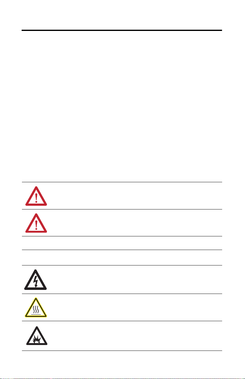
Safety Option
S = Safe off
Mounting Flange
B= IEC metric oversize
Brake
2 = No brake
4 = 24V DC brake
Shaft Key
J = Shaft key
K = No shaft key
Connectors
8 = Circular (SpeedTec) connector, right angle, 180° rotatable
Feedback
Q = 524,288 counts per revolution, 4096 turns
high-resolution multi-turn absolute encoder
Rated Speed
F = 3000 rpm
H = 3500 rpm
P = 5000 rpm
Magnet Stack Length
3 = 76.2 mm (3.0 in.)
4 = 101.6 mm (4.0 in.)
Frame Size
100 = 100 mm
115 = 115 mm
130 = 130 mm
Voltage Class
B = 400V
Network
S = Sercos
Series Type
F = Food grade enclosure (including shaft seal)
Series
MD = Premium permanent magnet rotary servo motor
with integrated drive
Catalog Number Explanation
MD F - S B xxx x x - Q x 8 x B - S
Rockwell Automation Publication MDF-IN001B-EN-P - August 2013
Page 5
Kinetix 6000M Integrated Drive-Motor 5
IMPORTANT
R
R
G
G
R
R
G
G
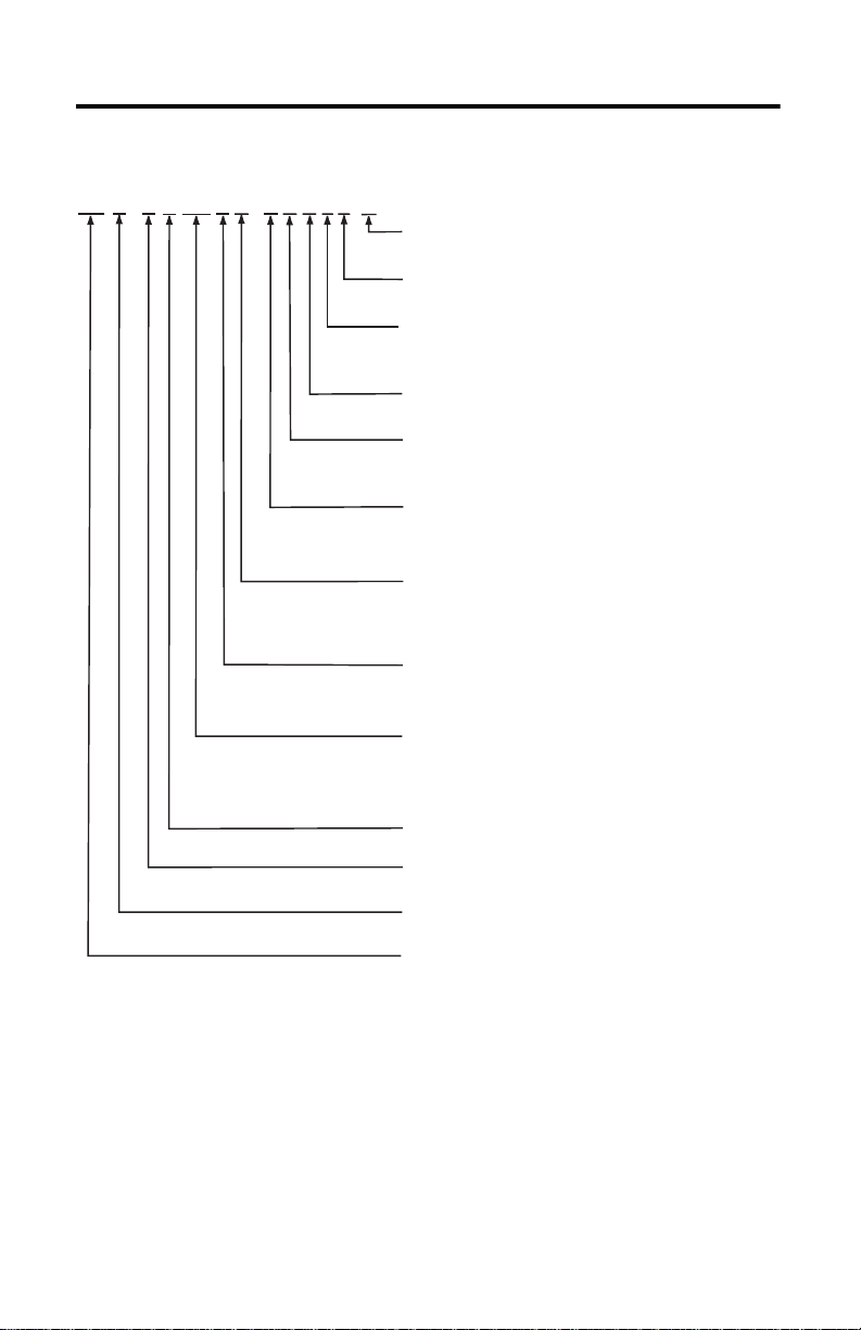
2090-CTSRP
Network Terminator
2090-CNSSPSS-12AAxx or
2090-CNSSPRS-AAxx (shown)
Network Cable
2090-CNSSPSS-AAxx, 2090-CNSRPRS-AAxx (shown),
2090-CNSSPRS-AAxx, or 2090-CNSRPSS-AAxx
Network Cable
2094-SEPM-B24-S
IPIM Module
2090-CHBIFS8-12AAxx
IPIM-to-IDM Hybrid Cable
Connects the IPIM Module to the First IDM Unit
2090-CHBP8S8-12AAxx
Hybrid Cable
2090-CTHP8
Hybrid Terminator
MDF-SB1xxx
Last IDM Unit
MDF-SB1xxx
First ID M Unit
Kinetix 6000M Integrated Drive-Motor System Cable Diagram
The colored rings on the hybrid connectors and the mating cable must match: red-to-red or
green-to-green.
Rockwell Automation Publication MDF-IN001B-EN-P - August 2013
Page 6
6 Kinetix 6000M Integrated Drive-Motor
1
2
3
4
5
6
7
8
9
1010
1111
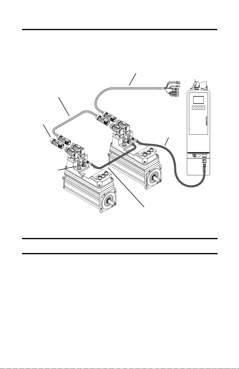
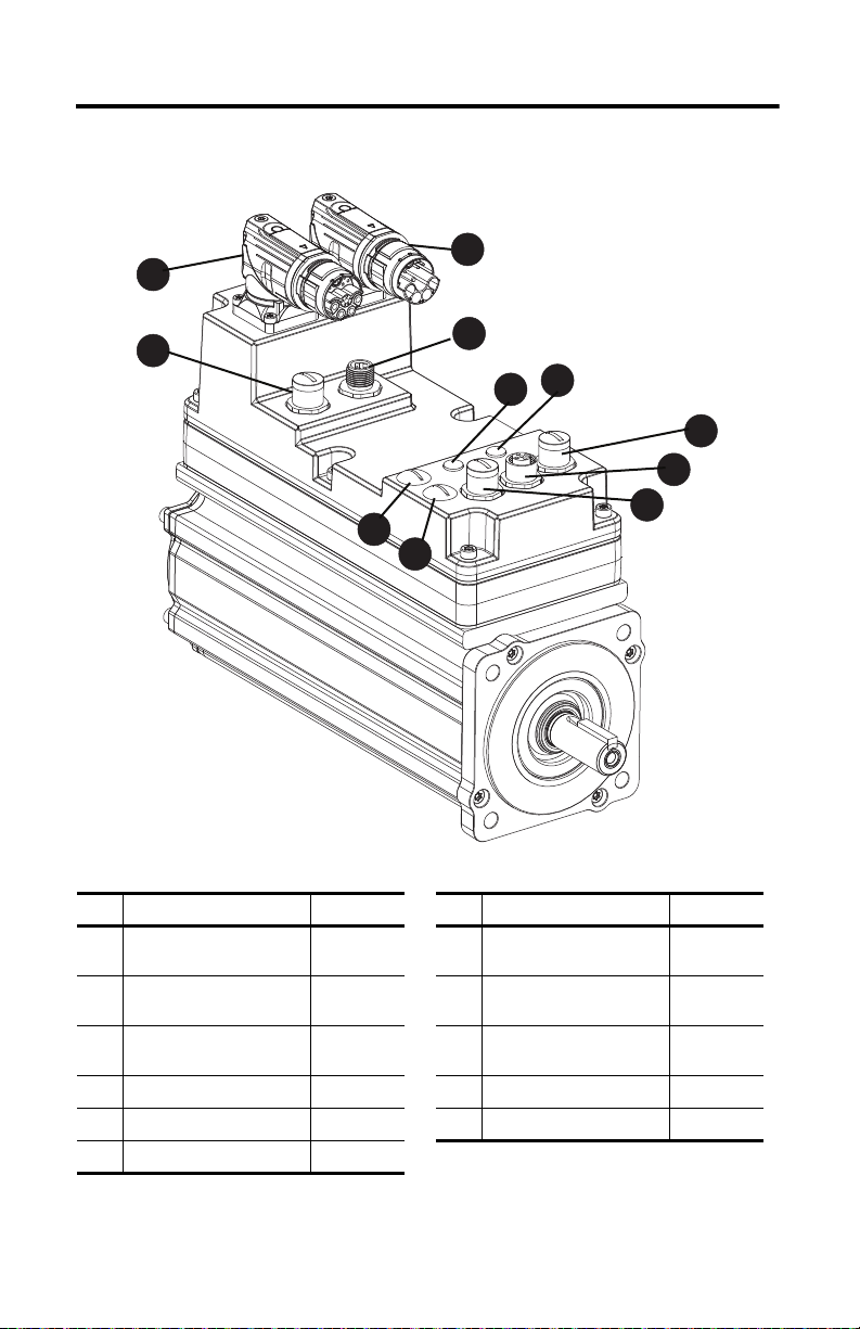
IDM Unit Connectors and Indicators
Item Description Panel ID Item Description Panel ID
1 Network In – 7
2 Hybrid In – 8
3 Hybrid Out – 9
4 Network Out – 10 Drive status indicator D
5 Node Address LSB (0…9) S1 11 Network status indic ator N
6 Node Address MSB (10…99) S10
Rockwell Automation Publication MDF-IN001B-EN-P - August 2013
Digital Input/Output 1:
Registration 2 and Overtravel -
Digital Input/Output 2:
Registration 1 and Overtravel +
Digital Input/Output 3:
Home and not used
1
2
3
Page 7
Kinetix 6000M Integrated Drive-Motor 7
Before You Begin
Remove all packing material, wedges, and braces from within and around the components. After
unpacking, check the item nameplate catalog number against the purchase order.
ATT EN TI ON : Do not attempt to open or modify the IDM unit. This manual describes modifications that
you can perform in the field, but do not attempt other changes. Only qualified Allen-Bradley
technicians can service an IDM unit.
Installation and Maintenance Guidelines
These guidelines advise you on how to install your product for safe and reliable service.
ATTENTION: Damage can occur to the bearings and the feedback device if sharp impact is applied to
the shaft during the installation of couplings and pulleys or when removing the shaft key. Damage to
the feedback device can also result by applying leverage to the faceplate to remove devices mounted
on the shaft. Do not strike the shaft, key, couplings, or pulleys with tools during installation or removal.
Use a wheel puller to apply pressure from the user-end of the shaft to remove any friction fit or stuck
device from the shaft.
A shaft seal is factory installed on an IDM unit. A shaft seal is required if any of these
environmental conditions exist:
• The IDM unit is exposed to fine dust.
• The IDM unit is exposed to fluids, or is attached to an oil-lubricated device.
• The IDM unit requires an IP65 or IP66 rating.
Replace the shaft seal at or before its expected lifetime of 12 months. Refer to Cables and
Accessory Kits on page
Refer to Specifications on page
19 for catalog numbers of shaft seal kits.
21 for a description of IP ratings.
Rockwell Automation Publication MDF-IN001B-EN-P - August 2013
Page 8
8 Kinetix 6000M Integrated Drive-Motor
IMPORTANT
Installing the Integrated Drive-Motor
Installing the IDM unit involves the proper alignment on the machine, effective cable shield
grounding, mounting the IDM unit, and connecting the cables.
Aligning the IDM Unit
The IDM unit can be mounted in any position. The mounting pilot aides in aligning the IDM
unit on a machine. Refer to Product Dimensions on page 11
mounting fasteners are preferred.
The installation must comply with all local regulations. The installer also must use equipment
and installation practices that promote electromagnetic compatibility and safety.
ATTENTION: Unmounted IDM units, disconnected mechanical couplings, loose shaft keys, and
disconnected cables are dangerous, if power is applied. Appropriately identify (tag-out) disassembled
equipment and restrict access to (lock-out) electrical power. Before applying power, remove the shaft
key and other mechanical couplings that could be thrown from the shaft.
Cable Shielding
Signal integrity is very important for successful operation of an IDM system, and proper signal
grounding is necessary to achieve this. The hybrid and network cables that connect one IDM to
another IDM are properly grounded through the daisy-chain connection to the Kinetix drive
system.
for these dimensions. Stainless steel
ATTENTION: High voltage can build up on hybrid cable shields, if the shield is not grounded. Verify
there is a connection to ground for all hybrid cable shields.
IDM system wiring differs from common PWM servo system wiring configurations; as hybrid and
network cables can be tie-wrapped together and occupy the same cable run. Hybrid and network
cables do not require physical segregation as a result of more effective wire shielding and i mproved
grounding techniques.
This exception applies to only the hybrid and network cables that connect to an IPIM module or
between IDM units, and does not apply to cabling elsewhere in a Kinetix drive system. Refer to the
drive user manuals listed in Additional Resources on page
Electrical Noise Reference Manual, publication GMC-RM001
National Electrical Code, local electrical codes, special operating temperature, duty cycles, or
system configurations take precedence over the information presented above and the values and
methods provided in the documents referenced above.
Rockwell Automation Publication MDF-IN001B-EN-P - August 2013
23, and the System Design for Control of
, for more information.
Page 9

Kinetix 6000M Integrated Drive-Motor 9
Mount and Connect the IDM Unit
To install an IDM unit, follow these procedures and recommendations.
ATT EN TI ON : The IDM unit connects to an IDM power interface module (IPIM) that stores residual
voltage for an extended period of time. Do not connect an IDM to an IPIM module immediately after
removing power to the IPIM module. Allow the residual power stored in the IPIM module to dissipate
for 60 seconds after power is removed from the IDM system. This extended discharge period is needed
for the system power to return to a nominal voltage that is acceptable for reconfiguration of the
system.
ATTENTION: Integrated drive-motor units are not intended for direct connection to an AC power line.
The IDM unit is designed for connection to an IPIM module that controls the application of power.
ATTENTION: To avoid damage to the bearings and feedback device, do not apply sharp impact to the
shaft during the installation or removal of couplings, pulleys, or shaft key.
1. Allow sufficient clearance around the IDM unit for it to stay within its specified
operating temperature range.
BURN HAZARD: Outer surfaces of the IDM unit can reach high temperatures, 125 °C
(275 °F), during operation. Take precautions to prevent accidental contact with hot surfaces
on the IDM unit. Consider the surface temperature of the equipment when selecting
equipment and cables for connection.
• Refer to Specifications on page 21 for the operating temperature range and
clearances.
• Obtain the specified thermal rating by mounting the IDM unit on a surface with
heat dissipation equivalent to a 304.8 x304.8 x 12.7 mm (12 x 12 x 0.5 in.)
aluminum heatsink.
• Do not install the IDM unit in an area with restricted airflow, and keep other heat
producing devices away from the IDM unit.
2. Refer to Load Force Ratings on page
limitations of the unit.
3. If sufficient mounting clearance is provided, rotate the hybrid cable connectors into
position prior to installing. If the mounting clearance is restricted, rotate after installing.
ATTENTION: Connectors are designed to be rotated into a fixed position during installation
and remain in that position without fur ther adjustment. Strictly limit the applied forces and
the number of times the connector is rotated to make sure that connectors meet the
specified IP ratings. Apply force to only the connector and cable plug. Do not apply force to
the cable extending from the cable plug. Do not use tools, for example pliers or vise-grips, to
assist with the rotation of the connector.
13 to determine the radial and axial shaft load
Rockwell Automation Publication MDF-IN001B-EN-P - August 2013
Page 10

10 Kinetix 6000M Integrated Drive-Motor
IMPORTANT
IMPORTANT
TIP
4. Position the IDM unit on the machine in any position.
IDM units with a brake (MDF-SBxxxxP-QJ84B-S) can require the use of a manual
brake-release cable to release the brake prio r to rotating the shaft so the IDM unit aligns
with the machine mounts. Refer to the Manual Brake Release Cable Installation
Instructions, publication 2090-IN037
5. Mount and align the IDM unit by using stainless steel bolts.
Product Dimensions on page 11
6. Form a drip loop in the cables directly before each cable connects to the IDM unit.
A drip loop is a low spot in the cable that lets liquids gather and drip off the cable rather
than flow along the cable to an electrical connection or the IDM unit.
ATT EN TI ON : To avoid arcing or unexpected motion, always remove power to the IDM unit
before connecting or disconnecting the hybrid or network cables.
The hybrid cables and network cables are UL Listed with insulation ratings of 1000V
and 105° C (221° F) and can be routed in a common wireway.
Refer to the Kinetix 6000M Integrated Drive-Motor System Cable Diagram diagram on
5 for a visual reference of cable positioning.
page
ATT EN TI ON : Make sure that installed cables are restrained to prevent uneven tension or
flexing at the cable connectors. Provide support at 3m (10ft) intervals throughout the cable
run. Excessive and uneven lateral force at the cable connectors can result in the connector’s
environmental seal opening and closing or wires separating at the cable gland as the cable
flexes.
list the mounting hole diameters.
, for more information.
7. Connect the network and hybrid cables after the IDM unit is mounted.
ATT EN TI ON : Cable connectors must be properly aligned before the connection is secured
with the recommended number of turns or torque value. Improper connector alignment is
indicated by the need for excessive force, such as the use of tools, to fully seat connectors.
• Torque a network M12 cable connector plug to 0.8…1.2 N•m (7…12 lb•in) to fully
seat the contacts and secure the connection.
The internal O-ring is self-conforming and requires a short period between each
connect/disconnect cycle to expand to full size. Allow at least one minute for the
O-ring expansion to occur before reconnecting a hybrid cable.
• Hand-tighten the knurled collar on the M23 hybrid cable approximately 45° to fully
seat and lock the connector.
The colored rings on the hybrid cable connector and the mating cable must match:
red-to-red or gree n-to-green.
Rockwell Automation Publication MDF-IN001B-EN-P - August 2013
Page 11

Kinetix 6000M Integrated Drive-Motor 11
Reinforcing Boss Extension on Front Faceplate
MDF-SB1003 = 2.5 (0.10)
MDF-SB1304 = 1.65 (0.07)
MDF-SB11153 = 2.0 (0.08)
Shaft Detail with Key
Detail A
Wear Collar / Shaft Shoulder
Flush to Pilot
Pilot Relief Ø
Use shaft end mark or shaft key to orient
encoder absolute position (0° ±10°).
S on M
S = Diameter of Mounting Holes
M = Diameter of Bolt Circle
MDF-SB1003P-Qx82B-S motor shown
See Detail A
Connector housing can be rotated
one-time within a range of 180°.
Pilot Height
Pilot Ø
Shaft End Threaded Hole
MDF-SB1003 IDM Units
Thread - M5 x 0.8-6H
Thread Depth - 12.5 (0.49)
MDF-SB1153 IDM Units
Thread - M6 x 1.0-6H
Thread Depth - 16 (0.63)
MDF-SB1304 IDM Units
Thread - M8 x 1.25-6H
Thread Depth - 19 (0.75)
Shaft Seal
Refer to page 19
for Kinetix 6000M
Integrated Drive-Motor
shaft seal kit information.
MDF-SB1003 = 5 x 5 x 22 Key
MDF-SB1003 = 6 x 6 x 24 Key
MDF-SB1003 = 8 x 7 x 31 Key
Pilot Relief Diameter
MDF-SB1003 = 53.3 (2.10)
MDF-SB1153 = 59.7 (2.35)
MDF-SB1304 = 71.1 (2.80)
Product Dimensions
Refer to the tables on page 12 for the physical dimensions shown in this figure.
L
LB
LD
LE
L- LB
D
AD
HD
63.6
(2.50)
P
P1
P1
MDF-SB1003 = 2.87 (0.113)
MDF-SB1153 = 2.87 (0.113)
MDF-SB1304 = 3.38 (0.133)
2.74 (0.108)
42.3
(1.66)
± 0.83 (0.032)
± 0.83 (0.032)
± 0.83 (0.032)
LA
N
2.74
(0.108)
F
G
Rockwell Automation Publication MDF-IN001B-EN-P - August 2013
Page 12

12 Kinetix 6000M Integrated Drive-Motor
Dimensions are for non-brake IDM units; footnotes provide tolerances and brake dimensions.
IDM Unit Dimensions
MDF-SB
1003
1153
1304
(1) Acceptable ra nge for this dimension is:
(2) For IDM units with a brake (MDF-SBxxxxxx-Qx84B), adjust dimensions with these values:
(3) Tolerance for this dimension is ±0.7 (±0.028).
AD
mm (in.)
173.8
(6.84)
178.2
(7.01)
185.8
(7.31)
MDF-SB1003 IDM units 15.997…16.008 (0.6298 …0.6301).
MDF-SB1153 IDM units 18.996…19.009 (0.7479 …0.7483).
MDF-SB1304 IDM units 23.996…24.009 (0.9448 …0.9451).
MDF-SB1003 catalog numbers add 34.5 (1.36) to L, LB, LD, and LE.
MDF-SB1153 catalog numbers add 48.5 (1.91) to L, LB, LD, and LE.
MDF-SB1304 catalog numbers add 48.5 (1.91) to L, LB, LD, and LE.
(1)
D
mm (in.)
16.0
(0.629)
19.0
(0.740)
24.0
(0.945)
F
mm (in.)G mm (in.)
5.0
(0.197)
6.0
(0.236)
8.0
(0.315)
12.95
(0.510)
15.40
(0.606)
19.82
(0.780)
HD
mm (in.)
221.0
(8.70)
229.0
(9.02)
244.7
(9.63)
(2)
L
mm (in.)
271.3
(10.685)
271.2
(10.675)
310.6
(12.23)
(3)
L-LB
mm (in.)
40.0
(1.575)
50.0
(1.969)
LA
mm (in.)
9.90
(0.39)
10.20
(0.40)
12.2
(0.48)
IDM Unit Dimensions (continued)
(1)
MDF-SB
1003
1153
1304
(1) For units with a brake (MDF-SB
(2) Dimen sion is to the rotation point of either connector.
(3) Dimension is to front of the male connector.
(4) Tolerance for MDF-SB1003 IDM Units = Ø 79.993…80.012 (3.1493…3.1501)
(5) Tolerance is +0.36 (±0.007).
LB
mm (in.)
231.3
(9.11)
231.2
(9.10)
260.6
(10.26)
MDF-SB1003 catalog numbers add 34.5 (1.36) to L, LB, LD, and LE.
MDF-SB1153 catalog numbers add 48.5 (1.91) to L, LB, LD, and LE.
MDF-SB1304 catalog numbers add 48.5 (1.91) to L, LB, LD, and LE.
Tolerance for MDF-SB1153 IDM Units = Ø 94.991…95.013 (3.7398…3.7407)
Tolerance for MDF-SB1304 IDM Units = Ø 109.991…110.013 (4.3303…4.3312)
(2)
LD
mm (in.)
183.0
(7.21)
183.3
(7.22)
212.0
(8.35)
xxxxxx-Qx
(3)
LE
mm (in.)
126.3
(4.97)
126.5
(4.98)
155.2
(6.11)
84B), adjust dimensions with these values:
M
mm (in.)
100.0
(3.937)
115.0
(4.528)
130.0
(5.118)
(4)
N
mm (in.)
80.0
(3.15)
95.0
(3.74)
110.0
(4.331)
P
mm (in.)P1mm (in.)
89.4
(3.52)
98.3
(3.87)
113.7
(4.48)
94.4
(3.72)
101.6
(4.0)
117.7
(4.63)
(5)
S
mm (in.)
7.0
(0.283)
10.0
(0.401)
Rockwell Automation Publication MDF-IN001B-EN-P - August 2013
Page 13

Kinetix 6000M Integrated Drive-Motor 13
Axial Load Force
Radial Load Force is applied at center of shaft extension.
Load Force Ratings
An IDM unit can operate with a sustained shaft load. The figure shows radial and axial load
force locations, and the tables provide maximum values for each force.
Load Forces on the Shaft
The tables represent 20,000 hour L10 bearing fatigue life at various loads and speeds. The 20,000
hour life does not account for possible application-specific life reduction that can occur due to
bearing grease contamination from external sources.
Loads are measured in pounds; kilograms are mathematical conversions.
Radial Load Force Ratings
Cat. No.
MDF-SB1003 – 74 (163) 59 (129) – 49 (107) 43 (95)
MDF-SB1153 106 (233) 84 (185) 67 (147 ) – 55 (121) –
MDF-SB1304 140 (309) 111(245) 89 (195) 77 (170) – –
500 rpm
kg (lb)
1000 rpm
kg (lb)
2000 rpm
kg (lb)
3000 rpm
kg (lb)
3500 rpm
kg (lb)
5000 rpm
kg (lb)
Axial Load Force Ratings with Maximum Radial Load
Cat. No.
MDF-SB1003 – 27 (59) 20 (44) – 16 (35) 13 (29)
MDF-SB1153 52 (114) 39 (86) 29 (64) – 22 (48) –
MDF-SB1304 49 (107) 36 (80) 27 (59) 22 (49) – –
500 rpm
kg (lb)
1000 rpm
kg (lb)
2000 rpm
kg (lb)
3000 rpm
kg (lb)
3500 rpm
kg (lb)
5000 rpm
kg (lb)
Axial Load Force Ratings with Zero Radial Load
Cat. No.
MDF-SB1003 – 36 (80) 27 (59) – 21 (47) 18 (40)
MDF-SB1153 69 (152) 51(112) 38 (87) – 30 (66) –
MDF-SB1304 69 (152) 51 (112) 38 (83) 31 (69) – –
500 rpm
kg (lb)
1000 rpm
kg (lb)
2000 rpm
kg (lb)
3000 rpm
kg (lb)
3500 rpm
kg (lb)
5000 rpm
kg (lb)
Rockwell Automation Publication MDF-IN001B-EN-P - August 2013
Page 14

14 Kinetix 6000M Integrated Drive-Motor
D
5
42
63
1
CB
A
E
9
7
8
10
Female Connector
A
1
24
36
5
BC
D
E
7
8
9
10
Male Connector
Connector Data
The following tables and illustrations provide connector pinouts for the IDM units. Refer to
IDM Unit Connectors and Indicators on page 6 for connector locations.
Hybrid Connector Pinout
Hybrid Output Connector Hybrid Input Connector
Pin Signal Name Pin Signal Name
A DC + A DC +
B DC - B DC -
C 42V + C 42V +
D 42V COM D 42V COM
E Protective Earth (PE) Ground E Protective Earth (PE) Ground
1
Reserved
2 2 Brake 24V +
3 3 Brake 24V COM
4 Safety Enable 1+ 4 Safety Enable 1+
5 Safety Enable - 5 Safety Enable -
6 Safety Enable 2+ 6 Safety Enable 2+
7 IDM CAN HI 7 IDM CAN HI
8 IDM CAN LO 8 IDM CAN LO
9 IDM SYSOKOUT 9 IDM SYSOKIN
10 IDM SYSOKRTN 10 IDM SYSOKRTN
1 Reserved
Rockwell Automation Publication MDF-IN001B-EN-P - August 2013
Page 15

Kinetix 6000M Integrated Drive-Motor 15
1
4
2
35
1
2
3
4
5
1
4
2
35
Female Connector
Network Connector Pinout
Network Output Connector Network Input Connector
Pin Signal Name Female Connector Pin S ignal Name Male Connector
1 TX+ 1 RX+
2 RTN RX+ 2 RTN TX-
3 RTN RX- 3 RTN TX+
4 TX- 4 RX-
5 REF 5 REF
Digital Input Connectors
24V digital I/O signals from machine-based sensors interface to the IDM unit through three
I/O connectors. Refer to IDM Unit Connectors and Indicators on page 6 for connector
locations.
ID Digital Inputs Pin Signal Name
1 I/O 24V +
2Overtravel -
Overtravel - and
1
Registration 2
Overtravel + and
2
Registration 1
3 Home
(1) Detailed information about the digital inputs is available in the Kinetix 6000M Integrated Drive-Motor
System User Manual, publication
3 I/O 24V COM
4 Registration 2
5 Shield/Chassis Ground
1 I/O 24V +
2Overtravel +
3 I/O 24V COM
4 Registration 1
5 Shield/Chassis Ground
1 I/O 24V +
2 Reserved
3 I/O 24V COM
4Home
5 Shield/Chassis Ground
2094-UM003
(1)
.
Connector Pinout
Allen-Bradley® Bulletin 889D and 879D micro-style patchcords, splitters, and V-cables are
compatible with the M12 digital I/O connectors on the IDM unit. Refer to Cables and
Accessory Kits on page 19
for a list of Kinetix 6000M system cable resources.
Rockwell Automation Publication MDF-IN001B-EN-P - August 2013
Page 16

16 Kinetix 6000M Integrated Drive-Motor
Node Address Switches
A unique network address for each IDM unit is set on the S1 and S10 rotary address switches.
Valid IDM addresses are 01…99. The least significant digit (0…9) is set on switch S1, and switch
S10 sets the most significant digit (10…90). Apply 0.6 N•m (5 lb•in) of torque to the switch
cover to environmentally seal the opening.
Refer to IDM Unit Connectors and Indicators on page 6
for connector location.
Network and Drive Status Indicators
Two multi-color indicators provide IDM network (N) and drive (D) status. Refer to IDM Unit
Connectors and Indicators on page 6 for status indicator locations.
Status Display Network (N) Drive (D)
Off No communication No power
Alternating green/red – Self test
(1)
Flashing green
Fast flashing green
Slow flashing green
Green Communicationready Normal operation
Flashing red
Red Duplicate address Non-recoverable fault
(1) Flashing rate is once per second. The fast flashing rate is twice per second, and the slow flashing rate is once every two seconds. A flash is defined as
one complete on/off cycle.
(2) Drive status is Standby while waiting for the n etwork communication to be established and transition to a Norma l operation state.
(3) A reset or cycling the power can clear a recoverable fault (depending on the state of the IDM unit).
(4) A non-recoverable fault requires power cycling to clear the fault and/or a hardware configuration modification performed while power is removed.
(1)
Firmware update in process –
(1)
(1)
–Recoverablefault
Establishing communication Standby
Firmware update in process
(on a different IDM unit)
(2)
–
(3)
(4)
Rockwell Automation Publication MDF-IN001B-EN-P - August 2013
Page 17

Kinetix 6000M Integrated Drive-Motor 17
Radial Cut at
End of Keyway
Support for Shaft
and IDM Unit
Key Alig nment
Remove and Replace Shaft Keys and Shaft Seals
IDM units are available with or without a slot for a shaft key, but a shaft key is recommended.
The shaft seal provides environmental sealing for the integrated drive-motor. IDM units are
shipped with a PTFE (polytetrafluoroethylene) shaft seal installed.
Remove and Replace Shaft Keys
The IDM unit must be dismounted from a machine to remove or replace the shaft key, and this
procedure assumes that task has already been completed.
Shaft keys for IDM units are constructed of stainless steel - 300 series. The design tolerances
create an interference fit (slightly larger than the opening) that is a secure and rigid fit for the
mating connection.
ATTENTION: Damage can occur to the bearings and the feedback device if sharp impact is applied to
the shaft during the installation of couplings and pulleys or when removing the shaft key. Damage to
the feedback device can also result by applying leverage to the faceplate to remove devices mounted
on the shaft. Do not strike the shaft, key, couplings, or pulleys with tools during installation or removal.
Use a wheel puller to apply pressure from the user-end of the shaft to remove any friction fit or stuck
device from the shaft.
Perform one of these actions to remove a shaft key:
• Lift the key by grasping it with a pliers or similar tool.
• Lever the key with a screwdriver inserted between the key and the slot.
Follow these steps to replace a shaft key.
1. Verify the replacement key matches the keyway in the shaft and the mating mechanical
connection (for example, a coupling or pulley) before proceeding.
2. Align the front of the key with the front of the shaft.
This prevents the radial end-of-cut at the body of the IDM unit from interfering with
the correct seating of the key.
3. Support the underside of the shaft diameter with a fixture and use a controlled press
device to apply a constant force across the top surface, to press the key into the shaft.
Rockwell Automation Publication MDF-IN001B-EN-P - August 2013
Page 18

18 Kinetix 6000M Integrated Drive-Motor
TIP
IMPORTANT
TIP
Remove and Replace Shaft Seals
Shaft seals must be lubricated by using a food-grade polyurea base grease, such as ChevronSM
FM (NLGI 2). Shaft seals are typically replaced at 12-month intervals. Lubricant is supplied the
kit.
ATTENTION: Damage to the shaft surface where the seal makes contact can cause excessive wear and
early failure of the shaft seal. Use care to prevent scratching or damage to the mounting sur face or to
the IDM shaft.
Remove the shaft key, if the IDM unit is so equipped, before rem oving or repla cing the shaf t seal. Refer
to Remove and Replace Shaft Keys on page
17.
Refer to Shaft Seal Kits on page
19 for shaft seal catalog numbers.
Remove the Shaft Seal
The shaft seal can be safely removed by grasping an edge of the shaft seal with a needle-nose
pliers or similar tool. Lift and slightly rotate the seal while pulling it parallel to the shaft and away
from the body of the IDM unit.
Replace the Shaft Seal
No tools are required to install the replacement shaft seal.
1. Apply the lubricant (provided with the kit) to the inner ring of the shaft seal and the
IDM wear sleeve.
2. Center the seal on the shaft with the seal oriented with the sealing lip positioned and
slanting outward, and slide the seal along the shaft toward the mounting surface of the
IDM unit.
3. Press the shaft seal into the seal recess by applying pressure with your fingertips in a
circular fashion that slowly seats the shaft seal.
Do not bottom out the shaft seal. Proper seating of the shaft seal to a specific depth is
critical to prolonging the life of your motor.
Insert the shaft seal so the outer diameter of the seal is 1.0 mm (0.04 in.) beneath the
front surface of the motor.
4. Verify the outer and inner circumference of the shaft seal is fully seated into position.
You can verify the proper shaft-seal seating by running your fingertip around the
seal-to-IDM joint to feel for irregularities in the shaft seal or an uneven alignment where
the shaft seal contacts the IDM mounting surface.
Rockwell Automation Publication MDF-IN001B-EN-P - August 2013
Page 19
Kinetix 6000M Integrated Drive-Motor 19
Cables and Accessory Kits
Factory manufactured cables are available in standard cable lengths. They provide the required
shielding and signal termination.
For more cable information, contact your nearest Rockwell Automation sales office.
Resource Description
Kinetix Motion Accessories Specifications Technical Data,
publication GMC-TD004
Connection Systems Quick Selection Guide,
publication CNSYS-BR001
On-Machine™ Connectivity Catalog, publication M117-CA001
Shaft Seal Kits
IDM Unit Cat. No. Shaft Seal Cat. No.
MDF-SB1003 MPF-SST-A3B3 23 (0.90) 47 (1.85) 6 (0.24)
MDF-SB1153 MPF-SST-A4B4 26 (1.02) 52 (2.05) 6 (0.24)
MDF-SB1304 MPF-SST-A45B45 31 (1.22) 62 (2.44) 7 (0.27)
Inside Diameter
mm (in.)
Provides cable catalog numbers and descriptions
specifically for Kinetix 6000M IDM systems.
Provides catalog numbers and descriptions for the most
popular Allen-Bradley patchcord specifications.
Provides complete information for Allen-Bradley
patchcord specifications.
Shaft Seal Dimensions
Outside Diameter
mm (in.)
Width
mm (in.)
Shaft seals require a PTFE lubricant to reduce wear. The lubricant is provided in the kit.
Rockwell Automation Publication MDF-IN001B-EN-P - August 2013
Page 20
20 Kinetix 6000M Integrated Drive-Motor
IMPORTANT
Air Fitting
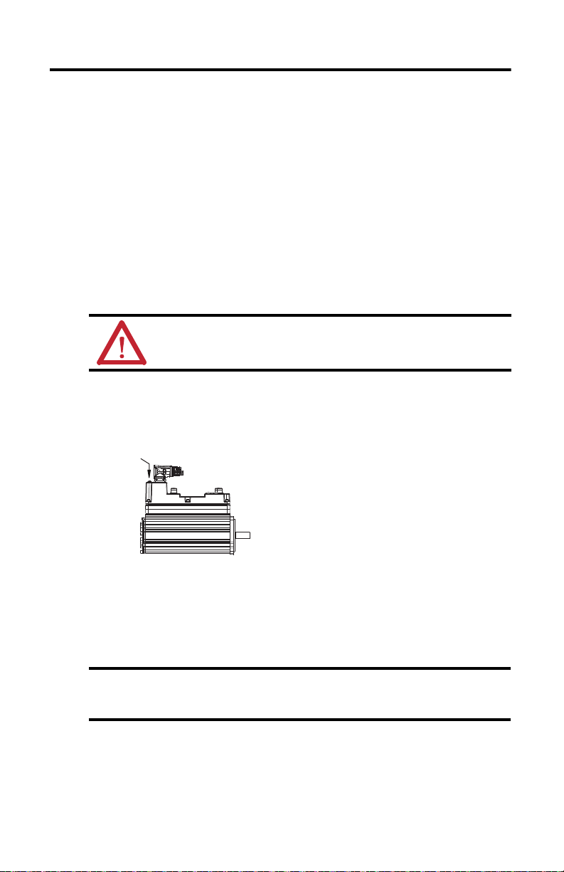
Sealing Air Accessory Kit
The sealing air pressure kit (catalog number MPS-AIR-PURGE) is available for field
installation.
The kit provides a quick-release female air fitting. Positive air pressure applied to the IDM unit
creates an additional level of protection against the ingress of foreign substances and moisture.
Sealing Air Accessory Kit Guidelines
You must supply these items, to connect to the sealing plug :
• Plastic air tubing must be 4 mm (5/32 in.) OD Teflon FEP tubing.
• Air supplied to an IDM unit must not exceed 0.1 bar (1.45 psi).
ATT EN TI ON : Air supplied to the IDM unit must be clean, dr y, and of instrument quality.
Maximum air pressure is 0.1 bar (1.45 psi). Excessive air pressure or improper filtering of air
can result in damage to the IDM unit.
Sealing Air Accessory Kit Installation
1. Remove the 5 mm (0.20 in.) sealing plug with a Phillips screwdriver.
2. Inspect the air fitting and the opening to verify the surface area is undamaged and the
contact area is clean.
3. Install the air tubing by using a 2.5 mm hex bit and torque the air fitting to 1.1…1.2 N•m
(10…12 lb•in).
4. Visually inspect the circumference of the connection for proper seating.
Be careful while rotating the hybrid connectors when a sealing air fitting is installed.
The minimal clearance between the air fitting and the connectors can result in a pinch
point.
Rockwell Automation Publication MDF-IN001B-EN-P - August 2013
Page 21

Kinetix 6000M Integrated Drive-Motor 21
Specifications
Attribute Value
(1)
Mounting clearance
Temperature, operating 0…40 °C (32…104 °F)
Temperature, storage -30…70 °C (-2 …158 °F)
Relative humidity 5…95% noncondensing
Atmosphere Noncorrosive
Paint USDA compliant food grade
(2) (3)
IP rating
Connector, install torque/rotation
• Digital I/O - M12
• Hybrid - M23
• Network - M12
• Sealing air fitting
Cover screw, seal ing torque
• Digital I/O (1, 2, 3)
• Node address (S1, S10)
(1) Mounting clearance is the physi cal separation in any direction between the IDM unit and other components that produce heat.
(2) The following are the IPx6 water spray test condi tions.
• General conditions are three minutes of operation, at all angles from a distance of 2.5…3.0 m (98…118 in.).
• Spray conditions are 100 liters per minute (26.4 gp m) through a 12.5 mm (0.5 in.) nozzle, with ~1 bar (14.5 psi) at the nozzle.
• The spray is water, at room temperature. Chemical or cleaning solutions are excluded.
(3) Ingress rating of IP66 is si milar to a NEMA 35 (dust tight, drip tight).
(4) The integrated drive-motors are ingress protec tion rated (IP rating) as a measure of their environmenta l protection.
The IP rating excludes any reduction in the rating resulting from cables or their p lugs.
(5) Refer to Shaft Seal Kits on page
100 mm (3.9 in.)
Bulletin MDF housings are rated IP66 (dust tight, powerful water jets)
with a shaft seal installed
(5)
0.8…1.2 N•m (7…12 lb•in)
45° rotation, self-locking
0.8…1.2 N•m (7…12 lb•in)
1.1…1.2 N•m (10…12 lb•in)
0.6 N•m (5 lb•in)
0.6 N•m (5 lb•in)
19 for installation instructions.
(4)
Additional specifications for interconnect cables and accessories are available in the Kinetix
Motion Control Accessories Technical Data, publication GMC-TD004
.
Rockwell Automation Publication MDF-IN001B-EN-P - August 2013
Page 22

22 Kinetix 6000M Integrated Drive-Motor
Motor Overload Protection
This servo drive uses solid-state motor overload protection that operates in accordance with
UL 508C. Motor overload protection is provided by algorithms (thermal memory) that predict
actual motor temperature based on operating conditions as long as control power is continuously
applied. However, when control power is removed, thermal memory is not retained.
In addition to thermal memory protection, this drive provides an input for an external
temperature sensor/thermistor device, embedded in the motor, to support the UL requirement
for motor overload protection.
Some motors supported by this drive do not contain temperature sensors/thermistors; therefore,
motor overload protection against excessive consecutive motor overloads with power cycling is
not supported.
This servo drive meets the following UL 508C requirements for solid-state overload protection.
Motor Overload Protec tion Trip Point Value
Ultimately 100% overload
Within 8 minutes 200% overload
Within 20 seconds 600% overload
ATTENTION: To avoid damage to your motor due to overheating caused by excessive,
successive motor overload trips, follow the wiring diagram provided in the user manual for
your motor and drive combination.
Refer to your servo drive user manual for the interconnect diagram that illustrates the wiring
between your motor and drive.
Rockwell Automation Publication MDF-IN001B-EN-P - August 2013
Page 23
Kinetix 6000M Integrated Drive-Motor 23
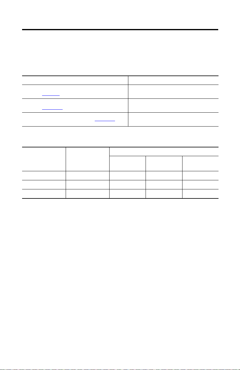
Additional Resources
These documents contain additional information concerning related products from
Rockwell Automation.
Resource Description
Kinetix IPIM to IDM Hybrid Cable Installation Instructions,
publication 2090-IN031
Kinetix 6000 Multi-axis Servo Drive User Manual,
publication 2094-UM001
Kinetix 6200 and Kinetix 6500 Multi-axis Ser vo Drive User Manual,
publication 2094-UM002
Kinetix IPIM to IDM Hybrid Cable Installation Instructions,
publication 2090-IN031
Kinetix Hybrid Cable Installation Instructions,
publication 2090-IN032
Kinetix Network Cable Installation Instructions,
publication 2090-IN034
Kinetix Hybrid Terminator Installation Instructions,
publication 2090-IN035
Kinetix Network Terminator Installation Instructions,
publication 2090-IN036
Kinetix Brake Override Cable Installation Instructions,
publication 2090-IN037
Kinetix 6000M Bulkhead Cable Adapter Kit Installation Instructions,
publication 2090-IN039
System Design for Control of Electrical Noise Reference Manual,
publication GMC-RM001
Information on the installation of
components and accessories compatible with
Kinetix 6000M integrated drive-motor
systems.
How to minimize and control system-level
electrical noise.
You can view or download publications at http://www.rockwellautomation.com/literature
To order copies of technical documentation, contact your local Allen-Bradley distributor or
Rockwell Automation sales representative.
Rockwell Automation Publication MDF-IN001B-EN-P - August 2013
.
Page 24

Rockwell Automation Support
Rockwell Automation provides tec hnical information on the Web to assist you in using its products.
At http://www.rockwellautomation.com/support
service packs. You can also visit our Support Center at https://rockwellautomation.custhelp.com/
and forums, technical information, FAQs, and to sign up for product notification updates.
In addition, we offer multiple support programs for installation, configuration, and troubleshooting. For more information, contact
your local distributor or Rockwell Automation representative, or visit http://w ww.rockwellautomation.com/services/online-phone
Installation Assistance
If you experience a problem within the first 24 hours of installation, please review the information that's contained in this manual.
You can also contact a special Customer Support number for initial help in getting your product up and running.
United States or Canada 1.440.646.3434
Outside United States or
Canada
Use the Wor ldwi de Loc ator
http://www.rockwellautomation.com/rockwellautomation/support/overview.page
local Rockwell Automation representative.
New Product Satisfaction Return
Rockwell Automation tests all of its products to help ensure that they are fully operational when shipped from the manufacturing
facility. However, if your product is not functi oning and needs to be returned, follow these procedures.
you can find technical and application notes, sample code, and links to software
for software updates, support chats
at
, or contact your
.
United States
Outside United States Please contact your local Rockwell Automation representative for the return procedure.
Contact your distributor. You must provide a Customer Support case number (call the phone number
above to obtain one) to your distributor to complete the return process.
Documentation Feedback
Your comments will help us serve your documentation needs better. If you have any suggestions on how to improve this document,
complete this form, publication RA-DU002
Allen-Bradley, CompactLogix, ControlLogix, Kinetix, On-Machine, Rockwell Software, Rockwell Automation, and SoftLogix are trademarks of
Rockwell Automation, Inc.
Trademarks not belonging to Rockwell Automation are property of their respective companies.
Rockwell Otomasyon Ticaret A.Ş., Kar Plaza İş Merkezi E Blok Kat:6 34752 İçerenköy, İstanbul, Tel: +90 (216) 5698400
Publication MDF-IN001B-EN-P - August 2013 PN-215239
Supersedes Publication MDF-IN001A-EN-P - February 2012 Copyright © 2013 Rockwell Automation, Inc. All rights reserved. Printed in the U.S.A.
, available at http://www.rockwellautomation.com/literature/.
 Loading...