

Page 1

User Manual
Kinetix 6000M Integrated Drive-Motor System
Catalog Numbers 2094-SEPM-B24-S, MDF-SB1003P, MDF-SB1153H, MDF-SB1304F
Page 2
Important User Information
IMPORTANT
Solid-state equipment has operational characteristics differing from those of electromechanical equipment. Safety
Guidelines for the Application, Installation and Maintenance of Solid State Controls (publication SGI-1.1
your local Rockwell Automation® sales office or online at http://www.rockwellautomation.com/literature/
important differences between solid-state equipment and hard-wired electromechanical devices. Because of this difference,
and also because of the wide variety of uses for solid-state equipment, all persons responsible for applying this equipment
must satisfy themselves that each intended application of this equipment is acceptable.
In no event will Rockwell Automation, Inc. be responsible or liable for indirect or consequential damages resulting from the
use or application of this equipment.
The examples and diagrams in this manual are included solely for illustrative purposes. Because of the many variables and
requirements associated with any particular installation, Rockwell Automation, Inc. cannot assume responsibility or
liability for actual use based on the examples and diagrams.
No patent liability is assumed by Rockwell Automation, Inc. with respect to use of information, circuits, equipment, or
software described in this manual.
Reproduction of the contents of this manual, in whole or in part, without written permission of Rockwell Automation,
Inc., is prohibited.
Throughout this manual, when necessary, we use notes to make you aware of safety considerations.
available from
) describes some
WARNING: Identifies information about practices or circumstances that can cause an explosion in a hazardous environment,
which may lead to personal injury or death, property damage, or economic loss.
ATTENTION: Identifies information about practices or circumstances that can lead to personal injury or death, property
damage, or economic loss. Attentions help you identify a hazard, avoid a hazard, and recognize the consequence.
SHOCK HAZARD: Labels may be on or inside the equipment, for example, a drive or motor, to alert people that dangerous
voltage may be present.
BURN HAZARD: Labels may be on or inside the equipment, for example, a drive or motor, to alert people that surfaces may
reach dangerous temperatures.
Identifies information that is critical for successful application and understanding of the product.
Allen-Bradley, Rockwell Software, Rockwell Automation, Kinetix, On-Machine, ControlLogix, CompactLogix, SoftLogix, RSLinx, RSLogix, DriveExplorer, ControlFLASH and TechConnect are trademarks of
Rockwell Automation , Inc.
Trademarks not belonging to Rockwell Automation are property of their respective companies.
Page 3

Table of Contents
Preface
Start
Planning the Kinetix 6000M System
Installation
About This Publication. . . . . . . . . . . . . . . . . . . . . . . . . . . . . . . . . . . . . . . . . . . . 7
Conventions Used in This Manual . . . . . . . . . . . . . . . . . . . . . . . . . . . . . . . . . 7
Additional Resources . . . . . . . . . . . . . . . . . . . . . . . . . . . . . . . . . . . . . . . . . . . . . . 7
Chapter 1
About the Kinetix 6000M System . . . . . . . . . . . . . . . . . . . . . . . . . . . . . . . . . . 9
Typical Hardware Configurations . . . . . . . . . . . . . . . . . . . . . . . . . . . . . . . . . 11
Typical Communication Configurations . . . . . . . . . . . . . . . . . . . . . . . . . . . 16
Catalog Number Explanations . . . . . . . . . . . . . . . . . . . . . . . . . . . . . . . . . . . . 17
Component Compatibility. . . . . . . . . . . . . . . . . . . . . . . . . . . . . . . . . . . . . . . . 18
Agency Compliance . . . . . . . . . . . . . . . . . . . . . . . . . . . . . . . . . . . . . . . . . . . . . . 19
CE Requirements (system without LIM module). . . . . . . . . . . . . . . . 19
CE Requirements (system with LIM module). . . . . . . . . . . . . . . . . . . 19
Chapter 2
Cable Length Restrictions and System Sizing . . . . . . . . . . . . . . . . . . . . . . . 21
IPIM Module Design Guidelines . . . . . . . . . . . . . . . . . . . . . . . . . . . . . . . . . . 22
System Mounting Requirements . . . . . . . . . . . . . . . . . . . . . . . . . . . . . . . 22
Circuit Breaker/Fuse Options . . . . . . . . . . . . . . . . . . . . . . . . . . . . . . . . . 23
Enclosure Selection . . . . . . . . . . . . . . . . . . . . . . . . . . . . . . . . . . . . . . . . . . . 24
Minimum Clearance Requirements . . . . . . . . . . . . . . . . . . . . . . . . . . . . 25
IDM Unit Design Guidelines . . . . . . . . . . . . . . . . . . . . . . . . . . . . . . . . . . . . . 26
Minimum Clearance Requirements . . . . . . . . . . . . . . . . . . . . . . . . . . . . 26
Electrical Noise Reduction . . . . . . . . . . . . . . . . . . . . . . . . . . . . . . . . . . . . . . . . 27
Cable Categories for Kinetix 6000M System . . . . . . . . . . . . . . . . . . . . 28
Mounting the Kinetix 6000M System
Chapter 3
Mounting the IPIM Module . . . . . . . . . . . . . . . . . . . . . . . . . . . . . . . . . . . . . . 30
Using the 2094 Mounting Brackets . . . . . . . . . . . . . . . . . . . . . . . . . . . . 30
Installing the 2094 Power Rail . . . . . . . . . . . . . . . . . . . . . . . . . . . . . . . . . 30
Determine Mounting Order. . . . . . . . . . . . . . . . . . . . . . . . . . . . . . . . . . . 30
Mount the IPIM Module . . . . . . . . . . . . . . . . . . . . . . . . . . . . . . . . . . . . . 32
Installing the IDM Unit . . . . . . . . . . . . . . . . . . . . . . . . . . . . . . . . . . . . . . . . . . 33
Aligning the IDM Unit . . . . . . . . . . . . . . . . . . . . . . . . . . . . . . . . . . . . . . . 34
Mount and Connect the IDM Unit . . . . . . . . . . . . . . . . . . . . . . . . . . . . 34
Rockwell Automation Publication 2094-UM003A-EN-P - May 2012 3
Page 4

Table of Contents
Chapter 4
Kinetix 6000M System Connector
Data
Connecting the Kinetix 6000M
System
IPIM Module Connectors and Indicators . . . . . . . . . . . . . . . . . . . . . . . . . . 38
IPIM Module Connector and Signal Descriptions . . . . . . . . . . . . . . . . . . 39
Hybrid Cable DC Bus Connector . . . . . . . . . . . . . . . . . . . . . . . . . . . . . 39
Hybrid Cable Communication Signals Connector . . . . . . . . . . . . . . 39
Safe Torque-off Connector. . . . . . . . . . . . . . . . . . . . . . . . . . . . . . . . . . . . 40
Sercos Fiber-optic Connectors . . . . . . . . . . . . . . . . . . . . . . . . . . . . . . . . . 41
Enable Input . . . . . . . . . . . . . . . . . . . . . . . . . . . . . . . . . . . . . . . . . . . . . . . . . 41
EtherNet/IP Connectors. . . . . . . . . . . . . . . . . . . . . . . . . . . . . . . . . . . . . . 42
IPIM Module Network Connector Pinouts. . . . . . . . . . . . . . . . . . . . . 42
IDM Unit Connectors and Indicators . . . . . . . . . . . . . . . . . . . . . . . . . . . . . 43
IDM Unit Connector and Signal Descriptions. . . . . . . . . . . . . . . . . . . . . . 44
Hybrid Cable Connector. . . . . . . . . . . . . . . . . . . . . . . . . . . . . . . . . . . . . . 44
IDM Network Input and Output Connector Pinouts . . . . . . . . . . . 45
Digital Input Connectors . . . . . . . . . . . . . . . . . . . . . . . . . . . . . . . . . . . . . 45
Power Specifications. . . . . . . . . . . . . . . . . . . . . . . . . . . . . . . . . . . . . . . . . . . . . . 50
Brake Override Input . . . . . . . . . . . . . . . . . . . . . . . . . . . . . . . . . . . . . . . . . 50
Peak Duty Cycle. . . . . . . . . . . . . . . . . . . . . . . . . . . . . . . . . . . . . . . . . . . . . . 50
Feedback Specifications. . . . . . . . . . . . . . . . . . . . . . . . . . . . . . . . . . . . . . . . . . . 52
Absolute Position. . . . . . . . . . . . . . . . . . . . . . . . . . . . . . . . . . . . . . . . . . . . . 52
Chapter 5
Basic Wiring Requirements . . . . . . . . . . . . . . . . . . . . . . . . . . . . . . . . . . . . . . . 53
Routing the Power and Signal Cables. . . . . . . . . . . . . . . . . . . . . . . . . . . 54
Grounding the IDM System . . . . . . . . . . . . . . . . . . . . . . . . . . . . . . . . . . . . . . 54
Apply the Cable Shield Clamp. . . . . . . . . . . . . . . . . . . . . . . . . . . . . . . . . 55
General IDM System Wiring. . . . . . . . . . . . . . . . . . . . . . . . . . . . . . . . . . . . . . 56
Hybrid Cable . . . . . . . . . . . . . . . . . . . . . . . . . . . . . . . . . . . . . . . . . . . . . . . . 56
Network Cable. . . . . . . . . . . . . . . . . . . . . . . . . . . . . . . . . . . . . . . . . . . . . . . 58
How to Bypass an IDM Unit. . . . . . . . . . . . . . . . . . . . . . . . . . . . . . . . . . . . . . 58
The Sercos Fiber-optic Ring. . . . . . . . . . . . . . . . . . . . . . . . . . . . . . . . . . . . . . . 59
Ethernet Cable Connections . . . . . . . . . . . . . . . . . . . . . . . . . . . . . . . . . . . . . . 63
4 Rockwell Automation Publication 2094-UM003A-EN-P - May 2012
Page 5

Chapter 6
Table of Contents
Configuring the Kinetix 6000M
System
Configure the Kinetix 6000M Integrated Drive-motor System . . . . . . . 65
Understanding the IPIM Module Display . . . . . . . . . . . . . . . . . . . . . . . . . . 66
Startup Sequence . . . . . . . . . . . . . . . . . . . . . . . . . . . . . . . . . . . . . . . . . . . . . 67
Information Display . . . . . . . . . . . . . . . . . . . . . . . . . . . . . . . . . . . . . . . . . . 67
Tools Menu. . . . . . . . . . . . . . . . . . . . . . . . . . . . . . . . . . . . . . . . . . . . . . . . . . 68
Configuring the IPIM Module . . . . . . . . . . . . . . . . . . . . . . . . . . . . . . . . . . . . 69
Setting the IPIM Module Network Address . . . . . . . . . . . . . . . . . . . . 69
Configuring the IDM Unit . . . . . . . . . . . . . . . . . . . . . . . . . . . . . . . . . . . . . . . 70
Setting the Node Address . . . . . . . . . . . . . . . . . . . . . . . . . . . . . . . . . . . . . 70
Add-on Profiles . . . . . . . . . . . . . . . . . . . . . . . . . . . . . . . . . . . . . . . . . . . . . . . . . . 73
Configure the Logix Sercos Interface Module . . . . . . . . . . . . . . . . . . . . . . . 73
Configure the Logix Controller. . . . . . . . . . . . . . . . . . . . . . . . . . . . . . . . 73
Configure the Logix Module . . . . . . . . . . . . . . . . . . . . . . . . . . . . . . . . . . 75
Configure the IDM Units . . . . . . . . . . . . . . . . . . . . . . . . . . . . . . . . . . . . . 77
Configure the Motion Group. . . . . . . . . . . . . . . . . . . . . . . . . . . . . . . . . . 79
Configure Axis Properties . . . . . . . . . . . . . . . . . . . . . . . . . . . . . . . . . . . . . 80
Download the Program . . . . . . . . . . . . . . . . . . . . . . . . . . . . . . . . . . . . . . . 81
Apply Power to the System. . . . . . . . . . . . . . . . . . . . . . . . . . . . . . . . . . . . . . . . 82
Test and Tune the Axes. . . . . . . . . . . . . . . . . . . . . . . . . . . . . . . . . . . . . . . . . . . 83
Test the Axes. . . . . . . . . . . . . . . . . . . . . . . . . . . . . . . . . . . . . . . . . . . . . . . . . 83
Tune the Axes. . . . . . . . . . . . . . . . . . . . . . . . . . . . . . . . . . . . . . . . . . . . . . . . 85
Troubleshooting the Kinetix 6000M
System
Removing and Replacing the
Kinetix 6000M IPIM Module
Chapter 7
Safety Precautions . . . . . . . . . . . . . . . . . . . . . . . . . . . . . . . . . . . . . . . . . . . . . . . . 87
IDM System Error Codes . . . . . . . . . . . . . . . . . . . . . . . . . . . . . . . . . . . . . . . . . 87
Reading the Fault Status of the IPIM Module. . . . . . . . . . . . . . . . . . . 88
Interpret Status Indicators . . . . . . . . . . . . . . . . . . . . . . . . . . . . . . . . . . . . . . . . 90
IPIM Module Status Indicators . . . . . . . . . . . . . . . . . . . . . . . . . . . . . . . . 90
IDM Unit Status Indicators . . . . . . . . . . . . . . . . . . . . . . . . . . . . . . . . . . . 91
General System Anomalies . . . . . . . . . . . . . . . . . . . . . . . . . . . . . . . . . . . . . . . . 92
IPIM Module Fault Diagnosis. . . . . . . . . . . . . . . . . . . . . . . . . . . . . . . . . . . . . 93
IPIM Module Fault Types. . . . . . . . . . . . . . . . . . . . . . . . . . . . . . . . . . . . . 94
IDM Unit Fault Diagnosis . . . . . . . . . . . . . . . . . . . . . . . . . . . . . . . . . . . . . . . . 95
Logix Controller/IDM Unit Fault Behavior . . . . . . . . . . . . . . . . . . . . 95
Use a Web Browser to Monitor System Status . . . . . . . . . . . . . . . . . . . . . . 97
Chapter 8
Before You Begin. . . . . . . . . . . . . . . . . . . . . . . . . . . . . . . . . . . . . . . . . . . . . . . . . 99
Remove the IPIM Module . . . . . . . . . . . . . . . . . . . . . . . . . . . . . . . . . . . . . . . 100
Replace the IPIM Module. . . . . . . . . . . . . . . . . . . . . . . . . . . . . . . . . . . . . . . . 101
Rockwell Automation Publication 2094-UM003A-EN-P - May 2012 5
Page 6

Table of Contents
Appendix A
Using the Safe Torque-off Feature
with the Kinetix 6000M System
Interconnect Diagram
Certification . . . . . . . . . . . . . . . . . . . . . . . . . . . . . . . . . . . . . . . . . . . . . . . . . . . . 103
Important Safety Considerations . . . . . . . . . . . . . . . . . . . . . . . . . . . . . 103
Category 3 Requirements According to EN ISO 13849-1 . . . . . . . 104
Stop Category Definition . . . . . . . . . . . . . . . . . . . . . . . . . . . . . . . . . . . . 104
Performance Level (PL) and Safety Integrity Level (SIL) . . . . . . . . 104
Description of Operation . . . . . . . . . . . . . . . . . . . . . . . . . . . . . . . . . . . . . . . . 104
Troubleshooting the Safe Torque-off Function . . . . . . . . . . . . . . . . 105
PFD, PFH, and MTTFd Definitions. . . . . . . . . . . . . . . . . . . . . . . . . . . . . . 107
PFD, PFH, and MTTFd Data. . . . . . . . . . . . . . . . . . . . . . . . . . . . . . . . . . . . 107
Wiring Your Safe Torque-off Circuit . . . . . . . . . . . . . . . . . . . . . . . . . . . . . 107
European Union Directives . . . . . . . . . . . . . . . . . . . . . . . . . . . . . . . . . . 108
IDM Safe Torque-off Feature . . . . . . . . . . . . . . . . . . . . . . . . . . . . . . . . . . . . 108
Safe Torque-off Feature Bypass . . . . . . . . . . . . . . . . . . . . . . . . . . . . . . . 109
IDM System Safe Torque-off Example . . . . . . . . . . . . . . . . . . . . . . . . . . . . 109
Cascading the Safe Torque-off Signal . . . . . . . . . . . . . . . . . . . . . . . . . . . . . 110
Safe Torque-off Signal Specifications. . . . . . . . . . . . . . . . . . . . . . . . . . . . . . 111
Appendix B
Upgrading the Kinetix 6000M System
Firmware
Kinetix 6000M System Sizing
Index
Appendix C
Before You Begin. . . . . . . . . . . . . . . . . . . . . . . . . . . . . . . . . . . . . . . . . . . . . . . . 115
Configure Logix Communication . . . . . . . . . . . . . . . . . . . . . . . . . . . . . . . . 116
IPIM Module Firmware Upgrade. . . . . . . . . . . . . . . . . . . . . . . . . . . . . . . . . 117
IDM Unit Firmware Upgrade . . . . . . . . . . . . . . . . . . . . . . . . . . . . . . . . . . . . 121
Verify the Firmware Upgrade . . . . . . . . . . . . . . . . . . . . . . . . . . . . . . . . . . . . 125
Appendix D
Definitions . . . . . . . . . . . . . . . . . . . . . . . . . . . . . . . . . . . . . . . . . . . . . . . . . . . . . 127
Manually Sizing the Kinetix 6000M System . . . . . . . . . . . . . . . . . . . . . . . 128
6 Rockwell Automation Publication 2094-UM003A-EN-P - May 2012
Page 7

Preface
About This Publication
Conventions Used in This Manual
This manual provides detailed installation instructions for mounting, wiring, and
troubleshooting the Kinetix® 6000M Integrated Drive-Motor (IDM) system
including the IDM Power Interface Module (IPIM).
For information on wiring and troubleshooting the safe-off feature on your
integrated drive-motor system, refer to Appendix A
.
This manual is intended for engineers or technicians directly involved in the
installation, wiring, and programming of the Kinetix 6000M integrated drivemotor system.
If you do not have a basic understanding of the Kinetix drives, contact your local
Rockwell Automation sales representative for information on available training
courses.
The conventions listed below are used throughout this manual.
• Bulleted lists such as this one provide information, not procedural steps.
• Numbered lists provide sequential steps or hierarchical information.
• Acronyms for the Kinetix 6000 and Kinetix 6200 system components and
Kinetix 6000M integrated drive-motor are shown in the table below and
are used throughout this manual.
Additional Resources
Acronym Kinetix Modules Cat. No.
IDM Integrated drive-motor MDF-SBxxxxx-Qx8xA-S
IPIM IDM power interface module 2094-SEPM-B24-S
IAM Integrated axis module 2094-BCxx-Mxx-x
AM Axis module 2094-BMxx-x
LIM Line interface module 2094-BLxx and 2094-BLxxS-xx
These documents contain additional information concerning related
Rockwell Automation products.
Resource Description
Kinetix 6000M IPIM-to-IDM Hybrid Cable Installation Instructions,
publication 2090-IN031
Kinetix 6000M IDM-to-IDM Hybrid Cable Installation Instructions,
publication 2090-IN032
Kinetix 6000M IDM Network Cable Installation Instructions,
publication 2090-IN034
Kinetix 6000M Manual Brake Release Cable Installation
Instructions, publication 2090-IN037
Provides detailed cable information.
Rockwell Automation Publication 2094-UM003A-EN-P - May 2012 7
Page 8
Preface
Resource Description
Kinetix 6000M IPIM Hybrid Terminator Installation Instructions,
publication 2090-IN035
Kinetix 6000M Network Terminator Installation Instructions,
publication 2090-IN036
Kinetix 6000M Hybrid Power Coupler Installation Instructions,
publication 2090-IN038
Kinetix 6000M Bulkhead Cable Adapter Kit Installation
Instructions, publication 2090-IN039
Kinetix 6000M Integrated Drive-Motor Installation Instructions,
publication MDF-IN001
Kinetix 6000M Integrated Drive-Motor Power Interface Module
Installation Instructions, publication 2094-IN016
Kinetix 6000 Multi-axis Servo Drives User Manual, publication
2094-UM001
Kinetix 6200 and Kinetix 6500 Modular
Multi-axis Servo Drives User Manual, publication 2094-UM002
Fiber-optic Cable Installation and Handling Instructions,
publication 2090-IN010
System Design for Control of Electrical Noise Reference Manual,
publication GMC-RM001
EMC Noise Management DVD, publication GMC-SP004
Kinetix Rotary Motion Specifications, publication GMC-TD001 Provides IPIM module and IDM unit specifications.
Kinetix Motion Accessories Specifications, publication GMC-TD004
Kinetix Safe-off Feature Safety Reference Manual, publication
GMC-RM002
Kinetix Motion Control Selection Guide, publication GMC-SG001 Provides specifications, motor/servo-drive system
Sercos and Analog Motion Configuration User Manual, publication
MOTION-UM001
Motion Coordinate System User Manual, publication
MOTION-UM002
SoftLogix Motion Card Setup and Configuration Manual,
publication 1784-UM003
Rockwell Automation Industrial Automation Glossary, publication
AG-7. 1
Rockwell Automation Configuration and Selection Tools website:
http://www.rockwellautomation.com/en/e-tools
Rockwell Automation Product Certification website:
http://www.rockwellautomation.com/products/certification
Provides detailed terminator information.
Provides installation information for the Hybrid
Power Coupler.
Provides installation information for the Bulkhead
Cable Adapter.
Provides installation information for the IDM unit.
Provides information on the installation of the IPIM
module.
Provides detailed information about the Kinetix
6000 drives.
Provides detailed information about the Kinetix
6200 drives.
Provides information on proper handling, installing,
testing, and troubleshooting fiber-optic cables.
Provides information, examples, and techniques
designed to minimize system malfunctions caused
by electrical noise.
Provides product specifications for Bulletin 2090
motor and interface cables, low-profile connector
kits, drive power components, and other servo drive
accessory items.
Provides information on wiring and
troubleshooting your Kinetix 6000 servo drives with
the safe-off feature.
combinations, and accessories for Kinetix motion
control products.
Provides information on configuring and
troubleshooting your ControlLogix®,
CompactLogix™, and SoftLogix™ sercos interface
modules.
Provides information to create a motion coordinate
system with sercos or analog motion modules.
Provides information on configuring and
troubleshooting SoftLogix PCI cards.
A glossary of industrial automation terms and
abbreviations.
Motion Analyzer application analysis software for
drive/motor sizing.
Online product selection and system configuration
tools, including AutoCAD (DXF) drawings.
For declarations of conformity (DoC ) currently
available from Rockwell Automation.
You can view or download publications at
http:/www.rockwellautomation.com/literature/
technical documentation, contact your local Allen-Bradley® distributor or
Rockwell Automation sales representative.
8 Rockwell Automation Publication 2094-UM003A-EN-P - May 2012
. To order paper copies of
Page 9

Chapter 1
Start
Use this chapter to become familiar with the design and installation requirements
for the Kinetix 6000M integrated drive-motor system.
Top ic Pa ge
About the Kinetix 6000M System 9
Typical Ha rdware Configurations 11
Typical Communication Configurations 16
Catalog Number Explanations 17
Component Compatibility 18
Agenc y Compliance 19
About the Kinetix 6000M System
The Kinetix 6000M integrated drive-motor system is designed to provide a
Kinetix Integrated Motion solution for your applications. Ta b l e 1
lists the
components that can be used to build an integrated solution.
Table 1 - System Component Overview
System Component Cat. No. Description
IDM Unit MDF-SBxxxxx-Qx8xA-S Integrated drive-motor (IDM) unit with the safe -off feature. The unit contains a servo drive and motor.
IDM Power Interface
Module (IPIM)
IDM Hybrid Cables From the IPIM module to the first IDM unit:
IDM Network Cables From the IPIM module to the first IDM unit:
Integrated Axis Module 2094-BCxx-Mxx-S (Kinetix 6000)
Axis Module 2094-BMxx-S (Kinetix 6000)
Shunt Module 2094-BSP2 The Bulletin 2094 shunt module mounts to the power rail and provides additional shunting capability in
2094-SEPM-B24-S 460V AC integrated drive-motor power interface module that resides on the power rail and provides
2090-CHBIFS8-12AAxx
From IDM unit to IDM unit:
2090-CHBP8S8-12AAxx
2090-CNSSPRS-AAxx,
2090-CNSSPSS-AAxx
From IDM unit to IDM unit:
2090-CNSSPRS-AAxx,
2090-CNSSPSS-AAxx,
2090-CNSRPSS-AAxx,
2090-CNSRPRS-AAxx
2094-BCxx-Mxx-M (Kinetix 6200)
2094-BMxx-M (Kinetix 6200)
power and communications to the IDM units. The module also monitors power output and provides
overload protection.
Hybrid cable provides power and inter-module communication to each IDM unit via daisy chain.
Required to daisy chain the Kinetix 6000M network.
460V Integrated Axis Modules (IAM) contains an inverter and converter section.
Axis Modules (AM) are a shared DC-bus inverter rated for 460V input power. The AM module must be
used with an IAM module.
regenerative applications.
Rockwell Automation Publication 2094-UM003A-EN-P - May 2012 9
Page 10

Chapter 1 Start
System Component Cat. No. Description
Power Rail 2094-PRSx The Bulletin 2094 power rail consists of copper bus bars and a circuit board with connectors for each
module. The power rail provides power and control signals from the converter section to adjacent
inverters. The IPIM, IAM and AM power modules, shunt module, slot-filler modules mount to the power
rail.
Power Rail Slot-filler
Module
Logix Controller Platform 1756-Mxx SE CompactLogix module
2094-PRF The Bulletin 2094 slot-filler module is used when one or more slots on the power rail are empty after all
the other power rail modules are installed. One slot-filler module is required for each empty slot.
The network interface module/PCI card serves as a link between the ControlLogix/CompactLogix/
1768-M04SE ControlLogix module
1784-PM16SE PCI option card
SoftLogix platform and the Kinetix 6000 drive system. The communication link uses the IEC 61491 Serial
Real-time Communication System (sercos) protocol over a fiber-optic cable.
RSLogix 5000 Software 9324-RLD300ENE RSLogix 5000 software provides support for programming, commissioning, and maintaining the Logix
family of controllers. Version 20 or later is required when using the Kinetix 6000M integrated drive-
motor system.
Line Interface Modules 2094-BLxxS
2094-XL75S-Cx
Line interface modules (LIM) include the circuit breakers, AC line filter (catalog number 2094-BL02
only), power supplies, and safety contactor required for Kinetix 6000 operation. The LIM module does
not mount to the power rail. You can purchase individual components separately in place of the LIM
module.
IDM Unit Digital Input
Cables
889D DC Micro Allows use of sensors (see Digital Input Connectors
Quick Selection Guide, public ation CNSYS-BR001, or the On-Machine™ Connectivity Catalog, publication
on page 45). Also refer to the Connection Systems
M117-CA001.
Safe-Off Wiring
(1)
Headers
For first drive in multiple safety drive
configurations: 2090-XNSM-W
Required for various installations of the IPIM module into the Kinetix 6000 servo drive systems.
Middle header for drive-to-drive connections in
multiple safety drive configurations with three
or more drives:
2090-XNSM-M
Safe-off te rminating header for the last drive in
multiple safety drive configurations:
2090-XNSM-T
Sercos Interface Cables Network fiber-optic plastic cables, regular duty:
2090-SCEPx-x
Required for various installations of the IPIM module into the Kinetix 6000 and Kinetix 6200 servo drive
systems.
2090-SCVPx-x
2090-SCNPx-x (harsh duty)
Network fiber-optic glass cables:
2090-SCVGx-x
Network fiber optic cable bulkhead adapter:
2090-S-BLHD (2 per pack)
EtherNet/IP Interface
Cables
RJ45-to-RJ45:
1585J-M8CBJM-xx:
Required for various installations of the IPIM module into the Kinetix 6200 servo drive systems.
RJ45 Insulation Displacement Connector:
1585J-M8CC-H
Cable, shielded: 1585-C8CB-Sxxx
Cascaded Safety Cables 1202-Cxx (xx = length) Required accessory to support cascaded safety wiring across multiple modules on the 2094 power rail.
Bulkhead Adapter Kits Network cable: 2090-CBUSPSS Provides wall-mount connectors for hybrid and network cables. The connector kit allows signals to pass
Hybrid cable: 2090-KPB47-12CF
through a cabinet wall or other physical barrier.
(1) Refer to Appendix A for safety information.
10 Rockwell Automation Publication 2094-UM003A-EN-P - May 2012
Page 11
Start Chapter 1
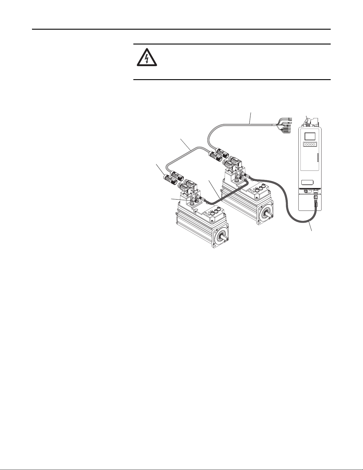
PORT 1 PORT 2 NETWORK
IDM-to-IDM Hybrid Cable
(2090-CHBP8S8-12AAxx)
IPIM Module
(2094-SEPM-B24-S)
IDM Unit
(MDF-SBxxxx)
Network Terminator
Last IDM Unit
(2090-CTSRP)
Network Cable
(2090-CNSxPxS)
Network Cable to
First IDM Unit
(2090-CNSSPxS)
Ter m in at o r
Last IDM Unit
(2090-CTHP8)
IPIM-to-IDM Hybrid Cable
(2090-CHBIFS8-12AAxx)
Catalog numbers are in parenthesis
IDM Unit
(MDF-SBxxxx)
Typical Hardware Configurations
SHOCK HAZARD: To avoid personal injury due to electrical shock, place a
2094-PRF slot-filler module in all empty slots on the power rail.
Any power rail connector without a module installed will disable the 3-phase
power; however, control power is still present.
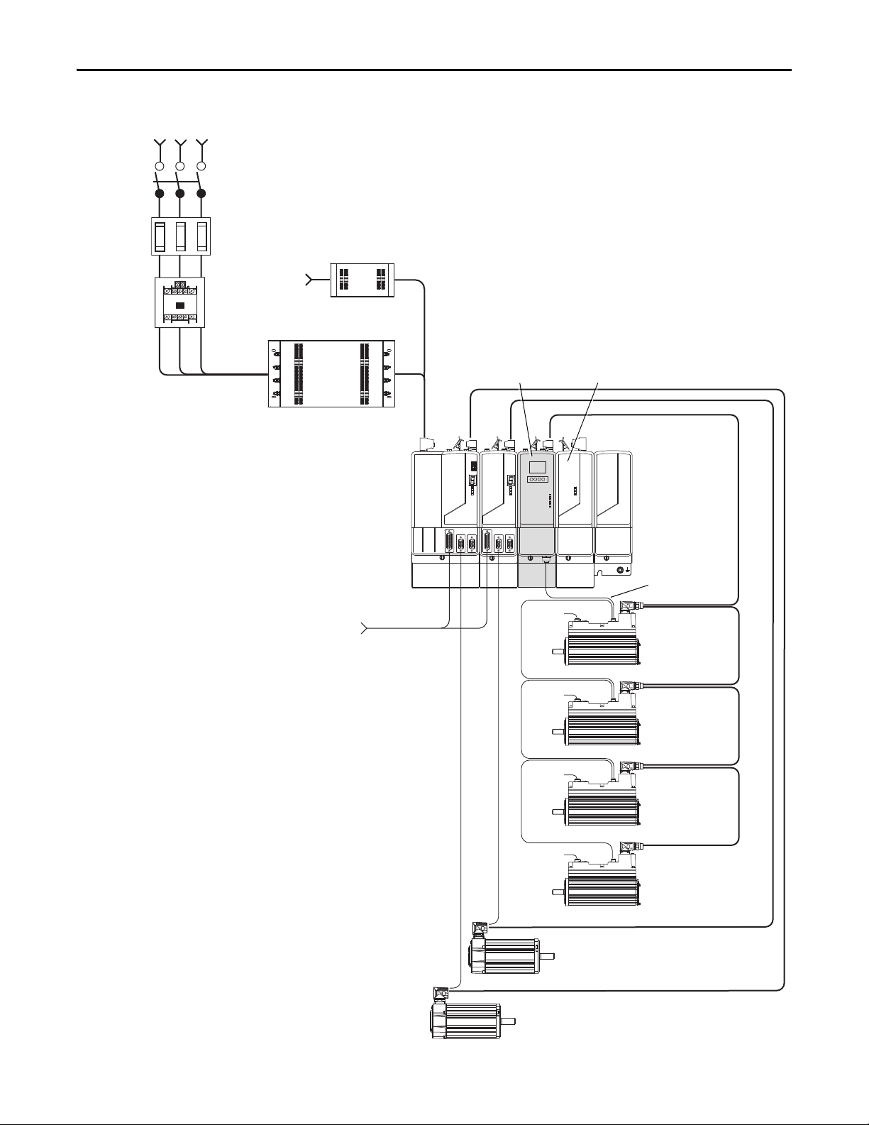
Figure 1 - Typical Kinetix 6000M Integrated Drive-motor System
Rockwell Automation Publication 2094-UM003A-EN-P - May 2012 11
Page 12
Chapter 1 Start
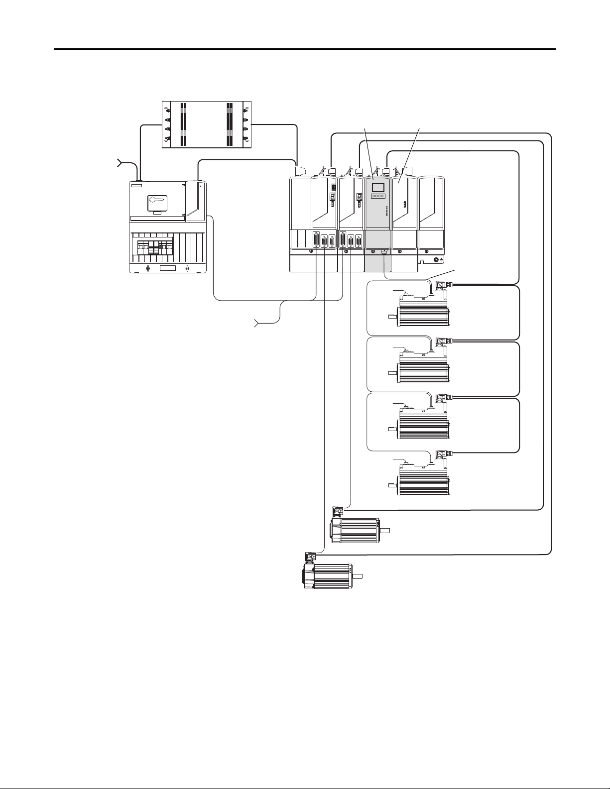
2094-BLxxS
Line Interface Module
(optional component)
3-Phase
Input Power
2094-BSP2
Shunt Module
(optional component)
2090-XXLF-xxxx
AC Lin e Filter
(required for CE)
2094-PRSx
Power Rail
2094-PRF
Slot-filler Module
(required for
unused slots)
To Input Sensors
and Control String
Control Power
2090-K6CK-Dxxxx
Low Profile Connector
Kits for I/O, Motor
Feedback, and Aux
Feedba ck
Bulletin 2090
Motor Feedback Cables
Bulletin 2090
Hybrid Cables
Bulletin 2090
Network Cables
2094-SEPM-B24-S
IPIM Module
Bulletin 2090
Motor Power Cables
MDF-SBxxxxx
IDM Unit
MDF-SBxxxxx
IDM Unit
MDF-SBxxxxx
IDM Unit
MDF-SBxxxxx
IDM Unit
Digital
Inputs
Digital
Inputs
Digital
Inputs
Digital
Inputs
2094 Drive System
(Kinetix 6000 shown)
2090-CTHP8, 2090-CTSRP terminators required on last IDM unit.
Figure 2 - Typical 2094 Power Rail with Kinetix 6000M System (with LIM)
MAIN VAC
12 Rockwell Automation Publication 2094-UM003A-EN-P - May 2012
Page 13
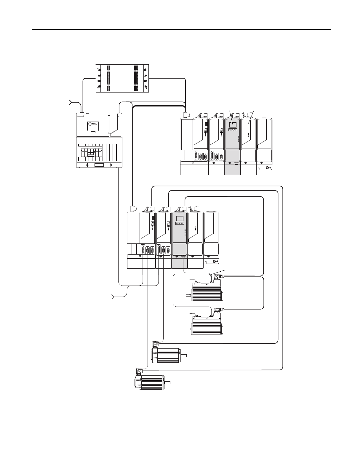
3-Phase Input Power
Line
Disconnect
Device
Input
Fusing
Magnetic
Contactor
2094-BSP2
Shunt Module
(optional component)
2094-PRF
Slot-filler Module
(required for
unused slots)
To Input Sensors
and Control String
Control
Power
2090-K6CK-Dxxxx
Low Profile Connector Kits for I/O,
Motor Feedback, and Aux Feedback
Bulletin 2090
Motor Feedback Cables
2094-SEPM-B24-S
IPIM Module
Bulletin 2090
Motor Power Cables
Digital
Inputs
2090-XXLF-xxxx
AC Lin e Filter
(required for CE)
2090-XXLF-xxxx
Line Filter
(required for CE)
Digital
Inputs
Digital
Inputs
Digital
Inputs
MDF-SBxxxxx
IDM Unit
MDF-SBxxxxx
IDM Unit
MDF-SBxxxxx
IDM Unit
MDF-SBxxxxx
IDM Unit
2094-PRSx
Power Rai l
2094 Drive System
(Kinetix 6000 shown)
Bulletin 2090
Hybrid Cables
Bulletin 2090
Network Cables
2090-CTHP8, 2090-CTSRP terminators required on last IDM unit.
Start Chapter 1
Figure 3 - Typical 2094 Power Rail with Kinetix 6000M System (without LIM)
Rockwell Automation Publication 2094-UM003A-EN-P - May 2012 13
Page 14

Chapter 1 Start
IMPORTANT
In the following example, the leader IAM module is connected to the follower
IAM module via the DC common-bus. When planning your panel layout, you
must calculate the total bus capacitance of your DC common-bus system to be
sure that the leader IAM module is sized sufficiently to pre-charge the entire
system.
Refer to the Kinetix 6000 Multi-axis Servo Drives User Manual, publication
2094-UM001,
Drives User Manual, publication 2094-UM002
or the Kinetix 6200 and Kinetix 6500 Modular Multi-axis Servo
, for further information.
If total bus capacitance of your system exceeds the leader IAM module precharge rating and input power is applied, the IAM module status indicator will
display an error code.
To correct this condition, you must replace the leader IAM module with a larger
module or decrease the total bus capacitance by removing AM or IPIM modules.
14 Rockwell Automation Publication 2094-UM003A-EN-P - May 2012
Page 15
MAIN VAC
3-phase
Input Power
Control Power
2094-BCxx-Mxx-S
IAM Module
Common Bus Leader
2094-PRSx Power R ail
2094-BCxx-Mxx-S
IAM Module
Common Bus Follower
2094-PRF
Slot-filler Module
(required to fill
unused slots)
2094-BLxxS
Line Interface Module
(optional component)
DC Common Bus
2090-XXLF-xxxx
AC Line Filter (required for CE)
2094-BSP2
Shunt Module
(optional component)
To I nput Se nso rs
and Control String
2094-SEPM-B24-S
IPIM Module
Bulletin 2090
Motor Feedback Cables
Bulletin 2090
Motor Power Cables
MDF-SBxxxxx
IDM Unit
MDF-SBxxxxx
IDM Unit
Bulletin 2090
Hybrid Cables
Bulletin 2090
Network Cables
Digital
Inputs
Digital
Inputs
2090-CTHP8, 2090-CTSRP terminators required on last IDM unit.
Start Chapter 1
Figure 4 - Typical Kinetix 6000 with Kinetix 6000M System Common Bus
Rockwell Automation Publication 2094-UM003A-EN-P - May 2012 15
Page 16
Chapter 1 Start
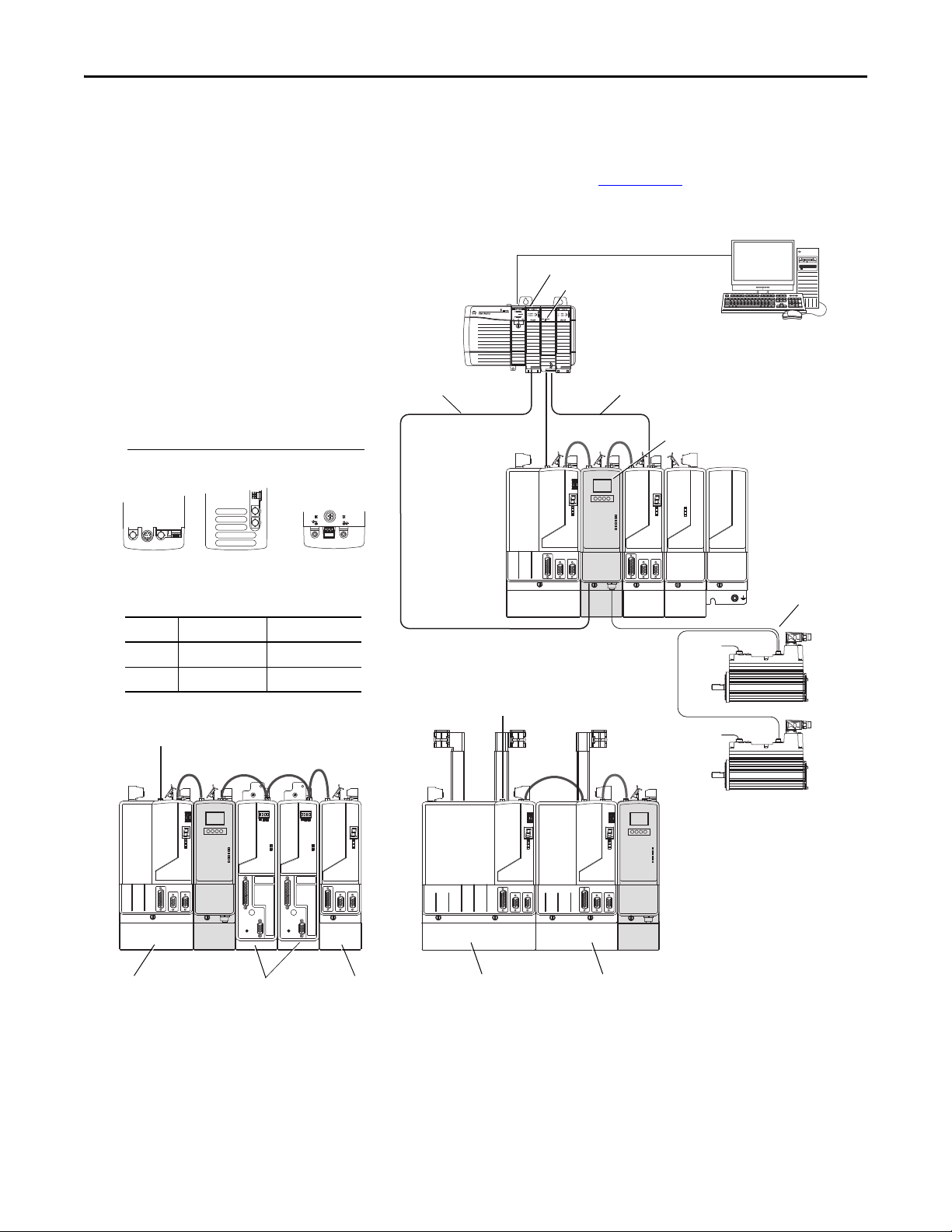
SERCOS interface
Tx (rear)
Rx (front)
OK
CP
TXRX
TX
RX
TXRX
Logix Sercos Interface Module
Logix Platform
(Control Logix is shown)
RSLogix 5000
Software
Bulletin 2090
Sercos Fiber-optic Cable
Logix Controller Programming Network
2094-BCxx-Mxx-S
IAM Module
Single-wide
2094-BCxx-Mxx-S
IAM Module
Kinetix 6000 Double-wide
2094-BCxx-Mxx-S
IAM Module
2094-BMxx-S Double-wide
AM Module
2094-BMxx-S
Single-wide AM
Module
Kinetix 6200
Kinetix 6000
2094-PRSx
Power Rail
2094-SEPM-B24-S
IPIM Module
IPIM Module
Network Connectors (top view)
➋➊➋
➊
➊➋
Recommended Fiber-optic Cables
Number Cable Length Catalog Number
➊ 0.1 m (5.1 in.) 2090-SCxx0-1
➋ 0.2 m (7.1 in.) 2090-SCxx0-2
➊➊
MDF-SBxxxxx
IDM Unit
MDF-SBxxxxx
IDM Unit
Bulletin 2090
Network Cables
Digital
Inputs
Digital
Inputs
EtherNet/IP Module
Bulletin 1585
Ethernet (shielded) Cable
2094-BMxx-M Single-wide
AM Power Modules with
2094-SE02F-M00-Sx
Control Modules
Typical Communication Configurations
The Kinetix 6000M IPIM module uses the EtherNet/IP network to report
diagnostics to the controller and for firmware upgrades via ControlFLASH™
software. For more information on Ethernet cables, refer to the Industrial
Ethernet Media Brochure, publication 1585-BR001
Figure 5 - Typical Kinetix 6000M, Kinetix 6000 and Kinetix 6200 Network Configuration
.
16 Rockwell Automation Publication 2094-UM003A-EN-P - May 2012
Page 17

Start Chapter 1
Catalog Number Explanations
Kinetix 6000M catalog numbers and descriptions are listed in the tables below.
Table 2 - Power Interface Module (IPIM)
Cat. No. Description
2094-SEPM-B24-S 460V IDM Power Interface Module (IPIM) w/Safe-off
Table 3 - Integrated Drive-motor (IDM)
Cat. No. (No Brake) Cat. No. (with Brake) Description
MDF-SB1003P-QJ82A-S MDF-SB1003P-QJ84A-S 460V, IEC 100 mm, 5000 rpm, Keyed
MDF-SB1003P-QK82A-S MDF-SB1003P-QK84A-S 460V, IEC 100 mm, 5000 rpm, Smooth
MDF-SB1153H-QJ82A-S MDF-SB1153H-QJ84A-S 460V, IEC 115 mm, 3500 rpm, Keyed
MDF-SB1153H-QK82A-S MDF-SB1153H-QK84A-S 460V, IEC 115 mm, 3500 rpm, Smooth
MDF-SB1304F-QJ82A-S MDF-SB1304F-QJ84A-S 460V, IEC 130 mm, 3000 rpm, Keyed
MDF-SB1304F-QK82A-S MDF-SB1304F-QK84A-S 460V, IEC 130 mm, 3000 rpm, Smooth
Table 4 - Replacement Parts
Cat. No. Description
Shaft seal kit for:
MPF-SST-A3B3
MPF-SST-A4B4
MPF-SST-A45B45
2094-XNIPIM IPIM module connectors; includes hybrid DC bus,
2094-SEPM-FUSE Fuses for IPIM module, 6 each.
MDF-SB-NODECVR IDM unit node address switch covers.
1485-M12 IDM unit digital input connector covers.
2090-CTHP8
2090-CTSRP
MDF-SB1003
MDF-SB1153
MDF-SB1304
hybrid communication, safe-off, and enable.
Ter m in at o r:
Hybrid
Network
Table 5 - Accessories
Cat. No. Description
MPS-AIR-PURGE Positive air pressure kit.
Rockwell Automation Publication 2094-UM003A-EN-P - May 2012 17
Page 18

Chapter 1 Start
IMPORTANT
IMPORTANT
Component Compatibility
The Kinetix 6000M integrated drive-motor system is compatible with:
• 400V-class Series B Kinetix 6000 drive systems
• 400V-class Kinetix 6200 drive systems
Kinetix 6500 EtherNet/IP control modules (catalog numbers 2094-EN02DM01-Sx) are not compatible with the Kinetix 6000M IPIM or Kinetix 6000/
Kinetix 6200 IAM and AM modules on the same Bulletin 2094 power rail.
The IDM system cannot be accessed with DriveExplorer™ or a human interface
module (HIM). However, all IDM units will respond to a Stop command from a
HIM.
Table 6 - IDM System Compatibility
Component Requires
RSLinx® software version RSLinx version 2.59 or greater will fully support the IPIM
RSLogix™ 5000 software 20.01
IPIM AOP (Add-On Profile) 1.x
Kinetix 6000 drive firmware 1.123 or later
Kinetix 6200 drive firmware 1.045 or later
ControlLogix EtherNet/IP modules All 1756 Ethernet modules; 1756-ENBT, 1756-EN2T
module after installation of an appropriate EDS file
(1)
or later
(1) Version 20.00 may be used if the motion database is updated to version 8.12. For detailed information about updating the motion
database, refer to RA Knowledgebase
article 490160.
18 Rockwell Automation Publication 2094-UM003A-EN-P - May 2012
Page 19

Start Chapter 1
Agency Compliance
If this product is installed within the European Union and has the CE mark, the
following regulations apply.
ATT EN TI ON : Meeting CE requires a grounded system, and the method of
grounding the AC line filter and IDM must match. Failure to do this renders the
filter ineffective and may cause damage to the filter.
Refer to Grounding the IDM System
For more information on electrical noise reduction, refer to the System Design
for Control of Electrical Noise Reference Manual, publication GMC-RM001
on page 54.
.
CE Requirements (system without LIM module)
To meet CE requirements when your system does not include the LIM module,
these requirements apply:
• Install an AC line filter (catalog number 2090-XXLF-xxxx) as close to the
IAM module as possible.
• Use line filters for 3-phase input power and single-phase control power.
• Use 2090 series cables.
• Use 889 series sensor cables.
• Combined motor power cable length for all axes on the same power rail
must not exceed 240 m (787 ft).
• Combined cable length for all IDM units connected to a single IPIM
module is 100 m (328 ft).
• Install the Kinetix 6x00 system inside an enclosure. Run input power
wiring in conduit (grounded to the enclosure) outside of the enclosure.
Separate signal and power cables.
Refer to the Kinetix 6000 Multi-axis Servo Drives User Manual, publication
2094-UM001
Drives User Manual, publication 2094-UM002
including input power wiring.
, or the Kinetix 6200 and Kinetix 6500 Modular Multi-axis Servo
, for interconnect diagrams,
CE Requirements (system with LIM module)
To meet CE requirements when your system includes the LIM module, follow all
the requirements as stated in CE Requirements (system without LIM module)
and these additional requirements as they apply to the AC line filter.
• Install the LIM module (catalog numbers 2094-BL02) as close to the IAM
module as possible.
• Install the LIM module (catalog numbers 2094-BLxxS, or 2094-XL75S-
Cx) with line filter (catalog number 2090-XXLF-xxxx) as close to the
IAM module as possible.
When the LIM module (catalog numbers 2094-BLxxS, or 2094-XL75SCx) supports two IAM modules, each IAM module requires an AC line
filter installed as close to the IAM module as possible.
Rockwell Automation Publication 2094-UM003A-EN-P - May 2012 19
Page 20

Chapter 1 Start
Notes:
20 Rockwell Automation Publication 2094-UM003A-EN-P - May 2012
Page 21
Chapter 2
Planning the Kinetix 6000M System Installation
This chapter describes system installation guidelines used in preparation for
mounting your Kinetix 6000M components.
Top ic Pag e
Cable Length Restrictions and System Sizing 21
IPIM Module Design Guidelines 22
IDM Unit Design Guidelines 26
Electrical Noise Reduction 27
ATT EN TI ON : Plan the installation of your system so that you can perform all
cutting, drilling, tapping, and welding with the system removed from the
enclosure. Because the system is of the open type construction, be careful to
keep any metal debris from falling into it. Metal debris or other foreign matter
can become lodged in the circuitry, which can result in damage to components.
Cable Length Restrictions and System Sizing
This section provides guidelines for sizing an IDM system. For accurate, detailed
sizing, use Motion Analyzer software version 6.000 or later. For additional
information and a sizing estimation method, refer to Kinetix 6000M System
Sizing on page 127.
When sizing your system, please note the following:
• Motion Analyzer software (version 6.000 or later), should be used for
sizing your system.
• Maximum cable length between IDM units is 25 m (82 ft).
• Combined cable length for all IDM units connected to a single IPIM
module is 100 m (328 ft).
• Combined motor power and hybrid cable length for all axes on the same
power rail must not exceed 240 m (787 ft).
• The number of IDM units also depends on the use of the safe-off function.
Refer to Using the Safe Torque-off Feature with the Kinetix 6000M
System on page 103 for details.
Rockwell Automation Publication 2094-UM003A-EN-P - May 2012 21
Page 22

Chapter 2 Planning the Kinetix 6000M System Installation
IMPORTANT
The following items limit the number of IDM units that can be used in a system.
1. The IDM unit control power load which consists of three load sources:
• internal load (constant)
• parking brake load
• digital input loading.
These items also affect the total control power load:
• The cable lengths between IDM units
• IDM units with brakes and their location in the daisy chain
• IDM units that use digital inputs.
2. The continuous and intermittent load on the DC bus of all AM modules
and IDM units.
The Kinetix 6000 or Kinetix 6200 IAM module supplying DC bus power to the
IDM units should be sized to support all IDM units connected to the power rail.
Motion Analyzer software (version 6.000 or later) sizing analysis accounts for
control power and DC bus power.
IPIM Module Design Guidelines
3. The total number of axes connected in the safe-off circuit.
Use the information in this section when designing your enclosure and planning
to mount your system components.
For on-line product selection and system configuration tools, including
AutoCAD (DXF) drawings of the product, refer to
http://www.rockwellautomation.com/en/e-tools
.
System Mounting Requirements
• To comply with UL and CE requirements, the Kinetix 6000M power
interface module must be part of a Kinetix 6000 or Kinetix 6200 system
that is enclosed in a grounded conductive enclosure offering protection as
defined in standard EN 60529 (IEC 529) to IP2X such that they are not
accessible to an operator or unskilled person. A NEMA 4X enclosure
exceeds these requirements providing protection to IP66.
• The panel you install inside the enclosure for mounting your system
components must be on a flat, rigid, vertical surface that won’t be subjected
to shock, vibration, moisture, oil mist, dust, or corrosive vapors.
• Size the enclosure so as not to exceed the maximum ambient temperature
rating. Consider heat dissipation specifications for all components.
• Use high-frequency (HF) bonding techniques to connect the modules,
enclosure, machine frame, and motor housing, and to provide a lowimpedance return path for high-frequency (HF) energy and reduce
electrical noise.
22 Rockwell Automation Publication 2094-UM003A-EN-P - May 2012
Page 23

Planning the Kinetix 6000M System Installation Chapter 2
IMPORTANT
• Combined motor power cable lengths for all axes and hybrid cable lengths
for all IDM units on the same DC bus must not exceed 240 m (787 ft)
with 400V-class systems. Drive-to-motor power cables must not exceed
90 m (295.5 ft).
System performance was tested at these cable length specifications. These
limitations also apply when meeting CE requirements.
Refer to the System Design for Control of Electrical Noise Reference Manual,
publication GMC-RM001
reduction.
, to better understand the concept of electrical noise
Circuit Breaker/Fuse Options
The 2094-SEPM-B24-S IPIM module and the MDF-SBxxxxx IDM units use
internal solid-state motor short-circuit protection and when protected by
suitable branch circuit protection, are rated for use on a circuit capable of
delivering up to 200,000 A. Fuses or circuit breakers, with adequate withstand
and interrupt ratings, as defined in NEC or applicable local codes, are permitted.
The 2094-BL02 LIM module contains supplementary protection devices and,
when protected by suitable branch circuit protection, are rated for use on a
circuit capable of delivering up to 5000 A. When these modules are used,
protection on the line side of the LIM module is required. Fuses must be class J or
CC only.
The 2094-BLxxS, and 2094-XL75S-Cx LIM modules contain branch circuit
rated devices suitable for use on a circuit capable of delivering up to 65,000 A
(400V-class).
Refer to the Line Interface Module Installation Instructions, publication 2094-
IN005, for power specifications and more information on using the LIM
module.
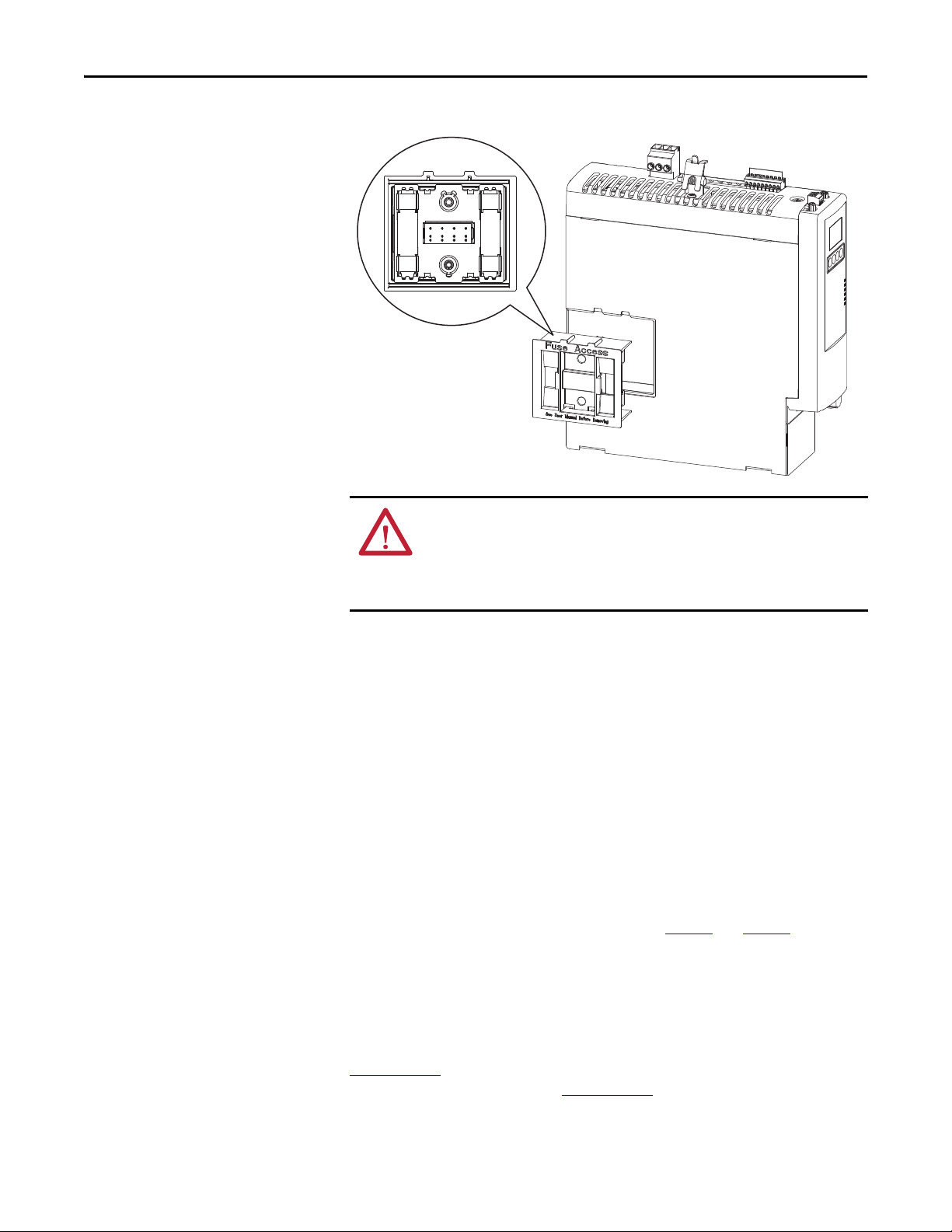
Fuse Location and Replacement
The IPIM module uses internal fuses (see Figure 6) for short-circuit protection
of the DC bus. The recommended fuse is Bussmann FWP-50A14Fa. A fuse
replacement kit (catalog number 2094-SEPM-FUSE) is also available.
Rockwell Automation Publication 2094-UM003A-EN-P - May 2012 23
Page 24
Chapter 2 Planning the Kinetix 6000M System Installation
Figure 6 - IPIM Fuse Location
ATT EN TI ON : Capacitors on the DC bus may retain hazardous voltages after
input power has been removed. Before working on the IDM system, measure
the DC bus voltage to verify it has reached a safe level or wait the full time
interval as indicated in the warning on the IPIM module. Failure to observe this
precaution could result in severe bodily injury or loss of life.
To replace the fuses, follow these steps.
1. Ensure that all power to the power rail has been removed.
2. Measure the DC bus voltage to verify it has reached a safe level or wait the
full time interval as indicated in the warning on the IPIM module.
3. Loosen the captive screws.
4. Grasp the top and bottom edges of the fuse holder and pull straight out.
5. Replace the fuses.
Enclosure Selection
Heat dissipation of the IPIM module is shown in Ta b l e 7 and Ta b l e 8 . To size the
enclosure you will need heat dissipation data from all equipment inside the
enclosure (such as the Logix controller, LIM module, IAM). Once the total
amount of heat dissipation (in watts) is known, you can calculate the minimum
enclosure size.
Refer to the Kinetix 6000 Multi-axis Servo Drives User Manual, publication
2094-UM001
, or the Kinetix 6200 and Kinetix 6500 Modular Multi-axis Servo
Drives User Manual, publication 2094-UM002
24 Rockwell Automation Publication 2094-UM003A-EN-P - May 2012
, for further information.
Page 25

Planning the Kinetix 6000M System Installation Chapter 2
Table 7 - Power Dissipation Specifications - Percent of DC Bus Current
Power Dissipation as % of DC Bus Current Output Rating
Watts
20% 40% 60% 80% 100%
2 7 142538Y = 33.95x2 + 3.18x
(1) x is percent of DC bus current output rating: any value between 0.0 and 1.0.
Heat Dissipation Formula
Table 8 - Power Dissipation Specifications - Percent of IPIM Module Control Power
(1)
Power Dissipation as % of IPIM Module Control
Control Power Input
Frequenc yHzVolt age
AC 20% 40% 60% 80% 100%
50
60
(1) x is percent of IPIM module control power output rating: any value between 0.0 and 1.0.
120V 22 29 38 48 61 Y = 23.76x
240V 34 42 52 63 76 Y = 18.56x
120V 23 27 32 39 46 Y = 14.57x2 + 11.40x + 20.01
240V 38 49 62 76 92 Y = 19.63x2 + 43.22x + 28.75
Power Out put Rati ng
Watts
Heat Dissipatio n Formulas
2
+ 20.73x + 16.54
2
+ 30.19x + 27.41
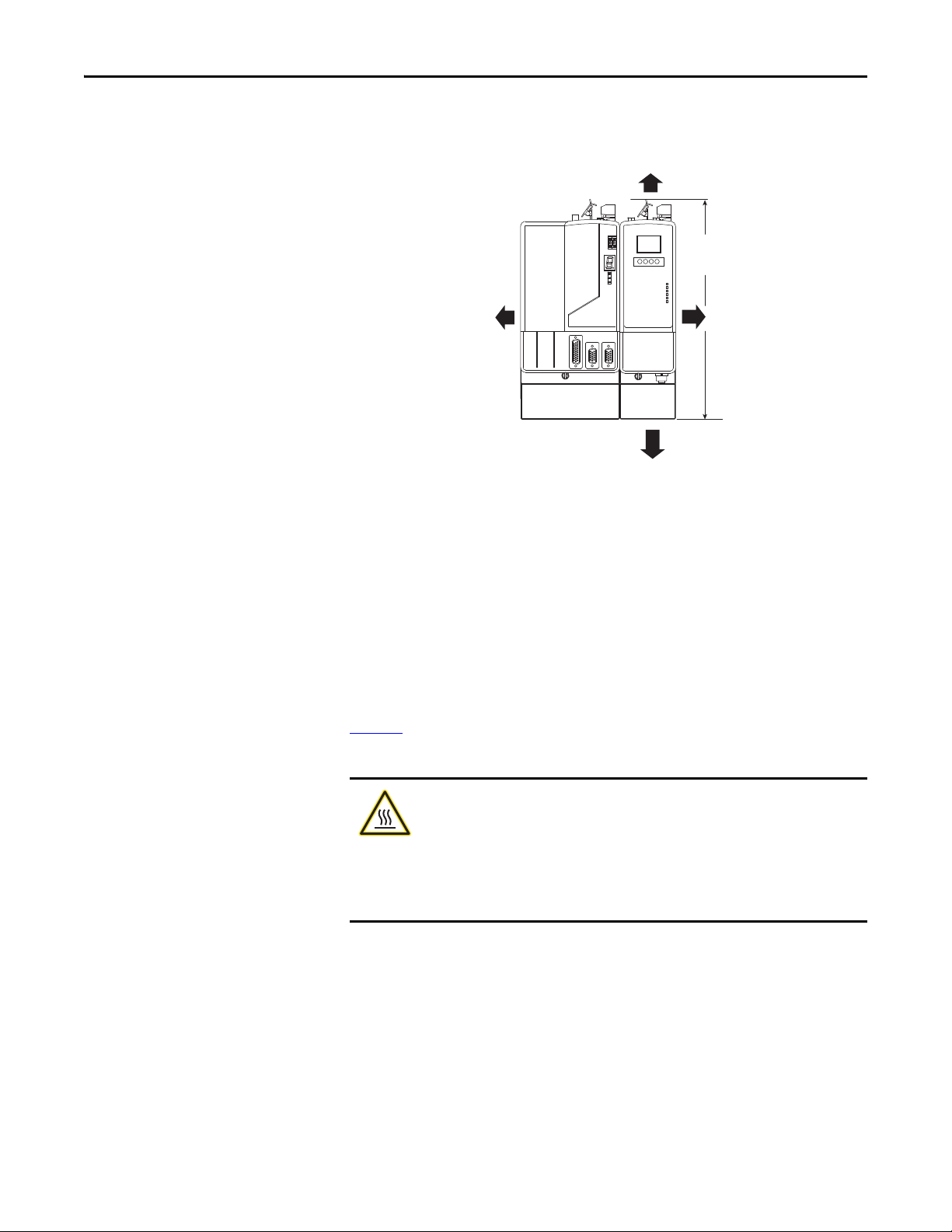
Minimum Clearance Requirements
This section provides information to assist you in sizing your cabinet and
positioning your IDM unit.
Figure 7
installation:
illustrates minimum clearance requirements for proper airflow and
• Additional clearance is required for the cables and wires connected to the
top and front of the module.
• Additional clearance left and right of the power rail is required when the
module is mounted adjacent to noise sensitive equipment or clean
wireways.
(1)
Table 9 - Minimum Cabinet Depth
Cat. No. Cabinet Depth, Min
2094-SEPM-B24-S 272 mm (10.7 in.)
Rockwell Automation Publication 2094-UM003A-EN-P - May 2012 25
Page 26
Chapter 2 Planning the Kinetix 6000M System Installation
Clearance right of the
module is not required
(1)
50.8 mm (2.0 in.) clearance for
airflow and installation
Clearance left of the
module is not required
(1)
Power Rail
(2094-PRSx)
50.8 mm (2.0 in.) clearance for
airflow and installation
(1) The power rail (slim), catalog number 2094-PRSx, extends left and right of the first and last module 5.0 mm (0.20
in.). The Bulletin 2094-PRx power rail extends approximately 25.4 mm (1.0 in.) left of the IAM module and right of
the last module mounted on the rail.
(2) Dimension applies to the following modules:
IPIM module 2094-SEPM-B24-S
IAM module (Series B) 2094- BC01-Mxx-x and 2094-BC02-M02-x
AM module (Series B) 2094-BMP5-x, 2094-BM01-x, 2094-BM02-x
287 mm
(11.3 in.)
(2)
Figure 7 - Minimum IPIM Module Clearance Requirements
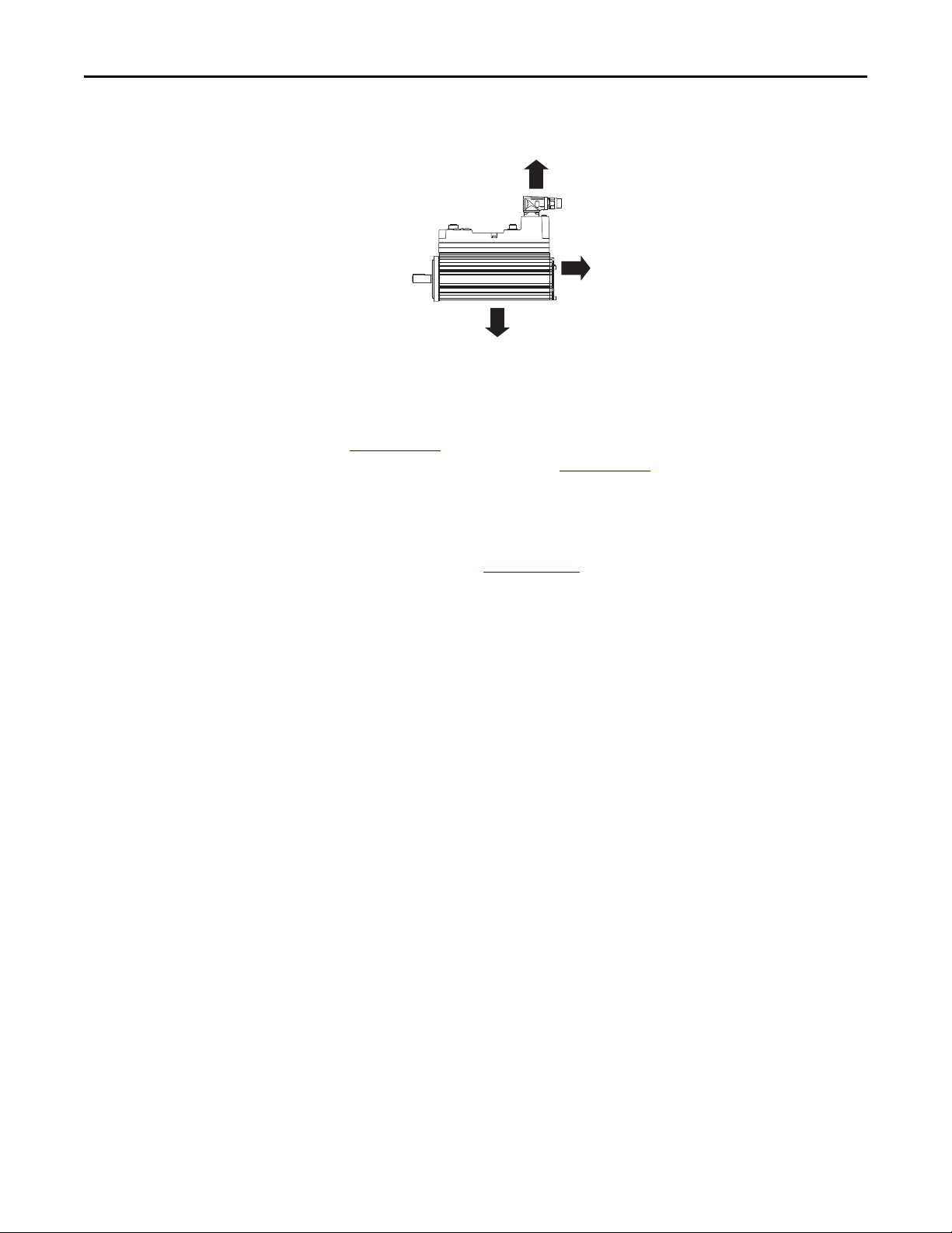
IDM Unit Design Guidelines
Minimum Clearance Requirements
Figure 8 illustrates minimum IDM unit clearance requirements for proper
airflow and installation.
BURN HAZARD: Outer surfaces of the motor can reach high temperatures,
125 °C (275 °F), during motor operation.
Take precautions to prevent accidental contact with hot surfaces. Consider IDM unit
surface temperature when selecting motor mating connections and cables.
Failure to observe these safety procedures could result in personal injury or
damage to equipment.
Additionally, consider the following items:
• Obtain the specified motor thermal rating by mounting the motor on a
surface with heat dissipation equivalent to a 304.8 x 304.8 x 12.7 mm
(12 x 12 x 0.5 in.) aluminum heatsink.
• Do not install the motor in an area with restricted airflow, and keep other
heat producing devices away from the motor.
26 Rockwell Automation Publication 2094-UM003A-EN-P - May 2012
Page 27
Planning the Kinetix 6000M System Installation Chapter 2
100.0 mm (3.9 in.)
100.0 mm (3.9 in.)
100.0 mm (3.9 in.)
Figure 8 - Minimum IDM Unit Clearance Requirements
Electrical Noise Reduction
Refer to the Kinetix 6000 Multi-axis Servo Drives User Manual, publication
2094-UM001
Drives User Manual, publication 2094-UM002
, or the Kinetix 6200 and Kinetix 6500 Modular Multi-axis Servo
, for information on best practices
that minimize the possibility of noise-related failures as they apply specifically to
Kinetix 6000 system installations. For more information on the concept of highfrequency (HF) bonding, the ground plane principle, and electrical noise
reduction, refer to the System Design for Control of Electrical Noise Reference
Manual, publication GMC-RM001
.
Observe these guidelines when your system includes the 2094-SEPM-B24-S
IPIM module. In this example, a 2094-BL02 LIM module is used in the Bulletin
2094 system and mounted left of the IAM module:
• Establish clean (C) and dirty zones (D) similar to other Bulletin 2094
drive systems.
• The sercos fiber-optic cables are immune to electrical noise, but due to
their delicate nature, route them in the clean zone.
• IPIM communication wires are noise sensitive and belong with the fiberoptic cables in the clean zone.
• Ethernet cables are noise sensitive and belong in the clean zone.
• IDM network cables, although noise sensitive by nature, are shielded and
designed to be routed with the hybrid cable outside of the enclosure.
• The Bulletin 2090 hybrid cable is dirty and belongs in the dirty zone.
This layout is preferred due to the reduced size of the very dirty zone.
Rockwell Automation Publication 2094-UM003A-EN-P - May 2012 27
Page 28
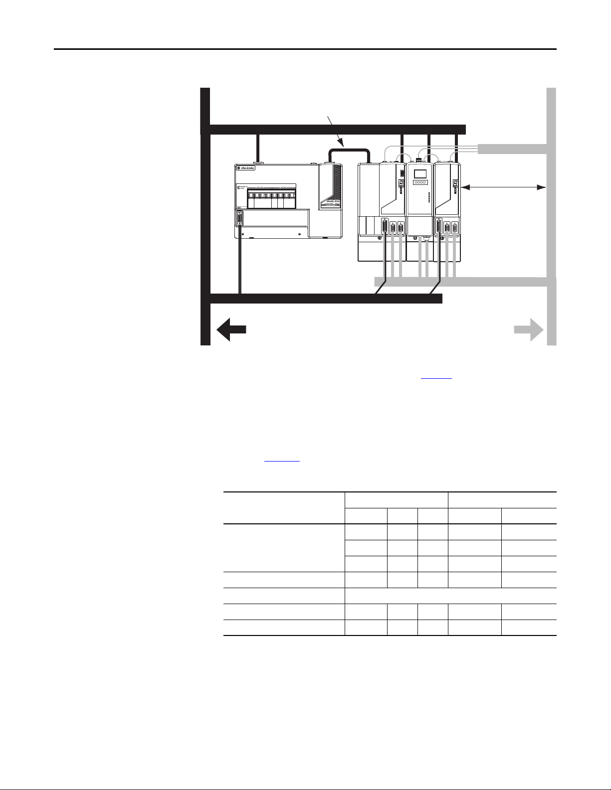
Chapter 2 Planning the Kinetix 6000M System Installation
2094-BL02 or 2094-BLxxS
Line Interface Module
Kinetix 6000
System
Dirty Wireway
Clean Wireway
I/O
(1)
, Feedback, and
Network Cables
Motor and Hybrid Cables
Very Dirty Filter/IAM Connections
Segregated (not in wireway)
Route 24V DC I/O
shielded cable.
Route encoder/analog/registration
shielded cables.
Fiber-optic Cables and
IPIM Communication Wires
No sensitive
(2)
equipment within
150 mm (6.0 in.).
D
Figure 9 - Noise Zones (Bulletin 2094 power rail with IPIM module)
D
D
(1) If drive system I/O cable contains (dirty) relay wires, route cable with LIM module I/O c able in dirty wireway.
(2) When space does not permit the 150 mm (6.0 in.) segregation, use a grounded steel shield instead. For examples, refer to the
System Design for Control of Electrical Noise Reference Manual, publication GMC-RM001
VD
D
D
CC
.
Cable Categories for Kinetix 6000M System
C
Zoning requirements of cables connecting to the IDM system components are
shown in Ta b l e 1 0
Table 10 - IPIM Module Zoning Requirements
Wire/Cable
Hybrid DC bus power, control power,
inter-module communication, and safe-
(1)
off
Enable input X X
Fiber-optic No restrictions
Ethernet network X X
IDM network
(1) There is no option for making your own hybrid or IDM network cables.
(1)
.
Zone Method
Very Dirty Dirty Clean Ferrite Sleeve Shielded Cable
XX
XX
X
XX
28 Rockwell Automation Publication 2094-UM003A-EN-P - May 2012
Page 29
Chapter 3
Mounting the Kinetix 6000M System
This chapter provides the system installation procedures for mounting your
Kinetix 6000M integrated drive-motor (IDM) unit and your power interface
module (IPIM).
Top ic Pa ge
Mounting the IPIM Module 30
Installing the IDM Unit 33
This procedure assumes you have prepared your panel, mounted your Bulletin
2094 power rail, and understand how to bond your system. For installation
instructions regarding equipment and accessories not included here, refer to the
instructions that came with those products.
SHOCK HAZARD: To avoid hazard of electrical shock, perform all mounting and
wiring of the Bulletin 2094 power rail and modules prior to applying power.
Once power is applied, connector terminals may have voltage present even
when not in use.
ATT EN TI ON : Plan the installation of your system so that you can perform all
cutting, drilling, tapping, and welding with the system removed from the
enclosure. Because the system is of the open type construction, be careful to
keep any metal debris from falling into it. Metal debris or other foreign matter
can become lodged in the circuitry, which can result in damage to components.
Rockwell Automation Publication 2094-UM003A-EN-P - May 2012 29
Page 30
Chapter 3 Mounting the Kinetix 6000M System
Mounting the IPIM Module
Using the 2094 Mounting Brackets
You can use Bulletin 2094 mounting brackets to mount the power rail or LIM
module over the AC line filter. Refer to the 2094 Mounting Brackets Installation
Instructions, publication 2094-IN008
, when using mounting brackets with your
system.
Installing the 2094 Power Rail
The Bulletin 2094 power rail comes in lengths to support one IAM module and
up to seven additional modules. A maximum of four IPIM modules can be
mounted to a single power rail. The connector pins for each slot are covered by a
protective cover. The cover is designed to protect the pins from damage and make
sure that no foreign objects lodge between the pins during installation. Refer to
the Kinetix 6000 Power Rail Installation Instructions, publication 2094-IN003
when installing your power rail.
ATT EN TI ON : To avoid damage to the power rail during installation, do not
remove the protective covers until the module for each slot is ready for
mounting.
,
Determine Mounting Order
Refer to the Module Mounting Order Example diagram on page 31 and mount
the modules in the order (left to right) shown. Install modules according to
power utilization (highest to lowest) from left to right starting with the highest
power utilization. If power utilization is unknown, position modules (highest to
lowest) from left to right based on the IPIM or AM continuous power rating
(kW).
Power utilization is the average power (kW) consumed by a servo axis. If the
servo axis has been sized by using Motion Analyzer software, version 6.000 or
later, the calculated axis power required can be used for power utilization. If the
servo axis has not been sized in Motion Analyzer, use Ta b l e 1 1
maximum continuous power for IPIM and AM modules, to determine the
desired location on a power rail.
Table 11 - Module Type and Continuous Power Output
2094-BM05-S
Axis Module
22.0 kW 15.0 kW 13.5 kW 6.6 kW 3.9 kW 1.8 kW
2094-SEPM-B24-S
IPIM Module
2094-BM03-S
Axis Module
2094-BM02-S
Axis Module
The IPIM module may be installed on a power rail with an IAM module
configured as a common bus follower, but you will be responsible for configuring
the leader for the appropriate additional capacitance in the follower power rail,
including the IPIM module.
, showing the
2094-BM01-S
Axis Module
2094-BMP5-S
Axis Module
30 Rockwell Automation Publication 2094-UM003A-EN-P - May 2012
Page 31

Figure 10 - Module Mounting Order Example
IMPORTANT
Highest Power Utilization Lowest Power Utilization
Integrated Axis
Module
Shunt
Module
Slot Filler
Module
IPIM Module Axis Modules
The IAM must be positioned in the leftmost slot of the power rail. Position your
other modules to the right of the IAM module.
Mount modules according to power utilization (highest to lowest) from left to
right starting with the highest power utilization. If power utilization is
unknown, position modules (highest to lowest) from left to right based on
continuous power rating (kW). Refer to page 30
The shunt module must be installed to the right of the last module. Only slotfiller modules may be installed to the right of the shunt module.
Do not mount the shunt module on power rails with a follower IAM module.
Common bus follower IAM modules disable the internal, rail mounted, and
external shunt modules.
Mounting the Kinetix 6000M System Chapter 3
.
Rockwell Automation Publication 2094-UM003A-EN-P - May 2012 31
SHOCK HAZARD: To avoid personal injury due to electrical shock, place a
2094-PRF slot-filler module in all empty slots on the power rail. Any power rail
connector without a module installed will disable the drive system; however,
control power will still be present.
Page 32

Chapter 3 Mounting the Kinetix 6000M System
Slots for Additional Modules
Power Rail Sl ot
Mounting Bracket
Power Rail
Fuse Access
See User Manual Before Removing
Guide Pin Hole
Rear View
Side View
Power Rai l
Guide Pin
Pivot module
downward and align
with pin
Mount the IPIM Module
All modules mount to the power rail using the same technique.
1. Determine the next available slot and module for mounting. Refer to
Determine Mounting Order
2. Remove the protective covers from the power rail connectors.
3. Inspect the module connector pins and power rail connectors and remove
any foreign objects.
ATTENTION: To avoid damage to the pins located on the back of each
module and to make sure that module pins mate properly with the
power rail, hang modules as explained below.
The power rail must be mounted vertically on the panel before hanging
modules on the power rail.
4. Hang the module mounting bracket from the slot on the power rail.
on page 30.
5. Pivot module downward and align the guide pin on the power rail with the
guide pin hole in the back of the module.
6. Gently push the module against the power rail connectors and into the
32 Rockwell Automation Publication 2094-UM003A-EN-P - May 2012
final mounting position.
Page 33

Mounting the Kinetix 6000M System Chapter 3
Power Rail
Bracket secured in slot
Flat
2.26 N•m (20 lb•in)
7. Tighten the mounting screws.
8. Repeat the above steps for each module being installed.
Installing the IDM Unit
ATT EN TI ON : Do not attempt to open or modify the IDM unit. This manual
describes modifications that you can perform in the field. Do not attempt other
changes. Only a qualified Allen-Bradley employee can service an IDM unit.
Failure to observe these safety procedures could result in personal injury or
damage to equipment.
ATT EN TI ON : Damage may occur to the bearings and the feedback device if a
sharp impact is applied to the shaft during installation of couplings and pulleys,
or to remove the shaft key. Damage to the feedback device also may result from
applying leverage from the faceplate to remove devices mounted on the shaft.
Do not strike the shaft, key, couplings, or pulleys with tools during installation or
removal. Use a wheel puller to apply pressure from the user end of the shaft to
remove any friction fit or stuck device from the shaft.
Failure to observe these safety procedures could result in damage to the IDM unit.
Rockwell Automation Publication 2094-UM003A-EN-P - May 2012 33
Page 34

Chapter 3 Mounting the Kinetix 6000M System
Aligning the IDM Unit
The IDM unit can be mounted in any position and has a mounting pilot that aids
in aligning the unit on a machine. A shaft seal that helps protect the motor
against fine dust and fluids is factory installed and should be replaced at regular
intervals.
Preferred fasteners are stainless steel. The installation must comply with all local
regulations. The installer also must use equipment and installation practices that
promote electromagnetic compatibility and safety.
ATT EN TI ON : Unmounted IDM units, disconnected mechanical couplings, loose
shaft keys, and disconnected cables are dangerous, if power is applied.
Disassembled equipment should be appropriately identified (tagged-out) and
access to electrical power restricted (locked-out).
Before applying power, remove the shaft key and other mechanical couplings that
could be thrown from the shaft.
Failure to observe these safety procedures could result in personal injury or
damage to equipment.
Mount and Connect the IDM Unit
To install the IDM unit, follow these procedures and recommendations.
ATT EN TI ON : Arcing or unexpected motion can occur if cables are connected or
disconnected while power is applied to the IDM system. Before working on the
system, disconnect power and wait the full time interval indicated on the IPIM
module warning label or verify the DC bus voltage at the IPIM module measures
less than 50V DC.
Failure to observe this precaution could result in severe bodily injury or loss of life,
and damage to the product will occur.
ATT EN TI ON : Do not strike the shaft, couplings, or pulleys with tools during
installation or removal.
Damage may occur to the motor bearings and the feedback device if you apply a
sharp impact to the shaft during installation of couplings and pulleys, or a shaft
key.
Failure to observe these safety procedures could result in damage to the motor and
its components.
ATT EN TI ON : The IDM unit is not for direct connection to an AC power line.
IDM units are designed for connection to an IPIM module that controls the
application of power.
Failure to observe these safety precautions could result in damage to the motor
and equipment.
34 Rockwell Automation Publication 2094-UM003A-EN-P - May 2012
Page 35

Mounting the Kinetix 6000M System Chapter 3
TIP
1. Allow sufficient clearances around the IDM unit for it to stay within its
specified operating temperature range. See page 27
for details.
BURN HAZARD: Outer surfaces of the IDM unit can reach high temperatures,
125 °C (275 °F), during motor operation.
Take precautions to prevent accidental contact with hot surfaces. Consider IDM
unit surface temperature when selecting motor mating connections and cables.
Failure to observe these safety procedures could result in personal injury or
damage to equipment.
2. Determine the radial and axial shaft load limitations of your motor. Refer
to the Kinetix Rotary Motion Specifications Technical Data, publication
GMC-TD001
, for specifications.
3. Set the node address for the IDM unit. Refer to Setting the Node Address
on page 70
.
4. If sufficient mounting clearance is provided, rotate the hybrid cable
connectors into position prior to installing. If the mounting clearance is
restricted, rotate after installing.
ATT EN TI ON : Connectors are designed to be rotated into a fixed position during
motor installation, and remain in that position without further adjustment.
Strictly limit the applied forces and the number of times the connector is
rotated to make sure that connectors meet the specified IP ratings.
Apply force only to the connector and cable plug. Do not apply force to the cable
extending from the cable plug. No tools, for example pliers or vise-grips, should be
used to assist with the rotation of the connector.
Failure to observe safety precautions could result in damage to the IDM unit and its
components.
5. Position the IDM unit on the machine in any position.
IDM units with a brake may require use of the manual brake release
cable to release the brake prior to rotating the shaft so the IDM unit
will align with the machine mounts.
Refer to the Manual Brake Release Cable Installation Instructions,
publication 2090-IN037
, for details on using this cable.
6. Properly mount and align the IDM unit using stainless steel bolts. Refer to
the Kinetix Rotary Motion Specifications Technical Data, publication
GMC-TD001
Rockwell Automation Publication 2094-UM003A-EN-P - May 2012 35
, for dimensions.
Page 36

Chapter 3 Mounting the Kinetix 6000M System
Notes:
36 Rockwell Automation Publication 2094-UM003A-EN-P - May 2012
Page 37

Chapter 4
Kinetix 6000M System Connector Data
This chapter provides connector locations and signal descriptions for your
Kinetix 6000M integrated drive-motor system.
Top ic Pa ge
IPIM Module Connectors and Indicators 38
IPIM Module Connector and Signal Descriptions 39
IDM Unit Connectors and Indicators 43
IDM Unit Connector and Signal Descriptions 44
Power Specifications 50
Feedback Specifications 52
Rockwell Automation Publication 2094-UM003A-EN-P - May 2012 37
Page 38

Chapter 4 Kinetix 6000M System Connector Data
➋
➊
➌
➏
➍
➎
➒
➑
➐
➓
IPIM Module Connectors and Indicators
Figure 11 - Module Connectors and Indicators
SH1
42+
42-
SH2
CN-
CN+
OUT
RTN
SH3
SE1
SE-
SE2
ETHERNET 1
ETHERNET 2
NETWORK
Item Description See page
➊ Hybrid cable DC bus connector Termination point for +/- DC and PE 39
➋ Hybrid cable communication signals
connector
Connection point for IDM unit power and
communication
39
➌ Safe- off connector Termination point for safety signals 40
➍ Enable connector Enable input to the IDM system 41
➎ Sercos fiber-optic connectors Transmit and receive fiber-optic connectors 41
➏ LCD display Allows ethernet configuration and system status 66
➐ Navigation buttons Four buttons provide access and navigation
66
when using the LCD display
➑ Status indicators
DC Bus
Control Bu s
Port 1 and Port 2
Module Status
Network Status
DC bus status
Control bus status (present, faulted)
Communication status of the EtherNet/IP ports
IPIM module status (operating, standby, faulted)
Indicates IDM system network status
90
➒ EtherNet/IP ports Two Ethernet ports are provided 42
➓ IDM network cable connector Connection point for network cable to first IDM
42
unit
38 Rockwell Automation Publication 2094-UM003A-EN-P - May 2012
Page 39

Kinetix 6000M System Connector Data Chapter 4
1
DC-
DC+
IPIM Module Connector and Signal Descriptions
Hybrid Cable DC Bus Connector
This connector supplies the DC bus voltage. Three wires from the
hybrid power and communication cable (catalog number 2090CHBIFS8-12AAxx) are used to extend this voltage to the first
IDM unit.
Strip
Length
Terminal Description Signal
1 DC bus supply (-) DC- DC- 9.7 (0.38) 0.75 (6.6)
2 Chassis ground
3 DC bus supply (+) DC+ DC+
Hybrid Cable Communication Signals Connector
mm (in.)
1
SH1
The hybrid communication connector extends control
power, communication, and safety signals to the first
IDM unit. The 2090-CHBIFS8-12AAxx cable
interfaces with this connector.
42+
42-
SH2
Tor que
N•m (lb•in)
CN-
CN+
OUT
RTN
SH3
SE1
SE-
SE2
Strip
Length
Terminal Description Signal
1 Shield – SH1 6.4 (0.25) 0.235 (2.0)
2 Control Power +42V DC 42V + 42+
3 Control Power -42V DC 42V COM 424 CAN Bus Shield IDM CAN SHIELD SH2
5 IDM CAN Bus Lo IDM CAN LO CN6 IDM CAN Bus Hi IDM CAN HI CN+
7 System OK out to IDMs IDM SYSOKOUT OUT
8 System OK return from IDMs IDM SYSOKRTN RTN
9 Safety Shield SAFETY SHIELD SH3
10 Safety Enable Input 1 SAFETY ENABLE 1+ SE1
11 Safety Enable Common SAFETY ENABLE- SE12 Safety Enable Input 2 SAFETY ENABLE 2+ SE2
mm (in.)
Tor que
N•m (lb•in)
Rockwell Automation Publication 2094-UM003A-EN-P - May 2012 39
Page 40

Chapter 4 Kinetix 6000M System Connector Data
IMPORTANT
IMPORTANT
Remove the motionallowed jumper before
connecting any safety
devices.
Wiring P lug Hea der
Safe Torque-off Connector
This connector provides a termination
point for connecting safety devices such
as: emergency stop switches, light
1
F2+
F2-
F1+
F1-
SE2
SE-
SE1
24+
24-
curtains, and floor mats. The redundant
safety device outputs should be connected
to Safety Enable Input 1 and 2 with
reference to Safety Enable Common.
Each IPIM module ships with the wiring-plug header and motion-allowed
jumper installed in the safe torque-off connector.
With the motion-allowed jumper installed, the safe torque-off function is
.
defeated
Pins 8 and 9 (24V+) are used only by the motion-allowed jumper. When
wiring to the wiring-plug header, the 24V supply (for an external safety
device that triggers the safe torque-off request) must come from an
external source, otherwise system performance will be jeopardized.
This connector extends the safe-off signals for use in wiring single and multiple
safe torque-off configurations, or to bypass (not use) the safe torque-off function.
Refer to page 107
for further information.
Strip
Length
Terminal Description Signal
(2)
24+
24V COM
(1)
(1)
(1)
(1)
(2)
1 Feedback Monitoring 2+ FDBK2+
2 Feedback Monitoring 2- FDBK23 Feedback Monitoring 1+ FDBK1+
4 Feedback Monitoring 1- FDBK15 Safety Enable Input 2 SAFETY ENABLE 2+ SE2
6 Safety Enable Common SAFETY ENABLE- SE7 Safety Enable Input 1 SAFETY ENABLE 1+ SE1
8 Safety Bypass S upply, +24V
DC, 320 mA max
9 Safety Bypass supply,
Common
(1) Feedback monitoring terminals are provided for compatibility with the Kinetix 6000 safety connector only.
(2) Refer to page 107 for information on the proper use of these terminals.
(3) Maximum/minimum that the connector will accept—these are not recommendations.
mm (in.)
F2+ 7.0
(0.275)
F2F1+
F1-
24+
24-
Tor que
N•m (lb•in)
0.235 (2.0) 0.14…1.5
Min/Max
Wire Size
mm2 (AWG)
(30…14)
(3)
40 Rockwell Automation Publication 2094-UM003A-EN-P - May 2012
Page 41

Kinetix 6000M System Connector Data Chapter 4
TransmitReceive
Sercos Fiber-optic Connectors
The sercos fiber-optic ring is connected by using
the sercos receive (RX) and transmit (TX)
connectors.
ATT EN TI ON : To avoid damage to the sercos RX and TX connectors use only
finger-tight torque when attaching the fiber-optic cables. Do not use a wrench
or any other mechanical assistance. For more information, refer to Fiber-optic
Cable Installation and Handling Instructions, publication 2090-IN010
Table 12 - Sercos Specifications
Attribute Value
Data rates 8 Mbps (fixed)
Light intensity Adjustable, low or high power, selectable via the keypad/LCD display (see page 68
Cyclic update period 500 μs, minimum
Node addresses Assigned on each IDM unit, see page 70
since it is not a sercos device.
. The IPIM module does not have a sercos address
.
).
Enable Input
One digital input is supplied to enable all connected IDM units.
The enable status is transmitted to all of the IDM units.
Strip
Length
Terminal Description Signal
1 +24V DC Enable Supply ENABLE 24V+ + 7.0
2 Enable Input ENABLE INPUT EN
3 24V DC Common ENABLE 24V COM -
(1) Maximum/minimum that the connector will accept—these are not recommendations.
mm (in.)
(0.275)
Table 13 - Enable Input Specifications
Signal Description
ENABLE Optically isolated, single-ended ac tive high signal. Current loading is
nominally 10 mA. A 24V DC input is applied to this terminal to enable all
modules. The reaction time for all IDM units connected to the IPIM is 30 ms,
maximum.
Tor que
N•m (lb•in)
0.235 (2.0) 0.14…1.5
IDM Unit
Reaction
Time
30 ms Level
+
EN
-
Min/Max
Wire Size
mm2 (AWG)
(30…14)
Edge/Level
Sensitive
1
(1)
Rockwell Automation Publication 2094-UM003A-EN-P - May 2012 41
Page 42

Chapter 4 Kinetix 6000M System Connector Data
EtherNet/IP Ports
8-pin Control Module
Ethernet Connector
IDM Network
Connecto r
EtherNet/IP Connectors
Two connectors are provided for firmware upgrades, troubleshooting, and
integration with Logix. The Ethernet ports also support a web browser interface
to provide access to status information for the IPIM module and IDM units.
8
1
Pin Signal Description Signal Name
1 Transmit+ TD+
2 Transmit- TD3Receive+ RD+
4Reserved –
5Reserved –
6Receive- RD7Reserved –
8Reserved –
IPIM Module Network Connector Pinouts
The IDM system network is routed by using 2090-CNSxPxS-AAxx cables. A
2090-CNSSPRS-AAxx or 2090-CNSSPSS-AAxx cable is required for
connection to the IPIM module. The connector type is B-coded M12.
2
5
1
Pin Signal Description Signal Name
1 Transmit (TX+) to IDM unit TX+
2 Return (RX-) from IDM unit RTN RX3 Return (RX+) from IDM unit RTN RX+
4 Transmit (TX-) to IDM unit TX5 Reference signal REF
3
4
42 Rockwell Automation Publication 2094-UM003A-EN-P - May 2012
Page 43

Kinetix 6000M System Connector Data Chapter 4
➋
➊
➏
➍
➎
➒
➑
➐
➌
➓
IDM Unit Connectors and Indicators
Figure 12 - Integrated Drive-motor Unit Features, Connectors, and Indicators
8
7
9
6
0
5
1
4
2
3
8
7
9
6
0
5
1
4
2
3
Item Description See page
➊ Hybrid cable input connector (from IPIM
module or previous IDM unit)
Input and output connecting points for the
Hybrid Power and Communication cables.
➋ Hybrid cable output connector (to IDM unit)
➌ IDM network output connector (to IDM unit) Input and output connecting points for the IDM
➍ IDM network input connector (from IPIM
network cables.
module or previous IDM unit)
➎ Drive status indicator Provides communication status for the IDM unit. 91
➏ Network status indicator Provides general status for the IDM unit. 91
➐ HOME Digital Input (connector 3) Digital input for home. 45
➑ REG1/OT+ Digital Input (connector 2) Registration1/positive overtravel digital input. 45
➒ REG2/OT- Digital Input (connector 1) Registration2/negative overtravel digital input. 45
➓ Node address switch S10 – 10’s digit (most
Sets the IDM network node address. 70
significant)
Node address switch S1 – 1’s digit (least
significant)
S1
S10
D
N
12
3
39
39
Rockwell Automation Publication 2094-UM003A-EN-P - May 2012 43
Page 44

Chapter 4 Kinetix 6000M System Connector Data
Hybrid Input
Connecto r
Hybrid
Output
Connector
IDM Unit Connector and Signal Descriptions
Hybrid Cable Connector
The information below provides connector pinouts for the IDM unit hybrid
connectors.
Input Connector Output Connector
7
4
2
8
10
9
1
D
36
E
CB
5
A
Pin Description Signal Name Signal Name
A DC Bus + DC + DC +
B DC Bus - DC - DC C Control Power +42V DC 42V + 42V +
D Control Power -42V DC 42V COM 42V COM
E Chassis Ground
1 Reserved Reserved Reserved
2 Brake Override 24V Supply BRAKE +24V
3 Brake Override Supply Common BR AKE 24V COM
4 Safety Enable Input 1 SAFETY ENABLE 1+ SAFETY ENABLE 1+
5 Safety Enable Common SAFETY ENABLE- SAFETY ENABLE6 Safety Enable Input 2 SAFETY ENABLE 2+ SAFETY ENABLE 2+
7 IDM CAN Bus Hi IDM CAN HI IDM CAN HI
8 IDM CAN Bus Lo IDM CAN LO IDM CAN LO
9 System OK from IPIM or prior IDM IDM SYSOKIN IDM SYSOKOUT
10 System OK return to IPIM IDM SYSOKRTN IDM SYSOKRTN
5
A
8
4
7
10
63
E
BC
2
9
1
D
44 Rockwell Automation Publication 2094-UM003A-EN-P - May 2012
Page 45

Kinetix 6000M System Connector Data Chapter 4
Network
Input
Connecto r
Network
Output
Connector
1
2
3
4
5
D
S1
S10
N
12
3
Digital In
3
Digital In 2
Digital In 1
IDM Network Input and Output Connector Pinouts
Pinout information is provided below for the IDM unit network connectors.
Input Connector Output Connector
2
5
3
Pin Signal Name Signal Name
1 RX+ TX+
2 RTN TX- RTN RX+
3 RTN TX+ RTN RX4 RX- TX5 REF REF
1
4
Digital Input Connectors
Three digital input connectors allow sensors to be
easily connected to the system without the need
to route cables back to the control enclosure.
The connectors accommodate common input
functions, including the following:
• Home, negative over-travel and positive over-travel inputs
• Two registration inputs
If the digital inputs are not being used for their assigned functions, they can also
be used as general purpose inputs by reading the status of the their tags in the
application program.
24V DC is supplied at each input for the purpose of registration, home, enable,
over-travel positive, and over-travel negative inputs. These are sinking inputs that
require a sourcing device. A 24V DC power and common connection is provided
for each input. A total of 200 mA is supplied for all three input connectors.
Rockwell Automation Publication 2094-UM003A-EN-P - May 2012 45
Page 46

Chapter 4 Kinetix 6000M System Connector Data
IMPORTANT
IMPORTANT
IMPORTANT
1
2
3
4
5
IDM units have three 5-pin, M12, digital input connectors. Allen-Bradley
(Bulletin 889D) DC micro-style patchcords, splitters, and V-cables are available
with straight and right-angle connectors for making connections from the IDM
unit to input sensors.
For the most popular patchcord specifications, refer to the Connection Systems
Quick Selection Guide, publication CNSYS-BR001
refer to On-Machine™ Connectivity, publication M117-CA001
. For complete information,
.
Unused input connectors must have protective covers installed to maintain the
IDM IP rating. Torque each cover to 0.6 N•m (5 lb•in) to ensure a tight seal.
To improve registration input EMC performance, refer to the System Design for
Control of Electrical Noise Reference Manual, publication GMC-RM001
.
Overtravel limit input devices must be normally closed.
Digital Input Connector 1
Overtravel -/Registration 2
Pin Signal Name Signal Name Signal Name
1 24V + 24V+ 24V+
2 Overtravel - Overtravel + Reserved
3 24V COM 24V COM 24V COM
4 Registration 2 Registration 1 HOME
5 Shield/Chassis Ground Shield/Chassis Ground Shield/Chassis Ground
Digital Input Connector 2
Overtravel +/Registration 1
4
5
3
1
2
Digital Input Connector 3
Home
4
5
3
2
1
The IDM unit only supports PNP (active high or sourcing) inputs.
Single Normally Closed (NC) Sensor Connection
Normally closed sensors are used for limit (overtravel) switches on the IDM unit.
Any 4-pin or 5-pin, M12, A-code, 1-1 pass through cable can be used to connect a
normally closed sensor. Refer to Figure 13
.
Figure 13 - Single NC Sensor Connection Example
889D-x4ACDx-xx Patchcord
1
2
IDM
3
Unit
4
5
46 Rockwell Automation Publication 2094-UM003A-EN-P - May 2012
I/O 24V +
Signal
I/O 24V COM
1
2
Normally Closed
3
4
5
PNP Sensor
Page 47

Kinetix 6000M System Connector Data Chapter 4
Normally Open
PNP Sensor
IDM
Unit
1
2
3
4
5
1
2
3
4
5
I/O 24V +
Signal
I/O 24V COM
889D-x4ACDx-xx Patchcord
Single Normally Open (NO) Sensor Connection
Normally open sensors are used for registration or home switches on the IDM
unit. Any 4-pin or 5-pin, M12, A-code, 1-1 pass through cable can be used to
connect a normally open sensor. Refer to Figure 14
Figure 14 - Single NO Sensor Connection Example
.
Combined NC & NO Sensor Connection
There may be applications where two sensors must be connected to a one input
connector. Typically, a limit switch (NC) is connected to pin 2 and a registration
switch (NO) to pin 4 of the connector.
In the figure below the 889D-x4ACDx-xx patchcord swaps the NC signal from
pin 2 to pin 4. The micro splitter then swaps it back for proper connection to pin
2 of the IDM input connector. The NO sensor goes straight through on pin 4.
Figure 15 - Combined NO & NC Sensor Connection using a Micro Splitter
IDM
Unit
889D-x4ACDx-xx
Patchcord
I/O 24V +
1
NC Sensor
2
I/O 24V COM
3
NO Sensor
4
5
879D-F5DM
DC Micro Splitter or
879-F5xCDM-xx Cable
A
B
889D-x4ACDx-xx
Patchcord
I/O 24V +
I/O 24V COM
Signal
I/O 24V +
Signal
I/O 24V COM
889D-x4ACDx-Vxx
Patchcord
1
2
3
4
5
1
2
3
4
5
Normally Open
PNP Sensor
Normally Closed
PNP Sensor
Rockwell Automation Publication 2094-UM003A-EN-P - May 2012 47
Page 48

Chapter 4 Kinetix 6000M System Connector Data
889D-x4ACDx-xx
Patch cords
Input Assignments:
1 = Overtravel- (NC)
2 = Overtravel+ (NC)
3 = Home (NO)
Digital Inputs
(1, 2, 3)
Input Assignments:
1 = Registration 2 (NO)
2 = Registration 1 (NO)
MDF-SBxxxxx
IDM Units
871TS-N12BP18-D4
Proximity Sensors
1 2 3 1 2
ND
S1
1
2
3
S10
879D-F4DM
Splitter
Digital Inputs
(1, 2, 3)
Input Assignments:
2A = Registration 1 (NO)
2B = Overtravel+ (NC)
1A = Overtravel- (NC)
1B = Registration 2 (NO)
MDF-SBxxxxx IDM Unit
889D-x4ACDx-x
Patch cords
Sensors
889D-x4ACDx-x (NO) or
889D-x4ACDx-Vx (NC)
Patch cords
879D-x4ACDM-x
V-ca ble
Input Assignment:
3 = Home (NO)
Digital Input Cable Examples
Figure 16 - Digital Inputs Used for Home and Overtravel Functions
ND
S1
S10
3
1
2
ND
S1
S10
3
1
2
Figure 17 - Digital Inputs Used for Home, Overtravel, and Registration Functions
48 Rockwell Automation Publication 2094-UM003A-EN-P - May 2012
Page 49

Table 14 - Understanding the Digital Inputs
3k Ω
0.1 μF
511 Ω
INPUT
IO_COM
I/O SUPPLY
Custom er-sup plied
Input Device
24V DC
(1)
IDM
IDM
Customer-supplied
Device
24V DC
Kinetix 6000M System Connector Data Chapter 4
Pin Connector Signal Description
4 1 HOME Optically isolated, single-ended active high signal. Current
Capture
Time
30 ms Level
Edge/Level
Sensitive
loading is nominally 10 mA. Home switch (normally open
contact) inputs for each axis require 24V DC (nominal).
42/3 REG1
Fast registration inputs are required to inform the motor
interface to capture the positional information with less
REG2
than 4 μs uncertainty. Optically isolated, single-ended
500 ns Edge
active high signal. Current loading is nominally 10 mA. A 24V
DC input is applied to this terminal.
22/3 OT+
Overtravel detection is available as an optically isolated,
single-ended active high signal. Current loading is nominally
OT-
10 mA per input. The pos/neg limit switch (normally closed
30 ms Level
contact) inputs for each axis require 24V DC (nominal).
Table 15 - Digital Input Specifications
Parameter Description Min Max
On-state voltage Voltage applied to the input, with
respect to IOCOM, to assure an on-state.
HOME, and OT+/OT- 21.6V 26.4V
REG1 and REG2 21.6V 26.4V
On-state current Current flow to guarantee an on-state. 3.0 mA 10.0 mA
Off-state voltage Voltage applied to the input, with respect to IOCOM, to assure an
-1.0V 3.0V
off-state.
Figure 18 - Standard Digital Input Circuits
(1) 24V DC source (range) = 21.6V - 26.4V (supplied by IPIM, not to exceed 250 mA total). Ma ximum current input = 10 mA.
Figure 19 - High Speed Digital Input Circuits
I/O SUPPLY
INPUT
IO_COM
Rockwell Automation Publication 2094-UM003A-EN-P - May 2012 49
2.49k Ω
0.001 μF
1.27k Ω
Page 50

Chapter 4 Kinetix 6000M System Connector Data
D =
T
T
PK
x 100%
Power Specifications
Brake Override Input
ATT EN TI ON : To guard against personal injury and/or component damage, the
brake override must only be used for machine assembly when the IPIM module
is
not connected to the IDM unit.
The brake override connection is made on two dedicated pins of the hybrid input
connector. The hybrid cable has no connection on those pins.
The brake override may only be activated when the hybrid input cable is not
connected. A brake override cable is attached at the location where the hybrid
input cable would normally be attached.
Two connections are required for the motor/brake override input power.
Connections are rated for +24V and current as shown in the table below. An
active signal releases the motor brake.
Table 16 - Brake Specification
Specification Value
Nominal brake voltage 24 V DC
Minimum voltage 21.6 V DC
Maximum voltage 27.6 V DC
Maximum brake current 650 mA
Peak Duty Cycle
Table 17 - Peak Duty Cycle Definition of Terms
Term Definition
Continuous Current Rating (I
Peak Curre nt Rati ng (I
Duty Cycle (D) The ratio of time at peak to the Application Period and is defined as:
Time at Peak (T
Peak Curre nt (I
Base Current (I
Loading Profile The loading profile is comprised of I
Application Period (T) The sum of the times at I
(1) All current values are specified as rms.
) The time at peak current (IPK) for a given loading profile. Must be less than or
PK
) The level of peak current for a given loading profile. I
PK
) The level of current between the pulses of peak current for a given loading
Base
) The maximum value of current that can be output continuously.
Cont
) The maximum value of peak current that the drive can output. This rating is
PKmax
valid only for overload times less than T
equal to T
equal to the Peak Current Rating (T
profile. I
of the drive.
completely specify the operation of the drive in an overload situation. These
values are collectively defined as the Loading Profile of the drive.
(1)
.
PKmax
.
PKmax
must be less than or
PK
of the drive.
PKMAX)
must be less than or equal to the continuous current rating (I
Base
, I
, TPK, and D (or T) values and
PK
Base
(TPK) and I
PK
Base
.
Cont)
50 Rockwell Automation Publication 2094-UM003A-EN-P - May 2012
Page 51

Kinetix 6000M System Connector Data Chapter 4
0%
5%
10%
15%
20%
25%
30%
35%
0% 20% 40% 60% 80% 10 0%
Maximum Duty Cycle (Dmax)
% Base Current (IBase/Icont)
Ipk = 200%
Ipk = 344%
MDF-1003 Peak Inverter Overload (TPK < 2.0 s)
35%
30%
25%
20%
15%
10%
Maximum Duty Cycle (Dmax)
5%
0%
0% 20% 40% 60% 80% 10 0%
% Base Current (IBase/Icont)
Ipk = 200%
Ipk = 350%
Ipk = 471%
MDF-1153 Peak Inverter Overload (T
35%
30%
25%
20%
15%
10%
Maximum Duty Cycle (Dmax)
5%
0%
0% 20% 40% 60% 80% 10 0%
MDF-1304 Peak Inverter Overload (T
< 2.0 s)
PK
% Base Current (IBase/Icont)
< 2.0 s)
PK
Ipk = 200%
Ipk = 350%
Ipk = 443%
Rockwell Automation Publication 2094-UM003A-EN-P - May 2012 51
Page 52

Chapter 4 Kinetix 6000M System Connector Data
Posit ion at Po wer Down
Feedback Specifications
Kinetix 6000M integrated drive-motors are available with high performance
digital encoders with multi-turn high resolution feedback:
• 524,288 counts per revolution
• High-resolution absolute position feedback within 4096 turns.
The IDM unit does not support an auxiliary feedback device.
Absolute Position
The drive’s absolute position feature tracks the position of the motor, within the
multi-turn retention limits, while the drive is powered off. The absolute position
feature is available on all IDM units.
Table 18 - Absolute Position Designator Examples
Encoder Type Motor Cat. No. Designator Motor Cat. No. Example
Hengstler BiSS -Q MDF-SB1003P-Q
Figure 20 - Absolute Position Retention Limits
+2048+1024-2048 -1024
52 Rockwell Automation Publication 2094-UM003A-EN-P - May 2012
Page 53

Chapter 5
Connecting the Kinetix 6000M System
This chapter provides procedures for wiring the integrated drive-motor system
components.
Top ic Pa ge
Basic Wiring Requirements 53
Grounding the IDM System 54
General IDM System Wiring 56
How to Bypass an IDM Unit 58
The Sercos Fiber-optic Ring 59
Ethernet Cable Connections 63
Basic Wiring Requirements
This section contains basic wiring information for the Kinetix 6000M integrated
drive-motor system. Refer to the Kinetix 6000 user manual, publication
2094-UM001
specific wiring information.
, or the Kinetix 6200 user manual, publication 2094-UM002, for
ATT EN TI ON : Plan the installation of your system so that you can perform all
cutting, drilling, tapping, and welding with the system removed from the
enclosure. Because the system is of the open type construction, be careful to
keep any metal debris from falling into it. Metal debris or other foreign matter
can become lodged in the circuitry, which can result in damage to components.
SHOCK HAZARD: To avoid hazard of electrical shock, perform all mounting and
wiring of the Bulletin 2094 power rail and IPIM modules prior to applying
power. Once power is applied, connector terminals may have voltage present
even when not in use.
Rockwell Automation Publication 2094-UM003A-EN-P - May 2012 53
Page 54

Chapter 5 Connecting the Kinetix 6000M System
IMPORTANT
IDM system wiring differs from common PWM servo system wiring
configurations in the following ways:
• Hybrid and network cables can be tie-wrapped together and occupy the
same cable run
• Hybrid and network cables do not require physical segregation as a result
of more effective wire shielding and improved grounding techniques.
This exception applies only to the hybrid and network cables that connect to an
IPIM module or between IDM units, and does not apply to cabling elsewhere in
a Kinetix drive system. Refer to the System Design for Control of Electrical Noise
Reference Manual, publication GMC-RM001
National Electrical Code, local electrical codes, special operating temperature,
duty cycles, or system configurations take precedence over the information
presented above and the values and methods provided in the document
referenced above.
, for more information.
Routing the Power and Signal Cables
Be aware that when you route power and signal wiring on a machine or system,
radiated noise from nearby relays, transformers, and other electronic devices can
be induced into I/O communication, or other sensitive low voltage signals. This
can cause system faults and communication anomalies.
Grounding the IDM System
The hybrid cables and network cables are UL listed with 1000V and 105 °C
(221 °F) insulation ratings, and can be routed in a common wireway.
Refer to Electrical Noise Reduction
low voltage cables in wireways. Refer to the System Design for Control of
Electrical Noise Reference Manual, publication GMC-RM001
information.
All equipment and components of a machine or process system should have a
common earth ground point connected to chassis. A grounded system provides a
ground path for short circuit protection. Grounding your modules and panels
minimize shock hazard to personnel and damage to equipment caused by short
circuits, transient overvoltages, and accidental connection of energized
conductors to the equipment chassis.
ATT EN TI ON : The National Electrical Code contains grounding requirements,
conventions, and definitions. Follow all applicable local codes and regulations
to safely ground your system.
For CE grounding requirements, refer to Agency Compliance
ATT EN TI ON : High voltage can buildup on the shields of a hybrid cable, if the
shield is not grounded. Verify that there is a connection to ground for all shields
in the hybrid cable. Failure to observe these safety procedures could result in
personal injury or damage to equipment.
on page 27 for examples of routing high and
, for more
on page 19.
54 Rockwell Automation Publication 2094-UM003A-EN-P - May 2012
Page 55

Connecting the Kinetix 6000M System Chapter 5
Cable insulation is removed to expose the
overall shield of the cable.
Grouped Signal
Wires and Shields
Power Wi res
and Ground
Outer Insulation
Exposed Braid (under clamp)
Signal integrity is very important for successful operation of an integrated drivemotor system. You must be sure that all cables are properly grounded through the
IPIM module to the ground plane of the Kinetix drive system.
• Verify that every cable shield directly connects to chassis ground.
• Clamp the exposed section of the hybrid cable shield in the cable (chassis)
ground connection on the drive. Refer to Apply the Cable Shield Clamp
Figure 21 - Hybrid Cable Shields
DC+
PE
DC-
42-
42+
CN-
CN+
SH2
RTN
OUT
SE1
SE2
SE-
SH3
.
Apply the Cable Shield Clamp
The cable shield clamp assures a solid bond to the shield and secures the cable.
1. Depress the spring loaded clamp.
2. Position the exposed portion of the cable braid directly in line with the
clamp.
3. Release the spring, making sure the cable and cable braid are held secure by
the clamp.
Rockwell Automation Publication 2094-UM003A-EN-P - May 2012 55
Page 56

Chapter 5 Connecting the Kinetix 6000M System
IMPORTANT
General IDM System Wiring
ATT EN TI ON : Arcing or unexpected motion can occur if cables are connected or
disconnected while power is applied to the IDM system. Before working on the
system, disconnect power and wait the full time interval indicated on the IPIM
module warning label or verify the DC bus voltage at the IPIM module measures
less than 50V DC.
Failure to observe this precaution could result in severe bodily injury or loss of life,
and damage to the product will occur.
ATT EN TI ON : Be sure that installed cables are restrained to prevent uneven
tension or flexing at the cable connectors. Provide support at 3 m (10 ft)
intervals throughout the cable run.
Excessive and uneven lateral force at the cable connectors may result in the
connector’s environmental seal opening and closing as the cable flexes, or wires
separating at the cable gland.
Failure to observe these safety procedures could result in damage to the motor and
its components.
Building your own cables is not an option for the hybrid and network cables
used in the IDM system.
Always form a drip loop in the cables directly before each cable enters and exits
the IDM unit. A drip loop is a low spot in the cable that lets liquids gather and
drip off the cable rather than flow along the cable to an electrical connection or
the motor.
Connect the network and hybrid cables only after the IDM unit is mounted.
ATT EN TI ON : Cable connectors must be properly aligned before the connection
is secured with the recommended degrees of turn or torque value. Improper
conn ector alignment is indicated by the need for excessive force, such as the use
of tools, to fully seat connectors. Failure to observe these safety procedures
could result in damage to the IDM unit, cables, and connector components.
Hybrid Cable
A hybrid cable, catalog number 2090-CHBIFS8-12AAxx, transfers DC bus
power and inter-module communication signals from the IPIM module to the
first IDM unit. Additional IDM units are daisy chained by using a
2090-CHBP8S8-12AAxx cable as shown in Figure 22
.
ATTENTION: Verify that all connections are correct when wiring the connector
plugs and that the plugs are fully engaged in the module connectors. Incorrect
wiring/polarity or loose wiring can cause explosion or damage to equipment.
56 Rockwell Automation Publication 2094-UM003A-EN-P - May 2012
Page 57

Figure 22 - IDM System Wiring
IDM to IDM Hybrid Cable
(2090-CHBP8S8-12AAxx)
IPIM Module
IDM Unit
IDM Unit
Network Terminator
Last IDM Unit
(2090-CTSRP)
Network Cable
(2090-CNSRPRS-AAxx)
Network Cable to First IDM
(2090-CNSSPRS-AAxx)
Hybrid Terminator
Last IDM Unit
(2090-CTHP8)
IPIM to IDM Hybrid Cable
(2090-CHBIFS8-12AAxx)
(Catalog numbers are in parenthesis.)
Connecting the Kinetix 6000M System Chapter 5
PORT 1 PORT 2 NETWORK
The colored rings on the hybrid cable connector and the mating cable must
match: red-to-red or green-to-green.
Hand-tighten the knurled collar on a hybrid cable approximately 45 degrees to
fully seat and lock the connector.
Wiring the Connectors
Use these guidelines as a reference when wiring the hybrid cable to the IPIM
module.
Figure 23 - 2090-CHBIFS8-12AAxx Hybrid Cable
DC Bus
Power Communication
1. Route the cable/wires to the module.
2. Insert wires into connector plugs.
3. Tighten the connector screws.
Refer to page 39
for torque specifications.
DC+
DC+ (brown)
PE
PE (green)
DC-
DC- (grey)
42-
42- (white/blue)
42+
CN-
CN+
SH2
RTN
OUT
SE1
SE2
SE-
SH3
42+ (blue)
CN- (white/brown)
CN+ (brown)
SH2 (drain)
RTN (pink)
OUT (white/pink)
SE1 (orange)
SE2 (yellow)
SE- (violet)
SH3 (drain)
Control
4. Gently pull on each wire to make sure it does not come out of its terminal;
reinsert and tighten any loose wires.
5. Insert the connector plug into the module connector.
Rockwell Automation Publication 2094-UM003A-EN-P - May 2012 57
Page 58

Chapter 5 Connecting the Kinetix 6000M System
42+
42SH2
CNCN+
OUT
RTN
SH3
SE1
SESE2
42+
42SH2
CNCN+
OUT
RTN
SH3
SE1
SESE2
Hybrid Cable
Hybrid Cable Communication
Signals Connector
Hybrid Cable DC Bus Connector
2090-CNSSPRS-AAxx
2090-CNSSPSS-AAxx
2090-CNSRPSS-AAxx
(1)
2090-CNSRPRS-AAxx
(1)
(1) Not for connection to an IPIM module.
Figure 24 - Hybrid Cable Installed
Network Cable
The IDM system network is routed by using 2090-CNSxPxS-AAxx cables. A
2090-CNSSPRS-AAxx or 2090-CNSSPSS-AAxx cable is required for
connection to the IPIM module.
How to Bypass an IDM Unit
58 Rockwell Automation Publication 2094-UM003A-EN-P - May 2012
When installing network cables, torque the connector plug to 0.8…1.2 N•m
(7.1…10.6 lb•in) to fully seat the contacts and secure the connection.
A 2090-CCPPS8S coupler cable joins two hybrid cables to bypass an IDM unit
or extend the length of a cable. This can be desired when performing
maintenance on a unit or to simply extend a hybrid cable. IDM to IDM cable
lengths should not exceed 25 m (82.0 ft) during normal operation when a
coupling cable is used.
The IDM network cables can be joined to together without the need of a coupler
to bypass an IDM unit or extend network cables.
Page 59

Connecting the Kinetix 6000M System Chapter 5
IMPORTANT
1756-M16SE Sercos
Interface Module
Sercos Fiber-optic Ring
Logix Platform
(ControlLogix controller is shown)
2094-SEPM-B24-S IPIM Module
2094-BMxx-x Single-wide AM Mo dules
Kinetix 6000 System
(4-axis power rail)
The Sercos Fiber-optic Ring
The sercos fiber-optic ring is connected by using the sercos receive (RX) and
transmit (TX) connectors. Refer to Sercos Fiber-optic Connectors
on page 41
for details. Refer to the documentation supplied with your Logix sercos interface
module or PCI card for connector locations.
Plastic cable is available in lengths up to 32 m (105.0 ft). Glass cable is available in
lengths between 50 m (164.2 ft) and 200 m (656.7 ft).
Connect the cable from transmit on the Logix module to receive on the first
IPIM module, then transmit to receive (module to module), and from transmit
on the last module back to receive on the Logix module.
ATT EN TI ON : To avoid damage to the sercos RX and TX connectors use only
finger-tight torque when attaching the fiber-optic cables. Do not use a wrench
or any other mechanical assistance. For more information, refer to Fiber-optic
Cable Installation and Handling Instructions, publication 2090-IN010
.
Clean the fiber-optic cable connectors prior to installation. Dust in the
connectors can reduce signal strength. For more information, refer to Fiberoptic Cable Installation and Handling Instructions, publication 2090-IN010
.
The IPIM module has fiber-optic cable connectors positioned identical to the
Kinetix 6000 (2094-BMxx-S) drives, the IPIM module uses the same fiber-optic
cable lengths as the drive modules.
In the following example (Figure 25
), all of the drive modules and the IPIM
module are on the same sercos ring. The ring begins and ends at the 1756-M16SE
sercos module. IDM units connected to the IPIM module (not shown for
simplicity) are also part of this sercos ring.
Figure 25 - Fiber-optic Cable Example - Logix Platform with IPIM Module
TM
SERCOS interface
OK
CP
Tx (rear)
Rx (front)
0.1 m
(5.1 in.)
Rockwell Automation Publication 2094-UM003A-EN-P - May 2012 59
Page 60

Chapter 5 Connecting the Kinetix 6000M System
IMPORTANT
1756-M16SE Sercos
Interface Module
Sercos Fiber-optic Ring
Logix Platform
(ControlLogix controller is shown)
2094-BCxx-Mxx-x
(400V-class) IAM Module
Bulletin 2090
Power/Brake Cables
Bulletin 2090
Feedb ack Cab les
Bulletin 2090
Hybrid Cables
Bulletin 2090
Network Cables
Bulletin 2090
Network Cables
Bulletin 2090
Hybrid Cables
IDM System 1
IDM System 2
Compatible 400V-class
Rotary /Linear Motors or Actuators
(Bulletin MPL motors are shown)
Sercos Fiber-optic Ring
2094-BMxx-x
AM Modules
2094-SEPM-B24-S
IPIM Modules
2090-CTHP8, 2090-CTSRP terminators
required on last IDM unit.
In this five-axis Bulletin 2094 power rail configuration, the IAM module and two
AM modules power three of the axes and two IPIM modules are each connected
to four IDM units. All eleven axes are on the same sercos ring.
It is not required that all Kinetix 6000 drives be on the same sercos ring;
however, it is required that all IDM units be on the same sercos ring as the
IPIM module they are connected to.
Figure 26 - Kinetix 6000M Network Cable Example - IPIM Module to IDM Units (1 sercos ring)
TM
SERCOS interface
OK
CP
Tx (rear)
Rx (front)
60 Rockwell Automation Publication 2094-UM003A-EN-P - May 2012
Page 61

Connecting the Kinetix 6000M System Chapter 5
IMPORTANT
1756-M08SE Sercos
Interface Modules
Sercos Fiber-optic Ring 1
Logix Platform
(ControlLogix controller is shown)
2094-BCxx-Mxx-x
(400V-class) IAM Module
Bulletin 2090
Power/Brake Cables
Bulletin 2090
Feedb ack Cab les
Bulletin 2090
Hybrid Cables
Bulletin 2090
Network Cables
Bulletin 2090
Network Cabl es
Bulletin 2090
Hybrid Cables
IDM System 1
IDM System 2
Compatible 400V-class
Rotary /Linear Motors or Actuators
(Bulletin MPL motors are shown)
Sercos Fiber-optic Ring 2
2094-BMxx-x
AM Modules
2094-SEPM-B24-S
IPIM Modules
2090-CTHP8, 2090-CTSRP terminators
required on last IDM unit.
This configuration has the same drive modules and IPIM modules as shown in
Figure 26
, except the five modules are split between two sercos rings. Each ring
has its own 1756-M08SE sercos module in the ControlLogix controller chassis.
It is not required that all Kinetix 6000 drives be on the same sercos ring;
however, it is required that all IDM units be on the same sercos ring as the
IPIM module they are connected to.
Figure 27 - Kinetix 6000M Network Cable Example - IPIM Module to IDM Units (2 sercos rings)
TM
TM
SERCOS interface
SERCOS interface
OK
CP
OK
CP
Tx (rear)
Tx (rear)
Rx (front)
Rx (front)
Rockwell Automation Publication 2094-UM003A-EN-P - May 2012 61
Page 62

Chapter 5 Connecting the Kinetix 6000M System
IMPORTANT
SERCOS interface
TM
Tx (rear)
Rx (front)
OK
CP
SERCOS interface
TM
Tx (rear)
Rx (front)
OK
CP
SERCOS interface
TM
Tx (rear)
Rx (front)
OK
CP
SERCOS interface
TM
Tx (rear)
Rx (front)
OK
CP
SERCOS interface
TM
Tx (rear)
Rx (front)
OK
CP
1756-M08SE Sercos
Interface Modules
Sercos Fiber-optic Ring 1
Logix Platform
(ControlLogix control ler is shown)
2094-BCxx-Mxx-x
(400V-class) IAM Module
Bulletin 2090
Power/Brake Cables
Bulletin 2090
Feedback Cables
Bulletin 2090
Network Cables
Bulletin 2090
Hybrid Cables
Bulletin 2090
Network Cables
IDM System 1
IDM System 2
2094-BMxx-x
AM Modules
Compatible 400V-class
Rotary /Linear Motors or Actuators
(Bulletin MPL motors are shown)
Sercos Fiber-optic Ring 2
Sercos Fiber-optic Ring 3
Sercos Fiber-optic Ring 4
Sercos Fiber-optic Ring 5
Bulletin 2090
Network Cabl es
2094-SEPM-B24-S
IPIM Modules
Bulletin 2090
Hybrid Cables
Bulletin 2090
Hybrid Cables
Bulletin 2090
Hybrid Cables
Bulletin 2090
Hybrid Cables
IDM System 3
IDM System 4
2090-CTHP8, 2090-CTSRP
terminators required on last IDM
unit.
In this configuration, the 8-axis Bulletin 2094 power rail has four drive modules
and four IPIM modules. Each IPIM module is connected to four IDM units.
There are five sercos rings and each ring has its own 1756-M08SE sercos module
in the ControlLogix controller chassis.
It is not required that all Kinetix 6000 drives be on the same sercos ring;
however, it is required that all IDM units be on the same sercos ring as the
IPIM module they are connected to.
Figure 28 - Kinetix 6000M Network Cable Example - IPIM Module to IDM Units (5 sercos rings)
62 Rockwell Automation Publication 2094-UM003A-EN-P - May 2012
Page 63

Connecting the Kinetix 6000M System Chapter 5
1 (Front)
2 (Rear)
00:00:BC:2E:69:F6
ControlLogix Platform
1756-ENxT EtherNet/IP Module is Shown
ControlLogix Ethernet Por ts
The 1756-EN2T modules have only one port,
1756-EN2TR and 1756-EN3TR modules have two.
Bottom Views
Front Views
CompactLogix 5370 L1, L2, and L3 Controllers
1769-L3xERM Controller is Shown
Port 1, Front
Port 2, Rear
Ethernet Cable Connections
This procedure assumes you have your ControlLogix or CompactLogix
EtherNet/IP module and Bulletin 2094 control modules mounted and are ready
to connect the Ethernet network cables.
The EtherNet/IP network is connected by using the PORT 1 and/or PORT 2
connectors. The IPIM module uses the EtherNet/IP network only for
configuring the Logix program. Refer to page 42
to locate the Ethernet
connector on your IPIM module.
Refer to the Figure 29
to locate the connector on your EtherNet/IP controller
module.
Figure 29 - ControlLogix and CompactLogix Ethernet Port Locations
Rockwell Automation Publication 2094-UM003A-EN-P - May 2012 63
Page 64

Chapter 5 Connecting the Kinetix 6000M System
Notes:
64 Rockwell Automation Publication 2094-UM003A-EN-P - May 2012
Page 65

Chapter 6
TIP
TIP
Configuring the Kinetix 6000M System
This chapter provides procedures for configuring your Kinetix 6000M system
components with your Logix sercos module.
Top ic Pa ge
Understanding the IPIM Module Display 66
Configuring the IPIM Module 69
Configuring the IDM Unit 70
Add-on Profiles 73
Configure the Logix Sercos Interface Module 73
Apply Power to the System 82
Test and Tune the Axes 83
Configure the Kinetix 6000M Integrated Drive-motor System
Before you begin, make sure you know the catalog number for each IDM unit,
IPIM module, and the Logix module in your motion control application.
Configuration for the Kinetix 6000M integrated drive-motor system follows a
procedure similar to what is described in the Kinetix 6000 Multi-axis Servo
Drives User Manual and Kinetix 6200 and Kinetix 6500 Modular Multi-axis
Servo Drives User Manual. You will assign each IDM unit a node address and
configure the IDM system in RSLogix 5000 software.
The IPIM module does not require configuration for your IDM units to be
configured in the sercos ring. However, you can include the IPIM module in your
RSLogix 5000 project by connecting it to a configured Ethernet module in the
Logix chassis and adding it under the Ethernet module in the I/O configuration
tree. An Add-On Profile is also needed to use the IPIM module in the RSLogix
5000 project, and as a result you can view IPIM module status information in
RSLogix 5000 software and use it in your Logix program. The Ethernet
connection is also used to upgrade the IPIM module firmware by using
ControlFLASH software.
The factory default communication rate for all Kinetix 6000 modules is 4 Mbps.
The modules must be changed to 8 Mbps to be compatible with the Kinetix
6000M.
Rockwell Automation Publication 2094-UM003A-EN-P - May 2012 65
Page 66

Chapter 6 Configuring the Kinetix 6000M System
IPIM
01
07
13
02
08
14
03
09
15
04
10
16
051106
12
info tools
«»
IPIM
01
07
13
02
08
14
03
09
15
04
10
16
051106
12
info
«»
tools
Soft Menu
Navigation Buttons
Status Indicators (see page90)
« »
V
V
Understanding the IPIM Module Display
The IPIM module has six status indicators (see Interpret Status Indicators on
page 90
) and a four-line LCD display. The indicators and display are used to
monitor the system status, set network parameters, and troubleshoot faults. Four
navigation buttons are located directly below the display and are used to select
items from a soft menu.
Figure 30 - IPIM Module LCD Display
The soft menu provides a changing selection that will correspond to the current
display. Use the navigation buttons to perform the following.
Selecting either arrow will move the selection to the next (or previous) item or value. Depending
on the menu displayed, both arrows may not be shown.
Selecting either arrow will move the selection to the next menu item. It will also change a
selected value. Depending on the menu or item displayed, both arrows may not be shown.
back Discards changes and returns to the previous screen or home.
cancel Discards any changes and returns to the home display.
enter Accepts current selection/value.
info Selects the Information display for the IPIM or a selected IDM unit.
home Selecting “home” will discard changes and return to the home display.
tools Displays the tools menu.
save Accepts the current selection/value.
66 Rockwell Automation Publication 2094-UM003A-EN-P - May 2012
Page 67

Configuring the Kinetix 6000M System Chapter 6
Running Self
Tests . . . OK
FW Version
1.xx.xx
IP Address:
192.169.1.111
IPIM
01
07
13
02
08
14
03
09
15
04
10
16
051106
12
info tools
«»
“IPIM” selected
IDM unit 8
selected
home tools
V
V
IPIM
IP Addr:
Bus Reg Cap:
Bus Voltage:
Active Faults:
192.168.1.1
33 %
600 V
IPIM Information
IDM Information
Startup Sequence
On initial powerup, the IPIM module performs a self test of the system. Upon
successful completion, the following confirmation is displayed, followed by the
firmware version and IP address.
Next, the home screen displays the address of each connected IDM unit.
IPIM
01
02
03
04
07
13
«»
051106
08
09
10
15
16
info tools
12
14
If an IDM unit is reporting a fault, the IDM address is either underlined or
outlined. It is outlined for severe faults and underlined for less severe faults.
Information Display
Use the arrows to select “IPIM” or a specific IDM unit.
IPIM
01
02
03
04
07
13
«»
Pressing “info” displays a new screen with detailed information about the IPIM
module or selected IDM unit.
Status:
Safety:
Sercos Phase:
Active Faults:
V
051106
08
09
10
15
IDM 8
16
info
Stopped
Safe-o
home tools
12
4
14
V
Rockwell Automation Publication 2094-UM003A-EN-P - May 2012 67
Page 68

Chapter 6 Configuring the Kinetix 6000M System
back enter
V
V
Network conguration
Sercos light intensity
IPIM fault help
IDM fault help
back enter
V
V
Network mode
Static IP
Subnet mask
Gateway address
enter
Use the right
arrow to move
and the up arrow
to change value
The following information is displayed.
IPIM Information IDM Information
Module
Status:
- IP Address
- OK
Status: Displays IDM status values.
-Standby (OK, but no CIP connection)
-Faulted
-Init Fault (Requires reboot)
Bus Reg Cap Percent of shunt capacity being
Safety: “Motion-allowed” or “Safe-off.”
utilized.
Active
Faul ts:
Active faults (one per line) will be
displayed.
Sercos
Phase:
Current sercos phase of the IDM: 0 -5.
Utilization: Percent of continuous DC bus current. Active Faults: Active faults (one per line) will be displayed.
Tools Menu
The tools menu provides network setup, sercos light intensity adjustment and
fault help.
Network conguration
Sercos light intensity
IPIM fault help
IDM fault help
V
V
back enter
To edit a menu item or value, use the arrow keys to select the desired item, then
press “enter.” The up arrow lets you increment the value that is highlighted.
Values will rollover when reaching the end of the list.
enter
The tools menu provides viewing/editing of the following.
Selection Description
Network configuration Mode Select Static or DHCP configuration.
IP Address Edits the IP address.
Subnet mask Edits the subnet mask.
Gateway address Edits gateway address.
Primary address Edits primary name server IP address.
Secondary Name Server Edit the secondary name server IP address.
Sercos light intensity Selects high or low intensity. Changes to the light intensity will take effect immediately
IPIM fault help Displays help text for the selected IPIM fault.
IDM fault help Displays help text for the selected IDM fault.
68 Rockwell Automation Publication 2094-UM003A-EN-P - May 2012
and be stored in non-volatile memory. The default setting is “High.”
Static IP
111.222.333.444
V
cancel save
»
Page 69

Configuring the Kinetix 6000M System Chapter 6
Configuring the IPIM Module
You can include the IPIM module in your RSLogix 5000 project by connecting it
to a configured Ethernet module in the Logix chassis and adding it under the
Ethernet module in the I/O configuration tree. As a result, you can view the
IPIM module status information in RSLogix 5000 software and use it in your
Logix program. To select the IPIM module in RSLogix 5000 software, version
20, you must load an Add-on Profile (see page 73
).
Setting the IPIM Module Network Address
To perform monitoring, diagnostics, and upgrade firmware, it is necessary to
program the following using the LCD display:
• Mode - Static or DHCP
• IP address
• Gateway
• Subnet mask
Settings are stored in non-volatile memory. You can select a static address, or
enable DHCP. IP addressing may also be changed through the Module
Configuration dialog in RSLinx software. Changes to the IP addressing take
effect immediately. The factory setting of the IP address is the static address
192.168.1.1. Refer to Understanding the IPIM Module Display
programming guidelines.
on page 66 for
Follow these steps to program the network settings:
1. Apply control power.
2. After initialization is complete and the home screen is displayed, select:
tools>Network configuration>Net mode.
3. Use the arrow keys to select Static or DHCP.
4. Press “save.”
5. Select tools>Network configuration>Net mode>Static IP.
6. Use the right arrow to select the first digit to change.
7. Use the up arrow to increment the value until the desire value is displayed.
Then use the right arrow to select the next digit and so on. Continue until
the IP address is correct.
8. Press “save.”
9. Repeat step 1
10. Save your settings and remove control power.
through step 8 to set the subnet mask and gateway address.
Rockwell Automation Publication 2094-UM003A-EN-P - May 2012 69
Page 70

Chapter 6 Configuring the Kinetix 6000M System
8
9
0
1
2
3
4
5
6
7
8
9
0
1
2
3
4
5
6
7
D
S1
S10
N
12
3
S1 – 1’s Digit
(least significant)
S10 – 10’s Digit
(most significant)
Configuring the IDM Unit
Setting the Node Address
The node address is set by switches on each IDM unit. This address is the actual
sercos node address, not an offset from the IAM module. The address is read at
power up, so if the switch settings are changed while power is applied, the changes
do not take effect until the next power cycle.
Refer to Figure 31
switches. Using a small screwdriver, rotate the switches to the proper setting.
Replace covers and torque to 0.6 N•m (5 lb•in), repeat for any other units.
Figure 31 - Node Address Switches
and remove the two protective covers to gain access to the
70 Rockwell Automation Publication 2094-UM003A-EN-P - May 2012
Page 71

Configuring the Kinetix 6000M System Chapter 6
IMPORTANT
IMPORTANT
1756-MxxSE Sercos
Interface Module
Sercos Fiber-optic Ring
Logix Platform
(ControlLogix controller is shown)
Kinetix 6000 System
(5-axis power rail)
05 = Slot-filler module slot location
04 = AM module (axis 3) node address
03 = AM module (axis 2) node address
02 = IPIM module slot location
01 = IAM module (axis 1) base node address
Network Node Address
Switches (covers removed)
Receive
Tra n sm it
Transmit
Receive
Base Node Address
Switche s
MDF-SBxxxxx
IDM Unit
20 = IDM unit 1
21 = IDM unit 2
23 = IDM unit 4
22 = IDM unit 3
In the following example (Figure 32), the Kinetix 6000 power rail contains two
single-wide axis modules and one IDM system. A sercos node address is not
assigned to the slot-filler or the IPIM module. However, the system identifies
both modules with slot locations.
Node addresses 02 and 05 are available for any of the IDM units, but to avoid
confusion, the node addressing for the IDM units was started at 20. Unlike axis
modules, each IDM unit has switches that determine its node address. In example
1, the IDM unit node addressing is sequential, but it doesn’t have to be.
Creating a duplicate node address between the axis modules mounted on the
power rail and the IDM system generates error code E50. Each node address on
the sercos ring must be unique within the range of 01…99.
Slot-filler modules must be used to fill any unoccupied slot on the power rail.
However, you can replace slot-filler modules with AM modules or the 2094BSP2 shunt module (maximum one 2094-BSP2 shunt module per power rail).
Figure 32 - Node Addressing Example 1
SERCOS interface
OK
CP
Tx (rear)
Rx (front)
0 1
8
7
9
6
0
5
1
D
N
4
2
3
S1
8
7
9
6
0
5
1
4
2
3
S10
12
3
6
5
6
5
7
4
3
7
4
3
8
9
0
1
2
8
9
0
1
2
0.1 m
(5.1 in.)
8
7
6
S1
5
4
3
8
7
S10
6
5
4
3
9
0
1
2
S1
9
0
1
2
S10
8
7
9
6
0
5
1
4
2
3
8
7
9
6
0
5
1
4
2
3
S10
8
7
9
6
S1
0
5
1
4
2
3
8
7
9
6
0
5
1
4
2
3
Rockwell Automation Publication 2094-UM003A-EN-P - May 2012 71
Page 72

Chapter 6 Configuring the Kinetix 6000M System
IMPORTANT
1756-MxxSE Sercos
Interface Module
Sercos Fiber-optic Ring
Logix Platform
(ControlLogix controller is shown)
Kinetix 6000 System
(6-axis power rail)
06 = Slot-filler module slot location
05 = AM module (axis 3) node address
04 = AM module (axis 2) node address
03 = IPIM module slot location
02 = IPIM module slot location
01 = IAM module (axis 1) base node address
Network Node Address
Switches (covers removed)
Receive
Tra n sm it
Tra ns mi t
Receive
Base Node Address
Switches
MDF-SBxxxxx
IDM Unit
20 = IDM unit 1
21 = IDM unit 2
23 = IDM unit 4
22 = IDM unit 3
30 = IDM unit 5
31 = IDM unit 6
32 = IDM unit 7
33 = IDM unit 8
IDM System
2
IDM System
1
In example 2 (Figure 33), the Kinetix 6000 power rail contains two single-wide
axis modules and two IDM systems. A sercos node address is not assigned to the
slot-filler or the IPIM module, but the system identifies both with slot locations.
Node addressing for the IDM system example 2 is similar to the first. Each IDM
unit has switches that determine its node address. In this example, the IDM unit
node addressing starts at 30 and is sequential.
Creating a duplicate node address between the axis modules mounted on the
power rail and the IDM system generates error code E50. Each node address on
the sercos ring must be unique within the range of 01…99.
Figure 33 - Node Addressing Example 2
SERCOS interface
OK
CP
Tx (rear)
Rx (front)
0.1 m
(5.1 in.)
8
7
9
6
0
5
1
S1
S10
4
2
3
8
7
9
6
0
5
1
4
2
3
12
0 1
D
N
3
8
7
6
5
4
3
8
7
6
5
4
3
8
7
9
6
0
5
1
4
2
3
S1
8
7
9
6
0
5
1
4
2
3
S10
9
0
1
2
S1
9
0
1
2
S10
8
7
9
6
0
5
1
4
2
3
8
7
9
6
0
5
1
4
2
3
S10
6
S1
5
6
5
4
8
7
9
0
1
4
2
3
S1
8
7
9
0
1
S10
2
3
8
7
9
6
0
5
1
4
2
3
8
7
9
6
0
5
1
4
2
3
8
7
9
6
0
5
1
4
2
3
8
7
9
6
0
5
1
4
2
3
S1
S10
8
7
9
6
0
5
1
4
2
3
S1
8
7
9
6
0
5
1
4
S10
2
3
8
7
9
6
0
5
1
4
2
3
8
7
9
6
0
5
1
4
2
3
72 Rockwell Automation Publication 2094-UM003A-EN-P - May 2012
Page 73

Configuring the Kinetix 6000M System Chapter 6
IMPORTANT
Add-on Profiles
Configure the Logix Sercos Interface Module
To select the IPIM module in RSLogix 5000 software, version 20, you must load
an Add-on Profile from www.ab.com
To navigate to the Add-on Profiles, follow this path:
• Technical Support
• Software Updates, Firmware and Other Downloads
• RSLogix 5000 I/O Modules Add-On-Profiles
You will be required to establish a login and provide the serial number of your
drive to access the download file.
This procedure assumes that you have wired your Kinetix drive system and have
configured the communication rate and optical power switches.
For help using RSLogix 5000 software as it applies to configuring the
ControlLogix, CompactLogix, or SoftLogix sercos modules, refer to Additional
Resources on page 7.
RSLogix 5000 software, version 20.00 or later, is required.
.
Configure the Logix Controller
Follow these steps to configure the Logix controller.
1. Apply power to your Logix chassis containing the sercos interface module/
PCI card and open your RSLogix 5000 software.
2. From the File menu, choose New.
The New Controller dialog box opens.
3. Configure the new controller.
Rockwell Automation Publication 2094-UM003A-EN-P - May 2012 73
Page 74

Chapter 6 Configuring the Kinetix 6000M System
IMPORTANT
a. From the Type pull-down menu, choose the controller type.
b. From the Revision pull-down menu, choose the revision (V20).
c. Type the file Name.
d. From the Chassis Type pull-down menu, choose the chassis.
e. Enter the Logix processor slot.
4. Click OK.
5. From the Edit menu, choose Controller Properties.
The Controller Properties dialog box opens.
6. Click the Date/Time tab.
7. Check Enable Time Synchronization.
This assigns the controller as the Grandmaster clock. The motion modules
set their clocks to the module you assign as the Grandmaster.
You can assign only one module in the Logix chassis as the
Grandmaster clock.
8. Click OK.
74 Rockwell Automation Publication 2094-UM003A-EN-P - May 2012
Page 75

Configuring the Kinetix 6000M System Chapter 6
Configure the Logix Module
Follow these steps to configure the Logix module.
1. Right-click I/O Configuration in the Controller Organizer and choose
New Module.
The Select Module dialog box opens.
2. Scroll to select the sercos module as appropriate for your actual hardware
configuration.
In this example, the 1756-M16SE module is selected.
3. Click Create.
The New Module dialog box opens.
4. Configure the new module.
a. Type the module Name.
b. Enter the Logix sercos module slot (leftmost slot = 0).
c. Check Open Module Properties.
5. Click OK.
Your new module appears under the I/O Configuration folder in the
Controller Organizer and the Module Properties dialog box opens.
Rockwell Automation Publication 2094-UM003A-EN-P - May 2012 75
Page 76

Chapter 6 Configuring the Kinetix 6000M System
TIP
TIP
TIP
The IDM system data rate is fixed at 8 Mbps.
6. Verify that the data rate DIP switches on the IAM module and any AM
modules on the same sercos ring are set to 8 Mbps.
7. Click the SERCOS Interface tab.
8. From the Data Rate pull-down menu choose 8 Mb or choose the Auto
Detect setting.
9. From the Cycle Time pull-down menu, choose the Cycle Time according
to the table below.
Data Rate Number of Axes Cycle Time
Up to 4 0.5 ms
(1)
8 Mbps
(1) The Kinetix 6000M system supports only 8 Mbps.
Up to 8 1 ms
Up to 16 2 ms
The factory default data rate setting for all Kinetix 6000 modules is
4 Mbps.
The number of axes/module is limited to the number of axes as
shown in the table below.
Logix Sercos Module Number of Axes Data Rate
1756-M03SE or 1756-L60M03SE Up to 3
1756-M08SE Up to 8
1756-M16SE or 1784-PM16SE Up to 16
1768-M04SE Up to 4
8 Mbps
10. From the Transmit Power pull-down menu, choose High.
The default setting is High; however, this setting is dependent on the cable
length (distance to next receiver) and cable type (glass or plastic).
11. Enter the Transition to Phase setting.
The Transition to Phase default setting is 4 (phase 4). The Transition to
Phase setting stops the ring in the phase specified.
12. Click OK.
13. Repeat step 1
76 Rockwell Automation Publication 2094-UM003A-EN-P - May 2012
through step 12 for each Logix module.
Page 77

Configuring the Kinetix 6000M System Chapter 6
IMPORTANT
Configure the IDM Units
Follow these steps to configure the IDM units.
1. Right-click the Logix module you just created and choose New Module.
The Select Module dialog box opens.
2. Scroll to select the IDM unit appropriate for your actual hardware
configuration.
To configure IDM units (catalog numbers MDF-SBxxxxx) you must be
using RSLogix 5000 software, version 20.01 or later. Version 20.00 can
be used if the motion database has been updated.
3. Click Create.
The New Module dialog box opens.
4. Configure the new module.
a. Type the module Name.
b. Enter the Node address.
Set the node address in the software to match the node setting on the IDM
unit. Refer to Setting the Node Address
on page 70.
c. Check Open Module Properties.
5. Click OK.
Rockwell Automation Publication 2094-UM003A-EN-P - May 2012 77
Page 78

Chapter 6 Configuring the Kinetix 6000M System
TIP
6. Click the Associated Axes tab.
7. Click New Axis.
The New Tag dialog box opens.
8. Type the axis Nam e.
AXIS_SERVO_DRIVE is the default Data Type.
9. Click Create.
The axis appears under the Ungrouped Axes folder in the Controller
Organizer.
10. Assign your axis to Node 1.
Auxiliary feedback is not supported by the IDM units.
11. Click OK.
12. Repeat step 1
through step 11 for each IDM unit.
78 Rockwell Automation Publication 2094-UM003A-EN-P - May 2012
Page 79

Configuring the Kinetix 6000M System Chapter 6
Configure the Motion Group
Follow these steps to configure the motion group.
1. Right-click Motion Groups in the Controller Organizer and choose New
Motion Group.
The New Tag dialog box opens.
2. Type the new motion group Name.
3. Click OK.
The new motion group appears under the Motion Groups folder.
4. Right-click the new motion group and choose Properties.
The Motion Group Properties dialog box opens.
5. Click the Axis Assignment tab and move your axes (created earlier) from
Unassigned to Assigned.
6. Click the Attribute tab and edit the default values as appropriate for your
application.
7. Click OK.
Rockwell Automation Publication 2094-UM003A-EN-P - May 2012 79
Page 80

Chapter 6 Configuring the Kinetix 6000M System
TIP
Configure Axis Properties
Follow these steps to configure the Axis properties.
1. Right-click an axis in the Controller Organizer and choose Properties.
The Axis Properties dialog box opens.
2. On the Drive/Motor tab, check Drive Enable Input Checking.
When checked (default), means a hard drive-enable input signal is
required. Uncheck to remove that requirement.
The drive-enable input signal is located on the IPIM module.
3. Click Apply.
4. Click the Units tab and edit default values as appropriate for your
application.
5. Click the Conversion tab and edit default values as appropriate for your
application.
6. From the Positioning Mode pull-down menu and choose Rotary.
7. Click Apply.
80 Rockwell Automation Publication 2094-UM003A-EN-P - May 2012
Page 81

Configuring the Kinetix 6000M System Chapter 6
8. Click the Fault Actions tab.
9. Click Set Custom Stop Action.
The Custom Stop Action Attributes dialog box opens and lets you set
delay times for IDM units.
10. Configure the delay times.
a. Type the Brake Engage Delay Time.
b. Type the Brake Release Delay Time.
Cat. No.
MDF-SB1003 20 50
MDF-SB1153
MDF-SB1304
Brake Engage DelaymsBrake Release Delay
ms
25 110
c. Click Close.
11. Click OK.
12. Repeat step 1
through step 11 for each IDM unit.
13. Verify your Logix program and save the file.
Download the Program
After completing the Logix configuration you must download your program to
the Logix processor.
Rockwell Automation Publication 2094-UM003A-EN-P - May 2012 81
Page 82

Chapter 6 Configuring the Kinetix 6000M System
Apply Power to the System
This procedure assumes that you have wired and configured your Kinetix drive
system (with or without the LIM module) and your sercos interface module.
ATT EN TI ON : Capacitors on the DC bus may retain hazardous voltages after
input power has been removed. Before working on the IPIM module or
disconnecting/connecting any IDM unit, measure the DC bus voltage to verify it
has reached a safe level or wait the full time interval as indicated in the warning
on the front of the drive. Failure to observe this precaution could result in severe
bodily injury or loss of life.
Refer to the Chapter 4
for connector locations and Chapter 7 when
troubleshooting the IPIM module and IDM unit status indicators.
Follow these steps to apply power to the Kinetix 6000M system.
1. Disconnect the load to the IDM units.
ATT EN TI ON : To avoid personal injury or damage to equipment,
disconnect the load to the IDM units. Make sure each IDM unit is free of
all linkages when initially applying power to the system.
2. Apply control power and 3-phase power to your Kinetix drive system and
observe the status indicators on your Kinetix 6000 or Kinetix 6200 drive
modules.
Refer to the user manual for your Kinetix 6000 or Kinetix 6200 drive
system for the proper status indicator response. When the drive system is
powered up and has reached sercos phase 4, continue to step 3
.
3. Observe the IDM unit drive status indicator and verify with the table
below.
Indication Status Do This
Alternating green/red Module is performing self test Wait for steady green.
Flashing green Module is in standby mode
Solid green Module is operating
Solid or flashing red Fault has occurred Refer to Chapter 7
Go to Test and Tune the Axes on
.
page 83
.
4. Verify the Hardware Enable Input signal is at 0 volts.
The Hardware Enable input for the IDM system is on the IPIM module
(see page 41
).
5. Remove the Hardware Enable Input connection, if one exists.
6. Observe the three sercos indicators on the Logix sercos module.
Three Sercos Indicators Status Do This
Flashing green and red Establishing communication
Steady green Communication ready Go to Test and Tune the Axes on page 83
Not flashing green and red/
not steady green
Sercos module is faulted
Wait for steady green on all three
indicators.
Go to the appropriate Logix manual for
specific instructions and troubleshooting.
.
82 Rockwell Automation Publication 2094-UM003A-EN-P - May 2012
Page 83

Configuring the Kinetix 6000M System Chapter 6
IMPORTANT
Test and Tune the Axes
This procedure assumes that you have configured your Kinetix 6000M system,
your Logix sercos interface module, and applied power to the system.
For help using RSLogix 5000 software as it applies to testing and tuning your
axes with ControlLogix, CompactLogix, or SoftLogix sercos modules, refer to
Additional Resources
on page 7.
Test the Axes
Follow these steps to test the axes.
1. Verify the load was removed from each axis.
2. Right-click an axis in your Motion Group folder and choose Properties.
The Axis Properties dialog box opens.
3. Click the Hookup tab.
4. Type 2.0 as the number of revolutions for the test or another number more
appropriate for your application.
Th is Test Per for ms t his Test
Test Marker Verifies marker detection capability as you rotate the motor shaft.
Test Feedback Verifies feedback connections are wired correctly as you rotate the motor shaft.
Test Command & Feedback
Verifies motor power and feedback connections are wired correctly as you
command the moto r to rotate.
5. Apply Hardware Enable Input signal for the axis you are testing.
Hardware Enable input for IDM units is on the IPIM module.
Rockwell Automation Publication 2094-UM003A-EN-P - May 2012 83
Page 84

Chapter 6 Configuring the Kinetix 6000M System
6. Select the desired Test (Marker/Feedback/Command & Feedback) to
verify connections.
The Online Command dialog box opens. Follow the on-screen test
instructions. When the test completes, the Command Status changes from
Executing to Command Complete.
7. Click OK.
The Online Command - Apply Test dialog box opens (Feedback and
Command & Feedback tests only). When the test completes, the
Command Status changes from Executing to Command Complete.
8. Click OK.
9. Determine if your test completed successfully.
If Then
Your test completes successfully, this dialog box opens. 1. Click OK.
2. Remove Hardware Ena ble Input signal
3. Go to Tune the Axes on page 85.
Your test failed, this dialog box opens.
(1) The hardware enable input for IDM units is on the IPIM module.
1. Click OK.
2. Verify the Bus status indicator turned
solid green during the test.
3. Verify that the Hardware Enabl e Input
signal is applied to the axis you are
testing.
4. Verify conversion constant entered in the
Conversion tab.
5. Return to main step 6
again.
and run the test
(1)
.
(1)
84 Rockwell Automation Publication 2094-UM003A-EN-P - May 2012
Page 85

Configuring the Kinetix 6000M System Chapter 6
IMPORTANT
Tune the Axes
Follow these steps to tune the axes.
1. Verify the load is still removed from the axis being tuned.
ATT EN TI ON : To reduce the possibility of unpredictable motor response,
tune your motor with the load removed first, then re-attach the load
and perform the tuning procedure again to provide an accurate
operational response.
2. Click the Tune tab.
3. Type values for Travel Limit and Speed.
In this example, Travel Limit = 5 and Speed = 10. The actual value of
programmed units depend on your application.
4. From the Direction pull-down menu, choose a setting.
Forward Uni-directional is default.
5. Check Tune boxes as appropriate for your application.
6. Apply Hardware Enable Input signal for the axis you are tuning.
Hardware Enable input for IDM units is on the IPIM module.
7. Click Start Tuning to auto-tune your axis.
The Online Command - Tune Servo dialog box opens. When the test
completes, the Command Status changes from Executing to Command
Complete.
Rockwell Automation Publication 2094-UM003A-EN-P - May 2012 85
Page 86

Chapter 6 Configuring the Kinetix 6000M System
8. Click OK.
The Tune Bandwidth dialog box opens.
Actual bandwidth values (Hz) depend on your application and may
require adjustment once motor and load are connected.
9. Record your bandwidth data for future reference.
10. Click OK.
The Online Command - Apply Tune dialog box opens. When the test
completes, the Command Status changes from Executing to Command
Complete.
11. Click OK.
12. Determine if your test completed successfully.
If Then
Your test completes successfully, this dialog box opens. 1. Click OK.
2. Remove the Hardware Enable Input signal
applied earlier
3. Go to step 13
Your test failed, this dialog box opens. 1. Click OK.
2. Make an adjustment to motor velocity.
3. Refer to the appropriate Logix motion
module user manual for more
information.
4. Return to step 7
(1) The hardware enable input for IDM units is on the IPIM module.
13. Repeat Test and Tune the Axes
for each axis.
(1)
.
.
and run the test again.
86 Rockwell Automation Publication 2094-UM003A-EN-P - May 2012
Page 87

Chapter 7
Troubleshooting the Kinetix 6000M System
Top ic Pa ge
Safety Precautions 87
IDM System Error Codes 87
Interpret Status Indicators 90
General System Anomalies 92
IPIM Module Fault Diagnosis 93
IDM Unit Fault Diagnosis 95
Use a Web Browser to Monitor System Status 97
Safety Precautions
IDM System Error Codes
ATT EN TI ON : Capacitors on the DC bus may retain hazardous voltages after
input power has been removed. Before working on the IDM system, measure
the DC bus voltage to verify it has reached a safe level or wait the full time
interval as indicated in the warning on the front of the IPIM module. Failure to
observe this precaution could result in severe bodily injury or loss of life.
ATT EN TI ON : Do not attempt to defeat or override the fault circuits. You must
determine the cause of a fault and correct it before you attempt to operate the
system. Failure to correct the fault could result in personal injury and/or
damage to equipment as a result of uncontrolled machine operation.
ATT EN TI ON : Provide an earth ground for test equipment (oscilloscope) used in
troubleshooting. Failure to ground the test equipment could result in personal
injury.
The IAM module reports a single, generic IPIM fault whenever a fault occurs on
any IPIM module in the same backplane as the IAM module. All IPIM faults
result in an open contactor. The Logix Axis Tag for this fault is IPIMFault.
The IPIM module is not a sercos device, so the IAM module reports any IPIM
faults to the Logix motion subsystem. IPIM faults are reset by performing a fault
reset on the IAM module. Issuing a fault reset command to the IAM module also
generates a fault reset to all the IPIM modules in the same backplane as the IAM.
Detailed information about the IPIM fault status may be obtained by messaging
to the IAM.
Rockwell Automation Publication 2094-UM003A-EN-P - May 2012 87
Page 88

Chapter 7 Troubleshooting the Kinetix 6000M System
Connecting the IPIM module into the Logix environment as an EtherNet/IP
device does not disable fault reporting through the IAM module. Only the IAM
fault reporting lets the Logix motion sub-system take action based on the IPIM
module fault status. IPIM faults are also reported to Logix over the Ethernet
connection. However, IPIM faults must be reset by applying a fault reset
instruction to the IAM module. The integration of the IPIM module into the
Logix environment through the EtherNet/IP network provides additional
capabilities you may choose to take advantage of in your Logix program.
Reading the Fault Status of the IPIM Module
The IAM module supports two IDNs to allow reading the fault status from the
IPIM, P-0-113 and P-0-114. Both of these IDNs have a data type of INT. To read
the fault status from an IPIM module, first write the slot number of the IPIM
module you want to read to IDN P-0-114. The left-most slot (the slot occupied
by the IAM module) is slot 1, and the slot numbers increment as you move to the
right. After the slot number has been written, the IPIM module fault status can
be obtained by reading IDN P-0-113. The 16-bit value returned is a bitfield
representing the state of the IPIM faults, as follows:
– Value: IPIM diagnostics: (1 = active, 0 = inactive)
– Bit 0: Backplane Communication error
– Bit 1: IDM Communication error
– Bit 2: Bus Overload (excessive current usage by IDMs)
– Bit 3: DC+ Fuse open
– Bit 4: DC- Fuse open
– Bit 5: Control Power Overload
– Bit 6: DC Bus Overcurrent Error (instantaneous overcurrent)
– Bit 7: Shunt Overload
– Bit 8: Overtemp Error
– Bit 9: Open DC Bus Error
– Bits 10-15: Reserved/Not Used
Setting the Message Configuration Parameters
Set the write message configuration parameters as shown in Figure 34.
88 Rockwell Automation Publication 2094-UM003A-EN-P - May 2012
Page 89

Troubleshooting the Kinetix 6000M System Chapter 7
Figure 34 - Message Configuration - Write
1. Set the Source field to a tag that contains the slot location for the IPIM
module.
The slot location valid range is 2 - 8, (assuming an 8 slot power rail). The
IAM module is always in slot 1.
2. Set the path field on the communication tab to the IAM module on the
power rail where the IPIM module is located.
Set the read message configuration parameters as shown Figure 35
Figure 35 - Message Configuration - Read
.
1. Set the Source field to a tag where the IPIM module status will be stored.
2. Set the path field on the communication tab to the IAM module on the
power rail where the IPIM module is located.
Refer to the user manual for your Kinetix 6000 or Kinetix 6200 drive system for
further information on reading and writing IDNs.
Rockwell Automation Publication 2094-UM003A-EN-P - May 2012 89
Page 90

Chapter 7 Troubleshooting the Kinetix 6000M System
Interpret Status Indicators
When a fault condition is detected, the appropriate status indicator will
illuminate (IDM unit or IPIM module) and the IPIM module will annunciate
the fault on its front panel display. Refer to Figure 36
descriptions and Figure 37
for IDM unit indicators.
for IPIM status indicator
IPIM Module Status Indicators
IPIM module fault descriptions, types and actions start on page 94.
Figure 36 - IPIM Display and Status Indicators
IPIM
01
02
03
04
051106
07
08
09
10
13
12
14
15
16
Info Tools
Control Bus
Module Status
Network Status
DC Bus
Port 1
Control Bus
Module Status
Network Status
DC Bus
Port 1
Port 2
Port 2
Indicator Indication Description
Control
Bus
Status of the
Control Bus
Off Control bus is not present
Solid Green Control bus is present
Solid Red A fault has occurred
Module
Status
IPIM Module
Status
Off Power is not applied to the module
Flashing Green Module is in Standby mode - configuration may be required
Solid Green Module is operating correctly
Flashing Red A recoverable fault has occurred
Solid Red An unrecoverable fault has occurred
Alternating Green/Red Self-test mode during powerup
Network
Status
Network Status O ff Not powered or no IP address
Flashing Green No connections, but an IP address has been obtained
Solid Green An established connection exists
Flashing Red A connection has timed out
Solid Red Duplicate IP is present
Alternating Green/Red Self-test mode during powerup
DC Bus Status of the DC
Bus
Off DC Bus is not present
Flashing Green DC bus is present and all IDM units are disabled
Solid Green DC bus is present and at least one IDM unit is enabled
(1)
(1)
90 Rockwell Automation Publication 2094-UM003A-EN-P - May 2012
Page 91

Troubleshooting the Kinetix 6000M System Chapter 7
D
S1
S10
N
12
3
Drive Status (D)
Network Status (N)
Indicator Indication Description
Port 1
Port 2
Status of the
EtherNet/IP
ports
Off Port is not connected
Flashing Green Port is connected and communication is occurring
Solid Green Port is connected, but no communication is not occurring
(1) A reset or cycling the power may clear a recoverable fault (depending on the state of the IDM). An unrecoverable fault will require
power cycling and/or modifying the hardware configuration while unpowered to clear the fault.
IDM Unit Status Indicators
IDM unit fault descriptions and actions start on page 95.
Figure 37 - IDM Unit Indicators
Indicator Indication Description
Network
Status (N)
Provides communication
status for the IDM unit.
Off Communication is not active
Flashing green
Communication is being established
(1 s interval)
Solid green Communication has been established
Solid red A duplicate address exists
Fast flashing green
Firmware update in process
(0.5 s interval)
Slow flashing green
Firmware update in process on another IDM
(2 s interval)
Drive
Status (D)
Provides general status
for the IDM unit.
Off Power is not applied
Flashing green Module is in standby mode
Solid green Module is operating
Flashing red Recoverable fault has occurred
(1)
Solid red Unre coverable (or hardware) fa ult has occurred
(1) A reset or cycling the power may clear a recoverable fault (depending on the state of the IDM). An unrecoverable fault will require
power cycling and/or modifying the hardware configuration while unpowered to clear the fault.
(1)
Rockwell Automation Publication 2094-UM003A-EN-P - May 2012 91
Page 92

Chapter 7 Troubleshooting the Kinetix 6000M System
General System Anomalies
These anomalies do not always result in a fault code, but may require
troubleshooting to improve performance.
Condition Potential Cause Possible Solution
Axis or system is
unstable.
You cannot obtain the
acceleration/
deceleration that you
want.
IDM unit does not
respond to a velocity
command.
Presence of noise on
wires/cables.
Sercos ring not phasing
up.
Unintentionally in Torque mode. Check to see what primary operation mo de
IDM unit tuning limits are set too high. Run Tune in RSLogix 5000 software.
Position loop gain or position controller
accel/decel rate is improperly set.
Mechanical resonance. Notch filter or output filter may be required
Torque Limit limits are set too low. Verify that current limits are set properly.
The system inertia is excessive. • Check IDM unit size versus application
The system friction torque is excessive. Check IDM unit size versus application need.
Available current is insufficient to supply
the correct a ccel/decel rate.
Acceleration limit is incorrect. Verify limit settings and correct them, as
Velocity Limit limits are incorrect. Verify limit settings and correct them, as
The axis cannot be enabled for 1.5
seconds after disabling.
The IDM wiring is open. Replace the IDM unit.
The IDM thermal switch has tripped. • Check for a fault.
The IDM unit has malfunctioned. Replace the IDM unit.
The coupling between IDM unit and
machine has broken (for example, the IDM
unit moves, but the load/machine does
not).
Primary operation mode is set incorrectly. Check and properly set the limit.
Velocity or current limits are set
incorrectly.
Recommended grounding per installation
instructions have not been followed.
Line frequency may be present. • Ver ify g roun ding.
Duplicate node settings. Change the node address.
Incompatible data rates. Verify that the data rate is set to 8 Mbps for all
was programmed.
Run Tune in RSLogix 5000 software.
(refer to Axis Properties dialog box, Output tab
in RSLogix 5000 software).
need.
• Review servo system sizing.
• Check IDM size versus application need.
• Review servo system sizing.
necessary.
necessary.
Disable the axis, wait for 1.5 seconds, and
enable the axis.
• Check the wiring.
Check and correct the mechanics.
Check and properly set the limits.
• Ver ify g round ing.
• Route wire away from n oise sources.
• Refer to System Design for Control of
Electrical Noise, publication GMC-RM001
• Route wire away from n oise sources.
Kinetix 6000 modules.
.
92 Rockwell Automation Publication 2094-UM003A-EN-P - May 2012
Page 93

Troubleshooting the Kinetix 6000M System Chapter 7
Condition Potential Cause Possible Solution
No rotation The IDM unit connections are loose or
open.
Foreign matter is lodged in the IDM unit. Remove foreign matter.
The IDM unit load is excessive. Verify the servo system sizing.
The bearings are worn. Return the IDM unit for repair.
The IDM unit brake is engaged (if
supplied).
The IDM unit is not connect to the load. Check coupling.
IDM unit overheating The duty cycle is excessive. Change the command profile to reduce accel/
The rotor is partially demagnetized
causing excessive IDM unit current.
Abnormal noise IDM unit tuning limits are set too high. Run Tune in RSLogix 5000 software.
Loose parts are present in the IDM unit. • Remove the loose parts.
Through bolts or coupling is loose. Tighten bolts.
The bearings are worn. Return IDM unit for repair.
Mechanical resonance. Notch filter may be required (refer to Axis
Check IDM unit wiring and connections.
• Check brake wiring and function.
• Return the IDM unit for repair.
decel or increase time.
Return the IDM unit for repair.
• Return IDM unit for repair.
• Replace IDM unit.
Properties dialog box, Output tab in
RSLogix 5000 software).
IPIM Module Fault Diagnosis
When a fault condition is detected, it is added to a fault log, opens the power rail
SYSOK and reports the fault to the IAM module. This causes a loss of bus power
to all modules on the Bulletin 2094 power rail and associated IDM units. If an
IPIM module fault is detected, the fault will be displayed on the IPIM module.
In addition, the IPIM module will display IDM unit faults.
The IAM module generates a fault whenever an IPIM module fault occurs,
regardless of the state of the contactor. IDM unit faults are not displayed by the
IAM module.
Issuing a fault reset command to the IAM module will also send a fault reset
command to the IPIM module.
The IPIM module maintains a log of the last 50 faults reported by the IPIM
module or any of the connected IDM units. Each fault contains the source of the
fault (IDM unit number or IPIM module), the fault number, and a timestamp
with the cumulative power-on time of the IPIM module.
Rockwell Automation Publication 2094-UM003A-EN-P - May 2012 93
Page 94

Chapter 7 Troubleshooting the Kinetix 6000M System
IPIM Module Fault Types
The IPIM has two fault types: resettable and non-resettable.
When an IPIM module fault occurs, the fault is reported to the IAM module.
The IAM module reports an IPIM fault to the Logix controller.
Resettable faults - when the IPIM module fault is cleared from the IAM module,
the fault is removed from its display (if the condition has been removed).
Non-resettable faults - the control power must be cycled and the fault may be
cleared if the condition that created the fault has been removed.
Table 19 - IPIM Fault Types, Descriptions and Actions
Fault Type Description Potential Cause Possible Solution
IPIM FLT 01 Resettable Backplane Comm Lost backplane communication with IAM
module.
IPIM FLT 02 Resettable IDM Comm Lost communication with IDM unit. Verify control power to IDM units.
IPIM FLT 03 Resettable DC Bus Overload Excessive RMS current usage by IDM units. Reduce the amount of current required by the IDM units or add an additional
IPIM FLT 04 Resettable DC+ Fuse Blown Wiring error or DC bus short. Check wiring and IDM units for DC bus integrity. Once the wiring issue or
IPIM FLT 05 Resettable DC- Fuse Blown Wiring error or DC bus short. Check wiring and IDM units for DC bus integrity. Once the wiring issue or
IPIM FLT 06 Not Resettable Control Power
Overcurrent
IPIM FLT 07 Resettable DC Bus
Overcurrent
IPIM FLT 08 Resettable Bus Regulator
Thermal Overload
IPIM FLT 09 Resettable Overtemp Excessive temperature measured in the
IPIM FLT 10 Resettable Open DC Bus IDM unit hybrid cable disconnected. Check hybrid cable connections at the IPIM module and each IDM unit.
IPIM FLT 11 Not Resettable Runtime Error Unexpected firmware error. Reboot.
– Not Resettable Display is blank
and Module Status
is Solid Red
Excessive control power usage by the IDM
units.
Excessive instantaneous current usage by
IDM units.
Thermal model of IPIM shunt indicates
overheating due to excessive current
regener ation.
IPIM module.
Corrupted Main Firmware. Replace IPIM module.
Verify control power to IAM module.
IPIM module to the Kinetix 6000 rail.
damaged IDM unit has been removed and replaced, change the DC+ fuse.
damaged IDM unit has been removed and replaced, change the DC- fuse.
Check for control power wiring shorts. Reduce number of ID units. Reduce the
number of power cycles.
Reduce number of IDM units per IPIM module or modify motion profiles to
reduce current draw.
Modify the IDM unit or Kinetix 6000 motion profiles and/or applications to
reduce the regenerative energy. Add external shunt modules.
Verify ambient operating conditions. Replace the IPIM module.
Table 20 - IPIM Initialization Fault Types, Descriptions and Actions
Fault Type Description Potential Cause Possible Solution
IPIM INIT FLT 03 Resettable IAM Version IAM module firmware version does not
support IPIM modules.
IPIM INIT FLT 05 Not
Resettable
94 Rockwell Automation Publication 2094-UM003A-EN-P - May 2012
Custom Logic
Watc hdo g
Main firmware has lost communication. Cycle power on the IPIM module. Check for firmware updates. Contact
Update IAM module firmware.
Allen-Bradley Technical Support.
Page 95

Troubleshooting the Kinetix 6000M System Chapter 7
Drive Fault Action/Attribute for
IDM Overtemp fault (E04).
IDM Unit Fault Diagnosis
Logix Controller/IDM Unit Fault Behavior
These RSLogix 5000 fault actions are configurable from the Axis Properties
dialog box, Fault Actions tab.
Table 21 - Fault Action Definitions
Fault Action Definition
Shutdown Axis is disabled as defined in Tab le 22. In addition, the axis in Logix enters the Shutdown
state, which disables any axes that are using this axis as a camming or gearing master. The
AxisHomedStatus tag for the faulted axis is cleared. Shutdown is the most severe action to a
fault and it is usually reserved for faults that could endanger the machine or operator if
power is not removed as quickly as possible.
Disable Drive The axis is disabled as defined in the Tabl e 22
Stop Motion The axis decelerates at the maximum deceleration rate (set in RSLogix 5000 software>Axis
Properties>Dynamics tab). Once the axis has come to a stop, the servo loops remain enabled
but no further motion can be generated until the fault is reset. This is the gentlest stopping
mechanism in response to a fault. It is usually used for less severe faults.
Status Only System continues to operate. Status is displayed on the IPIM module.
Only selected faults are programmable. Ta b l e 2 2 indicates which faults have a
programmable RSLogix Fault Action. Faults that do not have a programmable
fault action will have the Shutdown action described in Ta b l e 2 1
.
.
Table 22 - Exception/Fault Behavior
IPIM Display
(RSLogix Drive Fault)
E04 – Motor Over temp
(MotorOvertempFault)
E05 – Power Fault
(DriveOvercurrentFault)
Figure 38 - RSLogix 5000 Axis Properties - Fault Actions Tab
IDM Status
Indicator Potential Cause Possible Solution
Flashing
Red
Flashing
Red
Excessive IDM unit temperature. • Lower ambient temperature, increase IDM
unit cooling.
Operation above the IGBT
instantaneous current rating or IPIM
module power supply undervoltage.
• Operate within the instantaneous power
rating.
• Reduce acceleration rates.
• If fault persists, replace IDM unit.
RSLogix
Programmable
Fault Action Fault Behavior
Yes D e ce l/ D is a bl e
No Coast/Disable/
Open Contactor
Enable
Rockwell Automation Publication 2094-UM003A-EN-P - May 2012 95
Page 96

Chapter 7 Troubleshooting the Kinetix 6000M System
Table 22 - Exception/Fault Behavior (continued)
IPIM Display
(RSLogix Drive Fault)
E06 – Positive/Negative Hard
Overtravel
(Pos/NegHardOvertravelFault)
E09 – Bus Under Voltage
(DriveUndervoltageFault)
E10 – Bus Over Voltage
(Drive Overvoltage Fault)
E16 – Positive/Negative Soft
Overtravel
(Pos/NegSoftOvertravelFault)
E18 – Over Speed
(Over speedFaul t)
E19 – Follow Error
(PositionErrorFault)
E30 – Motor Feedback Comm
(MotFeedbackFault)
E37 – Phase Loss
(PowerPhaseLossFault)
E38 – Sercos Ring Flt
(SercosFault)
E43 – Drive Enable Flt
(DriveEnableInputFault)
E48 – Internal
Communications Fault
(DriveHardFault)
E49 – Safety Fault
(DriveHardFault)
E50 – Sercos Same Addr
(SercosRingFault)
E54 – Current Feedback
Hardware Fault
(DriveHardFault)
E65 – Hookup
(DriveHardFault)
IDM Status
Indicator Potential Cause Possible Solution
Flashing
Red
Flashing
Red
Flashing
Red
Flashing
Red
Flashing
Red
Flashing
Red
Flashing
Red
Flashing
Red
Flashing
Red
Flashing
Red
Solid Red Noise or hardware failure on the I2C or
Flashing
Red
Solid Red Duplicate node address detected on
Solid Red Excessive feedback current was
Flashing
Red
Axis moved beyond the physical travel
limits in the positive/negative
direction.
DC bus voltage fell below the
undervoltage limit while the axis was
enabled.
The DC bus voltage is above limits. • Change the deceleration or motion profile.
Positive/Negative software overtravel
limit exceeded.
Excessive IDM unit speed. • Check tuning.
Excessive position error. • Increase the feed forward gain.
Error communicating with position
feedback device.
P
r
oblem with the AC power connection
on IAM module.
Lost sercos communications. • Check that sercos cable is present and
Missing IPIM module Enable input
signal.
SPI bus.
Safe-off input timing mismatch. • Verify wire terminations, cable/header
sercos ring.
detected.
Hookup procedure failed. • Check IDM unit power/feedback wiring.
• Verify motion profile.
• Verify axis configuration in software.
• Disable prior to removing power.
• Check wiring.
• Use a larger IDM unit.
• Install shunt module.
• Verify motion profile.
• Verify overtravel settings are appropriate.
• Verify user limit.
• Increase following error limit or time.
• Check position loop tuning.
• Verify sizing of system.
• Verify mechanical integrity of system
within specification limits.
• Cycl e power.
• If fault persists, replace IDM unit.
• Check IAM input AC voltage on all phases.
• Disable the IDM unit before removing
power.
connected properly.
• Disable the IPIM module Enable hardware
input fault.
• Verify that IPIM module Enable hardware
input is active whenever the IPIM module
is enabled.
• Power Cycle.
• If fault persists, replace IDM unit.
connections, and +24V.
• Reset error and run proof test.
• If fault persists, replace module.
• Verify that each sercos module is assigned
a unique node address.
• Power Cycle.
• If fault persists, replace IDM unit.
• Refer to RSLogix 5000 on-screen message
for resolution.
RSLogix
Programmable
Fault Action Fault Behavior
Yes D e ce l/ D is a bl e
No Coast/Disable/
Open Contactor
Enable
No Coast/Disable/
Open Contactor
Enable
Yes D e ce l/ D is a bl e
No Coast/Disable
Yes C oa s t/ Di s ab l e
No Decel/Disable
No Decel/Disable
No Decel/Disable
Yes D e ce l/ D is a bl e
No Coast/Disable/
Open Contactor
Enable
No Coast/Disable/
Open Contactor
Enable
No Decel/Disable
No Coast/Disable/
Open Contactor
Enable
No Coast/Disable
96 Rockwell Automation Publication 2094-UM003A-EN-P - May 2012
Page 97

Table 22 - Exception/Fault Behavior (continued)
Troubleshooting the Kinetix 6000M System Chapter 7
IPIM Display
(RSLogix Drive Fault)
E66 – Autotune
(DriveHardFault)
E67 – Task Init
(DriveHardFault)
E69 – Objects Init
(DriveHardFault)
E70 – NV Mem Init
(DriveHardFault)
E71 – Memory Init
(DriveHardFault)
E72 – Drive Overtemperature
(DriveOvertempFault)
E76 – CAN Init
(DriveHardFault)
E78 – Sercos Init
(DriveHardFault)
E109 –
GBT Over-temperature
I
(DriveOvertempFault)
IDM Status
Indicator Potential Cause Possible Solution
Flashing
Red
Solid Red Operating system failed. • Cycle p ower.
Solid Red Non-volatile memory is corrupt due to
Solid Red Non-volatile memory is corrupt due to
Solid Red RAM or Flash memory validation
Flashing
Red
Solid Red CAN hardware initialization fault
Solid Red Sercos hardware fault detected. • Cycle p ower.
Flashing
Red
Autotune procedure failed. • Check IDM unit power/feedback wiring.
control board hardware failure.
control board sof tware error.
failure.
Excessive heat in the circuitry. • Replace the failed module.
detected.
Excessive IGBT temperature. • Lower ambient temperature.
• Refer to RSLogix 5000 on-screen message
for resolution.
• Perform Hookup Test in RSLogix 5000
software.
• Consult RSLogix 5000 help screen.
• If fault persists, replace module.
• Load default parameters, save to non-
volatile memory, and recycle power or
reset the IPIM module.
• Load default parameters, save to nonvolatile memory, and recycle power or
reset the IPIM module.
• Cycl e power.
• If fault persists, replace module.
• Check the ambient temperature.
• Change the command profile to reduce
speed or increase time.
• Check the mounting clearance.
• Reset System.
• If fault persists, replace system module.
• If fault persists, replace module.
• Reduce motion profile.
RSLogix
Programmable
Fault Action Fault Behavior
No Coast/Disable
No Coast/Disable/
Open Contactor
Enable
No Coast/Disable/
Open Contactor
Enable
No Coast/Disable/
Open Contactor
Enable
No Coast/Disable/
Open Contactor
Enable
Yes D e ce l/ D is a bl e
No Coast/Disable/
Open Contactor
Enable
No Coast/Disable/
Open Contactor
Enable
No Coast/Disable/
Open Contactor
Enable
Use a Web Browser to Monitor System Status
The IPIM module supports a basic web interface for common status reporting
and network configuration attributes, including:
• Diagnostics
• IPIM Indicators
• IPIM Information
• Network Settings
• Ethernet Statistics
• CIP Statistics
• Monitor Signals
• Fault Log
• Browse IDMs
• IDM Indicators
• Monitor IDM Signals
Rockwell Automation Publication 2094-UM003A-EN-P - May 2012 97
Page 98

Chapter 7 Troubleshooting the Kinetix 6000M System
To access the web interface:
1. Using an Ethernet cable, connect your computer to one of the Ethernet
ports on the IPIM module (refer to Figure 11
(1)
2. Open a web browser program
and enter the IP address of the IPIM
on page 38 for location).
module.
The Home screen will be displayed.
3. Selecting IPIM Indicators provides indicator status.
4. Network settings displays a summary of the various parameters.
(1) Internet Explorer version 6.0 (or greater) or Mozilla Firefox version 4.0 (or greater) is required.
98 Rockwell Automation Publication 2094-UM003A-EN-P - May 2012
Page 99

Chapter 8
Removing and Replacing the Kinetix 6000M IPIM Module
This chapter provides removal and replacement procedures for your
Kinetix 6000M IPIM module.
Refer to your Kinetix 6000 Multi-axis Servo Drives User Manual, publication
2094-UM001
Drives User Manual, publication 2094-UM002
procedures.
Top ic Pa ge
Before You Begin 99
Remove the IPIM Module 100
Replace the IPIM Module 101
, or Kinetix 6200 and Kinetix 6500 Modular Multi-axis Servo
, for other replacement
Before You Begin
ATT EN TI ON : This drive contains electrostatic discharge (ESD) sensitive parts
and assemblies. You are required to follow static-control precautions when you
install, test, service, or repair this assembly. If you do not follow ESD control
procedures, components can be damaged. If you are not familiar with static
control procedures, refer to Guarding Against Electrostatic Damage, publication
8000-4.5.2
You will need these tools available before you begin removal and replacement
procedures:
• A small screwdriver, 3.5 mm (0.14 in.)
• Vo l t m e t e r
, or any other applicable ESD awareness handbook.
Rockwell Automation Publication 2094-UM003A-EN-P - May 2012 99
Page 100

Chapter 8 Removing and Replacing the Kinetix 6000M IPIM Module
Remove the IPIM Module
Follow these steps to remove your IPIM module from the Bulletin 2094 power
rail.
1. Verify that all control and input power has been removed from the system.
ATT EN TI ON : To avoid shock hazard or personal injury, assure that all
power has been removed before proceeding. This system may have
multiple sources of power. More than one disconnect switch may be
required to de-energize the system.
2. Wait five minutes for the DC bus to discharge completely before
proceeding.
ATT EN TI ON : This product contains stored energy devices. To avoid
hazard of electrical shock, verify that all voltage on capacitors has been
discharged before attempting to service, repair, or remove this unit. You
should attempt the procedures in this document only if you are
qualified to do so and are familiar with solid-state control equipment
and the safety procedures in publication NFPA 70E.
3. Label and remove all connectors from the IPIM module you are removing.
To identify each connector, refer to page 38
4. Remove the hybrid cable from the cable shield clamp, as shown.
5. Loosen the mounting screw (bottom center of module).
6. Grasp the top and bottom of the module with both hands and gently pull
the module away from the connectors enough to clear the guide pins
(module will pivot on top bracket).
.
100 Rockwell Automation Publication 2094-UM003A-EN-P - May 2012
 Loading...