

Page 1

MD65 PROFIBUS
Communications Module
M/N MDCOMM-PBUS
Instruction Manual
D2-3530
Page 2
The information in this manual is subject to change without notice.
Trademarks not belonging to Rockwell Automation are
property of their respective companies.
Throughout this manual, the following notes are used to alert you to safety
considerations:
ATTENTION: Identifies information about practices or
circumstances that can lead to personal inj ury or death, property
damage, or economic loss.
!
Important: Identifies information that is critical for successful application and
understanding of the product.
ATTENTION: The drive may contain high v oltages that can cause
injury or death. Remove all po wer from t he drive , and then v e rify
power has been removed before installing or removing a
!
PROFIBUS module. Failure to observe these precautions could
result in severe bodily injury or loss of life.
ATTENTION: Only qualified electrical personnel familiar with
drive and power products and the associated machinery should
plan or implement the installation, start up, configuration, and
subsequent maintenance of the product using a PROFIBUS
module. Read and understand this manual in its entirety before
proceeding. Failure to observ e these precautions could result
bodily injury and/or damage to equipment.
ATTENTION: MDI host products must not be directl y connected
together via RECBL-xxx cables. Unpredictable behavior due to
timing and other internal procedures can result if two or more
devices are connected in this manner. Failure to observe this
precaution could result bodily injury and/or damage to equipment.
ATTENTION: If the PROFIBUS module is transmitting control
I/O to the drive, the drive may fault when you reset the module.
Determine how your drive will respond bef ore resetting an module.
Failure to observe thi s precaution could result bodily injury
and/or damage to equipment.
ATTENTION: Comm Flt Action (parameter 9) and Idle Flt Action
(parameter 10) let you determine the action of the module and
connected drive if communications are disrupted. By default,
these parameters fault the drive. You can set these parameters
so that the drive continue s to run. Precautions should be tak en to
ensure that the settings of these parameters do not create a
hazard of injury or equipment damage. F ailure to observe this
precaution could result bodily injury and/or damage to equipment.
ATTENTION: When a system is configured f or the first time, there
may be unintended or incorrect machine motion. Disconnect the
motor from the machine or process during initial system testing.
Failure to observe thi s precaution could result bodily injury
and/or damage to equipment.
PROFIBUS is a trademark of the PROFIBUS Trade Organization.
Windows, Windows NT, and Microsoft are trademarks of Microsoft Corporation.
Reliance, MD65, VS Utilities, MDI, and SLC are trademarks of Rockwell
Automation.
©2004 Rockwell Automation. All rights reserved.
Page 3

CONTENTS
Chapter 1 Introduction
1.1 PROFIBUS Module Features ........................................ 1-1
1.2 Related Documentation.................................... .. ........... 1-2
1.3 Getting Assistance from Reliance Electric..................... 1-2
Chapter 2 Getting Started
2.1 PROFIBUS Module Components.................................. 2-1
2.2 Required Equipment......................................................2-2
2.3 Installation Checklist......................................................2-3
2.4 Modes of Operation.......................................................2-4
Chapter 3 Installing the PROFIBUS Module
3.1 Preparing for an Installation...........................................3-1
3.2 Commissioning the Module ...........................................3-1
3.3 Connecting the Module to the Network..........................3-4
3.4 Terminating the Network................................................ 3-7
3.5 Connecting the Module to the Drive .............................. 3-8
3.6 Applying Power............................................................3-10
Chapter 4 Configuring the PROFIBUS Module
4.1 Configuration Tools........................................................ 4-1
4.2 Using the LCD OIM to Configure the Module................ 4-2
4.3 Using V*S Utilities via MDCOMM-232........................... 4-3
4.4 Setting the Node Address.............................................. 4-4
4.5 Setting the I/O Configuration ......................................... 4-5
4.6 Setting a Fault Action..................................... ... .. ........... 4-6
4.6.1 Changing the Fault Action................................... 4-6
4.6.2 Setting the Fault Configuration Parameters ........ 4-7
4.6.3 Resetting the Module........................................... 4-7
4.7 Viewing the Module Configuration................................. 4-8
Chapter 5 Configuring the PROFIBUS Scanner
5.1 Configuring a Simple Network: An Example.................. 5-1
5.2 SST Profibus Configuration Software Tool.................... 5-2
5.3 Installing the MDCOMM-PBUS GSD File in the Software
Tool Library ...................................................................5-3
5.4 Configuring the SST-PFB-SLC PROFIBUS Scanner .... 5-5
Contents I
Page 4

Chapter 6 About I/O Messaging
6.1 About I/O Messaging .....................................................6-1
6.2 Understanding the I/O Image.........................................6-1
6.3 Using Logic Command/Status .......................................6-2
6.4 Using Reference/Feedback ...........................................6-3
Chapter 7 Using Explicit Messaging (Parameter Protocol)
7.1 About Explicit Messaging...............................................7-1
7.2 Running Explicit Messages............................................7-2
7.3 Parameter Protocol.................................................. .. ....7-3
7.3.1 Parameter Message Request..............................7-4
7.3.2 Parameter Message Response...........................7-5
Chapter 8 Using Multi-Drive Mode
8.1 Single Mode vs. Multi-Drive Mode.................................8-1
8.2 System Wiring................................................................8-4
8.3 Understanding the I/O Image.........................................8-5
8.4 Configuring the RS-485 Network...................................8-6
8.5 Multi- Mode Explicit Messaging .....................................8-7
8.6 Additional Information....................................................8-7
Chapter 9 Troubleshooting the PROFIBUS Module an d Network
9.1 Understanding the Status Indicators..............................9-1
9.1.1 DRIVE Status Indicator........................................9-2
9.1.2 MS Status Indicator .............................................9-3
9.1.3 NET A Status Indicator........................................9-4
9.2 Module Diagnostic Items in Single Drive Mode .............9-5
9.3 Module Diagnostic Items in Multi-Drive Mode................ 9-5
9.4 Viewing and Clearing Events.........................................9-7
Appendix A Technical Specifications.................................................... A-1
Appendix B PROFIBUS Module Parameters ........................................B-1
Appendix C Logic Command/Status Word.......................................... C-1
Appendix D SLC Ladder Logic Examples..............................................D-1
Glossary ........................................................... Glossary-1
Index ......................................................................Index-1
II PROFIBUS Communications Module
Page 5

List of Figures
Figure 2.1 – Components of the PROFIBUS Module................................. 2-1
Figure 2.2 – Status Indicators.....................................................................2-5
Figure 3.1 – Setting the Node Address....................................................... 3-2
Figure 3.2 – ERNI and Phoenix Subcon Connectors..................................3-5
Figure 3.3 – Network Wiring Diagram.........................................................3-5
Figure 3.4 – Optional Clamp-On Ferrite Cable Clamp................................ 3-6
Figure 3.5 – Connection for Terminating Resistors.................................... 3-7
Figure 3.6 – MDI Ports and Internal Interface Cables................................. 3-9
Figure 3.7 – Mounting the Adapter ........................................................... 3-10
Figure 4.1 – Using V*S Utilities................................................................... 4-3
Figure 4.2 – Setting the Node Address....................................................... 4-4
Figure 4.3 – Fault Action Screens on an LCD OIM.....................................4-6
Figure 4.4 – Reset Screen on an LCD OIM................................................4-8
Figure 5.1 – Example PROFIBUS Network................................................ 5-2
Figure 5.2 – SST PROFIBUS Configuration Software Tool........................ 5-2
Figure 5.3 – Standard Data Files................................................................ 5-3
Figure 5.4 – Add PROFIBUS Devices Applet Window............................... 5-4
Figure 5.5 – Adding the GSD File for the RECOMM-PBUS ....................... 5-4
Figure 5.6 – Masters/Slaves Library Window............................................. 5-5
Figure 5.7 – SST-SST-PFB-SLC Master (General) Dialog Box.................. 5-6
Figure 5.8 – Scan Cycle Times Dialog Box................................................5-6
Figure 5.9 – COM Port Default Settings..................................................... 5-7
Figure 5.10 – Scanner Network Window ....................................................5-7
Figure 5.11 – Reliance Electric Library Dialog Window..............................5-8
Figure 5.12 – Available Modules: Ctrl/Stat & Ref/Fdbk (2x2Bytes)
Window................................................................................ 5-8
Figure 5.13 – Modules: Ctrl/Stat & Ref/Fdbk Viewing Window................... 5-9
Figure 5.14 – Add Modules: Parameter Access Selection Window.......... 5-10
Figure 5.15 – Modules: Parameter Access Viewing Window ................... 5-10
Figure 5.16 – SLC Address: M1/M0 (Ctrl/Stat & Ref/Fdbk)...................... 5-11
Figure 5.17 – SLC Address: M1/M0 (Parameter Access)......................... 5-11
Figure 5.18 – Station 1 Network Window.................................................. 5-11
Figure 5.19 – Station 2 Network Window.................................................. 5-12
Figure 5.20 – Network Window Scanner Selection................................... 5-13
Figure 5.21 – Save As Dialog Window ..................................................... 5-13
Figure 6.1 – Single Drive Example of I/O Image......................................... 6-2
Figure 7.1 – Explicit Message Process.......................................................7-2
Figure 7.2 – Parameter Message Format................................................... 7-3
Contents III
Page 6

Figure 8.1 – Single Mode Example for Network..........................................8-1
Figure 8.2 – MDI Peripheral Devices for Single Mode Connection............. 8-2
Figure 8.3 – Multi-Drive Mode Example for Network..................................8-2
Figure 8.4 – AK-U0-RJ45-TB2P Terminal Block Connector.......................8-4
Figure 8.5 – Multi-Drive Mode Example for Network..................................8-4
Figure 8.6 – Multi-Drive Mode Example of I/O Image.................................8-5
Figure 9.1 – Status Indicators (Location on Drive May Vary)......................9-1
Figure 9.2 – Viewing and Clearing Events Using an LCD OIM...................9-7
IV ControlNet Communications Module
Page 7

List of Tables
Table 2.1 – Equipment Shipped with the PROFIBUS Module.................... 2-2
Table 2.2 – Required User-Supplied Equipment ........................................2-2
Table 2.3 – Status Indicator Descriptions...................................................2-5
Table 3.1 – SW8 Setting.............................................................................3-2
Table 3.2 – Node Address Switch Settings (UP = OPEN = 1).................... 3-3
Table 3.3 – Jumper Settings.......................................................................3-4
Table 3.4 – MDCOMM-PBUS DB-9 Pin Layout..........................................3-5
Table 4.1 – Configuration Tools.................................................................. 4-1
Table 4.2 – Using the LCD OIM or CopyCat Keypad ................................. 4-2
Table 4.3 – Selections for Drive Response to Communication Fault.......... 4-6
Table 4.4 – Fault Configuration Parameters...............................................4-7
Table 4.5 – Module Configuration Status Parameters................................ 4-8
Table 5.1 – Input/Output Size Configurations.............................................5-9
Table 5.2 – Station 1 Configurations.........................................................5-12
Table 5.3 – Station 2 Configurations.........................................................5-12
Table 7.1 – Parameter Message Request Data.......................................... 7-4
Table 7.2 – Parameter Message Response Data....................................... 7-5
Table 7.4 – Parameter Message Response Fault Numbers and
Descriptions...........................................................................7-6
Table 7.3 – Module Fault Code...................................................................7-6
Table 8.1 – Parameters for daisy-chained drives ....................................... 8-6
Table 8.2 – Parameters for MDCOMM-PBUS............................................ 8-6
Table 8.3 – Accessing Accel Time (Parameter 39)................................... ..8-7
Table 9.1 – DRIVE Status Indicator: State Definitions................................ 9-2
Table 9.2 – MS Status Indicator: State Definitions ..................................... 9-3
Table 9.3 – NET A Status Indicator: State Definitions................................ 9-4
Table 9.4 – Module Diagnostic Items for Single Drive Mode...................... 9-5
Table 9.5 – Module Diagnostic Items for Multi-Drive Mode........................9-5
Table 9.6 – Event Codes and Descriptions................................................. 9-7
Contents V
Page 8

VI PROFIBUS Communications Module
Page 9

CHAPTER 1
Introduction
This manual provides information about the PROFIBUS
Communications module (MDCOMM-PBUS) and using it with
MD65 drives. It is intended for qualified electrical personnel familiar
with installing, programming, and maintaining AC drives and
networks.
The PROFIBUS module is an embedded communication option
for MDI AC drives, such as the MD65 drive. The module is
mounted in the drive and receives its required power from the drive.
The module can be used with other products that implement MDI, a
peripheral communication interface. Refer to the documentation for
your product for specific information about how it works with the
module.
1.1 PROFIBUS Module Features
The PROFIBUS module features the following:
• The low seven bits of 8-bit DIP switch let you set a node address,
and the MSB bit provides write access for the Flash update of
module firmware.
• Depending on the jumper position, “1X” or “5X”, the two operation
modes “Single” and “Multiple” are supported:
• In Single Drive Mode (default mode), the module
represents a single drive on one node and can support
one external peripheral (for example, an OIM) over MDI.
• In Multi-Drive Mode, the module represents up to 5 drives
on one node daisy-chained over the RS-485 interface. In
this case, the unit will not operate with MDI peripheral
devices such as the OIM or the MDCOMM-232.
• Status indicators that report the status of the drive
communications, module, and network.
• The I/O messages (i.e. Control/Status, Reference/Feedback) will
be exchanged with Profibus master in every bus cycle. I/O
configuration is fixed and Datalinks are not supported.
• The slave device’ s parameters on the PROFIBUS netw ork can be
configured and monitored using explicit messaging.
Introduction 1-1
Page 10

• User-defined fault actions determine how the module and MD65
drive respond to communication disruptions (faults) on the
network and controllers in idle mode.
• For Single Drive mode, the slave device’s parameters on the
Profibus network can be configured and monitored by the
software tool V*S Utilities.
1.2 Related Documentation
Refer to the following related publications as necessary for more
information. All of the publications are available from
http://www.theautomationbookstore.com or
http://www.reliance.com.
• D2-3519 MD65 AC Drive User Manual
• D2-3488 VS Utilities Getting Results Manual
Online help installed with the software
• 1747-6.2 SLC 500 Modular Hardware Style Installation and
Operation Manual
• 1747-6.15 SLC 500 and MicroLogix 1000 Instruction Set
Documentation about the scanner, SST-PFB-SLC User’s Guide,
V e rsion 2.03, can be obtained online at
http://www.mysst.com/download.
1.3 Getting Assistance from Reliance
Electric
If you have any questions or problems with the products described
in this instruction manual, contact your local Reliance Electric sales
office.
For technical assistance, call 1-864-284-5350. Before calling,
please review the troubleshooting chapter in this manual and check
the Reliance drives website for additional information. When you
call this number, you will be asked for the drive model number and
this instruction manual number.
1-2 PROFIBUS Communications Module
Page 11
CHAPTER 2
Getting Started
This chapter provides:
• A description of the PROFIBUS module components
• A list of parts shipped with the module and a list of user-supplied
parts required for installing the module
• An installation checklist
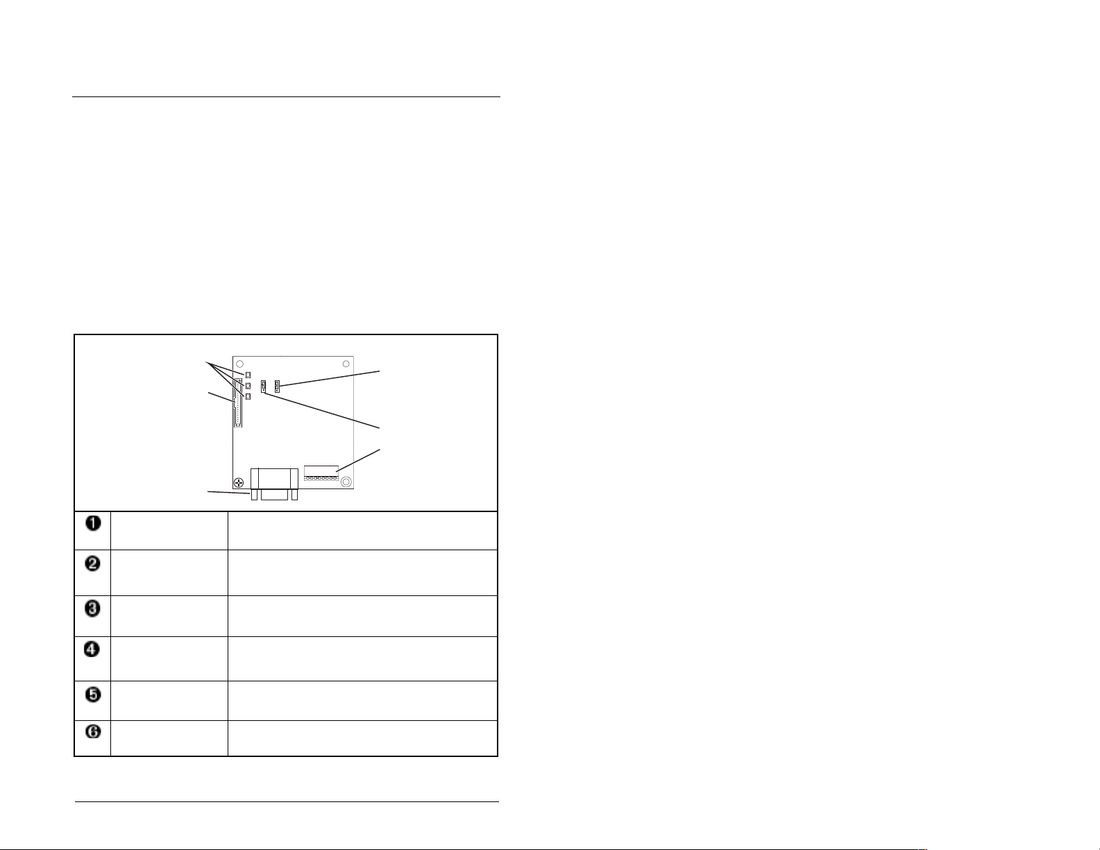
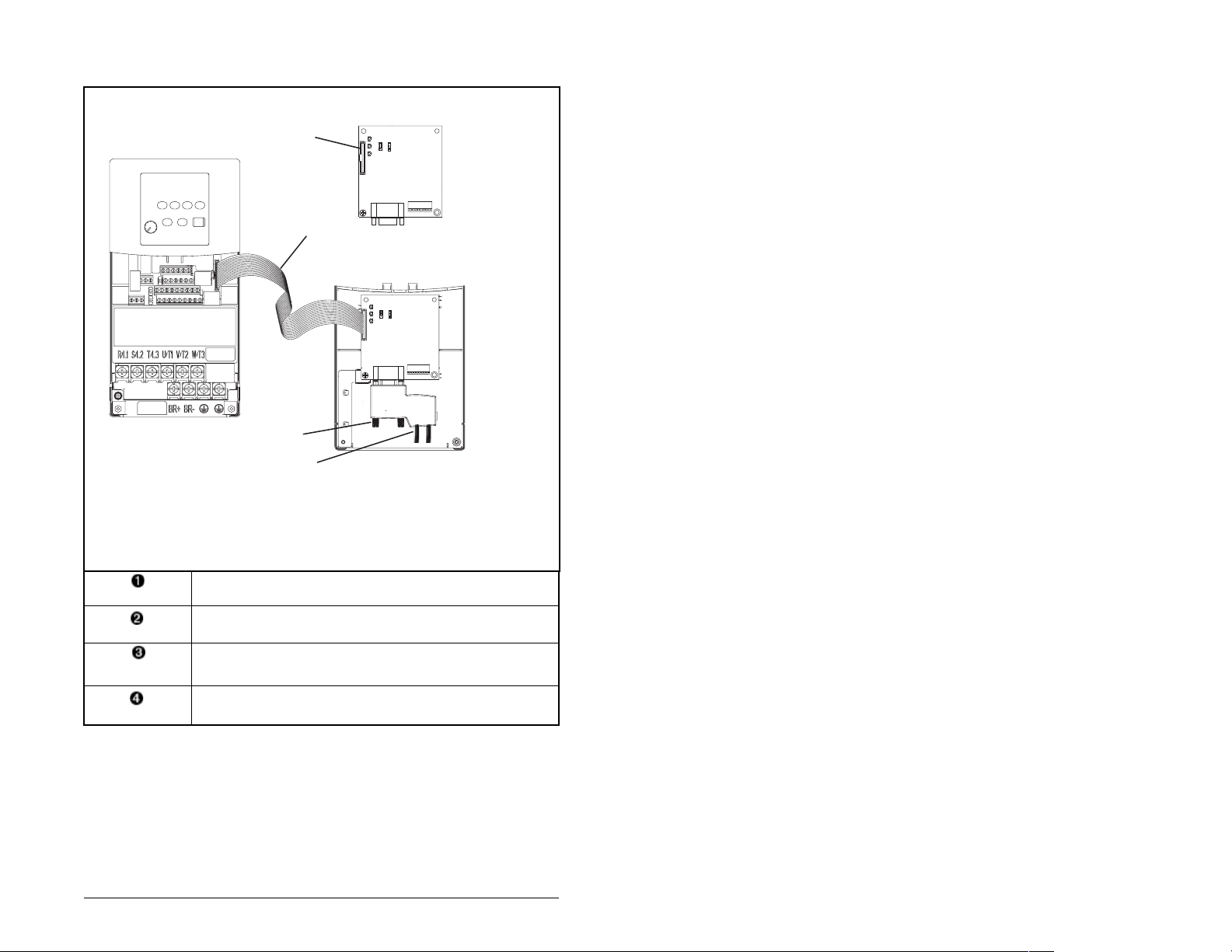
2.1 PROFIBUS Module Components
➊
➋
➌
Status Indicators Three LEDs to indicate the status of the
MDI Connector A 20-pin, single-row shrouded male header. An
PROFIBUS
Connector
Node Address
Switches/ Firmware
Update Switches
Mode Jumper (J2) Selects Single or Multi-Drive mode of
SWAP Jumper (J3) Determines the Intel or Motorola (SWAP) data
connected drive, module, and network.
Internal Interface cable connects to this
connector and a connector on the drive.
A 9-pin, female D-Sub connector.
Switches (SW1-7) for setting the node address
and SW8 for Firmware flash updating.
operation.
format for the corresponding PLC.
➎
❻
➍
Figure 2.1 – Components of the PROFIBUS Module
Getting Started 2-1
Page 12

2.2 Required Equipment
Table 2.1 lists the equipment shipped with the PROFIBUS module.
When you unpack the module, verify that the package includes all of
these items.
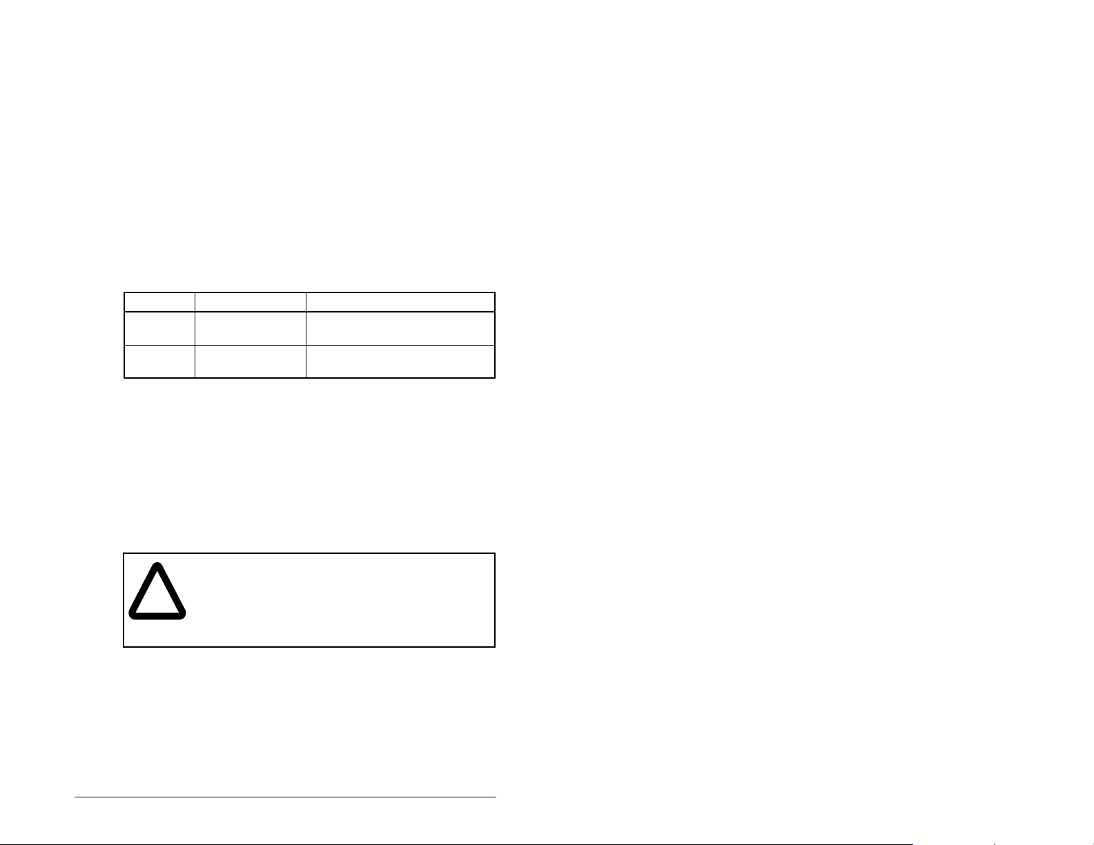
Table 2.1 – Equipment Shipped with the PROFIBUS Module
Item Description
One MDCOMM-PBUS PROFIBUS module
A 2.54 cm (1 in) and a 12.7 cm (5 in) Internal Interface cable (only
one cable is needed to connect the module to the drive)
One grounding wrist strap
One floppy disc with GSD file
PROFIBUS Module User Manual (D2-3530)
Table 2.2 lists user-supplied equipment also required to install and
configure the PROFIBUS mo du l e.
Table 2.2 – Required User-Supplied Equipment
Item Description
Small flathead screwdriver
PROFIBUS cable
One 9-pin, male D-Sub PROFIBUS connector.
Note: PROFIBUS connectors are available from a variety of
sources and in various sizes. As such, there may be mechanical
limitations that prohibit the use of some connectors.
Configuration tool, such as:
• LCD OIM
• VS Utilities
• with MDCOMM-232 Serial Converter
PROFIBUS configuration software
Controller configuration software
2-2 PROFIBUS Communications Module
Page 13

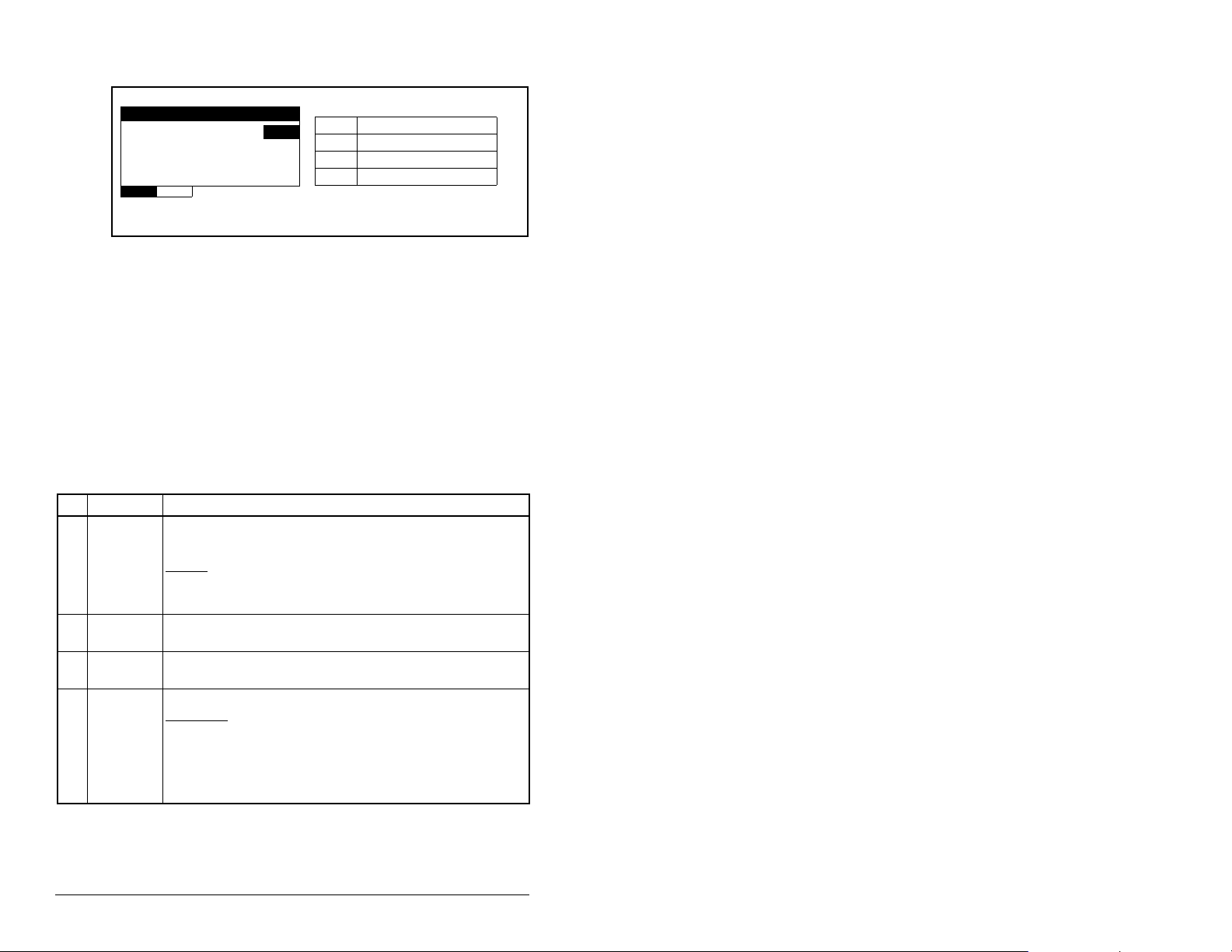
2.3 Installation Checklist
This section is designed to help experienced users start using the
PROFIBUS module. If you are unsure about how to complete a
step, refer to the referenced chapter.
4 Step Action Refer to:
❒
❒
❒
❒
❒
❒
1 Review the safety precautions for the
module.
2 Verify that the MD65 drive is properly
installed.
3 Commission the module.
Set a unique node address using the DIPswitch for Bit 1 to 7 on the module.
4 Install the module.
Verify that the drive and PROFIBUS network
are not powered. Then, connect the module
to the network using a PROFIBUS cable and
to the drive using the Internal Interface cable.
Use the captive screws to secure and ground
the module to the drive.
5 Apply power to the module.
Apply power to the drive and to the network.
The module receives power from the drive.
The status indicators should be green. If they
flash red, there is a problem. Refer to chapter
9, Troubleshooting the PROFIBUS Module
and Network.
6 Set up the drive parameters.
Before starting, configuring and working with
the Profibus module, the following
parameters must be set:
• Start Source (P036) to 5
“RS485(MDI) port” if Start is
controlled from the network.
• Speed Reference (P038) to 5
“RS485(MDI) port” if the Speed
Reference is controlled from the
network.
For Multi-Drive mode, the following drive
parameters must be set: A103, A104, A107.
Throughout
this manual
MD65 AC
Drive User
Manual
(D2-3519)
Chapter 3,
Installing the
PROFIBUS
Module
Chapter 3,
Installing the
PROFIBUS
Module
Chapter 3,
Installing the
PROFIBUS
Module
Chapter 4,
Configuring
the
PROFIBUS
Module
Getting Started 2-3
Page 14

4 Step Action Refer to:
❒
7 Configure the module for your
application.
Set the parameters for the following features
as required by your application:
Chapter 4,
Configuring
the
PROFIBUS
Module
• Node address
• I/O configuration
• Fault actions
❒
❒
8 Apply power to the PROFIBUS master and
other devices on the network.
Verify that the master and network are
installed and functioning in accordance with
PROFIBUS standards, and then apply power
to them.
9 Configure the scanner to communicate
with the module.
Use a network tool for PROFIBUS to
configure the master on the network.
Be sure to:
Chapter 5,
Configuring
the
PROFIBUS
Scanner
• Set up the scan list.
• Map the module data to the scan list.
• Save your PROFIBUS configuration to the
scanner and a file.
10 Create a ladder logic program.
❒
Use a programming tool such as RS Lo g i x to
create a ladder logic program that enables
you to do the following:
• Control the module and connected drive.
• Monitor or configure the drive using Explicit
Messages.
Chapter 6,
Using I/O
Messaging.
Chapter 7,
Using Explicit
Messaging
(Parameter
Protocol)
2.4 Modes of Operation
The PROFIBUS module uses three status indicators to report its
operating status. They can be viewed through the drive cover.
2-4 PROFIBUS Communications Module
Page 15
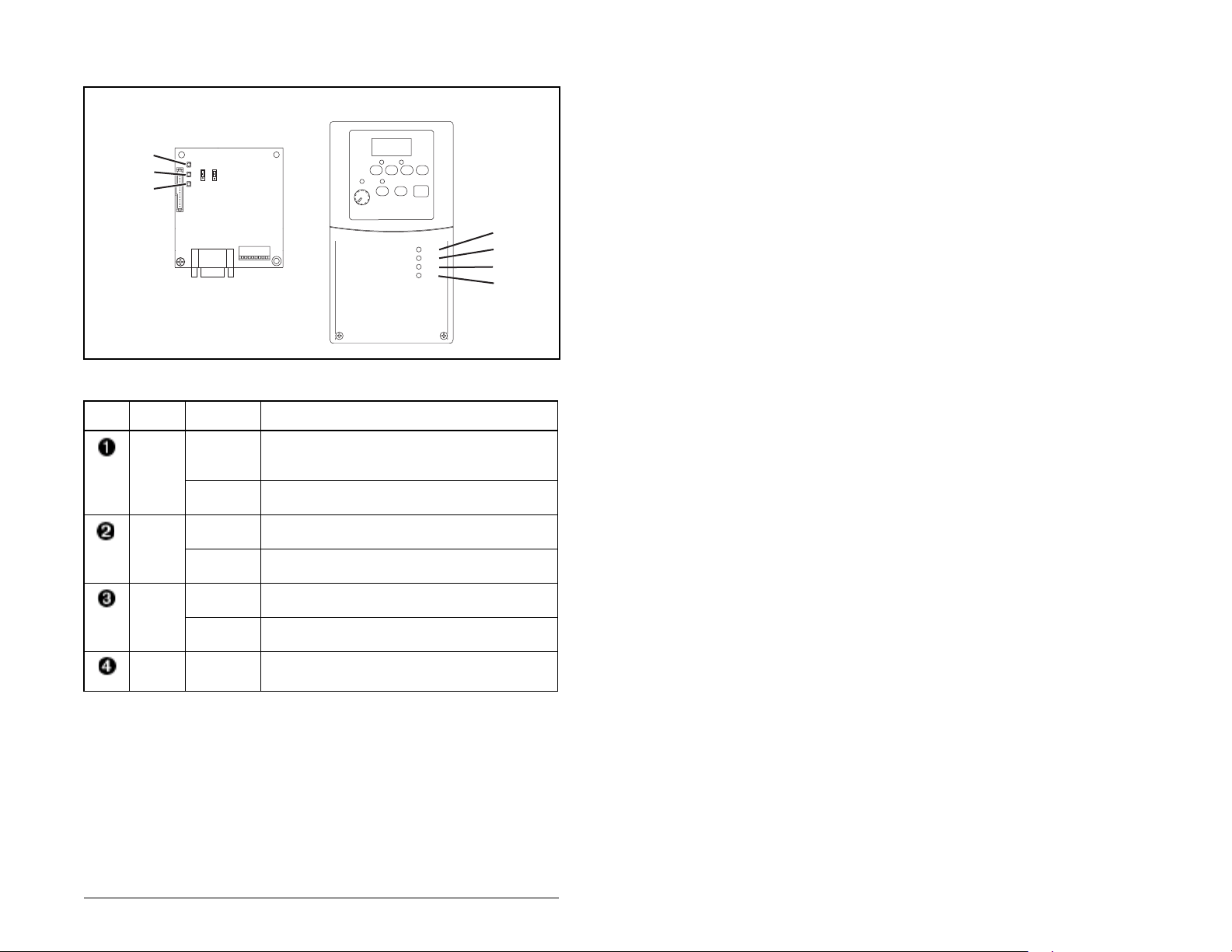
Table 2.3 describes the status indicators shown in figure 2.2.
➊
➋
➌
DRIVE
MS
NET A
NET B
Figure 2.2 – Status Indicators
Table 2.3 – Status Indicator Descriptions
Item Status
Indicator
Status
1
Description
DRIVE Green Normal Operation. The module is properly
connected and is communicating with the
drive.
Flashing
Not used.
Green
MS Green Normal Operation. The module is operational
and is transferring I/O data.
Flashing
Green
Normal Operation. The module is operational
but is not transferring I/O data.
NET A Green Normal Operation. The module is properly
connected and communicating on the network.
Flashing
Not used.
Green
NET B Off Not used for Profibus module.
➊
➋
➌
➍
1. If all status indicators are off, the module is not receiving power. Refer to Chapter 3,
Installing the PROFIBUS Module for installation instructions. For other conditions,
refer to Chapter 9, Troubleshooting the PROFIBUS Module and Network.
Getting Started 2-5
Page 16

2-6 PROFIBUS Communications Module
Page 17

CHAPTER 3
Installing the
PROFIBUS Module
Chapter 3 provides instructions for installing the PROFIBUS module
in a MD65 drive.
3.1 Preparing for an Installation
Before installing the PROFIBUS module, verify that you have all
required equipment. Refer to chapter 2, Getting Started.
3.2 Commissioning the Module
To commission the module, you must set a unique node address
and check the data rate that is used by the network and set in the
GSD-file.
Important: New settings are recognized only when power is
applied to the module. If you change a setting, cycle
power.
ATTENTION: The PROFIBUS module contains
ESD- (Electrostatic Discharge) sensitive parts that
!
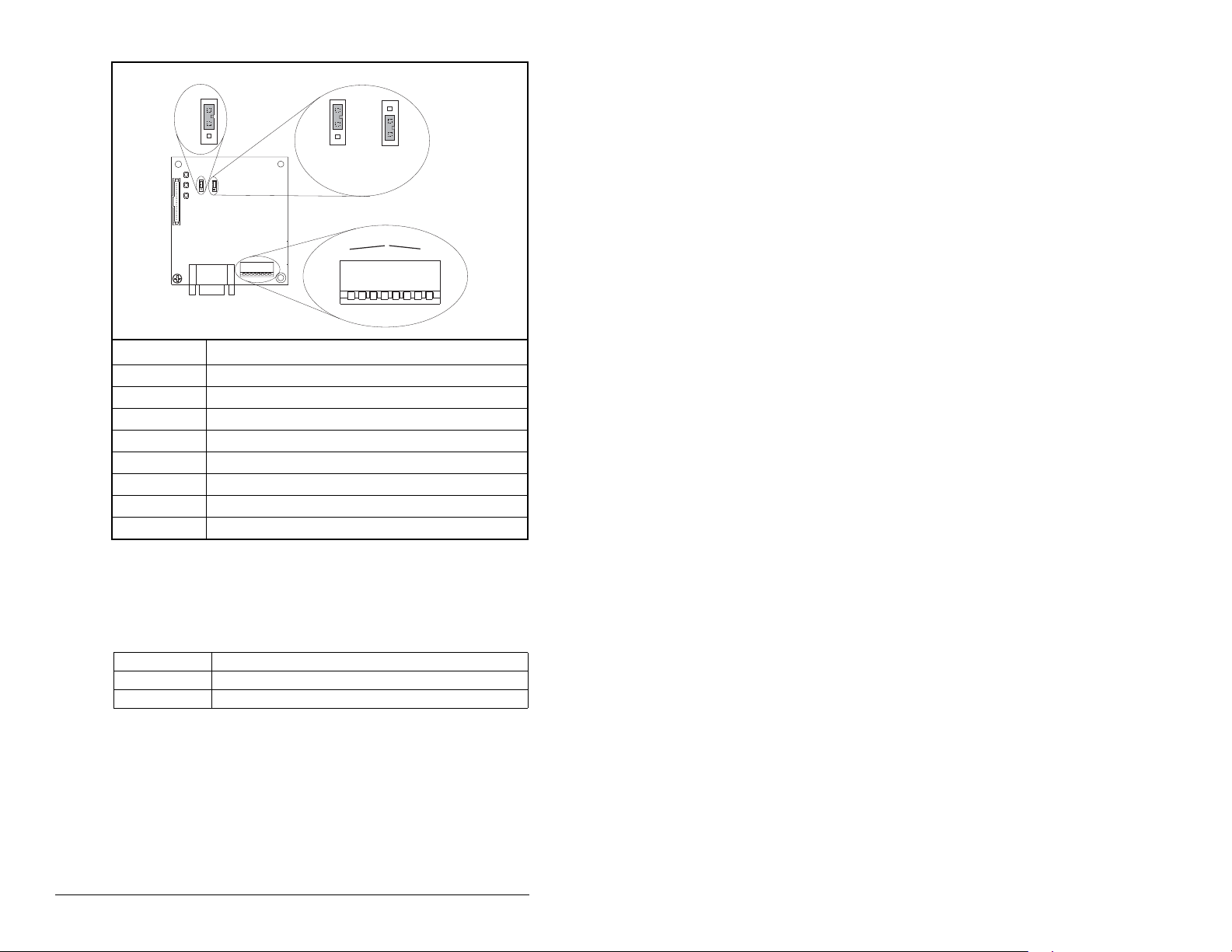
Step 1. Set the node address switches as shown in figure 3.1.
The PROFIBUS Node address/Firmware Update State is set
through the use of an 8-bit DIP switch. The low seven bits let you set
a node address and the valid address allows binary coding 1
through 125. New settings of node address are recognized only
when power is applied to the module, cycle power, or a Reset
Module Command. The MSB bit provides write access for the
module flash firmware update. In normal operating state, SW8
should be set to 1.
Installing the PROFIBUS Module 3-1
can be damaged if you do not follow ESD control
procedures. Static control precautions are required
when handling the module. Failure to observe these
precautions could result in damage to equipment.
Page 18
J3
SWAP
J2
Single Drive
Operation
J2
Multi-Drive
Operation
NODE
ADDRESS SWITCHES
2
1
3
4
2
1
3
4
UP = OPEN = 1
Description
5
7
6
8
5
7
6
8
Switches
J4
J1
1
SW1 Least Significant Bit (LSB) of Node Address
SW 2 Bit 1 of Node Address
SW 3 Bit 2 of Node Address
SW 4 Bit 3 of Node Address
SW 5 Bit 4 of Node Address
SW 6 Bit 5 of Node Address
SW 7 Most Significant Bit (MSB) of Node Address
SW 8 SW8 Firmware Update
Figure 3.1 – Setting the Node Address
1. The factory default states of all switches are UP, and have the default
address of 3.
Table 3.1 – SW8 Setting
SW 8 Setting Description
0 Write Access Firmware Update
1 Normal Operating State
3-2 PROFIBUS Communications Module
Page 19

Table 3.2 – Node Address Switch Settings (UP = OPEN = 1)
Switch Setting Node
SW 1 SW 2 SW 3 SW 4 SW 5 SW 6 SW 7 Addr
00000000
10000001
01000002
11000003
00100004
10100005
01100006
11100007
00010008
10010009
010100010
110100011
001100012
101100013
011100014
111100015
000010016
100010017
010010018
110010019
001010020
101010021
011010022
111010023
000110024
100110025
-0000111112
1000111113
0100111114
1100111115
0010111116
1010111117
0110111118
1110111119
0001111120
1001111121
0101111122
1101111123
1101111124
1011111125
Installing the PROFIBUS Module 3-3
Page 20
Step 2. Verify the Network Baud rate, which is set by the network
master and depends on cable length.
The MDCOMM-PBUS module uses the Auto-Baud and
supports the following different data rates: 9.6 kpbs, 19.2
kpbs, 45.45 kpbs, 93.75 kpbs, 187.5kpbs, 500 kpbs, 1.5
Mpbs, 3 Mpbs, 6 Mpbs, and 12 Mpbs.
The Auto-Baud function allows the module to recognize
the current baud rate and sets itself to the transmission
rate by the master automatically. After detecting the
correct baud rate, the baud rate that was found is
monitored continuously. Auto-Baud is always active.
Step 3. Set the Byte Swap jumper J3, which determines the Intel
or Motorola (position SWAP) data format depending on
the corresponding PLC. See Figure 3.1.
Step 4. Verify that the jumper J2 is in position “1X” for Single
Jumper Setting Description
Right position or
jumper missing
Left position Sets the module for Multi-Drive operation mode
Drive operation, or set J2 in “5X” for Multi Drive operation.
Table 3.3 – Jumper Settings
Sets the module for Single drive mode (default
setting) using a single drive connection.
Important:In this mode, connections to multiple
drives must be removed since all
powered and connected hosts will
respond to any message sent by the
module.
using up to 5 different drives. MDI peripherals do
not operate with the modul e in th i s mod e.
3.3 Connecting the Module to the
Network
ATTENTION: The drive may contain high voltages
that can cause injury of death. Remove all power
!
Step 1. Remove power from the drive.
Step 2. Use static control precautions.
Step 3. Remove the drive cover.
3-4 PROFIBUS Communications Module
from the drive, and then verify power has been
removed before installing or removing a PR OFIBUS
module. F ailure to observe th ese precautions co uld
result in severe bodily injury or loss of life.
Page 21
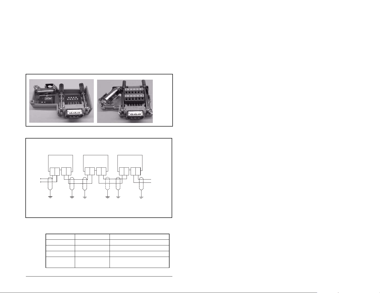
Step 4. Connect a PROFIBUS connector to the cable. Only use
cable that conforms to Profibus cable standards. Belden
#3079A Profibus cable or equivalent is recommended.
Note: PROFIBUS connectors are available from a v ariety
of sources and in various sizes. As such, there may be
mechanical limitations that prohibit the use of some
connectors. Phoenix Subcon Plus M1 (Part # 2761826) or
ERNI PROFIBUS vertical (Node Part # 103658 and
Termination Part # 103659 connectors) are
recommended for use with MD65 and other Reliance
Electric MDI-based drives.
Figure 3.2 – ERNI and Phoenix Subcon Connectors
A
B
B
A
B
A
A
B
AB
A
B
Figure 3.3 – Network Wiring Diagram
Table 3.4 – MDCOMM-PBUS DB-9 Pin Layout
Terminal Signal Function
Housing Shield
1 Not connected
2 Not connected
3 B-LINE Positive RxD/TxD, according
to RS485 specification
Installing the PROFIBUS Module 3-5
Page 22
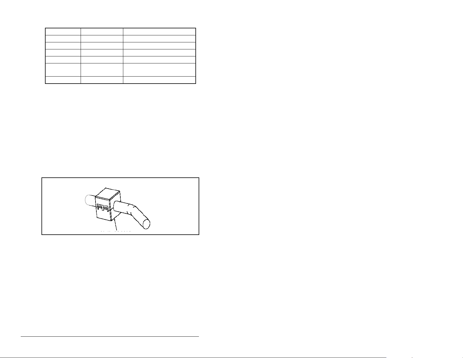
Table 3.4 – MDCOMM-PBUS DB-9 Pin Layout (Continued)
Terminal Signal Function
4RTS
5 GND BUS Isolated GND from bus
6 +5V BUS Isolated +5V from bus
7 Not connected
8 A-LINE Negative RxD/TxD according
to RS485 specification
9 Not connected
Step 5. Connect the PROFIBUS cab le to the module, secure it
with the two screws on the connector, and route it through
the bottom of the MD65 drive. See figure 3.3.
Note: The screws on some connectors tie the PROFIBUS
cable ground/shield to the metal of the socket. In some
cases, PROFIBUS will not operate correctly without this
connector.
Keep communication wiring away from high noise
sources such as motor cables.
Step 6. Depending on the switching frequency of the MD65, it is
optional to use the ferrite cable clamp around the
communication cables next to the D-Sub connector, to
reduce high frequency emission. See figure 3.4.
Figure 3.4 – Optional Clamp-On Ferrite Cable Clamp
3-6 PROFIBUS Communications Module
Page 23
To meet the requirements of EN55011 Class A or B, the conditions
listed below must be satisfied.
Switching
Frequency of MD65
EN55011
Class A EN55011 Class B
4 kHz Use one ferrite Ferrishield (part No.
HI28B2039) or Fair-Rite (part No.
0443164151)
6 kHz No ferrite
required
8 kHz
16 kHz Use three clip ferrites TDK, type
ZCAT 3035-1330
Note: For the conditions to satisfy the essential
requirements for CE compliance on MD65 drives. please
refer to the MD65 manual, D2-3519.
In applications where first environment, unrestricted
distribution is requested (EN55011 group 1, class B), the
installation requires a shielded enclosure.
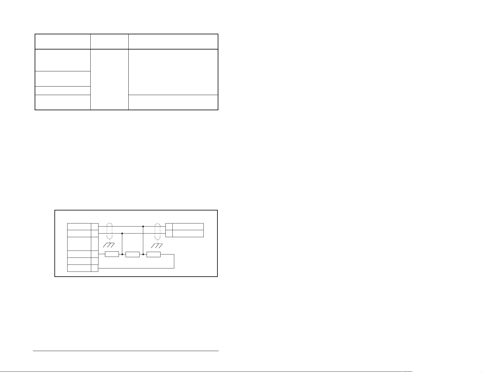
3.4 Terminating the Network
The first and last node on the PROFIBUS network needs to be
terminated by using a PROFIBUS connector with terminating
resistors. See figure 3.5.
R x D / T x D - N 8
R x D / T x D - P 3
V c c 6
3 9 0 2 2 0 3 9 0 O h m
G N D 5
Figure 3.5 – Connection for Terminating Resistors
A
B
8 R x D / T x D - N
3 R x D / T x D - P
Some connector manufacturers offer standard terminating
connectors, such as the yellow ERNI PROFIBUS termination
vertical connector (Part # 103659). Standard PROFIBUS node
connectors, such as the Phoenix Subcon Plus M1 (Part #2761826),
can be configured as a terminating connector by adding resistors.
Installing the PROFIBUS Module 3-7
Page 24

3.5 Connecting the Module to the Drive
Step 1. Remove power from the drive.
Step 2. Use static control precautions.
Step 3. Mount the module on the required special dr ive cover
(ordered separately).
• C Frame: Use the module screw to secure the module to
the cover.
• B F rame: Disregard the screw and snap the module in
place.
Important:For C Frame drives , tighten the module’s low er left screw
Step 4. Connect the Internal Interface cable to the MDI port on
to ground the module. For B Frame drives, install the
special drive cover onto the drive using both cover
fasteners to ground the module.
the drive and then to the MDI connector on the module.
3-8 PROFIBUS Communications Module
Page 25
Profibus Module
➊
➋
MD65 Drive
B and C Frames
(cover removed)
➍
➌
Back of Cover
Back of Required Special Drive Cover
(ordered separately):
Part Number 6MD-COMMCVRB for B Frame
Part Number 6MD-COMMCVRC for C Frame
MDI Connector
15.24 cm (6 in) Internal Interface cable
PROFIBUS cable
Retaining screws
Figure 3.6 – MDI Ports and Internal Interface Cables
Installing the PROFIBUS Module 3-9
Page 26
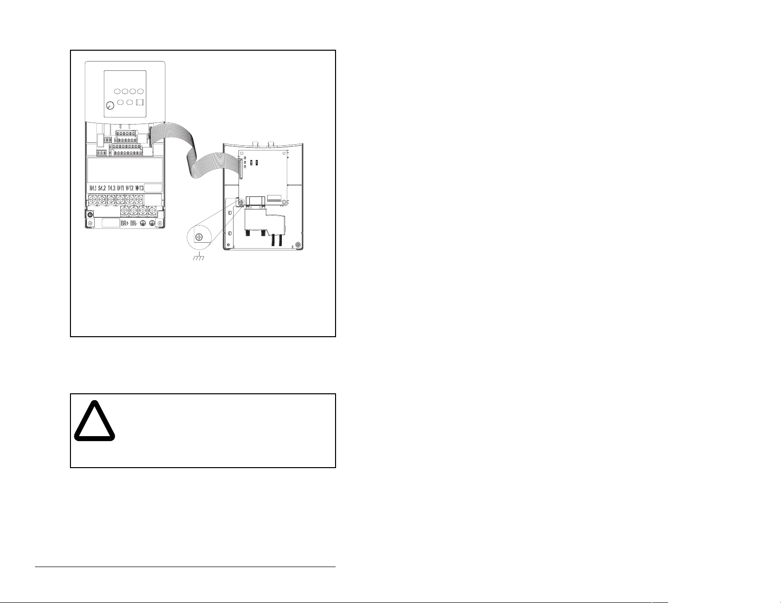
MD65 Drive
B and C Frames
(cover removed)
Ground for C Frame Drives
For B Frame drives, the lower left module
screw does not ground the module. To
ground the module, install the special drive
cover onto the drive using both cover fasteners.
Figure 3.7 – Mounting the Adapter
3.6 Applying Power
ATTENTION: Unpredictable operation may occur if
parameter settings and switch settings are not
!
compatible with your application. V erify that settings
are compatible with your application before applying
power to the drive. Failure to observe these
precautions could result in severe bodily injury or
loss of life.
Module Mounted
on Back of Cover
Step 1. Install the required special cover on the drive. The status
indicators can be viewed on the front of the drive after
power has been applied.
Step 2. Ensure that the module will have a unique address on the
network. If a new address is needed, reset its switches.
See section 3.2, Commissioning the Module.
3-10 PROFIBUS Communications Module
Page 27

Step 3. Apply power to the drive. The module receives its power
from the connected drive and the network. When you
apply power to the product and network for the first time,
the status indicators should be green after an
initialization. If the status indicators are red, there is a
problem. Refer to chapter 8, Troubleshooting the
PROFIBUS Module and Network.
Step 4. Apply power to the master device and other devices on
the network.
Installing the PROFIBUS Module 3-11
Page 28

Installing the PROFIBUS Module 3-12
Page 29

CHAPTER 4
Configuring the
PROFIBUS Module
Chapter 4 provides instructions and information for setting the
parameters in the module.
For a complete list of parameters, refer to Appendix B, PROFIBUS
Module Parameters. For definitions of terms in this chapter, refer to
the Glossary.
4.1 Configuration Tools
The PROFIBUS module stores parameters and other information in
its own non-volatile memory. Therefore, you must access the
module to view and edit its parameters. Table 4.1 lists the tools that
can be used to access the module parameters.
Table 4.1 – Configuration Tools
Tool Refer to:
VS Utilities Software VS Utilities online help
LCD OIM Section 4.2
Configuring the PROFIBUS Module 4-1
Page 30
4.2 Using the LCD OIM to Configure the
Module
Use the procedure in figure 4.1 to access the parameters on the
PROFIBUS module using the LCD OIM. If you are unfamiliar with
the operation of the LCD OIM, refer to the MD65 AC Drive User
Manual (D2-3519) for more information.
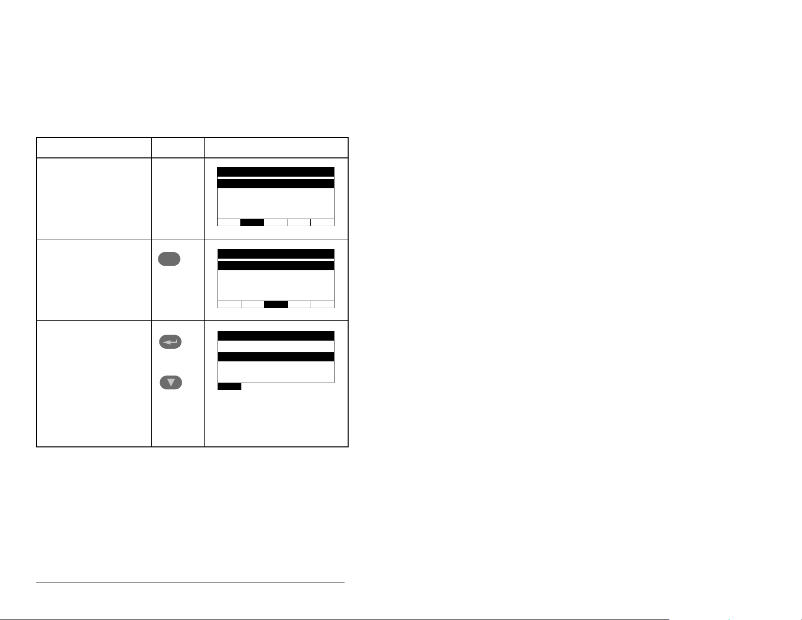
Table 4.2 – Using the LCD OIM or CopyCat Keypad
Step Key(s) Example Screens
1. Po wer up the drive.
Plug the OIM or
CopyCat Keypad into
the drive. The
Parameters menu for
the drive will be
displayed.
2. Press Sel key once to
display the Device
Select menu.
3. Press Enter to display
the MDI Devices
menu. Press Down
Arrow to scroll to
MDCOMM-PBUS.
Sel
and
Parameters
Groups
Linear List
Changed Params
DIAG PA R AM DSEL MEM SEL X
Device Selected
MDI Devices
DIAG PARAM DSEL MEM SEL X
MDI Devices
MD65
MDCOMM-PBUS
4-2 PROFIBUS Communications Module
Page 31

Table 4.2 – Using the LCD OIM or CopyCat Keypad
Step Key(s) Example Screens
4. Press Enter to select
the Profibus module.
The Parameters menu
for the module will be
Parameters
Linear List
Changed Params
displayed.
DIAG PA R AM DSEL MEM SEL X
5. Press Enter to access
the parameters. Edit
the module parameters
using the same
techniques that you
use to edit parameters.
Mode RO
Parameter: #
Single Drive 0
VAL UE LIMITS SEL X
001
4.3 Using V*S Utilities via MDCOMM-232
V*S Utilities can be used to access parameters in the module. Use
V*S Utilities (version 4.0) and the MDCOMM-232 (version 2.001 or
higher). For more information on V*S Utilities, see instruction
manual D2-3488.
Step 1. Connect the MDCOMM-232 to the MD65 and to a PC
Step 2. Open V*S Utilities and press the “Connect Serial” button
serial COM port, then apply power to the MD65 drive.
in the toolbar. In the left window under “Devices,” “Node 1:
MD65” appears. There are three configurable devices: the
MD65, the Profibus module and the serial module
MDCOMM-232.
Figure 4.1 – Using V*S Utilities
Configuring the PROFIBUS Module 4-3
Page 32

4.4 Setting the Node Address
The PROFIBUS Node address/Firmware Update State is set
through the use of an 8-bit DIP switch. The low seven bits let you set
a node address and the valid address allows binary coding 1
through 125. New settings of node address are recognized only
when power is applied to the module, cycle power, or a Reset
Module Command. The MSB bit provides write access for the
module flash firmware update. In normal operating state, SW8
should be set to 1.
J3
SWAP
J2
Single Drive
Operation
J2
Multi-Drive
Operation
J4
Switches
J1
1
NODE
ADDRESS SWITCHES
2
1
3
4
2
1
3
4
UP = OPEN = 1
Description
5
7
6
8
5
7
6
8
SW1 Least Significant Bit (LSB) of Node Address
SW 2 Bit 1 of Node Address
SW 3 Bit 2 of Node Address
SW 4 Bit 3 of Node Address
SW 5 Bit 4 of Node Address
SW 6 Bit 5 of Node Address
SW 7 Most Significant Bit (MSB) of Node Address
SW 8 SW8 Firmware Update
Figure 4.2 – Setting the Node Address
1. The factory default states of all stitches are UP. The fault address is 3.
SW 8 Setting Description
0 Write Access Firmware Update
1 Normal Operating State
Refer to section 3.2, Commissioning the Module, for more
information.
4-4 PROFIBUS Communications Module
Page 33

4.5 Setting the I/O Configuration
The I/O configuration determines the number of drives that will be
represented on the network as one node by the module. If the Mode
Jumper is set to the Single mode position, only one drive is
represented by the module and MDI I/O Cfg (parameter 11) has no
effect. If the Mode Jumper J2 is set to the Multi-Drive position, up to
five drives can be represented as one node by the module.
Step 1. Set the value in MDI I/O Cfg (parameter 11):
MDI I/O Cfg
Para meter : #
Drive 0 0
VAL UE LIMITS SEL X
Drive 0 is the MD65 with the MDCOMM-PBUS module installed.
Drives 0-1 through 0-4 are MD65 and/or MD60 drives that multidrop to the RJ45 (RS-485) port on Drive 0. Refer to Chapter 8,
Using Multi-Drive Mode, for more information.
Step 2. If a drive is enabled, configure the parameters in the drive
to accept the Logic Command and Reference from the
module. For example, set Start Source (parameter 36)
and Speed Reference (parameter 38) in a MD65 drive to
“MDI Port 5.”
Step 3. Reset the module. Refer to section 4.6.2, Resetting the
Module.
Value Description
011
0 Drive 0 (Default) ✓✓
1Drives 0-1 ✓
2Drives 0-2 ✓
3Drives 0-3 ✓
4Drives 0-4 ✓
Mode Jumper Position
Single Multi-Drive
The module is ready to receive I/O from the master (i.e., scanner).
You must now configure the scanner to recognize and transmit I/O
to the module. Refer to chapter 5, Configuring the PROFIBUS
Scanner, for more information.
Configuring the PROFIBUS Module 4-5
Page 34

4.6 Setting a Fault Action
ATTENTION: Comm Flt Action (parameter 9) and
Idle Flt Action (parameter 10) let you determine the
!
By default, when communications are disrupted (for example, a
cable is disconnected) or the master is idle, the drive responds by
faulting if it is using I/O from the network. You can configure a
different response to communication disruptions using Comm Flt
Action (parameter 9) and a different response to an idle scanner
using Idle Flt Action (parameter 10).
4.6.1 Changing the Fault Action
Set the values of Comm Flt Action (parameter 9) and Idle Flt Action
(parameter 10) to the desired responses as shown in table 4.3.
Table 4.3 – Selections for Drive Response to Communication Fault
Value Action Description
0 Fault (default) The drive is faulted and stopped (Default).
1 Stop The drive is stopped, but not faulted.
2 Zero Data The drive is sent 0 for output data after a
3 Hold Last The drive continues in its present state after a
4 Send Flt Cfg The drive is sent the data that you set in the
action of the module and connected drive if
communications are disrupted or the scanner is idle.
By default, these parameters fault the drive. You can
set these parameters so that the drive continues to
run. Precautions should be taken to ensure that the
settings of these parameters do not create a risk of
injury or equipment damage.
communications disruption. This does not
command a stop.
communications disruption.
fault configuration parameters 13 and 14 (Flt
Cfg Logic and Flt Cfg Ref).
Comm Flt Action
Para meter : #
Faul t 0
VAL UE LIMITS SEL X
Figure 4.3 – Fault Action Screens on an LCD OIM
009
Idle Flt Action
Para meter : #
Fault 0
VALU E LIMITS SEL X
010
4-6 PROFIBUS Communications Module
Page 35
Changes to these parameters take effect immediately. A reset is not
required.
If Multi-Drive mode is used, the same fault action is used by the
module for all of the drives it controls (Drive 0, Drives 0-1 to Drives
0-4).
4.6.2 Setting the Fault Configuration Parameters
If you set module Comm Flt Action (parameter 9) or module Idle Flt
Action (parameter 10) to “Send Flt Cfg,” the values in the
parameters shown in table 4.4 are sent to the drive after a
communications fault and/or idle fault occurs. You must set these
parameters to values required by your application.
Table 4.4 – Fault Configuration Parameters
Number Name Description
13 Flt Cfg Logic A 16-bit value sent to the drive
for Logic Command
14 Flt Cfg Ref A 16-b it value sent to the dr ive
as a Reference
Changes to these parameters take effect immediately. A reset is not
required.
4.6.3 Resetting the Module
Changes to switch settings or some module parameters require that
you reset the module before the new settings take effect. You can
reset the module by cycling po wer to the drive or by using Rese t
Module (parameter 8).
ATTENTION: If the module is transmitting control
I/O to the drive, the drive may fault when you reset
!
Configuring the PROFIBUS Module 4-7
the module. Determine how your drive will respond
before resetting a connected module. Failure to
observe this precaution could result in bodily injury
or damage to equipment.
Page 36
Set parameter 8 (Reset Module) to “Reset Module.” See figure 4.4.
Reset Module
Param ete r: #
Ready 0
VAL UE LIMITS SEL X
Figure 4.4 – Reset Screen on an LCD OIM
Value Description
008
0 Ready (Default)
1 Reset Module
2 Set Defaults
When you enter 1 (“Reset Module”), the module will be
immediately reset. When you enter 2 (“Set Defaults”), the module
will set all module parameters to their factory-default settings. The
value of this parameter will be restored to 0 (“Ready”) after the
module is reset.
4.7 Viewing the Module Configuration
The parameters in table 4.5 provide information about how the
module is configured. You can view these parameters at any time.
Table 4.5 – Module Configuration Status Parameters
No. Name Description
01 Mode Displays the Single or Multi-Drive operating mode selected
with the jumper J2 on the module.
Values
0 = Single drive operation
1 = Multi-Drive operation
04 P-DP Addr
Actual
05 P-DP Rate
Actual
12 MDI I/O
Actual
PROFIBUS Node Address actually used by the module.
PROFIBUS actual operating data rate.
Displays the Drives that are active in the Multi-Drive mode:
Bit Values
0 = Drive 0 Active
1 = Drives 0-1 Active
2 = Drives 0-2 Active
3 = Drives 0-3 Active
4 = Drives 0-4 Active
4-8 PROFIBUS Communications Module
Page 37

CHAPTER 5
Configuring the
PROFIBUS Scanner
PROFIBUS scanners are available from several manufacturers,
including SST. SST PROFIBUS scanners come with a software tool
for configuring the scanner (see figure 5.2).
Chapter 5 provides instructions on how to utilize the SST
PROFIBUS configuration software tool to:
• Install the MDCOMM-PBUS GSD file in the software tool library.
• Configure the SST-PFB-SLC PROFIBUS scanner.
Important:The configuration of other manufacturer’s scanners may
differ significantly from this example. Please ref er to y our
scanner manufacturer’s documentation.
5.1 Configuring a Simple Network: An
Example
In this example, we will be configuring two MD65 drives to be
Station 1 and Station 2 on a PROFIBUS network. This will be the
configuration used throughout the manual, including the ladder
examples. Apart from the node address and scanner mapping, they
will have identical configurations. This chapter describes the steps
to configure a simple network like the network in figure 5.1.
Configuring the PROFIBUS Scanner 5-1
Page 38
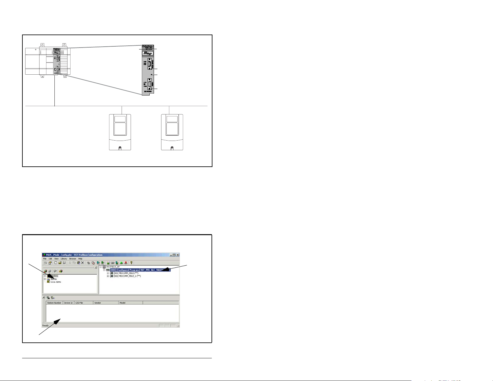
Station 0
n
COMM
LED
SYS LED
Config Port
Front Label
PROFIBUS Port
MD65
Station 1
Figure 5.1 – Example PROFIBUS Network
MD65
Station 2
5.2 SST Profibus Configuration Software
Tool
SST Profibus Scanners come with a software tool for configuring
the scanner. See figure 5.2.
Device
Library
window
Online
Browse
window
Network
Configuratio
window
Figure 5.2 – SST PROFIBUS Configuration Software Tool
5-2 PROFIBUS Communications Module
Page 39

5.3 Installing the MDCOMM-PBUS GSD
File in the Software Tool Library
GSD files are used by software tools to configure the network, in
other words, to map and define the I/O in a PROFIBUS scanner. A
GSD file is required for each type of module on the network.
For example: The MDCOMM-PBUS GSD file is “R_E_07FF.gsd”
and a copy of the file is provided on a floppy disk with each
MDCOMM-PBUS PROFIBUS module. The file can also be
downloaded from the Internet by going to: www.reliance.com.
Follow the steps outlined below only when a new GSD file needs to
be added to the SST PROFIBUS Configuration Software Tool.
Typically, this is only done once, after the software tool is initially
installed or if configuring a MDCOMM-PBUS on the network for the
very first time with this software tool.
The software tool comes with standard data files as shown in figure
5.3. Additional data files, such as the MDCOMM-PBUS GSD file,
will need to be added to configure the MDCOMM-PBUS in the
scanner.
Figure 5.3 – Standard Data Files
Step 1. Click on the “New Device” icon to add GSD files to
the software library tool.
Step 2. An “Add PROFIBUS devices” applet window will appear
Configuring the PROFIBUS Scanner 5-3
(see figure 5.4). Prompts for the location of the
PROFIBUS data files to be added to the library will follow.
Page 40
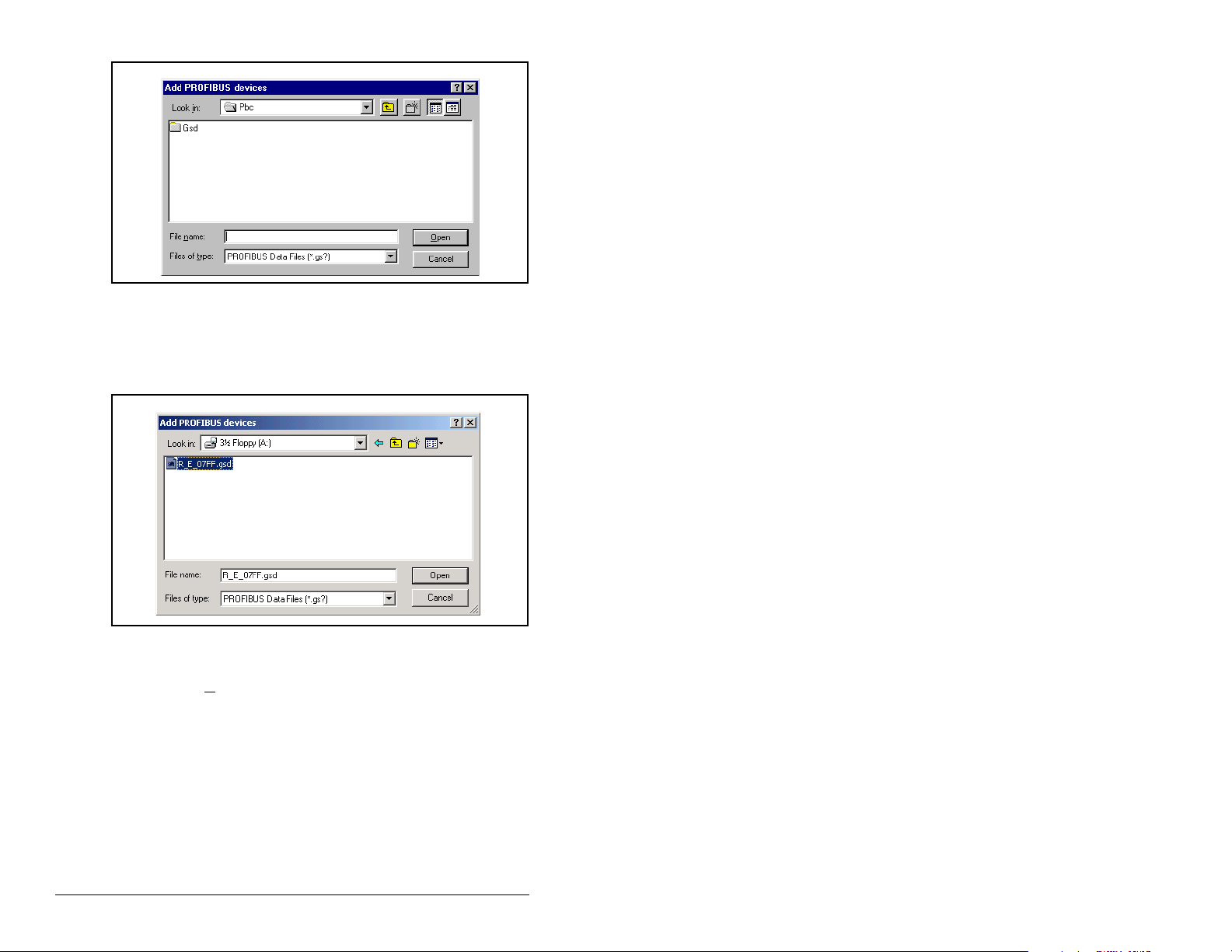
Figure 5.4 – Add PROFIBUS Devices Applet Window
Step 3. Find the directory location of the data file(s) you wish to
add (typically, the source location is a floppy disk in drive
A:). “R_E_07FF.gsd” is the GSD file for the
MDCOMM-PBUS as shown in figure 5.5.
Figure 5.5 – Adding the GSD File for the RECOMM-PBUS
Step 4. Select “R_E_077FF.gsd” for the MDCOMM-PBUS and
click O
pen.
5-4 PROFIBUS Communications Module
Page 41

Step 5. Click on the (+) sign of the Slaves folder as shown in
The software tool will automatically create a Reliance Electric
sub-folder (in the Slaves folder) if it does not already exist. The
MDCOMM-PBUS is now shown in the library and the software tool
is now ready to configure a MDCOMM-PBUS on a PROFIBUS
network.
figure 5.6.
Figure 5.6 – Masters/Slaves Library Window
5.4 Configuring the SST-PFB-SLC
PROFIBUS Scanner
The following steps are performed to configure the SST-PFB-SLC
scanner using the SST PROFIBUS Configuration Software Tool. In
our example, the PROFIBUS network will consist of a SLC master
and two MD65 drives working in Single drive mode. The
configuration example is as follows:
• Drive 0: Ctrl/Stat & Ref/Fdbk enabled - Parameter Access
enabled
• Drive 1: Ctrl/Stat & Ref/Fdbk enabled - Parameter Access
enabled
The SLC processor must be in Program mode to configure the
scanner.
Step 1. Click on the (+) sign of the Masters folder in the Library
Configuring the PROFIBUS Scanner 5-5
window to open the SST sub-folder. A v ailable Profib us DP
masters are displayed in this sub-fold er.
Page 42
Step 2. Click on the (+) sign of the Slaves folder in the Library
window and the Reliance Electric sub-folder to display
the available Profibus DP slaves or the RECOMM-PBUS
slave. Refer to figure 5.6.
Step 3. Double-click the SST-PFB-SLC MASTER in the Masters
folder in the Library window to add the scanner to the
network.
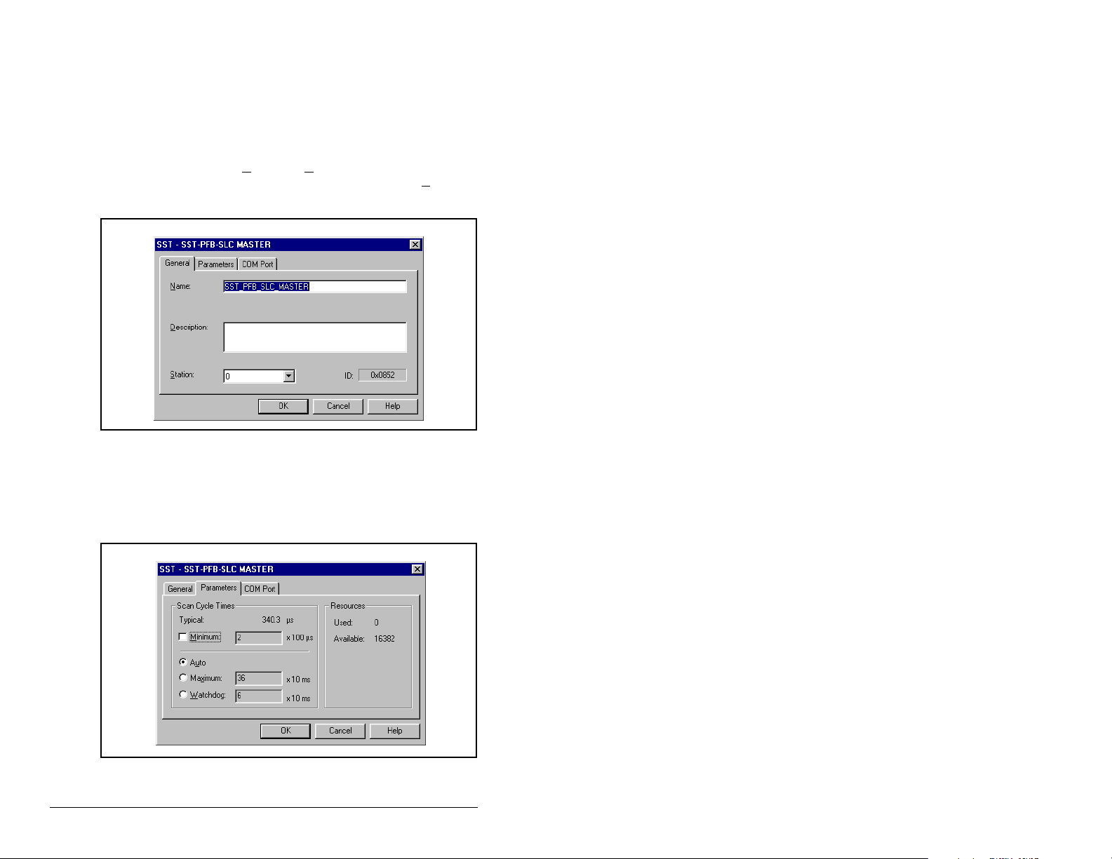
Step 4. A user-defined N
the scanner. In our example, the scanner will be S
ame and Description can be given to
tation 0
on the network, as shown in figure 5.7.
Figure 5.7 – SST-SST-PFB-SLC Master (General) Dialog Box
Step 5. Click on the Parameters tab to view the Scan Cycle
Times.
In our example, use the default settings as shown in
figure 5.8.
Figure 5.8 – Scan Cycle Times Dialog Box
5-6 PROFIBUS Communications Module
Page 43

Connection and Baud Rate settings configure how the software tool
will communicate with the CONFIG RS232 port on the scanne r.
Step 6. Click on the COM Port tab.
Step 7. Accept the settings in our example (COM1 on the PC at
115200 bps baud rate), as shown in figure 5.9.
Figure 5.9 – COM Port Default Settings
Step 8. The scanner will appear in the network window as shown
in figure 5.10. Double-click on the scanner in the network
window.
Figure 5.10 – Scanner Network Window
Step 9. Double-click on the MDCOMM-PBUS listed in the
Reliance Electric library folder. A user-defined N
D
escription can be given to this MDCOMM-PBUS.
Reliance Electric RECOMM-PBUS
In our example, this device will be S
tation 1 on the network. Other
ame and
stations may be chosen by using the arrow to display a drop-down
list in the S
Configuring the PROFIBUS Scanner 5-7
tation window.
Page 44

Figure 5.11 – Reliance Electric Library Dialog Window
Logic Command / Status, Reference / Feedback, Datalinks and
Parameter Access (explicit messaging) modules are added using
the Modules tab.
Step 10. Click on the Modules tab. Click A
dd to view the choice of
modules.
Figure 5.12 – Available Modules: Ctrl/Stat & Ref/Fdbk (2x2Bytes) Window
5-8 PROFIBUS Communications Module
Page 45
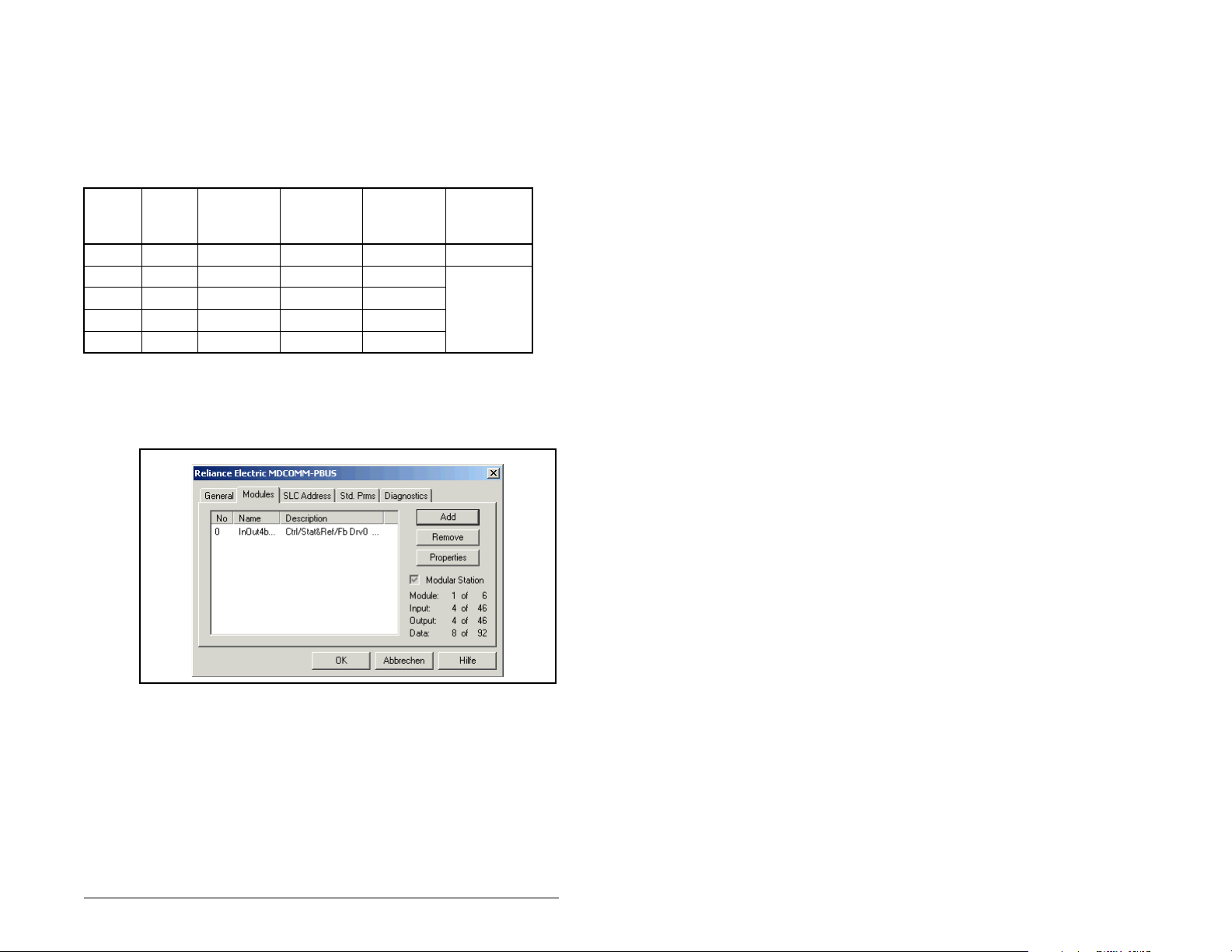
In our example, Station 1 will be controlled using Logic Command /
Status and Reference / Feedback. The Parameter Access will also
be used. Because the Mode Jumper J2 on the module is set to “1X”
for Single Drive (default) and MDI I/O Cfg (parameter 11) is set to
Drive 0. Logic Command/Reference uses 4 bytes and Logic
Status/Feedback uses 4 bytes.
Table 5.1 – Input/Output Size Configurations
Logic
Input
Size
Output
Size
44
88
12 12
16 16
20 20
Command/
Feedback
✔✔Drive 0 Single
✔✔Drives 0-1 Multi-Drive
✔✔Drives 0-2
✔✔Drives 0-3
✔✔Drives 0-4
Reference/
Feedback
MDI I/O
Cfg (11) Mode (1)
Step 11. Select “Ctrl/Stat & Ref/Fdbk (2+2bytes)” from the
“Availab le Modules” list as shown in figure 5.13. Click OK.
The “Ctrl/Stat & Ref/Fdbk” (2+2 bytes) module has now
been added as shown in figure 5.13.
Figure 5.13 – Modules: Ctrl/Stat & Ref/Fdbk Viewing Window
Configuring the PROFIBUS Scanner 5-9
Page 46
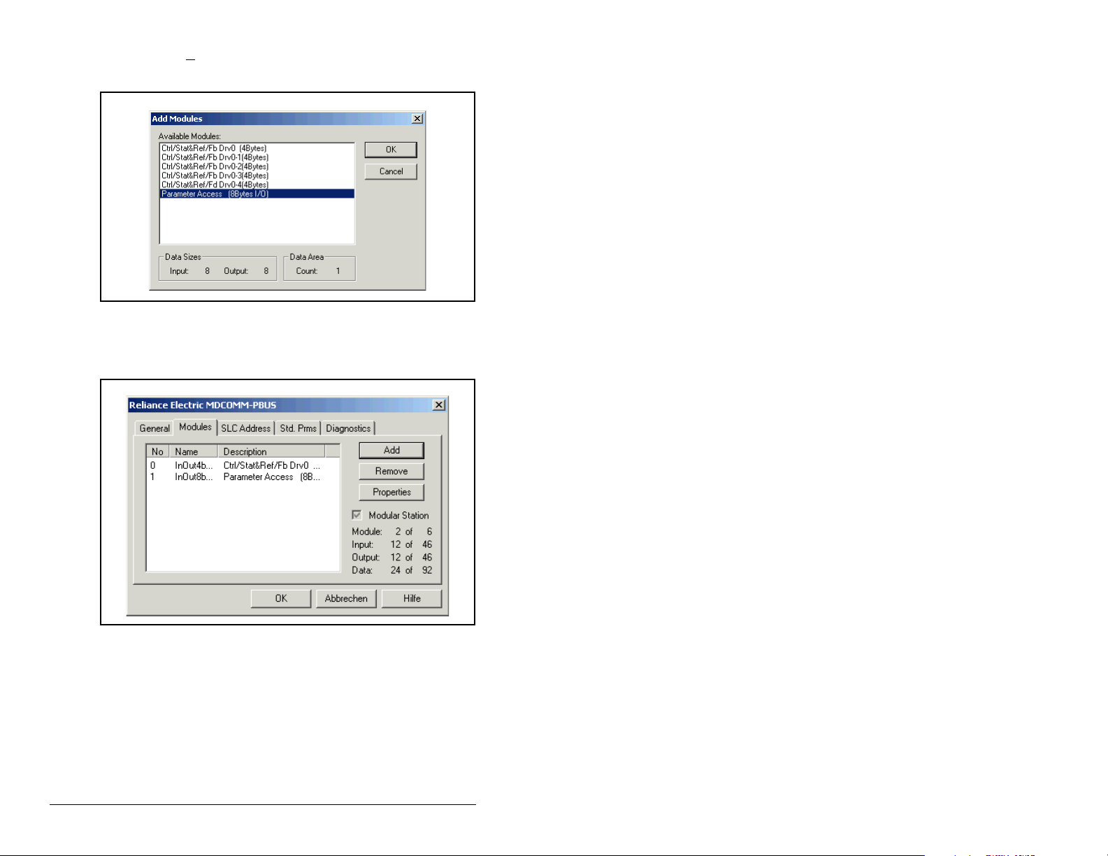
Step 12. Click Add to continue adding modules. Select “P arameter
Access” and click OK.
Figure 5.14 – Add Modules: Parameter Access Selection Window
Step 13. The “Parameter Access” module has now been added as
shown in figure 5.15.
Figure 5.15 – Modules: Parameter Access Viewing Window
Settings can be chosen to map Station models to SLC addresses.
In our example M1/Mo files are used for Input / Output.
Note that the Reference/Feedback (Ctrl/Stat & Ref/Fdbk) start at
word 0.
5-10 PROFIBUS Communications Module
Page 47
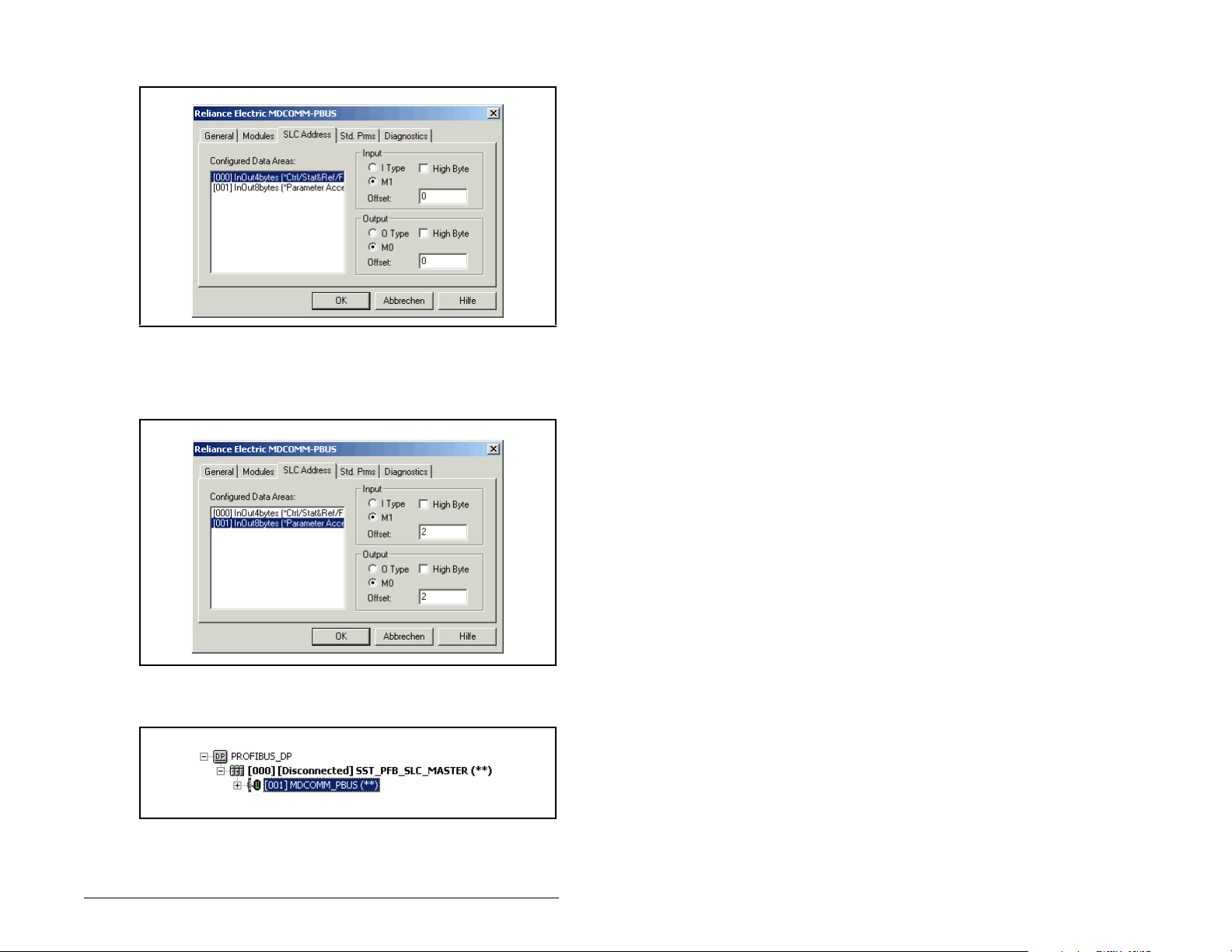
Step 14. Click on the SLC Address tab as shown in figure 5.16.
Figure 5.16 – SLC Address: M1/M0 (Ctrl/Stat & Ref/Fdbk)
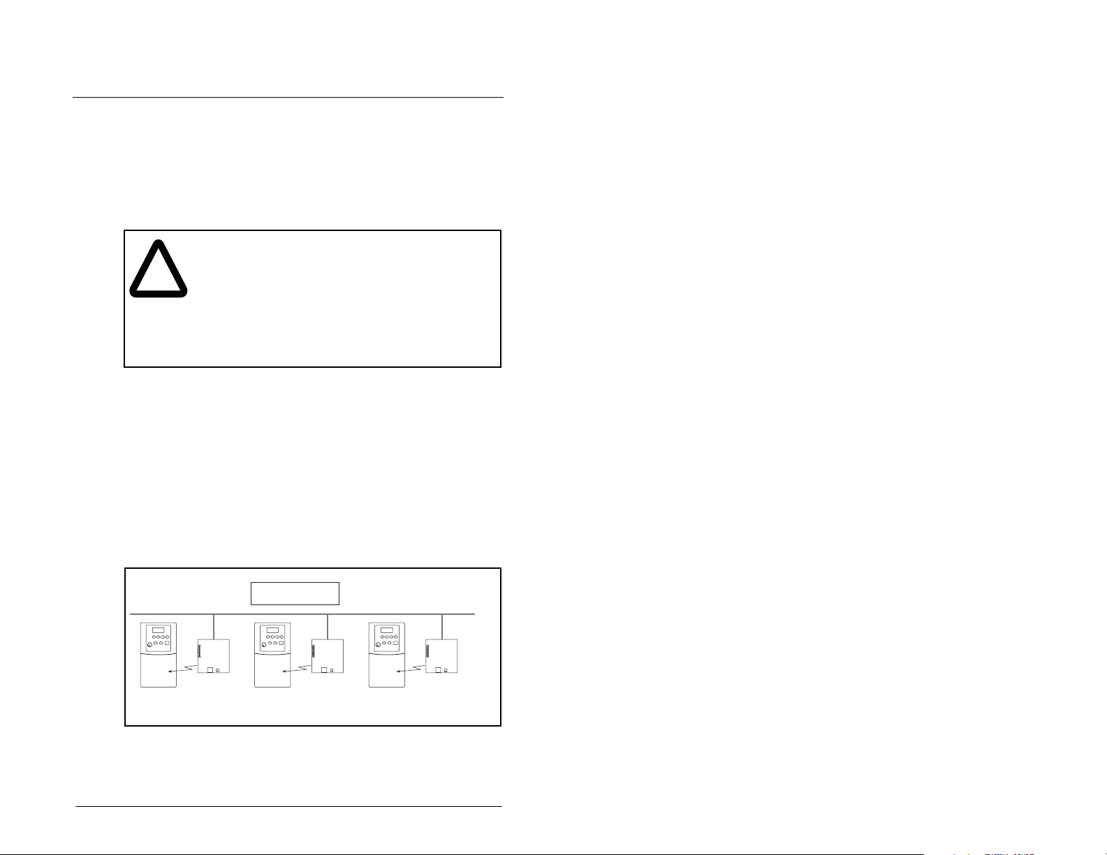
Step 15. Parameter Access starts at word 10 in the M1/M0 files.
Note that Parameter Access utilizes 4 words. Click OK
when finished.
Figure 5.17 – SLC Address: M1/M0 (Parameter Access)
Step 16. Station 1 is now displayed in the network window.
Figure 5.18 – Station 1 Network Window
Configuring the PROFIBUS Scanner 5-11
Page 48

Station 1 is configured as follows:
Table 5.2 – Station 1 Configurations
Module M1/M0 Word
Ctrl/Stat & Ref Fdbk Drive 0 0
Parameter Access 2
Note that Station 1 occupies 6 words.
Step 17. The same steps for configuring Station 1 will be used to
configure Station 2. Refer to previous steps (beginning
with step 9) for Configuring the SST-PFB-SLC PROFIBUS
Scanner Station 2. Refer to figure 5.19.
Figure 5.19 – Station 2 Network Window
Station 2 is configured as follows:
Table 5.3 – Station 2 Configurations
Module M1/M0 Word
Ctrl/Stat & Ref Fdbk Drive 0 6
Parameter Access 8
Note that Station 2 occupies 6 words.
Step 18. Use the null modem cable that came with the scanner to
connect COM1 on the PC and the CONFIG RS232 port
on the scanner.
Important:The processor needs to be in program mode before
proceeding.
Step 19. Right-click on the scanner in the network window and
select “Connect”. Then right-click again on the scanner in
the network window and select “Load Configuration”. If a
minimum cycle time attention window pops up, clic k OK to
continue. After the configuration has been loaded into the
5-12 PROFIBUS Communications Module
Page 49

scanner, “Configured Program” will be displayed in the
message window (see figure 5.20).
Figure 5.20 – Network Window Scanner Selection
Step 20. Click F
ile and Save As from the tool bar, as a unique File
N
ame. The configuration of the scanner is now complete.
Note that cycling power to the scanner is recommended.
See figure 5.21.
Figure 5.21 – Save As Dialog Window
Summary of the example scanner configuration:
M0 / M1 Addressing
Module
Station 1 Station 2
Logic Command / Status 0 6
Reference / Feedback 1 7
Parameter Access 2 8
Configuring the PROFIBUS Scanner 5-13
Page 50

5-14 PROFIBUS Communications Module
Page 51

CHAPTER 6
Using I/O Messaging
Chapter 6 provides information and examples that explain how to
use I/O Messaging to control an MD65 drive.
ATTENTION: The examples in this publication are
intended solely for purposes of example. There are
!
6.1 About I/O Messaging
I/O messaging is used to transfer the data which controls the MD65
drive and sets its Reference.
many variables and requirements with any
application. Rockwell Automation does not assume
responsibility or liability (to include intellectual
property liability) for actual use of the examples
shown in this publication. Failure to observe this
precaution could result in bodily injury or damage to
equipment.
The PROFIBUS module provides options for configuring and using
I/O, including the size of the I/O, which can be configured by
selecting the number or attached drives (Single or Multi-Drive
mode).
Chapter 4, Configuring the PROFIBUS Module, and chapter 5,
Configuring the PROFIBUS Scanner, discuss how to configure the
module and scanner on the network for these options. The Glossary
defines the different options. This chapter discusses how to use I/O
after you have configured the module and scanner.
6.2 Understanding the I/O Image
The terms input and output are defined from scanner’s point of
view. Therefore, Output I/O is data that is output from the scanner
and consumed by the PROFIBUS module. Input I/O is the data that
is produced by the module and consumed as input by the scanner.
Using I/O Messaging 6-1
Page 52

The I/O image table will vary based on the configuration of the
Mode Jumper (J2) on the module and MDI I/O Cfg (parameter 11).
The image table always uses consecutive words starting at word 0.
Figure Figure 6.1 illustrates an example of a drive I/O image (16-bit
words).
MDI
MD65 Drive
Logic Command
Reference
Logic Status
Feedback
Message
Handler
Controller
PROFIBUS
Scanner
Output
Image
(Write)
Input
Image
(Read)
Message
Handler
Figure 6.1 – Single Drive Example of I/O Image
Adapter
Word and I/O
0 Logic Command
1 Reference
0 Logic Status
1 Feedback
Message
Buffer
Single drive mode is the typical configuration, where one node
consists of a MD65 drive with a MDCOMM-PBUS module.
For Multi-Drive mode, where one node can consist of up to five
drives, refer to chapter 8, Using Multi-Drive mode.
6.3 Using Logic Command/Status
When enabled, the Logic Command/Status word is always word 0 in
the I/O image. The Logic Command is a 16-bit word of control
produced by the scanner and consumed by the module. The Logic
Status is a 16-bit word of status produced by the module and
consumed by the scanner.
This manual contains the bit definitions for compatible products
available at the time of publication in Appendix C, Logic Command/
Status Words. For other products, refer to their documentation.
6-2 PROFIBUS Communications Module
Page 53

6.4 Using Reference/Feedback
When enabled, Reference/Feedback alwa ys begins at word 1 in the
I/O image. The Reference (16 bits) is produced by the controller
and consumed by the module. The Feedback (16 bits) is produced
by the module and consumed by the controller.
Size Valid Values
16-bit 0.0 to 4000
1
In I/O Image Example
Word 1 Figure 6.1
0.0 to 240.0 Hz (MD60) or
0.0 to 400.0 Hz (MD65)
1
The Reference for a MD65 or MD60 is set in Hz. For example, “300”
equates to 30.0 Hz (the decimal point is always implied).
Using I/O Messaging 6-3
Page 54

6-4 PROFIBUS Communications Module
Page 55

CHAPTER 7
Using Explicit Messaging
(Parameter Protocol)
Chapter 7 provides information and examples that explain how to
use Explicit Messaging to monitor and configure the module and
connected MD65 drive, as well as other peripherals.
ATTENTION: The examples in this publication are
intended solely for purposes of example. There are
!
many variables and requirements with any
application. Rockwell Automation does not assume
responsibility or liability (to include intellectual
property liability) for actual use of the examples
shown in this publication. Failure to observe this
precaution could result in bodily injury or damage to
equipment.
ATTENTION: If Explicit Messages are programmed
to write parameter data to Non-Volatile Storage
(NVS) frequently , the NVS will quickly exceed its lif e
cycle and cause the drive to malfunction. Do not
create a program that frequently uses Explicit
Messages to write parameter data to NVS. Datalinks
do not write to NVS and should be used for frequently
changed parameters. Failure to observe this
precaution could result in damage to, or destruction
of, equipment.
7.1 About Explicit Messaging
Explicit Messaging is used to transfer data that does not require
continuous updates. With Explicit Messaging, you can configure
and monitor a slave device’s parameters on the PROFIBUS
network.
To be able to use the parameter protocols in the PROFIBUS
module, the Parameter Access module must be added to the
master configuration when configuring the network.
Using Explicit Messaging (Parameter Protocol) 7-1
Page 56

Refer to step 21 in chapter 5 to view the procedure for adding the
“Parameter Access” module to a configuration. This maps four
words input and output to the end of the I/O configuration, which is
used as the request/response in the parameter message format
(figure 7.2).
7.2 Running Explicit Messages
There are five basic events in the Explicit Messaging process
defined in figure 7.1. The details of each step will vary depending on
the controller. Refer to the documentation for your controller.
Important: There must be a request message and a response
Complete Parameter
Data Exchange
Retrieve Parameter
Data Exchange Response
message for all Explicit Messages, whether you are
reading or writing data.
Set up and send
Parameter Data
Format the required data and set up the ladder
logic program to send an Explicit Message request
to the scanner module (download).
The scanner module transmits the Explicit
Message Request to the slave device over the
PROFIBUS network.
The slave device transmits the Explicit Message
Response back to the master.
The controller retrieves the Explicit Message
Response.
The Explicit Message is complete.
Figure 7.1 – Explicit Message Process
7-2 PROFIBUS Communications Module
Page 57

7.3 Parameter Protocol
This protocol uses four words in the PROFIBUS I/O area. Requests
and responses are a handshake procedure and cannot be batched,
meaning that if the master sends a request, it has to wait for the
response before sending a new request.
With this protocol you can:
• Read 8-bit or 16-bit parameters from any MDI port
• Write 8-bit or 16-bit parameters to any MDI port
• Read the Module Fault Code
• Read Events
• Read Diagnostic Items
Request
Bit 15-12 11 10-0 15-12 11 10-0
Parameter Access
Word 1 (PCA)
Parameter Access
Word 2 (IND)
Parameter Access
Word 3 (PVA)
Parameter Access
Word 4 (PVA)
Refer to sections 7.3.1 and 7.3.2 for a description of the data that is
required in each word.
RC SPM PNU RC SPM PNU
Subindex Subindex
Spare Spare
Parameter value Parameter value
Figure 7.2 – Parameter Message Format
Response
Using Explicit Messaging (Parameter Protocol) 7-3
Page 58

7.3.1 Parameter Message Request
Table 7.1 – Parameter Message Request Data
Word Description
1 PNU - Parameter Number (Bit 0-10)
The parameter number determines which parameter to
access in the selected peripheral. Parameters 1-1023 can
be accessed.
Parameter numbers 1024 - 2047 are used to access the
fault object. Parameter 1024 is equal to the latest fault, 1025
to the prior fault, and so on.
Bit Definitions
1-1023 Parameters (Drive or Module)
1024 Module Fault Code
1025-1056 Module Events
1280-1289 Diagnostic Items (Single Drive)
1280-1304 Diagnostic Items (Multi-Drive)
SPM - Spontaneous Message (Bit 11)
Reserved - Should always be set to 0.
RC - Request/Response Code (Bit 12-15)
One of the following codes have to be used:
0 = No request
1 = Request parameter value
2 = Change parameter value (8-bit & 16-bit word)
3 = Spare
4 = Parameter minimum
5 = Parameter maximum
6 = Default Value
7 - 15 = Reserved
7-4 PROFIBUS Communications Module
Page 59

Table 7.1 – Parameter Message Request Data
Word Description
2 IND - Index
The IND is used to specify which drive will receive a
message.
0-2 bits = MDI port
Bit Definitions
000 Drive 0 single drive mode
001 Drives 0-1 multi-drive mode
010 Drives 0-2 multi-drive mode
011 Drives 0-3 multi-drive mode
101 Drives 0-4 multi-drive mode
3 - 15 = Reserved
3 PVA - Parameter value
Spare
4 PVA - Parameter value (8-bit & 16-bit word).
Read Request: Not used
Write Request: Contents the write value for a 8-bit or 16-bit
parameter.
7.3.2 Parameter Message Response
Table 7.2 – Parameter Message Response Data
Word Description
1 PNU - Parameter Number (Bit 0-10)
Requested parameter number.
SPM - Spontaneous Message (Bit 11)
Reserved - is always set to 0.
RC - Request/Response Code (Bit 12-15)
One of the following codes will be sent:
0 = No request
1 = Transfer parameter value (8-bit & 16-bit word)
2 = Spare
3-6 = Reserved
7 = Request rejected (including Module Fault Code and
Parameter Message Fault Code, see table below)
9-15 = Reserved
Using Explicit Messaging (Parameter Protocol) 7-5
Page 60

Table 7.2 – Parameter Message Response Data
Word Description
2 IND - Index
Port ID of requested parameter
3 PVA - Parameter value
Spare
4 PVA - Parameter value (8-bit & 16-bit word).
Read Response: Contents the value from a 8-bit or 16-bit
parameter or the Fault Code (if RC = 7).
Write Response: Confirms the write value for a 8-bit or 16bit parameter or the Fault Code (if RC = 7).
Table 7.3 – Module Fault Code
Fault Code Description
51 MDI Port watchdog
52 Profibus network loss
53 Not compatible product
54 MDI time-out or additional MDI master connected
Table 7.4 – Parameter Message Response Fault Numbers and Descriptions
Fault
Number Description
101 Service not supported (i.e., set service to a read-only
parameter)
102 Service not valid
104 Parameter does not exist (i.e., parameter
number>max number of parameters)
106 Data value out of range (i.e., set value is out of range)
107 State conflict (i.e., parameter is not changeable while
the product is in an operating state)
7-6 PROFIBUS Communications Module
Page 61
CHAPTER 8
Using Multi-Drive Mode
Chapter 8 provides information to explain how to use Multi-Drive
mode.
ATTENTION:The examples in this publication are
intended solely for purposes of example. There are
!
8.1 Single Mode vs. Multi-Drive Mode
The MDI interface provides a means to connect up to five drives on
one node daisy-chained over the RS-485. Two different operation
modes, single and multiple drive modes, are possible.
many variables and requirements with any
application. Rockwell Automation, Inc. does not
assume responsibility or liability (to include
intellectual property liability) for actual use of the
examples shown in this publication. Failure to
observe these precautions could result in bod il y
injury and/or damage to equipment.
Single mode is a typical network installation, where a single
Profibus node consists of a single drive with a MDCOMM-PBUS
module. In this mode, the module can talk to one host, and the host
can support one additional external peripheral (OIM or MDCOMM-
232) over MDI.
1 drive per node
Profibus
MD65 with
MDCOMM-PBUS
Figure 8.1 – Single Mode Example for Network
Using Multi-Drive Mode 8-1
MD65 with
MDCOMM-PBUS
MD65 with
MDCOMM-PBUS
Page 62

Figure 8.2 shows that the Single Drive mode provides the possibility
of connecting one additional external peripheral.
MDI
LANG DISP
Esc
PROG
7 8 9
4 5 6
1 2 3
.
DEL
ALT
JOG
0
+/-
LANG DISP
Prog
ALT
JOG
Figure 8.2 – MDI Peripheral Devices for Single Mode Connection
Multi-Drive mode is an alternative to the typical network installation,
where a single Profibus node can consist of one to five drives (see
figure 8.3). The first drive must be a MD65 with a MDCOMM-PBUS
module. The remaining drives can be MD65 or MD60 drives that are
daisy-chained over RS-485 with the first drive.
Profibus
MD65
up to 5 drives per node
Up to 4 MD65 or MD60 Drives
MDCOMM-PBUS
AK-U0-RJ45-TB2P
Connector with 3rd Party
Terminating Resistor
AK-U0-RJ45-TB2PRS-485
AK-U0-RJ45-TB2P
Connector with 3rd Party
Terminating Resistor
Figure 8.3 – Multi-Drive Mode Example for Network
8-2 PROFIBUS Communications Module
Page 63

The multiple drive connectivity, up to five drives with at least one
MD65 drive, for example , one MD65 and four MD60 drives, provides
a low cost Profibus solution in the industry for multiple drives.
Important: In Multi-Drive mode, the unit will not operate with MDI
peripheral devices such as the OIM or the MDCOMM232 and the application of any other peripheral will be
prohibited.
Benefits of Multi-Drive mode include:
• Lower hardware costs. Only one MDCOMM-PBUS module is
needed for up to five drives. The MD60 can also be used for the
daisy-chained drives instead of MD65 drives.
• Reduces the network node count. For example, in Single mode
30 drives would consume 30 nodes. In Multi-Drive mode, 30
drives can be connected in 6 nodes.
• Provides a means to put MD60 drives on Profibus (MD60 drives
do not have an internal communications module slot).
• Controller can control, monitor, and read/write parameters for all
five drives.
The trade-offs of Multi-Drive mode include:
• If the MD65 drive with the MDCOMM-PBUS module is powered
down, then communications with the daisy-chained drives is
disrupted and the drives will take the appropriate communications
loss action set in each drive.
• Communications throughput to the daisy-chained drives will be
slower than if each drive was a separate node on Profibus (Single
mode). This is because the MDCOMM-PBUS module must take
the Profibus data for the other drives and sequentially send the
respective data to each drive over RS-485.
• Since the RS-485 ports are used for daisy-chaining the drives,
there is no connection for a peripheral device such as an OIM.
The AK-U0-RJ45-SCI MDI Splitter Cable cannot be used to add a
connection for a peripheral device.
Using Multi-Drive Mode 8-3
Page 64

8.2 System Wiring
To daisy-chain the drives of the MD65 with the MDCOMM-PBUS
module (Drive 0), the AK-U0-RJ45-TB2P terminal block connector
(Figure 8.4) can be used for easy installation.
Figure 8.4 – AK-U0-RJ45-TB2P Terminal Block Connector
The wiring diagram for using AK-U0-RJ45-TB2P terminal block
connectors is shown in figure 8.5.
To
MD65 with
MDCOMM-PBUS
120
Ω
¼ Watt
Resistor
To
Drive #2
Figure 8.5 – Multi-Drive Mode Example for Network
To
Drive #3
To
Drive #4
To
Drive #5
Ω
120
¼ Watt
Resistor
The AK-U0-RJ45-TB2P comes with five (5) terminal block
connectors and two (2) terminating resistors.
8-4 PROFIBUS Communications Module
Page 65
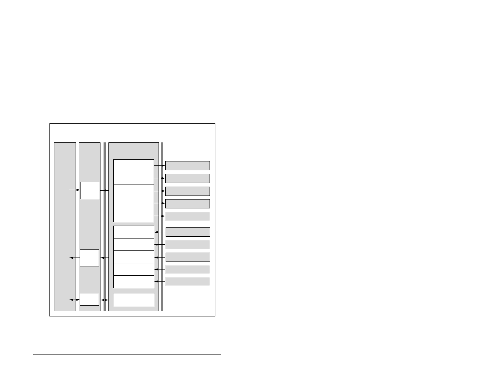
8.3 Understanding the I/O Image
The terms input and output are defined from the scanner’s point
of view. Therefore, Output I/O is data that is output from the
scanner and consumed by the Profibus module. Input I/O is status
data that is produced by the module and consumed as input by
the scanner. The I/O image table will vary based on the:
Configuration of the Mode Jumper (J2) on the module and MDI
I/O Cfg (parameter 11). The image table always uses consecutive
words starting at word 0.
Figure 8.6 illustrates the Multi-Drive I/O image with 16-bit words.
Controller
Profibus
Scanner Adapter
Output
Image
(Write)
Input
Image
(Read)
Message
Handler
Word and I/O
0 Logic Command
1 Reference
2 Logic Command
3 Reference
4 Logic Command
5 Reference
6 Logic Command
7 Reference
8 Logic Command
9 Reference
0 Logic Status
1 Feedback
2 Logic Status
3 Feedback
4 Logic Status
5 Feedback
6 Logic Status
7 Feedback
8 Logic Status
9 Feedback
Message
Buffer
MDI
MD65 Drive 0
MD65 Drive 0-1
MD65 Drive 0-2
MD65 Drive 0-3
MD65 Drive 0-4
MD65 Drive 0
MD65 Drive 0-1
MD65 Drive 0-2
MD65 Drive 0-3
MD65 Drive 0-4
Figure 8.6 – Multi-Drive Mode Example of I/O Image
Using Multi-Drive Mode 8-5
Page 66

8.4 Configuring the RS-485 Network
Table 8.1 shows the parameters that must be set in the daisychained drives.
Table 8.1 – Parameters for daisy-chained drives
Parameter Value
P36 (Start Source) 5 (RS485 (MDI) Port)
P38 (Speed Reference) 5 (RS485 (MDI) Port)
A103 (Comm Data Rate) 4 (“19.2K”)
A104 (Comm Node Addr) 1-247 (must be unique)
A107 (Comm Format) 0 (“RTU 8-N-1”)
Note: The RS-485 network is fixed at 19.2K baud, 8 data bits, no
parity, and 1 stop bit.
Important:Parameter A105 (Comm Loss Action) in the daisy-
Table 8.2 shows the Multi-Drive parameters that must be set in the
MDCOMM-PBUS.
Parameter Value
11 (MDI I/O Cfg) 0 = Drive 0 connected
17 (Drv 0 Addr) = Parameter A104 (Comm Node Address) in Drive 0
18 (Drv 1 Addr) = Parameter A104 (Comm Node Ad dress) in Drive 0-1
19 (Drv 2 Addr) = Parameter A104 (Comm Node Ad dress) in Drive 0-2
20 (Drv 3 Addr) = Parameter A104 (Comm Node Ad dress) in Drive 0-3
21 (Drv 4 Addr) = Parameter A104 (Comm Node Ad dress) in Drive 0-4
chained drives is still used in Multi-Drive mode. If the
RS-485 cable is disconnected or broken, the
disconnected drive(s) will immediately take the
corresponding Comm Loss Action(s). Parameter A106
(Comm Loss Time) is not used in Multi-Drive mode. On
the Profibus, Comm Flt Action (parameter 09) and Idle
Flt Action (parameter 10) in the MDCOMM-PBUS
determine the action taken for ALL of the drives on the
Multi-Drive node.
Table 8.2 – Parameters for MDCOMM-PBUS
1 = Drives 0-1 connected
2 = Drives 0-2 connected
3 = Drives 0-3 connected
4 = Drives 0-4 connected
After setting the MDCOMM-PBUS parameters, set the Module
Mode Jumper from Single drive operation to Multi-Drive operation,
and reset the module or cycle power.
8-6 PROFIBUS Communications Module
Page 67

Important: MDCOMM-PBUS parameters can be set using MDI
peripheral (OIM, V*S Utilities with MDCOMM-232,
etc.) ONLY when the Mode Jumper is in Single mode
position.
8.5 Multi- Mode Explicit Messaging
Parameter addressing for Explicit messaging in Multi-Drive is similar
to that in Single mode.
The parameter numbers range from 1 to 2047. Parameter numbers
1-1023 are used to access the drive or module parameters.
Parameter numbers 1024-2047 are used to access the Module
Fault Codes, Events and Diagnostic Items.
For example, to access Accel Time (parameter 39) f or Drive 0, Drive
0-1 to Drive 0-4 in Multi-Drive mode:
Table 8.3 – Accessing Accel Time (Parameter 39)
Module
Drive 0 Single Drive 000 39
Drives 0-1 Multi Drive 001 39
Drives 0-2 Multi Drive 010 39
Drives 0-3 Multi Drive 011 39
Drives 0-4 Multi Drive 100 39
8.6 Additional Information
• When the MD65 with the MDCOMM-PBUS module (Drive 0) is
powered up, all configured daisy-chained drives must be present
before an I/O connection is allowed on Profibus (i.e. before the
drives can be controlled).
• If the MD65 with the MDCOMM-PBUS module (Drive 0) is
powered down, communications with the four daisy-chained
drives (Drives 0-1 to Drives 0-4) are disrupted and the drives will
fault.
• If any of the daisy-chained drives (Drive 0-1 to Drive 0-4) are
powered down, the respective Input Image (Logic Status and
Feedback) sent to the scanner will be zeros, and the NET A and
DRIVE LEDs on the MDCOMM-PBUS module will flash red.
Status information from the scanner will not indicate there is a
fault at the node.
IND
(0-2 bits)
Parameter
Number
Using Multi-Drive Mode 8-7
Page 68

8-8 PROFIBUS Communications Module
Page 69

CHAPTER 9
Troubleshooting the
PROFIBUS Module and
Network
Chapter 9 contains information for troubleshooting the PROFIBUS
module and the network.
9.1 Understanding the Status Indicators
The PROFIBUS module has three status indicators. They can be
viewed on the module or through the drive cover. (See figure 9.1.)
➊
➋
➌
DRIVE
MS
NET A
NET B
Status
Number
Troubleshooting the PROFIBUS Module and Network 9-1
Indicator Description Refer to...
DRIVE MDI Connection Status Section 9.1.1
MS Module Status Section 9.1.2
NET A PROFIBUS Status Section 9.1 .3
NET B Not used N/A
Figure 9.1 – Status Indicators (Location on Drive May Vary)
➊
➋
➌
➍
Page 70

9.1.1 DRIVE Status Indicator
Table 9.1 – DRIVE Status Indicator: State Definitions
Status Cause Corrective Action
Off The module is not
powered or is not
connected properly to
the drive.
Flashing
Red
Solid
Red
Flashing
Green
Solid
Green
Solid
Orange
Flashing
Orange
The module is not
receiving a ping
message from the
drive.
The drive has refused
an I/O connection from
the module.
Another MDI peripheral
is using the same MDI
port as the module.
Not Used
The module is properly
connected and is
communicating with the
drive.
The module is booting. Wait until boot program is
The module is in flash
mode (SW8 down).
Application Failure
• Securely connect the module
to the drive using the ribbon
cable.
• Apply power to the drive.
• V erify that cables are
securely connected.
• Cycle power to the drive.
Important: Cycle power to the
product after making following
correction:
• Verify that all MDI cables on
the MD65 drive are securel y
connected and not damaged.
Replace cables if necessary.
• Check the Events, replace
the module with a compatible
Reliance Electric branded
product (MDCOMM-PBUS).
• No action.
complete.
• Wait until Firmware Update
is complete, then switch
SW8 to 1.
• Download Application code.
9-2 PROFIBUS Communications Module
Page 71

9.1.2 MS Status Indicator
Table 9.2 – MS Status Indicator: State Definitions
Status Cause Corrective Action
Off The module is not
powered.
Flashing
Red
Solid
Red
Flashing
Green
Solid
Green
The module has
faults or a drive is
missing in MultiDrive mode.
The module has
failed the hardware
test.
The module is
operational but is not
transferring I/O data.
The module is
operational and
transferring I/O data.
• Securely connect the module
to the MD65 drive using the
ribbon cable.
• Apply power to the drive.
• Clear faults in the drive.
• Disconnect additional MDI
peripheral and cycle power to
the drive.
• If cycling power does not
correct the problem, the
parameter settings may have
been corrupted. Reset defaults
and reconfigure the module.
• If resetting defaults does not
correct the problem, flash the
module with the latest firmware
release.
• For Multi-Drive mode,
determine which drive is
missing or faulted. Check
cabling and configuration
settings.
• Cycle power to the drive.
• Replace the module.
• Place the scanner in RUN
mode.
• Configure the module for the
program in the controller.
• Program the controller to
recognize and transmit I/O to
the module.
• No action.
Troubleshooting the PROFIBUS Module and Network 9-3
Page 72

9.1.3 NET A Status Indicator
Table 9.3 – NET A Status Indicator: State Definitions
Status Cause Corrective Actions
Off The module is not
powered or is not
connected properly
to the network or the
Node Address is
wrong.
Flashing
Red
Solid
Red
Flashing
Green
Solid
Green
Error in PROFIBUS
configuration.
Not Used.
Not Used.
The module is
properly connected
and communicating
on the network.
• Securely connect the module to
the drive using the Internal
Interface cable and to the
network using a PROFIBUS
cable. (Screw D-shell to the
module.)
• Check the SW8 of DIP-
Switches and set it to one Normal operating state.
• Check the DIP-Switches (SW1-
SW7) node address and the
Scanner setting.
• Apply power to the drive.
• Re-configure the PROFIBUS
module.
• No action required.
Important:For the Multi-Daisy mode, disconnecting a MDI cable
from a daisy-chained drive does not cause an error. The
module has no indication that the drive has been
removed, except that commands to the missing drive
have no effect.
9-4 PROFIBUS Communications Module
Page 73

9.2 Module Diagnostic Items in Single
Drive Mode
Table 9.4 lists diagnostic items that can be accessed using
V*S Utilities software or the LCD OIM.
Table 9.4 – Module Diagnostic Items for Single Drive Mode
No. Event Description
1 Field Flash Cnt The number of Firmware Updates.
2 Module Events The number of events in the event queue.
3 Reference Reference from PROFIBUS returned to MDI drive.
4 Logic Cmd Command from PROFIBUS returned to MDI drive.
5 Logic Sts Status of the drive returned to PROFIBUS.
6 Feedback Feedback from drive returned to PROFIBUS.
7PROFIBUS Rx
Errors
8PROFIBUS Tx
Errors
9 Data Rate Current setting of the PROFIBUS baud rate.
10 Node Address Current setting of the module Node address switch.
Current value of the PROFIBUS Receive Error
Counter register.
Current value of the PROFIBUS Transmit Error
Counter register.
9.3 Module Diagnostic Items in MultiDrive Mode
For the Multi-Drive mode it is not possible to connect a peripheral
device such as an OIM or MDCOMM-232 (V*S Utilities). Table 9.5
lists diagnostic items that can only be accessed via Profibus
network in Multi-Drive mode.
Table 9.5 – Module Diagnostic Items for Multi-Drive Mode
No. Event Description
1 Field Flash Cnt The number of Firmware Updates.
2 Module Events The number of events in the event queue.
3 Drv 0 Reference Reference from Profibus returned to MDI Drive 0.
4 Drv 0 Logic Cmd Command from Profibus returned to MDI Drive 0.
5 Drv 0 Logic Sts Status of the Drive 0 returned to Profibus.
6 Drv 0 Feedback Feedback from Drive 0 returned to Profibus
7 Drv 1 Reference Reference from Profibus returned to MDI Drives 0-1.
8 Drv 1 Logic Cmd Command from Profibus returned to MDI Drive s0-1.
9 Drv 1 Logic Sts Status of the Drives 0-1 returned to Profibus.
Troubleshooting the PROFIBUS Module and Network 9-5
Page 74

Table 9.5 – Module Diagnostic Items (Continued)for Multi-Drive Mode
No. Event Description
10 Drv 1 Feedback Feedback from Drives0-1 returned to Profibus
11 Drv 2 Reference Reference from Profibus returned to MDI Drives 0-2.
12 Drv 2 Logic Cmd Command from Profibus returned to MDI Drives 0-2.
13 Drv 2 Logic Sts Status of the Drives 0-2 returned to Profibus.
14 Drv 2 Feedback Feedback from Drives 0-2 returned to Profibus
15 Drv 3 Reference Reference from Profibus returned to MDI Drives 0-3.
16 Drv 3 Logic Cmd Command from Profibus returned to MDI Drives 0-3.
17 Drv 3 Logic Sts Status of the Drives 0-3 returned to Profibus.
18 Drv 3 Feedback Feedback from Drives 0-3 returned to Profibus
19 Drv 4 Reference Reference from Profibus returned to MDI Drives 0-4.
20 Drv 4 Logic Cmd Command from Profibus returned to MDI Drives 0-4.
21 Drv 4 Logic Sts Status of the Drives 0-4 returned to Profibus.
22 Drv 4 Feedback Feedback from Drives 0-4 returned to Profibus
23 Profibus Rx
Errors
24 Profibus Tx
Errors
25 Active drives
Current value of the Profibus Receive Error Counter
register.
Current value of the Profibus Transmit Error Counter
register.
The number of active slave drives.
number
9-6 PROFIBUS Communications Module
Page 75

9.4 Viewing and Clearing Events
The module maintains an event queue that reports the history of its
actions. You can view the event queue using an LCD OIM or
VS Utilities software.
Figure 9.2 – Viewing and Clearing Events Using an LCD OIM
Events
Many events in the event queue occur under normal operation. If
you encounter unexpected communications problems, the events
may help you or Reliance Electric personnel troubleshoot the
problem. Table 9.6 lists events that may appear in the event queue.
Table 9.6 – Event Codes and Descriptions
Code Event Description
0 No Event Text displayed in an empty event queue entry.
1 EEPROM Sum Flt Startup sequence detected corrupt EEPROM
storage in the module.
2 Slave Detected A MDI slave wa s detected on the slav e I/O line.
3 Slave Removed A MDI slave was removed on the slave I/O
line.
7 Bad I/O Config The actual connected drives are different from
I/O configuration (parameter 11).
8 Host Timeout Parameter data to a Drive Host timed out
waiting for a response.
9 Slave Timeout Parameter data to a Slave time out waiting for
a response.
10 Bad Host Flt The module was connected to an incompatible
device.
Troubleshooting the PROFIBUS Module and Network 9-7
Page 76

Table 9.6 – Event Codes and Descriptions
Code Event Description
11 MDI Bus Off Flt A bus-off condition was detected on MDI. This
event may be caused by loose or broken
cables or by noise.
13 P-DP Idle The PROFIBUS Module received a Network
Clear from the PROFIBUS Master.
14 P-DP Online The PROFIBUS Module has gone on-line the
PROFIBUS network.
15 P-DP Offline The PROFIBUS Module has gone off-line the
PROFIBUS network.
17 MDI Fault Msg The Host Faulted.
18 MDI Fault Clear The user cleared a fault in the module.
19 Not COMM Flt Th e module detected a fault condition on the
Profibus network.
21 Program Damage The checksum of the program is wrong.
9-8 PROFIBUS Communications Module
Page 77

Communications
Network
Protocol
Data Rates
Drive
Protocol MDI
Electrical
Drive
Network
Mechanical
Dimensions
Height
Length
Width
APPENDIX A
Technical
Specifications
PROFIBUS
9.6 kpbs, 19.2 kpbs, 93.75 kpbs, 187.5 kpbs,
500 kpbs, 1.5 Mbps, 3 Mbps, 6 Mbps, 12
Mbps. The module has auto baud rate
detection.
370 mA at 5 V supplied through the drive.
19 mm (0.75 in)
86 mm (3.39 in)
78.5 mm (3.09 in)
Weight 57 g (2 oz)
Technical Specifications A-1
Page 78

Environmental
Temperature
Operating
Storage
-10 to +50°C (14 to 149°F)
-40 to +85°C (-40 to 185°F)
Relative Humidity
Vibration
Shock
Altitude
-5 to 95% non-condensing
1.0 G Operational
2.5 G Non-operational
15.0 G Operational
30.0 G Non-operational
1,000m (3,300 ft.) without derating
Regulatory Compliance
Certification Specification
UL UL508C
CE EN50178 and EN61800-3
A-2 PROFIBUS Communications Module
Page 79

APPENDIX B
PROFIBUS Module
Parameters
The following information is provided for each PROFIBUS module
parameter along with its description:
Parameter Number: Unique number assigned to each
parameter.
Parameter Name: Unique name assigned to each
parameter.
Range: Predefined parameter limits or
selections.
Default: Factory default setting.
Type: Read Only or Read/Write
Reset Required: Module must be reset before parameter
The parameters in the PROFIBUS module are numbered
sequentially. However, depending on the configuration tool used,
they may have different numbers.
value is recognized.
PROFIBUS Module Parameters B-1
Page 80

1 Mode
Range: 0 = Single Drive
Default: N/A
Type: Read Only
Reset Required: N/A
Displays the Single or Multi-Drive operating mode selected with the
jumper J2 on the module.
1 = Multiple Drive
4P-DP Addr Actual
Range: 0 to 125
Default: N/A
Type: Read Only
Reset Required: N/A
Displays the PROFIBUS node address actually used by the module.
5 P-DP Rate Actual
Range: 0 = 9.6 kpbs
Default: N/A
Type: Read Only
Reset Required: N/A
Displays the PROFIBUS actual operating data rate.
1 = 19.2 kpbs
2 = 45.45 kpbs
3 = 93.75 kpbs
4 = 187.5 kpbs
5 = 500 kpbs
6 = 1.5 Mbps
7 = 3 Mbps
8 = 6 Mbps
9 = 12 Mbps
10 = Off-line
B-2 PROFIBUS Communications Module
Page 81

8 Reset Module
Range: 0 = Ready (No action)
Default: 0 = Ready
Type: Read/Write
Reset Required: No
No action if set to “Ready.” Resets the module if set to “Reset
Module.” Restores the module to factory default settings if set to
“Set Defaults.” This parameter is a command. It will be reset to
“0 = Ready” after the command has been performed.
1 = Reset Module
2 = Set Defaults (Restores module to factory-default
settings)
ATTENTION: If the module is transmitting I/O that
controls the drive, the drive may fault when you reset
!
the module. Determine how your drive will respond
before resetting a connected module. Failure to
observe this precaution could result in bodily injury
or damage to equipment.
9 Comm Flt Action
Range: 0 = Fault
Default: 0 = Fault
Type: Read/Write
Reset Required: No
Sets the action that the module and drive take if the module detects
that PROFIBUS communications have been disrupted. This setting
is effective only if I/O that controls the drive is transmitted though
the module.
1 = Stop
2 = Zero Data
3 = Hold Last
4 = Send Flt Cfg
ATTENTION: Comm Flt Action (parameter 9) and
Idle Flt Action (parameter 10) lets you determine the
!
PROFIBUS Module Parameters B-3
action of the module and connected drive if
communications are disrupted. By default, this
parameter faults the drive. You can set this
parameter so that the drive continues to run. Take
precautions to ensure that the setting of this
parameter does not create a hazard of injury or
equipment damage. Failure to observe this
precaution could result in bodily injury or damage to
equipment.
Page 82

10 Idle Flt Action
Range: 0 = Fault
Default: 0 = Fault
Type: Read/Write
Reset Required: No
Sets the action that the module and the drive take if the module
detects that the scanner is idle because the controller was switched
to program mode. This setting is effective only if the I/O that controls
the drive is transmitted through the module.
1 = Stop
2 = Zero Data
3 = Hold Last
4 = Send Flt Cfg
ATTENTION: Idle Flt Action (parameter 10) lets you
determine the action of the module and connected
!
drive if the scanner is idle. By default, this parameter
faults the drive. You can set this so that the drive
continues to run. Ensure that the setting of this
parameter does not create a hazard of injury or
equipment damage. Failure to observe this
precaution could result in bodily injury or damage to
equipment.
11 MDI I/O Cfg
Range: 0 = Drive 0
Default: 0
Type: Read/Write
Reset Required: Yes
Sets the configuration of the Drives that are active in the Multi-Drive
mode. Identifies the connections that would be attempted on a reset
or power cycle.
1 = Drives 0-1
2 = Drives 0-2
3 = Drives 0-3
4 = Drives 0-4
B-4 PROFIBUS Communications Module
Page 83

12 MDI I/O Actual
Range: 0 = Drive 0
Default: N/A
Type: Read Only
Reset Required: N/A
Displays the Drives that are active in the Multi-Drive mode.
1 = Drives 0-1
2 = Drives 0-2
3 = Drives 0-3
4 = Drives 0-4
13 Flt Cfg Logic
Range: 0000 0000 0000 0000 to 1111 1111 1111 1111
Default: 0000 0000 0000 0000
Type: Read/Write
Reset Required: No
Sets the Logic Command data that is sent to the drive if the
followi n g is true:
• Comm Flt Action (parameter 9) is set to Send Flt Cfg and
communications are disrupted.
• Idle Flt Action (parameter 10) is set to Send Flt Cfg and the
scanner is put into Program mode.
The bit definitions will depend on the product to which the module is
connected.
14 Flt Cfg Ref
Range: 0 to 4000
Default: 0
Type: Read/Write
Reset Required: No
Sets the Reference data that is sent to the drive if any of the
followi n g is true:
• Comm Flt Action (parameter 9) is set to Send Flt Cfg and
communications are disrupted.
• Idle Flt Action (parameter 10) is set to Send Flt Cfg and the
scanner is put into Program mode.
Important: If the drive uses a 16-bit Reference, the most significant
word of this value must be set to zero (0) or a fault will
occur.
PROFIBUS Module Parameters B-5
Page 84

Drv 0 Addr
17
Drv 1 Addr
18
Drv 2 Addr
19
Drv 3 Addr
20
Drv 4 Addr
21
Range: 1 - 125
Default: Drv 0 Addr = 1
Drv 1 Addr = 2
Drv 2 Addr = 3
Drv 3 Addr = 4
Drv 4 Addr = 5
Type: Read/Write
Reset Required: Yes
Sets the corresponding node addresses of the daisy-chained drives
when the module Mode Jumper (J2) is set for Multi-Drive operation.
Important: The settings for these parameters must match the
Comm Node Addr (parameter A104) settings in the
respective drives. Each setting must also be unique (no
duplicate node address).
24 P-DP State
Range: 0 = WAIT_PRM
Default: N/A
Type: Read Only
Reset Required: N/A
1 = WAIT_CFG
2 = DATA_EX
3 = ERROR
Displays the state of the PROFIBUS controller.
B-6 PROFIBUS Communications Module
Page 85

Appendix C provides the definitions of the Logic Command/Logic
Status words that are used for some products that can be
connected to the PROFIBUS module. If you do not see the Logic
Command/Logic Status for the product that you are using, refer to
your product’s documentation.
C.1 MD65 Drives
Logic Command Word
APPENDIX C
Logic Command/
Status Words
15 14 13 12 11 10 9876543210Command Description
xxx Reference
xMOP
1
A 0 = Not Stop condition (logic 0) must first be present before a 1 = Start condition will start the
drive.
Logic Bits
x Stop 0 = Not Stop
x
Start
x Jog 0 = Not Jog
x Clear Faults 0 = Not Clear Faults
x x Direction 00 = No Command
x Not Used
xMOP
x x Accel Rate 00 = No Command
x x Decel Rate 00 = No Command
Increment
Select
Decrement
1 = Stop
1
0 = Not Start
1 = Start
1 = Jog
1 = Clear Faults
01 = Forward Command
10 = Reverse Command
11 = Change Direction (toggle)
0 = Not Increment
1 = Increment
01 = Accel Rate 1 Command
10 = Accel Rate 2 Command
11 = Hold Accel Rate
01 = Decel Rate 1 Command
10 = Decel Rate 2 Command
11 = Hold Decel Rate
000 = No Command
001 =Freq Source = Select
010 = Freq Source = Int. Freq
011 = Freq Source = Comm
100 = Preset Freq 1
101 = Preset Freq 2
110 = Preset Freq 3
111 = Preset Freq 4
0 = Not Decrement
1 = Decrement
Logic Command/Status Words C-1
Page 86

Logic Status Word
15 14 13 12 11 10 9876543210 Status Description
Logic Bits
x Ready 0 = Not Ready
1 = Ready
x Active 0 = Not Active
1 = Active
x Command
x Actual
Direction
Direction
0 = Reverse
1 = Forward
0 = Reverse
1 = Forward
x Accel 0 = Not Accelerating
1 = Accelerating
x Decel 0 = Not Decelerating
x Alarm 0 = No Alarm
1 = Decelerating
1 = Alarm
x Fault 0 = No Fault
1 = Fault
x At Speed 0 = Not At Reference
x Main Freq 0 = Not Controlled By Comm
x Operation
Command
1 = At Reference
1 = Controlled By Comm
0 = Not Controlled By Comm
1 = Controlled By Comm
x Parameters 0 = Not Locked
1 = Locked
x Digital Input
x Digital Input
x Digital Input
x Digital Input
1
This status is available only with firmware revision 2.0 and higher.
1 Status
2 Status
3 Status
4 Status
1
1
C-2 PROFIBUS Communications Module
Page 87

APPENDIX D
SLC Ladder Logic
Examples
Appendix D provides examples that explain how to use a SLC
controller to send I/O Messaging to control, configure, and monitor
an MD65 drive in Single Drive and Multi-Drive mode.
SLC Ladder Logic Examples D-1
Page 88
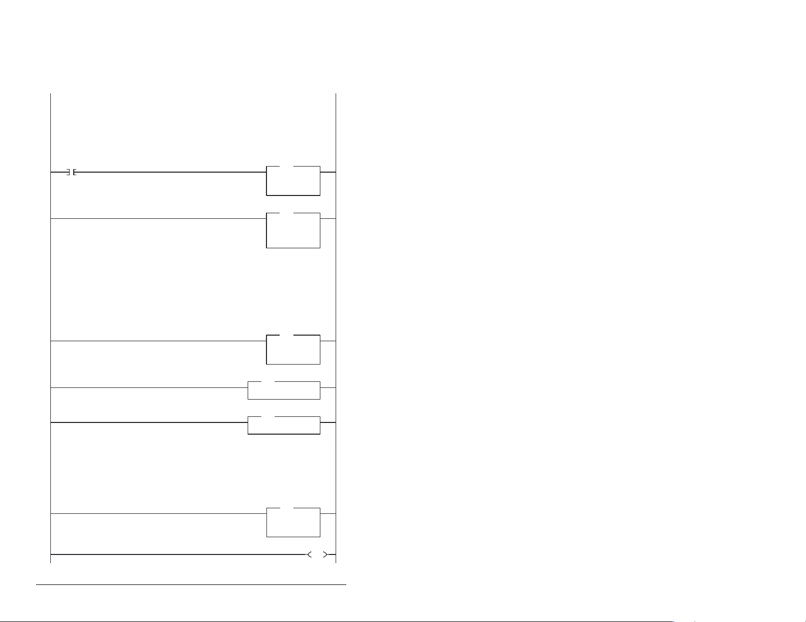
D.1 Single Drive Example
D.1.1 Main Routine
This example program is for a PROFIBUS demonstration using a SLC 5/04
(
SST-PFB-SLC) in the first slot of the rack. The program is written for 2 drives on the network:
Station 1 MD65 with MDCOMM-PBUS
Station 2 MD65 with MDCOMM-PBUS
The example program demonstrates using Logic Command / Reference, Logic Status / Feedback and Parameter
Access using the Parameter Protocol.
On power-up, zero out the transmitt buffer to the Scanner.
First Pass
S:1
0
15
Automatically have the SST-PFB-SCL scanner's watchdog period track that of the
SCL processor (recommended per SST user manual)
1
The Scanner is configured to 12 bytes (6 words) of inputs for each drive. Two drives require 24 bytes (12 words).
Read the drives data from the Profibus scanner.
File N10: contains the acutal read data that can be used elsewhere in the ladder program.
Station 1 Station 2 Description
M1:1.0 (N10:0) M1:1.6 (N10:6) Logic Status
M1:1.1 (N10:1) M1:1.7 (N10:7) Speed Feedback
M1:1.2 (N10:2) M1:1.8 (N10:8) Parameter Protocol Word 1 (PCA)
M1:1.3 (N10:3) M1:1.9 (N10:9) Parameter Protocol Word 2 (IND)
M1:1.4 (N10:4) M1:1.10 (N10:10) Parameter Protocol Word 3 (PVA 1)
M1:1.5 (N10:5) M1:1.11 (N10:11) Parameter Protocol Word 4 (PVA 2)
2
Execute LAD 3 - Station 1 Drive Logic
3
processor
with an SST Profibus scanner
JSR
JSR
Jump To Subroutine
SBR File Number U:3
FLL
FLL
Fill File
Source 0
Dest #N20:0
Length 12
MOV
MOV
Move
Source S:3
Dest M0:1.4011
COP
COP
Copy File
Source #M1:1.0
Dest #N10:0
Length 12
2561<
?<
Execute LAD 4 - Station 2 Drive Logic
4
Write the drives' data to the profibus scanner.
File N20: contains the actual write data generated elsewhere in the ladder program.
Station 1 Station 2 Description
M0:1.0 (N20:0) M0:1.6 (N20:6) Logic Command
M0:1.1 (N20:1) M0:1.7 (N20:7) Speed Reference
M0:1.2 (N20:2) M0:1.8 (N20:8) Parameter Protocol Word 1
M0:1.3 (N20:3) M0:1.9 (N20:9) Parameter Protocol Word 2 (IND)
M0:1.4 (N20:4) M0:1.10 (N20:10) Parameter Protocol Word 3 (PVA1)
M0:1.5 (N20:5) M0:1.11 (N20:11)
5
6
Parameter Protocol Word 4 (PVA2)
(PCA)
JSR
JSR
Jump To Subroutine
SBR File Number U:4
COP
COP
Copy File
Source #N20:0
Dest #M0:1.0
Length 12
END
D-2 PROFIBUS Communications Module
Page 89
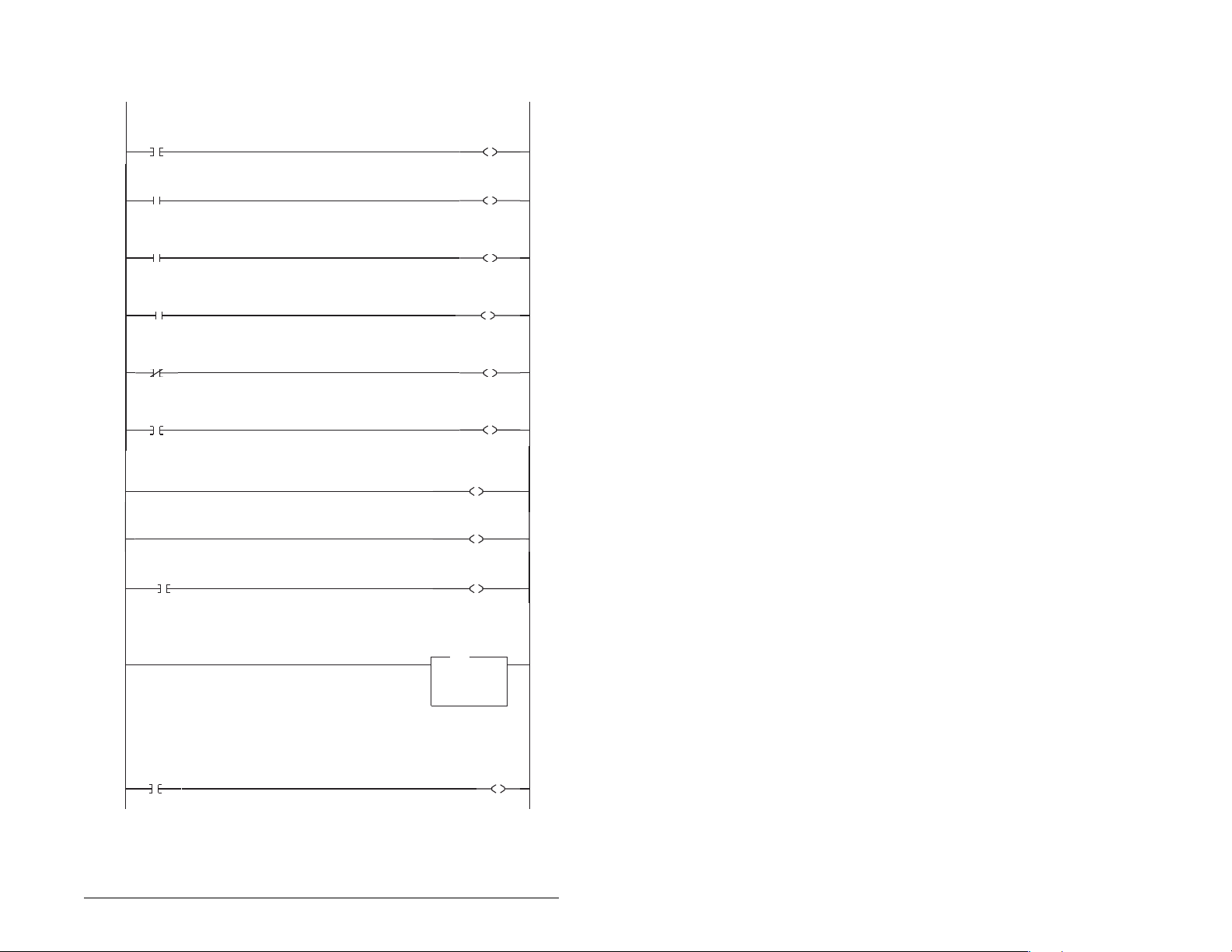
D.1.2 Drive 0 Control/Reference/Parameter Access
Routine
Controlling the Logic Command word in the drive. B3:20/* bits are controlled elsewhere in the user program.
Station 1
Stop
Command
0
B3:20
0
Station 1
Start
Command
B3:20
1
1
Station 1
Jog
Command
B3:20
2
2
Station 1
Clear Faults
Command
B3:20
3
3
Station 1
Reverse
Command
B3:20
4
4
Station 1
Reverse
Command
05B3:2
4
c e over the Profibus, the e ReferenceTo ontrol the speed referenc thre Select bits (bits 14-12) need to have the values 011.
6
7
"Never Closed"
B3:20
8
5
Station 1 Speed Reference
The MD65 Speed Reference (parameter 38) needs to be set to 5 ("RS485 [MDI] Port").
N19:1 is controlled elsewhere in the user program.
9
This section of the outine is only needed if the application needs to perform Parameter Protocol Reads or Writes to Station 1.
On power-up, initialize the Parameter Protocol routine.
Fi t Pass
10
r
rs
S:1
15
Station 1
Logic Command
STOP
Station 1
Logic Command
START
Station 1
Logic Command
JOG
Station 1
Logic Command
CLEAR FAULTS
Station 1
Logic Command
FORWARD
Station 1
Logic Command
REVERSE
Station
mand
om
Logic C
REFERENC
N20:0
12
Station 1
Logic Command
REFERENCE SELECT 1
N20:0
13
Station 1
Logic Command
REFERENCE SELECT 2
N20:0
14
Station 1
Speed Reference
Write
MOV
MOV
Move
Source N19:1
Dest N20:1
N20:0
0
N20:0
1
N20:0
2
N20:0
3
N20:0
4
N20:0
5
ESELECT0
273<
273<
Station 1
Par Prot
Messaging
Request
B3:19
U
15
SLC Ladder Logic Examples D-3
Page 90

This circuit utilizes the Param eter Protocol. A REQUEST to Station 1 is processed only one at a time, and after each
RESPONSE from Station 1 a zero must be sent and received to 'handshake' before the next REQUEST/RESPONSE
transaction can take place. For example:
Send a param. read request --> Receive a parameter read response -->Send a "0" --> Receive a "0" --> [Transaction compl.]
If the RESPONSE PCA Word 1 (N10:2) is "0", then a REQUEST can be initiated.
Elsewhere in the user program these words must be loaded with messagedata prior to initiating the REQUEST.
N7:10 = RC = the operation to be performed("1" = Read, "2" = 16-bit Write),
N7:11 = PNU = the parameter number to read or write
N7:12 = SubIndex = the MDI port # ("0" = Host or MD65 drive, "5" = MDCOMM-PBUS, etc.)
N7:13 = PVA #1 (the parameter value (high word)) - only used when writing parameters
N7:14 = PVA #2 (the parameter value (low word)) - only used when writing parameters
The four Parameter Protocol Words set up in thescanner are used to perform the Parameter Protocol:
N20:2 = contains RC (the operation to be performed) and PNU (the parameter number to read or write) combined
N20:3 = Subindex (the MDIport #)
N20:4 = P
N20:5 = PVA #2 (the parametervalue (low word))
B3:19/15 is turned ON elsewhere in the program after a REQUEST message (N7:10-14) is loaded. This causes one Param.
Protocol read or write to occur and B3:19/15 is turned OFF when the transaction is complete.
Station 1
Par Prot
Messaging
Request
B3:19
11
N10:2 is the Station 1 Response Parameter Access Word 1. It is <> 0 when a message has been received in response to a
message request. If the response is >= 7000 hex(28672 decimal), then the adapter is responding that an error has occured.
In this case, the returned data in the response will contain a fault code and not the parameter value data.
The response message can be found at:
N7:20 = PCA Word = contains RCand PNU
N7:21
= SubIndex = the MDI port # ("0" = Host or MD65 drive, "5" = MDCOMM-PBUS, etc.)
N7:22 = PVA #1 = the parametervalue (high word)
N7:23 = PVA #2 = the parametervalue (low word)
The PVA's will either contain parameter read data, echo the parameter write data or contain an error code if unsuccessful.
Station 1
Par Prot
Messaging
Request
B3:19
12
13
VA #1 (the
15
15
parameter value (high word))
Station 1
RESPONSE
PCA Word
EQU
EQU
Equal
Source A N10:2
Source B 0
Station 1
RESPONSE
PCA Word
NEQ
NEQ
Not Equal
Source A N10:2
Source B 0
Station 2
PCA Word
MOV
MOV
Move
0<
0<
0<
0<
Source N7:11
Dest N20:2
RCbi t 0
N7:10
RCbi t 1
N7:10
RCbi t 2
N7:10
IND Word
(Subindex)
RESPONSE Message
PCA Word
Station 2
PCA Word
PCA Word
RCbi t 0
0
PCA Word
RCbi t 1
1
PCA Word
RCbi t 2
2
COP
COP
Copy File
Source #N7:12
Dest #N20:3
Length 3
COP
COP
Copy File
Source #N10:2
Dest #N7:20
Length 4
MOV
MOV
Move
Source 0
Dest N20:2
Station 1
Par Prot
Messaging
Request
77<
N20:2
12
N20:2
13
N20:2
14
B3 9
15
0<
L
L
L
0<
0<
:1
U
END
D-4 PROFIBUS Communications Module
Page 91

D.1.3 Drive 1 Control/Reference/Parameter Access
Routine
giControlling the Lo c Command word in the drive. B3:21/* bits are controlled elsewhere in the user program.
Station 2
Stop
Command
B3:21
0
0
Station 2
Start
Command
B3:21
1
1
Station 2
Jog
Command
B3:21
2
2
Station 2
Clear Faults
Command
B3:21
3
3
Station 2
Reverse
Command
B3:21
4
4
Station 2
Reverse
Command
B3:21
5
4
To control the speed reference over the Profibus, the three Reference Select bits (bits 14-12) need to have the values 011.
6
7
"Never Closed"
B3:21
8
5
Station 2 Speed Reference
The MD65 Speed Reference (parameter 38) needs to be set to 5 ("RS485 [MDI] Port").
N19:7 is controlled elsewhere in the user program.
9
This section of the routine is only needed if the application needs to perform Parameter Protocol Reads or Writes to Station 2.
On power-up, initialize the Parameter Protocol routine.
First Pass
S:1
10
15
Station 2
Logic Command
STOP
Station 2
Logic Command
START
Station 2
Logic Command
JOG
Station 2
Logic Command
CLEAR FAULTS
N20:6
Station 2
Logic Command
FORWARD
Station 2
Logic Command
REVERSE
Station 2
Logic Command
REFERENCE SELECT 0
N20:6
12
Station 2
Logic Command
REFERENCE SELECT 1
N20:6
13
Station 2
Logic Command
REFERENCE SELECT 2
N20:6
14
Station 2
Speed Reference
Write
MOV
MOV
Move
Source N19:7
Dest N20:7
N20:6
0
N20:6
1
N20:6
2
3
N20:6
4
N20:6
5
314<
314<
Station 2
Par Prot
Messaging
Request
B3:19
U
0
SLC Ladder Logic Examples D-5
Page 92
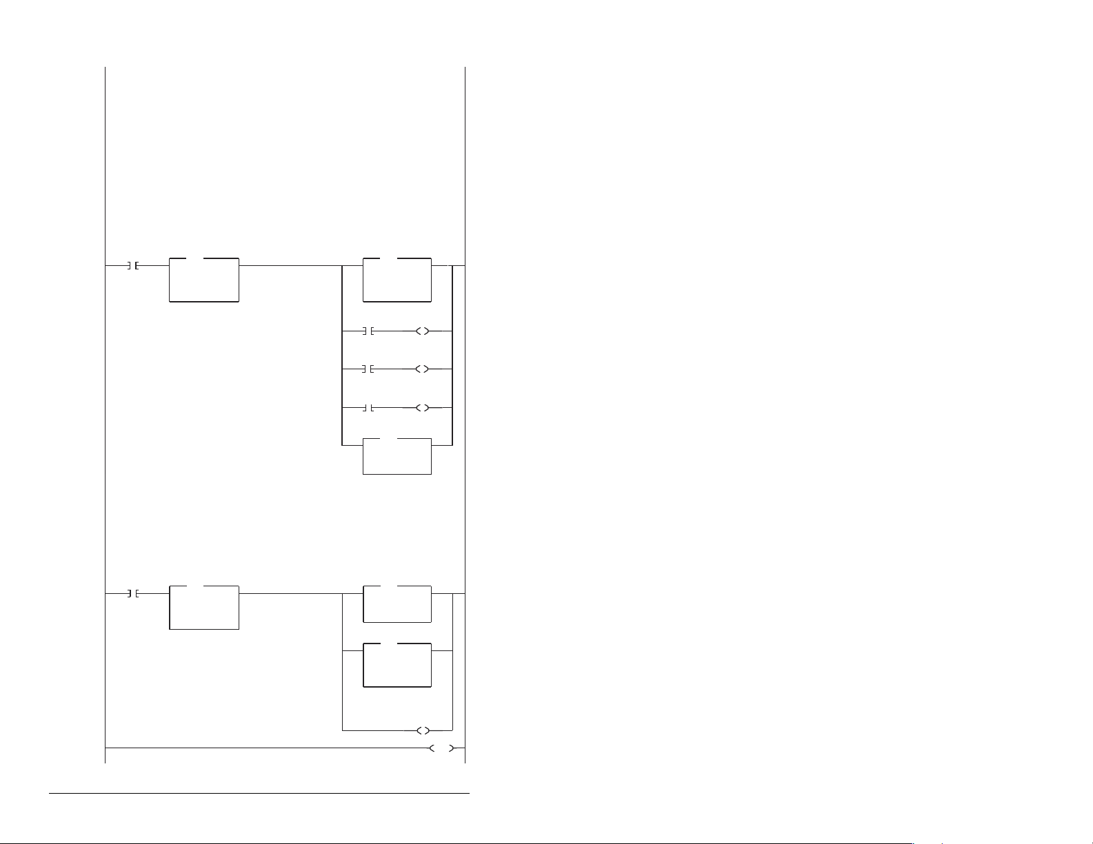
This circuit utilizes the Param eter Protocol. A REQUEST to Station 2 is processed only one at a time, and after each
RESPONSE from Station 2 a zero must be sent and received to 'handshake' before the next REQUEST/RESPONSE
transaction can take place. For example:
Send a parameter read request --> Receive a param. read response --> Send a "0"--> Receive a "0" --> [Transaction compl.]
If the RESPONSE PCA Word 1 (N10:8) is "0", then a REQUEST can be initiated.
Elsewhere in the user program these words must be loaded with messagedata prior to initiating the REQUEST.
N7:30 = RC = the operation to be performed("1" = Read, "2" = 16-bit Write)
N7:31 = PNU = the parameter number to read or write
N7:32
= SubIndex = the MDI port # ("0" = Host or MD65 drive, "5" = MDCOMM-PBUS, etc.)
N7:33 = PVA #1 (the parameter value (high word)) - only used when writing parameters
N7:34 = PVA #2 (the parameter value (low word)) - only used when writing parameters
The four Parameter Protocol Words set up in thescanner are used to perform the Parameter Protocol:
N20:8 = contains RC (the operation to be performed) and PNU (the parameter number to read or write) combined
N20:9 = Subindex (the MDIport #)
N20:10 = P
VA #1 (the parameter value
N20:11 = PVA #2 (the parameter value (low word))
B3:19/0 is turned ON elsewhere in the program after a REQUEST message (N7:30-34) is loaded. This causes one
Parameter Protocol read or write to occur and B3:19/0 is turned OFF when the transaction is complete.
Station 2
Par Prot
Messaging
Request
11
N10:8 is the Station 2 Response Parameter Access Word 1. It is <> 0 when a message has been received in response to a
message request. If the response is >= 7000 hex(28672 deci mal), then the adapter is responding that an error has occured.
In this case, the returned data in the response will contain a fault code and not the parameter value data.
The response message can be found at:
N7:40 = PCA Word = contains RCand PNU
N7:41
N7:42 = PVA #1 = the parametervalue (high word)
N7:43 = PVA #2 = the parameter value (low word)
The PVA's will either contain parameter read data, echo the parameter write data or contain an error code if unsuccessful.
Station 2
Par Prot
Messaging
Request
12
13
Station 2
RESPONSE
PCA Word
B3:19
0
= Subindex = the MDI port # ("0" = Host or MD65 Drive, "5" = MDCOMM-PBUS, etc.)
B3:19
0
Equal
Source A N10:8
Source B 0
Station 2
RESPONSE
PCA Word
Not Equal
Source A N10:8
Source B 0
EQU
EQU
NEQ
NEQ
(high word))
0<
0<
0<
0<
Station 2
PCA Word
MOV
MOV
Move
Source N7:31
Dest N20:8
PCA Word
RCb it 0
N7:30
0
RCb it 1
N7:30
1
RCb it 2
N7:30
2
IND Word
(Subindex)
RESPONSE Message
PCA Word
Station 2
PCA Word
RC bit 0
PCA Word
RCb it 1
PCA Word
RCb it 2
COP
COP
Copy File
Source #N7:32
Dest #N20:9
Length 3
COP
COP
Copy File
Source #N10:8
Dest #N7:40
Length 4
MOV
MOV
Move
Source 0
Dest N20:8
Station 2
Par Prot
Messaging
Request
N20:8
N20:8
N20:8
B3:19
77<
L
12
L
13
L
14
U
0
0<
0<
0<
END
D-6 PROFIBUS Communications Module
Page 93

D.2 Multi-Drive Example
D.2.1 Main Routine
This example program is for a PROFIBUS demonstration using a SLC5&05 processor with an SST Profibus scanner
(SST-PFB-SLC) in the first slot of the rack. The program is written for 3 drives with one Profibus adapter on the network
(MultiDrive Mode):
Station 0 MD65 with MDCOMM-PBUS
Station 1 MD65
Station 2 MD65
The expample program demonstrates using Logic Command / Reference, Logic Status / Feedback and Parameter
Access using the Parameter Protocol.
On power-up, zero out the transmitt buffer to the Scanner.
First Pass
S:1
0
15
Automatically have the SST-PFB-SCL scanner's watchdog period track that of the
SCL processor (recommended per SST user manual)
1
The Scanner is configured to 20 bytes (10 words) of inputs: 4 Bytes "Ctrl/Stat &Ref Fdbk" for each drive (= 12 Bytes)
Read the drives data from the Profibus scanner.
File N10: contains the acutal read data that can be used elsewhere in the ladder program.
Address Description
M1:1.0 (N10:0) Logic Status Drive 0
M1:1.1 (N10:1) Speed Feedback Drive 0
M1:1.2 (N10:2) Logic Status Drive 1
M1:1.3 (N10:3) Speed Feedback Drive 1
M1:1.4 (N10:4) Logic Status Drive 2
M1:1.5 (N10:5) Speed Feedback Drive 2
M1:1.6 (N10:6) Parameter Access Word 1 (PCA)
M1:1.7 (N10:7) Parameter Access Word 2 (IND)
M1:1.8 (N10:8) Parameter Access Word 3 (PVA 1)
M1:1.9 (N10:9) Parameter Access Word 4 (PVA 2)
2
Execute LAD 3 - Station 0 Drive Logic
3
Execute LAD 4 - Station 1 Drive Logic
4
Execute LAD 5 - Station 2 Drive Logic
Execute LAD 5 - Station 2 Drive Logic
5
5
Execute LAD 6 - Parameter Protocol
Execute LAD 6 - Parameter Protocol
6
6
Write the drives' data to the profibus scanner.
Write the drives' data to the profibus scanner.
File N20: contains the actual write data generated elsewhere in the ladder program.
File N20: contains the actual write data generated elsewherein the ladder program.
Station File No. Description
M0:1.0 (N20:0) Logic Command Drive 0
Station File No. Description
M0:1.1 (N20:1) Speed Reference Drive 0
M0:1.0 (N20:0) Logic Command Drive 0
M0:1.2 (N20:2) Logic Command Drive 1
M0:1.1 (N20:1) Speed Reference Drive 0
M0:1.3 (N20:3) Speed Reference Drive 1
M0:1.2 (N20:2) Logic Command Drive 1
M0:1.4 (N20:4) Logic Command Drive 2
M0:1.3 (N20:3) Speed Reference Drive 1
M0:1.5 (N20:5) Speed Reference Drive 2
M0:1.4 (N20:4) Logic Command Drive 2
M0:1.6 (N20:6) Parameter Access Word 1 ( PCA)
M0:1.7 (N20:7) Parameter Access Word 2 (IND)
M0:1.5 (N20:5) Speed Reference Drive 2
M0:1.8 (N20:8) Parameter Access Word 3 (PVA 1)
M0:1.6 (N20:6) Parameter Access Word 1 (PCA)
M0:1.9 (N20:9) Parameter Access Word 4 (PVA 2)
M0:1.7 (N20:7) Parameter Access Word 2 (IND)
M0:1.8 (N20:8) Parameter Access Word 3 (PVA 1)
7
M0:1.9 (N20:9) Parameter Access Word 4 (PVA 2)
7
8
8
8 Bytes "Parameter Access"
JSR
JSR
JumpTo Subroutine
SBR Fil e Num ber U:5
JSR
JSR
JumpTo Subroutine
SBR Fil e Num ber U:6
FLL
FLL
Fill File
Source 0
Dest #N20:0
Length 10
MOV
MOV
Move
Source S:3
2561<
Dest M0:1.4011
COP
COP
Copy File
Source #M1:1.0
Dest #N10:0
Length 10
JSR
JSR
Jump To Subroutine
SBR File Number U:3
JSR
JSR
Jump To Subroutine
SBR File Number U:4
JSR
JSR
Jump To Subroutine
SBR FileNumber U:5
JSR
JSR
Jump To Subroutine
SBR FileNumber U:6
COP
COP
CopyFile
Source #N20:0
COP
COP
Dest #M0:1.0
Copy File
Length 10
Source #N20:0
Dest #M0:1.0
Length 10
END
?<
END
SLC Ladder Logic Examples D-7
Page 94

D.2.2 Drive 0 Control/Reference Routine
Controlling the Logic Command word in the drive. B3:20/* bits are controlled elsewhere in the user program.
Station 0
Stop
Comman d
B3:20
0
0
Station 0
Start
Command
B3:20
1
1
Station 0
Jog
Command
B3:20
2
2
Station 0
Clear Faults
Command
B3:20
3
3
Station 0
Reverse
Command
B3:20
4
4
Station 0
Reverse
Command
B3:20
5
4
To control thespeed reference
need to have the values 11
6
7
"Never Closed"
B3:20
8
5
Station 0 Speed Reference
The MD65 parameter 38 (Speed Reference) needs to be set at 5 ("RS485 [MDI] Port").
N19:1 is controlled elsewhere in the user program.
9
10
over the Profibus the three reference select bits (bits 14-12)
Station 0
Speed Reference
Write
Station 0
Logic Comman d
STOP
N20:0
0
Station 0
Logic Comman d
START
N20:0
1
Station 0
Logic Comman d
JOG
N20:0
2
Station 0
Logic Comman d
CLEAR FAULTS
N20:0
3
Station 0
Logic Comman d
FORWARD
N20:0
4
Station 0
Logic Comman d
REVERSE
N20:0
5
Station 0
Logic Comman d
REFERENCE SELECT 0
N20:0
12
Station 0
Logic Comman d
REFERENCE SELECT 1
N20:0
13
Station 0
Logic Comman d
REFERENCE SELECT 2
N20:0
14
MOV
MOV
Move
Source N19:1
Dest N20:1
273<
273<
END
D-8 PROFIBUS Communications Module
Page 95

D.2.3 Drive 0-1 Control Reference Routine
gi oControlling the Lo c C mmand word in the drive. B3:21/* bits are controlled elsewhere in the user program.
Station 1
Stop
Command
B3:21
0
0
Station 1
Start
Command
B3:21
1
1
Station 1
Jog
Command
B3:21
2
2
Station 1
Clear Faults
Command
B3:21
3
3
Station 1
Reverse
Command
B3:21
4
4
Station 1
Reverse
Command
B3:21
5
4
To control the speed reference over the Profibus, the three Reference Select bits (bits 14-12) need to have the values 011.
6
7
"Never Closed"
B3:21
8
5
Station 1 Speed Reference
The MD65 parameter 38 (Speed Reference) needs to be set to 5 ("RS485 [MDI] Port").
N19:3 is controlled elsewhere in the user program.
9
10
Station 1
Speed Reference
Write
Station 1
Logic Command
STOP
N20:2
0
Station 1
Logic Co mmand
START
N20:2
1
Station 1
Logic Co mmand
JOG
N20:2
2
Station 1
Logic Co mmand
CLEAR FAULTS
N20:2
3
Station 1
Logic Co mmand
FORWARD
N20:2
4
Station 1
Logic Co mmand
REVERSE
N20:2
5
Station 1
Logic Co mmand
REFERENCE SELECT 0
N20:2
12
Station 1
Logic Co mmand
REFERENCE SELECT 1
N20:2
13
Station 1
Logic Co mmand
REFERENCE SELECT 2
N20:2
14
MOV
MOV
Move
Source N19:3
Dest N20:3
314<
0<
END
SLC Ladder Logic Examples D-9
Page 96

D.2.4 Drive 0-2 Control/Reference Routine
Controlling the Logic Command word in the drive. B3:22/* bits are controlled elsewhere in the user program.
Station 2
Stop
Command
B3:22
0
0
Station 2
Start
Command
B3:22
1
1
Station 2
Jog
Command
B3:22
2
2
Station 2
Clear Faults
Command
B3:22
3
3
Station 2
Reverse
Command
B3:22
4
4
Station 2
Reverse
Command
B3:22
5
4
To control the speed reference over the Profibus, the three Reference Select bits (bits 14-12) need to have the values 011.
6
7
"Never Closed"
B3:22
8
5
Station 2 Speed Reference
The MD65 parameter 38 - [Speed Reference]
needs to be set to 5 ("RS485 [MDI] ¨Port").
N19.5 is controlled elsewhere in the user program.
9
Station 2
Logic Comma nd
STOP
N20:4
Station 2
Logic Comma nd
START
N20:4
Station 2
Logic Comma nd
JOG
N20:4
Station 2
Logic Comma nd
CLEAR FAULTS
N20:4
Station 2
Logic Comma nd
FORWARD
N20:4
Station 2
Logic Comma nd
REVERSE
N20:4
Station 2
Logic Comma nd
REFERENCE SELECT 0
N20:4
12
Station 2
Logic Command
REFERENCE SELECT 1
N20:4
13
Station 2
Logic Comma nd
REFERENCE SELECT 2
N20:4
14
Station 2
Speed Reference
Write
MOV
MOV
Move
Source N19:5
Dest
N20:5
0
1
2
3
4
5
314<
0<
10
END
D-10 PROFIBUS Communications Module
Page 97
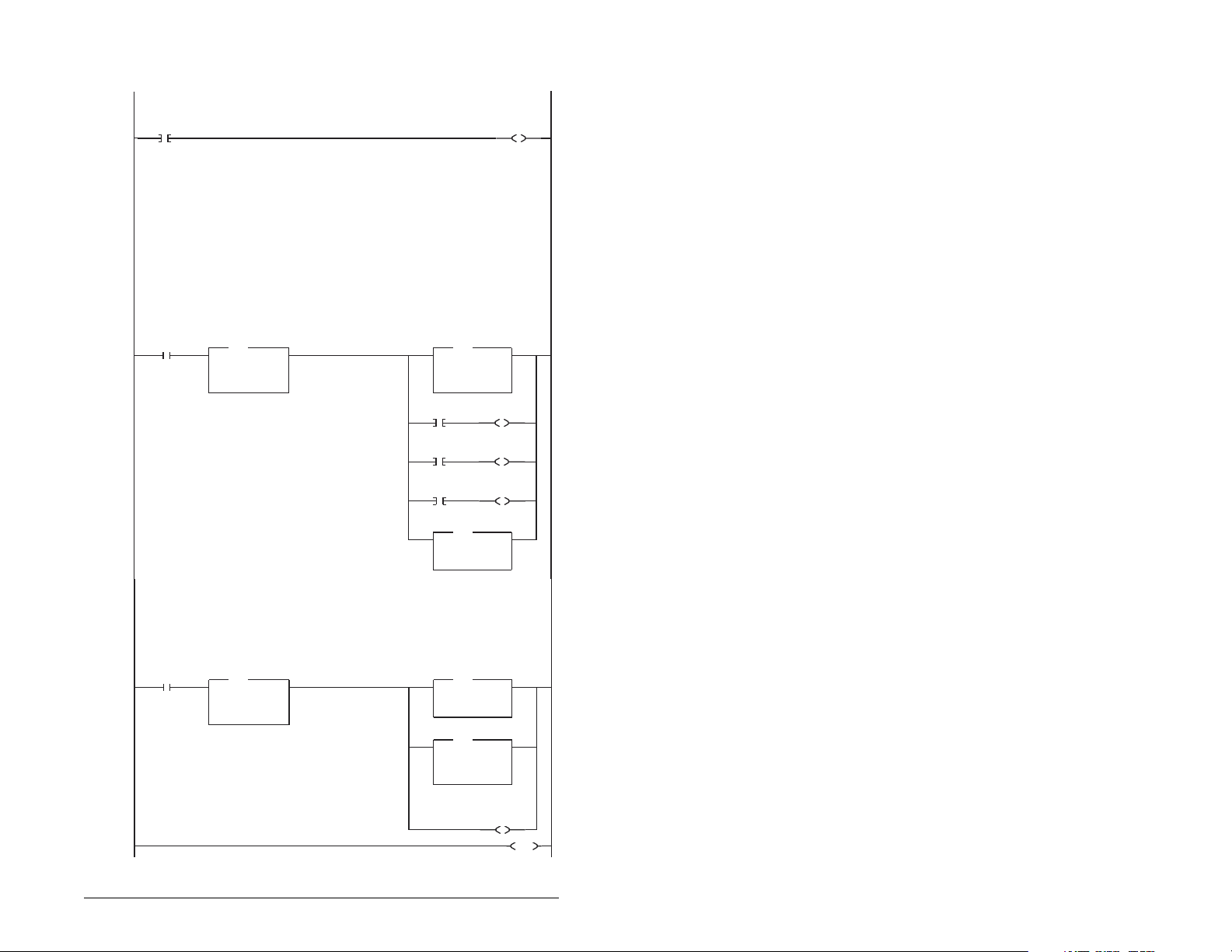
D.2.5 Parameter Accessing Routine
S:1
15
B3:19
B3:19
r
.
port #)
MDI
RESPONSE
PCA Word
EQU
EQU
0
0
Equa
Source A N10:6
Source B 0
RESPONSE
PCA Word
NEQ
NEQ
Not Equal
Source A N10:6
Source B 0
0<
0<
0<
0<
PCA Word
MOV
MOV
Move
Source N7:11
Dest N20:6
RC bit 0
N7:10
0
RC bit 1
N7:10
1
RC bit 2
N7:10
2
IND Word
(Subindex)
COP
COP
Copy File
Source #N7:12
Dest #N20:7
Length 3
RESPONSE Message
PCA Word
COP
COP
Copy File
Source #N10:6
Dest #N7:20
Length 4
PCA Word
MOV
MOV
Move
Source 0
Dest N20:6
Par Prot
Messaging
Request
77<
12304<
PCA Word
RC bit 0
N20:6
L
12
PCA Word
RC bit 1
N20:6
L
13
PCA Word
RC bit 2
N20:6
L
14
0<
12304<
Par Prot
Messaging
Request
B3:19
U
0
This section of the outine is only needed if the application needs to perform ParameterProtocol Reads or Writes to Station 2.
On power-up, initialize the Parameter Protocol routine.
First Pass
0
This circuit utilizes the Para meter Protocol. A REQUEST to the Profibus adapter is processed only one at a time,
and after each RESPONSE from the adapter a zero must be sent and received to 'handshake' before the next
REQUEST/RESPONSE transaction can take place. For example:
Send a parameter read request --> Receive a parameter read response --> Send a "0" --> Receivea "0" --> [Transaction complete]
If the RESPONSE PCA Word 1 (N10:6) is "0", then a REQUEST can be initiated
Elsewhere in the user program these words must be loaded with message data prior to initiating the REQUEST.
N7:10 = RC = the operation to be performed ("1"= Read, "2" = 16-bit Write)
N7:11 = PNU = the parameter number to read or write
N7:12 = Subindex = the MDIport # ("0" = Station 0, "1" = Station 1, "2" = Station 2, "5"= MDCOMM-PBUS, etc.)
N7:13 = PVA #1 (the parameter value (high word)) - only used when writing parameters
N7:14 = PVA #2 (the parameter value (low word)) - only used when writing parameters
The four Parameter Protocol Words set up in the scannerare used to perform the Parameter Protocol:
N20:6 = contains RC (the operation to be performed)and PNU (the parameter number to read or write) combined
N20:7 = Subindex (the
N20:8 = PVA #1 (the parameter value(high word))
N20:9 = PVA #2 (the parameter value(low word))
B3:19/0 is turned ON elsewhere in the program after a REQUEST message (N7:10-14) is loaded. This causes one
Parameter Protocol read or write to occur and B3:19/0 is turned OFF when the transaction is complete.
Par Prot
Messaging
Request
1
N10:6 is the Response Parameter Access Word 1. It is <> 0 when a message has been received in response to a
message request. If the response is >= 7000 hex(28672 decimal), then the adapter is responding that an error has occurred.
In this case, the returned data in the response will contain a fault code and not the parameter value data.
The response message can be found at:
N7:20 = PCA Word = contains RCand PNU
N7:21 = Subindex = the MDIport # ("0" = Station 0, "1" = Station 1, "2" = Station 2, "5"= MDCOMM-PBU S, etc.)
N7:22 = PVA #1 = the parametervalue (high word)
N7:23 = PVA #2 = the parametervalue (low word)
The PVA's will either contain parameter read data, echo the parameter write data or contain an error code if unsuccessful.
Par Prot
Messaging
Request
2
3
B3:19
U
0
END
SLC Ladder Logic Examples D-11
Page 98

D-12 PROFIBUS Communications Module
Page 99

GLOSSARY
communications module - Devices such as driv es, controllers,
and computers usually require a module to provide a
communication interface between them and a network such as
PROFIBUS. A module reads data on the network and transmits it to
the connected device. It also reads data in the device and transmits
it to the network.
The MDCOMM-PBUS PROFIBUS module is an module that
connects MD65 drives to a PROFIBUS network. Modules are
sometimes also called “adapters,” “card s,” “embedded
communication options,” “gateways,” and “peripherals.”
controller - Also called programmable logic controller. A solid-state
control system that has a user-programmable memory for storage
of instructions to implement specific functions such as I/O control,
logic, timing, counting, report generation, communication,
arithmetic, and data file manipulation. A controller consists of a
central processor, input/output interface , and memory. See also
scanner.
data rate - The data rate is the speed at which data is transferred
on the PROFIBUS network. The available data rates depend on the
type of cable and total cable length used on the network:
Baud Rate Maximum Cable Length
9.6 kpbs 1000 m
19.2 kpbs 1000 m
93.75 kpbs 1000 m
187.5 kpbs 1000 m
500 kpbs 400 m
1.5 Mbps 200 m
3 Mbps 100 m
6 Mbps 100 m
12 Mbps 100 m
MDI - Micro Drive Interface - A modification of the serial
communication protocol used by various Reliance Electric drives
and power products.
MDI peripheral - A device that provides an interface between MDI
and a network or user. Peripheral devices are also referred to as
“modules-.” The serial converter and MD65 OIM are examples of
MDI peripherals.
Glossary Glossary-1
Page 100

MDI product - A device that uses the MDI communications
interface to communicate with one or more peripheral devices. For
example, a motor drive such as a MD65 drive is a MDI product. In
this manual, a MDI product is also referred to as “product” or “host.”
Explicit Messaging - Explicit Messages are used to configure,
monitor, and diagnose devices over PROFIBUS.
fault action - Determines how the module and connected product
act when a communications fault (for example, a cable is
disconnected) occurs or when the scanner is switched out of run
mode. The former uses a communications fault action, and the latter
uses an idle fault action.
fault configuration - When communications are disrupted (for
example, a cable is disconnected), the module and MD65 drive can
respond with a user-defined fault configuration. The user sets the
data that is sent to the drive in the fault configuration parameters
parameters 13 (Flt Cfg Logic) through 22 (Flt Cfg D2). When a fault
action parameter is set to use the fault configuration and a fault
occurs, the data from these parameters is sent as the Command
Logic and/or Reference
faulted node recovery - This PROFIBUS feature lets you change
the configuration of a device that is faulted on the network. For
example, if a device is added to a network and it does not have a
unique address, it will fault. If you have a configuration tool that
supports faulted node recovery and your module is using
parameters to set its node address and data rate, you can change
the node address.
flash update - The process of updating firmware in the module.
The module can be flash updated using the X-Modem protocol and
a MDCOMM-232 serial converter.
GSD file - Used by the network configuration tool to identify the type
of module and its capabilities so that it can configure the module for
the network. This is usually supplied on floppy disk as a text tile.
hold last - When communications are disrupted (for example, a
cable is disconnected), the module and MD65 drive can respond by
holding last. Hold last results in the drive receiving the last data
received via the PROFIBUS connection before the disruption. If the
drive was running and using the reference from the module, it will
continue to run at the same reference.
I/O data - I/O data, sometimes called “implicit messages” or “input/
output,” transmit time-critical data such as a Logic Command and
Reference. The terms “input” and “output” are defined from the
scanner’s point of view. Output is transmitted by the scanner and
consumed by the module. Input is transmitted by the module and
consumed by the scanner.
Glossary-2 PROFIBUS Communications Module
 Loading...