

Page 1

MD60 AC Drive
User Manual
Version 3.0
Instruction Manual
D2-3499-3
Page 2
The information in this manual is subject to change without notice.
Trademarks not belonging to Rockwell Automation are property of their respective companies.
Throughout this manual, the following notes are used to alert you to safety
considerations:
ATTENTION:Identifies information about practices or
circumstances that can lead to personal injury or death,
!
Important: Identifies information that is critical for successful application and
!
MD60, VS Utilities, and Reliance are trademarks of Rockwell Automation.
property damage, or economic loss.
understanding of the product.
ATTENTION: Only qualified personnel familiar with the
construction and operation of this equipment and the hazards
involv ed should install, adjust, operate , or service this equipment.
Read and understand this document in its entirety before
proceeding. Failure to observ e this precaution could result in
severe bodily injury or loss of life.
ATTENTION: The drive contains high volt age capacitors that take
time to discharge after removal of mains supply. Before working
on the drive, ensure isolati on of mains supply from line i nputs [R,
S, T (L1, L2, L3)]. Wait three (3) minutes for capacitors to
discharge to safe v oltage lev els. Darkened displa y LEDs is not an
indication that capacitors ha ve discharged to safe voltage le v els .
Failure to observe thi s precaution could result in severe bodily
injury or loss of life.
ATTENTION: The drive can operate at and maintain z ero speed.
The user is responsible f or assuring safe c onditions fo r operating
personnel by providing suitab le guards , audib le or visual alarms,
or other devices to indicate that the drive is operating, or may
operate, at or near zero speed. Failu re to observe this precaution
could result in severe bodily injury or loss of li fe.
ATTENTION: The drive contains ESD- (Electrostatic Discharge)
sensitive parts and assemblies. Static control precautions are
required when installing, testing, servicing, or repairing the driv e.
Erratic machine operation and damage to, or destruction of,
equipment can result if this procedure is not f ollowed. Failure to
observe this precaution can result in bodily injury.
ATTENTION: The user must provide an external, hardwired
emergency stop circuit outside of the drive circu itry . This circuit ry
must disable the system in case of improper operation.
Uncontrolled machine operation ma y result if this procedure is not
followed. Failure to observe this p recaut ion could result in bo dily
injury.
ATTENTION: The user is responsible for conforming with all
applicable local and national code s. Failure to observe this
precaution could result in damage to, or destruction of, the
equipment.
ATTENTION: An incorrectly applied or installed drive can result
in component damage or reduction in product life. Wiring or
application errors, such as undersizing the motor, incorrect or
inadequate AC supply, or excessive ambient temper atures may
result in malfunction of the system.
©2003 Rockwell Automation. All rights reserved.
Page 3

Chapter 1 Introduction
1.1 Getting Assistance from Reliance Electric..................... 1-1
Chapter 2 About the MD60 Drive
2.1 Identifying the Drive by Model Number.......................... 2-1
2.2 MD60 Drive Ratings, Model Numbers, and Frame
Sizes .............................................................................2-2
2.3 Kits.................................................................................2-3
2.4 Storage Guidelines........................................................2-4
Chapter 3 Mounting the Drive
3.1 General Requirements for the Installation Site.............. 3-1
3.1.1 Operating Conditions........................................... 3-2
3.1.2 Recommended Mounting Clearances .................3-2
3.1.3 Mounting Dimensions for the MD60 Drive........... 3-3
3.2 Mounting the Drive......................................................... 3-4
3.2.1 Protecting the Drive from Debris......................... 3-4
Chapter 4 Grounding the Drive
4.1 RFI Filter Grounding...................................................... 4-2
Chapter 5 Installing Power Wiring
5.1 Opening the Cover......................................................... 5-1
5.2 Verifying Drive AC Input Ratings Match Available
Power...........................................................................5-2
5.2.1 Ungrounded Distribution Systems....................... 5-2
5.2.2 Input Power Conditioning .............. ... ................... 5-4
5.3 Power Wiring Specifications..........................................5-5
5.4 Power Terminal Block Connections ............................... 5-5
5.5 Fuses and Circuit Breakers ........................................... 5-6
5.6 Motor Cable Types Acceptable for 200-600 Volt
Installations ...................................................................5-8
5.7 Reflected Wave Protection............................................5-9
5.8 Output Disconnect.......................................................5-10
CONTENTS
Chapter 6 Installing Control Wiring
6.1 Stop Circuit Requirements.............................................6-1
6.1.1 Compliance with Machinery Safety Standard EN
60204-1:1992...................................................... 6-2
6.2 Motor Start/Stop Precautions......................................... 6-2
6.3 I/O Wiring Recommendations........................................ 6-3
6.3.1 Maximum Cable Length Recommendations........ 6-3
6.4 Wiring the Control Terminal Block................................. 6-4
6.4.1 I/O Wiring Examples............................................6-5
Contents I
Page 4

6.4.2 Typical Multiple Drive Connection Examples.......6-7
6.5 Start and Speed Reference Control...............................6-8
6.6 Accel/Decel Selection....................................................6-9
Chapter 7 Completing the Installation
7.1 Checking the Installation Before Applying Power to the
Drive ..............................................................................7-1
7.2 Powering Up After Installation is Complete....................7-2
Chapter 8 Using the Integral Keypad to Program and Control the Drive
8.1 Keypad Components .....................................................8-1
8.1.1 Display Description..............................................8-2
8.1.2 LED Descriptions.................................................8-2
8.1.3 Key Descriptions..................................................8-3
8.2 About Parameters................................ ... ... ....................8-4
8.3 How Parameters are Organized ........................... .........8-4
8.4 Viewing and Adjusting Basic (P) and Advanced (A)
Parameters....................................................................8-5
8.5 Viewing the Display (d) Parameters...............................8-6
Chapter 9 Parameter Descriptions
9.1 Basic Program Group Parameters.................................9-2
9.2 Advanced Group Parameters ........................................9-8
9.3 Display Group Parameters...........................................9-27
Chapter 10 Troubleshooting the Drive
10.1Fault Codes..................................................................10-1
10.1.1Manually Clearing Faults...................................10-2
10.1.2Automatically Clearing Faults (Auto Restart
Feature)............................................................10-2
10.2Troubleshooting Tables ................................................10-6
10.2.1Problem: Drive Does Not Start From Terminal Block
Start or Run Inputs ............................................10-6
10.2.2Problem: Drive Does Not Start From Integral
Keypad.............................................................10-7
10.2.3Problem: Drive Does Not Respond to Changes in
Speed Command ................................. .............10-7
10.2.4Problem: Motor and/or Drive Will Not Accelerate to
Commanded Speed ..........................................10-8
10.2.5Problem: Motor Operation is Unstable...............10-8
10.2.6Problem: Drive Will Not Reverse Motor
Direction...........................................................10-9
Appendix A Technical Specifications................................................... A-1
Appendix B Record of User Settings ...................................................B-1
Appendix C Parameters Cross-Referenced by Name ......................... C-1
II MD60 AC Drive User Manual
Page 5

Appendix D CE Conformance Requirements .......................................D-1
Appendix E Accessories.......................................................................E-1
Appendix F RS485 (MDI) Protocol........................................... .............F-1
Appendix G RJ45 Splitter Cable.......................................................... G-1
Index ......................................................................................Index-1
Contents III
Page 6

IV MD60 AC Drive User Manual
Page 7

List of Figures
Figure 2.1 – Identifying the Drive by Model Number..................................2-1
Figure 3.1 – Minimum Mounting Clearances.............................................3-2
Figure 3.2 – Drive Dimensions - Front View..............................................3-3
Figure 3.3 – Drive Dimensions - Bottom View...........................................3-3
Figure 4.1 – Typical Grounding..................................................................4-1
Figure 5.1 – Opening the Cover.................................................................5-1
Figure 5.2 – Removing the Finger Guard..................................................5-2
Figure 5.3 – Jumper Location (A Frame Shown).......................................5-3
Figure 5.4 – Phase-to-Ground MOV Removal...........................................5-3
Figure 5.5 – Power Terminal Block Connections.......................................5-5
Figure 6.1 – Wiring the Control Terminal Block.........................................6-4
Figure 6.2 – I/O Wiring Examples..............................................................6-5
Figure 6.3 – Override Priority for the Speed Reference Command........... 6-8
Figure 6.4 – Accel/Decel Selection............................................................6-9
Figure 8.1 – Integral Keypad .....................................................................8-1
Figure 9.1 – Accel Time 1 (P039)..............................................................9-7
Figure 9.2 – Decel Time 1 (P040)..............................................................9-7
Figure 9.3 – Accel Time 2 (A067)............................................................9-11
Figure 9.4 – Decel Time 2 (A068)............................................................9-12
Figure 9.5 – DC Brake Level (A081)........................................................9-14
Figure 9.6 – S Curve% (A083) Examples................................................9-15
Figure 9.7 – Start Boost (A084)...............................................................9-16
Figure 9.8 – Motor OL Select (A090).......................................................9-17
Figure 9.9 – Derating Guidelines Based on PWM Frequency (A091)
Selection...........................................................................9-18
Figure 9.10 – Drive Status (d006) Bit Definitions..................................... 9-28
Figure 9.11 – Control Source (d012) Bit Definitions ................................9-29
Figure 9.12 – Control Input Status (d013) Bit Definitions.........................9-30
Figure 9.13 – Digital Input Status (d014) Bit Definitions..........................9-30
Figure 9.14 – Comm Status (d015) Bit Definitions...................................9-31
Contents V
Page 8

VI MD60 AC Drive User Manual
Page 9

List of Tables
Table 2.1 – Drive Ratings, Model Numbers, and Frame Sizes.................. 2-2
Table 2.2 – Standard Kits..........................................................................2-3
Table 3.1 – Ambient Operating Temperatures and Mounting Clearances. 3-2
Table 3.2 – Mounting Specifications..........................................................3-4
Table 5.1 – Corrective Actions for Input Power Conditions.......................5-4
Table 5.2 – Power Wiring Specifications...................................................5-5
Table 5.3 – Power Terminal Block Specifications......................................5-5
Table 5.4 – Drive, Fuse, and Circuit Breaker Ratings................................5-7
Table 5.5 – Shielded Motor Cable Types Acceptable for 200-600 Volt
Installations..........................................................................5-8
Table 5.6 – Maximum Cable Length Recommendation.............................5-9
Table 6.1 – Recommended Control and Signal Wire................................. 6-3
Table 6.2 – I/O Terminal Block Specifications...........................................6-3
Table 6.3 – Typical Multiple Drive Connection Examples..........................6-7
Table 8.1 – LED Descriptions....................................................................8-2
Table 8.2 – Key Descriptions.....................................................................8-3
Table 8.3 – Viewing and Adjusting Basic (P) and Advanced (A)
Parameters..........................................................................8-5
Table 8.4 – Viewing the Display (d) Parameters........................................8-6
Table 9.1 – Trip Points for Digital Output Relay.......................................9-11
Table 9.2 – Selecting the Reference Source Using Presets....................9-13
Table 10.1 – Fault Descriptions and Corrective Actions..........................10-3
Table 10.2 – Problem: Drive Does Not Start From Terminal Block Start
or Run Inputs ...................................................................10-6
Table 10.3 – Problem: Drive Does Not Start From Integral Keypad........ 10-7
Table 10.4 – Problem: Drive Does Not Respond to Changes in Speed
Command.........................................................................10-7
Table 10.5 – Problem: Motor and/or Drive Will Not Accelerate to
Commanded Speed.......................................................... 10-8
Table 10.6 – Problem: Motor Operation is Unstable................................10-8
Table 10.7 – Problem: Drive Will Not Reverse Motor Direction...............10-9
Contents VII
Page 10

VIII MD60 AC Drive User Manual
Page 11

CHAPTER 1
Introduction
This manual is intended for qualified electrical personnel familiar
with installing, programming, and maintaining AC drives.
This manual contains information on:
• Installing and wiring the MD60 drive
• Programming the drive
• Troubleshooting the drive
The latest version of this manual is available from
http://www.theautomationbookstore.com or
http://www.reliance.com/docs_onl/online_stdrv.htm.
1.1 Getting Assistance from Reliance
Electric
If you have any questions or problems with the products described
in this instruction manual, contact your local Reliance Electric sales
office.
For technical assistance, call 1-800-726-8112. Before calling,
please review the troubleshooting section of this manual and check
the Reliance Standard Drives website for additional information.
When you call this number, you will be asked for the drive model
number or catalog number and this instruction manual number.
Introduction 1-1
Page 12

1-2 MD60 AC Drive User Manual
Page 13

CHAPTER 2
About the MD60 Drive
This chapter provides information about the MD60 AC drive,
including:
• How to identify the drive
• Descriptions of NEMA ratings
2.1 Identifying the Drive by Model
Number
Each drive can be identified by its model number, as shown in
figure 2.1. The model number is on the shipping label and the drive
nameplate. The model number includes the drive and any options.
Drive model numbers are provided in table 2.1.
6MD V N - 1P5 1 1 1
6MD = MD60 Drive
A = 1-Phase, 240 VAC
V = 1-Phase, 120 VAC
B = 3-Phase, 240 VAC
D = 3-Phase, 460VAC
N = IP20 (Open)
@115V / 230 VAC
1P5 = 1.5 A, 0.25 HP
2P3 = 2.3 A, 0.5 HP
4P5 = 4.5 A, 1 HP
6P0 = 6.0 A, 1.5 HP
8P0 = 8 A, 2 HP
012 = 12 A, 3 HP
017 = 17.5 A, 5 HP
@460 VAC
1P4 = 1.4 A, 0.5 HP
2P3 = 2.3 A, 1 HP
4P0 = 4 A, 2 HP
6P0 = 6 A, 3 HP
8P7 = 8.7 A, 5 HP
Reserved
0 = Not Filtered
1 = Internal Filter
Reserved
Figure 2.1 – Identifying the Drive by Model Number
About the MD60 Drive 2-1
Page 14

2.2 MD60 Drive Ratings, Model Numbers,
and Frame Sizes
Similar MD60 drive sizes are grouped into frame sizes to simplify
re-ordering and dimensioning. Refer to figure 3.2 for the dimensions
of each frame size.
Table 2.1 provides MD60 drive ratings, model numbers, and frame
sizes.
Table 2.1 – Drive Ratings, Model Numbers, and Frame Sizes
Drive Ratings
Frame
SizeInput Voltage kW HP
115V, 50/60 Hz
1-Phase
230V, 50/60 Hz
1-Phase
With Integral
EMC Filter
230V, 50/60 Hz
1-Phase
No Filter
230V, 50/60 Hz
3-Phase
460V, 50/60 Hz
3-Phase
Output
Current
0.2 0.25 1.5A 6MDVN-1P5101 A
0.37 0.5 2.3A 6MDVN-2P3101 A
0.75 1.0 4.5A 6MDVN-4P5101 B
1.1 1.5 6.0A 6MDVN-6P0101 B
0.2 0.25 1.5A 6MDAN-1P5111 A
0.37 0.5 2.3A 6MDAN-2P3111 A
0.75 1.0 4.5A 6MDAN-4P5111 A
1.5 2.0 8.0A 6MDAN-8P0111 B
0.2 0.25 1.5A 6MDAN-1P5101 A
0.37 0.5 2.3A 6MDAN-2P3101 A
0.75 1.0 4.5A 6MDAN-4P5101 A
1.5 2.0 8.0A 6MDAN-8P0101 B
0.2 0.25 1.5A 6MDBN-1P5101 A
0.37 0.5 2.3A 6MDBN-2P3101 A
0.75 1.0 4.5A 6MDBN-4P5101 A
1.5 2.0 8.0A 6MDBN-8P0101 A
2.2 3.0 12.0A 6MDBN-012101 B
3.7 5.0 17.5 6MDBN-017101 B
0.37 0.5 1.4A 6MDDN-1P4101 A
0.75 1.0 2.3A 6MDDN-2P3101 A
1.5 2.0 4.0A 6MDDN-4P0101 A
2.2 3.0 6.0A 6MDDN-6P0101 B
3.7 5.0 8.7A 6MDDN-8P7101 B
Model Number
2-2 MD60 AC Drive User Manual
Page 15

2.3 Kits
Table 2.2 lists kits for the MD60 drive. Contact Reliance Electric for
more information about these kits.
MD60 Serial Converter and cables MDCOMM-232
VS Utilities Software CD RECOMM-VSUTIL
MD60 Serial Converter (includes VS
Utilities Software)
NEMA 1/IP30 Kit (contains conduit box and
converter cover)
Remote LCD OIM Nema 4x/12 (includes
2.9 meter cable)
Remote Handheld OIM (Copy Cat Ke ypad;
includes 1.0 meter cable)
Bezel Kit (panel mount for Remote
Handheld OIM)
OIM Cable (1.0 meter OIM-to-RJ45 cable) MDCBL-CC1
OIM Cable (2.9 meter OIM-to-RJ45 cable) MDCBL-CC3
RJ45 Cable (2.0 meter RJ45-to-RJ45
cable, male-to-male connectors)
Serial Cable (2.0 meter serial cable with a
locking low profile connector to connect to
the serial converter and a 9-pin subminiature D female connector to connect to
a computer)
RJ45 Splitter Cables See Appendix G
Terminating Resistors (RJ45 120 Ohm
resistors; 2 pieces)
Terminal Block (RJ45 two-position terminal
block; 5 pieces)
Communications Option Kits See Appendix E
Dynamic Brake Resistors
EMI Filters
1
See Appendix E for more information.
Table 2.2 – Standard Kits
Kit Description Model Number
MDCOMM-VSU232
6MD-NM1A
6MD-NM1B
MD4ALCD
MD1CC
1
1
MDBZL-N1
MDCBL-RJ45
RECBL-SFC
AK-UO-RJ45-TRI
AK-UO-TB2P
AK-R2-xxx
6MDF-xxx
1
1
About the MD60 Drive 2-3
Page 16

2.4 Storage Guidelines
If you need to store the drive, follow these recommendations to
prolong drive life and performance:
• Store the drive within an ambient temperature range of -40° to
+85° C.
• Store the drive within a relative humidity range of 0% to 95%,
non-condensing.
• Do not expose the drive to a corrosive atmosphere.
2-4 MD60 AC Drive User Manual
Page 17

CHAPTER 3
Mounting the Drive
This chapter provides information that must be considered when
planning an MD60 drive installation and provides drive mounting
information and installation site requirements.
ATTENTION: Only qualified electrical personnel familiar with
the construction and operation of this equipment and the
!
hazards involved should install, adjust, operate, or service this
equipment. Read and understand this manual and other
applicable manuals in their entirety before proceeding. Failure
to observe this precaution could result in severe bodily injury
or loss of life.
ATTENTION: Use of power correction capacitors on the
output of the drive can result in erratic operation of the motor,
nuisance tripping, and/or permanent damage to the drive.
Remove pow er correc tion capacitors before proceeding.
Failure to observe this precaution could result in damage to,
or destruction of, the equipment.
ATTENTION: The user is responsible f or conforming with all
applicable local, national, and international codes. Failure to
observe this precaution could result in damage to, or
destruction of, the equipment.
3.1 General Requirements for the
Installation Site
It is important to properly plan before installing an MD60 drive to
ensure that the drive’s environment and operating conditions are
satisfactory.
The area behind the drive must be kept clear of all control and
power wiring. Pow er connections may create electromagnetic fields
that may interfere with control wiring or components when run in
close proximity to the drive.
Read the recommendations in the following sections before
continuing with the drive installation.
Mounting the Drive 3-1
Page 18

3.1.1 Operating Conditions
Before deciding on an installation site, consider the following
guidelines:
• Protect the cooling fan by avoiding dust or metallic particles.
• Do not expose the drive to a corrosive atmosphere.
• Protect the drive from moisture and direct sunlight.
• Verify that the dr ive location will meet the environmental
conditions specified in table 3.1.
Table 3.1 – Ambient Operating Temperatures and Mounting Clearances
Ambient
Temperature
-10°C
(14°F)
40°C
(104°F)
50°C
(122°F)
1
Rating requires installation of the MD60 NEMA 1/IP30 Kit.
Enclosure
Rating
IP 20/Open Type Use Mounting Option A
IP 30/NEMA 1/
UL Type 1
IP 20/Open Type Use Mounting Option B
Minimum Mounting
ClearancesMinimum Maximum
(figure 3.1)
Use Mounting Option B
1
(figure 3.1)
(figure 3.1)
3.1.2 Recommended Mounting Clearances
Refer to figure 3.1 for the minimum mounting clearances. Refer to
section 3.1.3 for drive mounting dimensions.
25 mm
(1.0 in)
120 mm
(4.7 in)
Mounting Option A
No clearance required
between drives
Mounting Option B
120 mm
(4.7 in)
See figure 3.2 for drive dimensions.
Figure 3.1 – Minimum Mounting Clearances
3-2 MD60 AC Drive User Manual
120 mm
(4.7 in)
120 mm
(4.7 in)
Page 19
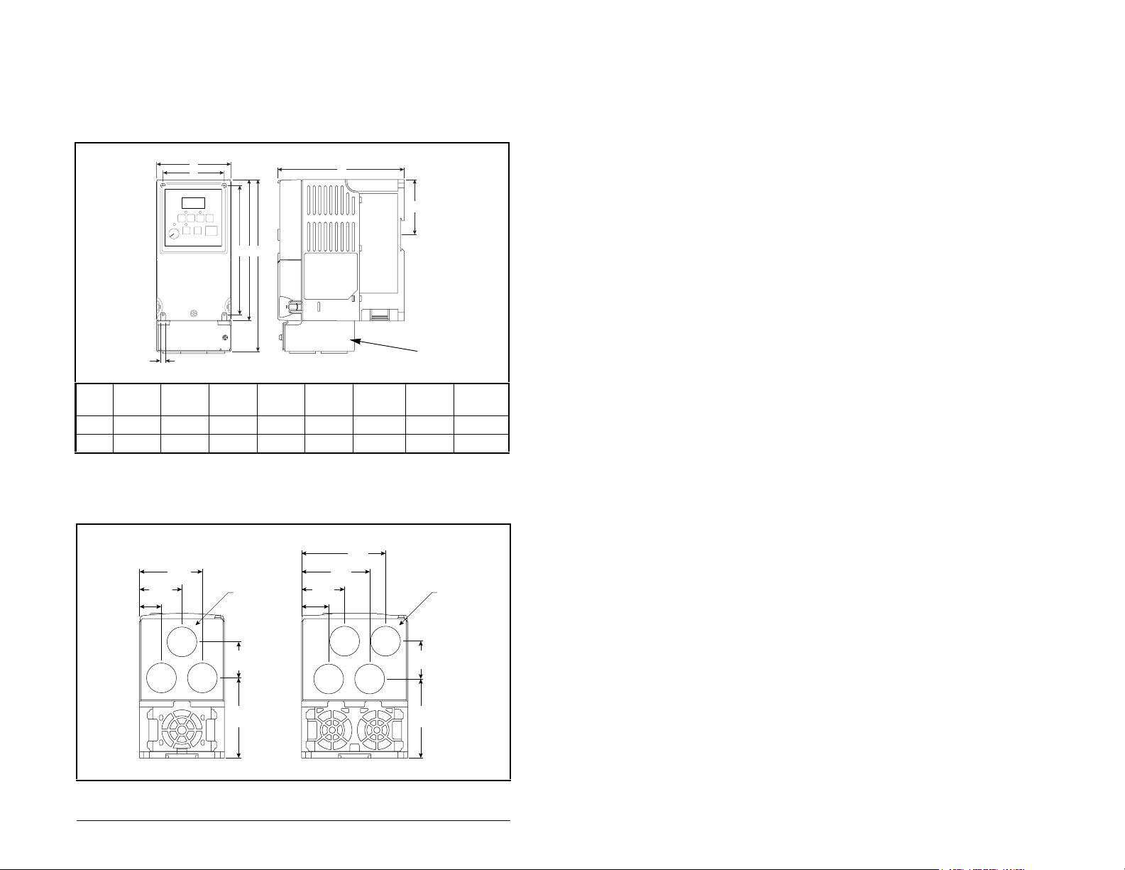
3.1.3 Mounting Dimensions for the MD60 Drive
F
Overall dimensions and weights are illustrated in figures 3.2 and 3.3
as an aid to calculating the total area required by the MD60 drive.
Dimensions are in millimeters and (inches). Weights are in
kilograms and (pounds). See table 2.1 for drive ratings by frame.
Frame A B
A
D
5.5 (0.22)
Front
1
B
GE
CDE2FG
Side
C
NEMA 1/IP30
Kit
A 80 (3.15) 185 (7.28) 136 (5.35) 67 (2.64) 152 (5.98) 59.3 (2.33) 140 (5.51) 1.4 (3.1)
B 100 (3.94) 213 (8.39) 136 (5.35) 87 (3.43) 180 (7.09) 87.4 (3.44) 168 (6.61) 2.2 (4.9)
Figure 3.2 – Drive Dimensions - Front View
1
Height dimension includes NEMA 1/IP30 Kit; see figure 3.3.
2
Height dimension without NEMA 1/IP30 Kit.
79.1
40.6
(1.60)
64.1
(2.52)
(3.11)
∅ 22.2
(0.88)
20.7
(0.81)
40.0
(1.57)
59.2
(2.33)
∅ 22.2
(0.88)
25.6
(1.01)
Shipping
Weight
34.0
(1.34)
75.3
(2.96)
35.6
(1.40)
74.3
(2.93)
Frame A Frame B
Figure 3.3 – Drive Dimensions - Bottom View
Mounting the Drive 3-3
Page 20

3.2 Mounting the Drive
Mount the drive upright on a flat, vertical, and level surface.
• Install on 35 mm DIN rail
or
• Install with screws (see table 3.2).
Table 3.2 – Mounting Specifications
Minimum Panel
Thickness Screw Size Mounting Torque
1.9 mm (0.0747 in) M4 (#8-32) 1.56-1.96 N-m (14-17 in-lb)
3.2.1 Protecting the Drive from Debris
A plastic top panel is included with the drive. Install the panel to
prevent debris from falling through the vents of the drive housing
during installation. Remove the panel for IP 20/Open Type
applications.
3-4 MD60 AC Drive User Manual
Page 21
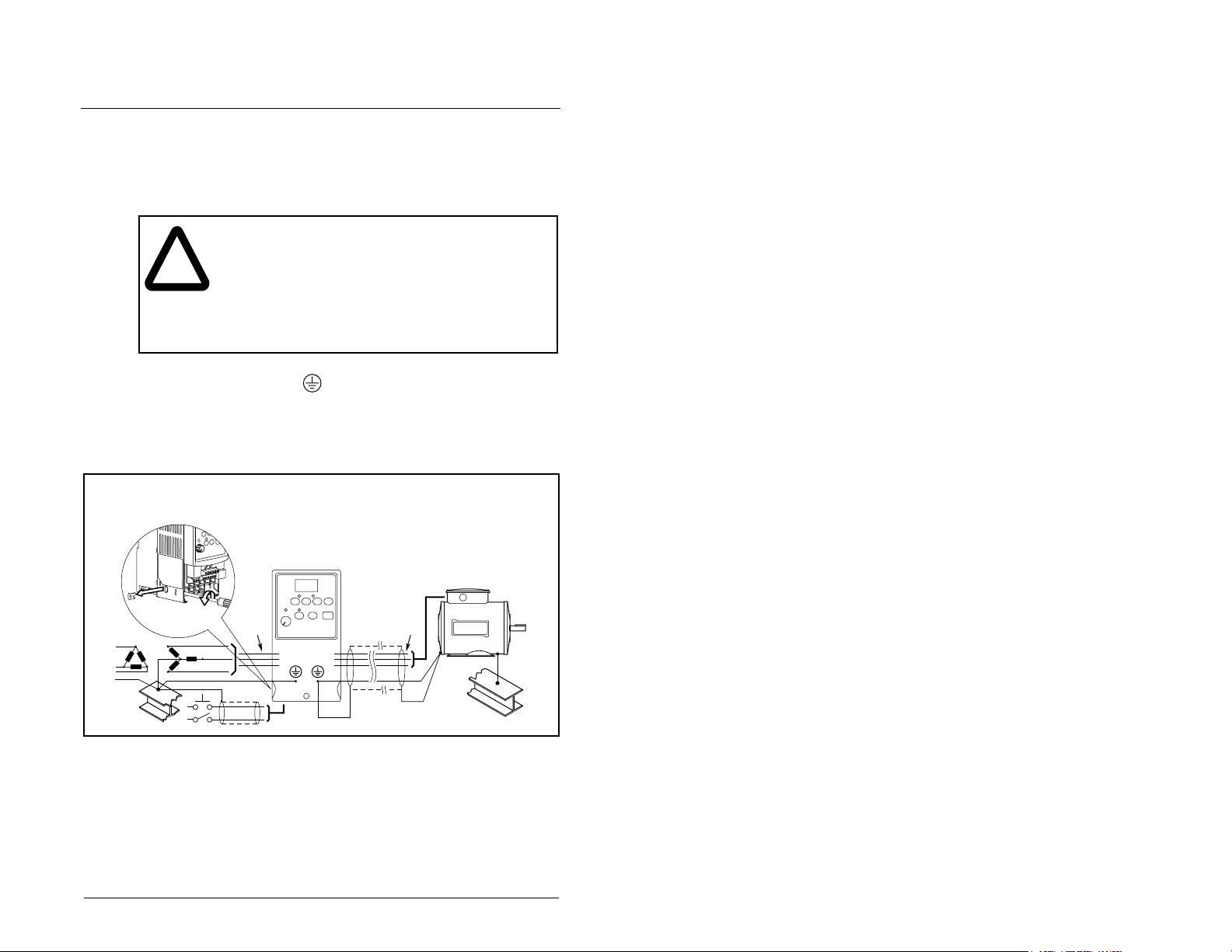
CHAPTER 4
Grounding the Drive
ATTENTION: The following information is merely a
guide for proper installation. Rockwell Automation
!
The drive Safety Ground - must be connected to system
ground. Ground impedance must conform to the requirements of
national and local industrial safety regulations and/or electrical
codes. The integrity of all ground connections should be periodically
checked.
cannot assume responsibility for the compliance or
the noncompliance to any code, national, local or
otherwise for the proper installation of this drive or
associated equipment. A hazard of personal injury
and/or equipment damage exists if codes are
ignored during installation.
Important:
is installed on an ungrounded system.
Tighten screw after jumper removal.
Jumper
Location
For installations within a cabinet, a single safety ground point or
ground bus bar connected directly to building steel should be used.
All circuits including the AC input ground conductor should be
grounded independently and directly to this point/bar.
Grounding the Drive 4-1
R/L1
S/L2
T/L3
Figure 4.1 – Typical Groun ding
Remove the MOV-to-ground jumper if the drive
U/T1
V/T2
W/T3
SHLD
Page 22

Ground Fault Monitoring
If a system ground fault monitor is to be used, only Type B
(adjustable) devices should be used to avoid nuisance tripping.
Safety Ground - (PE)
This is the safety ground for the drive that is required by code. One
of these points must be connected to adjacent building steel (girder,
joist), a floor ground rod, or bus bar. Grounding points must comply
with national and local industrial safety regulations and/or electrical
codes.
Motor Ground
The motor ground must be connected to one of the ground
terminals on the drive.
Shield Termination - SHLD
Either of the safety ground terminals located on the power terminal
block provides a grounding point for the motor cable shield. The
motor cable shield connected to one of these terminals (drive end)
should also be connected to the motor frame (motor end). Use a
shield terminating or EMI clamp to connect the shield to the safety
ground terminal. The NEMA 1/IP30 Kit may be used with a cable
clamp for a grounding point for the cable shield.
When shielded cable is used for contr o l and signal wiring, the
shield should be grounded at the source end only, not at the drive
end.
4.1 RFI Filter Grounding
Using single-phase drives with integral filter, or an e xternal filter with
any drive rating, may result in relatively high ground leakage
currents. Therefore, the filter must only be used in installations
with grounded AC supply systems and be permanently
installed and solidly grounded (bonded) to the building power
distribution ground.
Ensure that the incoming supply neutral is solidly connected
(bonded) to the same building power distribution ground. Grounding
must not rely on flexible cables and should not include any form of
plug or socket that would permit inadvertent disconnection. Some
local codes may require redundant ground connections. The
integrity of all connections should be periodically checked.
4-2 MD60 AC Drive User Manual
Page 23
Installing Power Wiring
ATTENTION: The user is responsible f or conforming
with all applicable local and national codes. Failure
!
This chapter provides instructions on wiring output wiring to the
motor and installing AC input power wiring.
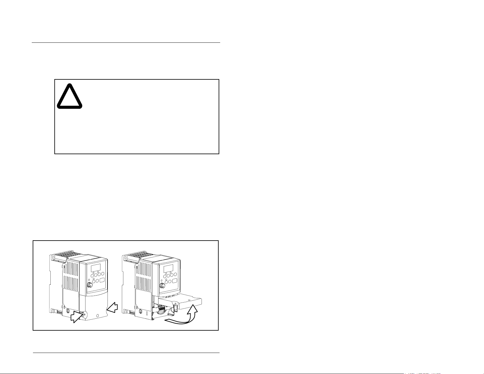
5.1 Opening the Cover
To access the power terminal block:
Step 1. Open the cover.
to observe this precaution could result in damage to,
or destruction of, the equipment.
ATTENTION: To avoid a possible shock hazard
caused by induced voltages, unused wires in the
conduit must be grounded at both ends. For the same
reason, if a drive sharing a conduit is being serviced
or installed, all drives using this conduit should be
disabled. This will help minimize the possible shock
hazard from “cross-coupled” power leads.
a. Press and hold in the tabs on each side of the cover.
b. Pull the cov er out and up to release (refer to figure 5.1).
CHAPTER 5
Figure 5.1 – Opening the Cover
Installing Power Wiring 5-1
Page 24
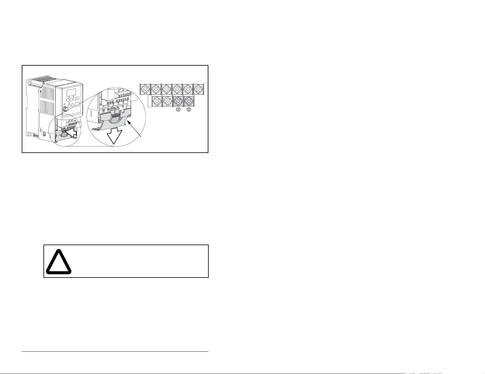
Step 2. Remove the finger guard (refer to figure 5.2).
a. Press in and hold the locking tab.
b. Slide finger guard down and out.
Replace the finger guard when wiring is complete.
BR-
BR+
Power Terminal
Block
Finger Guard
Figure 5.2 – Removing the Finger Guard
5.2 Verifying Drive AC Input Ratings
Match Available Power
It is important to verity that plant power meets the input power
requirements of the drive’s circuitry. Refer to table 5.4 for input
power rating specifications. Be sure input power to the drive
corresponds to the drive nameplate voltage and frequency.
V/T2T/L3S/L2R/L1 U/T1 W/T3
5.2.1 Ungrounded Distribution Systems
ATTENTION: MD60 driv es contain protective MO Vs
that are referenced to ground. These devices should
!
To prevent drive damage, the MOVs connected to ground should be
disconnected if the drive is installed on an ungrounded distribution
system where the line-to-ground voltages on any phase could
exceed 125% of the nominal line-to-line voltage.
5-2 MD60 AC Drive User Manual
be disconnected if the drive is installed on an
ungrounded distribution system.
Page 25
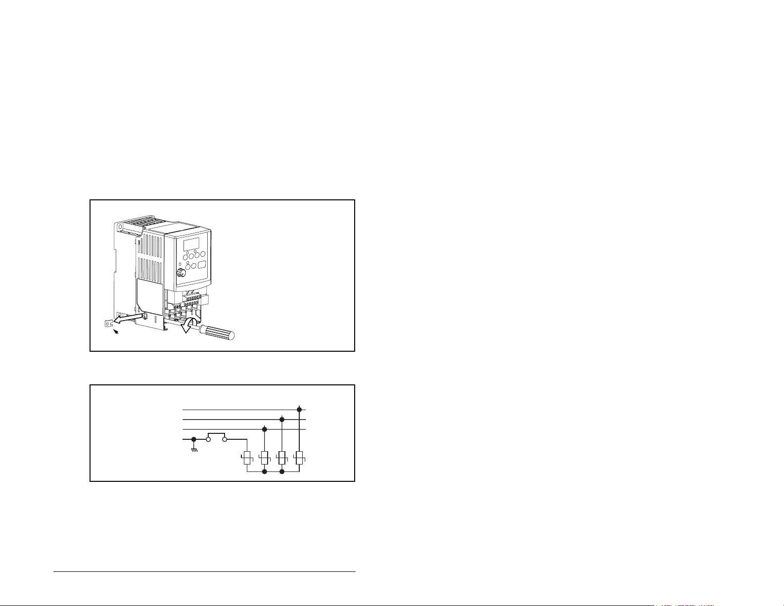
Disconnecting MOVs
To disconnect MOVs, you must remove the external jumper located
on the lower left side of the front of the drive.
To remove the jumper, use the following procedure and refer to
figures 5.3 and 5.4.
Step 1. Open the cover.
Step 2. Locate the screw below and to the left of the power
terminal block.
Step 3. Turn the screw counterclockwise to loosen.
Step 4. Pull the jumper completely out of the drive chassis.
Step 5. Tighten the screw to keep it in place.
Important: Tighten screw after
jumper removal.
Jumper
Figure 5.3 – Jumper Location (A Frame Shown)
Three-Phase
AC Input
Figure 5.4 – Phase-to-Ground MOV Removal
Installing Power Wiring 5-3
R/L1
S/L2
T/L3
Jumper
123
4
Page 26

5.2.2 Input Power Conditioning
The drive is suitable for direct connection to input power within the
rated voltage of the drive (see table 5.4). Table 5.1 lists certain input
power conditions that may cause component damage or reduction
in product life. If any of the conditions exist, install one of the
devices listed in the ”Corrective Action” column in table 5.1 on the
line side of the drive.
Important: Only one device per branch circuit is required. It
should be mounted closest to the branch and sized to
handle the total current of the branch circuit.
Table 5.1 – Corrective Actions for Input Power Conditions
Input Power Condition Corrective Action
Low line impedance (less than 1% line
reactance)
Greater than 120 kVA supply transformer
Line has power f ac to r correcti o n ca pa ci to rs
Line has frequent power interruptions
Line has intermittent noise spikes in excess of
6000V (lightning)
Phase-to-ground voltage exceeds 125% of
normal line-to-line voltage
Ungrounded distribution system
1
Contact Reliance Electric for application and ordering information.
• Install line reactor
or
• Install isolation
transformer
• Remove MOV jumper to
ground and install
isolation transformer
with grounded
secondary, if necessary.
1
5-4 MD60 AC Drive User Manual
Page 27
5.3 Power Wiring Specifications
Table 5.2 – Power Wiring Specifications
Power Wire Rating Recommended Copper Wire
Unshielded 600V, 75°C (167°F)
15 mils insulated, dry location
THHN/THWN
Shielded 600V, 90°C (194°F)
RHH/RHW-2
Shielded Tray rated 600V, 90°C (194°F)
RHH/RHW-2
Belden 29501-29507 or
equivalent
Shawflex 2ACD/3ACD or
equivalent
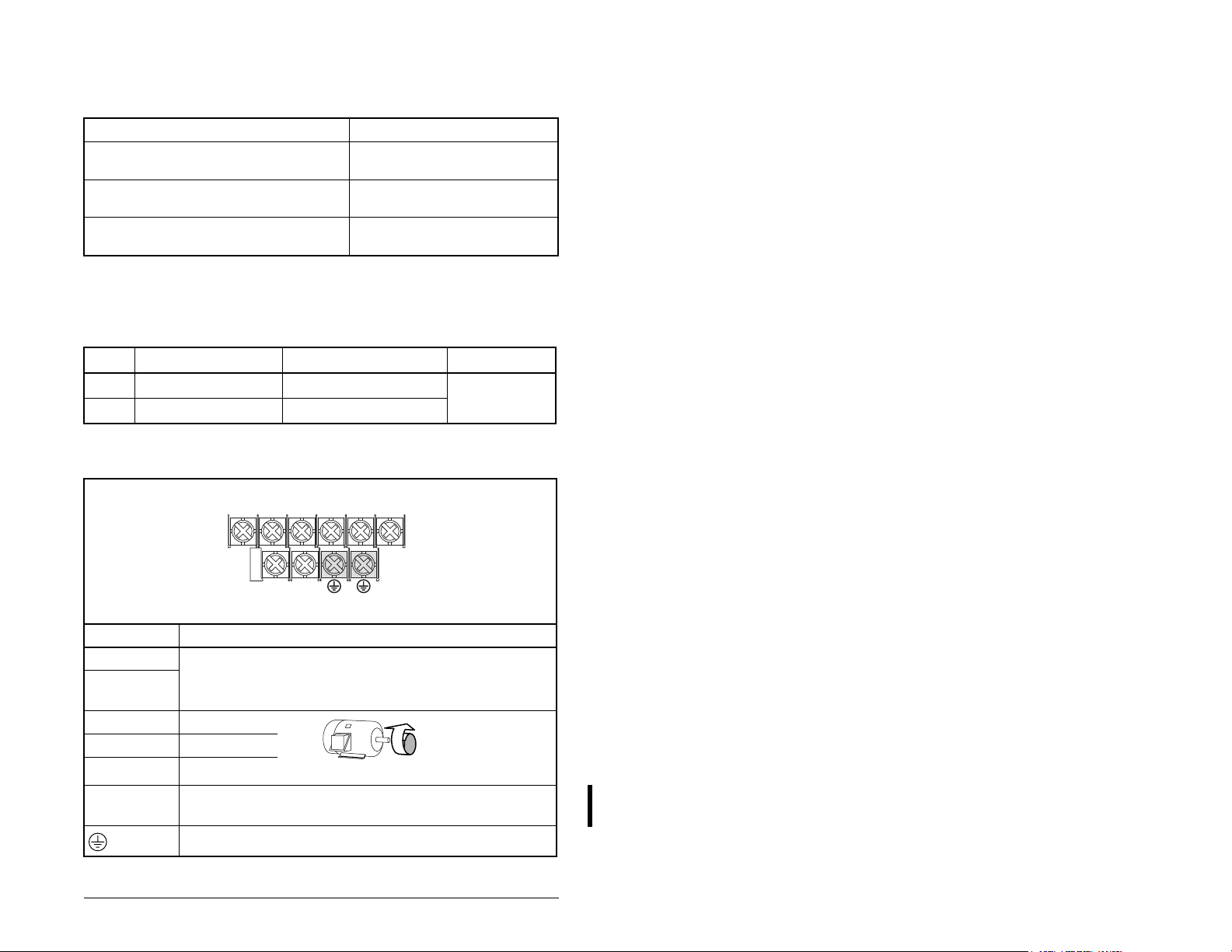
5.4 Power Terminal Block Connections
Table 5.3 – Power Terminal Block Specifications
Frame Maximum Wire Size
A
3.3 mm
B
5.3 mm
1
Maximum/minimum sizes that the terminal block will accept. These are not
recommendations.
2
(12 AWG) 0.8 mm2 (18 AWG)
2
(10 AWG) 1.3 mm2 (16 AWG)
1
Minimum Wire Size
BR+
BR-
V/T2T/L3S/L2R/L1 U/T1 W/T3
1
1.7-2.2 Nm
(16-19 in-lb)
Torque
Power Terminal Block
Terminal Description
R/L1, S/L2 1-Phase Input
R/L1, S/L2,
3-Phase Input
T/L3
U/T1 To Motor U/T1 Switch any two
V/T2 To Motor V/T2
W/T3 To Motor W/T3
motor leads to
change forward
direction.
BR+, BR- Dynamic Brake Resistor Connection
(All ratings 100% rated.)
PE Ground
Figure 5.5 – Power Terminal Block Connections
Installing Power Wiring 5-5
Page 28

5.5 Fuses and Circuit Breakers
The MD60 drive does not provide branch short circuit protection.
This product should be installed with either input fuses or an input
circuit breaker. National and local industrial safety regulations and/
or electrical codes may determine additional requirements for these
installations.
Table 5.4 provides drive ratings and recommended AC line input
fuse and circuit breaker information. Both types of short circuit
protection are acceptable for UL and IEC requirements. Sizes listed
are the recommended sizes based on 40 degree C and the U.S.
N.E.C. Other country, state or local codes may require different
ratings.
ATTENTION: To guard against personal injury and/
or equipment damage caused by improper fusing or
!
Fuses
The MD60 drive has been UL tested and approved for use with
input fuses. The ratings in table 5.4 are the minimum recommended
values for use with each drive rating. The devices listed in this table
are provided to serve as a guide.
circuit breaker selection, use only the recommended
line fuses/circuit breakers specified in table 5.4.
If fuses are chosen as the desired protection method, refer to
the recommended types listed below. If available amp ratings do not
match the tables provided, the closest fuse rating that exceeds the
drive rating should be chosen.
• IEC – BS88 (British Standard) Parts 1 & 2
2, type gG or equivalent should be used.
• UL Class CC, T or J must be used.
1
Typical designations include, but may not be limited to the following:
Parts 1 & 2: AC, AD, BC, BD, CD, DD, ED, EFS, EF, FF, FG, GF, GG, GH.
2
Typical designations include:
Type CC - KTK-R, FNQ-R
Type J - JKS, LPJ
Type T - JJS, JJN
1
, EN60269-1, Parts 1 &
2
5-6 MD60 AC Drive User Manual
Page 29
Circuit Breakers
The “other devices” listings in table 5.4 include both circuit breakers
(inverse time or instantaneous trip) and self-protecting motor
starters. If one of these is chosen as the desired protection
method, the following requirements apply.
• IEC and UL – Both types of devices are acceptable for IEC and
UL installations.
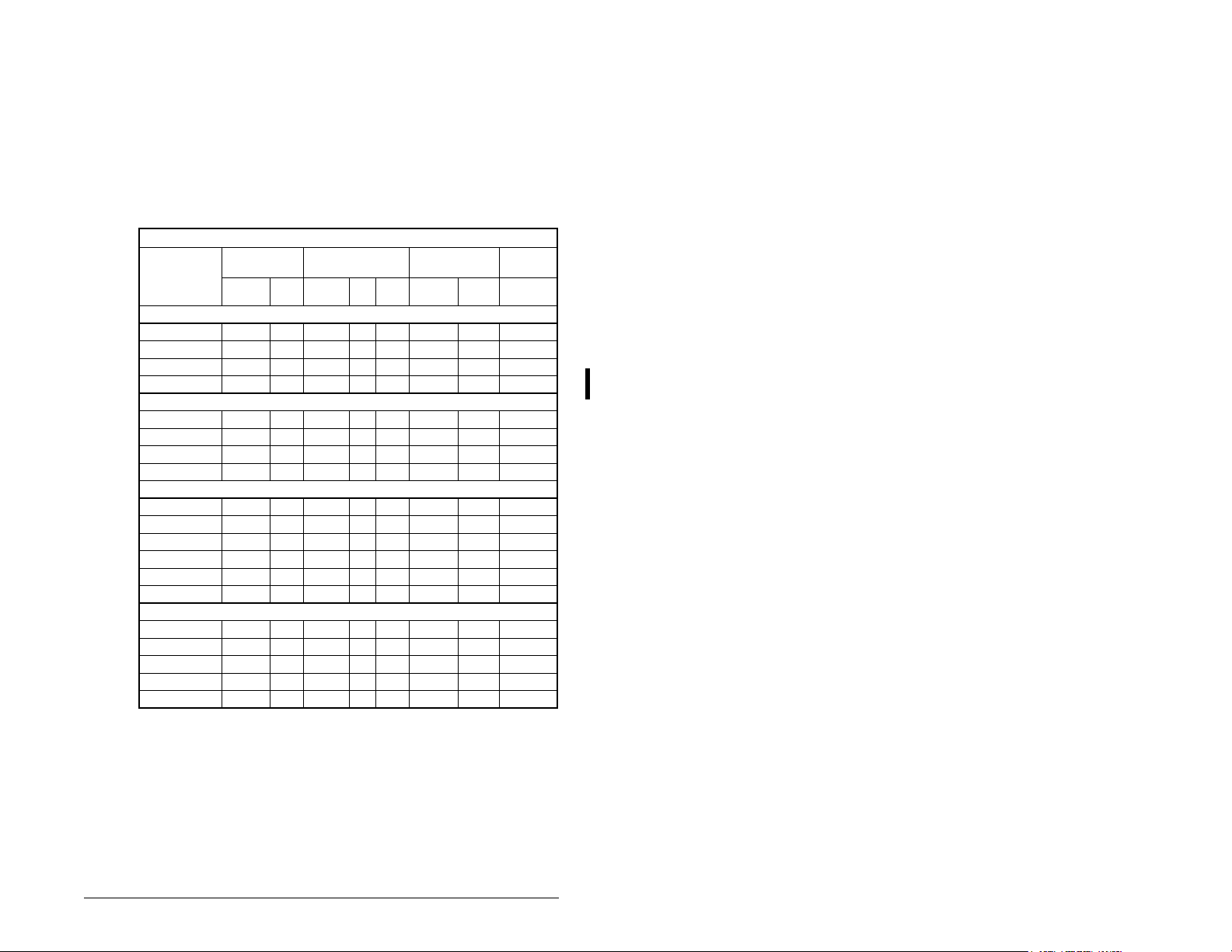
Table 5.4 – Drive, Fuse, and Circuit Breaker Ratings
Drive Ratings
Model Number
100 - 115V AC 1-Phase Input
6MDVN-1P5101 0.2 (0.25) 1.5 90-126 0.75 6.0 10 10 25
6MDVN-2P3101 0.37 (0.5) 2.3 90-126 1.15 9.0 15 15 30
6MDVN-4P5101 0.75 (1.0) 4.5 90-126 2.25 18.0 30 30 50
6MDVN-6P0101 1.1 (1.5) 6.0 90-126 3.0 24.0 40 40 70
200 - 240V AC 1-Phase Input; 0 - 230 V, 3-Phase Output
6MDAN-1P5111 0.2 (0.25) 1.5 180-265 0.75 5.0 10 5 25
6MDAN-2P3111 0.37 (0.5) 2.3 180-265 1.15 6.0 10 10 30
6MDAN-4P5111 0.75 (1.0) 4.5 180-265 2.25 10.0 15 15 50
6MDAN-8P0111 1.5 (2.0) 8.0 180-265 4.0 18.0 30 25 80
200 - 240V AC 3-Phase Input; 0 - 230 V, 3-Phase Output
6MDBN-1P5101 0.2 (0.25) 1.5 180-265 0.75 1.8 3 5 25
6MDBN-2P3101 0.37 (0.5) 2.3 180-265 1.15 2.5 6 5 30
6MDBN-4P5101 0.75 (1.0) 4.5 180-265 2.25 5.2 10 7 50
6MDBN-8P0101 1.5 (2.0) 8.0 180-265 4.0 9.5 15 15 80
6MDBN-012101 2.2 (3.0) 12.0 180-265 5.5 15.5 25 25 115
6MDBN-017101 3.7 (5.0) 17.5 180-265 8.6 21.0 35 30 165
380 - 480V AC 3-Phase Input; 0 - 480 V, 3-Phase Output
6MDDN-1P4101 0.37 (0.5) 1.4 340-528 1.4 1.8 3 3 30
6MDDN-2P3101 0.75 (1.0) 2.3 340-528 2.3 3.2 6 4 40
6MDDN-4P0101 1.5 (2.0) 4.0 340-528 4.0 5.7 10 7 60
6MDDN-6P0101 2.2 (3.0) 6.0 340-528 5.9 7.5 15 10 90
6MDDN-8P7101 3.7 (5.0) 8.7 340-528 8.6 9.0 15 15 145
Output Ratings Input Ratings
kW (HP) Amps
Voltage
Range kVA Amps
; 0 - 230 V, 3-Phase Output
Branch Circuit
Protection
Fuse
Other
Rating
Devices
Power
Dissipation
IP20 Open
Watts
Note: For carrier frequencies above 4 kHz, see figure 9.9.
Installing Power Wiring 5-7
Page 30

5.6 Motor Cable Types Acceptable for
200-600 Volt Installations
General
A variety of cable types are acceptable for drive installations. For
many installations, unshielded cable is adequate provided it can be
separated from sensitive circuits. As an approximate guide, allow a
spacing of 0.3 meters (1 foot) for every 10 meters (32.8 feet) of
length. In all cases, long parallel runs must be avoided. Do not use
cable with an insulation thickness less than 15 mils (0.4 mm/0.015
in). Do not route more than three sets of motor leads in a single
conduit to minimize “cross talk”. If more than three drive/motor
connections per conduit are required, shielded cable must be used.
• UL installations in 50°C ambient must use 600V, 75°C or 90°C
wire.
• For UL installations in 40°C ambient, 600V, 75°C or 90°C wire is
recommended.
• Use copper wire only. Wire gauge requirements and
recommendations are based on 75°
when using higher temperature wire.
Unshielded
THHN, THWN or similar wire is acceptable for drive installation in
dry environments provided adequate free air space and/or conduit
fill rates limits are provided. Do not use THHN or similarl y co at ed
wire in wet areas. Any wire chosen must have a minimum
insulation thickness of 15 mil and should not have large variations in
insulation concentricity.
C. Do not reduce wire gauge
Shielded
Refer to table 5.5 for acceptable shielded motor cable types.
.
Table 5.5 – Shielded Motor Cable Types Acceptable for 200-600 Volt Installations
Location Rating/Type Description
Standard
(Option 1)
600V, 75°C or 90°C
(167°F or 194°F)
RHH/RHW-2
Belden 2950129507 or equivalent
• Four tinned copper conductors with
XLPE insulation
• Foil shield and tinned copper drain
wire with 85% braid coverage
• PVC jacket
5-8 MD60 AC Drive User Manual
Page 31

Table 5.5 – Shielded Motor Cable Types Acceptable for 200-600 Volt Installations
Location Rating/Type Description
Standard
(Option 2)
Class I & II;
Division I & II
Tray rated 600V,
75°C or 90°C (167°F
or 194°F) RHH/
RHW-2
Shawflex 2ACD/
3ACD or equivalent
Tray rated 600V,
75°C or 90°C (167°F
or 194°F) RHH/
RHW-2
• Three tinned copper conductors with
XLPE insulation
• 5 mil single helical copper tape (25%
overlap min.) with three bare copper
grounds in contact with shield
• PVC jacket
• Three tinned copper conductors with
XLPE insulation
• 5 mil single helical copper tape (25%
overlap min.) with three bare copper
grounds in contact with shield
• PVC copper grounds on #10 AWG
and smaller
5.7 Reflected Wave Protection
The drive should be installed as close to the motor as possible.
Installations with long motor cables may require the addition of
external devices, such as reactors, to limit voltage reflections at the
motor (reflected wave phenomena). Contact Reliance Electric for
recommendations.
The reflected wave data applies to all frequencies 2 to16 kHz. For
240 V ratings, reflected wave effects do not need to be considered.
Table 5.6 – Maximum Cable Length Recommendation
Reflected Wave
380-480V Ratings Motor Insulation Rating Motor Cable Only
1000 Vp-p 15 meters (49 feet)
1200 Vp-p 40 meters (131 feet)
1600 Vp-p 170 meters (558 feet)
1
Longer cable lengths can be achieved by installing devices on the output of the drive.
Consult factory for recommendations.
Installing Power Wiring 5-9
1
Page 32

5.8 Output Disconnect
The drive is intended to be commanded by control input signals that
will start and stop the motor. A device that routinely disconnects
then reapplies output power to the motor for the purpose of starting
and stopping the motor should not be used. If it is necessary to
disconnect power to the motor while the drive is providing output
power, an auxiliary contact should be used to simultaneously
disable drive control run commands.
5-10 MD60 AC Drive User Manual
Page 33

CHAPTER 6
Installing Control Wiring
This chapter describes how to wire the signal and I/O terminal strip
for stop, speed feedback, and remote control signals.
To access the control terminal block, remove the drive cover (refer
to chapter 5).
Terminal block connections are detailed in figure 6.1.
6.1 Stop Circuit Requirements
ATTENTION: You must provide an external,
hardwired emergency stop circuit outside of the
!
Depending upon the requirements of the application, the MD60
drive can be configured to provide either a coast-to-rest or a rampto-rest operational stop without physical separation of the power
source from the motor. A coast-to-rest stop turns off the transistor
power device drivers. A ramp-to-rest stop fires the transistor power
device drivers until the motor comes to a stop, and then turns off the
power devices.
drive circuitry. This circuit must disable the system
in case of improper operation. Uncontrolled
machine operation can result if this procedure is not
followed. Failure to observe this precaution could
result in bodily injury.
In addition to the operational stop, you must provide a hardwired
emergency stop external to the drive. The emergency stop circuit
must contain only hardwired electromechanical components.
Operation of the emergency stop must not depend on electronic
logic (hardware or software) or on the communication of commands
over an electronic network or link.
Note that the hardwired emergency stop you install can be used at
any time to stop the drive.
Installing Control Wiring 6-1
Page 34

6.1.1 Compliance with Machinery Safety Standard
EN 60204-1:1992
This section applies to you if you must comply with machinery
safety standard EN 60204-1:1992, part 9.2.5.4, Emergency Stop.
The MD60 drive coast-to-rest stop is a category 0 operational stop.
The ramp-to-rest stop is a category 1 operational stop. You can also
implement a category 2 stop with power maintained to the motor at
zero speed.
The required external hardwired emergency stop must be either a
category 0 or 1 stop, depending on your risk assessment of the
associated machinery. To fully comply with machinery safety
standard EN60204-1:1992, part 9.2.5.4, at least one of the two stop
methods must be a category 0 stop.
6.2 Motor Start/Stop Precautions
ATTENTION: A contactor or other device that
routinely disconnects and reapplies the AC line to the
!
drive to start and stop the motor can cause drive
hardware damage. The drive is designed to use
control input signals that will start and stop the motor .
If used, the input device must not exceed one
operation per minute or drive damage can occur.
Failure to observe this precaution can result in
damage to, or destruction of, equipment.
ATTENTION: The drive start/stop control circuitry
includes solid-state components. If hazards due to
accidental contact with moving machinery or
unintentional flow of liquid, gas or solids exist, an
additional hardwired stop circuit may be required to
remove the AC line to the drive. When the AC line is
removed, there will be a loss of any inherent
regenerative braking effect that might be present the motor will coast to a stop. An auxiliary braking
method may be required.
Important points to remember about I/O wiring:
• Always use copper wire.
• Wire with an insulation rating of 600V or greater is recommended.
• Control and signal wires should be separated from power wires
by at least 0.3 meters (1 foot).
6-2 MD60 AC Drive User Manual
Page 35

Important: I/O terminals labeled “Common” are not ref erenced to
the safety ground (PE) terminal and are designed to
greatly reduce common mode interference.
ATTENTION: Driving the 4-20 mA analog input from
a voltage source could cause component damage.
!
Verify proper configuration prior to applying input
signals.
6.3 I/O Wiring Recommendations
Table 6.1 – Recommended Control and Sig nal Wire
Wire Type(s) Description
Belden 8760/
9460 (or equiv.)
Belden 8770
(or equiv.)
1
If the wires are short and contained within a cabinet which has no sensitive circuits,
the use of shielded wire may not be necessary, but is always recommended.
Table 6.2 – I/O Terminal Block Specifications
Maximum Wire Size1
2
1.3 mm
1
Maximum / minimum that the terminal block will accept. These are not
recommendations.
(16 AWG) 0.13 mm2 (26 AWG)
2
0.8 mm
shield with drain.
0.8 mm
shielded for remote pot only.
(18A WG), twisted pair, 100%
2
(18AWG), 3 conductor,
Minimum Wire Size
1
0.5 to 0.8 Nm (4.4 in-lb)
1
Minimum
Insulation
Rating
300 V
60° C
(140° F)
Torque
6.3.1 Maximum Cable Length Recommendations
Do not exceed control wiring length of 30 meters (100 feet). Control
signal cable length is highly dependent on electrical environment
and installation practices. To improve noise immunity, the I/O
terminal block Common must be connected to ground terminal/
protective earth. If using the RS485 port, Terminal 16 should also
be connected to ground terminal/protective earth.
Installing Control Wiring 6-3
Page 36

6.4 Wiring the Control Terminal Block
(1)
Important: I/O Terminal 01
is always a coast-to-stop input
except when P036 (Start Source)
is set to 3-Wire Control. In threewire control, I/O Terminal 01 is
controlled by P037 (Stop
Mode).
All other sources are
controlled by
P037 (Stop Mode).
Important: The drive is
shipped with a jumper
installed between I/O
Terminals 01 and 11.
Remove this jumper when
using I/O Terminal 01 as a
stop or enable input.
(2)
Two-wire control shown.
For three-wire control, use a
momentary input on
I/O Terminal 02 to command
a start. Use a maintained
input for I/O Terminal
03 to change direction.
30V DC 125V AC 230V AC
Resistive 3.0A 3.0A 3.0A
Inductive 0.5A 0.5A 0.5A
No. Signal Default Description Parameter
R1 Relay N.O. Fault Normally open contact for output relay. A055
R2 Relay Common – Common for output relay.
R3 Relay N.C. Fault Normally closed cont act for output relay. A055
Sink/Source DIP Switch Source (SRC) Inputs can be wired as Sink (SNK) or Source (SRC) via DIP Switch setting.
(1)
01 Stop
Coast
02 Start/Run FWD Not Act ive
03 Dir/Run REV Not Active P036, P037, A095
04 Digital Common –
05 Digital Input 1 Preset 1 Program with A051 (Digi tal In1 Select). A051
06 Digital Input 2 Preset 2 Program with A052 (Digi tal In2 Select). A052
11 +24V DC – Drive supplied power for digital inputs.
12 +10V DC – Drive supplied power for 0-10V external pot entiometer. P038
13 0-10V In
(3)
Not Active
14 Analog Common –
15 4-20mA In
(3)
Not Active
16 RS485 Shield –
(3)
Only one analog frequency source may be connected at a time. If more than one reference is connected at the same time,
an undetermined frequency r eference will result.
4)
(
RS485 port is used to conne ct the drive to a personal computer running VS Utilities via a Ser ial Converter module, and for
connection to the Remote Nema 4x/12 or Copy Cat Keypads.
Figure 6.1 – Wiring the Control Terminal Block
P036 (Start Source) Stop I/O Terminal 01 Stop
Keypad Per P 037 Coast
3-Wire Per P037 Per P037
2-Wire Per P037 Coast
RS485 Per P037 Coast
(1)
Stop
01
Start/Run FWD
02
Direction/Run REV
03
Digital Common
04
Digital Input 1
05
Digital Input 2
06
+24V
+24V DC
11
+10V DC
+10V
12
0-10V In
13
Analog Common
14
4-20mA In
15
RS485 Shield
16
01 02 03 04 05 06
11 12 13 14 15 16
(1)
Relay N.O.
Relay Common
Relay N.C.
R1 R2 R3
SRCSNK
R1
R2
R3
SNK
SRC
The factory-installed jumper or a normally closed input
must be present for the drive to start.
Command comes from the integral keypad by default. To
disable reverse operation, see A095 (Reverse Disable).
For digital inputs. Electronically isolated with digital
inputs from analog I/O.
For external 0-10V input supply
(input impedance = 100k ohm) or potentiometer wiper.
For 0-10V In or 4-20mA In. Analog inputs electrically
isolated from digital I/O.
For external 4-20mA input supply
(input impedance = 250 ohm).
Terminal should be connected to chassis ground when
using the RS485 communications por t.
Typical
SRC Wiring
(2)
Typical
SNK Wiring
RS485
(DSI)
18
P036
P036, P037
P038
P038
6-4 MD60 AC Drive User Manual
Page 37

6.4.1 I/O Wiring Examples
Input/Output Connection Example
Potentiometer
1-10k Ohm Pot.
Recommended
(2 watt minimum)
P038 (Speed Reference) = 2 “0-10V Input”
12
13
14
Analog Input
0 to +10V, 100k ohm
impedance
4-20 mA, 100 ohm
impedance
2 Wire SRC Control
Non-Reversing
P036 (Start Source) = 2, 3 or
4
Input must be active for the
drive to run. When input is
opened, the drive will stop as
specified by P037 (Stop
Mode).
If desired, a User Supplied
24 V DC power source can
be used. Refer to the
“External Supply (SRC)”
example.
2 Wire SNK Control NonReversing
Vol ta ge
P038 (Speed Reference) = 2
“0-10V Input”
13
+
Common
14
P038 (Speed Reference) = 3
Common
Current
“4-20mA Input”
+
Internal Supply (SRC) External Supply (SRC)
11
Stop-Run
01
02
Stop-Run
+24V Common
Internal Supply (SNK)
01
Stop-Run
02
04
14
15
01
02
04
Figure 6.2 – I/O Wiring Examples
Installing Control Wiring 6-5
Page 38

Input/Output Connection Example
2 Wire SRC Control - Run
Internal Supply (SRC) External Supply (SRC)
FWD/Run REV
P036 (Start Source) = 2, 3,
or 4
Input must be active for the
drive to run. When input is
opened, the drive will stop as
specified by PO37 (Stop
Mode).
Stop-Run
Forward
Stop-Run
Reverse
11
01
02
03
If both Run Forward and Run
Reverse inputs are closed at
the same time, an
undetermined state could
occur.
2 Wire SNK Control - Run
Internal Supply (SNK)
FWD/Run REV
Stop-Run
Forward
Stop-Run
Reverse
01
Stop-Run
Forward
Stop-Run
Reverse
Common
+24V
01
02
03
04
02
03
04
3 Wire SRC Control Non-Reversing
P036 (Start Source) = 1
A momentary input will start
the drive. A stop input to I/O
Terminal 01 will stop the
drive as specified by P037
(Stop Mode).
3 Wire SNK Control - NonReversing
3 Wire SRC Control Reversing
P036 (Start Source) = 1
A momentary input will start
the drive. A stop input to I/O
Terminal 01 will stop the
drive as specified by P037
(Stop Mode). I/O Terminal 03
determines direction.
Internal Supply (SRC) External Supply (SRC)
Stop
Start
11
01
02
+24V
Stop
Start
Common
Internal Supply (SNK)
Stop
Start
01
02
03
04
Internal Supply (SRC) External Supply (SRC)
Stop
Start
Direction
11
01
02
03
Stop
Start
Direction
+24V Common
Figure 6.2 – I/O Wiring Examples
01
02
04
01
02
03
04
6-6 MD60 AC Drive User Manual
Page 39

Input/Output Connection Example
3 Wire SNK Control -
Internal Supply (SNK)
Reversing
Stop
Start
Direction
01
02
03
04
Figure 6.2 – I/O Wiring Examples
6.4.2 Typical Multiple Drive Connection Examples
Table 6.3 – Typical Multiple Drive Connection Examples
Input Connection Example
Multiple Digital
Input
Connections
Customer Inputs
can be wired per
External Supply
(SRC) or
Internal Supply
(SNK).
Multiple Analog
Connections
04
02 0402 0402 0402
Customer Inputs
Optional Ground Connection
When connecting a single input such as Run, Stop, Reverse or Preset
Speeds to multiple drives, it is important to connect I/O Terminal 04
common together for all drives. If they are to be tied into another common
(such as earth ground or separate apparatus ground) only one point of
the daisy chain of I/O Terminal 04 should be connected.
12 13 14 13 14 13 14 13 14
Remote Potentiometer Optional Ground Connection
When connecting a single potentiometer to multiple drives it is important
to connect I/O Terminal 14 common together for all drives. I/O Terminal
14 common and I/O Terminal 13 (potentiometer wiper) should be daisychained to each drive. All drives must be powered up for the analog signal
to be read correctly.
Installing Control Wiring 6-7
Page 40

6.5 Start and Speed Reference Control
The drive speed command can be obtained from a number of
different sources. The source is normally determined by P038
(Speed Reference). However, when A051 or A052 (Digital Inx
Select) is set to option 2, 4, 5, or 6, and the digital input is active,
A051 or A052 will override the speed reference commanded by
P038 (Speed Reference). See figure 6.3 for the override priority.
Jog input
enabled and active:
A051 or A052 = 2
No
Local/Remote input
enabled and active:
A051 or A052 = 5
No
Comm Select input
enabled and active:
A051 or A052 = 6
No
P038 (Speed Reference)
= 4 or 5
No
A051 / A052
Preset inputs active
Drive will start and run at jog speed.
Yes
Yes
Ye s
Ye s
Yes
Direction comes from
Terminal 03 Dir/Run REV
Start, speed and di rection commands
come from integral keypad.
Start, speed and direction commands
come from RS485 port.
Run as specified by
P038 (Speed Reference).
Start and direction commands come
from P036 (Start Source).
Run as specified by
A071-A073 (Preset Freq 1-3).
Start and direction commands come
from P036 (Start Source).
No
Run as specified by
P038 (Speed Reference).
Start and direction commands come
from P036 (Start Source).
Figure 6.3 – Override Priority for the Speed Reference Command
6-8 MD60 AC Drive User Manual
Page 41

6.6 Accel/Decel Selection
The selection of Accel/Decel rates can be made through digital
inputs, RS485 communications and/or parameters. See figure 6.4.
Jog input
enabled and active:
A051 or A052 = 2
No
RS485 port
controls speed
No
Input is programmed
as Accel 2 & Decel 2
A051 or A052 = 1
No
Speed is controlled
by (Preset Freq x)
A051 or A052 = 4
No
P039 (Accel Time 1)/(Decel Time 1)
are used.
Ye s
Ye s
Ye s
Yes
A079 (Jog Accel/Decel) used.
A067 (Accel Time 2)/A068 (Decel Time 2)
A067 (Accel Time 2)/A068 (Decel Time 2)
P039 (Accel Time 1)/P040 (Dec el Time 1);
A067 (Accel Time 2)/A068 (Decel Time 2)
Active when
selected by RS485 port.
is active when input is active.
determined by the active
Preset Frequency.
See A070-A073 (Preset Freq 1-3)
Figure 6.4 – Accel/Decel Selection
Installing Control Wiring 6-9
Page 42

6-10 MD60 AC Drive User Manual
Page 43

CHAPTER 7
Completing the Installation
This chapter provides instructions on how to perform a final check of
the installation before and after power is applied to the drive.
ATTENTION: Only qualified electrical personnel
familiar with the construction and operation of this
equipment and the hazards involved should start and
!
adjust it. Read and understand this manual in its
entirety before proceeding. Failure to observe this
precaution could result in severe bodily injury or loss
of life.
7.1 Checking the Installation Before
Applying Power to the Drive
ATTENTION:The drive contains high voltage
capacitors that take time to discharge after removal of
mains supply. Before working on the drive, ensure
!
isolation of mains suppl y from line in puts [R, S , T (L1,
L2, L3)]. Wait three (3) minutes for capacitors to
discharge to safe voltage levels. Darkened display
LEDs is not an indication that capacitors have
discharged to safe voltage levels. Failure to observe
this precaution could result in severe bodily injury or
loss of life.
ATTENTION: Y ou must provide an e xternal, hardwired
emergency stop circuit outside of the drive circuitry.
This circuit must disable the system in case of
improper operation. Uncontrolled machine operation
can result if this procedure is not followed. Failure to
observe this precaution could result in bodily injury.
To verify the condition of the installation:
• Confirm that all inputs are connected to the correct terminals and
are secure.
• Verify that AC line power at the disconnect device is within the
rated value of the drive.
• Verify that any external digital control power is 24 volts DC.
Completing the Installation 7-1
Page 44

• Verify that the Sink (SNK)/Source (SRC) Setup DIP Switch is set
to match your control wiring scheme. See figure 6.1 for the
location of this switch.
Important: The default control scheme is Source (SRC). The
Stop terminal is jumpered (I/O T erminals 01 and 11) to
allow starting from the keypad. If the control scheme is
changed to Sink (SNK), the jumper must be removed
from I/O Term inals 01 and 11 and installed between
I/O Terminals 01 and 04.
• Verify that the Stop input is present or the drive will not start.
Important: If I/O Terminal 01 is used as a stop input, the jumper
between I/O Terminals 01 and 11 must be removed.
7.2 Powering Up After Installation is
Complete
To verify that the drive is installed correctly and is receiving the
proper line voltage, apply AC power and control voltages to the
drive.
Become familiar with the integral keypad features bef ore setting any
parameters. Refer to chapter 8 for information about the integral
keypad and programming the drive. To simplify drive setup, the most
commonly programmed parameters are organized in the Basic
parameter group.
If a fault code appears on power up, refer to chapter 10,
Troubleshooting the Drive, for an explanation of the fault code.
7-2 MD60 AC Drive User Manual
Page 45

CHAPTER 8
Using the Integral Keypad
to Program and Control
Factory-default parameter values allow the drive to be controlled
from the integral keypad. No programming is required to start, stop,
change direction, or control speed directly from the integral keypad.
This chapter provides an overview of the integrated keypad and how
to use it to program and control the MD60 drive.
Parameter descriptions are provided in chapter 9.
8.1 Keypad Components
the Drive
➊
RUN
FWD
➋
REV
PROGRAM
➍
PROG
➏
MIN. MAX.
Refer to tables 8.1 and 8.2 for the LED and key descriptions noted
by ➊ through ➐.
Using the Integral Keypad to Program and Control the Drive 8-1
➐
Figure 8.1 – Integral Keypad
➎
FAULT
VOLTS
AMPS
HERTZ
➌
Page 46

8.1.1 Display Description
The alpha-numeric display indicates the following:
• Parameter number
• Parameter value
• Fault code
8.1.2 LED Descriptions
Refer to figure 8.1 for the location of the LEDs described in table
8.1.
Table 8.1 – LED Descriptions
No. LED LED State Description
RUN Steady Red Indicates the drive is running.
➊
FWD
➋
REV
VOLTS
➌
AMPS
HERTZ
PROGRAM Steady Red Indicates the drive is in program
➍
FAULT Flashing
➎
Pot Status Steady
➏
Start Key Status Steady
➐
Flashing
Red
Steady Red Indicates the commanded motor
Steady Red Indicates the units of the
Red
Green
Green
Drive has been commanded to
change direction. Indicates actual
motor direction while decelerating
to zero.
direction.
parameter value being displayed.
mode and the parameter value
can be changed.
Indicates drive is faulted.
Indicates potentiometer on
integral keypad is active.
Indicates Start key on integral
keypad is active . The Re v erse ke y
is also active unless disabled by
A095 (Reverse Disable).
8-2 MD60 AC Drive User Manual
Page 47

8.1.3 Key Descriptions
Refer to figure 8.1 for the location of the keys described in table 8.2.
Table 8.2 – Key Descriptions
Key Name Description
PROG
Program
• Enter/exit program mode.
• Scroll through parameter
groups.
• Back up one step in
programming menu.
• Cancel a change to a parameter
value.
Up Arrow
Down Arrow
• Scroll through P and A
parameters.
• Increase/decrease the value of
a flashing digit.
• In Display Mode, increases/
decreases internal frequency
parameter if that parameter is
currently controlling the drive
commanded speed.
Enter
• Display value of P or A
parameter.
• Save a change to a parameter
value.
• Scroll through display (d)
parameters.
Potentiometer Control drive speed. Default is
active. Controlled by parameter
P038.
Start Start the drive. Default is active.
Controlled by parameter P036.
Reverse Reverse direction of the motor.
Default is active. Controlled by
parameters P036 and A095.
Stop
• Stop the drive (if drive is
running).
• Clear fault (if drive is stopped).
Controlled by parameter P037.
Using the Integral Keypad to Program and Control the Drive 8-3
Page 48

8.2 About Parameters
To program the drive for a specific application, you adjust the
appropriate parameters. The parameters are used to define
characteristics of the drive.
There are three types of parameters:
• Numbered List Parameters
Numbered list parameters allow a selection from two or more
options. Each item is represented by a number.
Example: Start Source (P036)
• Bit Parameters
Bit parameters have individual bits associated with features or
conditions. If the bit is 0, the feature is off or the condition is false.
If the bit is 1, the feature is on or the condition is true.
Example: Drive Status (d006)
• Numeric Parameters
These parameters have a single numerical value (for example,
0.1 volts).
Example: Motor NP Volts (P031)
Parameters are also either configurable or tunable, or read-only.
Configurable parameters can be adjusted or changed only while
the drive is stopped.
Tunable parameters can be adjusted or changed while the drive is
running or stopped.
Read-only parameters cannot be adjusted.
8.3 How Parameters are Organized
Parameters are organized into three Parameter Groups:
• The Basic P arameter Group , (Pnnn) contains the most commonly
used parameters to simplify the start-up process.
• The Advanced Parameter Group (Annn) contains parameters
used for more advanced applications.
• The Display Parameter Group (dnnn) contains parameters that
indicate actual drive conditions.
8-4 MD60 AC Drive User Manual
Page 49

8.4 Viewing and Adjusting Basic (P) and
Advanced (A) Parameters
Use the following procedure to view and adjust the Basic and
Advanced parameters.
Table 8.3 – Viewing and Adjusting Basic (P) and Advanced (A) Parameters
Procedure Sample Display
Step 1. Press until the desired
PROG
parameter group is displayed.
The PROGRAM LED will turn
on to indicate the drive is in
program mode.
VOLTS
AMPS
HERTZ
FAULTPROGRAM
Step 2. Press to scroll
through the parameters in the
selected parameter group.
Step 3. Press to view the value
of the displayed parameter.
Step 4. Press or .
The adjustable value will flash
on the display.
Step 5. Use to adjust the
value.
Step 6. Press to accept the
value. The value stops
flashing.
Step 7. Press to return to the
PROG
parameter number.
VOLTS
AMPS
HERTZ
FAULTPROGRAM
VOLTS
AMPS
HERTZ
FAULTPROGRAM
VOLTS
AMPS
HERTZ
FAULTPROGRAM
VOLTS
AMPS
HERTZ
FAULTPROGRAM
VOLTS
AMPS
HERTZ
FAULTPROGRAM
VOLTS
AMPS
HERTZ
FAULTPROGRAM
To adjust additional parameters, repeat steps 2 through 7.
To exit a parameter without saving the value, press instead of
PROG
.
Using the Integral Keypad to Program and Control the Drive 8-5
Page 50

8.5 Viewing the Display (d) Parameters
Use the procedure in table 8.4 to view Display parameters.
Table 8.4 – Viewing the Display (d) Parameters
Procedure Sample Display
Step 1. Press to scroll through
PROG
the parameter menus until the
VOLTS
AMPS
HERTZ
FAULTPROGRAM
Display Group parameters are
displayed. The PROGRAM
LED will be off to indicate the
drive is in display mode.
Step 2. Press to scroll through
the Display Group parameters
until the desired Display
VOLTS
AMPS
HERTZ
FAULTPROGRAM
parameter is displayed.
Step 3. The parameter value will be
displayed 3 seconds after
is released.
VOLTS
AMPS
HERTZ
FAULTPROGRAM
To view additional Display parameters, press to return to the
Display Group parameter list and scroll through the parameter list
as described in step 2.
Note that the last user-selected Display parameter is saved when
power is removed and is displayed by default when power is
re-applied.
8-6 MD60 AC Drive User Manual
Page 51

CHAPTER 9
Parameter Descriptions
The following information is provided for each parameter along with
its description:
Parameter Number: Unique number assigned to each
parameter.
Parameter Name: Unique name assigned to each
Range: Predefined parameter limits or
Default: Factory default setting.
See also: Associated parameters that may provide
What the Symbols Mean
Symbol Meaning
32
The parameters are presented in numerical order in the sections
that follow. Refer to Appendix C for a list of parameters crossreferenced by parameter name.
parameter.
selections. Note that a negative Hz
value indicates reverse rotation.
additional or related information.
Drive must be stopped before changing
parameter value.
32-bit parameter. Parameters marked
32-bit will have two parameter numbers
when using RS485 communications and
programming software.
Parameter Descriptions 9-1
Page 52

9.1 Basic Program Group Parameters
The Basic Program Group contains the most commonly used
parameters to simplify the start-up process.
P031 Motor NP Volts
Range: 20 VAC to Drive Rated Volts
Default: Based on Drive Rating
See also: A084
Set to the motor nameplate rated volts.
P032 Motor NP Hertz
Range: 10 to 240 Hz
Default: 60 Hz
See also: A084
Set to the motor nameplate rated frequency.
P033 Motor OL Current
Range: 0.0 to (Drive Rated Amps x 2)
Default: Based on Drive Rating
See also: A089, A090, A098
Set to the maximum allowable motor current. The drive will fault on
an F7 Motor Overload if the value of this parameter is exceeded by
150% for 60 seconds or 200% for 3 seconds.
P034 Minimum Frequency
Range: 0.0 to 240.0 Hz
Default: 0.0 Hz
See also: d001, d002, d013, P035, A110, A112, A115
Sets the lowest frequency the drive will output continuously.
P035 Maximum Frequency
Range: 0 to 240 Hz
Default: 60 Hz
See also: d001, d002, d013, P034, A078, A111, A113, A115
Sets the highest frequency the drive will output.
9-2 MD60 AC Drive User Manual
Page 53

P036 Start Source
Range: 0 = Keypad
1 = 3-Wire
2 = 2-Wire
3 = 2-Wire Level-Sensitive
4 = 2-Wire High-Speed
5 = RS485 Port
Default: 0 = Keypad
See also: d012, P037
Sets the control scheme used to start the drive.
Refer to section 6.6, Start and Speed Reference Control, for details
about how other drive settings can override the setting of this
parameter.
Important: P037 (Stop Mode) does not control I/O Terminal 01
Important: For all settings except option 3, the drive must receive
0 = Keypad (Default): Integral keypad controls drive operation. I/O
Terminal 01 (Stop) on terminal block = coast to stop. When 0 is
selected, the Reverse key is also active unless disabled by A095
(Reverse Disable).
except when P036 (Start Source) is set for 3-Wire
Control. In all other instances, I/O Terminal 01 is a
coast-to-stop input.
a leading edge from the start input for the drive to start
after a stop input, loss of power, or fa ult condition.
1 = 3-Wire: I/O Terminal 1 “Stop” = stop according to the value set
in P037 (Stop Mode). Refer to figure 6.2 for wiring examples.
2 = 2-Wire: I/O Terminal 1 “Stop” = coast to stop. Refer to figure 6.2
for wiring examples.
3 = 2-Wire Level-Sensitive: Drive will restart after a Stop
command when:
• Stop is removed and
• Start is held active.
Parameter Descriptions 9-3
Page 54

ATTENTION: When P036 (Start Source) is set to
option 3, and the Run input is maintained, the Run
!
4 = 2-Wire High-Speed: Outputs are kept in a ready-to-run state.
The drive will respond to a Start command within 10 ms. I/O
Terminal 01 (Stop) on the terminal block = coast to stop.
inputs do not need to be toggled after a Stop input
for the drive to run again. A Stop function is provided
only when the Stop input is active (open). Failure to
observe this precaution could result in sev ere bodily
injury.
Important: There is greater potential voltage on the power output
5 = RS485 Port: Remote communications. I/O Terminal 01 (Stop)
on terminal block = coast to stop.
The following describes some differences in operation of
commanding the drive via RS485 communications for different
firmware versions:
Important: When commanding jog via the RS485
Important: When sending a continuous start command via the
terminals (U/TI, V/T2, W/T3) when using this option.
communications port on drives with firmware version
1.04 or earlier, the jog command will follow the
commanded direction from I/O terminal 03. On
firmware version 1.05 and later, the commanded
direction will be provided via the RS485
communications port.
RS485 communications port on drives with firmware
version 1.04 or earlier, a maintained stop input is
required to stop the drive. Once the stop input is
inactive, the drive will restart. On firmware versions
1.05 and later, once a stop input is received, the start
command must transition from high to low to high for
the drive to start.
9-4 MD60 AC Drive User Manual
Page 55

P037 Stop Mode
Range: 0 = Ramp, Clear Fault
Default: 1 = Coast, Clear Fault
See also: P036, A080, A081, A082, A105
Active stop mode for all stop sources except as noted below.
When this parameter is set to option 0, 1, 2, or 3, the stop input (i.e.,
keypad stop, I/O Terminal 01, or RS485 port) can be used to clear an
active fault. Refer to chapter 10 for other methods for clearing fault
conditions.
Important: P037 (Stop Mode) does not control I/O Terminal 01
Important: When using options 2, 3, 6, or 7, parameters A080 (DC
0 = Ramp, Clear Fault: Ramp to stop. Stop command clears active
fault and resets the drive.
1 = Coast, Clear Fault (Default): Coast to stop. Stop command clears
active fault and resets the drive.
2 = DC Brake, Clear Fault: DC injection braking stop. Stop command
clears active faul t and resets the drive.
3 = DC Brake w/Shutoff, Clear Fault: DC injection brak ing stop with
auto shutoff.
• Standard DC injection braking for value set in A080 (DC Brake
Time).
OR
• Drive shuts off if current limit is exceeded.
Stop command clears active fault and resets the drive.
4 = Ramp: Ramp to stop.
5 = Coast: Coast to stop.
6 = DC Brake: DC injection braking stop.
7 = DC Brake w/Shutoff: DC injection braking stop with auto shutoff.
• Standard DC injection braking for value set in A080 (DC Brake
Time).
OR
• Drive shuts off if drive detects motor has stopped.
1 = Coast, Clear Fault
2 = DC Brake, Clear Fault
3 = DC Brake with Shutoff, Clear Fault
4 = Ramp
5 = Coast
6 = DC Brake
7 = DC Brake with Shutoff
except when P036 (Start Source) is set for 3-Wire
Control. In all other instances, I/O Terminal 01 is a coastto-stop input.
Brake Time) and A081 (DC Brak e Level) must be set to
meet application requirements.
Parameter Descriptions 9-5
Page 56

P038 Speed Reference
Range: 0 = Drive Potentiometer
Default: 0 = Drive Potentiometer
See also: d001, d002, d012, P039, P040, A051, A052, A069,
Sets the source of the speed reference to the drive.
Important: When A051 or A052 (Digital Inx Select) is set to option
0 = Drive Potentiometer (Default): Internal frequency command
from the potentiometer on the integral keypad.
1 = Internal Frequency: Internal frequency command from A069
(Internal Frequency).
2 = 0 to 10 V Input/Remote Potentiometer: External frequency
command from the 0 to 10 V analog input or remote potentiometer.
1 = Internal Frequency
2 = 0 to 10 V Input / Remote Potentiometer
3 = 4 to 20 mA Input
4 = Preset Frequency 0 to 3
5 = RS485 Port
A070-A073, A110-A113
2, 4, 5, or 6, and the digital input is active, A051 or
A052 will override the speed reference commanded
by this parameter. Refer to section 6.6, Start and
Speed Reference Control, for details about how other
drive settings can override the setting of this
parameter.
3 = 4 to 20 mA Input: External frequency command from the 4 to
20 mA analog input.
4 = Preset Frequency 0 to 3: External frequency command as
defined by A070-A073 (Preset Frequency x) when A051 and A052
(Digital Inx Select) are programmed as “Preset Frequencies,” and
the digital inputs are active.
5 = RS485 Port: External frequency command from the
communications port.
9-6 MD60 AC Drive User Manual
Page 57

P039 Accel Time 1
Range: 0.1 to 600.0 sec
Default: 5.0 sec
See also: P038, P040, A051, A052, A067, A070-A073
Sets the rate of acceleration for all speed increases. See figure 9.1.
Maximum Frequency / Accel Time = Accel Rate
P040 Decel Time 1
Range: 0.1 to 600.0 sec
Default: 5.0 sec
See also: P038, P039, A051, A052, A068, A070-A073
Sets the rate of deceleration for all speed decreases. See figure 9.2.
Maximum Frequency / Decel Time = Decel Rate
[Maximum Freq]
Speed
Acceleration
0
[Accel Time] [Decel Time]
0
Time
Figure 9.1 – Accel Time 1 (P039)
De
c
e
lerat
ion
[Maximum Freq]
De
c
e
Speed
Acceleration
0
[Accel Time] [Decel Time]
0
Time
lerat
ion
Figure 9.2 – Decel Time 1 (P040)
P041 Reset to Defaults
Range: 0 = Idle State
Default: 0 = Idle State
See also: N/A
Resets all parameter values to factory defaults. After the reset
function is complete, this parameter sets itself back to 0. This
selection causes an F48 Params Defaulted fault.
Parameter Descriptions 9-7
1 = Reset Defaults
Page 58

9.2 Advanced Group Parameters
A051
A052
Digital In1 Select (I/O Terminal 05)
Digital In2 Select (I/O Terminal 06)
Range: 0 = Not Used
1 = Accel 2 & Decel 2
2 = Jog
3 = Auxiliary Fault
4 = Preset Frequencies
5 = Local
6 = RS485 Port
7 = Clear Fault
8 = Ramp Stop, CF
9 = Coast Stop, CF
10 = DCIj Stop, CF
11 = Jog Forward
12 = Jog Reverse
13 = 10V In Ctrl
14 = 20mA In Ctrl
26 = Anlg Invert
Default: 4 = Preset Frequencies
See also: A067, A068, A070 through A07 3, A078, A079
1
Can be tied to only one input.
Selects the function for the digital inputs. Refer to the flowchart in
section 6.6 for more information on speed reference control priority.
0 = Not Used.
1 = Accel Time 2 (A067) and Decel Time 2 (A068): When this
option is selected, Accel Time 2 and Decel Time 2 are used for all
ramp rates except Jog. Refer to the flowchart in section 6.7 for more
information about accel/decel selection.
1
1
2 = Jog: When input is present, the drive accelerates according to
the value set in Jog Accel/Decel (A079) and ramps to the value set
in Jog Frequency (A078). When the input is removed, the drive
ramps to a stop according to the value set in Jog Accel/Decel. A
valid Start command will override this input.
3 = Auxiliary Fault: When enabled, an F2 Auxiliary Input fault will
occur when the input is removed.
4 = Preset Frequencies (Default) See Preset Frequency x (A070
to A073).
Important: Digital Input 1 or 2 has priority for frequency control
when it is programmed as a Preset Speed and is
active.
5 = Local: When active, sets the integr al k eypad as the start source
and the potentiometer on the integral keypad as the speed source.
9-8 MD60 AC Drive User Manual
Page 59

6 = RS485 Port: When active, sets communications device as
default start/speed command source.
7 = Clear Fault: When active, clears an active fault and resets the
drive.
8 = Ramp Stop, CF: Causes drive to immediately r a mp to a stop
regardless of how Stop Mode (P037) is set.
9 = Coast Stop, CF: Causes drive to immediately coast to a stop
regardless of how Stop Mode (P037) is set.
10 = DCInjStop, CF: Causes drive to immediately begin a DC
Injection stop regardless of how Stop Mode (P037) is set.
11 = Jog Forward: Drive accelerates to Jog Frequency (A078)
according to Jog Accel/Decel (A079) and ramps to stop when input
becomes inactive. A valid start will override this command.
12 = Jog Reverse: Drive accelerates to Jog Frequency (A078)
according to Jog Accel/Decel (A079) and ramps to stop when input
becomes inactive. A valid start will override this command.
13 = 10V In Ctrl: Selects 0-10V or +/- 10V control as the frequency
reference. Start source is not changed.
14 = 20mA In Ctrl: Selects 4-20mA control as the frequency
reference. Start source is not changed.
15-25: Reserved
26 = Anlg Invert: Inv erts the scaling of the analog input levels set in
Anlg In 0-10V Lo (A110) and Anlg In 0-10V Hi (A111) or Anlg In420mA Lo (A112) and Anlg In4-20mA Hi (A113).
A055 Relay Output Select
Range: 0 = Ready (Not Faulted)
Default: 0 = Ready (Not Faulted)
See also: P033, A056, A092
Parameter Descriptions 9-9
1 = At Frequency
2 = Motor Running
3 = Reverse
4 = Motor Overload
5 = Ramp Regulated
6 = Above Frequency
7 = Above Current
8 = Above DC Bus Volts
9 = Retries Exhausted
10 = Above Anlg V
20 = Param Control
21 = Non Rec Fault
Page 60

Sets the condition that changes the state of the output relay
contacts.
0 = Ready (Not Faulted) (Default): Relay changes state when
power is applied. This indicates that the drive is ready for operation.
1 = At Frequency: Drive reaches commanded frequency.
2 = Motor Running: Motor is receiving power from the drive.
3 = Reverse: Drive is commanded to run in reverse direction.
4 = Motor Overload: Motor overload condition exits.
5 = Ramp Regulated: Ramp regulator is modifying the
programmed accel/decel times to avoid an overcurrent or
overvoltage fault from occurring.
6 = Above Frequency: Drive exceeds the frequency (Hz) value set
in Relay Output Level (A056).
7 = Above Current: Drive exceeds the current (% Amps) value set
in Relay Output Level (A056).
Important: Value for Relay Output Level must be entered in
percent of drive rated output current.
8 = Above DC Bus Volts: Drive exceeds the DC bus voltage value
set in Relay Output Level (A056).
9 = Retries Exhausted: Value set in Auto Restart Tries (A092) is
exceeded.
10 = Above Anlg V: Analog input voltage (I/O Terminal 13) exceeds
the value set in Relay Out Level (A056). This parameter setting can
also be used to indicate a PTC trip point when the input (I/O
Terminal 13) is wired to a PTC and external resistor. Use A056 to
set threshold.
11-19: Reserved
20 = ParamControl: Enables the ou tp u t to be controlled over
network communications by wiring to Relay Out Level (A056).
0=Off, 1=On.
21 = NonRec Fault: Value set in Auto Rstrt Tries (A092) is
exceeded, is set to zero with drive defaulted, or a non-resettable
fault occurs.
9-10 MD60 AC Drive User Manual
Page 61

A056 Relay Output Level
Range: 0.0 to 9999 (see table 9.1)
32
Default: 0.0
See also: A055
Sets the trip point for the output relay if the value of Relay Output
Select (A055) is 6, 7, 8, 10 or 20. See table 9.1.
Table 9.1 – Trip Points for Digital Output Relay
A055 Setting Range
6 (Above Frequency) 0 to 240 Hz
7 (Above Current) 0 to 180%
8 (Above DC Bus Volts) 0 to 815 V
10 0 to 100%
20 0 to 1
A067 Accel Time 2
Range: 0.0 to 600.0 sec
Default: 10.0 sec
See also: P039
Sets the rate of acceleration for speed increases if A051 or A052 is
set to option 1 (Accel 2 and Decel 2). See figure 9.3.
Maximum Frequency / Accel Time = Accel Rate.
[Maximum Freq]
De
c
e
Speed
Acceleration
0
[Accel Time] [Decel Time]
0
Time
Figure 9.3 – Accel Time 2 (A067)
Parameter Descriptions 9-11
lerat
ion
Page 62

A068 Decel Time 2
Range: 0.1 to 600.0 sec
Default: 10.0 sec
See also: P040
Sets the rate of deceleration for speed decreases if A051 or A052 is
set to option 1 (Accel 2 and Decel 2). See figure 9.4.
Maximum Frequency / Decel Time = Decel Rate
[Maximum Freq]
Speed
Figure 9.4 – Decel Time 2 (A068)
A069 Internal Frequency
Range: 0.0 to 240 Hz
Default: 0.0 Hz
See also: P038
Acceleration
0
[Accel Time] [Decel Time]
0
Time
De
c
e
lerat
ion
Provides the frequency command to the drive when Speed
Reference (P038) is set to 1 (Internal Frequency). When enabled,
this parameter will change the frequency command in “real time”
using the integral keypad keys when in program mode.
9-12 MD60 AC Drive User Manual
Page 63

A070
A071
A072
A073
Preset Frequency 0
1
Preset Frequency 1
Preset Frequency 2
Preset Frequency 3
Range: 0.0 to 240.0 Hz
Default: 0.0
See also: P038, A051, A052
1
To activate Preset Frequency 0, set P038 (Speed Reference) to option 4
(Preset Frequency 0-3).
Provides a fixed frequency command value when Digital Inx Select
(A051, A052) is set to option 4 (Preset 1 & 2). Digital Input 1 and
Digital Input 2 determine which of the presets are used. See table
9.2 and refer to figures 6.3 and 6.4.
Table 9.2 – Selecting the Reference Source Using Presets
Input State
of Digital In 1
(I/O
Terminal 05)
0 0 Preset Freq 0 Accel Time 1 / Decel Time 1
1 0 Preset Freq 1 Accel Time 1 / Decel Time 1
0 1 Preset Freq 2 Accel Time 2 / Decel Time 2
1 1 Preset Freq 3 Accel Time 2 / Decel Time 2
1
Input State
of Digital In 2
(I/O
Terminal 06)
When a digital input is set to Accel 2 & Decel 2, that input overrides the
settings in this table.
Frequency
Source
Accel/Decel Parameter
Used
A078 Jog Frequency
Range: 0.0 to Maximum Frequency
Default: 10.0 Hz
See also: P035, A051, A052, A079
Sets the output frequency when a jog command is issued. See
A051, A052 for information on how to jog the drive.
A079 Jog Accel/Decel
Range: 0.1 to 600.0 sec
Default: 10.0 sec
See also: A051, A052, A078
1
Sets the acceleration and deceleration time when a jog command is
issued. Refer to A051, A052 for information on how to jog the drive.
Parameter Descriptions 9-13
Page 64

.
e
p
ge
e
d
d
[
]
[
]
p
e
e
d
[
]
[
]
Voltage
Speed
A080 DC Brake Time
Range: 0.0 to 90.0 sec
Default: 0.0 sec
See also: A081
Sets the length of time DC brake current is “injected” into the motor.
Refer to A081 (DC Brake Level).
A081 DC Brake Level
Range: 0.0 to (Drive Amps x 1.8)
Default: Amps x 0.5
See also: P0 37, A080
Defines the maximum DC brake current, in amps, applied to the
motor when Stop Mode (P037) is set to either DC Brake or Ramp.
See figure 9.5.
ATTENTION: If a hazard of injury due to movement
of equipment or material exists, an auxiliary
!
mechanical braking device must be used.
ATTENTION: This feature should not be used with
synchronous or permanent magnet motors. Motors
may be demagnetized during braking.
eed
olts/S
Stop Comman
Ramp-to-Stop Mod
DC Brake Time
DC Brake Level
Tim
DC Injection Braking Mod
Volta
eed
Spee
olts/S
Stop Comman
DC Brake Time
Tim
Figure 9.5 – DC Brake Level (A081)
9-14 MD60 AC Drive User Manual
DC Brake Level
Page 65

A082 DB Resistor Select
Range: 0 = Disabled
Default: 0 = Disabled
See also: N/A
Enables/disables external dynamic braking.
1 = Reliance Electric Standard Resistor (5% Duty
Cycle)
2 = No Protection (100% Duty Cycle)
3 to 99 = Duty Cycle Limited (3% to 99% Duty
Cycle)
A083 S Curve%
Range: 0 to 100%
Default: 0% (Disabled)
See also: N/A
Sets the percentage of acceleration or deceleration time that is
applied to the ramp as S Curve. Time is added, 1/2 at the beginning
and 1/2 at the end of the ramp.
For example: If Accel Time = 10 seconds, and the S Curve% setting
is 50%, the S Curve time will be 10 x 0.5 = 5 seconds. Total time will
be 10 + 5 = 15 seconds.
50% S Curve
Target
Target/2
1/2 S Curve Time
2.5 Seconds
Total Time to Accelerate = Accel Time + S Curve Time
Accel Time
10 Seconds
1/2 S Curve Time
2.5 Seconds
Figure 9.6 – S Curve% (A083) Examples
Parameter Descriptions 9-15
Page 66

A084 Start Boost
Range: Settings in% of base voltage at 50% of Motor
Default: 8 = 5.0
See also: P031
Sets the boost voltage (% of P031 (Motor NP Volts)) and redefines
the Volts per Hz curve. Note that the drive may add additional
voltage unless option 5 is selected. See figure 9.7.
Nameplate Hertz (P032)
Variable Torque:
1 = 30.0
2 = 35.0
3 = 40.0
4 = 45.0
Constant Torque:
5 = 0.0 no IR Compensation
6 = 0.0
7 = 2.5
8 = 5.0
9 = 7.5
10 = 10.0
11 = 12.5
12 = 15.0
13 = 17.5
14 = 20.0
7 = 2.5 (for 5 HP drives only)
100
1/2 Base Volts
50
% [Motor NP Volts]
Settings
5-14
0 50 100
Figure 9.7 – Start Boost (A084)
% [Motor NP Hertz]
1/2
Base Freq.
4
3
2
1
.
9-16 MD60 AC Drive User Manual
Page 67

A088 Maximum Voltage
e
0
80
00
60
0
0
e
0
80
00
60
0
0
]
[
]
]
e
0
80
00
60
0
0
0
00
5
50
5
5025
0
00
5
5
5025
0
00
5
50
5
5025
Range: 20 to Drive Rated Volts
Default: Drive Rated Volts
See also: N/A
Sets the highest voltage the drive will output.
A089 Current Limit
Range: 0.1 to (Drive Rated Amps x 1.8 )
Default: Drive Rated Amps x 1.8
See also: N/A
Maximum output current allowed before current limiting occurs.
A090 Motor OL Select
Range: 0 = No Derate
Default: 0 = No Derate
See also: P032
1 = Minimum Derate
2 = Maximum Derate
Drive provides Class 10 motor overload protection. Settings 0-2
select the derating factor for the I
2
t overload function. See figure
9.8.
1
4
2
1
4
2
Parameter Descriptions 9-17
No Derat
17
% of [Motor NP Hertz
% of [Motor NP Hertz
1251007
Min Derat
1251007
2
1
4
Motor OL Curent
2
of
17
2
1
Figure 9.8 – Motor OL Select (A090)
Max Derat
17
2
1
1251007
Page 68

.
68
84
88
80
6
96
00
92
64
60
56
52
8
6
5
3
613
0
9
A091 PWM Frequency
Range: 2.0 to 16.0 kHz
Default: 4.0 kHz
See also: N/A
Sets the carrier frequency for the PWM output wavef orm. Figure 9.9
provides derating guidelines based on the PWM frequency setting.
Important: Ignoring derating guidelines can cause reduced drive
performance.
1
7
Figure 9.9 – Derating Guidelines Based on PWM Frequency (A091)
A092 Auto Restart Tries
Range: 0 to 9
Default: 0
See also: A093
Sets the maximum number of times the drive attempts to reset a
fault and restart. Refer to section 10.1.2 for more information on the
Auto Restart/Run feature.
ATTENTION: Equipment damage and/or personal
injury may result if this parameter is used in an
!
inappropriate application. Do not use this function
without considering applicable local, national, and
international codes, standards, regulations, or
industry guidelines.
Selection
1
151
9-18 MD60 AC Drive User Manual
Page 69

A093 Auto Restart Delay
Range: 0.0 to 120.0 sec
Default: 1.0 sec
See also: A092
Sets the time between restart attempts when Auto Restart Tries
(A092) is set to a value other than zero. Refer to section 10.1.2 for
more information on the Auto Restart/Run feature.
A094 Start At Power Up
Range: 0 = Disabled
Default: 0 = Disabled
See also: N/A
Enables/disables a feature that allows a Start or Run command to
automatically cause the drive to resume running at commanded
speed after drive input power is restored. Requires a digital input
configured for Run or Start and a valid start contact.
This parameter will not function if parameter P036 (Start Source) is
set to option 1 (3-Wire) or option 4 (2-Wire High Speed).
!
1 = Enabled
ATTENTION: Equipment damage and/or personal
injury may result if this parameter is used in an
inappropriate application. Do not use this function
without considering applicable local, national, and
international codes, standards, regulations, or
industry guidelines.
A095 Reverse Disable
Range: 0 = Reverse Enabled
Default: 0 = Reverse Enabled
See also: N/A
Enables/disables the function that allows the direction of motor
rotation to be changed. The reverse command may come from a
digital command, the keypad, or a serial command. All reverse
inputs including two-wire Run Reverse will be ignored with reverse
disabled.
Parameter Descriptions 9-19
1 = Reverse Disabled
Page 70

A096 Flying Start Enable
Range: 0 = Disabled
Default: 0 = Disabled
See also: N/A
Enables/disables feature that allows the drive to reconnect to a
spinning motor at actual RPM.
!
1 = Enabled
ATTENTION: When starting with this feature
enabled, the motor may temporarily run up to the
maximum speed setting before settling at the speed
setpoint. Stay clear of rotating machinery. F ailure to
observe this precaution could result in bodily injury.
A097 Compensation
Range: 0 = Disabled
Default: 1 = Electrical
See also: N/A
Enables/disables correction options that may impro ve problems w ith
motor instability .
1 = Electrical
2 = Mechanical
3 = Both
Electrical = Some drive/motor combinations have inherent
instabilities which are exhibited as non-sinusodial motor currents.
This setting attempts to correct this condition.
Mechanical = Some drive/motor combinations have mechanical
resonances which can be excited by the drive current regulator. This
setting slows down the current regulator response and attempts to
correct this condition.
9-20 MD60 AC Drive User Manual
Page 71

A098 SW Current Trip
Range: 0.0 to (Drive Rated Amps x 2)
Default: 0.0 (Disabled)
See also: N/A
Enables/disables a software instantaneous (within 100 ms) current
trip.
A099 Pro cess Factor (Display Scaling)
Range: 0.1 to 999.9
Default: 30.0
See also: d010
Scales the value displayed by Process Display (d010).
Output Frequency x Process Factor = Process Display
A100 Fault Clear
Range: 0 = Ready/Idle
Default: 0 = Ready
See also: d007 - d009
1 = Reset Fault
2 = Clear Buffer (d007 - d009 [Fault x Code])
1 = Reset Fault: Clears the active fault and resets the drive.
2 = Clear Buffer: Clears fault codes from parameters d007 through
d009.
A101 Program Lock
Range: 0 = Unlocked
Default: 0 = Unlocked
See also: N/A
Protects parameters against change by unauthorized personnel.
Parameter Descriptions 9-21
1 = Locked
Page 72

A102 Testpoint Select
Range: 0400 to FFFF
Default: 0400
See also: d019
Used by Rockwell Automation field service personnel.
A103 Comm Data Rate
Range: 0 = 1200
Default: 4 = 19.2 K
See also: N/A
Sets the serial port rate for the RS485 port.
Important: Cycle power after changing this parameter for the
1 = 2400
2 = 4800
3 = 9600
4 = 19.2 K
5 = 38.4 K
value to take effect.
A104 Comm Node Address
Range: 1 to 247
Default: 1
See also: N/A
Sets the drive node address for the RS485 port if using a network
connection.
Important: Cycle power after changing this parameter for the
value to take effect.
A105 Comm Loss Action
Range: 0 = Fault
Default: 0 = Fault
See also: d015, P037, A106
Selects the drive’s response to a loss of the communication
connection or excessive communication errors.
1 = Coast to Stop
2 = Stop
3 = Continue Last Speed
9-22 MD60 AC Drive User Manual
Page 73

0 = Fault (Default): Drive will fault on an F81 Comm Loss and coast
to stop.
1 = Coast to Stop: Stops the drive via coast to stop.
2 = Stop: Stops the drive via the setting in Stop Mode (P037).
3 = Continue Last Speed: Drive continues operating at
communication commanded speed saved in RAM.
A106 Comm Loss Time
Range: 0.1 to 60.0
Default: 5.0
See also: d015, A105
Sets the time that the drive will remain in communication loss before
implementing the option selected in Comm Loss Action (A105).
A107 Comm Format
Range: 0 = RTU 8-N-1 3 = RTU 8-N-2
Default: 0 = RTU 8-N-1
See also: N/A
Determines details related to the specific RS485 protocol used by
the drive.
Important: Cycle power after changing this parameter for the
1 = RTU 8-E-1 4 = RTU 8-E-2
2 = RTU 8-O-1 5 = RTU 8-O-2
value to take effect.
Parameter Descriptions 9-23
Page 74

A110 0 - 10 V Analog Input Lo
Range: 0.0 to 100.0%
Default: 0.0%
See also: A111, d020
Sets the analog input level that corresponds to Minimum Freq.
(P034) if a 0-10V input is used by Speed Reference (P038).
P035 [Maximum Freq]
P034 [Minimum Freq]
0
A110 [Anlg In 0-10V Lo] A111 [Anlg In 0-10V Hi]
Analog inversion can be accomplished by setting this value larger
than Anlg In 0-10V Hi (A111) or by setting Digital Inx Sel (A051A052) to option 26 “Anlg Invert.”
A111 0 - 10 V Analog Input High
Range: 0.0 to 100.0%
Default: 100.0%
See also: A110, d020
Speed Reference
0
Parameters A110 and A111 enable scaling of the 0 - 10 V analog
input. The drive reaches maximum frequency at the voltage setting
in parameter A111. The value is based on 10V. Therefore, to set the
maximum frequency at 9 V, set A110 to 90%.
Use parameter d020 (0 - 10 V Analog Input) to verify the analog
input signal.
Setting this parameter to a value less than 0 - 10 V Analog Input
Low (A110) inverts the analog signal.
9-24 MD60 AC Drive User Manual
Page 75

A112 4 - 20 mA Analog Input Low
Range: 0.0 to 100.0%
Default: 0.0%
See also: 113, d021
Parameters A112 and A113 enable scaling of the 4 - 20 mA analog
input. The drive reaches minimum frequency at the current setting
in parameter A112. The value is based on 4 - 20 mA. Therefore, to
set the minimum frequency at 5.6 mA, set A112 to 10%.
Use parameter d021 (4 - 20 mA Analog Input) to verify the analog
input signal.
Setting this parameter to a value greater than 4 - 20 mA Analog
Input High (A113) inverts the analog signal.
A113 4 - 20 mA Analog Input High
Range: 0.0 to 100.0%
Default: 100.0%
See also: 112, d021
Parameters A112 and A113 enable scaling of the 4 - 20 mA analog
input. The drive reaches maximum frequency at the current setting
in parameter A113. The value is based on 4 - 20 mA. Therefore, to
set the maximum frequency at 18.4 mA, set A112 to 90%.
Use parameter d021 (4 - 20 mA Analog Input) to verify the analog
input signal.
Setting this parameter to a value less than 4 - 20 mA Analog Input
Low (A112) inverts the analog signal.
A114 Slip Compensation
Range: 0.0 to 10.0 Hz
Default: 2.0 Hz
See also: N/A
Enables compensation for the inherent slip in an induction motor. If
motor shaft speed decreases significantly under heavy loads, then
increase the value of this parameter. Setting this parameter to 0.0
disables this function.
Parameter Descriptions 9-25
Page 76

A115 Process Time Lo
Range: 0.0 to 99.99
Default: 0.00
See also: N/A
Scales the time value when the drive is running at Minimum Freq.
(P034). When set to a value other than zero, Process Display
(D010) indicates the duration of the process.
A116 Process Time Hi
Range: 0.0 to 99.99
Default: 0.00
See also: N/A
Scales the time value when the drive is running at Maximum Freq.
(P035). When set to a value other than zero, Process Display
(D010) indicates the duration of the process.
9-26 MD60 AC Drive User Manual
Page 77

9.3 Display Group Parameters
d001 Output Frequency
Range: 0.0 to Maximum Frequency
Default: Read Only
See also: d002, d010, P034, P035
The output frequency present at terminals T1, T2, and T3 (U, V , and
W).
d002 Commanded Frequency
Range: 0.0 to Maximum Frequency
Default: Read Only
See also: d001, P034, P035, P038
The value of the active frequency command. Displays the
commanded frequency even if the drive is not running.
Important: The frequency command can come from a number of
sources. Refer to section 6.5, Start and Speed
Reference Control, for more information.
d003 Output Current
Range: 0.00 to Drive Rated Amps x 2
Default: Read Only
See also: N/A
The output current present at terminals T1, T2, and T3 (U , V, and
W).
d004 Output Voltage
Range: 0 to Drive Rated Volts
Default: Read Only
See also: P031, A084, A088
The output voltage present at terminals T1, T2, and T3 (U, V, and
W).
Parameter Descriptions 9-27
Page 78

d005 DC Bus Voltage
Range: Based on Drive Rating
Default: Read Only
See also: N/A
The present DC bus voltage level.
d006 Drive Status
Range: 0 = Condition False
Default: Read Only
See also: A095
The present operating status of the drive.
1 = Condition True
See figure 9.10
Running Digit 0
Forwa rd D igit 1
Accelerating Digit 2
Decelerating Digit 3
Figure 9.10 – Drive Status (d006) Bit Definitions
d007
d008
d009
Fault 1 Code
Fault 2 Code
Fault 3 Code
Range: F2 to F122
Default: Read Only
See also: N/A
A code that represents a drive fault. The codes will appear in these
parameters in the order they occur (that is, Fault 1 Code in d007 will
contain the more recent fault). Repetitive faults will be recorded only
once. Refer to chapter 10 for the fau lt code descriptions.
9-28 MD60 AC Drive User Manual
Page 79

d010 Process Display
Range: 0.00 to 99999
32
Default: Read Only
See also: d001, A099
The output frequency scaled by A099 (Process Factor).
Output Frequency x Process Factor = Process Display
d012 Control Source
Range: 0 to 9
Default: Read Only
See also: P036, P038, A051, A052
Displays the active source of the Start Command and Speed
Reference, which are normally defined by the settings of P036
(Start Source) and P038 (Speed Reference), but may be overridden
by digital inputs. Refer to the flowcharts in section 6.6 and 6.7 for
details.
See figure 9.11.
Start Command Digit 0
0 = Keypad
1 = 3-Wire
2 = 2-Wire
3 = 2-Wire Level Sensitive
4 = 2-Wire High Speed
5 = RS485 Port
9 = Jog
Speed Reference Digit 1
0 = Drive Potentiometer
1 = A069 (Internal Frequency)
2 = 0-10V Input
3 = 4-20mA Input
4 = A070-A073 (Preset Frequency x). A051-A052
(Digital InX Select) must be set to 4.
5 = RS485 port
9 = Jog Frequency
Reserved Digit 2
Reserved Digit 3
Figure 9.11 – Control Source (d012) Bit Definitions
Parameter Descriptions 9-29
Page 80

d013 Control Input Status
Range: 0 = Input Present
Default: Read Only
See also: N/A
The status of the control terminal block control inputs.
Important: Actual command may come from a source other than
1 = Input Not Present
See figure 9.12
the control terminal block.
Start / Run FWD Input (I/O Terminal 02) Digit 0
Direction / Run REV Input (I/O Terminal 03) Digit 1
Stop Input
Reserved Digit 3
1
The stop input must be present to start the drive. When this
bit is a 1, the drive can be started. When this bit is a 0, the
drive will stop.
Figure 9.12 – Control Input Status (d013) Bit Definitions
d014 Digital Input Status
Range: 0 = Input Not Present
Default: Read Only
See also: A051, A052
1 = Input Present
See figure 9.13.
1
(Control Terminal 01) Digit 2
The status of the control terminal block digital inputs.
Digital In1 Sel (I/O Terminal 05) Digit 0
Digital In2 Sel (I/O Terminal 06) Digit 1
Reserved Digit 2
Reserved Digit 3
Figure 9.13 – Digital Input Status (d014) Bit Definitions
9-30 MD60 AC Drive User Manual
Page 81
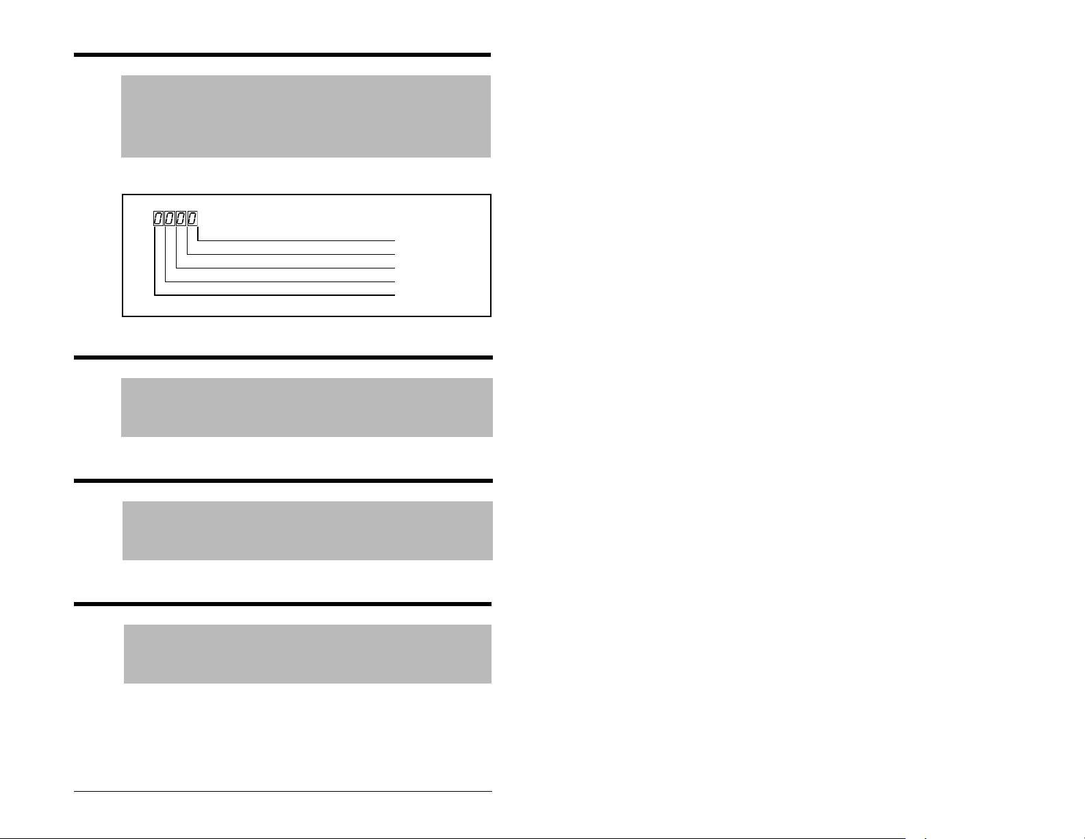
d015 Comm Status
Range: 0 = Condition False
Default: Read Only
See also: A103 through A107
The status of the communications device.
1 = Condition True
See figure 9.14.
Receiving Data Bit 0
Transmitting Data Bit 1
RS485 Option Connected Bit 2
Fault Occurred Bit 3
Figure 9.14 – Comm Status (d015) Bit Definitions
d016 Control SW Version
Range: 1.00 to 99.99
Default: Read Only
See also: N/A
The Main Control Board software version.
d017 Drive Type
Range: 1001 to 9999
Default: Read Only
See also: N/A
Used by Rockwell Automation field service personnel.
d018 Elapsed Ru n Ti me
Range: 0 to 9999 Hours
Default: Read Only
See also: N/A
The accumulated time drive is outputting power. The time is
displayed in 10-hour increments (that is, 1 = 10 hours).
Parameter Descriptions 9-31
Page 82

d019 Testpoint Data
Range: 0 to FFFF
Default: Read Only
See also: A102
The present value of the function selected in Testpoint Select
(A102).
d020 0 - 10 V Analog Input
Range: 0.0 to 100.0%
Default: Read Only
See also: A110, A111
The value present at the drive’s 0 - 10 V analog input.
d021 4 to 20 mA Analog Input
Range: 0.0 to 100.0%
Default: Read Only
See also: A112, A113
The value present at the drive’s 4 - 20 mA analog input.
d024 Drive Temp
Range:
Default: Read Only
See also: N/A
0 to 1200 C
Displays the present operating temperature of the drive power
section.
9-32 MD60 AC Drive User Manual
Page 83

CHAPTER 10
Troubleshooting the Drive
ATTENTION: The drive contains high voltage capacitors that
take time to discharge after removal of mains supply. Before
!
working on the drive, ensure isolation of mains supply from
line inputs [R, S, T (L1, L2, L3)]. Wait three (3) minutes for
capacitors to discharge to safe voltage levels. Darkened
display LEDs is not an indication that capacitors have
discharged to safe voltage levels. Failure to observe this
precaution could result in severe bodily injury or loss of life.
ATTENTION: Only qualified electrical personnel familiar with
the construction and operation of this equipment and the
hazards involved should install, adjust, operate, or service this
equipment. Read and understand this manual and other
applicable manuals in their entirety before proceeding. Failure
to observe this precaution could result in severe bodily injury
or loss of life.
The MD60 constantly monitors its status and provides the following
ways to determine the status of the drive and to troubleshoot
problems that may occur:
• LEDs on the drive (refer to figure 8.1 and table 8.1 for a
description of the LEDs)
• Fault codes
10.1 Fault Codes
Faults codes indicate conditions within the drive that require
immediate attention. The drive responds to a fault by initiating a
coast-to-stop sequence and turning off output power to the motor.
The integral keypad provides visual notification of a fault condition
by displaying the following:
• Flashing fault number (code) on the display. (See table 10.1 for
the fault code descriptions.)
• Flashing FAULT LED
In addition, parameters d007-d009 act as a fault log. See the
parameter descriptions in chapter 9 for more information.
Troubleshooting the Drive 10-1
Page 84

10.1.1 Manually Clearing Faults
Step 1. Note the number of the fault code flashing on the display.
Step 2. Press on the integral keypad to acknowledge the
fault and remove the fault code from the displa y. This also
resets the drive if the fault is cleared.
Step 3. Address the condition that caused the fault. Refer to table
10.1 for a description of the fault and corrective actions.
The cause must be corrected before the fault can be
cleared.
Step 4. After corrective action has been taken, clear the fault and
reset the drive using one of the following methods:
• Press if P037 (Stop Mode) is set to a value
between 0 and 3.
• Cycle drive power.
• Set A100 (Fault Clear) to 1.
• Cycle digital input if A051-A052 (Digital Inx Select) is
set to option 7 (Clear Faults).
10.1.2 Automatically Clearing Faults (Auto Restart
Feature)
The Auto Restart feature provides the ability for the drive to
automatically perform a fault reset followed by a start attempt
without user or application intervention. This allows remote or
“unattended” operation. This feature can only be used for autoresettable faults (see table 10.1).
When this type of fault occurs, and A092 (Auto Restart Tries) is set
to a value greater than “0,” a user-configurable timer, A093 (Auto
Restart Delay), begins. When the timer reaches zero, the drive
attempts to automatically reset the fault. If the condition that caused
the fault is no longer present, the fault will be reset and the drive will
be restarted.
To automatically clear an auto-resettable fault and restart the
drive:
Step 1. Set A092 (Auto Restart Tries) to a value other than 0.
Step 2. Set A093 (Auto Restart Delay) to a value other than 0.
To automatically clear an OverVoltage, UnderVoltage, or
Heatsink OverTemp fault without restarting the drive:
Step 1. Set A092 (Auto Restart Tries) to a value other than 0.
Step 2. Set A093 (Auto Restart Delay) to 0.
10-2 MD60 AC Drive User Manual
Page 85

Use caution when enabling this feature since the drive will attempt
to issue its own start command based on user-selected
programming.
Table 10.1 – Fault Descriptions and Corrective Actions
?
1
No. Fault
F2 Auxiliary
Input
F3 Power Loss N DC bus v oltage
F4 UnderVoltage Y DC bus voltage fell
F5 OverVoltage Y DC bus voltage
F6 Motor Stalled Y Drive is unable to
F7 Motor
Overload
Y Auxiliary input interlock
Y Internal electronic
Description Action
Auto-Reset
is open.
remained below 85%
of nominal.
below the minimum
value.
exceeded maximum
value.
accelerate motor.
overload trip.
• Check remote wiring.
• Verify communications
programming for
intentional fault.
• Monitor the incoming
AC line for low voltage
or line power
interruption.
• Check input fuses.
Monitor the incoming AC
line for low voltage or line
power interruption.
Monitor the AC line for
high line voltage or
transient conditions. Bus
overvoltage can also be
caused by motor
regeneration. Extend the
decel time or install
dynamic brake option.
Increase Accel Time x
(P039, A067) or reduce
load so drive output
current does not exceed
the current set by
parameter A089 (Current
Limit).
• An excessiv e motor load
exists. Reduce load so
drive output current
does not exceed the
current set by parameter
P033 (Motor OL
Current).
• Verify Start Boost
(A084) setting.
Troubleshooting the Drive 10-3
Page 86

Table 10.1 – Fault Descriptions and Corrective Actions (Continued)
?
1
No. Fault
F8 Heatsink
OverTemp
F12 HW
OverCurrent
F13 Ground Fault N A current path to earth
F33 Auto Restart
Tries
F38 Phase U to
Gnd
F39 Phase V to
Gnd
F40 Phase W to
Gnd
F41 Phase UV
Short
F42 Phase UW
Short
F43 Phase VW
Short
Y Heatsink temperature
N The drive output
N Drive unsuccessfully
N A phase to ground fault
N Excessive current has
Description Action
Auto-Reset
exceeds a predefined
value.
current has exceeded
the hardware current
limit.
ground has been
detected at one or
more of the drive
output terminals.
attempted to reset a
fault and resume
running for the
programmed number
of Auto Restart T ries in
A092.
has been detected
between the drive and
motor in this phase.
been detected
between these two
output terminals.
• Check for blocked or
dirty heat sink fins.
Verify that ambient
temperature has not
exceeded 40°C (104 °F)
for IP 30/NEMA 1/UL
T ype 1 installations or 50°C
(122°F) for Open type
installations.
• Check fan.
Check programming.
Check for excess load,
improper Start Boost
(A084) setting, DC brake
volts set too high, or other
causes of excess current.
Check the motor and
external wiring to the drive
output terminals for a
grounded condition.
Correct the cause of the
fault and manually clear.
• Check the wiring
between the drive and
motor.
• Check motor for
grounded phase.
• Replace drive if fault
cannot be cleared.
• Check the motor and
drive output terminal
wiring for a shorted
condition.
• Replace drive if fault
cannot be cleared.
10-4 MD60 AC Drive User Manual
Page 87

Table 10.1 – Fault Descriptions and Corrective Actions (Continued)
?
1
No. Fault
F48 Params
Defaulted
F63 SW
OverCurrent
F64 Drive
Overload
F70 Power Unit N Failure has been
F81 Comm Loss N RS485 port stopped
N The drive was
Y Programmed A098
N Drive rating of 150%
Description Action
Auto-Reset
commanded to write
default values to
EEPROM.
(SW Current Trip) has
been exceeded.
for 1 minute has been
exceeded.
detected in the drive
power section.
communicating.
• Clear the fault or cycle
• Program the drive
Check load requirements
and A098 (SW Current
Trip) setting.
Reduce load or extend
Accel Time.
• Cycle power.
• Replace drive if fault
• If module was not
power to the drive.
parameters as needed.
cannot be cleared.
intentionally
disconnected, check
wiring to the port .
Replace wiring, port
expander, module or
complete drive as
required.
• Check connection.
• A module was
intentionally
disconnected.
• Turn off using A105
(Comm Loss Action).
F100 Parameter
Checksum
F122 I/O Board Fail N Failure has been
1
Refer to section 10.1.2 for information about the Auto Restart Feature.
N The checksum read
from the board does
not match the
checksum calculated.
detected in the drive
control and I/O section.
Set P041 (Reset to
Defaults) to option 1
(Reset Defaults).
• Cycle power.
• Replace drive if fault
cannot be cleared.
Troubleshooting the Drive 10-5
Page 88

10.2 Troubleshooting Tables
Use the following tables to troubleshoot the drive. If you cannot
resolve the problem using these tables, contact Reliance Electric.
10.2.1 Problem: Drive Does Not Start From Terminal
Block Start or Run Inputs
Table 10.2 – Problem: Drive Does Not Start From Terminal Block Start or Run Inputs
Possible Cause(s) Indication Corrective Action
Drive is faulted Flashing red
FAULT LED
Incorrect programming.
None Check parameter settings.
• P036 (Start Source) is set
to option 0 (Keypad) or
option 5 (RS485 Port).
• A051/A052 (Digital Inx
Select) is set to option 5
“Local” and the input is
active.
Incorrect input wiring. See
figure 6.2 for wiring
examples.
None Wire inputs correctly and/or
• 2-wire control requires
Run Forward, Run
Reverse or Jog input.
• 3-wire control requires
Start and Stop inputs
• Stop input is always
required.
Clear fault by using one of
the following methods:
• Press Stop
• Cycle power
• Set A100 (Fault Clear) to
1 (Clear Faults)
• Cycle digital input if A051/
A052 (Digital Inx Select)
is set to option 7 (Clear
Fault).
install jumper.
10-6 MD60 AC Drive User Manual
Page 89

10.2.2 Problem: Drive Does Not Start From Integral
Keypad
Table 10.3 – Problem: Drive Does Not Start From Integral Keypad
Cause(s) Indication Corrective Action
Integral keypad is not
enabled.
Start Key
Status LED is
not on.
• Set parameter P036
(Start Source) to option 0
(Keypad).
• Set parameter A051/A052
(Digital Inx Select) is set
to option 5 (Local) and
activate the input.
I/O Terminal 01 “Stop” input
is not present.
None Wire inputs correctly and/or
install jumper.
10.2.3 Problem: Drive Does Not Respond to Changes
in Speed Command
Table 10.4 – Problem: Drive Does Not Respond to Changes in Speed Command
Cause(s) Indication Corrective Action
No value is coming from
the source of the
command.
The RUN
LED is on and
output is 0
Hz.
• Check d012 (Control Source)
for correct source.
• If the source is an analog
input, check wiring and use a
meter to check for presence of
signal.
• Check d002 (Commanded
Frequency) to verify correct
command.
Incorrect reference source
is being selected via
remote device or digital
inputs.
None
• Check d012 (Control Source)
for correct source.
• Check d014 (Digital Input
Status) to see if inputs are
selecting an alternate source.
Verify settings for A051/A052
(Digital Inx Select).
• Check P038 (Speed
Reference) for the source of
the speed reference.
Reprogram as necessary.
• Review the Speed Reference
Control chart in section 6.6.
Troubleshooting the Drive 10-7
Page 90

10.2.4 Problem: Motor and/or Drive Will Not
Accelerate to Commanded Speed
Table 10.5 – Problem: Motor and/or Drive Will Not Accelerate to Commanded Speed
Cause(s) Indication Corrective Action
Acceleration time is
excessive.
Excess load or short
acceleration times force the
drive into current limit,
slowing or stopping
acceleration.
None Reprogram P039 (Accel Time
1) or A067 (Accel Time 2).
None
• Compare d003 (Output
Current) with A089 (Current
Limit).
• Remove excess load or
reprogram P039 (Accel
Time 1) or A067 (Accel
Time 2).
• Check for improper A084
(Start Boost) setting.
Speed command source or
value is not as expected.
None
• Verify d002 (Commanded
Frequency).
• Check d012 (Control
Source) for the proper
Speed Command.
Programming is preventing
the drive output from
exceeding limiting values.
None Check P035 (Maximum
Frequency) to ensure that
speed is not limited by
programming.
10.2.5 Problem: Motor Operation is Unstable
Table 10.6 – Problem: Motor Operation is Unstable
Cause(s) Indication Corrective Action
Motor data was incorrectly
entered.
10-8 MD60 AC Drive User Manual
None 1. Correctly enter motor
nameplate data into P031,
P032 and P033.
2. Enable A097
(Compensation).
3.Use A084 (Start Boost) to
reduce boost level.
Page 91

10.2.6 Problem: Drive Will Not Reverse Motor
Direction.
Table 10.7 – Problem: Drive Will Not Reverse Motor Direction
Cause(s) Indication Corrective Action
Digital input is not selected
for reversing control.
Digital input is incorrectly
wired.
Motor wiring is improperly
phased for reverse.
Reverse is disabled. None Check A095 (Reverse
None Check (Digital Inx Select).
Choose correct input and
program for reversing mode.
None Check input wiring.
None Switch two motor leads.
Disable).
Troubleshooting the Drive 10-9
Page 92

10-10 MD60 AC Drive User Manual
Page 93

APPENDIX A
Technical Specifications
Environment
Altitude: 1000 m (3300 ft) maximum without derating
Ambient Operating
Temperature
Without Derating:
Storage
Temperature (all
const.):
Relative Humidity: 0% to 95%, non-condensing
Shock (Operating): 15 G peak for 11 ms duration (+/-1.0 ms)
Vibration
(Operating):
Control
Carrier Frequency: 2-16 kHz. Drive rating based on 4 kHz.
Frequency Accuracy • Digital Input: Within +/-0.05% of set output
Speed Regulation Open Loop with Slip
Compensation:
Stop Modes: Multiple programmable stop modes including: Ramp,
Accel/Decel: Two independentl y pro grammable accel and decel
Intermittent
Overload
Electronic Motor
Overload Protection:
IP 20: -10° C (14° F) to 50° C (122° F)
NEMA 1/IP30: -10° C (14° F) to 40° C (104° F)
-40° C (-40° F) to 85° C (185° F)
1 G peak, 5 to 2000 Hz
frequency.
• Analog Input: Within 0.5% of maximum output
frequency.
+/-2% of base speed across a 40:1 speed range.
Coast, DC-Brake, Ramp-to-Hold, and S Curve.
times. Each time may be programmed from 0-600
seconds in 0.1 second increments.
• 150% Overload capability for up to 1 minute.
• 200% Overload capacity for up to 3 seconds
Class 10 protection with speed-sensitive response.
Technical Specifications A-1
Page 94

Input/Output Rating
Output Frequency: 0-240 Hz (Programmable)
Efficiency: 97.5% (Typical)
Digital Control Inputs (Inputs Current = 6 mA)
SRC (Source)
Mode:
18-24 V = ON
0-6 V = OFF
SNK (Sink) Mode: 0-6 V = ON
18-24 V = OFF
Analog Control Inputs
4-20 mA Analog: 250 ohm input impedance
0-10 V DC Analog: 100k ohm input impedance
External Pot: 1-10 k ohms, 2 Watt minimum
Control Output
Programmable Output (form C relay)
Resistive Rating: 3.0 A at 30 V DC, 3.0 A at 125 V AC, 3.0 A at
240 V AC
Inductive Rating: 0.5 A at 30 V DC, 0.5 A at 125 V AC, 0.5 A at
240 V AC
Fuses and Circuit Breakers
Recommended
Fuse Type:
UL Class J, CC, T or Type BS88; 600 V (550 V) or
equivalent.
Recommended
HMCP circuit breakers or equivalent.
Circuit Breakers:
Protective Features
Motor Protection:
2
I
t overload protection - 150% for 60 sec, 200% for
3 sec (Provides Class 10 protection)
Overcurrent: 200% hardware limit, 300% instantaneous fault
Over Volta ge: • 100-120 V AC Input – Trip occurs at 405 V DC bus
voltage (equivalent to 150 V AC incoming line
• 200-240 V AC Input – Trip occurs at 405 V DC bus
voltage (equivalent to 290 V AC incoming line)
• 380-460 V AC Input – Trip occurs at 810 V DC bus
voltage (equivalent to 575 V AC incoming line)
A-2 MD60 AC Drive User Manual
Page 95

Under Voltage: • 100-120 V AC Input – Trip occurs at 210 V DC bus
voltage (equivalent to 75 V AC incoming line)
• 200-240 V AC Input – Trip occurs at 210 V DC bus
voltage (equivalent to 150 V AC incoming line
• 380-480 V AC Input – Trip occurs at 390 V DC bus
voltage (equivalent to 275 V AC incoming line)
Control Ride-
Minimum ride-through is 0.5 sec - typical value 2 sec
Through:
Faultless Power
100 milliseconds
Ride-Through:
Dynamic Braking
Internal brake IGBT included with all ratings.
Approvals
D
9
E
6
T
6
S
X
I
L
U
UL508C
L
®
I
N
Q
D
E
C
T
O
N
D
9
E
6
T
6
S
X
I
L
U
CSA 22.2
L
C
®
I
N
Q
D
E
C
T
O
N
EMC Directive 89/336
LV: EN 50178, EN 60204
EMC: EN 61800-3, EN 50081-1, EN 50082-2
Technical Specifications A-3
Page 96

A-4 MD60 AC Drive User Manual
Page 97

APPENDIX B
Record of
User Settings
B.1 Basic Parameter Group
Default
No. Parameter Name
P031 Motor NP Volts Varies 9-2
P032 Motor NP Hertz 60 Hz 9-2
P033 Motor OL Current Varies 9-2
P034 Minimum Frequency 0 Hz 9-2
P035 Maximum Frequency 60 Hz 9-2
P036 Start Source 0 = Keypad 9-3
P037 Stop Mode 1 = Coast,
P038 Speed Reference 0 = Drive
P039 Accel Time 1 5.0 sec 9-7
P040 Decel Time 1 5.0 sec 9-7
P041 Reset to Defaults 0 = Idle State 9-7
Value
Clear Fault
Potentiome ter
Page
No. User Setting
9-5
9-6
Record of User Settings B-1
Page 98

B.2 Advanced Parameter Group
Default
No. Parameter Name
A051 Digital In1 Select 4 = Preset
A052 Digital In2 Select 4 = Preset
A055 Relay Output Select 0 = Ready (Not
A056 Relay Output Level 0.0 9-11
A067 Accel Time 2 10.0 sec 9-11
A068 Decel Time 2 10.0 sec 9-12
A069 Internal Frequency 0.0 Hz 9-12
A070 Preset Frequency 0 0.0 Hz 9-13
A071 Preset Frequency 1 0.0 Hz 9-13
A072 Preset Frequency 2 0.0 Hz 9-13
A073 Preset Frequency 3 0.0 Hz 9-13
A078 Jog Frequency 10.0 Hz 9-13
A079 Jog Accel/Decel 10.0 sec 9-13
A080 DC Brake Time 0.0 sec 9-14
A081 DC Brake Level Amps x 0.5 9-14
A082 DB Resistor Select 0 = Disabled 9-15
A083 S Curve% 0% (Disabled) 9-15
A084 Start Boost 8 = 5.0 9-16
A088 Maximum Voltage Rated Volts 9-17
A089 Current Limit Amps x 1.8 9-17
A090 Motor OL Select 0 = No Derate 9-17
A091 PWM Frequency 4.0 kHz 9-18
A092 Auto Restart Tries 0 9-18
A093 Auto Restart Delay 1.0 sec 9-19
A094 Start At Power Up 0 = Disabled 9-19
A095 Reverse Disable 0 = Reverse
A096 Flying Start Enable 0 = Disabled 9-20
A097 Compensation 1 = Electrical 9-20
A098 SW Current Trip 0.0 (Disabled) 9-21
A099 Process Factor
(Display Scaling)
Value
Frequencies
Frequencies
Faulted)
Enabled
30.0 9-21
Page
No. User Setting
9-8
9-8
9-9
9-19
B-2 MD60 AC Drive User Manual
Page 99

No. Parameter Name
Default
Value
Page
No. User Setting
A100 Fault Clear 0 = Ready 9-21
A101 Program Lock 0 = Unlocked 9-21
A102 Testpoint Select 0000 9-22
A103 Comm Data Rate 4 = 19.2 K 9-22
A104 Comm Node Address 1 9-22
A105 Comm Loss Action 0 = Fault 9-22
A106 Comm Loss Time 5.0 9-23
A107 Comm Format 0 = RTU 8-N-1 9-23
A110 0 - 10 V Analog Input
0.0% 9-24
Low
A111 0 - 10 V Analog Input
100.0% 9-24
High
A112 4 - 20 mA Analog Input
0.0% 9-25
Low
A113 4 - 20 mA Analog Input
100.0% 9-25
High
A114 Slip Compensation 2.0 Hz 9-25
A115 Process Time Lo 0.00 9-26
A116 Process Time Hi 0.00 9-26
Record of User Settings B-3
Page 100

B-4 MD60 AC Drive User Manual
 Loading...