

Page 1

ANORAD
LZ Series Linear Motors
USER MANUAL
Publication LZ-UM001A-EN-P
January 2008
Page 2
Important User Information
Solid state equipment has operational characteristics differing from those of
electromechanical equipment. Safety Guidelines for the Application, Installation and
Maintenance of Solid State Controls, publication SGI-1.1, available from your local
Rockwell Automation sales office or online at http://literature.rockwellautomation.com
. It
describes some important differences between solid state equipment and hard-wired
electromechanical devices. Because of this difference, and also because of the wide
variety of uses for solid state equipment, all persons responsible for applying this
equipment must satisfy themselves that each intended application of this equipment is
acceptable.
In no event will Rockwell Automation, Inc. be responsible or liable for indirect or
consequential damages resulting from the use or application of this equipment.
The examples and diagrams in this manual are included solely for illustrative purposes.
Because of the many variables and requirements associated with any particular
installation, Rockwell Automation, Inc. cannot assume responsibility or liability for actual
use based on the examples and diagrams.
No patent liability is assumed by Rockwell Automation, Inc. with respect to use of
information, circuits, equipment, or software described in this manual.
Reproduction of the contents of this manual, in whole or in part, without written
permission of Rockwell Automation, Inc., is prohibited.
Throughout this manual, when necessary, we use notes to make you aware of safety
considerations.
WARNING
Identifies information about practices or circumstances that can
cause an explosion in a hazardous environment, which may lead to
personal injury or death, property damage, or economic loss.
IMPORTANT
ATTENTION
Identifies information critical for successful application and
understanding of the product.
Identifies information about practices or circumstances that can lead
to personal injury or death, property damage, or economic loss.
Attentions help you identify a hazard, avoid a hazard and recognize
the consequences.
SHOCK HAZARD
Labels may be on or inside the equipment, for example, a drive or
motor, to alert people that dangerous voltage may be present.
BURN HAZARD
Labels may be on or inside the equipment, for example, a drive or
motor, to alert people that surfaces may reach dangerous
temperatures.
Allen-Bradley, CompactLogix, ControlLogix, DriveExplorer, Kinetix, MP-Series, Rockwell Automation, RSLogix, RSLogix 5000, SoftLogix,
SCANport, and Ultra3000 are trademarks of Rockwell Automation, Inc.
Trademarks not belonging to Rockwell Automation are property of their respective companies.
Page 3

Understanding and Caring for Your
Linear Motor
Installation
Table of Contents
Preface
About This Publication . . . . . . . . . . . . . . . . . . . . . . . . . . . . . . . . . . . . . . 5
Who Should Use This Manual. . . . . . . . . . . . . . . . . . . . . . . . . . . . . . . . . 5
Additional Resources . . . . . . . . . . . . . . . . . . . . . . . . . . . . . . . . . . . . . . . . 5
Chapter 1
Introduction . . . . . . . . . . . . . . . . . . . . . . . . . . . . . . . . . . . . . . . . . . . . . . . 7
Product Description. . . . . . . . . . . . . . . . . . . . . . . . . . . . . . . . . . . . . . . . . 7
Motor Features. . . . . . . . . . . . . . . . . . . . . . . . . . . . . . . . . . . . . . . . . . 8
Identifying Your Linear Motor Components . . . . . . . . . . . . . . . . . . . . . 9
Maintenance . . . . . . . . . . . . . . . . . . . . . . . . . . . . . . . . . . . . . . . . . . . . . . 10
Motor Storage. . . . . . . . . . . . . . . . . . . . . . . . . . . . . . . . . . . . . . . . . . . . . 10
Chapter 2
Introduction . . . . . . . . . . . . . . . . . . . . . . . . . . . . . . . . . . . . . . . . . . . . . . 11
Unpacking and Inspection. . . . . . . . . . . . . . . . . . . . . . . . . . . . . . . . . . . 11
Installing the Linear Motor . . . . . . . . . . . . . . . . . . . . . . . . . . . . . . . . . 12
Mount the Magnet Channel. . . . . . . . . . . . . . . . . . . . . . . . . . . . . . . 12
Motor Coil Mounting Hardware Requirements. . . . . . . . . . . . . . . 14
Mount the Motor Coil . . . . . . . . . . . . . . . . . . . . . . . . . . . . . . . . . . . 15
Motor Power and Feedback Cable Signal Names . . . . . . . . . . . . . . . . 15
Motor-Hall Phasing and Sequence . . . . . . . . . . . . . . . . . . . . . . . . . . . . 17
Positive Motor Direction. . . . . . . . . . . . . . . . . . . . . . . . . . . . . . . . . . . . 18
Motor Coil Thermal Protection. . . . . . . . . . . . . . . . . . . . . . . . . . . . . . . 19
Operational Guidelines . . . . . . . . . . . . . . . . . . . . . . . . . . . . . . . . . . . . . 20
Chapter 3
Troubleshooting
Introduction . . . . . . . . . . . . . . . . . . . . . . . . . . . . . . . . . . . . . . . . . . . . . . 21
Hall Effect Module. . . . . . . . . . . . . . . . . . . . . . . . . . . . . . . . . . . . . . . . . 21
Hall Effect Circuit - Hall Signals Test. . . . . . . . . . . . . . . . . . . . . . . 21
Hall to Back EMF Phasing . . . . . . . . . . . . . . . . . . . . . . . . . . . . . . . 22
PTC Thermal Signal. . . . . . . . . . . . . . . . . . . . . . . . . . . . . . . . . . . . . . . . 22
Motor Coil Electrical Test . . . . . . . . . . . . . . . . . . . . . . . . . . . . . . . . . . . 23
Motor Back EMF Tests . . . . . . . . . . . . . . . . . . . . . . . . . . . . . . . . . . . . . 24
Back EMF Wave Comparison Test . . . . . . . . . . . . . . . . . . . . . . . . 24
Check Measured Back EMF to Specification. . . . . . . . . . . . . . . . . 25
Checking the Magnet Channel Butting Polarity . . . . . . . . . . . . . . . . . . 26
Chapter 4
Hall Effect Module Removal and
Replacement
3 Publication LZ-UM001A-EN-P - January 2008
Introduction . . . . . . . . . . . . . . . . . . . . . . . . . . . . . . . . . . . . . . . . . . . . . . 29
Hall Effect Module. . . . . . . . . . . . . . . . . . . . . . . . . . . . . . . . . . . . . . . . . 29
Remove the Hall Effect Module . . . . . . . . . . . . . . . . . . . . . . . . . . . 29
Install the Hall Effect Module. . . . . . . . . . . . . . . . . . . . . . . . . . . . . 29
Page 4

4
Specifications and Dimensions
Mounting Bolts and Torque Values
Index
Appendix A
Introduction . . . . . . . . . . . . . . . . . . . . . . . . . . . . . . . . . . . . . . . . . . . . . . 31
Trapezoidal Hall Effect Circuit. . . . . . . . . . . . . . . . . . . . . . . . . . . . 32
Positive Temperature Coefficient (PTC) Thermistor . . . . . . . . . . 32
Environmental Specifications for LZ Linear Motors . . . . . . . . . . 32
LZ Series Linear Motor Dimensions. . . . . . . . . . . . . . . . . . . . . . . . . . . 33
Appendix B
Introduction . . . . . . . . . . . . . . . . . . . . . . . . . . . . . . . . . . . . . . . . . . . . . . 57
Publication LZ-UM001A-EN-P - January 2008
Page 5
Read this preface to familiarize yourself with the manual.
Preface
About This Publication
Who Should Use This Manual
This manual provides detailed installation instructions for mounting, wiring,
maintaining, and troubleshooting your LZ Linear Motor.
This manual is intended for engineers or technicians directly involved in the
installation, wiring, and maintenance of this LZ linear motor. Any person that
teaches, operates, maintains, or repairs these linear motors must be trained and
demonstrate the competence to safely perform the assigned task.
If you do not understand linear motors, contact your local Anorad/Rockwell
Automation sales representative for information on available training courses
before using this product.
Read this entire manual before you attempt to install your LZ linear motor into
your motion system. This will familiarize you with the linear motor
components, their relationship to each other and the system.
After installation, check the configuration of the system parameters to be sure
they are properly set for using the linear motor in your motion system.
Be sure to follow all instructions carefully and pay special attention to safety
concerns.
Additional Resources
Resource Description
Kinetix 2000 Multi-axis Servo Drive User Manual,
publication 2093-UM001
Kinetix 6000 Multi-axis Servo Drive User Manual,
publication 2094-UM001
LZ Family of Linear Motors Brochure, publication
PMC-BR001
Ultra3000 Installation Manual, publication
2098-IN003
The following documents contain additional information concerning related
Anorad and Allen-Bradley products.
Information on wiring, configuring, operating, and
troubleshooting a Kinetix 2000 drive.
Information on wiring, configuring, operating, and
troubleshooting a Kinetix 6000 drive.
Provide detailed specifications and ordering information for
the LZ series linear motors.
Information on wiring, configuring, operating, and
troubleshooting a Ultra3000 drive.
5 Publication LZ-UM001A-EN-P - January 2008
Page 6

6
Publication LZ-UM001A-EN-P - January 2008
Page 7

Chapter
Understanding and Caring for Your Linear Motor
1
Introduction
Product Description
The LZ Linear Motor Series description and maintenance is given in this
section. Product features are explored and the part numbering system is
explained. This information will help you develop an understanding of the
linear motor’s basic configuration.
Topic Page
Product Description 7
Identifying Your Linear Motor Components 9
Maintenance 10
Motor Storage 10
The LZ Linear Motor diagram on page 8 shows the LZ linear motor major
components.
Anorad's LZ Series of epoxy core linear motors are made with the latest
magnetic materials and optimized by Finite Element Analysis (FEA) achieving
a very high force density. The LZ Linear Motors are available in models with
continuous forces from 68 N…850 N (15 lbf …191 lbf), and peak forces from
342 N…4250 N (77 lbf … 955 lbf).
7 Publication LZ-UM001A-EN-P - January 2008
Page 8
8 Understanding and Caring for Your Linear Motor
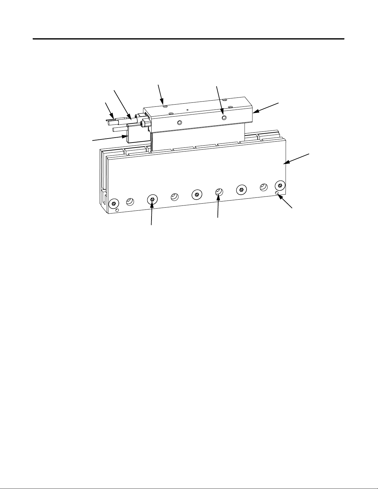
LZ Linear Motor
Coil Power Cable
Thermistor Cable
Hall Effect Module
(Optional)
Coil Assembly Top
Mounting Holes (x 4)
Never attempt to disassemble
magnet channel
Coil Assembly Side
Mounting Holes (x 2)
Through Holes for mounting
Magnet Channel Assembly
Coil Assembly
Magnet Channel
Assembly
For use with
Magnet Channel Alignment Tool
(x2)
For servo drives that require commutation feedback, an optional trapezoidal
(digital) Hall effect feedback module may be attached to the front of the motor
coil. The LZ linear motor may also be commutated via software. Anorad and
Rockwell Automation offers a full line of compatible servo controls and drives.
Motor Features
• High-performance, optimized design.
• 30% higher force density as compared to standard ironless motors.
• Zero-cogging.
• Wide range of coil and magnet options.
• Peak force range from 350…4000 N.
• Continuous force from 70…900 N.
• Ideal for constant scanning application.
Publication LZ-UM001A-EN-P - January 2008
Page 9
Understanding and Caring for Your Linear Motor 9
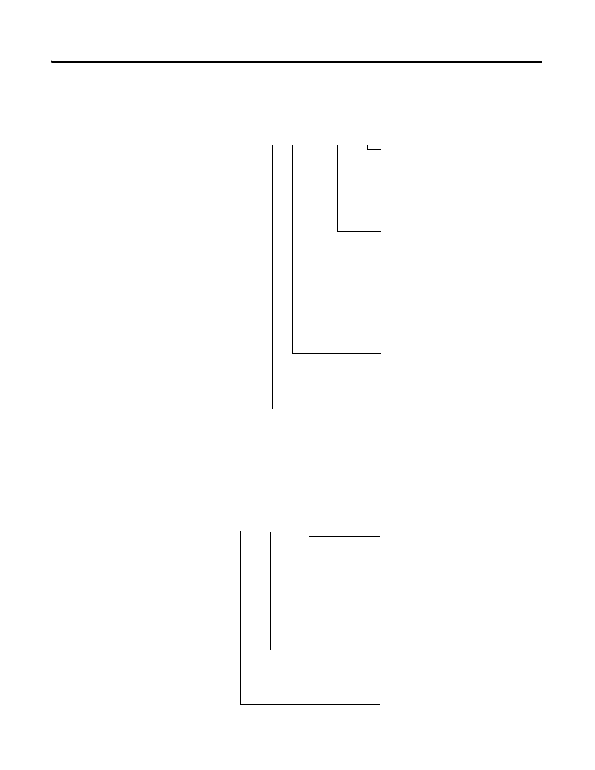
Identifying Your Linear Motor Components
Use the following key to identify your linear stage and its options coil and
magnet assemblies.
LZ - xxx - x - xxx - x - x - x - xx - x
Cable Length
0 = 300 mm,
1 = 600 mm,
2 = 1000 mm
Thermal Protection
0 = None
TR = PTC Thermal Sensor
Hall Feedback
0 = No Feedback
T = Trapezoidal Hall Effect
Cooling Option
0 = No Cooling
Winding Code
D = Y Configuration
E = Y Configuration
Δ Configuration
F =
G = Δ Configuration
Coil Length
120 = 120 mm
240 - 240 mm
360 = 360 mm
480 = 480 mm
Configuration
0 = Match to ’0’ Option Magnet Channel
T = Match to ’T’ Option Magnet Channel
HT = Match to ’HT’ Option Magnet Channel
Magnet Length
030 = 30 mm
050 = 50 mm
075 = 75 mm
100 = 100 mm
Bulletin Number
LZM - xxx - x - xxx
Magnet Channel Length
120 = 120mm,
180 = 180mm
240 = 240mm
480 = 480mm
600 = 600mm
Configuration
0 = Match to ’0’ Option Coil
T = Match to ’T’ Option Coil
HT = Match to ’HT’ Option Coil
Magnet Length
030 = 30 mm
050 = 50 mm
075 = 75 mm
100 = 100 mm
Bulletin Number
Publication LZ-UM001A-EN-P - January 2008
Page 10

10 Understanding and Caring for Your Linear Motor
Maintenance
Motor Storage
Anorad linear motors require no maintenance when operated in a relatively
clean environment. For operation in harsh and dirty environments, minimal
cleaning is recommended every 6 months.
Clean the metallic debris and other contaminants from the air gap. To
effectively remove the metal debris use a strip of masking tape. Simply put a
strip of tape in the magnet channel and then remove it.
Keeping the magnet channel clean will prevent witness marks. Witness marks
are caused by metal debris being dragged across the surface of the magnet by
the magnet field of the moving coil. Witness marks have no effect on the
performance of the motor.
Store the motor in a clean, dry, and vibration free environment it should be
kept at relatively constant temperature. The coil resistance measurement
checks explained in this manual should be done at time of storage. If a motor
is stored on the equipment, it should be protected from the weather.
Publication LZ-UM001A-EN-P - January 2008
Page 11
Installation
Chapter
2
Introduction
Unpacking and Inspection
Use the following section to guide you through installation and start-up of
your LZ linear motor.
Topic Page
Unpacking and Inspection 12
Installing the Linear Motor 12
Motor Power and Feedback Cable Signal Names 15
Motor-Hall Phasing and Sequence 17
Positive Motor Direction 18
Motor Coil Thermal Protection 19
Operational Guidelines 20
Inspect motor assemblies for damage that may have occurred in shipment.
Any damage or suspected damage should be immediately documented. Claims
for damage due to shipment are usually made against the transportation
company. Contact Anorad immediately for further advise.
ATTENTION
Linear motors contain powerful permanent magnets which
require extreme caution during handling. When handing
multiple magnet channels do not allow the channels to come in
contact with each other. Do not disassemble the magnet
channels. The forces between channels are very powerful and
can cause bodily injury. Persons with pacemakers or Automatic
Implantable Cardioverter Defibrillator (AICD) should maintain a
minimum distance of 0.33 m (1 ft) from magnet assemblies.
Additionally, unless absolutely unavoidable, a minimum
distance of 1.5 m (5 ft) feet must be maintained between
magnet assemblies and other magnetic or ferrous composite
materials. Use only non-metallic instrumentation when
verifying assembly dimension prior to installation
• Compare the purchase order with the packing slip.
• Check the quantity of magnet channels received matches your job
requirements.
• Identify the options that came with your linear motor.
• Inspect the assemblies and confirm the presence of specified options.
11 Publication LZ-UM001A-EN-P - January 2008
Page 12
12 Installation
Installing the Linear Motor
Use the following procedures to install the magnet channel and the motor coil
to create a linear motor.
Mount the Magnet Channel
The required tools are:
Use M6 SHCS for channel mounting configuration A, or M5 SHCS for
channel mounting configuration B and C see diagram on page 14. See
Specifications and Dimensions starting on page 31 for quantity.
Use the follow steps to safely install your magnet channel on to the mounting
surface.
• magnet channel alignment tool (supplied).
• aluminum straight edge.
• non-magnetic M4 or M5 hex wrench.
ATTENTION
To avoid injury or damage from unexpected motion of the
channel caused by the magnetic attraction between channels,
maintain a minimum distance of 1.2 m (5 ft) between the
channel that are being installed and the channels awaiting
installation. Leave protective cardboard and conductive metal
plates in place until the installation is performed.
1. Be sure to the mounting surface is clear of any and all of foreign matter.
ATTENTION
If necessary the surface maybe stoned (acetone or methanol may be
used as cleaning agent).
2. Verify the flatness of the surface to which the magnet channel is to be
mounted.
The total indicator reading (TIR) is 0.127 mm (0.005 in.) per 300 mm
(12 in.). TIR or runout, correlates to an overall flatness of a surface.
Do not use abrasives to clean the surface.
Publication LZ-UM001A-EN-P - January 2008
Page 13
Installation 13
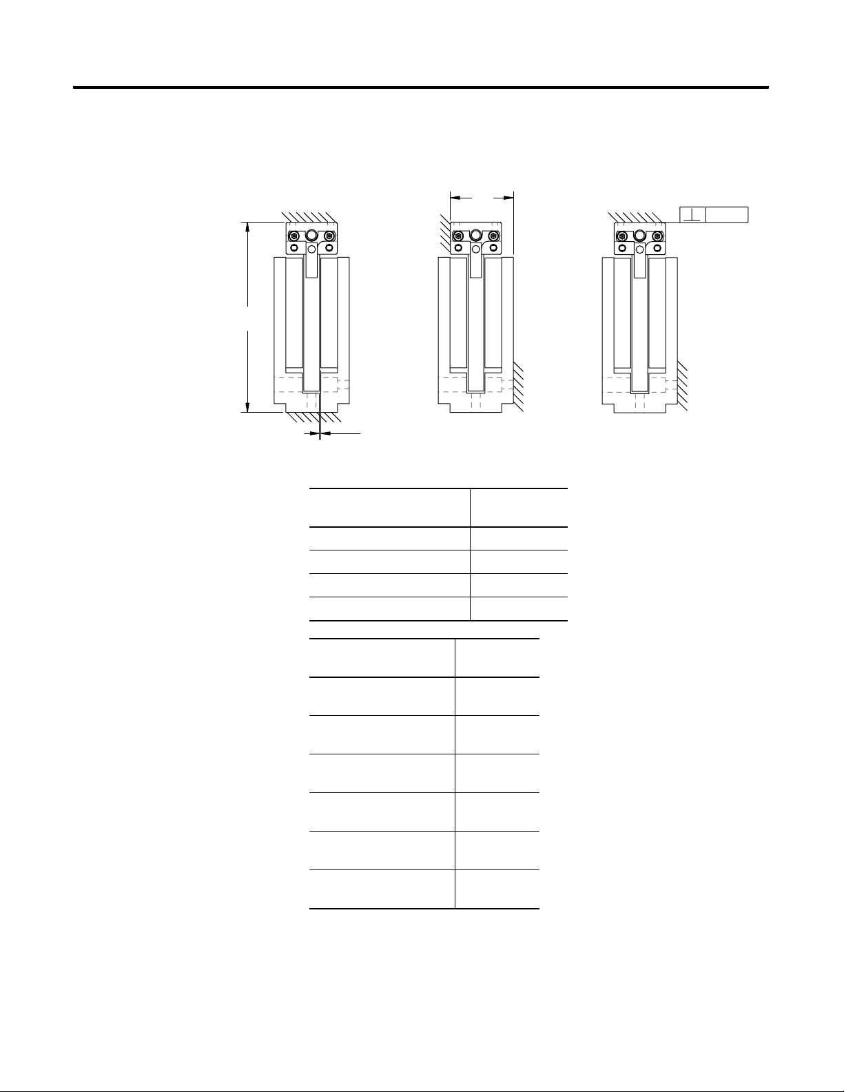
A
B
0.83± 0.40
(0.033
±
0.015)
0.10 (.003)
Mounting Configuration A Mounting Configuration B Mounting Configuration C
3. Verify that the mounting configuration for the magnet channel and coil
fits in envelope dimensions shown in diagram.
Catalog Number A
mm (in.)
LZM-030LZM-050LZM-075LZM-100-
x-xxx-x-x-x-x-x 80.0 (3.15)
x-xxx-x-x-x-x-x 100.0 (3.94)
x-xxx-x-x-x-x-x 130.0 (5.12)
x-xxx-x-x-x-x-x 155.0 (6.10)
Catalog Number B
mm (in.)
LZM-030-0-
xxx-x-x-x-x-x
36.4 (1.43)
LZM-050-0-xxx-x-x-x-x-x
LZM-030-T-
xxx-x-x-x-x-x
37.7 (1.48)
LZM-050-T-xxx-x-x-x-x-x
LZM-030-HT-
xxx-x-x-x-x-x
43.15 (1.70)
LZM-050-HT-xxx-x-x-x-x-x
LZM-075-0-
LZM-100-0-xxx-x-x-x-x-x
LZM-075-T-
xxx-x-x-x-x-x
xxx-x-x-x-x-x
38.05 (1.50)
39.35 (1.55)
LZM-100-T-xxx-x-x-x-x-x
LZM-075-HT-
xxx-x-x-x-x-x
43.15 (1.70)
LZM-100-HT-xxx-x-x-x-x-x
Publication LZ-UM001A-EN-P - January 2008
Page 14
14 Installation
4. Install the first magnet channel using M6 SHCS for mounting
configuration A, or M5 SHCS for mounting configuration B and C.
TIP
Non-magnetic tools and hardware such as beryllium copper,
300 series stainless steel, and others should be used. If not
available, proceed carefully since magnetic and ferrous items
will be attracted to the magnet channel.
5. Do not tighten bolts at this time. Install additional magnet channels by
placing them on the mounting surface at a distance from the previously
installed magnet channel, and then slide it towards its final location.
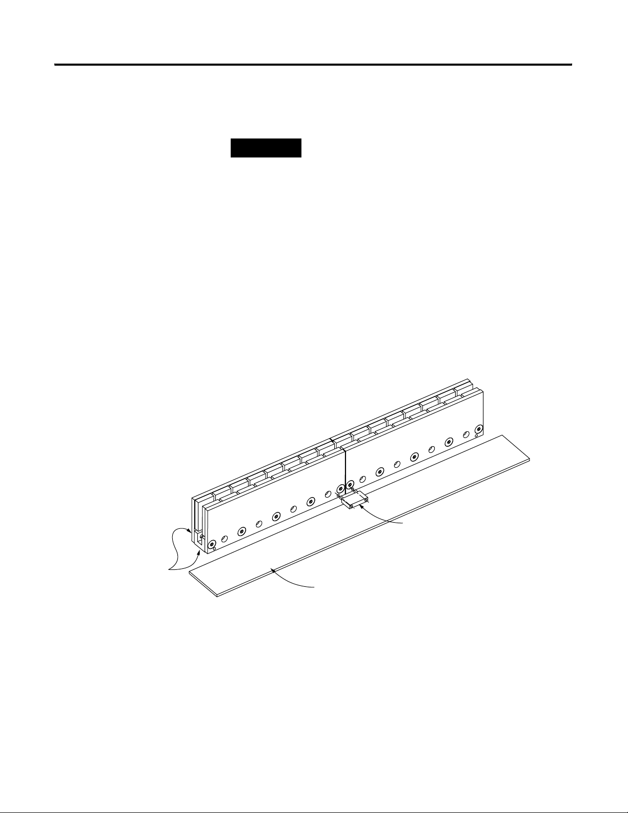
6. The final alignment of the magnet channels is done with an aluminum
straight edge and the alignment tool.
Place the alignment tool in the alignment holes on each of the channels
as shown in diagram. Align the edges of the channel with the aluminum
straight edge and tighten the bolts.
Mounting
Surfaces
Publication LZ-UM001A-EN-P - January 2008
Use magnet channel alignment
tool to set spacing of magnet channels.
(Part Number B91330)
Aluminum Straight Edge
Motor Coil Mounting Hardware Requirements
Select M4 x 0.7 bolts with a length that extends through your machine slide by
5 mm minimum, but not more then
7 mm.
Page 15
Installation 15
Mount the Motor Coil
Follow these procedures to mount the motor coil to your machine slide.
1. Be sure the motor coil mounting face is clean and free of burrs.
2. Position the slide at the end of travel where the cable is to exit.
Motor Power and Feedback
The following tables show the motor power and feedback cable signal names.
These cables are not suitable for continuous flexing operation and should be
Cable Signal Names
terminated and connected to flex type cables for any continuous flex
operation.
3. Using M4 x 0.7 bolts with a length
Mounting Hardware Requirements.
as defined by previously in Motor Coil
Lightly tighten bolts.
4. Using plastic shim stock measure the gap between the motor and
magnet. The gap should be 0.83
± 0.4 (0.033 ± 0.15).
5. Torque all bolts to values listed on the tables in Appendix B. When
considering torque values for mounting hardware, take into account the
magnet channel mounting surface material and mounting hardware.
Secure assemblies in place using all mounting holes.
IMPORTANT
Improper wiring can lead to the motor not responding to
commutation commands, run away conditions, or the motor
performing at about half its specified force.
Motor Power Cable Signals
Color from Motor Designation Comments
Red Motor Phase U (A) • Observe maximum
White Motor Phase V (B)
Black Motor Phase W (C)
Green/Yellow Motor Ground •Terminate per drive
Shield Cable Shield
Publication LZ-UM001A-EN-P - January 2008
applied voltage
specification.
• Consult drive manual or
supplier for specific
wiring instructions to
the drive. Wiring is
phase-commutation
sensitive.
manual instructions.
•Shield is not connected
to the motor frame.
Page 16
16 Installation
ATTENTION
Disconnect the input power supply before installing or servicing
the motor.
The motor lead connections can short and cause damage or
injury if not well secured and insulated.
Insulate the connections, equal to or better than the insulation
on the supply conductors.
Properly ground the motor per the selected drive manual.
Feedback Cable Signals
Signal Type Color from
Module
Trapezoidal
Hall
Effect
Circuit
Shield Silver Brad Cable Shield Terminate at the drive end per the
Thermistor Black
Red +V 5-24Vdc Hall Supply, 20 mA.
Black VRTN Hall signal common.
White S1
Blue S2
Orange S3
Black
Signal
Designation
TR+
TR-
Comment
• Trapezoidal Hall Signals, 120
Spacing, Open Collector
Transistor (24Vmax) Outputs
(Pull-up Resistor External).
• Consult the drive manual or
supplier for specific wiring
instructions to the drive.
Wiring is phase-commutation
sensitive.
drive manual instructions.
Positive Temperature Coefficient
(PTC) thermistor.
o
Publication LZ-UM001A-EN-P - January 2008
Page 17
Installation 17
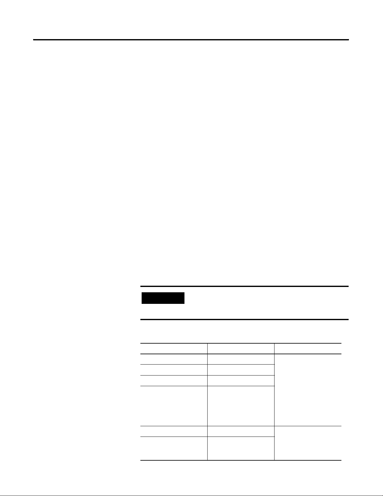
Motor-Hall Phasing and Sequence
The LZ linear motor family is compatible with off-the-shelf brushless motor
servo drives. The servo drive will see them as a two-pole motor with a full
electrical cycle of 60 millimeters (360 degrees equivalent rotary motion).
The brushless motor drives and controls must have two control functions for
suitable commutation of a linear motor.
• Upon power-up, the servo drive must be able learn where the motor
electrical coil phases are with respect to the north and south magnetic
fields, and align its three phase drive current accordingly.
• The servo drive must be able to control the direction and magnitude of
current through the three phases of the coil as it moves across the
magnetic field.
Linear motors with Hall sensors (LZ -xxx-x xxx-x-x-T-x-x) can be used for
Hall commutation feedback with brushless motor servo drives. See the
relationship of the digital Hall signals to the back EMF of the motor coils in
the diagram on page 18. These signals can be used in two ways:
• When using Hall-start-up, upon power-up, the brushless servo drive
reads the state of the three digital Hall signals to approximate the motor
coil location with respect to the magnetic field. The drive then switches
to a fine sinusoidal commutation based on a the high resolution linear
encoder feedback. A high resolution in encoder must be install in your
system to use this feature.
• Some drives will perform trapezoidal commutation based solely on the
feedback from the digital Hall signals.
IMPORTANT
As shown in the phasing diagram:
S1 is in phase with W-U back EMF
S2 is in phase with U-V back EMF
S3 is in phase with V-W back EMF
Phase sequence = S1 leads S2 leads S3. Spacing is 120 degrees.
ATTENTION
IMPORTANT
For optimal commutation and force generation, the selected
brushless servo motor drive must be compatible with the LZ
series phasing, and be wired to the motor coil correctly.
Incorrect motor and Hall wiring can cause runaway conditions.
Phasing direction = the coil toward the motor power cable or
the magnet assembly away from the power cable.
Publication LZ-UM001A-EN-P - January 2008
Page 18
18 Installation
Motor Phasing Diagram
Back EMF Voltage vs. Hall Signals
Back
EMF
Voltage
Digital
Hall
Signals
W-U
U-V
V-W
S1
S2
S3
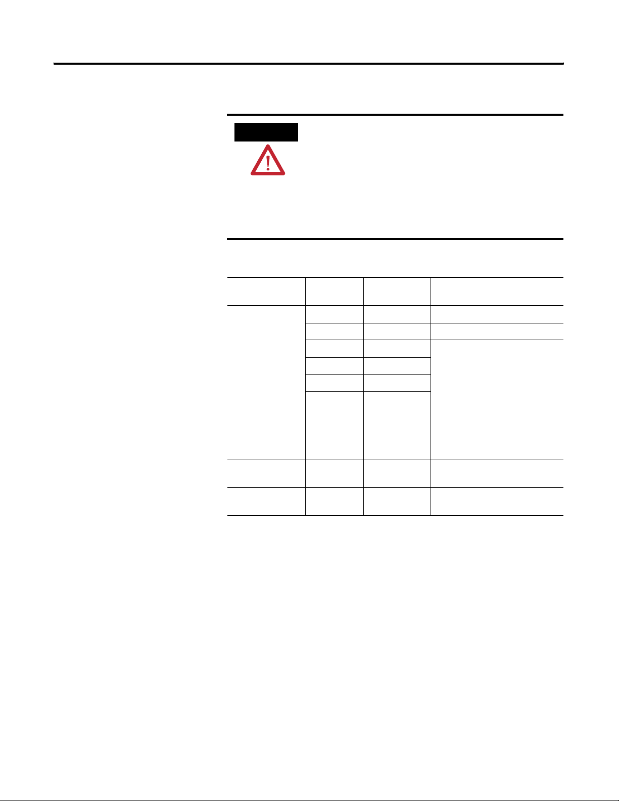
Positive Motor Direction
Linear Travel mm (in.)
0° 60° 120° 180°
60 (2.36)
240°
300°
360°
Phasing direction = the coil toward motor power cable for moving coil
configuration as shown in Positive Motor Direction or the magnet assembly
away from power cable for moving magnet configuration.
When properly wired this is considered the positive direction.
Coil Motion
Stationary Magnet
Publication LZ-UM001A-EN-P - January 2008
Page 19
Installation 19
Motor Coil Thermal Protection
ATTENTION
• Typical digital drives have “RMS” current protection and I
estimated temperature vs. time software protection schemes. These
available features should be activated and set according to the motor
model ratings for there application.
• The selected drive should have
should be set according to the motor’s peak current rating, as a
maximum.
• For drives without adjustable or available motor protection features,
motor fuses (current rating not to exceed motor continuous RMS)
should be installed per the Local and National Electrical Code. The
fuses should be time-delay type and rated for the drive PWM output
voltage.
LZ linear motors with the thermal protection option will supply
a signal that indicates the motor temperature limit condition.
This signal should be used by the motor control or drive system
to immediately shut down the motor power on an open
condition. Since linear motors are generally not repairable, and
typically highly integrated into the mechanical structure,
redundant motor thermal protection is strongly recommended.
± peak current magnitude limits that
2
T or
• Design control circuit to trip at 130°C as necessary.
Temperature °C (°F) Resistance in Ohms
Up to 25 (77) ≤ 300
Up to 125 (257) ≤ 1500
Up to 135 (275) ≥ 4000
Publication LZ-UM001A-EN-P - January 2008
Page 20
20 Installation
Operational Guidelines
After installing the motor and before powering up your system for the first
time, performed the Motor Coil Electrical Test on page 23 to verify motor
condition.
ATTENTION
Moving parts can injure. Before running the motor, make sure
all components are secure and the magnet mounting hardware
is below magnet surface. Remove all unused parts from the
motor travel assembly to prevent them from jamming in the
motor air gap and damaging the coil or flying off and causing
bodily injury.
Run away condition: incorrect motor-hall (commutation) wiring
and position feedback (position encoder) to servo control can
cause uncontrolled speeding.
Keep away from the line of motor travel at all times.
High Voltage can kill. Do not operate with protective covers
removed. Do not go near electrically live parts.
Maximum Safe Speed: Linear motors are capable of very high
forces, accelerations and speeds. The maximum obtainable
acceleration and speed is based on the drive output (bus
voltage and current settings). The allowable maximum speed is
application specific and partly based on the linear motion
mechanics supplied by others.
IMPORTANT
You are responsible for ensuring the servo control system safely
controls the linear motor with regards to maximum safe force,
acceleration and speed, including runaway conditions.
Publication LZ-UM001A-EN-P - January 2008
Page 21

Troubleshooting
Chapter
3
Introduction
Hall Effect Module
Use this section to diagnose the health of motor coil and the Hall effect
module.
Topic Page
Hall Effect Module 21
PTC Thermal Signal 22
Motor Coil Electrical Test 23
Motor Back EMF Tests 24
Checking the Magnet Channel Butting Polarity 26
Use the following procedures to troubleshoot the Hall effect module.
ATTENTION
Even with the motor power disabled and leads disconnected,
permanent magnet motors can generate high back EMF voltage
when moving due to external forces.
Hall Effect Circuit - Hall Signals Test
1. Turn the drive power OFF.
2. Verify the Hall circuit is connected to the drive per interface wiring
specifications.
3. Disconnect the motor leads from the drive.
4. Turn the Hall power supply ON (driver power ON).
5. Using an oscilloscope, while referring to the Motor Phasing Diagram,
check the waveforms at S1, S2 and S3 while slowly and steadily moving
the motor by hand in the specified phasing direction.
21 Publication LZ-UM001A-EN-P - January 2008
Page 22

22 Troubleshooting
6. Check for the proper logic levels (approximately 0V = low, +V = high)
and the sequence: S1 leads S2 leads S3 with approximately 120 electrical
degree spacing in between.
TIP
Connect the probe common to the Hall signal common.
Hall to Back EMF Phasing
1. Turn the drive power OFF.
2. Verify the Hall circuit is connected to the drive per interface wiring
specifications.
3. Disconnect the motor leads from the drive.
4. Turn the Hall power supply ON (driver power ON).
5. While slowly and steadily moving the motor by hand, perform the Hall
Signal Test except this time check the motor phases are in-phase with
the specific Hall signal per the Motor Phasing Diagram. The phase error
between the Hall signal and the in-phase Back EMF should be within
± 5 electrical degrees.
PTC Thermal Signal
IMPORTANT
At ambient room temperature, approximately 25 °C (77 °F), the resistance
measurement between PTC Temp+ and Common should be
The table lists the increase in resistance at higher temperatures outside the
normal operating temperature envelope.
PTC Thermistor Signal Characteristics
Temperature °C (°F) Resistance in Ohms
Up to 25 (77) ≤ 300
Up to 125 (257) ≤ 1500
Up to 135 (275) ≥ 4000
Observe the Back EMF phase polarity.
Back EMF U-V means:
Probe tip on U phase and probe common on V phase
≤ 300 Ω.
Publication LZ-UM001A-EN-P - January 2008
Page 23

Troubleshooting 23
Motor Coil Electrical Test
Perform this test after installation and when a coil electrical fault is suspected.
ATTENTION
Dangerous voltages, forces and energy levels exist in servo
controlled systems. Extreme care must be exercised when
operating, maintaining or servicing the linear motor to prevent
harm to personnel or equipment
1. Ensure the coil is at room temperature, approximately 25
o
C (77 oF).
2. Turn the drive power OFF.
3. Ensure all the motor leads (phases and ground) are disconnected from
the drive.
4. Referring to the diagram, measure the phase to phase (p-p) resistance of
the three phase combinations and record the values. The three readings
should be approximately equal to each other.
Lamination
Frame
R
p-n
R
p-p
U
V
W
Shield
M otor P hases
M otor G round
R
= R
X 2
p-p
p-n
5. Measure the phase to ground resistance for each phase.
The resistance to ground should be in excess of 100 megohms. A lower
reading may indicate an electrical problem.
6. Disconnect the field cable at the coil assembly interface and repeat
procedure.
If any reading is still below 100 megohms, consult Anorad, as the motor
may have an internal electrical problem.
Publication LZ-UM001A-EN-P - January 2008
Page 24

24 Troubleshooting
7. Compare the phase resistance readings to the cold resistance
specification of the specific coil model.
The three reading should be about the same and comparable to the cold
resistance specified for your model. When the coil is hot the resistance
reading should still be balanced and but may be as mush as 30 … 40%
higher than the cold resistance. To rule out the cable resistance,
disconnect the field cable at the coil assembly interface and repeat the
procedures at the coil.
Motor Back EMF Tests
IMPORTANT
When the LZ motor phases are internally connected in a Y configuration
(LZ-xxx-x-xxx-D/E-x-x-x-x). The neutral of the Y is not accessible without
the use of a resistor star network. This is why all measurements are performed
phase-to-phase.
Each phase can consist of single windings (coils) or multiple sets in series or
parallel. Performing a back EMF voltage magnitude and phase sequence test is
a good indicator of correct internal wiring.
Do not perform coil or insulation electrical stress tests (Megger
or Hi-Pot test) without first consulting with Anorad technical
support or engineering.
Back EMF Wave Comparison Test
ATTENTION
Even with the motor power disabled and the leads
disconnected, permanent magnet motors can generate high
back EMF voltage when moving due to external forces.
Publication LZ-UM001A-EN-P - January 2008
1. See the Motor Phasing Diagram on page 18. Certain measurements in
this test will be inverted.
2. Turn the drive power OFF.
3. Disconnect the motor leads from the drive.
4. With a 2 channel oscilloscope, compare U-V to W-V voltage by
connecting the leads, and slowly and steadily moving the motor by hand,
in the phasing direction specified in Motor-Hall Phasing and Sequence.
o
W-V should lead U-V by 60
approximately the same. Note that probe common = V.
. The shapes and peak voltages should be
Page 25

Troubleshooting 25
5. Repeat step 4 comparing V-W to U-W. In this case U-W should lead
o
V-W by 60
. The shapes and peak voltages should be approximately the
same. Note that probe common = W. Be sure to use the same phasing
direction as in step 4.
Check Measured Back EMF to Specification
By comparing your measured and calculated Back EMF constant to the
motor’s specified back EMF constant, you can verify the correct installation
and general health of the magnets and coil. The force constant has a direct
relationship to the back EMF constant, so this test also checks the force
constant. The calculation is based on the analysis of one motor
electromechanical cycle. Problems can occur at any point along the motor
travel, so check that the Back EMF waveshape is consistent throughout the
whole travel.
1. Turn the drive power OFF.
2. Disconnect the motor leads from the drive.
ATTENTION
Even with motor power disabled and leads disconnected,
permanent magnet motors can generate high back EMF voltage
when moving due to external forces.
3. Using a storage oscilloscope, connect one channel across any two phase
leads.
4. Move the motor at a very steady and constant speed in either direction
by hand. This is the motor’s phase-phase back EMF.
5. Capture and analyze one electrical cycle.
V
(pK-pK)
time (s)
one cycle
Publication LZ-UM001A-EN-P - January 2008
Page 26

26 Troubleshooting
Mechanical displacement of one electrical cycle = motor magnetic pitch (180o)
in inches multiplied by two. Note that the published specification may already
be in “cycles.” In this case do not multiply by two.
Use the following equation to calculate back EMF constant:
in
----s
in
-----
ptp[]
s
in
----s
mechanical displacement of one cycle (in)
--------------------------- ------------------------------ ------------------------------- -------------- v e l o c i t y
-------------------------- -------- Back EMF constant
Velocity
Volts
ptz ptp[]
Note:
Where:
ptz = peak to zero or peak of sinewave
ptp = phase to phase
-------------------------- -----------in
-----
s
cycle time (s)
V
ptz
in
----s
0.707× Back EMF constant
=
V
= V
ptz
=
=
(pK-pK)
x 0.5 (V)
Volts
-------------------------- ------------
VoltsRMS ptp[]
--------------------------- ---------------
ptz
When comparing to the published motor back EMF constant, make sure you
convert the units as necessary.
Checking the Magnet Channel Butting Polarity
Publication LZ-UM001A-EN-P - January 2008
If values do not match verify that you have installed the correct magnetic
channel and coil assemblies and they have the correct air gap.
The magnetic channels must be butted such that the magnet polarity sequence
is alternating (north-south) throughout the whole travel. It is difficult to use
the back EMF method to check this on motor coils with multiple sets.
Analyzing the trapezoidal Hall effect signal over the whole travel is the best
method of evaluating proper magnet channel polarity.
1. Refer to the Motor Phasing Diagram for the expected Hall waveshape.
2. With the drive power OFF, verify that the Hall circuit is connected to
the drive per the interface wiring specifications.
3. Disconnect the motor leads from the drive.
4. Turn the Hall power supply ON (driver power ON).
Page 27

Troubleshooting 27
5. Using an oscilloscope, connect one channel between any Hall signal
(output) and the Hall signal common.
6. Slowly and steadily move the motor by hand in one direction over the
whole travel. Monitor the waveshape as you are doing this.
The Hall signal should alternate between a high and low DC level of
equal duty cycle (squarewave), as the Hall module passes over the
alternating polarity magnets. Especially at the magnet channel joints,
ensure the squarewave shape is consistent. Any changes or irregularities
in the squarewave duty cycle shape may indicate a magnet polarity
problem. Note which magnet channel where the problem occurs. If a
problem is suspected, first check to see if the channel alignment tool
holes are all on the same side. If correct, contact Anorad Technical
Support for further advice.
Publication LZ-UM001A-EN-P - January 2008
Page 28

28 Troubleshooting
Publication LZ-UM001A-EN-P - January 2008
Page 29

Chapter
4
Hall Effect Module Removal and Replacement
Introduction
Hall Effect Module
Use this section to change the Hall effect module.
Topic Page
Hall Effect Module 29
If a problem is detected with a Hall effect module use the following
procedures to remove and replace the unit.
The following procedures require a 3 mm hex key, non-magnetic preferred,
and cardboard to fit in magnet channel.
Replacement Hall Effect Modules
Coil
Catalog No.
LZ-xxx-x-xxx-D-x-x-xx-x Y B91860
LZ-xxx-x-xxx-E-x-x-xx-x
LZ-xxx-x-xxx-F-x-x-xx-x Delta B91860-Delta
LZ-xxx-x-xxx-G-x-x-xx-x
Winding
Ty pe
Hall Effect Module
Part Number
Remove the Hall Effect Module
1. Disconnect the Hall cable from the drive.
1. Place the cardboard in the magnet channel to prevent tools from
damaging the magnets by limiting the attractive forces.
2. Remove the two M4 SHCS using a 3 mm hex key.
Install the Hall Effect Module
1. Place the cardboard in the magnet channel to prevent tools from
damaging the magnets by limiting the attractive forces.
29 Publication LZ-UM001A-EN-P - January 2008
Page 30

30 Hall Effect Module Removal and Replacement
2. Place the module at the end of the motor with the sensor blade inserted
in the magnet channel.
3. Install the two M4 SHCS using a 3 mm hex key. Do not over tighten.
4. Remove the cardboard from the magnet channel.
5. Connect the Hall cable connector.
Publication LZ-UM001A-EN-P - January 2008
Page 31

Specifications and Dimensions
Appendix
A
Introduction
Anorad/Rockwell Automation publication listed in Additional Resources on
page 5 may supersede the information in this appendix.
Topic Page
Trapezoidal Hall Effect Circuit 32
Positive Temperature Coefficient (PTC) Thermistor 32
Environmental Specifications for LZ Linear Motors 32
LZ Series Linear Motor Dimensions 33
31 Publication LZ-UM001A-EN-P - January 2008
Page 32

32 Specifications and Dimensions
Trapezoidal Hall Effect Circuit
Description Specifications
Input Power 5…24V dc, 20 mA max.
Output NPN, open collector, 10 mA max.
Hall signal common
• Trapezoidal Hall Signals, 120
Transistor (24V max.) Outputs (Pull-up Resistor
External)
• Consult the drive manual or supplier for specific wiring
instructions to the drive. Wiring is phase-commutation
sensitive.
o
Spacing, Open Collector
Positive Temperature Coefficient (PTC) Thermistor
Temperature °C (°F) Resistance in Ohms
Up to 25 (77) ≤ 300
Up to 125 (257) ≤ 1500
Up to 135 (275) ≥ 4000
Environmental Specifications for LZ Linear Motors
Attribute Value
Ambient temperature 0…40 °C (32…104 °F)
Storage temperature -30…70 °C (-22…158 °F)
Relative humidity 5%…95% non-condensing
Publication LZ-UM001A-EN-P - January 2008
Page 33

Specifications and Dimensions 33
LZ Series Linear Motor Dimensions
26.00
35.00
(1.02)
(1.38)
4.50
(0.18)
Mounting Holes M4 X 0.7 X 7 mm Deep
Typ. B oth Sides Quantity A2 - See table
11.00
(0.433)
Linear motors are designed to metric dimensions. Inch dimensions are
conversions from millimeters. Untolereated dimensions are for reference.
LZ Series Linear Motor Coil (Catalog Number LZ-030-0-xxx-x-0-x-x-x)
Mounting Holes M4 X 0.7 X 8.5 mm Deep
Quantity A1 - See table
F
L
"G"
H
E
D
C
B
A
80.00
(3.15)
60.00
(2.362)
28.00
(1.10)
38.00
(1.496)
5.0
(0.20)
Dimension are in mm (in.)
Thermistor Wires
2
(24 GA)
0.25mm
Power Cable
Ø
6.1 mm (0.24), 0.75 mm2(18 GA)
(Flying Leads)
Optional Hall Eect Module
Ø
6 mm (0.24) Cable
(Flying Leads)
A
See Table
32.00
Y Windings
(1.260)
35.00
Delta Windings
70.5
(2.78)
Magnet Channel
Assembly (Ref.)
0.38 (0.015) A
A
22.0
(0.87)
8.3
(0.33)
80.0
(3.15)
Coil Cat. No. L
mm
(in.)
LZ-030-T-120-x-0-x-x-x 136.00
(5.35)
LZ-030-T-240-x-0-x-x-x 256.00
(10.08)
LZ-030-T-360-x-0-x-x-x 376.00
(14.80)
LZ-030-T-420-x-0-x-x-x 496.00
(19.53)
A
mm
(in.)
120.00
(4.724)
120.00
(4.724)
120.00
(4.724)
B
mm
(in.)
200.00
(7.874)
200.00
(7.874)
200.00
(7.874)
C
mm
(in.)
240.00
(9.449)
240.00
(9.449)
D
mm
(in.)
320.00
(12.598)
320.00
(12.598)
E
mm
(in.)
360.00
(14.173)
F
mm
(in.)
440.00
(17.323)
G
mm
(in.)
60.00
(2.362)
180.00
(7.087)
300.00
(11.811)
420.00
(16.535)
H
mm
(in.)
126.0
(4.96)
246.0
(9.69)
366.0
(14.41)
486.0
(19.13)
A1
QTYA2OTY
Flatness -A-
mm
(in.)
4 2 0.25
(0.010)
8 4 0.25
(0.010)
12 6 0.38
(0.015)
16 8 0.64
(0.025)
Publication LZ-UM001A-EN-P - January 2008
Page 34

34 Specifications and Dimensions
14.0
9.50
(0.55)
(0.374)
17.5
(0.69)
(1.16)
29.5
18.9
(0.74)
60.00
(2.362)
"X" Places
Ø
THRU5.8
(0.23)
31.5
Ø10.0
(1.24)
(0.39)
See table for quantity
LZ Linear Motor Magnet Channel (Catalog Number LZM-030-0-xxx)
L ±0.25 (±0.010)
25.00
Y ±0.05 (±0.002)
Air gap will result from setting the plates to
setup dimension shown.
60.00
(2.362)
Mounting Hole Dimension
Setup Dimension
(0.984)
+0.06
Ø
4.00
+0.002
(0.157
6.35 (.25) DP
Both Sides
0
-0.000
)
Ø
(10.0)
(0.39)
See Tabluation
A
0.25 (0.009) B
Dimension are in mm (in.)
37.8
(1.48)
56.1
55.0
(2.21)
(2.17)
B
0.25 (0.009)A
29.5
(1.16)
60.00
(2.362)
"X" Places
M6 X 1.0-6H
See table for quantity
Magnet Channel
Cat. No.
L
mm
(in.)
LZM-030-0-120 119.0
(4.69)
LZM-030-0-180 179.0
(7.05)
LZM-030-0-240 239.0
(9.41)
LZM-030-0-480 479.0
(18.86)
LZM-030-0-600 599.0
(23.58)
60.00
(2.362)
Mounting Hole Dimension
X Hole
QuantityYmm
(in.)
1 2 95.0
(3.74)
2 3 155.0
(6.10)
3 4 215.0
(8.47)
7 8 455.0
(17.91)
9 10 575.0
(22.64)
Flatness -A-
mm
(in.)
0.13
(0.005)
0.13
(0.005)
0.13
(0.005)
0.26
(0.010)
0.26
(0.010)
Publication LZ-UM001A-EN-P - January 2008
Page 35

Specifications and Dimensions 35
LZ Series Linear Motor Coil (Catalog Number LZ-030-T-xxx-x-0-x-x-x)
26.00
35.00
(1.02)
(1.38)
4.50
(0.18)
11.00
(0.433)
Coil Cat. No. L
LZ-030-T-120-x-0-x-x-x 136.00
LZ-030-T-240-x-0-x-x-x 256.00
LZ-030-T-360-x-0-x-x-x 376.00
LZ-030-T-480-x-0-x-x-x 496.00
Mounting Holes M4 X 0.7 X 8.5 mm Deep
Quantity A1 - See table
Mounting Holes M4 X 0.7 X 7 mm Deep
Typ. B oth Sides Quantity A2 - See table
mm
(in.)
(5.35)
(10.08)
(14.80)
(19.53)
A
mm
(in.)
120.00
(4.724)
120.00
(4.724)
120.00
(4.724)
B
mm
(in.)
200.00
(7.874)
200.00
(7.874)
200.00
(7.874)
F
L
"G"
H
C
mm
(in.)
240.00
(9.449)
240.00
(9.449)
E
D
D
mm
(in.)
320.00
(12.598)
320.00
(12.598)
C
E
mm
(in.)
360.00
(14.173)
Dimension are in mm (in.)
B
A
80.00
(3.15)
60.00
(2.362)
F
mm
(in.)
440.00
(17.323)
28.00
(1.10)
38.00
(1.496)
G
mm
(in.)
60.00
(2.362)
180.00
(7.087)
300.00
(11.811)
420.00
(16.535)
5.0
(0.20)
H
mm
(in.)
126.0
(4.96)
246.0
(9.69)
366.0
(14.41)
486.0
(19.13)
Thermistor Wires
2
(24) GA
0.25mm
Power Cable
Ø
6.1 mm (0.24), 0.75 mm2(18 GA)
(Flying Leads)
Optional Hall Eect Module
6 mm (0.24) Cable
Ø
A
See Table
32.00
Y Windings
(1.260)
35.00
Delta Windings
(1.378)
A1
QTYA2OTY
(Flying Leads)
A
22.0
(0.87)
70.5
(2.78)
Magnet Channel
Assembly (REF)
0.38 (0.015) A
Flatness -A-
mm
(in.)
420.25
(0.010)
840.25
(0.010)
12 6 0.38
(0.015)
16 8 0.64
(0.025)
10.8
(0.43)
80.0
(3.15)
Publication LZ-UM001A-EN-P - January 2008
Page 36

36 Specifications and Dimensions
Magnet Channel Layout (Catalog Number LZM-030-T-xxx)
14.0
(0.55)
(0.69)
29.5
(1.16)
17.5
29.5
(1.16)
9.5
(0.37)
20.2
(0.80)
60.00
(2.362)
"X" Places
60.00
(2.362)
"X" Places
Ø
(0.23)
Ø10.00
(0.39)
See table for quantity
M6 X 1.0-6H
See table for quantity
THRU5.8
L ±0.25 (±0.010)
Y ±0.05 (±0.002)
34.1
(1.34)
Magnet Channel
Cat. No.
LZM-030-T-120 119.0
LZM-030-T-180 179.0
LZM-030-T-240 239.0
LZM-030-T-480 479.0
Air gap will result from setting the plates to
setup dimension shown.
L
mm
(in.)
(4.69)
(7.05)
(9.41)
(18.86)
25.00
Setup Dimensions
(0.984)
Ø
(10.0)
(0.39)
See Tabulation
A
60.00
(2.362)
Mounting Hole Dimension
60.00
(2.362)
Mounting Hole Dimension
XHole
1295.0
23155.0
34215.0
78455.0
+0.06
Ø
4.00
0
+0.002
)
(0.157
-0.000
6.35 (.25) DP
Both Sides
QuantityYmm
(in.)
(3.74)
(6.10)
(8.47)
(17.91)
0.25 (0.009)
B
Dimension are in mm (in.)
Flatness
mm
(in.)
0.13
(0.005)
0.13
(0.005)
0.13
(0.005)
0.26
(0.010)
40.4
(1.58)
55.0
(2.17)
B
0.25 (0.009)
56.0
(2.21)
A
Publication LZ-UM001A-EN-P - January 2008
LZM-030-T-600 599.0
(23.58)
910575.0
(22.64)
0.26
(0.010)
Page 37

Specifications and Dimensions 37
LZ Series Linear Motor Coil (Catalog Number LZ-030-HT-xxx-x-0-x-x-x)
26.00
35.00
(1.02)
(1.38)
4.50
(0.18)
Mounting Holes M4 X 0.7 X 7 mm Deep
Typ. B oth Sides Quantity A2 - See table
11.00
(0.433)
Coil Cat. No. L
LZ-030-HT-120-x-0-x-x-x 136.00
LZ-030-HT-240-x-0-x-x-x 256.00
LZ-030-HT-360-x-0-x-x-x 376.00
LZ-030-HT-480-x-0-x-x-x 496.00
mm
(in.)
(5.35)
(10.08)
(14.80)
(19.53)
Mounting Holes M4 X 0.7 X 8.5 mm Deep
Quantity A1 - See table
A
mm
(in.)
120.00
(4.724)
120.00
(4.724)
120.00
(4.724)
B
mm
(in.)
200.00
(7.874)
200.00
(7.874)
200.00
(7.874)
F
L
"G"
H
C
mm
(in.)
240.00
(9.449)
240.00
(9.449)
E
D
D
mm
(in.)
320.00
(12.598)
320.00
(12.598)
C
E
mm
(in.)
360.00
(14.173)
Dimension are in mm (in.)
B
A
80.00
(3.15)
60.00
(2.362)
F
mm
(in.)
440.00
(17.323)
28.00
(1.10)
38.00
(1.496)
G
mm
(in.)
60.00
(2.362)
180.00
(7.087)
300.00
(11.811)
420.00
(16.535)
5.0
(0.20)
H
mm
(in.)
126.0
(4.96)
246.0
(9.69)
366.0
(14.41)
486.0
(19.13)
Thermistor Wires
2
(24) GA
0.25mm
Power Cable
Ø
6.1 mm (0.24), 0.75 mm2(18 GA)
(Flying Leads)
Optional Hall Eect Module
6 mm (0.24) Cable
Ø
(Flying Leads)
A
See Table
32.00
Y Windings
(1.260)
35.00
Delta Windings
(1.378)
A1
QTYA2OTY
4 2 0.25
8 4 0.25
12 6 0.38
16 8 0.64
A
22.0
(0.87)
70.5
(2.78)
Magnet Channel
Assembly (REF)
0.38 (0.015) A
10.8
(0.43)
Flatness-A-
mm
(in.)
(0.010)
(0.010)
(0.015)
(0.025)
80.0
(3.15)
Publication LZ-UM001A-EN-P - January 2008
Page 38

38 Specifications and Dimensions
14.0
9.5
(0.55)
(0.37)
17.5
(0.70)
(1.16)
29.5
25.7
(1.01)
60.00
(2.362)
"X" Places
Ø
THRU5.8
(0.23)
Ø10.0
43.3
(0.39)
(1.71)
See table for quantity
Magnet Channel Layout Drawing (Catalog Number LZM-030-HT-xxx)
L ±0.25 (±0.010)
25.00
Y ±0.05 (±0.002)
Air gap will result from setting the
plates to setup dimension shown.
60.00
(2.362)
Mounting Hole Dimension
Setup Dimension
(0.984)
+0.06
Ø
4.00
+0.002
(0.157
6.35 (.25) DP
Both Sides
0
-0.000
A
)
Ø
(10.0)
(0.39)
See Tabulation
0.25 (0.009)
Dimension are in mm (in.)
56.0
55.0
(2.21)
(2.17)
B
51.3
(2.02)
B
0.25 (0.009)
A
29.5
(1.16)
60.00
(2.362)
"X" Places
M6 X 1.0-6H
See table for quantity
Magnet Channel
Cat. No.
L
mm
(in.)
LZM-030-HT-120 119.0
(4.69)
LZM-030-HT-180 179.0
(7.05)
LZM-030-HT-240 239.0
(9.41)
LZM-030-HT-480 479.0
(18.86)
LZM-030-HT-600 599.0
(23.58)
60.00
(2.362)
Mounting Hole Dimension
X Hole
QuantityYmm
(in.)
1 2 95.0
(3.74)
2 3 155.0
(6.10)
3 4 215.0
(8.47)
7 8 455.0
(17.91)
9 10 575.0
(22.64)
Flatness -A-
mm
(in.)
0.13
(0.005)
0.13
(0.005)
0.13
(0.005)
0.26
(0.010)
0.26
(0.010)
Publication LZ-UM001A-EN-P - January 2008
Page 39

Specifications and Dimensions 39
LZ Series Linear Motor Coil (Catalog Number LZ-050-0-xxx-x-0-x-x-x)
35.00
(1.38)
26.00
(1.02)
4.50
(0.18)
Mounting Holes M4 X 0.7 X 7 mm Deep
Typ. B oth Sides Quantity A2 - See table
11.00
(0.433)
Coil Cat. No. L
LZ-050-0-120-x-0-x-x-x 136.00
LZ-050-0-240-x-0-x-x-x 256.00
LZ-050-0-360-x-0-x-x-x 376.00
LZ-050-0-480-x-0-x-x-x 496.00
Mounting Holes M4 X 0.7 X 8.5 mm Deep
Quantity A1 - See table
A
mm
(in.)
mm
(in.)
(5.35)
120.00
(10.08)
(4.724)
120.00
(14.80)
(4.724)
120.00
(19.53)
(4.724)
B
mm
(in.)
200.00
(7.874)
200.00
(7.874)
200.00
(7.874)
F
L
G
H
C
mm
(in.)
240.00
(9.449)
240.00
(9.449)
E
D
D
mm
(in.)
320.00
(12.598)
320.00
(12.598)
C
B
E
mm
(in.)
360.00
(14.173)
A
80.00
(3.15)
60.00
(2.362)
F
mm
(in.)
440.00
(17.323)
28.00
(1.10)
38.00
(1.496)
G
mm
(in.)
60.00
(2.362)
180.00
(7.087)
300.00
(11.811)
420.00
(16.535)
Dimension are in mm (in.)
Thermistor Wires
0.25 mm
Power Cable
Ø
6.1 mm (0.24), 0.75 mm2(18 GA)
(Flying Leads)
A A
5.0
(0.20)
32.00
(1.260)
35.00
H
mm
(in.)
126.0
(4.96)
246.0
(9.69)
366.0
(14.41)
486.0
(19.13)
2
24 GA
Optional Hall Eect Module
Ø
6mm (0.24) Cable
(Flying Leads)
See table
Y Windings
Delta Windings
A1
QTYA2OTY
(0.87)
90.5
(3.56)
Magnet Channel
Assembly (Ref.)
0.38 (0.015) A
22.0
Flatness -A-
mm
(in.)
420.25
(0.010)
840.25
(0.010)
12 6 0.38
(0.015)
16 8 0.64
(0.025)
8.3
(0.33)
100.0
(3.94)
Publication LZ-UM001A-EN-P - January 2008
Page 40

40 Specifications and Dimensions
Magnet Channel Layout (Catalog Number LZM-050-0-xxx)
14.0
(0.55)
17.5
(0.689)
29.5
(1.16)
29.5
(1.16)
9.5
(0.37)
18.9
(0.74)
60.00
(2.362)
"X" Places
60.00
(2.362)
"X" Places
Ø
(0.226)
Ø10.00
(0.394)
See table for quantity
M6 X 1.0-6H
See table for quantity
THRU5.75
L ±0.25 (±0.010)
Y ±0.05 (±0.002)
31.5
(1.24)
Air gap will result from setting the plate to
the setup dimension shown.
Magnet Channel
Cat. No.
LZM-050-0-120 119.0
LZM-050-0--180 179.0
LZM-050-0--240 239.0
LZM-050-0--480 479.0
L
mm
(in.)
(4.69)
(7.05)
(9.41)
(18.86)
Setup Dimension25.00
0.984()
Ø
(10.00)
(0.394)
See Tabulation
A
+0.06
60.00
(2.362)
Mounting Hole Dimension
60.00
(2.362)
Mounting Hole Dimension
XHole
1295.0
23155.0
34215.0
78455.0
Ø
4.00
0
+0.002
(0.157
)
-0.000
6.36 (0.25) DP
Both Sides
QuantityYmm
(in.)
(3.74)
(6.10)
(8.47)
(17.91)
0.25 (0.009) B
Dimension are in mm (in.)
Flatness -A-
mm
(in.)
0.13
(0.005)
0.13
(0.005)
0.13
(0.005)
0.26
(0.010)
37.8
(1.49)
76.0
75.00
(2.99)
(2.95)
B
0.25 (0.009)A
Publication LZ-UM001A-EN-P - January 2008
LZM-050-0--600 599.0
(23.58)
910575.0
(22.64)
0.26
(0.010)
Page 41

Specifications and Dimensions 41
LZ Series Linear Motor Coil (Catalog Number LZ-050-T-xxx-x-0-x-x-x)
35.00
26.00
(1.38)
(1.02)
4.50
(0.18)
11.00
(0.433)
Coil Cat. No. L
LZ-050-T-120-x-0-x-x-x 136.00
LZ-050-T-240-x-0-x-x-x 256.00
LZ-050-T-360-x-0-x-x-x 376.00
LZ-050-T-480-x-0-x-x-x 496.00
Mounting Holes M4 X 0.7 X 8.5 mm Deep
Qantity A1 - See table
Mounting Holes M4 X 0.7 X 7 mm Deep
Typ. B oth Sides Quantity A2 - See table
A
mm
(in.)
mm
(in.)
(5.35)
120.00
(10.08)
(4.724)
120.00
(14.80)
(4.724)
120.00
(19.53)
(4.724)
B
mm
(in.)
200.00
(7.874)
200.00
(7.874)
200.00
(7.874)
F
L
G
H
C
mm
(in.)
240.00
(9.449)
240.00
(9.449)
E
D
D
mm
(in.)
320.00
(12.598)
320.00
(12.598)
C
B
E
mm
(in.)
360.00
(14.173)
A
80.00
(3.15)
60.00
(2.362)
F
mm
(in.)
440.00
(17.323)
28.00
(1.10)
38.00
(1.496)
G
mm
(in.)
60.00
(2.362)
180.00
(7.087)
300.00
(11.811)
420.00
(16.535)
5.0
(0.20)
H
mm
(in.)
126.0
(4.96)
246.0
(9.69)
366.0
(14.41)
486.0
(19.13)
Dimension are in mm (in.)
Thermistor Wires
2
0.25 mm
(24) GA
Power Cable
Ø
6.1 mm (0.24), 0.75 mm2(18 GA)
(Fliying Leads)
Optional Hall Eect Module
6mm (0.24) Cable
Ø
(Flying Leads)
A A
See Table
32.00
Y Windings
(1.260)
Delta Windings
35.00
(1.378)
A1
QTYA2OTY
22.0
(0.87)
90.5
(3.56)
Magnet Channel
Assembly (REF)
0.38 (0.015) A
Flatness -A-
mm
(in.)
420.25
(0.010)
840.25
(0.010)
12 6 0.38
(0.015)
16 8 0.64
(0.025)
10.8
(.43)
100.0
(3.94)
Publication LZ-UM001A-EN-P - January 2008
Page 42

42 Specifications and Dimensions
Magnet Channel Layout (Catalog Number LZM-050-T-xxx)
14.0
(0.55)
17.50
(0.689)
29.5
(1.16)
29.5
(1.16)
9.50
(0.374)
20.2
(0.80)
60.00
(2.362)
"X" Places
60.00
(2.362)
"X" Places
Ø
(0.226)
Ø10.00
(0.394)
See table for quantity
M6 X 1.0-6H
See table for quantity
L ±0.25 (±0.010)
Y ±0.05 (±0.002)
THRU5.75
34.1
(1.34)
Air gap will result from setting the plate to
the setup dimension shown.
Magnet Channel
Cat. No.
LZM-050-T-120 119.0
LZM-050-T-180 179.0
LZM-050-T-240 239.0
L
mm
(in.)
(4.69)
(7.05)
(9.41)
Setup Dimension25.00
0.984()
A
60.00
(2.362)
Mounting Hole Dimension
60.00
(2.362)
Mounting Hole Dimension
+0.06
Ø
4.00
0
+0.002
(0.157
-0.000
6.36 (0.25) DP
Both Sides
)
XHole
QuantityYmm
(in.)
1 2 95.0
(3.74)
2 3 155.0
(6.10)
3 4 215.0
(8.47)
Ø
(10.00)
(0.394)
See Tabulation
0.25 (0.009)
Dimension are in mm (in.)
40.4
(1.58)
B
Flatness -A-
mm
(in.)
0.13
(0.005)
0.13
(0.005)
0.13
(0.005)
75.00
(2.953)
B
0.25 (0.009)
76.00
(2.992)
A
LZM-050-T-480 479.0
(18.86)
LZM-050-T-600 599.0
(23.58)
7 8 455.0
(17.91)
9 10 575.0
(22.64)
0.26
(0.010)
0.26
(0.010)
Publication LZ-UM001A-EN-P - January 2008
Page 43

Specifications and Dimensions 43
LZ Series Linear Motor Coil (Catalog Number LZ-050-HT-xxx-x-0-x-x-x)
35.00
26.00
(1.38)
(1.02)
4.50
(0.18)
11.00
(0.433)
Coil Cat. No. L
LZ-050-HT-120-x-0-x-x-x 136.00
LZ-050-HT-240-x-0-x-x-x 256.00
LZ-050-HT-360-x-0-x-x-x 376.00
LZ-050-HT-480-x-0-x-x-x 496.00
Mounting Holes M4 X 0.7 X 8.5 mm Deep
Qantity A1 - See table
Mounting Holes M4 X 0.7 X 7 mm Deep
Typ. B oth Sides Quantity A2 - See table
A
mm
(in.)
mm
(in.)
(5.35)
120.00
(10.08)
(4.724)
120.00
(14.80)
(4.724)
120.00
(19.53)
(4.724)
B
mm
(in.)
200.00
(7.874)
200.00
(7.874)
200.00
(7.874)
F
L
G
H
C
mm
(in.)
240.00
(9.449)
240.00
(9.449)
E
D
D
mm
(in.)
320.00
(12.598)
320.00
(12.598)
C
E
mm
(in.)
360.00
(14.173)
Dimension are in mm (in.)
B
A
80.00
(3.15)
60.00
(2.362)
F
mm
(in.)
440.00
(17.323)
28.00
(1.10)
38.00
(1.496)
G
mm
(in.)
60.00
(2.362)
180.00
(7.087)
300.00
(11.811)
420.00
(16.535)
Thermistor Wires
0.25 mm
Power Cable
Ø
6.1 mm (0.24), 0.75 mm2(18 GA)
(Fliying Leads)
A A
5.0
(0.20)
32.00
(1.260)
35.00
H
mm
(in.)
126.0
(4.96)
246.0
(9.69)
366.0
(14.41)
486.0
(19.13)
2
(24) GA
Optional Hall Eect Module
6mm (0.24) Cable
Ø
(Flying Leads)
See Table
90.5
(3.56)
Y Windings
Delta Windings
Magnet Channel
Assembly (REF)
A1
QTYA2OTY
4 2 0.25
8 4 0.25
12 6 0.38
16 8 0.64
22.0
(0.87)
0.38 (0.015) A
Flatness -A-
mm
(in.)
(0.010)
(0.010)
(0.015)
(0.025)
10.8
(.43)
100.0
(3.94)
Publication LZ-UM001A-EN-P - January 2008
Page 44

44 Specifications and Dimensions
Magnet Channel Layout (Catalog Number LZM-050-HT-xxx)
14.0
(0.55)
17.5
(0.69)
(1.16)
29.5
(1.16)
29.5
9.5
(0.37)
25.7
(1.01)
60.00
(2.362)
"X" Places
60.00
(2.362)
"X" Places
Ø
(0.226)
Ø10.00 43.3
(0.394)
See table for quantity
M6 X 1.0-6H
See table for quantity
L ±0.25 (±0.010)
Y ±0.05 (±0.002)
THRU5.75
(1.71)
Magnet Channel
Cat. No.
LZM-050-HT-120 119.0
LZM-050-HT-180 179.0
LZM-050-HT-240 239.0
Air gap will result from setting the plate to
the setup dimension shown.
L
XHole
mm
(in.)
1295.0
(4.69)
23155.0
(7.05)
34215.0
(9.41)
60.00
(2.362)
Mounting Hole Dimension
60.00
(2.362)
Mounting Hole Dimension
Setup Dimension25.00
0.984()
A
+0.06
Ø
4.00
0
+0.002
(0.157
)
-0.000
6.36 (.25) DP
Both Sides
QuantityYmm
See Tabulation
Dimension are in mm (in.)
(in.)
(3.74)
(6.10)
(8.47)
Ø
(10.0)
(0.39)
0.25 (0.009) B
Flatness -A-
mm
(in.)
0.13
(0.005)
0.13
(0.005)
0.13
(0.005)
51.3
(2.02)
76.0
75.0
(2.99)
(2.95)
B
0.25 (0.009)A
LZM-050-HT480 479.0
(18.86)
LZM-050-HT-600 599.0
(23.58)
78455.0
(17.91)
910575.0
(22.64)
0.26
(0.010)
0.26
(0.010)
Publication LZ-UM001A-EN-P - January 2008
Page 45

35.0
(1.38)
26.0
(1.02)
4.5
(0.18)
11.00
(0.433)
Mounting Holes M4 X 0.7 X 8.5 mm Deep
Quantity A1 - See table
Mounting Holes M4 X 0.7 X 7 mm Deep
Typ. B oth Sides Quantity A2 - See table
Specifications and Dimensions 45
LZ Series Linear Motor Coil (Catalog Number LZ-075-0-xxx-x-0-x-x-x)
F
E
D
C
B
A
(3.15)
L
G
H
60.00
(2.362)
80.0
28.0
(1.10)
38.00
(1.496)
Dimension are in mm (in.)
Thermistor Wires
0.25 mm
Power Cable
Ø
6.1 mm (0.24), 0.75 mm2(18 GA)
(Flying Leads)
A
5.0
(0.20)
32.00
(1.260)
35.00
(1.378)
2
(24) GA
SEE CHART
Optional hall Eect Module
Ø
6mm (0.24) Cable
(Flying Leads)
Y Windings
Delta Windings
115.5
(4.55)
Magnet Channel
Assembly (Ref.)
A
22.0
(0.87)
0.38 (0.015) A
8.3
(0.33)
130.0
(5.12)
Coil Cat. No. L
mm
(in.)
LZ-075-0-120-x-0-x-x-x 136.00
(5.35)
LZ-075-0-240-x-0-x-x-x 256.00
(10.08)
LZ-075-0-360-x-0-x-x-x 376.00
(14.80)
LZ-075-0-480-x-0-x-x-x 496.00
(19.53)
A
mm
(in.)
120.00
(4.724)
120.00
(4.724)
120.00
(4.724)
B
mm
(in.)
200.00
(7.874)
200.00
(7.874)
200.00
(7.874)
C
mm
(in.)
240.00
(9.449)
240.00
(9.449)
D
mm
(in.)
320.00
(12.598)
320.00
(12.598)
E
mm
(in.)
360.00
(14.173)
F
mm
(in.)
440.00
(17.323)
G
mm
(in.)
60.00
(2.362)
180.00
(7.087)
300.00
(11.811)
420.00
(16.535)
H
mm
(in.)
126.0
(4.96)
246.0
(9.69)
366.0
(14.41)
486.0
(19.13)
A1
QTYA2OTY
Flatness -A-
mm
(in.)
420.25
(0.010)
840.25
(0.010)
12 6 0.38
(0.015)
16 8 0.64
(0.025)
Publication LZ-UM001A-EN-P - January 2008
Page 46

46 Specifications and Dimensions
Magnet Channel Layout Drawing (Catalog Number LZM-075-0-xxx)
19.0
(0.75)
(0.69)
29.5
(1.16)
17.5
29.5
(1.16)
9.5
(0.37)
20.6
(0.81)
60.00
(2.362)
"X" Places
60.00
(2.362)
"X" Places
L ±0.25 (±0.010)
Y ±0.05 (±0.002)
Ø
Ø10.0
See table for quantity
M6 X 1.0-6H
See table for quantity
5.8
(0.23)
(0.39)
THRU
34.8
(1.37)
Magnet Channel
Cat. No.
LZM-075-0-120 119.0
LZM-075-0-180 179.0
LZM-075-0-240 239.0
Air gap will result from setting the plates to
setup dimension shown.
L
XHole
mm
(in.)
1295.0
(4.69)
23155.0
(7.05)
34215.0
(9.41)
(0.984)
60.00
(2.362)
Mounting Hole Dimension
60.00
(2.362)
Mounting Hole Dimension
Setup Dimension
25.00
A
+0.06
Ø
4.00
0
+0.002
)
(0.157
-0.000
6.35 (.25) DP
Both Sides
QuantityYmm
See Tabulation
Dimension are in mm (in.)
(in.)
(3.74)
(6.10)
(8.47)
Ø
(10.0)
(0.39)
0.25 (0.009)
100.0
(3.94)
B
41.1
B
(1.62)
Flatness -A-
mm
(in.)
0.13
(0.005)
0.13
(0.005)
0.13
(0.005)
0.25 (0.009)
106.0
(4.17)
A
A
LZM-075-0-480 479.0
(18.86)
LZM-075-0-600 599.0
(23.58)
78455.0
(17.91)
910575.0
(22.64)
0.26
(0.010)
0.26
(0.010)
Publication LZ-UM001A-EN-P - January 2008
Page 47

35.00
(1.38)
26.00
(1.02)
4.50
(0.18)
11.00
(0.433)
Mounting Holes M4 X 0.7 X 8.5 mm Deep
Quantity A1 - See table
Mounting Holes M4 X 0.7 X 7 mm Deep
Typ. B oth Sides Quantity A2 - See table
Specifications and Dimensions 47
LZ Series Linear Motor Coil (Catalog Number LZ-075-T-xxx-x-0-x-x-x)
F
E
D
C
B
A
80.0
28.0
(3.15)
(1.10)
L
G
H
60.00
(2.362)
38.00
(1.496)
Dimension are in mm (in.)
Thermistor Wires
0.25 mm
Power Cable
Ø
(Flying Leads)
A
5.0
(0.20)
32.00
(1.260)
35.00
(1.378)
2
(24) GA
6.1 mm (0.24), 0.75 mm2(18 GA)
See Table
Optional Hall Eect Modules
Ø
6mm (0.24) Cable
(Flying Leads)
Y Windings
Delta Windings
115.5
(4.55)
Magnet Channel
Assembly (Ref.)
0.38 (0.015) A
A
22.0
(0.87)
130.0
(5.12)
10.8
(0.43)
Coil Cat. No. L
mm
(in.)
LZ-075-T-120-x-0-x-x-x 136.00
(5.35)
LZ-075-T-240-x-0-x-x-x 256.00
(10.08)
LZ-075-T-360-x-0-x-x-x 376.00
(14.80)
LZ-075-T-480-x-0-x-x-x 496.00
(19.53)
A
mm
(in.)
120.00
(4.724)
120.00
(4.724)
120.00
(4.724)
B
mm
(in.)
200.00
(7.874)
200.00
(7.874)
200.00
(7.874)
C
mm
(in.)
240.00
(9.449)
240.00
(9.449)
D
mm
(in.)
320.00
(12.598)
320.00
(12.598)
E
mm
(in.)
360.00
(14.173)
F
mm
(in.)
440.00
(17.323)
G
mm
(in.)
60.00
(2.362)
180.00
(7.087)
300.00
(11.811)
420.00
(16.535)
H
mm
(in.)
126.0
(4.96)
246.0
(9.69)
366.0
(14.41)
486.0
(19.13)
A1
QTYA2OTY
Flatness -A-
mm
(in.)
420.25
(0.010)
840.25
(0.010)
12 6 0.38
(0.015)
16 8 0.64
(0.025)
Publication LZ-UM001A-EN-P - January 2008
Page 48

48 Specifications and Dimensions
Magnet Channel Layout (Catalog Number LZM-075-T-xxx)
19.0
(0.75)
29.5
(1.16)
17.5
(0.69)
29.5
(1.16)
9.5
(0.37)
21.85
(0.86)
60.00
(2.362)
"X" Places
60.00
(2.362)
"X" Places
L ±0.25 (±.010)
Y ±0.05 (±.002)
Ø
See table for quantity
M6 X 1.0-6H
See table for quantity
5.8
(0.23)
Ø10.0
(0.39)
THRU
37.4
(1.47)
Magnet Channel
Cat. No.
LZM-075-T-120 119.0
LZM-075-T-180 179.0
Air gap will result from setting the plate to
setup dimension shown.
L
mm
(in.)
(4.69)
(7.05)
Setup Dimension
25.00
(0.984)
See Tabulation
A
60.00
(2.362)
Mounting Hole Dimension
60.00
(2.362)
Mounting Hole Dimension
X
mm
(in.)
+0.06
Ø
4.00
0
+0.002
)
(0.157
-0.000
6.35 (0.25) DP
Both Sides
Hole
QuantityYmm
(in.)
1 2 95.0
(3.74)
2 3 155.0
(6.10)
Ø
(10.0)
(0.39)
B
0.25 (0.009)
Dimension are in mm (in.)
(1.72)
Flatness -A-
mm
(in.)
0.13
(0.005)
0.13
(0.005)
43.7
100.0
(3.94)
B
0.25 (0.009)
106.0
(4.17)
A
A
LZM-075-T-240 239.0
(9.41)
LZM-075-T-480 479.0
(18.86)
LZM-075-T-600 599.0
(23.58)
3 4 215.0
(8.47)
7 8 455.0
(17.91)
9 10 575.0
(22.64)
0.13
(0.005)
0.26
(0.010)
0.26
(0.010)
Publication LZ-UM001A-EN-P - January 2008
Page 49

35.00
(1.38)
26.00
(1.02)
4.50
(0.18)
11.00
(0.433)
Mounting Holes M4 X 0.7 X 8.5 mm Deep
Quantity A1 - See table
Mounting Holes M4 X 0.7 X 7 mm Deep
Typ. B oth Sides Quantity A2 - See table
Specifications and Dimensions 49
LZ Series Linear Motor Coil (Catalog Number LZ-075-HT-xxx-x-0-x-x-x)
F
E
D
C
B
A
80.0
28.0
(3.15)
(1.10)
L
G
H
60.00
(2.362)
38.00
(1.496)
Dimension are in mm (in.)
Thermistor Wires
0.25 mm
Power Cable
Ø
(Flying Leads)
A
5.0
(0.20)
32.00
(1.260)
35.00
(1.378)
2
(24) GA
6.1 mm (0.24), 0.75 mm2(18 GA)
See Table
Optional Hall Eect Modules
Ø
6mm (0.24) Cable
(Flying Leads)
Y Windings
Delta Windings
A
115.5
(4.55)
Magnet Channel
Assembly (Ref.)
0.38 (0.015) A
(0.87)
22.0
10.8
(0.43)
130.0
(5.12)
Coil Cat. No. L
mm
(in.)
LZ-075-HT-120-x-0-x-x-x 136.00
(5.35)
LZ-075-HT-240-x-0-x-x-x 256.00
(10.08)
LZ-075-HT-360-x-0-x-x-x 376.00
(14.80)
LZ-075-HT-480-x-0-x-x-x 496.00
(19.53)
A
mm
(in.)
120.00
(4.724)
120.00
(4.724)
120.00
(4.724)
B
mm
(in.)
200.00
(7.874)
200.00
(7.874)
200.00
(7.874)
C
mm
(in.)
240.00
(9.449)
240.00
(9.449)
D
mm
(in.)
320.00
(12.598)
320.00
(12.598)
E
mm
(in.)
360.00
(14.173)
F
mm
(in.)
440.00
(17.323)
G
mm
(in.)
60.00
(2.362)
180.00
(7.087)
300.00
(11.811)
420.00
(16.535)
H
mm
(in.)
126.0
(4.96)
246.0
(9.69)
366.0
(14.41)
486.0
(19.13)
A1
QTYA2OTY
Flatness -A-
mm
(in.)
420.25
(0.010)
840.25
(0.010)
12 6 0.38
(0.015)
16 8 0.64
(0.025)
Publication LZ-UM001A-EN-P - January 2008
Page 50

50 Specifications and Dimensions
Magnet Channel Layout (Catalog Number LZM-075-HT-xxx)
19.0
(0.75)
17.5
(0.69)
(1.16)
29.5
(1.16)
(0.37)
29.5
9.5
25.7
(1.01)
60.00
(2.362)
"X" Places
60.00
(2.362)
"X" Places
L ±0.25 (±0.010)
Y ±0.05 (±0.002)
Ø
Ø10.0
(0.39)
See table for quantity
M6 X 1.0-6H
See table for quantity
5.8
(0.23)
THRU
43.3
(1.71)
Air gap will result from setting the plates to
setup dimension shown.
Magnet Channel
Cat. No.
LZM-075-HT-120 119.0
L
mm
(in.)
(4.69)
Setup Dimension
25.00
(0.984)
See Tabulation
A
60.00
(2.362)
Mounting Hole Dimension
60.00
(2.362)
Mounting Hole Dimension
+0.06
Ø
4.00
0
+0.002
(0.157
-0.000
6.35 (0.25) DP
Both Sides
)
XHole
QuantityYmm
(in.)
1 2 95.0
(3.74)
Ø
(10.0)
(0.39)
0.25 (0.009)
B
Dimension are in mm (in.)
Flatness -A-
mm
(in.)
0.13
(0.005)
51.3
(2.02)
100.0
(3.94)
B
0.25 (0.009)
106.0
(4.17)
A
A
LZM-075-HT--180 179.0
(7.05)
LZM-075-HT--240 239.0
(9.41)
LZM-075-HT--480 479.0
(18.86)
LZM-075-HT--600 599.0
(23.58)
2 3 155.0
(6.10)
3 4 215.0
(8.47)
7 8 455.0
(17.91)
9 10 575.0
(22.64)
0.13
(0.005)
0.13
(0.005)
0.26
(0.010)
0.26
(0.010)
Publication LZ-UM001A-EN-P - January 2008
Page 51

35.00
(1.38)
26.00
(1.02)
4.50
(0.18)
(0.433)
11.00
Mounting Holes M4 X 0.7 X 8.5 mm Deep
Quantity A1 - See table
Mounting holes M4 X 0.7 X 7 mm Deep
Typ. B oth Sides Quantity A2 - See table
Specifications and Dimensions 51
LZ Series Linear Motor Coil (Catalog Number LZ-100-0-xxx-x-0-x-x-x)
F
E
D
C
B
A
80.00
28.00
(3.15)
(1.10)
L
G
60.00
(2.362)
38.00
(1.496)
Dimension are in mm (in.)
Thermistor Wires
0.25 mm
POWER CABLE
Ø
6.1 mm (0.24), 0.75 mm2(18 GA)
(Flying Leads)
5.0
(0.20)
2
(24 GA)
A
See Chart
Optional Hall Module
Ø 6 mm (0.24) Cable
(Flying Leads)
140.5
(5.53)
A
22.0
(0.87)
155.0
(6.10)
Coil Cat. No.s L
mm
(in.)
LZ-100-0-120-x-0-x-x-x 136.00
(5.35)
LZ-100-0-240-x-0-x-x-x 256.00
(10.08)
LZ-100-0-360-x-0-x-x-x 376.00
(14.80)
LZ-100-0-480-x-0-x-x-x 496.00
(19.53)
A
mm
(in.)
120.00
(4.724)
120.00
(4.724)
120.00
(4.724)
B
mm
(in.)
200.00
(7.874)
200.00
(7.874)
200.00
(7.874)
H
C
mm
(in.)
240.00
(9.449)
240.00
(9.449)
D
mm
(in.)
320.00
(12.598)
320.00
(12.598)
E
mm
(in.)
360.00
(14.173)
F
mm
(in.)
440.00
(17.323)
32.00
Y Windings
(1.260)
35.00
Delta Windings
(1.378)
G
mm
(in.)
60.00
(2.362)
180.00
(7.087)
300.00
(11.811)
420.00
(16.535)
H
mm
(in.)
126.0
(4.96)
246.0
(9.69)
366.0
(14.41)
486.0
(19.13)
Magnet Channel
Assembly (Ref.)
0.38 (0.015) A
A1
QTYA2OTY
4 2 0.25
8 4 0.25
12 6 0.38
16 8 0.64
8.3
(0.33)
Flatness-A-
mm
(in.)
(0.010)
(0.010)
(0.015)
(0.025)
Publication LZ-UM001A-EN-P - January 2008
Page 52

52 Specifications and Dimensions
9.5
19.0
(0.75)
(0.37)
29.5
(1.16)
17.5
(0.69)
20.6
(0.81)
60.00
(2.362)
"X" Places
Ø
5.7
THRU
(0.23)
Ø10.0
34.6
(1.37)
(0.39)
See table for quantity
Magnet Channel Layout (Catalog Number LZM-100-0-xxx)
L ±0.25 (±0.010)
60.00
(2.362)
25.00
(0.984)
Y±0.05 (±0.002)
Air gap will result from setting the plate to
setup dimension shown.
Mounting Hole Dimension
Setup Dimension
+0.06
Ø
4.00
0
+0.002
(0.157
-0.000
6.35 (0.25) DP
Both Side
)
A
See Tabulation
Ø
(10.0)
(0.39)
0.25 (0.009)
Dimension are in mm (in.)
(1.62)
B
41.1
125.0
(4.92)
B
0.25 (0.009)
131.0
(5.16)
A
A
29.5
(1.16)
60.00
(2.362)
"X" Places
M6 X 1.0-6H
See table for quantity
Magnet Channel
Cat. No.
L
mm
(in.)
LZM-100-0-120 119.0
(4.69)
LZM-100-0-180 179.0
(7.05)
LZM-100-0-240 239.0
(9.41)
LZ-M100-0-480 479.0
(18.86)
LZM-100-0-600 599.0
(23.58)
60.00
(2.362)
Mounting Hole Dimension
XHole
QuantityYmm
(in.)
1295.0
(3.74)
23155.0
(6.10)
34215.0
(8.47)
78455.0
(17.91)
910575.0
(22.64)
Flatness -A-
mm
(in.)
0.13
(0.005)
0.13
(0.005)
0.13
(0.005)
0.26
(0.010)
0.26
(0.010)
Publication LZ-UM001A-EN-P - January 2008
Page 53

35.00
(1.38)
26.00
(1.02)
(0.18)
11.00
(0.433)
4.50
Mounting Holes M4 X 0.7 X 8.5 mm Deep
Quantity A1 - See Table
Mounting HolesM4 X 0.7 X 7 mm Deep
Typ. B oth Sides Quantity A2 - See Table
Specifications and Dimensions 53
LZ Series Linear Motor Coil (Catalog Number LZ-100-T-xxx-x-0-x-x-x)
F
E
D
C
B
A
80.00
28.00
(3.15)
(1.10)
L
G
60.00
(2.362)
38.00
(1.496)
Dimension are in mm (in.)
Thermistor Wires
0.25mm
Power Cable
Ø
6.1 mm (0.24), 0.75 mm2(18 GA)
(Flying Leads)
5.0
(0.20)
2
(24) GA
A
See Table
Optional Hall Eect module
Ø 6 mm (0.24) Cable
(Flying Leads)
140.5
(5.53)
A
22.0
(0.87)
155.0
(6.10)
Coil Cat. No. L
mm
(in.)
LZ-100-T-120-x-0-x-x-x 136.00
(5.35)
LZ-100-T-240-x-0-x-x-x 256.00
(10.08)
LZ-100-T-360-x-0-x-x-x 376.00
(14.80)
LZ-100-T-480-x-0-x-x-x 496.00
(19.53)
H
A
mm
(in.)
B
mm
(in.)
C
mm
(in.)
D
mm
(in.)
E
mm
(in.)
F
mm
(in.)
G
mm
(in.)
--- --- --- --- --- --- 60.00
(2.362)
120.00
(4.724)
120.00
(4.724)
120.00
(4.724)
200.00
(7.874)
200.00
(7.874)
200.00
(7.874)
--- --- --- --- 180.00
(7.087)
240.00
(9.449)
240.00
(9.449)
320.00
(12.598)
320.00
(12.598)
--- --- 300.00
(11.811)
360.00
(14.173)
440.00
(17.323)
420.00
(16.535)
32.00
(1.260)
35.00
(1.378)
Y Windings
Delta Windings
H
mm
(in.)
126.0
(4.96)
246.0
(9.69)
366.0
(14.41)
486.0
(19.13)
Magnet channel
Assembly (Ref.)
0.38(0.015) A
A1
QTYA2OTY
Flatness -A-
mm
(in.)
4 2 0.25
(0.010)
8 4 0.25
(0.010)
12 6 0.38
(0.015)
16 8 0.64
(0.025)
10.8
(.43)
Publication LZ-UM001A-EN-P - January 2008
Page 54

54 Specifications and Dimensions
Magnet Channel Layout (Catalog Number LZM-100-T-xxx)
19.0
(0.75)
29.5
(1.16)
29.5
(1.16)
17.5
(0.69)
9.5
(0.37)
(0.86)
21.9
60.00
(2.362)
"X" Places
60.00
(2.362)
"X" Places
Ø
5.7
(0.23)
Ø10.0
(0.39)
See table for quantity
M6 X 1.0-6H
See table for quantity
THRU
37.4
(1.47)
L ±0.25 (±0.010)
Y ±0.05 (±0.002)
Air gap will result from setting the plates to
setup dimension shown.
Magnet Channel
Cat. No.
LZM-100-T-120 119.0
LZM-100-T-180 179.0
LZM-100-T-240 239.0
L
mm
(in.)
(4.69)
(7.05)
(9.41)
Setup Dimension
25.00
(0.984)
Ø
(10.0)
(0.39)
See Tabulation
A
+0.06
Ø
60.00
(2.362)
Mounting Hole Dimension
60.00
(2.362)
Mounting Hole Dimension
XHole
1295.0
23155.0
34215.0
4.00
0
+0.002
)
(0.157
-0.000
6.35 (.25) DP
Both Sides
QuantityYmm
(in.)
(3.74)
(6.10)
(8.47)
0.25 (0.009)
B
Dimension are in mm (in.)
Flatness -A-
mm
(in.)
0.13
(0.005)
0.13
(0.005)
0.13
(0.005)
43.7
(1.72)
125.00
(4.92)
B
0.25 (0.009)
131.0
(5.16)
A
A
Publication LZ-UM001A-EN-P - January 2008
LZM-100-T-480 479.0
(18.86)
LZM-100-T-600 599.0
(23.58)
78455.0
(17.91)
910575.0
(22.64)
0.26
(0.010)
0.26
(0.010)
Page 55

35.00
(1.38)
26.00
(1.02)
4.50
(0.18)
11.00
(0.433)
Mounting Holes M4 X 0.7 X 8.5 mm Deep
Quantity A1 - See Table
Mounting HolesM4 X 0.7 X 7 mm Deep
Typ. B oth Sides Quantity A2 - See Table
Specifications and Dimensions 55
LZ Series Linear Motor Coil (Catalog Number LZ-100-HT-xxx-x-0-x-x-x)
F
E
D
C
B
A
80.00
28.00
(3.15)
(1.10)
L
G
60.00
(2.362)
38.00
(1.496)
Dimension are in mm (in.)
Thermistor Wires
0.25mm
Power Cable
Ø
6.1 mm (0.24), 0.75 mm2(18 GA)
(Flying Leads)
5.0
(0.20)
2
(24) GA
A
See Table
Optional Hall Eect module
Ø 6 mm (0.24) Cable
(Flying Leads)
140.5
(5.53)
A
22.0
(0.87)
155.0
(6.10)
Coil Cat. No. L
mm
(in.)
LZ-100-HT-120-x-0-x-x-x 136.00
(5.35)
LZ-100-HT-240-x-0-x-x-x 256.00
(10.08)
LZ-100-HT-360-x-0-x-x-x 376.00
(14.80)
LZ-100-HT-480-x-0-x-x-x 496.00
(19.53)
A
mm
(in.)
120.00
(4.724)
120.00
(4.724)
120.00
(4.724)
B
mm
(in.)
200.00
(7.874)
200.00
(7.874)
200.00
(7.874)
H
C
mm
(in.)
240.00
(9.449)
240.00
(9.449)
D
mm
(in.)
320.00
(12.598)
320.00
(12.598)
E
mm
(in.)
360.00
(14.173)
F
mm
(in.)
440.00
(17.323)
32.00
(1.260)
35.00
(1.378)
G
mm
(in.)
60.00
(2.362)
180.00
(7.087)
300.00
(11.811)
420.00
(16.535)
Y Windings
Delta Windings
H
mm
(in.)
126.0
(4.96)
246.0
(9.69)
366.0
(14.41)
486.0
(19.13)
Magnet channel
Assembly (Ref.)
0.38(0.015) A
A1
QTYA2OTY
10.8
(.43)
Flatness -A-
mm
(in.)
420.25
(0.010)
840.25
(0.010)
12 6 0.38
(0.015)
16 8 0.64
(0.025)
Publication LZ-UM001A-EN-P - January 2008
Page 56

56 Specifications and Dimensions
Magnet Channel Layout (Catalog Number LZM-100-HT-xxx)
19.0
(0.75)
29.5
(1.16)
29.5
(1.16)
17.5
(0.69)
9.5
(0.37)
25.7
(1.01)
60.00
(2.362)
"X" Places
60.00
(2.362)
"X" Places
Ø
5.7
(0.23)
Ø10.0
(0.39)
See table for quantity
M6 X 1.0-6H
See table for quantity
THRU
43.3
(1.71)
L ±0.25 (±.010)
Y ±0.05 (±.002)
Air gap will result from setting the plates to
setup dimensions shown.
Magnet Channel
Cat. No.
LZM-100-HT-120 119.0
LZM-100-HT-180 179.0
LZM-100-HT-240 239.0
L
mm
(in.)
(4.69)
(7.05)
(9.41)
Setup Dimension
25.00
(0.984)
See Tabulation
A
60.00
(2.362)
Mounting Hole Dimensions
60.00
(2.362)
Mounting Hole Dimensions
+0.06
Ø
4.00
0
+0.002
(0.157
-0.000
6.35 (0.25) DP
Both Sides
)
XHole
QuantityYmm
(in.)
1 2 95.0
(3.74)
2 3 155.0
(6.10)
3 4 215.0
(8.47)
Ø
10.0
(0.39)
0.25 (0.009)
Dimension are in mm (in.)
(2.02)
B
Flatness -A-
mm
(in.)
0.13
(0.005)
0.13
(0.005)
0.13
(0.005)
51.3
125.00
(4.92)
B
0.25 (0.009)
131.0
(5.16)
A
A
Publication LZ-UM001A-EN-P - January 2008
LZM-100-HT-480 479.0
(18.86)
LZM-100-HT-600 599.0
(23.58)
7 8 455.0
(17.91)
9 10 575.0
(22.64)
0.26
(0.010)
0.26
(0.010)
Page 57

Mounting Bolts and Torque Values
Appendix
B
Introduction
This appendix provides typical torque values for standard and metric bolts.
Recommended Seating Torque for Metric Bolts
Bolt Size (metric)
(2)
M1.6
M2
M2.5
M3
M4
M5
M6
M8
M10
(1)
(2)
0.35
(2)
0.40
(2)
0.45
Mounting hardware is ISO 898/1 socket head cap bolt that meets or exceeds ANSI B113M, ISO 261, ISO 262 (coarse series only).
Microsize bolt.
(1)
Pitch Plain Cadmium Plated Zinc
Nm (in-lb) Nm (in-lb) Nm (in-lb)
0.5
0.7
0.8
1.0
1.25
1.5
0.29 (2.6)
0.60 (5.3)
1.24 (11)
2.15 (19)
4.6 (41)
9.6 (85)
15.8 (140)
39.5 (350)
76.8 (680)
0.22 (1.95)
0.45 (3.98)
0.93 (8.25)
1.61 (14.25)
3.47 (30.75)
7.20 (63.75)
11.9 (105)
29.7 (262.5)
57.6 (510)
0.41(3.64)
0.84 (7.42)
1.74 (15.4)
3.00 (26.6)
6.48 (57.4)
13.4 (119)
22.1 (196)
55.4 (490)
115.2 (1020)
57 Publication LZ-UM001A-EN-P - January 2008
Page 58

58 Mounting Bolts and Torque Values
Recommended Seating Torque for Mild Steel Rb 87 or Cast Iron Rb 83
Bolt Size
(1), (2)
UNC UNF
Plain Cadmium Plated Plain Cadmium Plated
Nm (in-lb) Nm (in-lb) Nm (in-lb) Nm (in-lb)
#0 –
#1
0.44 (3.89)
#2 0.71 (6.3)
#3 1.08 (9.6)
#4 1.52 (13.5)
#5 2.3 (20)
#6 2.8 (25)
#8 5.2 (46)
#10 7.6 (67)
(3)
(3)
(3)
(3)
1/4 17.8 (158)
5/16 36.8 (326)
3/8 65.5 (580)
7/16 105 (930)
1/2 160 (1420)
–
(3)
0.53 (4.7)
(3)
0.53 (4.7)
(3)
0.81 (7.2)
(3)
1.13 (10)
1.7 (15)
2.1 (19)
3.8 (34)
5.6 (50)
(3)
13.4 (119)
(3)
27.7 (245)
(3)
49.1 (435) 71.7 (635) 53.7 (476)
(3)
78.9 (698)
(3)
172.8 (1530)
(3)
0.46 (4.1)
(3)
0.76 (6.8)
(3)
1.16 (10.3)
(3)
1.67 (14.8)
(3)
2.37 (21)
(3)
3.2 (28)
(3)
5.4 (48)
(3)
8.6 (76)
(3)
20.3 (180)
(3)
40.7 (360)
(3)
117.5 (1040)
(3)
0.24 (2.1)
254.2 (2250) 190.9 (1690)
(3)
0.18 (1.6)
(3)
0.34 (3.0)
(3)
0.58 (5.1)
(3)
0.87 (7.7)
(3)
1.2 (11)
(3)
1.8 (16)
(3)
2.4 (21)
(3)
4.1 (36)
(3)
6.4 (57)
(3)
15.4 (136)
(3)
30.5 (270)
(3)
88.1 (780)
(3)
(3)
(3)
(3)
(3)
(3)
(3)
(3)
(3)
(3)
(3)
(3)
(3)
(1)
Mounting hardware is 1960-series socket head cap bolt that meets or exceeds ANSI B18.3.
(2)
Torque is based on 80,000 psi bearing stress under the head of the bolt.
(3)
Denotes torque based on 100,000 psi tensile stress, with both threads up to one inch in diameter.
Publication LZ-UM001A-EN-P - January 2008
Page 59

Recommended Seating Torque for Brass Rb 72
Mounting Bolts and Torque Values 59
Bolt Size
(1), (2)
UNC UNF
Plain Cadmium Plated Plain Cadmium Plated
Nm (in-lb) Nm (in-lb) Nm (in-lb) Nm (in-lb)
#0
#1
#2
#3
#4
#5
#6
#8 5.2 (46)
#10
1/4
5/16
–
0.43(3.8)
0.71 (6.3)
1.08 (9.6)
1.52 (13.5)
(3)
2.2 (20)
(3)
2.8 (25)
(3)
(3)
7.6 (67)
(3)
(3)
(3)
1.7 (15)
2.1 (19)
3.8 (34) 5.4 (48)
5.6 (50)
–
0.33 (2.9)
0.53 (4.7)
0.81 (7.2)
(3)
1.1 (10)
0.24 (2.1)
(3)
0.46 (4.1)
(3)
0.77 (6.8)
(3)
1.16 (10.3)
(3)
1.67 (14.8)
(3)
2.4 (21)
(3)
3.2 (28)
(3)
8.6 (76)
15.3 (136) 11.5 (102) 15.4 (136)
25.8 (228) 19.3 (171) 25.8 (228)
(3)
0.18 (1.6)
(3)
(3)
(3)
(3)
0.34 (3.0)
(3)
0.58 (5.1)
(3)
0.87 (7.7)
(3)
1.24 (11)
1.8 (16)
2.4 (21)
4.1 (36)
6.4 (57)
11.5 (102)
19.3 (171)
(3)
(3)
(3)
(3)
3/8 53.7 (476) 40.3 (357) 53.7 (476) 40.3 (357)
7/16 76.8 (680) 57.6 (510) 76.8 (680) 57.6 (510)
(3)
(3)
(3)
(3)
(3)
(1)
Mounting hardware is 1960-series socket head cap bolt that meets or exceeds ANSI B18.3.
(2)
Torque is based on 60,000 psi bearing stress under the head of the bolt.
(3)
Denotes torques based on 100,000 psi tensile stress with both threads up to one inch in diameter.
Publication LZ-UM001A-EN-P - January 2008
Page 60

60 Mounting Bolts and Torque Values
Recommended Seating Torque for Aluminum Rb 72 (2024-T4)
Bolt Size
#0
#1
#2
#3
#4
#5
#6
#8
#10
1/4
5/16
3/8
7/16
1/2
(1), (2)
UNC
Plain
Cadmium Plated Plain
UNF
Cadmium Plated
Nm (in-lb) Nm (in-lb) Nm (in-lb) Nm (in-lb)
- -
0.44 (3.8)
0.71 (6.3)
1.08 (9.6)
1.52 (13.5)
(3)
2.3 (20)
(3)
2.8 (25)
(3)
5.2 (46)
(3)
7.6 (67)
12.8 (113)
21.5 (190)
44.8 (397)
64.4 (570)
(3)
0.33 (2.9)
(3)
0.53 (4.7)
(3)
0.81 (7.2)
(3)
1.1 (10)
1.7 (15)
2.1 (19)
3.8 (34)
5.6 (50)
9.6 (85)
16.1 (143)
33.6 (298)
48.0 (425)
(3)
(3)
(3)
(3)
1.67 (14.8)
(3)
2.37 (21)
(3)
3.2 (28)
(3)
3.2 (48)
(3)
8. 6 (76)
159.3 (1410) 119.8 (1060)
0.24 (2.1)
0.46 (4.1)
0.77 (6.8)
1.16 (10.3)
12.8 (113)
21.5 (190)
44.8 (397)
64.4 (570)
159.3 (1410) 119.8 (1060)
(3)
0.18 (1.6)
(3)
0.34 3.0v
(3)
0.58 (5.1)
(3)
0.87 (7.7)
(3)
1.24 (11)
(3)
1.8 (16)
(3)
2.37 (21)
(3)
4.1 (36)
(3)
6.4 (57)
9.6 (85)
16.1 (143)
33.7 (298)
48.0 (425)
(3)
(3)
(3)
(3)
(3)
(3)
(3)
(3)
Publication LZ-UM001A-EN-P - January 2008
(1)
Mounting hardware is 1960-series socket head cap bolt that meets or exceeds ANSI B18.3.
(2)
Torque is based on 50,000 psi bearing stress under the head of the bolt.
(3)
Denotes torques based on 100,000 psi tensile stress with both threads up to one inch in diameter.
Page 61

Index
A
abrasives 12
accelerations 20
acetone 12
air gap 15, 20, 26
alignment tool 12
aluminum straight edge 12
attraction 14
magnetic 12
automatic implantable cardioverter
defibrillator (AICD)
11
B
back EMF 17, 18, 21, 26
cycle 25
measure 25
test 24
beryllium copper 14
brushless motor servo drives 17
C
cable 8
cable length 9
channel length 9
cleaning 10
coil
assembly
length 9
power cable 8
commutation 17
component locations 8
configuration 9
controller suitability 17
cooling 9
current
max
protection rating 19
8
acceleration
speed 20
20
D
damaged parts 11
dimensions
coil
LZ-030-0-xxx-x-0-x-x-x
LZ-030-HT-xxx-x-0-x-x-x 37
LZ-030-T-xxx-x-0-x-x-x 34
LZ-050-0-xxx-x-0-x-x-x 39
LZ-050-HT-xxx-x-0-x-x-x 43
33
LZ-050-T-xxx-x-0-x-x-x 41
LZ-075-0-xxx-x-0-x-x-x 45
LZ-075-HT-xxx-x-0-x-x-x 49
LZ-075-T-xxx-x-0-x-x-x 47
LZ-100-0-xxx-x-0-x-x-x 51
LZ-100-HT-xxx-x-0-x-x-x 55
LZ-100-T-xxx-x-0-x-x-x 53
magnet channel
LZM-030-HT-xxx
LZM-030-T-xxx 36
LZM-050-0-xxx 40
LZM-050-HT-xxx 44
LZM-050-T-xxx 42
LZM-075-0-xxx 46
LZM-075-HT-xxx 50
LZM-075-T-xxx 48
LZM-100-0-xxx 52
LZM-100-HT-xxx 56
LZM-100-T-xxx 54
dirty environments 10
drive 8, 15, 16, 17, 19, 20
38
E
electrical cycle 17
encoder feedback 17
envelope dimensions 13
environment 10
epoxy core 7
equivalent rotary motion 17
external pull-up resistor 16
F
features 8
feedback
15
signals
uses 17
ferrous material 14
final alignment 14
finite element snalysis 7
flatness 12
flex cables 15
fuses 19
G
gap. see air gap
ground
guidelines 20
15, 16
Publication LZ-UM001A-EN-P - January 2008
Page 62

62 Index
H
Hall
effect module
removal 29
replacement 29
feedback 9
troubleshooting 21
hardware requirements
magnet channel
8, 17
12
I
inspection 11
installation 11
motor 12
motor coil 15
L
logic levels 22
M
magnet channel
coil
14
8
8
13
14
alignment
alignment tool 8, 14
assembly 8
magnet length 9
maintenance 10
max. safe speed 20
metal debris 10
methanol 12
models 7
module
Hall effect feedback
motor
features
phase diagram 18
stroage 10
motor power signals 15
mounting
configuration
hardware
magnet channel 12
through hole 8
N
neutral access 24
non-magnetic 12, 14
tools 29
normal operating temperature 22
O
open collector transistor 16
operational guidelines 20
optimal commutation 17
P
phases 15
phasing
direction
sequence 17
power cable 8
procedure
cleaning
commutation setup 17
Hall effect troubleshooting 21
install motor coil 15
product description 7
PTC thermal signal 22
18
10
R
requirements
hardware requirements
14
coil
magnet channel 12, 14
resistance
thermal protection
run away condition 20
runout
defined
12
19, 32
S
servo drive suitability 17
shield 15
termination 15
signals
feedback
motor
sinusoidal commutation 17
star network 24
storage
motor
power
10
15
15
Publication LZ-UM001A-EN-P - January 2008
Page 63

Index 63
T
temperature limit 19
thermal protection 9, 19
thermistor cable 8
through hole 8
TIR 12
tools 12
trapezoidal commutation 17
troubleshooting 21
Hall effect module 21
PTC thermal signal 22
U
unpacking 11
W
warning
automatic implantable cardioverter
defibrillator (AICD)
powerful forces 11
winding code 9
wire colors 15
witness marks 10
11
Publication LZ-UM001A-EN-P - January 2008
Page 64

Anorad/Rockwell Automation
100 Precision Drive
Shirley, NY 11967-4710
Web site http://www.anorad.com
E-mail anorad@anorad.com
Technical Support:
Tel (631) 344-6600
Fax (631) 344-6660
email techsupport@anorad.com
Anorad, Allen-Bradley, CompactLogix, DriveExplorer, Kinetix, RSLogix 5000, SoftLogix, SCANport, and
Rockwell Automation are trademarks of Rockwell Automation, Inc.
Trademarks not belonging to Rockwell Automation are property of their respective companies.
www.anorad.com www.rockwellautomation.com
Anorad Linear Motion Solutions Headquarters
Americas: Rockwell Automation, 100 Precision Drive, Shirley, NY, 11967-4710, USA, Tel: (1) 631.344.6600, Fax: (1) 631.344.6601
Europe: Rockwell Automation, De Dintel, 8-12, 5684 PS Best, The Netherlands, Tel: (31) 499 33 8585, Fax: (31) 499 33 8580
Israel: Rockwell Automation, Sha’ar Yokne’am, Tavor #2, Yokne’am Illit, 20692, Tel: +972.4.909.5222, Fax: +972.4.909.5200
Japan: Rockwell Automation, 6-5, Nishiki 1-chrome, Naka-ku, Nagoya 460-0003, Japan, Tel: +81.52.222.7060, Fax: +81.52.222.7065
Korea: Rockwell Automation, 16F, 17F Samhwa Bd., 144-17, Samsung-dong, Gangnam-gu, Seoul, Korea 135-280, Tel+82.2.2188.4400, Fax: +82.2.564.8760
Power, Control and Information Solutions Headquarters
Americas: Rockwell Automation, 1201 South Second Street, Milwaukee, WI 53204-2496 USA, Tel: (1) 414.382.2000, Fax: (1) 414.382.4444
Europe/Middle East/Africa: Rockwell Automation, Vorstlaan/Boulevard du Souverain 36, 1170 Brussels, Belgium, Tel: (32) 2 663 0600, Fax: (32) 2 663 0640
Asia Pacific: Rockwell Automation, Level 14, Core F, Cyberport 3, Cyberport Road, Hong Kong, Tel: (852) 2887 4788, Fax: (852) 2508 1846
Publication LZ-UM001A-EN-P - January 2008 64 © 2008 Rockwell Automation Printed in the U.S.A.
 Loading...