

Page 1

Long-range Inductive Sensors
with IO-Link Interface
Catalog Numbers 871TM-MxxNP8-xx, 871TM-NxxNP8-xx,
871TM-MxxNP18-xx, 871TM-NxxNP18-xx, 871TM-MxxNP12-xx,
871TM-NxxNP12-xx, 871TM-MxxNP30-xx, 871TM-NxxNP30xx
User Manual
Original Instructions
Page 2
Long-range Inductive Sensors with IO-Link Interface User Manual
Important User Information
Read this document and the documents listed in the additional resources section about installation, configuration, and
operation of this equipment before you install, configure, operate, or maintain this product. Users are required to familiarize
themselves with installation and wiring instructions in addition to requirements of all applicable codes, laws, and standards.
Activities including installation, adjustments, putting into service, use, assembly, disassembly, and maintenance are required to
be carried out by suitably trained personnel in accordance with applicable code of practice.
If this equipment is used in a manner not specified by the manufacturer, the protection provided by the equipment may be
impaired.
In no event will Rockwell Automation, Inc. be responsible or liable for indirect or consequential damages resulting from the use
or application of this equipment.
The examples and diagrams in this manual are included solely for illustrative purposes. Because of the many variables and
requirements associated with any particular installation, Rockwell Automation, Inc. cannot assume responsibility or liability for
actual use based on the examples and diagrams.
No patent liability is assumed by Rockwell Automation, Inc. with respect to use of information, circuits, equipment, or software
described in this manual.
Reproduction of the contents of this manual, in whole or in part, without written permission of Rockwell Automation, Inc., is
prohibited.
Throughout this manual, when necessary, we use notes to make you aware of safety considerations.
WA RN I NG : Identifies information about practices or circumstances that can cause an explosion in a hazardous environment,
which may lead to personal injury or death, property damage, or economic loss.
ATTENTION: Identifies information about practices or circumstances that can lead to personal injury or death, property
damage, or economic loss. Attentions help you identify a hazard, avoid a hazard, and recognize the consequence.
IMPORTANT Identifies information that is critical for successful application and understanding of the product.
Labels may also be on or inside the equipment to provide specific precautions.
SHOCK HAZARD: Labels may be on or inside the equipment, for example, a drive or motor, to alert people that dangerous
voltage may be present.
BURN HAZARD: Labels may be on or inside the equipment, for example, a drive or motor, to alert people that surfaces may
reach dangerous temperatures.
ARC FLASH HAZARD: Labels may be on or inside the equipment, for example, a motor control center, to alert people to
potential Arc Flash. Arc Flash will cause severe injury or death. Wear proper Personal Protective Equipment (PPE). Follow ALL
Regulatory requirements for safe work practices and for Personal Protective Equipment (PPE).
2 Rockwell Automation Publication 871TM-UM002D-EN-P - February 2021
Page 3

Table of Contents
Preface
Summary of Changes. . . . . . . . . . . . . . . . . . . . . . . . . . . . . . . . . . . . . . . . . . . . . 7
Abbreviations. . . . . . . . . . . . . . . . . . . . . . . . . . . . . . . . . . . . . . . . . . . . . . . . . . . . 7
Additional Resources . . . . . . . . . . . . . . . . . . . . . . . . . . . . . . . . . . . . . . . . . . . . . 7
Chapter 1
Product Overview Product Description. . . . . . . . . . . . . . . . . . . . . . . . . . . . . . . . . . . . . . . . . . . . . . 9
Operating Modes . . . . . . . . . . . . . . . . . . . . . . . . . . . . . . . . . . . . . . . . . . . . . . . . 9
Features. . . . . . . . . . . . . . . . . . . . . . . . . . . . . . . . . . . . . . . . . . . . . . . . . . . . . . . . 10
Specifications . . . . . . . . . . . . . . . . . . . . . . . . . . . . . . . . . . . . . . . . . . . . . . . . . . 10
Correction Factors . . . . . . . . . . . . . . . . . . . . . . . . . . . . . . . . . . . . . . . . . . . . . . 11
Chapter 2
Installation User Interface . . . . . . . . . . . . . . . . . . . . . . . . . . . . . . . . . . . . . . . . . . . . . . . . . . 13
Mounting . . . . . . . . . . . . . . . . . . . . . . . . . . . . . . . . . . . . . . . . . . . . . . . . . . . . . . 13
Dimensions . . . . . . . . . . . . . . . . . . . . . . . . . . . . . . . . . . . . . . . . . . . . . . . . . . . . 14
Cable Style . . . . . . . . . . . . . . . . . . . . . . . . . . . . . . . . . . . . . . . . . . . . . . . . . . 14
Micro QD Style . . . . . . . . . . . . . . . . . . . . . . . . . . . . . . . . . . . . . . . . . . . . . . 14
Pico QD Style — 3-pin. . . . . . . . . . . . . . . . . . . . . . . . . . . . . . . . . . . . . . . . 15
Pico QD Style — 4-pin. . . . . . . . . . . . . . . . . . . . . . . . . . . . . . . . . . . . . . . . 15
Wiring . . . . . . . . . . . . . . . . . . . . . . . . . . . . . . . . . . . . . . . . . . . . . . . . . . . . . . . . . 15
871TM Long-range Sensor with
IO-Link Overview
Chapter 3
What Is IO-Link?. . . . . . . . . . . . . . . . . . . . . . . . . . . . . . . . . . . . . . . . . . . . . . . . 17
Why IO-Link?. . . . . . . . . . . . . . . . . . . . . . . . . . . . . . . . . . . . . . . . . . . . . . . . . . . 17
Seamless Integration . . . . . . . . . . . . . . . . . . . . . . . . . . . . . . . . . . . . . . . . 17
Real-time Diagnostics and Trending . . . . . . . . . . . . . . . . . . . . . . . . . . 17
Sensor Health Status. . . . . . . . . . . . . . . . . . . . . . . . . . . . . . . . . . . . . . . . . 18
Device Profiles and Automatic Device Configuration. . . . . . . . . . . . 18
Descriptive Tags. . . . . . . . . . . . . . . . . . . . . . . . . . . . . . . . . . . . . . . . . . . . . 18
How Does IO-Link Work?. . . . . . . . . . . . . . . . . . . . . . . . . . . . . . . . . . . . . . . . 18
Transmission Rates . . . . . . . . . . . . . . . . . . . . . . . . . . . . . . . . . . . . . . . . . . 18
Transmission Quality . . . . . . . . . . . . . . . . . . . . . . . . . . . . . . . . . . . . . . . . 19
Response Time of the IO-Link System . . . . . . . . . . . . . . . . . . . . . . . . . 19
IO-Link Data Types . . . . . . . . . . . . . . . . . . . . . . . . . . . . . . . . . . . . . . . . . . . . . 19
Process Data . . . . . . . . . . . . . . . . . . . . . . . . . . . . . . . . . . . . . . . . . . . . . . . . 19
Value Status. . . . . . . . . . . . . . . . . . . . . . . . . . . . . . . . . . . . . . . . . . . . . . . . . 19
Device Data . . . . . . . . . . . . . . . . . . . . . . . . . . . . . . . . . . . . . . . . . . . . . . . . . 20
Events . . . . . . . . . . . . . . . . . . . . . . . . . . . . . . . . . . . . . . . . . . . . . . . . . . . . . . 20
Access IO-Link Data . . . . . . . . . . . . . . . . . . . . . . . . . . . . . . . . . . . . . . . . . . . . . 20
Cyclic Data. . . . . . . . . . . . . . . . . . . . . . . . . . . . . . . . . . . . . . . . . . . . . . . . . . 20
Acyclic Data . . . . . . . . . . . . . . . . . . . . . . . . . . . . . . . . . . . . . . . . . . . . . . . . . 20
Start-up the I/O System . . . . . . . . . . . . . . . . . . . . . . . . . . . . . . . . . . . . . . . . . 20
Assign Device Parameters . . . . . . . . . . . . . . . . . . . . . . . . . . . . . . . . . . . . . . . 21
Rockwell Automation Solution . . . . . . . . . . . . . . . . . . . . . . . . . . . . . . . . . . . 21
Rockwell Automation Publication 871TM-UM002D-EN-P - February 2021 3
Page 4

Table of Contents
Premier Integration . . . . . . . . . . . . . . . . . . . . . . . . . . . . . . . . . . . . . . . . . . . . . 22
871TM Sensor IO-Link Features . . . . . . . . . . . . . . . . . . . . . . . . . . . . . . . . . . 23
Correlation . . . . . . . . . . . . . . . . . . . . . . . . . . . . . . . . . . . . . . . . . . . . . . . . . 23
Automatic Device Configuration (ADC) . . . . . . . . . . . . . . . . . . . . . . . . . . . 24
Tag Naming for I/O Data . . . . . . . . . . . . . . . . . . . . . . . . . . . . . . . . . . . . . 24
Chapter 4
Configure the 871TM Sensor for
IO-Link Mode
Hardware . . . . . . . . . . . . . . . . . . . . . . . . . . . . . . . . . . . . . . . . . . . . . . . . . . . . . . 25
Software . . . . . . . . . . . . . . . . . . . . . . . . . . . . . . . . . . . . . . . . . . . . . . . . . . . . . . . 25
Example: Set up the Hardware . . . . . . . . . . . . . . . . . . . . . . . . . . . . . . . . . . . 26
Chapter 5
Create a Project Project Creation . . . . . . . . . . . . . . . . . . . . . . . . . . . . . . . . . . . . . . . . . . . . . . . . 27
Chapter 6
Configure the IO-Link Master Configuration Procedure . . . . . . . . . . . . . . . . . . . . . . . . . . . . . . . . . . . . . . . . 31
AOP Installation . . . . . . . . . . . . . . . . . . . . . . . . . . . . . . . . . . . . . . . . . . . . . . . . 34
Chapter 7
Connect the 871TM to the IO-Link
Connection Procedure. . . . . . . . . . . . . . . . . . . . . . . . . . . . . . . . . . . . . . . . . . . 35
Master
Chapter 8
Register the 871TM IODD Registration Procedure . . . . . . . . . . . . . . . . . . . . . . . . . . . . . . . . . . . . . . . . . . 41
Chapter 9
Review the 1734-4IOL IO-Link
Add-on Profile
Overview . . . . . . . . . . . . . . . . . . . . . . . . . . . . . . . . . . . . . . . . . . . . . . . . . . . . . . . 49
Device Parameter Behavior . . . . . . . . . . . . . . . . . . . . . . . . . . . . . . . . . . . 49
Common Tab . . . . . . . . . . . . . . . . . . . . . . . . . . . . . . . . . . . . . . . . . . . . . . . . . . . 50
Identification Tab. . . . . . . . . . . . . . . . . . . . . . . . . . . . . . . . . . . . . . . . . . . . . . . 51
Parameter Tab . . . . . . . . . . . . . . . . . . . . . . . . . . . . . . . . . . . . . . . . . . . . . . . . . . 51
Polarity . . . . . . . . . . . . . . . . . . . . . . . . . . . . . . . . . . . . . . . . . . . . . . . . . . . . . 52
Switching Timer Mode . . . . . . . . . . . . . . . . . . . . . . . . . . . . . . . . . . . . . . . 52
Diagnosis Tab . . . . . . . . . . . . . . . . . . . . . . . . . . . . . . . . . . . . . . . . . . . . . . . . . . 54
Controller Tags . . . . . . . . . . . . . . . . . . . . . . . . . . . . . . . . . . . . . . . . . . . . . . . . . 55
Chapter 10
Configure the Sensor with the
Studio 5000 Environment
Sample Code . . . . . . . . . . . . . . . . . . . . . . . . . . . . . . . . . . . . . . . . . . . . . . . . . . . 57
Operation. . . . . . . . . . . . . . . . . . . . . . . . . . . . . . . . . . . . . . . . . . . . . . . . . . . 61
Read the 871TM Configuration Via Explicit Message . . . . . . . . . . . . 61
Decipher the Data . . . . . . . . . . . . . . . . . . . . . . . . . . . . . . . . . . . . . . . . . . . 62
Write a New Configuration to the 871TM Via Explicit Message . . . 63
Reset the Sensor to Default . . . . . . . . . . . . . . . . . . . . . . . . . . . . . . . . . . . 67
Chapter 11
Troubleshooting Checklist . . . . . . . . . . . . . . . . . . . . . . . . . . . . . . . . . . . . . . . . . . . . . . . . . . . . . . . 69
4 Rockwell Automation Publication 871TM-UM002D-EN-P - February 2021
Page 5

Table of Contents
Appendix A
Install the Add-on Profile Introduction. . . . . . . . . . . . . . . . . . . . . . . . . . . . . . . . . . . . . . . . . . . . . . . . . . . . 71
Perform the Installation . . . . . . . . . . . . . . . . . . . . . . . . . . . . . . . . . . . . . . . . . 71
Appendix B
Device Parameters Identification. . . . . . . . . . . . . . . . . . . . . . . . . . . . . . . . . . . . . . . . . . . . . . . . . . . 77
Parameter . . . . . . . . . . . . . . . . . . . . . . . . . . . . . . . . . . . . . . . . . . . . . . . . . . . . . . 77
Diagnosis . . . . . . . . . . . . . . . . . . . . . . . . . . . . . . . . . . . . . . . . . . . . . . . . . . . . . . 78
Process Data. . . . . . . . . . . . . . . . . . . . . . . . . . . . . . . . . . . . . . . . . . . . . . . . . . . . 78
Appendix C
Error Codes Error Codes . . . . . . . . . . . . . . . . . . . . . . . . . . . . . . . . . . . . . . . . . . . . . . . . . . . . 79
Location of Error Codes . . . . . . . . . . . . . . . . . . . . . . . . . . . . . . . . . . . . . . 80
Index . . . . . . . . . . . . . . . . . . . . . . . . . . . . . . . . . . . . . . . . . . . . . . . . . . . . . . . . 81
Rockwell Automation Publication 871TM-UM002D-EN-P - February 2021 5
Page 6

Table of Contents
Notes:
6 Rockwell Automation Publication 871TM-UM002D-EN-P - February 2021
Page 7
Preface
This manual is a reference guide for Bulletin 871TM inductive sensors with IOLink. It describes the procedures that you use to install, configure,
troubleshoot, and use these sensors. Use this manual if you are responsible for
these tasks for long-range inductive sensors with IO-Link.
Summary of Changes
Abbreviations
Additional Resources
This manual contains the following new and updated information:
• Updated Catalog Numbers on the front cover.
• Updated the URL for the Sample Code Library in Sample Code on
page 57.
The following abbreviations are used in this publication.
Abbreviation Definition
ADC Automatic Device Configuration
AOI Add-on Instruction
AOP Add-on Profile
ASN Application-specific name
IEC International Electrotechnical Commission
IODD I/O device description
NEC National Electric Code
QD Quick disconnect
SIO Standard I/O
These documents contain additional information concerning related products
from Rockwell Automation.
Resource Description
871TM Extended Range User Manual,
publication 871TM-UM001
Industrial Automation Wiring and Grounding
Guidelines, publication 1770-4.1
Product Certifications website, rok.auto/
certifications.
Provides information to mount and install 871TM extended range
sensors.
Provides general guidelines for installing a Rockwell Automation
industrial system.
Provides declarations of conformity, certificates, and other
certification details.
You can view or download publications at rok.auto/literature
.
Rockwell Automation Publication 871TM-UM002D-EN-P - February 2021 7
Page 8

Preface
Notes:
8 Rockwell Automation Publication 871TM-UM002D-EN-P - February 2021
Page 9

Chapter 1
Product Overview
Product Description The Bulletin 871TM family of inductive sensors is the result of a unique
collection of enhancements—electrical and mechanical—that make these
sensors the optimal solution for harsh duty applications. The machined
stainless steel housing combines an unusually thick sensing face with onepiece construction. The result is a sensor that is exceptionally resistant to
abrasion and impervious to fluid ingress, a feature especially crucial in
applications that involve cutting fluids and chemical washdowns. The 871TM
sensor boasts sensing ranges two to three times greater than standard models,
and offers increased sensing distance for all metals, including copper and
brass.
The IO-Link interface enables consistent communication for diagnosing and
parameterizing through to the sensor level and makes the intelligence that is
already integrated in every 871TM inductive sensor fully available to you. This
design provides particular advantages in the service area (fault elimination,
maintenance, and device replacement), during commissioning (identification,
configuration, and during operation, continuous parameter monitoring, and
online diagnosis). The 871TM sensor operates as a standard discrete sensor on
pin four (black) or communicates via IO-Link on the same pin when connected
to an IO-Link master.
Operating Modes The sensor can operate in two modes:
Mode Description
Standard I/O
(SIO)
IO-Link
Rockwell Automation Publication 871TM-UM002D-EN-P - February 2021 9
The sensor default operation mode. The sensor and its output act as a standard inductive sensor
without IO-Link functionality. This mode of operation is active when the sensor is connected to a
digital input device such as a PLC input module, a distribution box, or an input terminal connection.
This mode is automatically activated when the sensor is connected to an IO-Link enabled master
device. Upon entering this mode, the yellow status indicator on the sensor stays solid to indicate
that IO-Link communication has successfully been established with the master. The sensor
transmits parameter and diagnostic information that can be accessed via PLC process data. No user
intervention is required to enable this functionality within the sensor.
Page 10

Chapter 1 Product Overview
Features • 10…30V DC operating voltage
• Stainless steel housing
• Equal sensing for both steel and aluminum
•IP68/IP69K rated
• 3-wire operation
• IO-Link communication protocol helps minimize downtime and
increase productivity
• IO-Link sensors are forward/backward compatible with standard
sensors: the same sensors and same cables that are used in IO-Link and
non-IO-Link applications
•IO-Link provides
- Remote detection of the health of the sensor
- Margin status (low alarm)
-Timer function
Specifications
Attribute Value
Certifications c-UL-us Listed and CE Marked for all applicable directives
Load current <200 mA
Capacitive load 1 mF
Leakage current 0.1 mA
Operating voltage 10…30V DC
Voltage drop 2V DC at 200 mA
Repeatability 5% at constant temperature
Hysteresis 10% typical
Protection type
Enclosure type rating 12/18/30 barrel size: IP68/IP69K
Housing material Stainless steel face and barrel
Connection type
Status indicators
Operating temperature -25…+70 °C (-13…+158 °F)
Shock 30 g, 11 ms
Vibration 55 Hz, 1 mm amplitude, 3 planes
IO-Link
Protocol IO-Link V1.0
Interface type IO-Link
Mode COM2 (38.4 kBd)
Cycle time, min
SIO (Standard I/O) Supported (pin 4 for either IO-Link or SIO)
(1) These products have been tested to comply with IO-Link test specification IEC 61131-9. Environmental EMC and Physical
Layer testing have not been performed with the device running in IO-Link mode.
False pulse, transient noise, reverse polarity, short circuit (trigger at 340 mA
typical), overload
Cable: 2 m (6.5 ft) length;
Quick-Disconnect: 4-pin micro style
Yellow: Output energized/360° status indicator visibility; flashing status
indicator indicates target that is located between 80…100% of rated sensing
distance
(1)
8 ms
10 Rockwell Automation Publication 871TM-UM002D-EN-P - February 2021
Page 11
Chapter 1 Product Overview
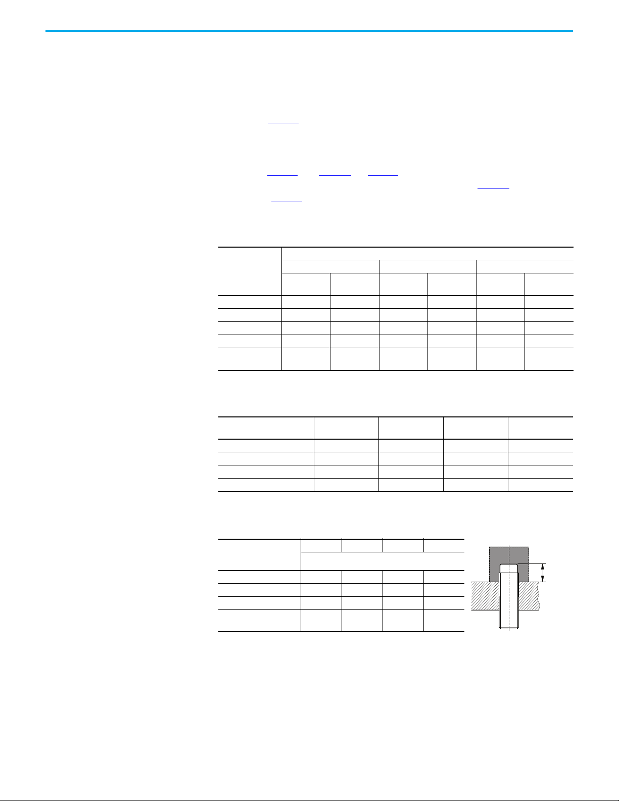
Correction Factors To determine the sensing distance for materials other than the standard mild
steel, a correction factor is used. The correction factors are used as a general
guideline for determining the de-rated sensing distance, if applicable.
Instructions for unshielded sensor: To determine the appropriate correction
factor, use Table 1
sensing range to determine de-rated sensing distance, if applicable.
Instructions for shielded sensor: To determine the appropriate correction
factor, use Table 1
factor based on the type and the target material. Then, in Table 2
result from Table 1
the final correction factor.
Table 1 - Correction Factor
. Multiply the sensor type with the target material by the
and Table 2. In Table 1, determine the appropriate correction
, multiply the
by the material the sensor is mounted in. This number is
Target Material
(No Surrounding
Metal)
(Shielded)
Steel 111111
Copper 0.85 0.8 0.8 0.9 0.9 0.9
Aluminum111111
Brass 1.3 1.4 1.2 1.35 1.3 1.2
Stainless Steel
1 mm/2 mm thick
(1) No detection.
M12 M18 M30
6 mm
(Unshielded)
0.5/0.9
Barrel Size and Nominal Sensing Range
10 mm
(1)
/0.65
10 mm
(Shielded)
0.5/0.9 0.2/0.7 0.35/0.7
20 mm
(Unshielded)
20 mm
(Shielded)
40 mm
(Unshielded)
(1)
/0.25
Table 2 - Surrounding Material
Surrounding Material Type
Steel 1 0.7 0.75 0.9
Aluminum 0.9 1.15 0.9 0.7
Brass 0.9 1.05 0.75 0.6
Stainless Steel 1 0.8 0.8 1.3
8 mm Dia.,
Shielded
12 mm Dia.,
Shielded
18 mm Dia.,
Shielded
30 mm Dia.,
Shielded
The following table indicates the protrusion distance from the mounting
device for the unshielded sensor face.
Unshielded Sensor
Distance from Mounting
Device [mm (in.)]
Steel 15 (0.59) 22 (0.87) 36 (1.41) 18 (0.71)
Aluminum 9 (0.35) 13 (0.51) 22 (0.87) 34 (1.34)
Brass 10 (0.39) 15 (0.59) 22 (0.87) 34 (1.34)
8 mm Dia. 12 mm Dia. 18 mm Dia. 30 mm Dia.
Unshielded
See table
Stainless Steel 14 (0.55) 21 (0.83) 43 (1.69) 18 (0.71)
Rockwell Automation Publication 871TM-UM002D-EN-P - February 2021 11
Page 12

Chapter 1 Product Overview
Notes:
12 Rockwell Automation Publication 871TM-UM002D-EN-P - February 2021
Page 13
Installation
Chapter 2
User Interface
Mounting
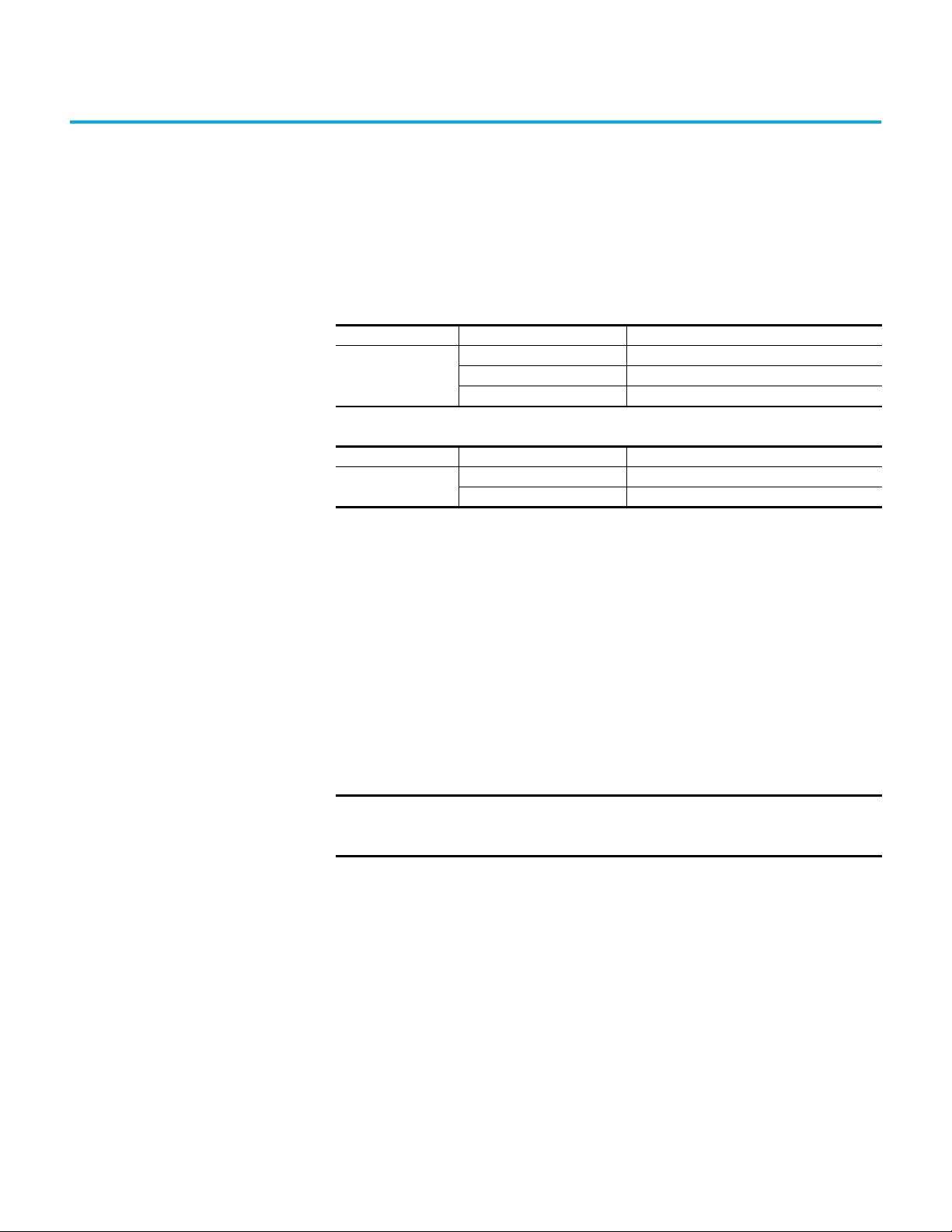
Table 3 - Standard I/O Operation
Status Indicator State Condition
OFF Output is OFF
Yel lo w
Blinking (margin indication) Target is 80…100% of the maximum sensing range
Table 4 - IO-Link Operation
Status Indicator Color State Condition
Yel low
Securely mount the sensor on a firm, stable surface, or support for reliable
operation. Mounting is subject to excessive vibration or shifting could cause
intermittent operation. Once securely mounted, the sensor can be wired per
the wiring instructions in the next section.
You may need to adjust the sensor in the mounting due to the location of the
target in relation to the sensor face. The 871TM sensor offers margin
indication through the yellow status indicator. The status indicator blinks
when the target is 80% of the maximum sensing distance or farther from the
sensor face. It is recommended that you adjust the sensor to be closer to the
target.
ON Sensor output is triggered ON
OFF Power is OFF
Solid Sensor is connected to IO-Link master
IMPORTANT
Rockwell Automation Publication 871TM-UM002D-EN-P - February 2021 13
When the sensor is connected to IO-Link, the status indicators do not
indicate margin status. The margin status is shown as a process bit in
the Studio 5000® controller tag.
Page 14
Chapter 2 Installation
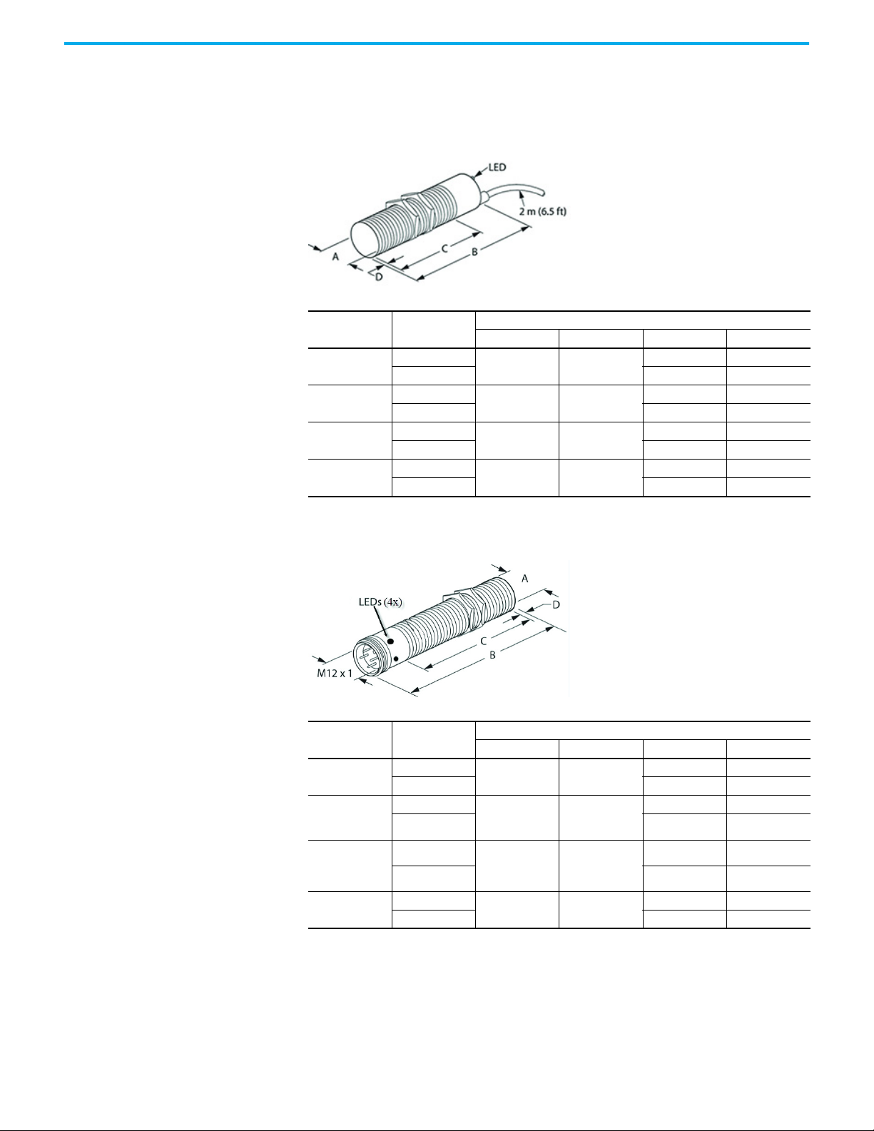
Dimensions The following illustrations show the relevant device dimensions.
Cable Style
Thread Size Shielded
M8 x 1
M12 x 1
M18 x 1
M30 x 1.5
Micro QD Style
Thread Size Shielded
M8 x 1
M12 x 1
[mm (in.)]
ABCD
Yes
No — 4 (0.16)
Yes
No 45 (1.77) 5 (0.19)
Yes
No 43 (1.69) 7 (0.27)
Yes
No 40 (1.57) 10 (0.39)
Yes
No 46 (1.81) 4 (0.16)
Yes
No 36 (1.42) 5 (0.19)
8 (0.31) 45 (1.77)
12 (0.47) 50 (1.96)
18 (0.71) 50 (1.96)
30 (1.18) 50 (1.96)
[mm (in.)]
ABCD
8 (0.31) 66 (2.60)
12 (0.47) 60 (2.36)
——
50 (1.96) —
50 (1.96) —
50 (1.96) —
46 (1.81) —
41 (1.61) —
M18 x 1
M30 x 1.5
14 Rockwell Automation Publication 871TM-UM002D-EN-P - February 2021
Yes
No 35.5 (1.40) 7 (0.27)
Yes
No 32.5 (1.28) 10 (0.39)
18 (0.71) 63.5 (2.5)
30 (1.18) 66.3 (2.61)
42.5 (1.67) —
42.5 (1.67) —
Page 15
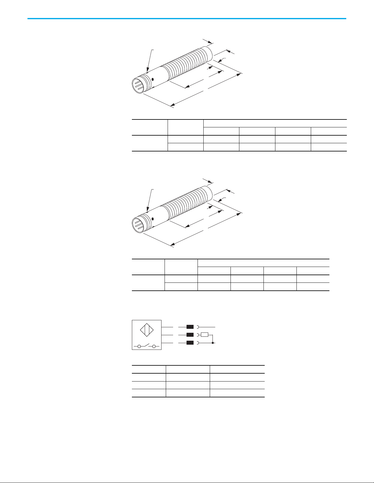
Pico QD Style — 3-pin
Brown
Black
Blue
1
4
3
+
DC
-
(Cable N.O. source)
Chapter 2 Installation
4 Status
Indicators
Thread Size Shielded
M8 x 1
Yes 8 (0.31) 60 (2.36) 51.5 (2.03) —
No 8 (0.31) 60 (2.36) 51.5 (2.03) 4 (0.16)
Pico QD Style — 4-pin
4 Status
Indicators
A
D
C
B
[mm (in.)]
ABCD
A
D
C
Wiring
B
Thread Size Shielded
M8 x 1
Yes 8 (0.31) 66 (2.59) 51.5 (2.03) —
No 8 (0.31) 66 (2.59) 51.5 (2.03) 4 (0.16)
ABCD
[mm (in.)]
Pin Signal Description
1 10…30V DC Device supply
3GNDGND for device
4 LOAD IO-Link/Output/SIO
We recommend the use of Bulletin 889 cordsets and patchcords for quickdisconnect (QD) model sensors. All external wiring must conform to the
National Electric Code and all applicable local codes.
Rockwell Automation Publication 871TM-UM002D-EN-P - February 2021 15
Page 16

Chapter 2 Installation
Notes:
16 Rockwell Automation Publication 871TM-UM002D-EN-P - February 2021
Page 17

Chapter 3
871TM Long-range Sensor with IO-Link Overview
What Is IO-Link? IO-Link technology is an open point-to-point communication standard and
was launched as (IS) IEC 61131-9. IO-Link is now the first globally standardized
technology for sensor and actuator communication with a field bus system.
This technology provides benefits to both OEMs and end users.
IO-Link provides communications-capable sensors to the control level by a
cost-effective point-to-point connection. IO-Link provides a point-to-point
link between the I/O module and sensor that is used for transferring detailed
diagnostics, device identity information, process data, and parameterization.
IO-Link communication is based on a master-slave structure in which the
master controls the interface access to the sensor. The option of using the
intelligence that is integrated into the sensor provides you with new methods
to commission your sensor. Benefits range from reduced installation time
during startup to increased diagnostics over the lifetime of the machine.
Benefits of IO-Link technology include:
• Reduced inventory and operating costs
• Increased uptime/productivity
• Simplified design, installation, configuration, and maintenance
• Enhanced flexibility and scalability
• Detailed diagnostic information for preventative maintenance
Why IO-Link? IO-Link offers a full range of advanced features and functions.
Seamless Integration
• Forward and backward compatible, sensor catalog numbers remain the
same
• No special cables required
• Connectivity options remain the same
• Access IO-Link functionality by simply connecting an IO-Link enabled
device to an IO-Link master
Real-time Diagnostics and Trending
• Real-time monitoring of the entire machine down to the sensor level
• Optimized preventative maintenance—identify and correct issues
before failures can occur
• Detect sensor malfunctions/failure
Rockwell Automation Publication 871TM-UM002D-EN-P - February 2021 17
Page 18
Chapter 3 871TM Long-range Sensor with IO-Link Overview
Sensor Health Status
Real-time monitoring verifies that sensors are operating correctly
Device Profiles and Automatic Device Configuration
• Golden device configurations are stored in the IO-Link master module
• Within minutes instead of hours, modify sensor parameters to produce
different finished goods
Descriptive Tags
• Faster programming during initial setup
• More efficient troubleshooting process data tags are named based on the
information they provide
• Easily monitor sensor data though intuitive tag names
How Does IO-Link Work? IO-Link delivers data over the same standard field cabling used today. By
connecting an IO-Link sensor to an IO-Link master, the field-device data and
diagnostics are accessible. So, go beyond product detection on the machine—
now the health of the machine can be monitored as it runs.
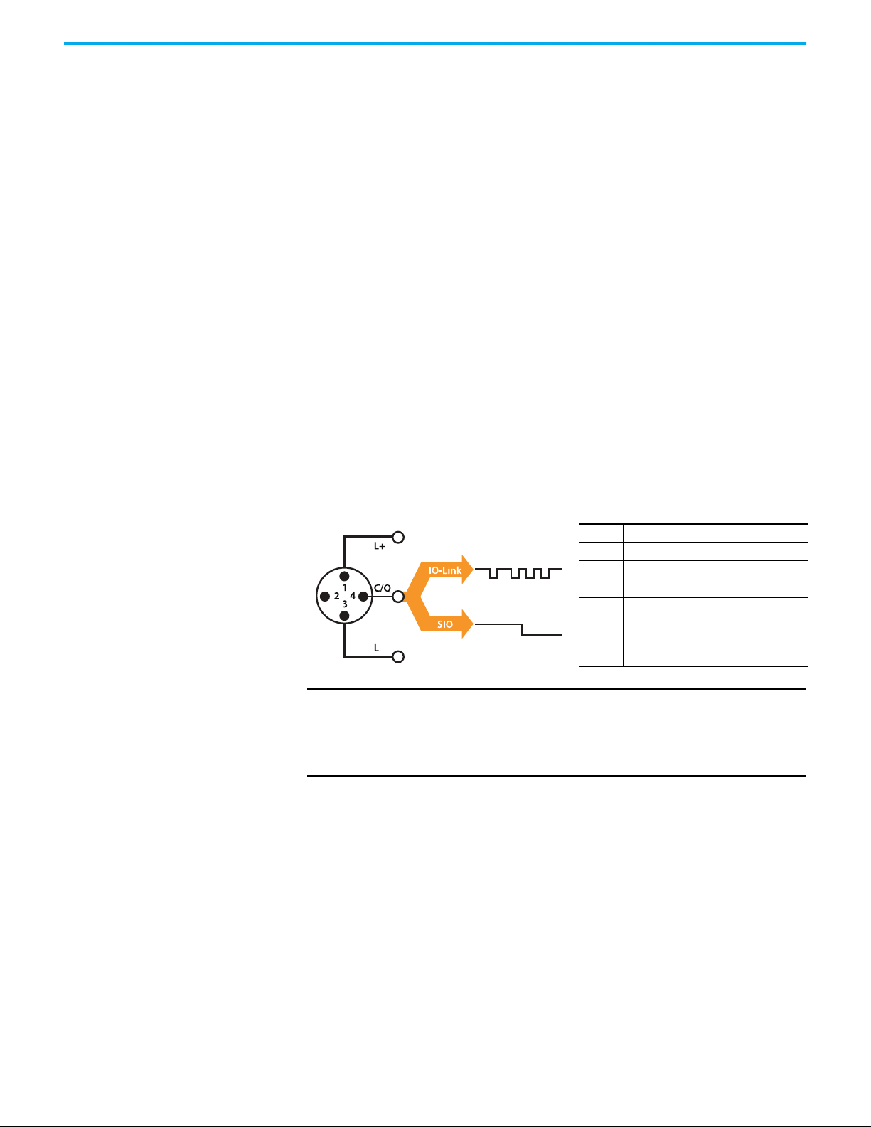
Pin Signal Remark
1L+ 24V
2 Out Depends on sensor
3L- Ground
4C/Q
Communication/
switching signal
IMPORTANT The response time of an IO-Link system may not be fast enough for
high-speed applications. In this case, it may be possible to monitor/
configure the sensor through IO-Link on pin 4 of the sensor while
connecting pin 2 (if the sensor offers a second output) of the sensor to
a standard input card.
Transmission Rates
Three communication rates are specified for the IO-Link device:
•COM 1 = 4.8 kBd
•COM 2 = 38.4 kBd
• COM 3 = 230.4 kBd
An IO-Link device typically supports only one of the specified transmissions
rates, while the IO-Link V1.1 specifications requires an IO-Link master to
support all three communication rates. (See Specifications on page 10
communication rates.)
18 Rockwell Automation Publication 871TM-UM002D-EN-P - February 2021
for
Page 19

Chapter 3 871TM Long-range Sensor with IO-Link Overview
Transmission Quality
The IO-Link communication system operates at a 24V level. If a transmission
fails, the frame is repeated two more times. If the transmission fails on the
second try, the IO-Link master recognizes a communication failure and
signals it to the controller.
Response Time of the IO-Link System
The device description file (IODD) of the device contains a value for the
minimum cycle time of the device. This value indicates the time intervals at
which the master may address the device. The value has a large influence on
the response time. In addition, the master has an internal processing time that
is included in the calculation of the system response time.
Devices with different minimum cycle times can be configured on one master.
The response time differs accordingly for these devices. When configuring the
master, you can specify a fixed cycle time and the device-specific minimum
cycle time that is stored in the IODD. The master then addresses the device
that is based on this specification. The typical response time for a device
therefore results from the effective cycle time of the device and the typical
internal processing time of the master. (See Specifications on page 10
minimum cycle time.)
for
IO-Link Data Types There are four data types available through IO-Link:
Process data → Cyclic data
Value status → Cyclic data
Device data → Acyclic data
Events → Acyclic data
Process Data
The process data of the devices are transmitted cyclically in a data frame in
which the device specifies the size of the process data. Depending on the
device, 0…32 bytes of process data are possible (for each input and output). The
consistency width of the transmission is not fixed and is thus dependent on
the master.
Some devices can support multiple process data modes, which allow you to
select different cyclic process data themes.
Value Status
The value status indicates whether the process data is valid or invalid. The
value status can be transmitted cyclically with the process data.
Rockwell Automation Publication 871TM-UM002D-EN-P - February 2021 19
Page 20

Chapter 3 871TM Long-range Sensor with IO-Link Overview
Device Data
Device data supports device-specific configurable parameters, identification
data, and diagnostic information. They are exchanged acyclically and at the
request of the IO-Link master. Device data can be written to the device (Write)
and also read from the device (Read).
Events
When an event occurs, the device signals the presence of the event to the
master. The master then reads out the event. Events can be error messages and
warnings/maintenance data. Error messages are transmitted from the device
to the controller via the IO-Link master. The transmission of device
parameters or events occurs independently from the cyclic transmission of
process data (see Appendix C on page 79
associated codes).
for device-specific events and
Access IO-Link Data Cyclic Data
To exchange the cyclic process data between an IO-Link device and a
controller, the IO-Link data from the IO-Link master is placed on the address
ranges assigned beforehand. The user program on the controller accesses the
process values using these addresses and processes them. The cyclic data
exchange from the controller to the IO-Link device (that is, IO-Link sensor) is
performed in reverse.
Acyclic Data
Acyclic data, such as device parameters or events, are exchanged using a
specified index and subindex range. The controller accesses these using
Explicit Messaging. The use of the index and subindex ranges allows targeted
access to the device data (that is, for reassigning the device or master
parameters during operation).
Start-up the I/O System If the port of the master is set to IO-Link mode, the IO-Link master attempts to
communicate with the connected IO-Link device. To do so, the IO-Link master
sends a defined signal (wake up pulse) and waits for the IO-Link device to
reply.
The IO-Link master initially attempts to communicate at the highest defined
data transmission rate. If unsuccessful, the IO-Link master then attempts to
communicate at the next lower data transmission rate.
If the master receives a reply, the communication begins. Next, it exchanges
the communication parameters. If necessary, parameters that are saved in the
system are transmitted to the device. Then, the cyclic exchange of the process
data and value status begins.
20 Rockwell Automation Publication 871TM-UM002D-EN-P - February 2021
Page 21

Chapter 3 871TM Long-range Sensor with IO-Link Overview
Assign Device Parameters Configuration of a device for a specific application requires changes to
parameter settings. The device parameters and setting values are contained in
the IODD of the device.
I/O Device Description (IODD) files contain information about the device
identity, parameters, process data, diagnostic data, and communication
properties. These files are required to establish communication with the
sensors via IO-Link.
The IODD consists of multiple data files; the main file and several optional
language files are in XML-format and graphic files are in PNG format
(portable network graphics). These files adhere to the IO-Link open standard,
which means that they can be used with any IO-Link masters.
IODD files are assigned using the Studio 5000 environment and the 1734-4IOL
Add-on Profile (when using the 1734-4IOL IO-Link master module).
Rockwell Automation Solution
Rockwell Automation is the only supplier who provides every piece of the
Connected Enterprise solution from top to bottom. Plus, exclusive features
and Premier Integration between Allen-Bradley® components and an
Integrated Architecture® system allow for a seamless connection and
commission of control components. Empowering the ability to reap the
benefits of an IO-Link solution with access to more detailed and customized
plant-floor information than other solutions can offer.
Rockwell Automation Publication 871TM-UM002D-EN-P - February 2021 21
Page 22
Chapter 3 871TM Long-range Sensor with IO-Link Overview
Premier Integration The Studio 5000 Logix Designer® environment combines design and
engineering elements in one interface, which enables you to access I/O and
configuration data across the Integrated Architecture system. Use of a
Rockwell Automation solution, provides a smooth, consistent integration of
Allen-Bradley IO-Link enabled devices into the system.
To simplify the integration of the Allen-Bradley IO-Link devices to the
Rockwell Automation architecture, there is an IO-Link Add-on Profile (AOP)
available for the 1734-4IOL master module. The use of an AOP simplifies the
setup of devices by providing the necessary fields in an organized manner that
allows you to build and configure their systems in a quick and efficient
manner.
22 Rockwell Automation Publication 871TM-UM002D-EN-P - February 2021
Page 23
Chapter 3 871TM Long-range Sensor with IO-Link Overview
871TM Sensor IO-Link Features
The following features are available in the 871TM sensor:
Feat ure Des cript ion
Triggered
Polarity
Margin Status
Switching Timer Mode
The process data bit that communicates the change in state of the 871TM sensor upon the
detection of a target. The status of the triggered bit can be viewed in a Studio 5000
controller tag.
Changes the operation of the triggered parameter. It performs the same function as
normally open or normally closed in standard I/O (SIO) mode.
The process data bit that communicates the target is within or beyond 80% of the
maximum sensing range of the sensor. The margin status bit can be viewed in Studio
5000 controller tag.
Ability to manipulate the output of the sensor in relation to timing. It is useful for precision
applications where the output of the needs to be precisely triggered at a certain time.
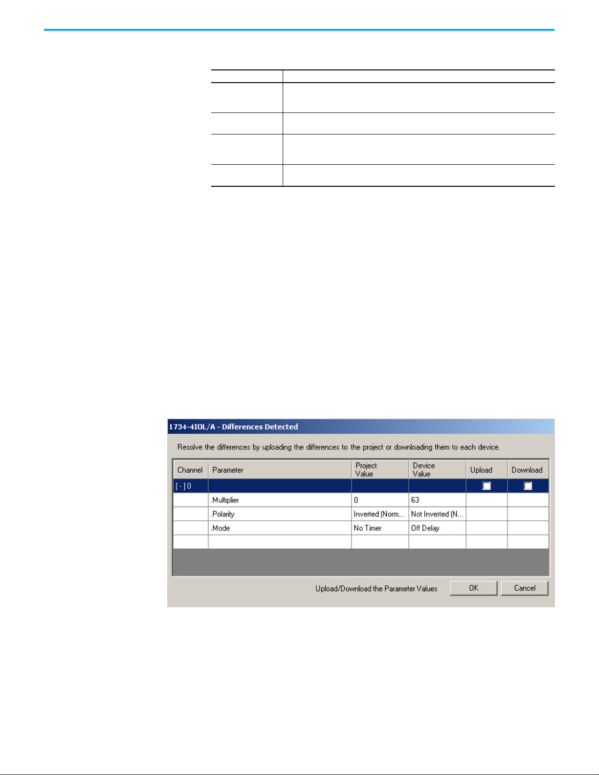
Correlation
The AOP reads all configuration read-write (R.W.) parameters directly from the
connected IO-Link devices and compares the values to ones stored in the
controller. This action determines if there are differences (note that the
correlation does not work for read-only (R.O.) in the parameters or for
competitive sensors.). This feature is for Allen-Bradley enabled IO-Link devices
only and is an online only function that runs when opening up the AOP.
• No differences: There are no differences, so you go directly into the AOP.
• Differences: If there are differences, the user is provided with a
differences dialogue that identifies the IO-Link parameters that, do not
match for each channel. You can then choose, on a channel by channel
basis (where differences exist) to upload the parameters that are currently
in the device and store them in the controller. Alternatively, you can
choose to download the parameters that are stored in the controller to the
connected IO-Link device.
Rockwell Automation Publication 871TM-UM002D-EN-P - February 2021 23
Page 24
Chapter 3 871TM Long-range Sensor with IO-Link Overview
Automatic Device Configuration (ADC)
Replacement of damaged sensors is easy. Simply remove the old Allen-Bradley
sensor and connect the new sensor (with the same catalog number) — the
controller automatically sends the configuration to the new sensor.
ADC capability within the sensor and controller enable flexibility and reliability
in your application. When the sensor becomes damaged or fails and must be
replaced, replace it with the exact same catalog number of the existing sensor.
When the damaged sensor is removed and the new sensor is plugged in, the
existing
Link Master. No additional steps are required on the sensor or in the controller.
No personal computer is required and reteaching the sensor is not required.
configuration
is automatically stored in the sensor through the IO-
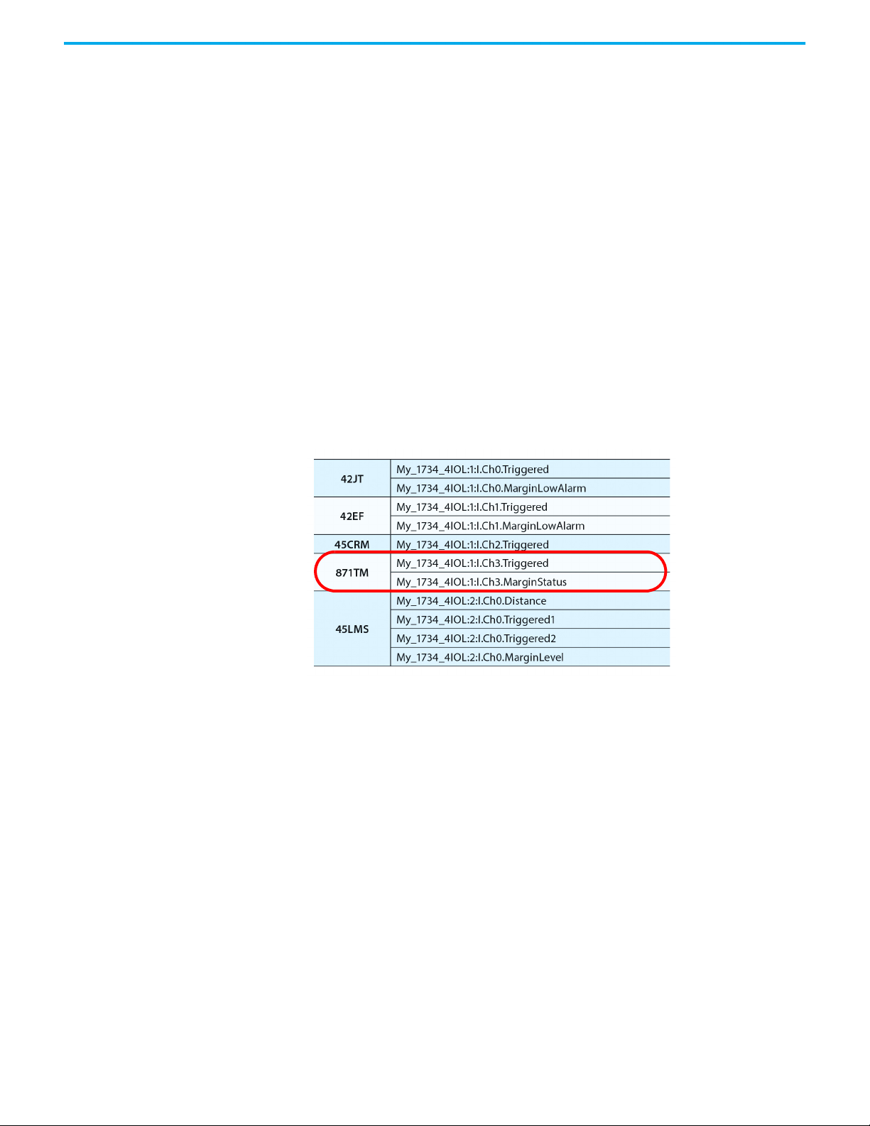
Tag Naming for I/O Data
Rockwell Automation system solutions provide tag names that are based on
the Allen-Bradley sensor connected. I/O data is converted, formatted, and
named based on the Allen-Bradley sensor applied. Reduces commissioning
time by the OEM and reduces troubleshooting time by the end user when
searching for sensor data. Consistent naming techniques used.
The Triggered and Margin Status that is previously shown are examples of
consistent tag names that are used across all Allen-Bradley sensors. These tags
give insightful and descriptive meaning to the operation of the sensor output.
The tags may change depending on the type of sensor being used and the
functionality within the sensor.
24 Rockwell Automation Publication 871TM-UM002D-EN-P - February 2021
Page 25

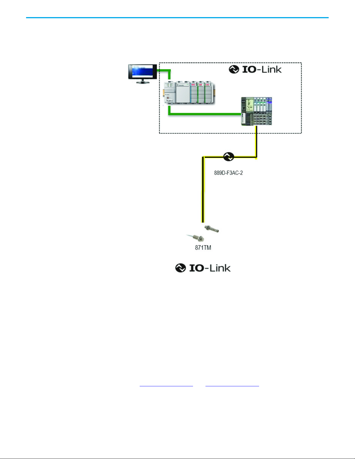
Chapter 4
Configure the 871TM Sensor for IO-Link Mode
This chapter shows the physical hardware and software that is required to
configure the 871TM sensor through IO-Link and provides a simple guide to
setting up the hardware.
The products that are required include the following hardware and software.
Hardware •871TM-xx (compatible sensors are N.O. PNP) with 12 mm or 18 mm barrel
diameter
• CompactLogix™ or ControlLogix® PLC Platform
• POINT I/O™ Communications Interface: 1734-AENTR
• POINT I/O IO-Link Master Module: 1734-4IOL
•POINT I/O Terminal Base: 1734-TB
• RJ45 network cable for EtherNet/IP™ connectivity:
1585J-M8TBJM-1M9xx
• 889D cordsets (optional): 889D-F3AC-2xx (IO-Link maximum acceptable
cable length is 20 m [65.6 ft])
Software • Studio 5000® environment, version 20 and higher
• Sensor-specific IODD
• 1734-4IOL IO-Link Add-on Profile (AOP)
Rockwell Automation Publication 871TM-UM002D-EN-P - February 2021 25
Page 26
Chapter 4 Configure the 871TM Sensor for IO-Link Mode
Example: Set up the Hardware
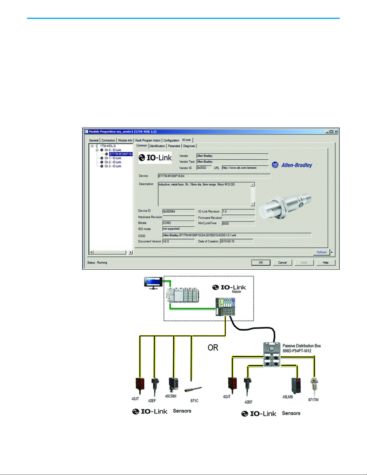
In this example, a POINT I/O™ chassis is shown with a 1734-AENTR adapter
and a 1734-4IOL IO-Link master module in the first slot. The 1734-AENTR
adapter is communicating with a CompactLogix controller via an EtherNet/IP
network.
When adding a 871TM sensor to the 1734-4IOL master module, complete the
following steps:
1. Provide power to the 1734-AENTR adapter.
2. Set the node address on 1734-AENTR adapter.
3. Connect the 1734-AENTR adapter to the Allen-Bradley controller with the
recommended RJ45 Ethernet cable.
4. Wire the sensor cable to the desired location on the IO-Link master (in
this example, we are showing the sensor that is wired to the channel 0).
5. Connect the 871TM sensor to the other end of the sensor cable.
6. After connecting the sensor, you must create/open a project in the Studio
5000 environment to establish communication with the Allen-Bradley
controller that is being used. You must also add the 1734-AENTR adapter
and 1734-4IOL IO-Link master module to Controller Organizer Tree (see
Chapter 6 on page 31
26 Rockwell Automation Publication 871TM-UM002D-EN-P - February 2021
and Chapter 7 on page 35 for detailed instructions).
Page 27

Chapter 5
Create a Project
Project Creation To begin a new Studio 5000® project, follow the steps in this chapter.
If there is an existing project within the Studio 5000 environment with
CompactLogix™ or ControlLogix® hardware that is installed and
communicating online, go directly to Chapter 6 on page 31
1. Double-click the Studio 5000 environment icon.
2. Click New Project.
.
3. In the New Project dialog box, select the controller for your project, name
the project, and click Next.
In this example, the project is named 1769 L24ER CompactLogix 5370
controller.
Rockwell Automation Publication 871TM-UM002D-EN-P - February 2021 27
Page 28

Chapter 5 Create a Project
4. After selecting the controller, name the project and click Next.
In this example, the project name is “Project871TM.”
5. To verify communication, set the IP address by clicking the browsing
icon.
Project871TM opens.
28 Rockwell Automation Publication 871TM-UM002D-EN-P - February 2021
Page 29

Chapter 5 Create a Project
6. Select the controller that is being used for the project and click Go Online
to start communication.
In this example, we are using a 1769-L24ER-QB1B CompactLogix.
The next step is to Configure the IO-Link Master on page 31
.
Rockwell Automation Publication 871TM-UM002D-EN-P - February 2021 29
Page 30

Chapter 5 Create a Project
Notes:
30 Rockwell Automation Publication 871TM-UM002D-EN-P - February 2021
Page 31

Chapter 6
Configure the IO-Link Master
Configuration Procedure 1. Make sure that the controller is offline to configure the IO-Link Master.
2. In the controller organizer tree, find Ethernet under I/O Configuration
and right-click to add New Module.
The module window pops up and shows the available modules.
Rockwell Automation Publication 871TM-UM002D-EN-P - February 2021 31
Page 32

Chapter 6 Configure the IO-Link Master
3. Select the “1734-AENTR, 1734 Ethernet adapter, 2-port, twisted-pair
media” and click Create.
4. Name the Ethernet adapter (in this example our adapter name is
“adapter”), set the chassis size, check the module revision, and configure
the adapter Ethernet address. Click OK and then Close.
32 Rockwell Automation Publication 871TM-UM002D-EN-P - February 2021
Page 33

Chapter 6 Configure the IO-Link Master
5. The 1734-AENTR adapter appears in the Controller Organizer tree.
6. Right-click the 1734-AENTR/B Adapter, and click New Module.
Rockwell Automation Publication 871TM-UM002D-EN-P - February 2021 33
Page 34

Chapter 6 Configure the IO-Link Master
7. Select “1734 IO-Link Module Profiles” and click Install.
The IO-Link Configuration screen appears.
8. Name the IO-Link Master and click OK.
The 871TM sensor can now be configured. To configure the sensor, a sensorspecific IODD (I/O Device Description) file is required. The next steps show
how to register the IODD file.
AOP Installation Verify that the Studio 5000® environment contains the 1734-4IOL IO-Link AOP.
Version 20 or higher of Studio 5000 environment supports this module and
AOP. To verify that the 1734-4IOL module is installed, verify that the 1734AENTR adapter contains the 1734-4IOL in the library. If the AOP is required to
be downloaded, see Appendix A on page 71
34 Rockwell Automation Publication 871TM-UM002D-EN-P - February 2021
for more information.
Page 35

Chapter 7
Connect the 871TM to the IO-Link Master
Connection Procedure Once the IO-Link master is configured, connect the sensor to the IO-Link
master. Take the controller offline to add a device to the IO-Link master.
1. Go to the IO-Link tab and click Change.
2. Choose the IO-Link channel number that you want to add a sensor to and
click the Change Device column.
A window that contains a library of all sensors that are currently
registered in the IO-Link Device Library appears.
Rockwell Automation Publication 871TM-UM002D-EN-P - February 2021 35
Page 36

Chapter 7 Connect the 871TM to the IO-Link Master
3. Select the appropriate sensor and click Create.
If the sensor does not appear in the library, see Chapter 8 on page 41
learn how to Register the IODD.
to
The sensor is now in the channel configuration window.
36 Rockwell Automation Publication 871TM-UM002D-EN-P - February 2021
Page 37

Chapter 7 Connect the 871TM to the IO-Link Master
4. You can change the Application Specific Name, Electronic Keying, and
Process Data Input configuration while the project is in the offline mode.
IMPORTANT
The 871TM IO-Link does not support Application Specific Name or
Process Data Input configuration.
Modify the information:
• Application Specific Name (ASN): The purpose of the Application
Specific Name is to add theme naming to distinguish the sensors
within a machine and the associated project profile in the Add-on
Profile (AOP). The ASN allows for easier maintenance and operation
since the device is further identified by how it is used on the machine/
project.
• Electronic Keying Information: Select Exact Match or Disabled from
the pull-down menu. The Exact Match and Disabled keying options in
this dialog correspond to the Compatible and No Check keying options
in IO-Link terminology, respectively.
When Exact Match is selected, the connected IO-Link device must
have the same Vendor ID, Device ID, and Revision information that
has been configured for that channel. If they do not match, IO-Link
communications are not established and a Keying Fault status bit is
set. When Disabled is selected, key check is not performed.
• Process Data Input: Select the input data from the pull-down menu
(for devices that support multiple layouts of input data).
Click OK.
5. Click Yes to confirm the sensor changes.
The module properties screen appears on the General Tab.
Rockwell Automation Publication 871TM-UM002D-EN-P - February 2021 37
Page 38

Chapter 7 Connect the 871TM to the IO-Link Master
6. Click the IO-Link tab.
7. Locate the sensor that you added in the organization tree and select it.
The sensor can now be configured through the AOP.
38 Rockwell Automation Publication 871TM-UM002D-EN-P - February 2021
Page 39

Chapter 7 Connect the 871TM to the IO-Link Master
8. Click Go Online to communicate with the controller and sensor.
Proceed to Chapter 9 on page 49
for a description of each tab that is associated
with the 1734 AOP and a description of how the AOP can be used to configure
the sensor.
Rockwell Automation Publication 871TM-UM002D-EN-P - February 2021 39
Page 40

Chapter 7 Connect the 871TM to the IO-Link Master
Notes:
40 Rockwell Automation Publication 871TM-UM002D-EN-P - February 2021
Page 41

Chapter 8
Register the 871TM IODD
If you are not able to locate the 871TM in the IO-Link Sensor Library (as shown
in the previous chapter), then you must register the IODD of the sensor. By
default, the IODDs are already located in the Add-on Profile (AOP), but as new
products are released it is necessary to add products to the library.
The I/O Device Description (IODD) files contain the information that is related
to the sensor, integrated into the system environment. To initialize a sensor on
an IO-Link Master, you must register the IODD of the sensor.
If the IODD file for the sensor cannot be located in the library, it can be
downloaded from rok.auto/pcdc
to register the IODD again unless it is manually deleted from the Master Tree.
. Once the IODD is registered, there is no need
Registration Procedure 1. Double-click 1734-4IOL in the Controller Organizer Tree.
2. Click the IO-Link tab.
Rockwell Automation Publication 871TM-UM002D-EN-P - February 2021 41
Page 42

Chapter 8 Register the 871TM IODD
3. On the IO-Link screen, click Change.
4. Click in the Change Device column for the IO-Link channel number that
the sensor is added to.
5. In the IO-Link Device Library window, click Register IODD.
42 Rockwell Automation Publication 871TM-UM002D-EN-P - February 2021
Page 43

Chapter 8 Register the 871TM IODD
6. Click Register IODD in the following dialog box.
7. Locate the IODD XML file and double-click it. Then, click Open.
Rockwell Automation Publication 871TM-UM002D-EN-P - February 2021 43
Page 44

Chapter 8 Register the 871TM IODD
8. Click Exit.
The 871TM is now visible in the IO-Link Device Library.
44 Rockwell Automation Publication 871TM-UM002D-EN-P - February 2021
Page 45

Chapter 8 Register the 871TM IODD
9. Select the appropriate sensor and click Create.
10. Verify that the sensor appears in the channel configuration window and
click OK.
You can change the Application Specific Name, Electronic Keying, and
Process Data Input configuration while the project is in the offline mode.
IMPORTANT
The 871TM IO-Link does not support Application Specific Name or
Process Data Input configuration.
Modify the information:
• Application Specific Name (ASN): The purpose of the Application
Specific Name is to add theme naming to distinguish the sensors
within a machine and the associated project profile in the AOP. The
ASN allows for easier maintenance and operation since the device is
further identified by how it is used on the machine/project.
Rockwell Automation Publication 871TM-UM002D-EN-P - February 2021 45
Page 46

Chapter 8 Register the 871TM IODD
• Electronic Keying Information: Select Exact Match or Disabled from
the pull-down menu. The Exact Match and Disabled keying options in
this dialog correspond to the Compatible and No Check keying options
in IO-Link terminology, respectively.
When Exact Match is selected, the connected IO-Link device must
have the same Vendor ID, Device ID, and Revision information that
has been configured for that channel. If they do not match, IO-Link
communications is not established and a Keying Fault status bit is set.
When Disabled is selected, key check is not performed.
• Process Data Input: Select the input data from the pull-down menu
(for devices that support multiple layouts of input data).
Click OK.
11. Click Yes to confirm the sensor changes.
The module properties screen appears on the General Tab.
12. Click the IO-Link tab and navigate to the sensor that was added. The
sensor can now be programmed through the AOP.
46 Rockwell Automation Publication 871TM-UM002D-EN-P - February 2021
Page 47

Chapter 8 Register the 871TM IODD
13. Click Go Online to communicate with the controller and sensor.
The IODD registration and connection to the IO-Link master is complete.
Proceed to Chapter 9 on page 49
for a description of each tab that is associated
with the 1734 AOP and a description of how the AOP is used to configure the
sensor.
Rockwell Automation Publication 871TM-UM002D-EN-P - February 2021 47
Page 48

Chapter 8 Register the 871TM IODD
Notes:
48 Rockwell Automation Publication 871TM-UM002D-EN-P - February 2021
Page 49

Review the 1734-4IOL IO-Link Add-on Profile
Overview Device Parameter Behavior
IO-Link parameters are shown in the Add-on Profile (AOP) only for IO-Link
devices with IODD Advanced integration. Each parameter can have an
attribute of read-only (ro), read-write (rw), or write only (wo). The behavior of
parameters and the source for their values differ whether you are offline or
online.
Table 5 - IO-Link Device Parameter Behavior
Attribute Offline Online
Read-only (ro) Parameters are blank. Parameter values are read from the connected IO-Link device.
Read-write (r w) Parameter values are read from the IODD file
when the IO-Link device is added.
Changes made to the parameters are
applied when the OK and Apply buttons are
clicked.
Write only (wo) Parameter buttons are disabled. Parameter buttons that could potentially alter the Process Data
Chapter 9
Parameters show “??” when communication breaks.
Parameter values can be edited and changes made to the
parameters are applied when the OK and Apply buttons are
clicked.
Changes are sent to the Master Module, which then writes the
changes to the connected IO-Link device.
are disabled.
Other parameter buttons that are enabled, result in commands
being sent to the connected IO-Link device.
The 1734-4IOL AOP offers four different tabs to describe the sensor
functionality and operation. These tabs are:
• Common Tab: General product information about the sensor
specifications and IO-link IODD information.
• Identification Tab: Sensor cat. no., series letter, general product
description including the current product firmware, and hardware
revisions.
• Parameter Tab: Different configurable parameters available in the
871TM.
• Diagnosis Tab: Monitor IO-Link communication characteristics.
For a complete listing of all sensor parameters and parameter definitions, see
Device Parameters on page 77
.
Rockwell Automation Publication 871TM-UM002D-EN-P - February 2021 49
Page 50

Chapter 9 Review the 1734-4IOL IO-Link Add-on Profile
Common Tab The common tab is automatically generated to give general information about
the sensor. The tab contains:
•
Vendor
•
Vendor ID
•
URL
• Device and
•Device
•IO-Link
• Hardware and Firmware Revision
•
Bitrate
•MinCycle
•
IODD
•Document
•Date of
Description
ID
Revision
Time
Version
creation
50 Rockwell Automation Publication 871TM-UM002D-EN-P - February 2021
Page 51

Chapter 9 Review the 1734-4IOL IO-Link Add-on Profile
Identification Tab The Identification tab shows device information such as specific Vendor ID
and Device ID for the exact sensor that is configured. These fields are
automatically populated according to the sensor information. These fields are
Read Only (ro).
Parameter Tab
The Parameter tab allows changes to the behavior of the output of the sensor.
The IO-Link master uses these parameters for validation purposes.
Rockwell Automation Publication 871TM-UM002D-EN-P - February 2021 51
Page 52

Chapter 9 Review the 1734-4IOL IO-Link Add-on Profile
Polarity
The 871TM sensor features the ability to change the output switching mode.
The factory default mode is Not Inverted (normally open). With the sensor in
IO-Link mode, you can change the polarity parameter to Inverted (normally
closed). The sensor cannot operate in Inverted (normally closed) mode while
operating in IO-Link mode. Therefore, to use the Inverted (normally closed)
functionality, the sensor must be disconnected from IO-Link and used as a
standard input/output (SIO) device.
If you want to change the sensor back to “Not Inverted” (normally open), you
must connect the sensor back to the IO-Link master and change the setting
under the polarity parameter.
Switching Timer Mode
The switching timer is a useful function for manipulating the output of the
sensor in relation to timing. It is useful for precision applications where the
output of the sensor must be precisely triggered at a certain time. It is
important to note that the lowest time base must be used and that there is a
tolerance error of approximately ±15%.
IMPORTANT The enable parameter must be ON to enable the switching timer mode.
The 871TM sensor uses a time base with an associated offset value along with a
multiplier to create a delay value when using the switching timer mode
function. It is important that the smallest time base and multiplier is used to
create the delay. By using the smallest time base and multiplier, the tolerance
error of ±15% can be reduced. An example is provided to understand the
relationship between the different input values. The maximum delay that can
be entered is 537.6 ms.
Desired Time Delay= (Time Multiplier) (Time Base) + Offset Value
Time Base Offset Value (ms) Timer Multiplier (ms)
0 = 0.1 ms 0 0…63 ms
1 = 0.4 ms 6.4
2 = 1.6 ms 32
3 = 6.4 ms 134.4
For example: To achieve a delay of approximately24 milliseconds, you must use a time
base of 1 (0.4 ms) and 44 milliseconds for a timer base multiplier. This value does not
factor in the tolerance error of ±15%.
24 ms = (44) (0.4) + 6.4 ms
No Timer = sensor performs without any delays with the output before or after
the target in presented in front of the sensor
Off Delay = sensor triggered bit stays ON after the target is removed from the
face of the sensor. The time the output is triggered ON after the target is
removed as dictated by the time base set and the multiplier used.
52 Rockwell Automation Publication 871TM-UM002D-EN-P - February 2021
Page 53

Chapter 9 Review the 1734-4IOL IO-Link Add-on Profile
No Target
Present
Tar ge t
Present
O-Delay
Target not
Present
Triggered ON
24 ms
O Delay
Time
1
0
No Target
Present
On Delay Target
Present
Tar ge t
Present
Triggered ON
24 ms
On Delay
Time
1
0
For example: Using the example above, implement an off delay of 24 ms.
On Delay = target is presented in front of the sensor, sensor triggered bit stays
OFF until switching time base and the multiplier time period have elapsed.
Once that time frame has elapsed, the trigger bit turns ON.
For example: Using the example above, implement an On Delay of 24 ms.
On Delay and Off Delay = Target is presented in front of the sensor, sensor
triggered bit stays OFF until switching time base and the multiplier have
elapsed. Once that time frame has elapsed, the trigger bit turns ON as long as
target is present. The sensor triggered bit stays ON after the target is removed
from the face of the sensor. The time the output is triggered ON after the target
is removed as dictated by the time base set and the multiplier used.
Rockwell Automation Publication 871TM-UM002D-EN-P - February 2021 53
Page 54

Chapter 9 Review the 1734-4IOL IO-Link Add-on Profile
For example: Using the example above, implement an On Delay and Off Delay of 24ms.
On Delay and O Delay
No Target
Present
1
On Delay Target
Present
Tar ge t
Present
O Delay Target
not Present
Triggered ON
Diagnosis Tab
0
24 ms
24 ms
Time
The Diagnosis tab shows the user communication characteristics such as cycle
time and IO-Link Revision ID.
54 Rockwell Automation Publication 871TM-UM002D-EN-P - February 2021
Page 55

Chapter 9 Review the 1734-4IOL IO-Link Add-on Profile
Controller Tags The controller tags have two process data tags that show the status of the sensor
concerning the output and the margin status.
Triggered: This process bit turns toggles to (1) when the sensor detects the
target and to (0) when the sensor does not detect the target. The sensor
operates as normally open when connected to IO-Link regardless of whether it
is normally closed.
Margin Status: The bit can be used as a low margin warning indicator to detect
the target is beyond the recommended working range of the sensor. This
process bit toggles to High (1) when the sensor detects a target AND the target
is between 0…80% of the operating range of the sensor. The process bit toggles
to Low (0) when the sensor detects a target beyond 80% of the specified
operating range of the sensor.
The recommended working range of the sensor is less than 80% of the specified
or nominal sensing range. Operation within the working range of the sensor
helps sustain stable operation with typical environmental
and supply voltage fluctuations and differences due to the manufacturer
tolerances.
temperature,
load,
Rockwell Automation Publication 871TM-UM002D-EN-P - February 2021 55
Page 56

Chapter 9 Review the 1734-4IOL IO-Link Add-on Profile
Notes:
56 Rockwell Automation Publication 871TM-UM002D-EN-P - February 2021
Page 57

Chapter 10
Configure the Sensor with the Studio 5000
Environment
This chapter provides detailed instructions on the configuration of the 871TM
sensor using message instructions in the Studio 5000® environment. The
example code that is shown allows you to:
• Read the sensor configuration
• Set the time delay multiplier
Sample Code To download the sample code that is shown in this chapter, find the IO-Link
871TM Explicit Messaging Example from the Sample Code Library
(rockwellautomation.com/en-us/support/product/product-downloads/
application-code-library/sample-code.html) and follow these steps:
1. Save and Extract PROX_871_TM.L5X to a folder of your choice.
2. Within your Logix Studio program, right-click Main program and click
Import Routine.
3. Browse to the folder that contains the routine that is extracted in step 1
Select and click Import.
.
Rockwell Automation Publication 871TM-UM002D-EN-P - February 2021 57
Page 58

Chapter 10 Configure the Sensor with the Studio 5000 Environment
4. In Import Configuration window, click OK to accept the default settings.
5. From within the MainRoutine, create a rung of code that runs the
subroutine PROX_871_TM.
6. Open the 871_TM subroutine. On rung 0 within the MSG instruction,
click the square button to open the message configuration.
58 Rockwell Automation Publication 871TM-UM002D-EN-P - February 2021
Page 59

Chapter 10 Configure the Sensor with the Studio 5000 Environment
7. In the Message configuration window, click the Communication Tab and
then click Browse.
8. Browse the Ethernet network to the 1734-AENTR/B adapter and select the
1734-4IOL Master. Click OK.
Rockwell Automation Publication 871TM-UM002D-EN-P - February 2021 59
Page 60

Chapter 10 Configure the Sensor with the Studio 5000 Environment
Notice that the path is now set to My_4IOL in the communication path.
Click Apply and then click OK.
9. Repeat step 8
for the Message instructions on rung 12 (Write_Index_1).
10. Verify that the routine is free of Errors.
11. Press Download to download the Program to the controller.
60 Rockwell Automation Publication 871TM-UM002D-EN-P - February 2021
Page 61

Chapter 10 Configure the Sensor with the Studio 5000 Environment
12. Click Yes to put the Controller back to Run mode.
Operation
The 871TM sensor conforms to V1.0 of the IO-Link standard. The parameters of
the sensor are defined in Index 1. Index 1 consists of 128 bits of data. Data
starts at an offset of 80 bits. When using explicit messages to read and change
the sensor, configuration of the whole index must be read/written to.
Open the Controller Tag viewer and locate the tag that is named
Sensor_Channel. Set this tag to equal the channel number the 871TM sensor is
connected to on the 1734-4IOL module.
Read the 871TM Configuration Via Explicit Message
Toggle the Read_Index contact on rung 1. This action runs the Message
instruction to read the data that is contained in Index 1.
Select the contact and press Ctrl-T to toggle contacts.
Rockwell Automation Publication 871TM-UM002D-EN-P - February 2021 61
Page 62

Chapter 10 Configure the Sensor with the Studio 5000 Environment
The sensor configuration is read back into the Read_Assembly array. Open the
controller tags from within the controller organizer. Expand the
Read_Assembly array. The configuration is detailed in Read_Assembly[4] and
[5].
Decipher the Data
Read_Assembly[4] Contains the Hex equivalent of the time delay in
milliseconds. Use Table 6
to convert the value to milliseconds.
Table 6 - Hex Value Conversion
Delay
Value
Hex
Value
(ms)
0 0 2.6 1A 5.2 4D 12 5E 22.4 8E 54.4 A2 96 CF 243.2 E6
0.1 01 2.7 1B 5.3 35 12.4 5F 22.8 79 56 A3 97.6 BD 249.6 E7
0.2 02 2.8 47 5.4 36 12.8 C2 23.2 7A 57.6 C9 99.2 BE 256 E8
0.3 03 2.9 1D 5.5 37 13.2 61 23.6 7B 59.2 A5 100.8 BF 262.4 E9
0.4 41 3 1E 5.6 4E 13.6 62 24 8F 60.8 A6 102.4 D0 268.8 EA
0.5 05 3.1 1F 5.7 39 14 63 24.4 7D 62.4 A7 108.8 D1 275.2 EB
0.6 06 3.2 82 5.8 3A 14.4 89 24.8 7E 64 CA 115.2 D2 281.6 EC
0.7 07 3.3 21 5.9 3B 14.8 65 25.2 7F 65.6 A9 121.6 D3 288 ED
0.8 42 3.4 22 6 4F 15.2 66 25.6 C4 67.2 AA 128 D4 294.4 EE
0.9 09 3.5 23 6.1 3D 15.6 67 27.2 91 68.8 AB 134.4 D5 300.8 EF
1 0A 3.6 49 6.2 3E 16 8A 28.8 92 70.4 CB 140.8 D6 307.2 F0
1.1 0B 3.7 25 6.3 3F 16.4 69 30.4 93 72 AD 147.2 D7 313.6 F1
1.2 43 3.8 26 6.4 C1 16.8 6A 32 C5 73.6 AE 153.6 D8 320 F2
1.3 0D 3.9 27 6.8 51 17.2 6B 33.6 95 75.2 AF 160 D9 326.4 F3
1.4 0E 4 4A 7.2 52 17.6 8B 35.2 96 76.8 CC 166.4 DA 332.8 F4
1.5 0F 4.1 29 7.6 53 18 6D 36.8 97 78.4 B1 172.8 DB 339.2 F5
1.6 81 4.2 2A 8 85 18.4 6E 38.4 C6 80 B2 179.2 DC 345.6 F6
1.7 11 4.3 2B 8.4 55 18.8 6F 40 99 81.6 B3 185.6 DD 352 F7
1.8 12 4.4 4B 8.8 56 19.2 C3 41.6 9A 83.2 CD 192 DE 358.4 F8
1.9 13 4.5 2D 9.2 57 19.6 71 43.2 9B 84.8 B5 198.4 DF 364.8 F9
2 45 4.6 2E 9.6 86 20 72 44.8 C7 86.4 B6 204.8 E0 371.2 FA
2.1 15 4.7 2F 10 59 20.4 73 46.4 9D 88 B7 211.2 E1 377.6 FB
2.2 16 4.8 83 10.4 5A 20.8 8D 48 9E 89.6 CE 217.6 E2 384 FC
2.3 17 4.9 31 10.8 5B 21.2 75 49.6 9F 91.2 B9 224 E3 390.4 FD
2.4 46 5 32 11.2 87 21.6 76 51.2 C8 92.8 BA 230.4 E4 396.8 FE
2.5 19 5.1 33 11.6 5D 22 77 52.8 A1 94.4 BB 236.8 E5 403.2 FF
Delay
Value
(ms)
Hex
Value
Delay
Value
(ms)
Hex
Valu e
Delay
Value
(ms)
Hex
Valu e
Delay
Valu e
(ms)
Hex
Valu e
Delay
Value
(ms)
Hex
Valu e
Delay
Value
(ms)
Hex
Valu e
Delay
Value
(ms)
Hex
Value
62 Rockwell Automation Publication 871TM-UM002D-EN-P - February 2021
Page 63

Chapter 10 Configure the Sensor with the Studio 5000 Environment
Read_Assembly[5] contains the Hex equivalent of the sensors configuration.
The individual bits within this byte define the configuration of the timer being
enabled, Sensor Output, and On/Off Delay.
Normally Closed Normally Open Timer Disabled Timer Enabled
Mode: On Delay
Off Delay
Mode: On Delay Mode: Off Delay Mode: No Timer Hex Value
00
01
02
03
04
05
06
07
10
11
12
13
14
15
16
17
Write a New Configuration to the 871TM Via Explicit Message
1. The sensors configuration (NO/NC and Delay type) can be set by toggling
the required contacts on rungs two through nine.
2. If you use a time delay, use Table 6 on page 62
to determine the required
time delay Hex value.
Rockwell Automation Publication 871TM-UM002D-EN-P - February 2021 63
Page 64

Chapter 10 Configure the Sensor with the Studio 5000 Environment
64 Rockwell Automation Publication 871TM-UM002D-EN-P - February 2021
Page 65

Chapter 10 Configure the Sensor with the Studio 5000 Environment
3. Within the Logic on rung three, double-click the numerical field below
‘Time_Delay_ms’ and enter the new hex value for the time delay. Then,
press Enter.
Leave the 16# ahead of your entry.
Rockwell Automation Publication 871TM-UM002D-EN-P - February 2021 65
Page 66

Chapter 10 Configure the Sensor with the Studio 5000 Environment
4. Toggle the ‘Write_Index’ contact to write new configuration to the
871TM.
IMPORTANT The whole index has to be written to the sensor, it is required that both
5. After writing to the index, perform a read index and validate that the
sensor settings have been changed from the Controller Tag viewer.
Additionally, open up the Master by clicking the 1734-4IOL Master in the
I/O Configuration. RS Studio detects there is a difference between the
actual configuration of the sensor and the configuration in the project. A
popup box is displayed. Expand the ‘+’ sign and the differences are
shown.
bytes be populated. If only one of the values must be changed, enter the
value that you initially read into the other field.
66 Rockwell Automation Publication 871TM-UM002D-EN-P - February 2021
Page 67

Chapter 10 Configure the Sensor with the Studio 5000 Environment
Reset the Sensor to Default
1. Toggle the ‘Default_Sensor_Config’ contact. Default settings are
normally open, no timer, off delay, and no multiplier
2. Then toggle the ‘Write_Index’ contact on rung 11.
Rockwell Automation Publication 871TM-UM002D-EN-P - February 2021 67
Page 68

Chapter 10 Configure the Sensor with the Studio 5000 Environment
Notes:
68 Rockwell Automation Publication 871TM-UM002D-EN-P - February 2021
Page 69

Checklist
Chapter 11
Troubleshooting
This guide is meant to help resolve common issues that occur when
configuring the 871TM sensor.
Error Cause Remedy
Status indicator does not
light up
Status indicator does not
light up
Status indicator does not
light up
Status indicator does not
light up
No IO-Link connection to
the device
The power supply is switched off.
The 4-pin M12 plug is not
connected to the connector on
the sensor
Wiring fault in the splitter or
control cabinet.
Supply cable to the sensor is
damaged.
No power supply
Check to see if there is a reason for it to be
switched off (installation or maintenance work, and
so on). Switch on the power supply if appropriate.
Connect the 4-pin M12 plug to the sensor and
tighten the cap nut by hand.
Check the wiring carefully and repair any wiring
faults.
Replace the damaged cable.
See error “Operating Indicator” status indicator
does not light up.
Rockwell Automation Publication 871TM-UM002D-EN-P - February 2021 69
Page 70

Chapter 11 Troubleshooting
Notes:
70 Rockwell Automation Publication 871TM-UM002D-EN-P - February 2021
Page 71

Appendix A
Install the Add-on Profile
Introduction This appendix shows how to install the IO-Link Add-on Profile (AOP) with the
RSLogix 5000® program. AOPs are files that users add to their
Rockwell Automation library. These files contain the pertinent information for
configuring a device that is added to the Rockwell Automation network.
The AOP simplifies the setup of devices because it presents the necessary fields
in an organized fashion. The AOP allows you to install and configure their
systems in a quick and efficient manner.
The AOP is a folder that contains numerous files for the device. It comes as an
installation package.
Perform the Installation 1. Download the latest IO-Link AOP file from the Add-on Profiles website.
https://download.rockwellautomation.com/esd/
download.aspx?downloadid=addonprofiles
2. Extract the AOP zip file, open the folder, and execute the “MPSetup”
application file.
Rockwell Automation Publication 871TM-UM002D-EN-P - February 2021 71
Page 72

Appendix A Install the Add-on Profile
3. Click Next to install the IO-Link module profiles.
4. Accept the license agreements and click Next. Follow the module profiles
installation wizard.
72 Rockwell Automation Publication 871TM-UM002D-EN-P - February 2021
Page 73

Appendix A Install the Add-on Profile
5. Verify that the Install option is selected and click Next.
6. Review the install details and click Install.
Rockwell Automation Publication 871TM-UM002D-EN-P - February 2021 73
Page 74

Appendix A Install the Add-on Profile
7. The installation process begins. This process can take several minutes.
8. Once completed, click Next.
74 Rockwell Automation Publication 871TM-UM002D-EN-P - February 2021
Page 75

Appendix A Install the Add-on Profile
9. Click Finish and review the release notes for any additional information.
The IO-Link AOP installation is completed.
Rockwell Automation Publication 871TM-UM002D-EN-P - February 2021 75
Page 76

Appendix A Install the Add-on Profile
Notes:
76 Rockwell Automation Publication 871TM-UM002D-EN-P - February 2021
Page 77

Identification
Appendix B
Device Parameters
When using Explicit Messages to Read/Write parameter values from/to the
871TM, you must know the Index Number, Data Type, and Size of the Data that
is transmitted/received in the message. The attached table provides this
information for each of the Device Parameters.
Parameter Name
Direct Parameters 1.Vendor ID 2 0x00(0) 0x09(9) Read-only 2 = Allen Bradley 2 = Allen Bradley UIntegerT, bitLength = 8, bitOffset = 56
Direct Parameters 1.Device ID 3 0x00(0) 0x012(12) Read-only Blank Depends on Device Variant UIntegerT, bitLength = 8, bitOffset = 32
Index
(Hex(Dec)
Subindex
(Hex(Dec)
Access Default Allowed Value Data Type (Length)
Parameter
Parameter Name
.Polarity (changed viewable in
SIO mode only)
Enable 0x01(1) 0x04(4) Read/write 0 = On
Mode 0x01(1) 0x05(5) Read/write 0 = No Timer
Multiplier 0x01(1) 0x02(2) Read/write 0 0...63
Base Time 0x01(1) 0x01(1) Read/write 0 = 0.1 ms
Index
(Hex(Dec)
0x01(1) 0x03(3) Read/write
Subindex
(Hex(Dec)
Access Default Allowed Value Data Type (Length)
0 = Not Inverted
(N.O.)
0 = Not Inverted
(N.O.)
1 = Inverted (N.C.)
0 = On,
1 = Off
0 = No Timer,
1 = Stretch On,
2 = On Delay,
3 = Delay and Stretch On
0 = 0.1 ms,
1 = 0.4 ms,
2 = 1.6 ms,
3 = 6.4 ms
871TM - BooleanT, bitOffset = 84
- BooleanT, bittOffset = 82
871TM
- UIntegerT, bitOffset = 80,
871TM
bitLength = 2
871TM - UIntegerT, bitOffset = 88,
bitLength = 6
- UIntegerT, bitLength = 2,
871TM
bitOffset = 94
Rockwell Automation Publication 871TM-UM002D-EN-P - February 2021 77
Page 78

Appendix B Device Parameters
Diagnosis
Parameter Name
Direct Parameters 1.Min Cycle
Time
Direct Parameters 1. Master
Cycle Time
Direct Parameters 1.IO-Link
Revision ID
Process Data
Parameter Name
Triggered
MarginStatus
Index
(Hex(Dec)
0x00(0) 0x03(3) Read-only 74
0x00(0) 0x02(2) Read-only 74
0x00(0) 0x05(5) Read-only 0x10
Index
(Hex(Dec)
DT_Process
DataIn
DT_Process
DataIn
Subindex
(Hex(Dec)
Subindex
(Hex(Dec)
0x02(2) Read-only —
0x01(1) Read-only —
Access Default Allowed Value Data Type (Length)
Access Default Allowed Value Data Type (Length)
0 = Not Triggered
1 = Triggered
1 = Margin Good,
0 = Margin Low
UIntegerT
bitLength = 8
bitOffset = 104
UIntegerT
bitLength = 8
bitOffset = 112
UIntegerT
bitLength = 8
bitOffset = 88
BooleanT
bitOffset = 0
BooleanT
bitOffset = 1
78 Rockwell Automation Publication 871TM-UM002D-EN-P - February 2021
Page 79

Error Codes
Appendix C
Error Codes
When an event occurs, the device signals the presence of the event to the
master. The master then reads out the event. Events can be error messages and
warnings/maintenance data. These messages provide insightful data from
individual sensors. You can act on these messages and remedy any issue.
Error messages are transmitted from the device to the controller via the
IO-Link master. The transmission of device parameters or events occurs
independently from the cyclic transmission of process data.
Bit Value Name Description Remedy
7Always 0 —
61
5Always 0 —
4Always 0 —
3Always 0 —
2Always 0 —
1Always 0 —
0Always 0 —
Invalid Process Data -
LC Oscillator
The LC oscillator is not
running (coil likely
damaged/open)
Replace damaged sensor with
exact sensor-Reference Automatic
Device Configuration for sensor
parameters
Rockwell Automation Publication 871TM-UM002D-EN-P - February 2021 79
Page 80

Appendix C Error Codes
Location of Error Codes
In the “Controller Tags” view within Studio 5000 Logix Designer®, the 871TM
event appears in the “Status” section view. This value changes from a zero to a
one.
IMPORTANT
In the Controller Tag view below, the 871TM supported event is depicted
as the following:
GREEN box = Status.Ch#DataInvalid, which refers to the 871TM Bit 6
event
80 Rockwell Automation Publication 871TM-UM002D-EN-P - February 2021
Page 81

Index
Numerics
1734-4IOL IO-Link AOP
review
871TM IODD
871TM long-range sensor with IO-Link
871TM sensor
49
register
41
overview
configure for IO-Link mode
connect to IO-Link master 35
IO-Link features
17
23
25
A
Add-on Profile
install
71
AOP
installation
assign
device parameters
automatic device configuration 18
34
21
B
behavior
device parameter
49
C
cable style
dimensions
checklist
troubleshooting
code
sample
common tab
configuration
automatic device
configure
IO-Link master
sensor with Studio 5000
connect
871TM to IO-Link master
controller tags 55
correction factors
correlation
create
27
14
69
57
50
18
31
57
35
11
23
D
data
decipher
data types
device data
events
IO-Link
process data 19
value status
decipher
data
descriptive tags 18
device data
device parameter behavior
device parameters
assign
diagnosis
identification
parameter 77
process data
device profiles
diagnosis tab
diagnostics
real-time
dimensions 14
cable style
micro QD style
pico QD style (3-pin)
pico QD style (4-pin)
62
20
20
19
19
62
20
77
21
78
77
78
18
54
17
14
14
15
15
E
error codes 79
location
80
events
20
example
set up hardware
explicit message
read 871TM configuration
write configuration to 871TM
26
F
factory reset 67
features
10
H
hardware 25
health status
sensor
18
how does IO-Link work
18
49
61
63
Rockwell Automation Publication 871TM-UM002D-EN-P - February 2021 81
Page 82

Index
I
identification tab 51
install
Add-on Profile
installation
AOP
34
integration
IO-Link
871TM sensor configuration
data types
how
18
system response time
what 17
why
17
IO-Link master
configure
71
13
17, 22
19
19
31
M
micro QD style
dimensions
mode
switching timer
modes
operating
mounting
14
52
9
13
O
operating modes 9
operation
overview
61
9
871TM long-range sensor with IO-Link
P
parameter tab 51
parameters
device
77
pico QD style (3-pin)
dimensions
pico QD style (4-pin)
dimensions
polarity 52
premier integration
process data
product
description
features
overview
specifications 10
project
27
create
15
15
22
19
9
10
9
27
25
17
R
read
871TM configuration
real-time diagnostics and trending
register
871TM IODD
reset
sensor to default
response time
review
1734-4IOL IO-Link AOP
19
61
41
67
49
S
sample code 57
seamless integration
sensor
health status
set up hardware
example
26
software
specifications
status
Studio 5000
switching timer mode 52
25
sensor health
configure sensor
17
18
10
18
57
T
tab
common
diagnosis
identification 51
parameter
tags
controller
descriptive 18
transmission
quality
rates
trending
real-time
troubleshooting 69
checklist
50
54
51
55
19
18
17
69
U
user interface 13
V
value status 19
17
82 Rockwell Automation Publication 871TM-UM002D-EN-P - February 2021
W
what is IO-Link 17
why IO-Link
wiring
write
17
15
configuration to 871TM
63
Page 83

Long-range Inductive Sensors with IO-Link Interface User Manual
Rockwell Automation Publication 871TM-UM002D-EN-P - February 2021 83
Page 84

Rockwell Automation Support
Use these resources to access support information.
Technical Support Center Find help with how-to videos, FAQs, chat, user forums, and product notification updates. rok.auto/support
Knowledgebase Access Knowledgebase articles. rok.auto/knowledgebase
Local Technical Support Phone Numbers Locate the telephone number for your country. rok.auto/phonesupport
Literature Library Find installation instructions, manuals, brochures, and technical data publications. rok.auto/literature
Product Compatibility and Download Center
(PCDC)
Download firmware, associated files (such as AOP, EDS, and DTM), and access product
release notes.
rok.auto/pcdc
Documentation Feedback
Your comments help us serve your documentation needs better. If you have any suggestions on how to improve our
content, complete the form at rok.auto/docfeedback
.
Waste Electrical and Electronic Equipment (WEEE)
At the end of life, this equipment should be collected separately from any unsorted municipal waste.
Rockwell Automation maintains current product environmental information on its website at rok.auto/pec.
Allen-Bradley, CompactLogix, ControlLogix, expanding human possibility, Integrated Architecture, POINT I/O, Rockwell Automation, Rockwell Software, RSLogix 5000, Studio 5000, and
Studio 5000 Logix Designer are trademarks of Rockwell Automation, Inc.
EtherNet/IP is a trademark of ODVA, Inc.
Trademarks not belonging to Rockwell Automation are property of their respective companies.
Rockwell Otomasyon Ticaret A.Ş. Kar Plaza İş Merkezi E Blok Kat:6 34752, İçerenkÖy, İstanbul, Tel: +90 (216) 5698400 EEE YÖnetmeliğine Uygundur
Publication 871TM-UM002D-EN-P - February 2021
Supersedes Publication 871TM-UM002C-EN-P - October 2017 Copyright © 2021 Rockwell Automation, Inc. All rights reserved. Printed in the U.S.A.
 Loading...